SPE 171427 New low temperature process of CO2 recovery from natural gases Salavat Z. Imaev, Lev A. Bagirov, Vasily E. Borisov, Evgeny V. Voytenkov, ENGO Engineering, Ltd. Copyright 2014, Society of Petroleum Engineers This paper was prepared for presentation at the SPE Asia Pacific Oil & Gas Conference and Exhibition held in Adelaide, Australia, 14–16 October 2014. This paper was selected for presentation by an SPE program committee following review of information contained in an abstract submitted by the author(s). Contents of the paper have not been reviewed by the Society of Petroleum Engineers and are subject to correction by the author(s). The material does not necessarily reflect any position of the Society of Petroleum Engineers, its officers, or members. Electronic reproduction, distribution, or storage of any part of this paper without the written consent of the Society of Petroleum Engineers is prohibited. Permission to reproduce in print is restricted to an abstract of not more than 300 words; illustrations may not be copied. The abstract must contain conspicuous acknowledgment of SPE copyright. Abstract Low-temperature processes seem to be the most promising for the extraction of CO 2 from gases with high acid components content. The present paper contains the research results of using supersonic separation technology (3S-separation) for the extraction of CO 2 from natural gases. 3S-separation technology is based on separation of selected components of natural gas, effected by gas expansion in a supersonic Laval nozzle, in which a strong gas cooling is achieved due to the conversion of potential energy into kinetic energy. Condensation and separation of the target components are implemented in a cooled flow inside the nozzle. This paper analyzes the various technological schemes of CO 2 extraction. The results of tests of model 3S-separator, confirmed the high efficiency of CO 2 separation, are represented. It is proven, that units for CO 2 recovery from natural gas, based on low-temperature separation processes in supersonic separators, allow CO 2 concentration in processed gas below 3%. Introduction It is estimated that about 30% of global natural gas resources have significant amounts of CO 2 . The largest reserves of natural gas with high CO 2 content are located in South-East Asia, Australia, North Africa, Middle East and USA. The necessity to follow strict parameters of acid components content in the sales gas leads to an extremely high capital and operation costs of construction of gas processing plants (for the gas with abnormally high acid components content). That is why large number of gas fields with high CO 2 content still cannot be developed at an adequate level. This primarily relates to giant Natuna field, which belongs to Indonesia. CO 2 content of this deposit is exceeding 70% by volume. Technologies of acid components from natural gas removal can be divided into the following four groups [1-13]: - Absorption processes, which are usually used for low pressure streams with low CO 2 content of 3-25%. These methods are not suitable for very high CO 2 concentration streams because of the large solvent recirculation and consequently large heat duty in the stripper for solvent regeneration; - Adsorption processes are used for reducing CO 2 content from 3% to 0.5%. Not applicable for high CO 2 concentration streams since it needs frequent regeneration of adsorbent; - Membrane processes of separation are based on predominant permeability of separate components through the separation membrane. Flexible for different CO 2 concentration streams, but as for the high acid components content gas processing it is necessary to have multilevel treatment system, which complicates the process and increases energy costs for the gas compressing. - Low-temperature processes of acid components separation are based on CO 2 and H 2 S condensation in conditions of temperature fall. These processes seem to be the most promising for the treatment of gases with anomalously high acid components content. A few methods of low-temperature separation have received attention in the literature, among them: Ryan Holmes process, Controlled freeze zone method (СFZ), Cryocell method, Sprex method. Only one of above mentioned methods - Ryan Holmes process - is used industrially. However, due to necessity of using an essential number of rectification columns, this method has not gained wide application. The other processes have passed only pilot production tests and for various reasons are not used in industrial scale.

Welcome message from author
This document is posted to help you gain knowledge. Please leave a comment to let me know what you think about it! Share it to your friends and learn new things together.
Transcript

SPE 171427
New low temperature process of CO2 recovery from natural gases Salavat Z. Imaev, Lev A. Bagirov, Vasily E. Borisov, Evgeny V. Voytenkov, ENGO Engineering, Ltd.
Copyright 2014, Society of Petroleum Engineers This paper was prepared for presentation at the SPE Asia Pacific Oil & Gas Conference and Exhibition held in Adelaide, Australia, 14–16 October 2014. This paper was selected for presentation by an SPE program committee following review of information contained in an abstract submitted by the author(s). Contents of the paper have not been reviewed by the Society of Petroleum Engineers and are subject to correction by the author(s). The material does not necessar ily reflect any position of the Society of Petroleum Engineers, its officers, or members. Electronic reproduction, distribution, or storage of any part of this paper without the written consent of the Society of Petroleum Engineers is prohibited. Permission to reproduce in print is restricted to an abstract of not more than 300 words; illustrations may not be copied. The abstract must contain conspicuous acknowledgment of SPE copyright.
Abstract
Low-temperature processes seem to be the most promising for the extraction of CO2 from gases with high acid components
content. The present paper contains the research results of using supersonic separation technology (3S-separation) for the
extraction of CO2 from natural gases. 3S-separation technology is based on separation of selected components of natural gas,
effected by gas expansion in a supersonic Laval nozzle, in which a strong gas cooling is achieved due to the conversion of
potential energy into kinetic energy. Condensation and separation of the target components are implemented in a cooled flow
inside the nozzle.
This paper analyzes the various technological schemes of CO2 extraction. The results of tests of model 3S-separator,
confirmed the high efficiency of CO2 separation, are represented. It is proven, that units for CO2 recovery from natural gas,
based on low-temperature separation processes in supersonic separators, allow CO2 concentration in processed gas below 3%.
Introduction
It is estimated that about 30% of global natural gas resources have significant amounts of CO2. The largest reserves of
natural gas with high CO2 content are located in South-East Asia, Australia, North Africa, Middle East and USA.
The necessity to follow strict parameters of acid components content in the sales gas leads to an extremely high capital and
operation costs of construction of gas processing plants (for the gas with abnormally high acid components content). That is
why large number of gas fields with high CO2 content still cannot be developed at an adequate level. This primarily relates to
giant Natuna field, which belongs to Indonesia. CO2 content of this deposit is exceeding 70% by volume.
Technologies of acid components from natural gas removal can be divided into the following four groups [1-13]:
- Absorption processes, which are usually used for low pressure streams with low CO2 content of 3-25%. These methods are
not suitable for very high CO2 concentration streams because of the large solvent recirculation and consequently large heat
duty in the stripper for solvent regeneration;
- Adsorption processes are used for reducing CO2 content from 3% to 0.5%. Not applicable for high CO2 concentration
streams since it needs frequent regeneration of adsorbent;
- Membrane processes of separation are based on predominant permeability of separate components through the separation
membrane. Flexible for different CO2 concentration streams, but as for the high acid components content gas processing it is
necessary to have multilevel treatment system, which complicates the process and increases energy costs for the gas
compressing.
- Low-temperature processes of acid components separation are based on CO2 and H2S condensation in conditions of
temperature fall. These processes seem to be the most promising for the treatment of gases with anomalously high acid
components content. A few methods of low-temperature separation have received attention in the literature, among them:
Ryan Holmes process, Controlled freeze zone method (СFZ), Cryocell method, Sprex method. Only one of above mentioned
methods - Ryan Holmes process - is used industrially. However, due to necessity of using an essential number of rectification
columns, this method has not gained wide application. The other processes have passed only pilot production tests and for
various reasons are not used in industrial scale.

2 SPE 171427
In recent years there is a special interest to advanced technologies, enabling acid components removing from natural gas.
One of these technologies is technology of 3S-eparation [14-16].
3S-technology specification
The technology of 3S-Separation (SuperSonic Separation) is based on natural gas cooling in the supersonic swirling gas
flow. Supersonic flow is implemented by means of convergent-divergent Laval nozzle. In this nozzle, the gas picks up speeds
faster than the speed of sound in gas. At that, a rapid cooling of gas, caused by the conversion of a portion of flow's potential
energy into kinetic energy, takes place.
Progressive low-temperature 3S method of CO2 separation, which can be used for natural-gas with high CO2 content
stripping, will be considered and analyzed in this paper.
The expansion of natural gas, even to а small Mach numbers (M ~ 1.5-2.0), makes it possible to cool the gas down to
temperatures, sufficient for condensation not only of components, heavier than propane, but even heavier than ethane, such as
СО2 and H2S. At that Cryogenic temperatures of natural gas can be achieved without any additional sources of cold, such as
chillers, turbo expanders, etc.
In 3S-technology the selection of condensate drops, condensed in a supersonic nozzle and containing target components, is
implemented under the influence of centrifugal forces. The centrifugal force field is created by flow swirling in the chamber
of supersonic nozzle.
The basic scheme of 3S-technology device (hereafter referred to as 3S-separator) is shown in Fig. 1.
Fig.1 Basic scheme of 3S-separator
3S-separator comprises a swirling device, subsonic and supersonic nozzle, working section, a device for condensed fluid
selection and diffusers.
The use of diffuser at the outlet of 3S-separator's working section, due to the diffusion, makes it possible to converse a
flow potential energy into kinetic energy, which causes the gas pressure at the outlet of diffuser, higher than the static pressure
of gas in a supersonic nozzle, in which the condensation of the target component takes place.
3S-technology as a method and devices, based on this method, are patented in Russia and CIS countries, as well as in USA,
Canada, Australia, UK, France, Netherlands, Spain, Italy and other countries.

SPE 171427 3
At present two supersonic separation devices are in commercial service. These devices had been mounted at gas
processing facilities of "Rosneft", JSC and at the gas field of Chinese public company "Petrochina".
3S-Separator, mounted in 2007 in JSC "Rosneft" (Gubkinskoe complex gas treatment plant (CGTP)) allowed to decrease
the hydrocarbon and water dew points by 20°С, compared with the standard scheme with Joule-Thomson valve, used
previously on the site. This Separator is still in successful operation and provides a treatment of about 80 000 nm3/h of natural
gas at the inlet gas pressure of 70-80 atm.
Fig.2 3S-separator at Gubkinskoe CGTP, JSC "Rosneft"
In 2011, 3S-separation unit was successfully launched by Petrochina Company at YAHA field in China. This separation
unit, consisting of two 3S-Separators, enables to decrease hydrocarbon and water dew points in sales gas more than by 20°C,
compared with the standard scheme with Joule-Thomson valve, used before. The gas pressure at the inlet of the unit was 108
atm., the gas flow rate was 160 000 Nm3/hr.
Fig.3 3S-separation unit at YAHA field («Petrochina»)

4 SPE 171427
Presently, 5 units of 3S-separators are being installed on different gas processing facilities.
The main advantages of 3S-technology over traditional technologies of hydrocarbons separation are the following:
- small dimensions of the unit (footprint), and consequently, capability of placing in a sufficiently small area, capability to
incorporate additional equipment to the hole complex of equipment, assembly and installation cost reduction,
- low capital and operating costs,
- environmental safety,
- the absence of moving parts,
- no requirement for routine maintenance,
- the possibility of using the usually wasted gas formation’s energy,
- higher efficiency compared to conventional gas separation equipment.
Basic principles of 3S-technology using for carbon dioxide recovery
The process flow scheme of carbon dioxide recovery device, based on the principle of 3S-technology, is shown in Fig. 4.
Heat Exchangers
Block
Column
Pump
Separator
3S
Feed gas
Outlet Gas
HE-1
JT-1
JT-2
2 3
4
56
7
89
10
11
CО2
Fig.4 Basic scheme of 3S-separation unit for CO2 recovery from natural gases
3S-separator functions as follows: dry inlet gas, containing large amount of CO2, is cooled in heat-exchangers block, and
after the preliminary expansion, it is fed to rectification column. In rectification column occurs a fractionating of inlet mixture,
at that condensate, generally containing liquid CO2, is sampled in the bottom of the column; condensate, containing ethane,
methane and CO2, is sampled at the top of the column. Gas from the column is delivered to the inlet of 3S-separator, to be
cooled in the supersonic nozzle, and the carbon dioxide, remaining in gas, is condensed. Two-phase flow is directed from 3S-
separator to the conventional gas-liquid separator. Separated liquid, containing CO2, is pumping and then it flows to the
column as a reflux liquid. Gas from separator is mixed with processed gas from 3S-separator, cooled in heat-exchangers block
and finally fed to consumers. Condensate from the bottom of the column is throttled, heated in heat-exchangers block and
directed to the compressor for injection.
The optimum level of gas pressures at the inlet of the unit – more than 40 atm. At that, the range of outlet pressure is
usually from 20 to 25 atm.
In proposed device, separation of carbon dioxide is carried out in two stages. In the first stage through the gas cooling in
heat exchangers, gas is cooled to temperatures -40 - -70°C (depending on desired level of gas from CO2 purification and inlet
gas pressures). At such range of temperatures a portion of CO2 is condensed. In this regard, since the condensed carbon
dioxide is a good dissolvent, hydrocarbon components of natural gas dissolve rapidly in liquid CO2. Therefore, the bulk of the
input stream before the column is in the liquid phase. Stripping of light hydrocarbons occurs in the column by liquid heating in
the bottom part of the column. Owing to this, liquid condensate at the outlet of column, sampled in the bottom of the column,
mainly contains liquid CO2; a gas from the top of the column contains light hydrocarbon components, such as methane,

SPE 171427 5
ethane, propane, and CO2. Depending on selected mode of the column, CO2 content in gas at the outlet of the column may
vary from 10 to 20 mol% at any even very high CO2 concentration in the inlet gas.
In the second stage, the gas is treated in 3S-separator, where through the extremely strong gas cooling, in a supersonic
nozzle could be achieved such low temperatures, that CO2 concentration in the gas phase could be up to 2% mol or higher,
depending on the requirements to the sales gas.
Figure 5 shows the phase diagram of the inlet gas changes on the pressure-temperature plane. The segment AB refers to the
gas cooling in the block of heat exchangers, the segment BC – is a gas flow throttling in the choke, CD shows the gas passage
through the column, the segment DE concerns to the gas cooling in the supersonic nozzle of 3S-separator, the segment EF
refers to the gas passage through the diffuser of 3S-separator, and the segment FG shows the gas heating in the block of heat
exchangers.
Fig.5 Phase diagram of the inlet gas changes on the pressure-temperature plane
In tables 1 and 2 there are examples of design parameters of flows at the inlet and outlet of 3S-separator for two cases,
where the gas at the inlet of the unit has a high carbon dioxide concentration. Table 1 - corresponds to the case, when
according to the customer's requirements, the outlet gas may have a CO2 concentration of 13%, as it will be burned at the
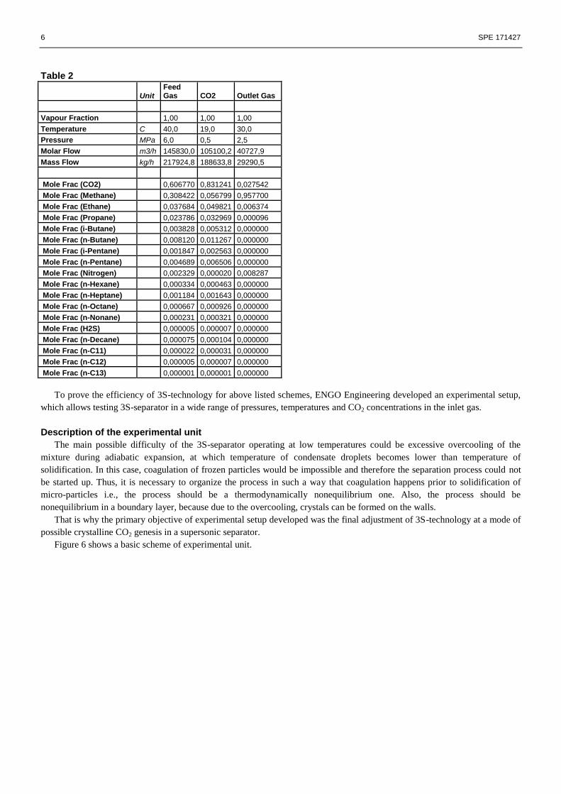
power plant. Table 2 presents data for more complex 3S-separation unit than shown in Fig. 4. In this case, CO2 concentration
in the outlet gas is 2%.
Table 1
Unit Inlet gas Outlet CO2
Outlet Gas
Vapour Fraction 1,00 1,00 1,00
Temperature C 45,0 -10,0 -9,6
Pressure MPag 6,7 0,1 2,5
Molar Flow m3/h_(gas) 11776,6 8351,6 3425,1
Mass Flow kg/h 18053,9 15153,2 2900,8
Mole Frac (Nitrogen) 0,004000 0,000011 0,013727
Mole Frac (CO2) 0,712018 0,949584 0,132736
Mole Frac (Methane) 0,268007 0,030888 0,846199
Mole Frac (Ethane) 0,011000 0,012814 0,006577
Mole Frac (H2S) 0,004975 0,006703 0,000761
6 SPE 171427
Table 2
Unit Feed Gas CO2 Outlet Gas
Vapour Fraction 1,00 1,00 1,00
Temperature C 40,0 19,0 30,0
Pressure MPa 6,0 0,5 2,5
Molar Flow m3/h 145830,0 105100,2 40727,9
Mass Flow kg/h 217924,8 188633,8 29290,5
Mole Frac (CO2) 0,606770 0,831241 0,027542
Mole Frac (Methane) 0,308422 0,056799 0,957700
Mole Frac (Ethane) 0,037684 0,049821 0,006374
Mole Frac (Propane) 0,023786 0,032969 0,000096
Mole Frac (i-Butane) 0,003828 0,005312 0,000000
Mole Frac (n-Butane) 0,008120 0,011267 0,000000
Mole Frac (i-Pentane) 0,001847 0,002563 0,000000
Mole Frac (n-Pentane) 0,004689 0,006506 0,000000
Mole Frac (Nitrogen) 0,002329 0,000020 0,008287
Mole Frac (n-Hexane) 0,000334 0,000463 0,000000
Mole Frac (n-Heptane) 0,001184 0,001643 0,000000
Mole Frac (n-Octane) 0,000667 0,000926 0,000000
Mole Frac (n-Nonane) 0,000231 0,000321 0,000000
Mole Frac (H2S) 0,000005 0,000007 0,000000
Mole Frac (n-Decane) 0,000075 0,000104 0,000000
Mole Frac (n-C11) 0,000022 0,000031 0,000000
Mole Frac (n-C12) 0,000005 0,000007 0,000000
Mole Frac (n-C13) 0,000001 0,000001 0,000000
To prove the efficiency of 3S-technology for above listed schemes, ENGO Engineering developed an experimental setup,
which allows testing 3S-separator in a wide range of pressures, temperatures and CO2 concentrations in the inlet gas.
Description of the experimental unit
The main possible difficulty of the 3S-separator operating at low temperatures could be excessive overcooling of the
mixture during adiabatic expansion, at which temperature of condensate droplets becomes lower than temperature of
solidification. In this case, coagulation of frozen particles would be impossible and therefore the separation process could not
be started up. Thus, it is necessary to organize the process in such a way that coagulation happens prior to solidification of
micro-particles i.e., the process should be a thermodynamically nonequilibrium one. Also, the process should be
nonequilibrium in a boundary layer, because due to the overcooling, crystals can be formed on the walls.
That is why the primary objective of experimental setup developed was the final adjustment of 3S-technology at a mode of
possible crystalline CO2 genesis in a supersonic separator.
Figure 6 shows a basic scheme of experimental unit.

SPE 171427 7
Fig.6 Scheme of experimental unit
The test setup consists of the following systems:
- investigated 3S-separator (see Fig. 7 showing a picture of the unit)
Fig.7 3S-separator, mounted at the experimental unit
- The methane injection system 1 consists of a high pressure methane source, control valve and a flow nozzle 7.
- Heat exchanger 2, where the preliminary cooldown of methane flow occurs, caused by the liquid nitrogen evaporation;
- The feed system 3, supplying liquid nitrogen into the heat exchanger (liquid nitrogen supply system 3), consists of a vessel
with liquid nitrogen and a pressure-feed system.
- The liquid CO2 supply system 4, used for mixing liquid CO2 with methane, includes CO2 storage vessel and nitrogen
pressure-feed system. The Carbon dioxide supply line is equipped with check valve 5, CO2 turbine flowmeter 6 and a flow
nozzle 7; after which the carbon dioxide is delivered into the methane line by means of the disperser 8. A check valve
prevents methane from entering into the carbon dioxide line;
- Two phase flow separation system (for the flow from 3S-separator) comprises cyclone separator 9;
- Gas sampling system 10. Samples are taken at three points of the test setup - from the feed mixture at the inlet of 3S-

8 SPE 171427
separator, at the outlet of 3S-separator and in the gas line at the outlet of cyclone separator 9. For each test point there is a
metal container and two remotely operated valves to take samples during each test run;
- A methane flare system 11 is installed at the outlet of the test setup. The flare system also prevents accumulation of
methane and its uncontrolled ignition;
- Instrumentation and controls system is installed at different points of test setup to obtain the required operation conditions
of test run and to analyze performance of the test setup. It consists out of a number of thermocouples, pressure gauges and
above-stated flow nozzles and turbine flowmeters. The sensor signals are measured and recorded by National Instruments
device and a РС.
The sequence of test setup experiments is the following. During the preparation for the experiment the required amount of
liquid nitrogen and liquid CO2 is supplied from permanent storage tanks to the supply system vessels. These supply vessels are
designed for supercharger pressure. The desired pressure values in these vessels can be set at closed components supply line.
Each test run begins with methane supply and setting of its required pressure at the inlet of 3S-separator, while at the same
time it is required to control the methane flame presence at the flare at the outlet of test setup. Then the liquid nitrogen line is
opened to the heat exchanger. Carbon dioxide supply valve will be opened, when the temperature of methane at the inlet of
separator falls down to a required level. And after the stabilization of its injection conditions, gas sampling is done. Then the
supply of CO2 and methane are closed and the methane line is blown down using gas nitrogen. Samples are taken and sent to
the portable containers for further analysis by a gas chromatograph.
Test results of 3S-separator with mixtures of Methane and CO2
Tests of 3S-separator were carried out at ENGO Engineering Laboratory in Moscow. The purpose of the tests was to
investigate conditions at which it is possible to purify CH4+CO2 mixture to concentrations less than 3% mol. For that purpose,
inlet mixture was cooled down to (-60) - (-70)°C.
The same equipment as in the previous series of experiments was used during the laboratory tests, but the gas-dynamic
channel was specially designed. Separation of two-phase boundary layer was implemented at a rate of 18-20% from total gas
mass flow rate through 3S-separator.
Some test results are shown in Fig. 8.
Fig.8 Dependence of 3S-separators operating efficiency
𝑎𝑜𝑢𝑡𝑙𝑒𝑡- concentration of CO2 (mol.) at the 3S outlet,
αinlet- - concentration of CO2 (mol.) at the 3S inlet,
T – gas temperature at the 3S inlet
0,00
0,10
0,20
0,30
0,40
0,50
0,60
0,70
0,80
0,90
-75 -70 -65 -60 -55 -50 -45 -40
T, оС

SPE 171427 9
As it follows from presented data, the main factor, which determines high rate of mixture purifying, is the temperature of
the inlet mixture.
During experiments, it has been shown, that in order to achieve a high rate of acid gas removal the inlet temperature should
be below -60°C. Only at these conditions it is possible to purify natural gas to CO2 concentration less than 4% mol.
Also the following factor helps to achieve high rate of mixture purifying: due to the centrifugal effect, mixture pressure in
the core of the flow is 25-30% less than at the periphery, which leads to additional adiabatic cooling of mixture flow.
The course of tests demonstrated the effectiveness of 3S-technology for CO2 separation and also proved the fact that
crystallization processes have no time to develop in the nozzle of supersonic separator. A coagulation and separation
processes, taking place in the nozzle, are accompanied by supercooled droplets, which are not crystallized yet.
Conclusions
Available technology of supersonic separation can be used for carbon dioxide removal from natural gases. 3S-technology
is most effective for natural gas with high CO2 content stripping, especially when it is difficult to use conventional
technologies.
Proposed schemes of 3S-separation units can provide CO2 concentration in the outlet of the unit less than 3 % mol. (at any
CO2 content in the inlet gas).
Tests of 3S-separators, conducted on hydrocarbon mixtures, containing CO2, have shown that the developed 3S-separator
provides the desired efficiency of CO2 separation from natural gases.
References
[1] Mehdi Panahi, Cryogenic CO2/H2S capture technologies for
remote natural gas processing, Trial Lecture, 2011
[2] http://www.fischer-tropsch.org/DOE/DOE_reports/GRI/gri-86_0009-1/86_0009-1, Part 4, Pages 298 - 409.pdf
[3] E. Keskes, C.S. Adjiman, A. Galindo, and G. Jackson, a physical absorption process for the capture of CO2 from CO2-rich natural
gas streams, Chemical Engineering Department, Imperial College London, http://www.geos.ed.ac.uk/ccs/Publications/Keskes.pdf
[4] J. Hao, P.A. Rice, S.A. Stern, Upgrading low-quality natural gas with H2S and CO2 selective polymer membranes: Part I. Process
design and economics of membrane stages without recycle streams, Journal of Membrane Science, 209, 1, 177-206
[5] A. S. Holmes, J. M. Ryan, Cryogenic distillation separation of acid gases from methane, US patent, 1982
[6] J. A. Valencia, B. K. Mentzer, Processing of High CO2and H2S Gas with Controlled Freeze Zone™ Technology, ExxonMobil
Upstream Research Company GASEX 2008 Conference
[7] J. A. Valencia, P. S. Northorp, C. J. Mart, Controlled Freeze Zone™ Technology for enabling processing of high CO2 and H2S gas
reserves, ExxonMobil Upstream Research Company IPTC 12708 (2008)
[8] B.T.Kelly, J. A. Valencia, P. S. Northorp, C. J. Mart, Controlled Freeze Zone™ for developing sour gas reserves, Energy Procedia 4
(2011), 824-829
[9] C. Condon, M. Parker, Shute Creek Gas Treating Facility Project Updates, The Wyoming Enhanced Oil Recovery Institute 5th
Annual Wyoming CO2 Capture Conference, 13 July 2011
[10] Bruce W. Klint, Peter R. Dale, Charles Stephenson Low Quality Natural Gas Sulfur Removal and Recovery CNG Claus Sulfur
Recovery Process // Pilot Plant Test Program/ DOE Contract DE-AC21-92MC29470
[11] A. Hart and N. Gnanendran, Cryogenic CO2 Capture in Natural Gas, Energy Procedia 1 (2009), 697-706
[12] http://www.total.com/MEDIAS/MEDIAS_INFOS/239/EN/sour-gas-2007.pdf
[13] F. Lallemand, F. Lecomte and C. Striecher, “Highly Sour Gas Processing, H2S bulk removal with the Sprex Process”, IPTC 10581,
2005
[14] Korytnikov R.V., Yakhontov D.A., Bagirov L.A., Dmitriev L.M., Imaev S.Z. Industrial tests of supersonic separation technology at
low temperature separation unit of UPMT of "1-S" gas complex treatment unit of Zapolyarny oil and gas fields’ complex// Petroleum
engineering Journal, №6, 2012
[15] Andreev O.P., Minigulov R.M., Korytnikov R.V., Bagirov L.A., Imaev S.Z. Technological schemes of GPP based on 3S-technology
for the northern oil-gas condensate fields //Science and Technology of Gas Industry Journal, №2, 2009
[16] Vadim Alfyorov, Lev Bagirov, Leonard Dmitriev, Vladimir Feygin, Salavat Imayev, John R. Lacey. Supersonic nozzle efficiently
separates natural gas components // Oil & Gas Journal, May 23, 2005
Related Documents