SPE 149548 New well foundation concept, as used at a Norwegian Sea well Trond Sivertsen, SPE, Det norske oljeselskap ASA; and Harald Strand, SPE, NeoDrill AS Copyright 2011, Society of Petroleum Engineers This paper was prepared for presentation at the SPE Arctic and Extreme Environments Conference & Exhibition held in Moscow, Russia, 18–20 October 2011. This paper was selected for presentation by an SPE program committee following review of information contained in an abstract submitted by the author(s). Contents of the paper have not been reviewed by the Society of Petroleum Engineers and are subject to correction by the author(s). The material does not necessarily reflect any position of the Society of Petroleum Engineers, its officers, or members. Electronic reproduction, distribution, or storage of any part of this paper without the written consent of the Society of Petroleum Engineers is prohibited. Permission to reproduce in print is restricted to an abstract of not more than 300 words; illustrations may not be copied. The abstract must contain conspicuous acknowledgment of SPE copyright. Abstract. A new and safer, high load capacity well construction concept has been developed. This new well foundation system as installed at a Norwegian Sea well location by Det norske oljeselskap ASA, is described herein, as well as its use and recovery. Heavy Blow Out Preventers (BOP) are normally used on drilling rigs designed for deep water and arctic applications, and heavier BOPs will have a negative impact on the stability of the well head. To mitigate these negative impacts, a new suction anchor type well foundation concept; CAN (Conductor Anchor Node) has been developed. The CAN unit provides sufficient load capacity for safely carrying heavy BOPs as well as X-Mas trees, thus protecting the well from fatigue capacity “consumption” in the drilling phase. The use of the concept will also reduce cuttings and cement disposal to the sea, which may be further important aspects in arctic and sensitive marine environment areas. The CAN will also mitigate the risks of the well becoming over-loaded by undesired, accidental loads, e.g.: as a result of a rig drive off/drift off situation. This is achieved by mobilising substantial carrying capacity from the soil through the CAN’s large cross sectional area and captured soil mass. This is an important aspect in view of risk mitigation and improving possibilities of applying contingency means in case of undesired events or disasters, such as the Macondo case. The concept offers significant advantages in reducing rig time; as it enables pre-rig conductor installation, thus reducing top-hole construction costs and rig failure risk exposure. The concept’s viability and advantages have been demonstrated by a number of full scale applications ranging from 270 m to 1 150m water depth on the Norwegian Continental Shelf. The CAN will be a facilitator for safe jetting of conductors (only short length conductor needed), as well as being an enabler for achieving successful cement jobs (if installed by drilling and cementing), as the conductor remains supported and motionless during cement set-up. Introduction. As drilling rigs day rates increase, there is a growing need of reducing the required rig time to drill the wells. For drilling the top-hole section (30” & 20” casings) of the wells, no pressure control and fluids return to the drilling unit is needed, or possible. Hence, this part of the well operations lends itself to use of alternative, smaller well construction units, to save rig time through pre-rig well construction. For this purpose a more efficient, vessel friendly conductor installation method is needed.

Welcome message from author
This document is posted to help you gain knowledge. Please leave a comment to let me know what you think about it! Share it to your friends and learn new things together.
Transcript

SPE 149548
New well foundation concept, as used at a Norwegian Sea well Trond Sivertsen, SPE, Det norske oljeselskap ASA; and Harald Strand, SPE, NeoDrill AS
Copyright 2011, Society of Petroleum Engineers This paper was prepared for presentation at the SPE Arctic and Extreme Environments Conference & Exhibition held in Moscow, Russia, 18–20 October 2011. This paper was selected for presentation by an SPE program committee following review of information contained in an abstract submitted by the author(s). Contents of the paper have not been reviewed by the Society of Petroleum Engineers and are subject to correction by the author(s). The material does not necessarily reflect any position of the Society of Petroleum Engineers, its officers, or members. Electronic reproduction, distribution, or storage of any part of this paper without the written consent of the Society of Petroleum Engineers is prohibited. Permission to reproduce in print is restricted to an abstract of not more than 300 words; illustrations may not be copied. The abstract must contain conspicuous acknowledgment of SPE copyright.
Abstract.
A new and safer, high load capacity well construction concept has been developed. This new well foundation
system as installed at a Norwegian Sea well location by Det norske oljeselskap ASA, is described herein, as well as
its use and recovery. Heavy Blow Out Preventers (BOP) are normally used on drilling rigs designed for deep water
and arctic applications, and heavier BOPs will have a negative impact on the stability of the well head. To
mitigate these negative impacts, a new suction anchor type well foundation concept; CAN (Conductor Anchor
Node) has been developed. The CAN unit provides sufficient load capacity for safely carrying heavy BOPs as well
as X-Mas trees, thus protecting the well from fatigue capacity “consumption” in the drilling phase. The use of the
concept will also reduce cuttings and cement disposal to the sea, which may be further important aspects in
arctic and sensitive marine environment areas.
The CAN will also mitigate the risks of the well becoming over-loaded by undesired, accidental loads, e.g.: as a
result of a rig drive off/drift off situation. This is achieved by mobilising substantial carrying capacity from the soil
through the CAN’s large cross sectional area and captured soil mass. This is an important aspect in view of risk
mitigation and improving possibilities of applying contingency means in case of undesired events or disasters,
such as the Macondo case.
The concept offers significant advantages in reducing rig time; as it enables pre-rig conductor installation, thus
reducing top-hole construction costs and rig failure risk exposure. The concept’s viability and advantages have
been demonstrated by a number of full scale applications ranging from 270 m to 1 150m water depth on the
Norwegian Continental Shelf.
The CAN will be a facilitator for safe jetting of conductors (only short length conductor needed), as well as being
an enabler for achieving successful cement jobs (if installed by drilling and cementing), as the conductor remains
supported and motionless during cement set-up.
Introduction.
As drilling rigs day rates increase, there is a growing need of reducing the required rig time to drill the wells. For
drilling the top-hole section (30” & 20” casings) of the wells, no pressure control and fluids return to the drilling
unit is needed, or possible. Hence, this part of the well operations lends itself to use of alternative, smaller well
construction units, to save rig time through pre-rig well construction. For this purpose a more efficient, vessel
friendly conductor installation method is needed.

2 SPE 149548
Also, field cases have clearly demonstrated that the present well design does not carry any contingency load
capacity for accidental loads. Such loads may e.g.: be caused by rig drive off or drift off situations, which in most
cases will lead to well head /conductor failures, and in turn loss of the entire well.
To facilitate efficient pre-rig well construction and prevent accidental load caused well damages, a new design
philosophy has been developed, based on the use of a suction anchor type of well foundation named CAN
(Conductor Anchor Node). The CAN structure will guide the conductor during its installation, as well as giving it
mechanical support after installation, such that the conductor is turned into a very high lateral load capacity and
bending stiff construction. In this way, the “system weak link” is transferred from below to above the BOP.
Hence, accidental peak loads will have to be “consumed” by the Marine Riser and the Flex joint, which in extreme
cases may also suffer damage. However, these parts are all accessible and replaceable, leaving an undamaged
BOP and well.
Technology description.
The CAN is a specially designed suction
anchor type of structure. It consists basically
of an open ended (down) cylindrical outer
shell with a strong lid section and a
concentric centre pipe / conductor guide,
which extends as deep as the CAN skirt. This
construction allows installation without water
leakage through the CAN centre, as the
conductor guide will penetrate as deep as the
CAN skirt into the soil, and thus a closed in
volume is attained without the use of a
centre pipe lid.
A typical CAN weight will be 60-80 tons, with
following outline dimensions: D = 5-6 m, H =
8-12m, giving a soil penetration capacity of
up to 10-11m.
The CAN is pre-installed by a fit for purpose
DP-vessel, fitted with a heave compensated
crane, suitable for the job. At location, the
vessel crane picks up and runs the CAN to
near sea bed, where it is switched to Active
Heave Compensated (AHC) mode to set down
and attain a controlled CAN self-penetration.
There after the ROV equipped with a suitable
pump is docked to the CAN to pump out the
captured water, thus reducing the CAN internal pressure. The pressure differential attained in this way will in turn
generate a net downwards directed force, which will push the CAN further into the sediments. Through the large
lid area, substantial push-in forces can be mobilised by applying moderate differential pressures, e.g.: on a D = 6m
CAN, having a nearly 30m2 lid area, a ΔP of 2 bar will generate a CAN push-in force of nearly 600 ton!
Fig. 1. CAN / Conductor typical stack-up

SPE 149548 3
To optimise the CAN design, specific location soil information is utilised to optimise the CAN’s D and H
dimensions to achieve needed well load capacity. Through the CAN’s large contact area to the soil, the entire BOP
and casing loads may be carried by the CAN.
Once the CAN is in place, the same installation vessel may be used to undertake the conductor installation. As the
CAN is designed to be the main load carrying member, the conductor may now be shortened to say 3 joints (30-
35m). The conductor is pre-assembled onshore into one joint (by welding), such that by a simple crane operation,
the conductor is lifted horizontally off the deck and into the water, where it is up-righted to a vertical position
before it is run and stabbed into the CAN conductor guide to self-penetrate. Thereafter, a hydraulic hammer is
run to drive the conductor into the soil until landing its WHH in the CAN. In this way the conductor is ”installed by
wire”, which is a much more cost efficient method than drilling and cementing. Fig. 1. illustrates a typical CAN /
Conductor stack-up.
If so preferred for various reasons, the conductor may also be installed through the CAN by the Drilling Unit, by
jetting. It is to be noted that the CAN will facilitate safe and predictable conductor jetting, as shorter conductor
strings will be needed. Hence, the inherent risks of high conductor stick up have been mitigated by use of the
CAN, as well as risks of insufficient load capacity. By using the CAN, conductor jetting becomes a predictable,
robust and possibly the most cost efficient conductor installation alternative available.
Substantial advantages may also be attained by using a pre-installed CAN, through which the conductor is drilled
for, installed and subsequently cemented by the rig, as shown in Fig. 2. below:
Fig. 2. Conventional and CAN conductor cementation comparison
4 SPE 149548
To be especially noted from above is that the CAN will facilitate superior conductor load capacity, in using shorter
conductor and less cement. Improved cement curing conditions are also provided by:
Motionless conductor, being “captured” by the CAN’s conductor guide pipe.
Low temperature curing conditions at sea bed avoided (no need for return to sea bed)
The CAN based well design offers a number of technical advantages, e.g.:
High axial load capacity – suitable for the heaviest BOPs
High lateral load capacity:
o Increased bending stiffness and reduced fatigue “consumption” in the well drilling phase.
o Significantly increased accidental load capacity – well loss risk mitigation.
Pre-rig well construction enabled:
o Reduced rig time & accelerated production
o Reduced top-hole construction costs
Reduced cuttings and cement disposal (if drilling and cementing)
Enables safe conductor installation by jetting
Reduced environmental foot print (less CO2 emission, NOX, etc.)
Enables Pre-rig well construction
Operational experience
CAN Installation
CAN units have been installed on a number of NCS well
locations, ranging from 270m to 1150m water depth
and it has been combined with rig jetted conductors,
rig drilled and cemented conductor as well as driven,
vessel installed conductor. For the subject Norwegian
Sea well, which was to be drilled at a very soft sea bed
location, the main objective of the CAN installation
was to ensure that a high load capacity conductor was
attained. This was needed to prepare for the 6th Gen
rig Aker Barents’ heavy BOP, weighing nearly 400 ton.
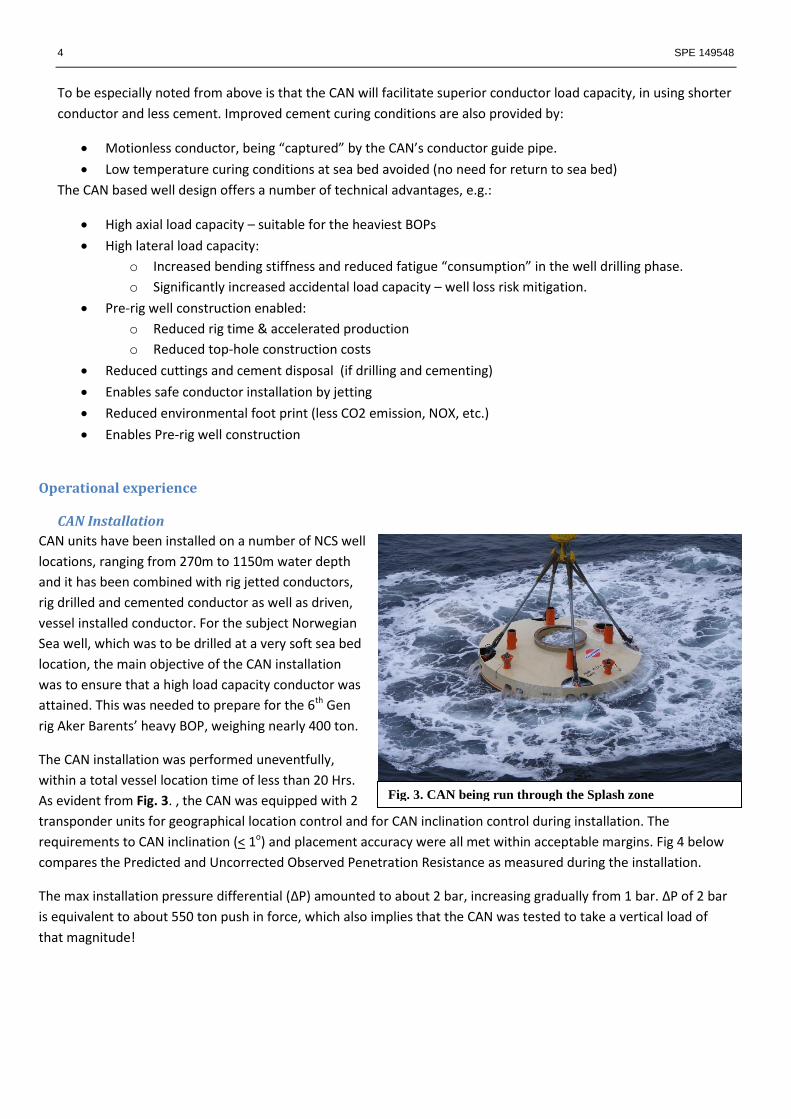
The CAN installation was performed uneventfully,
within a total vessel location time of less than 20 Hrs.
As evident from Fig. 3. , the CAN was equipped with 2
transponder units for geographical location control and for CAN inclination control during installation. The
requirements to CAN inclination (< 1o) and placement accuracy were all met within acceptable margins. Fig 4 below
compares the Predicted and Uncorrected Observed Penetration Resistance as measured during the installation.
The max installation pressure differential (ΔP) amounted to about 2 bar, increasing gradually from 1 bar. ΔP of 2 bar
is equivalent to about 550 ton push in force, which also implies that the CAN was tested to take a vertical load of
that magnitude!
Fig. 3. CAN being run through the Splash zone

SPE 149548 5
A near full CAN penetration (10.5m vs. 11m) was also achieved. The explanation of this difference is most likely that
the soil displaced by the CAN steel skirt penetration was moved to the CAN inside, due to the pressure differential.
This volume corresponds to a “mud heave”
inside the CAN of about 0.5 m.
The installation experience from this well
show that an installation weather window
of < 3.5 m HS would apply for the selected
vessel. This window is needed for about 4
hours, to ensure bringing the CAN safely off
deck and through the splash zone. Once the
CAN is through the splash zone, heavier
weather conditions may be accepted.
All ROV operations were successfully
performed, proving the capability of the
Vessel / ROV / Crane cooperation. The rig
arrived location after the CAN was in place,
where after the conductor was drilled for,
installed and cemented uneventfully. In
spite of the soft sea bed formation, full
cement returns could be taken to sea bed
through the CAN, thus cementing the
conductor into the CAN conductor guide.
This experience shows that for conductor /
CAN cement jobs, the excess cement
volume can be reduced from 200 to 0%. This will dramatically reduce the total cement volume, mixing and pumping
time. The post well CAN recovery showed that an excellent cement quality had been attained to top of CAN, which
most likely can be attributed to optimum cementing conditions: No pipe movements or cement stirring during
cement setting.
CAN recovery
Following the well drilling operations as per plan, the well was plugged
by the rig prior to leaving the 20” & 30” conductor cutting and CAN
recovery operations to be performed by a fit for purpose vessel.
The cutting operations were performed as per plan; i.e.: cutting the 20”
+ 30” in one cutting sweep below the conductor guide pipe. Thereafter
the CAN recovery operations were commenced by reversing the
installation process: The ROV now pumping water into the CAN. After
pumping the CAN out about 60% of its total embedded length, the
remaining CAN length had to be pumped / lifted out of the soil. After
being freed from the sea bed, the CAN including the cut 30” + 20” was
lifted to surface, as shown in Fig. 5. before it was lifted on board the
vessel by the vessel AHC crane.
Fig. 4. Predicted and Uncorrected Observed Penetration Resistance
Fig. 5. CAN recovered to surface

6 SPE 149548
Bumper bars had been installed on board the vessel to catch the
CAN when swinging it in over the deck, and set it on the planked
deck down in a controlled manner, as shown in Fig. 6.
Noticeable was the about 10 cm thick clay layer on the CAN
outside. This demonstrates the presence of high steel/soil friction,
as the shear by pull out had taken place out in the soil and not
along the CAN steel periphery.
After chaining the CAN /conductor unit down and sea fastening it
to the deck, it was transported to shore by the vessel. The CAN was
placed in a horizontal position on the dock side, where the 30”
conductor / 20” strings and Well Head assemblies were separated
from the CAN. Thereafter the CAN was cleaned and readied for the
next well foundation operation. This operation demonstrated that
the CAN is a versatile, rugged unit, which may be reused for a
number of well installations.
HSE performance
The vessel operations were all well prepared with risk assessment and HIRA (Hazard Identification and Risk
Assessment) sessions. The CAN installation operations were performed without any HSE related incidents, and
have demonstrated that the CAN operations may be performed safely and with very few manual operations.
Previous operations have also demonstrated the conductor may be run “hands free”, which is a significant
advantage compared to handling large diameter pipe on the drill floor of conventional rigs. Hence, it may be
concluded that the CAN concept offers improved work conditions for the rig crew, by transferring the conductor
handling from the rig to a “hands-off” operation on the vessel.
Further, it is concluded that conductor installation by vessels (as enabled by the CAN) will reduce the
“environmental foot print” for conductor installation through use of smaller vessels with reduced CO2 and NOX
emission, as well as reduced cuttings and cement disposal.
Conclusions
The CAN concept opens new possibilities for safer and more cost efficient well construction. By means of the
CAN, higher load capacity wells (conductors) can be installed than attainable with conventional technology.
Ample accidental load capacity is provided by the CAN’s superior bending stiffness, such that any accidental load
impacts will be directed above the BOP.
Its application in arctic and cold climate will give several important advantages, such as reduced conductor
length, giving reduced cement volume, shorter cement jobs and reduced waiting on cement. Also an improved
cement quality environment is created through motionless conductor whilst cement setting and no requirement
to cement in the extreme low temperature environment at sea bed. The conductor installation will also have a
reduced environmental foot print compared to conventional rig installation.
Acknowledgement
Det norske Oljeselskap’s active participation in preparing and planning this demonstration project, which resulted
in technically high quality execution of the vessel operations, were highly appreciated by all parties involved.
Fig. 6. CAN landed on vessel deck
Related Documents