Volume 3—Power Distribution and Control Assemblies CA08100004E—April 2014 www.eaton.com V3-T2-1 2 2 2 2 2 2 2 2 2 2 2 2 2 2 2 2 2 2 2 2 2 2 2 2 2 2 2 2 2 2 SPD, Power Conditioning, PF Capacitors and Harmonic Filters Industrial Surge Protection Products 2.1 Surge Protection and Power Conditioning Introduction . . . . . . . . . . . . . . . . . . . . . . . . . . . . . . . . . . . . . . . . . . . . . V3-T2-2 Product Overview . . . . . . . . . . . . . . . . . . . . . . . . . . . . . . . . . . . . . . . . . V3-T2-5 SPD Series for Integration into Electrical Distribution Equipment . . . . V3-T2-7 SPD Series for Mounting External to Electrical Distribution Equipment V3-T2-11 SPV Surge Protective Device . . . . . . . . . . . . . . . . . . . . . . . . . . . . . . . . V3-T2-16 CVX050/100 . . . . . . . . . . . . . . . . . . . . . . . . . . . . . . . . . . . . . . . . . . . . . V3-T2-18 SP1 Surge Protective Device . . . . . . . . . . . . . . . . . . . . . . . . . . . . . . . . V3-T2-21 SP2 Surge Protective Device . . . . . . . . . . . . . . . . . . . . . . . . . . . . . . . . V3-T2-23 AEGIS Powerline Filters . . . . . . . . . . . . . . . . . . . . . . . . . . . . . . . . . . . . V3-T2-25 Sag Ride-Through (SRT) . . . . . . . . . . . . . . . . . . . . . . . . . . . . . . . . . . . . V3-T2-30 Electronic Voltage Regulator (EVR) . . . . . . . . . . . . . . . . . . . . . . . . . . . . V3-T2-36 2.2 Power Factor Correction and Harmonic Filtering Product Overview . . . . . . . . . . . . . . . . . . . . . . . . . . . . . . . . . . . . . . . . V3-T2-38 UNIPUMP . . . . . . . . . . . . . . . . . . . . . . . . . . . . . . . . . . . . . . . . . . . . . . V3-T2-41 UNIPAK . . . . . . . . . . . . . . . . . . . . . . . . . . . . . . . . . . . . . . . . . . . . . . . . . V3-T2-44 AUTOVAR 300 Automatic Power Factor Correction Capacitor Systems V3-T2-55 AUTOVAR 600 Automatic Power Factor Correction Capacitor Systems V3-T2-58 AUTOVAR Filter—LV Automatic Harmonic Filter . . . . . . . . . . . . . . . . . . V3-T2-63 Transient-Free Static Switching Power Factor Correction Units . . . . . . V3-T2-67 Active-Harmonic Filter-Harmonic Correction Unit—NEMA 1 Enclosure V3-T2-71

Welcome message from author
This document is posted to help you gain knowledge. Please leave a comment to let me know what you think about it! Share it to your friends and learn new things together.
Transcript
Volume 3—Power Distribution and Control Assemblies CA08100004E—April 2014 www.eaton.com V3-T2-1
2
2
2
2
2
2
2
2
2
2
2
2
2
2
2
2
2
2
2
2
2
2
2
2
2
2
2
2
2
2
SPD, Power Conditioning, PF Capacitorsand Harmonic Filters
Industrial Surge Protection Products 2.1 Surge Protection and Power Conditioning
Introduction . . . . . . . . . . . . . . . . . . . . . . . . . . . . . . . . . . . . . . . . . . . . . V3-T2-2
Product Overview . . . . . . . . . . . . . . . . . . . . . . . . . . . . . . . . . . . . . . . . . V3-T2-5
SPD Series for Integration into Electrical Distribution Equipment . . . . V3-T2-7
SPD Series for Mounting External to Electrical Distribution Equipment V3-T2-11
SPV Surge Protective Device . . . . . . . . . . . . . . . . . . . . . . . . . . . . . . . . V3-T2-16
CVX050/100 . . . . . . . . . . . . . . . . . . . . . . . . . . . . . . . . . . . . . . . . . . . . . V3-T2-18
SP1 Surge Protective Device . . . . . . . . . . . . . . . . . . . . . . . . . . . . . . . . V3-T2-21
SP2 Surge Protective Device . . . . . . . . . . . . . . . . . . . . . . . . . . . . . . . . V3-T2-23
AEGIS Powerline Filters . . . . . . . . . . . . . . . . . . . . . . . . . . . . . . . . . . . . V3-T2-25
Sag Ride-Through (SRT) . . . . . . . . . . . . . . . . . . . . . . . . . . . . . . . . . . . . V3-T2-30
Electronic Voltage Regulator (EVR) . . . . . . . . . . . . . . . . . . . . . . . . . . . . V3-T2-36
2.2 Power Factor Correction and Harmonic Filtering
Product Overview . . . . . . . . . . . . . . . . . . . . . . . . . . . . . . . . . . . . . . . . V3-T2-38
UNIPUMP . . . . . . . . . . . . . . . . . . . . . . . . . . . . . . . . . . . . . . . . . . . . . . V3-T2-41
UNIPAK. . . . . . . . . . . . . . . . . . . . . . . . . . . . . . . . . . . . . . . . . . . . . . . . . V3-T2-44
AUTOVAR 300 Automatic Power Factor Correction Capacitor Systems V3-T2-55
AUTOVAR 600 Automatic Power Factor Correction Capacitor Systems V3-T2-58
AUTOVAR Filter—LV Automatic Harmonic Filter. . . . . . . . . . . . . . . . . . V3-T2-63
Transient-Free Static Switching Power Factor Correction Units . . . . . . V3-T2-67
Active-Harmonic Filter-Harmonic Correction Unit—NEMA 1 Enclosure V3-T2-71
V3-T2-2 Volume 3—Power Distribution and Control Assemblies CA08100004E—April 2014 www.eaton.com
2
2
2
2
2
2
2
2
2
2
2
2
2
2
2
2
2
2
2
2
2
2
2
2
2
2
2
2
2
2
2.1 SPD, Power Conditioning, PF Capacitors and Harmonic Filters
Surge Protection and Power Conditioning
Industrial and Commercial Surge Protection ContentsDescription Page
IntroductionProduct Overview . . . . . . . . . . . . . . . . . . . . . . . . . . . V3-T2-5
SPD Series for Integration into Electrical Distribution Equipment . . . . . . . . . . . . . . . . . . . . . V3-T2-7
SPD Series for Mounting External to Electrical Distribution Equipment. . . . . . . . . . . . . . V3-T2-11
SPV Surge Protective Device . . . . . . . . . . . . . . . . . . V3-T2-16CVX050/100 . . . . . . . . . . . . . . . . . . . . . . . . . . . . . . . V3-T2-18SP1 Surge Protective Device . . . . . . . . . . . . . . . . . . V3-T2-21
SP2 Surge Protective Device . . . . . . . . . . . . . . . . . . V3-T2-23AEGIS Powerline Filters . . . . . . . . . . . . . . . . . . . . . . V3-T2-25Sag Ride-Through (SRT) . . . . . . . . . . . . . . . . . . . . . . V3-T2-30
Electronic Voltage Regulator (EVR) . . . . . . . . . . . . . . V3-T2-36
IntroductionIndustrial and Commercial Surge Protection● SPD Series for Integration
into Electrical Distribution Equipment
● SPD Series for Mounting External to Electrical Distribution Equipment
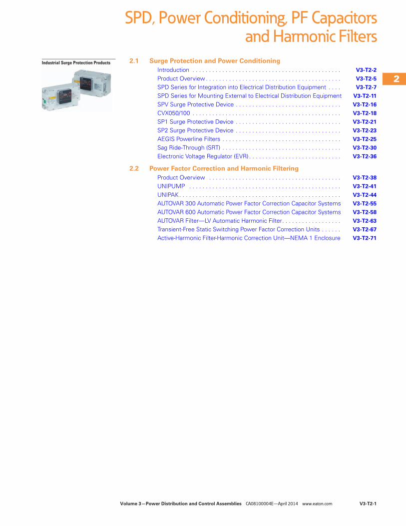
SPD Series Integrated UnitsSpecification grade surge protective devices installed within Eaton’s electrical assemblies.
SPD Series Integrated Unit
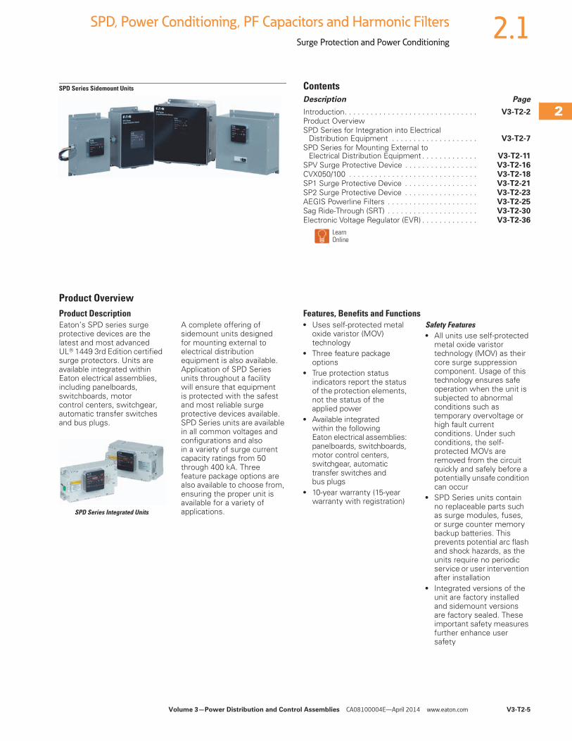
SPD Series Sidemount UnitsSpecification grade surge protective devices for installation external to electrical distribution equipment.
SPD Series Sidemount Unit
Critical Load ProtectionSeries filtering and surge protection for critical single-phase loads.
● Current ratings up to 60A● 120 and 240 Vac units● 24 and 48 Vdc units● DIN mounting available on
some models● Up to 80 kA of peak surge
protection● Most AC units are UL 1449
3rd Edition and UL 1283 5th Edition listed
AEGIS Products
Commercial and Light Industrial Surge ProtectionEaton’s SPV series is a commercial grade and light industrial surge protective device (SPD) that combines surge suppression components and EMI/RFI filtering, providing effective protection for sensitive electronic loads.
Surges (also known as transients), due to lightning, utility grid switching, switching of external/internal inductive or capacitive loads, and other sources, travel on power line conductors throughout the electrical distribution system, causing system operating problems and equipment downtime.
SPV Series
Volume 3—Power Distribution and Control Assemblies CA08100004E—April 2014 www.eaton.com V3-T2-3
2
2
2
2
2
2
2
2
2
2
2
2
2
2
2
2
2
2
2
2
2
2
2
2
2
2
2
2
2
2
2.1SPD, Power Conditioning, PF Capacitors and Harmonic Filters
Surge Protection and Power Conditioning
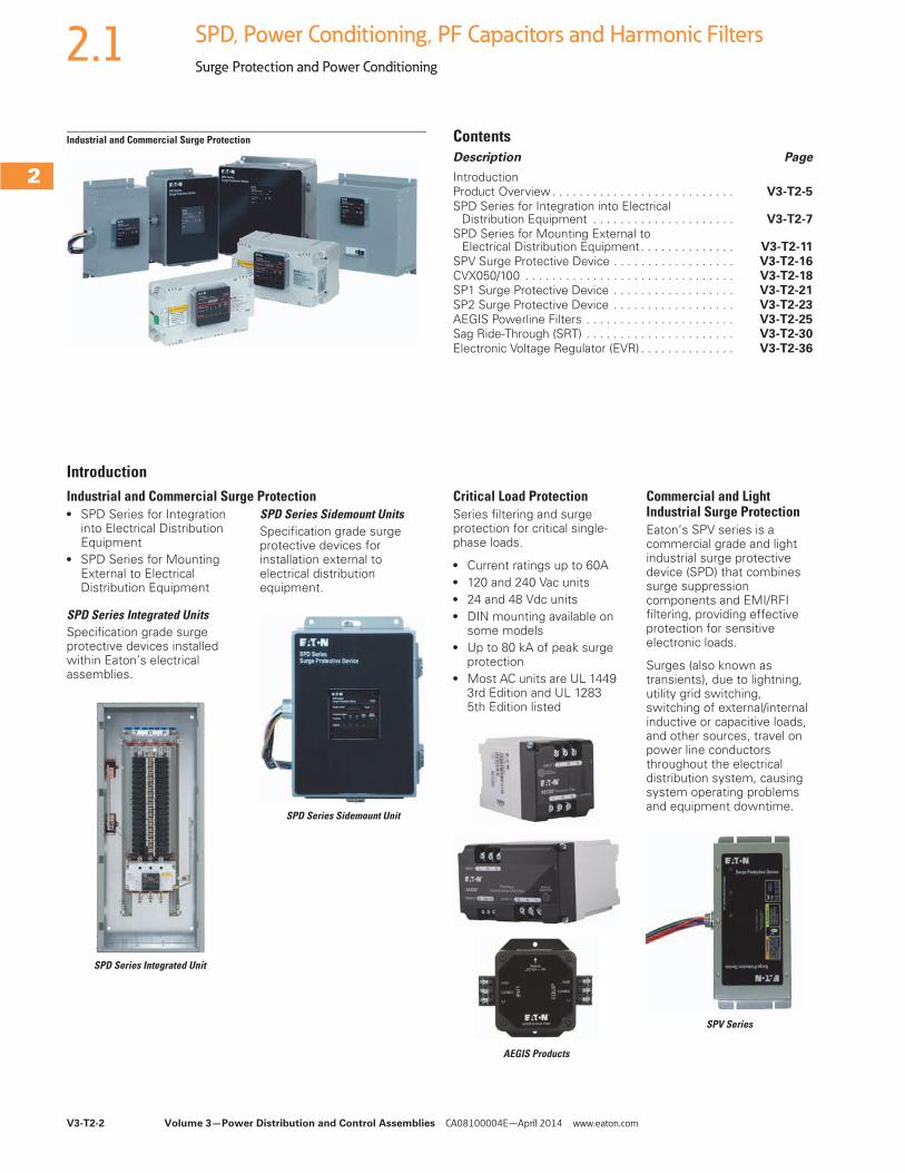
Surge Protection for Sub-Panel and OEM ApplicationsIn today’s business environment that calls for 24 hours a day, 7 days a week uptime and reliability, Eaton’s CVX050 and CVX100 surge protective devices (SPDs) ensure that a customer’s investment in equipment and processes is protected from the damaging effects of voltage transients. Designed for installation on service entrance, branch panels or individual equipment disconnects, the CVX050/100 provides enhanced surge protection for mission-critical applications.
Panelboards with Integrated Surge Protective Devices● Available in standard and
custom configurations● Ratings:
● 120/240 Vac, single-phase, three-wire
● 208Y/120 Vac, three-phase, four-wire
● 480Y/277 Vac, three-phase, four-wire
● 600Y/347 Vac, three-phase, four-wire (other voltage configurations are available)
● Copper bus● 12, 18, 24, 30, 36 and
42 circuits● Bolt-on branch breakers● A full range of factory
installed modifications and accessories
● Fully rated or series rated
Surge Protective Devices can be Integrated within a variety of Eaton
Electrical Assemblies
Power Conditioning
Sag Ride-Through (SRT)The sag ride-through (SRT) is a power conditioner that corrects voltage sags to maintain uptime and productivity.
Electronic Voltage Regulator (EVR)The electronic voltage regulator (EVR) is designed to meet the needs of customers who experience voltage regulation problems due to brownout conditions from their electric utilities.
Electronic Voltage Regulator (EVR)Sag Ride-Through (SRT)
Facility-Wide Power Protection Solutions
A facility-wide protection approach should be employed to address power quality issues. This approach minimizes overall lifecycle costs and optimizes facility uptime. The following is a recommended design approach for implementing facility-wide Eaton power protection solutions.
The most accepted design methodology is based on two concepts:
1. Ensure proper grounding conditions exist. All forms of power protection/conditioning rely on good grounding, bonding and earthing practices.
2. Surge protection should be installed at key distribution panels and critical loads.
V3-T2-4 Volume 3—Power Distribution and Control Assemblies CA08100004E—April 2014 www.eaton.com
2
2
2
2
2
2
2
2
2
2
2
2
2
2
2
2
2
2
2
2
2
2
2
2
2
2
2
2
2
2
2.1 SPD, Power Conditioning, PF Capacitors and Harmonic Filters
Surge Protection and Power Conditioning
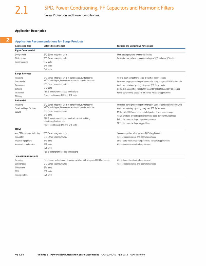
Application Description
Application Recommendations for Surge Products
Application Type Eaton’s Surge Product Features and Competitive Advantages
Light Commercial
Design build
Chain stores
Small facilities
SPD Series integrated units
SPD Series sidemount units
SPV units
SP1 units
CVX units
Ideal package for any commercial facility
Cost-effective, reliable protection using the SPD Series or SPV units
Large Projects
Including:
Commercial
Government
Schools
Institution
Military
SPD Series integrated units in panelboards, switchboards, MCCs, switchgear, busway and automatic transfer switches
SPD Series sidemount units
SPV units
AEGIS units for critical load applications
Power conditioners (EVR and SRT units)
Able to meet competitors’ surge protection specifications
Increased surge protection performance by using integrated SPD Series units
Wall space savings by using integrated SPD Series units
Quick-ship capabilities from Eaton assembly satellites and service centers
Power conditioning capability for a wide variety of applications
Industrial
Including:
Small and large facilities
WWTP
SPD Series integrated units in panelboards, switchboards, MCCs, switchgear, busway and automatic transfer switches
SPD Series sidemount units
SPV units
AEGIS units for critical load applications such as PLCs, robotics applications, etc.
Power conditioners (EVR and SRT units)
Increased surge protection performance by using integrated SPD Series units
Wall space savings by using integrated SPD Series units
MCCs with SPD Series units installed protect drives from damage
AEGIS products protect expensive critical loads from harmful damage
EVR units correct voltage regulation problems
SRT units correct voltage sag problems
OEM
Any OEM customer including:
Integrators
Medical equipment
Automation and control
SPD Series integrated units
SPD Series sidemount units
SPV units
SP1 units
CVX units
AEGIS units for critical load applications
Years of experience in a variety of OEM applications
Application assistance and recommendations
Small footprint enables integration in a variety of applications
Ability to meet customized requirements
Telecommunications
Including:
Cellular sites
Microwave
PCS
Paging systems
Panelboards and automatic transfer switches with integrated SPD Series units
SPD Series sidemount units
SPV units
SP1 units
CVX units
Ability to meet customized requirements
Application assistance and recommendations
Volume 3—Power Distribution and Control Assemblies CA08100004E—April 2014 www.eaton.com V3-T2-5
2
2
2
2
2
2
2
2
2
2
2
2
2
2
2
2
2
2
2
2
2
2
2
2
2
2
2
2
2
2
2.1SPD, Power Conditioning, PF Capacitors and Harmonic Filters
Surge Protection and Power Conditioning
SPD Series Sidemount Units ContentsDescription Page
Introduction. . . . . . . . . . . . . . . . . . . . . . . . . . . . . . . V3-T2-2Product OverviewSPD Series for Integration into Electrical
Distribution Equipment . . . . . . . . . . . . . . . . . . . . V3-T2-7
SPD Series for Mounting External to Electrical Distribution Equipment . . . . . . . . . . . . . V3-T2-11
SPV Surge Protective Device . . . . . . . . . . . . . . . . . V3-T2-16CVX050/100 . . . . . . . . . . . . . . . . . . . . . . . . . . . . . . V3-T2-18SP1 Surge Protective Device . . . . . . . . . . . . . . . . . V3-T2-21
SP2 Surge Protective Device . . . . . . . . . . . . . . . . . V3-T2-23AEGIS Powerline Filters . . . . . . . . . . . . . . . . . . . . . V3-T2-25Sag Ride-Through (SRT) . . . . . . . . . . . . . . . . . . . . . V3-T2-30
Electronic Voltage Regulator (EVR) . . . . . . . . . . . . . V3-T2-36
LearnOnline
Product OverviewProduct DescriptionEaton’s SPD series surge protective devices are the latest and most advanced UL® 1449 3rd Edition certified surge protectors. Units are available integrated within Eaton electrical assemblies, including panelboards, switchboards, motor control centers, switchgear, automatic transfer switches and bus plugs.
SPD Series Integrated Units
A complete offering of sidemount units designed for mounting external to electrical distribution equipment is also available. Application of SPD Series units throughout a facility will ensure that equipment is protected with the safest and most reliable surge protective devices available. SPD Series units are available in all common voltages and configurations and also in a variety of surge current capacity ratings from 50 through 400 kA. Three feature package options are also available to choose from, ensuring the proper unit is available for a variety of applications.
Features, Benefits and Functions● Uses self-protected metal
oxide varistor (MOV) technology
● Three feature package options
● True protection status indicators report the status of the protection elements, not the status of the applied power
● Available integrated within the following Eaton electrical assemblies: panelboards, switchboards, motor control centers, switchgear, automatic transfer switches andbus plugs
● 10-year warranty (15-year warranty with registration)
Safety Features● All units use self-protected
metal oxide varistor technology (MOV) as their core surge suppression component. Usage of this technology ensures safe operation when the unit is subjected to abnormal conditions such as temporary overvoltage or high fault current conditions. Under such conditions, the self-protected MOVs are removed from the circuit quickly and safely before a potentially unsafe condition can occur
● SPD Series units contain no replaceable parts such as surge modules, fuses, or surge counter memory backup batteries. This prevents potential arc flash and shock hazards, as the units require no periodic service or user intervention after installation
● Integrated versions of the unit are factory installed and sidemount versions are factory sealed. These important safety measures further enhance user safety
V3-T2-6 Volume 3—Power Distribution and Control Assemblies CA08100004E—April 2014 www.eaton.com
2
2
2
2
2
2
2
2
2
2
2
2
2
2
2
2
2
2
2
2
2
2
2
2
2
2
2
2
2
2
2.1 SPD, Power Conditioning, PF Capacitors and Harmonic Filters
Surge Protection and Power Conditioning
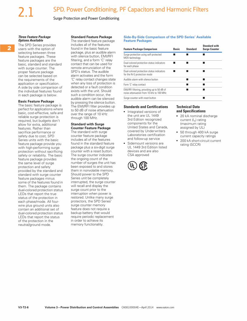
Three Feature Package Options AvailableThe SPD Series provides users with the option of selecting between three feature packages. These feature packages are the basic, standard and standard with surge counter. The proper feature package can be selected based on the requirements of the application or specification.A side by side comparison of the individual features found in each package is below.
Basic Feature PackageThe basic feature package is perfect for applications where basic, cost-effective, safe and reliable surge protection is required, but budgets don’t allow for extra, additional features. Rather than sacrifice performance or safety due to cost, SPD Series units with the basic feature package provide you with high-performing surge protection without sacrificing safety or reliability. The basic feature package provides the same level of surge protection and safety provided by the standard and standard with surge counter feature packages minus some of the features found in them. The package contains dual-colored protection status LEDs that report the true status of the protection in each phase/mode. All four-wire plus ground units also contain an additional set of dual-colored protection status LEDs that report the status of the protection in the neutral/ground mode.
Standard Feature PackageThe standard feature package includes all of the features found in the basic feature package, plus an audible alarm with silence button, EMI/RFI filtering, and a form ‘C’ relay contact that can be used for remote annunciation of the SPD’s status. The audible alarm activates and the form ‘C’ relay contact changes state when any loss of protection is detected or a fault condition exists with the unit. Should such a condition occur, the audible alarm can be silenced by pressing the silence button. The EMI/RFI filter provides up to 50 dB of noise attenuation over the range of 10 kHz through 100 MHz.
Standard with Surge Counter Feature PackageThe standard with surge counter feature package includes all of the features found in the standard feature package plus a six-digit surge counter with a reset button. The surge counter indicates the ongoing count of the number of surges the unit has been exposed to and stores them in nonvolatile memory. Should power to the SPD Series unit be completely interrupted, the surge counter will recall and display the surge count prior to the interruption when power is restored. Unlike many surge protectors, the SPD Series’ surge counter memory feature does not require a backup battery that would require periodic replacement in order to achieve its memory functionality.
Side-By-Side Comparison of the SPD Series’ Available Feature Packages
Standards and Certifications● Integrated versions of
the unit are UL 1449 3rd Edition recognized components for the United States and Canada, covered by Underwriters Laboratories certification and follow-up service
● Sidemount versions are UL 1449 3rd Edition listed devices and are also CSA approved
Technical Data and Specifications● 20 kA nominal discharge
current (In) rating (maximum rating assigned by UL)
● 50 through 400 kA surge current capacity ratings
● 200 kA short-circuit current rating (SCCR)
Feature Package Comparison Basic StandardStandard with Surge Counter
Surge protection using self-protected MOV technology
■ ■ ■
Dual-colored protection status indicators for each phase
■ ■ ■
Dual-colored protection status indicators for the N-G protection mode
■ ■ ■
Audible alarm with silence button ■ ■
Form ‘C’ relay contact ■ ■
EMI/RFI filtering, providing up to 50 dB of noise attenuation from 10 kHz to 100 MHz
■ ■
Surge counter with reset button ■
Volume 3—Power Distribution and Control Assemblies CA08100004E—April 2014 www.eaton.com V3-T2-7
2
2
2
2
2
2
2
2
2
2
2
2
2
2
2
2
2
2
2
2
2
2
2
2
2
2
2
2
2
2
2.1SPD, Power Conditioning, PF Capacitors and Harmonic Filters
Surge Protection and Power Conditioning
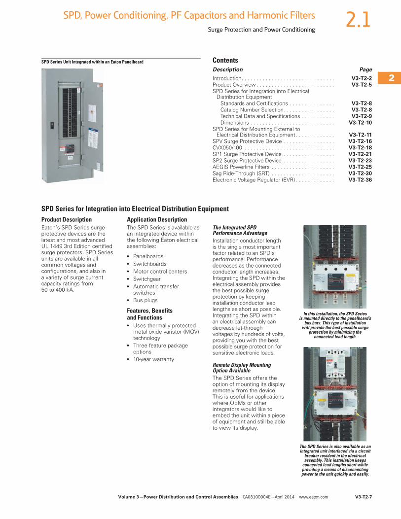
SPD Series Unit Integrated within an Eaton Panelboard ContentsDescription Page
Introduction. . . . . . . . . . . . . . . . . . . . . . . . . . . . . . . V3-T2-2Product Overview . . . . . . . . . . . . . . . . . . . . . . . . . . V3-T2-5
SPD Series for Integration into Electrical Distribution Equipment
Standards and Certifications . . . . . . . . . . . . . . . V3-T2-8Catalog Number Selection. . . . . . . . . . . . . . . . . V3-T2-8Technical Data and Specifications . . . . . . . . . . . V3-T2-9
Dimensions . . . . . . . . . . . . . . . . . . . . . . . . . . . . V3-T2-10SPD Series for Mounting External to
Electrical Distribution Equipment . . . . . . . . . . . . . V3-T2-11SPV Surge Protective Device . . . . . . . . . . . . . . . . . V3-T2-16CVX050/100 . . . . . . . . . . . . . . . . . . . . . . . . . . . . . . V3-T2-18
SP1 Surge Protective Device . . . . . . . . . . . . . . . . . V3-T2-21SP2 Surge Protective Device . . . . . . . . . . . . . . . . . V3-T2-23AEGIS Powerline Filters . . . . . . . . . . . . . . . . . . . . . V3-T2-25
Sag Ride-Through (SRT) . . . . . . . . . . . . . . . . . . . . . V3-T2-30Electronic Voltage Regulator (EVR) . . . . . . . . . . . . . V3-T2-36
SPD Series for Integration into Electrical Distribution EquipmentProduct DescriptionEaton’s SPD Series surge protective devices are the latest and most advanced UL 1449 3rd Edition certified surge protectors. SPD Series units are available in all common voltages and configurations, and also in a variety of surge current capacity ratings from 50 to 400 kA.
Application DescriptionThe SPD Series is available as an integrated device within the following Eaton electrical assemblies:
● Panelboards● Switchboards● Motor control centers● Switchgear● Automatic transfer
switches● Bus plugs
Features, Benefits and Functions● Uses thermally protected
metal oxide varistor (MOV) technology
● Three feature package options
● 10-year warranty
The Integrated SPD Performance AdvantageInstallation conductor length is the single most important factor related to an SPD’s performance. Performance decreases as the connected conductor length increases. Integrating the SPD within the electrical assembly provides the best possible surge protection by keeping installation conductor lead lengths as short as possible. Integrating the SPD within an electrical assembly can decrease let-through voltages by hundreds of volts, providing you with the best possible surge protection for sensitive electronic loads.
Remote Display Mounting Option AvailableThe SPD Series offers the option of mounting its display remotely from the device. This is useful for applications where OEMs or other integrators would like to embed the unit within a piece of equipment and still be able to view its display.
In this installation, the SPD Series is mounted directly to the panelboard’s
bus bars. This type of installation will provide the best possible surge
protection by minimizing the connected lead length.
The SPD Series is also available as an integrated unit interfaced via a circuit
breaker resident in the electrical assembly. This installation keeps
connected lead lengths short while providing a means of disconnecting power to the unit quickly and easily.
V3-T2-8 Volume 3—Power Distribution and Control Assemblies CA08100004E—April 2014 www.eaton.com
2
2
2
2
2
2
2
2
2
2
2
2
2
2
2
2
2
2
2
2
2
2
2
2
2
2
2
2
2
2
2.1 SPD, Power Conditioning, PF Capacitors and Harmonic Filters
Surge Protection and Power Conditioning
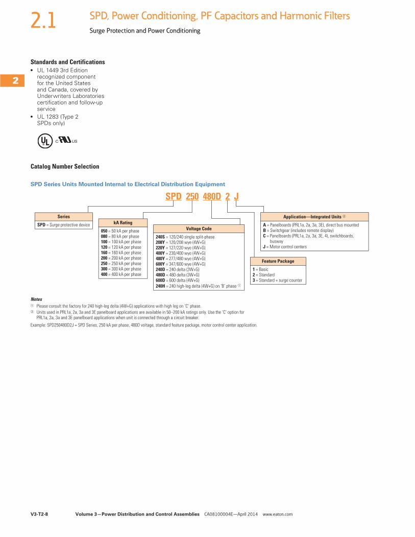
Standards and Certifications ● UL 1449 3rd Edition
recognized component for the United States and Canada, covered by Underwriters Laboratories certification and follow-up service
● UL 1283 (Type 2 SPDs only)
Catalog Number Selection
SPD Series Units Mounted Internal to Electrical Distribution Equipment
Notes1 Please consult the factory for 240 high-leg delta (4W+G) applications with high leg on ‘C’ phase.2 Units used in PRL1a, 2a, 3a and 3E panelboard applications are available in 50–200 kA ratings only. Use the ‘C’ option for
PRL1a, 2a, 3a and 3E panelboard applications when unit is connected through a circuit breaker.
Example: SPD250480D2J = SPD Series, 250 kA per phase, 480D voltage, standard feature package, motor control center application.
Series
SPD = Surge protective device kA Rating
050 = 50 kA per phase080 = 80 kA per phase100 = 100 kA per phase120 = 120 kA per phase160 = 160 kA per phase200 = 200 kA per phase250 = 250 kA per phase300 = 300 kA per phase400 = 400 kA per phase
Voltage Code
240S = 120/240 single split-phase208Y = 120/208 wye (4W+G)220Y = 127/220 wye (4W+G)400Y = 230/400 wye (4W+G)480Y = 277/480 wye (4W+G)600Y = 347/600 wye (4W+G)240D = 240 delta (3W+G)480D = 480 delta (3W+G)600D = 600 delta (4W+G)240H = 240 high-leg delta (4W+G) on ‘B’ phase 1
Application—Integrated Units 2
A = Panelboards (PRL1a, 2a, 3a, 3E), direct bus mountedB = Switchgear (includes remote display)C = Panelboards (PRL1a, 2a, 3a, 3E, 4), switchboards,
buswayJ = Motor control centers
Feature Package
1 = Basic 2 = Standard 3 = Standard + surge counter
SPD 250 480D 2 J
Volume 3—Power Distribution and Control Assemblies CA08100004E—April 2014 www.eaton.com V3-T2-9
2
2
2
2
2
2
2
2
2
2
2
2
2
2
2
2
2
2
2
2
2
2
2
2
2
2
2
2
2
2
2.1SPD, Power Conditioning, PF Capacitors and Harmonic Filters
Surge Protection and Power Conditioning
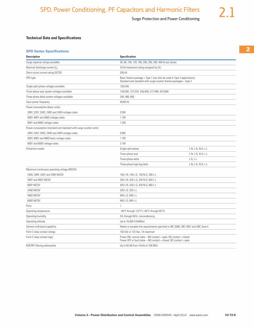
Technical Data and Specifications
SPD Series Specifications
Description Specification
Surge capacity ratings available 50, 80, 100, 120, 160, 200, 250, 300, 400 kA per phase
Nominal discharge current (In) 20 kA (maximum rating assigned by UL)
Short-circuit current rating (SCCR) 200 kA
SPD type Basic feature package = Type 1 (can also be used in Type 2 applications)Standard and standard with surge counter feature packages = Type 2
Single split-phase voltages available 120/240
Three-phase wye system voltages available 120/208, 127/220, 230/400, 277/480, 347/600
Three-phase delta system voltages available 240, 480, 600
Input power frequency 50/60 Hz
Power consumption (basic units):
208Y, 220Y, 240S, 240D and 240H voltage codes 0.5W
400Y, 480Y and 480D voltage codes 1.1W
600Y and 600D voltage codes 1.3W
Power consumption (standard and standard with surge counter units):
208Y, 220Y, 240S, 240D and 240H voltage codes 0.6W
400Y, 480Y and 480D basic voltage codes 1.7W
600Y and 600D voltage codes 2.1W
Protection modes Single split-phase L-N, L-G, N-G, L-L
Three-phase wye L-N, L-G, N-G, L-L
Three-phase delta L-G, L-L
Three-phase high-leg delta L-N, L-G, N-G, L-L
Maximum continuous operating voltage (MCOV):
240S, 208Y, 220Y and 240H MCOV 150 L-N, 150 L-G, 150 N-G, 300 L-L
400Y and 480Y MCOV 320 L-N, 320 L-G, 320 N-G, 640 L-L
600Y MCOV 420 L-N, 420 L-G, 420 N-G, 840 L-L
240D MCOV 320 L-G, 320 L-L
480D MCOV 640 L-G, 640 L-L
600D MCOV 840 L-G, 840 L-L
Ports 1
Operating temperature –40°F through 122°F (–40°C through 50°C)
Operating humidity 5% through 95%, noncondensing
Operating altitude Up to 16,000 ft (5000m)
Seismic withstand capability Meets or exceeds the requirements specified in IBC 2006, CBC 2007 and UBC Zone 4
Form C relay contact ratings 150 Vdc or 125 Vac, 1A maximum
Form C relay contact logic Power ON, normal state—NO contact = open, NC contact = closedPower OFF or fault state—NO contact = closed, NC contact = open
EMI/RFI filtering attenuation Up to 50 dB from 10 kHz to 100 MHz
V3-T2-10 Volume 3—Power Distribution and Control Assemblies CA08100004E—April 2014 www.eaton.com
2
2
2
2
2
2
2
2
2
2
2
2
2
2
2
2
2
2
2
2
2
2
2
2
2
2
2
2
2
2
2.1 SPD, Power Conditioning, PF Capacitors and Harmonic Filters
Surge Protection and Power Conditioning
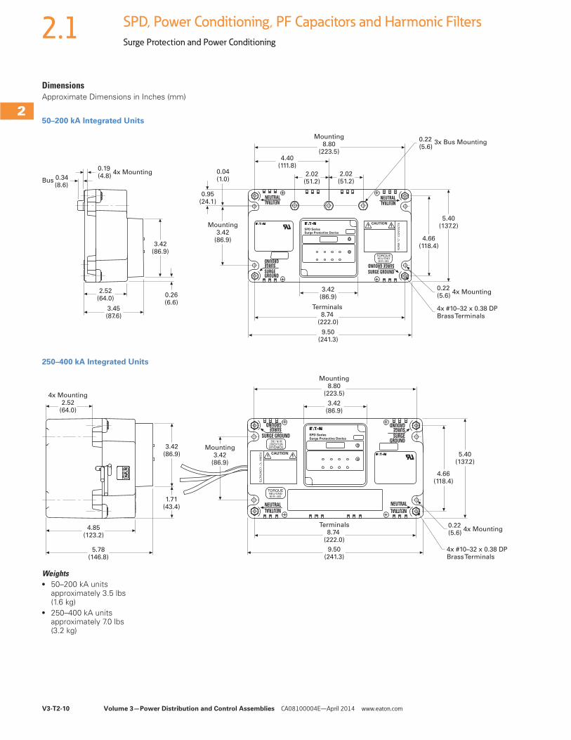
DimensionsApproximate Dimensions in Inches (mm)
50–200 kA Integrated Units
250–400 kA Integrated Units
Weights● 50–200 kA units
approximately 3.5 lbs (1.6 kg)
● 250–400 kA units approximately 7.0 lbs (3.2 kg)
0.19(4.8)
4x Mounting
Bus 0.34(8.6)
3.42(86.9)
2.52(64.0)
3.45(87.6)
0.95(24.1)
Mounting8.80
(223.5)4.40
(111.8)0.04(1.0)
5.40(137.2)
4.66(118.4)
0.22(5.6)
4x Mounting
4x #10–32 x 0.38 DPBrass Terminals
3.42(86.9)
Terminals 8.74
(222.0)
9.50(241.3)
0.26(6.6)
0.22(5.6)
3x Bus Mounting
Mounting3.42
(86.9)
2.02(51.2)
2.02(51.2)
FO
RM
“C
” C
ON
TA
CT
SCAUTION
SURGE GROUND
NEUTRAL
SURGE GROUND
NEUTRALNEUTRALNEUTRAL
TORQUENEU/GND36 IN. LBS.
SURGEGROUND
SURGEGROUND
SPD SeriesSurge Protective Device
5.78(146.8)
4.85(123.2)
1.71(43.4)
3.42(86.9)
4x Mounting2.52
(64.0)
9.50(241.3)
Terminals8.74
(222.0)
Mounting8.80
(223.5)
3.42(86.9)
5.40(137.2)
4.66(118.4)
0.22(5.6)
4x Mounting
4x #10–32 x 0.38 DPBrass Terminals
Mounting3.42
(86.9)
FO
RM
“C
” C
ON
TA
CT
S
CAUTION
SURGE GROUND
NEUTRAL
SURGEGROUND
NEUTRAL NEUTRALNEUTRAL
TORQUENEU/GND36 IN. LBS.
TORQUENEU/GND36 IN. LBS.
SURGEGROUND
SURGEGROUND
SPD SeriesSurge Protective Device
Volume 3—Power Distribution and Control Assemblies CA08100004E—April 2014 www.eaton.com V3-T2-11
2
2
2
2
2
2
2
2
2
2
2
2
2
2
2
2
2
2
2
2
2
2
2
2
2
2
2
2
2
2
2.1SPD, Power Conditioning, PF Capacitors and Harmonic Filters
Surge Protection and Power Conditioning
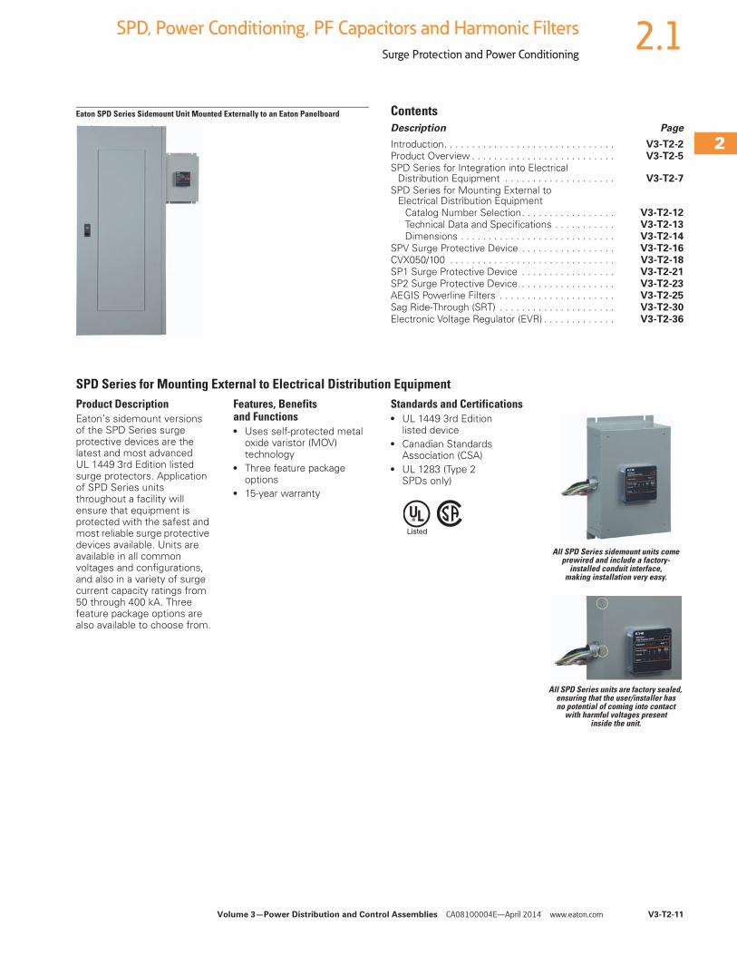
Eaton SPD Series Sidemount Unit Mounted Externally to an Eaton Panelboard ContentsDescription Page
Introduction. . . . . . . . . . . . . . . . . . . . . . . . . . . . . . . V3-T2-2Product Overview . . . . . . . . . . . . . . . . . . . . . . . . . . V3-T2-5
SPD Series for Integration into Electrical Distribution Equipment . . . . . . . . . . . . . . . . . . . . V3-T2-7
SPD Series for Mounting External to Electrical Distribution Equipment
Catalog Number Selection. . . . . . . . . . . . . . . . . V3-T2-12Technical Data and Specifications . . . . . . . . . . . V3-T2-13Dimensions . . . . . . . . . . . . . . . . . . . . . . . . . . . . V3-T2-14
SPV Surge Protective Device . . . . . . . . . . . . . . . . . V3-T2-16CVX050/100 . . . . . . . . . . . . . . . . . . . . . . . . . . . . . . V3-T2-18SP1 Surge Protective Device . . . . . . . . . . . . . . . . . V3-T2-21
SP2 Surge Protective Device . . . . . . . . . . . . . . . . . V3-T2-23AEGIS Powerline Filters . . . . . . . . . . . . . . . . . . . . . V3-T2-25Sag Ride-Through (SRT) . . . . . . . . . . . . . . . . . . . . . V3-T2-30
Electronic Voltage Regulator (EVR) . . . . . . . . . . . . . V3-T2-36
SPD Series for Mounting External to Electrical Distribution EquipmentProduct DescriptionEaton’s sidemount versions of the SPD Series surge protective devices are the latest and most advanced UL 1449 3rd Edition listed surge protectors. Application of SPD Series units throughout a facility will ensure that equipment is protected with the safest and most reliable surge protective devices available. Units are available in all common voltages and configurations, and also in a variety of surge current capacity ratings from 50 through 400 kA. Three feature package options are also available to choose from.
Features, Benefits and Functions● Uses self-protected metal
oxide varistor (MOV) technology
● Three feature package options
● 15-year warranty
Standards and Certifications ● UL 1449 3rd Edition
listed device● Canadian Standards
Association (CSA)● UL 1283 (Type 2
SPDs only)
All SPD Series sidemount units come prewired and include a factory-
installed conduit interface, making installation very easy.
All SPD Series units are factory sealed, ensuring that the user/installer has no potential of coming into contact
with harmful voltages present inside the unit.
V3-T2-12 Volume 3—Power Distribution and Control Assemblies CA08100004E—April 2014 www.eaton.com
2
2
2
2
2
2
2
2
2
2
2
2
2
2
2
2
2
2
2
2
2
2
2
2
2
2
2
2
2
2
2.1 SPD, Power Conditioning, PF Capacitors and Harmonic Filters
Surge Protection and Power Conditioning
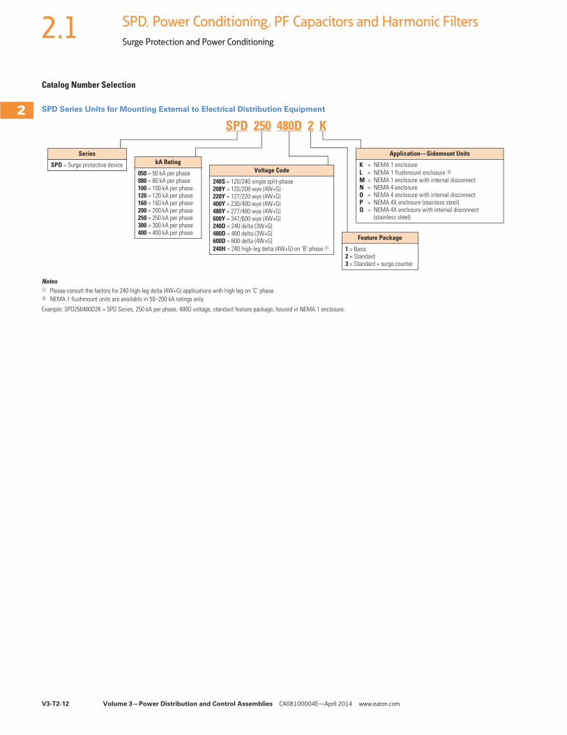
Catalog Number Selection
SPD Series Units for Mounting External to Electrical Distribution Equipment
Notes1 Please consult the factory for 240 high-leg delta (4W+G) applications with high leg on ‘C’ phase.2 NEMA 1 flushmount units are available in 50–200 kA ratings only.
Example: SPD250480D2K = SPD Series, 250 kA per phase, 480D voltage, standard feature package, housed in NEMA 1 enclosure.
Series
SPD = Surge protective device kA Rating
050 = 50 kA per phase080 = 80 kA per phase100 = 100 kA per phase120 = 120 kA per phase160 = 160 kA per phase200 = 200 kA per phase250 = 250 kA per phase300 = 300 kA per phase400 = 400 kA per phase
Voltage Code
240S = 120/240 single split-phase208Y = 120/208 wye (4W+G)220Y = 127/220 wye (4W+G)400Y = 230/400 wye (4W+G)480Y = 277/480 wye (4W+G)600Y = 347/600 wye (4W+G)240D = 240 delta (3W+G)480D = 480 delta (3W+G)600D = 600 delta (4W+G)240H = 240 high-leg delta (4W+G) on ‘B’ phase 1
Application—Sidemount Units
K = NEMA 1 enclosureL = NEMA 1 flushmount enclosure 2M = NEMA 1 enclosure with internal disconnectN = NEMA 4 enclosureO = NEMA 4 enclosure with internal disconnectP = NEMA 4X enclosure (stainless steel)Q = NEMA 4X enclosure with internal disconnect
(stainless steel)
Feature Package
1 = Basic 2 = Standard 3 = Standard + surge counter
SPD 250 480D 2 K
Volume 3—Power Distribution and Control Assemblies CA08100004E—April 2014 www.eaton.com V3-T2-13
2
2
2
2
2
2
2
2
2
2
2
2
2
2
2
2
2
2
2
2
2
2
2
2
2
2
2
2
2
2
2.1SPD, Power Conditioning, PF Capacitors and Harmonic Filters
Surge Protection and Power Conditioning
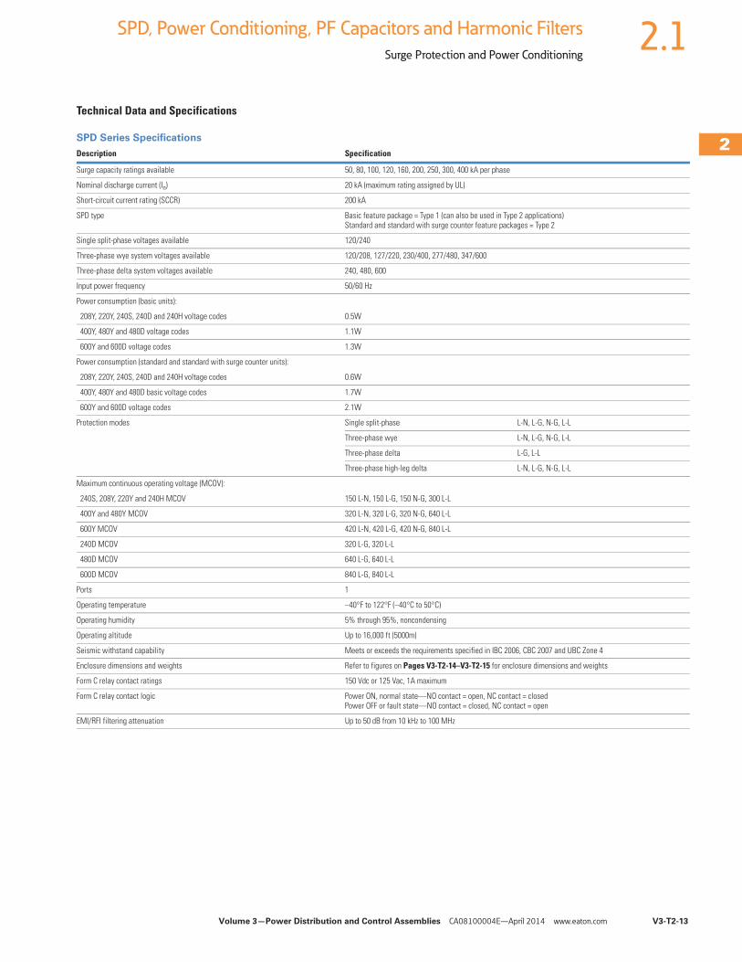
Technical Data and Specifications
SPD Series Specifications
Description Specification
Surge capacity ratings available 50, 80, 100, 120, 160, 200, 250, 300, 400 kA per phase
Nominal discharge current (In) 20 kA (maximum rating assigned by UL)
Short-circuit current rating (SCCR) 200 kA
SPD type Basic feature package = Type 1 (can also be used in Type 2 applications)Standard and standard with surge counter feature packages = Type 2
Single split-phase voltages available 120/240
Three-phase wye system voltages available 120/208, 127/220, 230/400, 277/480, 347/600
Three-phase delta system voltages available 240, 480, 600
Input power frequency 50/60 Hz
Power consumption (basic units):
208Y, 220Y, 240S, 240D and 240H voltage codes 0.5W
400Y, 480Y and 480D voltage codes 1.1W
600Y and 600D voltage codes 1.3W
Power consumption (standard and standard with surge counter units):
208Y, 220Y, 240S, 240D and 240H voltage codes 0.6W
400Y, 480Y and 480D basic voltage codes 1.7W
600Y and 600D voltage codes 2.1W
Protection modes Single split-phase L-N, L-G, N-G, L-L
Three-phase wye L-N, L-G, N-G, L-L
Three-phase delta L-G, L-L
Three-phase high-leg delta L-N, L-G, N-G, L-L
Maximum continuous operating voltage (MCOV):
240S, 208Y, 220Y and 240H MCOV 150 L-N, 150 L-G, 150 N-G, 300 L-L
400Y and 480Y MCOV 320 L-N, 320 L-G, 320 N-G, 640 L-L
600Y MCOV 420 L-N, 420 L-G, 420 N-G, 840 L-L
240D MCOV 320 L-G, 320 L-L
480D MCOV 640 L-G, 640 L-L
600D MCOV 840 L-G, 840 L-L
Ports 1
Operating temperature –40°F to 122°F (–40°C to 50°C)
Operating humidity 5% through 95%, noncondensing
Operating altitude Up to 16,000 ft (5000m)
Seismic withstand capability Meets or exceeds the requirements specified in IBC 2006, CBC 2007 and UBC Zone 4
Enclosure dimensions and weights Refer to figures on Pages V3-T2-14–V3-T2-15 for enclosure dimensions and weights
Form C relay contact ratings 150 Vdc or 125 Vac, 1A maximum
Form C relay contact logic Power ON, normal state—NO contact = open, NC contact = closedPower OFF or fault state—NO contact = closed, NC contact = open
EMI/RFI filtering attenuation Up to 50 dB from 10 kHz to 100 MHz
V3-T2-14 Volume 3—Power Distribution and Control Assemblies CA08100004E—April 2014 www.eaton.com
2
2
2
2
2
2
2
2
2
2
2
2
2
2
2
2
2
2
2
2
2
2
2
2
2
2
2
2
2
2
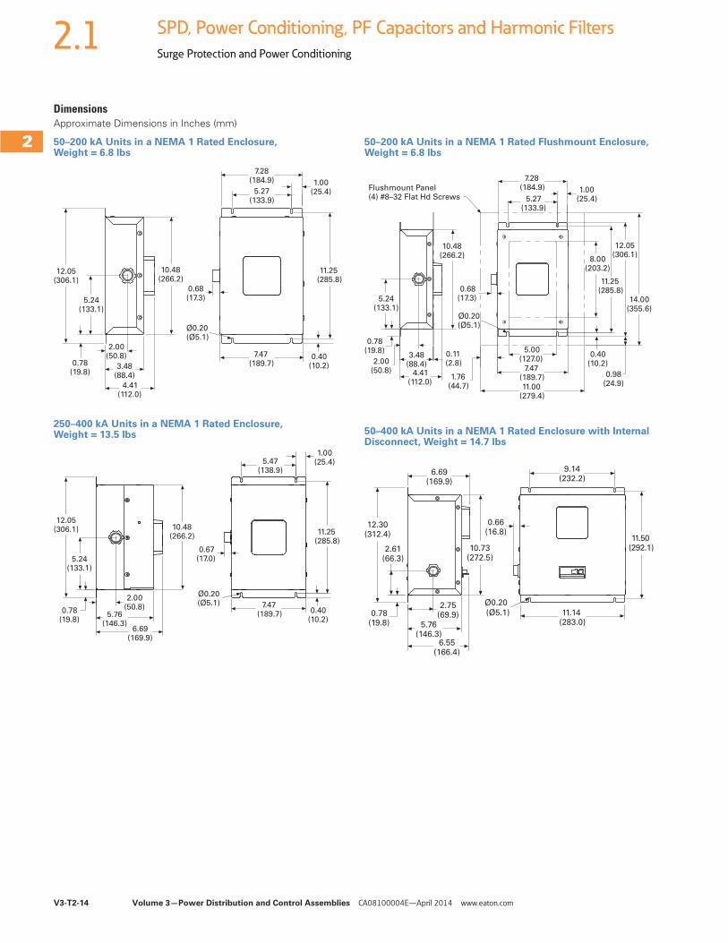
2.1 SPD, Power Conditioning, PF Capacitors and Harmonic Filters
Surge Protection and Power Conditioning
DimensionsApproximate Dimensions in Inches (mm)
50–200 kA Units in a NEMA 1 Rated Enclosure, Weight = 6.8 lbs
250–400 kA Units in a NEMA 1 Rated Enclosure, Weight = 13.5 lbs
12.05(306.1)
5.24(133.1)
0.78(19.8)
2.00(50.8)
3.48(88.4)
4.41(112.0)
Ø0.20(Ø5.1)
10.48(266.2)
0.68(17.3)
7.28(184.9)
5.27(133.9)
1.00(25.4)
11.25(285.8)
7.47(189.7)
0.40(10.2)
12.05(306.1)
5.24(133.1)
0.78(19.8)
2.00(50.8)
5.76(146.3)
6.69(169.9)
0.40(10.2)
7.47(189.7)
Ø0.20(Ø5.1)
10.48(266.2)
0.67(17.0)
5.47(138.9)
1.00(25.4)
11.25(285.8)
50–200 kA Units in a NEMA 1 Rated Flushmount Enclosure, Weight = 6.8 lbs
50–400 kA Units in a NEMA 1 Rated Enclosure with Internal Disconnect, Weight = 14.7 lbs
Flushmount Panel(4) #8–32 Flat Hd Screws
5.24(133.1)
0.78(19.8)
2.00(50.8)
3.48(88.4)
4.41(112.0)
0.11(2.8)
10.48(266.2)
0.68(17.3)
Ø0.20(Ø5.1)
1.76(44.7)
5.00(127.0)
7.47(189.7)
11.00(279.4)
0.40(10.2)
0.98(24.9)
8.00(203.2)
11.25(285.8)
12.05(306.1)
14.00(355.6)
1.00(25.4)
7.28(184.9)
5.27(133.9)
6.69(169.9)
12.30(312.4)
2.61(66.3)
0.78(19.8)
2.75(69.9)
5.76(146.3)
6.55(166.4)
10.73(272.5)
0.66(16.8)
Ø0.20
(Ø5.1) 11.14(283.0)
11.50(292.1)
9.14(232.2)
Volume 3—Power Distribution and Control Assemblies CA08100004E—April 2014 www.eaton.com V3-T2-15
2
2
2
2
2
2
2
2
2
2
2
2
2
2
2
2
2
2
2
2
2
2
2
2
2
2
2
2
2
2
2.1SPD, Power Conditioning, PF Capacitors and Harmonic Filters
Surge Protection and Power Conditioning
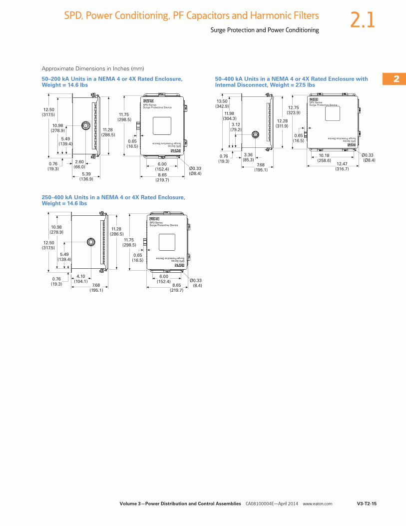
Approximate Dimensions in Inches (mm)
50–200 kA Units in a NEMA 4 or 4X Rated Enclosure, Weight = 14.6 lbs
250–400 kA Units in a NEMA 4 or 4X Rated Enclosure, Weight = 14.6 lbs
50–400 kA Units in a NEMA 4 or 4X Rated Enclosure with Internal Disconnect, Weight = 27.5 lbs
12.50(317.5)
10.98(278.9)
5.49(139.4)
0.76(19.3)
2.60(66.0)
5.39(136.9)
11.28(286.5)
11.75(298.5)
0.65(16.5)
6.00(152.4)
8.65(219.7)
Ø0.33(Ø8.4)
SPD SeriesSurge Protective Device
SPD SeriesSurge Protective Device
12.50(317.5)
10.98(278.9)
5.49(139.4)
0.76(19.3)
4.10(104.1)
7.68(195.1)
11.28(286.5)
11.75(298.5)
6.00(152.4)
0.65(16.5)
8.65(219.7)
Ø0.33(8.4)
SPD SeriesSurge Protective Device
SPD SeriesSurge Protective Device
13.50(342.9)
11.98(304.3)
3.12(79.2)
0.76(19.3)
3.36(85.3)
7.68(195.1)
12.28(311.9)
12.75(323.9)
0.65(16.5)
10.18(258.6)
12.47(316.7)
Ø0.33(Ø8.4)
SPD SeriesSurge Protective Device
SPD SeriesSurge Protective Device
V3-T2-16 Volume 3—Power Distribution and Control Assemblies CA08100004E—April 2014 www.eaton.com
2
2
2
2
2
2
2
2
2
2
2
2
2
2
2
2
2
2
2
2
2
2
2
2
2
2
2
2
2
2
2.1 SPD, Power Conditioning, PF Capacitors and Harmonic Filters
Surge Protection and Power Conditioning
SPV ContentsDescription Page
Introduction . . . . . . . . . . . . . . . . . . . . . . . . . . . . . . . V3-T2-2Product Overview . . . . . . . . . . . . . . . . . . . . . . . . . . . V3-T2-5
SPD Series for Integration into Electrical Distribution Equipment . . . . . . . . . . . . . . . . . . . . . V3-T2-7
SPD Series for Mounting External to Electrical Distribution Equipment. . . . . . . . . . . . . . V3-T2-11
SPV Surge Protective DeviceCatalog Number Selection. . . . . . . . . . . . . . . . . . V3-T2-17Technical Data and Specifications . . . . . . . . . . . . V3-T2-17
Dimensions . . . . . . . . . . . . . . . . . . . . . . . . . . . . . V3-T2-17CVX050/100 . . . . . . . . . . . . . . . . . . . . . . . . . . . . . . . V3-T2-18SP1 Surge Protective Device . . . . . . . . . . . . . . . . . . V3-T2-21
SP2 Surge Protective Device . . . . . . . . . . . . . . . . . . V3-T2-23AEGIS Powerline Filters . . . . . . . . . . . . . . . . . . . . . . V3-T2-25Sag Ride-Through (SRT) . . . . . . . . . . . . . . . . . . . . . . V3-T2-30
Electronic Voltage Regulator (EVR) . . . . . . . . . . . . . . V3-T2-36
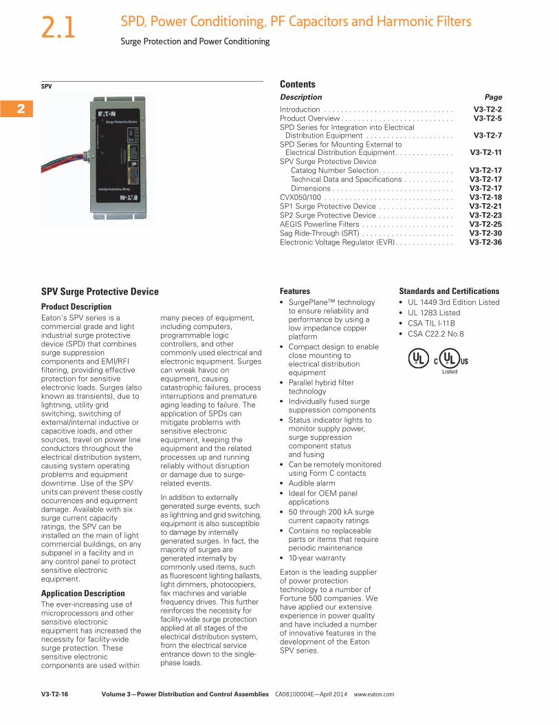
SPV Surge Protective DeviceProduct DescriptionEaton’s SPV series is a commercial grade and light industrial surge protective device (SPD) that combines surge suppression components and EMI/RFI filtering, providing effective protection for sensitive electronic loads. Surges (also known as transients), due to lightning, utility grid switching, switching of external/internal inductive or capacitive loads, and other sources, travel on power line conductors throughout the electrical distribution system, causing system operating problems and equipment downtime. Use of the SPV units can prevent these costly occurrences and equipment damage. Available with six surge current capacity ratings, the SPV can be installed on the main of light commercial buildings, on any subpanel in a facility and in any control panel to protect sensitive electronic equipment.
Application DescriptionThe ever-increasing use of microprocessors and other sensitive electronic equipment has increased the necessity for facility-wide surge protection. These sensitive electronic components are used within
many pieces of equipment, including computers, programmable logic controllers, and other commonly used electrical and electronic equipment. Surges can wreak havoc on equipment, causing catastrophic failures, process interruptions and premature aging leading to failure. The application of SPDs can mitigate problems with sensitive electronic equipment, keeping the equipment and the related processes up and running reliably without disruption or damage due to surge-related events.
In addition to externally generated surge events, such as lightning and grid switching, equipment is also susceptible to damage by internally generated surges. In fact, the majority of surges are generated internally by commonly used items, such as fluorescent lighting ballasts, light dimmers, photocopiers, fax machines and variable frequency drives. This further reinforces the necessity for facility-wide surge protection applied at all stages of the electrical distribution system, from the electrical service entrance down to the single-phase loads.
Features● SurgePlane™ technology
to ensure reliability and performance by using a low impedance copper platform
● Compact design to enable close mounting to electrical distribution equipment
● Parallel hybrid filter technology
● Individually fused surge suppression components
● Status indicator lights to monitor supply power, surge suppression component status and fusing
● Can be remotely monitored using Form C contacts
● Audible alarm● Ideal for OEM panel
applications● 50 through 200 kA surge
current capacity ratings● Contains no replaceable
parts or items that require periodic maintenance
● 10-year warranty
Eaton is the leading supplier of power protection technology to a number of Fortune 500 companies. We have applied our extensive experience in power quality and have included a number of innovative features in the development of the Eaton SPV series.
Standards and Certifications● UL 1449 3rd Edition Listed● UL 1283 Listed● CSA TIL I-11B● CSA C22.2 No.8
Volume 3—Power Distribution and Control Assemblies CA08100004E—April 2014 www.eaton.com V3-T2-17
2
2
2
2
2
2
2
2
2
2
2
2
2
2
2
2
2
2
2
2
2
2
2
2
2
2
2
2
2
2
2.1SPD, Power Conditioning, PF Capacitors and Harmonic Filters
Surge Protection and Power Conditioning
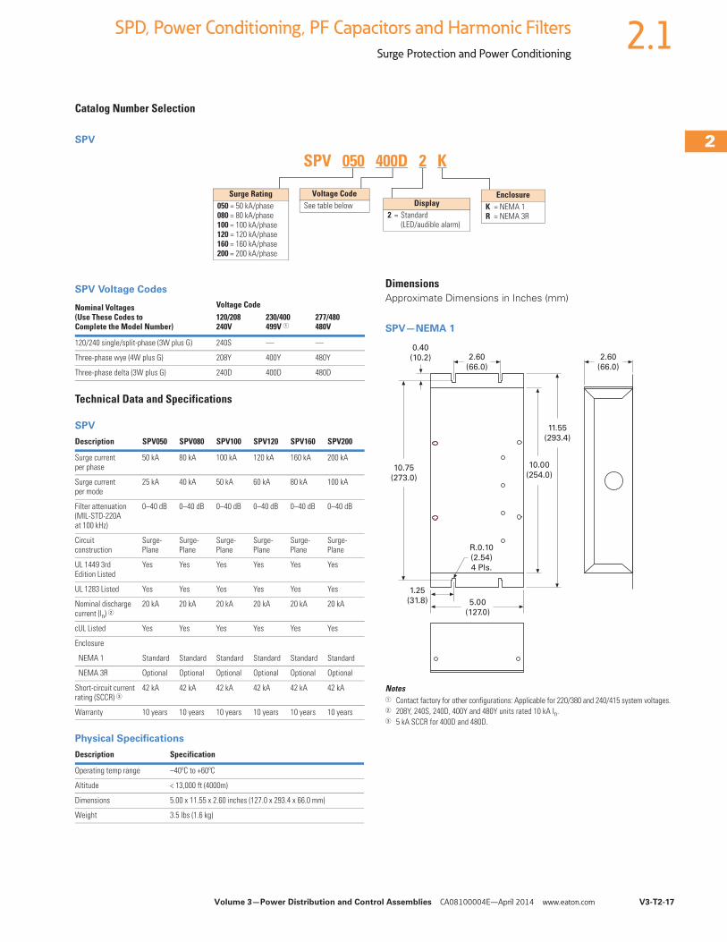
Catalog Number Selection
SPV
SPV Voltage Codes
Technical Data and Specifications
SPV
Physical Specifications
Nominal Voltages (Use These Codes to Complete the Model Number)
Voltage Code120/208240V
230/400499V 1
277/480480V
120/240 single/split-phase (3W plus G) 240S — —
Three-phase wye (4W plus G) 208Y 400Y 480Y
Three-phase delta (3W plus G) 240D 400D 480D
Surge Rating050 = 50 kA/phase080 = 80 kA/phase100 = 100 kA/phase120 = 120 kA/phase160 = 160 kA/phase200 = 200 kA/phase
EnclosureK = NEMA 1 R = NEMA 3R
Voltage Code See table below Display
2 = Standard(LED/audible alarm)
SPV 050 400D 2 K
Description SPV050 SPV080 SPV100 SPV120 SPV160 SPV200
Surge current per phase
50 kA 80 kA 100 kA 120 kA 160 kA 200 kA
Surge current per mode
25 kA 40 kA 50 kA 60 kA 80 kA 100 kA
Filter attenuation(MIL-STD-220A at 100 kHz)
0–40 dB 0–40 dB 0–40 dB 0–40 dB 0–40 dB 0–40 dB
Circuit construction
Surge- Plane
Surge- Plane
Surge- Plane
Surge- Plane
Surge- Plane
Surge- Plane
UL 1449 3rd Edition Listed
Yes Yes Yes Yes Yes Yes
UL 1283 Listed Yes Yes Yes Yes Yes Yes
Nominal discharge current (ln) 2
20 kA 20 kA 20 kA 20 kA 20 kA 20 kA
cUL Listed Yes Yes Yes Yes Yes Yes
Enclosure
NEMA 1 Standard Standard Standard Standard Standard Standard
NEMA 3R Optional Optional Optional Optional Optional Optional
Short-circuit current rating (SCCR) 3
42 kA 42 kA 42 kA 42 kA 42 kA 42 kA
Warranty 10 years 10 years 10 years 10 years 10 years 10 years
Description Specification
Operating temp range –40ºC to +60ºC
Altitude < 13,000 ft (4000m)
Dimensions 5.00 x 11.55 x 2.60 inches (127.0 x 293.4 x 66.0 mm)
Weight 3.5 lbs (1.6 kg)
DimensionsApproximate Dimensions in Inches (mm)
SPV—NEMA 1
Notes1 Contact factory for other configurations: Applicable for 220/380 and 240/415 system voltages.2 208Y, 240S, 240D, 400Y and 480Y units rated 10 kA In.3 5 kA SCCR for 400D and 480D.
1.25
(31.8) 5.00
(127.0)
2.60
(66.0)
2.60
(66.0)
10.75
(273.0)
11.55
(293.4)
10.00
(254.0)
0.40
(10.2)
R.0.10
(2.54)
4 Pls.
V3-T2-18 Volume 3—Power Distribution and Control Assemblies CA08100004E—April 2014 www.eaton.com
2
2
2
2
2
2
2
2
2
2
2
2
2
2
2
2
2
2
2
2
2
2
2
2
2
2
2
2
2
2
2.1 SPD, Power Conditioning, PF Capacitors and Harmonic Filters
Surge Protection and Power Conditioning
CVX050/100 ContentsDescription Page
Introduction . . . . . . . . . . . . . . . . . . . . . . . . . . . . . . . V3-T2-2Product Overview . . . . . . . . . . . . . . . . . . . . . . . . . . . V3-T2-5
SPD Series for Integration into Electrical Distribution Equipment . . . . . . . . . . . . . . . . . . . . . V3-T2-7
SPD Series for Mounting External to Electrical Distribution Equipment. . . . . . . . . . . . . . V3-T2-11
SPV Surge Protective Device . . . . . . . . . . . . . . . . . . V3-T2-16CVX050/100
Catalog Number Selection . . . . . . . . . . . . . . . . . V3-T2-19
Technical Data and Specifications . . . . . . . . . . . . V3-T2-19
Dimensions . . . . . . . . . . . . . . . . . . . . . . . . . . . . V3-T2-20
SP1 Surge Protective Device . . . . . . . . . . . . . . . . . . V3-T2-21SP2 Surge Protective Device . . . . . . . . . . . . . . . . . . V3-T2-23AEGIS Powerline Filters . . . . . . . . . . . . . . . . . . . . . . V3-T2-25
Sag Ride-Through (SRT) . . . . . . . . . . . . . . . . . . . . . . V3-T2-30Electronic Voltage Regulator (EVR) . . . . . . . . . . . . . . V3-T2-36
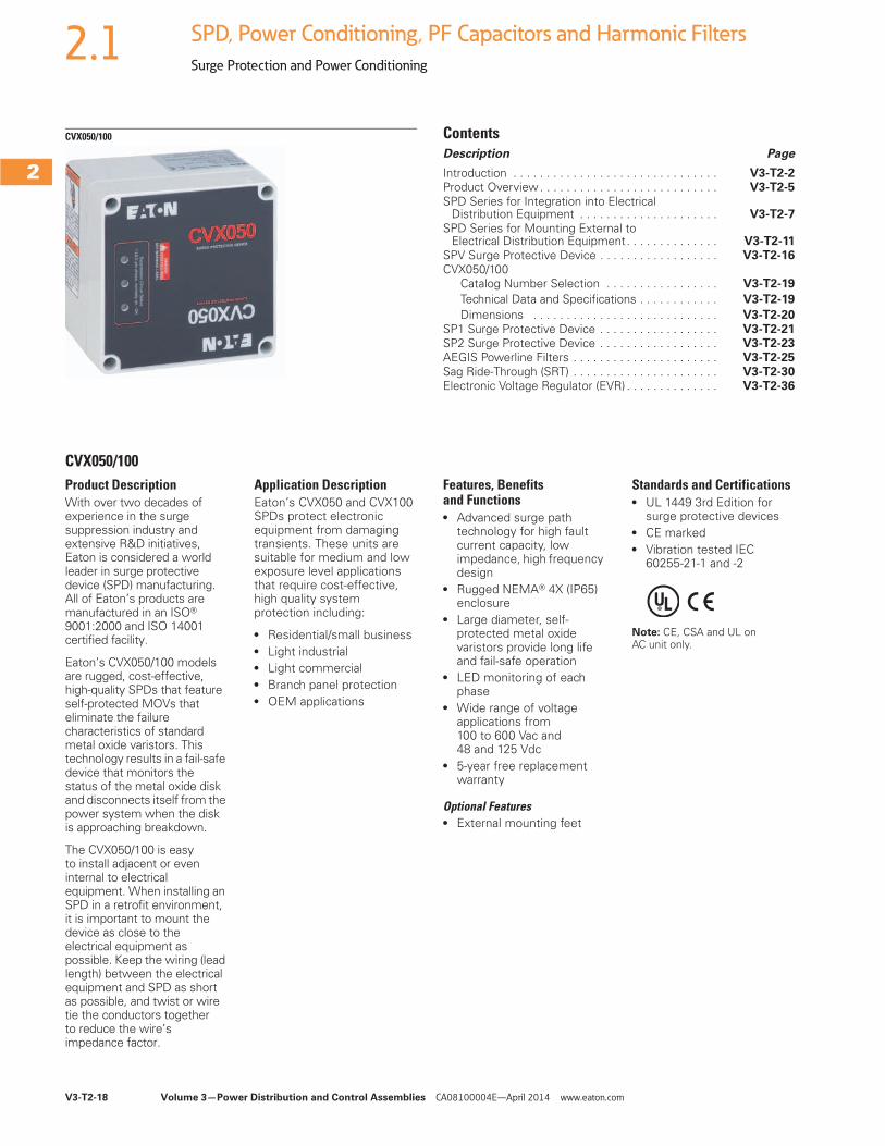
CVX050/100Product DescriptionWith over two decades of experience in the surge suppression industry and extensive R&D initiatives, Eaton is considered a world leader in surge protective device (SPD) manufacturing. All of Eaton’s products are manufactured in an ISO® 9001:2000 and ISO 14001 certified facility.
Eaton’s CVX050/100 models are rugged, cost-effective, high-quality SPDs that feature self-protected MOVs that eliminate the failure characteristics of standard metal oxide varistors. This technology results in a fail-safe device that monitors the status of the metal oxide disk and disconnects itself from the power system when the disk is approaching breakdown.
The CVX050/100 is easy to install adjacent or even internal to electrical equipment. When installing an SPD in a retrofit environment, it is important to mount the device as close to the electrical equipment as possible. Keep the wiring (lead length) between the electrical equipment and SPD as short as possible, and twist or wire tie the conductors together to reduce the wire’s impedance factor.
Application DescriptionEaton’s CVX050 and CVX100 SPDs protect electronic equipment from damaging transients. These units are suitable for medium and low exposure level applications that require cost-effective, high quality system protection including:
● Residential/small business● Light industrial● Light commercial● Branch panel protection● OEM applications
Features, Benefits and Functions● Advanced surge path
technology for high fault current capacity, low impedance, high frequency design
● Rugged NEMA® 4X (IP65) enclosure
● Large diameter, self-protected metal oxide varistors provide long life and fail-safe operation
● LED monitoring of each phase
● Wide range of voltage applications from 100 to 600 Vac and 48 and 125 Vdc
● 5-year free replacement warranty
Optional Features● External mounting feet
Standards and Certifications● UL 1449 3rd Edition for
surge protective devices● CE marked● Vibration tested IEC
60255-21-1 and -2
Note: CE, CSA and UL on AC unit only.
Volume 3—Power Distribution and Control Assemblies CA08100004E—April 2014 www.eaton.com V3-T2-19
2
2
2
2
2
2
2
2
2
2
2
2
2
2
2
2
2
2
2
2
2
2
2
2
2
2
2
2
2
2
2.1SPD, Power Conditioning, PF Capacitors and Harmonic Filters
Surge Protection and Power Conditioning
Catalog Number Selection
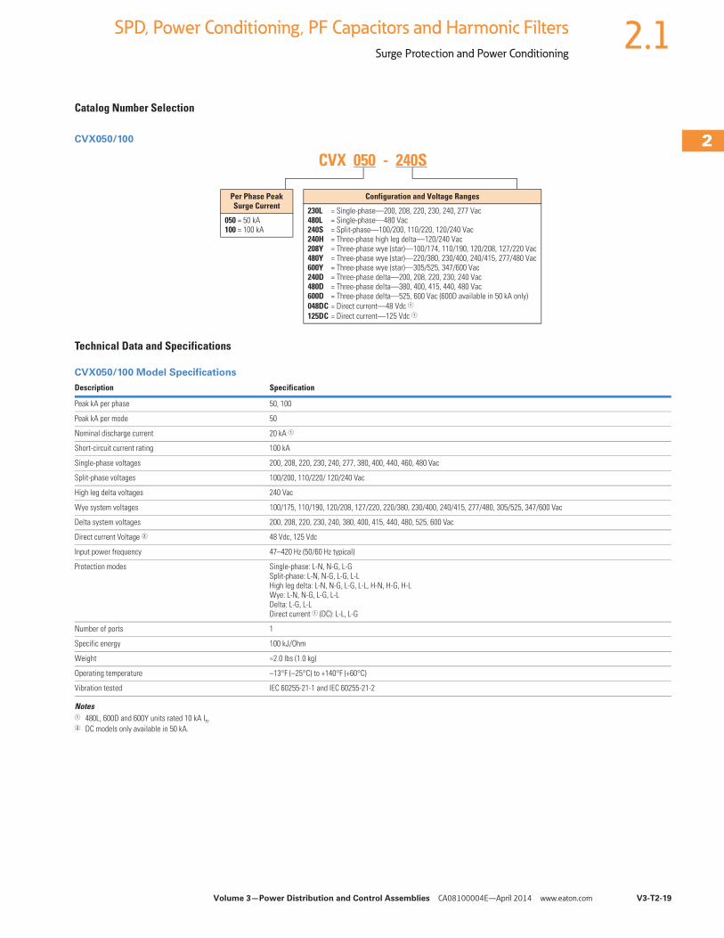
CVX050/100
Technical Data and Specifications
CVX050/100 Model Specifications
Notes1 480L, 600D and 600Y units rated 10 kA In.2 DC models only available in 50 kA.
Description Specification
Peak kA per phase 50, 100
Peak kA per mode 50
Nominal discharge current 20 kA 1
Short-circuit current rating 100 kA
Single-phase voltages 200, 208, 220, 230, 240, 277, 380, 400, 440, 460, 480 Vac
Split-phase voltages 100/200, 110/220/ 120/240 Vac
High leg delta voltages 240 Vac
Wye system voltages 100/175, 110/190, 120/208, 127/220, 220/380, 230/400, 240/415, 277/480, 305/525, 347/600 Vac
Delta system voltages 200, 208, 220, 230, 240, 380, 400, 415, 440, 480, 525, 600 Vac
Direct current Voltage 2 48 Vdc, 125 Vdc
Input power frequency 47–420 Hz (50/60 Hz typical)
Protection modes Single-phase: L-N, N-G, L-GSplit-phase: L-N, N-G, L-G, L-LHigh leg delta: L-N, N-G, L-G, L-L, H-N, H-G, H-LWye: L-N, N-G, L-G, L-LDelta: L-G, L-LDirect current 1 (DC): L-L, L-G
Number of ports 1
Specific energy 100 kJ/Ohm
Weight ≈2.0 lbs (1.0 kg)
Operating temperature –13°F (–25°C) to +140°F (+60°C)
Vibration tested IEC 60255-21-1 and IEC 60255-21-2
Per Phase PeakSurge Current
050 = 50 kA100 = 100 kA
Configuration and Voltage Ranges
230L = Single-phase—200, 208, 220, 230, 240, 277 Vac480L = Single-phase—480 Vac240S = Split-phase—100/200, 110/220, 120/240 Vac240H = Three-phase high leg delta—120/240 Vac208Y = Three-phase wye (star)—100/174, 110/190, 120/208, 127/220 Vac480Y = Three-phase wye (star)—220/380, 230/400, 240/415, 277/480 Vac600Y = Three-phase wye (star)—305/525, 347/600 Vac240D = Three-phase delta—200, 208, 220, 230, 240 Vac480D = Three-phase delta—380, 400, 415, 440, 480 Vac600D = Three-phase delta—525, 600 Vac (600D available in 50 kA only)048DC = Direct current—48 Vdc 1125DC = Direct current—125 Vdc 1
CVX 050 - 240S
V3-T2-20 Volume 3—Power Distribution and Control Assemblies CA08100004E—April 2014 www.eaton.com
2
2
2
2
2
2
2
2
2
2
2
2
2
2
2
2
2
2
2
2
2
2
2
2
2
2
2
2
2
2
2.1 SPD, Power Conditioning, PF Capacitors and Harmonic Filters
Surge Protection and Power Conditioning
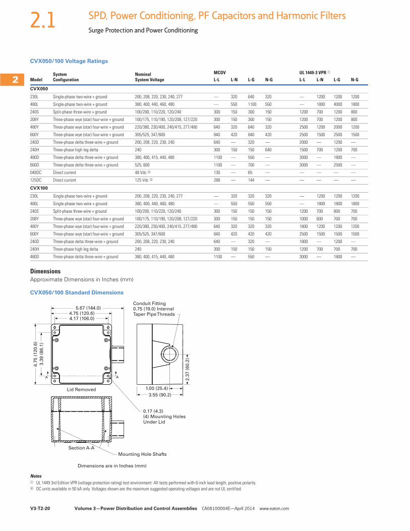
CVX050/100 Voltage Ratings
DimensionsApproximate Dimensions in Inches (mm)
CVX050/100 Standard Dimensions
Notes1 UL 1449 3rd Edition VPR (voltage protection rating) test environment: All tests performed with 6-inch lead length, positive polarity.2 DC units available in 50 kA only. Voltages shown are the maximum suggested operating voltages and are not UL certified.
ModelSystem Configuration
Nominal System Voltage
MCOV UL 1449-3 VPR 1
L-L L-N L-G N-G L-L L-N L-G N-G
CVX050
230L Single-phase two-wire + ground 200, 208, 220, 230, 240, 277 — 320 640 320 — 1200 1200 1200
480L Single-phase two-wire + ground 380, 400, 440, 460, 480 — 550 1100 550 — 1800 4000 1800
240S Split-phase three-wire + ground 100/200, 110/220, 120/240 300 150 300 150 1200 700 1200 800
208Y Three-phase wye (star) four-wire + ground 100/175, 110/190, 120/208, 127/220 300 150 300 150 1200 700 1200 800
480Y Three-phase wye (star) four-wire + ground 220/380, 230/400, 240/415, 277/480 640 320 640 320 2500 1200 2000 1200
600Y Three-phase wye (star) four-wire + ground 305/525, 347/600 840 420 840 420 2500 1500 2500 1500
240D Three-phase delta three-wire + ground 200, 208, 220, 230, 240 640 — 320 — 2000 — 1200 —
240H Three-phase high leg delta 240 300 150 150 640 1500 700 1200 700
480D Three-phase delta three-wire + ground 380, 400, 415, 440, 480 1100 — 550 — 3000 — 1800 —
600D Three-phase delta three-wire + ground 525, 600 1100 — 700 — 3000 — 2500 —
048DC Direct current 48 Vdc 2 130 — 65 — — — — —
125DC Direct current 125 Vdc 2 288 — 144 — — — — —
CVX100
230L Single-phase two-wire + ground 200, 208, 220, 230, 240, 277 — 320 320 320 — 1200 1200 1200
480L Single-phase two-wire + ground 380, 400, 440, 460, 480 — 550 550 550 — 1800 1800 1800
240S Split-phase three-wire + ground 100/200, 110/220, 120/240 300 150 150 150 1200 700 800 700
208Y Three-phase wye (star) four-wire + ground 100/175, 110/190, 120/208, 127/220 300 150 150 150 1000 600 700 700
480Y Three-phase wye (star) four-wire + ground 220/380, 230/400, 240/415, 277/480 640 320 320 320 1800 1200 1200 1200
600Y Three-phase wye (star) four-wire + ground 305/525, 347/600 840 420 420 420 2500 1500 1500 1500
240D Three-phase delta three-wire + ground 200, 208, 220, 230, 240 640 — 320 — 1800 — 1200 —
240H Three-phase high leg delta 240 300 150 150 150 1200 700 700 700
480D Three-phase delta three-wire + ground 380, 400, 415, 440, 480 1100 — 550 — 3000 — 1800 —
AA
Mounting Hole Shafts
5.67 (144.0)
4.7
5 (
12
0.6
)
2.3
7 (
60
.2)
1.00 (25.4)
3.55 (90.2)
3.3
9 (
86
.1)
4.75 (120.6)4.17 (106.0)
Conduit Fitting0.75 (19.0) InternalTaper Pipe Threads
0.17 (4.3)(4) Mounting HolesUnder Lid
Lid Removed
Section A-A
Dimensions are in Inches (mm)
Volume 3—Power Distribution and Control Assemblies CA08100004E—April 2014 www.eaton.com V3-T2-21
2
2
2
2
2
2
2
2
2
2
2
2
2
2
2
2
2
2
2
2
2
2
2
2
2
2
2
2
2
2
2.1SPD, Power Conditioning, PF Capacitors and Harmonic Filters
Surge Protection and Power Conditioning
SP1 Surge Protective Device ContentsDescription Page
Introduction. . . . . . . . . . . . . . . . . . . . . . . . . . . . . . . V3-T2-2Product Overview . . . . . . . . . . . . . . . . . . . . . . . . . . V3-T2-5
SPD Series for Integration into Electrical Distribution Equipment . . . . . . . . . . . . . . . . . . . . V3-T2-7
SPD Series for Mounting External to Electrical Distribution Equipment . . . . . . . . . . . . . V3-T2-11
SPV Surge Protective Device . . . . . . . . . . . . . . . . . V3-T2-16CVX050/100 . . . . . . . . . . . . . . . . . . . . . . . . . . . . . . V3-T2-18SP1 Surge Protective Device
Catalog Number Selection. . . . . . . . . . . . . . . . . V3-T2-22Technical Data and Specifications . . . . . . . . . . . V3-T2-22Dimensions . . . . . . . . . . . . . . . . . . . . . . . . . . . . V3-T2-22
SP2 Surge Protective Device . . . . . . . . . . . . . . . . . V3-T2-23AEGIS Powerline Filters . . . . . . . . . . . . . . . . . . . . . V3-T2-25Sag Ride-Through (SRT) . . . . . . . . . . . . . . . . . . . . . V3-T2-30
Electronic Voltage Regulator (EVR) . . . . . . . . . . . . . V3-T2-36
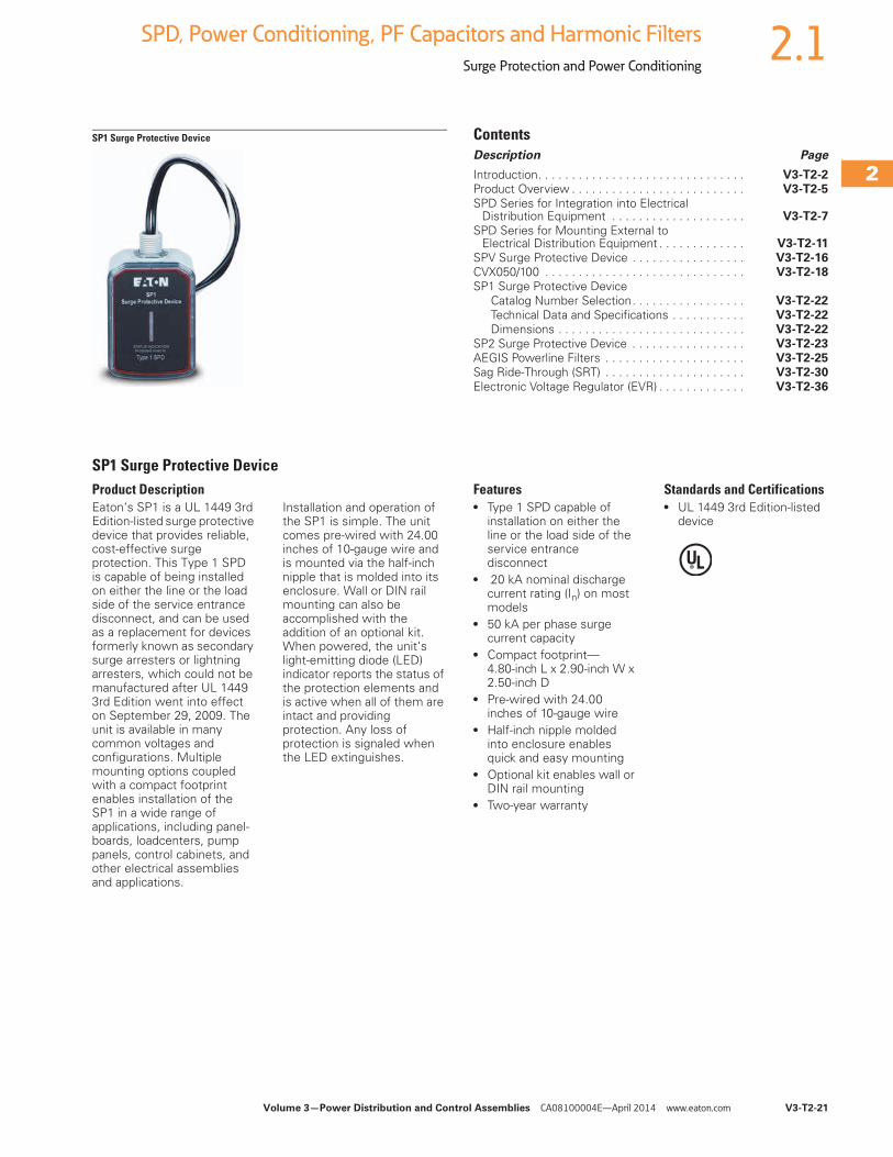
SP1 Surge Protective DeviceProduct DescriptionEaton‘s SP1 is a UL 1449 3rd Edition-listed surge protective device that provides reliable, cost-effective surge protection. This Type 1 SPD is capable of being installed on either the line or the load side of the service entrance disconnect, and can be used as a replacement for devices formerly known as secondary surge arresters or lightning arresters, which could not be manufactured after UL 1449 3rd Edition went into effect on September 29, 2009. The unit is available in many common voltages and configurations. Multiple mounting options coupled with a compact footprint enables installation of the SP1 in a wide range of applications, including panel-boards, loadcenters, pump panels, control cabinets, and other electrical assemblies and applications.
Installation and operation of the SP1 is simple. The unit comes pre-wired with 24.00 inches of 10-gauge wire and is mounted via the half-inch nipple that is molded into its enclosure. Wall or DIN rail mounting can also be accomplished with the addition of an optional kit. When powered, the unit‘s light-emitting diode (LED) indicator reports the status of the protection elements and is active when all of them are intact and providing protection. Any loss of protection is signaled when the LED extinguishes.
Features● Type 1 SPD capable of
installation on either the line or the load side of the service entrance disconnect
● 20 kA nominal discharge current rating (In) on most models
● 50 kA per phase surge current capacity
● Compact footprint—4.80-inch L x 2.90-inch W x 2.50-inch D
● Pre-wired with 24.00 inches of 10-gauge wire
● Half-inch nipple molded into enclosure enables quick and easy mounting
● Optional kit enables wall or DIN rail mounting
● Two-year warranty
Standards and Certifications● UL 1449 3rd Edition-listed
device
V3-T2-22 Volume 3—Power Distribution and Control Assemblies CA08100004E—April 2014 www.eaton.com
2
2
2
2
2
2
2
2
2
2
2
2
2
2
2
2
2
2
2
2
2
2
2
2
2
2
2
2
2
2
2.1 SPD, Power Conditioning, PF Capacitors and Harmonic Filters
Surge Protection and Power Conditioning
Catalog Number Selection
SP1
Technical Data and Specifications
SP1
ANSI/UL 1449 3rd Edition Voltage Protection Ratings
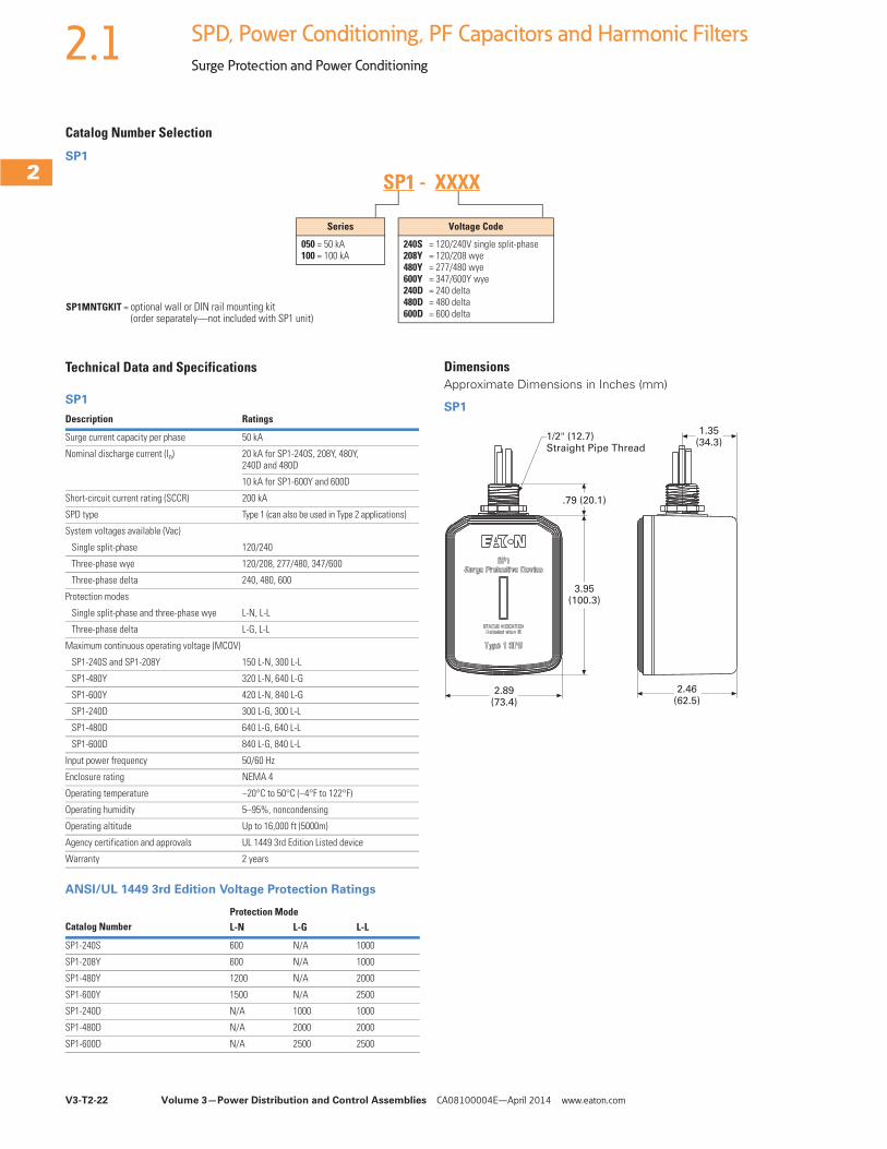
Series
050 = 50 kA100 = 100 kA
Voltage Code
240S = 120/240V single split-phase208Y = 120/208 wye480Y = 277/480 wye600Y = 347/600Y wye240D = 240 delta480D = 480 delta600D = 600 delta
SP1 - XXXX
SP1MNTGKIT = optional wall or DIN rail mounting kit (order separately—not included with SP1 unit)
Description Ratings
Surge current capacity per phase 50 kA
Nominal discharge current (In) 20 kA for SP1-240S, 208Y, 480Y, 240D and 480D
10 kA for SP1-600Y and 600D
Short-circuit current rating (SCCR) 200 kA
SPD type Type 1 (can also be used in Type 2 applications)
System voltages available (Vac)
Single split-phase 120/240
Three-phase wye 120/208, 277/480, 347/600
Three-phase delta 240, 480, 600
Protection modes
Single split-phase and three-phase wye L-N, L-L
Three-phase delta L-G, L-L
Maximum continuous operating voltage (MCOV)
SP1-240S and SP1-208Y 150 L-N, 300 L-L
SP1-480Y 320 L-N, 640 L-G
SP1-600Y 420 L-N, 840 L-G
SP1-240D 300 L-G, 300 L-L
SP1-480D 640 L-G, 640 L-L
SP1-600D 840 L-G, 840 L-L
Input power frequency 50/60 Hz
Enclosure rating NEMA 4
Operating temperature –20°C to 50°C (–4°F to 122°F)
Operating humidity 5–95%, noncondensing
Operating altitude Up to 16,000 ft (5000m)
Agency certification and approvals UL 1449 3rd Edition Listed device
Warranty 2 years
Catalog NumberProtection ModeL-N L-G L-L
SP1-240S 600 N/A 1000
SP1-208Y 600 N/A 1000
SP1-480Y 1200 N/A 2000
SP1-600Y 1500 N/A 2500
SP1-240D N/A 1000 1000
SP1-480D N/A 2000 2000
SP1-600D N/A 2500 2500
DimensionsApproximate Dimensions in Inches (mm)
SP1
1/2" (12.7) Straight Pipe Thread
1.35(34.3)
.79 (20.1)
3.95(100.3)
2.89(73.4)
2.46(62.5)
Volume 3—Power Distribution and Control Assemblies CA08100004E—April 2014 www.eaton.com V3-T2-23
2
2
2
2
2
2
2
2
2
2
2
2
2
2
2
2
2
2
2
2
2
2
2
2
2
2
2
2
2
2
2.1SPD, Power Conditioning, PF Capacitors and Harmonic Filters
Surge Protection and Power Conditioning
Surge Protection for Light Commercial and UL 508A Panel Applications
SP2 Surge Protective Device ContentsDescription Page
Introduction. . . . . . . . . . . . . . . . . . . . . . . . . . . . . . . V3-T2-2Product Overview . . . . . . . . . . . . . . . . . . . . . . . . . . V3-T2-5
SPD Series for Integration into Electrical Distribution Equipment . . . . . . . . . . . . . . . . . . . . V3-T2-7
SPD Series for Mounting External to Electrical Distribution Equipment . . . . . . . . . . . . . V3-T2-11
SPV Surge Protective Device . . . . . . . . . . . . . . . . . V3-T2-16CVX050/100 . . . . . . . . . . . . . . . . . . . . . . . . . . . . . . V3-T2-18SP1 Surge Protective Device . . . . . . . . . . . . . . . . . V3-T2-21
SP2 Surge Protective DeviceProduct Selection. . . . . . . . . . . . . . . . . . . . . . . . V3-T2-24Technical Data and Specifications . . . . . . . . . . . V3-T2-24
Dimensions . . . . . . . . . . . . . . . . . . . . . . . . . . . . V3-T2-24AEGIS Powerline Filters . . . . . . . . . . . . . . . . . . . . . V3-T2-25Sag Ride-Through (SRT) . . . . . . . . . . . . . . . . . . . . . V3-T2-30
Electronic Voltage Regulator (EVR) . . . . . . . . . . . . . V3-T2-36
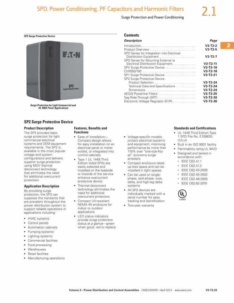
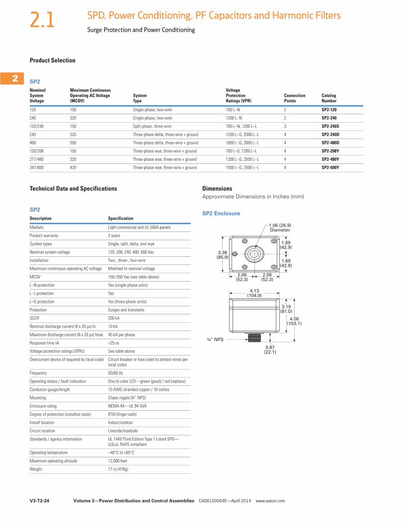
SP2 Surge Protective DeviceProduct DescriptionThe SP2 provides basic surge protection for light commercial electrical systems and OEM equipment requirements. The SP2 is available in the most popular voltage and system configurations and delivers superior surge protection using MOV thermal disconnect technology that eliminates the need for additional overcurrent protection.
Application DescriptionBy providing surge protection, the SP2 can suppress the transients that are prevalent throughout the power distribution system to support reliable operations in applications including:
● HVAC systems● Control panels● Automation cabinets● Pumping systems● Lighting systems● Commercial facilities● Food processing● Warehouses ● Retail facilities ● Manufacturing operations
Features, Benefits and Functions● Ease of installation—
Compact design allows for easy installation on an electrical panel or meter socket, or integrated into control cabinets
● Type 1 UL 1449 Third Edition listed SP2s are easily selected and installed on the loadside or lineside of the service entrance overcurrent protective device
● Thermal disconnect technology eliminates the need for additional overcurrent protection
● Compact UV-resistant NEMA 4X enclosure for indoor or outdoor applications
● LED status indicators provide surge protection status at a glance—green when good, red to replace
● Voltage-specific models protect electrical systems and equipment, improving performance by more than 110% over “one-size-fits-all” economy surge arresters
● Compact enclosure takes up less space and can be installed in tight spaces
● Can be used on single-phase, split-phase, wye, delta, and high-leg delta systems
● All SP2 devices are individually marked with a serial number for easy tracking and identification
● Two-year warranty
Standards and Certifications● UL 1449 Third Edition Type
1 SPD File No. E109835, cULus
● Built in an ISO 9001 facility● Flammability rating UL 94VO● Designed and tested in
accordance with:● IEEE C62.41.1● IEEE C62.41.2● IEEE C62.43-2005● IEEE C62.45-2002● IEEE C62.48-2005● IEEE C62.62-2010
V3-T2-24 Volume 3—Power Distribution and Control Assemblies CA08100004E—April 2014 www.eaton.com
2
2
2
2
2
2
2
2
2
2
2
2
2
2
2
2
2
2
2
2
2
2
2
2
2
2
2
2
2
2
2.1 SPD, Power Conditioning, PF Capacitors and Harmonic Filters
Surge Protection and Power Conditioning
Product Selection
SP2
Technical Data and Specifications
SP2
DimensionsApproximate Dimensions in Inches (mm)
SP2 Enclosure
Nominal System Voltage
Maximum ContinuousOperating AC Voltage (MCOV)
SystemType
Voltage Protection Ratings (VPR)
Connection Points
Catalog Number
120 150 Single-phase, two-wire 700 L–N 2 SP2-120
240 320 Single-phase, two-wire 1200 L–N 2 SP2-240
120/240 150 Split-phase, three-wire 700 L–N, 1200 L–L 3 SP2-240S
240 320 Three-phase delta, three-wire + ground 1200 L–G, 2500 L–L 4 SP2-240D
480 550 Three-phase delta, three-wire + ground 1800 L–G, 3000 L–L 4 SP2-480D
120/208 150 Three-phase wye, three-wire + ground 700 L–G, 1200 L–L 4 SP2-208Y
277/480 320 Three-phase wye, three-wire + ground 1200 L–G, 2500 L–L 4 SP2-480Y
347/600 420 Three-phase wye, three-wire + ground 1500 L–G, 2500 L–L 4 SP2-600Y
Description Specification
Markets Light commercial and UL 508A panels
Product warranty 2 years
System types Single, split, delta, and wye
Nominal system voltage 120, 208, 240, 480, 600 Vac
Installation Two-, three-, four-wire
Maximum continuous operating AC voltage Matched to nominal voltage
MCOV 150–550 Vac (see table above)
L–N protection Yes (single-phase units)
L–L protection Yes
L–G protection Yes (three-phase units)
Protection Surges and transients
SCCR 200 kA
Nominal discharge current (8 x 20 μs) In 10 kA
Maximum discharge current (8 x 20 μs) Imax 45 kA per phase
Response time tA <25 ns
Voltage protection ratings (VPRs) See table above
Overcurrent device (if required by local code) Circuit breaker or fuse sized to protect wires per local codes
Frequency 50/60 Hz
Operating status / fault indication One bi-color LED—green (good) / red (replace)
Conductor gauge/length 10 AWG stranded copper / 18 inches
Mounting Chase nipple (¾” NPS)
Enclosure rating NEMA 4X—UL 94-5VA
Degree of protection (installed state) IP20 (finger-safe)
Install location Indoor/outdoor
Circuit location Lineside/loadside
Standards / agency information UL 1449 Third Edition Type 1 Listed SPD—cULus, RoHS compliant
Operating temperature –40°C to +65°C
Maximum operating altitude 12,000 feet
Weight 17 oz (476g)
3.38(85.9)
1.69(42.9)
1.69(42.9)
3.19(81.0)
4.06(103.1)
0.87(22.1)
4.13(104.9)
2.06(52.3)
2.06(52.3)
1.06 (26.9)Diameter
¾" NPS
Volume 3—Power Distribution and Control Assemblies CA08100004E—April 2014 www.eaton.com V3-T2-25
2
2
2
2
2
2
2
2
2
2
2
2
2
2
2
2
2
2
2
2
2
2
2
2
2
2
2
2
2
2
2.1SPD, Power Conditioning, PF Capacitors and Harmonic Filters
Surge Protection and Power Conditioning
AEGIS Solutions ContentsDescription Page
Introduction. . . . . . . . . . . . . . . . . . . . . . . . . . . . . . . V3-T2-2Product Overview . . . . . . . . . . . . . . . . . . . . . . . . . . V3-T2-5
SPD Series for Integration into Electrical Distribution Equipment . . . . . . . . . . . . . . . . . . . . V3-T2-7
SPD Series for Mounting External to Electrical Distribution Equipment . . . . . . . . . . . . . V3-T2-11
SPV Surge Protective Device . . . . . . . . . . . . . . . . . V3-T2-16CVX050/100 . . . . . . . . . . . . . . . . . . . . . . . . . . . . . . V3-T2-18SP1 Surge Protective Device . . . . . . . . . . . . . . . . . V3-T2-21
SP2 Surge Protective Device . . . . . . . . . . . . . . . . . V3-T2-23AEGIS Powerline Filters
Features, Benefits and Functions . . . . . . . . . . . V3-T2-26
Standards and Certifications . . . . . . . . . . . . . . . V3-T2-27Catalog Number Selection. . . . . . . . . . . . . . . . . V3-T2-27Technical Data and Specifications . . . . . . . . . . . V3-T2-28
Sag Ride-Through (SRT) . . . . . . . . . . . . . . . . . . . . . V3-T2-30Electronic Voltage Regulator (EVR) . . . . . . . . . . . . . V3-T2-36
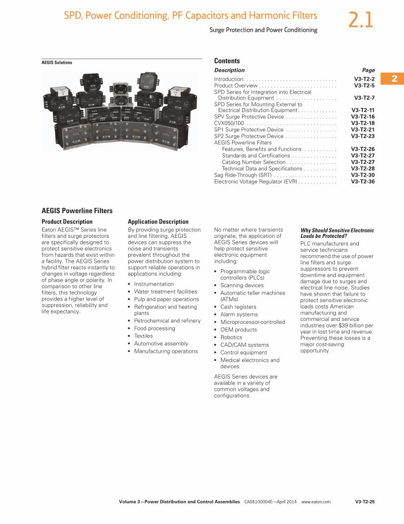
AEGIS Powerline FiltersProduct DescriptionEaton AEGIS™ Series line filters and surge protectors are specifically designed to protect sensitive electronics from hazards that exist within a facility. The AEGIS Series hybrid filter reacts instantly to changes in voltage regardless of phase angle or polarity. In comparison to other line filters, this technology provides a higher level of suppression, reliability and life expectancy.
Application DescriptionBy providing surge protection and line filtering, AEGIS devices can suppress the noise and transients prevalent throughout the power distribution system to support reliable operations in applications including:
● Instrumentation● Water treatment facilities● Pulp and paper operations● Refrigeration and heating
plants● Petrochemical and refinery ● Food processing● Textiles● Automotive assembly● Manufacturing operations
No matter where transients originate, the application of AEGIS Series devices will help protect sensitive electronic equipment including:
● Programmable logic controllers (PLCs)
● Scanning devices● Automatic teller machines
(ATMs)● Cash registers● Alarm systems● Microprocessor-controlled● OEM products● Robotics● CAD/CAM systems● Control equipment● Medical electronics and
devices
AEGIS Series devices are available in a variety of common voltages and configurations.
Why Should Sensitive Electronic Loads be Protected?PLC manufacturers and service technicians recommend the use of power line filters and surge suppressors to prevent downtime and equipment damage due to surges and electrical line noise. Studies have shown that failure to protect sensitive electronic loads costs American manufacturing and commercial and service industries over $39 billion per year in lost time and revenue. Preventing these losses is a major cost-saving opportunity.
V3-T2-26 Volume 3—Power Distribution and Control Assemblies CA08100004E—April 2014 www.eaton.com
2
2
2
2
2
2
2
2
2
2
2
2
2
2
2
2
2
2
2
2
2
2
2
2
2
2
2
2
2
2
2.1 SPD, Power Conditioning, PF Capacitors and Harmonic Filters
Surge Protection and Power Conditioning
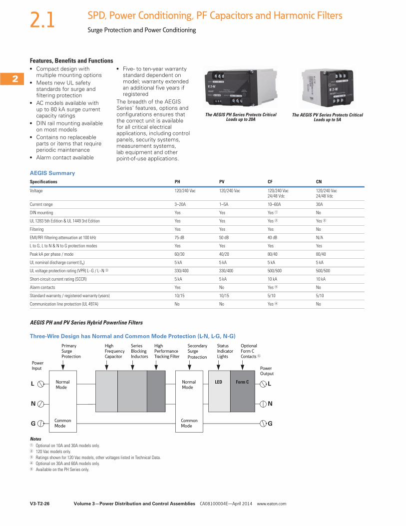
Features, Benefits and Functions● Compact design with
multiple mounting options● Meets new UL safety
standards for surge and filtering protection
● AC models available with up to 80 kA surge current capacity ratings
● DIN rail mounting available on most models
● Contains no replaceable parts or items that require periodic maintenance
● Alarm contact available
● Five- to ten-year warranty standard dependent on model; warranty extended an additional five years if registered
The breadth of the AEGIS Series’ features, options and configurations ensures that the correct unit is available for all critical electrical applications, including control panels, security systems, measurement systems, lab equipment and other point-of-use applications.
The AEGIS PH Series Protects Critical Loads up to 20A
The AEGIS PV Series Protects Critical Loads up to 5A
AEGIS Summary
AEGIS PH and PV Series Hybrid Powerline Filters
Three-Wire Design has Normal and Common Mode Protection (L-N, L-G, N-G)
Notes1 Optional on 10A and 30A models only.2 120 Vac models only.3 Ratings shown for 120 Vac models, other voltages listed in Technical Data.4 Optional on 30A and 60A models only.5 Available on the PH Series only.
Specifications PH PV CF CN
Voltage 120/240 Vac 120/240 Vac 120/240 Vac24/48 Vdc
120/240 Vac24/48 Vdc
Current range 3–20A 1–5A 10–60A 30A
DIN mounting Yes Yes Yes 1 No
UL 1283 5th Edition & UL 1449 3rd Edition Yes Yes Yes 2 Yes 2
Filtering Yes Yes Yes No
EMI/RFI filtering attenuation at 100 kHz 75 dB 50 dB 40 dB N/A
L to G, L to N & N to G protection modes Yes Yes Yes Yes
Peak kA per phase / mode 60/30 40/20 80/40 80/40
UL nominal discharge current (In) 5 kA 5 kA 5 kA 5 kA
UL voltage protection rating (VPR) L–G / L–N 3 330/400 330/400 500/500 500/500
Short-circuit current rating (SCCR) 5 kA 5 kA 10 kA 10 kA
Alarm contacts Yes No Yes 4 No
Standard warranty / registered warranty (years) 10/15 10/15 5/10 5/10
Communication line protection (UL 497A) No No Yes 4 No
PowerInput
Primary
Surge Protection
High
FrequencyCapacitor
Series
BlockingInductors
High
Performance Tracking Filter
Secondary
Surge
Protection
Status
IndicatorLights
Power
Output
Optional
Form C Contacts 5
L
N
G
L
N
G
Normal Mode
Common Mode
Normal Mode
Common Mode
LED Form C
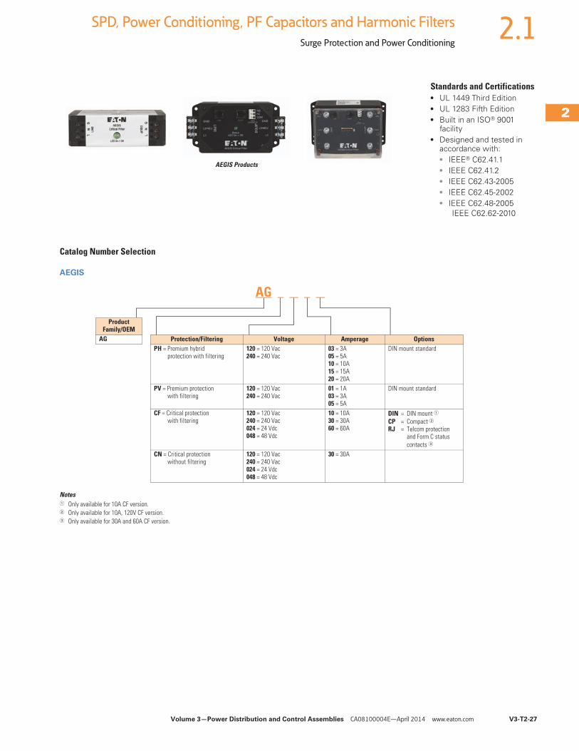
Volume 3—Power Distribution and Control Assemblies CA08100004E—April 2014 www.eaton.com V3-T2-27
2
2
2
2
2
2
2
2
2
2
2
2
2
2
2
2
2
2
2
2
2
2
2
2
2
2
2
2
2
2
2.1SPD, Power Conditioning, PF Capacitors and Harmonic Filters
Surge Protection and Power Conditioning
AEGIS Products
Standards and Certifications● UL 1449 Third Edition● UL 1283 Fifth Edition● Built in an ISO® 9001
facility● Designed and tested in
accordance with:● IEEE® C62.41.1● IEEE C62.41.2● IEEE C62.43-2005● IEEE C62.45-2002● IEEE C62.48-2005
IEEE C62.62-2010
Catalog Number Selection
AEGIS
Notes1 Only available for 10A CF version.2 Only available for 10A, 120V CF version.3 Only available for 30A and 60A CF version.
Protection/Filtering Voltage Amperage OptionsPH = Premium hybrid
protection with filtering120 = 120 Vac240 = 240 Vac
03 = 3A05 = 5A10 = 10A15 = 15A20 = 20A
DIN mount standard
PV = Premium protection with filtering
120 = 120 Vac240 = 240 Vac
01 = 1A03 = 3A05 = 5A
DIN mount standard
CF = Critical protection with filtering
120 = 120 Vac240 = 240 Vac024 = 24 Vdc048 = 48 Vdc
10 = 10A30 = 30A60 = 60A
DIN = DIN mount 1CP = Compact 2RJ = Telcom protection
and Form C status contacts 3
CN = Critical protection without filtering
120 = 120 Vac240 = 240 Vac024 = 24 Vdc048 = 48 Vdc
30 = 30A
Product Family/OEM
AG
AG
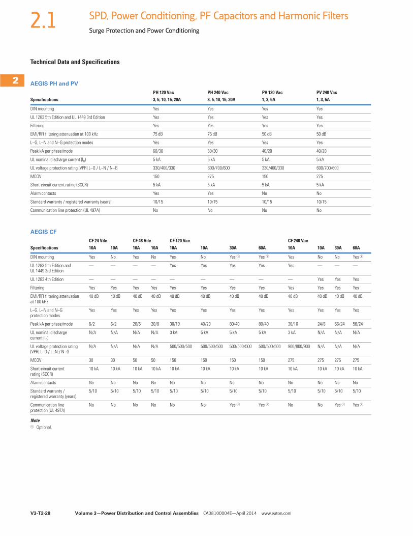
V3-T2-28 Volume 3—Power Distribution and Control Assemblies CA08100004E—April 2014 www.eaton.com
2
2
2
2
2
2
2
2
2
2
2
2
2
2
2
2
2
2
2
2
2
2
2
2
2
2
2
2
2
2
2.1 SPD, Power Conditioning, PF Capacitors and Harmonic Filters
Surge Protection and Power Conditioning
Technical Data and Specifications
AEGIS PH and PV
AEGIS CF
Note1 Optional.
PH 120 Vac PH 240 Vac PV 120 Vac PV 240 VacSpecifications 3, 5, 10, 15, 20A 3, 5, 10, 15, 20A 1, 3, 5A 1, 3, 5A
DIN mounting Yes Yes Yes Yes
UL 1283 5th Edition and UL 1449 3rd Edition Yes Yes Yes Yes
Filtering Yes Yes Yes Yes
EMI/RFI filtering attenuation at 100 kHz 75 dB 75 dB 50 dB 50 dB
L–G, L–N and N–G protection modes Yes Yes Yes Yes
Peak kA per phase/mode 60/30 60/30 40/20 40/20
UL nominal discharge current (In) 5 kA 5 kA 5 kA 5 kA
UL voltage protection rating (VPR) L–G / L–N / N–G 330/400/330 600/700/600 330/400/330 600/700/600
MCOV 150 275 150 275
Short-circuit current rating (SCCR) 5 kA 5 kA 5 kA 5 kA
Alarm contacts Yes Yes No No
Standard warranty / registered warranty (years) 10/15 10/15 10/15 10/15
Communication line protection (UL 497A) No No No No
SpecificationsCF 24 Vdc CF 48 Vdc CF 120 Vac CF 240 Vac10A 10A 10A 10A 10A 10A 30A 60A 10A 10A 30A 60A
DIN mounting Yes No Yes No Yes No Yes 1 Yes 1 Yes No No Yes 1
UL 1283 5th Edition and UL 1449 3rd Edition
— — — — Yes Yes Yes Yes Yes — — —
UL 1283 4th Edition — — — — — — — — — Yes Yes Yes
Filtering Yes Yes Yes Yes Yes Yes Yes Yes Yes Yes Yes Yes
EMI/RFI filtering attenuation at 100 kHz
40 dB 40 dB 40 dB 40 dB 40 dB 40 dB 40 dB 40 dB 40 dB 40 dB 40 dB 40 dB
L–G, L–N and N–G protection modes
Yes Yes Yes Yes Yes Yes Yes Yes Yes Yes Yes Yes
Peak kA per phase/mode 6/2 6/2 20/6 20/6 30/10 40/20 80/40 80/40 30/10 24/8 56/24 56/24
UL nominal discharge current (In)
N/A N/A N/A N/A 3 kA 5 kA 5 kA 5 kA 3 kA N/A N/A N/A
UL voltage protection rating (VPR) L–G / L–N / N–G
N/A N/A N/A N/A 500/500/500 500/500/500 500/500/500 500/500/500 900/800/900 N/A N/A N/A
MCOV 30 30 50 50 150 150 150 150 275 275 275 275
Short-circuit current rating (SCCR)
10 kA 10 kA 10 kA 10 kA 10 kA 10 kA 10 kA 10 kA 10 kA 10 kA 10 kA 10 kA
Alarm contacts No No No No No No No No No No No No
Standard warranty / registered warranty (years)
5/10 5/10 5/10 5/10 5/10 5/10 5/10 5/10 5/10 5/10 5/10 5/10
Communication line protection (UL 497A)
No No No No No No Yes 1 Yes 1 No No Yes 1 Yes 1
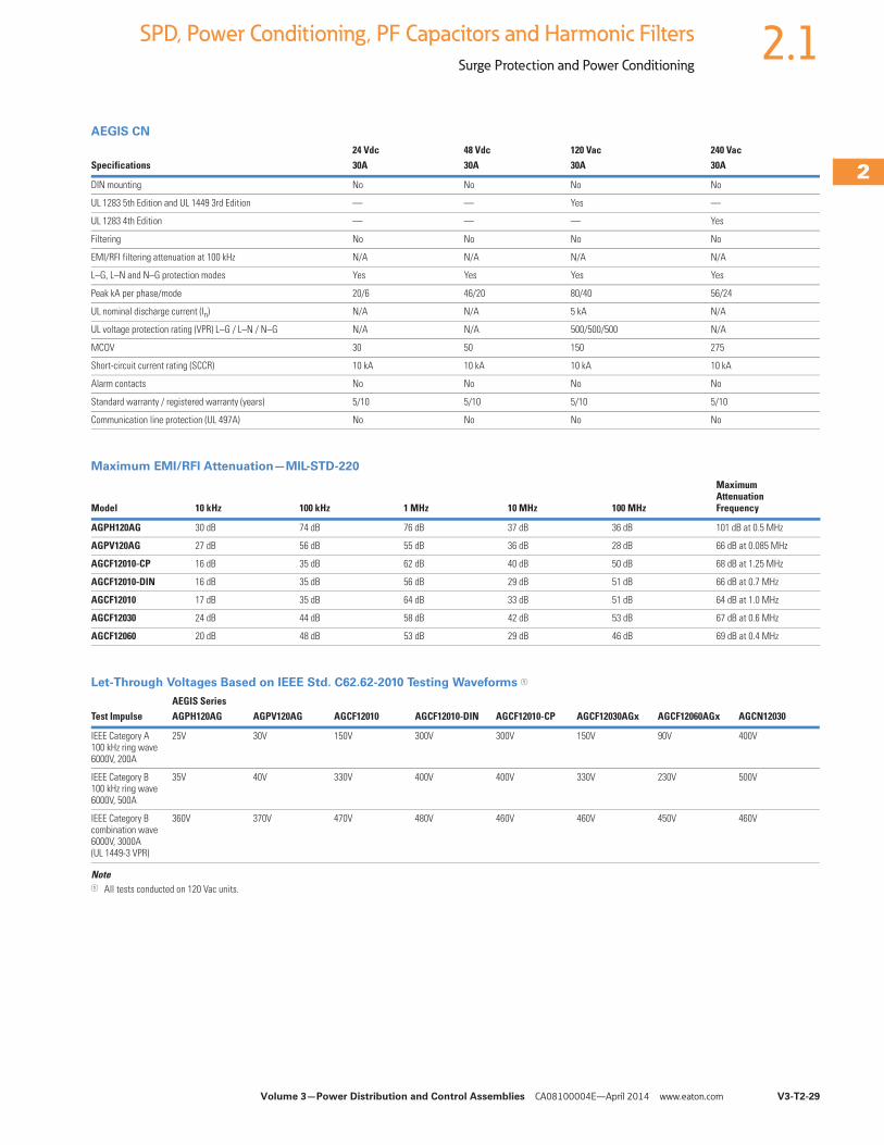
Volume 3—Power Distribution and Control Assemblies CA08100004E—April 2014 www.eaton.com V3-T2-29
2
2
2
2
2
2
2
2
2
2
2
2
2
2
2
2
2
2
2
2
2
2
2
2
2
2
2
2
2
2
2.1SPD, Power Conditioning, PF Capacitors and Harmonic Filters
Surge Protection and Power Conditioning
AEGIS CN
Maximum EMI/RFI Attenuation—MIL-STD-220
Let-Through Voltages Based on IEEE Std. C62.62-2010 Testing Waveforms 1
Note1 All tests conducted on 120 Vac units.
Specifications24 Vdc 48 Vdc 120 Vac 240 Vac30A 30A 30A 30A
DIN mounting No No No No
UL 1283 5th Edition and UL 1449 3rd Edition — — Yes —
UL 1283 4th Edition — — — Yes
Filtering No No No No
EMI/RFI filtering attenuation at 100 kHz N/A N/A N/A N/A
L–G, L–N and N–G protection modes Yes Yes Yes Yes
Peak kA per phase/mode 20/6 46/20 80/40 56/24
UL nominal discharge current (In) N/A N/A 5 kA N/A
UL voltage protection rating (VPR) L–G / L–N / N–G N/A N/A 500/500/500 N/A
MCOV 30 50 150 275
Short-circuit current rating (SCCR) 10 kA 10 kA 10 kA 10 kA
Alarm contacts No No No No
Standard warranty / registered warranty (years) 5/10 5/10 5/10 5/10
Communication line protection (UL 497A) No No No No
Model 10 kHz 100 kHz 1 MHz 10 MHz 100 MHz
MaximumAttenuationFrequency
AGPH120AG 30 dB 74 dB 76 dB 37 dB 36 dB 101 dB at 0.5 MHz
AGPV120AG 27 dB 56 dB 55 dB 36 dB 28 dB 66 dB at 0.085 MHz
AGCF12010-CP 16 dB 35 dB 62 dB 40 dB 50 dB 68 dB at 1.25 MHz
AGCF12010-DIN 16 dB 35 dB 56 dB 29 dB 51 dB 66 dB at 0.7 MHz
AGCF12010 17 dB 35 dB 64 dB 33 dB 51 dB 64 dB at 1.0 MHz
AGCF12030 24 dB 44 dB 58 dB 42 dB 53 dB 67 dB at 0.6 MHz
AGCF12060 20 dB 48 dB 53 dB 29 dB 46 dB 69 dB at 0.4 MHz
AEGIS SeriesTest Impulse AGPH120AG AGPV120AG AGCF12010 AGCF12010-DIN AGCF12010-CP AGCF12030AGx AGCF12060AGx AGCN12030
IEEE Category A 100 kHz ring wave6000V, 200A
25V 30V 150V 300V 300V 150V 90V 400V
IEEE Category B 100 kHz ring wave6000V, 500A
35V 40V 330V 400V 400V 330V 230V 500V
IEEE Category B combination wave6000V, 3000A (UL 1449-3 VPR)
360V 370V 470V 480V 460V 460V 450V 460V
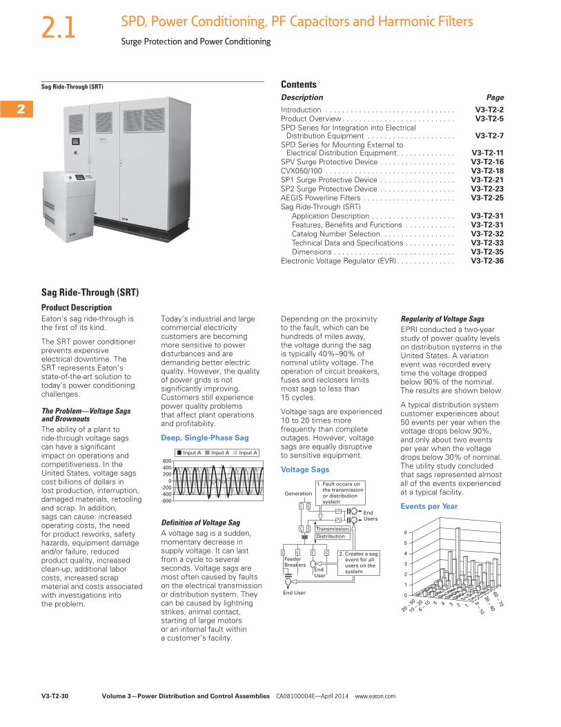
V3-T2-30 Volume 3—Power Distribution and Control Assemblies CA08100004E—April 2014 www.eaton.com
2
2
2
2
2
2
2
2
2
2
2
2
2
2
2
2
2
2
2
2
2
2
2
2
2
2
2
2
2
2
2.1 SPD, Power Conditioning, PF Capacitors and Harmonic Filters
Surge Protection and Power Conditioning
Sag Ride-Through (SRT) ContentsDescription Page
Introduction . . . . . . . . . . . . . . . . . . . . . . . . . . . . . . . V3-T2-2Product Overview . . . . . . . . . . . . . . . . . . . . . . . . . . . V3-T2-5
SPD Series for Integration into Electrical Distribution Equipment . . . . . . . . . . . . . . . . . . . . . V3-T2-7
SPD Series for Mounting External to Electrical Distribution Equipment. . . . . . . . . . . . . . V3-T2-11
SPV Surge Protective Device . . . . . . . . . . . . . . . . . . V3-T2-16CVX050/100 . . . . . . . . . . . . . . . . . . . . . . . . . . . . . . . V3-T2-18SP1 Surge Protective Device . . . . . . . . . . . . . . . . . . V3-T2-21
SP2 Surge Protective Device . . . . . . . . . . . . . . . . . . V3-T2-23AEGIS Powerline Filters . . . . . . . . . . . . . . . . . . . . . . V3-T2-25Sag Ride-Through (SRT)
Application Description . . . . . . . . . . . . . . . . . . . . V3-T2-31Features, Benefits and Functions . . . . . . . . . . . . V3-T2-31Catalog Number Selection. . . . . . . . . . . . . . . . . . V3-T2-32
Technical Data and Specifications . . . . . . . . . . . . V3-T2-33Dimensions . . . . . . . . . . . . . . . . . . . . . . . . . . . . . V3-T2-35
Electronic Voltage Regulator (EVR) . . . . . . . . . . . . . . V3-T2-36
Sag Ride-Through (SRT)Product DescriptionEaton’s sag ride-through is the first of its kind.
The SRT power conditioner prevents expensive electrical downtime. The SRT represents Eaton’s state-of-the-art solution to today’s power conditioning challenges.
The Problem—Voltage Sags and BrownoutsThe ability of a plant to ride-through voltage sags can have a significant impact on operations and competitiveness. In the United States, voltage sags cost billions of dollars in lost production, interruption, damaged materials, retooling and scrap. In addition, sags can cause: increased operating costs, the need for product reworks, safety hazards, equipment damage and/or failure, reduced product quality, increased clean-up, additional labor costs, increased scrap material and costs associated with investigations into the problem.
Today’s industrial and large commercial electricity customers are becoming more sensitive to power disturbances and are demanding better electric quality. However, the quality of power grids is not significantly improving. Customers still experience power quality problems that affect plant operations and profitability.
Deep, Single-Phase Sag
Definition of Voltage SagA voltage sag is a sudden, momentary decrease in supply voltage. It can last from a cycle to several seconds. Voltage sags are most often caused by faults on the electrical transmission or distribution system. They can be caused by lightning strikes, animal contact, starting of large motors or an internal fault within a customer’s facility.
Depending on the proximity to the fault, which can be hundreds of miles away, the voltage during the sag is typically 40%–90% of nominal utility voltage. The operation of circuit breakers, fuses and reclosers limits most sags to less than 15 cycles.
Voltage sags are experienced 10 to 20 times more frequently than complete outages. However, voltage sags are equally disruptive to sensitive equipment.
Voltage Sags
Regularity of Voltage SagsEPRI conducted a two-year study of power quality levels on distribution systems in the United States. A variation event was recorded every time the voltage dropped below 90% of the nominal. The results are shown below.
A typical distribution system customer experiences about 50 events per year when the voltage drops below 90%, and only about two events per year when the voltage drops below 30% of nominal. The utility study concluded that sags represented almost all of the events experienced at a typical facility.
Events per Year
600
400
200
0
-200
-400
-600
Input A Input A Input A
EndUsers
Transmission
Generation
Distribution
End User
End User
Feeder Breakers
1. Fault occurs on the transmission or distribution system
2. Creates a sag event for all users on the system
6
5
4
3
2
1
0
20 –
50
10 –
20
6 –
10 5 4 3 2 1
60 – 7
0
30 – 4
0
6 – 1
0
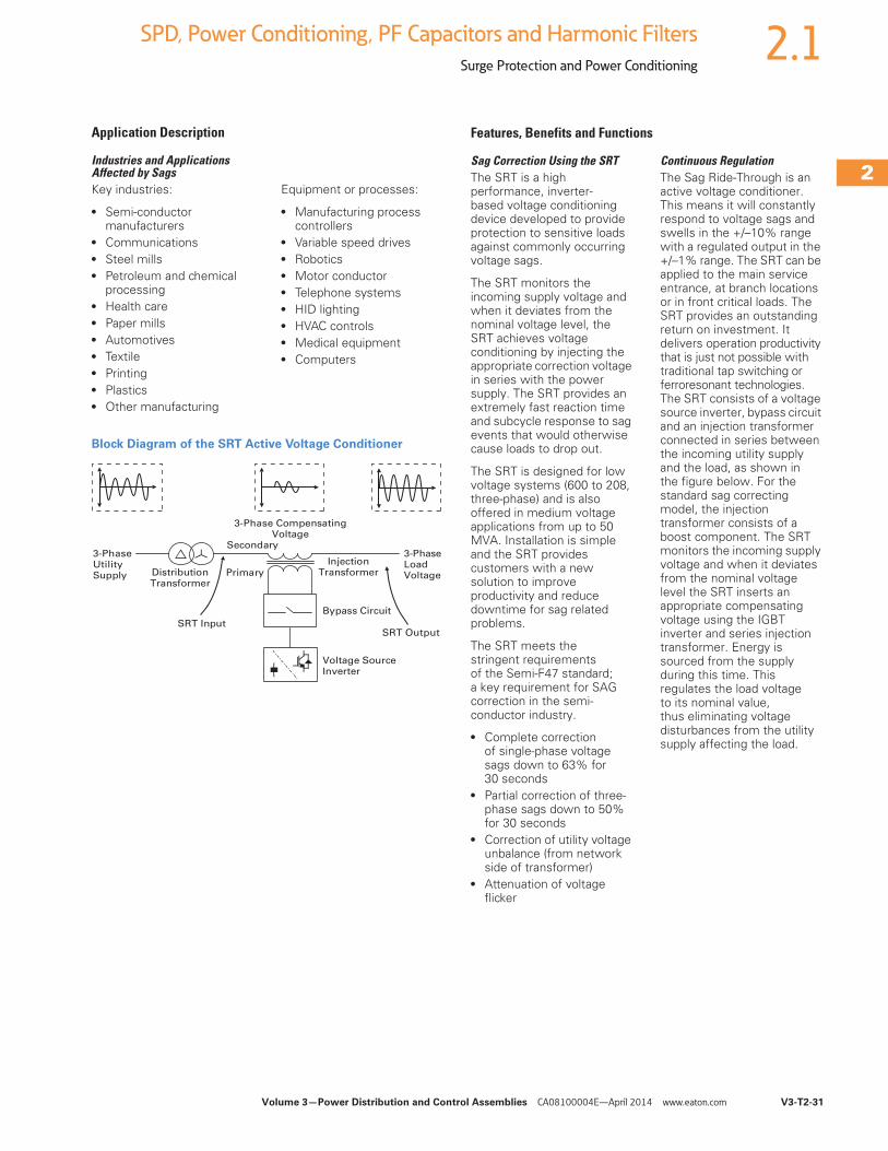
Volume 3—Power Distribution and Control Assemblies CA08100004E—April 2014 www.eaton.com V3-T2-31
2
2
2
2
2
2
2
2
2
2
2
2
2
2
2
2
2
2
2
2
2
2
2
2
2
2
2
2
2
2
2.1SPD, Power Conditioning, PF Capacitors and Harmonic Filters
Surge Protection and Power Conditioning
Application Description
Industries and Applications Affected by SagsKey industries:
● Semi-conductor manufacturers
● Communications● Steel mills● Petroleum and chemical
processing● Health care● Paper mills● Automotives● Textile● Printing● Plastics● Other manufacturing
Equipment or processes:
● Manufacturing process controllers
● Variable speed drives● Robotics● Motor conductor● Telephone systems● HID lighting● HVAC controls● Medical equipment● Computers
Block Diagram of the SRT Active Voltage Conditioner
3-PhaseUtilitySupply
3-Phase LoadVoltage
Voltage SourceInverter
InjectionTransformer
Bypass Circuit
Secondary
PrimaryDistributionTransformer
SRT Input
3-Phase CompensatingVoltage
SRT Output
Features, Benefits and Functions
Sag Correction Using the SRTThe SRT is a high performance, inverter-based voltage conditioning device developed to provide protection to sensitive loads against commonly occurring voltage sags.
The SRT monitors the incoming supply voltage and when it deviates from the nominal voltage level, the SRT achieves voltage conditioning by injecting the appropriate correction voltage in series with the power supply. The SRT provides an extremely fast reaction time and subcycle response to sag events that would otherwise cause loads to drop out.
The SRT is designed for low voltage systems (600 to 208, three-phase) and is also offered in medium voltage applications from up to 50 MVA. Installation is simple and the SRT provides customers with a new solution to improve productivity and reduce downtime for sag related problems.
The SRT meets the stringent requirements of the Semi-F47 standard; a key requirement for SAG correction in the semi-conductor industry.
● Complete correction of single-phase voltage sags down to 63% for 30 seconds
● Partial correction of three-phase sags down to 50% for 30 seconds
● Correction of utility voltage unbalance (from network side of transformer)
● Attenuation of voltage flicker
Continuous RegulationThe Sag Ride-Through is an active voltage conditioner. This means it will constantly respond to voltage sags and swells in the +/–10% range with a regulated output in the +/–1% range. The SRT can be applied to the main service entrance, at branch locations or in front critical loads. The SRT provides an outstanding return on investment. It delivers operation productivity that is just not possible with traditional tap switching or ferroresonant technologies. The SRT consists of a voltage source inverter, bypass circuit and an injection transformer connected in series between the incoming utility supply and the load, as shown in the figure below. For the standard sag correcting model, the injection transformer consists of a boost component. The SRT monitors the incoming supply voltage and when it deviates from the nominal voltage level the SRT inserts an appropriate compensating voltage using the IGBT inverter and series injection transformer. Energy is sourced from the supply during this time. This regulates the load voltage to its nominal value, thus eliminating voltage disturbances from the utility supply affecting the load.
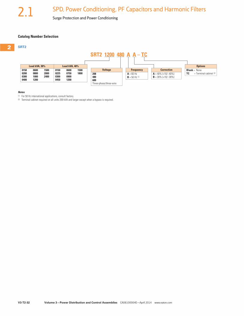
V3-T2-32 Volume 3—Power Distribution and Control Assemblies CA08100004E—April 2014 www.eaton.com
2
2
2
2
2
2
2
2
2
2
2
2
2
2
2
2
2
2
2
2
2
2
2
2
2
2
2
2
2
2
2.1 SPD, Power Conditioning, PF Capacitors and Harmonic Filters
Surge Protection and Power Conditioning
Catalog Number Selection
SRT2
Notes1 For 50 Hz international applications, consult factory.2 Terminal cabinet required on all units 200 kVA and larger except when a bypass is required.
FrequencyA = 60 HzB = 50 Hz 1
Load kVA, 30% Load kVA, 40%0150020003000400
0600080010001200
150020002400
0150022503000450
0600075009001200
15001800
OptionsBlank = NoneTC = Terminal cabinet 2
Voltage208480600Three-phase/three-wire
CorrectionA = 40% (+10/–40%)B = 30% (+10/–30%)
SRT2 1200 480 A A – TC
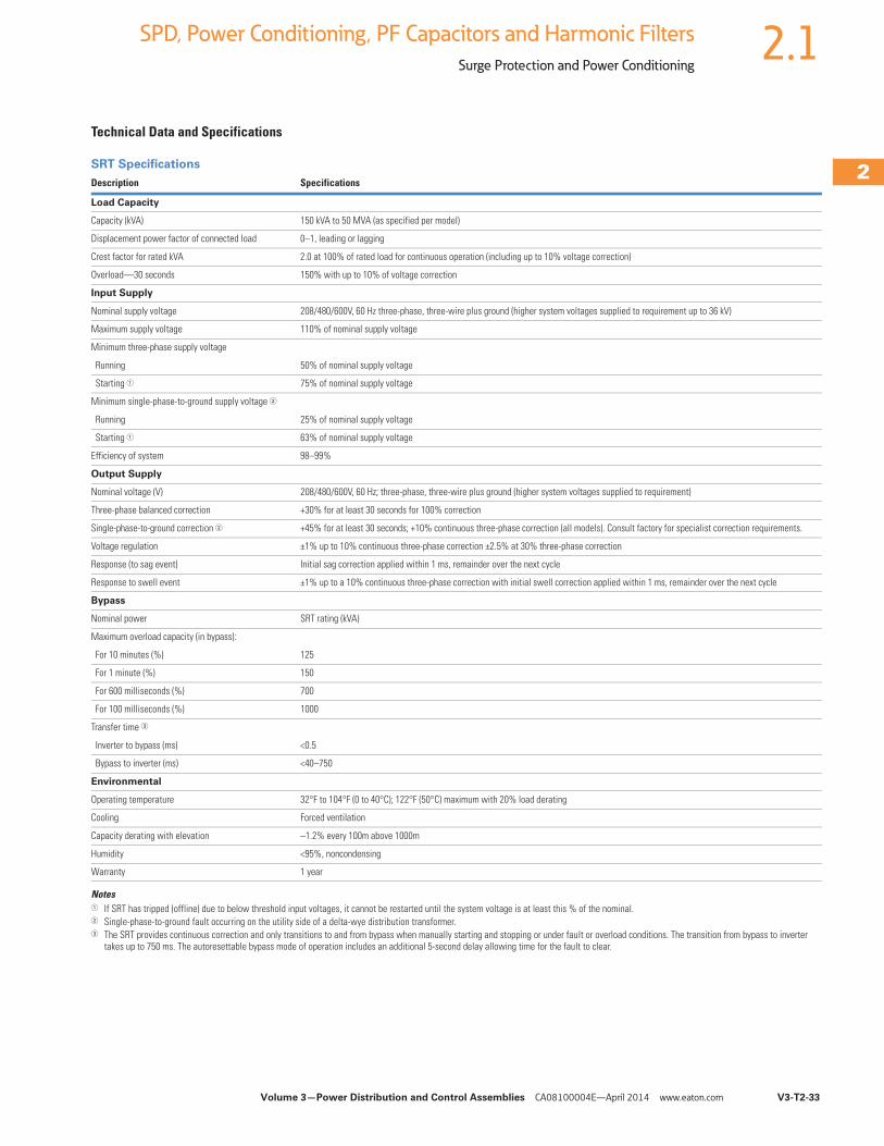
Volume 3—Power Distribution and Control Assemblies CA08100004E—April 2014 www.eaton.com V3-T2-33
2
2
2
2
2
2
2
2
2
2
2
2
2
2
2
2
2
2
2
2
2
2
2
2
2
2
2
2
2
2
2.1SPD, Power Conditioning, PF Capacitors and Harmonic Filters
Surge Protection and Power Conditioning
Technical Data and Specifications
SRT Specifications
Notes1 If SRT has tripped (offline) due to below threshold input voltages, it cannot be restarted until the system voltage is at least this % of the nominal.2 Single-phase-to-ground fault occurring on the utility side of a delta-wye distribution transformer.3 The SRT provides continuous correction and only transitions to and from bypass when manually starting and stopping or under fault or overload conditions. The transition from bypass to inverter
takes up to 750 ms. The autoresettable bypass mode of operation includes an additional 5-second delay allowing time for the fault to clear.
Description Specifications
Load Capacity
Capacity (kVA) 150 kVA to 50 MVA (as specified per model)
Displacement power factor of connected load 0–1, leading or lagging
Crest factor for rated kVA 2.0 at 100% of rated load for continuous operation (including up to 10% voltage correction)
Overload—30 seconds 150% with up to 10% of voltage correction
Input Supply
Nominal supply voltage 208/480/600V, 60 Hz three-phase, three-wire plus ground (higher system voltages supplied to requirement up to 36 kV)
Maximum supply voltage 110% of nominal supply voltage
Minimum three-phase supply voltage
Running 50% of nominal supply voltage
Starting 1 75% of nominal supply voltage
Minimum single-phase-to-ground supply voltage 2
Running 25% of nominal supply voltage
Starting 1 63% of nominal supply voltage
Efficiency of system 98–99%
Output Supply
Nominal voltage (V) 208/480/600V, 60 Hz; three-phase, three-wire plus ground (higher system voltages supplied to requirement)
Three-phase balanced correction +30% for at least 30 seconds for 100% correction
Single-phase-to-ground correction 2 +45% for at least 30 seconds; +10% continuous three-phase correction (all models). Consult factory for specialist correction requirements.
Voltage regulation ±1% up to 10% continuous three-phase correction ±2.5% at 30% three-phase correction
Response (to sag event) Initial sag correction applied within 1 ms, remainder over the next cycle
Response to swell event ±1% up to a 10% continuous three-phase correction with initial swell correction applied within 1 ms, remainder over the next cycle
Bypass
Nominal power SRT rating (kVA)
Maximum overload capacity (in bypass):
For 10 minutes (%) 125
For 1 minute (%) 150
For 600 milliseconds (%) 700
For 100 milliseconds (%) 1000
Transfer time 3
Inverter to bypass (ms) <0.5
Bypass to inverter (ms) <40–750
Environmental
Operating temperature 32°F to 104°F (0 to 40°C); 122°F (50°C) maximum with 20% load derating
Cooling Forced ventilation
Capacity derating with elevation –1.2% every 100m above 1000m
Humidity <95%, noncondensing
Warranty 1 year
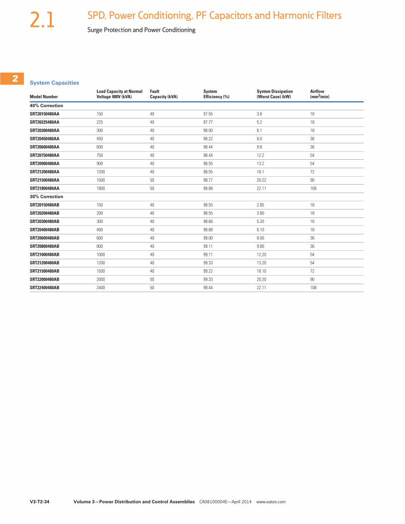
V3-T2-34 Volume 3—Power Distribution and Control Assemblies CA08100004E—April 2014 www.eaton.com
2
2
2
2
2
2
2
2
2
2
2
2
2
2
2
2
2
2
2
2
2
2
2
2
2
2
2
2
2
2
2.1 SPD, Power Conditioning, PF Capacitors and Harmonic Filters
Surge Protection and Power Conditioning
System Capacities
Model NumberLoad Capacity at Normal Voltage 480V (kVA)
Fault Capacity (kVA)
System Efficiency (%)
System Dissipation(Worst Case) (kW)
Airflow(mm3/min)
40% Correction
SRT20150480AA 150 40 97.55 3.8 18
SRT20225480AA 225 40 97.77 5.2 18
SRT20300480AA 300 40 98.00 6.1 18
SRT20450480AA 450 40 98.22 8.0 36
SRT20600480AA 600 40 98.44 9.8 36
SRT20750480AA 750 40 98.44 12.2 54
SRT20900480AA 900 40 98.55 13.2 54
SRT21200480AA 1200 40 98.55 18.1 72
SRT21500480AA 1500 50 98.77 20.22 90
SRT21800480AA 1800 50 98.88 22.11 108
30% Correction
SRT20150480AB 150 40 98.55 2.85 18
SRT20200480AB 200 40 98.55 3.80 18
SRT20300480AB 300 40 98.66 5.20 18
SRT20400480AB 400 40 98.88 6.10 18
SRT20600480AB 600 40 99.00 8.00 36
SRT20800480AB 800 40 99.11 9.80 36
SRT21000480AB 1000 40 99.11 12.20 54
SRT21200480AB 1200 40 99.33 13.20 54
SRT21500480AB 1500 40 99.22 18.10 72
SRT22000480AB 2000 50 99.33 20.20 90
SRT22400480AB 2400 50 99.44 22.11 108
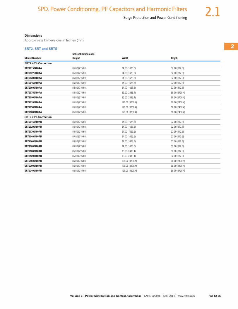
Volume 3—Power Distribution and Control Assemblies CA08100004E—April 2014 www.eaton.com V3-T2-35
2
2
2
2
2
2
2
2
2
2
2
2
2
2
2
2
2
2
2
2
2
2
2
2
2
2
2
2
2
2
2.1SPD, Power Conditioning, PF Capacitors and Harmonic Filters
Surge Protection and Power Conditioning
DimensionsApproximate Dimensions in Inches (mm)
SRT2, SRT and SRTS
Model NumberCabinet Dimensions Height Width Depth
SRT2 40% Correction
SRT20150480AA 85.00 (2159.0) 64.00 (1625.6) 32.00 (812.8)
SRT20225480AA 85.00 (2159.0) 64.00 (1625.6) 32.00 (812.8)
SRT20300480AA 85.00 (2159.0) 64.00 (1625.6) 32.00 (812.8)
SRT20450480AA 85.00 (2159.0) 64.00 (1625.6) 32.00 (812.8)
SRT20600480AA 85.00 (2159.0) 64.00 (1625.6) 32.00 (812.8)
SRT20750480AA 85.00 (2159.0) 96.00 (2438.4) 96.00 (2438.4)
SRT20900480AA 85.00 (2159.0) 96.00 (2438.4) 96.00 (2438.4)
SRT21200480AA 85.00 (2159.0) 126.00 (3200.4) 96.00 (2438.4)
SRT21500480AA 85.00 (2159.0) 126.00 (3200.4) 96.00 (2438.4)
SRT21800480AA 85.00 (2159.0) 126.00 (3200.4) 96.00 (2438.4)
SRT2 30% Correction
SRT20150480AB 85.00 (2159.0) 64.00 (1625.6) 32.00 (812.8)
SRT20200480AB 85.00 (2159.0) 64.00 (1625.6) 32.00 (812.8)
SRT20300480AB 85.00 (2159.0) 64.00 (1625.6) 32.00 (812.8)
SRT20400480AB 85.00 (2159.0) 64.00 (1625.6) 32.00 (812.8)
SRT20600480AB 85.00 (2159.0) 64.00 (1625.6) 32.00 (812.8)
SRT20800480AB 85.00 (2159.0) 64.00 (1625.6) 32.00 (812.8)
SRT21000480AB 85.00 (2159.0) 96.00 (2438.4) 32.00 (812.8)
SRT21200480AB 85.00 (2159.0) 96.00 (2438.4) 32.00 (812.8)
SRT21500480AB 85.00 (2159.0) 126.00 (3200.4) 96.00 (2438.4)
SRT22000480AB 85.00 (2159.0) 126.00 (3200.4) 96.00 (2438.4)
SRT22400480AB 85.00 (2159.0) 126.00 (3200.4) 96.00 (2438.4)
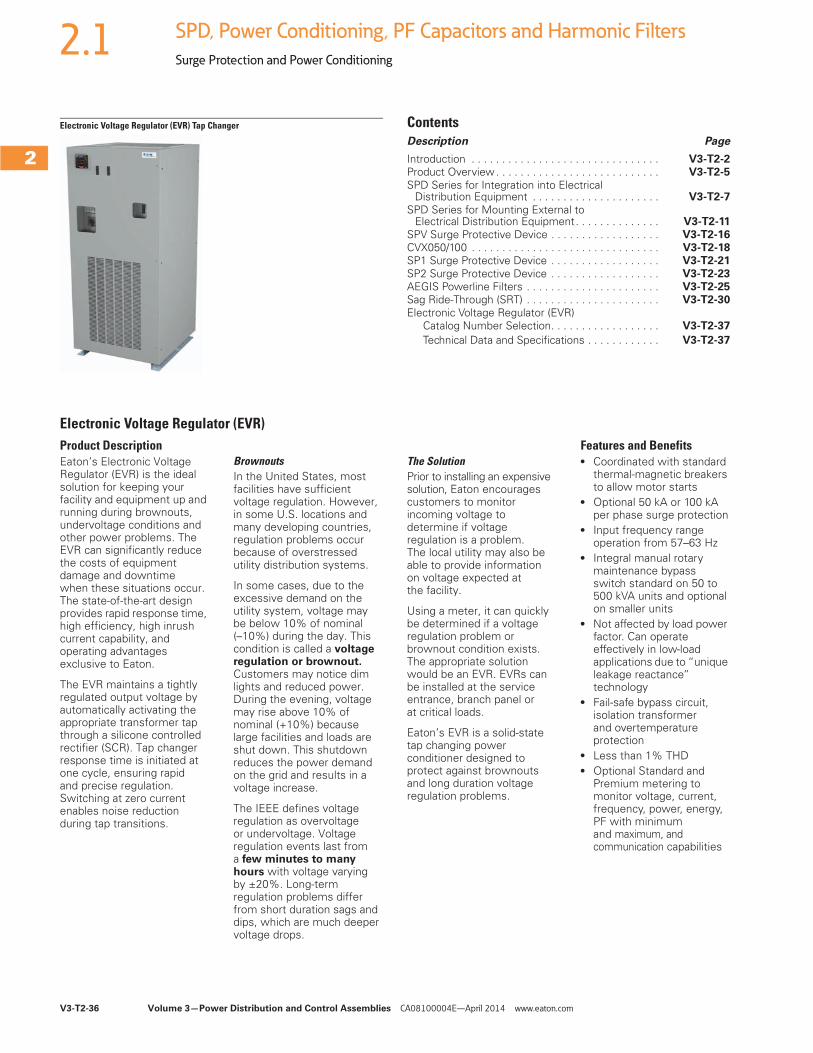
V3-T2-36 Volume 3—Power Distribution and Control Assemblies CA08100004E—April 2014 www.eaton.com
2
2
2
2
2
2
2
2
2
2
2
2
2
2
2
2
2
2
2
2
2
2
2
2
2
2
2
2
2
2
2.1 SPD, Power Conditioning, PF Capacitors and Harmonic Filters
Surge Protection and Power Conditioning
Electronic Voltage Regulator (EVR) Tap Changer ContentsDescription Page
Introduction . . . . . . . . . . . . . . . . . . . . . . . . . . . . . . . V3-T2-2Product Overview . . . . . . . . . . . . . . . . . . . . . . . . . . . V3-T2-5
SPD Series for Integration into Electrical Distribution Equipment . . . . . . . . . . . . . . . . . . . . . V3-T2-7
SPD Series for Mounting External to Electrical Distribution Equipment. . . . . . . . . . . . . . V3-T2-11
SPV Surge Protective Device . . . . . . . . . . . . . . . . . . V3-T2-16CVX050/100 . . . . . . . . . . . . . . . . . . . . . . . . . . . . . . . V3-T2-18SP1 Surge Protective Device . . . . . . . . . . . . . . . . . . V3-T2-21
SP2 Surge Protective Device . . . . . . . . . . . . . . . . . . V3-T2-23AEGIS Powerline Filters . . . . . . . . . . . . . . . . . . . . . . V3-T2-25Sag Ride-Through (SRT) . . . . . . . . . . . . . . . . . . . . . . V3-T2-30
Electronic Voltage Regulator (EVR)Catalog Number Selection. . . . . . . . . . . . . . . . . . V3-T2-37
Technical Data and Specifications . . . . . . . . . . . . V3-T2-37
Electronic Voltage Regulator (EVR)Product DescriptionEaton’s Electronic Voltage Regulator (EVR) is the ideal solution for keeping your facility and equipment up and running during brownouts, undervoltage conditions and other power problems. The EVR can significantly reduce the costs of equipment damage and downtime when these situations occur. The state-of-the-art design provides rapid response time, high efficiency, high inrush current capability, and operating advantages exclusive to Eaton.
The EVR maintains a tightly regulated output voltage by automatically activating the appropriate transformer tap through a silicone controlled rectifier (SCR). Tap changer response time is initiated at one cycle, ensuring rapid and precise regulation. Switching at zero current enables noise reduction during tap transitions.
BrownoutsIn the United States, most facilities have sufficient voltage regulation. However, in some U.S. locations and many developing countries, regulation problems occur because of overstressed utility distribution systems.
In some cases, due to the excessive demand on the utility system, voltage may be below 10% of nominal(–10%) during the day. This condition is called a voltage regulation or brownout. Customers may notice dim lights and reduced power. During the evening, voltage may rise above 10% of nominal (+10%) because large facilities and loads are shut down. This shutdown reduces the power demand on the grid and results in a voltage increase.
The IEEE defines voltage regulation as overvoltage or undervoltage. Voltage regulation events last from a few minutes to many hours with voltage varying by ±20%. Long-term regulation problems differ from short duration sags and dips, which are much deeper voltage drops.
The SolutionPrior to installing an expensive solution, Eaton encourages customers to monitor incoming voltage to determine if voltage regulation is a problem. The local utility may also be able to provide information on voltage expected at the facility.
Using a meter, it can quickly be determined if a voltage regulation problem or brownout condition exists. The appropriate solution would be an EVR. EVRs can be installed at the service entrance, branch panel or at critical loads.
Eaton’s EVR is a solid-state tap changing power conditioner designed to protect against brownouts and long duration voltage regulation problems.
Features and Benefits● Coordinated with standard
thermal-magnetic breakers to allow motor starts
● Optional 50 kA or 100 kA per phase surge protection
● Input frequency range operation from 57–63 Hz
● Integral manual rotary maintenance bypass switch standard on 50 to 500 kVA units and optional on smaller units
● Not affected by load power factor. Can operate effectively in low-load applications due to “unique leakage reactance” technology
● Fail-safe bypass circuit, isolation transformer and overtemperature protection
● Less than 1% THD● Optional Standard and
Premium metering to monitor voltage, current, frequency, power, energy, PF with minimum and maximum, and communication capabilities
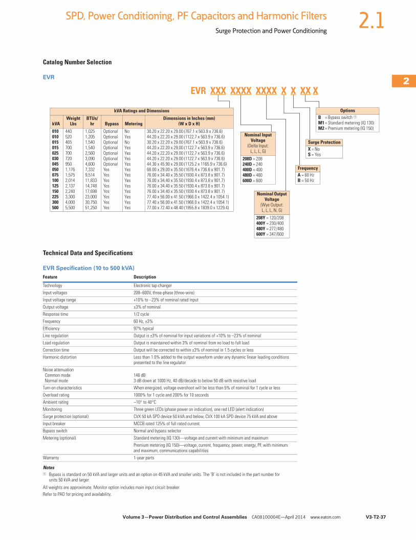
Volume 3—Power Distribution and Control Assemblies CA08100004E—April 2014 www.eaton.com V3-T2-37
2
2
2
2
2
2
2
2
2
2
2
2
2
2
2
2
2
2
2
2
2
2
2
2
2
2
2
2
2
2
2.1SPD, Power Conditioning, PF Capacitors and Harmonic Filters
Surge Protection and Power Conditioning
Catalog Number Selection
EVR
Technical Data and Specifications
EVR Specification (10 to 500 kVA)
Notes1 Bypass is standard on 50 kVA and larger units and an option on 45 kVA and smaller units. The ‘B’ is not included in the part number for
units 50 kVA and larger.
All weights are approximate. Monitor option includes main input circuit breaker.Refer to PAD for pricing and availability.
Feature Description
Technology Electronic tap changer
Input voltages 208–600V, three-phase (three-wire)
Input voltage range +10% to –23% of nominal rated input
Output voltage ±3% of nominal
Response time 1/2 cycle
Frequency 60 Hz, ±3%
Efficiency 97% typical
Line regulation Output is ±3% of nominal for input variations of +10% to –23% of nominal
Load regulation Output is maintained within 3% of nominal from no load to full load
Correction time Output will be corrected to within ±3% of nominal in 1.5 cycles or less
Harmonic distortion Less than 1.0% added to the output waveform under any dynamic linear loading conditions presented to the line regulator
Noise attenuation Common mode Normal mode
146 dB3 dB down at 1000 Hz, 40 dB/decade to below 50 dB with resistive load
Turn-on characteristics When energized, voltage overshoot will be less than 5% of nominal for 1 cycle or less
Overload rating 1000% for 1 cycle and 200% for 10 seconds
Ambient rating –10° to 40°C
Monitoring Three green LEDs (phase power on indication), one red LED (alert indication)
Surge protection (optional) CVX 50 kA SPD device 50 kVA and below, CVX 100 kA SPD device 75 kVA and above
Input breaker MCCB rated 125% of full rated current
Bypass switch Normal and bypass selector
Metering (optional) Standard metering (IQ 130)—voltage and current with minimum and maximum
Premium metering (IQ 150)—voltage, current, frequency, power, energy, PF, with minimum and maximum, communications capabilities
Warranty 1-year parts
Surge ProtectionX = NoS = Yes
FrequencyA = 60 HzB = 50 Hz
OptionsB = Bypass switch 1M1 = Standard metering (IQ 130)M2 = Premium metering (IQ 150)
Nominal Output Voltage
(Wye Output: L, L, L, N, G)
208Y = 120/208400Y = 230/400480Y = 277/480600Y = 347/600
kVA Ratings and Dimensions
kVAWeight
LbsBTUs/
hr Bypass MeteringDimensions in Inches (mm)
(W x D x H)
010010015015025030045050075100125150225300500
4405204657007007209501,1761,5752,0142,1372,2403,3004,0005,500
1,0251,2051,5401,5402,5603,0904,6007,3329,51411,83314,74817,69823,00030,75051,250
OptionalOptionalOptionalOptionalOptionalOptionalOptionalYesYesYesYesYesYesYesYes
NoYesNoYesYesYesYesYesYesYesYesYesYesYesYes
30.20 x 22.20 x 29.00 (767.1 x 563.9 x 736.6)44.20 x 22.20 x 29.00 (1122.7 x 563.9 x 736.6)30.20 x 22.20 x 29.00 (767.1 x 563.9 x 736.6)44.20 x 22.20 x 29.00 (1122.7 x 563.9 x 736.6)44.20 x 22.20 x 29.00 (1122.7 x 563.9 x 736.6)44.20 x 22.20 x 29.00 (1122.7 x 563.9 x 736.6)44.30 x 45.90 x 29.00 (1125.2 x 1165.9 x 736.6)66.00 x 29.00 x 35.50 (1676.4 x 736.6 x 901.7)76.00 x 34.40 x 35.50 (1930.4 x 873.8 x 901.7)76.00 x 34.40 x 35.50 (1930.4 x 873.8 x 901.7)76.00 x 34.40 x 35.50 (1930.4 x 873.8 x 901.7)76.00 x 34.40 x 35.50 (1930.4 x 873.8 x 901.7)77.40 x 56.00 x 41.50 (1966.0 x 1422.4 x 1054.1)77.40 x 56.00 x 41.50 (1966.0 x 1422.4 x 1054.1)77.00 x 72.40 x 48.40 (1955.8 x 1839.0 x 1229.4)
EVR XXX XXXX XXXX X X XX X
Nominal Input Voltage
(Delta Input: L, L, L, G)
208D = 208240D = 240400D = 400480D = 480600D = 600
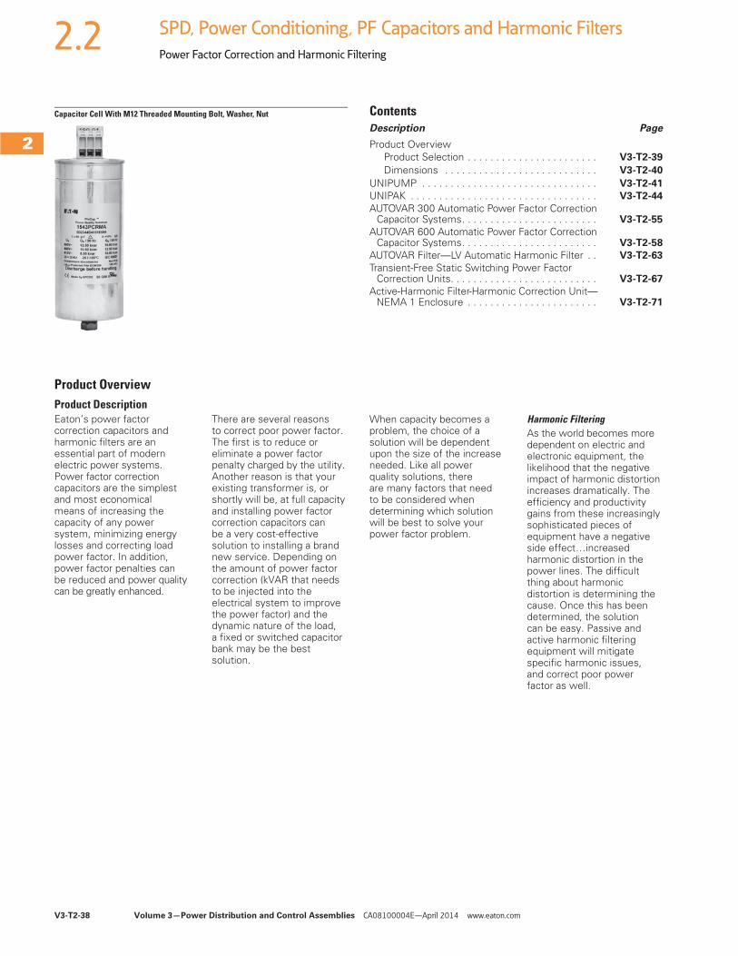
V3-T2-38 Volume 3—Power Distribution and Control Assemblies CA08100004E—April 2014 www.eaton.com
2
2
2
2
2
2
2
2
2
2
2
2
2
2
2
2
2
2
2
2
2
2
2
2
2
2
2
2
2
2
2.2 SPD, Power Conditioning, PF Capacitors and Harmonic Filters
Power Factor Correction and Harmonic Filtering
Capacitor Cell With M12 Threaded Mounting Bolt, Washer, Nut ContentsDescription Page
Product OverviewProduct Selection . . . . . . . . . . . . . . . . . . . . . . . V3-T2-39
Dimensions . . . . . . . . . . . . . . . . . . . . . . . . . . . V3-T2-40
UNIPUMP . . . . . . . . . . . . . . . . . . . . . . . . . . . . . . . V3-T2-41
UNIPAK . . . . . . . . . . . . . . . . . . . . . . . . . . . . . . . . . V3-T2-44
AUTOVAR 300 Automatic Power Factor CorrectionCapacitor Systems. . . . . . . . . . . . . . . . . . . . . . . . V3-T2-55
AUTOVAR 600 Automatic Power Factor CorrectionCapacitor Systems. . . . . . . . . . . . . . . . . . . . . . . . V3-T2-58
AUTOVAR Filter—LV Automatic Harmonic Filter . . V3-T2-63
Transient-Free Static Switching Power Factor Correction Units. . . . . . . . . . . . . . . . . . . . . . . . . . V3-T2-67
Active-Harmonic Filter-Harmonic Correction Unit—NEMA 1 Enclosure . . . . . . . . . . . . . . . . . . . . . . . V3-T2-71
Product OverviewProduct DescriptionEaton’s power factor correction capacitors and harmonic filters are an essential part of modern electric power systems. Power factor correction capacitors are the simplest and most economical means of increasing the capacity of any power system, minimizing energy losses and correcting load power factor. In addition, power factor penalties canbe reduced and power quality can be greatly enhanced.
There are several reasons to correct poor power factor. The first is to reduce or eliminate a power factor penalty charged by the utility. Another reason is that your existing transformer is, or shortly will be, at full capacity and installing power factor correction capacitors can be a very cost-effective solution to installing a brand new service. Depending on the amount of power factor correction (kVAR that needs to be injected into the electrical system to improve the power factor) and the dynamic nature of the load, a fixed or switched capacitor bank may be the best solution.
When capacity becomes a problem, the choice of a solution will be dependent upon the size of the increase needed. Like all power quality solutions, there are many factors that need to be considered when determining which solution will be best to solve your power factor problem.
Harmonic FilteringAs the world becomes more dependent on electric and electronic equipment, the likelihood that the negative impact of harmonic distortion increases dramatically. The efficiency and productivity gains from these increasingly sophisticated pieces of equipment have a negative side effect…increased harmonic distortion in the power lines. The difficult thing about harmonic distortion is determining the cause. Once this has been determined, the solution can be easy. Passive and active harmonic filtering equipment will mitigate specific harmonic issues, and correct poor power factor as well.
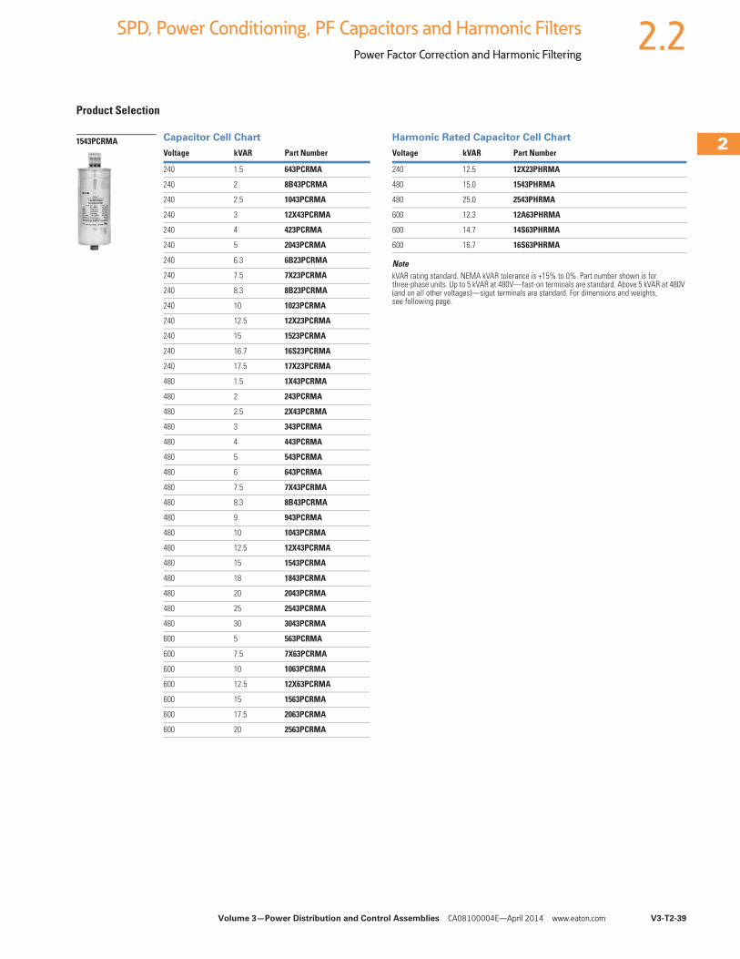
Volume 3—Power Distribution and Control Assemblies CA08100004E—April 2014 www.eaton.com V3-T2-39
2
2
2
2
2
2
2
2
2
2
2
2
2
2
2
2
2
2
2
2
2
2
2
2
2
2
2
2
2
2
2.2SPD, Power Conditioning, PF Capacitors and Harmonic Filters
Power Factor Correction and Harmonic Filtering
Product Selection
Capacitor Cell Chart Harmonic Rated Capacitor Cell Chart
NotekVAR rating standard. NEMA kVAR tolerance is +15% to 0%. Part number shown is for three-phase units. Up to 5 kVAR at 480V—fast-on terminals are standard. Above 5 kVAR at 480V (and on all other voltages)—sigut terminals are standard. For dimensions and weights, see following page.
Voltage kVAR Part Number
240 1.5 643PCRMA
240 2 8B43PCRMA
240 2.5 1043PCRMA
240 3 12X43PCRMA
240 4 423PCRMA
240 5 2043PCRMA
240 6.3 6B23PCRMA
240 7.5 7X23PCRMA
240 8.3 8B23PCRMA
240 10 1023PCRMA
240 12.5 12X23PCRMA
240 15 1523PCRMA
240 16.7 16S23PCRMA
240 17.5 17X23PCRMA
480 1.5 1X43PCRMA
480 2 243PCRMA
480 2.5 2X43PCRMA
480 3 343PCRMA
480 4 443PCRMA
480 5 543PCRMA
480 6 643PCRMA
480 7.5 7X43PCRMA
480 8.3 8B43PCRMA
480 9 943PCRMA
480 10 1043PCRMA
480 12.5 12X43PCRMA
480 15 1543PCRMA
480 18 1843PCRMA
480 20 2043PCRMA
480 25 2543PCRMA
480 30 3043PCRMA
600 5 563PCRMA
600 7.5 7X63PCRMA
600 10 1063PCRMA
600 12.5 12X63PCRMA
600 15 1563PCRMA
600 17.5 2063PCRMA
600 20 2563PCRMA
1543PCRMAVoltage kVAR Part Number
240 12.5 12X23PHRMA
480 15.0 1543PHRMA
480 25.0 2543PHRMA
600 12.3 12A63PHRMA
600 14.7 14S63PHRMA
600 16.7 16S63PHRMA
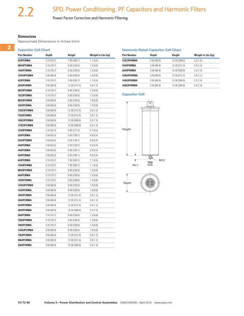
V3-T2-40 Volume 3—Power Distribution and Control Assemblies CA08100004E—April 2014 www.eaton.com
2
2
2
2
2
2
2
2
2
2
2
2
2
2
2
2
2
2
2
2
2
2
2
2
2
2
2
2
2
2
2.2 SPD, Power Conditioning, PF Capacitors and Harmonic Filters
Power Factor Correction and Harmonic Filtering
DimensionsApproximate Dimensions in Inches (mm)
Capacitor Cell Chart Harmonic Rated Capacitor Cell Chart
Capacitor Cell
Part Number Depth Height Weight in Lbs (kg)
643PCRMA 3.10 (78.7) 7.90 (200.7) 1.1 (0.5)
8B43PCRMA 3.10 (78.7) 9.40 (238.8) 1.3 (0.6)
1043PCRMA 3.10 (78.7) 9.40 (238.8) 1.3 (0.6)
12X43PCRMA 3.50 (88.9) 9.40 (238.8) 1.8 (0.8)
423PCRMA 3.10 (78.7) 7.90 (200.7) 1.1 (0.5)
2043PCRMA 3.50 (88.9) 12.30 (312.4) 2.6 (1.2)
6B23PCRMA 3.10 (78.7) 9.40 (238.8) 1.3 (0.6)
7X23PCRMA 3.10 (78.7) 9.40 (238.8) 1.3 (0.6)
8B23PCRMA 3.50 (88.9) 9.40 (238.8) 1.8 (0.8)
1023PCRMA 3.50 (88.9) 9.40 (238.8) 1.3 (0.6)
12X23PCRMA 3.50 (88.9) 12.30 (312.4) 2.6 (1.2)
1523PCRMA 3.50 (88.9) 12.30 (312.4) 2.6 (1.2)
16S23PCRMA 3.50 (88.9) 15.30 (388.6) 3.3 (1.5)
17X23PCRMA 3.50 (88.9) 15.30 (388.6) 3.3 (1.5)
1X43PCRMA 2.10 (53.3) 5.00 (127.0) 0.7 (0.3)
243PCRMA 2.50 (63.5) 5.50 (139.7) 0.9 (0.4)
2X43PCRMA 2.50 (63.5) 5.50 (139.7) 0.9 (0.4)
343PCRMA 2.50 (63.5) 5.50 (139.7) 0.9 (0.4)
443PCRMA 2.50 (63.5) 6.50 (165.1) 0.9 (0.4)
543PCRMA 2.50 (63.5) 6.50 (165.1) 0.9 (0.4)
643PCRMA 3.10 (78.7) 7.90 (200.7) 1.1 (0.5)
7X43PCRMA 3.10 (78.7) 7.90 (200.7) 1.1 (0.5)
8B43PCRMA 3.10 (78.7) 9.40 (238.8) 1.3 (0.6)
943PCRMA 3.10 (78.7) 9.40 (238.8) 1.3 (0.6)
1043PCRMA 3.10 (78.7) 9.40 (238.8) 1.3 (0.6)
12X43PCRMA 3.50 (88.9) 9.40 (238.8) 1.8 (0.8)
1543PCRMA 3.50 (88.9) 9.40 (238.8) 1.8 (0.8)
1843PCRMA 3.50 (88.9) 12.30 (312.4) 2.6 (1.2)
2043PCRMA 3.50 (88.9) 12.30 (312.4) 2.6 (1.2)
2543PCRMA 3.50 (88.9) 12.30 (312.4) 2.6 (1.2)
3043PCRMA 3.50 (88.9) 15.30 (388.6) 3.3 (1.5)
563PCRMA 3.10 (78.7) 9.40 (238.8) 1.3 (0.6)
7X63PCRMA 3.10 (78.7) 9.40 (238.8) 1.3 (0.6)
1063PCRMA 3.10 (78.7) 9.40 (238.8) 1.3 (0.6)
12X63PCRMA 3.50 (88.9) 9.40 (238.8) 1.8 (0.8)
1563PCRMA 3.50 (88.9) 12.30 (312.4) 2.6 (1.2)
2063PCRMA 3.50 (88.9) 12.30 (312.4) 2.6 (1.2)
2563PCRMA 3.50 (88.9) 15.30 (388.6) 3.3 (1.5)
Part Number Depth Height Weight in Lbs (kg)
12X23PHRMA 3.50 (88.9) 15.30 (388.6) 3.3 (1.5)
1543PHRMA 3.50 (88.9) 12.30 (312.4) 2.6 (1.2)
2543PHRMA 3.50 (88.9) 15.30 (388.6) 3.3 (1.5)
12A63PHRMA 3.50 (88.9) 12.30 (312.4) 2.6 (1.2)
14S63PHRMA 3.50 (88.9) 15.30 (388.6) 3.3 (1.5)
16S63PHRMA 3.50 (88.9) 15.30 (388.6) 3.3 (1.5)
Height
M12
16+1
Depth
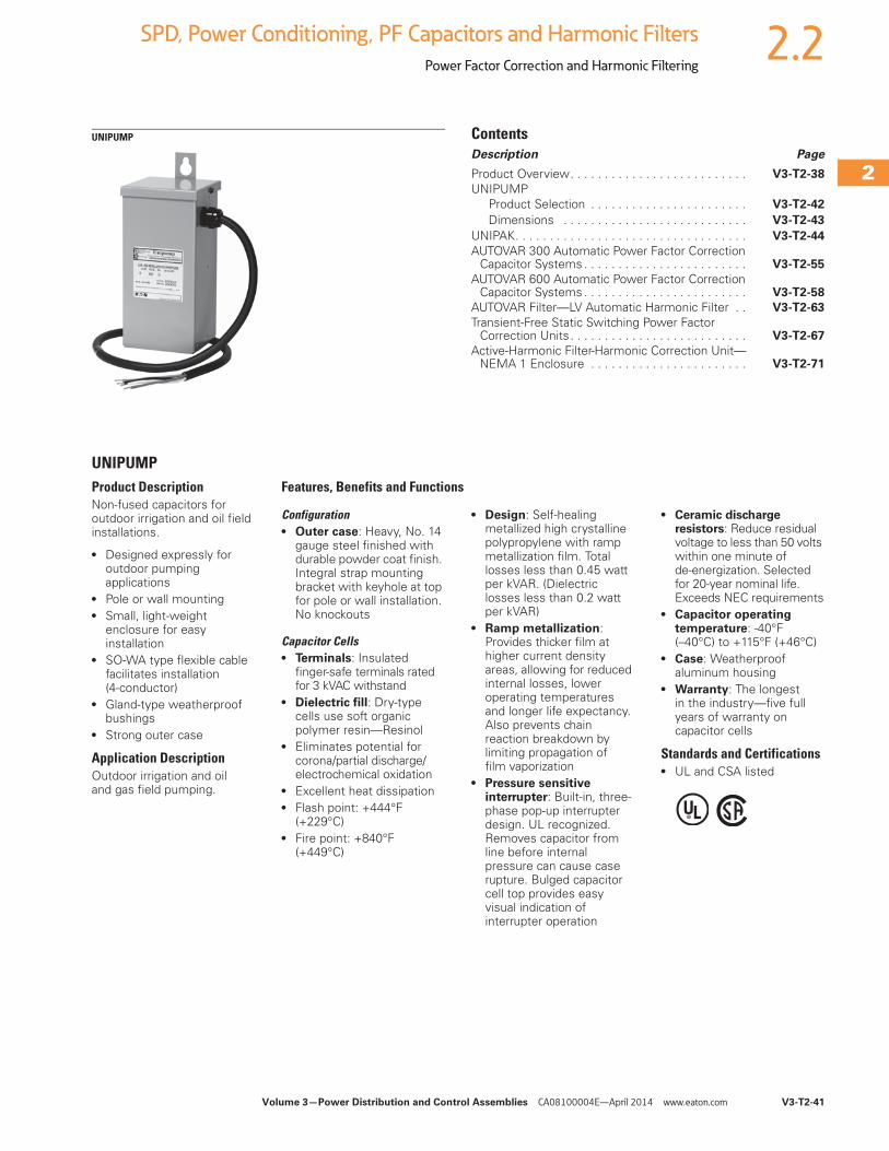
Volume 3—Power Distribution and Control Assemblies CA08100004E—April 2014 www.eaton.com V3-T2-41
2
2
2
2
2
2
2
2
2
2
2
2
2
2
2
2
2
2
2
2
2
2
2
2
2
2
2
2
2
2
2.2SPD, Power Conditioning, PF Capacitors and Harmonic Filters
Power Factor Correction and Harmonic Filtering
UNIPUMP ContentsDescription Page
Product Overview. . . . . . . . . . . . . . . . . . . . . . . . . . V3-T2-38
UNIPUMPProduct Selection . . . . . . . . . . . . . . . . . . . . . . . V3-T2-42
Dimensions . . . . . . . . . . . . . . . . . . . . . . . . . . . V3-T2-43
UNIPAK. . . . . . . . . . . . . . . . . . . . . . . . . . . . . . . . . . V3-T2-44
AUTOVAR 300 Automatic Power Factor Correction Capacitor Systems . . . . . . . . . . . . . . . . . . . . . . . . V3-T2-55
AUTOVAR 600 Automatic Power Factor Correction Capacitor Systems . . . . . . . . . . . . . . . . . . . . . . . . V3-T2-58
AUTOVAR Filter—LV Automatic Harmonic Filter . . V3-T2-63
Transient-Free Static Switching Power Factor Correction Units . . . . . . . . . . . . . . . . . . . . . . . . . . V3-T2-67
Active-Harmonic Filter-Harmonic Correction Unit—NEMA 1 Enclosure . . . . . . . . . . . . . . . . . . . . . . . V3-T2-71
UNIPUMPProduct DescriptionNon-fused capacitors for outdoor irrigation and oil field installations.
● Designed expressly for outdoor pumping applications
● Pole or wall mounting● Small, light-weight
enclosure for easy installation
● SO-WA type flexible cable facilitates installation (4-conductor)
● Gland-type weatherproof bushings
● Strong outer case
Application DescriptionOutdoor irrigation and oil and gas field pumping.
Features, Benefits and Functions
Configuration● Outer case: Heavy, No. 14
gauge steel finished with durable powder coat finish. Integral strap mounting bracket with keyhole at top for pole or wall installation. No knockouts
Capacitor Cells● Terminals: Insulated
finger-safe terminals rated for 3 kVAC withstand
● Dielectric fill: Dry-type cells use soft organic polymer resin—Resinol
● Eliminates potential for corona/partial discharge/electrochemical oxidation
● Excellent heat dissipation● Flash point: +444°F
(+229°C)● Fire point: +840°F
(+449°C)
● Design: Self-healing metallized high crystalline polypropylene with ramp metallization film. Total losses less than 0.45 watt per kVAR. (Dielectric losses less than 0.2 watt per kVAR)
● Ramp metallization: Provides thicker film at higher current density areas, allowing for reduced internal losses, lower operating temperatures and longer life expectancy. Also prevents chain reaction breakdown by limiting propagation of film vaporization
● Pressure sensitive interrupter: Built-in, three-phase pop-up interrupter design. UL recognized. Removes capacitor from line before internal pressure can cause case rupture. Bulged capacitor cell top provides easy visual indication of interrupter operation
● Ceramic discharge resistors: Reduce residual voltage to less than 50 volts within one minute of de-energization. Selected for 20-year nominal life. Exceeds NEC requirements
● Capacitor operating temperature: -40°F(–40°C) to +115°F (+46°C)
● Case: Weatherproof aluminum housing
● Warranty: The longest in the industry—five full years of warranty on capacitor cells
Standards and Certifications● UL and CSA listed
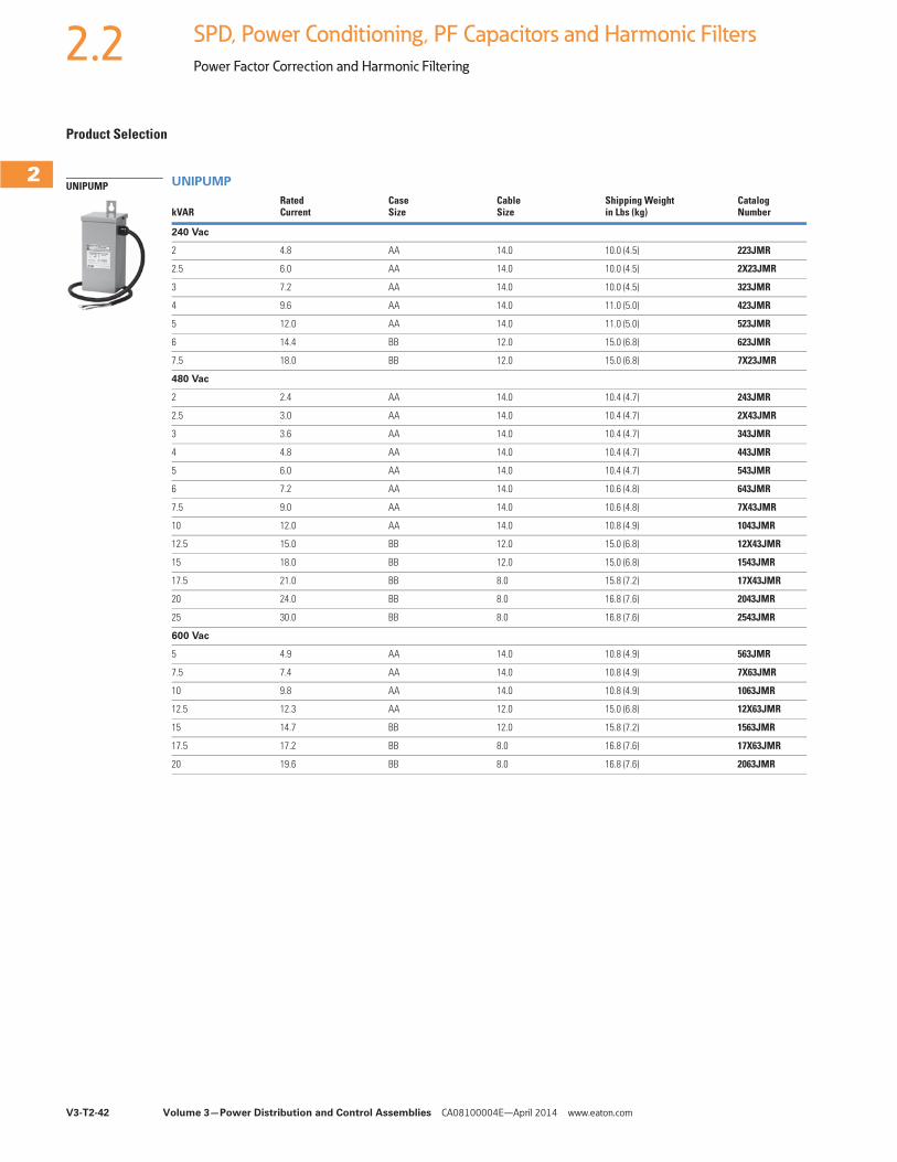
V3-T2-42 Volume 3—Power Distribution and Control Assemblies CA08100004E—April 2014 www.eaton.com
2
2
2
2
2
2
2
2
2
2
2
2
2
2
2
2
2
2
2
2
2
2
2
2
2
2
2
2
2
2
2.2 SPD, Power Conditioning, PF Capacitors and Harmonic Filters
Power Factor Correction and Harmonic Filtering
Product Selection
UNIPUMP
kVARRated Current
Case Size
Cable Size
Shipping Weight in Lbs (kg)
Catalog Number
240 Vac
2 4.8 AA 14.0 10.0 (4.5) 223JMR
2.5 6.0 AA 14.0 10.0 (4.5) 2X23JMR
3 7.2 AA 14.0 10.0 (4.5) 323JMR
4 9.6 AA 14.0 11.0 (5.0) 423JMR
5 12.0 AA 14.0 11.0 (5.0) 523JMR
6 14.4 BB 12.0 15.0 (6.8) 623JMR
7.5 18.0 BB 12.0 15.0 (6.8) 7X23JMR
480 Vac
2 2.4 AA 14.0 10.4 (4.7) 243JMR
2.5 3.0 AA 14.0 10.4 (4.7) 2X43JMR
3 3.6 AA 14.0 10.4 (4.7) 343JMR
4 4.8 AA 14.0 10.4 (4.7) 443JMR
5 6.0 AA 14.0 10.4 (4.7) 543JMR
6 7.2 AA 14.0 10.6 (4.8) 643JMR
7.5 9.0 AA 14.0 10.6 (4.8) 7X43JMR
10 12.0 AA 14.0 10.8 (4.9) 1043JMR
12.5 15.0 BB 12.0 15.0 (6.8) 12X43JMR
15 18.0 BB 12.0 15.0 (6.8) 1543JMR
17.5 21.0 BB 8.0 15.8 (7.2) 17X43JMR
20 24.0 BB 8.0 16.8 (7.6) 2043JMR
25 30.0 BB 8.0 16.8 (7.6) 2543JMR
600 Vac
5 4.9 AA 14.0 10.8 (4.9) 563JMR
7.5 7.4 AA 14.0 10.8 (4.9) 7X63JMR
10 9.8 AA 14.0 10.8 (4.9) 1063JMR
12.5 12.3 AA 12.0 15.0 (6.8) 12X63JMR
15 14.7 BB 12.0 15.8 (7.2) 1563JMR
17.5 17.2 BB 8.0 16.8 (7.6) 17X63JMR
20 19.6 BB 8.0 16.8 (7.6) 2063JMR
UNIPUMP
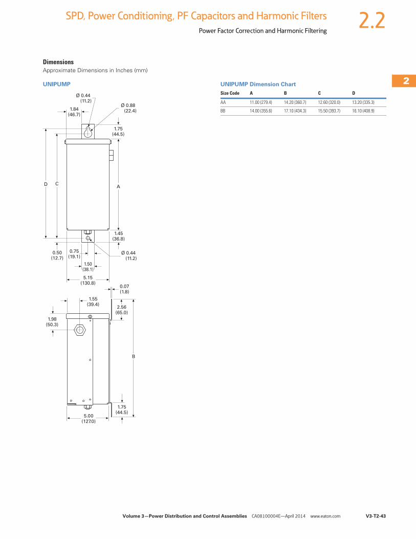
Volume 3—Power Distribution and Control Assemblies CA08100004E—April 2014 www.eaton.com V3-T2-43
2
2
2
2
2
2
2
2
2
2
2
2
2
2
2
2
2
2
2
2
2
2
2
2
2
2
2
2
2
2
2.2SPD, Power Conditioning, PF Capacitors and Harmonic Filters
Power Factor Correction and Harmonic Filtering
DimensionsApproximate Dimensions in Inches (mm)
UNIPUMP UNIPUMP Dimension Chart
Ø 0.44 (11.2)
1.84(46.7)
D C
Ø 0.88 (22.4)
1.75(44.5)
A
Ø 0.44 (11.2)
1.45(36.8)
5.00(127.0)
1.50(38.1)
5.15(130.8)
0.75(19.1)
0.50(12.7)
0.07(1.8)
1.55(39.4)
1.98(50.3)
2.56(65.0)
B
1.75(44.5)
Size Code A B C D
AA 11.00 (279.4) 14.20 (360.7) 12.60 (320.0) 13.20 (335.3)
BB 14.00 (355.6) 17.10 (434.3) 15.50 (393.7) 16.10 (408.9)
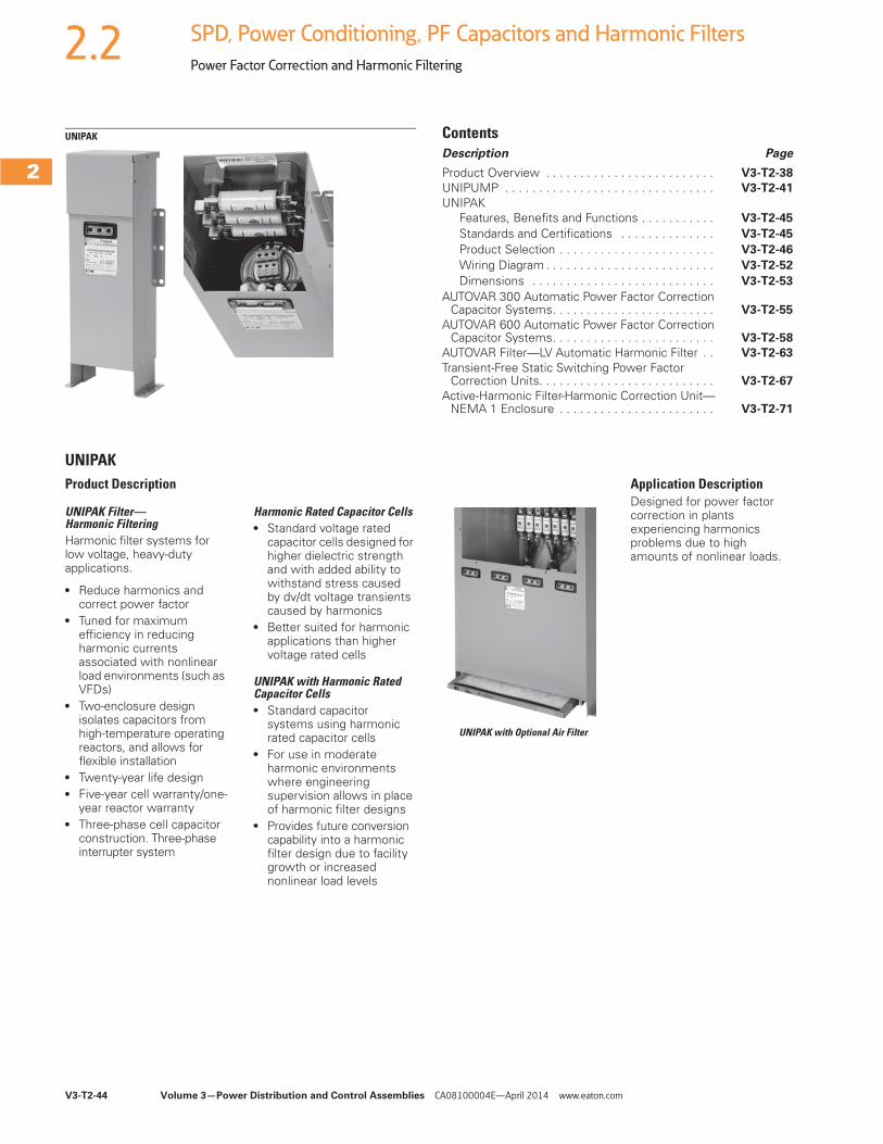
V3-T2-44 Volume 3—Power Distribution and Control Assemblies CA08100004E—April 2014 www.eaton.com
2
2
2
2
2
2
2
2
2
2
2
2
2
2
2
2
2
2
2
2
2
2
2
2
2
2
2
2
2
2
2.2 SPD, Power Conditioning, PF Capacitors and Harmonic Filters
Power Factor Correction and Harmonic Filtering
UNIPAK ContentsDescription Page
Product Overview . . . . . . . . . . . . . . . . . . . . . . . . . V3-T2-38
UNIPUMP . . . . . . . . . . . . . . . . . . . . . . . . . . . . . . . V3-T2-41
UNIPAKFeatures, Benefits and Functions . . . . . . . . . . . V3-T2-45
Standards and Certifications . . . . . . . . . . . . . . V3-T2-45
Product Selection . . . . . . . . . . . . . . . . . . . . . . . V3-T2-46
Wiring Diagram . . . . . . . . . . . . . . . . . . . . . . . . . V3-T2-52
Dimensions . . . . . . . . . . . . . . . . . . . . . . . . . . . V3-T2-53
AUTOVAR 300 Automatic Power Factor Correction Capacitor Systems. . . . . . . . . . . . . . . . . . . . . . . . V3-T2-55
AUTOVAR 600 Automatic Power Factor Correction Capacitor Systems. . . . . . . . . . . . . . . . . . . . . . . . V3-T2-58
AUTOVAR Filter—LV Automatic Harmonic Filter . . V3-T2-63
Transient-Free Static Switching Power Factor Correction Units. . . . . . . . . . . . . . . . . . . . . . . . . . V3-T2-67
Active-Harmonic Filter-Harmonic Correction Unit—NEMA 1 Enclosure . . . . . . . . . . . . . . . . . . . . . . . V3-T2-71
UNIPAKProduct Description
UNIPAK Filter— Harmonic FilteringHarmonic filter systems for low voltage, heavy-duty applications.
● Reduce harmonics and correct power factor
● Tuned for maximum efficiency in reducing harmonic currents associated with nonlinear load environments (such as VFDs)
● Two-enclosure design isolates capacitors from high-temperature operating reactors, and allows for flexible installation
● Twenty-year life design● Five-year cell warranty/one-
year reactor warranty● Three-phase cell capacitor
construction. Three-phase interrupter system
Harmonic Rated Capacitor Cells● Standard voltage rated
capacitor cells designed for higher dielectric strength and with added ability to withstand stress caused by dv/dt voltage transients caused by harmonics
● Better suited for harmonic applications than higher voltage rated cells
UNIPAK with Harmonic Rated Capacitor Cells● Standard capacitor
systems using harmonic rated capacitor cells
● For use in moderate harmonic environments where engineering supervision allows in place of harmonic filter designs
● Provides future conversion capability into a harmonic filter design due to facility growth or increased nonlinear load levels
UNIPAK with Optional Air Filter
Application DescriptionDesigned for power factor correction in plants experiencing harmonics problems due to high amounts of nonlinear loads.
Volume 3—Power Distribution and Control Assemblies CA08100004E—April 2014 www.eaton.com V3-T2-45
2
2
2
2
2
2
2
2
2
2
2
2
2
2
2
2
2
2
2
2
2
2
2
2
2
2
2
2
2
2
2.2SPD, Power Conditioning, PF Capacitors and Harmonic Filters
Power Factor Correction and Harmonic Filtering
Features, Benefits and Functions● Five-year warranty
on capacitor cells● Designed for heavy-duty
applications● Twenty-year life design● Indoor/outdoor service● Wall (up to 180 kVAR)
and floor-mounted units available
● Fuse protection standard● Blown-fuse indicating
lights standard● Quick lead-times● Harmonic filters available● Slim profile allows reduced
footprint, conserving valuable floor space● New capacitor
configuration leads to cooler operating conditions, extending capacitor life
Configuration● Outer case: Heavy, No. 14
gauge steel finished with durable powder coat finish. Wall mounting flanges and floor mounting feet. Elimination of knockouts permits indoor/outdoor use. Manufactured to NEMA requirements 1, 3R and 12
● Elevated floor mounting feet allow access for easy maintenance
Note: NEMA 12 enclosure standard for enclosure sizes A1 to C1.
● Cover: “L” shaped gasketed cover with multiple fasteners provides front opening for ease of installation and service
● Ground terminal: Furnished inside case
● Power terminal lugs: Large size provided for easy connection
● Fusing:● Size Code A1: Three
midget-type fuses with 100,000 ampere interrupting capacity
● Size Code A2 and larger: Three slotted-blade type fuses with 200,000 ampere interrupting capacity; Fuses mounted on stand-off bushings or fuse blocks; solderless connectors for easy hookup of incoming line conductors
● Fuse indicating lights: Red, neon blown-fuse indicating lights are protected by transparent weatherproof guard
● Options:● No fuses● Air filters for units
with enclosure sizes C2, D1 and E1
Capacitor cells● Terminals: Insulated finger-
safe terminals rated for 3 kVAC withstand
● Dielectric fill: Dry-type cells use soft organic polymer resin—Resinol● Eliminates potential for
corona/partial discharge/electrochemical oxidation
● Excellent heat dissipation
● Flash point: +444°F (+229°C)
● Fire point: +840°F (+449°C)
● Design: Self-healing metallized high crystalline polypropylene with ramp metallization film. Total losses less than 0.45 watt per kVAR. (Dielectric losses less than 0.2 watt per kVAR)
● Ramp metallization: Provides thicker film at higher current density areas, allowing for reduced internal losses, lower operating temperatures and longer life expectancy. Also prevents chain reaction breakdown by limiting propagation of film vaporization
● Pressure sensitive interrupter: Built-in, three-phase pop-up interrupter design. UL recognized. Removes capacitor from line before internal pressure can cause case rupture. Bulged capacitor cell top provides easy visual indication of interrupter operation
● Ceramic discharge resistors: Reduce residual voltage to less than 50 volts within one minute of de-energization. Selected for 20-year nominal life. Exceeds NEC requirements
● Capacitor operating temperature: -40°F (-40°C) to +115°F (+46°C)
● Case: Weatherproof aluminum housing
● Warranty: The longest in the industry—five full years of warranty on capacitor cells
Reactors● Tuning: Tuned to 4.7
harmonic order● Detuning: Reactor
designs can be detuned upon request to 4.2nd to protect capacitors against alternate harmonics
● Construction: 100% copper windings for cool operating temperatures; designed operating temperature rise less than 80ºC. Open frame construction with 220ºC insulation system
● Thermal sensors: One per phase, self-resetting thermistors provide reactor over-temperature protection and indication
● Reactor indicating light: Thermal overload indicating light activates when reactor temperature reaches 180ºC
● Warranty: One-year replacement of reactors
Standards and Certifications● UL and CSA listed
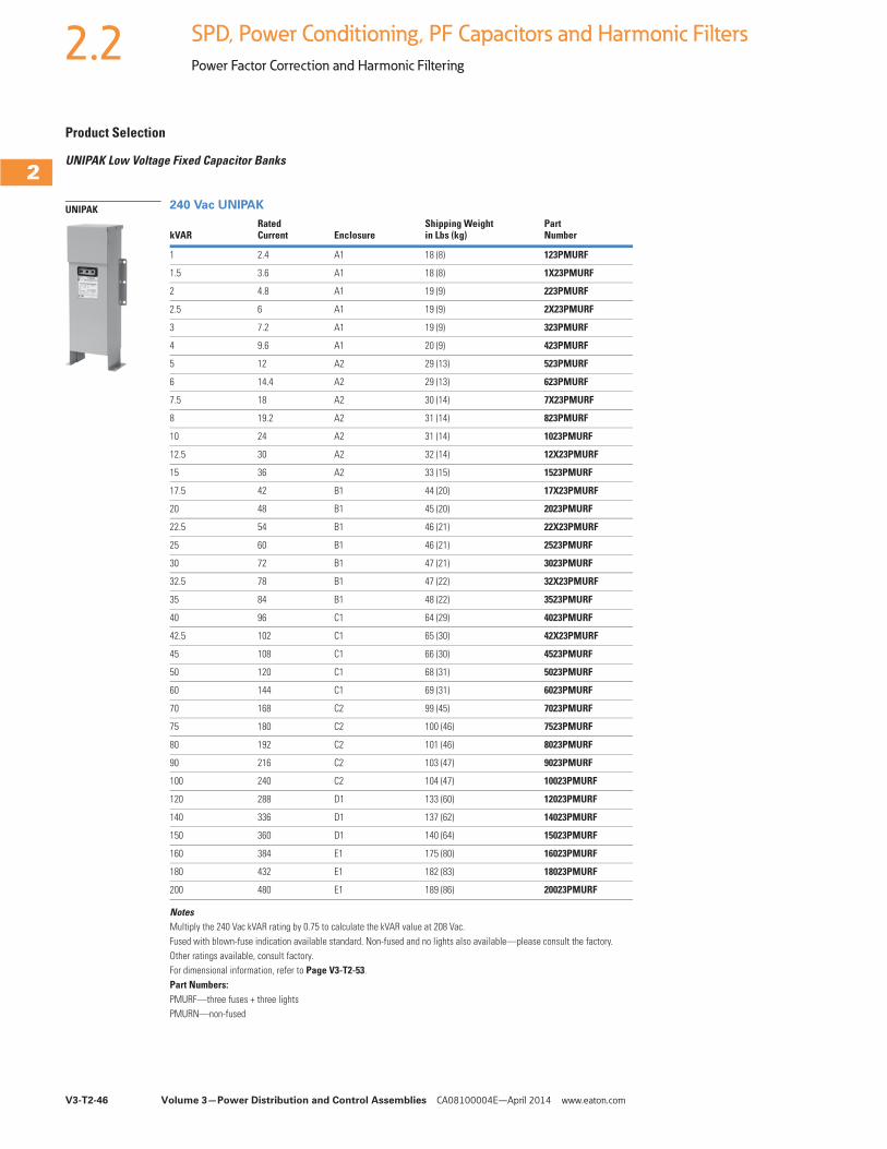
V3-T2-46 Volume 3—Power Distribution and Control Assemblies CA08100004E—April 2014 www.eaton.com
2
2
2
2
2
2
2
2
2
2
2
2
2
2
2
2
2
2
2
2
2
2
2
2
2
2
2
2
2
2
2.2 SPD, Power Conditioning, PF Capacitors and Harmonic Filters
Power Factor Correction and Harmonic Filtering
Product Selection
UNIPAK Low Voltage Fixed Capacitor Banks
240 Vac UNIPAK
NotesMultiply the 240 Vac kVAR rating by 0.75 to calculate the kVAR value at 208 Vac.Fused with blown-fuse indication available standard. Non-fused and no lights also available—please consult the factory.Other ratings available, consult factory.For dimensional information, refer to Page V3-T2-53.Part Numbers:PMURF—three fuses + three lightsPMURN—non-fused
kVARRated Current Enclosure
Shipping Weightin Lbs (kg)
Part Number
1 2.4 A1 18 (8) 123PMURF
1.5 3.6 A1 18 (8) 1X23PMURF
2 4.8 A1 19 (9) 223PMURF
2.5 6 A1 19 (9) 2X23PMURF
3 7.2 A1 19 (9) 323PMURF
4 9.6 A1 20 (9) 423PMURF
5 12 A2 29 (13) 523PMURF
6 14.4 A2 29 (13) 623PMURF
7.5 18 A2 30 (14) 7X23PMURF
8 19.2 A2 31 (14) 823PMURF
10 24 A2 31 (14) 1023PMURF
12.5 30 A2 32 (14) 12X23PMURF
15 36 A2 33 (15) 1523PMURF
17.5 42 B1 44 (20) 17X23PMURF
20 48 B1 45 (20) 2023PMURF
22.5 54 B1 46 (21) 22X23PMURF
25 60 B1 46 (21) 2523PMURF
30 72 B1 47 (21) 3023PMURF
32.5 78 B1 47 (22) 32X23PMURF
35 84 B1 48 (22) 3523PMURF
40 96 C1 64 (29) 4023PMURF
42.5 102 C1 65 (30) 42X23PMURF
45 108 C1 66 (30) 4523PMURF
50 120 C1 68 (31) 5023PMURF
60 144 C1 69 (31) 6023PMURF
70 168 C2 99 (45) 7023PMURF
75 180 C2 100 (46) 7523PMURF
80 192 C2 101 (46) 8023PMURF
90 216 C2 103 (47) 9023PMURF
100 240 C2 104 (47) 10023PMURF
120 288 D1 133 (60) 12023PMURF
140 336 D1 137 (62) 14023PMURF
150 360 D1 140 (64) 15023PMURF
160 384 E1 175 (80) 16023PMURF
180 432 E1 182 (83) 18023PMURF
200 480 E1 189 (86) 20023PMURF
UNIPAK
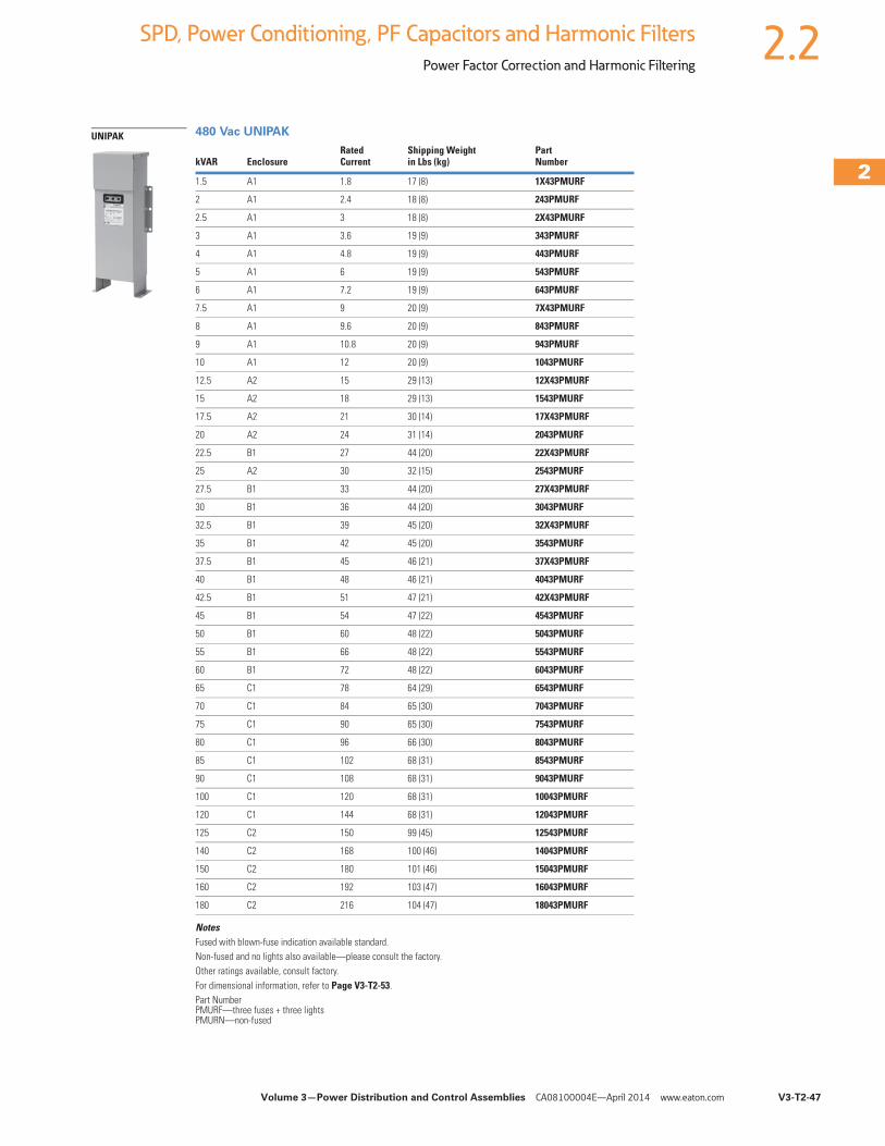
Volume 3—Power Distribution and Control Assemblies CA08100004E—April 2014 www.eaton.com V3-T2-47
2
2
2
2
2
2
2
2
2
2
2
2
2
2
2
2
2
2
2
2
2
2
2
2
2
2
2
2
2
2
2.2SPD, Power Conditioning, PF Capacitors and Harmonic Filters
Power Factor Correction and Harmonic Filtering
480 Vac UNIPAK
NotesFused with blown-fuse indication available standard.Non-fused and no lights also available—please consult the factory.Other ratings available, consult factory.For dimensional information, refer to Page V3-T2-53.Part Number PMURF—three fuses + three lightsPMURN—non-fused
kVAR EnclosureRated Current
Shipping Weight in Lbs (kg)
Part Number
1.5 A1 1.8 17 (8) 1X43PMURF
2 A1 2.4 18 (8) 243PMURF
2.5 A1 3 18 (8) 2X43PMURF
3 A1 3.6 19 (9) 343PMURF
4 A1 4.8 19 (9) 443PMURF
5 A1 6 19 (9) 543PMURF
6 A1 7.2 19 (9) 643PMURF
7.5 A1 9 20 (9) 7X43PMURF
8 A1 9.6 20 (9) 843PMURF
9 A1 10.8 20 (9) 943PMURF
10 A1 12 20 (9) 1043PMURF
12.5 A2 15 29 (13) 12X43PMURF
15 A2 18 29 (13) 1543PMURF
17.5 A2 21 30 (14) 17X43PMURF
20 A2 24 31 (14) 2043PMURF
22.5 B1 27 44 (20) 22X43PMURF
25 A2 30 32 (15) 2543PMURF
27.5 B1 33 44 (20) 27X43PMURF
30 B1 36 44 (20) 3043PMURF
32.5 B1 39 45 (20) 32X43PMURF
35 B1 42 45 (20) 3543PMURF
37.5 B1 45 46 (21) 37X43PMURF
40 B1 48 46 (21) 4043PMURF
42.5 B1 51 47 (21) 42X43PMURF
45 B1 54 47 (22) 4543PMURF
50 B1 60 48 (22) 5043PMURF
55 B1 66 48 (22) 5543PMURF
60 B1 72 48 (22) 6043PMURF
65 C1 78 64 (29) 6543PMURF
70 C1 84 65 (30) 7043PMURF
75 C1 90 65 (30) 7543PMURF
80 C1 96 66 (30) 8043PMURF
85 C1 102 68 (31) 8543PMURF
90 C1 108 68 (31) 9043PMURF
100 C1 120 68 (31) 10043PMURF
120 C1 144 68 (31) 12043PMURF
125 C2 150 99 (45) 12543PMURF
140 C2 168 100 (46) 14043PMURF
150 C2 180 101 (46) 15043PMURF
160 C2 192 103 (47) 16043PMURF
180 C2 216 104 (47) 18043PMURF
UNIPAK
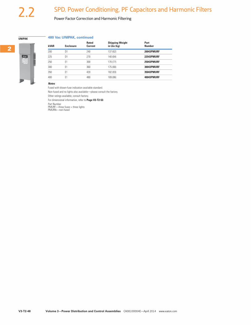
V3-T2-48 Volume 3—Power Distribution and Control Assemblies CA08100004E—April 2014 www.eaton.com
2
2
2
2
2
2
2
2
2
2
2
2
2
2
2
2
2
2
2
2
2
2
2
2
2
2
2
2
2
2
2.2 SPD, Power Conditioning, PF Capacitors and Harmonic Filters
Power Factor Correction and Harmonic Filtering
480 Vac UNIPAK, continued
NotesFused with blown-fuse indication available standard.Non-fused and no lights also available—please consult the factory.Other ratings available, consult factory.For dimensional information, refer to Page V3-T2-53.Part Number PMURF—three fuses + three lightsPMURN—non-fused
kVAR EnclosureRated Current
Shipping Weight in Lbs (kg)
Part Number
200 D1 240 137 (62) 20043PMURF
225 D1 270 140 (64) 22543PMURF
250 E1 300 170 (77) 25043PMURF
300 E1 360 175 (80) 30043PMURF
350 E1 420 182 (83) 35043PMURF
400 E1 480 189 (86) 40043PMURF
UNIPAK
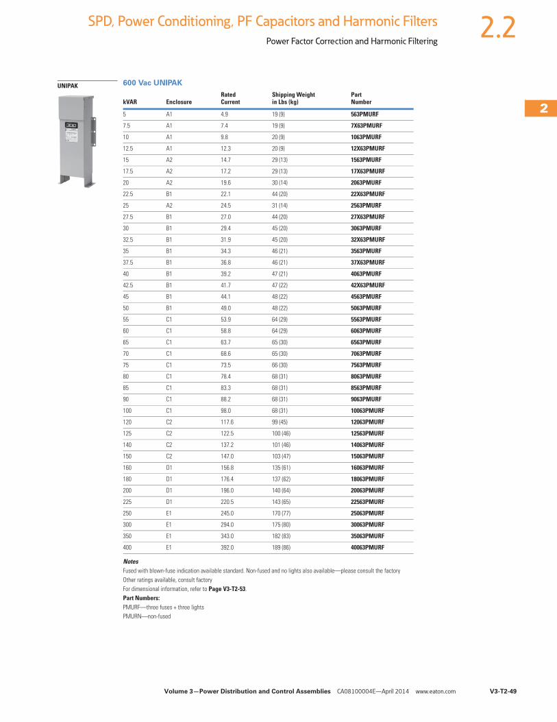
Volume 3—Power Distribution and Control Assemblies CA08100004E—April 2014 www.eaton.com V3-T2-49
2
2
2
2
2
2
2
2
2
2
2
2
2
2
2
2
2
2
2
2
2
2
2
2
2
2
2
2
2
2
2.2SPD, Power Conditioning, PF Capacitors and Harmonic Filters
Power Factor Correction and Harmonic Filtering
600 Vac UNIPAK
NotesFused with blown-fuse indication available standard. Non-fused and no lights also available—please consult the factoryOther ratings available, consult factoryFor dimensional information, refer to Page V3-T2-53.Part Numbers:PMURF—three fuses + three lightsPMURN—non-fused
kVAR EnclosureRatedCurrent
Shipping Weightin Lbs (kg)
PartNumber
5 A1 4.9 19 (9) 563PMURF
7.5 A1 7.4 19 (9) 7X63PMURF
10 A1 9.8 20 (9) 1063PMURF
12.5 A1 12.3 20 (9) 12X63PMURF
15 A2 14.7 29 (13) 1563PMURF
17.5 A2 17.2 29 (13) 17X63PMURF
20 A2 19.6 30 (14) 2063PMURF
22.5 B1 22.1 44 (20) 22X63PMURF
25 A2 24.5 31 (14) 2563PMURF
27.5 B1 27.0 44 (20) 27X63PMURF
30 B1 29.4 45 (20) 3063PMURF
32.5 B1 31.9 45 (20) 32X63PMURF
35 B1 34.3 46 (21) 3563PMURF
37.5 B1 36.8 46 (21) 37X63PMURF
40 B1 39.2 47 (21) 4063PMURF
42.5 B1 41.7 47 (22) 42X63PMURF
45 B1 44.1 48 (22) 4563PMURF
50 B1 49.0 48 (22) 5063PMURF
55 C1 53.9 64 (29) 5563PMURF
60 C1 58.8 64 (29) 6063PMURF
65 C1 63.7 65 (30) 6563PMURF
70 C1 68.6 65 (30) 7063PMURF
75 C1 73.5 66 (30) 7563PMURF
80 C1 78.4 68 (31) 8063PMURF
85 C1 83.3 68 (31) 8563PMURF
90 C1 88.2 68 (31) 9063PMURF
100 C1 98.0 68 (31) 10063PMURF
120 C2 117.6 99 (45) 12063PMURF
125 C2 122.5 100 (46) 12563PMURF
140 C2 137.2 101 (46) 14063PMURF
150 C2 147.0 103 (47) 15063PMURF
160 D1 156.8 135 (61) 16063PMURF
180 D1 176.4 137 (62) 18063PMURF
200 D1 196.0 140 (64) 20063PMURF
225 D1 220.5 143 (65) 22563PMURF
250 E1 245.0 170 (77) 25063PMURF
300 E1 294.0 175 (80) 30063PMURF
350 E1 343.0 182 (83) 35063PMURF
400 E1 392.0 189 (86) 40063PMURF
UNIPAK
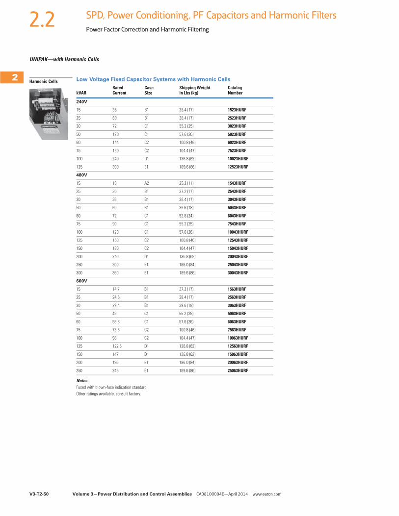
V3-T2-50 Volume 3—Power Distribution and Control Assemblies CA08100004E—April 2014 www.eaton.com
2
2
2
2
2
2
2
2
2
2
2
2
2
2
2
2
2
2
2
2
2
2
2
2
2
2
2
2
2
2
2.2 SPD, Power Conditioning, PF Capacitors and Harmonic Filters
Power Factor Correction and Harmonic Filtering
UNIPAK—with Harmonic Cells
Low Voltage Fixed Capacitor Systems with Harmonic Cells
NotesFused with blown-fuse indication standard.Other ratings available, consult factory.
kVARRatedCurrent
CaseSize
Shipping Weightin Lbs (kg)
CatalogNumber
240V
15 36 B1 38.4 (17) 1523HURF
25 60 B1 38.4 (17) 2523HURF
30 72 C1 55.2 (25) 3023HURF
50 120 C1 57.6 (26) 5023HURF
60 144 C2 100.8 (46) 6023HURF
75 180 C2 104.4 (47) 7523HURF
100 240 D1 136.8 (62) 10023HURF
125 300 E1 189.6 (86) 12523HURF
480V
15 18 A2 25.2 (11) 1543HURF
25 30 B1 37.2 (17) 2543HURF
30 36 B1 38.4 (17) 3043HURF
50 60 B1 39.6 (18) 5043HURF
60 72 C1 52.8 (24) 6043HURF
75 90 C1 55.2 (25) 7543HURF
100 120 C1 57.6 (26) 10043HURF
125 150 C2 100.8 (46) 12543HURF
150 180 C2 104.4 (47) 15043HURF
200 240 D1 136.8 (62) 20043HURF
250 300 E1 186.0 (84) 25043HURF
300 360 E1 189.6 (86) 30043HURF
600V
15 14.7 B1 37.2 (17) 1563HURF
25 24.5 B1 38.4 (17) 2563HURF
30 29.4 B1 39.6 (18) 3063HURF
50 49 C1 55.2 (25) 5063HURF
60 58.8 C1 57.6 (26) 6063HURF
75 73.5 C2 100.8 (46) 7563HURF
100 98 C2 104.4 (47) 10063HURF
125 122.5 D1 136.8 (62) 12563HURF
150 147 D1 136.8 (62) 15063HURF
200 196 E1 186.0 (84) 20063HURF
250 245 E1 189.6 (86) 25063HURF
Harmonic Cells
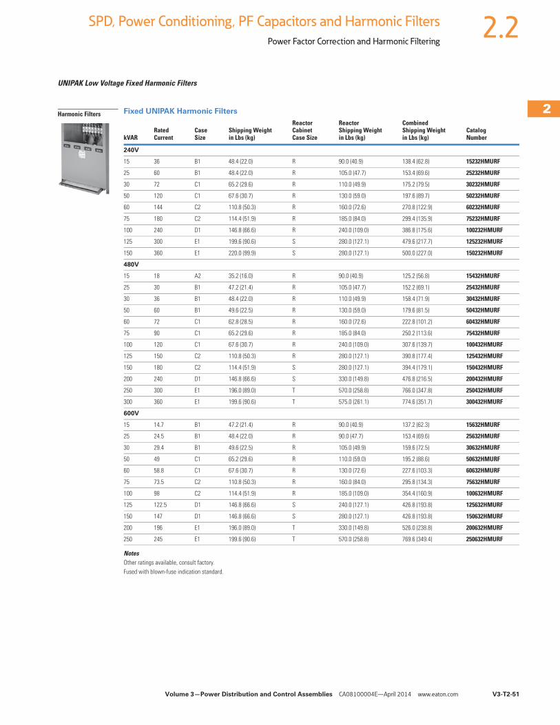
Volume 3—Power Distribution and Control Assemblies CA08100004E—April 2014 www.eaton.com V3-T2-51
2
2
2
2
2
2
2
2
2
2
2
2
2
2
2
2
2
2
2
2
2
2
2
2
2
2
2
2
2
2
2.2SPD, Power Conditioning, PF Capacitors and Harmonic Filters
Power Factor Correction and Harmonic Filtering
UNIPAK Low Voltage Fixed Harmonic Filters
Fixed UNIPAK Harmonic Filters
NotesOther ratings available, consult factory.Fused with blown-fuse indication standard.
kVARRatedCurrent
CaseSize
Shipping Weightin Lbs (kg)
Reactor CabinetCase Size
ReactorShipping Weightin Lbs (kg)
CombinedShipping Weightin Lbs (kg)
Catalog Number
240V
15 36 B1 48.4 (22.0) R 90.0 (40.9) 138.4 (62.8) 15232HMURF
25 60 B1 48.4 (22.0) R 105.0 (47.7) 153.4 (69.6) 25232HMURF
30 72 C1 65.2 (29.6) R 110.0 (49.9) 175.2 (79.5) 30232HMURF
50 120 C1 67.6 (30.7) R 130.0 (59.0) 197.6 (89.7) 50232HMURF
60 144 C2 110.8 (50.3) R 160.0 (72.6) 270.8 (122.9) 60232HMURF
75 180 C2 114.4 (51.9) R 185.0 (84.0) 299.4 (135.9) 75232HMURF
100 240 D1 146.8 (66.6) R 240.0 (109.0) 386.8 (175.6) 100232HMURF
125 300 E1 199.6 (90.6) S 280.0 (127.1) 479.6 (217.7) 125232HMURF
150 360 E1 220.0 (99.9) S 280.0 (127.1) 500.0 (227.0) 150232HMURF
480V
15 18 A2 35.2 (16.0) R 90.0 (40.9) 125.2 (56.8) 15432HMURF
25 30 B1 47.2 (21.4) R 105.0 (47.7) 152.2 (69.1) 25432HMURF
30 36 B1 48.4 (22.0) R 110.0 (49.9) 158.4 (71.9) 30432HMURF
50 60 B1 49.6 (22.5) R 130.0 (59.0) 179.6 (81.5) 50432HMURF
60 72 C1 62.8 (28.5) R 160.0 (72.6) 222.8 (101.2) 60432HMURF
75 90 C1 65.2 (29.6) R 185.0 (84.0) 250.2 (113.6) 75432HMURF
100 120 C1 67.6 (30.7) R 240.0 (109.0) 307.6 (139.7) 100432HMURF
125 150 C2 110.8 (50.3) R 280.0 (127.1) 390.8 (177.4) 125432HMURF
150 180 C2 114.4 (51.9) S 280.0 (127.1) 394.4 (179.1) 150432HMURF
200 240 D1 146.8 (66.6) S 330.0 (149.8) 476.8 (216.5) 200432HMURF
250 300 E1 196.0 (89.0) T 570.0 (258.8) 766.0 (347.8) 250432HMURF
300 360 E1 199.6 (90.6) T 575.0 (261.1) 774.6 (351.7) 300432HMURF
600V
15 14.7 B1 47.2 (21.4) R 90.0 (40.9) 137.2 (62.3) 15632HMURF
25 24.5 B1 48.4 (22.0) R 90.0 (47.7) 153.4 (69.6) 25632HMURF
30 29.4 B1 49.6 (22.5) R 105.0 (49.9) 159.6 (72.5) 30632HMURF
50 49 C1 65.2 (29.6) R 110.0 (59.0) 195.2 (88.6) 50632HMURF
60 58.8 C1 67.6 (30.7) R 130.0 (72.6) 227.6 (103.3) 60632HMURF
75 73.5 C2 110.8 (50.3) R 160.0 (84.0) 295.8 (134.3) 75632HMURF
100 98 C2 114.4 (51.9) R 185.0 (109.0) 354.4 (160.9) 100632HMURF
125 122.5 D1 146.8 (66.6) S 240.0 (127.1) 426.8 (193.8) 125632HMURF
150 147 D1 146.8 (66.6) S 280.0 (127.1) 426.8 (193.8) 150632HMURF
200 196 E1 196.0 (89.0) T 330.0 (149.8) 526.0 (238.8) 200632HMURF
250 245 E1 199.6 (90.6) T 570.0 (258.8) 769.6 (349.4) 250632HMURF
Harmonic Filters
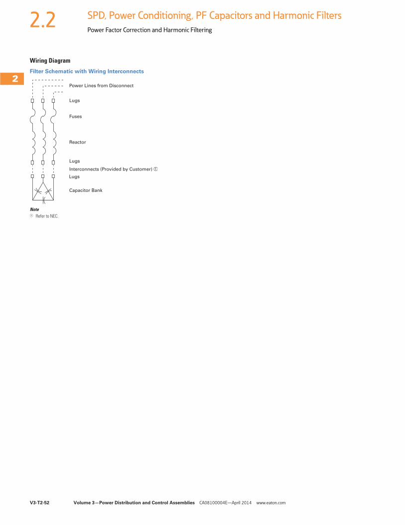
V3-T2-52 Volume 3—Power Distribution and Control Assemblies CA08100004E—April 2014 www.eaton.com
2
2
2
2
2
2
2
2
2
2
2
2
2
2
2
2
2
2
2
2
2
2
2
2
2
2
2
2
2
2
2.2 SPD, Power Conditioning, PF Capacitors and Harmonic Filters
Power Factor Correction and Harmonic Filtering
Wiring Diagram
Filter Schematic with Wiring Interconnects
Note1 Refer to NEC.
Power Lines from Disconnect
Lugs
Fuses
Reactor
Lugs
Lugs
Interconnects (Provided by Customer) a
Capacitor Bank
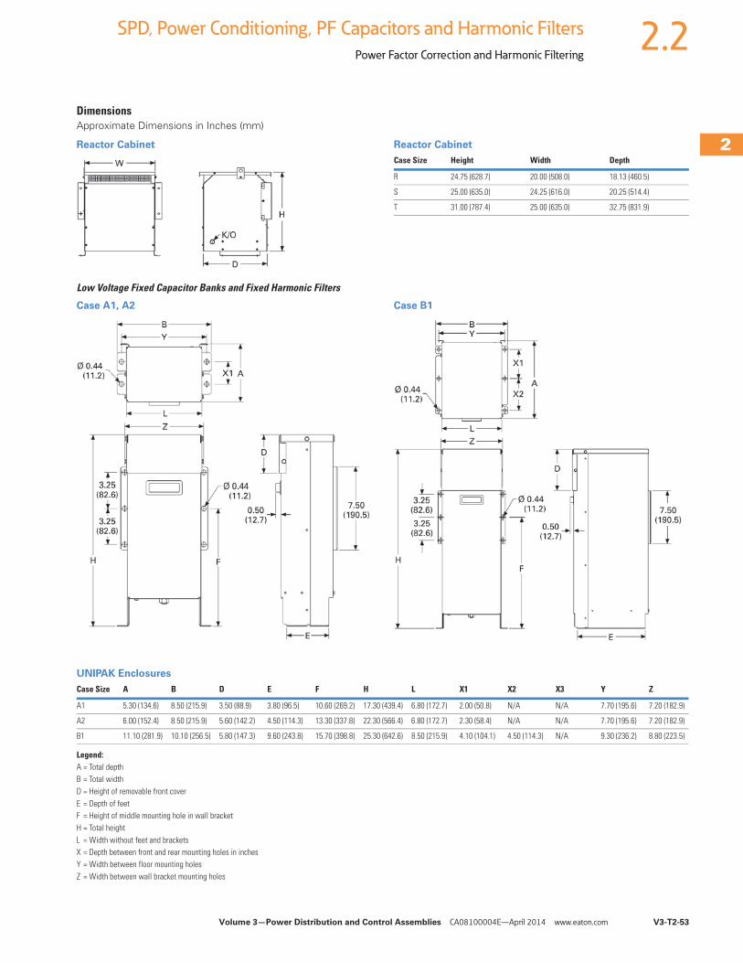
Volume 3—Power Distribution and Control Assemblies CA08100004E—April 2014 www.eaton.com V3-T2-53
2
2
2
2
2
2
2
2
2
2
2
2
2
2
2
2
2
2
2
2
2
2
2
2
2
2
2
2
2
2
2.2SPD, Power Conditioning, PF Capacitors and Harmonic Filters
Power Factor Correction and Harmonic Filtering
DimensionsApproximate Dimensions in Inches (mm)
Reactor Cabinet Reactor Cabinet
Low Voltage Fixed Capacitor Banks and Fixed Harmonic Filters
Case A1, A2 Case B1
UNIPAK Enclosures
Legend:A = Total depthB = Total widthD = Height of removable front coverE = Depth of feetF = Height of middle mounting hole in wall bracketH = Total heightL = Width without feet and bracketsX = Depth between front and rear mounting holes in inchesY = Width between floor mounting holesZ = Width between wall bracket mounting holes
Case Size Height Width Depth
R 24.75 (628.7) 20.00 (508.0) 18.13 (460.5)
S 25.00 (635.0) 24.25 (616.0) 20.25 (514.4)
T 31.00 (787.4) 25.00 (635.0) 32.75 (831.9)
Case Size A B D E F H L X1 X2 X3 Y Z
A1 5.30 (134.6) 8.50 (215.9) 3.50 (88.9) 3.80 (96.5) 10.60 (269.2) 17.30 (439.4) 6.80 (172.7) 2.00 (50.8) N/A N/A 7.70 (195.6) 7.20 (182.9)
A2 6.00 (152.4) 8.50 (215.9) 5.60 (142.2) 4.50 (114.3) 13.30 (337.8) 22.30 (566.4) 6.80 (172.7) 2.30 (58.4) N/A N/A 7.70 (195.6) 7.20 (182.9)
B1 11.10 (281.9) 10.10 (256.5) 5.80 (147.3) 9.60 (243.8) 15.70 (398.8) 25.30 (642.6) 8.50 (215.9) 4.10 (104.1) 4.50 (114.3) N/A 9.30 (236.2) 8.80 (223.5)
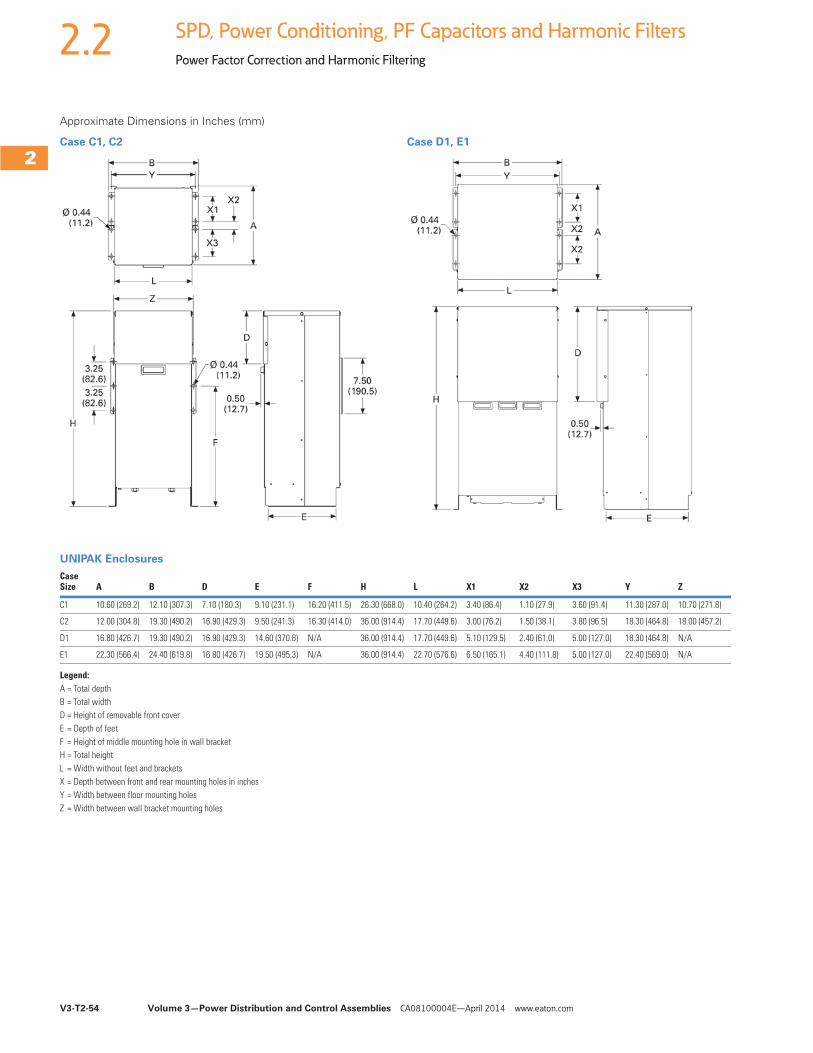
V3-T2-54 Volume 3—Power Distribution and Control Assemblies CA08100004E—April 2014 www.eaton.com
2
2
2
2
2
2
2
2
2
2
2
2
2
2
2
2
2
2
2
2
2
2
2
2
2
2
2
2
2
2
2.2 SPD, Power Conditioning, PF Capacitors and Harmonic Filters
Power Factor Correction and Harmonic Filtering
Approximate Dimensions in Inches (mm)
Case C1, C2 Case D1, E1
UNIPAK Enclosures
Legend:A = Total depthB = Total widthD = Height of removable front coverE = Depth of feetF = Height of middle mounting hole in wall bracketH = Total heightL = Width without feet and bracketsX = Depth between front and rear mounting holes in inchesY = Width between floor mounting holesZ = Width between wall bracket mounting holes
CaseSize A B D E F H L X1 X2 X3 Y Z
C1 10.60 (269.2) 12.10 (307.3) 7.10 (180.3) 9.10 (231.1) 16.20 (411.5) 26.30 (668.0) 10.40 (264.2) 3.40 (86.4) 1.10 (27.9) 3.60 (91.4) 11.30 (287.0) 10.70 (271.8)
C2 12.00 (304.8) 19.30 (490.2) 16.90 (429.3) 9.50 (241.3) 16.30 (414.0) 36.00 (914.4) 17.70 (449.6) 3.00 (76.2) 1.50 (38.1) 3.80 (96.5) 18.30 (464.8) 18.00 (457.2)
D1 16.80 (426.7) 19.30 (490.2) 16.90 (429.3) 14.60 (370.8) N/A 36.00 (914.4) 17.70 (449.6) 5.10 (129.5) 2.40 (61.0) 5.00 (127.0) 18.30 (464.8) N/A
E1 22.30 (566.4) 24.40 (619.8) 16.80 (426.7) 19.50 (495.3) N/A 36.00 (914.4) 22.70 (576.6) 6.50 (165.1) 4.40 (111.8) 5.00 (127.0) 22.40 (569.0) N/A
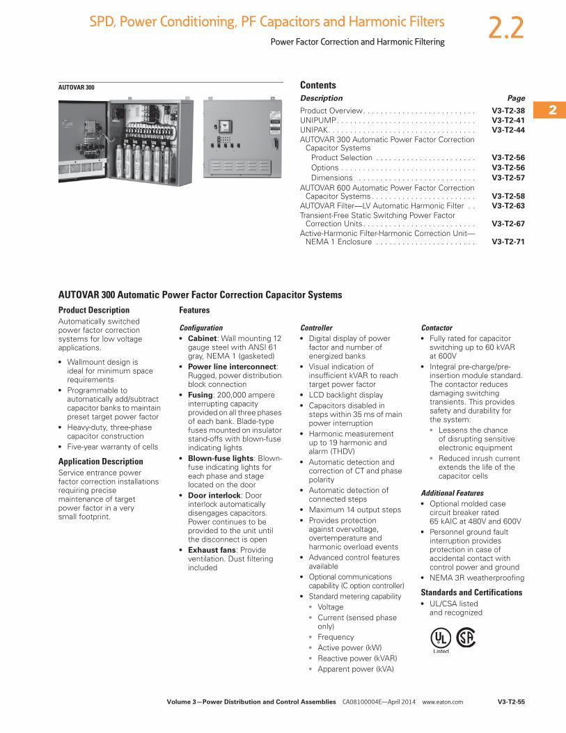
Volume 3—Power Distribution and Control Assemblies CA08100004E—April 2014 www.eaton.com V3-T2-55
2
2
2
2
2
2
2
2
2
2
2
2
2
2
2
2
2
2
2
2
2
2
2
2
2
2
2
2
2
2
2.2SPD, Power Conditioning, PF Capacitors and Harmonic Filters
Power Factor Correction and Harmonic Filtering
AUTOVAR 300 ContentsDescription Page
Product Overview. . . . . . . . . . . . . . . . . . . . . . . . . . V3-T2-38
UNIPUMP. . . . . . . . . . . . . . . . . . . . . . . . . . . . . . . . V3-T2-41
UNIPAK. . . . . . . . . . . . . . . . . . . . . . . . . . . . . . . . . . V3-T2-44
AUTOVAR 300 Automatic Power Factor Correction Capacitor Systems
Product Selection . . . . . . . . . . . . . . . . . . . . . . . V3-T2-56
Options . . . . . . . . . . . . . . . . . . . . . . . . . . . . . . . V3-T2-56
Dimensions . . . . . . . . . . . . . . . . . . . . . . . . . . . V3-T2-57
AUTOVAR 600 Automatic Power Factor Correction Capacitor Systems . . . . . . . . . . . . . . . . . . . . . . . . V3-T2-58
AUTOVAR Filter—LV Automatic Harmonic Filter . . V3-T2-63
Transient-Free Static Switching Power Factor Correction Units . . . . . . . . . . . . . . . . . . . . . . . . . . V3-T2-67
Active-Harmonic Filter-Harmonic Correction Unit—NEMA 1 Enclosure . . . . . . . . . . . . . . . . . . . . . . . V3-T2-71
AUTOVAR 300 Automatic Power Factor Correction Capacitor SystemsProduct DescriptionAutomatically switched power factor correction systems for low voltage applications.
● Wallmount design is ideal for minimum space requirements
● Programmable to automatically add/subtract capacitor banks to maintain preset target power factor
● Heavy-duty, three-phase capacitor construction
● Five-year warranty of cells
Application DescriptionService entrance power factor correction installations requiring precise maintenance of target power factor in a very small footprint.
Features
Configuration● Cabinet: Wall mounting 12
gauge steel with ANSI 61 gray, NEMA 1 (gasketed)
● Power line interconnect: Rugged, power distribution block connection
● Fusing: 200,000 ampere interrupting capacity provided on all three phases of each bank. Blade-type fuses mounted on insulator stand-offs with blown-fuse indicating lights
● Blown-fuse lights: Blown-fuse indicating lights for each phase and stage located on the door
● Door interlock: Door interlock automatically disengages capacitors. Power continues to be provided to the unit until the disconnect is open
● Exhaust fans: Provide ventilation. Dust filtering included
Controller● Digital display of power
factor and number of energized banks
● Visual indication of insufficient kVAR to reach target power factor
● LCD backlight display● Capacitors disabled in
steps within 35 ms of main power interruption
● Harmonic measurement up to 19 harmonic and alarm (THDV)
● Automatic detection and correction of CT and phase polarity
● Automatic detection of connected steps
● Maximum 14 output steps● Provides protection
against overvoltage, overtemperature and harmonic overload events
● Advanced control features available
● Optional communications capability (C option controller)
● Standard metering capability● Voltage● Current (sensed phase
only)● Frequency● Active power (kW)● Reactive power (kVAR)● Apparent power (kVA)
Contactor● Fully rated for capacitor
switching up to 60 kVAR at 600V
● Integral pre-charge/pre-insertion module standard. The contactor reduces damaging switching transients. This provides safety and durability for the system:● Lessens the chance
of disrupting sensitive electronic equipment
● Reduced inrush current extends the life of the capacitor cells
Additional Features● Optional molded case
circuit breaker rated 65 kAIC at 480V and 600V
● Personnel ground fault interruption provides protection in case of accidental contact with control power and ground
● NEMA 3R weatherproofing
Standards and Certifications● UL/CSA listed
and recognized
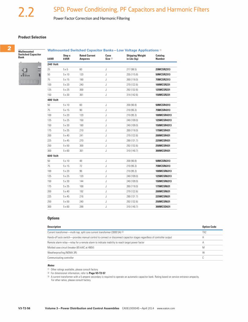
V3-T2-56 Volume 3—Power Distribution and Control Assemblies CA08100004E—April 2014 www.eaton.com
2
2
2
2
2
2
2
2
2
2
2
2
2
2
2
2
2
2
2
2
2
2
2
2
2
2
2
2
2
2
2.2 SPD, Power Conditioning, PF Capacitors and Harmonic Filters
Power Factor Correction and Harmonic Filtering
Product Selection
Wallmounted Switched Capacitor Banks—Low Voltage Applications 1
Options
Notes1 Other ratings available, please consult factory.2 For dimensional information, refer to Page V3-T2-57.3 A current transformer with a 5 ampere secondary is required to operate an automatic capacitor bank. Rating based on service entrance ampacity.
For other ratios, please consult factory.
kVARStep x kVAR
Rated CurrentAmperes
CaseSize 2
Shipping Weightin Lbs (kg)
Catalog Number
240 Volt
25 5 x 5 60 J 217 (98.5) 25MCSR2313
50 5 x 10 120 J 255 (115.8) 50MCSR2313
75 5 x 15 180 J 260 (118.0) 75MCSR2313
100 5 x 20 240 J 270 (122.6) 100MCSR231
125 5 x 25 300 J 292 (132.6) 125MCSR231
150 5 x 30 361 J 314 (142.6) 150MCSR231
480 Volt
50 5 x 10 60 J 200 (90.8) 50MCSR4313
75 5 x 15 90 J 210 (95.3) 75MCSR4313
100 5 x 20 120 J 210 (95.3) 100MCSR4313
125 5 x 25 150 J 240 (109.0) 125MCSR4313
150 5 x 30 180 J 240 (109.0) 150MCSR4313
175 5 x 35 210 J 260 (118.0) 175MCSR431
200 5 x 40 241 J 270 (122.6) 200MCSR431
225 5 x 45 270 J 290 (131.7) 225MCSR431
250 5 x 50 300 J 292 (132.6) 250MCSR431
300 5 x 60 361 J 310 (140.7) 300MCSR431
600 Volt
50 5 x 10 48 J 200 (90.8) 50MCSR6313
75 5 x 15 72 J 210 (95.3) 75MCSR6313
100 5 x 20 96 J 210 (95.3) 100MCSR6313
125 5 x 25 120 J 240 (109.0) 125MCSR6313
150 5 x 30 144 J 240 (109.0) 150MCSR6313
175 5 x 35 168 J 260 (118.0) 175MCSR631
200 5 x 40 192 J 270 (122.6) 200MCSR631
225 5 x 45 216 J 290 (131.7) 225MCSR631
250 5 x 50 240 J 292 (132.6) 250MCSR631
300 5 x 60 288 J 310 (140.7) 300MCSD631
Description Option Code
Current transformer—multi-tap, split core current transformer (3000:5A) 3 TX2
Hands-off auto switch—provides manual control to connect or disconnect capacitor stages regardless of controller output H
Remote alarm relay—relay for a remote alarm to indicate inability to reach target power factor A
Molded case circuit breaker (65 kAIC at 480V) M
Weatherproofing (NEMA 3R) W
Communicating controller C
Wallmounted Switched Capacitor Bank
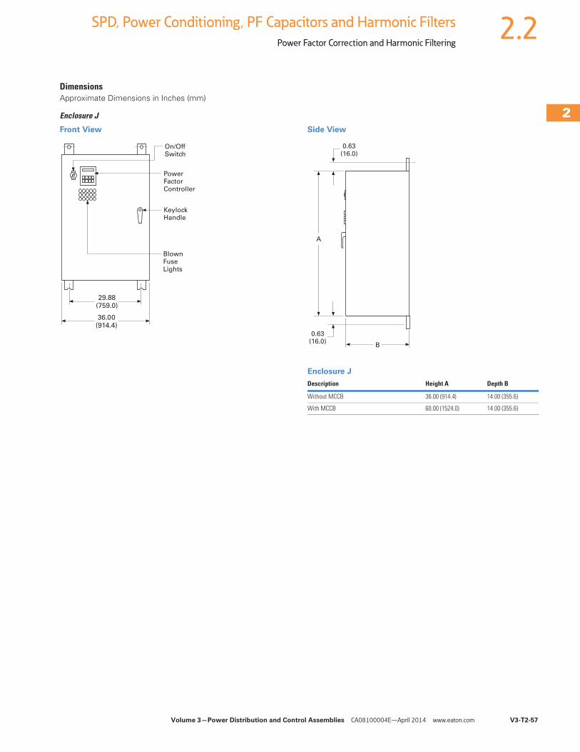
Volume 3—Power Distribution and Control Assemblies CA08100004E—April 2014 www.eaton.com V3-T2-57
2
2
2
2
2
2
2
2
2
2
2
2
2
2
2
2
2
2
2
2
2
2
2
2
2
2
2
2
2
2
2.2SPD, Power Conditioning, PF Capacitors and Harmonic Filters
Power Factor Correction and Harmonic Filtering
DimensionsApproximate Dimensions in Inches (mm)
Enclosure J
Front View Side View
Enclosure J
36.00(914.4)
29.88(759.0)
On/OffSwitch
PowerFactorController
KeylockHandle
BlownFuseLights
Description Height A Depth B
Without MCCB 36.00 (914.4) 14.00 (355.6)
With MCCB 60.00 (1524.0) 14.00 (355.6)
A
B
0.63(16.0)
0.63(16.0)
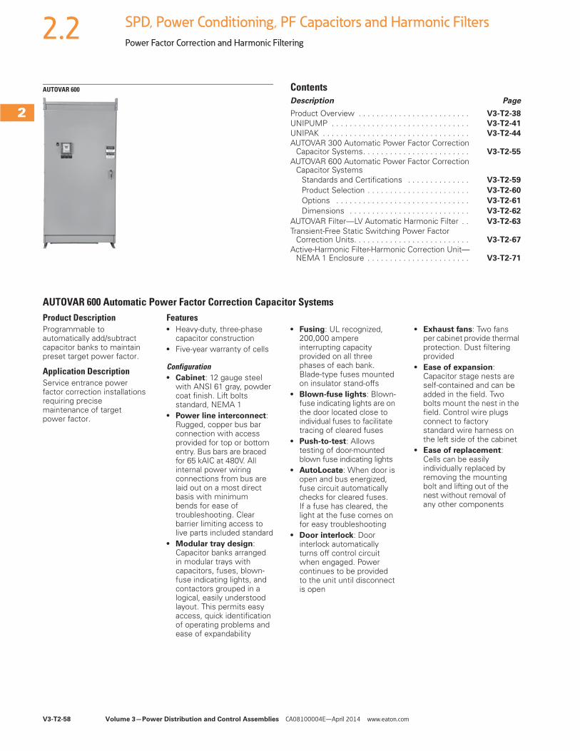
V3-T2-58 Volume 3—Power Distribution and Control Assemblies CA08100004E—April 2014 www.eaton.com
2
2
2
2
2
2
2
2
2
2
2
2
2
2
2
2
2
2
2
2
2
2
2
2
2
2
2
2
2
2
2.2 SPD, Power Conditioning, PF Capacitors and Harmonic Filters
Power Factor Correction and Harmonic Filtering
AUTOVAR 600 ContentsDescription Page
Product Overview . . . . . . . . . . . . . . . . . . . . . . . . . V3-T2-38
UNIPUMP . . . . . . . . . . . . . . . . . . . . . . . . . . . . . . . V3-T2-41
UNIPAK . . . . . . . . . . . . . . . . . . . . . . . . . . . . . . . . . V3-T2-44
AUTOVAR 300 Automatic Power Factor Correction Capacitor Systems. . . . . . . . . . . . . . . . . . . . . . . . V3-T2-55
AUTOVAR 600 Automatic Power Factor Correction Capacitor Systems
Standards and Certifications . . . . . . . . . . . . . . V3-T2-59
Product Selection . . . . . . . . . . . . . . . . . . . . . . . V3-T2-60
Options . . . . . . . . . . . . . . . . . . . . . . . . . . . . . . V3-T2-61
Dimensions . . . . . . . . . . . . . . . . . . . . . . . . . . . V3-T2-62
AUTOVAR Filter—LV Automatic Harmonic Filter . . V3-T2-63
Transient-Free Static Switching Power Factor Correction Units. . . . . . . . . . . . . . . . . . . . . . . . . . V3-T2-67
Active-Harmonic Filter-Harmonic Correction Unit—NEMA 1 Enclosure . . . . . . . . . . . . . . . . . . . . . . . V3-T2-71
AUTOVAR 600 Automatic Power Factor Correction Capacitor SystemsProduct DescriptionProgrammable to automatically add/subtract capacitor banks to maintain preset target power factor.
Application DescriptionService entrance power factor correction installations requiring precise maintenance of target power factor.
Features ● Heavy-duty, three-phase
capacitor construction● Five-year warranty of cells
Configuration● Cabinet: 12 gauge steel
with ANSI 61 gray, powder coat finish. Lift bolts standard, NEMA 1
● Power line interconnect: Rugged, copper bus bar connection with access provided for top or bottom entry. Bus bars are braced for 65 kAIC at 480V. All internal power wiring connections from bus are laid out on a most direct basis with minimum bends for ease of troubleshooting. Clear barrier limiting access to live parts included standard
● Modular tray design: Capacitor banks arranged in modular trays with capacitors, fuses, blown-fuse indicating lights, and contactors grouped in a logical, easily understood layout. This permits easy access, quick identification of operating problems and ease of expandability
● Fusing: UL recognized, 200,000 ampere interrupting capacity provided on all three phases of each bank. Blade-type fuses mounted on insulator stand-offs
● Blown-fuse lights: Blown-fuse indicating lights are on the door located close to individual fuses to facilitate tracing of cleared fuses
● Push-to-test: Allows testing of door-mounted blown fuse indicating lights
● AutoLocate: When door is open and bus energized, fuse circuit automatically checks for cleared fuses. If a fuse has cleared, the light at the fuse comes on for easy troubleshooting
● Door interlock: Door interlock automatically turns off control circuit when engaged. Power continues to be provided to the unit until disconnect is open
● Exhaust fans: Two fans per cabinet provide thermal protection. Dust filtering provided
● Ease of expansion: Capacitor stage nests are self-contained and can be added in the field. Two bolts mount the nest in the field. Control wire plugs connect to factory standard wire harness on the left side of the cabinet
● Ease of replacement: Cells can be easily individually replaced by removing the mounting bolt and lifting out of the nest without removal of any other components
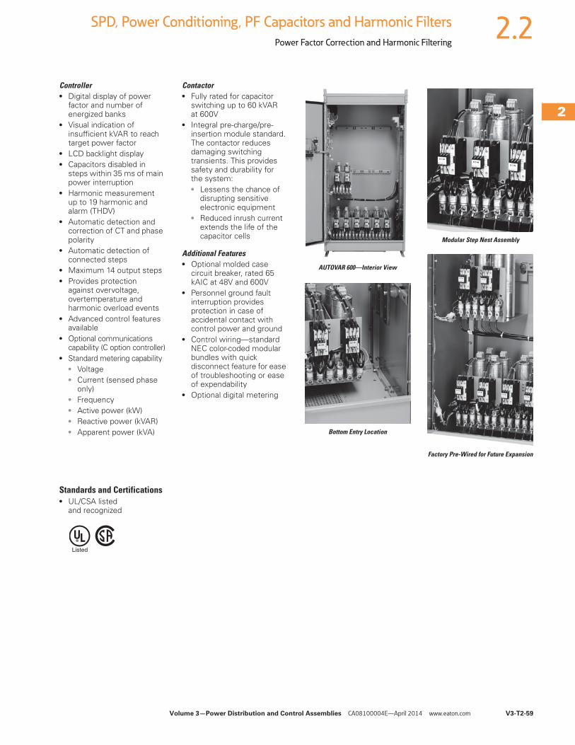
Volume 3—Power Distribution and Control Assemblies CA08100004E—April 2014 www.eaton.com V3-T2-59
2
2
2
2
2
2
2
2
2
2
2
2
2
2
2
2
2
2
2
2
2
2
2
2
2
2
2
2
2
2
2.2SPD, Power Conditioning, PF Capacitors and Harmonic Filters
Power Factor Correction and Harmonic Filtering
Controller● Digital display of power
factor and number of energized banks
● Visual indication of insufficient kVAR to reach target power factor
● LCD backlight display● Capacitors disabled in
steps within 35 ms of main power interruption
● Harmonic measurement up to 19 harmonic and alarm (THDV)
● Automatic detection and correction of CT and phase polarity
● Automatic detection of connected steps
● Maximum 14 output steps● Provides protection
against overvoltage, overtemperature and harmonic overload events
● Advanced control features available
● Optional communications capability (C option controller)
● Standard metering capability● Voltage● Current (sensed phase
only)● Frequency● Active power (kW)● Reactive power (kVAR)● Apparent power (kVA)
Contactor● Fully rated for capacitor
switching up to 60 kVAR at 600V
● Integral pre-charge/pre-insertion module standard. The contactor reduces damaging switching transients. This provides safety and durability for the system:● Lessens the chance of
disrupting sensitive electronic equipment
● Reduced inrush current extends the life of the capacitor cells
Additional Features● Optional molded case
circuit breaker, rated 65 kAIC at 48V and 600V
● Personnel ground fault interruption provides protection in case of accidental contact with control power and ground
● Control wiring—standard NEC color-coded modular bundles with quick disconnect feature for ease of troubleshooting or ease of expendability
● Optional digital metering
AUTOVAR 600—Interior View
Bottom Entry Location
Modular Step Nest Assembly
Factory Pre-Wired for Future Expansion
Standards and Certifications● UL/CSA listed
and recognized
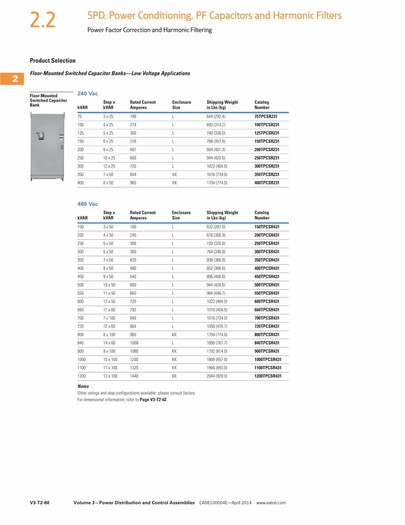
V3-T2-60 Volume 3—Power Distribution and Control Assemblies CA08100004E—April 2014 www.eaton.com
2
2
2
2
2
2
2
2
2
2
2
2
2
2
2
2
2
2
2
2
2
2
2
2
2
2
2
2
2
2
2.2 SPD, Power Conditioning, PF Capacitors and Harmonic Filters
Power Factor Correction and Harmonic Filtering
Product Selection
Floor-Mounted Switched Capacitor Banks—Low Voltage Applications
240 Vac
480 Vac
NotesOther ratings and step configurations available, please consult factory.For dimensional information, refer to Page V3-T2-62.
kVARStep xkVAR
Rated CurrentAmperes
EnclosureSize
Shipping Weightin Lbs (kg)
CatalogNumber
75 3 x 25 180 L 644 (292.4) 75TPCSR231
100 4 x 25 214 L 692 (314.2) 100TPCSR231
125 5 x 25 300 L 740 (336.0) 125TPCSR231
150 6 x 25 316 L 788 (357.8) 150TPCSR231
200 8 x 25 481 L 884 (401.3) 200TPCSR231
250 10 x 25 600 L 944 (428.6) 250TPCSR231
300 12 x 25 720 L 1022 (464.0) 300TPCSR231
350 7 x 50 844 KK 1616 (734.0) 350TPCSR231
400 8 x 50 965 KK 1704 (774.0) 400TPCSR231
kVARStep xkVAR
Rated CurrentAmperes
EnclosureSize
Shipping Weightin Lbs (kg)
CatalogNumber
150 3 x 50 180 L 632 (287.0) 150TPCSR431
200 4 x 50 240 L 676 (306.9) 200TPCSR431
250 5 x 50 300 L 720 (326.9) 250TPCSR431
300 6 x 50 360 L 764 (346.9) 300TPCSR431
350 7 x 50 420 L 808 (366.8) 350TPCSR431
400 8 x 50 480 L 852 (386.8) 400TPCSR431
450 9 x 50 540 L 896 (406.8) 450TPCSR431
500 10 x 50 600 L 944 (428.6) 500TPCSR431
550 11 x 50 660 L 984 (446.7) 550TPCSR431
600 12 x 50 720 L 1022 (464.0) 600TPCSR431
660 11 x 60 792 L 1010 (458.5) 660TPCSR431
700 7 x 100 840 L 1616 (734.0) 700TPCSR431
720 12 x 60 864 L 1050 (476.7) 720TPCSR431
800 8 x 100 960 KK 1704 (774.0) 800TPCSR431
840 14 x 60 1008 L 1690 (767.7) 840TPCSR431
900 9 x 100 1080 KK 1792 (814.0) 900TPCSR431
1000 10 x 100 1200 KK 1888 (857.0) 1000TPCSR431
1100 11 x 100 1320 KK 1966 (893.0) 1100TPCSR431
1200 12 x 100 1440 KK 2044 (928.0) 1200TPCSR431
Floor-Mounted Switched Capacitor Bank
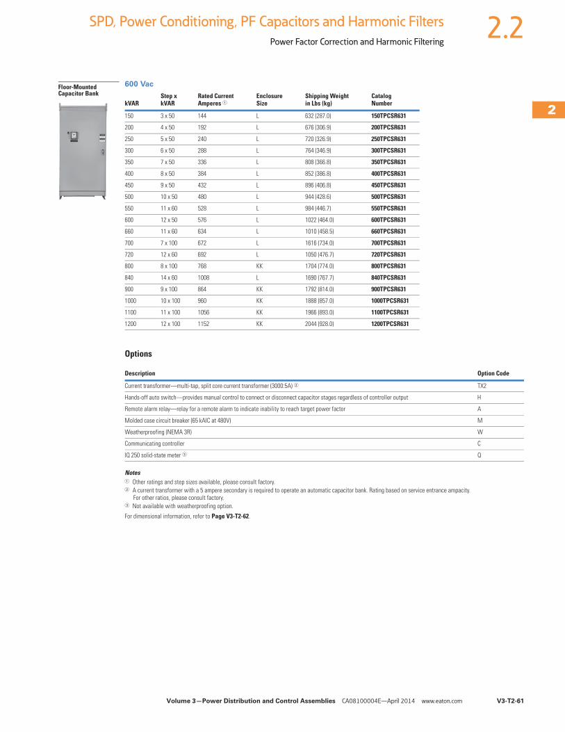
Volume 3—Power Distribution and Control Assemblies CA08100004E—April 2014 www.eaton.com V3-T2-61
2
2
2
2
2
2
2
2
2
2
2
2
2
2
2
2
2
2
2
2
2
2
2
2
2
2
2
2
2
2
2.2SPD, Power Conditioning, PF Capacitors and Harmonic Filters
Power Factor Correction and Harmonic Filtering
600 Vac
Options
Notes1 Other ratings and step sizes available, please consult factory.2 A current transformer with a 5 ampere secondary is required to operate an automatic capacitor bank. Rating based on service entrance ampacity.
For other ratios, please consult factory.3 Not available with weatherproofing option.
For dimensional information, refer to Page V3-T2-62.
kVARStep xkVAR
Rated CurrentAmperes 1
EnclosureSize
Shipping Weightin Lbs (kg)
CatalogNumber
150 3 x 50 144 L 632 (287.0) 150TPCSR631
200 4 x 50 192 L 676 (306.9) 200TPCSR631
250 5 x 50 240 L 720 (326.9) 250TPCSR631
300 6 x 50 288 L 764 (346.9) 300TPCSR631
350 7 x 50 336 L 808 (366.8) 350TPCSR631
400 8 x 50 384 L 852 (386.8) 400TPCSR631
450 9 x 50 432 L 896 (406.8) 450TPCSR631
500 10 x 50 480 L 944 (428.6) 500TPCSR631
550 11 x 60 528 L 984 (446.7) 550TPCSR631
600 12 x 50 576 L 1022 (464.0) 600TPCSR631
660 11 x 60 634 L 1010 (458.5) 660TPCSR631
700 7 x 100 672 L 1616 (734.0) 700TPCSR631
720 12 x 60 692 L 1050 (476.7) 720TPCSR631
800 8 x 100 768 KK 1704 (774.0) 800TPCSR631
840 14 x 60 1008 L 1690 (767.7) 840TPCSR631
900 9 x 100 864 KK 1792 (814.0) 900TPCSR631
1000 10 x 100 960 KK 1888 (857.0) 1000TPCSR631
1100 11 x 100 1056 KK 1966 (893.0) 1100TPCSR631
1200 12 x 100 1152 KK 2044 (928.0) 1200TPCSR631
Description Option Code
Current transformer—multi-tap, split core current transformer (3000:5A) 2 TX2
Hands-off auto switch—provides manual control to connect or disconnect capacitor stages regardless of controller output H
Remote alarm relay—relay for a remote alarm to indicate inability to reach target power factor A
Molded case circuit breaker (65 kAIC at 480V) M
Weatherproofing (NEMA 3R) W
Communicating controller C
IQ 250 solid-state meter 3 Q
Floor-Mounted Capacitor Bank
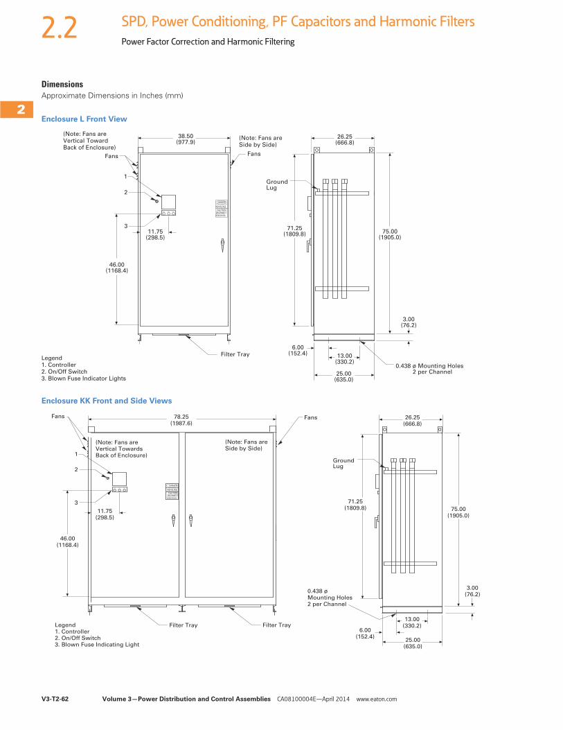
V3-T2-62 Volume 3—Power Distribution and Control Assemblies CA08100004E—April 2014 www.eaton.com
2
2
2
2
2
2
2
2
2
2
2
2
2
2
2
2
2
2
2
2
2
2
2
2
2
2
2
2
2
2
2.2 SPD, Power Conditioning, PF Capacitors and Harmonic Filters
Power Factor Correction and Harmonic Filtering
DimensionsApproximate Dimensions in Inches (mm)
Enclosure L Front View
Enclosure KK Front and Side Views
Fans Fans
46.00(1168.4)
11.75(298.5)
(Note: Fans are Side by Side)
PHASE A PHASE B PHASE C
1
2
3
Filter Tray
BEFORE SERVICING
CAUTIONDISCONNECT
HIGH VOLTAGE
DANGER
75.00(1905.0)
6.00(152.4) 13.00
(330.2)
25.00(635.0)
38.50(977.9)
26.25(666.8)
71.25(1809.8)
3.00(76.2)
GroundLug
0.438 ø Mounting Holes 2 per Channel
Legend1. Controller2. On/Off Switch3. Blown Fuse Indicator Lights
(Note: Fans are Vertical Toward Back of Enclosure)
Fans Fans
(Note: Fans areSide by Side)
46.00(1168.4)
11.75(298.5)
1
2
3
78.25(1987.6)
Filter Tray
25.00(635.0)
13.00(330.2)
0.438 øMounting Holes2 per Channel
Filter Tray6.00
(152.4)
3.00(76.2)
71.25(1809.8) 75.00
(1905.0)
26.25(666.8)
GroundLug
(Note: Fans areVertical TowardsBack of Enclosure)
Legend1. Controller2. On/Off Switch3. Blown Fuse Indicating Light
BEFORE SERVICING
CAUTIONDISCONNECT
HIGH VOLTAGE
DANGERPHASE A PHASE B PHASE C
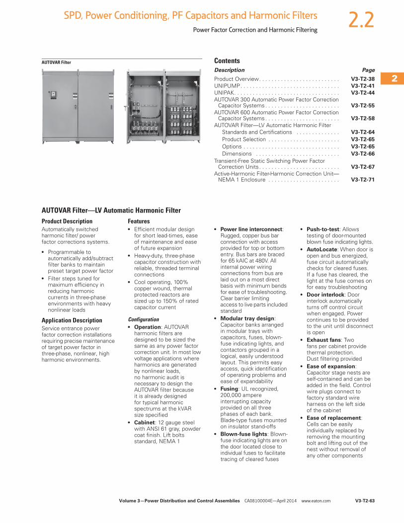
Volume 3—Power Distribution and Control Assemblies CA08100004E—April 2014 www.eaton.com V3-T2-63
2
2
2
2
2
2
2
2
2
2
2
2
2
2
2
2
2
2
2
2
2
2
2
2
2
2
2
2
2
2
2.2SPD, Power Conditioning, PF Capacitors and Harmonic Filters
Power Factor Correction and Harmonic Filtering
AUTOVAR Filter ContentsDescription Page
Product Overview. . . . . . . . . . . . . . . . . . . . . . . . . . V3-T2-38
UNIPUMP. . . . . . . . . . . . . . . . . . . . . . . . . . . . . . . . V3-T2-41
UNIPAK. . . . . . . . . . . . . . . . . . . . . . . . . . . . . . . . . . V3-T2-44
AUTOVAR 300 Automatic Power Factor Correction Capacitor Systems . . . . . . . . . . . . . . . . . . . . . . . . V3-T2-55
AUTOVAR 600 Automatic Power Factor Correction Capacitor Systems . . . . . . . . . . . . . . . . . . . . . . . . V3-T2-58
AUTOVAR Filter—LV Automatic Harmonic FilterStandards and Certifications . . . . . . . . . . . . . . V3-T2-64
Product Selection . . . . . . . . . . . . . . . . . . . . . . . V3-T2-65
Options . . . . . . . . . . . . . . . . . . . . . . . . . . . . . . . V3-T2-65
Dimensions . . . . . . . . . . . . . . . . . . . . . . . . . . . V3-T2-66
Transient-Free Static Switching Power Factor Correction Units . . . . . . . . . . . . . . . . . . . . . . . . . . V3-T2-67
Active-Harmonic Filter-Harmonic Correction Unit—NEMA 1 Enclosure . . . . . . . . . . . . . . . . . . . . . . . V3-T2-71
AUTOVAR Filter—LV Automatic Harmonic FilterProduct DescriptionAutomatically switched harmonic filter/ power factor corrections systems.
● Programmable to automatically add/subtract filter banks to maintain preset target power factor
● Filter steps tuned for maximum efficiency in reducing harmonic currents in three-phase environments with heavy nonlinear loads
Application DescriptionService entrance power factor correction installations requiring precise maintenance of target power factor in three-phase, nonlinear, high harmonic environments.
Features● Efficient modular design
for short lead-times, ease of maintenance and ease of future expansion
● Heavy-duty, three-phase capacitor construction with reliable, threaded terminal connections
● Cool operating, 100% copper wound, thermal protected reactors are sized up to 150% of rated capacitor current
Configuration● Operation: AUTOVAR
harmonic filters are designed to be sized the same as any power factor correction unit. In most low voltage applications where harmonics are generated by nonlinear loads, no harmonic audit is necessary to design the AUTOVAR filter because it is already designed for typical harmonic spectrums at the kVAR size specified
● Cabinet: 12 gauge steel with ANSI 61 gray, powder coat finish. Lift bolts standard, NEMA 1
● Power line interconnect: Rugged, copper bus bar connection with access provided for top or bottom entry. Bus bars are braced for 65 kAIC at 480V. All internal power wiring connections from bus are laid out on a most direct basis with minimum bends for ease of troubleshooting. Clear barrier limiting access to live parts included standard
● Modular tray design: Capacitor banks arranged in modular trays with capacitors, fuses, blown-fuse indicating lights, and contactors grouped in a logical, easily understood layout. This permits easy access, quick identification of operating problems and ease of expandability
● Fusing: UL recognized, 200,000 ampere interrupting capacity provided on all three phases of each bank. Blade-type fuses mounted on insulator stand-offs
● Blown-fuse lights: Blown-fuse indicating lights are on the door located close to individual fuses to facilitate tracing of cleared fuses
● Push-to-test: Allows testing of door-mounted blown fuse indicating lights.
● AutoLocate: When door is open and bus energized, fuse circuit automatically checks for cleared fuses. If a fuse has cleared, the light at the fuse comes on for easy troubleshooting
● Door interlock: Door interlock automatically turns off control circuit when engaged. Power continues to be provided to the unit until disconnect is open
● Exhaust fans: Two fans per cabinet provide thermal protection. Dust filtering provided
● Ease of expansion: Capacitor stage nests are self-contained and can be added in the field. Control wire plugs connect to factory standard wire harness on the left side of the cabinet
● Ease of replacement: Cells can be easily individually replaced by removing the mounting bolt and lifting out of the nest without removal of any other components
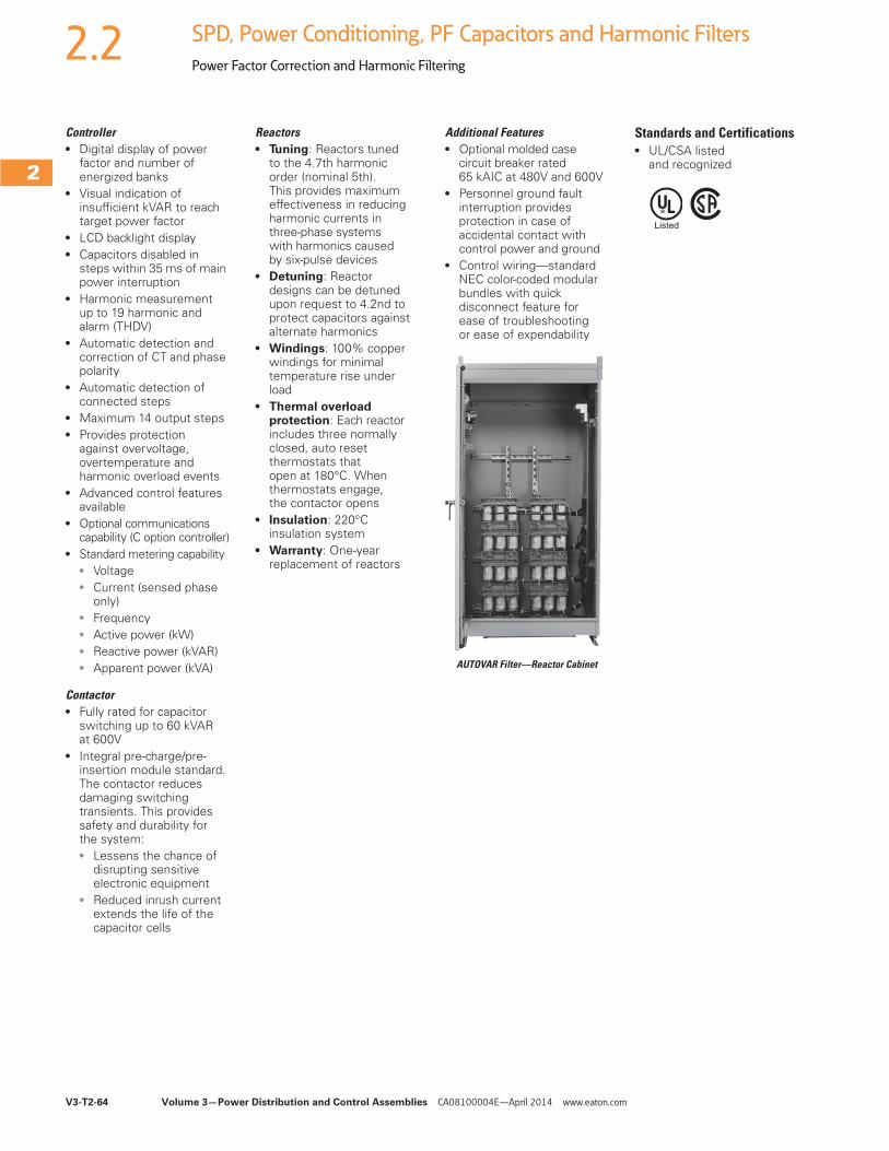
V3-T2-64 Volume 3—Power Distribution and Control Assemblies CA08100004E—April 2014 www.eaton.com
2
2
2
2
2
2
2
2
2
2
2
2
2
2
2
2
2
2
2
2
2
2
2
2
2
2
2
2
2
2
2.2 SPD, Power Conditioning, PF Capacitors and Harmonic Filters
Power Factor Correction and Harmonic Filtering
Controller● Digital display of power
factor and number of energized banks
● Visual indication of insufficient kVAR to reach target power factor
● LCD backlight display● Capacitors disabled in
steps within 35 ms of main power interruption
● Harmonic measurement up to 19 harmonic and alarm (THDV)
● Automatic detection and correction of CT and phase polarity
● Automatic detection of connected steps
● Maximum 14 output steps● Provides protection
against overvoltage, overtemperature and harmonic overload events
● Advanced control features available
● Optional communications capability (C option controller)
● Standard metering capability● Voltage● Current (sensed phase
only)● Frequency● Active power (kW)● Reactive power (kVAR)● Apparent power (kVA)
Contactor● Fully rated for capacitor
switching up to 60 kVAR at 600V
● Integral pre-charge/pre-insertion module standard. The contactor reduces damaging switching transients. This provides safety and durability for the system:● Lessens the chance of
disrupting sensitive electronic equipment
● Reduced inrush current extends the life of the capacitor cells
Reactors● Tuning: Reactors tuned
to the 4.7th harmonic order (nominal 5th). This provides maximum effectiveness in reducing harmonic currents in three-phase systems with harmonics caused by six-pulse devices
● Detuning: Reactor designs can be detuned upon request to 4.2nd to protect capacitors against alternate harmonics
● Windings: 100% copper windings for minimal temperature rise under load
● Thermal overload protection: Each reactor includes three normally closed, auto reset thermostats that open at 180°C. When thermostats engage, the contactor opens
● Insulation: 220°C insulation system
● Warranty: One-year replacement of reactors
Additional Features● Optional molded case
circuit breaker rated 65 kAIC at 480V and 600V
● Personnel ground fault interruption provides protection in case of accidental contact with control power and ground
● Control wiring—standard NEC color-coded modular bundles with quick disconnect feature for ease of troubleshooting or ease of expendability
AUTOVAR Filter—Reactor Cabinet
Standards and Certifications● UL/CSA listed
and recognized
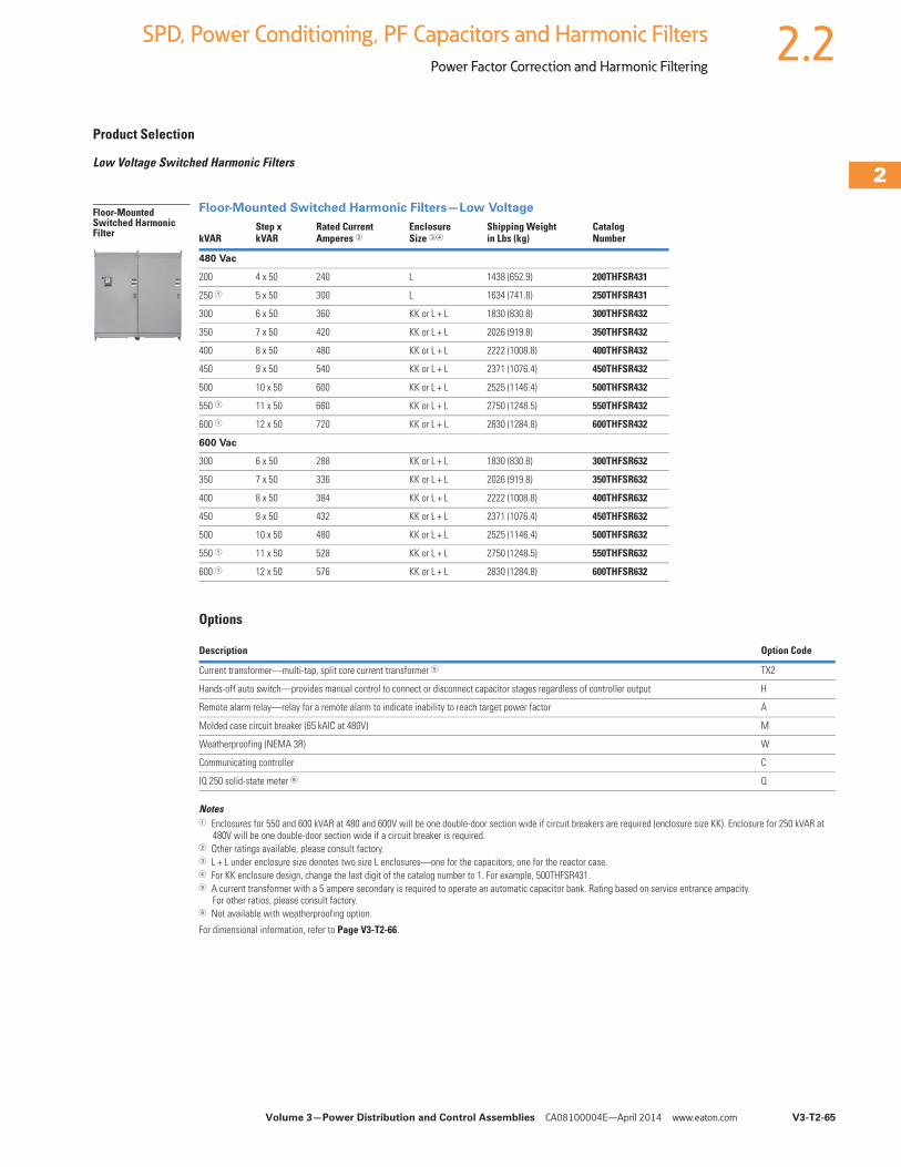
Volume 3—Power Distribution and Control Assemblies CA08100004E—April 2014 www.eaton.com V3-T2-65
2
2
2
2
2
2
2
2
2
2
2
2
2
2
2
2
2
2
2
2
2
2
2
2
2
2
2
2
2
2
2.2SPD, Power Conditioning, PF Capacitors and Harmonic Filters
Power Factor Correction and Harmonic Filtering
Product Selection
Low Voltage Switched Harmonic Filters
Floor-Mounted Switched Harmonic Filters—Low Voltage
Options
Notes1 Enclosures for 550 and 600 kVAR at 480 and 600V will be one double-door section wide if circuit breakers are required (enclosure size KK). Enclosure for 250 kVAR at
480V will be one double-door section wide if a circuit breaker is required.2 Other ratings available, please consult factory.3 L + L under enclosure size denotes two size L enclosures—one for the capacitors, one for the reactor case.4 For KK enclosure design, change the last digit of the catalog number to 1. For example, 500THFSR431.5 A current transformer with a 5 ampere secondary is required to operate an automatic capacitor bank. Rating based on service entrance ampacity.
For other ratios, please consult factory.6 Not available with weatherproofing option.
For dimensional information, refer to Page V3-T2-66.
kVAR Step xkVAR
Rated CurrentAmperes 2
EnclosureSize 34
Shipping Weightin Lbs (kg)
CatalogNumber
480 Vac
200 4 x 50 240 L 1438 (652.9) 200THFSR431
250 1 5 x 50 300 L 1634 (741.8) 250THFSR431
300 6 x 50 360 KK or L + L 1830 (830.8) 300THFSR432
350 7 x 50 420 KK or L + L 2026 (919.8) 350THFSR432
400 8 x 50 480 KK or L + L 2222 (1008.8) 400THFSR432
450 9 x 50 540 KK or L + L 2371 (1076.4) 450THFSR432
500 10 x 50 600 KK or L + L 2525 (1146.4) 500THFSR432
550 1 11 x 50 660 KK or L + L 2750 (1248.5) 550THFSR432
600 1 12 x 50 720 KK or L + L 2830 (1284.8) 600THFSR432
600 Vac
300 6 x 50 288 KK or L + L 1830 (830.8) 300THFSR632
350 7 x 50 336 KK or L + L 2026 (919.8) 350THFSR632
400 8 x 50 384 KK or L + L 2222 (1008.8) 400THFSR632
450 9 x 50 432 KK or L + L 2371 (1076.4) 450THFSR632
500 10 x 50 480 KK or L + L 2525 (1146.4) 500THFSR632
550 1 11 x 50 528 KK or L + L 2750 (1248.5) 550THFSR632
600 1 12 x 50 576 KK or L + L 2830 (1284.8) 600THFSR632
Description Option Code
Current transformer—multi-tap, split core current transformer 5 TX2
Hands-off auto switch—provides manual control to connect or disconnect capacitor stages regardless of controller output H
Remote alarm relay—relay for a remote alarm to indicate inability to reach target power factor A
Molded case circuit breaker (65 kAIC at 480V) M
Weatherproofing (NEMA 3R) W
Communicating controller C
IQ 250 solid-state meter 6 Q
Floor-Mounted Switched Harmonic Filter
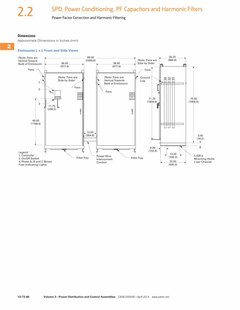
V3-T2-66 Volume 3—Power Distribution and Control Assemblies CA08100004E—April 2014 www.eaton.com
2
2
2
2
2
2
2
2
2
2
2
2
2
2
2
2
2
2
2
2
2
2
2
2
2
2
2
2
2
2
2.2 SPD, Power Conditioning, PF Capacitors and Harmonic Filters
Power Factor Correction and Harmonic Filtering
DimensionsApproximate Dimensions in Inches (mm)
Enclosures L + L Front and Side Views
46.00(1168.4)
11.75(298.5)
89.00(2260.6)
12.00(304.8)
3
2
1
PHASE CPHASE BPHASE A
38.50(977.9)
38.50(977.9)
DISCONNECTBEFORE SERVICING
HIGH VOLTAGE
CAUTION
DANGER
CAUTIONDISCONNECT
HIGH VOLTAGE
DANGER
BEFORE SERVICING
6.00(152.4)
25.00(635.0)
13.00(330.2)
3.00(76.2)
71.25(1809.8)
75.00(1905.0)
26.25(666.8)
(Note: Fans areVertical TowardBack of Enclosure)
(Note: Fans areVertical TowardsBack of Enclosure)
0.438 ø Mounting Holes2 per Channel
Power WireInterconnectConduit
(Note: Fans areSide by Side)
(Note: Fans areSide by Side)
GroundLug
Legend1. Controller2. On/Off Switch3. Phase A, B and C Blown Fuse Indicating Lights
Fans
Fans
Fans
Fans
Filter Tray Filter Tray
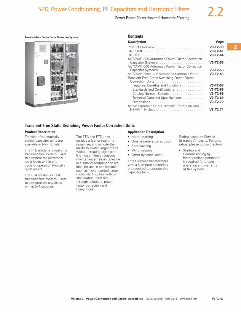
Volume 3—Power Distribution and Control Assemblies CA08100004E—April 2014 www.eaton.com V3-T2-67
2
2
2
2
2
2
2
2
2
2
2
2
2
2
2
2
2
2
2
2
2
2
2
2
2
2
2
2
2
2
2.2SPD, Power Conditioning, PF Capacitors and Harmonic Filters
Power Factor Correction and Harmonic Filtering
Transient-Free Power Factor Correction System ContentsDescription Page
Product Overview. . . . . . . . . . . . . . . . . . . . . . . . . . V3-T2-38
UNIPUMP. . . . . . . . . . . . . . . . . . . . . . . . . . . . . . . . V3-T2-41
UNIPAK. . . . . . . . . . . . . . . . . . . . . . . . . . . . . . . . . . V3-T2-44
AUTOVAR 300 Automatic Power Factor Correction Capacitor Systems . . . . . . . . . . . . . . . . . . . . . . . . V3-T2-55
AUTOVAR 600 Automatic Power Factor Correction Capacitor Systems . . . . . . . . . . . . . . . . . . . . . . . . V3-T2-58
AUTOVAR Filter—LV Automatic Harmonic Filter . . V3-T2-63
Transient-Free Static Switching Power Factor Correction Units . . . . . . . . . . . . . . . . . . . . . . . . . .
Features, Benefits and Functions . . . . . . . . . . . V3-T2-68
Standards and Certifications . . . . . . . . . . . . . . V3-T2-68
Catalog Number Selection . . . . . . . . . . . . . . . . V3-T2-69
Technical Data and Specifications . . . . . . . . . . V3-T2-69
Dimensions . . . . . . . . . . . . . . . . . . . . . . . . . . . V3-T2-70
Active-Harmonic Filter-Harmonic Correction Unit—NEMA 1 Enclosure . . . . . . . . . . . . . . . . . . . . . . . V3-T2-71
Transient-Free Static Switching Power Factor Correction UnitsProduct DescriptionTransient-free statically switch capacitor units are available in two models.
The FTE model is a real-time transient-free system, used to compensate extremely rapid loads within one cycle of operation (typically 5–20 msec).
The FTA model is a fast transient-free system, used to compensate any loads within 3–4 seconds.
The FTA and FTE units employ a fast or real-time response, and include the ability to switch larger steps without creating significant line noise. These relatively maintenance-free units reside in a smaller footprint and are ideal for use in applications such as flicker control, large motor starting, bus voltage stabilization, fault ride-through solutions, power factor correction and many more.
Application Description● Motor starting● On-site generation support● Spot welding● Wind turbines● Other dynamic loads
Three current transformers with a 5 ampere secondary are required to operate this capacitor bank.
Rating based on Service Entrance Ampacity. For other ratios, please consult factory.
● Startup and Commissioning by factory trained personnel is required for proper operation and warranty of this system
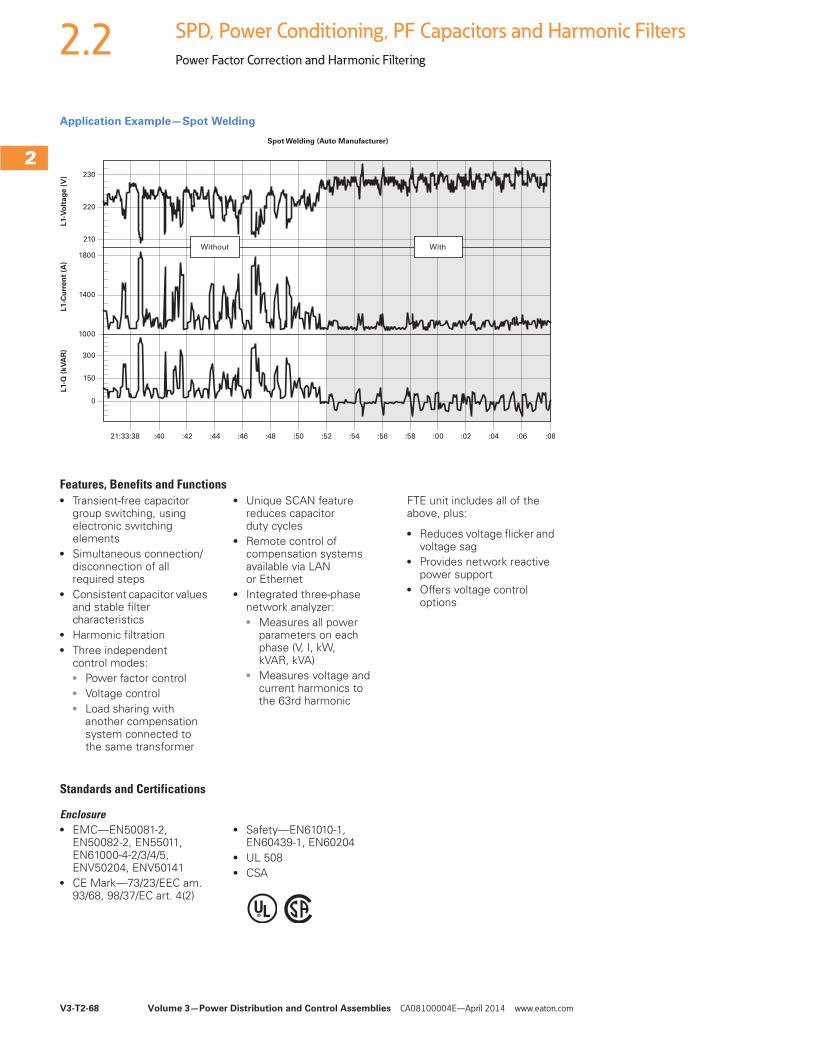
V3-T2-68 Volume 3—Power Distribution and Control Assemblies CA08100004E—April 2014 www.eaton.com
2
2
2
2
2
2
2
2
2
2
2
2
2
2
2
2
2
2
2
2
2
2
2
2
2
2
2
2
2
2
2.2 SPD, Power Conditioning, PF Capacitors and Harmonic Filters
Power Factor Correction and Harmonic Filtering
Application Example—Spot Welding
Features, Benefits and Functions● Transient-free capacitor
group switching, using electronic switching elements
● Simultaneous connection/disconnection of all required steps
● Consistent capacitor values and stable filter characteristics
● Harmonic filtration● Three independent
control modes:● Power factor control● Voltage control● Load sharing with
another compensation system connected to the same transformer
● Unique SCAN feature reduces capacitor duty cycles
● Remote control of compensation systems available via LAN or Ethernet
● Integrated three-phase network analyzer:● Measures all power
parameters on each phase (V, I, kW, kVAR, kVA)
● Measures voltage and current harmonics to the 63rd harmonic
FTE unit includes all of the above, plus:
● Reduces voltage flicker and voltage sag
● Provides network reactive power support
● Offers voltage control options
Standards and Certifications
Enclosure● EMC—EN50081-2,
EN50082-2, EN55011, EN61000-4-2/3/4/5, ENV50204, ENV50141
● CE Mark—73/23/EEC am. 93/68, 98/37/EC art. 4(2)
● Safety—EN61010-1, EN60439-1, EN60204
● UL 508● CSA
21:33:38
0
150
300
1000
1400
1800
210
220
230
L1-Q
(k
VA
R)
L1-C
urr
en
t (A
)L
1-V
olt
ag
e (
V)
Spot Welding (Auto Manufacturer)
:40 :42 :44 :46 :48 :50 :52 :54 :56 :58 :00 :02 :04 :06 :08
Without With
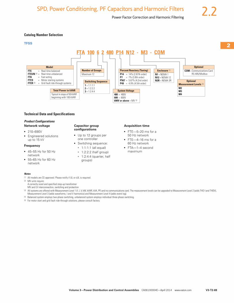
Volume 3—Power Distribution and Control Assemblies CA08100004E—April 2014 www.eaton.com V3-T2-69
2
2
2
2
2
2
2
2
2
2
2
2
2
2
2
2
2
2
2
2
2
2
2
2
2
2
2
2
2
2
2.2SPD, Power Conditioning, PF Capacitors and Harmonic Filters
Power Factor Correction and Harmonic Filtering
Catalog Number Selection
TFSS
Technical Data and Specifications
Product ConfigurationsNetwork voltage
● 210–690V● Engineered solutions
up to 15 kV
Frequency
● 45–55 Hz for 50 Hz network
● 55–65 Hz for 60 Hz network
Capacitor group configurations
● Up to 12 groups per one controller
● Switching sequence:● 1:1:1:1 (all equal)● 1:2:2:2 (half group)● 1:2:4:4 (quarter, half
groups)
Acquisition time
● FTE—5–20 ms for a 50 Hz network
● FTE—4–16 ms for a 60 Hz network
● FTA—1–4 second maximum
Notes1 All models are CE approved. Please notify if UL or cUL is required.2 MV units require:
A correctly sized and specified step-up transformer MV and LV interconnection, switching and protection
3 All systems are offered with Measurement Level 1 (f, I, V, kW, kVAR, kVA, PF) and no communications card. The measurement levels can be upgraded to Measurement Level 2 (adds THD I and THDV), Measurement Level 3 (adds waveforms, I and V harmonics) and Measurement Level 4 (adds event log).
4 Balanced system employs two-phase switching, unbalanced system employs individual three-phase switching.5 For motor start and grid fault ride-through solutions, please consult factory.
OptionalMeasurement Levels 3
M2M3M4
Enclosure 1
N1 = NEMA 1N12 = NEMA 12N3R = NEMA 3R
OptionalCOM = Communications Card
RS-485/ModbusPercent Reactory (Tuning)P14 = 14% (2.67th order)P7 = 7% (3.8th order)P567 = 5.67% (4.2nd order)P49 = 4.9% (4.5th order)
ModelFTE = Real-time balancedFTEUN 4 = Real-time unbalancedFTA = Fast actingFTES = Motor starting systemsFTER 5 = Grid fault ride-through systems
Total Power in kVARTypical in steps of 50 kVAR beginning with 100 kVAR
Number of GroupsMaximum 12
Switching Sequence1 = 1:1:1:12 = 1:2:2:23 = 1:2:4:4 System Voltage
480 = 480V600 = 600V690V or above = MV 2
FTA 100 6 2 480 P14 N12 - M3 - COM
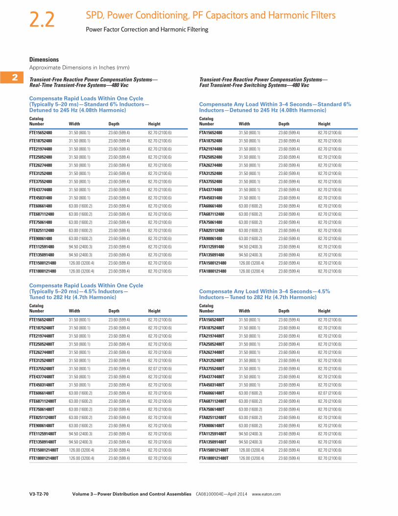
V3-T2-70 Volume 3—Power Distribution and Control Assemblies CA08100004E—April 2014 www.eaton.com
2
2
2
2
2
2
2
2
2
2
2
2
2
2
2
2
2
2
2
2
2
2
2
2
2
2
2
2
2
2
2.2 SPD, Power Conditioning, PF Capacitors and Harmonic Filters
Power Factor Correction and Harmonic Filtering
DimensionsApproximate Dimensions in Inches (mm)
Transient-Free Reactive Power Compensation Systems—Real-Time Transient-Free Systems—480 Vac
Compensate Rapid Loads Within One Cycle (Typically 5–20 ms)—Standard 6% Inductors—Detuned to 245 Hz (4.08th Harmonic)
Compensate Rapid Loads Within One Cycle (Typically 5–20 ms)—4.5% Inductors—Tuned to 282 Hz (4.7th Harmonic)
Transient-Free Reactive Power Compensation Systems—Fast Transient-Free Switching Systems—480 Vac
Compensate Any Load Within 3–4 Seconds—Standard 6% Inductors—Detuned to 245 Hz (4.08th Harmonic)
Compensate Any Load Within 3–4 Seconds—4.5% Inductors—Tuned to 282 Hz (4.7th Harmonic)
CatalogNumber Width Depth Height
FTE15652480 31.50 (800.1) 23.60 (599.4) 82.70 (2100.6)
FTE18752480 31.50 (800.1) 23.60 (599.4) 82.70 (2100.6)
FTE21974480 31.50 (800.1) 23.60 (599.4) 82.70 (2100.6)
FTE25052480 31.50 (800.1) 23.60 (599.4) 82.70 (2100.6)
FTE26274480 31.50 (800.1) 23.60 (599.4) 82.70 (2100.6)
FTE31252480 31.50 (800.1) 23.60 (599.4) 82.70 (2100.6)
FTE37552480 31.50 (800.1) 23.60 (599.4) 82.70 (2100.6)
FTE43774480 31.50 (800.1) 23.60 (599.4) 82.70 (2100.6)
FTE45031480 31.50 (800.1) 23.60 (599.4) 82.70 (2100.6)
FTE60661480 63.00 (1600.2) 23.60 (599.4) 82.70 (2100.6)
FTE687112480 63.00 (1600.2) 23.60 (599.4) 82.70 (2100.6)
FTE75061480 63.00 (1600.2) 23.60 (599.4) 82.70 (2100.6)
FTE825112480 63.00 (1600.2) 23.60 (599.4) 82.70 (2100.6)
FTE90061480 63.00 (1600.2) 23.60 (599.4) 82.70 (2100.6)
FTE112591480 94.50 (2400.3) 23.60 (599.4) 82.70 (2100.6)
FTE135091480 94.50 (2400.3) 23.60 (599.4) 82.70 (2100.6)
FTE1500121480 126.00 (3200.4) 23.60 (599.4) 82.70 (2100.6)
FTE1800121480 126.00 (3200.4) 23.60 (599.4) 82.70 (2100.6)
CatalogNumber Width Depth Height
FTE15652480T 31.50 (800.1) 23.60 (599.4) 82.70 (2100.6)
FTE18752480T 31.50 (800.1) 23.60 (599.4) 82.70 (2100.6)
FTE21974480T 31.50 (800.1) 23.60 (599.4) 82.70 (2100.6)
FTE25052480T 31.50 (800.1) 23.60 (599.4) 82.70 (2100.6)
FTE26274480T 31.50 (800.1) 23.60 (599.4) 82.70 (2100.6)
FTE31252480T 31.50 (800.1) 23.60 (599.4) 82.70 (2100.6)
FTE37552480T 31.50 (800.1) 23.60 (599.4) 82.07 (2100.6)
FTE43774480T 31.50 (800.1) 23.60 (599.4) 82.70 (2100.6)
FTE45031480T 31.50 (800.1) 23.60 (599.4) 82.70 (2100.6)
FTE60661480T 63.00 (1600.2) 23.60 (599.4) 82.70 (2100.6)
FTE687112480T 63.00 (1600.2) 23.60 (599.4) 82.70 (2100.6)
FTE75061480T 63.00 (1600.2) 23.60 (599.4) 82.70 (2100.6)
FTE825112480T 63.00 (1600.2) 23.60 (599.4) 82.70 (2100.6)
FTE90061480T 63.00 (1600.2) 23.60 (599.4) 82.70 (2100.6)
FTE112591480T 94.50 (2400.3) 23.60 (599.4) 82.70 (2100.6)
FTE135091480T 94.50 (2400.3) 23.60 (599.4) 82.70 (2100.6)
FTE1500121480T 126.00 (3200.4) 23.60 (599.4) 82.70 (2100.6)
FTE1800121480T 126.00 (3200.4) 23.60 (599.4) 82.70 (2100.6)
CatalogNumber Width Depth Height
FTA15652480 31.50 (800.1) 23.60 (599.4) 82.70 (2100.6)
FTA18752480 31.50 (800.1) 23.60 (599.4) 82.70 (2100.6)
FTA21974480 31.50 (800.1) 23.60 (599.4) 82.70 (2100.6)
FTA25052480 31.50 (800.1) 23.60 (599.4) 82.70 (2100.6)
FTA26274480 31.50 (800.1) 23.60 (599.4) 82.70 (2100.6)
FTA31252480 31.50 (800.1) 23.60 (599.4) 82.70 (2100.6)
FTA37552480 31.50 (800.1) 23.60 (599.4) 82.70 (2100.6)
FTA43774480 31.50 (800.1) 23.60 (599.4) 82.70 (2100.6)
FTA45031480 31.50 (800.1) 23.60 (599.4) 82.70 (2100.6)
FTA60661480 63.00 (1600.2) 23.60 (599.4) 82.70 (2100.6)
FTA687112480 63.00 (1600.2) 23.60 (599.4) 82.70 (2100.6)
FTA75061480 63.00 (1600.2) 23.60 (599.4) 82.70 (2100.6)
FTA825112480 63.00 (1600.2) 23.60 (599.4) 82.70 (2100.6)
FTA90061480 63.00 (1600.2) 23.60 (599.4) 82.70 (2100.6)
FTA112591480 94.50 (2400.3) 23.60 (599.4) 82.70 (2100.6)
FTA135091480 94.50 (2400.3) 23.60 (599.4) 82.70 (2100.6)
FTA1500121480 126.00 (3200.4) 23.60 (599.4) 82.70 (2100.6)
FTA1800121480 126.00 (3200.4) 23.60 (599.4) 82.70 (2100.6)
CatalogNumber Width Depth Height
FTA15652480T 31.50 (800.1) 23.60 (599.4) 82.70 (2100.6)
FTA18752480T 31.50 (800.1) 23.60 (599.4) 82.70 (2100.6)
FTA21974480T 31.50 (800.1) 23.60 (599.4) 82.70 (2100.6)
FTA25052480T 31.50 (800.1) 23.60 (599.4) 82.70 (2100.6)
FTA26274480T 31.50 (800.1) 23.60 (599.4) 82.70 (2100.6)
FTA31252480T 31.50 (800.1) 23.60 (599.4) 82.70 (2100.6)
FTA37552480T 31.50 (800.1) 23.60 (599.4) 82.70 (2100.6)
FTA43774480T 31.50 (800.1) 23.60 (599.4) 82.70 (2100.6)
FTA45031480T 31.50 (800.1) 23.60 (599.4) 82.70 (2100.6)
FTA60661480T 63.00 (1600.2) 23.60 (599.4) 82.07 (2100.6)
FTA687112480T 63.00 (1600.2) 23.60 (599.4) 82.70 (2100.6)
FTA75061480T 63.00 (1600.2) 23.60 (599.4) 82.70 (2100.6)
FTA825112480T 63.00 (1600.2) 23.60 (599.4) 82.70 (2100.6)
FTA90061480T 63.00 (1600.2) 23.60 (599.4) 82.70 (2100.6)
FTA112591480T 94.50 (2400.3) 23.60 (599.4) 82.70 (2100.6)
FTA135091480T 94.50 (2400.3) 23.60 (599.4) 82.70 (2100.6)
FTA1500121480T 126.00 (3200.4) 23.60 (599.4) 82.70 (2100.6)
FTA1800121480T 126.00 (3200.4) 23.60 (599.4) 82.70 (2100.6)
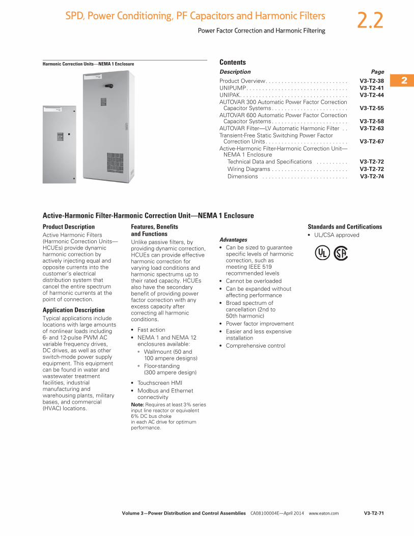
Volume 3—Power Distribution and Control Assemblies CA08100004E—April 2014 www.eaton.com V3-T2-71
2
2
2
2
2
2
2
2
2
2
2
2
2
2
2
2
2
2
2
2
2
2
2
2
2
2
2
2
2
2
2.2SPD, Power Conditioning, PF Capacitors and Harmonic Filters
Power Factor Correction and Harmonic Filtering
Harmonic Correction Units—NEMA 1 Enclosure ContentsDescription Page
Product Overview. . . . . . . . . . . . . . . . . . . . . . . . . . V3-T2-38
UNIPUMP. . . . . . . . . . . . . . . . . . . . . . . . . . . . . . . . V3-T2-41
UNIPAK. . . . . . . . . . . . . . . . . . . . . . . . . . . . . . . . . . V3-T2-44
AUTOVAR 300 Automatic Power Factor Correction Capacitor Systems . . . . . . . . . . . . . . . . . . . . . . . . V3-T2-55
AUTOVAR 600 Automatic Power Factor Correction Capacitor Systems . . . . . . . . . . . . . . . . . . . . . . . . V3-T2-58
AUTOVAR Filter—LV Automatic Harmonic Filter . . V3-T2-63
Transient-Free Static Switching Power Factor Correction Units . . . . . . . . . . . . . . . . . . . . . . . . . . V3-T2-67
Active-Harmonic Filter-Harmonic Correction Unit—NEMA 1 Enclosure
Technical Data and Specifications . . . . . . . . . . V3-T2-72
Wiring Diagrams . . . . . . . . . . . . . . . . . . . . . . . . V3-T2-72
Dimensions . . . . . . . . . . . . . . . . . . . . . . . . . . . V3-T2-74
Active-Harmonic Filter-Harmonic Correction Unit—NEMA 1 EnclosureProduct DescriptionActive Harmonic Filters (Harmonic Correction Units—HCUEs) provide dynamic harmonic correction by actively injecting equal and opposite currents into the customer’s electrical distribution system that cancel the entire spectrum of harmonic currents at the point of connection.
Application DescriptionTypical applications include locations with large amounts of nonlinear loads including 6- and 12-pulse PWM AC variable frequency drives, DC drives, as well as other switch-mode power supply equipment. This equipment can be found in water and wastewater treatment facilities, industrial manufacturing and warehousing plants, military bases, and commercial (HVAC) locations.
Features, Benefits and FunctionsUnlike passive filters, by providing dynamic correction, HCUEs can provide effective harmonic correction for varying load conditions and harmonic spectrums up to their rated capacity. HCUEs also have the secondary benefit of providing power factor correction with any excess capacity after correcting all harmonic conditions.
● Fast action● NEMA 1 and NEMA 12
enclosures available:● Wallmount (50 and
100 ampere designs)● Floor-standing
(300 ampere design)
● Touchscreen HMI● Modbus and Ethernet
connectivityNote: Requires at least 3% series input line reactor or equivalent 6% DC bus choke in each AC drive for optimum performance.
Advantages● Can be sized to guarantee
specific levels of harmonic correction, such as meeting IEEE 519 recommended levels
● Cannot be overloaded● Can be expanded without
affecting performance● Broad spectrum of
cancellation (2nd to 50th harmonic)
● Power factor improvement● Easier and less expensive
installation● Comprehensive control
Standards and Certifications● UL/CSA approved
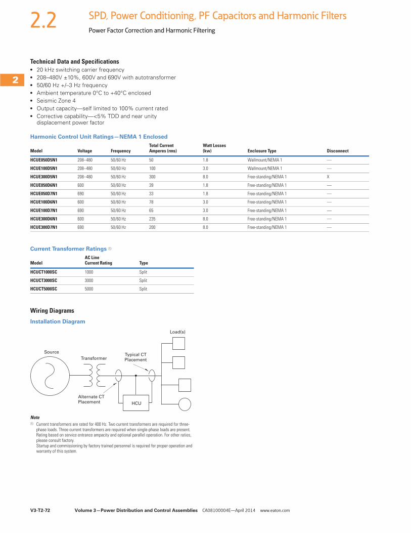
V3-T2-72 Volume 3—Power Distribution and Control Assemblies CA08100004E—April 2014 www.eaton.com
2
2
2
2
2
2
2
2
2
2
2
2
2
2
2
2
2
2
2
2
2
2
2
2
2
2
2
2
2
2
2.2 SPD, Power Conditioning, PF Capacitors and Harmonic Filters
Power Factor Correction and Harmonic Filtering
Technical Data and Specifications● 20 kHz switching carrier frequency● 208–480V ±10%, 600V and 690V with autotransformer● 50/60 Hz +/–3 Hz frequency● Ambient temperature 0°C to +40°C enclosed● Seismic Zone 4● Output capacity—self limited to 100% current rated● Corrective capability—<5% TDD and near unity
displacement power factor
Harmonic Control Unit Ratings—NEMA 1 Enclosed
Current Transformer Ratings 1
Wiring Diagrams
Installation Diagram
Note1 Current transformers are rated for 400 Hz. Two current transformers are required for three-
phase loads. Three current transformers are required when single-phase loads are present.Rating based on service entrance ampacity and optional parallel operation. For other ratios, please consult factory.Startup and commissioning by factory trained personnel is required for proper operation and warranty of this system.
Model Voltage FrequencyTotal CurrentAmperes (rms)
Watt Losses(kw) Enclosure Type Disconnect
HCUE050D5N1 208–480 50/60 Hz 50 1.8 Wallmount/NEMA 1 —
HCUE100D5N1 208–480 50/60 Hz 100 3.0 Wallmount/NEMA 1 —
HCUE300D5N1 208–480 50/60 Hz 300 8.0 Free-standing/NEMA 1 X
HCUE050D6N1 600 50/60 Hz 39 1.8 Free-standing/NEMA 1 —
HCUE050D7N1 690 50/60 Hz 33 1.8 Free-standing/NEMA 1 —
HCUE100D6N1 600 50/60 Hz 78 3.0 Free-standing/NEMA 1 —
HCUE100D7N1 690 50/60 Hz 65 3.0 Free-standing/NEMA 1 —
HCUE300D6N1 600 50/60 Hz 235 8.0 Free-standing/NEMA 1 —
HCUE300D7N1 690 50/60 Hz 200 8.0 Free-standing/NEMA 1 —
ModelAC LineCurrent Rating Type
HCUCT1000SC 1000 Split
HCUCT3000SC 3000 Split
HCUCT5000SC 5000 Split
Source
Transformer
Alternate CTPlacement
Typical CTPlacement
HCU
Load(s)
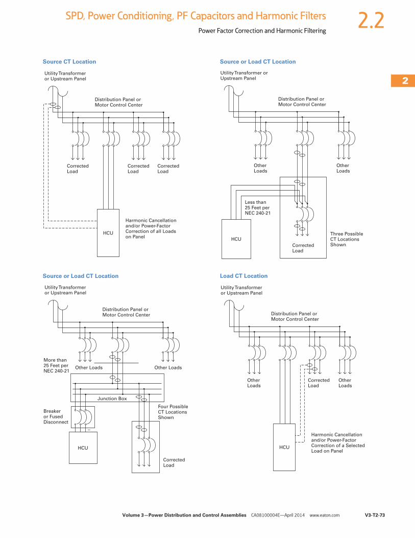
Volume 3—Power Distribution and Control Assemblies CA08100004E—April 2014 www.eaton.com V3-T2-73
2
2
2
2
2
2
2
2
2
2
2
2
2
2
2
2
2
2
2
2
2
2
2
2
2
2
2
2
2
2
2.2SPD, Power Conditioning, PF Capacitors and Harmonic Filters
Power Factor Correction and Harmonic Filtering
Source CT Location
Source or Load CT Location
Source or Load CT Location
Load CT Location
Utility Transformer or Upstream Panel
Distribution Panel or Motor Control Center
CorrectedLoad
HCU
Harmonic Cancellationand/or Power-FactorCorrection of all Loadson Panel
CorrectedLoad
CorrectedLoad
Utility Transformer or Upstream Panel
Distribution Panel or Motor Control Center
Other Loads Other Loads
More than 25 Feet per NEC 240-21
HCU
CorrectedLoad
Four PossibleCT LocationsShown
Breaker or FusedDisconnect
Junction Box
–
Utility Transformer orUpstream Panel
Distribution Panel or Motor Control Center
OtherLoads
OtherLoads
Less than 25 Feet per NEC 240-21
HCU
CorrectedLoad
Three PossibleCT LocationsShown
Utility Transformer or Upstream Panel
Distribution Panel or Motor Control Center
OtherLoads
HCU
Harmonic Cancellationand/or Power-FactorCorrection of a SelectedLoad on Panel
CorrectedLoad
OtherLoads
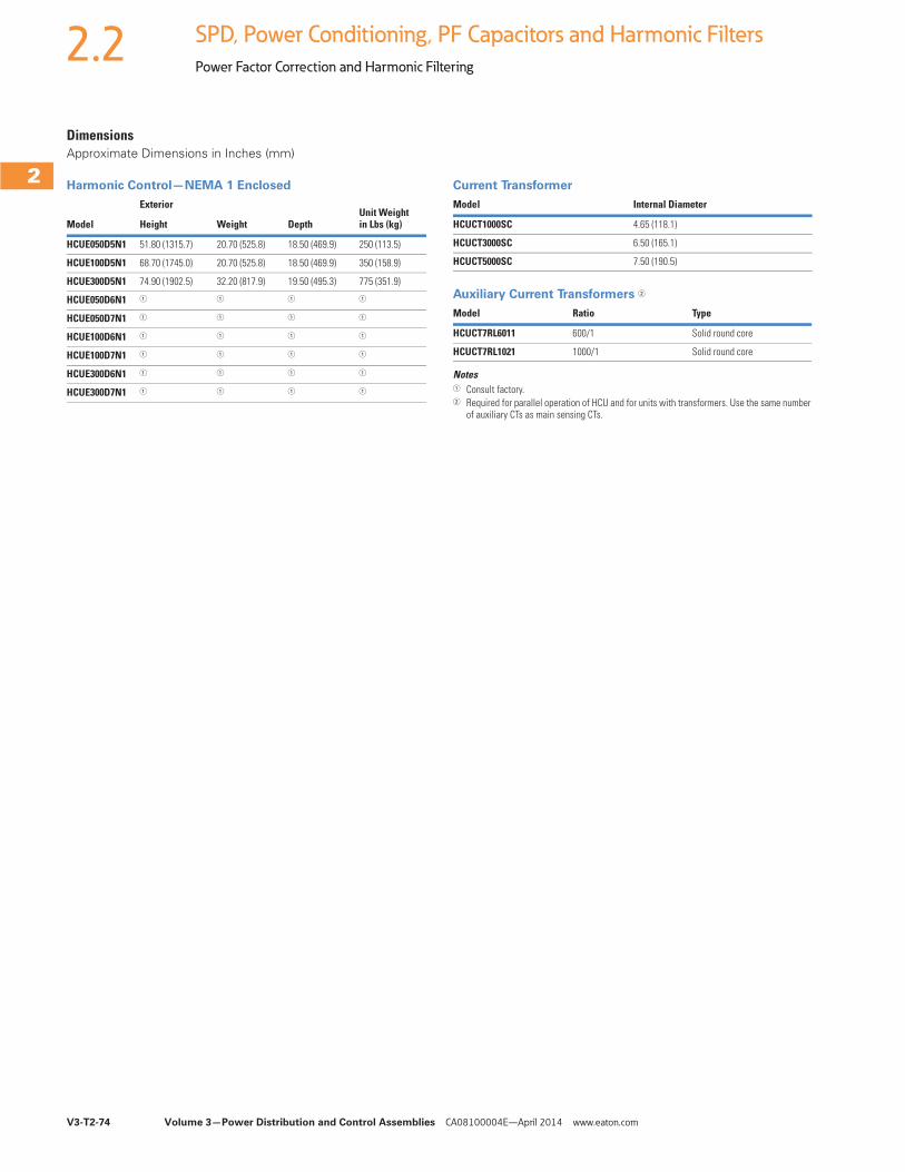
V3-T2-74 Volume 3—Power Distribution and Control Assemblies CA08100004E—April 2014 www.eaton.com
2
2
2
2
2
2
2
2
2
2
2
2
2
2
2
2
2
2
2
2
2
2
2
2
2
2
2
2
2
2
2.2 SPD, Power Conditioning, PF Capacitors and Harmonic Filters
Power Factor Correction and Harmonic Filtering
DimensionsApproximate Dimensions in Inches (mm)
Harmonic Control—NEMA 1 Enclosed Current Transformer
Auxiliary Current Transformers 2
Notes1 Consult factory.2 Required for parallel operation of HCU and for units with transformers. Use the same number
of auxiliary CTs as main sensing CTs.
Model
ExteriorUnit Weightin Lbs (kg)Height Weight Depth
HCUE050D5N1 51.80 (1315.7) 20.70 (525.8) 18.50 (469.9) 250 (113.5)
HCUE100D5N1 68.70 (1745.0) 20.70 (525.8) 18.50 (469.9) 350 (158.9)
HCUE300D5N1 74.90 (1902.5) 32.20 (817.9) 19.50 (495.3) 775 (351.9)
HCUE050D6N1 1 1 1 1
HCUE050D7N1 1 1 1 1
HCUE100D6N1 1 1 1 1
HCUE100D7N1 1 1 1 1
HCUE300D6N1 1 1 1 1
HCUE300D7N1 1 1 1 1
Model Internal Diameter
HCUCT1000SC 4.65 (118.1)
HCUCT3000SC 6.50 (165.1)
HCUCT5000SC 7.50 (190.5)
Model Ratio Type
HCUCT7RL6011 600/1 Solid round core
HCUCT7RL1021 1000/1 Solid round core
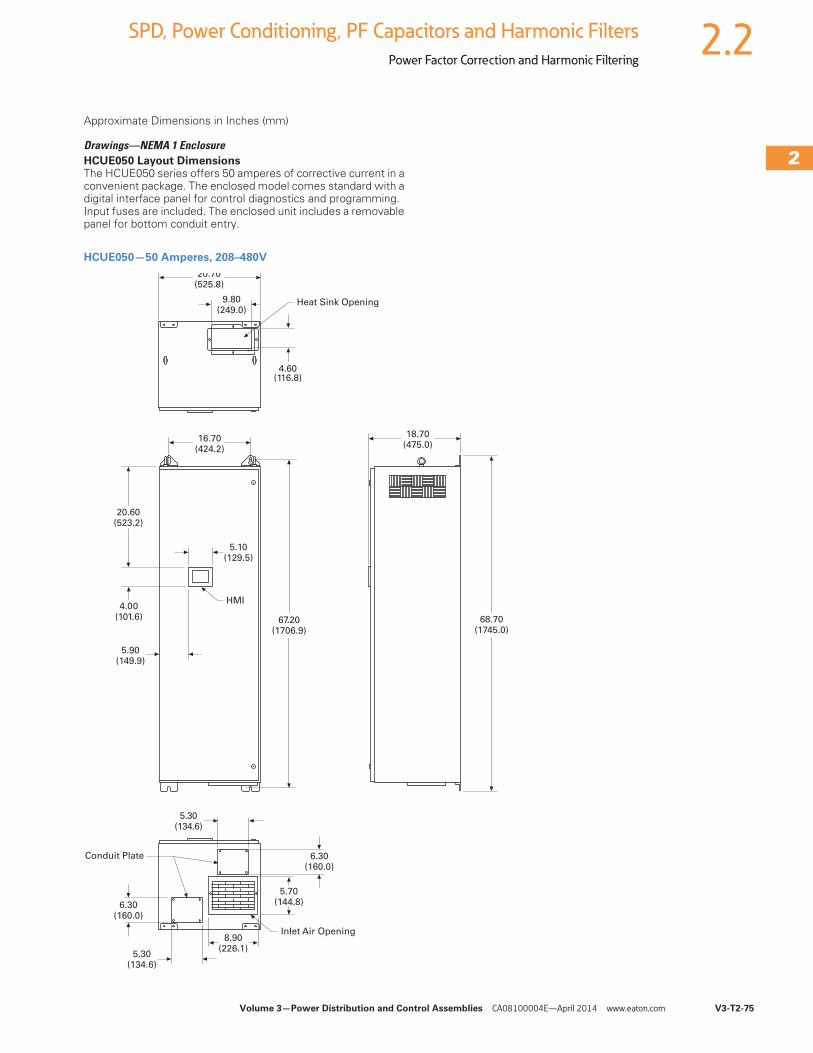
Volume 3—Power Distribution and Control Assemblies CA08100004E—April 2014 www.eaton.com V3-T2-75
2
2
2
2
2
2
2
2
2
2
2
2
2
2
2
2
2
2
2
2
2
2
2
2
2
2
2
2
2
2
2.2SPD, Power Conditioning, PF Capacitors and Harmonic Filters
Power Factor Correction and Harmonic Filtering
Approximate Dimensions in Inches (mm)
Drawings—NEMA 1 EnclosureHCUE050 Layout DimensionsThe HCUE050 series offers 50 amperes of corrective current in a convenient package. The enclosed model comes standard with a digital interface panel for control diagnostics and programming. Input fuses are included. The enclosed unit includes a removable panel for bottom conduit entry.
HCUE050—50 Amperes, 208–480V
20.70(525.8)
Heat Sink Opening
4.60(116.8)
9.80(249.0)
16.70(424.2)
HMI4.00
(101.6)
5.10(129.5)
20.60(523.2)
67.20(1706.9)
18.70(475.0)
68.70(1745.0)
Inlet Air Opening
6.30(160.0)
5.30(134.6)
6.30(160.0)
5.30(134.6)
5.70(144.8)
8.90(226.1)
Conduit Plate
5.90(149.9)
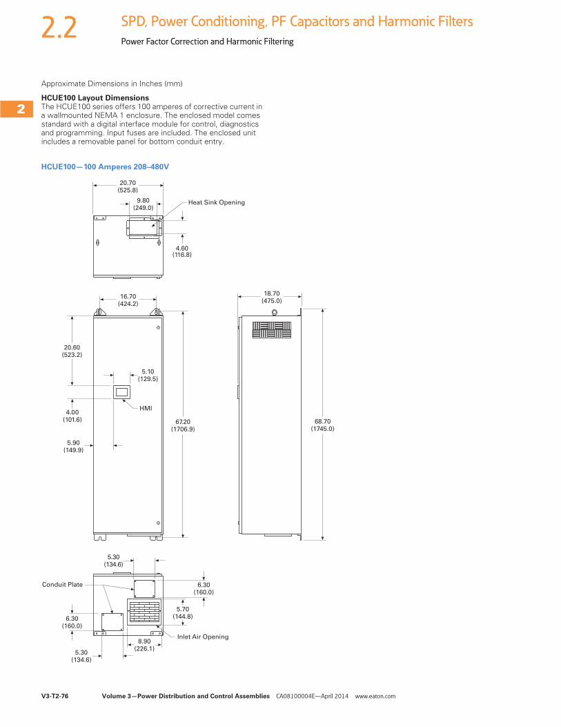
V3-T2-76 Volume 3—Power Distribution and Control Assemblies CA08100004E—April 2014 www.eaton.com
2
2
2
2
2
2
2
2
2
2
2
2
2
2
2
2
2
2
2
2
2
2
2
2
2
2
2
2
2
2
2.2 SPD, Power Conditioning, PF Capacitors and Harmonic Filters
Power Factor Correction and Harmonic Filtering
Approximate Dimensions in Inches (mm)
HCUE100 Layout DimensionsThe HCUE100 series offers 100 amperes of corrective current in a wallmounted NEMA 1 enclosure. The enclosed model comes standard with a digital interface module for control, diagnostics and programming. Input fuses are included. The enclosed unit includes a removable panel for bottom conduit entry.
HCUE100—100 Amperes 208–480V
20.70(525.8)
Heat Sink Opening
4.60(116.8)
9.80(249.0)
16.70(424.2)
HMI4.00
(101.6)
5.10(129.5)
20.60(523.2)
67.20(1706.9)
18.70(475.0)
68.70(1745.0)
Inlet Air Opening
6.30(160.0)
5.30(134.6)
6.30(160.0)
5.30(134.6)
5.70(144.8)
8.90(226.1)
Conduit Plate
5.90(149.9)
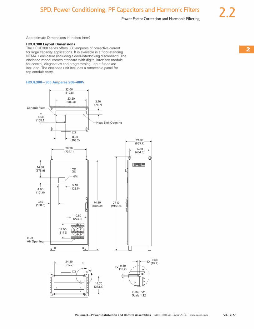
Volume 3—Power Distribution and Control Assemblies CA08100004E—April 2014 www.eaton.com V3-T2-77
2
2
2
2
2
2
2
2
2
2
2
2
2
2
2
2
2
2
2
2
2
2
2
2
2
2
2
2
2
2
2.2SPD, Power Conditioning, PF Capacitors and Harmonic Filters
Power Factor Correction and Harmonic Filtering
Approximate Dimensions in Inches (mm)
HCUE300 Layout DimensionsThe HCUE300 series offers 300 amperes of corrective current for large capacity applications. It is available in a floor-standing NEMA 1 enclosure (including a door-interlocking disconnect). The enclosed model comes standard with digital interface module for control, diagnostics and programming. Input fuses are included. The enclosed unit includes a removable panel for top conduit entry.
HCUE300—300 Amperes 208–480V
32.00(812.8)
Heat Sink Opening
6.50(165.1)
23.20(589.3)
28.90(734.1)
HMI
4.00(101.6)
5.10(129.5)
14.80(375.9)
74.80(1899.9)
17.10(434.3)
77.10(1958.3)
InletAir Opening
10.80(274.3)
12.50(317.5)
14.70(373.4)
7.40(188.0)
8.00(203.2)
Conduit Plate
3.10(78.7)
”A“
24.30(617.2)
Detail ”A“Scale 1:12
4X 0.40 (10.2)
4X 0.60 (15.2)
21.80(553.7)
Related Documents