Spatial Information Spatial Information Systems (SIS) Systems (SIS) COMP 30110 COMP 30110 Spatial data structures (1) Spatial data structures (1)

Spatial Information Systems (SIS) COMP 30110 Spatial data structures (1)
Dec 14, 2015
Welcome message from author
This document is posted to help you gain knowledge. Please leave a comment to let me know what you think about it! Share it to your friends and learn new things together.
Transcript

Spatial Information Systems (SIS)Spatial Information Systems (SIS)
COMP 30110COMP 30110
Spatial data structures (1)Spatial data structures (1)
Spatial data structuresSpatial data structures
Data structures that have been defined for manipulating sets Data structures that have been defined for manipulating sets of spatial entitiesof spatial entities
Two aspects:Two aspects:
– storing: space occupied? redundancies?storing: space occupied? redundancies?
– querying, analysing, updating, etc.: time required?querying, analysing, updating, etc.: time required?
In general, it is important to be able to manipulate efficiently, In general, it is important to be able to manipulate efficiently, still maintaining a “low” space complexitystill maintaining a “low” space complexity
Requirement: the stored information must allow for an Requirement: the stored information must allow for an unambiguousunambiguous representation of the subdivision representation of the subdivision

Spatial data structures: evaluationSpatial data structures: evaluation
Spatial data structures can be evaluated in terms of:Spatial data structures can be evaluated in terms of:
– space complexityspace complexity: amount of space (memory) needed for : amount of space (memory) needed for storing storing all information (entities and relations) that is explicitly all information (entities and relations) that is explicitly representedrepresented
– time complexitytime complexity of the algorithms for calculating relations of the algorithms for calculating relations that that are not explicitly representedare not explicitly represented

Constant and variable relationsConstant and variable relations
In a generic plane subdivision, a relation is:In a generic plane subdivision, a relation is:
- - constantconstant if it involves a constant number of entities if it involves a constant number of entities
(e.g.: EV, EE, EF involve two entities each)(e.g.: EV, EE, EF involve two entities each)
- - variablevariable if it involves a variable number of entities if it involves a variable number of entities
(e.g.: VV, VE, VF, FV, FE, FF involve a different number of entities (e.g.: VV, VE, VF, FV, FE, FF involve a different number of entities depending on the different cases)depending on the different cases)
Pjj
Pii
e
fjj
fiieii ejj
f f4
f3
f2
f1P1P2
P3 P4
e1
e2
e3
e4
P1P2
P3
P e1e2
e3f1
f2
f3
Topology/ConnectivityTopology/Connectivity
•Generic sets of entities: any possible topological relationsGeneric sets of entities: any possible topological relations
• Overlayed sets of entities (plane subdivisions): only Overlayed sets of entities (plane subdivisions): only meetmeet and and disjointdisjoint
•MeetMeet: topological relation that defines : topological relation that defines connectivityconnectivity between entities in a plane subdivisionbetween entities in a plane subdivision
•Entities of different dimension are “connected” in Entities of different dimension are “connected” in different ways: relations (vertex-, edge-, face-based) seen different ways: relations (vertex-, edge-, face-based) seen beforebefore

Spaghetti data structureSpaghetti data structure
• Spaghetti data structureSpaghetti data structure: represents sets of points, : represents sets of points, lines and polygonslines and polygons
• Can be used for both generic sets of entities and Can be used for both generic sets of entities and overlayed sets (plane subdivisions)overlayed sets (plane subdivisions)
• The geometry of any spatial entity is described The geometry of any spatial entity is described independently of other entitiesindependently of other entities
• No topology/connectivity information is recordedNo topology/connectivity information is recorded

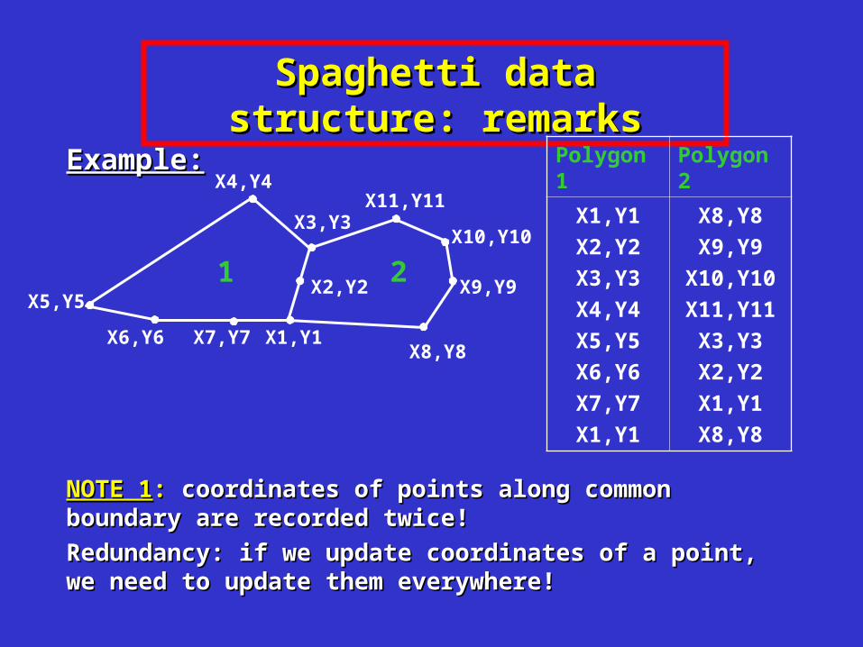
Spaghetti data structure: exampleSpaghetti data structure: example
Example:Example: points, lines and polygons are stored separately points, lines and polygons are stored separately
Polygon 1 Polygon 2
X1,Y1
X2,Y2
X3,Y3
X4,Y4
X5,Y5
X6,Y6
X7,Y7
X1,Y1
X8,Y8
X9,Y9
X10,Y10
X11,Y11
X3,Y3
X2,Y2
X1,Y1
X8,Y8
1 2X5,Y5
X4,Y4
X3,Y3X11,Y11
X1,Y1
X2,Y2
X7,Y7X6,Y6
X10,Y10
X9,Y9
X8,Y8
For each polygon, we store a (ordered) list of coordinates of points on its For each polygon, we store a (ordered) list of coordinates of points on its boundary (this is not the same as FV relation!)boundary (this is not the same as FV relation!)

Another data structureAnother data structure
Polygon 1
Polygon 2
P1
P2
P3
P4
P5
P6
P7
P1
P8
P9
P10
P11
P3
P2
P1
P8
1 2P5
P4
P3P11
P1
P2
P7P6
P10
P9
P8
Points and polygons are related: Points and polygons are related: for each polygon, we store a for each polygon, we store a (ordered) list of (ordered) list of pointspoints (not (not coordinates) on its coordinates) on its boundary: boundary: FV relationFV relation
ID Coord.
P1
P2
P3
P4
P5
P6
P7
P8
P9
P10
P11
X1,Y1
X2,Y2
X3,Y3
X4,Y4
X5,Y5
X6,Y6
X7,Y7
X8,Y8
X9,Y9
X10,Y10
X11,Y11
Spaghetti data structure: pros & consSpaghetti data structure: pros & cons
•Advantages: Advantages:
– simplicitysimplicity
– easy insertions of new entities (all entities are independent)easy insertions of new entities (all entities are independent)
•Cons: Cons:
– inefficient for topological queriesinefficient for topological queries
– redundancies (and consequently, possible inconsistencies!)redundancies (and consequently, possible inconsistencies!)
Spaghetti data structure: remarksSpaghetti data structure: remarks
Example:Example:
NOTE 1NOTE 1:: coordinates of points along common boundary are recorded coordinates of points along common boundary are recorded twice!twice!
Redundancy: if we update coordinates of a point, we need to update Redundancy: if we update coordinates of a point, we need to update them everywhere!them everywhere!
Polygon 1 Polygon 2
X1,Y1
X2,Y2
X3,Y3
X4,Y4
X5,Y5
X6,Y6
X7,Y7
X1,Y1
X8,Y8
X9,Y9
X10,Y10
X11,Y11
X3,Y3
X2,Y2
X1,Y1
X8,Y8
1 2X5,Y5
X4,Y4
X3,Y3X11,Y11
X1,Y1
X2,Y2
X7,Y7X6,Y6
X10,Y10
X9,Y9
X8,Y8
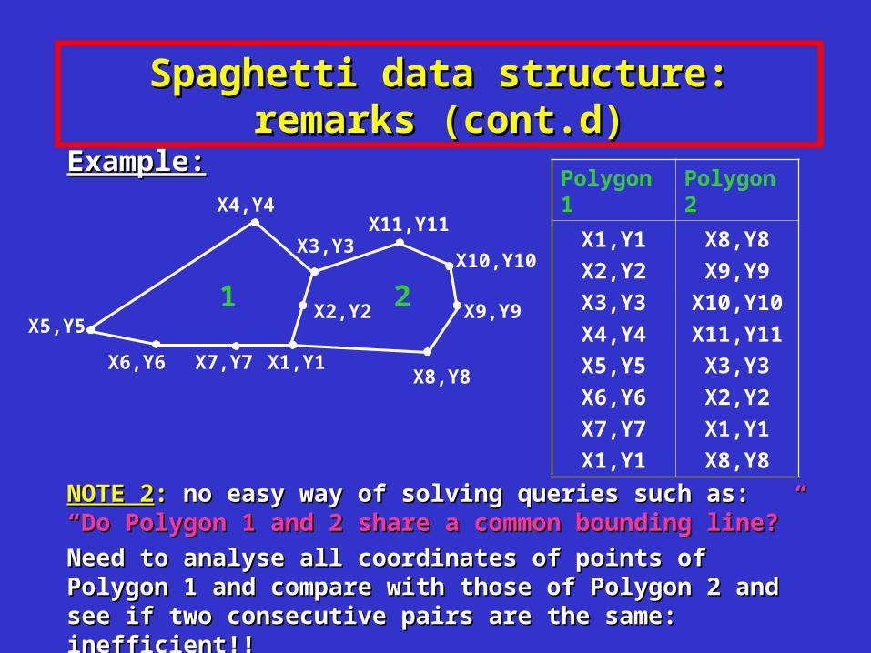
Spaghetti data structure: remarks (cont.d)Spaghetti data structure: remarks (cont.d)
Example:Example:
NOTE 2NOTE 2:: no easy way of solving queries such as: no easy way of solving queries such as: “Do Polygon 1 and 2 “Do Polygon 1 and 2 share a common bounding line?”share a common bounding line?”
Need to analyse all coordinates of points of Polygon 1 and compare Need to analyse all coordinates of points of Polygon 1 and compare with those of Polygon 2 and see if two consecutive pairs are the same: with those of Polygon 2 and see if two consecutive pairs are the same: inefficient!!inefficient!!
Polygon 1 Polygon 2
X1,Y1
X2,Y2
X3,Y3
X4,Y4
X5,Y5
X6,Y6
X7,Y7
X1,Y1
X8,Y8
X9,Y9
X10,Y10
X11,Y11
X3,Y3
X2,Y2
X1,Y1
X8,Y8
1 2X5,Y5
X4,Y4
X3,Y3X11,Y11
X1,Y1
X2,Y2
X7,Y7X6,Y6
X10,Y10
X9,Y9
X8,Y8

Topological data structures for plane subdivisionsTopological data structures for plane subdivisions
• Incorporate “connectivity” among spatial objects by Incorporate “connectivity” among spatial objects by storing explicitly a subset of the relations seen beforestoring explicitly a subset of the relations seen before
• Two types of points: Two types of points: – points that are endpoints of a line (vertices)points that are endpoints of a line (vertices)
– points that define the shape (geometry) of a linepoints that define the shape (geometry) of a line
• For polygons/lines: For polygons/lines: – adjacency information (e.g., encode polygons on each side of a adjacency information (e.g., encode polygons on each side of a boundary line – left and right polygon with respect to the boundary line – left and right polygon with respect to the direction of the line: EF relation)direction of the line: EF relation)

Topological data structures: motivationsTopological data structures: motivations
Storing connectivity information explicitly allows for more Storing connectivity information explicitly allows for more efficient spatial queriesefficient spatial queries
ExampleExample: :
if we store relation if we store relation FEFE explicitely (i.e., for each polygon we explicitely (i.e., for each polygon we
store a list of IDs of edges bounding it), the query:store a list of IDs of edges bounding it), the query:
““do Polygon 1 and 2 share a common bounding line?”do Polygon 1 and 2 share a common bounding line?”
only requires checking whether the two lists contain any common IDsonly requires checking whether the two lists contain any common IDs
Polygon 1
Polygon 2
e1
e2
e3
e4
e5
e6
e7
e8
e9
e10
e11
e12
e2
e1
1 2e4
e3 e11
e7
e1
e6e5
e10
e9
e8
e2
e12

Topological data structures: motivations Topological data structures: motivations (cont.d)(cont.d)
Topology/connectivity: important criterion to establish the Topology/connectivity: important criterion to establish the correctness (integrity, consistency) of geographic databasescorrectness (integrity, consistency) of geographic databases
ExamplesExamples::
– neighbouring countries must share a boundaryneighbouring countries must share a boundary
– seas and lakes cannot overlapseas and lakes cannot overlap

Doubly-Connected Edge List (DCEL) structureDoubly-Connected Edge List (DCEL) structure
(Preparata and Shamos, 1985)(Preparata and Shamos, 1985)
• DCELDCEL structure stores: structure stores:– the three sets of entities V, E, Fthe three sets of entities V, E, F
– the three edge-based relations EV, EE, EF (all constant)the three edge-based relations EV, EE, EF (all constant)
– the two partial relations: FE* and VE* the two partial relations: FE* and VE*
FE*FE*: : associates a face associates a face f f with with one of one of
the edges bounding the edges bounding ff
VE*VE*: : associates a vertex associates a vertex v v with onewith one
of the edges incident in of the edges incident in vvV F
EEF
FE**EV
VE**
EE

Example (1)Example (1)
P9
P8
P3
f1 f2e4
e3 e11
e7
e1
e6e5
e10
e9
e8
e2
e12
P5
P4P11
P1
P2
P7P6
P10f0
Entities
V {P1,P2,….., P11}
E {e1, e2,….., e12}
F {f0,f1,f2}
Partial relations
VE* FE*
P1 e1 f0 e3
P2 e2 f1 e3
P3 e3 f2 e1
P4 e4
P5 e5
P6 e6
P7 e7
P8 e8
P9 e9
P10 e10
P11 e11
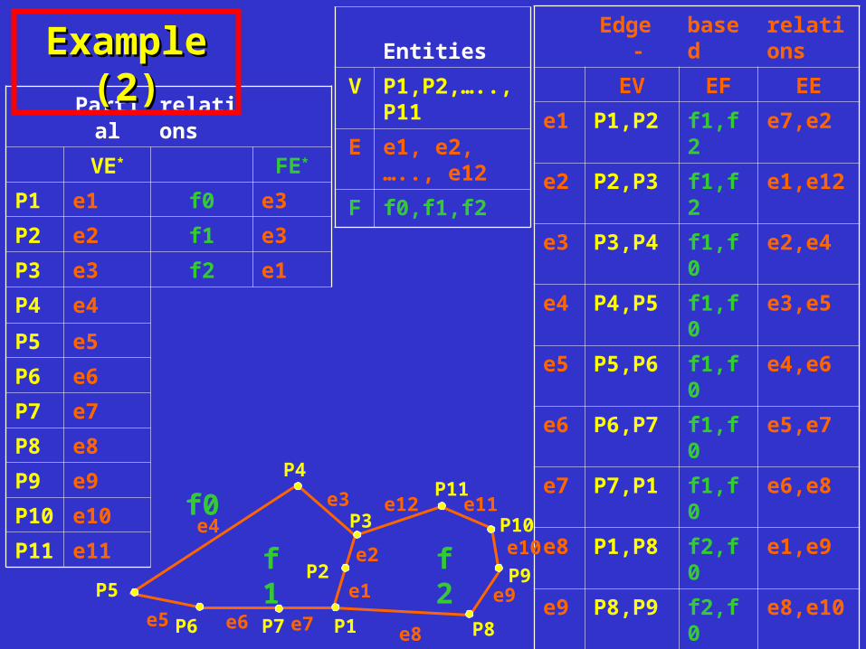
Example (2)Example (2) Entities
V P1,P2,….., P11
E e1, e2,….., e12
F f0,f1,f2
Edge - based relations
EV EF EE
e1 P1,P2 f1,f2 e7,e2
e2 P2,P3 f1,f2 e1,e12
e3 P3,P4 f1,f0 e2,e4
e4 P4,P5 f1,f0 e3,e5
e5 P5,P6 f1,f0 e4,e6
e6 P6,P7 f1,f0 e5,e7
e7 P7,P1 f1,f0 e6,e8
e8 P1,P8 f2,f0 e1,e9
e9 P8,P9 f2,f0 e8,e10
e10 P9,P10 f2,f0 e9,e11
e11 P10,P11 f2,f0 e10,e12
e12 P11,P3 f2,f0 e11,e3
P9
P8
P3
f1 f2e4
e3 e11
e7
e1
e6e5
e10
e9
e8
e2
e12
P5
P4P11
P1
P2
P7P6
P10f0
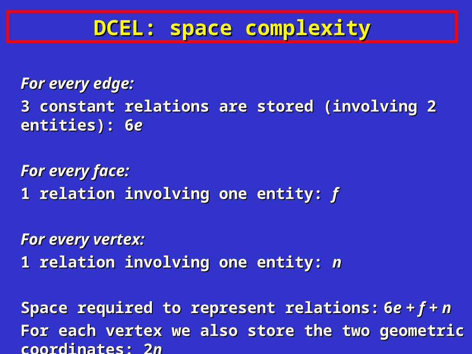
DCEL: space complexityDCEL: space complexity
For every edge:For every edge:
3 constant relations are stored (involving 2 entities): 63 constant relations are stored (involving 2 entities): 6ee
For every face:For every face:
1 relation involving one entity: 1 relation involving one entity: ff
For every vertex:For every vertex:
1 relation involving one entity: 1 relation involving one entity: nn
Space required to represent relations:Space required to represent relations: 66e + f + ne + f + n
For each vertex we also store the two geometric coordinates: 2For each vertex we also store the two geometric coordinates: 2nn

Retrieving missing relations: FERetrieving missing relations: FE
Calculating complete relation FE:Calculating complete relation FE: Obtained by combining FE Obtained by combining FE* * and and EEEE
For example, given a face For example, given a face f1f1, we find the first bounding edge , we find the first bounding edge e3e3 using FEusing FE**. Then using EE we find the successor . Then using EE we find the successor e4e4 ofof e3e3 (in (in counter-closkwise order) on the boundary ofcounter-closkwise order) on the boundary of f1: f1: if if e3e3 is oriented in is oriented in such a way that such a way that f1f1 is on its left hand side, then is on its left hand side, then e4e4 is the second of is the second of the two edges associated with the two edges associated with e3e3 through EEthrough EE
P9
P8
P3
f1 f2e4
e3 e11
e7
e1
e6e5
e10
e9
e8
e2
e12
P5
P4P11
P1
P2
P7P6
P10f0

Retrieving missing relations: FE (cont.d)Retrieving missing relations: FE (cont.d)
We apply the same method (2We apply the same method (2ndnd element of EE) to obtain all other element of EE) to obtain all other edges on the boundary of edges on the boundary of f1f1, until we reach , until we reach e3e3 again. again.
P9
P8
P3
f1 f2e4
e3 e11
e7
e1
e6e5
e10
e9
e8
e2
e12
P5
P4P11
P1
P2
P7P6
P10f0

DCEL: FV and FFDCEL: FV and FF
FV can be obtained by combining FE and EV: for each bounding FV can be obtained by combining FE and EV: for each bounding edge edge ee of a given face of a given face f f (obtained with FE), we consider its (obtained with FE), we consider its endpoints using EVendpoints using EV
FF can be obtained by combining FE and EF: for each bounding FF can be obtained by combining FE and EF: for each bounding edge edge ee of a given face of a given face f f (obtained with FE), we consider the other (obtained with FE), we consider the other face face f’ f’ obtained by using EFobtained by using EF

DCEL: VE, VV, VFDCEL: VE, VV, VF
Exercise!!Exercise!!
For next weekFor next week
Related Documents