page 1 of 9 TECHNICAL GUIDANCE SPANDREL PANELS TO COLD ROOFS 7.2 /25 January 2018 (First Issue) NHBC NHBC House, Davy Avenue, Knowlhill, Milton Keynes, Bucks MK5 8FP Tel: 0344 633 1000 Fax: 01908 747 255 www.nhbc.co.uk QUESTION ANSWER Spandrel panels are generally factory-made, transported to site in one or more sections, and craned into position on to timber framed or masonry support walls. Panel framing is usually formed from vertical studs at 600mm centres, with head and soleplates. Typical timber sizes are: 89 x 38mm or 97 x 47mm with nailed connections or 72 x 47mm where joints are plated, as in trussed rafter plated joints. Spandrel panels should be designed by the manufacturer in accordance with the building designer’s details and requirements and manufactured in accordance with guidance from the Structural Timber Association (www.structuraltimber.co.uk) or Trussed Rafter Association (www.tra.org.uk). The top of party wall panels should be slightly lower than the level of adjacent trusses, to allow the trusses to deflect on application of the roof tiles, without causing hogging of the tiles over the panel. Gable panels are installed level with the top of the trusses with flush roof verges; or to underside of gable ladders with boxed verges. Party wall panels require tying back into the roof structure on BOTH sides, so that they remain in place in the event of the roof on one side burning away. Gable spandrel panels must resist wind loads acting on the gable end walls and any loads from applied cladding, e.g. tile hanging. These loads are transmitted through the panel to the roof structure via lateral restraints. In accordance with masonry codes, wall ties to masonry cladding should be increased in number at the top of a wall. Wall ties should also be increased at potential slip planes, e.g. horizontal cavity tray locations. Detail 10 below shows where wall tie frequency should be increased. Any impervious weather protection, e.g. polythene sheeting, should be removed once the roof is watertight, sufficient to allow the panel to breathe, identify stud positions for fixing restraints, and checking for any damage during erection. Breathable protective membrane may require removal for inspection if there are signs of trapped moisture or damage to the panel. Where membranes are retained, e.g. on gable panels, the position of the studs should be marked on the membrane for fixing of wall ties. Which factors should be taken into account when designing and installing spandrel panels over party walls and gable walls with cold roof voids? 1) GENERAL CONSIDERATIONS 2) LATERAL RESTRAINT 3) FIRE STOPPING Spandrel panels require lateral restraint at rafter level and along the base of the panel. Tall panels may also require lateral restraint in line with any intermediate longitudinal bracing to the roof trusses. Lateral restraint can be provided by: - timber members (e.g. the longitudinal bracing secured to the spandrel with timber ledgers/noggings), fixed into at least two studs within the panels, - metal restraint straps fixed to the panel and to noggings, or timber bracing fixed between or across the trusses. Multiple fixings into narrow studs, e.g. 38mm wide, at the end of restraint straps, should be avoided by fixing the straps into timber ledgers, fixed across and into two studs within the panel - see below. Fire stopping is required between the top of the party wall spandrel panel and the roof covering, and between the spandrel and the masonry supporting wall. This is typically achieved with flexible rock fibre mineral quilt. The fire stopping should extend into any boxed eaves in the form of fire-resisting board or wired rock fibre quilt, screwed or nailed in place (see diagram in NHBC Standards clasue 7.2.16).

Welcome message from author
This document is posted to help you gain knowledge. Please leave a comment to let me know what you think about it! Share it to your friends and learn new things together.
Transcript

CURTAIN WALLING FORMED FROMSTACKED WINDOW ARRANGEMENTS EXXON –
page 1 of 9
MARKING OF SAFETY GLASS XXXX – 2015
TECHNICAL GUIDANCESPANDREL PANELS TO COLD ROOFS 7.2 /25 January 2018 (First Issue)
NHBC NHBC House, Davy Avenue, Knowlhill, Milton Keynes, Bucks MK5 8FPTel: 0344 633 1000 Fax: 01908 747 255 www.nhbc.co.uk
QUESTION
ANSWER
Spandrel panels are generally factory-made, transported to site in one or more sections, and craned into position on to timber framed or masonry support walls. Panel framing is usually formed from vertical studs at 600mm centres, with head and soleplates. Typical timber sizes are:
89 x 38mm or 97 x 47mm with nailed connections or72 x 47mm where joints are plated, as in trussed rafter plated joints.
Spandrel panels should be designed by the manufacturer in accordance with the building designer’s details and requirements and manufactured in accordance with guidance from the Structural Timber Association (www.structuraltimber.co.uk) or Trussed Rafter Association (www.tra.org.uk).
The top of party wall panels should be slightly lower than the level of adjacent trusses, to allow the trusses to de�ect on application of the roof tiles, without causing hogging of the tiles over the panel. Gable panels are installed level with the top of the trusses with �ush roof verges; or to underside of gable ladders with boxed verges.
Party wall panels require tying back into the roof structure on BOTH sides, so that they remain in place in the event of the roof on one side burning away. Gable spandrel panels must resist wind loads acting on the gable end walls and any loads from applied cladding, e.g. tile hanging. These loads are transmitted through the panel to the roof structure via lateral restraints. In accordance with masonry codes, wall ties to masonry cladding should be increased in number at the top of a wall. Wall ties should also be increased at potential slip planes, e.g. horizontal cavity tray locations. Detail 10 below shows where wall tie frequency should be increased.
Any impervious weather protection, e.g. polythene sheeting, should be removed once the roof is watertight, su�cient to allow the panel to breathe, identify stud positions for �xing restraints, and checking for any damage during erection. Breathable protective membrane may require removal for inspection if there are signs of trapped moisture or damage to the panel. Where membranes are retained, e.g. on gable panels, the position of the studs should be marked on the membrane for �xing of wall ties.
Which factors should be taken into account when designing and installing spandrel panels over party walls and gable walls with cold roof voids?
1) GENERAL CONSIDERATIONS
2) LATERAL RESTRAINT
3) FIRE STOPPING
Spandrel panels require lateral restraint at rafter level and along the base of the panel. Tall panels may also require lateral restraint in line with any intermediate longitudinal bracing to the roof trusses. Lateral restraint can be provided by:
- timber members (e.g. the longitudinal bracing secured to the spandrel with timber ledgers/noggings), �xed into at least two studs within the panels, - metal restraint straps �xed to the panel and to noggings, or timber bracing �xed between or across the trusses. Multiple �xings into narrow studs, e.g. 38mm wide, at the end of restraint straps, should be avoided by �xing the straps into timber ledgers, �xed across and into two studs within the panel - see below.
Fire stopping is required between the top of the party wall spandrel panel and the roof covering, and between the spandrel and the masonry supporting wall. This is typically achieved with �exible rock �bre mineral quilt. The �re stopping should extend into any boxed eaves in the form of �re-resisting board or wired rock �bre quilt, screwed ornailed in place (see diagram in NHBC Standards clasue 7.2.16).
6.1/25 – 2015 – 20147.2/25 – Jan 2018TECHNICAL GUIDANCE
page 2 of 9
NHBC NHBC House, Davy Avenue, Knowlhill, Milton Keynes, Bucks MK5 8FPTel: 0344 633 1000 Fax: 01908 747 255 www.nhbc.co.uk
The building designer/architect should agree �re protection requirements with the NHBC building control surveyor for the project (or local authority building control in Scotland and Northern Ireland), particularly for panels clad with weatherboarding or tile hanging, where lack of �re resistance to external face can be a�ected by �re spread from below. Requirements should be clearly illustrated on the working drawings.
Generally party wall spandrel panels should provide 60 minutes �re protection, which can be achieved with two layers of 12.5mm plasterboard on both sides of the framing. Plasterboard joints in each layer and between layers should be made over a stud or nogging and staggered. With twin leaf spandrel panels the same �re protection is applied to one side of each leaf, usually the side facing the roof void.
Alternatively, single layer board drylining may be used if supported by suitable test reports to show compliance with the �re and sound requirements.
Fire protection to gable end spandrel panels is dependent on the dwelling type, e.g. house or �at, its height, and distance from relevant boundaries. Based on Approved Document B1 (England) and 100mm thick masonry tied to the gable spandrel panel, the following �re protection generally applies:
i) Three storey houses and two storey �ats.External spread of �re (Requirement B4) may apply if the building is close to a boundary and the area of the gable wall is larger than the ‘allowable unprotected area’ for the plot. Where a 30 minute period of �re resistance is needed, an unlined spandrel panel with 100mm masonry wall is considered to meet this requirement.
ii) Houses and �ats with height exceeding (i) above.External spread of �re (Requirement B4) may apply if the building is close to a boundary and the area of the gable wall is larger than the ‘unprotected area’. A 60 minute period of �re resistance is needed. An unlined spandrel panel and 100mm masonry wall is NOT considered su�cient to meet this period. Consideration should be given to �re protection of the spandrel panel, such as a lining to the internal face of the panel.
Panel-to-panel butt joints should maintain the required �re protection. This can be achieved by covering the joint with strips of plasterboard to the same thickness as used on the main panel - see detail below. Other panel to panel jointing methods may be accepted if supported by an appropriate �re test report. Jointing methods which rely on the use of intumescent sealants are di�cult to inspect for correct installation, so should generally be avoided.
4) FIRE PROTECTION
5) ACOUSTICS
6) TYPES OF SPANDREL PANELS AND WORKED EXAMPLES
The spandrel panel should meet the sound insulation requirements set out in the National Building Regulations.One way of achieving this is to follow the guidance in Robust Details; the guidance in this document follows that approach. Designs which do not adopt Robust Details will require sound testing on completion.
The types of spandrel panel covered by this guidance are as follows:
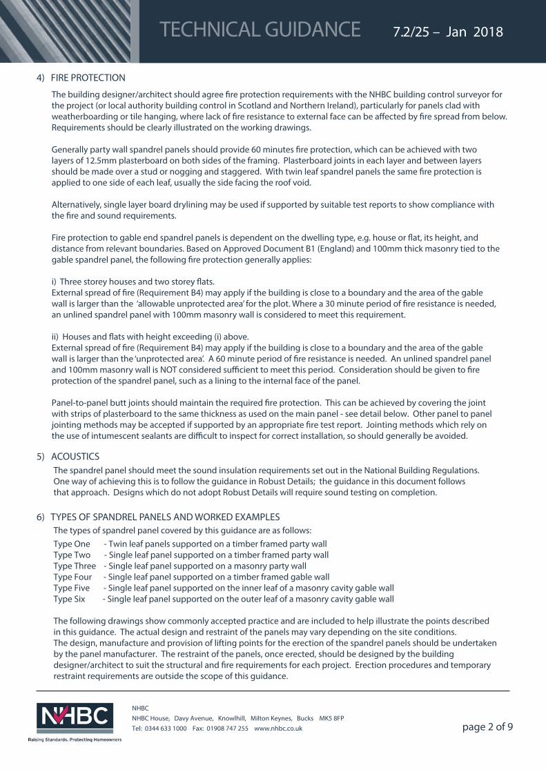
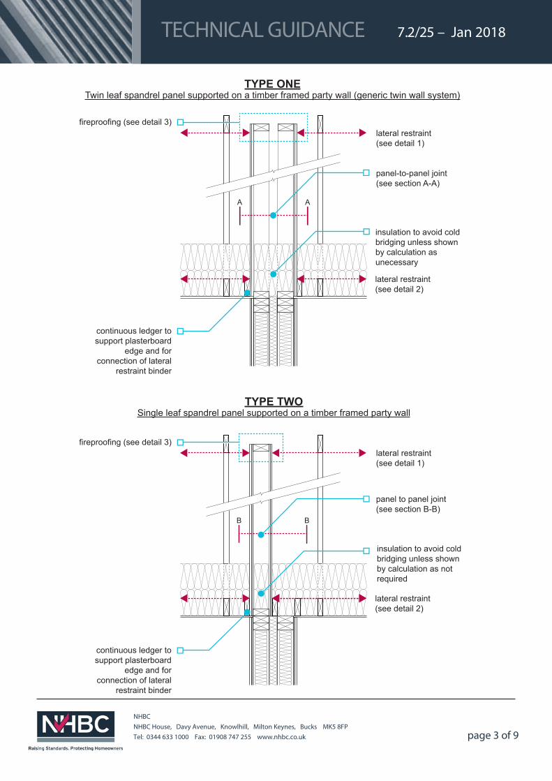
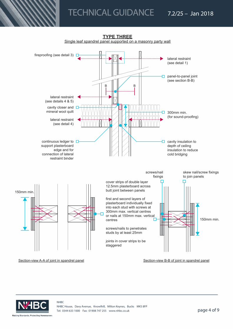
Type One - Twin leaf panels supported on a timber framed party wall Type Two - Single leaf panel supported on a timber framed party wall Type Three - Single leaf panel supported on a masonry party wall Type Four - Single leaf panel supported on a timber framed gable wallType Five - Single leaf panel supported on the inner leaf of a masonry cavity gable wall Type Six - Single leaf panel supported on the outer leaf of a masonry cavity gable wall
The following drawings show commonly accepted practice and are included to help illustrate the points described in this guidance. The actual design and restraint of the panels may vary depending on the site conditions.The design, manufacture and provision of lifting points for the erection of the spandrel panels should be undertaken by the panel manufacturer. The restraint of the panels, once erected, should be designed by the building designer/architect to suit the structural and �re requirements for each project. Erection procedures and temporary restraint requirements are outside the scope of this guidance.
6.1/25 – 2015 – 20147.2/25 – Jan 2018 TECHNICAL GUIDANCE
page 3 of 9
NHBC NHBC House, Davy Avenue, Knowlhill, Milton Keynes, Bucks MK5 8FPTel: 0344 633 1000 Fax: 01908 747 255 www.nhbc.co.uk
continuous ledger to support plasterboard
edge and for connection of lateral
restraint binder
lateral restraint (see detail 1)
lateral restraint (see detail 2)
B B
fireproofing (see detail 3)
Single leaf spandrel panel supported on a timber framed party wallTYPE TWO
panel to panel joint (see section B-B)
insulation to avoid cold bridging unless shownby calculation as not required
insulation to avoid cold bridging unless shownby calculation as unecessary
continuous ledger to support plasterboard
edge and for connection of lateral
restraint binder
fireproofing (see detail 3)lateral restraint (see detail 1)
lateral restraint (see detail 2)
Twin leaf spandrel panel supported on a timber framed party wall (generic twin wall system)TYPE ONE
A A
panel-to-panel joint (see section A-A)
6.1/25 – 2015 XXX – 20147.2/25 – Jan 2018 TECHNICAL GUIDANCE
page 4 of 9
NHBC NHBC House, Davy Avenue, Knowlhill, Milton Keynes, Bucks MK5 8FPTel: 0344 633 1000 Fax: 01908 747 255 www.nhbc.co.uk
continuous ledger to support plasterboard
edge and for connection of lateral
restraint binder
lateral restraint (see detail 1)
lateral restraint (see detail 4)
B B
lateral restraint (see details 4 & 5)
300mm min.(for sound-proofing)
cavity insulation to depth of ceiling insulation to reduce cold bridging
cavity closer and mineral wool quilt
fireproofing (see detail 3)
panel-to-panel joint (see section B-B)
Single leaf spandrel panel supported on a masonry party wallTYPE THREE
Section-view A-A of joint in spandrel panel
cover strips of double layer 12.5mm plasterboard across butt joint between panels
first and second layers of plasterboard individually fixed into each stud with screws at 300mm max. vertical centres or nails at 150mm max. vertical centres
screws/nails to penetrates studs by at least 25mm
joints in cover strips to be staggered
150mm min.
Section-view B-B of joint in spandrel panel
screws/nail fixings
skew nail/screw fixings to join panels
150mm min.
Single leaf spandrel panel supported on a timber framed gable wallTYPE FOUR
TYPE SIX
6.1/25 – 2015 – 20147.2/25 – Jan 2018 TECHNICAL GUIDANCE
Page 5 of 9
NHBC NHBC House, Davy Avenue, Knowlhill, Milton Keynes, Bucks MK5 8FPTel: 0344 633 1000 Fax: 01908 747 255 www.nhbc.co.uk
wall tie arrangement(see detail 10)
lateral restraint (see detail 7)
lateral restraint (see detail 6)
Single leaf spandrel panel supported on a timber framed gable wallTYPE FOUR
wall tie arrangement(see detail 10)
lateral restraint (see detail 8)
lateral restraint (see detail 6)
cavity insulation(see detail 9)Wall tie arrangement(see detail 10)
lateral restraint (see detail 8)
Single leaf spandrel panel supported on the inner leaf of a masonry cavity gable wall
TYPE FIVE
lateral restraint (see detail 8)
lateral restraint (see detail 8)
lateral restraint (see detail 6) provide drained and vented
cavity between cladding and breather membrane over sheathing board
dpc
Single leaf spandrel panel supported on the outer leaf of a masonry cavity gable wall
TYPE SIX
6.1/25 – 2015 – 20147.2/25 – Jan 2018 TECHNICAL GUIDANCE
page 6 of 9
NHBC NHBC House, Davy Avenue, Knowlhill, Milton Keynes, Bucks MK5 8FPTel: 0344 633 1000 Fax: 01908 747 255 www.nhbc.co.uk
TYPE FIVE
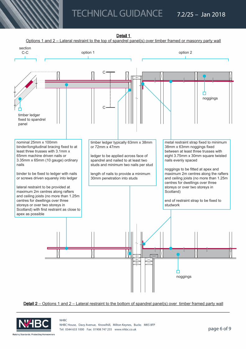
option 1 option 2section
C-C
timber ledger fixed to spandrel panel
C
C
noggings
nominal 25mm x 100mm binder/longitudinal bracing fixed to at least three trusses with 3.1mm x 65mm machine driven nails or 3.35mm x 65mm (10 gauge) ordinary nails
binder to be fixed to ledger with nails or screws driven squarely into ledger
lateral restraint to be provided at maximum 2m centres along rafters and ceiling joists (no more than 1.25m centres for dwellings over three storeys or over two storeys in Scotland) with first restraint as close to apex as possible
timber ledger typically 63mm x 38mmor 72mm x 47mm
ledger to be applied across face of spandrel and nailed to at least two studs and minimum two nails per stud
length of nails to provide a minimum 30mm penetration into studs
metal restraint strap fixed to minimum 38mm x 63mm noggings fixed between at least three trusses with eight 3.75mm x 30mm square twisted nails evenly spaced
noggings to be fitted at apex and maximum 2m centres along the rafters and ceiling joists (no more than 1.25m centres for dwellings over three storeys or over two storeys in Scotland)
end of restraint strap to be fixed to studwork
Detail 1 Options 1 and 2 – Lateral restraint to the top of spandrel panel(s) over timber framed or masonry party wall
noggings
Detail 2 – Options 1 and 2 – Lateral restraint to the bottom of spandrel panel(s) over timber framed party wall
6.1/25 – 2015 – 20147.2/25 – Jan 2018 TECHNICAL GUIDANCE
page 7 of 9
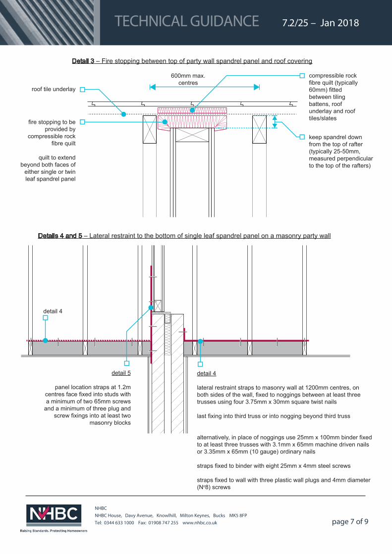
NHBC NHBC House, Davy Avenue, Knowlhill, Milton Keynes, Bucks MK5 8FPTel: 0344 633 1000 Fax: 01908 747 255 www.nhbc.co.uk
roof tile underlay
compressible rock fibre quilt (typically 60mm) fitted between tiling battens, roof underlay and roof tiles/slatesfire stopping to be
provided by compressible rock
fibre quilt
quilt to extend beyond both faces of
either single or twin leaf spandrel panel
keep spandrel down from the top of rafter (typically 25-50mm, measured perpendicular to the top of the rafters)
Detail 3 – Fire stopping between top of party wall spandrel panel and roof covering
detail 5
panel location straps at 1.2m centres face fixed into studs with a minimum of two 65mm screws
and a minimum of three plug and screw fixings into at least two
masonry blocks
detail 4
lateral restraint straps to masonry wall at 1200mm centres, on both sides of the wall, fixed to noggings between at least three trusses using four 3.75mm x 30mm square twist nails
last fixing into third truss or into nogging beyond third truss
alternatively, in place of noggings use 25mm x 100mm binder fixed to at least three trusses with 3.1mm x 65mm machine driven nails or 3.35mm x 65mm (10 gauge) ordinary nails
straps fixed to binder with eight 25mm x 4mm steel screws
straps fixed to wall with three plastic wall plugs and 4mm diameter (No8) screws
Details 4 and 5 – Lateral restraint to the bottom of single leaf spandrel panel on a masonry party wall
detail 4
600mm max.centres
6.1/25 – 2015 – 20147.2/25 – Jan 2018 TECHNICAL GUIDANCE
page 8 of 9
NHBC NHBC House, Davy Avenue, Knowlhill, Milton Keynes, Bucks MK5 8FPTel: 0344 633 1000 Fax: 01908 747 255 www.nhbc.co.uk
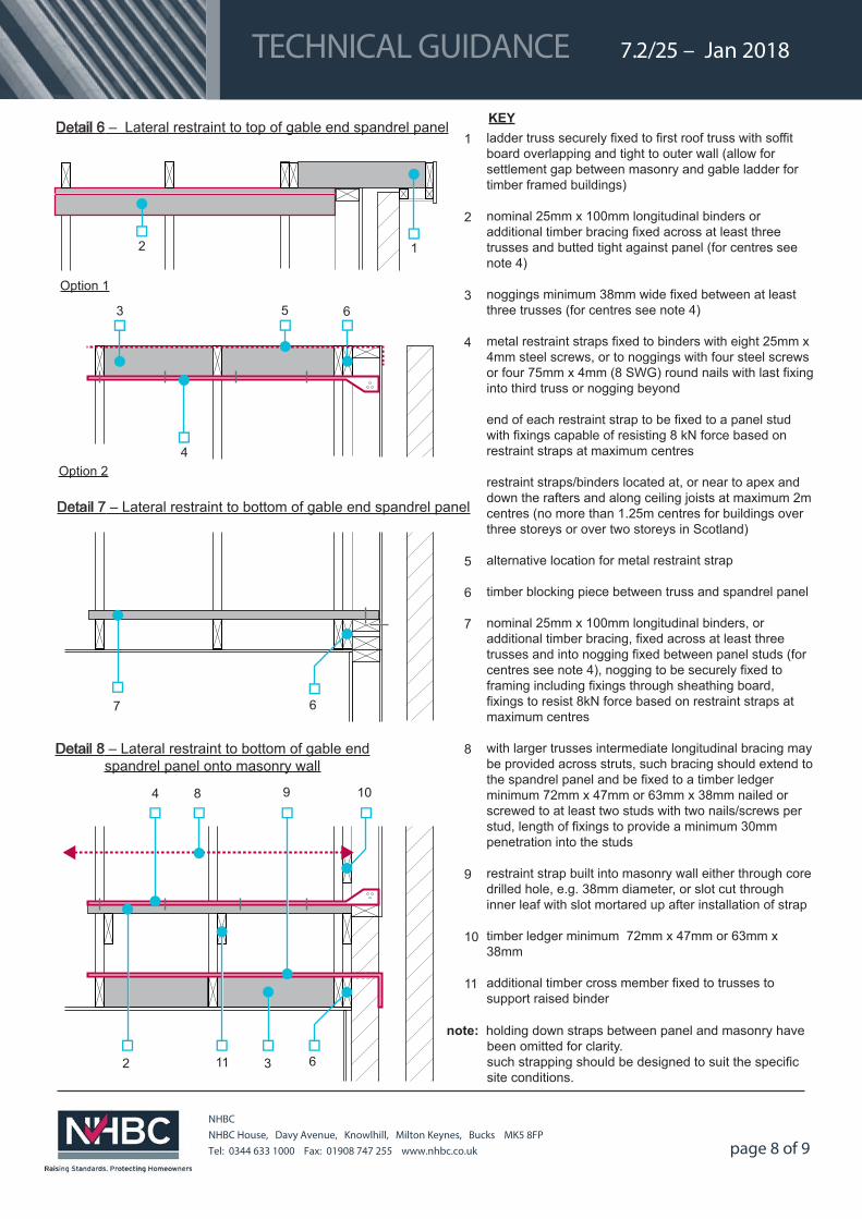
Detail 6 – Lateral restraint to top of gable end spandrel panel
3
7 6
Detail 7 – Lateral restraint to bottom of gable end spandrel panel
Detail 8 – Lateral restraint to bottom of gable end spandrel panel onto masonry wall
11
4
3
8 9 10
62
ladder truss securely fixed to first roof truss with soffit board overlapping and tight to outer wall (allow for settlement gap between masonry and gable ladder for timber framed buildings)
nominal 25mm x 100mm longitudinal binders or additional timber bracing fixed across at least three trusses and butted tight against panel (for centres see note 4)
noggings minimum 38mm wide fixed between at least three trusses (for centres see note 4)
metal restraint straps fixed to binders with eight 25mm x 4mm steel screws, or to noggings with four steel screws or four 75mm x 4mm (8 SWG) round nails with last fixing into third truss or nogging beyond
end of each restraint strap to be fixed to a panel stud with fixings capable of resisting 8 kN force based on restraint straps at maximum centres
restraint straps/binders located at, or near to apex and down the rafters and along ceiling joists at maximum 2m centres (no more than 1.25m centres for buildings over three storeys or over two storeys in Scotland)
alternative location for metal restraint strap
timber blocking piece between truss and spandrel panel
nominal 25mm x 100mm longitudinal binders, or additional timber bracing, fixed across at least three trusses and into nogging fixed between panel studs (for centres see note 4), nogging to be securely fixed to framing including fixings through sheathing board, fixings to resist 8kN force based on restraint straps at maximum centres
with larger trusses intermediate longitudinal bracing may be provided across struts, such bracing should extend to the spandrel panel and be fixed to a timber ledger minimum 72mm x 47mm or 63mm x 38mm nailed or screwed to at least two studs with two nails/screws per stud, length of fixings to provide a minimum 30mm penetration into the studs
restraint strap built into masonry wall either through core drilled hole, e.g. 38mm diameter, or slot cut through inner leaf with slot mortared up after installation of strap
timber ledger minimum 72mm x 47mm or 63mm x 38mm
additional timber cross member fixed to trusses to support raised binder
KEY1
2
3
4
5
6
7
8
9
10
11
6
Option 2
5
4
note: holding down straps between panel and masonry have been omitted for clarity. such strapping should be designed to suit the specific site conditions.
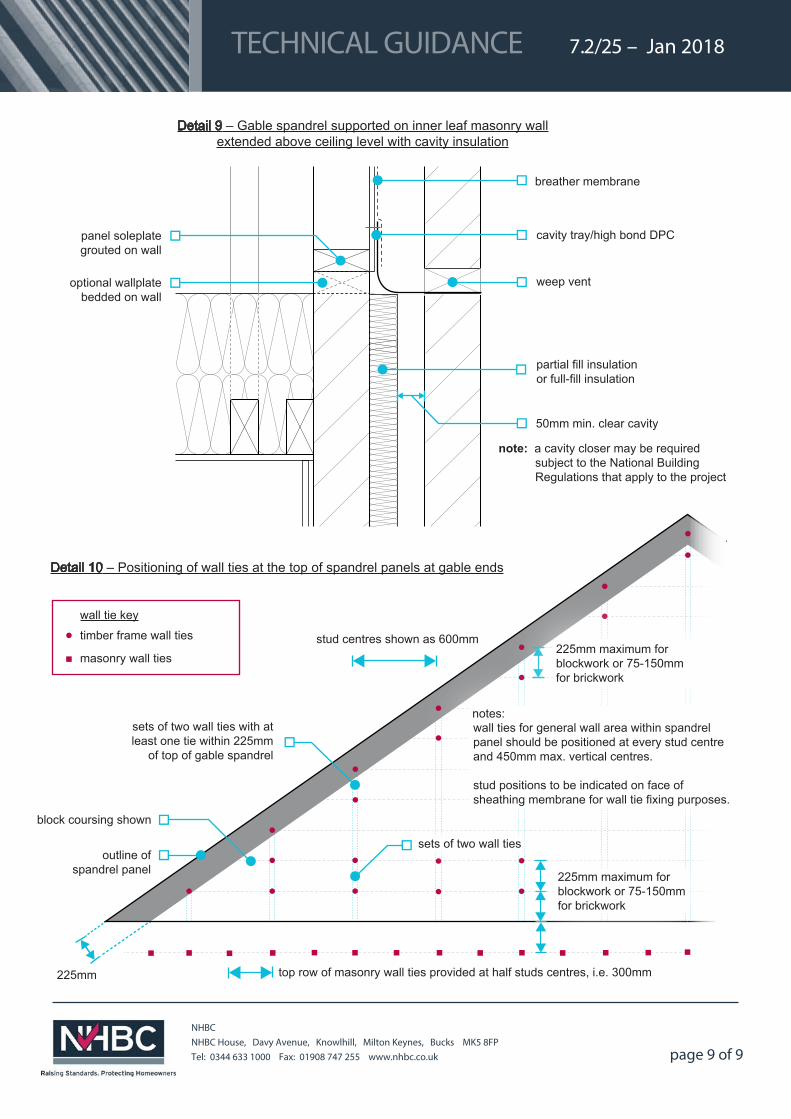
Detail 10 – Positioning of wall ties at the top of spandrel panels at gable ends
2 1
Option 1
6.1/25 – 2015 – 20147.2/25 – Jan 2018TECHNICAL GUIDANCE
page 9 of 9
NHBC NHBC House, Davy Avenue, Knowlhill, Milton Keynes, Bucks MK5 8FPTel: 0344 633 1000 Fax: 01908 747 255 www.nhbc.co.uk
note: a cavity closer may be required subject to the National Building Regulations that apply to the project
breather membrane
cavity tray/high bond DPC
weep vent
partial fill insulation or full-fill insulation
optional wallplate bedded on wall
panel soleplate grouted on wall
50mm min. clear cavity
Detail 9 – Gable spandrel supported on inner leaf masonry wall extended above ceiling level with cavity insulation
225mm
stud centres shown as 600mm
sets of two wall ties with at least one tie within 225mm
of top of gable spandrel
wall tie key
timber frame wall ties
masonry wall ties
notes:wall ties for general wall area within spandrel panel should be positioned at every stud centre and 450mm max. vertical centres.
stud positions to be indicated on face of sheathing membrane for wall tie fixing purposes.
block coursing shown
Detail 10 – Positioning of wall ties at the top of spandrel panels at gable ends
top row of masonry wall ties provided at half studs centres, i.e. 300mm
225mm maximum for blockwork or 75-150mm for brickwork
225mm maximum for blockwork or 75-150mm for brickwork
sets of two wall ties outline of
spandrel panel
Related Documents