A Summary of Discussions During the Seminar on Renewable Energy Systems GIOVANNI SPAGNUOLO, GIOVANNI PETRONE, SAMUEL VASCONCELOS ARAU ´ JO, CARLO CECATI, ERIK FRIIS-MADSEN, EUGENIO GUBI ´ A, DANIEL HISSEL, MAREK JASINSKI, WILFRIED KNAPP, MARCO LISERRE, PEDRO RODRIGUEZ, REMUS TEODORESCU, and PETER ZACHARIAS H ighly reliable and efficient power pro- cessing systems allow exploitation of the enormous potential of the re- newable sources by transforming the maximum available power into an electrical one, fed into the grid or converted into a high- density energy vector for being stored and used in another place or at another time, when the primary source is not available. Such topics were discussed at the Seminar on Renewable Energy system (SERENE) held 12–13 June 2009 in Salerno, Italy. The seminar was spon- sored by the University of Salerno and the IEEE Industrial Electronics Society (IES) through the Technical Committee on Renewable Energy Sys- tems and Educational Committee. This article is an attempt at sum- marizing the most important contri- butions of SERENE. It is organized as follows: first, the most promising future source of energy, i.e., photovol- taics (PVs), is treated with respect to the maximization of energy extrac- tion, the maximization of efficiency, and reliability with silicon carbide (SiC) devices and power converter structures; then, one of the most chal- lenging energy sources, wave energy, is discussed with reference to the results of the Wave Dragon European project; finally, integration of these sources into the power grid through smart-grid technologies based on the Digital Object Identifier 10.1109/MIE.2010.935863 © STOCKBYTE, DIGITAL VISION & PHOTODISC 38 IEEE INDUSTRIAL ELECTRONICS MAGAZINE n MARCH 2010 1932-4529/10/$26.00&2010IEEE

Welcome message from author
This document is posted to help you gain knowledge. Please leave a comment to let me know what you think about it! Share it to your friends and learn new things together.
Transcript
A Summary
of Discussions
During the
Seminar on
Renewable
Energy Systems
GIOVANNI SPAGNUOLO,GIOVANNI PETRONE,SAMUEL VASCONCELOSARAUJO, CARLO CECATI,ERIK FRIIS-MADSEN,EUGENIO GUBIA,DANIEL HISSEL,MAREK JASINSKI,WILFRIED KNAPP,MARCO LISERRE,PEDRO RODRIGUEZ,REMUS TEODORESCU,and PETER ZACHARIAS
Highly reliable and
efficient power pro-
cessing systems
allow exploitation
of the enormous
potential of the re-
newable sources by
transforming the maximum available
power into an electrical one, fed into
the grid or converted into a high-
density energy vector for being
stored and used in another place or
at another time, when the primary
source is not available.
Such topics were discussed at the
Seminar on Renewable Energy system
(SERENE) held 12–13 June 2009 in
Salerno, Italy. The seminar was spon-
sored by the University of Salerno
and the IEEE Industrial Electronics
Society (IES) through the Technical
Committee on Renewable Energy Sys-
tems and Educational Committee.
This article is an attempt at sum-
marizing the most important contri-
butions of SERENE. It is organized as
follows: first, the most promising
future source of energy, i.e., photovol-
taics (PVs), is treated with respect to
the maximization of energy extrac-
tion, the maximization of efficiency,
and reliability with silicon carbide
(SiC) devices and power converter
structures; then, one of the most chal-
lenging energy sources, wave energy,
is discussed with reference to the
results of the Wave Dragon European
project; finally, integration of these
sources into the power grid through
smart-grid technologies based on theDigital Object Identifier 10.1109/MIE.2010.935863
© STOCKBYTE, DIGITAL VISION & PHOTODISC
38 IEEE INDUSTRIAL ELECTRONICS MAGAZINE n MARCH 2010 1932-4529/10/$26.00&2010IEEE
grid converter and the use of hydrogen
as the main energy vector for station-
ary power plants are illustrated.
PV SystemsThe use of energy coming from the
Sun and hitting Earth has been dra-
matically increasing in the last few
years. Apart from the solar thermal
plants, the spreading of PV systems is
being encouraged by the feed-in tariffs
and by the drop in crystalline cells’
prices. The latter factor in 2009 has
boosted the sales of large PV power
plants as well as domestic installa-
tions, with a growing trend in 2010,
because the pay-back plan benefits of
tariffs for the produced energy still
remains high with respect to the fore-
cast for future years.
In this scenario, the market has
increased the need for power process-
ing systems characterized by high
efficiency and low cost, both for low-
power (e.g., few kilowatts) and high-
power applications. The former figure
can be improved by working on con-
version efficiency and maximum pow-
er point tracking (MPPT) efficiency,
whose product results in the total effi-
ciency of the power processing sys-
tem: SiC devices give a significant
contribution in maximizing the elec-
trical conversion efficiency, and an
in-depth analysis of the disturbances
appearing in grid-connected systems
helps in improving the MPPT effi-
ciency. The goal of exploiting several
distributed power sources with low-
voltage levels or to process high power
with lower current can be achieved
with multilevel architectures.
As for the cost aspect, current
literature indicates that the future of
PV-dedicated conversion systems is
in the adoption of transformerless
topologies, with additional benefits
in terms of conversion efficiency.
Such aspects have been detailed in
the sections that follow.
MPPT Issues
The MPPT is one of the key functions
in any PV system, because it ensures
that the maximum available electrical
power is produced by the PV array at
any irradiance and temperature val-
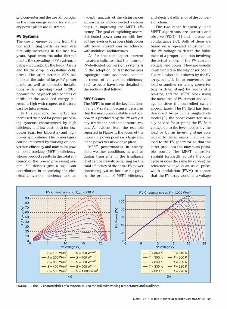
ues. As evident from the example
reported in Figure 1, the locus of the
maximum power points is a large area
in the power versus voltage plane.
MPPT performances in steady-
state weather conditions as well as
during transients in the irradiance
level can be heavily penalizing for the
total efficiency of the entire PV power
processing system, because it is given
by the product of MPPT efficiency
and electrical efficiency of the conver-
sion chain.
The two most frequently used
MPPT algorithms are perturb and
observe (P&O) [1] and incremental
conductance (IC). Both of them are
based on a repeated adjustment of
the PV voltage to detect the fulfill-
ment of a proper condition involving
the actual values of the PV current,
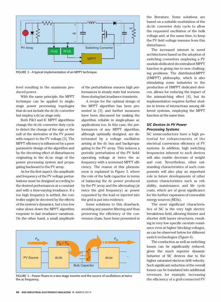
voltage, and power. They are usually
implemented in the way described in
Figure 2, where it is shown by the PV
array, a dc/dc boost converter, the
load or another switching converter
(e.g., a dc/ac stage) by means of a
resistor, and the MPPT block using
the measures of PV current and volt-
age to drive the controlled switch
appropriately. The PV field has been
described by using its single-diode
model [2], the boost converter, usu-
ally needed for stepping the PV field
voltage up to the level needed by the
load or by an inverting stage con-
nected to the ac mains, matches the
load to the PV generator so that the
latter produces the maximum possi-
ble power. The MPPT controller
straight forwardly adjusts the duty
cycle or does the same by varying the
reference voltage in an usual pulse-
width modulation (PWM) to ensure
that the PV array works at a voltage
0 5 10 15 200
10
20
30
40
50
60
70
80
90
PV Voltage (V)
(a)
PV
Pow
er (
W)
PV Characteristic at Tamb = 298 K
0 5 10 15 20 250
20
40
60
80
100
PV Voltage (V)
(b)
PV
Pow
er (
W)
PV Characteristic at S = 1,000 W/m2
T = 360 KT = 350 KT = 340 KT = 330 KT = 320 K
T = 310 KT = 300 KT = 290 KT = 280 KT = 270 K
S = 100 W/m2
S = 200 W/m2
S = 300 W/m2
S = 400 W/m2
S = 500 W/m2
S = 600 W/m2
S = 700 W/m2
S = 800 W/m2
S = 900 W/m2
S = 1,000 W/m2
FIGURE 1 – The PV characteristics of a Kyocera KC120 module with varying temperature and irradiance.
MARCH 2010 n IEEE INDUSTRIAL ELECTRONICS MAGAZINE 39
level resulting in the maximum pro-
duced power.
With the same principle, the MPPT
technique can be applied to single-
stage power processing topologies
that do not include the dc/dc converter
but employ a dc/ac stage only.
Both P&O and IC MPPT algorithms
change the dc/dc converter duty cycle
to detect the change of the sign or the
null of the derivative of the PV power
with respect to the PV voltage [3]. The
MPPT efficiency is influenced by a poor
parametric design of the algorithm and
by the deceiving effect of disturbances
originating in the dc/ac stage of the
power processing system and propa-
gating backward to the PV array.
As for the first aspect, the amplitude
and frequency of the PV voltage pertur-
bations must be designed according to
the desired performances at a constant
and with a time-varying irradiance. If a
too high frequency is settled, the con-
troller might be deceived by the effects
of the system’s dynamics, but a too low
value slows down the MPPT algorithm
response to fast irradiance variations.
On the other hand, a small amplitude
of the perturbations ensures high per-
formances in steady state but worsens
them during fast irradiance transients.
A recipe for the optimal design of
the MPPT algorithm has been pre-
sented in [3], and further measures
have been discussed for making the
algorithm reliable in single-phase ac
applications too. In this case, the per-
formances of any MPPT algorithm,
although optimally designed, are de-
teriorated by a voltage oscillation
arising at the dc bus and backpropa-
gating to the PV array. This induces a
periodic perturbation of the PV field-
operating voltage at twice the ac
frequency with a worsened MPPT effi-
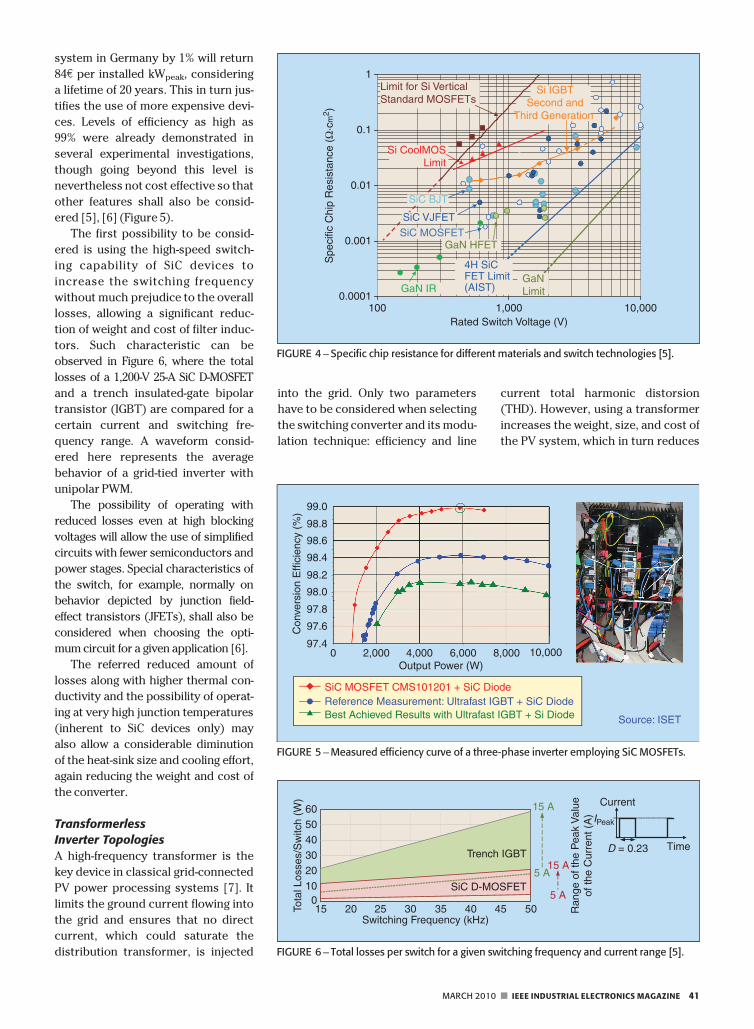
ciency. The reason of this phenom-
enon is explained in Figure 3, where
the role of the bulk capacitor in terms
of balancing the dc power produced
by the PV array and the alternating (at
twice the grid frequency) ac power
requested by the load or injected into
the grid is put into evidence.
Some solutions to this drawback,
avoiding any passive filtering and thus
preserving the efficiency of the con-
version chain, have been presented in
the literature. Some solutions are
based on a suitable modulation of the
dc/dc converter duty cycle to allow
the requested oscillation of the bulk
voltage and, at the same time, to keep
the PV field voltage immune from this
disturbance.
The increased interest in novel
architectures based on the adoption of
switching converters employing a PV
module-dedicated decentralized MPPT
function is giving rise to new challeng-
ing problems. The distributed-MPPT
(DMPPT) philosophy, which is also
stimulating some industries to the
production of DMPPT dedicated devi-
ces, allows for reducing the impact of
the mismatching effect [4], but its
implementation requires further stud-
ies in terms of interactions among dif-
ferent systems, employing the MPPT
function at the same time.
SiC Devices in PV Power
Processing Systems
SiC semiconductors have a high po-
tential for enhancements of the
electrical conversion efficiency of PV
systems. In addition, high switching
frequencies inherent to such devices
will also enable decrease of weight
and cost. Nevertheless, other out-
standing characteristics of such com-
ponents will also play an important
role in future developments of other
system characteristics such as reli-
ability, maintenance, and life cycle
costs, which are of great significance
for the further expansion of renewable
energy sources (RESs).
The most significant characteris-
tics of SiC is the very high electric
breakdown field, allowing thinner and
shorter drift layers structures, result-
ing in very low specific on-state resist-
ance even at higher blocking voltages,
as can be observed below for different
switch technologies (Figure 4).
The conduction as well as switching
losses can be significantly reduced,
given the much superior dynamic
behavior of SiC devices due to the
higher saturated electron drift velocity.
Such significant reduction of the overall
losses can be translated into additional
revenues; for example, increasing
the efficiency of a grid-connected PV
vp
vo+
−
PV Array Switching ConverterH (s) Hi (s)
MPPT
FIGURE 2 –A typical implementation of an MPPT technique.
PV Source dc/dc dc/ac ∼
Bulk Capacitor
Pdc Pac
Pac
> P
dc
Pdc > Pac
FIGURE 3 –Power fluxes in a two-stage inverter and the source of oscillations at twicethe ac frequency.
40 IEEE INDUSTRIAL ELECTRONICS MAGAZINE n MARCH 2010
system in Germany by 1% will return
84e per installed kWpeak, considering
a lifetime of 20 years. This in turn jus-
tifies the use of more expensive devi-
ces. Levels of efficiency as high as
99% were already demonstrated in
several experimental investigations,
though going beyond this level is
nevertheless not cost effective so that
other features shall also be consid-
ered [5], [6] (Figure 5).
The first possibility to be consid-
ered is using the high-speed switch-
ing capability of SiC devices to
increase the switching frequency
without much prejudice to the overall
losses, allowing a significant reduc-
tion of weight and cost of filter induc-
tors. Such characteristic can be
observed in Figure 6, where the total
losses of a 1,200-V 25-A SiC D-MOSFET
and a trench insulated-gate bipolar
transistor (IGBT) are compared for a
certain current and switching fre-
quency range. A waveform consid-
ered here represents the average
behavior of a grid-tied inverter with
unipolar PWM.
The possibility of operating with
reduced losses even at high blocking
voltages will allow the use of simplified
circuits with fewer semiconductors and
power stages. Special characteristics of
the switch, for example, normally on
behavior depicted by junction field-
effect transistors (JFETs), shall also be
considered when choosing the opti-
mum circuit for a given application [6].
The referred reduced amount of
losses along with higher thermal con-
ductivity and the possibility of operat-
ing at very high junction temperatures
(inherent to SiC devices only) may
also allow a considerable diminution
of the heat-sink size and cooling effort,
again reducing the weight and cost of
the converter.
Transformerless
Inverter Topologies
A high-frequency transformer is the
key device in classical grid-connected
PV power processing systems [7]. It
limits the ground current flowing into
the grid and ensures that no direct
current, which could saturate the
distribution transformer, is injected
into the grid. Only two parameters
have to be considered when selecting
the switching converter and its modu-
lation technique: efficiency and line
current total harmonic distorsion
(THD). However, using a transformer
increases the weight, size, and cost of
the PV system, which in turn reduces
0.001
0.01
0.1
1
10,0001,000100Rated Switch Voltage (V)
Spe
cific
Chi
p R
esis
tanc
e (Ω
·cm
2 )
SiC VJFET
SiC MOSFET
Si CoolMOSLimit
Limit for Si VerticalStandard MOSFETs
SiC BJT
0.0001
4H SiCFET Limit(AIST)
GaNLimitGaN IR
GaN HFET
Si IGBTSecond and
Third Generation
FIGURE 4 – Specific chip resistance for different materials and switch technologies [5].
99.0
98.8
98.6
98.4
98.2
98.0
97.8
97.6
97.40 2,000 4,000 6,000
Output Power (W)
Con
vers
ion
Effi
cien
cy (
%)
8,000 10,000
Source: ISET
SiC MOSFET CMS101201 + SiC DiodeReference Measurement: Ultrafast IGBT + SiC DiodeBest Achieved Results with Ultrafast IGBT + Si Diode
FIGURE 5 –Measured efficiency curve of a three-phase inverter employing SiC MOSFETs.
Switching Frequency (kHz)15 20 25 30 35 40 45 50
Trench IGBT
SiC D-MOSFET0
10
2030
4050
60
Tota
l Los
ses/
Sw
itch
(W)
15 A
5 A
15 A
5 A
Time
Current
IPeak
D = 0.23
Ran
ge o
f the
Pea
k V
alue
of th
e C
urre
nt (
A)
FIGURE 6 – Total losses per switch for a given switching frequency and current range [5].
MARCH 2010 n IEEE INDUSTRIAL ELECTRONICS MAGAZINE 41
its efficiency. These draw-
backs have motivated research-
ers to work on transformerless
solutions.
When the transformer is
removed from the system, the
common-mode behavior has to
be carefully considered. The cur-
rent injected into the ground is
only limited by the converter
common-mode impedances
[mainly due to the electromagnetic
compatibility (EMC) filter] and the
stray capacitance between the PV
generator and ground. This capaci-
tance is high enough to generate
strong leakage currents if the inverter
impresses a varying voltage across the
PV stray capacitance [8]. As a conse-
quence, in PV transformerless sys-
tems, the switching converter has to
be designed not only for high efficiency
and low THD but also to guarantee low
ground current injection [9]. Several
topologies, apparently based on very
different approaches, have been pro-
posed for single-phase transformerless
topologies [10]–[12]. Taking into ac-
count the general common mode
model derived in [8], all the topologies
can be systematically analyzed. As a
consequence, it is possible to obtain a
comprehensive picture of all the differ-
ent concepts used in those topologies.
Additionally, the analysis procedure
proposed becomes an useful tool to
analyze or derive other solutions.
As a preliminary step, the most
significant quality parameters to be
evaluated have been described. From
the energy generation point of view,
the main concern is about efficiency.
The main sources of power losses are
the converter switching and conduc-
tion losses and the energy losses in
the output filter. As the operation
point of a PV system changes contin-
uously, the efficiency should be ob-
tained considering several operation
points. In Europe, the Euro-efficiency
coefficient is commonly used for this
purpose. From the utility point of
view, the main concern is about the
line current harmonics, including the
dc component, and the current injec-
tion into the ground. The line current
THD is a function of the inverter out-
put voltage THD. The dc current
injection into the grid can be either
topologically avoided or controlled
by means of a current control loop.
Finally, the common-mode current
flowing through the ground is a func-
tion of the voltage impressed across
the stray capacitance of the PV gener-
ator to ground. To easily calculate
this voltage from any converter
topology is very useful to develop a
general model of a single-phase PV
system for the common mode. This
model can be derived considering
the switching converter as a two-
phase voltage source, with reference
to the negative rail of the dc
bus, and including the PV to
ground (CPVg) and the switches
to ground capacitances. The
model also has to include the
phase and neutral inductors, L1
and L2, and the common-mode
filter impedances LcmCcm. The
output voltage sources can be
expressed in terms of the usual
common-mode and differential-
mode components. From that model,
and after several considerations con-
cerning the frequency range of inter-
est and the relative value of the stray
capacitances, the simplified model
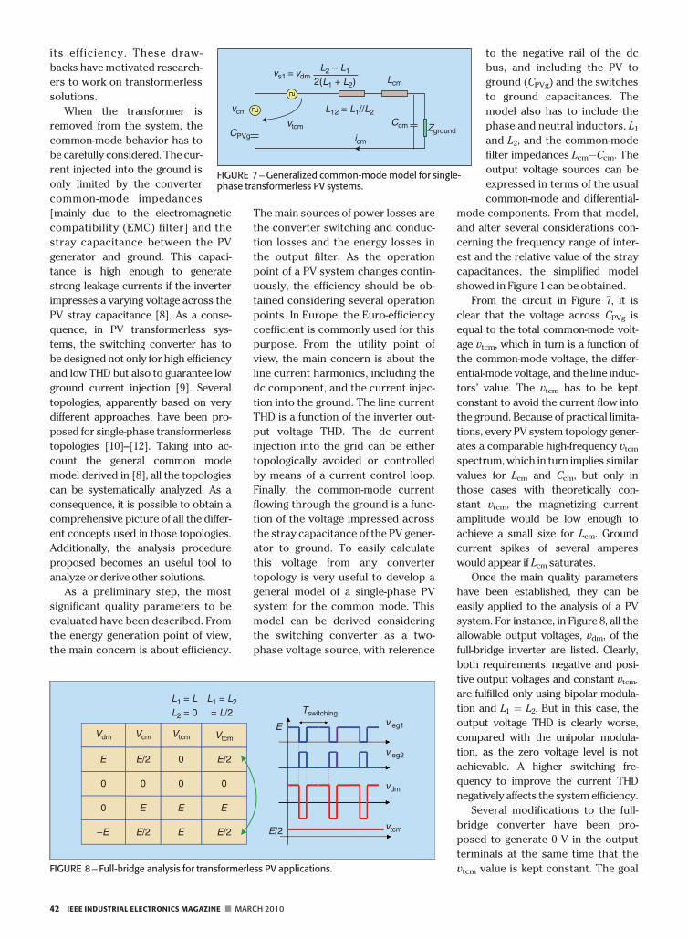
showed in Figure 1 can be obtained.
From the circuit in Figure 7, it is
clear that the voltage across CPVg is
equal to the total common-mode volt-
age vtcm, which in turn is a function of
the common-mode voltage, the differ-
ential-mode voltage, and the line induc-
tors’ value. The vtcm has to be kept
constant to avoid the current flow into
the ground. Because of practical limita-
tions, every PV system topology gener-
ates a comparable high-frequency vtcm
spectrum, which in turn implies similar
values for Lcm and Ccm, but only in
those cases with theoretically con-
stant vtcm, the magnetizing current
amplitude would be low enough to
achieve a small size for Lcm. Ground
current spikes of several amperes
would appear if Lcm saturates.
Once the main quality parameters
have been established, they can be
easily applied to the analysis of a PV
system. For instance, in Figure 8, all the
allowable output voltages, vdm, of the
full-bridge inverter are listed. Clearly,
both requirements, negative and posi-
tive output voltages and constant vtcm,
are fulfilled only using bipolar modula-
tion and L1 ¼ L2. But in this case, the
output voltage THD is clearly worse,
compared with the unipolar modula-
tion, as the zero voltage level is not
achievable. A higher switching fre-
quency to improve the current THD
negatively affects the system efficiency.
Several modifications to the full-
bridge converter have been pro-
posed to generate 0 V in the output
terminals at the same time that the
vtcm value is kept constant. The goal
vs1 = vdmL2 – L1
L12 = L1//L2
2(L1 + L2) Lcm
Ccm
vcm
CPVg icm
vtcm Zground
FIGURE 7 –Generalized common-mode model for single-phase transformerless PV systems.
Vdm Vcm Vtcm Vtcm
E E/2 0 E/2
0 E E E
–E E/2 E E/2
0 0 0 0
L1 = L
L2 = 0
L1 = L2
= L/2 Tswitching
E
E/2
vleg1
vleg2
vdm
vtcm
FIGURE 8 – Full-bridge analysis for transformerless PV applications.
42 IEEE INDUSTRIAL ELECTRONICS MAGAZINE n MARCH 2010
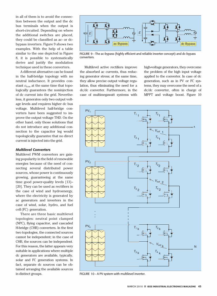
in all of them is to avoid the connec-
tion between the output and the dc
bus terminals when the output is
short-circuited. Depending on where
the additional switches are placed,
they could be classified as ac- or dc-
bypass inverters. Figure 9 shows two
examples. With the help of a table
similar to the one depicted in Figure
8, it is possible to systematically
derive and justify the modulation
technique used in these converters.
A different alternative can be found
in the half-bridge topology with no
neutral inductance. It provides con-
stant vtcm at the same time that topo-
logically guarantees the noninjection
of dc current into the grid. Neverthe-
less, it generates only two output volt-
age levels and requires higher dc bus
voltage. Multilevel half-bridge con-
verters have been suggested to im-
prove the output voltage THD. On the
other hand, only those solutions that
do not introduce any additional con-
nection to the capacitor leg would
topologically guarantee that no direct
current is injected into the grid.
Multilevel Converters
Multilevel PWM converters are gain-
ing popularity in the field of renewable
energies because of the need of con-
necting several distributed power
sources, whose power is continuously
growing, guaranteeing at the same
time good power-quality levels [13]–
[20]. They can be used as rectifiers in
the case of wind and hydroenergy,
where the electricity is generated by
ac generators and inverters in the
case of wind, solar, hydro, and fuel
cell (FC) generation.
There are three basic multilevel
topologies: neutral point clamped
(NPC), flying capacitor, and cascaded
H-bridge (CHB) converters. In the first
two topologies, the connected sources
cannot be independent; in the case of
CHB, the sources can be independent.
For this reason, the latter appears very
suitable in applications where multiple
dc generators are available, typically,
solar and FC generation systems. In
fact, separate dc sources can be ob-
tained arranging the available sources
in distinct groups.
Multilevel active rectifiers improve
the absorbed ac currents, thus reduc-
ing generator stress; at the same time,
they allow precise output voltage regu-
lation, thus eliminating the need for a
dc/dc converter. Furthermore, in the
case of multimegawatt systems with
high-voltage generators, they overcome
the problem of the high input voltage
applied to the converter. In case of dc
generation, such as in PV or FC sys-
tems, they may overcome the need of a
dc/dc converter, often in charge of
MPPT and voltage boost. Figure 10
ac Bypass dc Bypass
E E
FIGURE 9 – The ac-bypass (highly efficient and reliable inverter concept) and dc-bypassconverters.
T1 T2
T4
T2
T2
T4
T4
T3
T1
T1
T3
T3
1 1
1
2
1 1
Vout
Vout
Vout
2 2
22
k k
N
PVk
PV2
PV1
k
kk
A
FIGURE 10 –A PV system with multilevel inverter.
MARCH 2010 n IEEE INDUSTRIAL ELECTRONICS MAGAZINE 43
shows a schematic diagram of an
n-level inverter for solar systems.
The main drawbacks of multilevel
converters are the higher number of
power devices introducing potential
power losses problems and the com-
plexity of the pulse generation that
requires the design of ad hoc pattern
generators. Current electronic technol-
ogy overcomes both of them: in fact,
power devices (MOSFETs and IGBTs)
operating at low-voltage levels have bet-
ter characteristics than those operating
at low voltage, thus reducing or elimi-
nating this gap; moreover, the availabil-
ity of field-programmable gate arrays
(FPGAs) solves the second problem,
allowing the implementation on a single
chip of both control and modulation
algorithm at moderate cost.
Wave Dragon MW OffshoreWave Energy ConverterOceans cover approximately 75% of
our planet’s surface, and renewable
energy comes from the planet in dif-
ferent forms: waves, currents, thermal
gradients, salinity gradients, and tides
[21]. Until now, more than 1,000 pat-
ents have been dedicated to wave
energy converters aimed at exploiting
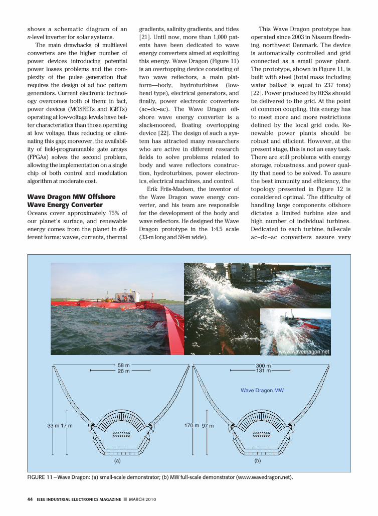
this energy. Wave Dragon (Figure 11)
is an overtopping device consisting of
two wave reflectors, a main plat-
form—body, hydroturbines (low-
head type), electrical generators, and
finally, power electronic converters
(ac–dc–ac). The Wave Dragon off-
shore wave energy converter is a
slack-moored, floating overtopping
device [22]. The design of such a sys-
tem has attracted many researchers
who are active in different research
fields to solve problems related to
body and wave reflectors construc-
tion, hydroturbines, power electron-
ics, electrical machines, and control.
Erik Friis-Madsen, the inventor of
the Wave Dragon wave energy con-
verter, and his team are responsible
for the development of the body and
wave reflectors. He designed the Wave
Dragon prototype in the 1:4.5 scale
(33-m long and 58-m wide).
This Wave Dragon prototype has
operated since 2003 in Nissum Bredn-
ing, northwest Denmark. The device
is automatically controlled and grid
connected as a small power plant.
The prototype, shown in Figure 11, is
built with steel (total mass including
water ballast is equal to 237 tons)
[22]. Power produced by RESs should
be delivered to the grid. At the point
of common coupling, this energy has
to meet more and more restrictions
defined by the local grid code. Re-
newable power plants should be
robust and efficient. However, at the
present stage, this is not an easy task.
There are still problems with energy
storage, robustness, and power qual-
ity that need to be solved. To assure
the best immunity and efficiency, the
topology presented in Figure 12 is
considered optimal. The difficulty of
handling large components offshore
dictates a limited turbine size and
high number of individual turbines.
Dedicated to each turbine, full-scale
ac–dc–ac converters assure very
58 m26 m
300 m131 m
Wave Dragon MW
170 m 97 m33 m 17 m
www.wavedragon.net
(a) (b)
FIGURE 11 –Wave Dragon: (a) small-scale demonstrator; (b) MW full-scale demonstrator (www.wavedragon.net).
44 IEEE INDUSTRIAL ELECTRONICS MAGAZINE n MARCH 2010
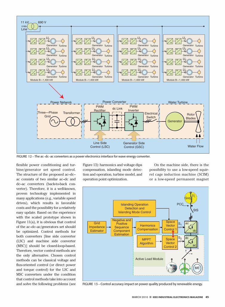
flexible power conditioning and tur-
bine/generator set speed control.
The structure of the proposed ac–dc–
ac consists of two similar ac–dc and
dc–ac converters (back-to-back con-
verter). Therefore, it is a well-known,
proven technology implemented in
many applications (e.g., variable speed
drives), which results in favorable
costs and the possibility for a relatively
easy update. Based on the experience
with the scaled prototype shown in
Figure 11(a), it is obvious that control
of the ac–dc–ac/generators set should
be optimized. Control methods for
both converters [line side converter
(LSC) and machine side converter
(MSC)] should be closed-loop-based.
Therefore, vector control methods are
the only alternative. Chosen control
methods can be classical voltage and
flux-oriented control (or direct power
and torque control) for the LSC and
MSC converters under the condition
that control methods take into account
and solve the following problems (see
Figure 13): harmonics and voltage dips
compensation, islanding mode detec-
tion and operation, turbine model, and
operation point optimization.
On the machine side, there is the
possibility to use a low-speed squir-
rel cage induction machine (SCIM)
or a low-speed permanent magnet
Islanding OperationDetection and
Islanding Mode Control
GridImpedanceEstimator
Negative andPositive
SequenceComponentEstimation
HarmonicsCompensation
MPPTAlgorithm
SpaceVector
Control 1
SpaceVector
Control 2
Active Load Module
ME
PCC
Grid
StS
ac
dc
dc
ac
S2
S1
UL
FIGURE 13 –Control accuracy impact on power quality produced by renewable energy.
~
~
~
~~
~
~
~==
==
==
==
U2
U2
U2
U2
Turbine
Turbine
Turbine
Turbine
Generator
Generator
Generator
GeneratorModule B—1,400 kW
~
~
~
~~
~
~
~==
==
==
==
U2
U2
U2
U2
Turbine
Turbine
Turbine
Turbine
Generator
Generator
Generator
GeneratorModule B—1,400 kW
~
~
~
~~
~
~
~==
==
==
==
U2
U2
U2
U2
Turbine
Turbine
Turbine
Turbine
Generator
Generator
Generator
GeneratorModule B—1,400 kW
~
~
~
~~
~
~
~==
==
==
==
U2
U2
U2
U2
Turbine
Turbine
Turbine
Turbine
Generator
Generator
Generator
GeneratorModule B—1,400 kW
Power Network
Three—PhaseGrid
Transformer
PWMRectifier
PWMInverter
ElectricalSwitch
Generator
RotorBlades
Line SideControl (LSC)
Generator SideControl (GSC) Water Flow
dc Link
Power Converter Water Turbine
11 kV 690 V
Line
FIGURE 12 – The ac–dc–ac converters as a power electronics interface for wave energy converter.
MARCH 2010 n IEEE INDUSTRIAL ELECTRONICS MAGAZINE 45
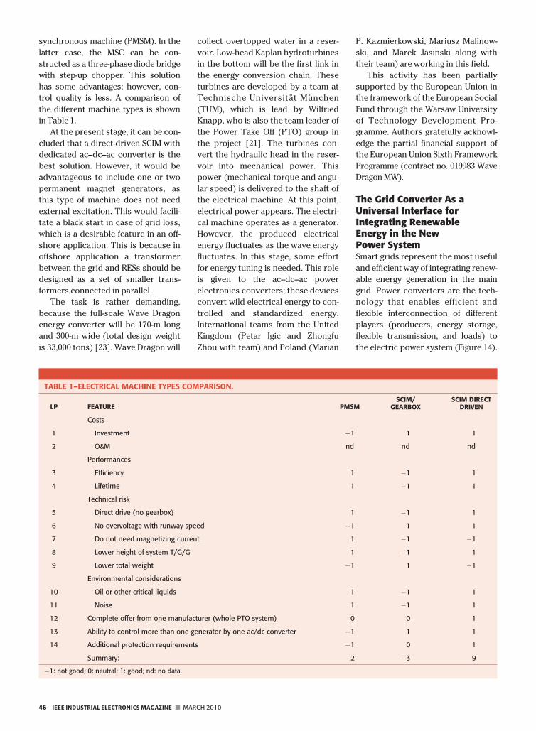
synchronous machine (PMSM). In the
latter case, the MSC can be con-
structed as a three-phase diode bridge
with step-up chopper. This solution
has some advantages; however, con-
trol quality is less. A comparison of
the different machine types is shown
in Table 1.
At the present stage, it can be con-
cluded that a direct-driven SCIM with
dedicated ac–dc–ac converter is the
best solution. However, it would be
advantageous to include one or two
permanent magnet generators, as
this type of machine does not need
external excitation. This would facili-
tate a black start in case of grid loss,
which is a desirable feature in an off-
shore application. This is because in
offshore application a transformer
between the grid and RESs should be
designed as a set of smaller trans-
formers connected in parallel.
The task is rather demanding,
because the full-scale Wave Dragon
energy converter will be 170-m long
and 300-m wide (total design weight
is 33,000 tons) [23]. Wave Dragon will
collect overtopped water in a reser-
voir. Low-head Kaplan hydroturbines
in the bottom will be the first link in
the energy conversion chain. These
turbines are developed by a team at
Technische Universitat Munchen
(TUM), which is lead by Wilfried
Knapp, who is also the team leader of
the Power Take Off (PTO) group in
the project [21]. The turbines con-
vert the hydraulic head in the reser-
voir into mechanical power. This
power (mechanical torque and angu-
lar speed) is delivered to the shaft of
the electrical machine. At this point,
electrical power appears. The electri-
cal machine operates as a generator.
However, the produced electrical
energy fluctuates as the wave energy
fluctuates. In this stage, some effort
for energy tuning is needed. This role
is given to the ac–dc–ac power
electronics converters; these devices
convert wild electrical energy to con-
trolled and standardized energy.
International teams from the United
Kingdom (Petar Igic and Zhongfu
Zhou with team) and Poland (Marian
P. Kazmierkowski, Mariusz Malinow-
ski, and Marek Jasinski along with
their team) are working in this field.
This activity has been partially
supported by the European Union in
the framework of the European Social
Fund through the Warsaw University
of Technology Development Pro-
gramme. Authors gratefully acknowl-
edge the partial financial support of
the European Union Sixth Framework
Programme (contract no. 019983 Wave
Dragon MW).
The Grid Converter As aUniversal Interface forIntegrating RenewableEnergy in the NewPower SystemSmart grids represent the most useful
and efficient way of integrating renew-
able energy generation in the main
grid. Power converters are the tech-
nology that enables efficient and
flexible interconnection of different
players (producers, energy storage,
flexible transmission, and loads) to
the electric power system (Figure 14).
TABLE 1–ELECTRICAL MACHINE TYPES COMPARISON.
LP FEATURE PMSMSCIM/
GEARBOXSCIM DIRECT
DRIVEN
Costs
1 Investment 1 1 1
2 O&M nd nd nd
Performances
3 Efficiency 1 1 1
4 Lifetime 1 1 1
Technical risk
5 Direct drive (no gearbox) 1 1 1
6 No overvoltage with runway speed 1 1 1
7 Do not need magnetizing current 1 1 1
8 Lower height of system T/G/G 1 1 1
9 Lower total weight 1 1 1
Environmental considerations
10 Oil or other critical liquids 1 1 1
11 Noise 1 1 1
12 Complete offer from one manufacturer (whole PTO system) 0 0 1
13 Ability to control more than one generator by one ac/dc converter 1 1 1
14 Additional protection requirements 1 0 1
Summary: 2 3 9
1: not good; 0: neutral; 1: good; nd: no data.
46 IEEE INDUSTRIAL ELECTRONICS MAGAZINE n MARCH 2010
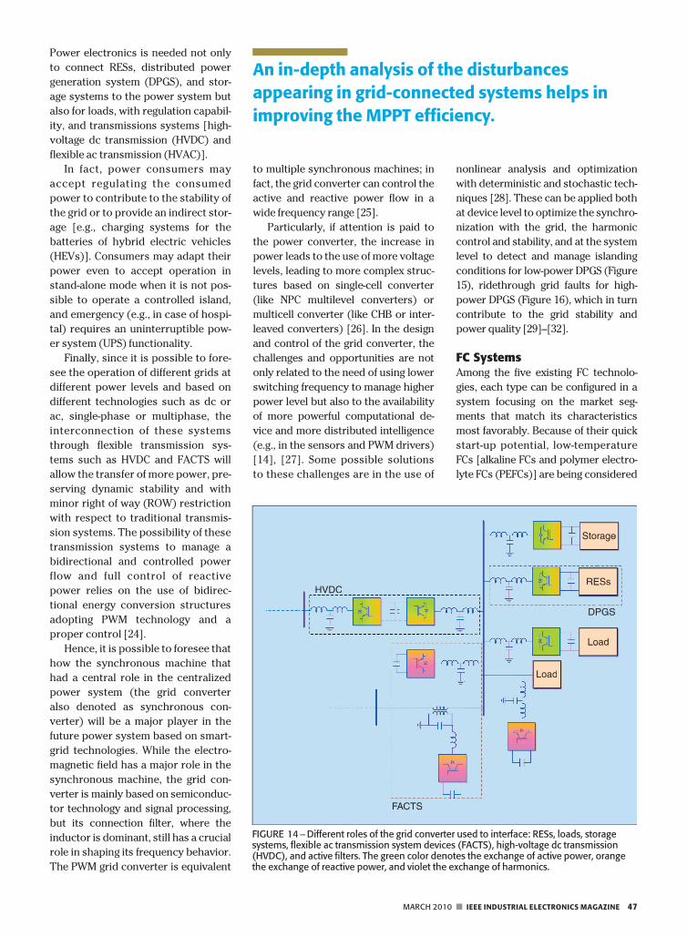
Power electronics is needed not only
to connect RESs, distributed power
generation system (DPGS), and stor-
age systems to the power system but
also for loads, with regulation capabil-
ity, and transmissions systems [high-
voltage dc transmission (HVDC) and
flexible ac transmission (HVAC)].
In fact, power consumers may
accept regulating the consumed
power to contribute to the stability of
the grid or to provide an indirect stor-
age [e.g., charging systems for the
batteries of hybrid electric vehicles
(HEVs)]. Consumers may adapt their
power even to accept operation in
stand-alone mode when it is not pos-
sible to operate a controlled island,
and emergency (e.g., in case of hospi-
tal) requires an uninterruptible pow-
er system (UPS) functionality.
Finally, since it is possible to fore-
see the operation of different grids at
different power levels and based on
different technologies such as dc or
ac, single-phase or multiphase, the
interconnection of these systems
through flexible transmission sys-
tems such as HVDC and FACTS will
allow the transfer of more power, pre-
serving dynamic stability and with
minor right of way (ROW) restriction
with respect to traditional transmis-
sion systems. The possibility of these
transmission systems to manage a
bidirectional and controlled power
flow and full control of reactive
power relies on the use of bidirec-
tional energy conversion structures
adopting PWM technology and a
proper control [24].
Hence, it is possible to foresee that
how the synchronous machine that
had a central role in the centralized
power system (the grid converter
also denoted as synchronous con-
verter) will be a major player in the
future power system based on smart-
grid technologies. While the electro-
magnetic field has a major role in the
synchronous machine, the grid con-
verter is mainly based on semiconduc-
tor technology and signal processing,
but its connection filter, where the
inductor is dominant, still has a crucial
role in shaping its frequency behavior.
The PWM grid converter is equivalent
to multiple synchronous machines; in
fact, the grid converter can control the
active and reactive power flow in a
wide frequency range [25].
Particularly, if attention is paid to
the power converter, the increase in
power leads to the use of more voltage
levels, leading to more complex struc-
tures based on single-cell converter
(like NPC multilevel converters) or
multicell converter (like CHB or inter-
leaved converters) [26]. In the design
and control of the grid converter, the
challenges and opportunities are not
only related to the need of using lower
switching frequency to manage higher
power level but also to the availability
of more powerful computational de-
vice and more distributed intelligence
(e.g., in the sensors and PWM drivers)
[14], [27]. Some possible solutions
to these challenges are in the use of
nonlinear analysis and optimization
with deterministic and stochastic tech-
niques [28]. These can be applied both
at device level to optimize the synchro-
nization with the grid, the harmonic
control and stability, and at the system
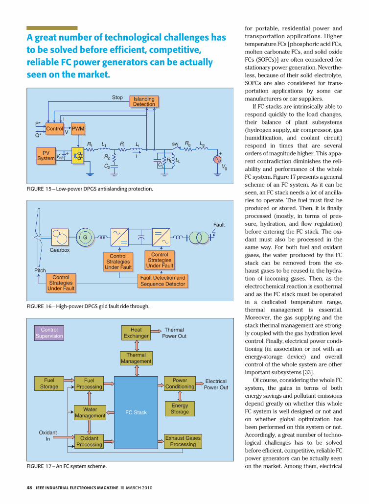
level to detect and manage islanding
conditions for low-power DPGS (Figure
15), ridethrough grid faults for high-
power DPGS (Figure 16), which in turn
contribute to the grid stability and
power quality [29]–[32].
FC SystemsAmong the five existing FC technolo-
gies, each type can be configured in a
system focusing on the market seg-
ments that match its characteristics
most favorably. Because of their quick
start-up potential, low-temperature
FCs [alkaline FCs and polymer electro-
lyte FCs (PEFCs)] are being considered
HVDC
FACTS
Storage
DPGS
RESs
Load
Load
HVDC
Storage
DPGS
RESs
Load
Load
FIGURE 14 –Different roles of the grid converter used to interface: RESs, loads, storagesystems, flexible ac transmission system devices (FACTS), high-voltage dc transmission(HVDC), and active filters. The green color denotes the exchange of active power, orangethe exchange of reactive power, and violet the exchange of harmonics.
An in-depth analysis of the disturbances
appearing in grid-connected systems helps in
improving the MPPT efficiency.
MARCH 2010 n IEEE INDUSTRIAL ELECTRONICS MAGAZINE 47
for portable, residential power and
transportation applications. Higher
temperature FCs [phosphoric acid FCs,
molten carbonate FCs, and solid oxide
FCs (SOFCs)] are often considered for
stationary power generation. Neverthe-
less, because of their solid electrolyte,
SOFCs are also considered for trans-
portation applications by some car
manufacturers or car suppliers.
If FC stacks are intrinsically able to
respond quickly to the load changes,
their balance of plant subsystems
(hydrogen supply, air compressor, gas
humidification, and coolant circuit)
respond in times that are several
orders of magnitude higher. This appa-
rent contradiction diminishes the reli-
ability and performance of the whole
FC system. Figure 17 presents a general
scheme of an FC system. As it can be
seen, an FC stack needs a lot of ancilla-
ries to operate. The fuel must first be
produced or stored. Then, it is finally
processed (mostly, in terms of pres-
sure, hydration, and flow regulation)
before entering the FC stack. The oxi-
dant must also be processed in the
same way. For both fuel and oxidant
gases, the water produced by the FC
stack can be removed from the ex-
haust gases to be reused in the hydra-
tion of incoming gases. Then, as the
electrochemical reaction is exothermal
and as the FC stack must be operated
in a dedicated temperature range,
thermal management is essential.
Moreover, the gas supplying and the
stack thermal management are strong-
ly coupled with the gas hydration level
control. Finally, electrical power condi-
tioning (in association or not with an
energy-storage device) and overall
control of the whole system are other
important subsystems [33].
Of course, considering the whole FC
system, the gains in terms of both
energy savings and pollutant emissions
depend greatly on whether this whole
FC system is well designed or not and
on whether global optimization has
been performed on this system or not.
Accordingly, a great number of techno-
logical challenges has to be solved
before efficient, competitive, reliable FC
power generators can be actually seen
on the market. Among them, electrical
ControlSupervision
HeatExchanger
ThermalPower Out
ElectricalPower Out
FuelStorage
FuelProcessing
ThermalManagement
PowerConditioning
EnergyStorage
Exhaust GasesProcessing
OxidantProcessing
WaterManagement
OxidantIn
FC Stack
FIGURE 17 –An FC system scheme.
Pitch
Gearbox
G
Fault
ControlStrategies
Under Fault
ControlStrategies
Under Fault
ControlStrategies
Under Fault
Fault Detection andSequence Detector
FIGURE 16 –High-power DPGS grid fault ride through.
Control
IslandingDetection
Stop
PWM
i
V
P*
Q*
PVSystem Vdc
R1
R2
C2CL
Rg
Vg
Lgsw
RL LL
L1 LiRi
i+ +
FIGURE 15 – Low-power DPGS antiislanding protection.
A great number of technological challenges has
to be solved before efficient, competitive,
reliable FC power generators can be actually
seen on the market.
48 IEEE INDUSTRIAL ELECTRONICS MAGAZINE n MARCH 2010
engineering relating technological chal-
lenges are of greatest importance.
n Modeling challenges have to be
overcome. The difficulty is here to
propose an efficient, easy-to-tune,
real-time suitable model of the
whole FC system. Many solutions
have already been proposed: ana-
lytical models, gray and black-box
models [34].
n New power conversion solutions
have to be proposed for those
high-current, low-voltage power
devices. The coupling (and the
relating optimization) of the FC
stack with electrical energy-stor-
age devices (e.g., supercapaci-
tors and batteries of flywheels)
has to be investigated to propose
new high-efficient hybridized pow-
er architectures.
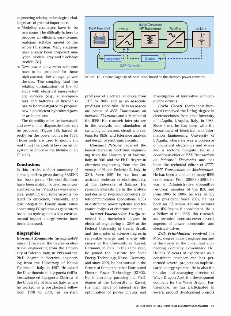
The durability must be increased,
and new online diagnostic tools can
be proposed (Figure 18), based di-
rectly on the power converter [35].
Those tools are used to modify (in
real time) the control laws on an FC
system to improve the lifetime of an
FC stack.
ConclusionsIn this article, a short summary of
some speeches given during SERENE
has been given. The contributions
have been mainly focused on power
electronics for PV and sea wave ener-
gies, pointing out some aspects re-
lated to efficiency, reliability, and
grid integration. Finally, main issues
concerning FC systems as generators
based on hydrogen as a low environ-
mental impact energy vector have
been discussed.
BiographiesGiovanni Spagnuolo (gspagnuolo@
unisa.it) received the degree in elec-
tronic engineering from the Univer-
sity of Salerno, Italy, in 1993 and the
Ph.D. degree in electrical engineer-
ing from the University of Napoli
Federico II, Italy, in 1997. He joined
the Dipartimento di Ingegneria dell’In-
formazione ed Ingegneria Elettrica of
the University of Salerno, Italy, where
he worked as a postdoctoral fellow
from 1998 to 1999, an assistant
professor of electrical sciences from
1999 to 2003, and as an associate
professor since 2004. He is an associ-
ate editor of IEEE Transactions on
Industrial Electronics and a Member of
the IEEE. His research interests are
in the analysis and simulation of
switching converters, circuit and sys-
tems for RESs, and tolerance analysis
and design of electronic circuits.
Giovanni Petrone received the
laurea degree in electronic engineer-
ing from the University of Salerno,
Italy, in 2001 and the Ph.D. degree in
electrical engineering from the Uni-
versity of Napoli Federico II, Italy, in
2004. Since 2005, he has been an
assistant professor of electrotechnics
at the University of Salerno. His
research interests are in the analysis
and design of switching converters for
telecommunication applications, RESs
in distributed power systems, and tol-
erance analysis of electronic circuits.
Samuel Vasconcelos Araujo re-
ceived the bachelor’s degree in
electrical engineering in 2006 at the
Federal University of Ceara, Brazil,
and the master of science degree in
renewable energy and energy effi-
ciency at the University of Kassel,
Germany, in 2007. In the same year,
he joined the Institute for Solar
Energy Technology, Kassel, Germany,
and since 2009, he has worked in the
Center of Competence for Distributed
Electric Power Technology (KDEE).
He is currently pursuing his Ph.D.
degree at the University of Kassel.
His main fields of interest are the
optimization of power circuits and
investigation of innovative semicon-
ductor devices.
Carlo Cecati (carlo.cecati@uni-
vaq.it) received the Dr.Ing. degree in
electrotechnics from the University
of L’Aquila, L’Aquila, Italy, in 1983.
Since then, he has been with the
Department of Electrical and Infor-
mation Engineering, University of
L’Aquila, where he was a professor
of industrial electronics and drives
and a rector’s delegate. He is a
coeditor-in-chief of IEEE Transactions
on Industrial Electronics and has
been the technical editor of IEEE/
ASME Transactions on Mechatronics.
He has been a cochair of many IEEE
conferences. From 2000 to 2004, he
was an Administrative Committee
(AdCom) member of the IES, and
from 2005 to 2006, he was an IES
vice president. Since 2007, he has
been an IES senior AdCom member
and IES Region 8 coordinator. He is
a Fellow of the IEEE. His research
and technical interests cover several
aspects of power electronics and
electrical drives.
Erik Friis-Madsen received his
M.Sc. degree in civil engineering and
is the owner of the consultant engi-
neering company Lowenmark FRI.
He has 35 years of experience as a
consultant engineer and has per-
formed several projects on sophisti-
cated energy systems. He is also the
founder and managing director of
Wave Dragon ApS, the development
company for the Wave Dragon. Fur-
thermore, he has participated in
several product development projects
PEM Fuel Cell dc-Link
+
−
Inverter HF Transformer Rectifierdc/dc Converter
Diagnosis Control
DSP Controller
FIGURE 18 –Online diagnosis of the FC stack based on the electrical power converter.
MARCH 2010 n IEEE INDUSTRIAL ELECTRONICS MAGAZINE 49
within the construction industry. He
is a council member of the Danish
Association of Engineers and a mem-
ber of the board of the Danish Soci-
ety of Wave Energy.
Eugenio Gubıa received the
M.Sc. and Ph.D. degrees in industrial
engineering from the Public Univer-
sity of Navarre, Spain, in 1995 and
2003, respectively. He joined the
Electrical and Electronic Depart-
ment of the Public University of Nav-
arre in 1996, where he is currently an
associate professor. In 2002, he
joined the Electrical Engineering,
Power Electronics, and Renewable
Energy Research Group. From June
to December 2005, he worked as a
guest researcher at the Center for
Power Electronics Systems (CPES) in
the field of electromagnetic compati-
bility. His research interests are in
the field of power electronics, renew-
able energy systems, onboard sys-
tems, high-frequency phenomena in
electrical machines, and electromag-
netic compatibility.
Daniel Hissel obtained an electri-
cal engineering degree from the Ecole
Nationale Superieure d’Ingenieurs
Electriciens de Grenoble in 1994. He
received a Ph.D. degree from the
Institut National Polytechnique de
Toulouse in 1998. From 1999 to 2000,
he worked for ALSTOM Transport in
Tarbes, France, where he was a sys-
tem engineer on electrical and FC
bus projects. From 2000 to 2006, he
was an associate professor at the
University of Technology Belfort. From
2006 to 2008, he was a full professor
at the University of Franche-Comte
and the head of the Fuel Cell Systems
Research Team of the Laboratory of
Electrical Engineering and Systems.
Since 2008, he has been a full profes-
sor at the University of Franche-Comte
and head of the energy systems mod-
eling research team at the Franche-
Comte Electronic, Mechanical, Thermal,
Optical-Sciences and Technology
(French National Centre for Scien-
tific Research) Institute. He is an asso-
ciate editor of IEEE Transactions on
Industrial Electronics and an associate
editor of ASME Fuel Cell Science and
Technology. He is also the president
of the IEEE Vehicular Technology
Society French Chapter and a mem-
ber of the advisory board of the
French National Network on Electric
Vehicles and HEV. He is a member of
the Fuel Cell Laboratory Institute
(dedicated to FC research) and has
published more than 150 scientific
papers in peer-reviewed international
journals and international conferen-
ces. He is a Senior Member of the
IEEE. His research activities are
concerning FC systems dedicated to
automotive and stationary applica-
tions, modeling, nonlinear control, and
energy optimization of these systems
and FC system diagnosis.
Marek Jasinski received the
M.Sc.E.E. degree with distinction in
electrical engineering from the In-
stitute of Control and Industrial
Electronics, Warsaw University of
Technology (WUT), Poland, in 2000.
He is currently with the Institute of
Control and Industrial Electronics,
WUT. Since 2006, he has worked on
the Wave Dragon project in the PTO
group (power electronics energy con-
version and generator control). In
2009, he worked as a guest re-
searcher of the Vestas Power Pro-
gram. He is a Member of the IEEE.
His research activity deals with the
control of ac–dc–ac converters.
Wilfried Knapp graduated with
a diploma in mechanical engineering
from TUM in 1984. Since 1984, he
has worked as a research assistant
with the Institute for Hydraulic Ma-
chinery and Plants, TUM. He re-
ceived a Ph.D. degree in 1990 on
investigations of performance curve
instabilities in centrifugal pumps. He
is the head of the laboratory at
Lehrstuhl fur Fluidmechanik, TUM.
Marco Liserre ([email protected])
received the M.Sc. and Ph.D. de-
grees in electrical engineering from
the Polytechnic of Bari, Italy, in 1998
and 2002, respectively. Since Janu-
ary 2004, he has been an assistant
professor with the Polytechnic of
Bari, where he is engaged in teach-
ing courses of power electronics,
industrial electronics, and EMs. He
has authored or coauthored more
than 127 technical papers and has
authored three book chapters. He
was a visiting professor at Aalborg
University, Denmark, Alcala de Henares,
Spain, and at Christian-Albrechts Uni-
versity of Kiel, Germany. He has given
lectures at different universities and
tutorials for the following conferences:
IEEE Energy Conversion Congress and
Exposition 2009, IEEE Power Electron-
ics Specialists Conference 2008, ISIE
2008, European Conference on Power
Electronics and Applications (EPE)
2007, Annual Conference of the IECON
2006, ISIE 2006, and IECON 2005. He
was a reviewer for international con-
ferences and journals. Within the IES,
he has been responsible for student
activities, an AdCom member, an edi-
tor of the newsletter, and responsible
for Region 8 membership activities.
He is an associate editor of IEEE
Transactions on Industrial Electronics.
He is the founder of IEEE Industrial
Electronics Magazine, and he was also
editor-in-chief from 2007 to 2009. He
received the IES 2009 Early Career
Award. Currently, he is the IEEE-IES
vice president for publications. His
research interests include industrial
electronics applications to DPGSs
based on renewable energies. He is a
senior member of the IES, the Power
Electronics Society, and the Industry
Applications Society.
Pedro Rodriguez received the
B.S. degree from the University of
Granada, Spain, in 1989, and the
M.S. and Ph.D. degrees from the
Technical University of Catalonia
(UPC), Barcelona, Spain, in 1994 and
2004, respectively, all in electrical
engineering. In 1990, he was an
assistant professor at UPC, where
he became an associate professor in
1993. In 2005, he was a researcher at
the CPES, Virginia Polytechnic Insti-
tute and State University, Blacks-
burg. In 2006, he was a researcher
in the Institute of Energy Technol-
ogy, Aalborg University, Denmark.
He is currently the head of the Re-
search Group on Renewable Electri-
cal Energy Systems, Department of
Electrical Engineering. He has auth-
ored or coauthored more than 100
papers in technical journals and con-
ferences and holds two patents. He
50 IEEE INDUSTRIAL ELECTRONICS MAGAZINE n MARCH 2010
is a member of PELS, IES, and IAS.
He is also a Member of the IEEE.
His research interests include power
conditioning, integration of distrib-
uted energy systems, and control of
power converters.
Remus Teodorescu received
the Dipl.Ing. degree in electrical engi-
neering from Polytechnical University
of Bucharest, Romania, in 1989 and
the Ph.D. degree in power electronics
from the University of Galati, Romania,
in 1994. In 1998, he joined Aalborg
University, where he currently works
as a full professor. He published
more than 120 papers, one book, and
has three patents pending. He was a
corecipient of the Technical Commit-
tee Prize Paper Award at the 1998
IEEE IAS Annual Meeting and the
Third ABB Prize Paper Award at the
2002 IEEE Optim. He is a Senior Mem-
ber of the IEEE, associate editor for
IEEE Power Electronics Letters, and
chair of the IEEE Danish joint IES/
PELS/IAS Chapter. He is the founder
and coordinator of the Green Power
Laboratory at Aalborg. His research
interests include design and control
of power converters used in renew-
able energy systems, distributed gen-
eration, mainly wind power and PVs,
computer simulations, and digital con-
trol implementation.
Peter Zacharias received the
Dipl.-Ing. and Dr.-Ing. degrees in elec-
trical engineering from Otto-von-Gue-
ricke University Magdeburg, Germany,
in 1979 and 1981, respectively. He
worked at the University of Magde-
burg until 1990 as an associate pro-
fessor for power electronics. From
1990 to 1995, he worked at Lambda
Physik GmbH Goettingen and later
joined ISET Kassel, Germany. He then
joined Eupec GmbH in Warstein, Ger-
many. In 2005, he joined the Univer-
sity of Kassel as a professor for
electric power supply systems. He
founded the KDEE in 2009.
References[1] N. Femia, G. Petrone, G. Spagnuolo, and
M. Vitelli, ‘‘A technique for improvingP&O MPPT performances of double-stagegrid-connected photovoltaic systems,’’IEEE Trans. Ind. Electron., vol. 56, no. 11,pp. 4473–4482, Nov. 2009.
[2] G. Petrone, G. Spagnuolo, and M. Vitelli,
‘‘Analytical model of mismatched
photovoltaic fields by means of LambertW-function,’’ Sol. Energy. Mater. Sol. Cells,vol. 91, no. 18, pp. 1652–1657, Nov. 2007.
[3] N. Femia, G. Petrone, G. Spagnuolo, and
M. Vitelli, ‘‘Optimization of perturb andobserve maximum power point trackingmethod,’’ IEEE Trans. Power. Electron.,vol. 20, no. 4, pp. 963–973, July 2005.
[4] N. Femia, G. Lisi, G. Petrone, G. Spagnuolo,and M. Vitelli, ‘‘Distributed maximum powerpoint tracking of photovoltaic arrays: Novelapproach and system analysis,’’ IEEE Trans.Ind. Electron., vol. 55, no. 7, pp. 2610–2621,
July 2008.
[5] B. Sahan, S. V. Araujo, T. Kirstein, L.Menezes, and P. Zacharias, ‘‘Photovoltaicconverter topologies suitable for SiC-JFETs,’’in Proc. European Conf. Power Conversionand Intelligent Motion (PCIM), May 2009.
[6] S. V. Araujo and P. Zacharias, ‘‘Analysis onthe potential of silicon carbide MOSFETsand other innovative semiconductor tech-nologies in the photovoltaic branch,’’ inProc. 13th European Conf. Power Electronicsand Applications (EPE), Sept. 2009.
[7] M. Cacciato, A. Consoli, R. Attanasio, andF. Gennaro, ‘‘Soft-switching converter withHF transformer for grid-connected photo-voltaic systems,’’ IEEE Trans. Ind. Electron.,to be published.
[8] E. Gubia, P. Sanchis, A. Ursua, J. Lopez,and L. Marroyo, ‘‘Ground currents in sin-gle-phase transformerless photovoltaicsystems,’’ Prog. Photovoltaics: Res. Appl.,vol. 15, no. 7, pp. 629–650, Nov. 2007.
[9] C. Cavalcanti, C. Oliveira, M. Farias, A. S.Neves, M. S. Azevedo, and C. Camboim,‘‘Modulation techniques to eliminate leak-age currents in transformerless three-
phase photovoltaic systems,’’ IEEE Trans.Ind. Electron., to be published.
[10] S. B. Kjaer, J. K. Pedersen, and F. Blaabjerg,‘‘A review of single-phase grid-connectedinverters in photovoltaic modules,’’ IEEETrans. Ind. Applicat., vol. 41, no. 5, pp. 1292–1306, 2005.
[11] R. Gonzalez, E. Gubıa, J. Lopez, and L. Mar-royo, ‘‘Transformerless single-phase multi-
level-based photovoltaic inverter,’’ IEEETrans. Ind. Electron., vol. 55, no. 7, pp. 2694–2702, July 2008.
[12] S. Araujo, P. Zacharias, and R. Mallwitz,‘‘Highly efficient single-phase transformer-less inverters for grid-connected photovol-taic systems,’’ IEEE Trans. Ind. Electron., tobe published.
[13] J. R. Rodriguez and J.-S. Peng, ‘‘Multilevel
inverters: A survey of topologies, control,and applications,’’ IEEE Trans. Ind. Elec-tron., vol. 49, no. 4, pp. 724–738, 2002.
[14] L. G. Franquelo, J. Rodriguez, J. I. Leon, S.Kouko, R. Portillo, and M. A. M. Prats, ‘‘Theage of multilevel converters arrives,’’ IEEEInd. Electron. Mag., vol. 2, no. 2, pp. 28–39,June 2008.
[15] H. Ertl, J. W. Kolar, and F. C. Zach, ‘‘A
novel multicell DC-AC converter for appli-cations in renewable energy systems,’’IEEE Trans. Ind. Electron., vol. 49, no. 5,pp. 1048–1057, 2002.
[16] S. Alepuz, S. Busquets-Monge, J. Bordonau,J. Gago, D. Gonzalez, and J. Balcells, ‘‘Inter-facing renewable energy sources to theutility grid using a three-level inverter,’’IEEE Trans. Ind. Electron., vol. 53, no. 5,
pp. 1504–1511, 2006.[17] E. Villanueva, P. Correa, J. Rodriguez, and M.
Pacas, ‘‘Control of a single-phase cascadedH-bridge multilevel inverter for grid-con-nected photovoltaic systems,’’ IEEE Trans.Ind. Electron., vol. 56, no. 11, pp. 4399–4406,2009.
[18] E. Ozdemir, S. Ozdemir, and L. M. Tolbert,‘‘Fundamental-frequency-modulated six-
level diode-clamped multilevel inverter for
three-phase stand-alone photovoltaic sys-tem,’’ IEEE Trans. Ind. Electron., vol. 56,no. 11, pp. 4407–4415, 2009.
[19] G. Grandi, C. Rossi, D. Ostojic, and D. Casa-dei, ‘‘A new multilevel conversion struc-ture for grid-connected PV applications,’’IEEE Trans. Ind. Electron., vol. 56, no. 11,pp. 4416–4424, 2009.
[20] C. Cecati, F. Ciancetta, and P. Siano, ‘‘A mul-tilevel inverter for photovoltaic systemswith fuzzy logic control,’’ IEEE Trans. Ind.Electron., vol. 57, 2010, submitted forpublication.
[21] Renewable Energy Technologies. Ocean
energy conversion in Europe. Published inthe framework of the Co-ordinated Actionon Ocean Energy. EU project under FP6Priority: 6.1.3.2.3 [Online]. Available: http://www.ca-oe.org
[22] Available: http://www.wavedragon.net/
[23] L. Christensen, E. Friis-Madsen, J. PeterKofoed, and J. Tedd, ‘‘Worlds largest waveenergy project 2007 in Wales,’’ in Proc.PoweGen 2006 Conf.
[24] S. Cole and R. Belmans, ‘‘High voltagedirect current: From large-scale powertransmission to flexible transmission sys-tems,’’ IEEE Ind. Electron. Mag., vol. 3, no. 4,pp. 19–24, Dec. 2009.
[25] F. Blaabjerg, R. Teodorescu, M. Liserre,and A. V. Timbus, ‘‘Overview of controland grid synchronization for distributedpower systems,’’ IEEE Trans Ind. Electron.,vol. 53, no. 5, pp. 1398–1409, Oct. 2006.
[26] J. M. Carrasco, L. G. Franquelo, J. T. Biala-siewicz, E. Galvan, R. C. P. Guisado, M. M.Prats, J. I. Leon, and N. Moreno-Alfonso,‘‘Power electronic systems for the gridintegration of renewable energy sources:
A survey,’’ IEEE Trans. Ind. Electron.,vol. 53, no. 4, pp. 1002–1016, Aug. 2006.
[27] J. Wang, A. Huang, W. Sung, Y. Liu, and B.J. Baliga, ‘‘Smart grid technologies,’’ IEEEInd. Electron. Mag., vol. 3, no. 2, pp. 16–23,June 2009.
[28] J.S. Lai, ‘‘Power conditioning circuit topol-ogies,’’ IEEE Ind. Electron. Mag., vol. 3,no. 2, pp. 24–34, June 2009.
[29] M. Liserre, A. Dell’aquila, and F. Blaabjerg,‘‘Genetic algorithm-based design of theactive damping for an LCL-filter three-phase active rectifier,’’ IEEE Trans. PowerElectron., vol. 19, no. 1, pp. 76–86, Jan.2004.
[30] P. Rodriguez, A. Timbus, R. Teodorescu,M. Liserre, and F. Blaabjerg, ‘‘Flexibleactive power control of distributed power
generation systems during grid faults,’’IEEE Trans. Ind. Electron., vol. 54, no. 5,pp. 2583–2592, Oct. 2007.
[31] P. Rodrıguez, A. Timbus, R. Teodorescu,M. Liserre, and F. Blaabjerg, ‘‘Reactivepower control for improving wind turbinesystems behaviour under grid faults,’’IEEE Trans. Power Electron., vol. 24, no. 7,pp. 1798–1801, July 2009.
[32] R. A. Mastromauro, M. Liserre, T. Kerekes,and A. Dell’aquila, ‘‘A single-phase voltagecontrolled grid connected photovoltaicsystem with power quality conditionerfunctionality,’’ IEEE Trans. Ind. Electron.,vol. 56, no. 11, pp. 4436–4444, Nov. 2009.
[33] M. C. Pera, D. Candusso, D. Hissel, and J.M. Kauffmann, ‘‘Power generation by fuelcells,’’ IEEE Ind. Electron. Mag., vol. 1,
no. 3, pp. 28–37, Fall 2007.[34] S. Jeme€ı, D. Hissel, M. C. Pera, and J. M.
Kauffmann, ‘‘A new modeling approach ofembedded fuel cell generators based onartificial neural network,’’ IEEE Trans. Ind.Electron., vol. 55, no. 1, pp. 437–447, 2008.
[35] A. Narjiss, D. Depernet, D. Candusso, F.Gustin, and D. Hissel, ‘‘Online diagnosis ofPEM fuel cells,’’ in Proc. EPE-PEMFC Conf.,Poznan, Poland, 2008, pp. 749–754.
MARCH 2010 n IEEE INDUSTRIAL ELECTRONICS MAGAZINE 51
Related Documents