Spaceborne Radar Monitoring of Forest Fires and Forest Cover Change A case study in Kalimantan Ruandha Agung Sugardiman

Welcome message from author
This document is posted to help you gain knowledge. Please leave a comment to let me know what you think about it! Share it to your friends and learn new things together.
Transcript

Spaceborne Radar Monitoring of Forest Fires and Forest Cover Change
A case study in Kalimantan
Ruandha Agung Sugardiman
Tropenbos‐Kalimantan Series The Tropenbos‐Kalimantan Series presents the results of studies and research activities related to sustainable use and conservation of forest resources in Indonesia. The multi‐disciplinary MOF‐Tropenbos Kalimantan programme operates within the framework of the international programme of Tropenbos International. Executing agency is the Forestry Research Institute, Samarinda, governed by the Forestry Research and Development Agency (FORDA) of the Ministry of Forestry.
Ministry of Forestry of
The Republic of Indonesia
The International MOF-Tropenbos
Kalimantan Programme
Wageningen University The Netherlands
NUFFIC, The Netherlands
The Gibbon Foundation
The Borneo Orangutan Survival Foundation (BOS)
Tropenbos International

Spaceborne Radar Monitoring of Forest Fires and Forest Cover Change
A case study in Kalimantan
Ruandha Agung Sugardiman
Proefschrift ter verkrijging van de graad van doctor
op gezag van de Rector Magnificus van Wageningen Universiteit
Prof.dr. M.J. Kropff in het openbaar te verdedigen op woensdag 25 april 2007
des namiddags te 13.30 uur in de Aula

Ruandha Agung Sugardiman E-Mail: [email protected] [email protected] Ruandha Agung Sugardiman, 2007 Spaceborne radar monitoring of forest fires and forest cover change. A case study in Kalimantan/ Sugardiman, R.A. PhD thesis Wageningen University, Wageningen, The Netherlands, with references and summaries in English and Dutch. ISSN: 1566-6522 ISBN-13: 978-90-5113-087-4 (Tropenbos version) ISBN: 90-8504-604-1 (Thesis version) © 2007 MOF – Tropenbos-Kalimantan Programme, R.A. Sugardiman The opinions expressed in this publication are those of the author and do not necessarily reflect the views of Tropenbos International. No part of this publication, apart from bibliographic data and brief quotations in critical reviews, may be reproduced, re-recorded or published in any form including print photocopy, microfilm, and electromagnetic record without the prior written permission. Cover: Satellites ERS, ENVISAT, SRTM and ALOS; Multi-temporal ERS-2 SAR
composite and 3D view. Courtesy to ESA, NASA and JAXA. Printed by Drukkerij Ponsen en Looijen BV., Wageningen, the Netherlands

…Éb> §‘ ’ ÎΤ÷Š Η $ Vϑù= Ïã ∩⊇⊇⊆∪
ʺ…O my Lord!, advance me in knowledge.ʺ (QS 20 Thaahaa: 114)
This book is dedicated to My late best friend, DR. Ir. H. Muljanto Nugroho, MF and to My special ladies in my life, R.S. Sumadijani, R. Maryani,
R. Primarista, R. Dwiannisa

Foreword “Seeing is believing” is the notion that drives my interests in conducting this study on monitoring changes in forest condition. Having being educated as a traditional forester in a country rich with forest resources, I believe the resource will face eternal demand. Tropical rainforest spreads from coastal to mountainous areas and stretches across thousands of islands of Indonesia, an observation made possible thanks to the advancement of technology needed to monitor and observe those resources. In my professional career, remote sensing, as a tool, enables me to witness rapid changes in the condition of forestry resources which are now disappearing faster than our eyes can blink. This drives me to not only keep an eye on these rapid changes but to keep up with changes of the tool itself. My first encounter with such changes started with the application of aerial photogrammetry; during that time it was considered the most reliable data source in forestry. Afterwards, it brought me further toward larger scales with the use of conventional optical satellite images that provide ‘an interesting performance’ with astonishing colour combination, but tends to overlook complete features. My interest in the changes of forestry resources which are persistently covered by clouds and/or smoke and have thus never been mapped brought me into the field of radar application. It has taught me that forest fires, flooding, and landslides are all dramatic events. Moreover, exploitation and illegal logging are accelerating at a rapid pace. Such events change the resource base very rapidly and it may constrain efforts and possibilities for conserving the resource. The trend, however, can be prevented as we begin to understand historical changes. So, in writing this dissertation, it is the very process of writing that gives my life a ‘certain historical meaning’. Those strengthen my belief for doing the right thing and do it right for preserving the resource without delay. Already 1400 years ago, this message was clearly conveyed: ‘Even when the End Of The Day arrives tomorrow, and in the hands of one of you there is a seedling which he can plant before he is overwhelmed by the Hour, then let him do so’ (Muhammad Rasulullah). This message gives me confidence that tropical rainforests will never vanish. It is expected that with those efforts and awareness, the results of this study will also be useful for monitoring forest regrowth. Therefore, I believe tropical rainforests “Tomorrow never dies”. (Muhammad PBUH, Hadith Ahmed, Al-Bukhari in al -Adabul Mufrad).
i

ii
iii
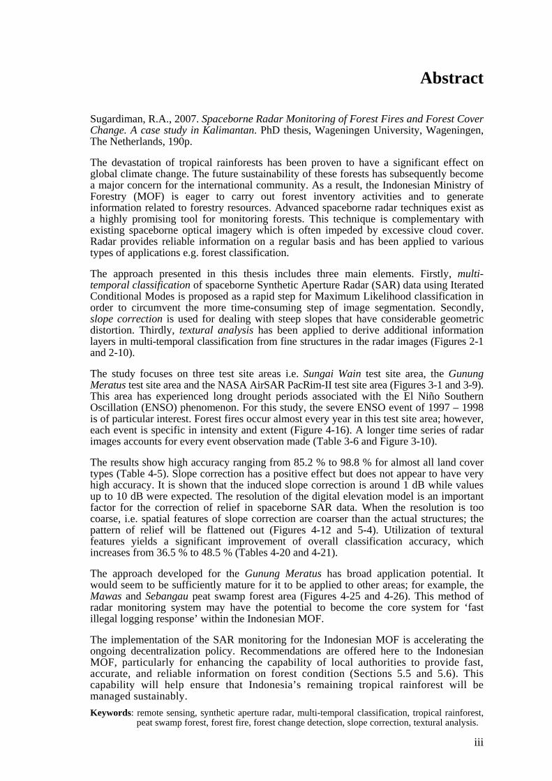
Abstract Sugardiman, R.A., 2007. Spaceborne Radar Monitoring of Forest Fires and Forest Cover Change. A case study in Kalimantan. PhD thesis, Wageningen University, Wageningen, The Netherlands, 190p. The devastation of tropical rainforests has been proven to have a significant effect on global climate change. The future sustainability of these forests has subsequently become a major concern for the international community. As a result, the Indonesian Ministry of Forestry (MOF) is eager to carry out forest inventory activities and to generate information related to forestry resources. Advanced spaceborne radar techniques exist as a highly promising tool for monitoring forests. This technique is complementary with existing spaceborne optical imagery which is often impeded by excessive cloud cover. Radar provides reliable information on a regular basis and has been applied to various types of applications e.g. forest classification. The approach presented in this thesis includes three main elements. Firstly, multi-temporal classification of spaceborne Synthetic Aperture Radar (SAR) data using Iterated Conditional Modes is proposed as a rapid step for Maximum Likelihood classification in order to circumvent the more time-consuming step of image segmentation. Secondly, slope correction is used for dealing with steep slopes that have considerable geometric distortion. Thirdly, textural analysis has been applied to derive additional information layers in multi-temporal classification from fine structures in the radar images (Figures 2-1 and 2-10). The study focuses on three test site areas i.e. Sungai Wain test site area, the Gunung Meratus test site area and the NASA AirSAR PacRim-II test site area (Figures 3-1 and 3-9). This area has experienced long drought periods associated with the El Niño Southern Oscillation (ENSO) phenomenon. For this study, the severe ENSO event of 1997 – 1998 is of particular interest. Forest fires occur almost every year in this test site area; however, each event is specific in intensity and extent (Figure 4-16). A longer time series of radar images accounts for every event observation made (Table 3-6 and Figure 3-10). The results show high accuracy ranging from 85.2 % to 98.8 % for almost all land cover types (Table 4-5). Slope correction has a positive effect but does not appear to have very high accuracy. It is shown that the induced slope correction is around 1 dB while values up to 10 dB were expected. The resolution of the digital elevation model is an important factor for the correction of relief in spaceborne SAR data. When the resolution is too coarse, i.e. spatial features of slope correction are coarser than the actual structures; the pattern of relief will be flattened out (Figures 4-12 and 5-4). Utilization of textural features yields a significant improvement of overall classification accuracy, which increases from 36.5 % to 48.5 % (Tables 4-20 and 4-21). The approach developed for the Gunung Meratus has broad application potential. It would seem to be sufficiently mature for it to be applied to other areas; for example, the Mawas and Sebangau peat swamp forest area (Figures 4-25 and 4-26). This method of radar monitoring system may have the potential to become the core system for ‘fast illegal logging response’ within the Indonesian MOF. The implementation of the SAR monitoring for the Indonesian MOF is accelerating the ongoing decentralization policy. Recommendations are offered here to the Indonesian MOF, particularly for enhancing the capability of local authorities to provide fast, accurate, and reliable information on forest condition (Sections 5.5 and 5.6). This capability will help ensure that Indonesia’s remaining tropical rainforest will be managed sustainably. Keywords: remote sensing, synthetic aperture radar, multi-temporal classification, tropical rainforest,
peat swamp forest, forest fire, forest change detection, slope correction, textural analysis.
iv
Content
Foreword .........................................................................................................................i
Abstract .........................................................................................................................iii
Content...........................................................................................................................iv
List of Abbreviations ....................................................................................................vi
List of Symbols...............................................................................................................x
1 INTRODUCTION....................................................................................................1
1.1 The decline of tropical rainforests ....................................................................1 1.2 Current operational constraints in Indonesia ....................................................3 1.3 The potential of radar monitoring.....................................................................4 1.4 Study approach .................................................................................................6 1.5 Study objectives................................................................................................8 1.6 Structure of the thesis .......................................................................................9
2 MULTI-TEMPORAL SAR CLASSIFICATION WITH SLOPE CORRECTION AND TEXTURAL ANALYSIS ................................................11
2.1 Multi-temporal Synthetic Aperture Radar images..........................................11 2.2 General methodological framework ...............................................................12 2.3 The imaging principle.....................................................................................15 2.4 Slopes, height and orthorectification ..............................................................16 2.5 Slope correction model ...................................................................................19 2.6 Interferometric and polarimetric radar ...........................................................22 2.7 Iterated Conditional Modes ............................................................................23 2.8 Textural analysis of radar images...................................................................25 2.9 Summary and conclusions ..............................................................................27
3 THE TROPICAL RAINFOREST: ITS DYNAMICS FROM SPACE AND TERRESTRIAL .....................................................................................................29
3.1 Introduction ....................................................................................................29 3.2 Climate............................................................................................................30 3.3 Geology and topography ................................................................................32 3.4 Soils ................................................................................................................32 3.5 Land systems ..................................................................................................33 3.6 Rivers..............................................................................................................35 3.7 Road network..................................................................................................36 3.8 Land cover and land use in the test site area ..................................................37 3.9 Forest fires – its behaviour and impact on the test site area ...........................40
3.9.1 Fire behaviour.........................................................................................40 3.9.2 Potential factors causing forest fire in Indonesia....................................43
3.10 ERS and ENVISAT SAR time series acquisition ..........................................44 3.11 NASA/JPL Airborne SAR data ......................................................................50 3.12 Shuttle radar topography mission data..............................................................52 3.13 In situ data collection......................................................................................54 3.14 Summary and conclusions ..............................................................................57

v
4 LAND COVER CLASSIFICATION, FOREST FIRE AND CHANGE DETECTION ......................................................................................................... 59
4.1 Introduction.................................................................................................... 59 4.2 An ERS-SAR multi-temporal image of the Sungai Wain area ...................... 60 4.3 Initial validation study at 20 km x 18 km Sungai Wain test site area ............ 61
4.3.1 Initial ERS-SAR data set ........................................................................61 4.3.2 Heuristic and hierarchical multi-temporal classification ........................64 4.3.3 Forest fire risk and forest damage evaluation.........................................68
4.4 Monitoring the 90 km x 70 km Gunung Meratus test site area ..................... 70 4.4.1 Additional ERS-SAR data sets ...............................................................70 4.4.2 A more generalised approach by introducing Iterated Conditional
Modes .....................................................................................................72 4.4.3 Forest cover change application .............................................................74
4.5 Slope correction to improve forest cover classification................................. 79 4.6 Textural analysis to enhance forest cover classification................................ 84 4.7 Coherence of repeat-pass interferometry to improve forest cover
classification: an introduction ........................................................................ 86 4.8 Discussion on NOAA-AVHRR hotspots observations.................................. 87 4.9 Peat swamp forest monitoring: operational implementation ......................... 90 4.10 Results of peat swamp forest monitoring....................................................... 94 4.11 Summary and conclusions ............................................................................. 99
5 IMPLEMENTATION OF SAR MONITORING FOR INDONESIAN FORESTRY: OUTLOOK TO THE FUTURE................................................. 105
5.1 Fire scar detection in airborne L- and P-band and the use of high-resolution DEM............................................................................................ 105
5.2 Limitations of short time series in spaceborne C-band for fire scar detection ....................................................................................................... 109
5.3 The advantages of a multi-sensor advanced radar remote sensing system .. 112 5.4 Future Spaceborne Synthetic Aperture Radar sensors ................................. 116 5.5 Implementation for Indonesian forestry....................................................... 118 5.6 Conclusions and recommendations.............................................................. 120
Summary and Conclusions....................................................................................... 123
Samenvatting en Conclusies ..................................................................................... 131
References .................................................................................................................. 141
Index ........................................................................................................................... 153
Appendices ................................................................................................................. 155 Appendix A : Tropical rainforest..................................................................... 156 Appendix B : Maximum Likelihood Classification ........................................ 158 Appendix C : The Error Matrix ....................................................................... 160 Appendix D : KAPPA Analysis....................................................................... 162 Appendix E : Textural analysis using Grey Level Co-Occurrence technique 164 Appendix F : Landsat data .............................................................................. 166 Appendix G : Field data................................................................................... 170 Appendix H : Future Synthetic Aperture Radar sensor ................................... 178
Acknowledgements.................................................................................................... 185
Curriculum Vitae ...................................................................................................... 187
List of Publications.................................................................................................... 189
vi
List of Abbreviations
Abbreviation Description
3D Three dimensional AirSAR Airborne Synthetic Aperture Radar ALOS Advanced Land Observing Satellite nicknamed “Daichi” AMI Active Microwave Instrument ARCBC ASEAN Regional Centre for Biodiversity Conservation ASAR Advanced Synthetic Aperture Radar ASL Above Sea Level ATI Along-Track Interferometry AVHRR Advanced Very High Resolution Radiometer BAKOSURTANAL ”Badan Koordinasi Survey dan Pemetaan Nasional” National Coordinating Agency for Surveys and Mapping BBC British Broadcasting Corporation BFI Balikpapan Forest Industries BOS Borneo Orang-utan Survival Foundation C-band Radar band; wavelength 7.5 – 3.75 cm, frequency 4 – 8 GHz CSIRO Commonwealth Scientific and Industrial Research Organization Australia's national science agency DEM Digital Elevation Model DLR “Deutschland für Luft- und Raumfahrt” German Aerospace Centre DoSAR Dornier Synthetic Aperture Radar EADS European Aeronautic Defence and Space E-SAR Experimental Synthetic Aperture Radar EGM Earth Gravitational Model ENSO El Niño Southern Oscillation ENVISAT ENVIronmental SATellite EORC Earth Observation Research Center EROS Earth Resources Observation & Science ERS European Remote Sensing Satellite ERS-1, ERS-2 European Remote Sensing Satellite – one, – two ERS-SAR European Remote Sensing Satellite – Synthetic Aperture RadarETFRN European Tropical Forest Research Network ESA European Space Agency ESRIN European Space Research Institute (ESA facility, Frascati, Italy)FAO Food and Agriculture Organization of the United Nations FAME Forest Assessment and Monitoring Environment

vii
FMIS Forest Management Information System FOMAS Forest Monitoring and Assessment System FWI Forest Watch Indonesia GF Gibbon Foundation GFW Global Forest Watch GIS Geographical Information System GLCF Global Land Cover Facility GLCO Grey Level Co-Occurrence GMAP Gamma Maximum A Posteriori GMES Global Monitoring for Environment and Security GMT Greenwich Mean Time GPS Global Positioning System GTZ "Deutsche Gesellschaft für Technische Zusammenarbeit" German Agency for Technical Cooperation ICM Iterated Conditional Modes IEEE Institute of Electrical and Electronics Engineers (U.S.) IFFM Integrated Forest Fire Management IFSAR InterFerometric Synthetic Aperture Radar INDREX INDonesian Radar EXperiment InSAR Interferometric Synthetic Aperture Radar IQL Interferometric Quick Look ISPRS International Society of Photogrammetry and Remote Sensing ITC International Institute for Aerospace Survey and Earth Sciences, currently International Institute for Geo-Information Science and Earth Observation ITCI International Timber Corporation Indonesia JAXA Japan Aerospace eXploration Agency JAROS Japan Resources Observation System Organization JD Julian Date JDN Julian Day Number JERS Japanese Earth Resources Satellite JERS-1 Japanese Earth Resources Satellite – one JPL Jet Propulsion Laboratory L-band Radar band; wavelength 30 – 15 cm, frequency 1 – 2 GHz Landsat ETM+ Landsat Enhanced Thematic Mapper Plus Landsat TM Landsat Thematic Mapper LAPAN “Lembaga Penerbangan dan Antariksa Nasional” Indonesian National Institute of Aeronautics and Space LOA Logged over area MASTER Modis/Aster Airborne Simulator MERIS Medium Resolution Imaging Spectrometer

viii
ML Maximum Likelihood MODIS Moderate Resolution Imaging Spectroradiometer MOF Ministry of Forestry MRF Markov Random Field MSL Mean Sea Level NASA National Aeronautics and Space Administration (U.S.) NDVI Normalized Difference Vegetative Index NFI National Forest Inventory NGA National Geospatial-Intelligence Agency (U.S.) NIVR The Netherlands Agency for Aerospace Programmes NOAA National Oceanic and Atmospheric Administration (U.S.) NUSP National Users Support Programme (The Netherlands) P-band Radar band; wavelength 136 – 77 cm, frequency 220 – 390 MHz PacRim-II Pacific Rim 2000 campaign PALSAR Phased Array type L-band Synthetic Aperture Radar PDOP Positional Dilution of Precision POLSAR Polarimetric Synthetic Aperture Radar PRI Precision Images RePPProT Regional Physical Planning Programme for Transmigration RGB Red-Green-Blue ROI Regions of Interest SAR Synthetic Aperture Radar SAREX South American Radar Experiment SPOT “Satellite Pour l'Observation de La Terre” Earth Observation SatelliteSRTM Shuttle Radar Topography Mission TOPSAR Topographic Synthetic Aperture Radar TRFRC Tropical Rain Forest Research Centre TT Terrestrial Time ULA Ultra Light Aircraft UN United Nations UNCED United Nations Conference on Environment and DevelopmentUSGS United States Geological Survey UT, UTC Universal Time, Universal Time Coordinated UTM Universal Transverse Mercator WGS World Geodetic System WPT Waypoint WRS Worldwide Reference System WRI World Resources Institute WWF World Wildlife Fund XTI Cross-Track Interferometry

x
List of Symbols
Symbol Description Unit
A Sub-satellite point (Nadir) - B Interferometric baseline m |Ci| Determinant of Ci - Ci Covariance matrix - C Centre of the Earth - CV Coefficient of Variation - D Standardized threshold distance - | d | Displacement length - H Height above the earth’s spherical surface (geoid) m h Height above ellipsoid m lhi,c Likelihood of a pixel i belonging to class c - Mi Mean value vector - mlhic ICM modified likelihood of a pixel i belonging to class c - mx, my Mean value of the row and column position - N Difference between ellipsoid and geoid m Ng Number of image grey levels - n Number of ICM-cycles - Pc Relative occurrence of class c - pc Chance agreement - po Actual agreement - p(i, j) Probability value of the GLCO matrix - R Radius of the Earth m Ri,c Relief factor for pixel i and class c - S Position of the satellite - sx, sy Standard deviation of the row and column position - t0 Transmitted pulse duration - ti Logarithmic version of the coefficient of variation - Ti Threshold value - Ti,c Texture factor for pixel i and class c - Tmc Mean of the textural coefficient of variation for class c - Tvc Variance of the textural coefficient of variation for class c - ui,c number of neighbouring pixels of pixel i having class c - X Observation vector -
xi
α Angle of slope o βi Factor defining the relative influence of prior information - βT Factor defining a threshold for the influence of texture information - γ Differential radar cross section per unit projected area m2 m-2
γf Differential radar cross section per unit slope area m2 m-2
γi Differential radar cross section per unit projected area for field i m2 m-2
∂ S Horizontal distance m ∂ Z Vertical distance (elevation) m Δt Time interval between transmission and reception of the pulse “ Θ Degree of slope o θgr Grazing angle o θ i Incidence angle o
Κ̂ Kappa statistic - σ Radar cross section dB σ
0 Differential radar cross section m2 m-2
φ Displacement direction -
Ψ Compass direction (azimuth) o
C h a p t e r
1 __________________
1 INTRODUCTION "Promote the development and wider use of earth observation technologies, including satellite remote sensing, global mapping and geographic information systems, to collect quality data on environmental impacts, land use and land-use changes,.." (Plan of Implementation of the World Summit on Sustainable Development, United Nation Publication, Johannesburg, South Africa, 26 August – 4 September 2002)
1.1 The decline of tropical rainforests Tropical rainforests cover large parts of the Earth's land surface. The significance of these forests, and the need for information, can be seen from several perspectives. They play an important role in global hydrological, biochemical and energy cycles and, thus, in the Earth's climate. They also are of large economic value as a major source of timber and other products, and as a source of land. Large areas are converted into forest plantations, arable land and pastures. Since these types of land use are often unsustainable, large areas of barren wastelands emerge (Smits, 2004). Forests serve numerous other environmental, social and economical functions. They are vitally important for preserving watersheds for adequate water supply. In addition, forests provide shelter for wildlife, recreation and aesthetic renewal for people (Columbia, 2005). Primary tropical rainforests –forests with no visible signs of past or present human activities– are considered the most biologically diverse ecosystems on the planet. The rate of deforestation in natural tropical forests (FAO, 2001) has been fairly stable at a level of 14.2 million ha per year on average during the last decennium of the previous century. In November 2005, the FAO released its 2005 Global Forest Resources Assessment, a regular report on the status of world's forest resources. Overall, FAO concludes that net deforestation rates have fallen since the 1990 – 2000 period, but some 13 million hectares of the world’s forests are still lost each year, including 6 million hectares of primary forests. Today, forests occupy around a third of Earth's land area, representing over 60 % of the leaf area of land plants, and contain 70 % of the carbon present in living things (BBC, 2005). The total amount of carbon (C) of the world’s living phytomass is 652 Gigaton C. With 340 Gigaton C tropical rainforests take the largest share, followed by temperate forests with 139 Gigaton C (Roy et al., 2001).
1

Spaceborne radar monitoring of forest fires and forest cover change
2
Although tropical peat swamp forests occupy only about 0.3 % of the global land surface, they could contain as much as 20 % of the global soil carbon store, representing 63 – 148 Gigaton C (Rieley & Setiadi, 1997; MacDicken, 2002). The tropical peat swamp forests of Southeast Asia account for approximately 26.5 million hectares of the total tropical resource of 38 million hectares, with Indonesia alone contributing an estimated 17 – 27 million hectares (Waldes & Page, 2002). Tropical forest, which comprises 52 % of the worlds total forest area (FAO, 2005) has the highest environmental, social and economical value. Although, tropical forests have high importance due to its values, they are decreasing quantitatively as well as qualitatively because of various problems. The continuous depletion of tropical forest resources is not only creating a serious threat to the regular supply of forest products but also has become a major environmental concern, i.e. they influence the earth's temperature, rain fall patterns and carbon dioxide levels and cause global warming and biodiversity loss. The world community has realized these consequences and started to emphasize the sustainability of forest resources. The United Nations Conference on Environment and Development (UNCED), The Earth Summit held in June 1992 in Rio de Janeiro, Brazil, was a significant milestone in this respect. Indonesia –the third largest tropical forest country in the world after Brazil and Congo– is rich in its forest resources. About 50 % of the country’s total land area is covered by forest representing approximately 5 % of the world’s total tropical forest area. Timber has been an important source of national income since commercial logging started in the early 1960s. Most of the management and harvesting activities are carried out by concession holders. ‘Selective Cutting and Planting’ is the commonly used silvicultural system in the ‘natural production forests’ of Indonesia. Many efforts have been carried out to develop and implement ‘national guidelines’ to achieve the goal of sustainable forest management. One essential requirement to reach this goal is the availability of accurate and continuous maps of forest cover. The Indonesian Ministry of Forestry (MOF) is eager to carry on forest inventory activities and to generate forest resources information. Therefore it is necessary to frequently acquire up-to-date imagery, which does not suffer too much from cloud cover. This requirement can only be fully fulfilled by radar, which has the capability to penetrate cloud cover. During the recent November 2006 UN Climate Change Conference in Nairobi the importance of the concept of ‘avoided deforestation’ was stressed (Hooijer et al., 2006). Also the notion that peat lands in South East Asia cause massive carbon dioxide emissions through oxidation and fire received much attention. Indonesia has a stock of up to 100 Gigaton of C stored in peat layers in peat swamp forests, which is enormous, even compared to the roughly up to 20 Gigaton C in biomass stored in all Indonesian forests combined. Clearly, monitoring tools that can contribute to peat swamp forests protection and management of regeneration measures are of paramount importance.

1. Introduction.
3
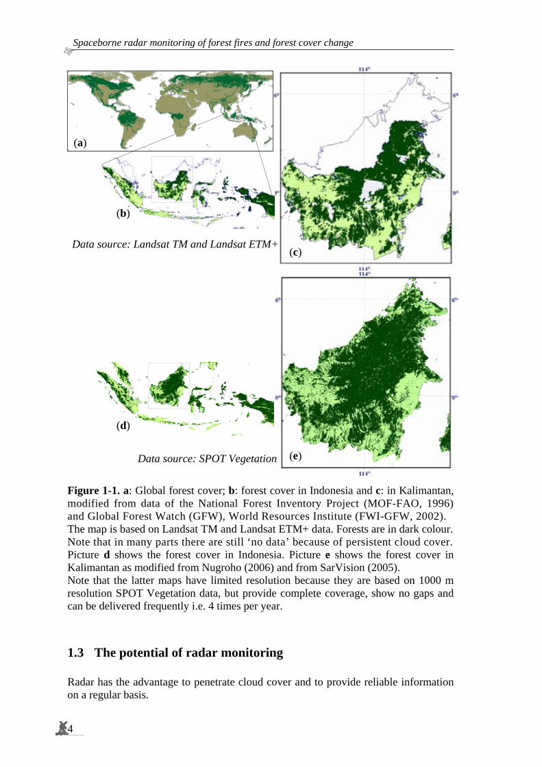
1.2 Current operational constraints in Indonesia The Indonesian Ministry of Forestry completed the National Forest Inventory (NFI) project in the year 1996 (MOF-FAO, 1996). This benchmark inventory generated important forest resources information for forest policy formulation and strategic planning at the national and provincial level. Of course, regular updates are a necessity and new satellite images should be acquired continuously in order to monitor the forests. At present the MOF has the capability and expertise to carry out forest resources monitoring at a national level. However, the current monitoring system in the MOF still depends on the availability of cloud-free optical remote sensing data. The main obstacle is that spaceborne optical images suffer too much from cloud cover. About 30 % of the forest areas in Indonesia are almost permanently covered by clouds. Statistics derived from the study of spatial and temporal distribution of cloud cover using geostationary meteorological satellites reveal that the probability of acquiring Landsat TM or SPOT images with less than 30 % cloud cover are definitely very low. For the province East Kalimantan, for example, the mean monthly probability to acquire images from Landsat with less than 50 % cloud cover is only 7 % (Gastellu-Etchegorry, 1988a, 1988b). Consequently, mapping of forest resources using optical remotely sensed data has never been completed within a reasonable time frame. In this respect, advanced spaceborne radar techniques are very promising. It is noted that the MOF currently also explores the use of SPOT-Vegetation and MODIS (Moderate Resolution Imaging Spectroradiometer) data as complementary inputs for such a monitoring system. Since these data are acquired almost daily, everywhere, the cloud problem is significantly reduced. However, with a 250 m – 1000 m pixel size, these data do not provide a high resolution. This system was introduced at MOF on the basis of the work pioneered by Nugroho (2006). Figure 1-1 compares recent results of this system with results of the NFI.
Spaceborne radar monitoring of forest fires and forest cover change
4
Figure 1-1. a: Global forest cover; b: forest cover in Indonesia and c: in Kalimantan, modified from data of the National Forest Inventory Project (MOF-FAO, 1996) and Global Forest Watch (GFW), World Resources Institute (FWI-GFW, 2002). The map is based on Landsat TM and Landsat ETM+ data. Forests are in dark colour. Note that in many parts there are still ‘no data’ because of persistent cloud cover. Picture d shows the forest cover in Indonesia. Picture e shows the forest cover in Kalimantan as modified from Nugroho (2006) and from SarVision (2005). Note that the latter maps have limited resolution because they are based on 1000 m resolution SPOT Vegetation data, but provide complete coverage, show no gaps and can be delivered frequently i.e. 4 times per year.
1.3 The potential of radar monitoring Radar has the advantage to penetrate cloud cover and to provide reliable information on a regular basis.
(c) Data source: Landsat TM and Landsat ETM+
(e) Data source: SPOT Vegetation
(b)
(d)
(a)

1. Introduction.
5
For tropical rainforests this technique has been pioneered by Bijker (1997) and Van der Sanden (1997). They used data of the first operational radar satellite for civil applications, viz. the ERS-1 SAR of the European Space Agency (ESA), which was launched in 1991. Analysis of ERS-1 SAR image time series of a colonization area in the Colombian Amazon for the period 1992 – 1994, revealed a huge potential for land cover classification and monitoring. Though areas of deforestation are well visible in single observation data, good classification results, i.e. higher than 60 % could only be obtained using a series of minimal three images capturing the seasonal dynamics (Bijker, 1997). Analysis of ERS-1 SAR data of tropical rainforests in Guyana during the same period revealed the potential of texture analysis for forest type classification and timber road detection (Van der Sanden, 1997) These early results triggered the Indonesian Ministry of Forestry in 1995 to initiate a local research project to achieve proper introduction of these new mapping and monitoring tools. This was done in co-operation with Wageningen University and the International MOF-Tropenbos Kalimantan Programme. Within this project the capabilities of advanced radar remote sensing systems for forest management and inventory should be investigated systematically and demonstrated, and staff of the Ministry should be trained (Hoekman, 1997). Initially, the main categories of application were identified as:
1. Mapping of land-use and vegetation types at different scales; 2. Forest fire monitoring (risk and damage); 3. Monitoring indicators of sustainable forest management; 4. 'Advanced' products, such as tree height or timber volume.
To support this development the so-called ESA INDonesian Radar EXperiment (INDREX) was carried out in 1996. The main element of INDREX was an airborne radar campaign carried out in Sumatra and Kalimantan by Dornier and Wageningen University under auspices of the MOF and ESA. To support analysis of the INDREX airborne radar data, additional time series of ERS-1 SAR satellite data were collected. One of the major achievements of INDREX has been the pioneering work in the area of 3D tree mapping (Hoekman & Varekamp, 2001; Varekamp & Hoekman, 2001, 2002; Hoekman et al., 2002). These achievements contributed highly to the categories 3 and 4 as mentioned above. Subsequently, this technique has been calibrated and introduced to the MOF through the work of Nugroho (2006), who systematically explored the utility of radar derived information at local, provincial and national levels within a proposed ‘executive information system’. During the past decade research activities on the development of the application of Synthetic Aperture Radar (SAR) for monitoring ecosystem processes has grown significantly. Its potential use has been categorised broadly as follows: (a) classification and detection of change in land cover; (b) estimation of woody biomass; (c) monitoring the extent and duration of inundation; and (d) monitoring other temporally-dynamic processes (Kasischke et al., 1997). It is generally recognized that to fulfil information needs, accurate mapping and monitoring is required at different spatial and time scales.

Spaceborne radar monitoring of forest fires and forest cover change
6
There is also wide consensus in the radar community that severe cloud cover often prevents the acquisition of optical remote sensing data, thus making the use of satellite radar remote sensing necessary for monitoring applications. On the other hand, radar data may provide different or additional information, thus making (additional) use of radar data (both spaceborne and airborne) an interesting choice, particularly for less timeliness-demanding applications such as inventory (Hoekman, 2001). In recent years many research activities focused on the use of SAR to study tropical rainforest. At continental scale mosaics of all tropical rainforests have been created using JERS-1 SAR images (Siqueira et al., 2000; Rosenqvist et al., 2000; Sgrenzaroli, 2004) and, for Africa, using ERS-1 SAR (De Grandi et al., 1999). At a larger scale researchers have focused their studies on the development of inversion algorithms, segmentation and classification techniques for polarimetric and interferometric SAR images and created a variety of types of tropical rainforest classifications, for example using texture (Van der Sanden, 1997; Oliver, 2000) and mapping individual trees (Varekamp, 2002). Mapping tropical rainforest types and its biophysical characteristics with airborne SAR (AirSAR) was explored for the Amazon (Hoekman and Quiñones, 2002; Quiñones, 2002). Prakoso (2006) shows the latter type of application, using AirSAR and TOPSAR airborne radar data collected during the NASA PacRim-II campaign executed in 2000, was recently studied for Kalimantan.
1.4 Study approach Currently, monitoring at the national level by MOF is executed by using its multi-temporal satellite remote sensing database, comprising Landsat MSS, Landsat TM and ETM+, and is limited to the spatial scale of 1:250,000. Though, in principle, these data are useful, severe cloud cover prevents a yearly update. Considering the fact that there are still areas that have never been mapped in this way, clearly another approach should be considered for forest monitoring by MOF (Hoekman, 1997; Wooding, 1999). Van der Sanden (1997) describes forest resource monitoring as the process of continuously knowing the state of the forest environment and the changes that have been and are taking place. Hence, it requires collecting, processing and presenting successive data on the location, extent and nature of changes. In order to plan and guide changes it is also important to gather information on the cause and rate of change. Reliable monitoring of forest resources is feasible only if the starting point is well described by means of forest resource assessment. For monitoring purposes additional time series data are imperative. Wilkie and Finn (1996) illustrate that natural resources monitoring should allow observing the changes that ecosystems are undergoing. Data are needed, which can be obtained frequently over long time periods. Evidently the availability of historical data for monitoring is required to achieve fine recognition of the land cover change processes, in particular in those regions where significant changes happen because of forest fire, flooding, logging, land clearing or plantation. Understanding the behavioural characteristic of (wild)-fires, for example, and how they spread through the various vegetation types and terrain, are a major concern within the MOF.
1. Introduction.
7
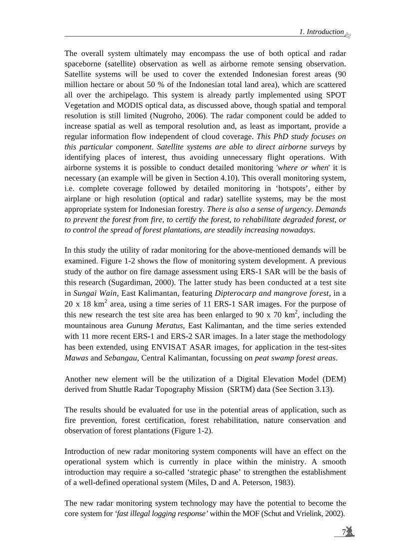
The overall system ultimately may encompass the use of both optical and radar spaceborne (satellite) observation as well as airborne remote sensing observation. Satellite systems will be used to cover the extended Indonesian forest areas (90 million hectare or about 50 % of the Indonesian total land area), which are scattered all over the archipelago. This system is already partly implemented using SPOT Vegetation and MODIS optical data, as discussed above, though spatial and temporal resolution is still limited (Nugroho, 2006). The radar component could be added to increase spatial as well as temporal resolution and, as least as important, provide a regular information flow independent of cloud coverage. This PhD study focuses on this particular component. Satellite systems are able to direct airborne surveys by identifying places of interest, thus avoiding unnecessary flight operations. With airborne systems it is possible to conduct detailed monitoring 'where or when' it is necessary (an example will be given in Section 4.10). This overall monitoring system, i.e. complete coverage followed by detailed monitoring in ‘hotspots’, either by airplane or high resolution (optical and radar) satellite systems, may be the most appropriate system for Indonesian forestry. There is also a sense of urgency. Demands to prevent the forest from fire, to certify the forest, to rehabilitate degraded forest, or to control the spread of forest plantations, are steadily increasing nowadays.
In this study the utility of radar monitoring for the above-mentioned demands will be examined. Figure 1-2 shows the flow of monitoring system development. A previous study of the author on fire damage assessment using ERS-1 SAR will be the basis of this research (Sugardiman, 2000). The latter study has been conducted at a test site in Sungai Wain, East Kalimantan, featuring Dipterocarp and mangrove forest, in a 20 x 18 km2 area, using a time series of 11 ERS-1 SAR images. For the purpose of this new research the test site area has been enlarged to 90 x 70 km2, including the mountainous area Gunung Meratus, East Kalimantan, and the time series extended with 11 more recent ERS-1 and ERS-2 SAR images. In a later stage the methodology has been extended, using ENVISAT ASAR images, for application in the test-sites Mawas and Sebangau, Central Kalimantan, focussing on peat swamp forest areas. Another new element will be the utilization of a Digital Elevation Model (DEM) derived from Shuttle Radar Topography Mission (SRTM) data (See Section 3.13). The results should be evaluated for use in the potential areas of application, such as fire prevention, forest certification, forest rehabilitation, nature conservation and observation of forest plantations (Figure 1-2). Introduction of new radar monitoring system components will have an effect on the operational system which is currently in place within the ministry. A smooth introduction may require a so-called ‘strategic phase’ to strengthen the establishment of a well-defined operational system (Miles, D and A. Peterson, 1983). The new radar monitoring system technology may have the potential to become the core system for ‘fast illegal logging response’ within the MOF (Schut and Vrielink, 2002).

Spaceborne radar monitoring of forest fires and forest cover change
8
The research will be concluded by describing the potential use of the current state-of-the-art radar system, its relevance for Indonesian forestry monitoring activities and the impact of future remote sensing and forestry application developments.
Figure 1-2. SAR monitoring system development approach within this study.
1.5 Study objectives The aim of this research is to investigate the use of spaceborne radar remote sensing for forestry monitoring activities, to develop suitable procedures to extract information from images and to incorporate these methods to produce regular updates of land (forest) cover maps at national and/or regional / provincial level. The following research questions can be addressed:
• What are the current methodologies available for forest resources monitoring? • What are the restrictions and operational constraints of the current methodologies? • How can spaceborne radar technology support the development of a national
system for forest monitoring? • Should the methodology be adjusted for specific potential areas of application? • Is the methodology practical to handle extensive data sets and vast areas? • What is the strategy for introducing the new radar methodology into the
current routine of the MOF?
Evaluate
New data sources: • ERS-SAR • SRTM DEM • ENVISAT ASAR
Current status: • Fire damage assessment • Landsat monitoring
New Proposed SARMonitoring System
New test site
New Improved SARMonitoring System
Potential area of application:
• Fire prevention • Forest rehabilitation • Forest certification • Forest plantation • Nature conservation
Process DocumentMulti
Document SubroutineInput/Output
StoredData
Legend:
1. Introduction.
9
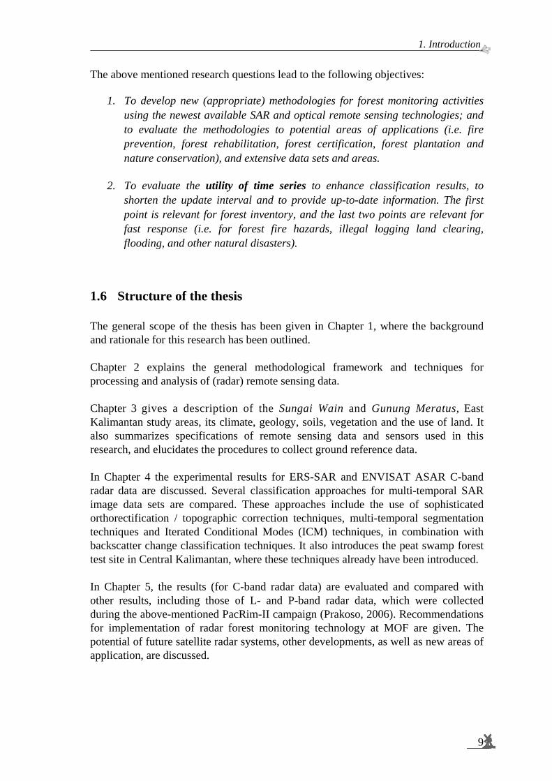
The above mentioned research questions lead to the following objectives:
1. To develop new (appropriate) methodologies for forest monitoring activities using the newest available SAR and optical remote sensing technologies; and to evaluate the methodologies to potential areas of applications (i.e. fire prevention, forest rehabilitation, forest certification, forest plantation and nature conservation), and extensive data sets and areas.
2. To evaluate the utility of time series to enhance classification results, to
shorten the update interval and to provide up-to-date information. The first point is relevant for forest inventory, and the last two points are relevant for fast response (i.e. for forest fire hazards, illegal logging land clearing, flooding, and other natural disasters).
1.6 Structure of the thesis The general scope of the thesis has been given in Chapter 1, where the background and rationale for this research has been outlined. Chapter 2 explains the general methodological framework and techniques for processing and analysis of (radar) remote sensing data. Chapter 3 gives a description of the Sungai Wain and Gunung Meratus, East Kalimantan study areas, its climate, geology, soils, vegetation and the use of land. It also summarizes specifications of remote sensing data and sensors used in this research, and elucidates the procedures to collect ground reference data. In Chapter 4 the experimental results for ERS-SAR and ENVISAT ASAR C-band radar data are discussed. Several classification approaches for multi-temporal SAR image data sets are compared. These approaches include the use of sophisticated orthorectification / topographic correction techniques, multi-temporal segmentation techniques and Iterated Conditional Modes (ICM) techniques, in combination with backscatter change classification techniques. It also introduces the peat swamp forest test site in Central Kalimantan, where these techniques already have been introduced. In Chapter 5, the results (for C-band radar data) are evaluated and compared with other results, including those of L- and P-band radar data, which were collected during the above-mentioned PacRim-II campaign (Prakoso, 2006). Recommendations for implementation of radar forest monitoring technology at MOF are given. The potential of future satellite radar systems, other developments, as well as new areas of application, are discussed.

C h a p t e r
2 ______________________________________________
2 MULTI-TEMPORAL SAR CLASSIFICATION WITH SLOPE CORRECTION AND
TEXTURAL ANALYSIS This chapter describes methods and techniques used in this thesis to extract, to process and to analyze radar data.
2.1 Multi-temporal Synthetic Aperture Radar images A major advantage of satellite Synthetic Aperture Radar (SAR) is its ability to acquire precisely calibrated images, which are unaffected by clouds (Quegan and Le Toan, 1998). This means that time series of accurate measurements are available for environmental monitoring and applications. Measurements that can be used include the temporal change in the backscattering coefficient and, under special time interval and baseline conditions, interferometric coherence and phase difference. For operational applications, however, the preferred information is that from changes in the backscattering coefficient, since these are routinely available under almost all conditions for a satellite SAR. For mapping purposes, this requires making use of the differing temporal signatures of different land cover types. Important examples are found in forestry and agriculture. Forestry exploits the low temporal change of forests compared to other cover types (Grover et al., 1998; Le Toan et al., 1995 in Quegan and Le Toan, 1998). By contrast, rice mapping relies on the high temporal change associated with flooded rice (Le Toan et al., 1997). Proper processing of multi-temporal SAR data can significantly circumvent problems associated with radar speckle. Since radar signals are coherent, the radar returns from scattering elements within a resolution cell interfere. These interference patterns are often regarded as a kind of noise, and give the image a ‘grainy’ appearance. Techniques to reduce the noise generally also reduce the spatial resolution. However, when a series of images is available, for example, images that are collected within a very short period, they could be averaged to reduce speckle. More interestingly, when large time-series over a long period are available and proper temporal signatures (which are characteristic for the temporal change in backscatter for specific land classes) are extracted, the effect of speckle on classification accuracy can be strongly reduced by signal processing techniques. Since land cover classes change with time, the major problem of supervised classification of multi-temporal images is that the training areas (regions of interest or ROI’s) have to be repeatedly selected for each image within the (group) of multi-temporal remote sensing data (Schowengerdt, 2007).
11
Spaceborne radar monitoring of forest fires and forest cover change
12
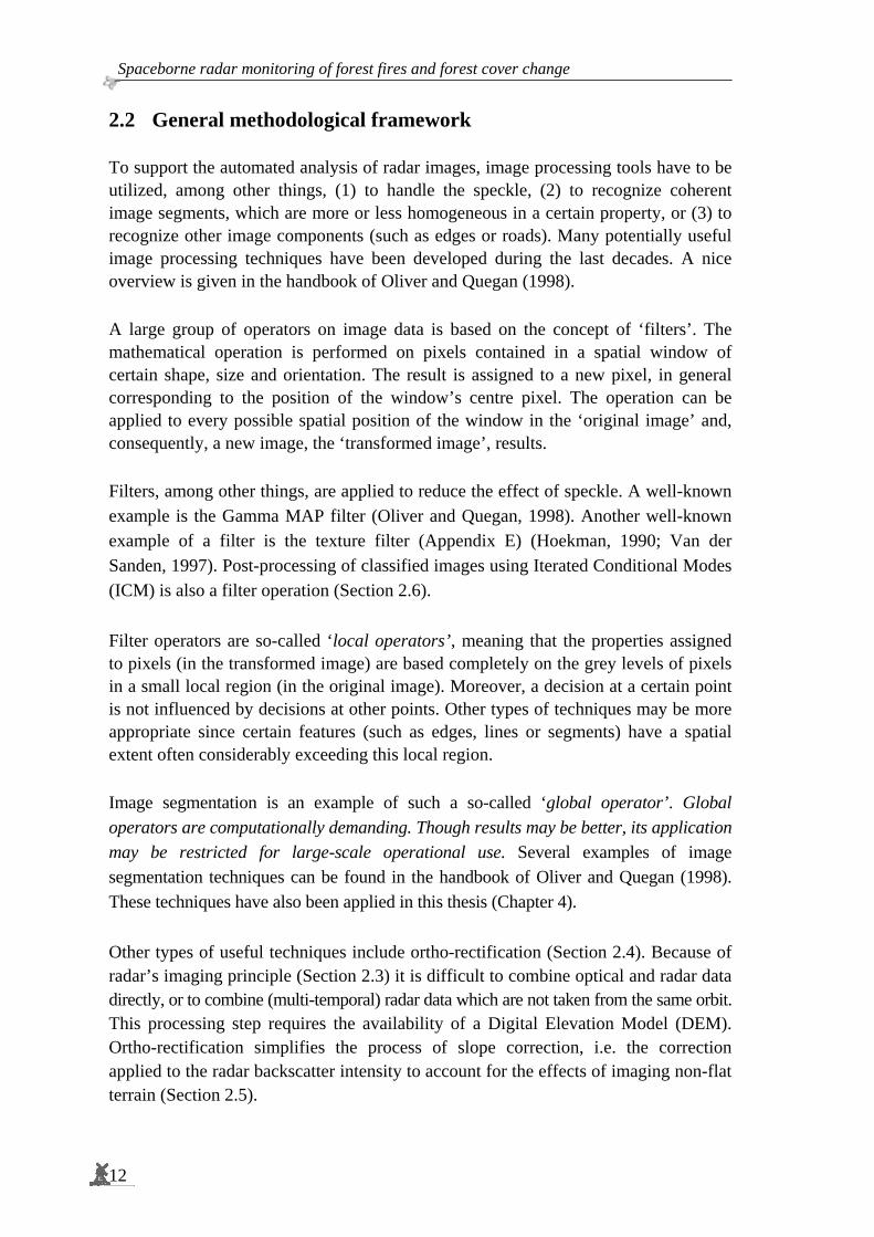
2.2 General methodological framework To support the automated analysis of radar images, image processing tools have to be utilized, among other things, (1) to handle the speckle, (2) to recognize coherent image segments, which are more or less homogeneous in a certain property, or (3) to recognize other image components (such as edges or roads). Many potentially useful image processing techniques have been developed during the last decades. A nice overview is given in the handbook of Oliver and Quegan (1998). A large group of operators on image data is based on the concept of ‘filters’. The mathematical operation is performed on pixels contained in a spatial window of certain shape, size and orientation. The result is assigned to a new pixel, in general corresponding to the position of the window’s centre pixel. The operation can be applied to every possible spatial position of the window in the ‘original image’ and, consequently, a new image, the ‘transformed image’, results. Filters, among other things, are applied to reduce the effect of speckle. A well-known example is the Gamma MAP filter (Oliver and Quegan, 1998). Another well-known example of a filter is the texture filter (Appendix E) (Hoekman, 1990; Van der Sanden, 1997). Post-processing of classified images using Iterated Conditional Modes (ICM) is also a filter operation (Section 2.6). Filter operators are so-called ‘local operators’, meaning that the properties assigned to pixels (in the transformed image) are based completely on the grey levels of pixels in a small local region (in the original image). Moreover, a decision at a certain point is not influenced by decisions at other points. Other types of techniques may be more appropriate since certain features (such as edges, lines or segments) have a spatial extent often considerably exceeding this local region. Image segmentation is an example of such a so-called ‘global operator’. Global operators are computationally demanding. Though results may be better, its application may be restricted for large-scale operational use. Several examples of image segmentation techniques can be found in the handbook of Oliver and Quegan (1998). These techniques have also been applied in this thesis (Chapter 4). Other types of useful techniques include ortho-rectification (Section 2.4). Because of radar’s imaging principle (Section 2.3) it is difficult to combine optical and radar data directly, or to combine (multi-temporal) radar data which are not taken from the same orbit. This processing step requires the availability of a Digital Elevation Model (DEM). Ortho-rectification simplifies the process of slope correction, i.e. the correction applied to the radar backscatter intensity to account for the effects of imaging non-flat terrain (Section 2.5).
2. Multi-temporal SAR classification with slope correction and textural analysis.
13
Furthermore, supervised classification techniques rely on training data. The classification itself may be performed using standard Maximum Likelihood approaches (ML) (Appendix B), optionally followed by ICM or Markov Random Field (MRF) filtering. Good results can only be obtained with reliable ground reference data. Extraction of training data often is the starting point of data processing. The approaches adopted in this thesis are outlined schematically in Figure 2-1. After selection of the area of interest, ERS-SAR images and the corresponding DEM derived from the Shuttle Radar Topography Mission can be selected. The DEM can be used to bring the calibrated ERS-SAR images in geometric registration and to derive an extra image showing slope angles. After pre-processing steps such as speckle and/or texture filtering, optional image segmentation and the optional slope correction, the image can be classified using pre-selected image parts (Regions Of Interest or ROI's) as training data. The ICM filter can be applied as a post-processing step.

Spaceborne radar monitoring of forest fires and forest cover change
14
Figure 2-1. Flowchart of the multi-temporal classification.
PRI Images
Shuttle Radar Topography Mission
Data
ESA
Database
NASA
Database
Ortho-rectification
Slope correction
Ortho-rectified Images
Slope corrected Images
Slope
Aspect
Contour
ParametersExtraction
Maximum Likelihood Classification
Ortho-rectifiedLand Cover Map
Slope correctedLand Cover Map
Comparison
Evaluation Results
Georeference
Calibration
Pre- Processing
Texture Analysis
Pre- Classification
Region of Interest
Selection of ERS PRI Images
Iterated Conditional Modes
Definition of Area and Time of Interest
Digital Elevation Model

2. Multi-temporal SAR classification with slope correction and textural analysis.
15
2.3 The imaging principle Radar imaging is based on the principle of projecting range differences. Such in contrast to passive systems where imaging is based on the projection of angular differences. Images of terrain with steep slopes can show considerable geometric distortion because of the so-called radar parallaxes: foreshortening and layover. Some parts of the terrain may not be illuminated at all and show black in the image: the so-called radar shadow. These effects are illustrated in Figure 2-2. Certain subtle geologic features may show up well in such images. For other applications it can be a disadvantage and map projection, using a Digital Elevation Model (DEM), may be a necessary additional processing step.
Figure 2-2. Effects of parallax and shadow in radar imaging. Three pyramids are observed sideways from an aircraft. The upper image shows a slant range radar image, the middle image a geometrically corrected ground range radar image and the lower image a geometrically corrected optical scanner image. As opposed to the optical imaging, radar imaging shows (1) that the tops of the pyramids are displaced towards the sensor and (2) the shadows are behind the pyramids as seen from the sensor, and not as seen from the Sun.
slant range radar image
geometrically corrected ground range radar image
geometrically corrected optical scanner image
Spaceborne radar monitoring of forest fires and forest cover change
16
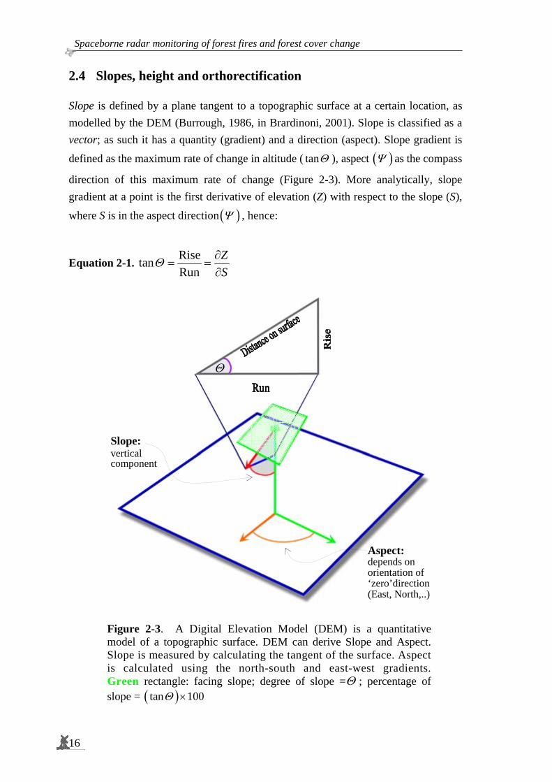
2.4 Slopes, height and orthorectification Slope is defined by a plane tangent to a topographic surface at a certain location, as modelled by the DEM (Burrough, 1986, in Brardinoni, 2001). Slope is classified as a vector; as such it has a quantity (gradient) and a direction (aspect). Slope gradient is
defined as the maximum rate of change in altitude ( tanΘ ), aspect ( )Ψ as the compass
direction of this maximum rate of change (Figure 2-3). More analytically, slope gradient at a point is the first derivative of elevation (Z) with respect to the slope (S),
where S is in the aspect direction ( )Ψ , hence:
Equation 2-1. RisetanRun
ZS
Θ ∂= =
∂
Figure 2-3. A Digital Elevation Model (DEM) is a quantitative model of a topographic surface. DEM can derive Slope and Aspect. Slope is measured by calculating the tangent of the surface. Aspect is calculated using the north-south and east-west gradients. Green rectangle: facing slope; degree of slope =Θ ; percentage of slope = ( )tan 100Θ ×
Θ
Slope: vertical component
Aspect: depends on orientation of ‘zero’direction (East, North,..)
2. Multi-temporal SAR classification with slope correction and textural analysis.
17
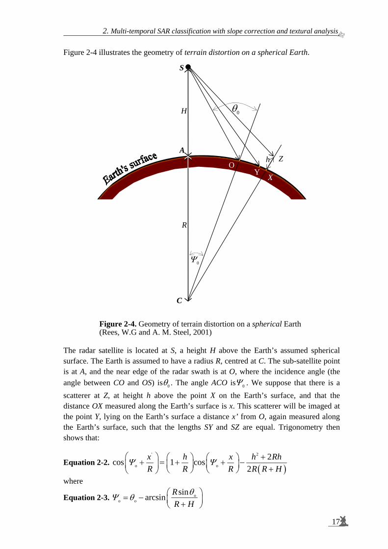
Figure 2-4 illustrates the geometry of terrain distortion on a spherical Earth.
Figure 2-4. Geometry of terrain distortion on a spherical Earth (Rees, W.G and A. M. Steel, 2001)
The radar satellite is located at S, a height H above the Earth’s assumed spherical surface. The Earth is assumed to have a radius R, centred at C. The sub-satellite point is at A, and the near edge of the radar swath is at O, where the incidence angle (the angle between CO and OS) is 0θ . The angle ACO is 0Ψ . We suppose that there is a scatterer at Z, at height h above the point X on the Earth’s surface, and that the distance OX measured along the Earth’s surface is x. This scatterer will be imaged at the point Y, lying on the Earth’s surface a distance x’ from O, again measured along the Earth’s surface, such that the lengths SY and SZ are equal. Trigonometry then shows that:
Equation 2-2. ( )
' 2
o o
2cos 1 cos2
x h x h RhR R R R R H
Ψ Ψ +⎛ ⎞ ⎛ ⎞ ⎛ ⎞+ = + + −⎜ ⎟ ⎜ ⎟⎜ ⎟ +⎝ ⎠ ⎝ ⎠⎝ ⎠
where
Equation 2-3. oo o
sinarcsin RR H
θΨ θ ⎛ ⎞= − ⎜ ⎟+⎝ ⎠
0θ
0Ψ
Z h
S
H
A
R
C
OY
X
Spaceborne radar monitoring of forest fires and forest cover change
18
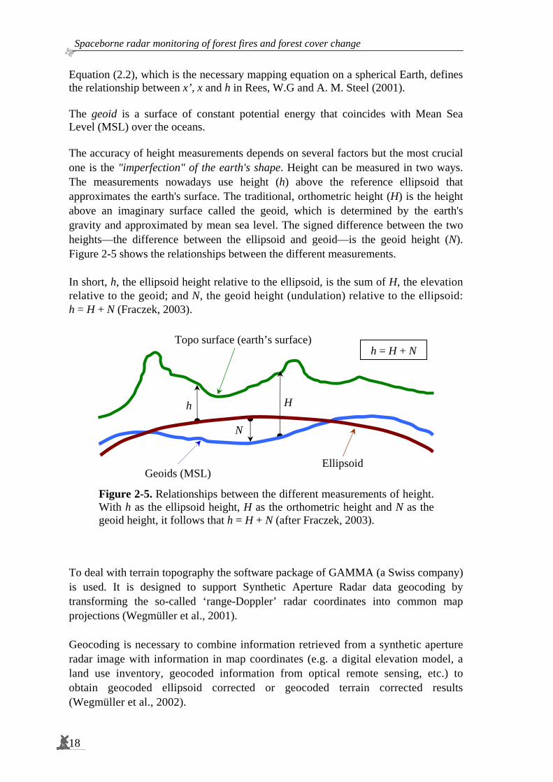
Equation (2.2), which is the necessary mapping equation on a spherical Earth, defines the relationship between x’, x and h in Rees, W.G and A. M. Steel (2001). The geoid is a surface of constant potential energy that coincides with Mean Sea Level (MSL) over the oceans. The accuracy of height measurements depends on several factors but the most crucial one is the "imperfection" of the earth's shape. Height can be measured in two ways. The measurements nowadays use height (h) above the reference ellipsoid that approximates the earth's surface. The traditional, orthometric height (H) is the height above an imaginary surface called the geoid, which is determined by the earth's gravity and approximated by mean sea level. The signed difference between the two heights—the difference between the ellipsoid and geoid—is the geoid height (N). Figure 2-5 shows the relationships between the different measurements. In short, h, the ellipsoid height relative to the ellipsoid, is the sum of H, the elevation relative to the geoid; and N, the geoid height (undulation) relative to the ellipsoid: h = H + N (Fraczek, 2003).
Figure 2-5. Relationships between the different measurements of height. With h as the ellipsoid height, H as the orthometric height and N as the geoid height, it follows that h = H + N (after Fraczek, 2003).
To deal with terrain topography the software package of GAMMA (a Swiss company) is used. It is designed to support Synthetic Aperture Radar data geocoding by transforming the so-called ‘range-Doppler’ radar coordinates into common map projections (Wegmüller et al., 2001). Geocoding is necessary to combine information retrieved from a synthetic aperture radar image with information in map coordinates (e.g. a digital elevation model, a land use inventory, geocoded information from optical remote sensing, etc.) to obtain geocoded ellipsoid corrected or geocoded terrain corrected results (Wegmüller et al., 2002).
Ellipsoid Geoids (MSL)
h
N
H
Topo surface (earth’s surface)h = H + N

2. Multi-temporal SAR classification with slope correction and textural analysis.
19
2.5 Slope correction model Bayer et al (1991) explain why Synthetic Aperture Radar (SAR) images of undulated terrain show significant brightness variations caused by the side-looking technique of the sensor. These brightness variations depend on relief slope and relief aspect relative to the illumination direction. Holben and Justice (1981) named this effect "the topographic effect", while Domik et al., 1984 in Bayer et al (1991) called it "the topographic component" of the information content of SAR images. It is well known that airborne Synthetic Aperture Radar (SAR) imaging is based on the principle of range differences between the objects and the sensor for a certain scan line. Because of the imaging mechanism of radar signals, small relief differences can be perceived well, notably at small grazing angles grθ .
Figure 2-6. For an opaque isotropic volume scatterer, γ being the differential radar cross section, 0
icosγ σ θ= , is independent of the grazing angle grθ (cases a and b) and dependent on slope α (case c) (after Hoekman, 1990).
For an opaque isotropic volume scatterer, γ (the differential radar cross-section,
0icosγ σ θ= , with σ0 as the radar cross-section and iθ as the incidence angle) does
not depend on grazing angle, but will depend on the slope of the vegetation surface (Figure 2-6). Always, and therefore also for the three cases shown in this Figure, the ratio between intercepted power and the re-radiated power is the same for every resolution cell. Processing algorithms (which are based on the geometric optics approximation) to computeγ , however, start from the assumption that the terrain is flat, and hence assume the intercepted power is proportional to grtanθ .
cγ
αbθ
aθ
aθ
aγ
a cbγ γ γ= ≠
bγ
bθ
(a) (b)
(c)

Spaceborne radar monitoring of forest fires and forest cover change
20
In fact it is proportional to ( )grtan θ α+ , where α is the angle of slope in range
direction which can be derived from InSAR data. The value of γ in the processed image is therefore related to the value of fγ , for an identical object with the upper surface oriented parallel to the horizontal plane, as follows:
Equation 2-4. ( )gr
fgr
tantanθ α
γ γθ+
=
Figure 2-7 shows this relation in graphical form. The ratio fγ γ (or 0 0
fσ σ ) is shown at the dB scale as function of grazing angle and for several slope angles. It can be concluded that, if this mechanism applies, small slopes observed at very small or very large grazing angles have strong effects on the backscatter level. Furthermore, it can be shown that the effects of canopy surface undulations average out for this model in the sense that the (linear) average of γ , for any area within a perimeter located at a horizontal plane and not showing radar shadow, is independent of the degree and location of slopes (after Hoekman, 1990).
0 10 20 30 40 50 60 70 80 90−5
−4
−3
−2
−1
0
1
2
3
4
5
θgr
Δ dBα=+5
α=+3
α=+1
α=−5
α=−3
α=−1
Figure 2-7. Effect of canopy undulations if an opaque isotropic volume scatter mechanism applies. Changes inγ level as a function of grazing angle grθ and slope angleα are shown (after Hoekman, 1990).
5α = +
3α = +
1α = +
5α = −
3α = −
1α = −
grθ
dBΔ
2. Multi-temporal SAR classification with slope correction and textural analysis.
21
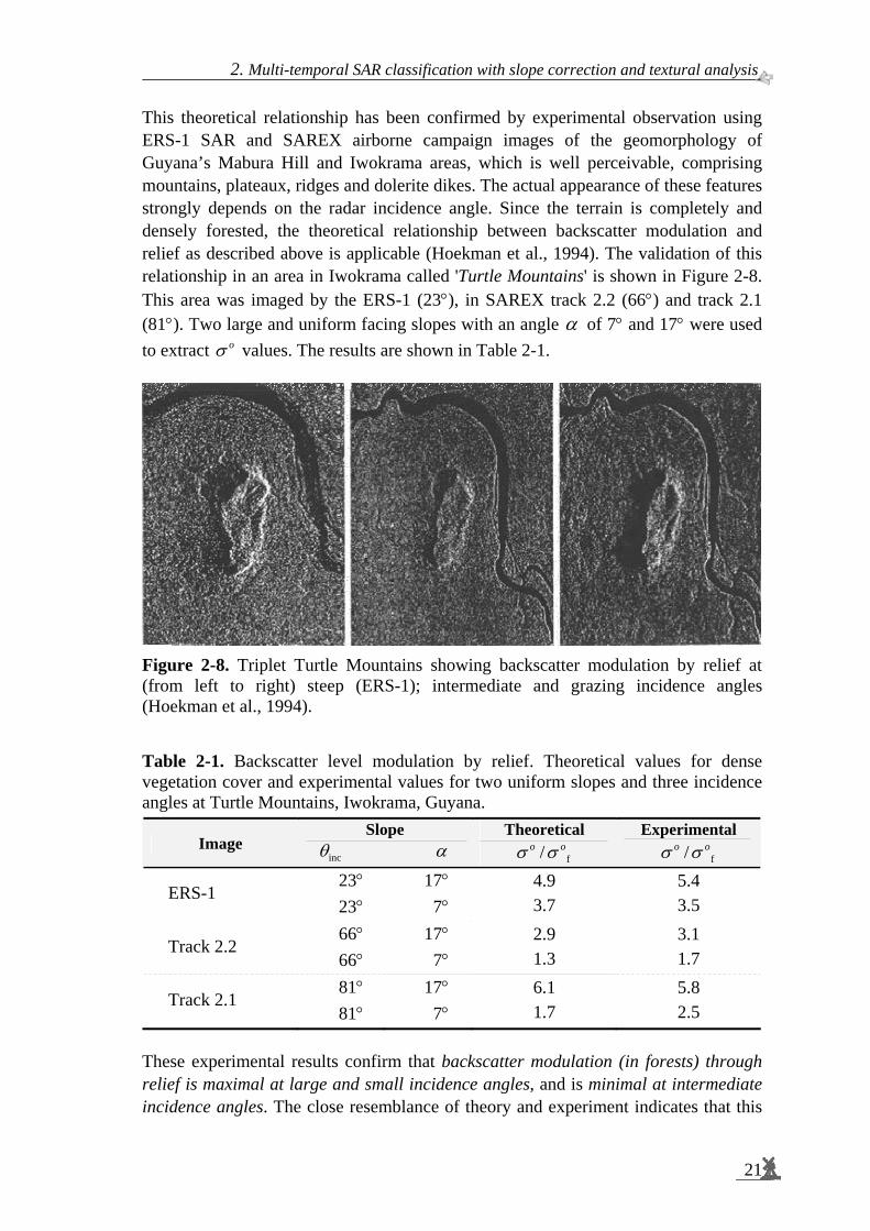
This theoretical relationship has been confirmed by experimental observation using ERS-1 SAR and SAREX airborne campaign images of the geomorphology of Guyana’s Mabura Hill and Iwokrama areas, which is well perceivable, comprising mountains, plateaux, ridges and dolerite dikes. The actual appearance of these features strongly depends on the radar incidence angle. Since the terrain is completely and densely forested, the theoretical relationship between backscatter modulation and relief as described above is applicable (Hoekman et al., 1994). The validation of this relationship in an area in Iwokrama called 'Turtle Mountains' is shown in Figure 2-8. This area was imaged by the ERS-1 (23°), in SAREX track 2.2 (66°) and track 2.1 (81°). Two large and uniform facing slopes with an angle α of 7° and 17° were used to extract oσ values. The results are shown in Table 2-1.
Figure 2-8. Triplet Turtle Mountains showing backscatter modulation by relief at (from left to right) steep (ERS-1); intermediate and grazing incidence angles (Hoekman et al., 1994). Table 2-1. Backscatter level modulation by relief. Theoretical values for dense vegetation cover and experimental values for two uniform slopes and three incidence angles at Turtle Mountains, Iwokrama, Guyana.
Image Slope
incθ α Theoretical
f/o oσ σ Experimental
f/o oσ σ
ERS-1 23° 23°
17° 7°
4.9 3.7
5.4 3.5
Track 2.2 66° 66°
17° 7°
2.9 1.3
3.1 1.7
Track 2.1 81° 81°
17° 7°
6.1 1.7
5.8 2.5
These experimental results confirm that backscatter modulation (in forests) through relief is maximal at large and small incidence angles, and is minimal at intermediate incidence angles. The close resemblance of theory and experiment indicates that this
Spaceborne radar monitoring of forest fires and forest cover change
22
simple methodology can be used for slope correction, and may be useful to quantify slope angles in support of the preparation of Digital Elevation Models (DEM). In case a DEM is available, the theory can be applied to decompose the backscatter signal in a part that can be contributed to relief modulation and a part related to cover type. In this way, changes in terrain cover may be recognized more easily. Alternative theoretical methodologies for the radiometric slope correction with more complex approximations can be found in the literature (Ulander, 1996; Castel et al., 2001). These methods are also based on local incidence angle and terrain slope tilt angle, but include the terrain slope aspect angle in addition.
2.6 Interferometric and polarimetric radar Advanced radar systems such as polarimetric and interferometric radar systems differ from conventional SAR systems. For comparison the conventional SAR system is schematically depicted in Figure 2-9 (top left). Here an antenna transmits pulses with a time interval Δt and the same antenna records echoes in the period between transmissions. An interferometric SAR system uses an additional receiving antenna separated by the so-called baseline distance B (Figure 2-9, bottom left). Since the path of the reflected pulse has to travel back to the transmitting antenna in general differs from the path the reflected pulse has to travel back to the non-transmitting antenna, a phase difference arises between the two radar echoes. Since this phase difference can be related to the direction of the echoes, and the distance of the reflecting object can be computed from the time elapsed between transmission and reception of the pulse, the three dimensional position of the reflecting object can be determined. This technique is used to create three-dimensional ‘tree maps’ in Prakoso and Suryokusumo, 2000. A polarimetric radar system is shown in Figure 2-9 (right). In this system a vertically polarised wave is transmitted (the wave has a short duration and, depending on context, is sometimes called a pulse, like above). When reflecting from an object a wave can change polarisation and this change is measured by comparing the vertical polarised part of the reflection measured by the (transmitting) vertically polarised antenna with the horizontally polarised part of the reflection measured by a second, horizontally polarised, antenna. Next a horizontal polarised wave is transmitted and, again, horizontally and vertically polarised parts of the reflected wave are measured. The vertically and horizontally transmitted waves are interleaved, resulting in four measurements of backscatter in the time interval Δt. Through a process of polarisation synthesis it is possible to determine the backscatter properties of an object for any polarisation.

2. Multi-temporal SAR classification with slope correction and textural analysis.
23
Figure 2-9. Antennae configurations of advanced SAR systems. The arrow indicates the flight direction. A: Conventional SAR with single antenna for transmission and reception. B: Interferometric (Across-Track) SAR with additional antenna for reception. C: Polarimetric SAR with two polarised antennae for transmission (V and H) and reception VV, HV, VH and HH).
2.7 Iterated Conditional Modes The likelihood of a pixel i belonging to class c, lhi,c is based on the (multi-frequency)
radar signal properties in terms of intensities, phases and coherences (See also Hoekman and Quiñones, 2002). The classification of a pixel simply is the selection of the class for which lhi,c is the highest (the Maximum Likelihood or ML solution).
In the Iterated Conditional Modes (ICM) method the likelihood lhi,c is modified to
mlhi,c by multiplication with a conditional probability ( )exp β i,cu , where i,cu is the
current number of neighbours of pixel i having class c, and β is a parameter determining the relative importance of neighbourhood information. In the approach adopted here the eight surrounding pixels form the neighbourhood. The following notation for the neighbourhood of pixel i is adopted:
1 2 3
4 i 5
6 7 8
( )120t + n + Δt
0t + nΔt
0t + nΔt
0t + nΔt
A
B
SAR
InSAR (XTI)
POLSAR
C
Spaceborne radar monitoring of forest fires and forest cover change
24
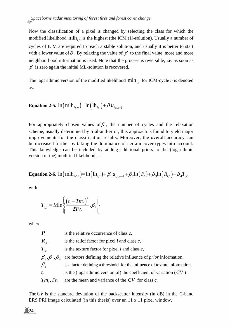
Now the classification of a pixel is changed by selecting the class for which the modified likelihood mlhi,c is the highest (the ICM (1)-solution). Usually a number of
cycles of ICM are required to reach a stable solution, and usually it is better to start with a lower value of β . By relaxing the value of β to the final value, more and more neighbourhood information is used. Note that the process is reversible, i.e. as soon as β is zero again the initial ML-solution is recovered. The logarithmic version of the modified likelihood mlhi,c for ICM-cycle n is denoted as: Equation 2-5. ( ) ( ) 1ln mlh ln lh β −= +i,c,n i,c i,c,nu
For appropriately chosen values of β , the number of cycles and the relaxation scheme, usually determined by trial-and-error, this approach is found to yield major improvements for the classification results. Moreover, the overall accuracy can be increased further by taking the dominance of certain cover types into account. This knowledge can be included by adding additional priors to the (logarithmic version of the) modified likelihood as: Equation 2-6. ( ) ( ) ( ) ( )1 1 2 3 4ln mlh ln lh ln lnci,c,n i,c i,c i,ci,c,nu P R Tβ β β β−= + + + −
with
( )2c
Ti,cc
Min ,2
β⎧ ⎫⎪ ⎪⎨ ⎬⎪ ⎪⎩ ⎭
−= it Tm
TTv
where
cP is the relative occurrence of class c,
i,cR is the relief factor for pixel i and class c,
i,cT is the texture factor for pixel i and class c,
2 3 4, ,β β β are factors defining the relative influence of prior information,
Tβ is a factor defining a threshold for the influence of texture information,
it is the (logarithmic version of) the coefficient of variation (CV ) ,c cTm Tv are the mean and variance of the CV for class c.
TheCV is the standard deviation of the backscatter intensity (in dB) in the C-band ERS PRI image calculated (in this thesis) over an 11 x 11 pixel window.
2. Multi-temporal SAR classification with slope correction and textural analysis.
25
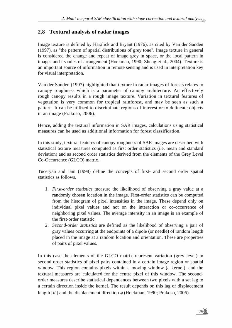
2.8 Textural analysis of radar images Image texture is defined by Haralick and Bryant (1976), as cited by Van der Sanden (1997), as "the pattern of spatial distributions of grey tone". Image texture in general is considered the change and repeat of image grey in space, or the local pattern in images and its rules of arrangement (Hoekman, 1990; Zheng et al., 2004). Texture is an important source of information in remote sensing and is used in interpretation key for visual interpretation. Van der Sanden (1997) highlighted that texture in radar images of forests relates to canopy roughness which is a parameter of canopy architecture. An effectively rough canopy results in a rough image texture. Variation in textural features of vegetation is very common for tropical rainforest, and may be seen as such a pattern. It can be utilized to discriminate regions of interest or to delineate objects in an image (Prakoso, 2006). Hence, adding the textural information in SAR images, calculations using statistical measures can be used as additional information for forest classification. In this study, textural features of canopy roughness of SAR images are described with statistical texture measures computed as first order statistics (i.e. mean and standard deviation) and as second order statistics derived from the elements of the Grey Level Co-Occurrence (GLCO) matrix. Tuceryan and Jain (1998) define the concepts of first- and second order spatial statistics as follows.
1. First-order statistics measure the likelihood of observing a gray value at a randomly chosen location in the image. First-order statistics can be computed from the histogram of pixel intensities in the image. These depend only on individual pixel values and not on the interaction or co-occurrence of neighboring pixel values. The average intensity in an image is an example of the first-order statistic.
2. Second-order statistics are defined as the likelihood of observing a pair of gray values occurring at the endpoints of a dipole (or needle) of random length placed in the image at a random location and orientation. These are properties of pairs of pixel values.
In this case the elements of the GLCO matrix represent variation (grey level) in second-order statistics of pixel pairs contained in a certain image region or spatial window. This region contains pixels within a moving window (a kernel), and the textural measures are calculated for the centre pixel of this window. The second-order measures describe statistical dependences between two pixels with a set lag to a certain direction inside the kernel. The result depends on this lag or displacement length | d | and the displacement direction φ (Hoekman, 1990; Prakoso, 2006).

Spaceborne radar monitoring of forest fires and forest cover change
26
It can be summarized that a grey-level co-occurrence matrix is the two-dimensional matrix of joint probabilities 2
, ( , )dp i jφ of pairs of pixels, separated by a distance d
in a given direction φ. Further information on textural features derived from the GLCO matrix can be found in Appendix E. In this study, textural analysis has been applied as additional information layers in multi-temporal classification as shown in Figure 2-1. Textural features were calculated on ortho-rectified and slope corrected images. The evaluation of the utility of texture was performed by comparing the classification result of ortho-rectified and slope corrected images with textural feature layers with the classification result of the ortho-rectified and slope corrected images without textural feature layers.
Figure 2-10. Evaluation of the utility of textural features by comparing the classification results of ortho-rectified and slope corrected images with and without additional textural feature information layers (See also Figure 2-1 and Appendix E).
Ortho-rectified and Slope corrected Images
Comparison
Evaluation Results
Textural Analysis
GLCO-Contrast GLCO-Correlation
Ortho-rectified andSlope corrected Imageswith Textural Analysis

2. Multi-temporal SAR classification with slope correction and textural analysis.
27
2.9 Summary and conclusions A major advantage of satellite SAR is its ability to acquire precisely calibrated images, which are unaffected by clouds. This means that time series of accurate measurements are available for environmental monitoring and applications. Measurements that can be used include the temporal change in the backscattering coefficient and, under special time interval and baseline conditions, interferometric coherence and phase difference. For operational applications, however, the preferred information is that from changes in the backscattering coefficient, since these are routinely available under almost all conditions from a satellite SAR. Since land cover classes change over time, the major problem of supervised classification of multi-temporal images is that the training areas have to be repeatedly selected for each image within the (group) of multi-temporal remote sensing data. Proper processing of multi-temporal SAR data can significantly circumvent problems associated with radar speckle. Many potentially useful image processing techniques have been developed during the last decades. Filter operators are so-called ‘local operators’ and, among other things, are applied to reduce the effect of speckle. Image segmentation is an example of a so-called ‘global operator’. Global operators are computationally demanding. Though results may be better, its application may be restricted to large-scale operational use. In this thesis the use of Iterated Conditional Modes (ICM) is suggested as a fast post-processing step of Maximum Likelihood classification in order to circumvent the slow image segmentation pre-processing step. Images of terrain with steep slopes can show considerable geometric distortion because of the so-called radar parallaxes: foreshortening and layover. Because of the radar’s imaging principle it is difficult to combine optical and radar data directly, or to combine (multi-temporal) radar data which are not taken from the same orbit. Geocoding is necessary to combine information retrieved from a synthetic aperture radar image with information in map coordinates. SAR images of undulated terrain show significant brightness variations caused by the side-looking technique of the sensor. These brightness variations depend on relief slope and relief aspect relative to the illumination direction. Forests may be physically modelled as an opaque isotropic volume scatterer. Slope brightness corrections based on this assumption have been applied successfully on images of the SAREX campaign in the Amazon forest. The use of texture is suggested as a means to derive extra information layers from fine structures in the radar image as input for the classification process.
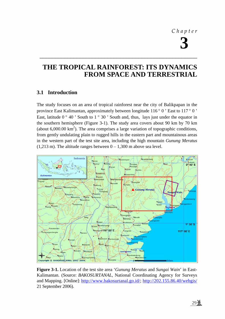
C h a p t e r
3 ___________________________________________________
3 THE TROPICAL RAINFOREST: ITS DYNAMICS FROM SPACE AND TERRESTRIAL
3.1 Introduction The study focuses on an area of tropical rainforest near the city of Balikpapan in the province East Kalimantan, approximately between longitude 116 ° 0 ’ East to 117 ° 0 ’ East, latitude 0 ° 40 ’ South to 1 ° 30 ’ South and, thus, lays just under the equator in the southern hemisphere (Figure 3-1). The study area covers about 90 km by 70 km (about 6,000.00 km2). The area comprises a large variation of topographic conditions, from gently undulating plain to rugged hills in the eastern part and mountainous areas in the western part of the test site area, including the high mountain Gunung Meratus (1,213 m). The altitude ranges between 0 – 1,300 m above sea level.
Figure 3-1. Location of the test site area ‘Gunung Meratus and Sungai Wain’ in East-Kalimantan. (Source: BAKOSURTANAL, National Coordinating Agency for Surveys and Mapping. [Online]: http://www.bakosurtanal.go.id/; http://202.155.86.40/webgis/ 21 September 2006).
Gunung MeratusSungai Wain
29

Spaceborne radar monitoring of forest fires and forest cover change
30
This area experienced long drought periods associated with the El Niño Southern Oscillation (ENSO)1 phenomenon and its extremes. An El Niño period is often followed by a wetter period in a biannual cycle. In terms of rainfall this means that year-to-year changes in rainfall can be extremely high (Brookfield and Byron, 1993). During the 1997 – 1998 El Niño event this area suffered from (wild)-fires due to both natural and human causes. The fires spread to very wide areas and were responsible for not only the loss of human lives and displacement of hundreds of thousands from their homes but also for forests loss and degradation and the regional – national economic catastrophe (Makarim et al., 1998). The test site area is characterised by a complex mosaic of vegetation and land cover types. Almost 75 % of the test site area is covered by forest. Typical tropical lowland evergreen and semi-evergreen rainforests dominate the natural vegetation with Dipterocarpaceae (Shorea spp, Dipterocarpus spp, Dryobalanops spp. etc) as the dominant family (Soerianegara & Lemmens, 1993; Whitmore, 1984, 1998). Large parts of the natural forest have been logged and are nowadays covered by secondary vegetation i.e. forests. Partly, the logged-over areas are converted to plantations of exotic tree species, of agricultural plantation (rubber, palm oil) and of forest plantation (Bremen et al., 1990).
3.2 Climate According to the Köppen system (1931) in Beck et al (2006) this area is classified as a tropical rainy isothermal climate with hot summers (hottest month more than 22 °C), no dry season (mean precipitation in the driest month more than 60 mm) and two rainfall maxima (April – May and December – January). The mean annual rainfall in this area ranges between approximately 2,000 mm to 2,500 mm. Usually the months of June through October have less monthly rainfall than the remaining months of the year. The mean monthly rainfall in these months is more than 100 mm. The average air humidity is about 85 %, tops of 96 % occur in the wettest months (Bremen et al., 1990; Van den Berg, 1998).
1 “El Niño Southern Oscillation (ENSO) refers to the irregular warming of in the sea surface
temperatures from the coasts of Peru and Ecuador to the equatorial central Pacific. This causes a disruption of the ocean-atmosphere system in the tropical Pacific having important consequences for the weather around the globe. This phenomenon is not totally predictable but on average occurs once every four years. It usually lasts for about 18 months after it begins.
During the 1997-1998 El Niño, sea surface temperatures in the central and eastern equatorial Pacific were higher than normal. The sea surface temperature for September 1997 was the highest in the last 50 years. Also, in late September easterly winds over the equatorial Pacific between 150E and 120W showed the strongest decrease in the last 30 years, making it the strongest El Niño of the past century. It caused droughts and fires in Australia, Southern Africa, Central America, Indonesia, the Philippines, South America and India.” http://www.oar.noaa.gov/k12/html/elnino2.html [Online]. Accessed on 5 October 2006

3. The tropical rainforest: its dynamics from space and terrestrial.
31
The mean monthly temperature of this area is recorded as 27 °C. A highest daytime temperature is 35 °C and a lowest nighttime temperature is 19 °C (Bremen et al., 1990, See Table 3-1). The Wanariset-Samboja2 weather monitoring station data, which were taken in 1996 and 1998 (during El Niño), are shown in the following table.
Table 3-1. Climatic data in the Wanariset area
Month/Year
Average Humidity
%
Average Temperature
°C
Rainfall mm
Rainday days
1996 1998 1996 1998 1996 1998 1996 1998 1. January 93.0 94.4 26.5 27.4 316.4 32.4 17 4 2. February 87.4 65.5 28.3 31.3 223.3 0.0 17 0 3. March 87.2 59.0 28.2 32.7 159.3 0.0 15 0 4. April 87.1 68.9 26.5 32.4 188.8 116.7 16 7 5. May 87.1 75.5 26.9 30.5 118.2 176.5 6 12 6. June 87.9 74.4 27.0 27.1 216.1 331.9 13 21 7. July 88.9 80.2 26.3 28.0 175.4 274.9 7 22 8. August 85.6 78.4 26.5 28.2 332.1 133.2 19 18 9. September 87.4 76.6 27.3 29.2 150.8 86.6 10 13 10. October 92.2 78.1 26.6 29.0 109.4 220.4 16 12 11. November 89.6 78.4 26.1 28.6 90.0 234.7 19 18 12. December 82.2 77.9 26.9 28.5 178.8 270.8 18 21
Total - - - - 2,258.6 1,878.1 - - Graphically these data are presented in Figure 3-2.
0
50
100
150
200
250
300
350
Jan Feb Mar Apr May Jun Jul Aug Sep Oct Nov Dec
Rai
nfal
l (m
m)
.
0
4
8
12
16
20
24
28
32
36
(oC)
Rainfall 96 Rainfall 98 Temp 96 Temp 98Trend R96 Trend R98
Figure 3-2. Weather data of 1996 and 1998 in the period of El Niño at the Wanariset-Samboja station
2 Wanariset-Samboja is the Ministry of Forestry (MOF)-Tropenbos Kalimantan Research Station,
being located inside the test site area.

Spaceborne radar monitoring of forest fires and forest cover change
32
Another weather station is the Tropical Rain Forest Research Centre of Mulawarman University near the test site, showing the air temperature and humidity of this area in Table 3-2.
Table 3-2. Temperature and relative humidity of the air at the Tropical Rain Forest Research Centre of Mulawarman University on 1988 – 1998 (Source: Guhardja et al., 2000.)
3.3 Geology and topography The geology of East Kalimantan is dominated by folded Miocene sedimentary rock that consists mainly of Tertiary sedimentary rocks, which were formed when the island was still under sea. After withdrawal of the sea, erosion processes started, resulting in the present relief and landform. Distributions of the landform pattern were distinguished based on physiographic features. The test site area is characterised by a mountain string (northeast to southwest) with rather steep hills to steep hills, coastal beach ridges, hillocky plains and undulating plains (Bremen et al., 1990). The topography of the area according to the topographic map (scale of 1:50,000) is relatively undulating; the average slope is 8 – 30 %, and the elevation is between 50 and 150 m above sea level.
3.4 Soils In East Kalimantan, clayey or sandy soils have developed on the Tertiary mother material. The most extensive soils are red and yellow podsolic soils, also called Ultisols. The nutrient status of these soils is low, in particular where the topsoil is thin or absent. This is mainly because of the low mineral reserves of the parent material from which these soils have developed. These are strongly weathered and leached soils with a clay intrusion layer and low-base saturation (Bremen et al., 1990). The base saturation decreases with increasing soil depth, which means that bases are directly cycled in the vegetation (Van den Berg, 1998). The next common groups of soils are Reddish Brown Lateritics, Yellowish Brown Lateritic and Latosol. These are presently called Oxisols. Their structures is very stable and consist of fine and stable aggregates, hence the water availability is very low. Characteristic is the oxide upper layer of at least 30 cm. The subsurface is very weathered and consists of insoluble minerals like quartz and iron (Van den Berg, 1998).
Month Years 1988 – 1998 Jan Feb Mar Apr May Jun Jul Aug Sep Oct Nov Dec
Mean
Temperature (°C ) Maximum 29.5 29.3 30.3 30.6 29.9 29.6 29.1 30.0 30.7 30.6 29.9 28.8 29.9 Minimum 21.7 21.3 21.9 21.8 21.4 21.1 21.0 21.0 20.7 21.7 21.3 21.5 21.4
Relative Humidity (%) Maximum 95.4 94.9 94.7 93.0 93.5 93.3 92.1 93.2 92.5 91.0 91.6 92.8 93.2 Minimum 63.0 59.7 57.7 55.1 62.7 62.0 61.5 56.2 53.7 53.7 57.7 59.0 58.5

3. The tropical rainforest: its dynamics from space and terrestrial.
33
3.5 Land systems Land systems, or landforms, result from weathering and erosion processes acting on different kinds of rock. Consequently they depend on three main factors: climatic conditions, the nature and structural arrangements of the substratum, and the time given for morphogenic process (Desaunettes, 1977). Based on the Land System map 1:250,000 Regional Physical Planning Programme for Transmigration (RePPProT, 1987) the test site area consists of 13 land systems from coastal to hilly systems (See Figure 3-3). The coastal beach (PTG) in the southern part consists of shifting arrangements of sediments along shore. These seaward-sloping deposits are shaped by wave and current action between tidal and storm limits. Inter-tidal mudflat (KJP) is a marshy or muddy land area along the river branch which is covered and uncovered by the rise and fall of the tide. A mud-flat in this area is really in indirect contact with the sea and supports mangrove trees. Coalescent estuarine (KHY) or riverine plain is a landform of the alluvia-marine which has a deposit of sediments formed at the mouth of a river or in the ocean. Swampy floodplain (BLI) is low spongy land, generally saturated with moisture in narrow valleys. The other category of land systems consist of hilly systems being composed of hills and hillocks. These landforms have been made by orogenic and erosion processes, by the folding of sedimentary layers, or by the dissection of older surfaces. The test site area is dominated by asymmetric sedimentary hills (MPT) and hillocky sedimentary plains (TWH). According to Dolphin Books (1962) in Ramdhani (2003) in general, the term ‘hill’ is a restricted to more or less abrupt elevation of no more than 330 m, all altitudes exceeding this being mountains. In this test site area the elevation of hills is less than 150 m. Hills and hillocks have slopes which are generally scalloped and consist of drainage lines, longitudinal valley, and special features such as undulating to rolling sedimentary plains (LWW) at the foot of a sedimentary hills (MPT) or hillocky sedimentary plains (TWH), Hillocky sedimentary with steep ridges (TWB), sedimentary ridges (LHI), sedimentary ridge systems with steep dip slopes (MTL), and minor valley floors within hills (BKN).

Spaceborne radar monitoring of forest fires and forest cover change
34
Figure 3-3. Land system in the Gunung Meratus test site area, being indicated by
the red box
Land system codes are listed in Tables 3-3 and 3-4. There are three dominant land systems in this test area: Hillocky sedimentary (TWH) 24.5 %, Sedimentary mountains (PDH) 23.4 % and Sedimentary hills (MPT) 21.8 %
Table 3-3. Land system area distribution of the Gunung Meratus test site area
No LS-No Code Land system Area (ha) % 1 1118 BKN Minor valley floors 907 0.2 2 1119 BLI Swampy floodplains 2,950 0.8 3 1153 KHY Coalescent estuarine 2,451 0.6 4 1154 KJP Inter-tidal mudflats 11,832 3.1 5 1167 LWW Undulating to rolling 33,726 8.8 6 1174 MPT Sedimentary hills 83,333 21.8 7 1176 MTL Linear, sedimentary ridge systems 21,091 5.5 8 1180 PDH Sedimentary mountains 89,517 23.4 9 1191 PTG Coastal beach 195 0.1
10 1220 TWH Hillocky sedimentary 93,445 24.5 11 1251 BRW Mountainous sandstone 10,342 2.7 12 1260 TWB Hillocky sedimentary 8,023 2.1 13 1261 LHI Sedimentary ridges 1,868 0.5 14 1247 NO DATA NO DATA 22,497 5.9
Total area 382,178 100.0 Calculations of the areas are based on the Land system map 1:250,000 (RePPProT, 1987). Water bodies were not included in the calculation.

3. The tropical rainforest: its dynamics from space and terrestrial.
35
Table 3-4. Complete description of the land system in the Gunung Meratus test site area (Source: Land system map 1:250,000 RePPProT, 1987).
No LS-No Code Description 1 1118 BKN Minor valley floors within hills2 1119 BLI Swampy floodplains of narrow valleys 3 1153 KHY Coalescent estuarine/riverine plains 4 1154 KJP Inter-tidal mudflats under mangrove and nipah 5 1167 LWW Undulating to rolling sedimentary plains 6 1174 MPT Asymmetric, non-orientated sedimentary hills 7 1176 MTL Linear, sedimentary ridge systems with steep dip slopes 8 1180 PDH Non-orientated, sedimentary mountains 9 1191 PTG Coastal beach ridges and swales
10 1220 TWH Hillocky sedimentary plains 11 1251 BRW Mountainous sandstone cuestas with dissected dip slopes 12 1260 TWB Hillocky sedimentary plains with steep parallel ridges 13 1261 LHI Long, narrow-crested, steep-sided sedimentary ridges 14 1247 NO DATA NO DATA
3.6 Rivers Based on the 1:250,000 scale topographic maps of BAKOSURTANAL, the National Coordinating Agency for Surveys and Mapping (1991), which is a generalization from the topographic map at the 1:50,000 scales, the Gunung Meratus test site area contains several big rivers (See Figure 3-4). In the eastern part the Semoi River, the Bugis River, and the Wain River, the latter flowing to the Balikpapan Bay from north to south. In the middle of the test site large rivers flow from west to east, viz. the Pemaluan River, the Kernun River, and the Riko River, which also have estuaries in the Balikpapan Bay. In the middle of the test site area big rivers flow to the Makassar Strait, viz. the Luman River, the Toyu River, and the Telake River. In the western part of the test site rivers are flowing in the northern direction, viz, the Bongan River and the Gusuk River, which both stream to the wide Mahakam River. Besides the rivers mentioned, many small streams and (branch)-rivers flow through the area. Also waterfalls are found in several rivers and streams. Near the rivers, and in some other places, ponds of stagnant water can be found. In several places in this test site area the big rivers are used as a transportation network.

Spaceborne radar monitoring of forest fires and forest cover change
36
Figure 3-4. Rivers and Road network of the test site area. Rivers are in blue line, road network in magenta, the red box indicates Gunung Meratus test site area and the purple box indicates Sungai Wain test site area. (Note: Sungai (or S.) = River; S. Wain = Wain River).
3.7 Road network The main road in this area is the trans-Kalimantan asphalt road which connects the provinces East Kalimantan and South Kalimantan. It has two lanes, is 6 to 10 m wide, accesses the south-eastern part of this test site area, and branches into the entire test area. Figure 3-4 shows also the road network in the test site area. In the transmigration area, where the settlements are, the road network is quite dense. In the eastern part is asphalt (paved), but the western part is unpaved. Besides those roads, in the forest area there are forests roads (rock-paved road), which are operated and maintained by forest logging companies for their activities. In the plantation area there are rock-paved roads as well, which have been built previously for logging company activities. In several places these roads are not well maintained. There are also paths and tracks that are constructed for plantation operations. Most of the roads can be easily reached by four-wheel drive vehicles, but in some places, especially during the rainy season, the area is difficult to access.
S. Riko
S. Semoi
S. Luman Bay
S. Bongan
S. Wain
S. Bugis
S. Pemaluan
S. Gusuk
S. Telake
S. Toyu
S. Kernun
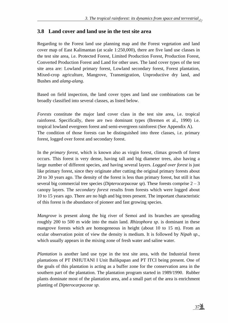
3. The tropical rainforest: its dynamics from space and terrestrial.
37
3.8 Land cover and land use in the test site area Regarding to the Forest land use planning map and the Forest vegetation and land cover map of East Kalimantan (at scale 1:250,000), there are five land use classes in the test site area, i.e. Protected Forest, Limited Production Forest, Production Forest, Converted Production Forest and Land for other uses. The land cover types of the test site area are: Lowland primary forest, Lowland secondary forest, Forest plantation, Mixed-crop agriculture, Mangrove, Transmigration, Unproductive dry land, and Bushes and alang-alang. Based on field inspection, the land cover types and land use combinations can be broadly classified into several classes, as listed below. Forests constitute the major land cover class in the test site area, i.e. tropical rainforest. Specifically, there are two dominant types (Bremen et al., 1990) i.e. tropical lowland evergreen forest and semi-evergreen rainforest (See Appendix A). The condition of those forests can be distinguished into three classes, i.e. primary forest, logged over forest and secondary forest. In the primary forest, which is known also as virgin forest, climax growth of forest occurs. This forest is very dense, having tall and big diameter trees, also having a large number of different species, and having several layers. Logged over forest is just like primary forest, since they originate after cutting the original primary forests about 20 to 30 years ago. The density of the forest is less than primary forest, but still it has several big commercial tree species (Dipterocarpaceae sp). These forests comprise 2 – 3 canopy layers. The secondary forest results from forests which were logged about 10 to 15 years ago. There are no high and big trees present. The important characteristic of this forest is the abundance of pioneer and fast growing species. Mangrove is present along the big river of Semoi and its branches are spreading roughly 200 to 500 m wide into the main land. Rhizophora sp. is dominant in these mangrove forests which are homogeneous in height (about 10 to 15 m). From an ocular observation point of view the density is medium. It is followed by Nipah sp., which usually appears in the mixing zone of fresh water and saline water. Plantation is another land use type in the test site area, with the Industrial forest plantations of PT INHUTANI I Unit Balikpapan and PT ITCI being present. One of the goals of this plantation is acting as a buffer zone for the conservation area in the southern part of the plantation. The plantation program started in 1989/1990. Rubber plants dominate most of the plantation area, and a small part of the area is enrichment planting of Dipterocarpaceae sp.
Spaceborne radar monitoring of forest fires and forest cover change
38
Some common plantation treatments like weeding, and cleaning the ground floor was done. Usually the rubber trees are planted in rows, columns and in compartments. Each of the compartments is determined by the year of plantation. Transmigration. There are two large transmigration areas in this location, namely Semoi-Sepaku and Bongan Transmigration areas, comprising settlement areas, which contain social, economical, and health facilities and an intensive road network. Agricultural farmland is approximately 2 – 4 ha in size for each family to cultivate dry land crops, paddy rice (wet or dry rice fields) and cash crops such as pepper. Land clearing and land preparation in the transmigration area has been done by clear cutting the converted production forest, being logged-over forest or secondary forest. So in these areas almost no high and big trees are left. Clear felled areas appear in many places in the Gunung Meratus and Sungai Wain test site area. After land clearing these are left for fallow or are covered by crops to create a ladang (or kebun, mixed farming garden). Bushes and/or alang-alang (Imperata cylindrica) grasses have covered many areas, being relatively dense and up to 1 m high or more. In some places, these areas seem to be man-made, but were not planted by any crop and left for fallow. Figure 3-5 shows the field photographs of the Sungai Wain test site area. The photographs were taken during field data acquisition about one year after the severe forest fires of 1997 – 1998 in East Kalimantan (See Figure 3-1 and 3-9).

3. The tropical rainforest: its dynamics from space and terrestrial.
39
Figure 3-5. Field photographs of the Sungai Wain test site area: : a. mangrove; b. nipah (palm mangrove); c. rice field (agricultural); d. dry land agricultural; e. forest unburnt; f. forest unburnt; g. forest burnt; h. forest burnt; i. rubber plantation burnt; j. kebun/ladang (mixed farming garden).
d
i j
c
ba
e
g h
f
Spaceborne radar monitoring of forest fires and forest cover change
40
3.9 Forest fires – its behaviour and impact on the test site area Forest fires occur almost every year in this test site area, however, each event is specific in intensity and extent. For more than two decades East Kalimantan has had a serious forest fire problem. In 1982/1983 the largest forest fire of the century burned for several months through Kalimantan (Boer, 2002). Brown and Davis (1973) explain that by definition a forest fire is any wild-fire that has not been planned. A more descriptive definition is: uncontained and freely spreading combustion, which consumes the natural fuels of a forest, that is duff, litter, grass, dead branch wood, snags, logs, stumps, weeds, brush, foliage, and to a limited degree, green trees.
3.9.1 Fire behaviour The essential characteristic of a forest fire is that it is unconfined and free to spread. A very useful synonym coming into increasing use is “free-burning”. A “free-burning fire” is a fire free to respond to its environment. Fire reacts due to chance combinations of natural fuels, weather and topography. A free-burning fire may long remain only a smouldering spot or it may quickly develop to become a very big fire. A useful and accepted classification of fires is based on the degree to which fuels from mineral soil upward to treetops were involved in combustion. This is in effect a fire behaviour classification. This classifies all fires as ground, surface, or crown fires (Brown and Davis, 1973). A ground fire consumes the organic material beneath the surface litter of the forest floor. A ground fire may and often does follow a surface fire, depending on the moisture content of the organic layer; and spreading within rather than on top of the organic mantle. It is characterised by a slowly smouldering edge with no flame and little smoke. Ground fires are often hard to detect and are the least spectacular and slowest moving, however, it is the most destructive of all fires, and the most difficult to control. Ground fire is very common in degraded peat swamp forests. A surface fire is a fire that burns surface litter, other loose debris of the forest floor and small vegetation. This is the most common type of fire in timber stands of all species. It may be a mild, low energy fire in grass and litter, or it may be a very hot, fast moving fire where slash, flammable understory shrubs, or other abundant fuel prevail. A surface fire may and often does burn up into the taller vegetation and tree crowns as it progresses. Surface fires are by far the most common, and nearly all fires start as such. A crown fire is a fire that advances from top to top of trees or shrubs more or less independently of the surface fire. In dense forest stands on steep slopes or on level ground, with a brisk wind, the crown fire may race ahead of the supporting surface fire. This is the most spectacular kind of forest fire. A fire moving through the crowns of shrubs is also a crown fire. A crown fire does not necessarily run ahead of the surface fire.

3. The tropical rainforest: its dynamics from space and terrestrial.
41
Fire combination. In actual fire situations, ground, surface and crown fires may occur simultaneously and in all kinds of combinations. A surface fire may spread into the crowns and develop into a sweeping crown fire. A crown fire may drop to the ground and become a surface fire. Similarly, a surface fire may develop into a ground fire that may plague control forces for days or weeks. On a hot, dry, and windy circumstance, a rather innocuous appearing ground fire may be fanned into a surface or crown fire. Figure 3-6 illustrates the basic nature of these three kinds of forest fires.
Figure 3-6. Kinds of forest fire. A. Ground fire. B. Surface fire. C. Crown fire (Brown and Davis, 1973)
Fire in the forest is caused by the combination of three elements: oxygen, heat and fuel. Oxygen is always available in the forest. The heat can be developed naturally through a prolonged dry season and/or by human activity, on purpose or by accident. The ignition, build-up, and behaviour of fire depend on fuels more than on any other single factor. It is the fuel that burns that generates the energy and that largely determines the rate and level of intensity of that energy. Other factors that are important to fire behaviour must always be considered in relation to fuels. In short: no fuels, no fire.
A
B
C
Mineral Soil
Organic layer
Burning edge
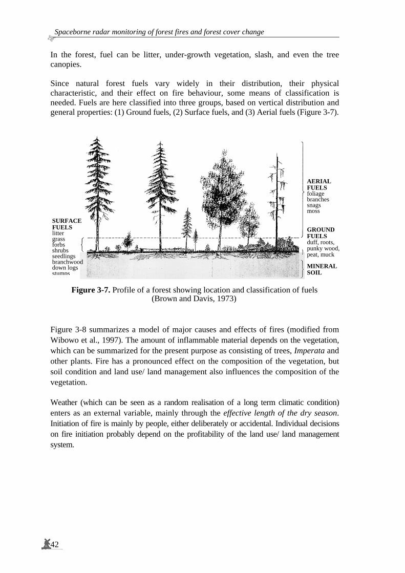
Spaceborne radar monitoring of forest fires and forest cover change
42
In the forest, fuel can be litter, under-growth vegetation, slash, and even the tree canopies. Since natural forest fuels vary widely in their distribution, their physical characteristic, and their effect on fire behaviour, some means of classification is needed. Fuels are here classified into three groups, based on vertical distribution and general properties: (1) Ground fuels, (2) Surface fuels, and (3) Aerial fuels (Figure 3-7).
Figure 3-7. Profile of a forest showing location and classification of fuels (Brown and Davis, 1973)
Figure 3-8 summarizes a model of major causes and effects of fires (modified from Wibowo et al., 1997). The amount of inflammable material depends on the vegetation, which can be summarized for the present purpose as consisting of trees, Imperata and other plants. Fire has a pronounced effect on the composition of the vegetation, but soil condition and land use/ land management also influences the composition of the vegetation. Weather (which can be seen as a random realisation of a long term climatic condition) enters as an external variable, mainly through the effective length of the dry season. Initiation of fire is mainly by people, either deliberately or accidental. Individual decisions on fire initiation probably depend on the profitability of the land use/ land management system.
SURFACE FUELS litter grass forbs shrubs seedlings branchwood down logs stumps
AERIAL FUELS foliage branches snags moss
GROUND FUELS duff, roots, punky wood,peat, muck
MINERALSOIL

3. The tropical rainforest: its dynamics from space and terrestrial.
43
Figure 3-8. Model of the causes (fuel, weather and human/people) of fire.
3.9.2 Potential factors causing forest fire in Indonesia Flame is, of course, not the only factor responsible in causing great wildfire in the tropical rainforest. In Indonesia this is especially true for East Kalimantan. There are many direct and indirect factors interacting together promoting the spread of fire. Below are the factors that are potential in promoting and/or causing the majority of wildfires particularly in the tropical rainforest (Hadrianto et al., 1997): Natural fuel. Coal is a natural fuel, which is often present between soil profiles. The fire progresses through the underground of the forest when the opened coal seams on the forest ground are consumed by fire. The burning of underground coal seams may continue for months or even years, and is hard to extinguish even by daily heavy rain. Drilling of natural oil is often conducted in the forest, and the oil is pumped through pipes to the factory. Usually, there is much oil spilled widely on the forest ground around the oil well. The spilled oil is certainly a fire hazard. Accumulation of dead biomass. The undecomposed litter accumulates on the forest ground and in many parts of wet lowland it decays gradually into raw humus or peat, which can reach up to 20 m in depth. Under normal conditions, meaning that the rain falls regularly, such row humus and peat are extremely wet or watery. However, under prolonged drought season, such as that caused by El-Niño, the peat and the accumulated of undecomposed-litter will dry up progressively, and change into potential fuel which is ready to burn anytime.
VEGETATION
LAND USE/ LAND MANAGEMENT
FIRE Intensity Spread
Random
WEATHER
SOIL Condition Moisture Fertility Slope
CLIMATE
FUEL HUMAN

Spaceborne radar monitoring of forest fires and forest cover change
44
Flammable plant. Natural resin is a fuel and is highly flammable. Notably Shorea javanica produces a lot of resin which is commercially known as damar. When such a tree is hit by lightning, this will start a prolonged fire. The continuous spill of resin on the forest floor increases the risk of fire. All the Dipterocarp trees, which dominate most parts of the forest, produce resin, and hence these forest parts are flammable. At most ridges and/or slopes, these tree species mostly grow in clumps to form stands that often occupy relatively large areas. Logging companies. By leaving behind deformed logs and branches as waste on forest ground, logging companies have increased the accumulation of potential fuel on the forest ground. In addition, logging activities cause opening of forest which in turn stimulates blast growth near the ground increasing the accumulation of biomass near the forest ground. An extremely long drought season dries this plant biomass into potential fuel. Therefore, logging activities can increase greatly both the forest fire risk and hazard. The indirect role of logging activities to increase fire risk is that the access of road networks opens up the forest to both immigrant and local people for making fields. Forest conversion programs. When part of the forest is converted into other land use, such as commercial agricultural, transmigration, mining, industrial forest (tree) plantation, and the like, fire is almost the only tool being used for land clearing. Such use of fire, as long as well-controlled, can be the most efficient and effective way, as it is able to clean a wide forest area within relatively short time. However, the irresponsible use of fire constitutes a potential agent for large forest burning. Therefore, the conversion of natural forest has also been considered being responsible for the escalating pressure of the wildfire of the tropical rainforest (Oka, 1997). Swidden agriculture/ shifting cultivation. Clearing and burning fields initiate Swidden agriculture, which has been practised traditionally by rural people. With the intention of planting crops at the beginning of the rainy season in November or December, the farmers usually clear and then burn their fields during the second half of the less rainy period (season), in September or October (Wirawan, 1993 in Oka, 1997). During the normal climate variation, this means that the rain is still falling occasionally: fire from slashed-and-burned field hardly spreads over the wet litter under the closed forest canopy. However, under a prolonged drought season attributed to the El-Niño event, the fire can easily spread beyond the fields to consume the dried dead-biomass and burn the forest down.
3.10 ERS and ENVISAT SAR time series acquisition
ERS The European Remote Sensing (ERS) satellite from the European Space Agency (ESA) carries several instruments for the observation of land and sea surfaces.

3. The tropical rainforest: its dynamics from space and terrestrial.
45
The images of the earth are collected with the ‘Active Microwave Instrument’ (AMI), which contains a Synthetic Aperture Radar (SAR). The aim of this satellite and its successors (ERS-2 and ENVISAT) is the worldwide monitoring of oceans, coastal waters, polar seas and ice, but is also rather suitable for land surface monitoring. ESA launched its first remote sensing satellite, ERS-1, on 17 July 1991. ERS-1 had a projected life span of 8 years but the mission was ended on 10 March 2000 and its successor, the ERS-2 launched on 21 April 1995, was designed to provide data for a further 5 year’s period. It is however still operational. The ERS-2 mission benefited greatly from the expertise and experience gained with ERS-1 in terms of data processing and dissemination, sensor calibration and data validation (Francis et al., 1995). ERS-2 was operated in 1995 – 1996 in tandem with ERS-1 to provide SAR image pairs having relatively short (one day) revisit times in support of SAR interferometry (Henderson and Lewis, 1998). ERS-1 (E1) and ERS-2 (E2) use the C-band Active Microwave Instrument (AMI) module. The AMI produces SAR data over a 100 km swath at a nominal resolution in range of 33 m and a nominal resolution in azimuth of 30 m with VV polarisation. The incidence angle at the first range pixel is about 19.5°, at the centre range pixel 23.0° and at the last range pixel 26.5°. Line and pixel spacing are 12.5 m (See also Table 3-5).
ENVISAT The Envisat (Environmental Satellite) is an Earth-observing satellite built by the European Space Agency. It was launched on March 1, 2002 aboard an Ariane 5 rocket launcher into a Sun synchronous polar orbit at a height of 790 km (±10 km). It orbits the Earth in about 101 minutes with a repeat-cycle of 35 days. Envisat carries 10 sophisticated optical and radar instruments to provide continuous observation and monitoring of the Earth's land, atmosphere, oceans and ice caps. Envisat data collectively provide a wealth of information on the processes of the Earth system, including insights into factors contributing to climate change. Its single largest instrument, the Advanced Synthetic Aperture Radar (ASAR) operating at C-band, ensures continuity of data after ERS-2. It features enhanced capability in terms of coverage, range of incidence angles, polarisation, and modes of operation. The improvements allow radar beam elevation steerage and the selection of different swaths, 100 or 400 km wide. Table 3-5 summarizes the ERS-SAR and ENVISAT ASAR characteristics. The Medium Resolution Imaging Spectrometer (MERIS) is an imaging spectrometer that measures the solar radiation reflected by the Earth, at a ground spatial resolution of 300 m, with 15 spectral bands in the visible and near infra-red and is programmable with respect to width and position. MERIS allows global coverage of the Earth every 3 days (ESA, 2006).
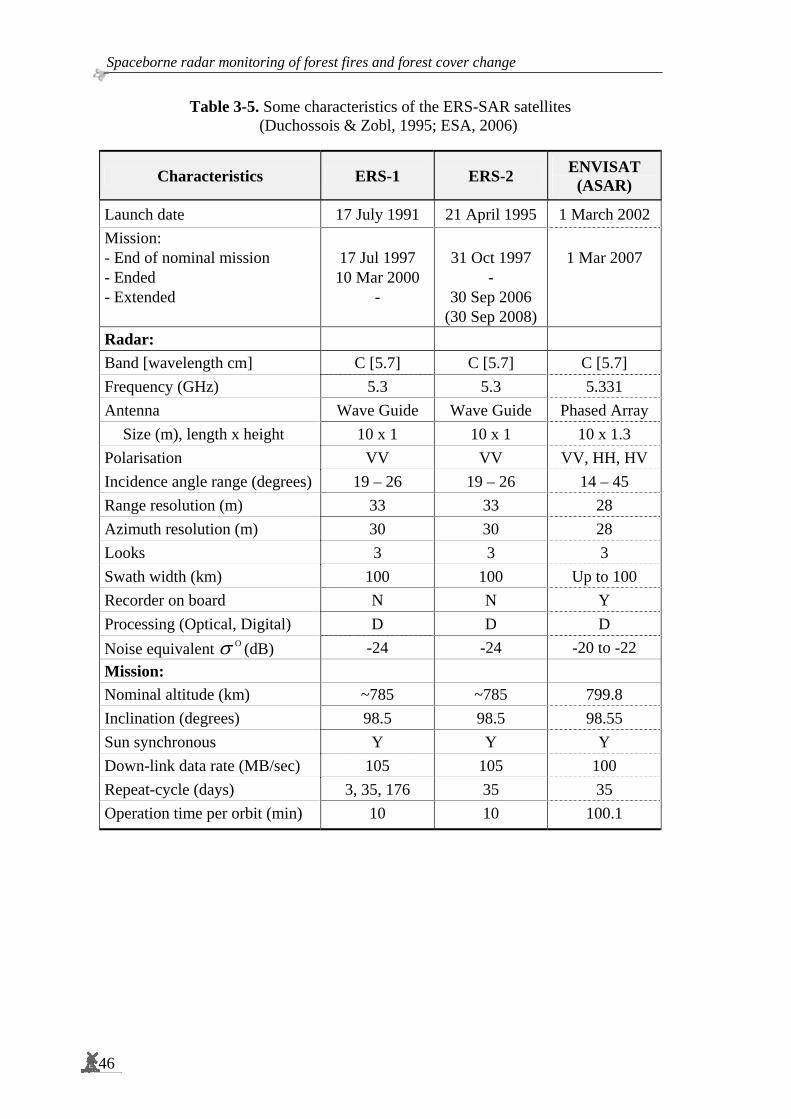
Spaceborne radar monitoring of forest fires and forest cover change
46
Table 3-5. Some characteristics of the ERS-SAR satellites (Duchossois & Zobl, 1995; ESA, 2006)
Characteristics ERS-1 ERS-2 ENVISAT (ASAR)
Launch date 17 July 1991 21 April 1995 1 March 2002 Mission: - End of nominal mission - Ended - Extended
17 Jul 1997 10 Mar 2000
-
31 Oct 1997
- 30 Sep 2006
(30 Sep 2008)
1 Mar 2007
Radar: Band [wavelength cm] C [5.7] C [5.7] C [5.7] Frequency (GHz) 5.3 5.3 5.331 Antenna Wave Guide Wave Guide Phased Array
Size (m), length x height 10 x 1 10 x 1 10 x 1.3 Polarisation VV VV VV, HH, HV Incidence angle range (degrees) 19 – 26 19 – 26 14 – 45 Range resolution (m) 33 33 28 Azimuth resolution (m) 30 30 28 Looks 3 3 3 Swath width (km) 100 100 Up to 100 Recorder on board N N Y Processing (Optical, Digital) D D D Noise equivalent Oσ (dB) -24 -24 -20 to -22 Mission: Nominal altitude (km) ~785 ~785 799.8 Inclination (degrees) 98.5 98.5 98.55 Sun synchronous Y Y Y Down-link data rate (MB/sec) 105 105 100 Repeat-cycle (days) 3, 35, 176 35 35 Operation time per orbit (min) 10 10 100.1

3. The tropical rainforest: its dynamics from space and terrestrial.
47
Characteristics of the ERS-1 and ERS-2 SAR Precision Images time series The major materials of this study are 22 data sets of ERS-1 and ERS-2 SAR Precision Images (PRI), which have been calibrated (See Table 3-6). Table 3-6. ERS-1 and ERS-2 SAR PRI data set and distribution of images in Julian Date. Image number 4 is of poor quality (calibration problem). Full scene data sets have 8000 pixels per line. The number of lines varies from 8255 to 8281 (in general there are at least 8200 lines). The table also shows the image serial number (No) and the interval in days between consecutive images.
No ERS Orbit Frame Acquisition Date Julian Date3 Interval
(days) 1 E1 11857 3627 19931022 2449283 - 2 E1 12358 3627 19931126 2449318 35 3 E1 21720 3627 19950910 2449971 653 4 E1 24726 3627 19960407 2450281 210 5 E2 5554 3627 19960513 2450217 36 6 E2 6556 3627 19960722 2450287 70 7 E2 7558 3627 19960930 2450357 70 8 E2 8059 3627 19961104 2450392 35 9 E2 9562 3627 19970217 2450497 105 10 E2 11065 3627 19970602 2450602 105 11 E2 15574 3627 19980413 2450917 315 12 E2 16075 3627 19980518 2450952 35 13 E2 16576 3627 19980622 2450987 35 14 E2 18079 3627 19981005 2451092 105 15 E1 38253 3627 19981108 2451126 34 16 E2 18580 3627 19981109 2451127 1 17 E1 38754 3627 19981213 2451161 34 18 E1 39756 3627 19990221 2451231 70 19 E2 20083 3627 19990222 2451232 1 20 E1 44766 3627 20000206 2451581 349 21 E1 25093 3627 20000207 2451582 1 22 E2 33610 3627 20010924 2452177 595
3 The Julian day or Julian day number (JDN) is the (integer) number of days that have elapsed
since Monday, January 1, 4713 BC in the proleptic Julian calendar 1. That day is counted as Julian day zero. Thus the multiples of 7 are Mondays. Negative values can also be used.
The Julian Date (JD) is the number of days (with decimal fraction of the day) that have elapsed since 12 noon Greenwich Mean Time (UT or TT) of that day. Rounding to the nearest integer gives the Julian day number.
The Julian day number can be considered as a very simple calendar, where its calendar date is just an integer. This is useful for reference, computations, and conversions. The Julian day system was introduced by astronomers to provide one with a single system of dates that could be used when working with different calendars and to unify different historical chronologies.

Spaceborne radar monitoring of forest fires and forest cover change
48
Figure 3-9 illustrates the coverage of the 22 data sets of ERS-1 and ERS-2; they are not always in the same position depending on the satellite orbit (Williams, 1995). Geographically, variations of the scene positions are sometimes very wide (Figure 3-9: area a). For that reason ‘sub-scenes’ have been selected. The first sub-scene is 20 km x 18 km and is called the Sungai Wain test site area (Figure 3-9: area b). Secondly, an extended sub-scene of 90 km x 70 km has been defined which is called the Gunung Meratus test site area (Figure 3-9: area c).
Figure 3-9. Stacking of time series of ERS-1 and ERS-2 SAR PRI Images data sets. a: 22 scenes ERS SAR PRI Images data; b: The Sungai Wain test site area (20 x 18 km2); c: The Gunung Meratus test site area (90 x 70 km2); and d: AirSAR data, PacRim-II test site (See Section 3.11).
The available 22 data sets are not regularly distributed in time. The interval, expressed in days, between the consecutive images vary a lot. This is easily seen by converting the date of acquisition to the Julian Dates (Table 3-6 and Figure 3-10). For example the interval between image serial numbers 10 and 11 is 315 days, while between image serial numbers 12 and 13 it is 35 days, which is exactly one repeat-cycle. Another example: between the images with serial numbers 20 and 21 it is only 1 day. Those images form a pair of ERS-1 and ERS-2 tandem images.
a
bc d

3. The tropical rainforest: its dynamics from space and terrestrial.
49
Figure 3-10. Distribution of time series images in Julian date Monthly distribution of the available 22 data sets over the year regarding the wet and dry season can be seen in Table 3-7 and Figure 3-11. Because of El Niño there is an anomaly in year 1998. Accordingly there is a very high rainfall in the dry season June – October (as has been discussed in Section 3.2). Table 3-7. The weather station of the Tropical Rain Forest Research Centre (TRFRC) of Mulawarman University shows the rainfall condition during 1993 – 1998 (Source: Guhardja et al., 2000.)
Month Year Jan Feb Mar Apr May Jun Jul Aug Sep Oct Nov Dec
Total
1993 75 138 149 169 247 177 44 33 50 84 65 113 1345 1994 106 144 209 118 203 82 12 30 0 148 136 211 1398 1995 108 172 140 296 178 331 168 298 119 144 184 209 2346 1996 197 473 114 206 156 182 130 158 90 316 207 243 2471 1997 297 244 256 176 186 51 105 9 1 51 190 243 1808 1998 1 0 0 137 218 302 335 278 171 250 256 333 2281 Mean
’93-‘97 157 234 174 193 194 165 92 106 52 149 156 204 1874 Mean
’93-‘98 131 195 145 184 198 188 132 134 72 166 173 225 1942
By knowing ‘the month’ of the data acquisition it can already be inferred whether it is in the wet or dry season. This information is important since radar is very sensitive to water or soil moistures (Kasischke & Bourgeau-Chavez, 1997; Sugardiman, 2000; Oevelen, 2000; and Wang et al., 2004). This area has the driest month between June and October. The wet seasons are in April – May and December – January (Bremen et al., 1990; Van den Berg, 1998).
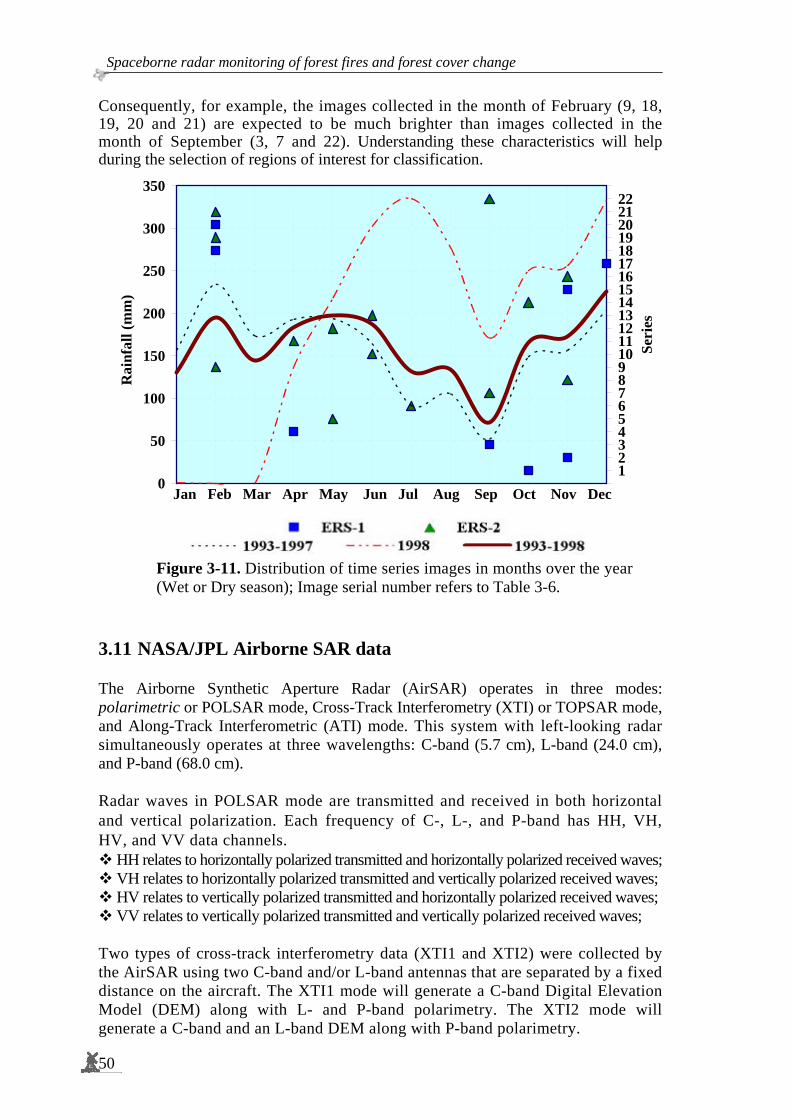
Spaceborne radar monitoring of forest fires and forest cover change
50
Consequently, for example, the images collected in the month of February (9, 18, 19, 20 and 21) are expected to be much brighter than images collected in the month of September (3, 7 and 22). Understanding these characteristics will help during the selection of regions of interest for classification.
0
50
100
150
200
250
300
350
1 2 3 4 5 6 7 8 9 10 11 12
Rai
nfal
l (m
m) .
.
01234567891011121314151617181920212223
Seri
es
Figure 3-11. Distribution of time series images in months over the year (Wet or Dry season); Image serial number refers to Table 3-6.
3.11 NASA/JPL Airborne SAR data The Airborne Synthetic Aperture Radar (AirSAR) operates in three modes: polarimetric or POLSAR mode, Cross-Track Interferometry (XTI) or TOPSAR mode, and Along-Track Interferometric (ATI) mode. This system with left-looking radar simultaneously operates at three wavelengths: C-band (5.7 cm), L-band (24.0 cm), and P-band (68.0 cm). Radar waves in POLSAR mode are transmitted and received in both horizontal and vertical polarization. Each frequency of C-, L-, and P-band has HH, VH, HV, and VV data channels.
HH relates to horizontally polarized transmitted and horizontally polarized received waves; VH relates to horizontally polarized transmitted and vertically polarized received waves; HV relates to vertically polarized transmitted and horizontally polarized received waves; VV relates to vertically polarized transmitted and vertically polarized received waves;
Two types of cross-track interferometry data (XTI1 and XTI2) were collected by the AirSAR using two C-band and/or L-band antennas that are separated by a fixed distance on the aircraft. The XTI1 mode will generate a C-band Digital Elevation Model (DEM) along with L- and P-band polarimetry. The XTI2 mode will generate a C-band and an L-band DEM along with P-band polarimetry.
Jan Feb Mar Apr May Jun Jul Aug Sep Oct Nov Dec
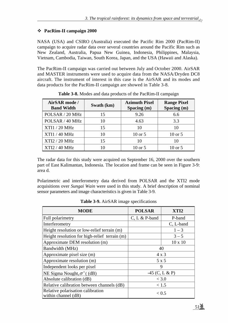
3. The tropical rainforest: its dynamics from space and terrestrial.
51
PacRim-II campaign 2000 NASA (USA) and CSIRO (Australia) executed the Pacific Rim 2000 (PacRim-II) campaign to acquire radar data over several countries around the Pacific Rim such as New Zealand, Australia, Papua New Guinea, Indonesia, Philippines, Malaysia, Vietnam, Cambodia, Taiwan, South Korea, Japan, and the USA (Hawaii and Alaska). The PacRim-II campaign was carried out between July and October 2000. AirSAR and MASTER instruments were used to acquire data from the NASA/Dryden DC8 aircraft. The instrument of interest in this case is the AirSAR and its modes and data products for the PacRim-II campaign are showed in Table 3-8.
Table 3-8. Modes and data products of the PacRim-II campaign
AirSAR mode / Band Width Swath (km) Azimuth Pixel
Spacing (m) Range Pixel Spacing (m)
POLSAR / 20 MHz 15 9.26 6.6 POLSAR / 40 MHz 10 4.63 3.3 XTI1 / 20 MHz 15 10 10 XTI1 / 40 MHz 10 10 or 5 10 or 5 XTI2 / 20 MHz 15 10 10 XTI2 / 40 MHz 10 10 or 5 10 or 5
The radar data for this study were acquired on September 16, 2000 over the southern part of East Kalimantan, Indonesia. The location and frame can be seen in Figure 3-9: area d. Polarimetric and interferometry data derived from POLSAR and the XTI2 mode acquisitions over Sungai Wain were used in this study. A brief description of nominal sensor parameters and image characteristics is given in Table 3-9.
Table 3-9. AirSAR image specifications
MODE POLSAR XTI2 Full polarimetry C, L & P-band P-band Interferometry C, L-band Height resolution or low-relief terrain (m) 1 – 3 Height resolution for high-relief terrain (m) 3 – 5 Approximate DEM resolution (m) 10 x 10 Bandwidth (MHz) 40 Approximate pixel size (m) 4 x 3 Approximate resolution (m) 5 x 5 Independent looks per pixel 9 NE Sigma Nought, oσ ( (dB) -45 (C, L & P) Absolute calibration (dB) < 3.0 Relative calibration between channels (dB) < 1.5 Relative polarisation calibration within channel (dB) < 0.5

Spaceborne radar monitoring of forest fires and forest cover change
52
3.12 Shuttle radar topography mission data The Shuttle Radar Topography Mission (SRTM4) was executed as a joint project between the National Geospatial-Intelligence Agency (NGA) and NASA (USA). The main mission objective was to use C-band and X-band interferometric synthetic aperture radars (InSARs or IFSARs) to acquire digital topographic data over 80 % of Earth's land mass (between 60o N and 56o S). Figure 3-12 shows a map of the world with the global coverage of the Shuttle Radar Topography Mission (SRTM) data (NASA/JPL, 2005).
Figure 3-12. Shuttle Radar Topography Mission (SRTM) Global Coverage Map. The colours of the swaths indicate the number of times the area was imaged by SRTM. For land, one-time coverage is green, twice is yellow-green and so on, as shown in the legend at the lower left. Over water, the colour code is in shades of blue as shown in the legend at the lower right. Areas in red could not be mapped (USGS, 2003: NASA/JPL, 2005).
4 The Shuttle Radar Topography Mission (SRTM) obtained elevation data on a near-global
scale to generate the most complete high-resolution digital topographic database of Earth. SRTM consisted of a specially modified radar system that flew onboard the Space Shuttle Endeavour (STS-99) during an 11-day mission in February 2000 [Launch: February 11, 2000, 12:44 pm EST, Landing: February 22, 2000, 06:22 pm EST at Kennedy Space Centre, Mission Duration: 11 days, 05 hours, 38 minutes]. To acquire topographic (elevation) data, the SRTM payload was equipped with two radar antennas. One antenna was located in the shuttle's payload bay, the other at the end of a 60 m mast that extended from the payload once the Shuttle was in space (USGS, 2003; NASA/JPL, 2005)

3. The tropical rainforest: its dynamics from space and terrestrial.
53
The Global Land Cover Facility (GLCF) editions of Shuttle Radar Topography Mission data are available in 6 layers (Table 3-10). The 1 and 3 arc-second editions were available in USGS format and were also tiled to the Landsat WRS-2 and re-projected to Universal Transverse Mercator (UTM) projection. The global 30 arc-second product was the result of mosaicing the USGS native tiles. For this study 3 arc-second (3”) or 90 m resolution was used (Table 3-11).
Table 3-10. Shuttle Radar Topography Mission (SRTM) Editions (Source: Global Land Cover Facility, 2004)
Resolution Projection Coverage
Geographic Native USGS Tiles 1 arc-second (1”)/ 30 m Universal Transverse Mercator WRS-2 Path/Row5
Geographic Native USGS Tiles 3 arc-second (3”)/ 90 m Universal Transverse Mercator WRS-2 Path/Row
Geographic Native USGS Tiles 1 km
Geographic Global
Kodde (2005) describes that the DEMs derived from SRTM measurements are stored in a raster format. This means that the continuous surface is discretised in a regular grid of cells or pixels. Each pixel has a value as attribute, which represents the height of the surface of the terrain. Table 3-11. Characteristic of the Shuttle Radar Topography Mission (SRTM) data.
*) Consistent with National Map Accuracy Standards (USGS, 1947, in: Kodde, 2005)
Characteristics SRTM 90 m data Pixel size Raster size Radar wavelength (cm) Height levels (m) Datum (horizontal) Datum (vertical) horizontal accuracy (absolute, m) vertical accuracy (absolute, m) vertical accuracy (absolute, m) Output file
3” x 3” Longitude and Latitude 1o x 1o (1,201 x 1,201 pixels) 5.6 (C-Band radar) 1 WGS84 geoid WGS84 geoid ± 20 [90 % circular error*)] ± 16 [90 % circular error*)] ± 20 [90 % circular error*)] 16-bit GeoTIFF
5 The Worldwide Reference System (WRS) is a global notation system for Landsat data. It
enables a user to inquire about satellite imagery over any portion of the world by specifying a nominal scene centre designated by PATH and ROW numbers.
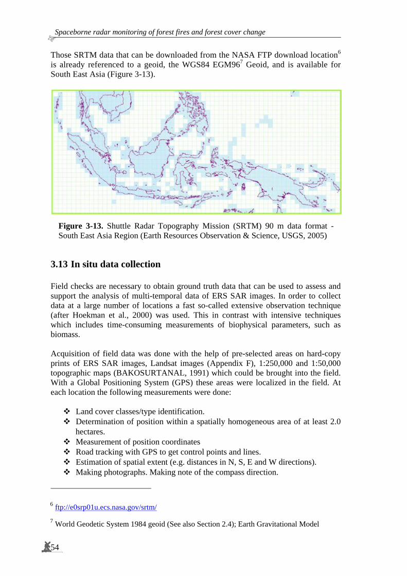
Spaceborne radar monitoring of forest fires and forest cover change
54
Those SRTM data that can be downloaded from the NASA FTP download location6 is already referenced to a geoid, the WGS84 EGM967 Geoid, and is available for South East Asia (Figure 3-13).
Figure 3-13. Shuttle Radar Topography Mission (SRTM) 90 m data format - South East Asia Region (Earth Resources Observation & Science, USGS, 2005)
3.13 In situ data collection Field checks are necessary to obtain ground truth data that can be used to assess and support the analysis of multi-temporal data of ERS SAR images. In order to collect data at a large number of locations a fast so-called extensive observation technique (after Hoekman et al., 2000) was used. This in contrast with intensive techniques which includes time-consuming measurements of biophysical parameters, such as biomass. Acquisition of field data was done with the help of pre-selected areas on hard-copy prints of ERS SAR images, Landsat images (Appendix F), 1:250,000 and 1:50,000 topographic maps (BAKOSURTANAL, 1991) which could be brought into the field. With a Global Positioning System (GPS) these areas were localized in the field. At each location the following measurements were done:
Land cover classes/type identification. Determination of position within a spatially homogeneous area of at least 2.0
hectares. Measurement of position coordinates Road tracking with GPS to get control points and lines. Estimation of spatial extent (e.g. distances in N, S, E and W directions). Making photographs. Making note of the compass direction.
6 ftp://e0srp01u.ecs.nasa.gov/srtm/ 7 World Geodetic System 1984 geoid (See also Section 2.4); Earth Gravitational Model
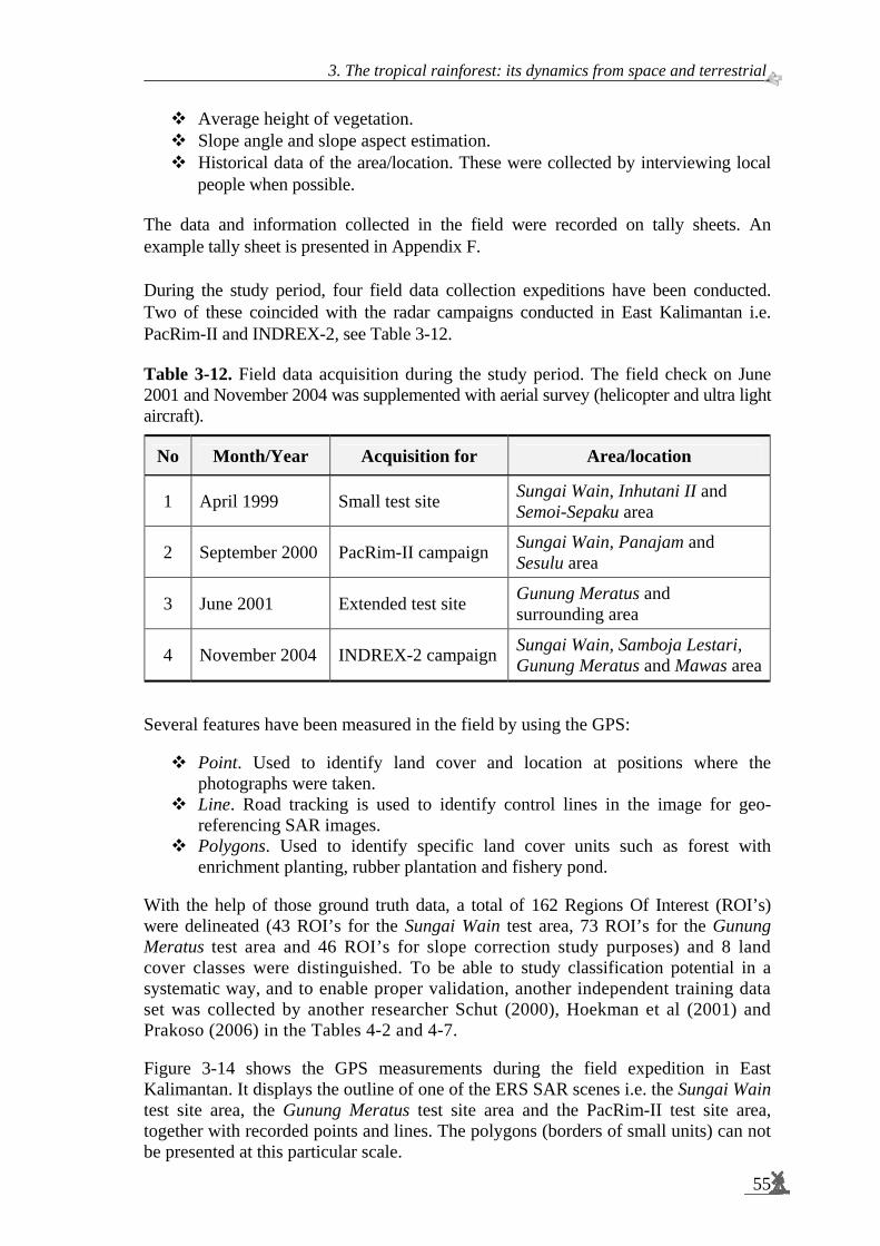
3. The tropical rainforest: its dynamics from space and terrestrial.
55
Average height of vegetation. Slope angle and slope aspect estimation. Historical data of the area/location. These were collected by interviewing local
people when possible. The data and information collected in the field were recorded on tally sheets. An example tally sheet is presented in Appendix F. During the study period, four field data collection expeditions have been conducted. Two of these coincided with the radar campaigns conducted in East Kalimantan i.e. PacRim-II and INDREX-2, see Table 3-12. Table 3-12. Field data acquisition during the study period. The field check on June 2001 and November 2004 was supplemented with aerial survey (helicopter and ultra light aircraft).
No Month/Year Acquisition for Area/location
1 April 1999 Small test site Sungai Wain, Inhutani II and Semoi-Sepaku area
2 September 2000 PacRim-II campaign Sungai Wain, Panajam and Sesulu area
3 June 2001 Extended test site Gunung Meratus and surrounding area
4 November 2004 INDREX-2 campaign Sungai Wain, Samboja Lestari, Gunung Meratus and Mawas area
Several features have been measured in the field by using the GPS:
Point. Used to identify land cover and location at positions where the photographs were taken.
Line. Road tracking is used to identify control lines in the image for geo-referencing SAR images.
Polygons. Used to identify specific land cover units such as forest with enrichment planting, rubber plantation and fishery pond.
With the help of those ground truth data, a total of 162 Regions Of Interest (ROI’s) were delineated (43 ROI’s for the Sungai Wain test area, 73 ROI’s for the Gunung Meratus test area and 46 ROI’s for slope correction study purposes) and 8 land cover classes were distinguished. To be able to study classification potential in a systematic way, and to enable proper validation, another independent training data set was collected by another researcher Schut (2000), Hoekman et al (2001) and Prakoso (2006) in the Tables 4-2 and 4-7. Figure 3-14 shows the GPS measurements during the field expedition in East Kalimantan. It displays the outline of one of the ERS SAR scenes i.e. the Sungai Wain test site area, the Gunung Meratus test site area and the PacRim-II test site area, together with recorded points and lines. The polygons (borders of small units) can not be presented at this particular scale.

Spaceborne radar monitoring of forest fires and forest cover change
56
Figure 3-14. Recordings of GPS in the Sungai Wain test site area, the Gunung Meratus test site area and the PacRim-II test site area respectively collected during the ground data collection activities.
Legend:
3. The tropical rainforest: its dynamics from space and terrestrial.
57
3.14 Summary and conclusions The study focuses on an area of tropical rainforest near the city of Balikpapan in the province East Kalimantan, and is about 90 km by 70 km in size. The area comprises a large variation of topographic conditions, from gently undulating plain to rugged hills in the eastern part and mountainous areas in the western part of the study area, including the high mountain Gunung Meratus (1,213 m). The study area contains 3 test site i.e. Sungai Wain test site area, the Gunung Meratus test site area and the PacRim-II test site area (See Figure 3-1 and Figure 3-9). The study area is characterised by a complex mosaic of vegetation and land cover types. Almost 75 % of the study area is or was covered by forest. Typical tropical lowland evergreen and semi-evergreen rainforests dominate the natural vegetation with Dipterocarpaceae as the dominant family. The mean annual rainfall in this area ranges between approximately 2,000 mm to 2,500 mm. There is no dry season (mean precipitation in the driest month more than 60 mm) and there are two rainfall maxima (April – May and December – January). This area experienced long drought periods associated with the El Niño Southern Oscillation (ENSO) phenomenon. For this study the severe ENSO event of 1997 – 1998 is of particular interest. For the test area the climate, geology, topography, soils, land systems, rivers and road network have been described in this thesis. Land cover classes comprise forests, including primary forests, secondary forests, mangroves, and industrial forest plantations. Most primary forests have been selectively logged. Large areas have been converted into alang-alang grass fields and bushy wastelands. Besides for forestry large areas are in use as agricultural land. It features mixed farming garden (kebun) and wet rice fields. Most agricultural activities are concentrated in transmigration areas. Forest fires occur almost every year in this test site area, however, each event is specific in intensity and extent. The essential characteristic of a forest fire is that it is unconfined and free to spread. A useful and accepted classification of fires is based on the degree to which fuels from mineral soil upward to treetops were involved in combustion. A ground fire consumes the organic material beneath the surface litter of the forest floor. Ground fires are often hard to detect and are the least spectacular and slowest moving, however, it is the most destructive of all fires, and the most difficult to control. Ground fire is very common in degraded peat swamp forests. A surface fire is a fire that burns surface litter, other loose debris of the forest floor and small vegetation. A crown fire is a fire that advances from top to top of trees or shrubs more or less independently of the surface fire.

Spaceborne radar monitoring of forest fires and forest cover change
58
Logging activities contribute to increased fire risk because it creates access through timber road networks and decreases forest crown closure causing increased exposure of ground litter to the sun. Under normal conditions fire from slashed-and-burned fields hardly spreads over the wet litter under a closed forest canopy. However, under a prolonged drought season attributed to the El-Niño event, the fire can easily spread beyond the fields to consume the dried dead-biomass, especially in selectively logged forests. Use has been made of 22 radar images, which were collected by the three consecutive ESA missions of ERS-1, ERS-2 and ENVISAT, spanning the period of 1993 to 2001. In addition use has been made of airborne radar data collected by the NASA AirSAR PacRim-II in 2000 and the Digital Elevation Model (DEM) derived from the NASA Space Shuttle Radar Topography Mission (SRTM), which was also executed in 2000. In-situ data has been collected during four periods at more than 200 locations. To get a better description of temporal changes local inhabitants were interviewed. These data sets were extended with two additional validation sets collected by other students of Wageningen University.

C h a p t e r
4 ___________________________________________________
4 LAND COVER CLASSIFICATION, FOREST FIRE AND CHANGE DETECTION
4.1 Introduction Chapter 4 focuses on the use, as well as on further refinements of the use, of the ERS-1 and ERS-2 SAR Precision Image (PRI) time series. A time series of 22 images have been processed to produce several types of maps at different points of time within this period. The basic processing tools being used are multi-temporal segmentation, physical model based pre-classification and Maximum Likelihood classification (Section 4.3). As an alternative for the computationally intensive multi-temporal segmentation the use of iterated conditional modes has been investigated (Section 4.4). The latter proves to be a viable alternative for fast and accurate map updating. In addition, tools utilizing slope correction (Section 4.5), textural features (4.6) and interferometric coherence (4.7) have been tested. Section 4.8 introduces the fire hotspot observations acquired by the NOAA-AVHRR instrument during the El Niño induced fire period in 1998. These hotspot data are useful for evaluation of the ERS radar mapping results. Section 4.9 describes the introduction and adaptation of the ERS SAR monitoring techniques developed in this thesis for operational application in a peat swamp forest area. Section 4.10 shows some important results of this operational application. The ERS-1 and ERS-2 SAR monitoring at the Sungai Wain test site area has been carried out within three phases of research. Initially, a large number of ERS-SAR scenes acquired in the 1993 – 1996 period of the East-Kalimantan Tropenbos test site were studied in support of the INDonesian Radar Experiment (INDREX-96) (Wooding et al., 1998). The objective was to study its potential for land cover change monitoring. Subsequently, an additional series of ERS-SAR scenes was acquired in support of studies to assess fire damage caused by the severe El Niño event, occurring at the same test site in the period June 1997 – April 1998. Finally, another series of ERS-SAR data was acquired to extend the period until the year 2001 and in a wider area, the Gunung Meratus test site area, thus including the time of the PacRim-II NASA airborne radar data acquisition campaign. The latter campaign would enable preparation for monitoring with future spaceborne radar systems, such as the ESA ENVISAT ASAR (launched 2002) and the JAXA PALSAR (launched 2006). ERS-SAR data have been used in many land cover change monitoring studies before, e.g. at the Guaviare Tropenbos site in Colombia and in Indonesia. In the thesis of Bijker (1997) a monitoring system for Guaviare has been described linking land cover change models and multi-temporal ERS-SAR observations. Mapping accuracy in the order of 60 to 70 % was obtained for forest, secondary vegetation; pastures and natural grasslands.
59

Spaceborne radar monitoring of forest fires and forest cover change
60
The study of Kuntz and Siegert (1999) along the Mahakam River in the Indonesian province East-Kalimantan described how several land cover types such as undisturbed Dipterocarp forest, heath forest, secondary forest, clear-cuts/ shifting cultivation and selective logging could be mapped successfully using texture analysis and a time series of observations. In general optical systems, like SPOT or Landsat-TM, yield higher accuracy than ERS-SAR. For example, Trichon et al (1999) showed that high accuracy, i.e. in the order of 70 to 80 %, can be obtained for mapping a large number of vegetation types in the Indonesian province Jambi. However, cloud cover prevents optical systems to make the repetitive and frequent observation that is needed for monitoring. Statistics derived from the study of spatial and temporal distribution of cloud cover using geostationary meteorological satellites revealed that the probability of acquiring SPOT or Landsat-TM images with less than 30 % cloud cover are definitely very low (Gastellu-Etchegorry, 1988a,b). For the Kalimantan test site, the mean probability to acquire images with less than 70 % cloud cover is only 4 % per month. The current study at the East-Kalimantan Tropenbos test site relates to land cover change and fire damage monitoring with main emphasis on early detection. The terrain is very hilly and typical for the rugged topography encountered in most Indonesian forest areas. The modulating effects of slope angle and slope aspect on the backscatter intensity complicate processing of data of hilly terrain. New multi-temporal segmentation techniques (Oliver and Quegan, 1998) and Iterated Conditional Modes (ICM) techniques (Besag, 1986, Hoekman and Quiñones, 2002), in combination with backscatter change classification techniques have been applied to deal with this problem (See also Chapter 2).
4.2 An ERS-SAR multi-temporal image of the Sungai Wain area The Sungai Wain test site area covers about 20 km by 18 km (Figure 3-1). The central part of this test site is covered with secondary forest, rubber plantation and forest with enrichment planting. A small part of the secondary forest is still under protection, namely the ‘Bukit Bangkirai’ conservation area. Part of it has been saved from the fires. In the northern part the ‘transmigration’ areas Semoi and Sepaku are located. These are surrounded by agricultural areas (wet and dry rice fields, also mixed farming occur). In the western part of the test site the Bay of Balikpapan can be found, which has mangrove and nipah (palm mangrove) forests on its shores. The southern part is covered with secondary and swamp forest, which is part of the ‘Sungai Wain’ protected forest area. In the south-east corner, close to the road Balikpapan-Samarinda, small villages occur which have mixed farming gardens (‘kebun/ladang’). The appearance of these land cover types on an ERS multi-temporal composite is indicated in Figure 4-1. The terrain of the test site varies from undulating to very hilly and is typical for the rugged topography encountered in most Indonesian forest areas. There are almost no flat areas except for the mangrove part in the west. This condition makes classification with ERS-SAR radar images quite difficult because of the influence of relief on radar backscatter.

4. Land cover classification, forest fire and change detection
61
Figure 4-1. The 20 km x 18 km Sungai Wain test site area with the main land cover type on ERS-SAR images multi-temporal colour composite of 2 June 1997 (Blue), 13 April 1998 (Green) and 18 May 1998 (Red). Note Enr.: Enrichment, Rub.: rubber
4.3 Initial validation study at 20 km x 18 km Sungai Wain test site area
4.3.1 Initial ERS-SAR data set The initial time series data comprises 12 images (Table 4-1). The images numbered 1 to 9 were collected during the pre-fire period. Multi-temporal composites of those images mainly show greyish colours since backscatter changes were relative small, which means there are no intense land cover or soil moisture changes. Combinations including images 10 and 11 – acquired in the fire period, and image 12 – acquired directly after the fire, are very colourful, indicating the drastic changes that took place. Figure 4-1 is a clear example. Preliminary results have been published previously in Grim et al., 2000 and Sugardiman et al., 2000.
LAND COVER TYPE Dry Agriculture Wet Agriculture Nipah (Palm mangrove)
Mangrove
Water Mangrove
Enr. Plantation Rub. Plantation
Forest Kebun/ladang (Mixed farming garden)
Forest Forest burnt

Spaceborne radar monitoring of forest fires and forest cover change
62
Table 4-1. ERS-SAR PRI image data sets, initial set: October 22, 1993 – May 18, 1998
No Satellite Acquisition Date Remarks 1 ERS-1 October 22, 1993 Pre-fire 2 ERS-1 November 26, 1993 Pre-fire 3 ERS-1 September 10, 1995 Pre-fire 4 ERS-2 April 07, 1996 Pre-fire 5 ERS-2 May 13, 1996 Pre-fire 6 ERS-2 July 22, 1996 Pre-fire 7 ERS-2 September 30, 1996 Pre-fire 8 ERS-2 November 04, 1996 Pre-fire 9 ERS-2 February 17, 1997 Pre-fire 10 ERS-2 June 02, 1997 Severe fire 11 ERS-2 April 13, 1998 Severe fire 12 ERS-2 May 18, 1998 Post-fire
Also measurements at rain gauges in the test area indicate the extremely dry conditions encountered in the early 1998 period, featuring a complete absence of rain in a 3-months period, i.e. mid-January until mid-April (See also Figure 4-2).
0
50
100
150
200
250
300
350
Jan Feb Mar Apr May Jun Jul Aug Sep Oct Nov Dec
Rai
nfal
l (m
m).
Rainfall 1996Rainfall 1998ERS1-1993ERS1-1995ERS2-1996ERS2-1997ERS2-1998
Figure 4-2. Rainfall at the test site and the acquisition dates of ERS-1 and ERS-2
The annual 1996 and 1998 trends of rainfall at the test area (as has been recorded in the Tropenbos research station Wanariset-Samboja) are strongly contrasting and reflect the amount of soil moisture and vegetation vigour. The image of April 13, 1998 (no. 11 of Table 4-1) is dated just before the end of the extensive fire period (rainfall way under the monthly average of 160 mm). This image shows the largest areas of damage to vegetation, and the radar backscatter in this image shows the lowest mean, some 4 dB lower than normal (Figure 4-3). The last image, May 18, 1998 (no. 12) has been taken after several days of heavy rainfall when almost all fires were extinguished.

4. Land cover classification, forest fire and change detection
63
(a) Image data
(b) Image data
Figure 4-3. Averaged mean temporal signatures of land cover classes derived from ERS data. The image of 13 April 1998 was acquired during severe drought and fire and, consequently, it has the lowest backscatter. a. All land cover classes including the class water; b. Without the class water.
Unlike in image 11, in image 12 the soil is wet. Increased soil moisture and start of re-growth a few weeks before, have a large effect on backscatter, which already returned to values within 1 dB of the normal levels. To be able to study classification potential in a systematic way, and to enable proper validation, two independent databases have been collected in 1999 (See Table 4-2). At this time the damage done by the fires was still well visible. Interviews with local people and study of historical data enabled construction of a history record, notably the assessment of vegetation conditions before the fire is very important.
Bac
ksca
tter
(dB
) B
acks
catt
er (d
B)

Spaceborne radar monitoring of forest fires and forest cover change
64
Table 4-2. Two independent databases for training and evaluation. The first data set was collected by the author, the second dataset by Vincent Schut (Schut, 2000). ROI indicates the number of Regions Of Interest, or field data collection points. Land cover (LC) type characterisation has been done independently and was combined afterwards to allow for a combined LC class (legend) for validation.
Database Sugardiman April 1999 Database Schut April 1999 Land cover #ROI’s Land cover #ROI’s
LC Class
Mangrove 6 1 Mangrove, including nipah (palm mangrove) 10
Nipah 7 2 Forest, unburnt 4 Forest, unburnt 4
Forest, burnt 5 Forest, burnt 4
Forest, severely burnt 5 3
Forest Enrich plant, burnt 4 Forest Enrichment planting (f.e.p.) burnt 2
Forest Enrich plant, severely burnt 4 4
Rubber plantation, burnt 5 Rubber plantation 4
Rubber plantation, severely burnt 4 5
Kebun (mixed farming gardens) 4 Kebun (mixed farming gardens) 4 6 Agriculture 4 Agriculture 7 Water 11 Water 5 8
Total 43 Total 53
4.3.2 Heuristic and hierarchical multi-temporal classification The classification procedure developed here is strongly heuristic and hierarchical and utilizes physical features of the test site, terrain knowledge, the available ground truth and special physical circumstances such as wind (at the sea surface) and the severe drought during the El Niño event. Thus, the methodology is not straightforwardly applicable in other areas or for other time series. On the other hand, it clearly illustrates the importance of physical knowledge and utilization of special circumstances. In principle, the longer the time series the more information can be extracted. However, longer time series show more land cover change, making the number of possible land cover change sequences progressively (exponentially) larger. Hence it becomes more difficult to select simple legends to describe the longer history. Some principles may be well illustrated in the following summary of the procedure. In the procedure both ground data sets in Table 4-2 have been used alongside. Since they use a slightly different legend they are in fact used alternatively as validation set and training set. In cases where a class is missing in one of the data sets, the other class is used both as training and validation. In case the Schut data set is used for training and the Sugardiman data set is used for validation, then the confusion matrix as shown in Table 4-3 is applied. For example, pixels classified as mangrove or nipah (palm mangrove) are considered correctly classified when they fall in the class mangrove of the Sugardiman data set, because this data set does not make distinction between the two types of mangrove. On the other hand, there will be no pixels classified as agriculture because this class is absent in the validation set, making the classification of agriculture pixels (as something else) indecisive.
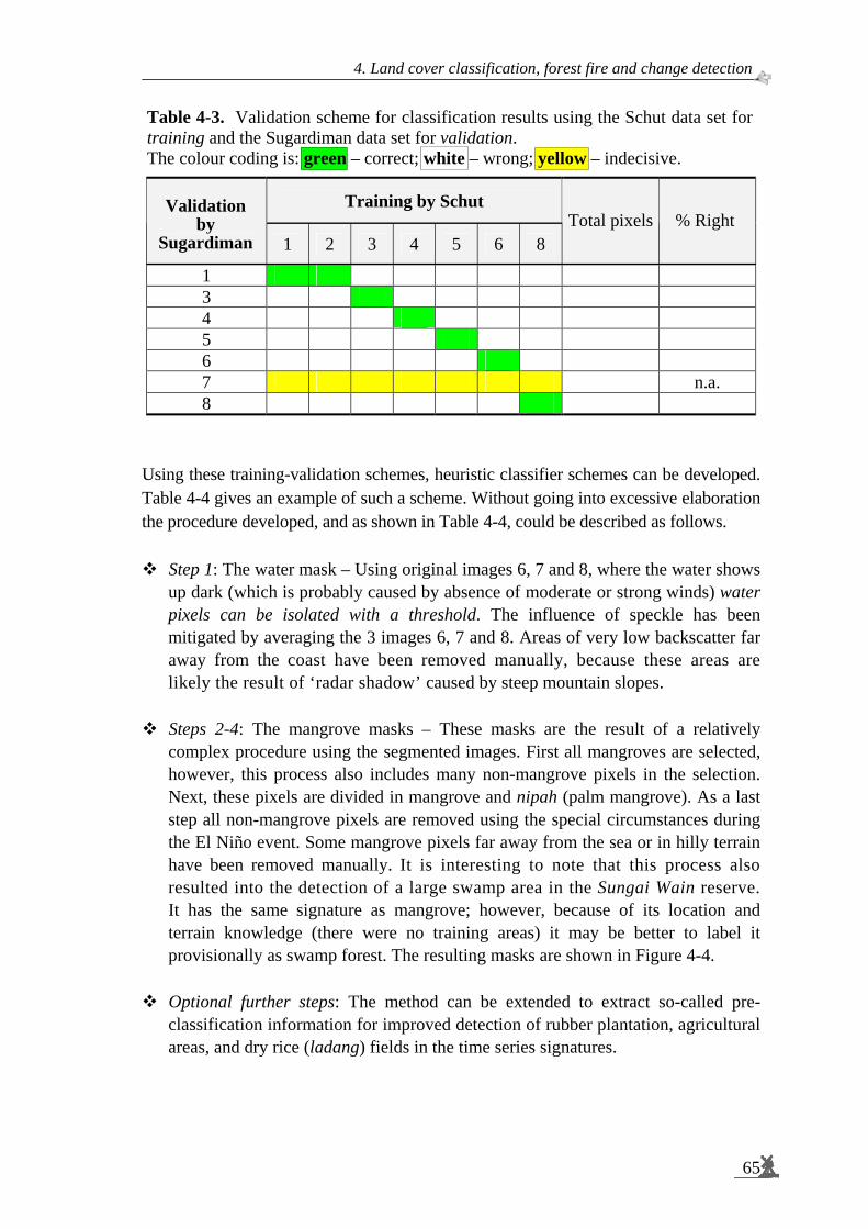
4. Land cover classification, forest fire and change detection
65
Table 4-3. Validation scheme for classification results using the Schut data set for training and the Sugardiman data set for validation. The colour coding is: green – correct; white – wrong; yellow – indecisive.
Training by Schut
Validation by
Sugardiman 1 2 3 4 5 6 8 Total pixels % Right
1 3 4 5 6 7 n.a. 8
Using these training-validation schemes, heuristic classifier schemes can be developed. Table 4-4 gives an example of such a scheme. Without going into excessive elaboration the procedure developed, and as shown in Table 4-4, could be described as follows.
Step 1: The water mask – Using original images 6, 7 and 8, where the water shows up dark (which is probably caused by absence of moderate or strong winds) water pixels can be isolated with a threshold. The influence of speckle has been mitigated by averaging the 3 images 6, 7 and 8. Areas of very low backscatter far away from the coast have been removed manually, because these areas are likely the result of ‘radar shadow’ caused by steep mountain slopes.
Steps 2-4: The mangrove masks – These masks are the result of a relatively
complex procedure using the segmented images. First all mangroves are selected, however, this process also includes many non-mangrove pixels in the selection. Next, these pixels are divided in mangrove and nipah (palm mangrove). As a last step all non-mangrove pixels are removed using the special circumstances during the El Niño event. Some mangrove pixels far away from the sea or in hilly terrain have been removed manually. It is interesting to note that this process also resulted into the detection of a large swamp area in the Sungai Wain reserve. It has the same signature as mangrove; however, because of its location and terrain knowledge (there were no training areas) it may be better to label it provisionally as swamp forest. The resulting masks are shown in Figure 4-4.
Optional further steps: The method can be extended to extract so-called pre-
classification information for improved detection of rubber plantation, agricultural areas, and dry rice (ladang) fields in the time series signatures.
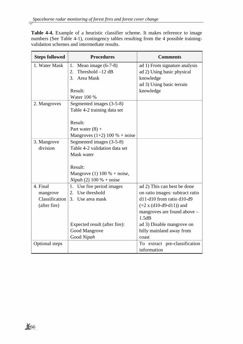
Spaceborne radar monitoring of forest fires and forest cover change
66
Table 4-4. Example of a heuristic classifier scheme. It makes reference to image numbers (See Table 4-1), contingency tables resulting from the 4 possible training- validation schemes and intermediate results.
Steps followed Procedures Comments
1. Water Mask 1. Mean image (6-7-8) 2. Threshold –12 dB 3. Area Mask Result: Water 100 %
ad 1) From signature analysis ad 2) Using basic physical knowledge ad 3) Using basic terrain knowledge
2. Mangroves Segmented images (3-5-8) Table 4-2 training data set Result: Part water (8) + Mangroves (1+2) 100 % + noise
3. Mangrove division
Segmented images (3-5-8) Table 4-2 validation data set Mask water Result: Mangrove (1) 100 % + noise, Nipah (2) 100 % + noise
4. Final mangrove Classification (after fire)
1. Use fire period images 2. Use threshold 3. Use area mask Expected result (after fire): Good Mangrove Good Nipah
ad 2) This can best be done on ratio images: subtract ratio d11-d10 from ratio d10-d9 (=2 x (d10-d9-d11)) and mangroves are found above –1.5dB ad 3) Disable mangrove on hilly mainland away from coast
Optional steps To extract pre-classification information
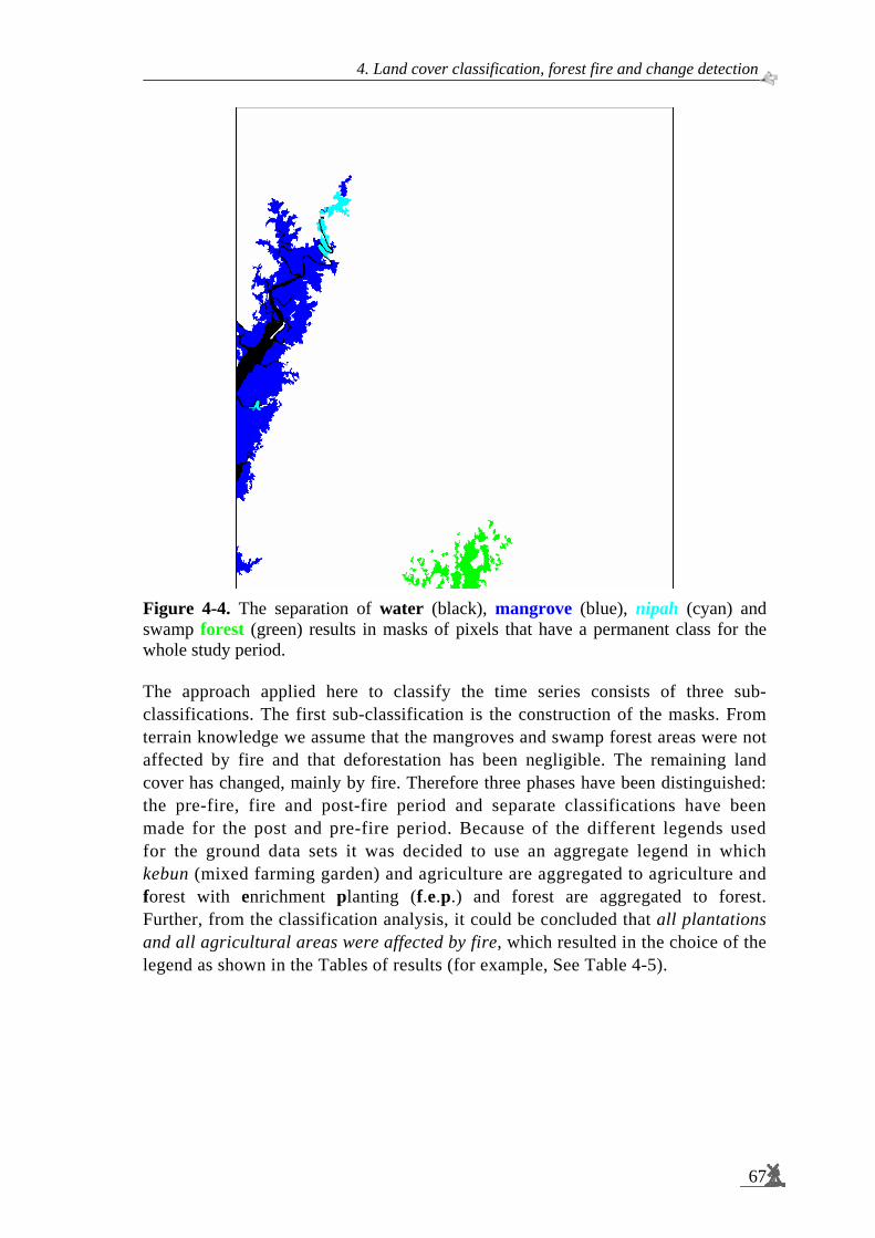
4. Land cover classification, forest fire and change detection
67
Figure 4-4. The separation of water (black), mangrove (blue), nipah (cyan) and swamp forest (green) results in masks of pixels that have a permanent class for the whole study period. The approach applied here to classify the time series consists of three sub-classifications. The first sub-classification is the construction of the masks. From terrain knowledge we assume that the mangroves and swamp forest areas were not affected by fire and that deforestation has been negligible. The remaining land cover has changed, mainly by fire. Therefore three phases have been distinguished: the pre-fire, fire and post-fire period and separate classifications have been made for the post and pre-fire period. Because of the different legends used for the ground data sets it was decided to use an aggregate legend in which kebun (mixed farming garden) and agriculture are aggregated to agriculture and forest with enrichment planting (f.e.p.) and forest are aggregated to forest. Further, from the classification analysis, it could be concluded that all plantations and all agricultural areas were affected by fire, which resulted in the choice of the legend as shown in the Tables of results (for example, See Table 4-5).
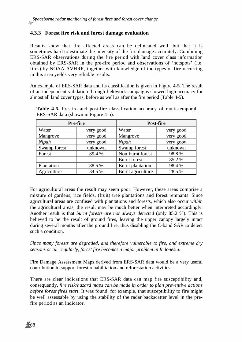
Spaceborne radar monitoring of forest fires and forest cover change
68
4.3.3 Forest fire risk and forest damage evaluation Results show that fire affected areas can be delineated well, but that it is sometimes hard to estimate the intensity of the fire damage accurately. Combining ERS-SAR observations during the fire period with land cover class information obtained by ERS-SAR in the pre-fire period and observations of ‘hotspots’ (i.e. fires) by NOAA-AVHRR, together with knowledge of the types of fire occurring in this area yields very reliable results. An example of ERS-SAR data and its classification is given in Figure 4-5. The result of an independent validation through fieldwork campaigns showed high accuracy for almost all land cover types, before as well as after the fire period (Table 4-5).
Table 4-5. Pre-fire and post-fire classification accuracy of multi-temporal ERS-SAR data (shown in Figure 4-5).
Pre-fire Post-fire Water very good Water very good Mangrove very good Mangrove very good Nipah very good Nipah very good Swamp forest unknown Swamp forest unknown Forest 89.4 % Non-burnt forest 98.8 % Burnt forest 85.2 % Plantation 88.5 % Burnt plantation 98.4 % Agriculture 34.5 % Burnt agriculture 28.5 %
For agricultural areas the result may seem poor. However, these areas comprise a mixture of gardens, rice fields, (fruit) tree plantations and forest remnants. Since agricultural areas are confused with plantations and forests, which also occur within the agricultural areas, the result may be much better when interpreted accordingly. Another result is that burnt forests are not always detected (only 85.2 %). This is believed to be the result of ground fires, leaving the upper canopy largely intact during several months after the ground fire, thus disabling the C-band SAR to detect such a condition. Since many forests are degraded, and therefore vulnerable to fire, and extreme dry seasons occur regularly, forest fire becomes a major problem in Indonesia. Fire Damage Assessment Maps derived from ERS-SAR data would be a very useful contribution to support forest rehabilitation and reforestation activities. There are clear indications that ERS-SAR data can map fire susceptibility and, consequently, fire risk/hazard maps can be made in order to plan preventive actions before forest fires start. It was found, for example, that susceptibility to fire might be well assessable by using the stability of the radar backscatter level in the pre-fire period as an indicator.

4. Land cover classification, forest fire and change detection
69
A B
C D
Legend Pre-fire
Water Nipah Mangrove Swamp Forest Plantation Agriculture
Legend Post-fire Water Nipah Mangrove Swamp Forest Burnt forest Burnt plantation Burnt agriculture
Figure 4-5. ERS-SAR data fragments of the 20 km x 18 km Sungai Wain test site area. A. SAR image of 13 April 1998, B. multi-temporally segmented SAR image of 2 June 1997 (Blue), 13 April 1998 (Green) and 18 May 1998 (Red), C. pre-fire period classification, D. post-fire period classification.
An example for the test area is given in Figure 4-6. More technical details on this technique have been given in Grim et al (2000) and Sugardiman et al (2000). Several features in this image are striking. For example, an evaluation of the pre-fire period, fire risk and the actual damage done reveals that all forests under these extremely dry conditions actually burned, except for the protected forest areas Wanariset, Bukit Bangkirai and Sungai Wain, where active fire fighting took place and for small areas close to the mangroves. The latter may be related to more favourable terrain drainage conditions. Good forest, not actively protected from fires, did burn. An example is the stretch of forest in the lower-left corner between forest plantations. The latter are extremely vulnerable and, apparently the fire easily spreads.
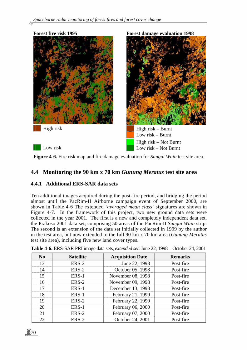
Spaceborne radar monitoring of forest fires and forest cover change
70
Forest fire risk 1995 Forest damage evaluation 1998
Figure 4-6. Fire risk map and fire damage evaluation for Sungai Wain test site area.
4.4 Monitoring the 90 km x 70 km Gunung Meratus test site area
4.4.1 Additional ERS-SAR data sets Ten additional images acquired during the post-fire period, and bridging the period almost until the PacRim-II Airborne campaign event of September 2000, are shown in Table 4-6 The extended ‘averaged mean class’ signatures are shown in Figure 4-7. In the framework of this project, two new ground data sets were collected in the year 2001. The first is a new and completely independent data set, the Prakoso 2001 data set, comprising 50 areas of the PacRim-II Sungai Wain strip. The second is an extension of the data set initially collected in 1999 by the author in the test area, but now extended to the full 90 km x 70 km area (Gunung Meratus test site area), including five new land cover types.
Table 4-6. ERS-SAR PRI image data sets, extended set: June 22, 1998 – October 24, 2001
No Satellite Acquisition Date Remarks 13 ERS-2 June 22, 1998 Post-fire 14 ERS-2 October 05, 1998 Post-fire 15 ERS-1 November 08, 1998 Post-fire 16 ERS-2 November 09, 1998 Post-fire 17 ERS-1 December 13, 1998 Post-fire 18 ERS-1 February 21, 1999 Post-fire 19 ERS-2 February 22, 1999 Post-fire 20 ERS-1 February 06, 2000 Post-fire 21 ERS-2 February 07, 2000 Post-fire 22 ERS-2 October 24, 2001 Post-fire
High risk Low risk
High risk – Burnt Low risk – Burnt High risk – Not Burnt Low risk – Not Burnt

4. Land cover classification, forest fire and change detection
71
(a)
(b) Figure 4-7. Averaged mean temporal signatures derived from ERS data with extended set (without image no. 22 of Table 4-6). The data left of the vertical dotted line has been described in Figure 4-3. At the right side of the vertical dotted line the new data are shown. Note that there is a calibration offset between ERS-1 and ERS-2 data. a. All land cover classes including the class water; b. Without the class water.
Bac
ksca
tter
(dB
)
Image date
Bac
ksca
tter
(dB
)
Image date

Spaceborne radar monitoring of forest fires and forest cover change
72
Table 4-7. One additional new field data set (Prakoso 2001 data set in Hoekman, 2001) for training and evaluation.
Database Prakoso June 2001
Land cover #Regions of Interest Class Water 5 1 Shrimp ponds 6 2 Primary forest 9 3 Mangrove 6 4 Urban area 4 5 Rubber plantation 5 6 Palm oil plantation 4 7 Secondary forest 4 8 Shrub/ Alang-alang 7 9
Total 50
Table 4-8. Extended database (Sugardiman 2001 data set) for training and evaluation.
Database Sugardiman June 2001 Land cover #Regions of Interest Class
Water 11 1 Mangrove 10 2 Forest unburned 4 3 Forest burned 4 4 Agriculture 4 5 Unproductive 4 6 Plantation 6 7 Primary forest 5 8 Secondary forest 5 9 Palm oil plantation 5 10 Grassland 5 11 Logged over forest 5 12 Bare land 5 13
Total 73
4.4.2 A more generalised approach by introducing Iterated Conditional Modes
In the initial approach underlying the results discussed in the Section 4.3 a multi-temporal segmentation technique (Oliver and Quegan, 1998) was utilised prior to a strongly heuristic physically based classification.
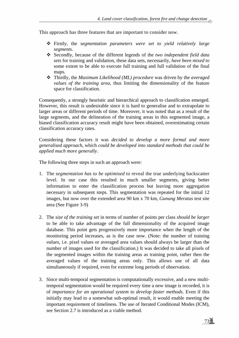
4. Land cover classification, forest fire and change detection
73
This approach has three features that are important to consider now.
Firstly, the segmentation parameters were set to yield relatively large segments.
Secondly, because of the different legends of the two independent field data sets for training and validation, these data sets, necessarily, have been mixed to some extent to be able to execute full training and full validation of the final maps.
Thirdly, the Maximum Likelihood (ML) procedure was driven by the averaged values of the training area, thus limiting the dimensionality of the feature space for classification.
Consequently, a strongly heuristic and hierarchical approach to classification emerged. However, this result is undesirable since it is hard to generalise and to extrapolate to larger areas or different periods of time. Moreover, it was noted that as a result of the large segments, and the delineation of the training areas in this segmented image, a biased classification accuracy result might have been obtained, overestimating certain classification accuracy rates. Considering these factors it was decided to develop a more formal and more generalised approach, which could be developed into standard methods that could be applied much more generally. The following three steps in such an approach were: 1. The segmentation has to be optimised to reveal the true underlying backscatter
level. In our case this resulted in much smaller segments, giving better information to enter the classification process but leaving more aggregation necessary in subsequent steps. This segmentation was repeated for the initial 12 images, but now over the extended area 90 km x 70 km, Gunung Meratus test site area (See Figure 3-9)
2. The size of the training set in terms of number of points per class should be larger
to be able to take advantage of the full dimensionality of the acquired image database. This point gets progressively more importance when the length of the monitoring period increases, as is the case now. (Note: the number of training values, i.e. pixel values or averaged area values should always be larger than the number of images used for the classification.) It was decided to take all pixels of the segmented images within the training areas as training point, rather then the averaged values of the training areas only. This allows use of all data simultaneously if required, even for extreme long periods of observation.
3. Since multi-temporal segmentation is computationally excessive, and a new multi-
temporal segmentation would be required every time a new image is recorded, it is of importance for an operational system to develop faster methods. Even if this initially may lead to a somewhat sub-optimal result, it would enable meeting the important requirement of timeliness. The use of Iterated Conditional Modes (ICM), see Section 2.7 is introduced as a viable method.
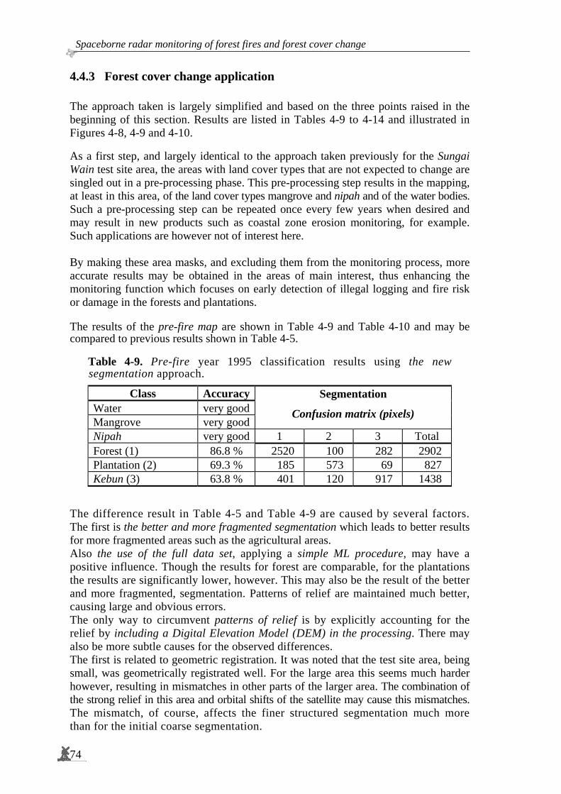
Spaceborne radar monitoring of forest fires and forest cover change
74
4.4.3 Forest cover change application The approach taken is largely simplified and based on the three points raised in the beginning of this section. Results are listed in Tables 4-9 to 4-14 and illustrated in Figures 4-8, 4-9 and 4-10. As a first step, and largely identical to the approach taken previously for the Sungai Wain test site area, the areas with land cover types that are not expected to change are singled out in a pre-processing phase. This pre-processing step results in the mapping, at least in this area, of the land cover types mangrove and nipah and of the water bodies. Such a pre-processing step can be repeated once every few years when desired and may result in new products such as coastal zone erosion monitoring, for example. Such applications are however not of interest here. By making these area masks, and excluding them from the monitoring process, more accurate results may be obtained in the areas of main interest, thus enhancing the monitoring function which focuses on early detection of illegal logging and fire risk or damage in the forests and plantations. The results of the pre-fire map are shown in Table 4-9 and Table 4-10 and may be compared to previous results shown in Table 4-5.
Table 4-9. Pre-fire year 1995 classification results using the new segmentation approach.
Class AccuracyWater very goodMangrove very good
Segmentation
Confusion matrix (pixels)
Nipah very good 1 2 3 Total Forest (1) 86.8 % 2520 100 282 2902 Plantation (2) 69.3 % 185 573 69 827 Kebun (3) 63.8 % 401 120 917 1438
The difference result in Table 4-5 and Table 4-9 are caused by several factors. The first is the better and more fragmented segmentation which leads to better results for more fragmented areas such as the agricultural areas. Also the use of the full data set, applying a simple ML procedure, may have a positive influence. Though the results for forest are comparable, for the plantations the results are significantly lower, however. This may also be the result of the better and more fragmented, segmentation. Patterns of relief are maintained much better, causing large and obvious errors. The only way to circumvent patterns of relief is by explicitly accounting for the relief by including a Digital Elevation Model (DEM) in the processing. There may also be more subtle causes for the observed differences. The first is related to geometric registration. It was noted that the test site area, being small, was geometrically registrated well. For the large area this seems much harder however, resulting in mismatches in other parts of the larger area. The combination of the strong relief in this area and orbital shifts of the satellite may cause this mismatches. The mismatch, of course, affects the finer structured segmentation much more than for the initial coarse segmentation.
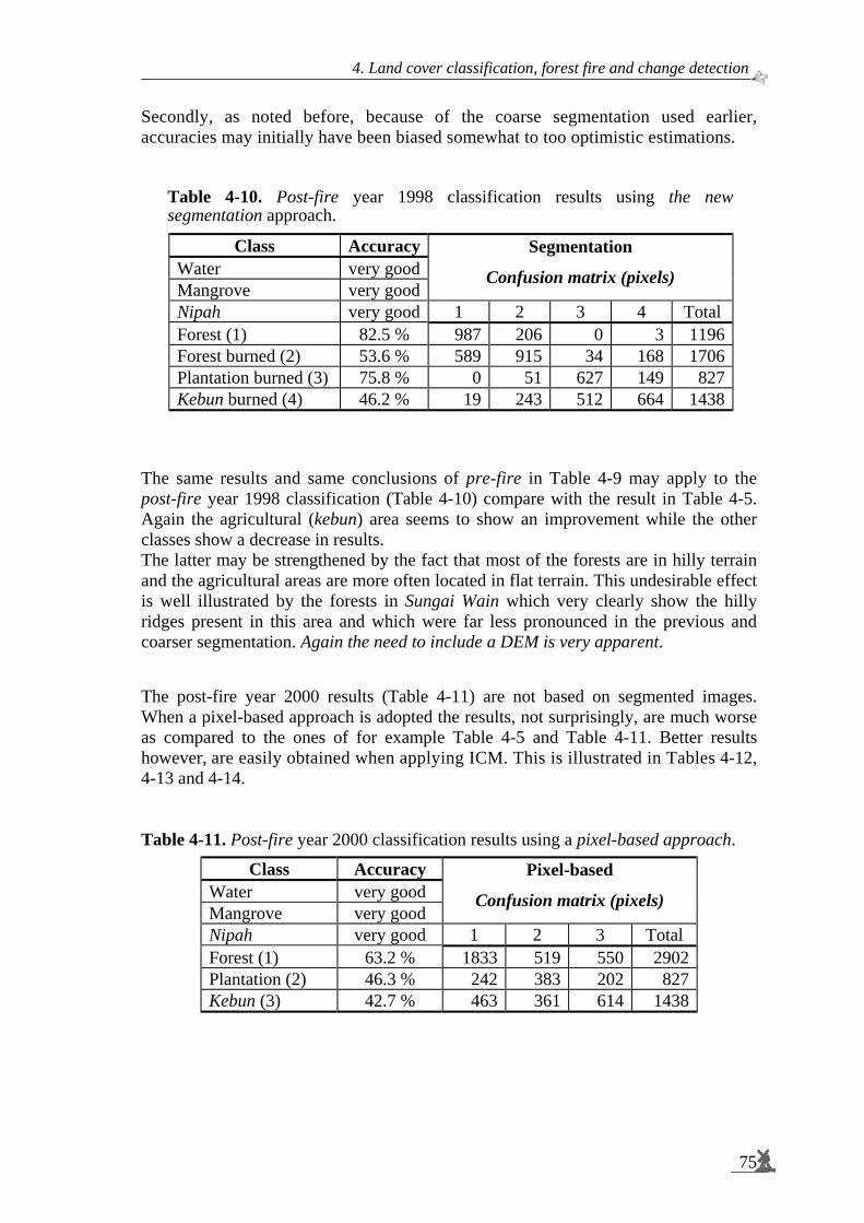
4. Land cover classification, forest fire and change detection
75
Secondly, as noted before, because of the coarse segmentation used earlier, accuracies may initially have been biased somewhat to too optimistic estimations.
Table 4-10. Post-fire year 1998 classification results using the new segmentation approach.
Class AccuracyWater very goodMangrove very good
Segmentation
Confusion matrix (pixels)
Nipah very good 1 2 3 4 Total Forest (1) 82.5 % 987 206 0 3 1196Forest burned (2) 53.6 % 589 915 34 168 1706Plantation burned (3) 75.8 % 0 51 627 149 827Kebun burned (4) 46.2 % 19 243 512 664 1438
The same results and same conclusions of pre-fire in Table 4-9 may apply to the post-fire year 1998 classification (Table 4-10) compare with the result in Table 4-5. Again the agricultural (kebun) area seems to show an improvement while the other classes show a decrease in results. The latter may be strengthened by the fact that most of the forests are in hilly terrain and the agricultural areas are more often located in flat terrain. This undesirable effect is well illustrated by the forests in Sungai Wain which very clearly show the hilly ridges present in this area and which were far less pronounced in the previous and coarser segmentation. Again the need to include a DEM is very apparent. The post-fire year 2000 results (Table 4-11) are not based on segmented images. When a pixel-based approach is adopted the results, not surprisingly, are much worse as compared to the ones of for example Table 4-5 and Table 4-11. Better results however, are easily obtained when applying ICM. This is illustrated in Tables 4-12, 4-13 and 4-14. Table 4-11. Post-fire year 2000 classification results using a pixel-based approach.
Class Accuracy Water very good Mangrove very good
Pixel-based
Confusion matrix (pixels)
Nipah very good 1 2 3 Total Forest (1) 63.2 % 1833 519 550 2902 Plantation (2) 46.3 % 242 383 202 827 Kebun (3) 42.7 % 463 361 614 1438

Spaceborne radar monitoring of forest fires and forest cover change
76
Table 4-12. Post-fire year 2000 classification results using the ICM β=1.0 approach.
Class Accuracy Water very good Mangrove very good
ICM Beta = 1.0
Confusion matrix (pixels)
Nipah very good 1 2 3 Total Forest (1) 83.8 % 2432 196 274 2902 Plantation (2) 64.0 % 187 529 111 827 Kebun (3) 53.7 % 490 176 772 1438
Table 4-13. Post-fire year 2000 classification results using the ICM β=2.0 approach.
Class Accuracy Water very good Mangrove very good
ICM Beta = 2.0
Confusion matrix (pixels)
Nipah very good 1 2 3 Total Forest (1) 85.3 % 2475 178 249 2902 Plantation (2) 63.8 % 185 528 114 827 Kebun (3) 53.2 % 494 179 765 1438
Table 4-14. Post-fire year 2000 classification results using the ICM β=5.0 approach.
Class Accuracy Water very good Mangrove very good
ICM Beta = 5.0
Confusion matrix (pixels)
Nipah very good 1 2 3 Total Forest (1) 86.5 % 2509 175 218 2902 Plantation (2) 62.6 % 197 518 112 827 Kebun (3) 54.3 % 484 173 781 1438
It can be concluded that Iterated Conditional Modes (ICM) techniques results (Tables 4-12 to 4-14) which are comparable to results obtained after application of the multi-temporal segmentation (Table 4-5). That results for forest and plantations are a little worse than in the initial results may be an artefact as discussed above. Explicit application of a DEM may circumvent such problems and eventually result in near optimal results. Apparently segmentation is not a crucial step and may be replaced by ICM techniques. From the results presented here a preference level for the factor β (β1 of Equation 2-6) is not obvious. Evidently this level is not very sensitive and simple and robust methods may emerge. Another big advantage of ICM techniques, besides being simple and computationally fast technique, is that it can easily be expanded utilising other factors, as have been described in Equation 2-6, Section 2.7. Accuracy assessment of the classification was using the discrete multivariate technique so-called KAPPA Analysis (See Appendix D). The Kappa analysis shows that both the ICM and the segmentation approaches yield significantly better results than the pixel-based approach at the 95% confidence interval. As a final illustration of the application of the results a confusion matrix is shown for the forest cover change in the 1995 – 2000 periods in Table 4-15.

4. Land cover classification, forest fire and change detection
77
Table 4-15. Forest cover change in pixels between the years 1995 and 2000 as derived from the field data sets and using the post-fire year 2000 ICM β=5.0 approach.
Class Classification Change Water none Mangrove none Nipah none
Ground Truth 1995
non-forest
non-forest
non-forest
forest
forest
non-forest
forest
forest Total
Forest 182 200 887 1633 2902 Plantation 470 172 115 70 827 Kebun 749 288 226 175 1438
According Table 4-15, 30.6 % (= 887/2902) of the forest is converted into non-forest. Most of the forest remains forest and most of the non-forest remains non-forest (56.3 %). Slight proportions (less than 20 %) of the non-forests are now classified as forest. These areas mainly coincide with the transmigration areas where, apparently, new plantations reach high levels of crown coverage. There are also non-consistent results, such as areas that are forest (in 1999) that are classified as non-forest remaining non-forest. Many of these inconsistent results relate to topographic effects and the mis-classifications very commonly encountered on the slopes facing away from the radar. The hill ridges of Sungai Wain test site area provide a clear example of this behaviour. Another example is the steep slopes of the Meratus mountain chain.
Figure 4-8. Multi-temporal ERS-2 SAR composite extended to the 90 km x 70 km, Gunung Meratus test site area. 02 June 1997 (Blue), 13 April 1998 (Green), 18 May 1998 (Red)

Spaceborne radar monitoring of forest fires and forest cover change
78
Figure 4-9. Post-fire year 1998 classification results of Iterated Conditional Modes (ICM) approaches.
Figure 4-10. Forest cover change map between the years 1995 and 2000: the application of confusion matrix results of Iterated Conditional Modes (ICM) approaches.

4. Land cover classification, forest fire and change detection
79
4.5 Slope correction to improve forest cover classification The availability of the Shuttle Radar Topography Mission (SRTM) Digital Elevation Model (DEM) allowed for study of the effect of slope correction of ERS-SAR data. A simple test was performed on 4 images from the pre-fire period. These images were orthorectified (Section 2.4), optionally slope corrected (Section 2.5) and subsequently filtered using the Gamma maximum a posteriori (Gamma MAP) filter. A straightforward ML pixel-based classification was applied. The results without and with slope correction are shown in the Tables 4-16 and 4-17, respectively. The same procedure was repeated with 4 images of the post-fire period. These results are shown in the Tables 4-18 and 4-19, respectively. The overall result of the pixel-based approach is not very good, and comparable to the pixel-based approach results as earlier shown in the Tables 4-11 to 4-14. Because of changes in methodology, ground data sets used in the orthorectified image, and choice of images, the results are not directly comparable to the Tables 4-11 to 4-14. However, the effect of slope correction can be assessed. This effect is positive, as expected, but the gain in accuracy does not seem to be very high. For the pre-fire situation the overall accuracy increases from 42.5 % to 44.0 % (Tables 4-16 and 4-17). For the post-fire situation this increase is even smaller, i.e. from 49.8 % to 50.0 % (Tables 4-18 and 4-19). It can also be noted that the gain is more pronounced for the forests, which are mainly located in the hilly areas as could be expected from this slope correction approach. For the plantations and kebun areas, which are mainly in flatter areas, the increase is either very small or slightly negative. Table 4-16. Pre-fire ML classification results using 4 images without slope correction. Gamma MAP filtering was applied to reduce the effect of speckle. The pre-fire images used are: 22 October 1993, 26 November 1993, 4 November 1996, and 17 February 1997.
Confusion matrix (pixels) Class Accuracy1 2 3 Total
Forest (1) 45.3 % 11024 37690 89056 Plantation (2) 24.6 % 7383 5847 10539 23769 Kebun (3) 52.4 % 6319 2243 9428 17990
Table 4-17. Pre-fire ML classification results using 4 images with slope correction. Gamma MAP filtering was applied to reduce the effect of speckle.
Confusion matrix (pixels) Class Accuracy1 2 3 Total
Forest (1) 48.0 % 42726 11030 35300 89056 Plantation (2) 24.5 % 7526 5831 10412 23769 Kebun (3) 50.2 % 6671 2281 9038 17990

Spaceborne radar monitoring of forest fires and forest cover change
80
Table 4-18. Post-fire ML classification results using 4 images without slope correction. Gamma MAP filtering was applied to reduce the effect of speckle. The post-fire images used are: 13 April 1998, 18 May 1998, 22 June 1998 and 6 February 2000.
Confusion matrix (pixels) Class Accuracy1 2 3 4 Total
Forest (1) 69.3 % 28700 6886 685 5145 41416 Forest burned (2) 28.7 % 16298 13656 4230 13456 47640 Plantation burned (3) 62.3 % 819 1961 14818 6171 23769 Kebun burned (4) 44.4 % 3601 3374 3025 7990 17990
Table 4-19. Post-fire ML classification results using 4 images with slope correction. Gamma MAP filtering was applied to reduce the effect of speckle.
Confusion matrix (pixels) Class Accuracy1 2 3 4 Total
Forest (1) 69.8 % 28888 6934 639 4955 41416 Forest burned (2) 29.0 % 16189 13835 4190 13426 47640 Plantation burned (3) 61.9 % 797 1951 14704 6317 23769 Kebun burned (4) 44.5 % 3577 3385 3016 8012 17990
To evaluate the above results (Tables 4-16 to 4-19) in some more detail the effect of slope correction on a hilly forest area is shown visually in Figures 4-11a-f. Figure 4-11a shows a small section of the Sungai Wain forest, with the associated histogram in Figure 4-12b a range of roughly 10 dB in the backscatter intensity γ. After slope correction the image and histogram become slightly smoother (Figures 4-11c and 4-11d). The difference image and associated histogram (Figures 4-11e and 4-11f) clearly show that the range of changes is not more than 1 dB, which is far less than the range of 10 dB in the original image. Apparently the magnitude of the correction is not sufficient. When comparing the change image (before and after slope correction) in Figures 4-11e with the original image (Figures 4-11a) it can also be noted that the size of structures of change image is coarser. The results shown in Figure 4-11 explain that the gain in accuracy as presented in the Tables 4.16 to 4.19 is not as high as expected. However, it is still not clear why the slope corrections of ERS-SAR are not sufficient. The algorithm applied showed good performance for the Amazon forest as shown earlier in Section 2.5. Thus, there may be two reasons why the technique fails. The first reason may be the assumption that the dense tropical forest behaves like an opaque isotropic scattering layer. It may be valid for the Amazon forest but may be invalid for the Dipterocarp forests with its large emergent trees (See Appendix A). Secondly, it may be the SRTM DEM itself, which may be too coarse. When it is too coarse hill tops and valleys flatten out, especially when terrain is steep and distances are not large relative to the DEM resolution of 90 m (See Figures 4-12 and 4-13).
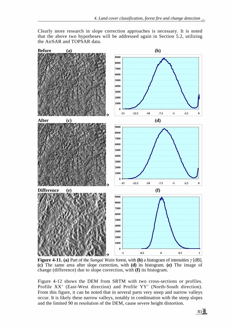
4. Land cover classification, forest fire and change detection
81
Clearly more research in slope correction approaches is necessary. It is noted that the above two hypotheses will be addressed again in Section 5.2, utilizing the AirSAR and TOPSAR data. Before (a) (b)
0
1000
2000
3000
4000
5000
6000
7000
8000
9000
-15 -12.5 -10 -7.5 -5 -2.5 0
After (c) (d)
0
1000
2000
3000
4000
5000
6000
7000
8000
9000
-15 -12.5 -10 -7.5 -5 -2.5 0
Difference (e) (f)
0
1000
2000
3000
4000
5000
6000
7000
8000
9000
-1 -0.5 0 0.5 1
Figure 4-11. (a) Part of the Sungai Wain forest, with (b) a histogram of intensities γ [dB]. (c) The same area after slope correction, with (d) its histogram. (e) The image of change (difference) due to slope correction, with (f) its histogram. Figure 4-12 shows the DEM from SRTM with two cross-sections or profiles. Profile XX’ (East-West direction) and Profile YY’ (North-South direction). From this figure, it can be noted that in several parts very steep and narrow valleys occur. It is likely these narrow valleys, notably in combination with the steep slopes and the limited 90 m resolution of the DEM, cause severe height distortion.

Spaceborne radar monitoring of forest fires and forest cover change
82
Figure 4-12. Digital Elevation Model from the Shuttle Radar Topography Mission image of the Gunung Meratus test site area and two cross-sections. The very steep and narrow distances relative to the DEM resolution will be flatten out in the slope correction process.
Profile XX’
From Pos: 403000.00; 9878950.00 To Pos: 483000.00; 9878950.00
Hei
ght (
m)
Profile YY’
From Pos: 443022.00; 9904000.00 To Pos: 443022.00; 9854000.00
Hei
ght (
m)
1.229 m
1.000 m
750 m
500 m
250 m
0 m -61 m
Y
Y’
X X’
Height (m)
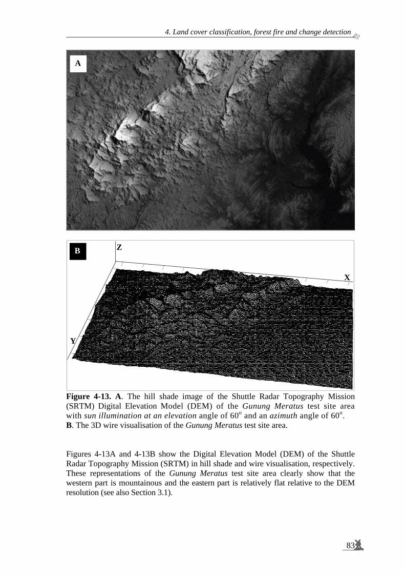
4. Land cover classification, forest fire and change detection
83
Figure 4-13. A. The hill shade image of the Shuttle Radar Topography Mission (SRTM) Digital Elevation Model (DEM) of the Gunung Meratus test site area with sun illumination at an elevation angle of 60o and an azimuth angle of 60o. B. The 3D wire visualisation of the Gunung Meratus test site area. Figures 4-13A and 4-13B show the Digital Elevation Model (DEM) of the Shuttle Radar Topography Mission (SRTM) in hill shade and wire visualisation, respectively. These representations of the Gunung Meratus test site area clearly show that the western part is mountainous and the eastern part is relatively flat relative to the DEM resolution (see also Section 3.1).
Y
X
ZB
A

Spaceborne radar monitoring of forest fires and forest cover change
84
4.6 Textural analysis to enhance forest cover classification Two textural features, with fixed window sizes and displacement lengths have been selected because of the recommendation by Van der Sanden (1997), who successfully explored this technique for forests classification in Guyana using ERS-1 SAR. For further information see also Appendix E. Further refinement of this methodology or adjustment to the different forest structures encountered in Indonesia is out of scope of this study. The effect of adding textural features was investigated using a set of 4 post-fire images of the year 1998. The same classification methodology as in the previous Section 4.5 was used. Textural features were calculated on the first image of this series, after ortho-rectification, slope correction and Gamma maximum a posteriori (Gamma MAP) filtering, resulting in two extra images:
The first textural feature is Grey Level Co-Occurrence Contrast (GLCO-Contrast), with window size 11 x 11 and displacement length 5. The second textural feature is Grey Level Co-Occurrence Correlation (GLCO-Correlation), with window size 11 x 11 and displacement length 1.
Table 4-20 shows the result for the 4 intensity images and Table 4-21 shows the result when the two textural feature images are added to the 4 intensity images. Table 4-20. Post-fire year 1998 pixel-based ML classification results using 4 images with slope correction but without texture. Gamma MAP filtering was applied to reduce the effect of speckle. Images used are: 18 May 1998, 22 June 1998, 5 Oct 1998 and 8 November 1998.
Class Confusion matrix (pixels) Accuracy 1 2 3 4 Total
Forest (1) 47.7 % 19737 6061 4320 11298 41416 Forest burned (2) 21.7 % 18271 10360 6648 12361 47640 Plantation burned (3) 50.7 % 4518 2324 12054 4873 23769 Kebun burned (4) 31.3 % 6683 2672 2997 5638 17990 130815
Table 4-21. Post-fire year 1998 pixel-based ML classification results using 4 images with slope correction and with texture. Gamma MAP filtering was applied to reduce the effect of speckle. The textural features were derived from the 18 May 1998 image after Gamma MAP filtering.
Class Confusion matrix (pixels) Accuracy 1 2 3 4 Total
Forest (1) 87.9 % 36402 3405 36 1573 41416 Forest burned (2) 26.8 % 28235 12775 2059 4571 47640 Plantation burned (3) 43.5 % 4865 4962 10350 3592 23769 Kebun burned (4) 21.8 % 9122 3894 1044 3930 17990 130815

4. Land cover classification, forest fire and change detection
85
The results shown in the Tables 4-20 and 4-21 clearly indicate a significant effect of texture utilization. _The overall accuracy increases from 36.5 % to 48.5 %. Especially for the forest class the effect is large, i.e. it increases from 47.7 % to 87.9 %. However, for the burned plantations and burned kebun, there is a decrease. Apparently, for these classes, which have no fine structure, the use of textural features only adds to confusion. Therefore, textural features may be useful but should be applied with care. As an illustration of the technique these texture transforms are shown as images and associated histograms (Figure 4-14). Intensity (a) (b)
0
500
1000
1500
2000
2500
3000
3500
4000
4500
-25 -20 -15 -10 -5 0 5
Contrast (c) (d)
0
2000
4000
6000
8000
10000
12000
0 50 100 150 200 250 300
Correlation (e) (f)
0
1000
2000
3000
4000
5000
6000
-150 -130 -110 -90 -70 -50 -30 -10 10
Figure 4-14. (a) Part of the Sungai Wain-Inhutani area with (b) a histogram of intensities γ [dB]. (c) Grey Level Co-Occurrence Contrast (GLCO-Contrast) with (d) its histogram. (e) Grey Level Co-Occurrence Correlation (GLCO-Correlation) with (f) its histogram (See also Appendix E).

Spaceborne radar monitoring of forest fires and forest cover change
86
4.7 Coherence of repeat-pass interferometry to improve forest cover classification: an introduction
Single date ERS images tend to show poor separation of forest and non-forest, but multi-temporal composite images offer a significantly improved capability. This is because forest (particularly evergreen forest) has a uniform and relatively high radar backscatter, whereas many non-forest surfaces show temporal variability in backscatter related to seasonal vegetation growth and soil moisture differences. ERS repeat-pass interferometry (particularly using ERS Tandem mission8 data pairs), can provide coherence images which are a valuable source of land cover information (Wegmüller and Werner, 1997). The coherence for repeat-pass interferometry describes the ‘similarity’ of two complex SAR signals. When the two signals are the same, the corresponding coherence is close to one. If the signals are completely different, the coherence values are close to zero. Forest is seen by radar sensors as layers of scatterers (volume scattering by leaves), which reduces the geometric coherence component. Consequently, the tropical forest appears as incoherent. Other surfaces, such as bare surfaces, low vegetation, burnt forest (e.g. remaining trunks without leaves) and buildings tend to have a higher coherence. Excellent results have been obtained in an Indonesian deforestation monitoring study at ESA ESRIN using images generated with the Interferometric Quick Look processor (IQL) processor (Antikidis et al., 1998). Processing of ERS Tandem data from before and after the serious forest fires in 1997 has produced valuable maps of the changes in forest extent. A high degree of correlation has been found with the presence of ATSR hotspots detected during the fire events. Figure 4-15 is a full resolution ERS repeat-pass interferometric image of the Sungai Wain test site area, obtained using ERS tandem images of May 1996. The colour composite of coherence and backscatter intensity images shows forest areas in green, and non-forest in red/yellow colours. There is a good correspondence between the forest areas mapped using multi-temporal data (Figure 4-5 in Section 4.3), and work is continuing to compare fully the results obtained using the two different processing techniques.
8 The ERS Tandem mission consists of two satellites: ERS-1 and ERS-2. The ERS-1 and ERS-2
are flying in the same orbital plane with an inclination of about 98.5 degrees to the Earth's equatorial plane, giving the satellites visibility of all areas of the Earth as it rotates beneath them. Each satellite's pattern of orbital tracks over the Earth's surface repeats itself exactly after a certain number of days. This 'repeat-cycle' depends upon the altitude of the orbit; ERS-1 and ERS-2 are both flying at the same mean altitude of 785 km, providing a repeat-cycle of 35 days (See also Table 3-5). With the current orbital configuration, ERS-2 follows ERS-1 with an approximate delay (called the orbit phasing of the two satellites) of 35 min. Because of this delay and the Earth's rotation, the ground-track patterns of ERS-2 are shifted westwards with respect to those of ERS-1. The orbit phasing has been adjusted to ensure that ERS-2 track over the Earth's surface coincides exactly with that of ERS-1 24 hour’s earlier or 1 day difference (Duchossois & Martin, 1995). Position shift of ERS-1 and ERS- 2 has a consequence on the baseline orientation and baseline length (See also Section 2.6).

4. Land cover classification, forest fire and change detection
87
Figure 4-15. ERS repeat-pass Interferometric image of a 40 km x 40 km area in the Sungai Wain test site area East Kalimantan, with Area C marked as the Inhutani area. Tandem mission image pairs dates 12 May 1996 and 13 May 1996. (Coherence-Red; ERS-2 backscatter Intensity-Green).
4.8 Discussion on NOAA-AVHRR hotspots observations To be able to improve the evaluation of the results given in the previous sections, it is useful to link these results to the available fire hotspots maps. The AVHRR sensors on board of the NOAA Polar Orbiting Satellite are conventionally used in monitoring land/forest fires. In particular, the 3.8 mm infrared band (band 3) is used in hotspot detection. The visible band (band 1) and the near infrared band (band 2) of the same sensor can provide information about the aerosols characteristics and distribution of the smoke. Figure 4-16 shows typical hotspots distribution maps derived from the AVHRR images acquired in January, February, March, April and May 1998 over the test site. These images follow a short period of rainfall in December 1997. The start of the rains around mid-April halted the fires, which clearly show up by the absence of fire hotspots in the May 1998 image.

Spaceborne radar monitoring of forest fires and forest cover change
88
Figure 4-16. Hotspots distribution maps of the 3 test site area derived from the NOAA-AVHRR sensor: A. January 1998; B. February 1998; C. March 1998, D. April 1998; E. May 1998; and F. Accumulated over the period January – May 1998 on top of the ERS-1 image dated 13 April 1998. The boxes indicate the ERS-1 frame, the 90 km x 70 km Gunung Meratus test site, the 20 km x 18 km Sungai Wain test site and the AirSAR, PacRim-II test site area (See Figure 3-9).
A B
C
E F
D

4. Land cover classification, forest fire and change detection
89
Figure 4-17. The same map as in Figure 4-16F, but without the ERS-1 SAR image background.
There are well-known limitations of the use of AVHRR images in fire monitoring. The resolution of the images is coarser than 1 km, hence the precise location of the fire spots cannot be determined. Band 3 of the sensor saturates at an effective temperature around 315 K (42 °C)9. A pixel can be detected as a hotspot pixel either due to a small but intense fire anywhere within the 1-km2 pixel or by a large extent of the warm land surface. Reflection from high-albedo land surface, clouds or sea water can produce false alarms in hotspot detection. Due to these limitations, AVHRR hotspot images tend to overestimate the burnt area but underestimate the number of fires. There are more factors that limit fire detectability. For example, dense clouds or smoke layers can prevent detection because of attenuation of the heat radiation signal. It is also obvious that ground fires, under a still largely intact canopy, are hard to detect. In Chapter 5.3 the ERS-SAR fire damage mapping results will be evaluated using these AVHRR data.
9 Kelvin (K)/ degree Celsius (°C) conversions: Kelvin = degree Celsius + 273.15

Spaceborne radar monitoring of forest fires and forest cover change
90
4.9 Peat swamp forest monitoring: operational implementation Information needs. Programmes of the Indonesian Government, the Borneo Orang-utan Survival Foundation (BOS), the Gibbon Foundation (GF) and the World Wildlife Fund (WWF) are in need of fast and reliable information on land cover change and the locations of illegal logging. For example, in Central-Kalimantan data are needed by BOS and WWF for, respectively, the Mawas and Sebangau peat swamp forest areas (Figure 4-18), for continued improved safeguarding of remaining wild orang-utan populations and their habitat. In principle, the methodology developed and tested for the Gunung Meratus area has a wide applicability. Already in the year 2002 this methodology seemed to be sufficiently mature to apply it for these peat swamp forest areas. Support was given by the present author to the set-up of a prototype system based on ERS-SAR and ENVISAT ASAR. This system initially focused on fast delivery of information on the location of suspected illegal logging and encroachment sites. Because the Mawas and Sebangau areas are perfectly flat areas, the relief problems encountered in the Gunung Meratus area are not present. Moreover, the focus here is on detection of illegal logging. Land cover changes are not very likely. Some variation in time however is to be expected in relation with reforestation programs and drainage characteristics. The latter is partly natural and may support classification in a range of natural forest types. Other parts of this area are (or were) drained by canals and may suffer drought, followed by loss of forest trees, especially on the so-called peat domes. The change detection approach therefore is directed both to the fast detection of illegal logging as well as to land cover change, the latter being supportive to the first. In the future the system could be extended to provide additional information needed by local managers on the state of forest and land cover, reforestation, forest regeneration and degradation and fire susceptibility and damage.
Figure 4-18. Mawas and Sebangau peat swamp forest areas; the boxes indicate the ENVISAT ASAR frames.
Mawas
Sebangau
-2°00’ -2°00’
-3°30’ -3°30’
-113°30’ -115°00’
-113°30’ -115°00’
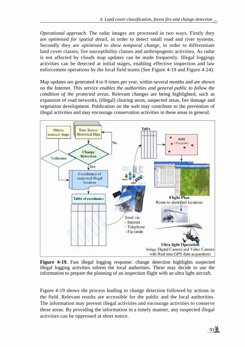
4. Land cover classification, forest fire and change detection
91
Operational approach. The radar images are processed in two ways. Firstly they are optimised for spatial detail, in order to detect small road and river systems. Secondly they are optimised to show temporal change, in order to differentiate land cover classes, fire susceptibility classes and anthropogenic activities. As radar is not affected by clouds map updates can be made frequently. Illegal loggings activities can be detected at initial stages, enabling effective inspection and law enforcement operations by the local field teams (See Figure 4-19 and Figure 4-24). Map updates are generated 4 to 8 times per year, within several months and are shown on the Internet. This service enables the authorities and general public to follow the condition of the protected areas. Relevant changes are being highlighted, such as expansion of road networks, (illegal) clearing areas, suspected areas, fire damage and vegetation development. Publication on the web may contribute to the prevention of illegal activities and may encourage conservation activities in these areas in general.
Figure 4-19. Fast illegal logging response: change detection highlights suspected illegal logging activities inform the local authorities. These may decide to use the information to prepare the planning of an inspection flight with an ultra light aircraft. Figure 4-19 shows the process leading to change detection followed by actions in the field. Relevant results are accessible for the public and the local authorities. The information may prevent illegal activities and encourage activities to conserve these areas. By providing the information in a timely manner, any suspected illegal activities can be oppressed at short notice.

Spaceborne radar monitoring of forest fires and forest cover change
92
Methodology. The methodology adopted for operational application is an extension of the approach reported already for the Gunung Meratus test site area (See Section 4.4). This methodology features several new elements, which are mainly directed to improved detection of very small areas of change. The first new element relates to refined geometrical registration (Vrielink, 2005). For this purpose the area is divided in terrain blocks of 5 km x 5 km (Figure 4-20). New SAR scenes are divided in overlapping radar blocks of 7.5 km x 7.5 km, centred at the same locations. Afterwards these radar blocks are located in fine geometrical registration using auto-focussing techniques. These registrated radar blocks are stacked as input for the change detection algorithm (Figure 4-21). The resulting changes are mapped into the land blocks. These land blocks are put together to create multi-temporal change maps, to be dealt with in See Section 4.10.
Figure 4-20. Block scheme layout for the Mawas area, which is indicated in red. At the left the location of ENVISAT ASAR frames can be seen. At the right the 5 km x 5 km block scheme is superimposed (in green).

4. Land cover classification, forest fire and change detection
93
Figure 4-21. Examples of a multi temporal stack of image blocks or slices.
The second new element relates to the detection of change. Changes in backscatter intensity, expressed in dB, are thresholded per pixel at a maximum of +/- 3dB. Subsequently, these changes are modified by taking into account the changes found in the spatial neighbourhood as well as in the previous observations in time. The latter takes into account seasonal changes. This approach allows for a considerable false alarm reduction in the detection of small areas of changes. The latter are the possible areas of suspected illegal logging (Vrielink, 2005). An example of spatial changes, expressed in empirically derived confidence levels, is shown in Figure 4-22.
Figure 4-22. Change detection results of the ICM algorithm at different scales: light grey: 70 % – 80 %, dark grey: 80 % – 90 % and black: > 90%
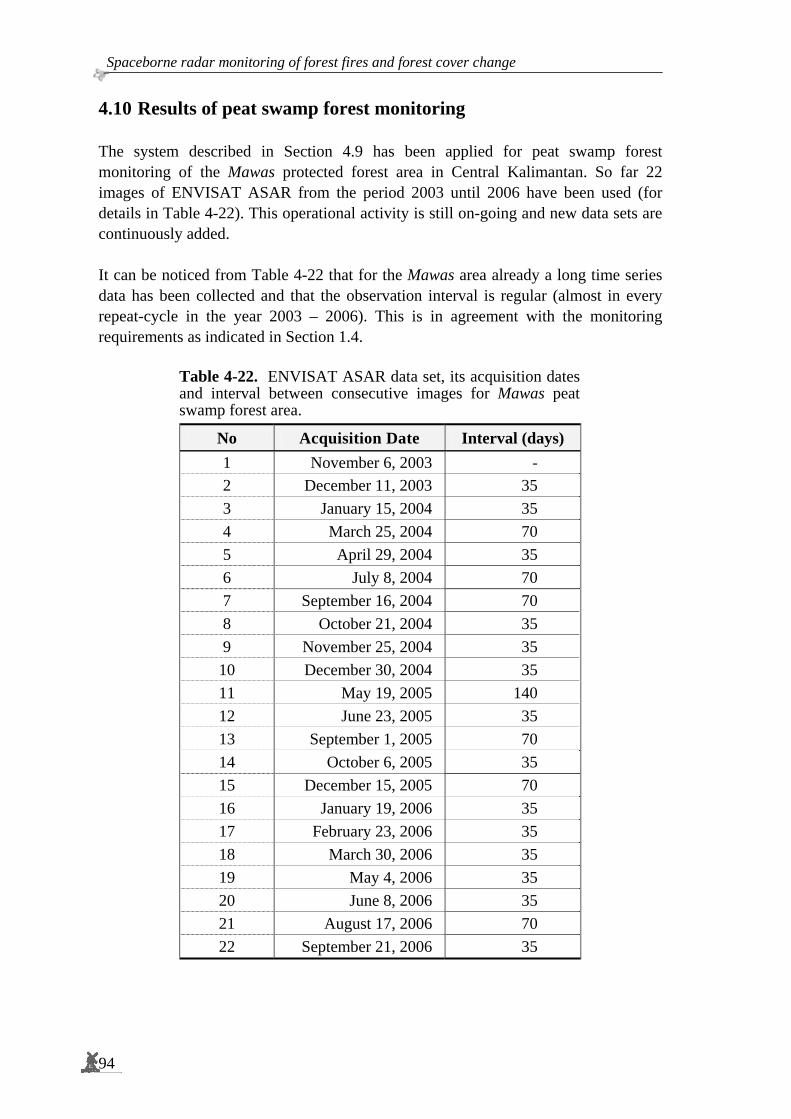
Spaceborne radar monitoring of forest fires and forest cover change
94
4.10 Results of peat swamp forest monitoring The system described in Section 4.9 has been applied for peat swamp forest monitoring of the Mawas protected forest area in Central Kalimantan. So far 22 images of ENVISAT ASAR from the period 2003 until 2006 have been used (for details in Table 4-22). This operational activity is still on-going and new data sets are continuously added. It can be noticed from Table 4-22 that for the Mawas area already a long time series data has been collected and that the observation interval is regular (almost in every repeat-cycle in the year 2003 – 2006). This is in agreement with the monitoring requirements as indicated in Section 1.4.
Table 4-22. ENVISAT ASAR data set, its acquisition dates and interval between consecutive images for Mawas peat swamp forest area.
No Acquisition Date Interval (days) 1 November 6, 2003 - 2 December 11, 2003 35 3 January 15, 2004 35 4 March 25, 2004 70 5 April 29, 2004 35 6 July 8, 2004 70 7 September 16, 2004 70 8 October 21, 2004 35 9 November 25, 2004 35 10 December 30, 2004 35 11 May 19, 2005 140 12 June 23, 2005 35 13 September 1, 2005 70 14 October 6, 2005 35 15 December 15, 2005 70 16 January 19, 2006 35 17 February 23, 2006 35 18 March 30, 2006 35 19 May 4, 2006 35 20 June 8, 2006 35 21 August 17, 2006 70 22 September 21, 2006 35

4. Land cover classification, forest fire and change detection
95
As an example of change detection, Figure 4-23 shows a small part of the Mawas area (one 7.5 km x 7.5 km block; See Section 4.9) where some changes between two image blocks, acquired at 15 January 2004 and 25 March 2004, were found.
Figure 4-23. Part of the Mawas area with some changes between two dates of acquisition. Top left and top middle: ENVISAT ASAR intensity image; Top right: Change image. Below: Blow-up of details. The land cover change detection results from this system are entered into a GIS as polygon layers which have as attributes its pair of acquisition dates and the interval time. After some additional topological post-processing steps the results are merged and an accurate polygons layer of the detected areas of change for the whole Mawas area is generated. An example is shown in Figure 4-24.

Spaceborne radar monitoring of forest fires and forest cover change
96
a. Polygon layer of detected areas of land cover change has been generated from a series of 22 ENVISAT ASAR images. The block scheme of 5 km x 5 km is also displayed.
b. Polygon layer of detected areas of land cover change super-imposed on top of the ENVISAT ASAR image of 21 October 2004
c. Polygon layer of detected areas of land cover change super-imposed on top of an image of Landsat TM 15 February 2003.
Figure 4-24. Polygon layer of detected areas of change over the Mawas area. The results of change detection monitoring using ENVISAT ASAR enables location of suspected areas of illegal logging. (a) Changes on top of a 5 km x 5 km block scheme; (b) land cover changes on top of the 21 October 2004 ENVISAT ASAR image and (c) land cover changes on top of the 15 February 2003 Landsat TM image. Note: Different polygon colours indicate different periods of change.
Zoom in, see next figure.
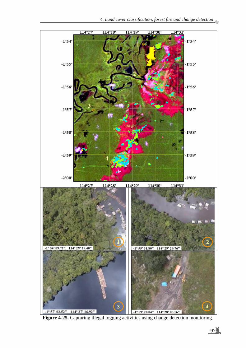
4. Land cover classification, forest fire and change detection
97
Figure 4-25. Capturing illegal logging activities using change detection monitoring.
1 2
3 4

Spaceborne radar monitoring of forest fires and forest cover change
98
Note for Figure 4-25. Top: Detail of image of detected changes on top of a Landsat image. Bottom: Four geocoded video captures showing evidence of illegal logging.
With this information inspection flights with an ultra light aircraft can be planned. These aircrafts are equipped with a Global Positioning System (GPS) connected to a digital video camera. In case illegal logging is confirmed the geocoded video shots provide evidence for the local police (See Table 4-23 and Figure 4-25). Subsequently, an integrated illegal logging response team can inspect the identified sites on the ground, make arrests and confiscate equipment. The actual time between overpass of the satellite and the arrest for the example shown here, was only 4 days.
Table 4-23. Identified illegal logging positions recorded by a Global Positioning System and a Digital Video Camera during the ultra light aircraft survey on 11 March 2004.
Photo No Latitude Longitude
1 -1° 54’ 09.72” 114° 29’ 29.40”
2 -1° 55’ 31.80” 114° 29’ 20.76”
3 -1° 57’ 02.52” 114° 27’ 16.92”
4 -1° 59’ 20.04” 114° 28’ 05.16”
Besides in Mawas, the system has been introduced recently in the Sebangau National Park, a large peat swamp forest area not far from Mawas area. An example is shown in Figure 4-26. The yellow area in the small black box shows accumulated changes over the years 2003 until November 2004. After inspection by ultra light aircraft it became evident that this is an area with forest collapse. Drought caused by excess drainage through a canal constructed by illegal loggers causes ground fires, which burned the roots of trees, causing them to fall down. Apparently ENVISAR ASAR is a suitable sensor to follow such processes.

4. Land cover classification, forest fire and change detection
99
Figure 4-26. Forest cover change detection map of the Sebangau National Park; B. Zoom in to a large detected area of change (yellow and orange polygons on Landsat background image); C. Ultra light aircraft survey aerial photograph confirms the change and shows that is caused by collapsed trees. 4.11 Summary and conclusions Radar monitoring of the Sungai Wain test site area has been carried out within three phases of research. Initially, a large number of ERS-SAR scenes acquired in the 1993 – 1996 period of the East-Kalimantan Tropenbos test site were studied in support of the INDonesian Radar Experiment (INDREX-96). The objective was to study its potential for land cover change monitoring. Subsequently, an additional series of ERS-SAR scenes was acquired in support of studies to assess fire damage caused by the severe El Niño event, occurring at the same test site in the period June 1997 – April 1998. Finally, another series of ERS-SAR data was acquired to extend the period until the year 2001 and in wider area, the Gunung Meratus test site area, thus including the time of the PacRim-II NASA airborne radar data acquisition campaign.
C B
A
i
ii
Spaceborne radar monitoring of forest fires and forest cover change
100
The severe fire period appeared to be the single most important event causing change. Multi-temporal images including dates of the fire period dramatically show the magnitude of the damage done (Section 4.2). Initial validation study at 20 km x 18 km Sungai Wain test site area. Results of radar monitoring were presented on different temporal sub-sets of the data, and with different objectives. The first study results relate to the Sungai Wain test site area, which 20 km by 18 km is a sub-set of the total study area, over the period 1993 – 1998, thus including the El Niño fire event. The classification procedure developed here is strongly heuristic and hierarchical and utilizes physical features of the test site, terrain knowledge, the available ground truth and special physical circumstances such as wind (at the sea surface) and the severe drought during the El Niño event. Thus, the methodology is not straightforwardly applicable in other areas or for other time series. On the other hand, it clearly illustrates the importance of physical knowledge and utilization of special circumstances. In principle, the longer the time series the more information can be extracted. However, longer time series show more land cover change, making the number of possible land cover change sequences progressively (exponentially) larger. Hence it becomes more difficult to select simple legends to describe the longer history. Two independently acquired ground data sets have been used alongside. Though they use a slightly different legend they could be used alternatively as validation set and training set. The approach applied to classify the time series consists of three sub-classifications. The main sub-classification is the construction of spatial masks. From terrain knowledge it can be assumed that the mangroves and swamp forest areas were not affected by fire and that deforestation has been negligible. The remaining land cover has changed, mainly by fire. Therefore three phases have been distinguished: the pre-fire, (during) fire and post-fire period and separate classifications have been made for the post and pre-fire period. Results show that fire affected areas can be delineated well, but that it is sometimes hard to estimate the intensity of the fire damage accurately. The result of an independent validation through fieldwork campaigns showed high accuracy (ranging from 85.2 % to 98.8 %) for almost all land cover types, before as well as after the fire period. For agricultural areas the result may seem poor (34.5 % pre-fire and 28.5 % post-fire). However, these areas comprise a mixture of gardens, rice fields, (fruit) tree plantations and forest remnants. Since agricultural areas are confused with plantations and forests, which also occur within the agricultural areas, the result may be much better when interpreted accordingly. Another result is that burnt forests are not always detected (only 85.2 %). This is believed to be the result of ground fires, leaving the upper canopy largely intact during several months after the ground fire, thus disabling the C-band SAR to detect such a condition.

4. Land cover classification, forest fire and change detection
101
There are clear indications that ERS-SAR data can map fire susceptibility and, consequently, fire risk/hazard maps can be made in order to plan preventive actions before forest fires start. It was found, for example, that susceptibility to fire might be well assessable by using the stability of the radar backscatter level in the pre-fire period as an indicator. An evaluation of the pre-fire period fire risk and the actual damage done reveals that all vulnerable forests areas under these extremely dry conditions actually burned except for the protected forest areas Wanariset, Bukit Bangkirai and Sungai Wain, where active fire fighting took place. Monitoring 90 km x 70 km Gunung Meratus test site area. The second study relates to the Gunung Meratus test site area, which is a 90 km by 70 km area. It utilizes 10 additional images, thus extending the study period to 1993 – 2001. It was then decided to develop a more formal and more generalised approach, which could be developed into standard methods that could be applied much more generally. Important issues to allow for fast and accurate processing were considered. In the first place it was recognized that the segmentation should be optimised to reveal the true underlying backscatter level. Here, it resulted into smaller segments as compared to the first study. Secondly, since multi-temporal segmentation is computationally excessive, and a new multi-temporal segmentation would be required every time a new image is recorded, it is of importance for an operational system to develop faster methods, even if this initially may lead to a somewhat sub-optimal result. In this research the use of ICM has been introduced as a viable method. The results of Gunung Meratus test site area study have been compared to the results of the Sungai Wain study discussed above. Differences in the pre-fire classification are caused by several factors. The first is the better and more fragmented segmentation which leads to better results for more fragmented areas such as the agricultural areas. Though the results for forest are comparable, for the plantations the results are significantly lower, however. This may also be the result of the better, more fragmented, segmentation. Patterns of relief are maintained much better, causing large and obvious errors. The only way to circumvent this is by explicitly accounting for the relief by including a DEM in the processing. The same results and same conclusions may apply to the post-fire year 1998 classification. Again the agricultural (kebun) area seems to show an improvement while the other classes show a decrease in results. The latter may be strengthened by the fact that most of the forests are in hilly terrain and the agricultural areas are more often located in flat terrain. This undesirable effect is well illustrated by the forests in Sungai Wain which very clearly show the hilly ridges present in this area and which were far less pronounced in the previous and coarser segmentation. Again the need to include a DEM is very apparent. The post-fire year 2000 results are not based on segmented images. When a pixel-based approach is adopted the results, not surprisingly, are much worse as compared to the ones discussed above. Good results, however, are easily obtained when applying ICM.
Spaceborne radar monitoring of forest fires and forest cover change
102
It may be concluded that this simple and computationally fast technique yields results which are comparable to results obtained after application of the multi-temporal segmentation. That results for forest and plantations are a little worse than in the initial results may be an artefact as discussed above. Explicit application of a DEM may circumvent such problems and eventually result in near optimal results. Apparently segmentation is not a crucial step and may be replaced by ICM techniques. The Kappa analysis shows that both the ICM and the segmentation approaches yield significantly better results than the pixel-based approach at the 95 % confidence interval. Slope correction. The effect of slope correction using the assumption that the forest behaves as a uniform opaque isotropically scattering layer has been assessed. This effect is positive, as expected, but the gain in accuracy does not seem to be very high. Further study showed that the induced slope correction is around 1 dB while values up to 10 dB were expected. Thus, there may be two causes why the technique fails. The first cause is the assumption that the dense tropical forest behaves like an opaque isotropic scattering layer. It may be valid for the Amazon forest but may be invalid for the Dipterocarp forests with its large emergent trees. Secondly, it may be the SRTM DEM itself, which may be too coarse. When it is too coarse hill tops and valleys flatten out, especially when terrain is steep and distances are not large relative to the DEM resolution of 90 m. The results would be that corrections are too small, which is the case, and spatial features of slope correction are too coarse than the actual structures, which is also the case. Note that the latter problem has been addressed in a later stage of this study using the higher spatial resolution AirSAR data and AirSAR DEM of the same test area. Textural analysis of radar images. Utilization of textural features yields a significant improvement of overall classification accuracy, which increases from 36.5 % to 48.5 %. Especially for the forest class the effect is large, i.e. it increases from 47.7 % to 87.9 %. However, for the burned plantations and burned kebun, there is a decrease. Apparently, for these classes, which have no fine structure, the use of textural features only adds to confusion. Therefore, textural features may be useful but should be applied with care. Coherence of repeat-pass interferometry. The additional use of SAR repeat-pass interferometry has been discussed. Because of temporal decorrelation its use seems to be primarily limited to data of the ERS-1/ERS-2 tandem-mode or to specific conditions, such as severe fire damage. NOAA-AVHRR hotspots are a valuable additional data source for forest fire studies.
4. Land cover classification, forest fire and change detection
103
Peat swamp forest monitoring. Programmes of the Indonesian Government, the Borneo Orang-utan Survival Foundation (BOS), the Gibbon Foundation (GF) and the World Wildlife Fund (WWF) are in need of fast and reliable information on land cover change and the locations of illegal logging. For example, in Central-Kalimantan data are needed by BOS and WWF of respectively the Mawas and Sebangau peat swamp forest areas, for continued improved safeguarding of remaining wild orang-utan populations and their habitat. In principle, the methodology developed and tested for the Gunung Meratus area has a wide applicability. Already in the year 2002 this methodology seemed to be sufficiently mature to apply it for these peat swamp forest areas. Support was given by the author to the set-up of a prototype system based on ERS-SAR and ENVISAT ASAR. This system initially focused on fast delivery of information on the location of suspected illegal logging and encroachment sites. Results of peat swamp forest monitoring. With this information inspection flights with ultra light aircrafts can be planned. These aircrafts are equipped with Global Positioning System (GPS) connected to a digital video camera. In case illegal logging is confirmed the geocoded video shots provide evidence for local police. Subsequently, an integrated illegal logging response team can inspect the identified sites on ground, make arrests and confiscate equipment. The actual time between overpass of the satellite and the arrests in the field, for the example of Mawas area shown in this thesis, was only 4 days. Accumulated changes over the years 2003 until November 2004 in the Sebangau National Park were studied. After inspection by ultra light aircraft it became evident that this is an area with forest collapse. Drought caused by excess drainage through a canal constructed by illegal loggers causes ground fires, which burned the roots of trees, causing them to fall down. Apparently ENVISAR ASAR is a suitable sensor to follow such processes.

C h a p t e r
5 ______________________________________________
5 IMPLEMENTATION OF SAR MONITORING FOR INDONESIAN FORESTRY:
OUTLOOK TO THE FUTURE In this final chapter the utility of other radar systems with different characteristics as well as future satellite radar missions will be discussed in order to make recommendations for implementation at the Indonesian Ministry of Forestry. In Section 5.1 a comparison is made between the performance of airborne L- and P-band radar acquired with AirSAR and the performance of spaceborne C-band radar for fire scar detection at the Sungai Wain test site area. The AirSAR simultaneously acquired a high-resolution DEM, which allows for a better evaluation of the difficulties encountered with slope correction in Section 4.5. In Section 5.2 the results of the studies as presented in Chapter 4 and in Section 5.1 will be compared with results from literature. Using these insights, a discussion on the combination of techniques using different sensor types and a range of scales is presented in Section 5.3. Section 5.4 gives a brief overview of some relevant future Synthetic Aperture Radar (SAR) missions that will be carried out. Finally, a recommendation for future implementation at the Ministry of Forestry is given in Section 5.5.
5.1 Fire scar detection in airborne L- and P-band and the use of high-resolution DEM
The Airborne Synthetic Aperture Radar (AirSAR) experiment carried out at the Sungai Wain test site area in September 2000, 2 years after the period of intense fires, enables a comparison between the performances of the spaceborne C-band of the ERS-SAR, as reported in Chapter 4, with the capabilities of C-, L- and P-bands of AirSAR data. Another advantage of the AirSAR data is its much higher resolution. This also applies for the InSAR DEM that was acquired simultaneously with the TOPSAR instrument (See e.g. Prakoso, 2006). In the Sungai Wain reserve 9 transects of 400 m long and 20 m wide have been mapped, each centred at the transition of the unburned - the burned area. Using this information 10 radar intensity samples were taken in the burned part and 10 samples in the unburned part. The results are shown in Figures 5-1 and 5-2. In the L-band as well as in the P-band there is a clear distinction between burned and unburned forest parts. In the C-band there is however no contrast at all.
105

Spaceborne radar monitoring of forest fires and forest cover change
106
These findings can be explained by the type of fire that occurred here, namely ‘ground fire’, and the physics of radar interaction. C-band reflection is high when a layer of green leaves is present. L- and P-band radiations penetrate deeper and reflection is high when (living) trunks are present. Ground fire destroys the lower layers and damages trunks, causing trees to die slowly. Most of the tree crowns keep green leaves for a time, while in the mean time a dense regrowth at the ground surface occurs. Consequently a sufficiently thick layer of leaves is always present obscuring the damage for observation by C-band radar.
Figure 5-1. Detail of the burned forest network in the Sungai Wain Reserve and its relation to topography. (A) Polarimetric radar image in orthographic projection with intensity corrections for slope effects: blue C-band, green L-band, red P-band. Vegetation types: yellow unburned forest, pink burned forest, blue severely burned rubber plantation. Note that large trees are distinguishable in both forest types. (B) The high-resolution Digital Elevation Model (DEM) of the same area: grey-scale from low (black) to high (white) altitude of terrain plus vegetation. (C) Map of the same area based on visual interpretation of the airborne SAR-image and on information from the field (Source Figure 5-1c: Eichhorn, 2006) Another interesting result is the effect of slope correction. The high-resolution of InSAR DEM of TOPSAR DEM was used. The effect of the correction can be seen when comparing Figures 5-2 and 5-3. It is evident that after slope correction the distinction between burned and unburned areas increases both in L- as well as P-band. For all bands, both for the burned and unburned cases, there is a significant decrease in the range of backscatter levels. This indicates that slope correction with a higher resolution Digital Elevation Model (DEM) is better than in the case of Chapter 4.5 where ERS data where corrected with the low resolution Shuttle Radar Topography Mission (SRTM) digital elevation model. Thus, it may be concluded that the resolution of the digital elevation model is an important factor for the correction of relief in ERS-SAR data.
A B C

5. Implementation of SAR monitoring for Indonesian forestry: outlook to the future.
107
-8.0
-7.0
-6.0
-5.0
-4.0
-3.0
-2.0
-1.0
0.0
0 1 2 3 4 5 6Cases
Inte
nsity
[dB
]
Figure 5-2. Radar intensity (Total Power) extracted from the orthorectified image with slope correction in C-, L- and P-band of AirSAR for 10 sample areas in burned forest and 10 sample areas in unburned forest. _Cases: (1) P-band burned, (2) P-band unburned, (3) L-band burned, (4) L-band unburned, (5) C-band burned and (6) C-band unburned.
-8.0
-7.0
-6.0
-5.0
-4.0
-3.0
-2.0
-1.0
0.0
0 1 2 3 4 5 6Cases
Inte
nsity
[dB
]
Figure 5-3. Radar intensity (Total Power) extracted from the orthorectified image without slope correction in C-, L- and P-band of AirSAR for 10 sample areas in burned forest and 10 sample areas in unburned forest. Cases: (1) P-band burned, (2) P-band unburned, (3) L-band burned, (4) L-band unburned, (5) C-band burned and (6) C-band unburned.
P
C
L
P
C
L

Spaceborne radar monitoring of forest fires and forest cover change
108
On the other hand it is still not entirely clear whether the proposed model for slope correction is appropriate here. For example, when a small section of the AirSAR image is inspected (See Figure 5-4) it is clear that the forest does not resemble a continuous layer. At the slopes facing away from the radar isolated bulbs of backscatter on an intense dark background are visible. Such a layer may behave physically very different from the uniform isotropic layer that was successfully applied in Guyana (Section 2.5). Clearly, more research in relief correction algorithms for different tropical forest types may be very useful. Original image After slope correction
Figure 5-4. The left image is the original C-, L- and P-band of AirSAR Total Power. The right image is after slope correction. Slopes facing the radar (magenta arrow) appear very different from slopes facing away from the radar (black arrow). As an example, the use of AirSAR data for fire damage assessment and natural regeneration application is noted. The AirSAR image data reveals a network of interconnected patches of unburned remnant forest (Figure 5-1c). These patches are mainly located in the valleys, which always remain wetter. Such networks cannot be observed by spaceborne ERS-SAR but are well visible using AirSAR observation. These networks of patches were also found at other test area covered by the AirSAR. A local study in the Sungai Wain area (Eichhorn, 2006) revealed that this network was mainly composed of infrequent species. This is in contrast with the burned areas which are mainly composed of abundant species. The biodiversity therefore seems to be well conserved, and this was even the case in some twice-burnt areas, after an initial fire in the 1982 El-Niño. Subsequent destructive human activities like ‘salvage-felling’, rather than El-Niño fires themselves, seem to be the major threat to the forests´ biological diversity.

5. Implementation of SAR monitoring for Indonesian forestry: outlook to the future.
109
5.2 Limitations of short time series in spaceborne C-band for fire scar detection
It is interesting to compare the various results in order to illustrate the effects of differences in methodology and the utility of other sensors. Figure 5-5 displays a collection of images in geometrical registration which, at the same time, presents an overview of results discussed before. Figure 5-5a and 5-5b show the ERS-SAR pre-fire and post-fire classification results of Section 4.3, displayed on a background Landsat image of 25 December 2000, being shown in Figure 5-5c. The C-, L- and P-band Total Power AirSAR image, which has been discussed in Section 5.1, is shown in Figure 5-5d. Figure 5-5e shows the coinciding section of the NOAA-AVHRR hotspot image discussed in Section 4.8. Figure 5-5f shows the coinciding small section of the map published by Siegert et al (2001). Careful inspection of these 6 sub-images of Figure 5-5 reveals the following. The fire damage map discussed in Section 4.3 (Figure 5-5b) is in good agreement with both the Landsat and the AirSAR images. The remaining forest is classified well as unburnt forest by C-band of ERS-SAR, and even some of the ground fire patches in the Sungai Wain periphery, probably the most intense ones show up. The healthy forests show high stability in radar backscatter over seasons and years because of its dense canopy and, consequently, are less susceptible to drying of the litter layer and ground fire. As explained above, most of the ground fires remain undetected in spaceborne C-band of ERS-SAR. They only show up well in the L- and P-band in the AirSAR image, but also in the Landsat image which was collected almost two years after the fires. The NOAA-AVHRR data show that no fires were detected in the zone of ground fires. Consequently, to map ground fires in a fast way, i.e. independent of cloud cover, a sensor like the L-band ALOS PALSAR (See Chapter 5.4) would be very suitable nowadays. The results presented by Siegert et al (2001) in the same area show that the large areas of fire damage detected with the C-band ERS-SAR relate to heavier forms of damage and, therefore, in general, are not in contradiction with the findings presented in Section 4.3. The plantations are classified as heavy fire damage. In fact this is true but the biomass level was already very low. The results mainly disagree for the Sungai Wain forest. The remaining completely intact forest is classified as having a 20 – 50 % damage level. The results shown in Section 4.3 and Section 4.4 are much more realistic. Maybe this is a consequence of the different approaches, or a result of tuning with local ground truth. Nevertheless, analysis of longer multi-temporal or time series, as was done in this study, is to be preferred above a simple change detection based on two images, as was done by Siegert et al (2001). The longer time series takes many pre-fire observations into account, which, when combined with a hierarchical and physical approach, reveals a much better description of the forest status.

Spaceborne radar monitoring of forest fires and forest cover change
110
a. ERS-SAR Classification Pre-fire b. ERS-SAR Classification Post-fire
c. Landsat 5 TM d. AirSAR C-, L-, and P-band Total Power
e. NOAA-AVHRR hotspot series f. Fire damage classification of GTZ
Figure 5-5. A collection of different images in geometrical registration of the Sungai Wain test site area. The legends of the images are shown at the next page.

5. Implementation of SAR monitoring for Indonesian forestry: outlook to the future.
111
Legend of georeferenced images of the Sungai Wain test site area (18 km x 20 km): a. ERS-SAR Classification Pre-fire b. ERS-SAR Classification Post-fire
Water Nipah Mangrove Swamp Forest Plantation Agriculture
Water Nipah Mangrove Swamp Forest Burnt forest Burnt plantation Burnt agriculture
c. Landsat 5 TM Path-Row: 116-61 date 25 December 2000
d. AirSAR PacRim-II C-, L-, and P-band Total Power July – October 2000
e. NOAA AVHRR hotspot series January 1998 February 1998 March 1998 April 1998 May 1998
f. Fire damage classification of GTZ, IFFM (Siegert et al., 2001)
Mangrove
Primary forest
Secondary forest
Shrub, bush
Grassland, Dryland agricultural
Bare land
20 – 50% damage 50 – 80% damage >80% damage, biomass mostly sustained >80% damage, biomass mostly burned
Mangrove
Primary forest
Primary forest burnt
Secondary forest
Shrub, bush
Grassland, Dryland agricultural
Bare land

Spaceborne radar monitoring of forest fires and forest cover change
112
5.3 The advantages of a multi-sensor advanced radar remote sensing system
Application of the spaceborne Synthetic Aperture Radar remote sensing is the focal point of this study, particularly its application in monitoring of land cover and tropical rainforest dynamics in East Kalimantan, Indonesia. With the objective to develop an operational system it is opportune to review the basic components of an ideal remote sensing system, as formulated by Lillesand and Kiefer (2000): it should have a uniform energy source which will provide energy over all wavelengths in irrespective of time and place and non-interfering by atmosphere. This will be a compact sensor, yielding spatially detailed data throughout the spectrum. In this system, it will be processed into an interpretable format on instantaneously (real time data handling) and providing timely information. Because of the consistent nature of the energy, there will be no need for reference data in the analytical procedure. The same set of data will become various forms of information for different users, because of their vast knowledge about the particular earth resources being used. Some of those components well comply with radar specifications, however, based on experiences from several experiments and campaigns in the tropics region, which have been described in Sections 1.3 and 1.4, contemplating several categories of user needs and the derived system specifications, it was concluded that: “No single advanced radar remote sensing system could be the optimal solution to meet all information needs”. A survey of what is available or could be made available by development of new systems led to the following conclusion concerning the implementation of an operational system for forest monitoring and management: “Several dedicated systems for different categories of application and for different phases of operation may be a much more realistic approach”. This was also confirmed by the User Requirements Study for FAME (Forest Assessment and Monitoring Environment), which was executed by a study team co-ordinated by the International Institute for Aerospace Survey and Earth Sciences (ITC). The study focused on identification of the requirements for an improved information supply mechanism in the form of an “end-to-end” information system (De Gier et al., 1999). Although no specific inventory was yet made for Indonesia, the outcome of this study is assumed to be applicable for Indonesia as well. The study of De Gier et al., 1999 concluded that information on land and forest cover (including general land use classes such as agriculture) and forest degradation have the highest priority at all user levels. Other forest themes mentioned are: forest function allocation, forest types, forest health, bio-diversity, and biomass for carbon sequestration, forest products and stand parameters. Forest fire themes include fire detection, fire damage assessment and fire hazard assessment (Grim et al., 2000). There are also significant differences in the required scales of information. The required scale is usually very much related to the size of the area of interest. This is however not automatically related to the level at which organisations operate. The area of interest of a province of a large country may be the same as that for a

5. Implementation of SAR monitoring for Indonesian forestry: outlook to the future.
113
national level organisation in a small country (e.g. the area of the East Kalimantan Province equals five times the area of The Netherlands). There is a tendency for a decrease in the need for precision and detail of information when going from local to global levels. In this respect it would be desirable if information could be aggregated from the lower to higher user levels. This aggregation of information is however currently has not done yet, and is often neither possible nor feasible. The required update frequency of spatial information is apparently more related to the theme of the information than the level at which the information is needed. Information on forest production and stand parameters for selected areas are basically needed on annual basis. When forest fire damage assessment is concerned, information updates are usually required every 1 to 3 months. In the case of forest fire detection however, information is required on a daily basis. Information on land and forest cover and land use and vegetation/forest types need a variety of update frequencies ranging from 1 to every 5 or 10 years. So-called advanced remote sensing systems for forest monitoring will involve the use of both spaceborne and airborne remote sensing systems (Figure 5-6). Spaceborne (satellite) systems will be used for ‘full’ monitoring activities, which cover the large Indonesian forest areas completely and produce comprehensive classes. It can be done once or twice a year at national and/or regional level. Spaceborne systems are able to direct airborne surveys by identifying places of interest, thus avoiding unnecessary operations. With airborne systems it is possible to conduct detailed monitoring in order to derive 'advanced' products (e.g. tree maps), 'where or when' it is necessary. Since the areas of forest in Indonesia are quite large such overall monitoring system i.e. full monitoring followed by detailed monitoring is appropriate system for Indonesian forestry.
Figure 5-6. Advanced radar remote sensing systems for forest monitoring. Full monitoring activities will use spaceborne systems for larger forest areas; being done ’once or twice’ per year at national and/or regional level. Spaceborne systems are able to direct airborne surveys by identifying places of interest. With airborne systems it is possible to conduct detailed monitoring 'where or when' it is necessary to derive 'advanced' products (such as tree maps).
‘where and when’it’s necessary
‘once or twice’per year
ERS, ENVISAT
Spaceborne
Full Monitoring
Land / ForestCover Map
Ground survey
AirSAR
Airborne
Detailed Monitoring
Tree Map (Automatically derived)

Spaceborne radar monitoring of forest fires and forest cover change
114
Applications of Synthetic Aperture Radar data Synthetic Aperture Radar (SAR) is a very versatile technique for environmental monitoring and survey. Its application is diverse, including provision of information of the atmosphere (e.g. rain fall mapping), the behaviour of oceans (e.g. monitoring of current, wind at the ocean surface), bathymetry, oil spill detection and sea ice mapping. Nowadays it also includes topics such as monitoring of deformation of active volcanoes, (sub-canopy) flooding, soil moisture and vegetation. Its potential relevance for tropical rainforest mapping and inventory strongly depends on the types of radar and platform used. An overview is shown in Table 5-1. Table 5-1. Spaceborne and airborne information products and their relation to radar systems and user requirements for forestry.
SPACEBORNE AIRBORNE SYSTEMS REQUIREMENTS Short Wave Long Wave High resolution
and Short Wave Long Wave
Detailed Inventory - - Tree maps,
Topography
Forest type, Flooding conditions, Vegetation height
Monitoring Indicators of Sustainable Management
Illegal clear-cut detection, Timber road network expansion
Land degradation,Secondary re-growth
Tree extraction, Skid trails, Reforestation
Land degradation Secondary re-growth
Fire Risk and Fire Damage Assessment
Plant/soil moisture content, Loss of green biomass
- Plant/soil moisture content, Canopy closure
-
Map Updating Change detection, Topography (Scale 1:100,000)
Biomass classes, Land cover change
Scale 1:5,000–1:25,000
Biomass classes, Land cover change
Combined approach Though each of the above-mentioned techniques has its own intrinsic value for meeting information needs, it is worthwhile to study how these can be combined efficiently within an operational monitoring environment. The fact that certain systems are already operationally available, while other systems are either planned, proposed or experimental, makes it necessary to differentiate between short term and long term solutions. In Figure 5-7 four levels (I – IV) of radar observation are distinguished, related to an increasing spatial scale and a decreasing observation frequency and coverage. At the lowest level very frequent observations (several times per week) at medium satellite resolution is achieved, completely covering the area of interest (e.g. an entire country).

5. Implementation of SAR monitoring for Indonesian forestry: outlook to the future.
115
Examples of systems at this level could be ENVISAT ASAR in “Wide Swath” mode. In “Wide Swath” mode ENVISAT ASAR could detect areas of special interest, which could be subsequently monitored at level II using high satellite resolution at a lower observation frequency (roughly once per month) to update mapping or detail selected areas of interest. Already a lot of information could be obtained using ENVISAT ASAR high-resolution images for applications such as forest fire risk, forest damage evaluation (in this thesis), monitoring the expansion of the timber road network and the progress of strip cutting and the detection of small areas (less then 1 ha) of illegal clear-cut (Van der Sanden, 1997; this thesis Section 4.10). When proper use is made of level II information, airborne radar flights can be planned much more efficiently. Airborne radar, at high resolution, can be applied to efficiently map large areas in detail (See also Van der Sanden and Hoekman, 1999). An example is the ‘250,000 km2 protected forest area’ mapping campaign executed by Dornier in Indonesia in 1996. Similar images (from the INDREX-96 campaign) also appeared to be useful to accurately check strip cutting and enrichment planting activity. Systems with larger wavelengths (L- and P-band) may appear very useful for mapping forest and land cover type, biomass and forest flooding. At the highest level (IV) individual trees, instead of land cover units, are observed and requires a short-wave very-high resolution interferometric airborne SAR. This system can be operated in areas with legal logging activities and in areas of special interest identified through the first three levels of observation. On the other hand, when level IV data are available, these could contribute to mapping accuracy by combining the information with level III mapping systems.
Figure 5-7. Efficient data acquisition is obtained by a multi-sensor and multi-platform approach. In this example medium to high resolution spaceborne Synthetic Aperture Radar (SAR) is used to monitor large areas and to select areas of interest where high to very-high resolution airborne Synthetic Aperture Radar (SAR) can be directed to collect detailed information.
Satellite100 m resolution
Airborne1.5 m resolution
Airborne3 m resolution
Satellite25 m resolution
Spaceborne 100 m
Spaceborne25 m
Airborne3 m resolution
I II III Level IV
Airborne 1.5 m resolution

Spaceborne radar monitoring of forest fires and forest cover change
116
5.4 Future Spaceborne Synthetic Aperture Radar sensors Future availability of spaceborne satellite Synthetic Aperture Radar (SAR) images data is necessary for continuous operation of the forest monitoring system that has been developed in this study. Several satellites can be considered as successors of the current satellites, i.e. ERS-1, ERS-2, and ENVISAT. Details of successors those satellites are given in the Appendix H. In this study several spaceborne and airborne SAR data sources such as ERS-1, ERS-2, ENVISAT, AirSAR and SRTM have been used. A summary of their characteristics is given in Table 5-2. Table 5-2. Summary of characteristics of present SAR sensors that have been used in this study.
Characteristics ERS-1 & ERS-2 ENVISAT AirSAR SRTM
Availability 1991 – 2008 2002 – 2010 2000 2002 Band C-band C-band C-,L- & P-band C-, X-band Polarization VV VV, HH, HV HH,VH,HV,VV HH,HV,VH,VVResolution 33 m 28 m 4 m 90 m Swath Width 100 km > 100 km 10 – 60 km 111 km Incidence Angle 19 – 26° 14 – 45° 25 – 60° 30 – 60° & 54°Repeat-cycle 35 days 35 days - - DEM - - 10 m 90 m
Table 5-7 summaries of the characteristics of future SAR sensors, which will be available to ensure continuity of the present SAR data sources. Table 5-3. Summary of the characteristics of future SAR sensors.
Characteristics PALSAR TerraSAR-X TanDEM-X SENTINEL-1
Launch date 24 January 2006
27 February 2007
Expected in 2009
Expected in 2011
Band L-band X-band X-band C-band Polarization HH,HV,VH,VV HH,VV,HV,VH HH,VV,HV,VH VV,VH,HH,HVResolution 7 – 100 m 1 – 16 m 1 – 16 m 4 – 20 m Swath Width 20 – 350 km 10 – 150 km ≥ 30 km 20 – 400 km Incidence Angle 8 – 60° 20 – 55° 25 – 50° ?° Repeat-cycle 46 days 11 days 11 days 12 days DEM - - 12 m -
Note: There are still other missions available for examples the SAR-Lupe (X-band), COSMO-SkyMed (X-, C- , L- and P-band), and RADARSAT-2 (C-band).
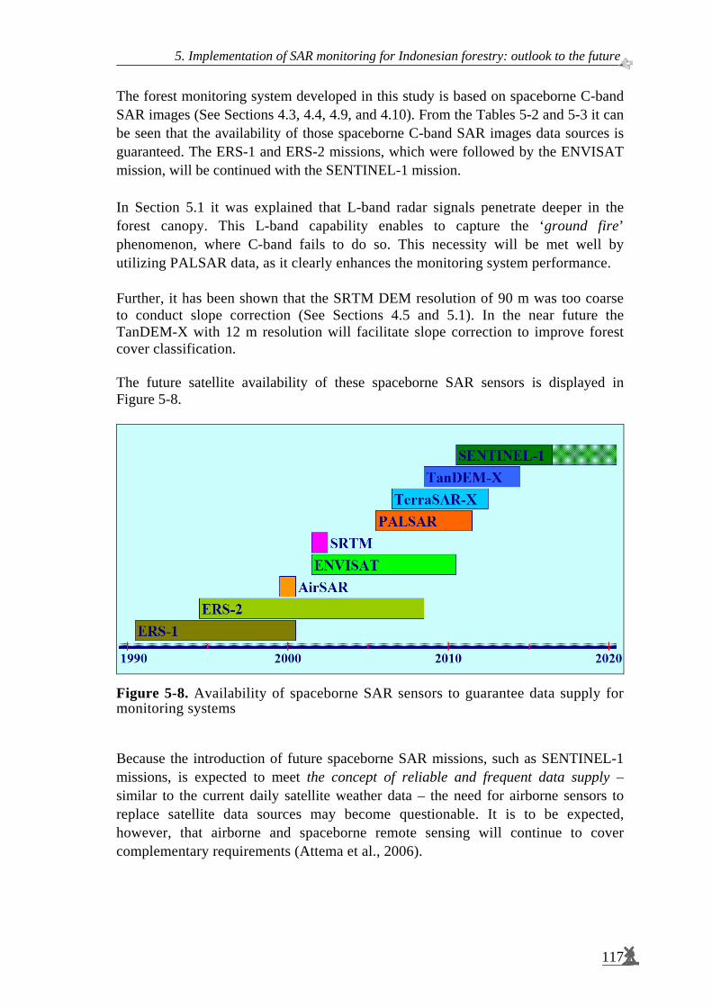
5. Implementation of SAR monitoring for Indonesian forestry: outlook to the future.
117
The forest monitoring system developed in this study is based on spaceborne C-band SAR images (See Sections 4.3, 4.4, 4.9, and 4.10). From the Tables 5-2 and 5-3 it can be seen that the availability of those spaceborne C-band SAR images data sources is guaranteed. The ERS-1 and ERS-2 missions, which were followed by the ENVISAT mission, will be continued with the SENTINEL-1 mission. In Section 5.1 it was explained that L-band radar signals penetrate deeper in the forest canopy. This L-band capability enables to capture the ‘ground fire’ phenomenon, where C-band fails to do so. This necessity will be met well by utilizing PALSAR data, as it clearly enhances the monitoring system performance. Further, it has been shown that the SRTM DEM resolution of 90 m was too coarse to conduct slope correction (See Sections 4.5 and 5.1). In the near future the TanDEM-X with 12 m resolution will facilitate slope correction to improve forest cover classification. The future satellite availability of these spaceborne SAR sensors is displayed in Figure 5-8.
Figure 5-8. Availability of spaceborne SAR sensors to guarantee data supply for monitoring systems Because the introduction of future spaceborne SAR missions, such as SENTINEL-1 missions, is expected to meet the concept of reliable and frequent data supply – similar to the current daily satellite weather data – the need for airborne sensors to replace satellite data sources may become questionable. It is to be expected, however, that airborne and spaceborne remote sensing will continue to cover complementary requirements (Attema et al., 2006).

Spaceborne radar monitoring of forest fires and forest cover change
118
5.5 Implementation for Indonesian forestry For the implementation of radar monitoring systems in Indonesian forestry, there are two factors to be taken into consideration i.e. forest land uses classification and the forestry institutions. Forests in Indonesia are classified into various uses i.e. for the production of timber and non-timber, for the protection of hydrological functions and for the conservation of living resources and ecological functions (See also Section 3.8). While the management of production forests are conducted by the state enterprises and the private companies, the protected and conservation forest classes are managed by the government in collaboration with the organizations of non-government. They include local communities such as the traditional 'adat' organizations, national and also international organizations. The authority to regulate the management is distributed hierarchically following the unified system of the government. The national government formulates forest policy by developing forest planning, while at the same time controlling the policy through various regulations and e.g. its organizations to implement their policies. The local governments implement these policies and regulations to ensure sustainable uses of forests in the country. The ongoing decentralization policy transfers the authority from the national to the local level governments. In the forestry, the policy should be supported with direct and transparent procedures as well as uncomplicated accessibility of monitoring information. This study has investigated and presented new techniques for forest monitoring systems. They proved to be fairly accurate and robust (See Section 4.4); to be applied to other areas (See Section 4.9); to be reproduced using different data sets (See Section 4.10); moreover the continuity of spaceborne SAR data sources will be guaranteed (See Section 5.4). Those prominences of the monitoring system will allow speeding up the ongoing policy decentralization (See Nugroho, 2006). The techniques to monitor forests have been further developed. This study establishes the systematic capability to provide the evaluation of forest fire risk and forest damage, forest cover changes and change detection for fast illegal logging response. These capabilities are required by Indonesian MOF to enhance its performance, particularly in the Regional Offices and in the National Park authorities to monitor and observe the remaining tropical rainforest in the country. Certainly these capabilities should exist also in the Head Quarters in order to be able to provide reliable information on the national forest condition. Further on to formulate a consistent regulation (i.e. technical guideline, instruction manual or handbook) for representative offices throughout Indonesia. At national level these capabilities are included in the Forest Monitoring and Assessment System (FOMAS) as well as in the Forest Management Information System (FMIS).
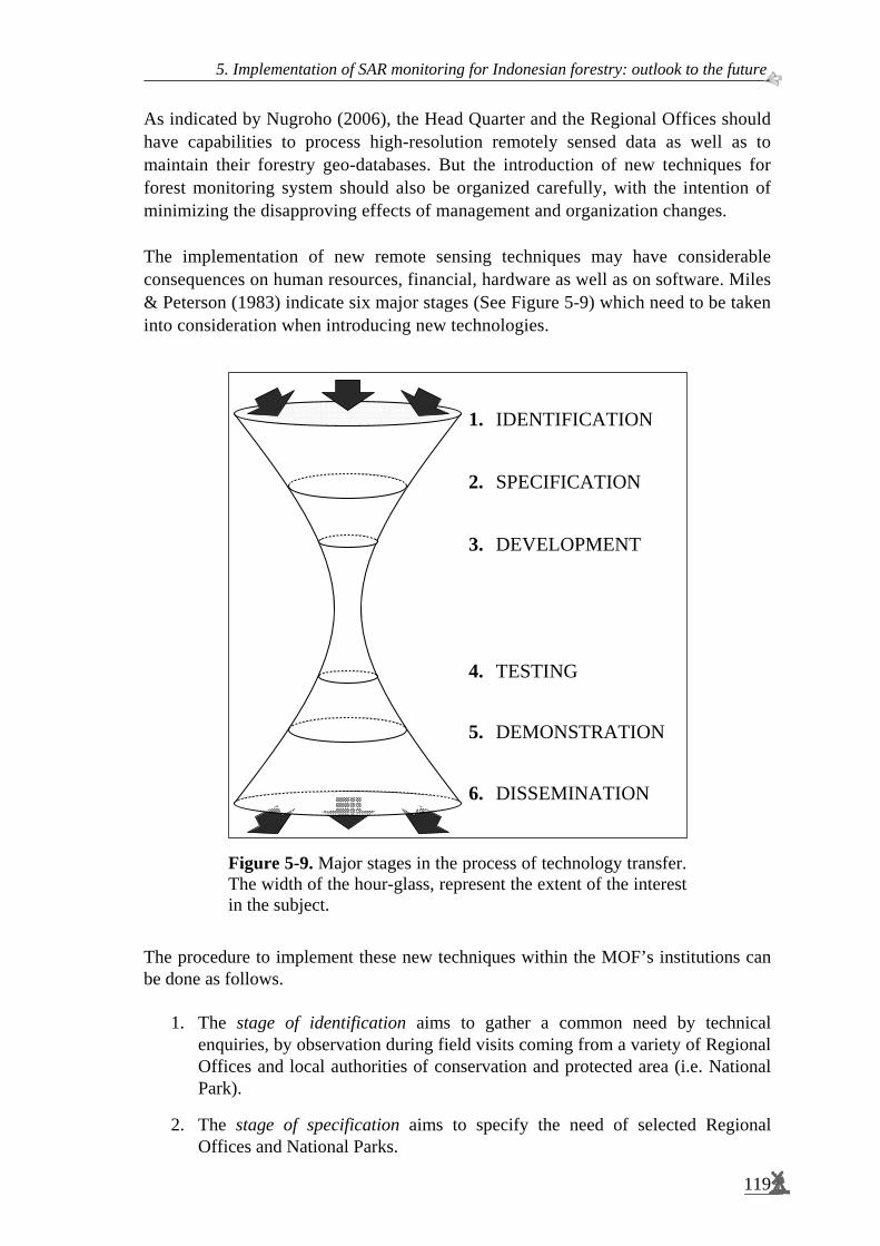
5. Implementation of SAR monitoring for Indonesian forestry: outlook to the future.
119
As indicated by Nugroho (2006), the Head Quarter and the Regional Offices should have capabilities to process high-resolution remotely sensed data as well as to maintain their forestry geo-databases. But the introduction of new techniques for forest monitoring system should also be organized carefully, with the intention of minimizing the disapproving effects of management and organization changes. The implementation of new remote sensing techniques may have considerable consequences on human resources, financial, hardware as well as on software. Miles & Peterson (1983) indicate six major stages (See Figure 5-9) which need to be taken into consideration when introducing new technologies.
Figure 5-9. Major stages in the process of technology transfer. The width of the hour-glass, represent the extent of the interest in the subject.
The procedure to implement these new techniques within the MOF’s institutions can be done as follows.
1. The stage of identification aims to gather a common need by technical enquiries, by observation during field visits coming from a variety of Regional Offices and local authorities of conservation and protected area (i.e. National Park).
2. The stage of specification aims to specify the need of selected Regional Offices and National Parks.
1. IDENTIFICATION 2. SPECIFICATION 3. DEVELOPMENT 4. TESTING 5. DEMONSTRATION 6. DISSEMINATION
Spaceborne radar monitoring of forest fires and forest cover change
120
3. In the stage of development assemble the hardware and software with the specified need. At this stage adaptation hardware and software might be necessary at a selected location (centre).
4. The stage of testing the technology in the field, carefully monitoring the
controlling conditions at the selected location.
5. The stage of demonstration to disseminate the technique by extending the field-trials and bringing the technique closer to the actual situation (possibly the same place as those at Stage 2).
6. The stage of dissemination to empower local capacity (Regional Offices and
National Parks) at the national scale. Training courses, practical seminar, exhibition and publication can be used to achieve the goal.
The stages carry on a careful introduction of these new radar remote sensing techniques and simultaneously combining them with the existing system available, i.e. the optical system. This will improve the capability of local authority to monitor the forest condition in a better way. The success example of Mawas area’s experience (Section 4.10) can encourage the establishment of these techniques of radar monitoring in others conservation and protected area in Indonesia (i.e. National Park).
5.6 Conclusions and recommendations The utility of other radar systems with different characteristics as well as future satellite radar missions have been discussed in order to make recommendations for implementation at the Indonesian Ministry of Forestry (MOF). The Airborne Synthetic Aperture Radar (AirSAR) experiment carried out at the Sungai Wain test site area in September 2000, 2 years after the period of intense fires, enabled a comparison between the performances of the spaceborne C-band of the ERS-SAR with the capabilities of C-, L- and P-bands of AirSAR data. An advantage of the AirSAR data is its much higher resolution. In the L- and P-band there is a clear distinction between burned and unburned forest parts. In the C-band there is however no contrast at all. This because of the ‘ground fire’ and the physics of radar interaction, L- and P-band radiations penetrate deeper. Consequently a sufficiently thick layer of leaves is always present obscuring the damage for observation by C-band radar. Another interesting result is the effect of slope correction. It is evident that after slope correction the distinction between burned and unburned areas increases both in L- as well as in P-band. This indicates that slope correction with a higher resolution InSAR Digital Elevation Model is better than the low resolution Shuttle Radar Topography Mission Digital Elevation Model.

5. Implementation of SAR monitoring for Indonesian forestry: outlook to the future.
121
Thus, it may be concluded that the resolution of the digital elevation model is an important factor for the correction of relief in spaceborne ERS-SAR data. Also the physical behaviour of the roughness of the canopy layer in different tropical forest types will reveal different effects in relief correction, this is clearly needed more research. More results can be derived from AirSAR data to detect a network of interconnected patches of unburned remnant forest, which for example cannot be detected by the spaceborne ERS-SAR. Our analysis of the spaceborne ERS-SAR in longer multi-temporal or time series is to be preferred above a simple change detection being based on two images only, as was done by Siegert et al (2001). The longer time series takes many forest cover changes such as forest fire and flooding observations into account. When being combined with a hierarchical and physical approach it reveals a much better description of the forest status. Based on experiences from several experiments and campaigns in the tropics region, contemplating several categories of user needs as well as the derived system specifications, the final conclusion was: “No single advanced radar remote sensing system could be the optimal solution to meet all information needs”. With respect to the requirements of a new operational forest monitoring and management system led to the following conclusion: “Several dedicated systems for both different categories of application and different phases of operation, may be a much more realistic approach”. So-called advanced remote sensing systems for forest monitoring will involve the use of spaceborne as well as airborne remote sensing systems (Figure 5-6). Spaceborne systems will be used for ‘full’ monitoring activities, which cover the large Indonesian forest areas completely and produce comprehensive classes. Monitoring at national and/or regional level once or twice a year will be sufficient. Spaceborne systems are able to direct airborne surveys by identifying places of interest, thus avoiding unnecessary operations. With airborne systems it is possible to conduct detailed monitoring in order to derive 'advanced' products such as tree maps, 'where or when' it is necessary. Efficient data acquisition is obtained by combination of a multi-sensor and multi-platform approach. Also the availability of spaceborne Synthetic Aperture Radar sensors is needed in order to guarantee remotely sensed data supply for monitoring systems in the future. The implementation of the Synthetic Aperture Radar monitoring for Indonesian Ministry of Forestry (MOF) is speeding up the ongoing policy decentralization which matches the results of this study. Several recommendations can be offered to the Indonesian MOF, particularly for the local authorities (i.e. Regional Offices and National Parks) to enhance their capability in providing fast, accurate, and reliable information on forest conditions. This capability will ensure the sustainability of the remaining tropical rainforests in the country.

Spaceborne radar monitoring of forest fires and forest cover change
122
Having analysed the potential of radar monitoring and the ongoing decentralization policy, the following recommendations are made to Indonesian forestry, i.e. to national and local authorities.
− To overcome the limitation of optical remote sensing which inherently suffers from cloud cover the implementation of radar monitoring by introducing these new techniques can be done shortly. This will encourage the national and local institutions (i.e. staffs, specialists) to always keep their knowledge updated by learning the current technology alternatives.
− In order to avoid disapproving effects, the introduction of radar monitoring should be carried out step by step.
− To conduct this implementation as a pilot project, select several Regional Offices and National Parks throughout Indonesia.
− To continue closely cooperation with European Space Agencies (ESA) by maintaining receiving station for calibration of ENVISAT satellite in Samboja Lestari. Simultaneously, to look after cooperation with others international space agencies such as JERS, NASA and the national space and remote sensing agency (LAPAN). This initiation is involving the forestry NGOs.
− To establish a new the Centre of Excellent for Tropical Rain Forest Monitoring in Samboja Lestari, in cooperation between MOF and forestry NGOs.

Summary and Conclusions Decline of tropical rainforests as a trigger for exploring the potential of radar monitoring (Chapter 1) Tropical rainforests are complex ecosystems with mega-biodiversity. "When you destroy one part of these ecosystems you're influencing thousands of other parts and, thereby, endangering the survival of the whole system." The devastation of the tropical rainforests around the world has been proven to have a significant effect on global climate change. Tropical rainforests cover a large proportion of the earth's land surface and comprise 52 % of the world’s total forested areas, serve diverse purposes and contain valuable potentials. In particular, the role of tropical peat swamp forests which could store as much as 20 % of the global soil carbon, will be increasingly important. However, because of various problems, forests continue to be degraded, both in terms of quantity and quality. The sustainability of this resource is becoming a major concern to the international community and is considered one most the important goals on the international agenda The availability of accurate, reliable and continuous maps of forest cover is one of the essential requirements for supporting the sustainable management of tropical rainforests. The Indonesian Ministry of Forestry is eager to undertake forest inventory activities and to generate new information related to forestry resources. For Indonesia, the use of maps as a monitoring tool will contribute to the protection, management and rehabilitation of peat swamp forests. Tropical rainforests stock up to 100 Gigaton of C stored in peat layers. Advanced spaceborne radar techniques are highly promising tools for monitoring the status of forests. The approach is complementary with existing spaceborne optical imagery which is often impeded by cloud cover. Radar has the advantage of penetrating cloud cover, providing reliable information on a regular basis; it has already been applied in various types of applications and has been shown to have powerful potential. Historical data using additional time series data for monitoring can be produced to assess changes in the environment. By increasing spatial as well as temporal resolution, comprehensive information can be provided; with the major causes and rate of changes explained accordingly. The approach has potential to address the current growth and spread of various demands in forest management (e.g. prevention of forest fires, certification of forestry and its products, rehabilitation of degraded forest and control of forest plantations). In the case of Indonesia, there is an urgency to address these areas In response to these concerns, this research has been conducted in order to investigate the use of spaceborne radar remote sensing for forestry monitoring activities.
123

Spaceborne radar monitoring of forest fires and forest cover change
124
The objectives are: to develop suitable procedures for extracting information from time series radar images; and to incorporate these methods to produce regular updates of land cover maps at national, regional and provincial levels in order to shorten the update interval and provide the most recent information (Figure 1-2). Improved multi-temporal Synthetic Aperture Radar (SAR) classification using slope correction and textural analysis (Chapter 2) A major advantage of spaceborne Synthetic Aperture Radar (SAR) is its ability to acquire precisely calibrated images, which are unaffected by clouds. This means that time series of accurate measurements are available for environmental monitoring and applications. Measurements that can be used include the temporal change in the backscattering coefficient and, under special time interval and baseline conditions, interferometric coherence and phase difference. For operational applications, however, the preferred information is the changes in backscattering coefficient, since these are routinely available under almost all conditions from a spaceborne SAR. Since land cover classes change over time, the major problem of supervised classification of multi-temporal images is that the training areas need to be repeatedly selected for each image within the group of multi-temporal remote sensing data. Proper processing of multi-temporal SAR data can significantly circumvent problems associated with radar speckle. Filter operators are so-called ‘local operators’ and, among other things, are applied to reduce the effect of speckle. Image segmentation is an example of a so-called ‘global operator’. Global operators are computationally demanding. Though it may produce better results , its application may be restricted to large-scale operational use. The use of Iterated Conditional Modes (ICM) is suggested as a fast post-processing step of Maximum Likelihood (ML) classification in order to circumvent the slow image segmentation pre-processing step. Images of terrain with steep slopes can show considerable geometric distortion because of the so-called radar parallaxes: foreshortening and layover. Because of the radar’s imaging principle, it is difficult to combine optical and radar data directly, or to combine (multi-temporal) radar data which are not taken from the same orbit. Geocoding is necessary to combine information retrieved from a Synthetic Aperture Radar image with information on map coordinates. Synthetic Aperture Radar images of undulated terrain show significant brightness variations caused by the side-looking technique of the sensor. These brightness variations depend on relief slope and relief aspect relative to the illumination direction. Textural features in radar images relate to the canopy roughness of the forest which is a parameter of canopy architecture. In this study, textural analysis has been applied as additional information layers in multi-temporal classification.
Summary and conclusions.
125
The dynamics of tropical rainforest have been captured by spaceborne radar and terrestrial survey (Chapter 3) The study focuses on an area of tropical rainforest in the province East Kalimantan. The area comprises a large variation of topographic conditions, from gently undulating plain to rugged hills in the eastern part and mountainous areas in the western part of the study area, including the high mountain Gunung Meratus (1,213 m). The study area contains three test sites i.e. Sungai Wain test site area, the Gunung Meratus test site area and the PacRim-II test site area (Figure 3-1 and 3-9). Almost 75 % of the study area is or was covered by forest. Typical tropical lowland evergreen rainforests dominate the natural vegetation with Dipterocarpaceae as the dominant family. Land cover comprises of primary forests, secondary forests, mangroves, and industrial forest plantations. Large areas have been converted into alang-alang grass fields and bushy wastelands. Agricultural lands surrounding transmigration areas also occur in this area. It features mixed farming garden (kebun) and wet rice fields (Figure 3-5). The mean annual rainfall in this area ranges between 2,000 mm to 2,500 mm. There is no dry season and there are two rainfall maxima (April – May and December – January). This area experienced long drought periods associated with the El Niño phenomenon. For this study, the severe El Niño event of 1997 – 1998 is of particular interest. Forest fires occur almost every year in this test site area; however, each event is specific in intensity and extent. The essential characteristic of a forest fire is that it is unconfined and free to spread. The effect of fire behaviour can be classified as ground fires, surface fires and crown fires. Logging activities will increase fire risk because it decreases forest crown closure causing increased exposure of ground litter to the sun. However, under a prolonged drought season attributed to the El-Niño event, the fire can easily spread beyond the fields to consume the dried dead-biomass, especially in selectively logged forests. The tropical rainforest’s dynamics in the study area have been recorded using 22 time-series radar images, which were collected by the three consecutive ESA missions of ERS-1, ERS-2 and ENVISAT, spanning the period of 1993 to 2001. In addition, use has been made of airborne radar data collected by the AirSAR PacRim-II in 2000 and the DEM from the Shuttle Radar Topography Mission which was executed in 2000. In-situ data have been collected during four periods at more than 200 locations (Figure 3-14). To obtain a better description of temporal changes, local inhabitants were interviewed. These data sets were extended with two additional validation sets. Heuristic and advance approach of land covers classification: forest fire risk and forest cover change (Chapter 4) Radar monitoring of the East Kalimantan test site has been carried out within three phases of research. Firstly, a number of ERS-SAR scenes acquired in the 1993 – 1996 period were studied in support of the INDonesian Radar Experiment (INDREX-96).
Spaceborne radar monitoring of forest fires and forest cover change
126
Subsequently, an additional series of ERS-SAR scenes was acquired in support of studies to assess fire damage caused by the severe El Niño event, occurring at the same test site in the period June 1997 – April 1998. Finally, another series of ERS-SAR data was acquired to extend the period until the year 2001 and in a wider area, the Gunung Meratus test site area, thus including the time of the NASA AirSAR PacRim-II airborne radar data acquisition campaign (Tables 4-1 and 4-6). The severe fire period appeared to be the single most important event causing change. Multi-temporal images including dates of the fire period dramatically show the magnitude of the damage done (Figure 4-1). Initial validation study at the 20 km x 18 km Sungai Wain test site area. Results of radar monitoring were presented on different temporal sub-sets of the data and with different objectives. The first study results relate to the Sungai Wain test site area, which is a sub-set of the total study area, over the period 1993 – 1998 and thus including the El Niño fire event. The classification procedure developed here is strongly heuristic and hierarchical and utilizes physical features of the test site, terrain knowledge, the available ground truth and special physical circumstances such as wind (at the sea surface) and the severe droughts during the El Niño event. Thus, the methodology is not straightforwardly applicable in other areas or for other time series. However, it clearly illustrates the importance of physical knowledge and utilization of special circumstances. In principle, the longer the time series the more information can be extracted. However, longer time series show also more land cover change, making the number of possible land cover sequences of change progressively larger. Hence, it becomes more difficult to select simple legends to describe the longer history. Two independently acquired ground data sets have been used alongside each other. Though they use a slightly different legend, they could be used alternatively as a validation set and training set (Table 4-2). The approach applied to classify the time series consists of three sub-classifications. The main sub-classification is the construction of spatial masks. From terrain knowledge it can be assumed that the mangroves and swamp forest areas were not affected by fire and that deforestation has been negligible. The remaining land cover has changed, mainly by fire. Therefore, three phases have been distinguished: the pre-fire, (during) fire and post-fire period. Separate classifications have been made for the post-fire and pre-fire period. Results show that fire affected areas can be delineated well, but that it is sometimes hard to estimate the intensity of the fire damage accurately (Table 4-3 and Figure 4-5). The result of an independent validation through fieldwork exercises showed high accuracy ranging from 85.2 % to 98.8 % for almost all land cover types, before as well as after the fire period (Table 4-5). For agricultural areas, the result was 34.5 % pre-fire and 28.5 % post-fire, which may seem poor. Since agricultural areas are confused with plantations and forests, which also occur within the agricultural areas, the result may be much better when interpreted accordingly. Another result is that burnt forests are not always detected, i.e. only 85.2 %. This is believed to be the result of ground fires, leaving the upper canopy largely intact during several months after the ground fire, thus disabling the C-band SAR to detect such a condition.

Summary and conclusions.
127
There are clear indications that ERS-SAR data can map fire susceptibility. Consequently, fire risk/hazard maps can be made in order to plan preventive actions before forest fires start. It was found, for example, that susceptibility to fire might be well assessable by using the stability of the radar backscatter level in the pre-fire period as an indicator. An evaluation of the pre-fire period fire risk and the actual damage done reveals that all vulnerable forests areas under these extremely dry conditions actually burned. The exception was for the protected forest areas Wanariset, Bukit Bangkirai and Sungai Wain, where active fire fighting took place (Figure 4-6). Monitoring the 90 km x 70 km Gunung Meratus test site area. The second study relates to the Gunung Meratus test site area, which is a 90 km by 70 km area. It utilizes 10 additional images, thus extending the study period to 1993 – 2001. It was then decided to develop a more formal and more generalised approach, which could be developed into standard methods that could be applied much more generally. To allow for fast and accurate processing, a number of important issues were considered. In the first place, it was recognized that the segmentation should be optimised to reveal the true underlying backscatter level. Here, it resulted in smaller segments when compared to the first study. Secondly, since multi-temporal segmentation is computationally excessive, and a new multi-temporal segmentation would be required every time a new image is recorded, it is important for an operational system to develop faster methods, even if this initially may lead to a somewhat sub-optimal result. In this research, the use of ICM has been introduced as a viable method (Figure 4-9). The results of Gunung Meratus test site area have been compared with the results of the Sungai Wain test site area discussed above. Differences in the pre-fire classification are caused by several factors. The first is the more fragmented segmentation which leads to better results for these areas. Though the results for forest are comparable, for the plantations the results are significantly lower. This may also be the result of the clearer, more fragmented, segmentation. Patterns of relief are better maintained, causing large and obvious errors (Table 4-9). The only way to circumvent this is by explicitly accounting for the relief by including a Digital Elevation Model (DEM) in the processing. The same results and conclusions may apply to the post-fire year 1998 classification. Again the agricultural (kebun) area seems to show an improvement while the other classes show a decrease in results. The latter may be strengthened by the fact that most of the forests are in hilly terrain and the agricultural areas are usually located on flat terrain. This undesirable effect is well illustrated by the forests in Sungai Wain which very clearly show the hilly ridges present in this area and which were far less pronounced in the previous and coarser segmentation. Again, the need to include a DEM is very apparent (Table 4-10). The post-fire year 2000 results are not based on segmented images. When a pixel-based approach is adopted the results, not surprisingly, are much worse when compared to those discussed above. Good results, however, are easily obtained when applying ICM.

Spaceborne radar monitoring of forest fires and forest cover change
128
It may be concluded that this simple and computationally fast technique yields results which are comparable to results obtained after application of the multi-temporal segmentation. That the results for forest and plantations are a little worse than in the initial results may be an artefact as discussed above. Explicit application of a DEM may circumvent such problems and eventually result in near optimal results. Apparently, segmentation is not a crucial step and may be replaced by ICM techniques (Table 4-11 to 4-14). The Kappa analysis shows that both the ICM and the segmentation approaches yield significantly better results than the pixel-based approach at the 95 % confidence interval. Slope correction. The effect of slope correction using the assumption that the forest behaves as a uniform opaque isotropically scattering layer has been assessed. This effect is positive, but the gain in accuracy does not seem to be very high. Further study showed that the induced slope correction is around 1 dB while values up to 10 dB were expected (Figure 4-11). Thus, there may be two causes why the slope correction technique fails. The first cause is the assumption that the dense tropical forest behaves like an opaque isotropic scattering layer. It may be valid for the Amazon forest but may be invalid for the Dipterocarp forests with its large emergent trees (Table 4-16 to Table 4-19). Secondly, it may be the SRTM DEM itself, which may be too coarse. In such cases, hill tops and valleys flatten out, especially when terrain is steep and distances are not large relative to the DEM resolution of 90 m. The results would be that corrections are too small - which is the case - and spatial features of slope correction are coarser than the actual structures, which is also the case (Figures 4-12 and 4-13). Note that the latter problem has been addressed in a later stage of this study using the higher spatial resolution AirSAR data and AirSAR DEM of the same test area. Textural analysis of radar images. Utilization of textural features yields a significant improvement of overall classification accuracy, which increases from 36.5 % to 48.5 %. Particularly for the forest class the effect is large, i.e. it increases from 47.7 % to 87.9 %. However, for the burned plantations and burned kebun, there is a decrease. Apparently, for these classes, which have no fine structure, the use of textural features only adds to the confusion. Therefore, textural features may be useful but still should be applied with care (Tables 4-20 and 4-21). Coherence of repeat-pass interferometry. The additional use of SAR repeat-pass interferometry has been discussed. Because of temporal decorrelation its use seems to be primarily limited to data of the ERS-1 and ERS-2 tandem-mode or to specific conditions, such as severe fire damage (Figure 4-15). NOAA-AVHRR hotspots is a valuable additional data source for forest fire studies (Figures 4-16 and 4-17).
Summary and conclusions.
129
Peat swamp forest monitoring. Programmes of the Indonesian Government, the Borneo Orang-utan Survival Foundation (BOS), the Gibbon Foundation (GF) and the World Wildlife Fund (WWF) are in need of fast and reliable information on land cover change and the locations of illegal logging. For example, in Central-Kalimantan the Mawas and Sebangau peat swamp forest areas (Figure 4-18), for continued improved safeguarding of remaining wild orang-utan populations and their habitat. In principle, the methodology developed and tested for the Gunung Meratus area has a wide applicability. This methodology seemed to be sufficiently mature to apply it for these peat swamp forest areas (Figure 4-19). Support was given by the author to the set-up of a prototype system based on ERS-SAR and ENVISAT ASAR. This system initially focused on fast delivery of information on the location of suspected illegal logging and encroachment sites (Figure 4-20 to Figure 4-22). This methodology of radar monitoring system may have the potential to become the core system for ‘fast illegal logging response’ within the Indonesian MOF. With this information, inspection flights with ultra light aircraft can be planned. These aircrafts are equipped with a Global Positioning System (GPS) connected to a digital video camera. In case illegal logging is confirmed, the geocoded video shots provide evidence for local police. Subsequently, an integrated illegal logging response team can inspect the identified sites on ground, make arrests and confiscate equipment. The actual time between overpass of the satellite and the arrests in the field of Mawas shown in this thesis was only 4 days (Figure 4-25 and Table 4-23). Accumulated changes over the years 2003 until November 2004 in the Sebangau National Park were studied. With inspection by ultra light aircraft, it became evident that this is an area with forest collapse. Drought caused by excess drainage through a canal caused ground fires subsequently burning the roots of trees and causing them to fall down. It would appear that ENVISAR ASAR is a suitable sensor to follow such processes (Figure 4-25). Implementation of SAR monitoring for Indonesian forestry: outlook to the future (Chapter 5) Comparison performances between the airborne C-, L- and P-bands of AirSAR data and the capabilities of the spaceborne C-band of the ERS-SAR has been carried out. A clear distinction between burned and unburned forest parts because of the ‘ground fire’ and the physics of radar interaction, L- and P-band radiations penetrate deeper. This is no contrast at all in C-band. Consequently, a sufficiently thick layer of leaves is always present obscuring the damage for observation by C-band radar (Figures 5-2 and 5-3).

Spaceborne radar monitoring of forest fires and forest cover change
130
Another interesting result is the effect of slope correction. It is evident that after slope correction the distinction between burned and unburned areas increases both in L- as well as P-band. Thus, it may be concluded that the resolution of the digital elevation model is an important factor for the correction of relief in spaceborne ERS-SAR data. In addition, physical behavior of the roughness of the canopy layer in different tropical forest types will reveal a different effect in relief correction: this clearly requires further research (Figure 5-4). Analysis of longer time series of spaceborne ERS-SAR, as was done in this study, takes forest cover changes observations into account, which, when combined with a hierarchical and physical approach, reveals a much better description of the forest status (Figure 5-5). Based on experiments and exercises in the tropical regions, and accounting for several categories of user needs and the derived system specifications, it was concluded that: “No single advanced radar remote sensing system could be the optimal solution to meet all information needs”. For the implementation of an operational system for forest monitoring and management: “several dedicated systems for different categories of application and for different phases of operation may be a much more realistic approach”. Efficient data acquisition is obtained through a combination of the multi-sensor and multi-platform approach (Figure 5-6). Availability of spaceborne Synthetic Aperture Radar sensors guarantees continuity of the remotely sensed data supply for monitoring systems in the future (Figure 5-8). The implementation of the Synthetic Aperture Radar monitoring for Indonesian Ministry of Forestry (MOF) is speeding up the ongoing decentralization policy which matches the results of this study (Figure 5-9). Several recommendations can be offered to the Indonesian MOF, particularly for the local authorities (i.e. Regional Offices and National Parks) to enhance their capability in providing fast, accurate, and reliable information on forest condition. This capability provides a valuable tool for aiding the sustainable management of Indonesia’s remaining tropical rainforests.

Samenvatting en Conclusies Verlies van tropisch regenwoud als aanleiding om het potentieel van radar controle te onderzoeken (Hoofdstuk 1) Tropische regenwouden zijn een van de meest complexe ecosystemen op aarde, en hebben een erg hoge biodiversiteit. “Wanneer één deel van zo’n ecosysteem wordt vernietigd, beïnvloedt dit duizenden andere delen waardoor de overleving van het gehele systeem in gevaar wordt gebracht.” Het is bewezen dat de verwoesting van het tropische regenwoud een significant effect heeft op het mondiale klimaat. Tropische regenwouden beslaan een groot deel van het landoppervlakte van de aarde: 52 % van het totale bosgebied in de wereld bestaat eruit. Ze dienen diverse doeleinden en bevatten waardevolle potentiëlen. Voorbeeld hiervan zijn de tropische veenbossen, die 20 % van de mondiale grondkoolstof opslaan. Door diverse problemen neemt de oppervlakte tropisch regenwoud af, zowel kwantitatief als kwalitatief . Duurzaam gebruik van deze natuurlijke bron is daarom een belangrijke zorg voor de internationale gemeenschap. Beschikbaarheid van nauwkeurige, betrouwbare en regelmatige opnamen van bosbedekking is één van de essentiële vereisten om de duurzaamheid van tropische regenwouden te realiseren. Het Indonesische Ministerie van Bosbouw is overtuigd van het belang om bosinventarisaties en informatie ten behoeve van het bosbeheer in te winnen. Voor Indonesië zal dit controlerende hulpmiddel bijdragen aan de bescherming van de veenbossen en het nemen van rehabilitatiemaatregelen. In de bodem van deze tropische veenbossen ligt tot 100 Gigaton koolstof opgeslagen. Geavanceerde spaceborne radar technieken zijn veelbelovende hulpmiddelen om het tropisch regenwoud te inventariseren en te controleren. De benadering is complementair aan de bestaande spaceborne (optische) remote sensing beelden die erg veel hinder ondervinden van de hardnekkige bewolking. De radar heeft het voordeel door een wolkendek heen te kunnen ‘kijken’, en betrouwbare informatie te verstrekken. Historische gegevens vormen naast de regelmatige monitoring een waardevolle informatiebron. Door zowel de ruimtelijke als de temporele resolutie te verhogen, zou gedetailleerde informatie kunnen worden verstrekt. Oorzaken en snelheid van veranderingen kunnen op deze manier worden achterhaald. Bovendien kan dezeìnformatie gebruikt worden om bosbranden te voorkoemen, gedegradeerde bossen te rehabiliteren en nieuwe bosaanplant te controleren. Wat in het geval van Indonesië zeer dringend is. Het doel van de spaceborne radar monitoring was procedures te ontwikkelen om informatie te halen uit tijdseries van radarbeelden en, om deze methodes toepasbaar te maken voor het verkrijgen van regelmatige updates van landbedekkingskaarten op nationaal, regionaal en provinciaal niveau, maar ook om het update-interval te verkorten en zo de meest recente informatie (Figuur 1-2) te kunnen verstrekken.
131

Spaceborne radar monitoring of forest fires and forest cover change
132
Verbeterde multi-temporele Synthetic Aperture Radar (SAR) classificatie door het gebruik van hellingcorrectie en textuuranalyse (Hoofdstuk 2) Een belangrijk voordeel van spaceborne Synthetic Aperture Radar (SAR) is de capaciteit om nauwkeurig gecalibreerde beelden te verwerven, die niet gehinderd zijn door de bewolking. Dit betekent dat tijdreeksen gebruikt kunnen worden voor nauwkeurige metingen t.b.v. milieu-controles en andere toepassingen. De metingen die gebruikt worden zijn: de temporele verandering in de backscatter coëfficiënt en, onder speciale tijdinterval en baseline voorwaarden, interferometrische coherentie en faseverschil. Voor operationele toepassingen, echter, zijn veranderingen in backscatter coëfficiënt het belangrijkst, aangezien deze in bijna alle omstandigheden bij spaceborne radar SAR beschikbaar zijn. Omdat landbedekkingsklassen voortdurend veranderen, is het belangrijkste probleem van een supervised multi-temporele beeldclassificatie, dat voor elk beeld binnen de groep van multi-temporele remote sensing beelden de trainingsgebieden herhaaldelijk moeten worden geselecteerd. Goede verwerking van multi-temporele SAR gegevens kan problemen die betrekking hebben op radar speckle vermijden. Filter operatoren zijn zogenaamde ‘locale bewerkingen’ en worden o.a. toegepast om het effect van speckle te verminderen. Beeldsegmentatie is een voorbeeld van een zogenaamde ‘global operator’. Global operators vragen veel rekenkracht van een computer. Hoewel de resultaten beter kunnen zijn, is de toepassing beperkt tot beelden met lage resolutie. Het gebruik van Interated Conditional Modes (ICM) wordt beschreven als een snelle post-processing stap van Maximum Likelihood (ML) classificatie. Dit om de trage beeldsegmentatie binnen een pre-processing stap te kunnen omzeilen. Terreinen met steile hellingen kunnen op radarbeelden aanzienlijke geometrische vervorming vertonen. Dit komt door de zogenaamde radar parallaxen: foreshortening en layover. Door het weergave principe van de radar, is het moeilijk om optische- en radar-gegevens rechtstreeks te combineren, of multi-temporele radargegevens te combineren die niet vanuit dezelfde baan in de ruimte worden opgenomen. Geocoding is noodzakelijk om de informatie van een Synthetic Aperture Radar beeld te combineren met informatie van kaarten. Synthetic Aperture Radar beelden van golvende terreinen tonen significante helderheidsvariaties die door de side-looking techniek van de sensor worden veroorzaakt. Deze helderheidsvariatie hangt af van de steilheid van de hellingen maar ook van de richting van hellingen ten opzichte van de radarkijkrichting. Textuurkenmerken van de radarbeelden kunnen gerelateerd worden aan de structuur van het kronendak van het bos wat een parameter van kronendak-architectuur is. In deze studie, is de textuuranalyse toegepast als extra informatielaag bij een multi-temporele classificatie.

Samenvatting and Conclusie.
133
De dynamica van tropische regenwoud weergegeven door spaceborne radar en veldwerk (Hoofdstuk 3) Het onderzoek concentreert zich op een gebied met tropische regenwouden in de provincie Oost-Kalimantan. Het gebied bevat een grote variatie aan topografische kenmerken. Deze varieren van zacht golvende vlaktes tot ruwe heuvels in het oostelijke deel tot bergachtige gebieden in het westelijke deel van het onderzoeksgebied, inclusief de hoge berg Gunung Meratus (1213 m). Het onderzoeksgebied bevat drie testgebieden: de testgebieden Sungai Wain, Gunung Meratus en het PacRim-II gebied (Figuur 3-1 en 3-9). Bijna 75 % van het onderzoeksgebied word bedekt door bossen. Karakteristieke “altijdgroene” laaglandregenwouden domineren het natuurlijke landschap met Dipterocarpaceae als de dominante familie. De landbedekking bestaat uit primaire bossen, secundaire bossen, mangroves en industriële bosplantages. Grote gebieden zijn omgezet in alang-alang grasvelden en dichtbegroeide ruigtes. Transmigratiegebieden die omringd worden door landbouwgronden komen ook in dit gebied voor. Ook gemengde landbouwtuinen (kebun) en natte rijstvelden zijn hier te vinden (Figuur 3-5). De gemiddelde jaarlijkse regenval in het gebied varieert tussen de 2000 tot 2500 mm. Een droog seizoen komt niet voor en er zijn twee regenvalmaxima in april – mei en december – januari. Het gebied ondergaat lange droogteperiodes, geassocieerd met het fenomeen El Niño. Voor dit onderzoek is de krachtige El Niño van 1997 – 1998 van bijzonder belang. Bosbranden komen bijna elk jaar in het testgebied voor, maar elke gebeurtenis is verschillend van intensiteit en omvang. Het essentiële kenmerk van een bosbrand is dat het niet gebiedsgebonden is en zich vrijelijk verspreidt. De branden kunnen als grondbranden, oppervlaktebranden en kroonbranden worden geclassificeerd. Houtkap verhoogt het brandrisico, omdat de kroonbedekkingsgraad dan afneemt en de blootstelling van de strooisellaag aan de zon toeneemt. Tijdens een verlengd droogteseizoen dat aan de El Niño wordt toegeschreven, kan een brand zich gemakkelijk buiten de open gebieden verspreiden. De gedroogde dode biomassa kan dan verbranden, vooral in bossen waar selectieve houtkap heeft plaatsgevonden. De dynamica van het tropische regenwoud in het onderzoeksgebied in de periode van 1993 tot 2001 wordt gekarakteriseerd met behulp van een tijdserie van 22 radarbeelden, die binnen drie opeenvolgende ESA projecten door ERS-1, ERS-2 en ENVISAT werden verzameld. Extra vliegtuigradargegevens werden in 2000 tijdens de PacRim-II campagne met behulp van de AirSAR verzameld. Bovendien werd in dat zelfde jaar een DEM opgenomen vanuit de Space Shuttle, tijdens de zogenaamde Shuttle Radar Topography Mission. In situ gegevens werden op meer dan 200 plaatsen verzameld tijdens vier periodes (Figuur 3-14). Om een betere beschrijving van de temporele veranderingen te verkrijgen werden lokale inwoners geïnterviewd. Deze gegevensreeksen werden uitgebreid met twee extra controlereeksen.

Spaceborne radar monitoring of forest fires and forest cover change
134
Heuristische en geavanceerde benadering van landbedekkingsclassificatie: bosbrandrisico en verandering van bosbedekking (Hoofdstuk 4) Radaronderzoek op de testplaats van Oost-Kalimantan werd uitgevoerd in drie onderzoeksfasen. Eerst werden een aantal ERS-SAR beelden, verkregen in de periode van 1993 tot aan 1996, bestudeerd om het INDonesian Radar Experiment (INDREX-96) te ondersteunen. Daarna werd een extra reeks ERS-SAR beelden verworven om de schade van branden, als gevolg van de El Niño, vast te stellen. Tot slot een serie ERS-SAR beelden verworven om de periode tot het jaar 2001 te verlengen. Dit om een groter gebied, het Gunung Meratus testgebied, te kunnen beslaan en om de NASA AirSAR PacRim-II vliegtuigradar gegevensverzameling campagne te ondersteunen (Tabel 4-1 en 4-6). De belangrijkste gebeurtenis die verandering veroorzaakte was een hevige brandperiode. Multi-temporele beelden inclusief data van de brandperiode tonen de omvang van de schade (Figuur 4-1). Het eerste validatie-onderzoek in het Sungai Wain testgebied van 20 km x 18 km. De resultaten van de radarmonitoring zijn gepresenteerd met behulp van verschillende temporele sub-sets van de data en met verschillende doelstellingen. De eerste resultaten van het onderzoek hebben betrekking op het testgebied van Sungai Wain, (Figuur 4-5 wat een sub-set is van het totale onderzoeksgebied) in de periode van 1993 – 1998, inclusief de El Niño. De hier ontwikkelde classificatieprocedure is zeer heuristisch en hiërarchisch en benut specifieke kenmerken van de testplaats, terreinkennis, de beschikbare ground truth en de speciale fysische omstandigheden zoals wind (aan het zee-oppervlak) en de sterke droogte tijdens de El Niño. Tot zover is de methodologie niet rechtstreeks toe te passen op andere gebieden of andere tijdreeken. Het illustreert nochtans duidelijk het belang van fysische kennis en het gebruik van speciale omstandigheden. In principe, hoe langer de tijdreeks des te meer informatie er kan worden uitgehaald. Langere tijdreeksen laten echter ook meer verandering in landbedekking zien, wat het aantal mogelijkheden van landbedekkingsveranderingen in toenemende mate vergroot. Hierdoor wordt het des te moeilijker om eenvoudige legenda's te gebruiken teneinde de langere geschiedenis te beschrijven. Twee onafhankelijk verworven data sets van grondgegevens zijn met elkaar gecombineerd. Hoewel deze data sets een ietwat verschillende legenda hebben, konden ze zowel als trainings- en validatie-dataset worden gebruikt (Tabel 4-2). De toegepaste benadering om de tijdreeks te classificeren bestaat uit drie sub-classificaties. De belangrijkste sub-classificatie is de bouw van spatial masks. Uit de kennis van het terrein kan worden aangenomen dat de mangrove en moerassige gebieden in het bos niet door brand zijn beïnvloed, en dat ontbossing te verwaarlozen is. De resterende landbedekking is grotendeels door de brand veranderd. Hierin zijn drie fasen te onderscheiden: voor, tijdens en na de brand. De afzonderlijke classificaties zijn gemaakt voor de pre- en post-brand perioden. De resultaten tonen aan dat de door brand beïnvloede gebieden goed kunnen worden geschetst, maar dat het soms moeilijk is om de intensiteit van de brandschade nauwkeurig te schatten (Tabel 4-3 en Figuur 4-5).

Samenvatting and Conclusie.
135
Het resultaat van een onafhankelijke validatie met behulp van veldwerk toonde voor bijna alle types van landbedekking, een hoge nauwkeurigheid aan van 85.2 % tot 98.8 %, zowel vóór als na de brandperiode (Tabel 4-5). Voor landbouwgebieden was het resultaat 34.5 % pre-brand en 28.5 % post-brand, wat slecht lijkt te zijn. Omdat de landbouwgebieden verward worden met plantages en bossen die ook binnen de landbouwgebieden voorkomen, kan het resultaat aanzienlijk beter worden wanneer ze dienovereenkomstig worden geïnterpreteerd. Een ander resultaat is dat door brand aangetaste bossen niet altijd ontdekt worden, d.w.z. slechts 85.2 %. Dit kan komen door grondbranden welke het bovenste kronendak grotendeels intact laten en pas enkele maanden na het grondvuur aangetast raken. De C-band SAR is daardoor onbruikbaar om een dergelijke toestand te ontdekken. Er zijn duidelijke aanwijzingen dat ERS-SAR gegevens brandgevoeligheid in kaart kunnen brengen. Zodoende kan brandrisico/-gevaar in kaart gebracht worden om preventieve acties vóór het begin van bosbranden te plannen. Er is bijvoorbeeld ontdekt dat de gevoeligheid voor brand goed in te schatten zou kunnen zijn, door de stabiliteit van het radar backscatter niveau tijdens de pre-brand periode als indicator te gebruiken. Een evaluatie van het brandrisico van de pre-brand periode en de werkelijke schade laat zien dat alle kwetsbare bosgebieden onder deze uiterst droge omstandigheden daadwerkelijk brandden. Dit met uitzondering van de beschermde bosgebieden Wanariset, Bukit Bangkirai en Sungai Wain, waar actieve brandbestrijding plaatsvond (Figuur 4-6). Het monitoren van het Gunung Meratus testgebied van 90 km x 70 km. Het tweede onderzoek heeft betrekking op het Gunung Meratus testgebied, een gebied van 90 km bij 70 km (Figuur 4-8). Er is gebruik gemaakt van 10 extra beelden, waardoor de onderzoeksperiode werd uitgebreid van 1993 tot 2001. Besloten werd een formelere en algemenere benadering te ontwikkelen, die algemener kan worden toegepast. Om een snelle en nauwkeurige verwerking van de data te kunnen bewerkstelligen, werden de belangrijkste onderdelen onderzocht. Ten eerste werd onderkend dat de segmentatie geoptimaliseerd moest worden om het werkelijke onderliggende backscatter niveau te onthullen, resulterend in kleinere segmenten in vergelijking met het eerste onderzoek. Ten tweede, aangezien multi-temporele segmentatie een te grote rekenkracht vergt, en bij elk nieuw beeld een nieuwe multi-temporele segmentatie is vereist, is het van belang voor een operationeel systeem om snellere methodes te ontwikkelen. Zelfs als dit aanvankelijk tot een enigszins sub-optimaal resultaat leidt. In dit onderzoek is het gebruik van ICM geïntroduceerd als een haalbare methode (Figuur 4-9). De resultaten van het Gunung Meratus testgebied zijn vergeleken met de resultaten van het hierboven besproken Sungai Wain testgebied. De verschillen in de resultaten van de pre-brand classificatie worden veroorzaakt door verschillende factoren. De eerste is de meer versplinterde segmentatie die tot betere resultaten voor deze gebieden leidt. Hoewel de resultaten voor het bos vergelijkbaar zijn, zijn de resultaten voor de plantages beduidend lager. Dit kan ook het resultaat zijn van de betere maar meer versplinterde segmentatie. De reliëfpatronen worden dan veel meer gehandhaafd, wat grote en onmiskenbare fouten veroorzaakt (Tabel 4-9).
Spaceborne radar monitoring of forest fires and forest cover change
136
De enige manier om dit laatste te omzeilen is om expliciet rekening te houden met het reliëf m.b.v. een Digitaal Hoogte Model (DEM). Dezelfde resultaten en conclusies gelden voor de post-vuur classificatie in het jaar 1998. Opnieuw schijnt het landbouwgebied (kebun) een verbetering te vertonen, terwijl bij de andere klassen sprake is van verminderde resultaten. Dit kan versterkt worden door het feit dat de meeste bossen in heuvelig terrein liggen en de landbouwgebieden vaker in vlak terrein gelegen zijn. Dit ongewenste effect op de classificatie wordt goed geïllustreerd door de bossen in Sungai Wain, waar zeer duidelijk de heuvelruggen zichtbaar zijn welke in de vorige en ruwere segmentatie veel minder duidelijk waren. Opnieuw is de behoefte om een DEM te gebruiken zeer duidelijk (Tabel 4-10). De resultaten van de post-brand classificatie in het jaar 2000 zijn niet gebaseerd op gesegmenteerde beelden. Wanneer een op pixel-gebaseerde aanpak wordt gevolgd zijn de resultaten, zoals te verwachten, veel slechter in vergelijking tot de hierboven besproken resultaten. Echter, goede resultaten worden gemakkelijk verkregen wanneer ICM wordt toegepast. Men kan concluderen dat de resultaten van deze eenvoudige en snelle techniek resultaten levert die vergelijkbaar zijn met de resultaten die na toepassing van de multi-temporele segmentatie worden verkregen. Dat de resultaten voor het bos en de plantages iets slechter zijn dan bij de initiële resultaten, kan wijzen op een artefact, zoals hierboven besproken. De expliciete toepassing van een DEM kan dergelijke problemen omzeilen en zou uiteindelijk tot sub-optimale resultaten kunnen leiden. Blijkbaar is de segmentatie geen essentiële stap en kan het door ICM technieken (Tabel 4-11 tot 4-14) worden vervangen. De Kappa analyse toont aan dat zowel de resultaten van de ICM, als de resultaten van segmentatiebenaderingen beduidend beter zijn, bij een 95 % betrouwbaarheids- interval , dan bij de pixel-gebaseerde benadering. Hellingcorrectie Het effect van een correctie voor de helling welke veronderstelt dat het bos zich als een uniforme ondoorzichtige isotropische verstrooiende laag gedraagt, is vastgesteld. Dit is een positief effect, maar de behaalde winst in nauwkeurigheid lijkt niet zeer groot te zijn. Verder onderzoek toonde aan dat de geïnduceerde hellingcorrectie rond 1 dB is, terwijl waardes tot 10 dB werden verwacht (Figuur 4-11). Tot dusverre kunnen er twee oorzaken zijn waarom de techniek van de hellingcorrectie tekort schiet. De eerste oorzaak is de veronderstelling dat het dichte tropische bos zich als een ondoorzichtige isotrope laag gedraagt. Dat kan voor het Amazone-bos geldig zijn, maar voor de Dipterocarp bossen, met zijn grote en oprijzende bomen, kan iets anders gelden (Tabel 4-16 en Tabel 4-19). Ten tweede, kan het aan de SRTM DEM zelf liggen, welke te ruw kan zijn. Deze te grote ruwheid kan heuveltoppen en valleien afvlakken, vooral wanneer het terrein steil is en de afstanden niet groot zijn relatief aan de DEM resolutie van 90 m. Dit zal resulteren in te kleine correcties, en ruimtelijke kenmerken van hellingcorrecties die ruwer zijn dan de werkelijke structuren (Figuren 4-12 en 4-13). Er dient te worden opgemerkt dat het laatstgenoemde probleem in een later stadium van dit onderzoek is onderzocht, waarbij gebruik gemaakt werd van een hogere ruimtelijke resolutie van AirSAR data en AirSAR DEM van hetzelfde testgebied.

Samenvatting and Conclusie.
137
Textuuranalyse van radarbeelden. Het gebruik van textuureigenschappen levert een significante verbetering van algemene classificatienauwkeurigheid op, namelijk een toename van 36.5 % tot 48.5 %. Vooral voor de bosklasse is het effect groot, deze stijgt van 47.7 % tot 87.9 %. Echter voor de verbrande plantage en verbrande kebun is sprake van een daling. Blijkbaar zorgt het gebruik van textuurlijke eigenschappen bij klassen die geen fijne structuur bevatten alleen voor meer verwarring. Textuureigenschappen kunnen erg nuttig zijn, maar moeten met beleid en selectief worden toegepast (Tabel 4-20 en 4-21). Coherentie van repeat-pass interferometry. Het gebruik van extra SAR repeat-pass interferometry is besproken. Wegens temporele decorrelatie, werd het gebruik vooralsnog beperkt tot de gegevens van de ERS-1 and ERS-2 tandemmode en bij specifieke omstandigheden, zoals ernstige brandschade (Figuur 4-15). NOAA-AVHRR hotspots zijn een waardevolle extra bron voor bosbrandonderzoeken (Figuren 4-16 en 4-17). Veenbos monitoring. Programma's van de Indonesische Overheid, Stichting Overleving Borneo Orang-utan (BOS), de Gibbon Stichting (GF) en het Wereld Natuur Fonds (WNF) hebben behoefte aan snelle en betrouwbare informatie over landbedekkingsveranderingen en locaties waar illegaal hout wordt gekapt. Bijvoorbeeld, in Centraal-Kalimantan, in de Mawas en Sebangau veenbosgebieden (Figuur 4-18), waar een voortdurende bescherming van de overgebleven populaties wilde orang-utans en hun habitat plaats vindt. In principe heeft de methodologie die voor het gebied van Gunung Meratus ontwikkeld en getest werd een brede toepasbaarheid. Deze methodologie scheen voldoende ontwikkeld te zijn om deze voor de veenbosgebieden toe te passen (Figuur 4-19). De auteur heeft hulp geboden bij de bouw van een prototype systeem gebaseerd op ERS-SAR en ENVISAT ASAR. Dit systeem concentreerde zich aanvankelijk op snelle levering van informatie over de locatie waar vermoedelijk illegale houtkap plaatsvindt en andere aangetaste gebieden (Figuur 4-20 to Figuur 4-22). De methode van een radar controlesysteem heeft de potentie om het standaardsysteem voor een ‘snelle respons op illegale houtkap’ binnen de Indonesische MOF te worden. Met deze informatie kunnen inspectievluchten met ultralichte vliegtuigjes worden gepland. Deze vliegtuigjes zijn uitgerust met een Global Positioning System (GPS) aangesloten op een digitale videocamera. Wanneer er illegale houtkap wordt geconstateerd, leveren de geocoded video opnames voldoende aanwijzingen voor de lokale politie om in actie te komen. Vervolgens kan een geïntegreerd/multidisciplinair illegale houtkap ‘reactie-team’ de geïdentificeerde plaatsen ter plaatse onderzoeken, arrestaties verichten en materieel in beslag nemen. De feitelijke tijd tussen het overvliegen van de satelliet en arrestaties in het veld in Mawas, was slechts 4 dagen (Figuur 4-25 en Tabel 4-23). Opeenvolgende veranderingen van 2003 tot november 2004 in het Sebangau National Park werden bestudeerd. Door inspectie met ultralichte vliegtuigjes, werd duidelijk dat in dit gebied het bos verwoest is.

Spaceborne radar monitoring of forest fires and forest cover change
138
Droogte, als gevolg van een bovenmatige drainage door een kanaal, veroorzaakte bodembranden, die de wortels van bomen verbrandden, met als gevolg omvallende bomen. ENVISAR ASAR is een geschikte sensor gebleken om dergelijke processen te volgen (Figuur 4-25). Implementatie van SAR monitoring voor de Indonesische bosbouw: toekomstperspectief (Hoofdstuk 5) De prestaties van de airborne C-, L- en P-banden van AirSAR en de mogelijkheden van de spaceborne C-band van de ERS-SAR zijn met elkaar vergeleken. Er was bij het classificeren van ‘verbrand’ en ‘niet-verbrand’ bos een duidelijk verschil in resultaat tussen de verschillende radarbanden. Dit komt door grondvuur en de verschillende eigenschappen van de verschillende radarbanden. De L- en P-band kunnen door het verschil in contrast dieper doordringen en daardoor gebieden met grondvuur detecteren. Terwijl er in de C-band in het geheel geen contrast wordt waargenomen. Een voldoende dik bladerdak is altijd aanwezig en verhindert het constateren van bodembrand-schade door de C-band van de radar (Figuur 5-2 en 5-3). Een ander interessant resultaat is het effect van de hellingcorrectie. Het is duidelijk dat na een hellingcorrectie (met behulp van een Digitaal Hoogte Model met de juiste resolutie) het onderscheid tussen verbrande en onverbrande gebieden zowel in de L- als in de P-band wordt verhoogd. Hieruit kan men concluderen dat de resolutie van het digitale hoogte-model een belangrijke factor is voor de correctie van het reliëf in spaceborne ERS-SAR data. Ook het fysische gedrag van de ruwheid van het kronendak in verschillende types van tropische regenwouden heeft een verschillend effect op hellingcorrecties. Verder onderzoek hiernaar is nodig (Figuur 5-4). Classificatie van een langere tijdserie van spaceborne ERS-SAR, zoals in dit onderzoek is gedaan, laat veranderingen in de bosbedekking zien. Wanneer dit wordt gecombineerd met een hiërarchische en fysische analyse, wordt een veel betere beschrijving van de bosstatus verkregen (Figuur 5-5). Gebaseerd op experimenten en veldwerk in de tropische gebieden, de verschillende categorieën van gebruikersbehoeften en de afgeleide systeemspecificaties kan men de volgende conclusies trekken. Geen enkel geavanceerd radar remote sensing systeem is de beste oplossing voor alle informatiebehoeften. Voor de implementatie van een operationeel systeem voor bosmonitoring en –beheer geldt: een meer realistische benadering is het gebruik van een combinatie van verscheidene toepassingsgerichte systemen voor verschillende categorieën van toepassing. Efficiënte gegevensinwinning wordt verkregen door een combinatie van multi-sensor en multi-platformbenadering (Figuur 5-6). De beschikbaarheid van de spaceborne Synthetic Aperture Radar sensors garandeert een continuïteit van remote sensing data voor monitoringssystemen in de toekomst (Figuur 5-8). De implementatie van de Synthetic Aperture Radar monitoring voor het Indonesische Ministerie van Bosbouw (MOF) versnelt het decentralisatiebeleid wat past bij de resultaten van dit onderzoek (Figuur 5-9).
Samenvatting and Conclusie.
139
Diverse aanbevelingen kunnen vervolgens worden gedaan aan het Indonesische MOF, en in het bijzonder aan de plaatselijke autoriteiten (d.w.z. Regionale Bureaus en Nationale Parken) teneinde hun vakkundigheid op het gebied van het verkrijgen van snelle, nauwkeurige, en betrouwbare informatie over de conditie van het bos te verbeteren. Dit vermogen zal de duurzaamheid van het resterende tropische regenbos in het land versterken.

References Antikidis, E., O. Arino, H. Laur and A. Arnaud, 1998. Deforestation evaluation by synergetic use of ERS-SAR coherence and ATSR hotspots: The Indonesian fire event of 1997. ESA Earth Observation Quarterly (EOQ) No. 59, June 1998. ESA-ESRIN. Attema, E., 2005. Mission Requirements Document for European Radar Observatory Sentinel-1. Issue 1 Revision 4. ES-RS-ESA-SY-0007. 11 July 2005. Attema, E., G. Levrini, and M.W. J. Davidson, 2006. Sentinel-1 ESA’s New European Radar Observatory. The Future of Remote Sensing. Second International Workshop of VITO & ISPRS Inter-Commission Working Group I/V Autonomous Navigation. 17–19 October 2006. Antwerp, Belgium BAKOSURTANAL, 1991. Peta Rupabumi Indonesia. Topographical map scale 1:250,000 and 1:50,000. National Coordinating Agency for Surveys and Mapping, Bogor, Indonesia. 1991. Bayer, T., R. Winter and G. Schreier, 1991. Terrain Influences in SAR Backscatter and Attempts to their Correction, IEEE Transactions on Geoscience and Remote Sensing, Vol. 29, No. 3. May 1991, pp. 451–462. BBC, 2005. Country file-Global Eco Top Ten: Forests. November 2005. [Online], http://www.bbc.co.uk/nature/environment/conservationnow/global/forests/, Accessed on December 2005. Beck, C., J. Grieser and M. Kottek, 2006. Characterizing Global Climate Change by means of Köppen Climate Classification. Klimastatusbericht, 2005, pp. 139–149. Berg van den. A., 1997. Radar in tropical forest ERS studies in East Kalimantan, Indonesia. BCRS Report 98-14. Beleids Commissie Remote Sensing: Delft. Besag, J., 1986. On the statistical analysis of dirty images, Journal of Royal Statistics Society 48 (1986), No. 3, pp. 259–302. Bijker, W., 1997. Radar for rainforest. PhD thesis Wageningen Agricultural University, 17 September 1997. Boer, C., 2002. Forest and fire suppression in East Kalimantan, Indonesia. In: Communities in flames: proceedings of an international conference on community involvement in fire management. Eds: P. Moore, D. Ganz, L.C. Tan, T. Enters and P.B. Durst. Fire Fight South East Asia. Food and Agriculture Organization of the United Nations. Regional Office for Asia and the Pacific Bangkok, Thailand. 2002. Brardinoni, F., 2001. Advanced GIS, DEM derivatives: slope gradient and slope aspect. [Online]: http://www.geog.ubc.ca/courses/geog516/talks_2001/slope_calculation.html. Accessed on 25 October 2006.
141

Spaceborne radar monitoring of forest fires and forest cover change
142
Bremen, H. van, M. Iriansyah and W. Andriesse, 1990. Detailed soil survey and physical land evaluation in a tropical rainforest, Indonesia. A study of soil and site characteristics in twelve permanent plots in East Kalimantan. Tropenbos Technical Series No. 6. The Tropenbos Foundation, 1990. Brookfield, H. and Y. Byron, 1993. South-East Asia's environmental future: the search for sustainability. Tokyo [etc.]: United Nations University Press [etc.]. 422p. Brown, A.A. and K.P. Davis, 1973. Forest fire control and use. - 2nd ed. New York [etc.]: McGraw-Hill. 686p. Burrough, P.A., 1986. Principles of Geographical Information Systems for Land Resources Assessment. Oxford: Clarendon Press. Castel, A. Beaudoin, N. Stach, N. Stussi, T. Le Toan and P. Durand, 2001. Sensitivity of space-borne SAR data to forest parameters over sloping terrain. Theory and experiment. International Journal of Remote Sensing, 2001, vol. 22, no. 12, pp. 2351–2376. Columbia U.P., 2005. The Columbia Electronic Encyclopedia, 6th edition, Copyright ©2005, Columbia University Press. Congalton, R. G. and K. Green, 1999. Assessing the Accuracy of Remotely Sensed Data: Principles and Practices, Boca Raton London [etc.]: Lewis Publishers. Davidson, M.W.J., E. Attema, B. Rommen. N. Floury. LM. Patricio, G. Levrini, 2006. ESA Sentinel-1 SAR mission concept. ESA-ESTEC, Noordwijk, The Netherlands, EUSAR, 2006. De Gier, A., E. Westinga, S.J.J.Beerens, P.E. van Laake., and H. Savenije, 1999. User requirements study for remote sensing-based spatial information for the sustainable management of forests. Final Report. Enschede, ITC - BPC, 1999. Technical document: User requirements study for remote sensing-based spatial information for the sustainable management of forests, 25 p. De Grandi, G., J.-P. Malingreau, and M. Leysen, 1999. The ERS-1 Central Africa Mosaic: a new perspective in radar remote sensing for the global monitoring of vegetation. IEEE Transactions on Geoscience and Remote sensing, Vol.37, No. 3, May 1999, pp. 1730–1746. Desaunettes, J.R., 1977. Catalogue of Landforms for Indonesia. Examples of a Physiographic Approach to Land Evaluation for Agricultural Development. Soil Research Institute, Bogor, Indonesia. Davidson, M.W.J., E. Attema, B. Rommen, N. Floury, L.M. Patricio, and G. Levrini, 2006. ESA Sentinel-1 SAR Mission Concept. ESA/ESTEC, Noordwijk, The Netherlands. 6th European Conference on Synthetic Aperture Radar (EUSAR 2006). 16–18 May 2006, Germany. Domik, G., M. Kobrick, and F. Leberl, 1984. Analyse von Radarbildern mittels digitaler Hohenmodelle. Bildmessung und Luftbildwesen, Vol. 5, pp. 249-263. 1984.

References.
143
Duchossois, G., and P. Martin, 1995. ERS-1 and ERS-2 Tandem Operations. ESA Bulletin Nr. 83. Published August 1995. ESA-ESRIN ID/D. EADS, 2007. TerraSAR-X: The highly capable Synthetic Aperture Radar satellite. European Aeronautic Defence and Space company (©EADS SPACE 2007). [Online]: http://www.space.eads.net/families/daily-life-benefits/remote-sensing/terrasar-x. Accessed on 15 January 2007. Earth Resources Observation & Science (EROS), USGS, 2005. Shuttle Radar Topography Mission (SRTM) 3 arc second SRTM Format Area 12. April 19, 2005. [Online]: http://edcsns17.cr.usgs.gov/srtmbil/area12coverage.html. Accessed on 23 November 2006 Eichhorn, K., 2006. Plant diversity after rain-forest fires in Borneo. Blumea Supplement 18. PhD thesis in Journal of Plant Taxonomy and Plant Geography. 140p. National Herbarium Nederland, Leiden, the Netherlands EORC, JAXA, 1997. Daichi - Advanced Land Observing Satellite. Earth Observation Research Centre, JAXA. [Online]: http://www.eorc.jaxa.jp/ALOS/about/about_index.htm. Copyright©1997- JAXA EORC. Accessed on 11 January 2007. European Space Agency (ESA), 1995. The ERS-2 Spacecraft and its Payload. Bulletin, August, 1995. [Online]: http://esapub.esrin.esa.it/bulletin/bullet83/fran83.htm. Accessed on 17 August 2005 European Space Agency (ESA), 1992. ESA ERS-1 Product Specification (ESA SP-1149). ESA/Earthnet, ESRIN, Frascati, Italy, ESA Publication Division. ESTEC, Noordwijk, The Netherlands. FAO, 2001. Global forest resources assessment 2000 Main report. FAO Forestry paper 140, ISSN 0258-6150, http://www.fao.org/forestry/fo/fra/index.jsp FAO, 2005. State of the World’s Forests 2005. Rome, 2005. FAS, 2000. Digital Terrain Elevation Data [DTED]. [Online]:___________________ http://www.fas.org/irp/program/core/dted.htm Federation of American Scientists (FAS). Updated 24 January 2000. Accessed 15 January 2007 Fraczek, W., 2003. Mean Sea Level, GPS, and the Geoid. ESRI Applications Prototype Lab. July 18, 2003. [Online]:_____________________________________ http://www.esri.com/news/arcuser/0703/geoid1of3.html, Accessed on 21 January 2006. Franklin, S.E., 2001. Remote Sensing for Sustainable Forest Management, Boca Raton, FL [etc.], Lewis Publishers. FWI-GFW, 2002. The State of the Forest: Indonesia. Bogor, Indonesia: Forest Watch Indonesia, and Washington DC: Global Forest Watch. Gastellu-Etchegorry, J.P., 1988a. Cloud cover distribution in Indonesia, International Journal of Remote Sensing, Vol.9, No. 7, pp. 1267–1276.

Spaceborne radar monitoring of forest fires and forest cover change
144
Gastellu-Etchegorry, J.P., 1988b. Predictive models for remotely sensed data acquisition in Indonesia, International Journal of Remote Sensing, Vol.9, No. 7, pp. 1277–1294. Global Land Cover Facility (GLCF), 2005. Shuttle Radar Topography Mission Technical Guide. [Online]: http://glcf.umiacs.umd.edu/data/guide/technical/srtm.shtml, Accessed on 4 April 2005 GMES-ESA, 2005. GMES: The Living Planet Programme Preparatory Activities (GPA): Sentinel Family Definition Studies. [Online]:__________________________ http://www.esa.int/esaLP/SEMZHM0DU8E_LPgmes_0.html. Last update: 11 August 2005. Accessed 15 January 2007. Grim, R.J.A., F.M. Seifert, D.H. Hoekman, C. Varekamp, Y.A. Hussin, M.A. Sharifi, M. Weir, K.U. Prakoso, R.A. Sugardiman, M. Nugroho, B. Suryokusumo, 2000. SIRAMHUTAN Sistem Informasi untuk Manajemen HUTAN, A demonstration project for forestry in Indonesia, BCRS Publication NRSP-2 report 00-07. August 2000. The Netherlands. Guhardja, E., M. Fatawi, M. Sutisna, T. Mori, and S. Ohta (eds.), 2000. Rainforest ecosystems of East Kalimantan: El Niño, Drought, Fire and Human Impacts. Ecological Studies 140, Springer Verlag, Tokyo, Berlin, Heidelberg, 330p. (ISBN 4-431-70272-5) Hadrianto, D., S. Hardwinarto, H. Abberger, 1997. Forest Characteristic in Tropical Rain Forest in East Kalimantan: Physical and Social Economical Aspect. The International Workshop on National Guidelines on the Protection of Forest against Fire, Bogor, December 8–9, 1997 Haralick, R. M., Shanmugan, K., and Dinstein, I., 1973. "Textural Features for Image Classification", IEEE Transactions on Systems, Man, and Cybernetics, Vol. 3, No. 6, pp. 610–621. Hoekman, D.H., 1990. Radar Remote Sensing Data for Applications in Forestry. PhD thesis, Wageningen Agricultural University, The Netherlands, 277p. Hoekman, D.H., 1997. Radar monitoring for sustainable forest management in Indonesia, Proceeding Workshop on Radar Technology for sustainable forest management, Jakarta, April 1997. Hoekman, D.H. and M.A.M. Vissers, 1998. Maximum Likelihood Classification – Manual, Version 4 June 1998. Hoekman, D.H., K.U. Prakoso, B. Suryokusumo, M. Nugroho, R.A. Sugardiman, 2000, Experiment plan for the PacRim-II campaign in East-Kalimantan, Indonesia, Version 1, August 2000, Department of Environmental Sciences, Wageningen University.

References.
145
Hoekman, D.H., and M.J. Quiñones, 2000. Land Cover Type and Biomass Classification Using AirSAR Data for Evaluation of Monitoring Scenarios in the Colombian Amazon. IEEE Transactions On Geoscience And Remote Sensing, Vol. 38, No. 2, March 2000. pp. 685–696. Hoekman, D.H., 2001. Monitoring tropical forests using Synthetic Aperture Radar, In: The balance between biodiversity conservation and sustainable use of tropical rainforests, Eds.: P.J.M. Hillegers and H.H. de Iongh, ISBN: 90-5113-050-3, The Tropenbos Foundation, Wageningen, The Netherlands, pp. 45–62. (Proceedings of the International MOFEC-Tropenbos and NWO Workshop, Balikpapan, Indonesia December 6–8, 1999). Hoekman, D.H., and C. Varekamp, 2001. Observation of tropical rainforest trees by airborne high resolution interferometric radar. IEEE Transactions on Geoscience and Remote Sensing, Vol.39, No.3, March 2001, pp. 584–594. Hoekman, D.H., M.A.M. Vissers, M. Völker, M. Nugroho and F. Siegert, 2002. Forest quality assessment using high resolution Dornier InSAR data and physically based automated image interpretation algorithms, A case study in East-Kalimantan, Final Report Project “East-Kalimantan PPP-Supplement”, NIVR Contract NRT-2101, 52 pages, 7 appendices. Hoekman, D.H., M.A.M. Vissers, R.A. Sugardiman, J. Vargas, 2002. ENVISAT forest monitoring Indonesia. Final Report. The National User Support Programme 2001–2005 (NUSP-2). Netherlands Agency for Aerospace Programme (NIVR). (NUSP-2 report 02-01. September 2002). Hoekman, D.H., and M.J. Quiñones, 2002. Biophysical Forest Type Characterization in the Colombian Amazon by Airborne Polarimetric SAR. IEEE Transactions On Geoscience And Remote Sensing, Vol. 40, No. 6, JUNE 2002. pp. 1288–1300. Holben, B.N., and C.O. Justice, 1981. An examination of spectral band ratioing to reduce the topographic effect on remotely sensed data. International Journal of Remote Sensing, 2: pp. 115–133. Hooijer, A., M. Silvius, H. Wösten, and S. Page, 2006. PEAT-CO2, Assessment of CO2 emissions from drained peatlands in South East Asia. Delft Hydraulics report Q3943 (2006). Infoterra, 2007. TanDEM-X [Online]: Infoterra GmbH 2001 – 2007.______________ http://www.terrasar.de/en/prod/tandem/index.php. Accessed on 15 January 2007. Johnson, E. A., and K. Miyanishi, 2001. Forest Fires: Behaviour and Ecological Effects. San Diego, CA, U.S.A., Academic Press. Kasischke, E.S., J.M. Melack, and C. Dobson, 1997. The use of imaging radars for ecological applications – A review. Remote Sensing of Environment, Vol.59, pp. 141–156.
Spaceborne radar monitoring of forest fires and forest cover change
146
Kodde, M.P., 2005. Improvement of SRTM Data for Hydrological Modelling. MSc thesis, TU-Delft, 47p. Kramer, H.J., 2002. Observation of the earth and its environment: survey of missions and sensors, - 4th ed., - Berlin [etc.]: Springer. Li, X., and H.J. Götzez, 2001. Tutorial: Ellipsoid, geoid, gravity, geodesy, and geophysics. Geophysics, Vol. 66, No. 6 (November-December 2001); pp. 1660-1668. Lillesand, T.M. and R.W. Kiefer, 2000. Remote sensing and image interpretation - 4th ed. New York [etc.]: John Wiley, 724p. MacDicken, K.G., 2002. Cash for tropical peat: land use change and forestry projects for climate change mitigation. In: Rieley, J.O., and Page, S.E. (eds.) with B. Setiadi. Peatlands for people: natural resource functions and sustainable management. Proceedings of the International Symposium on Tropical Peatlands, 22–23 August 2001, Jakarta, Indonesia. BPPT and Indonesian Peat association. 272p . Makarim, N., Y.A. Arba’i, A. Deddy and M. Brady, 1998. Assessment of 1997 Land and Forest Fires in Indonesia: National Coordination. BAPEDAL and CIDA-CEPI. "International Forest Fire News", No. 18, pp. 4–12, January 1998. Miles, D. and A. Peterson, 1983. The Task Ahead. In: A Future that Works - Lectures to mark the marriage of Their Royal Highnesses the Prince and Princess of Wales, Eds: D. Miles, Intermediate Technology (IT) Publications Ltd, London, UK. MOF-FAO, 1996. Report of the National Forest Inventory for Indonesia, Directorate General of Forest Inventory and Land Use Planning, Ministry of Forestry, Government of Indonesia and Food and Agriculture Organisation of The United Nations, Jakarta, Indonesia, June 1996. Mongabay, 2005. The canopy. Mongabay.com, http://www.mongabay.com/0401.htm. [Online] Accessed on 30 August 2006. Moreira, A., G. Krieger, I. Hajnsek, D. Hounam, M. Werner, S. Riegger, and E. Settelmeyer, 2004. TanDEM-X: A TerraSAR-X Add-On Satellite for Single-Pass SAR Interferometry. IGARSS, 2004 IEEE. NASA/ Jet Propulsion Laboratory (JPL), 2005. Shuttle Radar Topography Mission: The Mission to Map the World. [Online] June, 2005: http://www2.jpl.nasa.gov/srtm/, Accessed on 21 April 2005. Nugroho, M., 2006. Integration of Multi Remotely Sensed Data and Geodatabases for Forestry Management in Indonesia. PhD thesis, Wageningen University, The Netherlands, 3 January 2006. Oka, N.P., 1997. Technical Approaches for Preventing Tropical Rain Forest against Fire. The International Workshop on National Guidelines on the Protection of Forest against Fire, Bogor, December 8–9, 1997.

References.
147
Oevelen, P.J. van., 2000. Estimation of areal soil water content through microwave remote sensing. PhD thesis Wageningen University, The Netherlands, 1 November 2000. 228p Peng, X., J. Wang, and Q. Zhang, 2005. Deriving terrain and textural information from stereo RADARSAT data for mountainous land cover mapping, International Journal of Remote Sensing, Vol. 26, No. 22, 20 November 2005, pp. 5029–5049. Prakoso, K.U. and B. Suryokusumo, 2000. Interferometric SAR tree mapping: potentials and limitations in support of sustainable forest management in Indonesia. M.Sc. thesis Wageningen, Wageningen University and Research Centre, Centre for Geo-Information, 67p. Prakoso, K. U., 2006. Tropical forest mapping using polarimetric and interferometric SAR data. A case study in Indonesia, PhD thesis, Wageningen University, The Netherlands, 3 January 2006. Quegan, S and T.L. Toan, 1998. Analysing Multitemporal SAR images, Anais IX Simposio Brasileiiro de Sensoriamento Remoto, Santos, Brasil, 11–18 Setembro 1998, INPE, pp. 1183–1194. Quegan, S, T.L. Toan, J. J. Yu, F. Ribbes, and N. Floury, 2000. Multitemporal ERS- SAR Analysis Applied to Forest Mapping, IEEE Transaction and Geoscience and Remote Sensing, Vol. 38, No. 2, March 2000, pp. 741–753. Quiñones, M.J., 2002. Polarimetric data for tropical forest monitoring. Studies at the Colombian Amazon. PhD thesis Wageningen University, 4 November 2002. Ramdhani, Y., 2003. Capabilities of Combined Polarimetric and Interferometric AirSAR to assess Tropical Rain Forest Biomass. East Kalimantan, Indonesia. M.Sc. thesis. Wageningen University. The Netherlands. Rees, W.G and A.M. Steel, 2001. Technical note. Simplified radar mapping equations for terrain correction of space-borne SAR images. International Journal Remote Sensing, 2001, Vol. 22, No. 18, pp. 3643–3649. RePPProT, 1987. Review of phase I, East and South Kalimantan, Regional Planning Programme for Transmigration (RePPProT). Vol. 1, Main report, Annexes 1 and 2, Land Resources Department/Bina Program, Jakarta. Rieley, J.O., and B. Setiadi, 1997. Role of tropical peatlands in the global carbon balance: preliminary findings from the high peats of Central Kalimantan, Indonesia. Alami 2 (1): pp. 52–56. Rosenqvist, A., M. Shimada, B. Chapman, A. Freeman, G. De Grandi, S. Saatchi, Y. Rauste, 2000. The Global Rain Forest Mapping project - A review. International Journal of Remote Sensing, Vol.21, No. 6 & 7. 2000. pp. 1375–1387. Rosenqvist, A., A. Milne, R. Lucas, M. Imhoff, C. Dobson, 2003. A review of remote sensing technology in support of the Kyoto Protocol. Environmental Science & Policy 6 (2003), pp. 441–455.
Spaceborne radar monitoring of forest fires and forest cover change
148
Roy, J., B. Saugier, and H.A. Mooney, 2001. Estimations of Global Terrestrial Productivity: Converging toward a Single Number? In: Terrestrial Global Productivity. Eds: J. Roy, B. Saugier, and H.A. Mooney: pp. 543–557. San Diego [etc.]. Academic Press. SarVision, 2005. [Online] August 2006: http://www.sarvision.nl Schowengerdt, R.A., 2007. Remote Sensing: Models and Methods for Image Processing, 3rd Edition, Amsterdam [etc.]: Elsevier Academic Press. 515p Schut, V.T., 2000. Detection of burnt tropical forest using ERS-SAR time series. B.Sc. scriptie, Wageningen University, The Netherlands. Schut, V.T., A. Vrielink, 2002. Weather Independent Tropical Forest Monitoring in Indonesia. ETFRN NEWS. Forest Resources Assessment. No. 36 Spring/Summer 2002. Schut, V.T., 2004. Feasibility of a Monitoring Programme for the Guiana Shield Initiative (GSI). Netherlands Committee for IUCN. Amsterdam 2004. SEOR, 2007. TerraSAR-X Mission. [Online]:______________________________ http://directory.eoportal.org/pres_TerraSARXMission.html. Last modified 13 January 2007. Sharing Earth Observation Resources (SEOR). Accessed on 17 January 2007. Sgrenzaroli, M., 2004. Tropical forest mapping at regional scale using the GRFM SAR mosaics over the Amazon in South America. PhD thesis Wageningen University, 25 February 2004. Siegert, F., G. Ruecker, A. Hinrichs and A.A. Hoffmann, 2001. Increased damage from fires in logged forests during droughts caused by El Niño. NATURE, VOL 414, 22 November 2001, ©2001 Macmillan Magazines Ltd. Siqueira, P., S. Hensley, S. Shaffer, L. Hess, G, McGarragh, B. Chapman, and A. Freeman, 2000. A continental-scale mosaic of the Amazon basin using JERS-1 SAR. IEEE Transactions on Geoscience and Remote sensing, Vol. 38, No. 6, November 2000, pp. 2638–2644. Smits, W., 2004. A race against time. The Age November 7, 2004. © 2004. The Age Company Ltd. [Online]. Accessed on 19 December 2006:.______________________ http://www.theage.com.au/articles/2004/11/06/1099547432198.html?from=storylhs Soerianegara, I. and R.H.M.J. Lemmens, 1993. Timber tress: major commercial timbers. PROSEA, Plant Resources of South-East Asia. No. (5) Wageningen, The Netherlands. Pudoc. 610p. Sugardiman, R.A., 1995. Preparation of User-Friendly Colour Composite Images For Rehabilitation Planning In Kalimantan, Indonesia. ITTO Workshop on ‘Utilization of Remote Sensing In Site Assessment and Planning For The Rehabilitation of Logged-Over Forests’. 25–28 September 1995, Bogor-Indonesia, 10p.
References.
149
Sugardiman, R.A., 2000. Fire damage assessment using remote sensing. A case study using radar and NOAA-AVHRR data in East Kalimantan. M.Sc. thesis. Wageningen University and Research Centre, Centre for Geo-Information, The Netherlands. 86p. Sugardiman, R.A., D.H. Hoekman, V. Schut, M. Vissers, 2000. Land Cover Change and Fire Damage Monitoring using ERS-1/2 multi-temporal data sets in East-Kalimantan, Indonesia. European Space Agency INDREX (INDonesia Radar EXperiment) Proceeding of the Final Results Workshop. ESTEC, Noordwijk The Netherlands November 9, 1999 & Jakarta, Indonesia November 30, 1999. (ESA SP-489, November 2000). U.S. Geological Survey (USGS), 2003. Shuttle Radar Topography Mission. December 2003. [Online]: http://srtm.usgs.gov/mission.html, Accessed on 21 April 2005. Ulander, L.M.H., 1996. Radiometric Slope Correction of Synthetic-Aperture Radar Images. IEEE Transactions on Geoscience and Remote Sensing, Vol. 34, No. 5. September 1999. pp. 1115–1122. United Nations Conference on Environment and Development (UNCED), 1992. The Earth Summit. Rio de Janeiro, Brazil, 3–14 June 1992. Online at: http://www.un.org/esa/sustdev/documents/agenda21/english/agenda21toc.htm, Accessed on 10 January 2006. Van der Sanden, J.J., 1997. Radar remote sensing to support tropical forest management. PhD thesis Wageningen Agricultural University, 9 December 1997, 330p. Van der Sanden, J.J., and D.H. Hoekman, 1999. Potential of airborne radar to support the assessment of land cover in a tropical rainforest environment. Remote Sensing of Environment. Vol. 68 (1999). pp. 26-40. Varekamp, C., and D.H. Hoekman, 2001. Segmentation of high-resolution InSAR data of tropical forest using Fourier parameterised deformable models. International Journal of Remote Sensing, Vol. 22, No.12, pp. 2339–2350. Varekamp, C., 2001. Canopy reconstruction from interferometric SAR. PhD thesis Wageningen University, 12 January 2001. Varekamp, C., and D.H. Hoekman, 2002. High-resolution InSAR image simulation for forest canopies. IEEE Transactions on Geoscience and Remote Sensing, Vol. 40, No.7, July 2002, pp. 1648–1655. Vrielink, A., 2005. Fast illegal logging response system based on ENVISAT ASAR. Final Report. National Users Support Programme (NUSP). Netherlands Agency for Aerospace Programmes (NIVR) Project number: 52307 SV Waldes, J.L., and S.E. Page, 2002. Forest structure and tree diversity of a peat swamp forest in Central Kalimantan, Indonesia. In: Rieley, J.O., and Page, S.E. (eds.) with B. Setiadi. Peatlands for people: natural resource functions and sustainable management. Proceedings of the International Symposium on Tropical Peatland, 22–23 August 2001, Jakarta, Indonesia. BPPT and Indonesian Peat association. 272p.
Spaceborne radar monitoring of forest fires and forest cover change
150
Wang, C., J. Qi., S. Moran., R. Marsett, 2004. Soil moisture estimation in a semiarid rangeland using ERS-2 and TM imagery. Remote Sensing of Environment Vol. 90 (2004). pp. 178–189. Wegmüller, U. and C.L.Werner., 1997. Retrieval of Vegetation Parameters with SAR Interferometry. IEEE Transaction and Geoscience and Remote Sensing, Vol. 35, No. 1, January 1997, pp. 18–24. Wegmüller, U., 1999. Automated terrain corrected SAR geocoding. Proceeding of IGARSS 1999, Hamburg, Germany, 28 June – 2 July 1999. Wegmüller, U., C.L. Werner, and T. Strozzi, 2002. Gamma GEO: Documentation. ©Copyrights for Documentation, Users Guide and Reference Manual by Gamma Remote Sensing, 2002. UW, CW, TS, last change 5 November 2002. Wegmüller, U., C.L. Werner, T. Strozzi, and A. Wiesmann, 2001. Industrial Profile: GAMMA Remote Sensing AG. IEEE Geoscience and Remote Sensing Society Newsletter. March 2001. Whitmore, T.C., 1984. Tropical rain forests of the Far East-2nd ed. Oxford: Clarendon, reprinted with corrections 1985. 352p. Whitmore, T.C., 1998. An introduction to tropical rain forests - 2nd ed. Oxford [etc.]: Oxford University. 282p. Wibowo, A., M. Suharti, A.R.S. Sagala, H. Hibani and M. van Noordwijk, 1997. Fire management on Imperata grasslands as part of Agroforestry development in Indonesia. Agroforestry systems, ISSN 0167-4366, Volume 36 Nos. 1–3 1996/1997. Wilkie, D.S., and J.T. Finn, 1996. Remote Sensing Imagery for Natural Resources Monitoring. A guide for first-time users. Methods and cases in conservation science, New York, Columbia University Press. Williams, J., 1995. Geographic information from space. Processing and Applications of Geocoded Satellite Images. Chichester, New York [etc.], John Wiley & Sons. 210p. Wooding, M.G., A.D. Zmuda, D.H. Hoekman, J.J. de Jong and E. Attema, 1999. The Indonesian Radar Experiment (INDREX-96). ESA Earth Observation Quarterly (EOQ) No. 61, February 1999. ESA-ESRIN. Woodward, S.L., 1996. Introduction to Biomes. Tropical Broadleaf Evergreen Forest: The Rainforest. Updated April 24, 2004. [Online]:_______________________ http://www.radford.edu/~swoodwar/CLASSES/GEOG235/biomes/rainforest/rainfrst.html.Accessed on 30 November 2006 Zheng, Z., Z.J. Xian, H.G. Man, and W. Rong-bin., 2004. The Textural Analysis and Interpretation of High Resolution AirSAR Images. Geo-Imagery Bridging Continents XXth ISPRS Congress, 12–23 July 2004 Istanbul, Turkey.

References.
151

Spaceborne radar monitoring of forest fires and forest cover change
152
Index
A
airborne...5, 6, 7, 19, 21, 58, 99, 113, 115, 121, 125, 126
AirSAR ...... 50, 58, 81, 102, 105, 109, 125, 126, 128
B
baseline ........................................ 11, 22, 27, 86, 124
C
carbon ...................................................................... 1
D
DEM ................................................................ 16, 50 Digital Elevation Model 12, 15, 22, 79, 83, 106, 120 Dipterocarp ............................................................. 7
E
El Niño........................... 30, 49, 59, 64, 99, 125, 134 ENVISAT ............................ 9, 45, 46, 145, 189, 190 error matrix.................................................. 160, 162 ERS................ 24, 45, 46, 47, 48, 141, 143, 149, 189 ERS-1....................................................................... 5
F
fire damage assessment ........................................... 7 foreshortening.......................................... 15, 27, 124 forest monitoring ..................................................... 3
G
Global Forest Resources Assessment...................... 1
H
heuristic ........................................... 64, 72, 100, 126 hierarchical .............. 64, 73, 100, 109, 121, 126, 130 hill shade................................................................ 83 hotspot ................................. 7, 59, 87, 102, 109, 128
I
INDREX ........................................ 5, 55, 59, 99, 115 interferometric ................. 6, 11, 22, 27, 52, 115, 124
inventory.................................................................. 6 Iterated Conditional Modes .. iii, 12, 23, 27, 124, 132
ICM ...................................................... 73, 76, 78
J
JERS-1..................................................................... 6
K
Kappa........................................................... 159, 162
L
Land system........................................................... 33 Landsat .................................................................... 3 layover ..................................................... 15, 27, 124
M
mangrove ................................................................. 7 Maximum Likelihood........................... 13, 23, 59, 73 Ministry of Forestry.................................... iii, 2, 123 MODIS .................................................................... 3 monitoring ............................................................... 6 monitoring system ............................................... 7, 8 multi-temporal ....... 6, 11, 14, 54, 59, 72, 76, 86, 167
N
National Forest Inventory........................................ 3 NDVI ................................................................... 168
O
orang-utan.............................................................. 90 Orang-utan................................................... 103, 129 orthorectification ............................................... 9, 16
P
parallaxes ................................................ 15, 27, 124 peat swamp .......iii, 2, 7, 40, 57, 59, 90, 94, 103, 129 polarimetric.................................................. 6, 22, 50 PRI ......................................................................... 47
R
radar ...3, 5, 7, 11, 15, 19, 23, 65, 86, 112, 115, 129, 167
regions of interest ................................ 11, 25, 50, 55 relief................. 19, 21, 24, 32, 60, 74, 101, 108, 127
Spaceborne radar monitoring of forest fires and forest cover change
154
repeat-cycle......................................... 45, 48, 86, 94 repeat-pass............................................. 86, 102, 128 robust ..................................................................... 76
S
segmentation.................... 9, 12, 60, 72, 73, 101, 127 shadow ....................................................... 15, 20, 65 Shuttle Radar Topography Mission......................... 7 slope correction.12, 22, 55, 59, 79, 81, 84, 106, 120,
129 spaceborne ................................. 3, 6, 8, 59, 112, 115 speckle................................................ 11, 27, 79, 124 SPOT........................................................................ 3 SRTM .......................................................... 7, 52, 53 Synthetic Aperture Radar ........ 5, 18, 19, 45, 50, 145
T
tandem................................ 45, 48, 86, 102, 128, 137 texture analysis .................................................. 5, 60
texture........................................... 13, 25, 85, 124 The Earth Summit .................................................... 2 topography ................................... 18, 32, 40, 60, 114 TOPSAR.................................................................. 6 tree mapping ............................................................ 5 Tropenbos .............................................. 5, 59, 62, 99 Tropical rain forest .............................................. 1, 2
W
World Summit .......................................................... 1 WRS....................................................................... 53

Appendices
155

Spaceborne radar monitoring of forest fires and forest cover change
156
Appendix A : Tropical rainforest Tropical rainforest A.F.W Schimper, the German botanist in 1898 wrote a monumental book, translated into English in 1903 as Plant geography upon an ecological basis. He introduce the term tropical rainforest (Tropische Regenwald) for the forest of the permanently wet tropics where there is no, or only minimal seasonal water shortage. In Kalimantan (Borneo) forest areas are dominated by tropical lowland evergreen forest and semi-evergreen rainforest (Bremen, 1990, Whitmore, 1984, 1998).
The main characteristic of this forest is that it has a several canopies. The canopy of the tropical rainforest is often considered to be layered or stratified (See Figure Appendix A). Strata (layers or storeys) are sometimes easy to see in the forest or on a profile diagram, and sometimes not.
Tropical rainforest is vertically categorized into at least five layers: the overstorey (emergent), the canopy (upper canopy), the understorey (lower canopy), the shrub layer, and the forest floor (Whitmore, 1984, 1998, Woodward, 1996 and Mongabay, 2005).
The overstorey (emergent) refers to the crowns of emergent trees which soar 5 – 25 m above the rest of the canopy. These crowns are widely spaced and often umbrella-shaped. Since they must contend with drying winds, they tend to have small leaves and some species are deciduous and drop leaves during the brief dry season. This layer has been identified as the A-layer.
The canopy (upper canopy) consists of about 18 – 40 m trees and stretches for vast distances, seemingly unbroken (closed canopy) when observed from an airplane or helicopter above. Light is readily available at the top of this layer, but greatly reduced below it. This layer has been known as the B-layer.
The understorey (lower canopy) consists of about 15 – 20 m trees, more widely spaced, smaller tree species and juvenile individuals that form a broken layer below the canopy. There is little air movement in this zone and consequently humidity is constantly high. This layer has been identified as the C-layer.
The shrub layer is characterized by shrubby species and juvenile trees that grow only 1 – 6 m off the forest floor. Less than 3 percent of the light intercepted at the top of the forest canopy passes to this layer. Arrested growth is characteristic of young trees capable of a rapid surge of growth when a gap in canopy above them opens.
The forest floor is the ground layer of the forest made up of the trunks of trees, fungus, and low growing vegetation. These layers are not always distinct and can vary from forest to forest, but serve as good model of the vegetative and mechanical structures of the forest. Less than 1 percent of the light that strikes the top of the forest penetrates to the forest floor. In such darkness few green plants grow. Moisture is also reduced by the canopy above: one third of the precipitation is intercepted before it reaches the ground.

Appendices.
157
Profile diagram (Vertical projection)
Helicopter survey over Shangri-La, East Kalimantan by D.H. Hoekman, 26 April 2004.
Source: Mongabay, 2005 Horizontal projection Helicopter survey over Bukit Bangkirai, East Kalimantan
by R.A. Sugardiman, 16 June 2001.
Figure Appendix A. Example of profile diagram and horizontal projection of the layers (canopy) of tropical rain forest, illustrated with helicopter survey photography over East Kalimantan tropical lowland evergreen Dipterocarp rain forest.
B
B
B
C
0 20 40 80 m 60 layer A B C
A
A
A
A
B

Spaceborne radar monitoring of forest fires and forest cover change
158
Appendix B : Maximum Likelihood Classification The data samples in the training set are related to a number of classes. If there are m classes and n channels, which for each class iω with i ranging from 1 to m and an n-dimensional mean value vector iM and an n n× - dimensional covariance matrix iC is computed. Assuming an n-dimensional normal distribution is applicable; each observation vector X to be classified can be assigned to one of the classes iω or, in case none of these classes is likely, to a class οω . The likelihood that X is a number of class iω is
( )1/ 2 1/ 2 ,
1( | ) exp 1/ 2( ) ( )(2 ) | |
ωπ
−= − − −Ti i i in
iP X X M C X M
C
with |Ci| = the determinant of Ci For one of these classes the likelihood value is the highest (i.e. the ‘maximum likelihood’). For this class also the logarithmic value of the likelihood is the highest:
{ }1 .ln ( | ) ln(2 ) 1/ 2 ln(| |) ( ) ( )2
ω π −= − − + − −Ti i i i i
nP X C X M C X M
The vector X will be assigned to class iω according to the classification rule:
( ) ( )ln ( ( | ) > ln ( ( | )ji jP ω P ωX X for all j ≠ i. and
( )ln ( | ) .ω >i iP TX where iT is a suitably chosen threshold value. This value can be computed as follows. For the n-dimensional vector X the standardised distance of X to Mi is
{{ }1/ 21 .( ) ln ( ) ( )−= − −Ti i i id X X M C X M
which has a chi2-distribution 2χ n with n degree of freedom. In case, for example 95 % of the observation vectors of class iω are not rejected, the standardized threshold distance D can be derived from:
{ }2 1 2;0.95( ) ( ) χ−≡ − − =T
D i i D i nD X M C X M
and iT follows as:
{ }2/ 2 ln(2 ) 1/ 2 ln(| |)π= − − +i iT n DC

Appendices.
159
For example, for 4 classes and a 95 % confidence interval 2D is 9.49. In principle the confidence level can be chosen for each class separately. Results can be presented in a ( ) ( )1m m+ × -dimensional contingency table or
confusion matrix, percentages of correct and unclassified samples and Kappa statistics. In case the threshold is set to infinity (i.e. the 100 % confidence level) all observation vectors will be classified and class οω is empty (Hoekman and Vissers, 1998).

Spaceborne radar monitoring of forest fires and forest cover change
160
Appendix C : The Error Matrix The current age of accuracy assessment could be called the age of the “error matrix”. An error matrix compares information from reference sites to information on the map for a number of sample areas. The matrix is a square array of numbers set out in rows and columns that express the labels of samples assigned to a particular category in one classification relative to the labels of samples assigned to a particular category in another classification (Figure Appendix C-1). One of the classifications, usually the columns, is assumed to be correct and is termed the reference data. The rows usually are used to display the map labels or classified data generated from the remotely sensed data (Congalton and Green, 1999).
Reference Data
F A S W Row total
F 65 4 22 24 115 A 6 81 5 8 100 S 0 11 85 19 115
Cla
ssifi
ed D
ata
W 4 7 3 90 104
Land covers categories: F = forest A = agriculture S = shrub W= water
Column total 75 103 115 141 434
PRODUCER’S ACCURACY F = 65/ 75 = 87 % A = 81/103 = 79 % S = 85/115 = 74 %
USER’S ACCURACY F = 65/115 = 57 % A = 81/100 = 81 % S = 85/115 = 74 %
OVERALL ACCURACY=
(65+81+85+90)/434 =
321/434 = 74 % Figure Appendix C-1. Example Error Matrix
Error matrices are very effective representations of map accuracy, because the individual accuracy of each map category is plainly described along with both the errors of inclusion (commission errors) and errors of exclusion (omission errors) present in the map. A commission error occurs when an area is included in an incorrect category. An omission error occurs when an area is excluded from the category to which it belongs (Congalton and Green, 1999). The error matrix can be described in mathematical term as follows:
j = columns reference
1 2 k row total
in +
1 11n 12n 1kn 1n +
2 21n 22n 2kn 2n + i = ro
ws
clas
sific
atio
n
k 1kn 2kn kkn kn + column total
jn+ 1n+ 2n+ kn+ n
Figure Appendix C-2. Mathematical Example of an Error Matrix
Appendices.
161
Assume those n samples are distributed into 2k cells where each sample is assigned to one of k categories in the remotely sensed classification (usually the rows) and, independently, to one of the same k categories in the reference data set (usually the columns). Let ijn denote the number of samples classified into category i ( i = 1, 2… k) in the remotely sensed classification and category j ( j = 1, 2… k) in the reference data set. Let
1
k
i ijj
n n+=
= ∑
be the number of samples classified into category i in the remotely sensed classification, and
1
k
j ijj
n n+=
= ∑
be the number of samples classified into category j in the reference data set. Overall accuracy between remotely sensed classification and the reference data can then be computed as follows:
1
k
iii
n
n==∑
overall - accuracy
Producer’s accuracy can be computed by:
jj
j
nn+
=producer's - accuracy
and the user’s accuracy can be computed by:
ii
i
nn +
=user's - accuracy
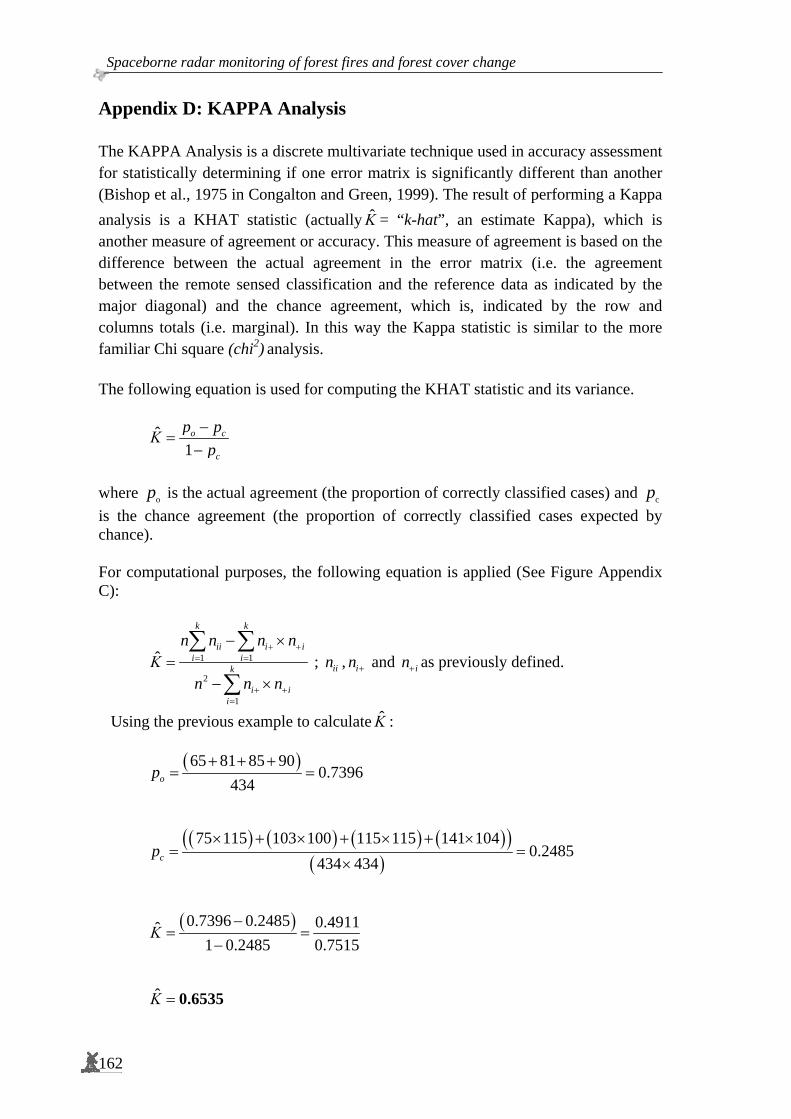
Spaceborne radar monitoring of forest fires and forest cover change
162
Appendix D : KAPPA Analysis The KAPPA Analysis is a discrete multivariate technique used in accuracy assessment for statistically determining if one error matrix is significantly different than another (Bishop et al., 1975 in Congalton and Green, 1999). The result of performing a Kappa analysis is a KHAT statistic (actually Κ̂ = “k-hat”, an estimate Kappa), which is another measure of agreement or accuracy. This measure of agreement is based on the difference between the actual agreement in the error matrix (i.e. the agreement between the remote sensed classification and the reference data as indicated by the major diagonal) and the chance agreement, which is, indicated by the row and columns totals (i.e. marginal). In this way the Kappa statistic is similar to the more familiar Chi square (chi2) analysis. The following equation is used for computing the KHAT statistic and its variance.
ˆ
1o c
c
p pΚp
−=
−
where op is the actual agreement (the proportion of correctly classified cases) and cp is the chance agreement (the proportion of correctly classified cases expected by chance). For computational purposes, the following equation is applied (See Figure Appendix C):
1 1
2
1
ˆ
k k
ii i ii i
k
i ii
n n n nΚ
n n n
+ += =
+ +=
− ×=
− ×
∑ ∑
∑ ; iin , in + and in+ as previously defined.
Using the previous example to calculate Κ̂ :
( )65 81 85 900.7396
434op+ + +
= =
( ) ( ) ( ) ( )( )
( )75 115 103 100 115 115 141 104
0.2485434 434cp
× + × + × + ×= =
×
( )0.7396 0.2485 0.4911ˆ1 0.2485 0.7515
Κ−
= =−
Κ̂ = 0.6535
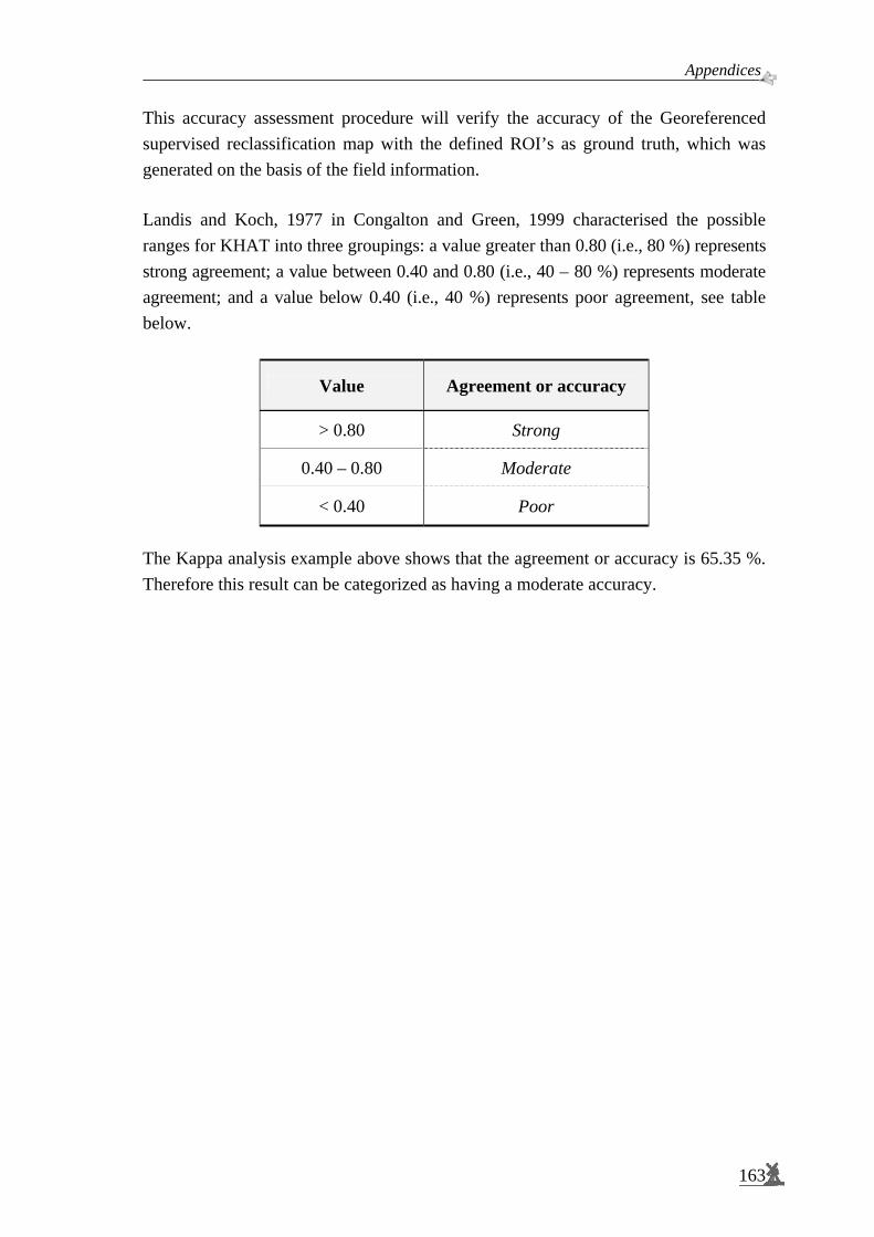
Appendices.
163
This accuracy assessment procedure will verify the accuracy of the Georeferenced supervised reclassification map with the defined ROI’s as ground truth, which was generated on the basis of the field information. Landis and Koch, 1977 in Congalton and Green, 1999 characterised the possible ranges for KHAT into three groupings: a value greater than 0.80 (i.e., 80 %) represents strong agreement; a value between 0.40 and 0.80 (i.e., 40 – 80 %) represents moderate agreement; and a value below 0.40 (i.e., 40 %) represents poor agreement, see table below.
Value Agreement or accuracy
> 0.80 Strong
0.40 – 0.80 Moderate
< 0.40 Poor
The Kappa analysis example above shows that the agreement or accuracy is 65.35 %. Therefore this result can be categorized as having a moderate accuracy.

Spaceborne radar monitoring of forest fires and forest cover change
164
Appendix E : Textural analysis using Grey Level Co-Occurrence technique As has been introduced by Van der Sanden (1997), textural analysis in this study is based on a statistical technique that is known as the grey level co-occurrence technique. The grey level co-occurrence technique is based on the spatial distribution and the mutual spatial dependence of the grey levels in an image. Texture is quantified in terms of statistical parameters that are computed from the elements of a grey level co-occurrence (GLCO) matrix (See also Section 2.8). The textural attributes are listed in Table Appendix E and are described as follows (Van der Sanden, 1997): GLCO-ASM (Angular Second Moment) Measures textural uniformity; high values occur when few p(i,j) are large (close to 1) and others are small (close to 0). This is the case when the area of interest is either homogeneous or texturally uniform, i.e. when the grey level distribution is constant. GLCO-CONT (Contrast) Measures textural contrast, i.e. the presence of sharp grey level transitions (edges). Low values occur when edges are absent. In this case the matrix entries are concentrated around the principal diagonal. GLCO-COR (Correlation) Measures linear-dependencies between the grey levels of pixels pairs. High values (close to 1) imply a strong relationship between pixel pair grey levels. GLCO-COR is uncorrelated to GLCO-ASM as high GLCO-COR values can be measured either in low or high GLCO-ASM situations. GLCO-ENT (Entropy) Measures the disorder in an image, high values occur when many p(i,j) have very small values. The parameter reaches its maximum when the pixels in the area of interest have completely random grey levels. GLCO-ENT is likely to be highly negatively correlated to GLCO-ASM. GLCO-ENT and GLCO-COR are uncorrelated. GLCO-IDM (Inverse Difference Moment) Measures image homogeneity as it assumes larger values when pixel pairs have smaller grey level differences. The parameter is highly negatively correlated to GLCO-CONT. When compared to GLCO-ASM the parameter is less sensitive to the differences in the grey levels of pixel pairs. GLCO-MAX PROB (Maximum Probability) Measures textural uniformity; high values occur when the area of interest is either homogeneous or texturally uniform, i.e. when the grey level distribution is constant. The parameter is positively correlated to GLCO-ASM and negatively correlated to GLCO-ENT.

Appendices.
165
Each textural measure or attribute can be used to create a new textural band that could be used as an input channel for the classification.
Table Appendix E. Textural attribute that were computed from the GLCO matrix. ( )p i, j is a probability value of the GLCO matrix. gN represents the number of
image grey levels and xm , ym , xs and ys represent, respectively the mean values and standard deviations of the row and column position of the counts in the GLCO matrix.
1. Angular Second Moment: (GLCO-ASM)
( )2
1 1,
g g
i j
N Np i j
= =∑ ∑
2. Contrast: (GLCO-CONT)
( )( )2
1 1,
g g
i j
N Np i j i j
= =
−∑ ∑
3. Correlation: (GLCO-COR)
( )( )( )
1 1,
g gx y
i j x y
N N i m j mp i j
s s= =
− −∑ ∑
4. Entropy: (GLCO-ENT)
( ) ( )( )e1 1
, log ,g g
i j
N Np i j p i j
= =
−∑ ∑
5. Inverse Difference Moment: (GLCO-IDM)
( )( )2
1 1
1,1
g g
i j
N Np i j
i j= = + −∑ ∑ with i ≠ j
6. Maximum Probability: (GLCO-MAX PROB)
( ),
max ,i j
p i j
In this study, two GLCO matrices were applied, namely Grey Level Co-Occurrence Contrast (GLCO-CONT) and Grey Level Co-Occurrence Correlation (GLCO-COR) as recommended by Van der Sanden, 1997:
The first textural feature is GLCO-Contrast, with window size 11 x 11 and displacement length 5.
The second textural feature is GLCO-Correlation, with window size 11 x 11 and displacement length 1.

Spaceborne radar monitoring of forest fires and forest cover change
166
Appendix F : Landsat data Landsat is the most popular passive remote sensing satellite. Although it is affected by cloud cover and smoke. Landsat has been widely used in various applications of natural resources observation (i.e. forestry, agriculture, geology). The table below shows characteristics of the Landsat.
Table Appendix F. Characteristics of Landsat
Spatial Resolution
Spectral Resolution Band Electromagnetic
Spectrum TM ETM+ TM ETM+ 1 Visible BLUE-GREEN 30 m 30 m 0.45 – 0.52 µm 0.45 – 0.52 µm2 Visible GREEN 30 m 30 m 0.52 – 0.60 µm 0.53 – 0.61 µm3 Visible RED 30 m 30 m 0.63 – 0.69 µm 0.63 – 0.69 µm4 Near Infrared 30 m 30 m 0.76 – 0.90 µm 0.78 – 0.90 µm5 Mid-Infrared 30 m 30 m 1.55 – 1.75 µm 1.55 – 1.75 µm6 Thermal Infrared 120 m 60 m 10.40 –12.50 µm 10.40 –12.50 µm7 Mid-Infrared 30 m 30 m 2.08 – 2.35 µm 2.09 – 2.35 µm
PAN*) Visible light 15 m 0.52 – 0.90 µmTemporal Resolution Swath Width
16-day sun-synchronous orbits 185 km wide, but it is distributed
in roughly square footprints of 183 km x 170 km
*) Panchromatic
The table shows that a multi-band combination can be generated. The combination result into different types of colour. For example, the 4-3-2 (RGB, Red-Green-Blue) combination gives the same colour performance as the infra red film. It is known as the False Colour Composite, which is advantageous for those who are familiar with this colour. It distinguishes the conifer from deciduous, road, clear cut and water bodies. Another combination, namely 5-4-2 (RGB) gives the best result. It presents an approximate ‘natural colour’, meaning that vegetation is presented as green to yellowish colour, red to orange for soil, and blue to black for water. This combination often well-known as a Pseudo Natural Colour Composite, which is relatively easy to recognise even for people with minimum knowledge in remote sensing (Sugardiman, 1995).
Figure Appendix F-1. Comparison of the Colour Composites (432 vs. 542)
432 (RGB) 542 (RGB)

Appendices.
167
As the Landsat 5-4-2 (RGB) is being enhanced, the distinction between forest conditions become obvious for the naked eye. Those conditions include, for example well-stocked forests compared to degraded forest. This is one positive implication for the planners and decision makers in order to detect/delineate and also to calculate/measure that particular land cover being observed. This band combination therefore, is also called the User-friendly Colour Composite (Sugardiman, 1995). In this study, this composite is used as additional data source which assisted the author during the ground truth data collection. The figure below shows this Landsat TM 5-4-2 (RGB) of the Gunung Meratus test site area.
Figure Appendix F-2. Landsat TM 5-4-2 (RGB) User-friendly Colour Composite, Path/Row: 117/61, dated 16 December 1997.
The most laborious task in radar multi-temporal classification is the selection of the ROI’s. Especially when there are no drastic changes, multi-temporal radar composite has a ‘sandy’ or grainy appearance, making the selection of ROI’s more difficult. The delineation between forest and non forest can be enhanced by applying the vegetation index from Landsat data. In this case, the NDVI (Normalized Difference Vegetation Index) is considered as it is the most widely used index. The NDVI, like most other vegetation indices, is calculated. The two spectral bands are chosen because they are the ones most affected by the absorption of chlorophyll in leafs of green vegetation and the density at the surface. The bands can provide an indication of vigour of the vegetation. Also, within red and near infra-red bands, the contrast between vegetation and soil is at maximum which will make delineation easier.
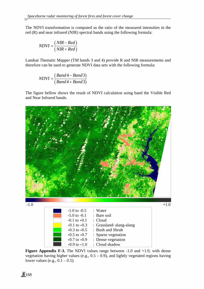
Spaceborne radar monitoring of forest fires and forest cover change
168
The NDVI transformation is computed as the ratio of the measured intensities in the red (R) and near infrared (NIR) spectral bands using the following formula:
( )( )NIR Red
NDVINIR Red
−=
+
Landsat Thematic Mapper (TM bands 3 and 4) provide R and NIR measurements and therefore can be used to generate NDVI data sets with the following formula:
( )( )
4 34 3
Band BandNDVI
Band Band−
=+
The figure bellow shows the result of NDVI calculation using band the Visible Red and Near Infrared bands.
-1.0 +1.0
Figure Appendix F-3. The NDVI values range between -1.0 and +1.0, with dense vegetation having higher values (e.g., 0.5 – 0.9), and lightly vegetated regions having lower values (e.g., 0.1 – 0.5).
-1.0 to -0.5 : Water -5.0 to -0.1 : Bare soil -0.1 to +0.1 : Cloud +0.1 to +0.3 : Grassland/ alang-alang+0.3 to +0.5 : Bush and Shrub +0.5 to +0.7 : Sparse vegetation +0.7 to +0.9 : Dense vegetation +0.9 to +1.0 : Cloud shadow

Appendices.
169

Spaceborne radar monitoring of forest fires and forest cover change
170
Appendix G : Field data Table Appendix G-1. Field check data collection on April 1999 in the small test site (Sungai Wain test site area)
No Lat Long Altitude Remarks 1 -1.02538 116.86481 61.48 Open area (bare soil) 2 -1.02936 116.86780 88.28 Medium Dense Forest 3 -1.02875 116.86504 181.39 Medium Dense Forest 4 -1.02593 116.86694 20.23 Open area (in border of forest) 5 -1.02367 116.86990 133.57 In border of burnt forest 6 -1.02375 116.87102 84.40 Open area (in border of forest) 7 -1.02305 116.87100 118.65 Inside of burnt forest 8 -1.02191 116.86879 79.64 In border of burnt rubber plantation 9 -1.01982 116.86577 39.19 In the main road rubber plantation 2&6 years old
10 -1.01941 116.86584 143.52 In border of burnt rubber plantation 11 -1.01696 116.86253 222.61 Road junctions rubber plantation, small forest 12 -1.01417 116.86222 84.64 In border of burnt rubber plantation 13 -1.01427 116.85507 150.36 Heavy burnt in logged forest 14 -1.01333 116.84733 218.16 Heavy burnt in logged forest 15 -1.01631 116.83626 12.18 Heavy burnt in logged forest 16 -1.02152 116.82432 8.50 Road junctions (Dipterocarp plantation. LOA) 17 -1.02450 116.82121 196.21 In Dipterocarp plantation area (forest-burnt) 18 -1.03137 116.81565 64.21 Enrichment planting 19 -1.04190 116.81097 35.54 Heavy burnt in logged forest 20 -1.05010 116.80120 58.32 Road (in border of burnt area) 21 -1.04844 116.78989 58.65 Road (near an open area and small lake) 22 -1.04300 116.78293 70.93 Burnt logged over forest (with Dipterocarp
Plantation) 23 -1.04773 116.77643 70.93 Burnt logged over forest (with Dipterocarp
Plantation) 24 -1.07405 116.74459 46.05 Log pond (open area, mangrove, unburned) 25 -1.07258 116.75276 134.84 In border of mangrove, slightly burnt 26 -1.01557 116.85172 178.44 Road junction (rubber burnt, Dipterocarp plant
burnt) 27 -1.01084 116.86912 178.44 Logged over forest-burnt, rubber-burnt 28 -0.99161 116.88074 244.13 Fire tower (open area, burnt) 29 -1.00035 116.87055 85.71 Logged over forest-burnt, rubber-burnt 30 -1.01183 116.86738 120.51 Road junction (rubber plantation burnt) 31 -1.02092 116.84330 123.05 Rubber burnt, logger over forest burnt 32 -1.02395 116.85018 223.49 Fire tower (rubber plantation-burnt) 33 -1.03619 116.84032 120.11 Rubber plantation burnt, forest burnt 34 -1.04609 116.83930 142.74 In border of Sungai Wain (SW) conservation area 35 -1.04794 116.84260 101.5 Border of SW conservation area, burnt forest 36 -1.04950 116.84638 54.54 Border of SW conservation area, burnt forest 37 -1.04755 116.84545 37.03 Road junction (rubber burnt, forest burnt) 38 -1.04655 116.84663 188.05 Rubber plantation heavily burnt 39 -1.04573 116.84992 13.78 Rubber plantation burnt 40 -1.00505 116.87360 95.68 Road (border of burnt and unburned LOA)

Appendices.
171
41 -0.99015 116.88669 132.97 Asphalt road curve (ladang, rubber plant Inhutani gate)
42 -0.96462 116.89584 28.20 Asphalt road (ladang, Non Dipterocarp plantation burnt)
43 -0.90712 116.77623 22.20 Rice fields in Sepaku II 44 -0.91366 116.82060 22.20 Traffic light in Sepaku III (open area, road) 45 -0.96140 116.80553 109.21 Waterfront in Semoi IV (mangrove, Nipah) 46 -0.95775 116.82069 11.78 Ladang, alang-alang grassland in Semoi IV 47 -0.92858 116.89958 22.26 Alang-alang grassland, ladang with trunks
previously burnt 48 -1.01206 116.87214 75.89 Road junction (open area) burnt, plantation, Bukit
Bangkirai 49 -1.00965 116.89169 27.68 LOA with enrichment plant, plant, Bukit Bangkirai50 -1.01145 116.90309 49.97 LOA, heavily burnt forests with high tree,
enrichment plant. 51 -1.01199 116.90815 42.81 Forest heavily burnt forest with high tree 52 -1.01702 116.90948 42.81 Forest heavily burnt forest with high tree, nothing
left. 53 -1.02606 116.90730 104.08 Plantation camp (open area) LOA, burnt, land-
clearing 54 -1.05313 116.90218 96.81 Rubber plantation, with shrub and bush 55 -1.06213 116.89932 63.02 Road junction rubber plantation, S. Wain border 56 -1.09037 116.90521 174.91 Inhutani gate km 24 S. Wain & ladang 57 -1.02442 116.86927 174.91 Track/path junction in Bukit Bangkirai burnt and
unburned 58 -1.02557 116.87017 174.91 Track unburned 59 -1.02582 116.87097 174.91 Firebreak burnt and unburned 60 -1.23005 116.80991 5.77 PT ITCI harbour 61 -0.99533 116.78020 57.56 In the river to the land are mangrove, grassland, 62 -0.98868 116.78206 1.16 In the river to the land are mangrove, lowland
forest 63 -0.95572 116.80334 39.67 In the river to the land is Nipah 64 -0.94458 116.80482 30.99 In the river to the land are log-pond (open area),
plantation 65 -0.95473 116.79164 308.13 In the river to the land is mangrove 66 -1.02541 116.87137 138.65 Firebreak burnt and unburned 67 -1.02681 116.87160 110.05 Track burnt and unburned there is small river 68 -1.02690 116.87226 123.14 Road burnt (200 m) then unburned 69 -1.02804 116.87327 56.82 Road burnt (200 m) then unburned small river 70 -1.03106 116.87816 56.82 Road burnt & unburned small river 71 -1.03285 116.87396 56.82 Unburned forest (maybe highest point of Bukit
Bangkirai) 72 -1.03281 116.87136 164.13 Secondary firebreak unburned 73 -1.03375 116.86750 118.99 Track unburned 74 -1.03477 116.86452 41.56 Road burnt and unburned forest area 75 -1.03381 116.86282 19.15 Road burnt & unburned rubber plantation 76 -1.03162 116.86116 39.56 Road burnt (200 m) then unburned, rubber
plantation 77 -1.02992 116.86126 5.08 In Bukit Bangkirai burnt & unburned 78 -1.03003 116.86153 32.32 In Bukit Bangkirai burnt & unburned

Spaceborne radar monitoring of forest fires and forest cover change
172
Table Appendix G-2. Field data collection in September 2000 during the PacRim-II campaign (Sungai Wain, Panajam and Sesulu area)
No Lat Lon Alt Remarks 1 -1.42070 116.60030 22.00 Tidal flat 100 m, High tide in the night 2 -1.41790 116.59900 27.00 Strip extend from 280 to 70, Width < 100 m 3 -1.41680 116.59810 25.00 Perimeter is a track, Tree height +/- 80 Cm 4 -1.41400 116.59840 24.00 Direction 60 > 2 Km 5 -1.41220 116.59720 17.00 T. Junction to Salloloang 6 -1.38170 116.70790 19.00 Salloloang Oil Pump 7 -1.37920 116.70540 19.00 Tree Height 8 -1.37210 116.69840 23.00 Grass, grass, Palm/Coconut 9 -1.37340 116.69600 25.00 Plant Height 60 cm, Age 3 month, +/- Flooded 10 -1.36650 116.69280 23.00 Height of shrub, Swamp 11 -1.35590 116.58800 34.00 With > 200 x 300, Less air (more vegetation) 12 -1.36450 116.60100 21.00 Ex garden 13 -1.36710 116.60340 31.00 Open area 14 -1.36760 116.60310 46.00 Banana garden 15 -1.37620 116.61020 51.00 Alang-alang along the road 16 -1.39580 116.61850 22.00 Up 3 m height, Alang-alang 17 -1.39860 116.62020 21.00 Rice field 18 -1.40660 116.62650 22.00 Open area (bare soil) 19 -1.40790 116.62700 15.00 Open area (Shrimp pond) 20 -1.40460 116.62530 15.00 Mixed mangrove (small vegetation) 21 -1.28750 116.66230 89.00 Boundary rubber plantation 22 -1.38720 116.61450 30.00 Secondary forest 23 -1.29400 116.66140 83.00 Palm oil plantation 24 -1.33230 116.66980 54.00 Man made (oil factory) 25 -1.33230 116.66980 54.00 Wasted area 26 -1.38010 116.57350 17.00 Boundary from home garden, large area >30 Km 27 -1.39090 116.57660 38.00 Buffer +/- 200m mix kebun, Alang-alang > 200 m 28 -1.39440 116.59040 23.00 Swamp in low area and dry land next door 29 -1.39610 116.59160 25.00 Palm oil, burnt area +/- 100 m from road 30 -1.38560 116.62790 15.00 Large area beside main road 31 -1.36450 116.65510 23.00 See sketch 32 -1.17420 116.83350 38.00 Along the river 33 -1.17420 116.83350 15.00 Big Mangrove 34 -1.19470 116.81370 12.00 >100 m is alang2 in north direction 35 -1.18350 116.82670 13.00 Mangrove 36 -1.18960 116.80690 20.00 Shrimp ponds 37 -1.18090 116.80610 7.00 Big Mangrove 38 -1.20420 116.78250 36.00 Alang-alang 39 -1.16580 116.78000 12.00 Alang-alang 40 -1.12870 116.76790 12.00 Alang-alang/ Mangrove 41 -1.12410 116.77990 13.00 Mangrove Secondary 42 -1.08460 116.90600 76.00 Power Line 44 - 236 direction, Garden, Waste land43 -1.08070 116.90700 74.00 Garden, Waste Land, Open area 44 -1.07120 116.90530 81.00 Burnt Area, Alang-alang
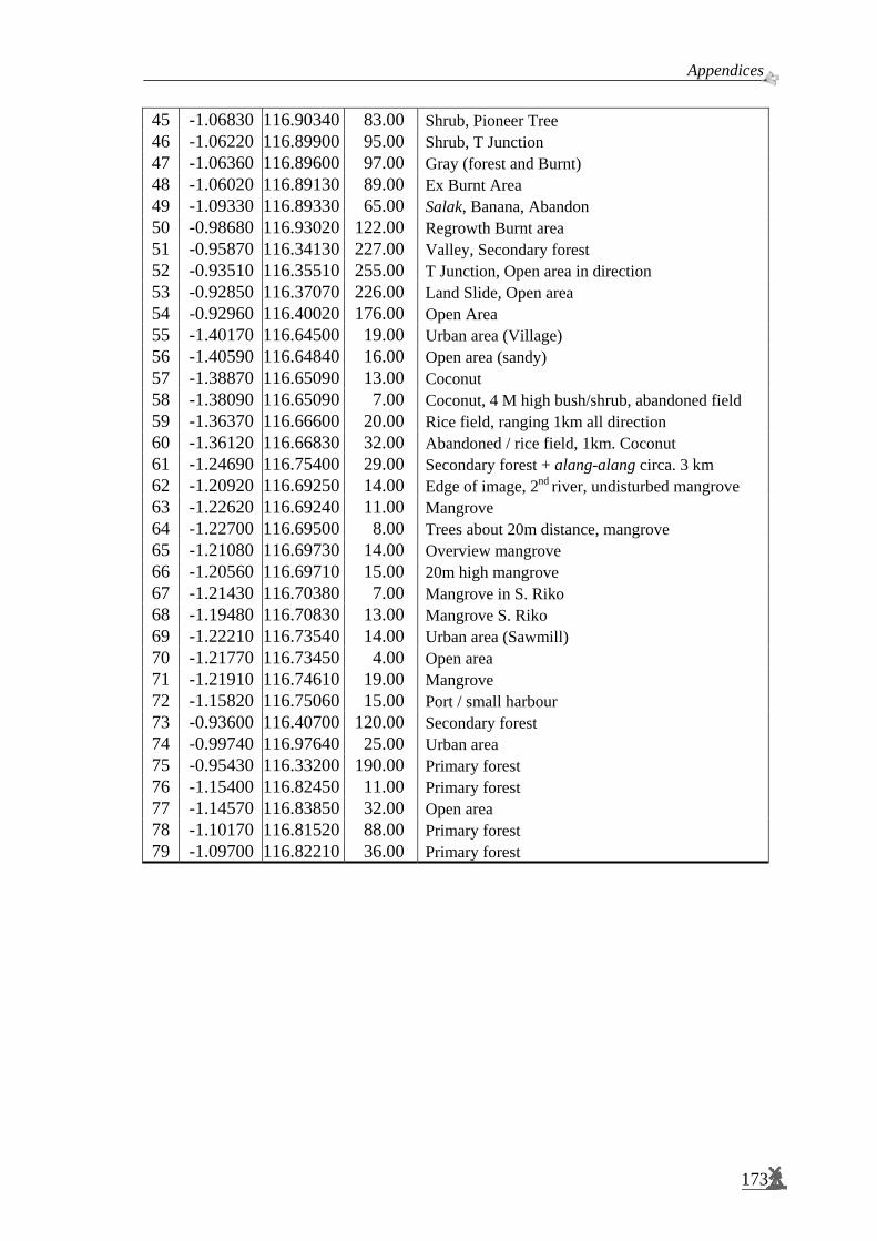
Appendices.
173
45 -1.06830 116.90340 83.00 Shrub, Pioneer Tree 46 -1.06220 116.89900 95.00 Shrub, T Junction 47 -1.06360 116.89600 97.00 Gray (forest and Burnt) 48 -1.06020 116.89130 89.00 Ex Burnt Area 49 -1.09330 116.89330 65.00 Salak, Banana, Abandon 50 -0.98680 116.93020 122.00 Regrowth Burnt area 51 -0.95870 116.34130 227.00 Valley, Secondary forest 52 -0.93510 116.35510 255.00 T Junction, Open area in direction 53 -0.92850 116.37070 226.00 Land Slide, Open area 54 -0.92960 116.40020 176.00 Open Area 55 -1.40170 116.64500 19.00 Urban area (Village) 56 -1.40590 116.64840 16.00 Open area (sandy) 57 -1.38870 116.65090 13.00 Coconut 58 -1.38090 116.65090 7.00 Coconut, 4 M high bush/shrub, abandoned field 59 -1.36370 116.66600 20.00 Rice field, ranging 1km all direction 60 -1.36120 116.66830 32.00 Abandoned / rice field, 1km. Coconut 61 -1.24690 116.75400 29.00 Secondary forest + alang-alang circa. 3 km 62 -1.20920 116.69250 14.00 Edge of image, 2nd river, undisturbed mangrove 63 -1.22620 116.69240 11.00 Mangrove 64 -1.22700 116.69500 8.00 Trees about 20m distance, mangrove 65 -1.21080 116.69730 14.00 Overview mangrove 66 -1.20560 116.69710 15.00 20m high mangrove 67 -1.21430 116.70380 7.00 Mangrove in S. Riko 68 -1.19480 116.70830 13.00 Mangrove S. Riko 69 -1.22210 116.73540 14.00 Urban area (Sawmill) 70 -1.21770 116.73450 4.00 Open area 71 -1.21910 116.74610 19.00 Mangrove 72 -1.15820 116.75060 15.00 Port / small harbour 73 -0.93600 116.40700 120.00 Secondary forest 74 -0.99740 116.97640 25.00 Urban area 75 -0.95430 116.33200 190.00 Primary forest 76 -1.15400 116.82450 11.00 Primary forest 77 -1.14570 116.83850 32.00 Open area 78 -1.10170 116.81520 88.00 Primary forest 79 -1.09700 116.82210 36.00 Primary forest
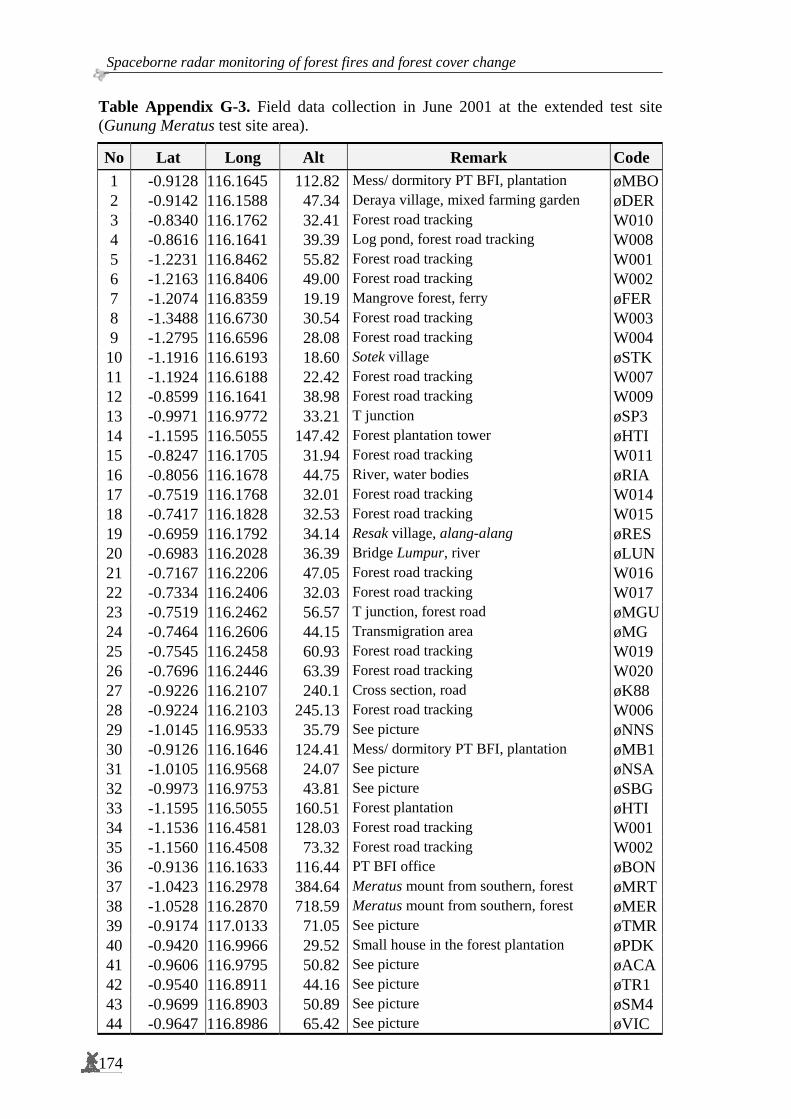
Spaceborne radar monitoring of forest fires and forest cover change
174
Table Appendix G-3. Field data collection in June 2001 at the extended test site (Gunung Meratus test site area).
No Lat Long Alt Remark Code 1 -0.9128 116.1645 112.82 Mess/ dormitory PT BFI, plantation øMBO2 -0.9142 116.1588 47.34 Deraya village, mixed farming garden øDER3 -0.8340 116.1762 32.41 Forest road tracking W010 4 -0.8616 116.1641 39.39 Log pond, forest road tracking W008 5 -1.2231 116.8462 55.82 Forest road tracking W001 6 -1.2163 116.8406 49.00 Forest road tracking W002 7 -1.2074 116.8359 19.19 Mangrove forest, ferry øFER 8 -1.3488 116.6730 30.54 Forest road tracking W003 9 -1.2795 116.6596 28.08 Forest road tracking W004
10 -1.1916 116.6193 18.60 Sotek village øSTK 11 -1.1924 116.6188 22.42 Forest road tracking W007 12 -0.8599 116.1641 38.98 Forest road tracking W009 13 -0.9971 116.9772 33.21 T junction øSP3 14 -1.1595 116.5055 147.42 Forest plantation tower øHTI 15 -0.8247 116.1705 31.94 Forest road tracking W011 16 -0.8056 116.1678 44.75 River, water bodies øRIA 17 -0.7519 116.1768 32.01 Forest road tracking W014 18 -0.7417 116.1828 32.53 Forest road tracking W015 19 -0.6959 116.1792 34.14 Resak village, alang-alang øRES 20 -0.6983 116.2028 36.39 Bridge Lumpur, river øLUN21 -0.7167 116.2206 47.05 Forest road tracking W016 22 -0.7334 116.2406 32.03 Forest road tracking W017 23 -0.7519 116.2462 56.57 T junction, forest road øMGU24 -0.7464 116.2606 44.15 Transmigration area øMG 25 -0.7545 116.2458 60.93 Forest road tracking W019 26 -0.7696 116.2446 63.39 Forest road tracking W020 27 -0.9226 116.2107 240.1 Cross section, road øK88 28 -0.9224 116.2103 245.13 Forest road tracking W006 29 -1.0145 116.9533 35.79 See picture øNNS30 -0.9126 116.1646 124.41 Mess/ dormitory PT BFI, plantation øMB131 -1.0105 116.9568 24.07 See picture øNSA32 -0.9973 116.9753 43.81 See picture øSBG 33 -1.1595 116.5055 160.51 Forest plantation øHTI 34 -1.1536 116.4581 128.03 Forest road tracking W001 35 -1.1560 116.4508 73.32 Forest road tracking W002 36 -0.9136 116.1633 116.44 PT BFI office øBON37 -1.0423 116.2978 384.64 Meratus mount from southern, forest øMRT38 -1.0528 116.2870 718.59 Meratus mount from southern, forest øMER39 -0.9174 117.0133 71.05 See picture øTMR40 -0.9420 116.9966 29.52 Small house in the forest plantation øPDK41 -0.9606 116.9795 50.82 See picture øACA42 -0.9540 116.8911 44.16 See picture øTR1 43 -0.9699 116.8903 50.89 See picture øSM4 44 -0.9647 116.8986 65.42 See picture øVIC

Appendices.
175
Table Appendix G-4. Field data collection in November 2004 during the INDREX-2 campaign (Sungai Wain, Samboja Lestari test site area).
No Lat Long Date Name 1 -1.04778 116.97772 15/11/2004 Samboja Lestari Acacia 2 -1.04559 116.97950 15/11/2004 Samboja Lestari Gmelina 3 -1.04767 116.97906 16/11/2004 Samboja Lestari Teak 4 -1.05273 116.99442 16/11/2004 Samboja Lestari Agroforestry 5 -1.29625 116.66961 17/11/2004 Oil palm 3-5 years 6 -1.28647 116.67800 17/11/2004 Rubber tree plantation 7 -1.22298 116.73044 17/11/2004 Mangrove river around this coordinates 8 -1.18017 116.75902 17/11/2004 Mangrove 9 -1.11555 116.82664 19/11/2004 Sungai Wain A0 10 -1.11317 116.82570 20/11/2004 Sungai Wain E10 11 -1.12177 116.82971 20/11/2004 Fallen Tree 12 -1.12595 116.83079 20/11/2004 Allelo 13 -1.29806 116.66699 23/11/2004 Cross section 14 -1.27312 116.71699 23/11/2004 Houses in rubber plantation 15 -1.27597 116.69755 24/11/2004 Rubber 8 years 16 -1.27658 116.69886 24/11/2004 Rubber 12 years 17 -1.05941 116.97610 26/11/2004 My tree 18 -1.05659 116.98031 26/11/2004 Office 19 -1.03611 116.98435 26/11/2004 Big tree 20 -1.02986 116.99368 26/11/2004 Black1 21 -1.04960 116.98378 27/11/2004 Teak second plot 22 -1.04331 116.99347 27/11/2004 Samboja Lestari secondary forest 23 -1.04412 116.99389 27/11/2004 Alang-alang
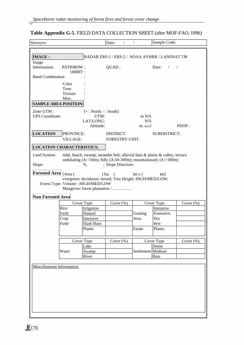
Spaceborne radar monitoring of forest fires and forest cover change
176
Table Appendix G-5. FIELD DATA COLLECTION SHEET (after MOF-FAO, 1996) Surveyor: Date: / / Sample Code:
IMAGE : RADAR ERS-1 / ERS-2 / NOAA AVHRR / LANDSAT TM
Image Information: PATH/ROW : QUAD : Date: / /
ORBIT : Band Combination :
Color : Tone : Texture : Misc. :
SAMPLE AREA POSITION:
Zone UTM : [+ : North; - : South] GPS Coordinate: UTM: m N/S LAT/LONG: N/S Altitude: m. a.s.l PDOP :
LOCATION PROVINCE: DISTRICT: SUBDISTRICT: VILLAGE: FORESTRY UNIT:
LOCATION CHARACTERISTICS:
Land System: tidal, beach, swamp, meander belt, alluvial fans & plains & valley, terrace undulating (A:<50m); hilly (A:50-300m); mountainously (A:>300m) Slope: % ; Slope Direction:
Forested Area [Area ( ) ha; ( )m x ( )m]
Forest Type: evergreen/ deciduous/ mixed; Tree Height: HIGH/MED/LOW; Volume : HIGH/MED/LOW
Mangrove/ forest plantation /……………
Non Forested Area Cover Type Cover (%) Cover Type Cover (%) Rice Irrigation Intensive Field Natural Grazing Extensive: Crop Intensive Area Dry Field Slash Burn Wet Plants: Estate Plants:
Cover Type Cover (%) Cover Type Cover (%) Lake Dense Water Swamp Settlement Medium River Rare Miscellaneous Information:

Appendices.
177
Forest Fire Fire Type: a. Crown Fire c. Ground Fire b. Surface Fire d. Fire combination
Fire Intensity: hours/days/months
Damage Rate: a. Low c. High b. Medium d. Very High
Succession: Miscellaneous Information: Location map or Sketch: Multi-temporal Color Composite (RGB) (Scale 1: ) (Scale 1: ) Photographic of Location: (Film No: ; Roll: )

Spaceborne radar monitoring of forest fires and forest cover change
178
Appendix H : Future Synthetic Aperture Radar sensor
ALOS-PALSAR The Advanced Land Observing Satellite (ALOS or Daichi) has been developed to contribute to the fields of mapping, precise regional land coverage observation, disaster monitoring, and resource surveying. It was launched by the H-IIA launch vehicle No.8 from the Tanegashima Space Centre in January 24, 2006 into a Sun-Synchronous Sub-Recurrent orbit at an altitude of 691.65 km at a 98.16° inclination angle. Along with the start of the regular operations, JAXA also started providing observation data (called "ALOS data") to the public on October 24, 2006. ALOS was designed for 3 to 5 years operation, with a repeat-cycle of 46 days. The ALOS satellite has three sensors: (a) Phased Array type L-band Synthetic Aperture Radar (PALSAR), which enables day-and-night and all-weather land observation, (b) the Panchromatic Remote-sensing Instrument for Stereo Mapping (PRISM), which is comprised of three sets of optical systems to measure precise land elevation; and (c) the Advanced Visible and Near Infrared Radiometer type 2 (AVNIR-2), which observes what covers land surfaces.
Figure Appendix H-1. A. ALOS satellite with three sensors: PALSAR, PRISM, and AVNR-2. B. PALSAR sensor (antennae). The Phased Array type L-band Synthetic Aperture Radar (PALSAR) is an active microwave sensor using L-band frequency to achieve cloud-free and day-and-night land observation. It provides higher performance than the JERS-1's synthetic aperture radar (SAR). Fine resolution in a conventional mode, but PALSAR will have another advantageous observation mode. ScanSAR, which will enable us to acquire a 250 to 350 km width swath of SAR images (depending on the number of scans) at the expense of spatial resolution (Further information in EORC, JAXA, 1997). This swath is three to five times wider than conventional SAR images, and comparable to the ENVISAT ASAR Wide Swath. The development of the PALSAR is a joint project between JAXA and the Japan Resources Observation System Organization (JAROS). Detailed characteristics of PALSAR are shown in Table Appendix H-1.
A B

Appendices.
179
Table Appendix H-1. ALOS-PALSAR characteristics
PALSAR characteristics
Mode Fine ScanSAR Polarimetric
Centre Frequency 1,270 MHz (L-band)
Chirp Bandwidth 28 MHz 14 MHz 14 MHz, 28 MHz 14 MHz
Polarization HH or
VV
HH+HV or
VV+VH
HH or
VV HH+HV+VH+VV
Incidence angle 8 – 60 ° 8 – 60 ° 18 – 43 ° 8 – 30 °
Range Resolution 7 – 44 m 14 – 88 m 100 m (multi look) 24 – 89 m
Observation Swath 40 – 70 km 40 – 70 km 250 – 350 km 20 – 65 km
TerraSAR-X
TerraSAR-X (also referred to as TSX-1) is the first German satellite to be built in a Public Private Partnership (PPP) between DLR and EADS Astrium. (Further information in Kramer, 2002; EADS, 2007 and SEOR, 2007).
TerraSAR-X is a new generation, high resolution satellite operating in the X-band at 9.65 GHz. It will be launched from Baikonur on 27 February 2007 into Sun-synchronous orbit at an altitude of 514 km with inclination 97.44°. TerraSAR-X is to be operated for a period of at least 5 years with a revisit time (orbit repeat cycle) of 11 days. The TerraSAR-X characteristics are listed in Table Appendix H-3 below.
Table Appendix H-3. TerraSAR-X characteristics
TerraSAR-X characteristics Mode SpotLight StripMap ScanSAR Launch date Expected on 27 February 2007 Radar carrier frequency 9.65 GHz (X-band; 3.1 cm wavelength) Polarization: HH, VV, HV, VH Single, Dual Single, Dual, Quad Single
Resolution 1 m 3 m 16 m Nominal Scene Size 10 km x 5 km 30 km x 50 km 100 km x 150 km
Max Strip Length - 4,200 km 4,200 km Incidence angle - full performance - accessible
20° - 55° 15°- 60°
20° - 45° 15° - 60°
20° - 45° 15° - 60°
SAR antenna: 4.8 m x 0.80 m x 0.15 m Nominal antenna look direction right

Spaceborne radar monitoring of forest fires and forest cover change
180
Figure Appendix H-1. TerraSAR-X satellite and overview of the TerraSAR-X scanning modes
TanDEM-X TanDEM-X (TerraSAR-X add-on for Digital Elevation Measurement) has the goal of generating a global Digital Elevation Model (DEM) with an unprecedented accuracy corresponding to the DTED-310 specifications. This goal will be achieved by means of a second SAR satellite (TanDEM-X) flying in a tandem orbit configuration with TerraSAR-X (TSX-1).
TanDEM-X has SAR system parameters which are fully compatible with TSX-1, allowing not only independent operation from TSX-1 in a mono-static mode, but also synchronized operation (e.g. in a bi-static mode). The TanDEM-X satellite is designed for a nominal lifetime of 5 years and has a nominal overlap with TerraSAR-X (TSX-1) of 3 years. It is proposed to be launched in 2009. A prolongation of the mission overlap is possible by means of an extension of TSX-1 operation, which is compatible with the TSX-1 consumables and resources (Moreira et al., 2004; Infoterra, 2007). The scientific use of the data can be divided into three areas of application: new quality Digital Elevation Models (e.g. for hydrology), along-track interferometry (e.g. measurement of ocean currents) and new bi-static applications (e.g. polarimetric SAR interferometry).
10 Digital Terrain Elevation Data (DTED®) has been developed by the National Imagery
and Mapping Agency (NIMA). It is a standard for a uniform matrix of terrain elevation values which provides basic quantitative data for systems and applications that require terrain elevation, slope, and/or surface roughness information. (Further information in FAS, 2000). Digital Terrain Elevation Data (DTED®):
DTED level Post spacing Ground distance Row x column Tile size 1 3.0 second ~ 100 m 1200 x 1200 1 x 1 degree 2 1.0 second ~ 30 m 3600 x 3600 1 x 1 degree
3* 0.3333 second ~ 10 m 900 x 900 5 x 5 minute 4* 0.1111 second ~ 3 m 540 x 540 1 x 1 minute 5* 0.0370 second ~ 1 m 810 x 810 30 x 30 second
*) Levels 3, 4 and 5 at increasing resolution have been proposed, but not yet standardized.

Appendices.
181
Figure Appendix H-2. The TanDEM-X mission allows for the generation of world-wide, consistent, timely, high-precision Digital Elevation Models. The figure shows there are vertical and horizontal baselines (known as Helix-satellite formation).
The TSX-1 satellite, as a basis for TanDEM-X, is not only a high performance SAR system with respect to SAR image and operational features, but it is already built for repeat-pass interferometry.
Table Appendix H-4. Tandem-X Mission and System Requirements (Moreira et al., 2004)

Spaceborne radar monitoring of forest fires and forest cover change
182
TanDEM-X has two operation modes to perform DEM generation: bistatic InSAR mode and monostatic InSAR mode. In principle, the bistatic InSAR mode is characterized by the simultaneous measurement of the same scene and identical Doppler spectrum with 2 receivers, thereby avoiding temporal decorrelation. To provide sufficient overlap of the Doppler spectra, along-track baselines < 2 km are required while the effective across-track baselines for high resolution DEMs have to be in the order of 1 km. A secondary DEM generation mode is the pursuit monostatic InSAR mode, where two satellites are operated independently, avoiding the need for synchronization. The along-track distance is 30 – 50 km. The temporal decorrelation is still small for most terrain types (See Figure 5-11.).
Figure Appendix H-3. TanDEM-X InSAR observations in bistatic and monostatic modes.
SENTINEL-1 In the frame of the Global Monitoring for Environment and Security Programme (GMES), ESA is undertaking the development of a European Radar Observatory (SENTINEL-1), a European polar orbit satellite system for the continuation of SAR operational applications in C-band after the ASAR-ENVISAT is decommissioned. The SENTINEL-1 series of satellites will address the issue of data continuity for SAR data at large. The immediate priority is to ensure such continuity for C-band data. Under the current scenario, provision of ASAR-ENVISAT data to feed SAR-based services is likely to cease in the 2008 – 2010 timeframe. The design of SENTINEL-1 SAR system has been driven by the need for continuity of ERS/ ENVISAT class data provision with improved revisit, coverage, timeliness and reliability of service, i.e. the experience with ERS and ENVISAT constitutes the basis for the SENTINEL-1 mission requirements and concept (Attema, 2005; Attema et al., 2006; Davidson, 2006). In order to meet the need for continuity, the first SENTINEL-1 satellite should be launched before the end of the ENVISAT operations; it is expected to be launched in 2011, and it will be in a Near-polar Sun-synchronous orbit with a 12-day repeat cycle and 175 orbits per cycle. To satisfy revisit requirements a constellation of satellites is required with 2 satellites as a minimum. With both satellites operating for 20 minutes per orbit. The main technical SENTINEL-1 characteristics are listed in the Table Appendix H-2.
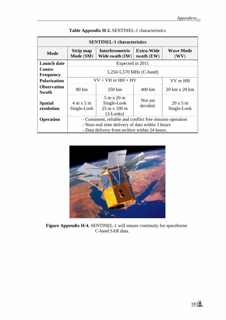
Appendices.
183
Table Appendix H-2. SENTINEL-1 characteristics
SENTINEL-1 characteristics
Mode Strip map Mode (SM)
Interferometric Wide swath (IW)
Extra-Wide swath (EW)
Wave Mode (WV)
Launch date Expected in 2011 Centre Frequency 5,250-5,570 MHz (C-band)
Polarization VV + VH or HH + HV VV or HH Observation Swath 80 km 250 km 400 km 20 km x 20 km
Spatial resolution
4 m x 5 m Single-Look
5 m x 20 m Single-Look
25 m x 100 m (3-Looks)
Not yet decided.
20 x 5 m Single-Look
Operation - Consistent, reliable and conflict free mission operation - Near-real time delivery of data within 3 hours - Data delivery from archive within 24 hours.
Figure Appendix H-4. SENTINEL-1 will ensure continuity for spaceborne C-band SAR data.

Acknowledgements “The word is not enough”. Above all, I would like to express my great thankfulness to ALLAH “GOD” for His kindness, support, mercy and grace that He extended me, Alhamdulillah. I am aware and assured whatever we gain in knowledge, power or success, we could not proceed without help, guidance and support from ALLAH. I would like also to extend my gratitude and thanks to all people whom ALLAH made available to ease my stay and to support and guide my family and I during our stay in The Netherlands. There are many people who have helped me out over the years to complete this dissertation. I have been fortunate enough to have had the support of so many people and without it this would not have been possible. Therefore, I consider my work is incomplete without these acknowledgements. This study was started when Dr. ir. W.T.M. Smits asked me to meet Dr. ir. D.H. Hoekman in Wanariset, Samboja, East Kalimantan during the peak of the fire event, El Niño 1998. That stimulated me to join the project and to contribute with research on the extreme phenomenon of forest fires. Dr. ir. W.T.M. Smits - who has thousands of bright ideas popping-up every second - not only provided me with new insights but also guaranteed financial support during my stay with my family in The Netherlands. I am really impressed by his constant and unending endurance and stamina. Terima kasih, Pak Willie. I would like to express my sincere appreciation to the person most involved with this dissertation; i.e. my daily supervisor and co-promotor Dr. ir. D.H. Hoekman for his excellent guidance and invaluable support. I still recall when he said: ‘I will not leave you alone’ after I had been left in my home country of Indonesia by members of the group known as ‘Hoekman Four’ (Muli, Kemal, Bambang). That was very encouraging to me, Thanks Dirk. Special thanks are extended to my promotor Prof. Dr. ir. R.A. Feddes. His willingness to take care of me in spite of his busy schedule as well as not only coming in to inspect finished products but working through each chapter with me taught me a lot about thinking scientifically. His challenging remark: ‘Ruandha, please don’t bring your ‘nice’ culture here to our discussion’, ‘toughened’ me in terms of finalizing my dissertation. I would like to extend my gratitude to the Indonesian Ministry of Forestry and to the Dutch Government for all their support, which allowed me to pursue my PhD degree at Wageningen University. I would like also to thank the Nuffic Huygens Fellowship Program, Tropenbos International, the Gibbon Foundation (YGI), and the Borneo Orang-utan Survival (BOS) Foundation for their financial backing. I would especially like to thank Their Excellencies from the Minister of Forestry Mr. Djamaludin Suryohadikusumo, Mr. Sumahadi, Mr. Muslimin Nasution, Mr. Nurmahmudi Ismail, Mr. Marzuki Usman, Mr. Prakosa, and Mr. Kaban for their support and encouragement. There are many others in the Ministry of Forestry, who, in one way or another, supported and encouraged me. I thank them all. Special thanks go to the ‘Radar Group’ members - the people from Tropenbos called us the ‘Hoekman Four’ which extended to six with the inclusion of Wisnu and Yayu. Thank you guys for your valuable discussion, useful comments and constructive criticisms and also to their families who always struggled together and shared the experience of being here.
185

Spaceborne radar monitoring of forest fires and forest cover change
186
A very special thanks goes to my late best friend, DR. Ir. H. Muljanto Nugroho, MF who sadly could not see the completion of this work. Our friendship grew to become a brotherhood relationship - our family has become one big family - and of course we were deeply shocked with what happened to him. Bu Oke, Lieke, Ian and Zaki be strong!, Pak Muli insya Allah will reach his dream, Selamat jalan sahabat,. semoga menjumpai mimpimu, To! Your spirits and positive thinking will always sprinkle to our hearts. I would also like to thank all colleagues in Sarvision Nederland and Indonesia, BOS and YGI: Martin, Arjen, Vincent, Niels, Marcela, Anton; Budhi, Kiki, Erwanto, Yati; DR. Aldrianto, Ishak; Dudung and Herly, for their kind support (technical and administrative), valuable discussions and willingness to share their experiences. To all Indonesian students ~ Perhimpunan Pelajar Indonesia – PPI Wageningen, Indonesian families and buloker in Wageningen, I also express my sincere thanks. With you all as friends, Indonesia’s atmosphere and circumstances emerge here in Wageningen - it’s become a remedy for my yearning. They are too many to name it; still the following names deserve to be mentioned as they support me on the stage during my public defence: Mohamad Djaeni and Yurdi Yasmi as my paranymphs. Special appreciation goes to our brothers-friends here in Wageningen: Ahmad Mateen, Abdul Aziz, Hussein, Hassan Sawalha, Rafat, Mustofa, Hamada, Ishahrul, Rahmani, Saleh, Marco Traa (H.Yahya) and their families - we will never forget you all. I always make du’a; soon we will have masjid here. I extend my gratitude to the head and staff members of the Education-Culture, Consular and Immigration Affairs of the Indonesian Embassy in Den Haag for their help and support during my stay in The Netherlands. Terima kasih Pak Muhadjir, Pak Rudhy, Pak Ajiph, Pak Priyono, Pak Wito, Bu Maria, Pak Hasyim, Pak Sulaeman, Pak Djauhari dan Pak J.E. Habibie. Most important of all, I would like to thank my beloved wife, Retno Maryani, for her understanding, patience, full support, concern about my research and continued advice, discussion and assistance. En natuurlijk ook mijn geliefde dochters, Rahardhyani Primarista and Rahardhyani Dwiannisa, who always encourage and accompany me when in need and provided a source of happiness throughout the period of my study, and who are also correcting and criticizing my ‘Hollands spreken’, which has far from improved. You are all my inspirations, schatten! I will never forget also Rista and Annis’s juffrouw en meester in OBS De Nude and RS Pantarijn: Nell, Ineke van Tintelen, Gerlof Gerritsen, late Henk Massier, Anita Smid, Miriam Kleyn, Anne Segeren, Chantal Kronenberg, and Monique Delno; Aafke Piekaar, Astrid Kengen, John Visser, Jack Bogers and Marjon Groenhout. Dank U wel, allemaal! My gratitude to my honourable mother, Rahaju Siti Sumadijani, who always prayed for me, gave me blessings and spiritual support from thousands of kilometres away. Ibu, you are my motivation. To my brother and sisters, Agung, Ita, Ria, and their families: Semoga cita-cita almarhum Bapak, Pak Djon terwujud sudah. Also to Bapak-Ibu Martadji, my parents in-law and ‘the big family’, Mas Heru, Mas Budi, Yoyok, Hari and Hasti thank you for your support and attention while we were abroad. I am certainly indebted to my friends, Retnosari, Mela, Bu Jujuk and family as well as Rahmat Misto who always took care of my ‘things and business’ during my absence. Only ALLAH will repay and reward their good deeds and sincerity which I will always hope and appeal for…
Wageningen, March 2007 Ruandha Agung Sugardiman

Curriculum Vitae Ruandha Agung Sugardiman was born in Madiun-East Java, Indonesia on March 1, 1962. He completed his High School education in his home town and continued with studies in the Faculty of Forestry at Gadjah Mada University, Yogyakarta in 1981. In 1986, he graduated and received the degree of Forest Engineer (Ir.) with a major in forest management specialising in aerial photogrammetry. In 1987, he began work at the Forest Inventory and Mapping Agency within the Banjarbaru Regional Office of the Ministry of Forestry, South Kalimantan, Indonesia. Between 1990 to 1992 he received job training to follow a course in (Advanced) Postgraduate Geoinformation Systems for Rural Application in ITC, Enschede, The Netherlands. Afterwards, he moved from the Regional Office of the Ministry of Forestry to Office Headquarters in Jakarta, working within the Agency for Forest Inventory and Land-use Planning (INTAG), recently known as Forestry Planning Agency (BAPLAN). During this time, he has given many lectures to students, technicians, staffs and trainees concerning remote sensing, global positioning systems and geographic information system. In this fields, he supervised students of Gadjah Mada University Yogyakarta, Bogor Agriculture University and Bandung Institute of Technology with a particular focus on forestry applications. During 1994 to 1996, he was a member of the National Committee of Natural Resources Database Network coordinated by the National Coordinating Agency for Surveys and Mapping (BAKOSURTANAL). He was also a member of the Remote Sensing Counterpart and Extension Core Group Member of the JOFCA-ITTO Project from 1994 to 1999. In 1999, he was admitted to Wageningen University, Wageningen, The Netherlands to continue his academic studies. He was awarded with an MSc. degree in 2000, which focused on Geo-information Systems for Rural Applications. He subsequently proceeded with a PhD programme at Wageningen University, with Prof. dr. ir. R.A. Feddes as promotor and Dr. ir. D.H. Hoekman as co-promotor. His main research interest is in the area of radar remote sensing for tropical forests, with an emphasis on the development of monitoring systems using multi-temporal spaceborne synthetic aperture radar (SAR) data. After completing his PhD in 2007, he will return to Indonesia and continue with his career at the Ministry of Forestry. His knowledge, expertise and experiences in forest inventory and mapping, supported with the technology of remote sensing, are important assets to aid with conserving the habitat of many endangered species in the region. The success of such nature conservation activities will strengthen sustainable forest management in Indonesia.
187

Spaceborne radar monitoring of forest fires and forest cover change
188

List of Publications Nugroho, M. and R.A. Sugardiman, 1995. Integrating the national forestry database as a node in to the national GIS database national system. GIS 1995 Symposium Proceeding, Vancouver Sugardiman, R.A., 1995. Preparation of User-Friendly Colour Composite Images For Rehabilitation Planning In Kalimantan, Indonesia. ITTO Workshop on ‘Utilization of Remote Sensing In Site Assessment and Planning For The Rehabilitation of Logged-Over Forests’. 25–28 September 1995, Bogor-Indonesia, pp. 10. Sugardiman, R.A., D.H. Hoekman, V. Schut and M.A.M. Vissers, 1999. Land cover change and fire damage monitoring using ERS-1/2 SAR multi-temporal data sets in East-Kalimantan. Workshop on Radar technology for forestry application, Jakarta November 30, 1999. Sugardiman, R.A., 2000. Fire damage assessment using remote sensing. A case study using Radar and NOAA~AVHRR data in East Kalimantan. Wageningen University, Wageningen, The Netherlands, M.Sc thesis. 86 p. Grim, R.J.A., F.M. Seifert, D.H. Hoekman, C. Varekamp, Y.A. Hussin, M.A. Sharifi, M. Weir, K.U. Prakoso, R.A. Sugardiman, M. Nugroho, B. Suryokusumo, 2000. SIRAMHUTAN Sistem Informasi untuk Manajemen HUTAN, A demonstration project for forestry in Indonesia, BCRS Publication NRSP-2 report 00-07. August 2000. The Netherlands Sugardiman, R.A., 2000, Fire damage assessment using ERS-SAR and NOAA-AVHRR data in East Kalimantan, Indonesia. ERS–ENVISAT SYMPOSIUM: Looking down to Earth in the New Millennium, Poster: Forestry ID Nr. 521, Gothenburg, 16–20 October 2000. Sugardiman, R.A., D.H. Hoekman, V. Schut, M.A.M. Vissers, 2000. Land Cover Change and Fire Damage Monitoring using ERS-1/2 multi-temporal data sets in East-Kalimantan, Indonesia. European Space Agency INDREX (INDonesia Radar EXperiment) Proceeding of the Final Results Workshop. ESTEC, Noordwijk The Netherlands November 9, 1999 & Jakarta, Indonesia November 30, 1999. (ESA SP-489, November 2000). Sugardiman, R.A., 2001. SAR monitoring for tropical forest in Indonesia. 3rd International Symposium on ‘Retrieval of Bio- and Geophysical Parameters from SAR Data for Land Applications’, 11th – 14th September 2001 SCEOS, University of Sheffield, UK. (ESA SP-475, January 2002). Sugardiman, R.A., 2001. Radar Satellite Monitoring. ‘Workshop Radar Satellite Monitoring’. Ministry of Forestry. Jakarta 24 October 2001. Hoekman, D.H., K.U. Prakoso, B. Suryokusumo, M. Nugroho, R.A. Sugardiman, 2000, Experiment plan for the PacRim-II campaign in East-Kalimantan, Indonesia, Version 1, August 2000, Department of Environmental Sciences, Wageningen University.
189

Hoekman, D.H., M.A.M. Vissers, R.A. Sugardiman, J. Vargas, 2002. ENVISAT forest monitoring Indonesia. Final Report. The National User Support Programme 2001–2005 (NUSP-2). Netherlands Agency for Aerospace Programme (NIVR). (NUSP-2 report 02-01. September 2002). Nugroho, M., D.H. Hoekman, R.A. Sugardiman, K.U. Prakoso, and B. Suryokusumo, 2001. Global Positioning Systems (GPS) Use for Interferometric Radar Validation and Geometric Correction. The 22nd Asian Conference on Remote Sensing, 5-9 November 2001, Singapore-Singapore. Nugroho, M., B. Suryokusumo, D.H. Hoekman, R.de Bos, K.U. Prakoso, and R.A. Sugardiman, 2001. Tree Parameters Investigation for Interferometric Radar. Third International Conference on Geospatial Information in Agriculture and Forestry, 5-7 November 2001, Denver-Colorado, USA. Nugroho, M., R.A. Sugardiman, and M. Obbink, 2003. Transparency in Forest Monitoring using Multi-Platform of Remotely Sensed Data. Open Science Meeting ‘Back to the Future’, 1–2 September 2003, Jakarta. The next pages show the posters were presented in the Conference, Seminar, Workshop and Campaign.
Spaceborne radar monitoring of forest fires and forest cover change
190
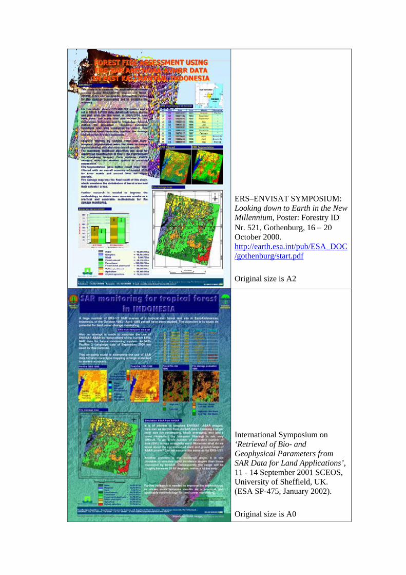
ERS–ENVISAT SYMPOSIUM: Looking down to Earth in the New Millennium, Poster: Forestry ID Nr. 521, Gothenburg, 16 − 20 October 2000. http://earth.esa.int/pub/ESA_DOC/gothenburg/start.pdf
Original size is A2
International Symposium on ‘Retrieval of Bio- and Geophysical Parameters from SAR Data for Land Applications’, 11 - 14 September 2001 SCEOS, University of Sheffield, UK. (ESA SP-475, January 2002).
Original size is A0
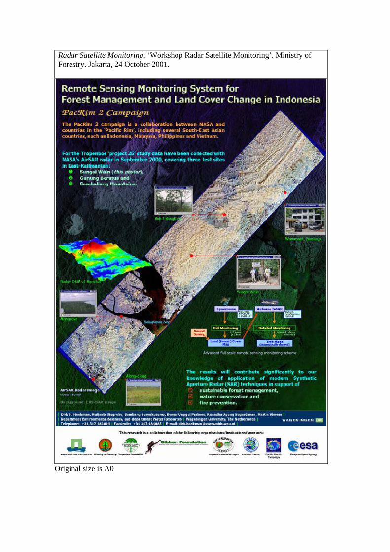
Radar Satellite Monitoring. ‘Workshop Radar Satellite Monitoring’. Ministry of Forestry. Jakarta, 24 October 2001.
Original size is A0

The Second Indonesian Airborne Radar Experiment (INDREX-2) Experimental radar provides 3-D forest view over Mawas, Gunung Meratus, Sungai Wain, Balikpapan Bay Mangrove, Samboja Lestari. November 2004.
Original size is A0 http://www.esa.int/esaEO/SEMHWDXEM4E_index_0.html INDREX-2 involved flying a test instrument called the Experimental Synthetic Aperture Radar (E-SAR), built by the German Aerospace Centre (DLR), in a Dornier-228 aircraft over test sites area around Kalimantan.
Related Documents