Space Air Diffusion II Dr. Sam C. M. Hui Department of Mechanical Engineering The University of Hong Kong E-mail: [email protected] Jan 2015 MEBS6008 Environmental Services II http://www.mech.hku.hk/bse/MEBS6008/

Welcome message from author
This document is posted to help you gain knowledge. Please leave a comment to let me know what you think about it! Share it to your friends and learn new things together.
Transcript
Space Air Diffusion IIDr. Sam C. M. Hui
Department of Mechanical EngineeringThe University of Hong Kong
E-mail: [email protected] 2015
MEBS6008 Environmental Services IIhttp://www.mech.hku.hk/bse/MEBS6008/

Contents
• Cold Air Distribution• Displacement Flow• Underfloor Air Distribution• Unidirectional Flow• Projecting Flow• Air Flow Analysis

Cold Air Distribution
• Lower supply air temp. = 4.4 to 7.2 oC• Conventional air distribution = 12.7 to 15.0 oC• Applied mainly in conjunction with ice storage
systems• Lower chw temp. (1.1 to 2.2 oC) (from ice storage)
• Main advantages:• Reduce design supply volume flow (larger ΔT)• Air-side components can be downsized• Fan energy use can be reduced• Reduced fan sound levels
• Drawbacks: dumping of cold air jet & IAQ issues

Cold Air Distribution
• Design considerations• Condensation
• Cooled surfaces shall be well insulated & sealed• Comfort
• Air supplied at lower velocities: diffuser performance isaffected (e.g. dumping & stagnant at low load)
• Indoor air quality• Minimum ventilation flow is required; may need reheat
• Controls• Start-up & shut-down, humidity controls, VAV, etc.

Cold Air Distribution
• Two methods for cold air space diffusion• High induction nozzle diffusers
• Direct from AHU or package unit• Fan-powered VAV boxes
• Mix low-temperature supply air with return air before supplied tothe conditioned space
• Characteristics of cold air distribution• Higher √Ar / Do value• Higher supply air velocity & jet turbulence• Good surface effect (adequate throw, small drop)• ADPI ≥ 80 at both design & reduced airflow

Series flow fan power terminal(Source: http://www.price-hvac.com)
Cold Air Distribution
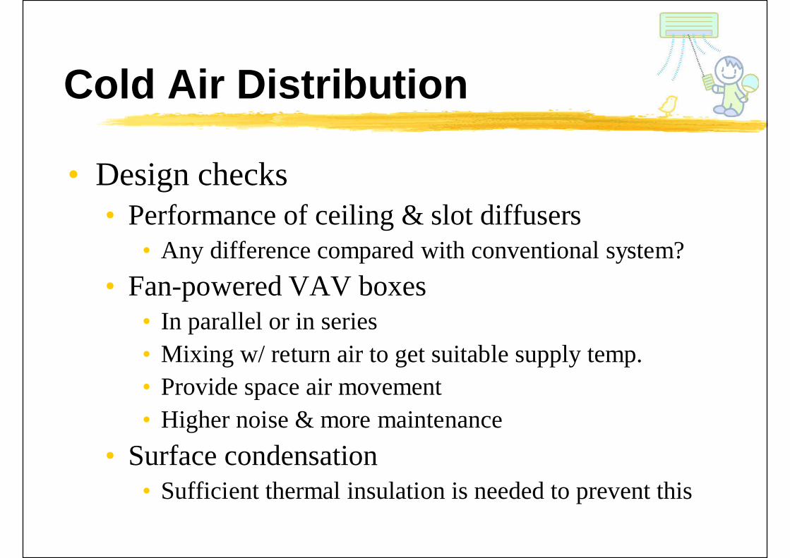
• Design checks• Performance of ceiling & slot diffusers
• Any difference compared with conventional system?• Fan-powered VAV boxes
• In parallel or in series• Mixing w/ return air to get suitable supply temp.• Provide space air movement• Higher noise & more maintenance
• Surface condensation• Sufficient thermal insulation is needed to prevent this

Displacement Flow
• Displacement flow• Cold supply air at a velocity nearly equal to the
required velocity and displace the original air withpiston-like airflow w/o mixing
• If properly designed, it can give:• Better IAQ in occupied zone• Higher space diffusion effectiveness• Low turbulence intensities & fewer draft problems
• Drawbacks:• Require greater supply volume flow rate• Higher construction cost

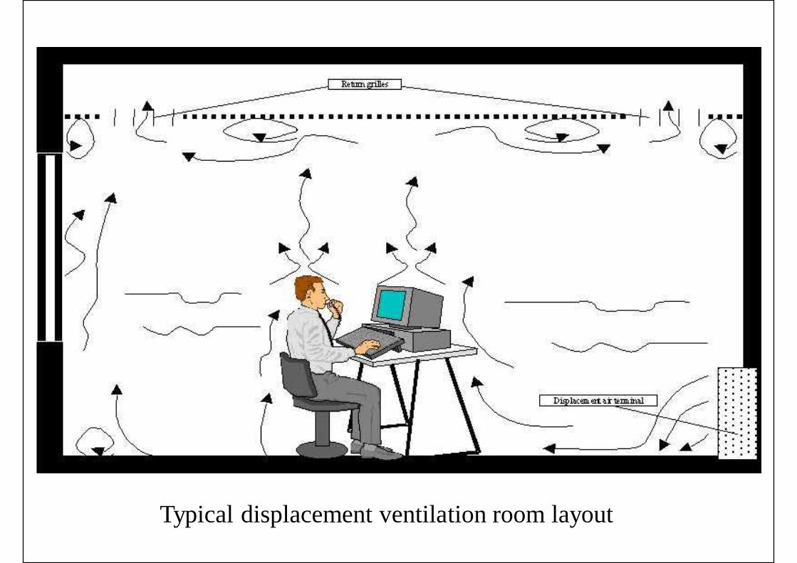
Typical displacement ventilation room layout

Displacement flow characteristics(Source: http://www.price-hvac.com)

Displacement ventilation system

Displacement Flow
• Airflow patterns• Because of low discharge velocity, air motion is
influenced to a large degree by convection flows• Convection flows (or thermal plumes) are created by
heat sources, e.g. people, equipment, warm windows• Cold sinks (e.g. cold windows) may create flows down
• Airflow penetration• Supply air spread across the floor in a thin layer,
filling the entire space• Flow around & beyond obstructions

Displacement flow patterns(Source: http://www.price-hvac.com)

(Source: http://www.price-hvac.com)Airflow penetration

Displacement Flow
• Diffuser airflow patterns• To avoid draft, displacement diffuser shall deliver
the supply air uniformly at low velocity• With internal equalization baffle & low free area face
• For cool air supply, it will falls towards the floor• For isothermal air, it will distribute horizontally• For heated air, the discharge air will rise
• Therefore, it is not recommended to supply heated air

(Source: http://www.price-hvac.com)Displacement diffuser airflow pattern

Displacement Flow
• Contaminant distribution• Can reduce contaminant in lower portion of room• Actual distribution is influenced by factors e.g.
contaminant source type & location, human bodyconvection and space height, strength of thermalplume
• Ventilation effectiveness• Displacement can achieve around 1.2-1.4; most
mixing systems is around 1.0

(Source: http://www.price-hvac.com)

Displacement Flow
• Temperature distribution• Temperature gradient between the floor & ceiling• Also known as “Stratification”• Affected by factors e.g. supply air volume, room
cooling load, location & type of heat source, heightof the space
• Controlling stratification is critical to maintainthermal comfort
• If heating is needed, may use radiator to offsetcold downdrafts near the windows
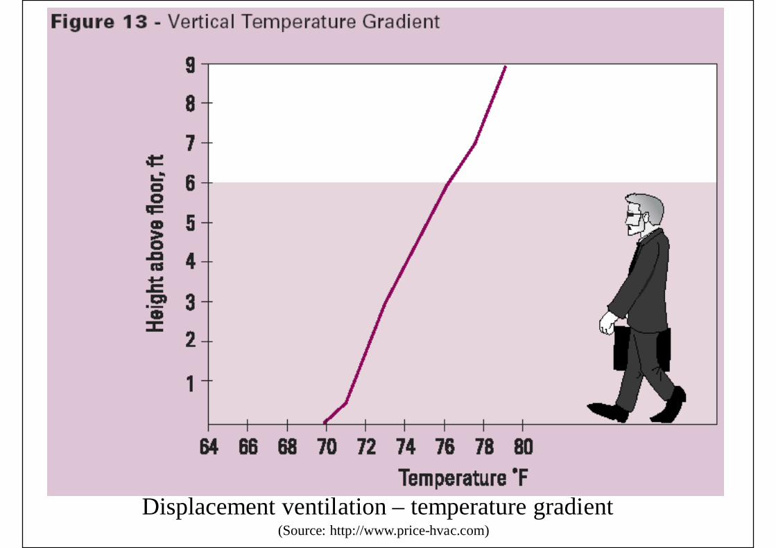
(Source: http://www.price-hvac.com)Displacement ventilation – temperature gradient

(Source: http://www.price-hvac.com)Displacement ventilation – temperature gradient

(Source: http://www.price-hvac.com)Displacement ventilation and radiator

Displacement Flow
• Stratified displacement flow• First introduced in Scandinavian countries• Low-level supply outlet• Above heat & contaminated sources
• Heated air rises upward due to buoyancy effect• Supply air is entrained into the upward convective flow• Stationary level: upward flow = supply flow• Two-zone stratified model: upper zone & lower zone

Stratified displacement flow in a typical room

Displacement Flow
• Characteristics of stratified displacement flow• Cold air supply of usually 100% outdoor air• Air must be supplied at low velocity (< 0.3 m/s) &
at a height less than 0.54 m above floor• Cold air supplied at 2.8 to 5 oC lower than
occupied zone• Height of lower zone shall be higher than a seated
occupant (1.4 m); all air is supply air in lower zone• Smaller cooling load density (max. 41 W/m2)• Return or exhaust inlets located near ceiling level

Displacement Flow
• Design procedure• Step 1: determine summer cooling load
• Occupants, lights, equipment, envelope• Step 2: determine cooling load ventiln. flow rate
• Equation from the ASHRAE design guide• Step 3: determine flow rate of fresh air• Step 4: determine supply air flow rate
• Max {Step 2, Step 3} flow rates• Step 5: determine supply air temperature• Step 6: determine exhaust air temperature

Displacement Flow
• Common diffuser types• Rectangular units• Corner units• Semi-circular units• Circular units• Floor mounted units

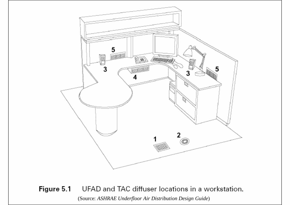
Underfloor Air Distribution
• Upward flow underfloor air distribution• Conditioned air from floor plenum (0.3-0.45 m)
• Usually ductless (air duct has also been used in the past)
• Supply outlets• Floor diffusers, fan-driven units, desktop units, supply outlets from
fan coil units and water-source heat pumps• Often partial displacement & partial mixing
• Cool primary air from AHU• Applications of underfloor air distribution
• Computer rooms air conditioning• Commercial buildings (w/ access raised floor systems)

Upward flow underfloor air distribution system
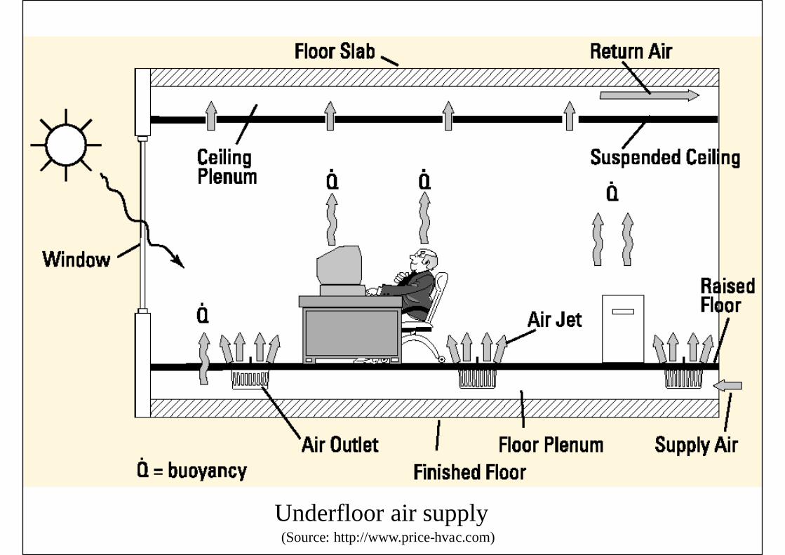
(Source: http://www.price-hvac.com)Underfloor air supply

(Source: ASHRAE Underfloor Air Distribution Design Guide)
Underfloor air distribution system

(Source: ASHRAE Underfloor Air Distribution Design Guide)Office space with underfloor air distribution & task air-conditioning
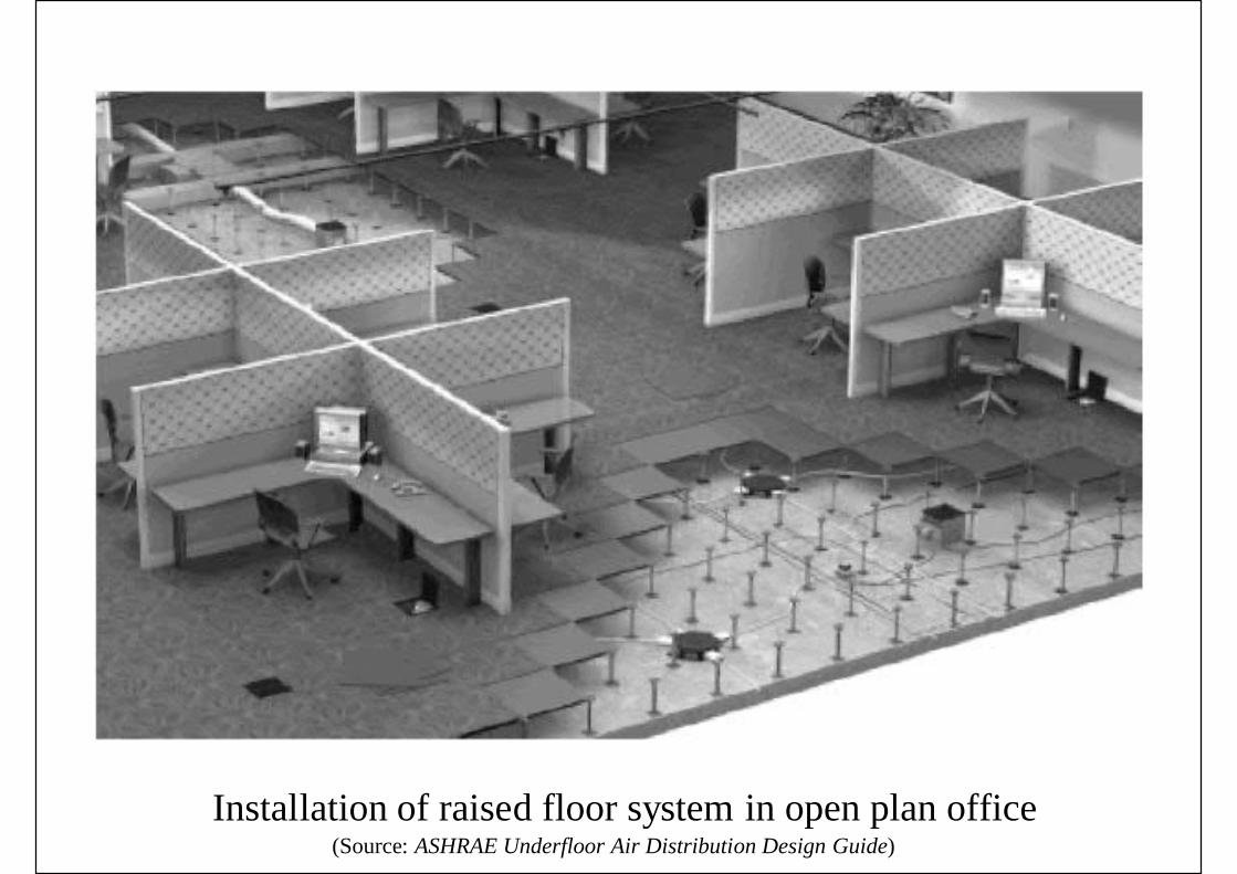
(Source: ASHRAE Underfloor Air Distribution Design Guide)Installation of raised floor system in open plan office
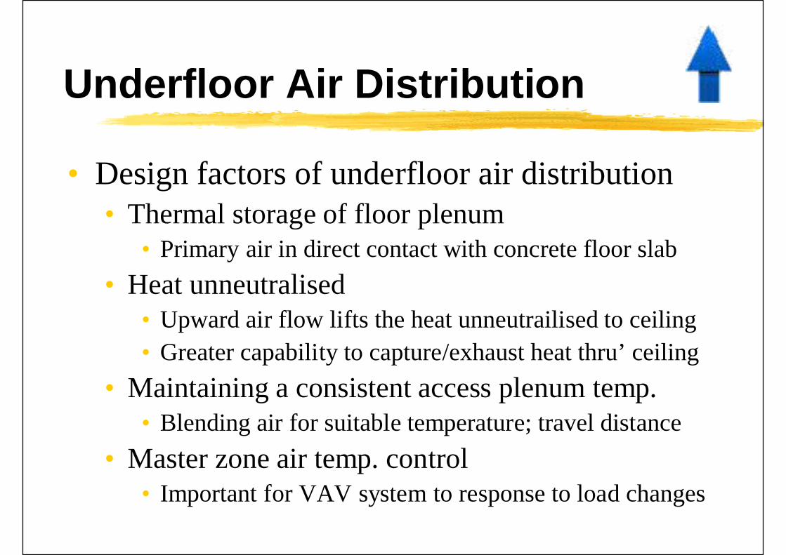
Underfloor Air Distribution
• Design factors of underfloor air distribution• Thermal storage of floor plenum
• Primary air in direct contact with concrete floor slab• Heat unneutralised
• Upward air flow lifts the heat unneutrailised to ceiling• Greater capability to capture/exhaust heat thru’ ceiling
• Maintaining a consistent access plenum temp.• Blending air for suitable temperature; travel distance
• Master zone air temp. control• Important for VAV system to response to load changes

Underfloor Air Distribution
• Advantages of underfloor air distribution• Integrated well with raised floor plenum• Can be very flexible for future changes/relocations• Conditioned air is supplied directly to occupants• Stagnant air can be reduced (if ceiling return)• Upward flow lifts some unneutralised heat• It can utilise thermal mass of access floor & slab to reduce
peak demands• Disadvantages
• Higher initial costs• Need for raised floor system & floor diffusers
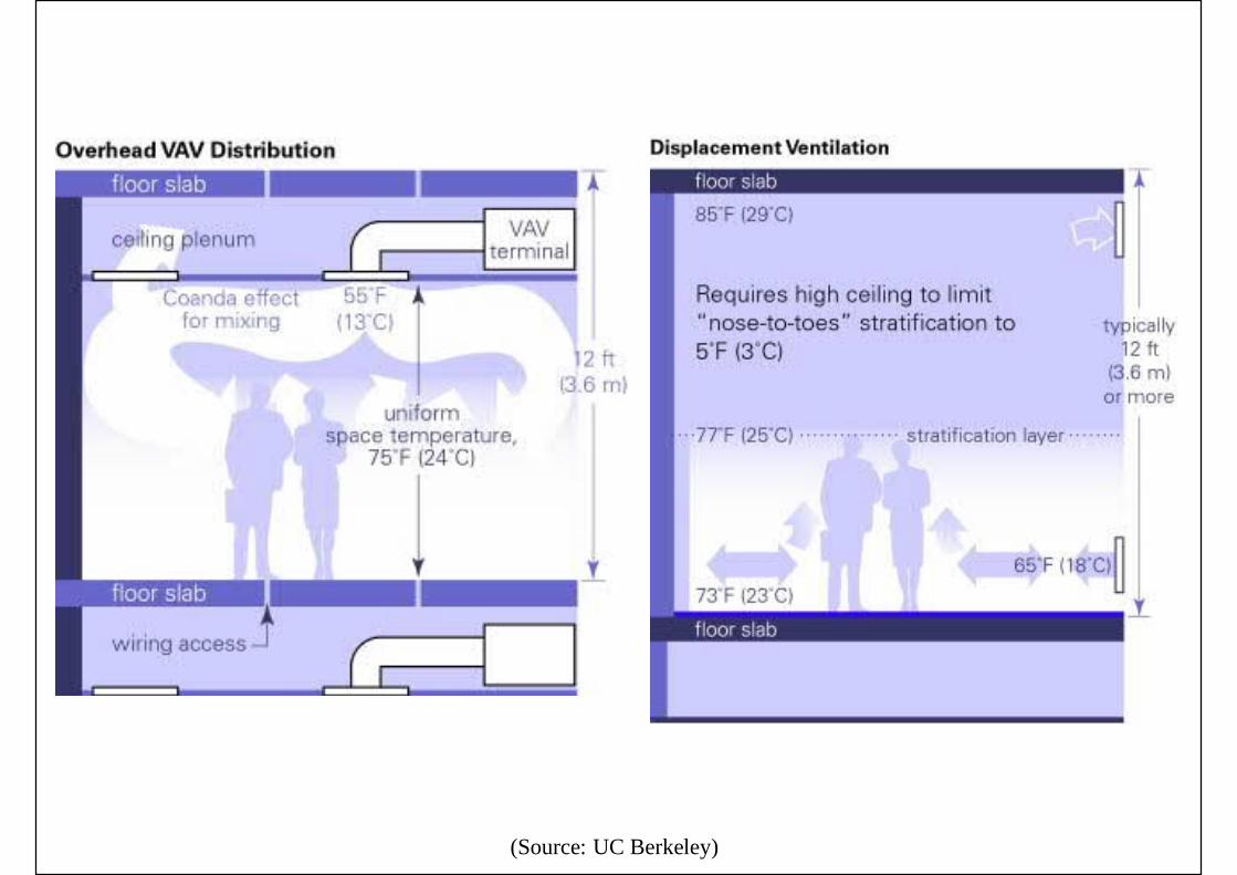
(Source: UC Berkeley)

(Source: UC Berkeley)

(Source: ASHRAE Underfloor Air Distribution Design Guide)Comparison of typical vertical temperature profiles

References
• ASHRAE design guides:• ASHRAE, 2013. UFAD Guide: Design Construction and
Operation of Underfloor Air Distribution Systems• Bauman, F. S. and Daly, A., 2003. Underfloor Air
Distribution Design Guide• Chen, Q. and Glicksman, L., 2003. System Performance
Evaluation and Design Guidelines for DisplacementVentilation
• Suppliers information:• http://www.priceindustries.com• http://www.flexiblespace.com

Unidirectional Flow
• Unidirectional flow• Airstream flows in the same direction as uniform
airflow showers the entire working area oroccupied zone (known as “laminar flow”)
• Examples:• Clean rooms (downward or horizontal flow)• Ventilating or perforated ceiling
• Advantages:• Contaminants generated cannot move laterally• Dust particles will not be carried to higher levels

Unidirectional flow for clean rooms(Source: Wang, S. K., 2001. Handbook of Air Conditioning and Refrigeration)

Ventilating ceiling
(Source: Wang, S. K., 2001. Handbook of Air Conditioning and Refrigeration)
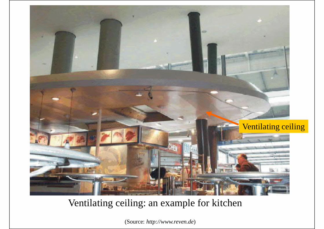
Ventilating ceiling: an example for kitchen
(Source: http://www.reven.de)
Ventilating ceiling
Unidirectional Flow
• Ceiling plenum & supply air velocity• To create a more uniform supply air velocity, the
max. air velocity inside the ventilating ceilingplenum shall be low
• If sufficient plenum height & few obstructions,distributing ductwork inside is not needed
• Applications of ventilating ceiling• Industrial process• Indoor sports stadium for badminton (< 0.2 m/s)
Unidirectional Flow
• Hospital applications (more critical)• Main purpose: control of airborne contaminants• Such as operating theatre and isolation wards
• Operating theatre• Large fresh air ventilation (100% outdoor air)• Large volume of supply air• At low uniform velocity to promote stable
downward flow of air

Flow patterns in hospital operating theatre
(Source: http://www.price-hvac.com)
Laminar flow -full ceilingsupply
Laminar flow -partial ceilingsupply

Hospital operating theatre (laminar flow with air curtains)(Source: http://www.price-hvac.com)
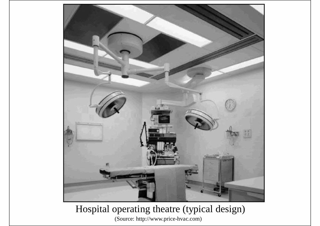
Hospital operating theatre (typical design)(Source: http://www.price-hvac.com)

Hospital operating theatre (typical design)(Source: http://www.price-hvac.com)

Unidirectional Flow
• Hospital applications - isolation wards• Infectious isolation rooms
• Patients with infectious diseases• Kept at a negative pressure
• Protective isolation rooms• Patients with a high susceptibility to infection• Kept at a positive pressure
• HEPA filters will be used• Ante rooms are recommended to minimize exchange of air
between a hallway and the isolation room• Airflow pattern: protect health care staff or patient
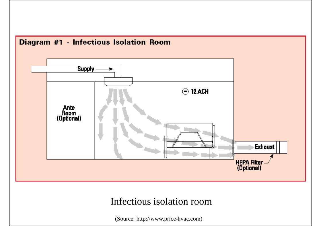
Infectious isolation room(Source: http://www.price-hvac.com)

Protective isolation room(Source: http://www.price-hvac.com)

SARS test chamber (inside HKU BSE Lab)

Projecting Flow
• Cold or warm air jet projected to target zone• Benefits of projecting flow
• Better control of temp., air cleanliness & airmovement in a localised environment
• Spot cooling improve occupants’ thermalconditions & reduce heat stress
• Greater direct outdoor air supply• Direct & efficient handling of local loads• Greater control of their own micro-environment

Projecting Flow
• Disadvantages of projecting flow• Draft discomfort or pressure air jet• Limited area of environmental control• More complicated space air diffusion design
• Usually free jets with high entrainment ratios• Long-throat round nozzles are often used
• Two types of projecting flow• Industrial spot cooling systems• Desktop task air conditioning systems
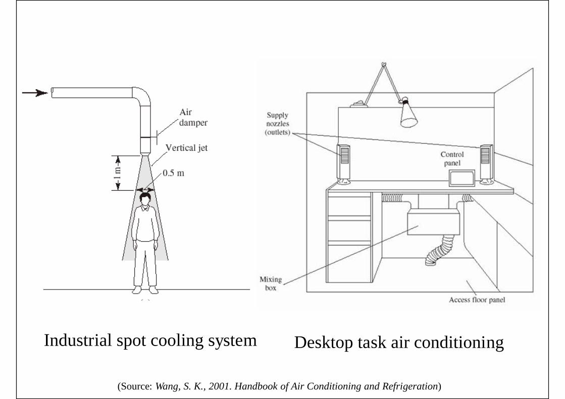
Industrial spot cooling system Desktop task air conditioning
(Source: Wang, S. K., 2001. Handbook of Air Conditioning and Refrigeration)

Projecting Flow
• Industrial spot cooling systems• Temperature difference between target zone & the
room air is often 2.8 oC or greater• Distance between target zone & supply outlet• Vertical vs horizontal jet• Target velocities• Thermal sensation
• Of whole body & for individual parts (local)
• Allow occupants to have individual control

Projecting Flow
• Desktop task conditioning systems• Also task/ambient conditioning (TAC)• Typical design: self-powered mixing box, small
supply fans, desktop supply outlets (nozzles),flexible ducts + control panel
• Also integration with furniture or partitions• Advantages:
• Allow occupants to fine-tune the local environment• Possible to off the unit when unoccupied to save energy• Direct supply of primary air to occupants

(Source: ASHRAE Underfloor Air Distribution Design Guide)
(Source: ASHRAE Underfloor Air Distribution Design Guide)

(Source: ASHRAE Underfloor Air Distribution Design Guide)

Air Flow Analysis
• Computational fluid dynamics (CFD)*• Computing technique for analysis & prediction of
fluid motion and heat transfer• Using Navier-Stokes & thermal equations
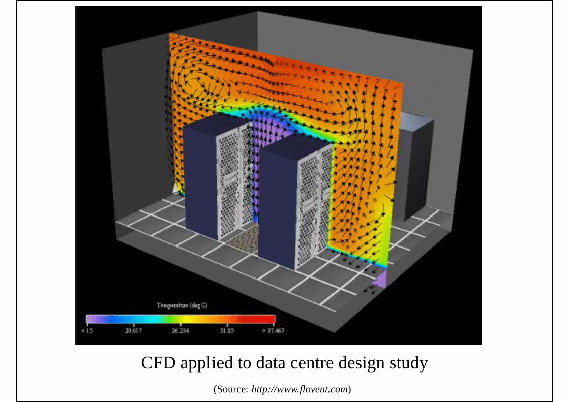
• Become more and more popular for study of airflow patterns, indoor temperature distribution &indoor contaminants
• Useful tool for studying space air diffusion
* Video: Computational Fluid Dynamics (CFD) (3:32) https://www.youtube.com/watch?v=hzTCCcsOTg8http://www.learnengineering.org/2013/05/What-is-CFD-computational-fluid-dynamics.html

(Source: Dr. Yuguo Li, Dept of Mech Engg, HKU)
CFD visualisation – temp. distribution (St. James Theatre, Australia)
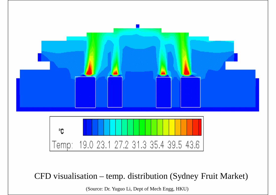
(Source: Dr. Yuguo Li, Dept of Mech Engg, HKU)
CFD visualisation – temp. distribution (Sydney Fruit Market)

Computational fluid dynamics (CFD) applied to airflow study
(Source: http://www.fluent.com/)

(Source: http://www.flovent.com)
CFD applied to naturally ventilated buildings
(Source: http://www.flovent.com)
CFD applied to data centre design study

Air Flow Analysis
• Computational fluid dynamics (CFD)• Turbulence modelling methods
• Correlations, e.g. drag as a function of Re• Integral methods• Reynolds average models (κ-ε models)
• Large eddy simulation (LES)• Direct numerical simulation (DNS)
• Time average Navier-Stokes equations*• Incompressible form of the momentum equation• Full and general set of partial differential equations
governing fluid motion* Video: Computational Fluid Dynamics (CFD) | RANS & FVM (5:21) https://www.youtube.com/watch?v=YGuLvNWKk2k
http://www.learnengineering.org/2013/05/computational-fluid-dynamics-rans-fvm.html

Air Flow Analysis
• Computational fluid dynamics (CFD)• Governing equations:-
• Mass balance:• Momentum:
• Energy:
0)()()( =¶¶
+¶¶
+¶¶
+¶¶ W
zV
yU
xtrrr
r
)()()()( UWz
UVy
UUx
Ut
rrrr¶¶
+¶¶
+¶¶
+¶¶
xgz
WyV
xU
xzU
zyU
yxU
xxP
rmmmm +úû
ùêë
é÷÷ø
öççè
涶
+¶¶
+¶¶
¶¶
+¶¶
¶¶
+¶¶
¶¶
+¶¶
¶¶
+¶¶
-=31)()()(
)()()()()()()(***
****
zzyyxxW
zV
yU
xt ¶T
G¶¶
+¶T
G¶¶
+¶T
G¶¶
=T¶¶
+T¶¶
+T¶¶
+T¶¶
rrrr
Fluid density (ρ) Velocity (U, V, W)
Viscosity (μ)x-momentumy-momentumz-momentum
Temperature (T*) Diffusivity (Γ)
References
• The Basics of Computational Fluid DynamicsModeling• http://www.flow3d.com/CFD-101/CFD101.htm
• Navier-Stokes Equations (Foundations of FluidMechanics)• http://www.navier-stokes.net/
• FLOVENT Applications• http://www.flovent.com/applications/
Related Documents