May 20,2004 Page 1 of 52 R 26 7 Accessories 7.1DRIVERS 7.1.1General 7.1.1.1 The driver shall be of the type specified, shall be sized to meet the maximum specified operating conditions, including external gear and coupling losses, and shall be in accordance with applicable specifications, as stated in the inquiry and order. The driver shall operate under the utility and site conditions specified in the inquiry. 7.1.1.2 The driver shall be sized to accept any specified process variations such as changes in the pressure, temperature or properties of the fluids handled, and plant start-up conditions. 7.1.1.3 The driver shall be capable of starting under the conditions specified and the starting method shall be agreed by the purchaser and the vendor. The driver's starting-torque capabilities shall exceed the speed-torque requirements of the driven equipment. Discussion: The worst case conditions need to be considered for all drivers. These are generally covered in the following paragraphs: 7.1.2–7.1.4. 7.1.1.4 The supporting feet of drivers with a weight greater than 225 kg,(500lbs) shall be provided with vertical jackscrews. 7.1.2 Motors •7.1.2.1 Motor drives shall conform to Internationally recognized standards such as API Standard 541 or 546 or other internationally recognized standard as approved by the purchaser as applicable.(Motors that are below the power scope of API Std 541 or 546 shall be in accordance with IEEE 841 or IEC 60034 ). Electric motor drivers shall be rated w/a 1.0 S.F. The motor rating shall be at least 110% of the greatest power required (including gear and coupling losses) for any of the specified 2/25/2022

Welcome message from author
This document is posted to help you gain knowledge. Please leave a comment to let me know what you think about it! Share it to your friends and learn new things together.
Transcript

May 20,2004 Page 1 of 38R 26
7 Accessories7.1 DRIVERS
7.1.1General
7.1.1.1 The driver shall be of the type specified, shall be sized to meet the maximum specified operating conditions, including external gear and coupling losses, and shall be in accordance with applicable specifications, as stated in the inquiry and order. The driver shall operate under the utility and site conditions specified in the inquiry.
7.1.1.2 The driver shall be sized to accept any specified process variations such as changes in the pressure, temperature or properties of the fluids handled, and plant start-up conditions.
7.1.1.3 The driver shall be capable of starting under the conditions specified and the starting method shall be agreed by the purchaser and the vendor. The driver's starting-torque capabilities shall exceed the speed-torque requirements of the driven equipment.
Discussion: The worst case conditions need to be considered for all drivers. These are generally covered in the following paragraphs: 7.1.2–7.1.4.
7.1.1.4 The supporting feet of drivers with a weight greater than 225 kg,(500lbs) shall be provided with vertical jackscrews.
7.1.2 Motors
•7.1.2.1 Motor drives shall conform to Internationally recognized standards such as API Standard 541 or 546 or other internationally recognized standard as approved by the purchaser as applicable.(Motors that are below the power scope of API Std 541 or 546 shall be in accordance with IEEE 841 or IEC 60034). Electric motor drivers shall be rated w/a 1.0 S.F. The motor rating shall be at least 110% of the greatest power required (including gear and coupling losses) for any of the specified operating conditions. Consideration shall be given to the starting conditions of both the driver and driven equipment and the possibility that these conditions may be different from the normal operating conditions.NOTE The 110% applies to the design phase of a project. After testing, this margin might not be available due to performance tolerances of the driven equipment.
Note to Task Force Chairman: If your standard requires drivers less than 250 horsepower insert the applicable industry standard reference, since API 540 covers motors 250 horsepower and higher.
Discussion: Some purchasers use 115% of maximum power required or the next larger frame size(not including service factor), to take advantage of increased capacity at a slight increase in cost.
7.1.2.2 The purchaser shall specify the type of motor and its characteristics and accessories, including but not limited to the following:
5/7/2023

May 20,2004 Page 2 of 38R 26
a. Electrical characteristics.b. Starting conditions (including the expected voltage drop on starting).c. The type of enclosure.d. The sound pressure level.e. The area classification, based on API Recommended Practice 500A or equivalent international standard.f. The type of insulation.g. Add purchas std [see 610]h. The ambient temperature and elevation above sea level.i. Transmission losses.j. Temperature detectors, vibration sensors, and heaters specifiedk. Auxiliaries (such as motor-generator sets, ventilation blowers, and instrumentation).l. Vibration acceptance criteria.m. Use in variable frequency drive applications.Note to task force chairmen: If the equipment covered in your standard uses API Standard 541 or 546, paragraph 7.1.2.2 is not required. If the equipment in your standard does not use 541 or 546, keep 7.1.2.2 in your standard.
Discussion: This is a partial check list and the user should consult individual standards for additional requirements. The purchaser should use a larger size motor if a VFD is too costly.
7.1.2.3 The motor's starting torque shall meet the requirements of the driven equipment, at a reduced voltage of 80% of the normal voltage, or such other value as may be specified, and the motor shall accelerate to full speed within 15 seconds or such other period of time agreed upon by the purchaser and the vendor.
Discussion: The actual time to accelerate the motor during starting is dependent upon the difference between the speed torque of the motor and the driven equipment. Motor accelerating torque is affected by the motor terminal voltage. Refer to API Std 546 for the minimum required difference.
No bullet added because this is default paragraph.
7.1.3 Steam Turbines
7.1.3.1 Steam turbine drivers shall conform to ISO 10437 API611 or 612. Steam turbine drivers shall be sized to deliver continuously not less than 110% of the maximum power requirement of the driven equipment, (including any gear and coupling losses) when operating at any of the specified operating conditions, with the specified normal steam conditions. [API 672]NOTE The 110% applies to the design phase of the project. After testing, this margin might not be available due to performance tolerances of the driven equipment.
Discussion: The last sent was added to make consistent with the note in 7.1.2. which also discusses the 110% capability.
Discussion: It is to be considered with the normal steam conditions. API Standards require that the rated power of the driven equipment, at its corresponding speed, be developed with minimum inlet and maximum exhaust steam conditions.
5/7/2023
May 20,2004 Page 3 of 38R 26
Discussion: ISO 10437 has been withdrawn from the ISO work schedule.
7.1.4 Gas Turbines
7.1.4.1 Gas turbine drivers shall conform to API Std 616 and shall be sized as agreed by the purchaser and the vendor taking account of site conditions, particularly variations in ambient air temperatureNote to Task Force Chairman: SOME voted negative on ISO 3977 Section 5 and therefore should not reference it in our documents.
7.1.5 Gear Units
7.1.5.1 Gear units shall conform to API Std 613 .ISO 13691 [API Std 613 & 677]Discussion: Delete reference to ISO 13691, it is not equivalent to API613. ISO 13691 is like an API613 4-1/2 edition vs. API 613 5th. Also, I have not found anyone who has ever bought a gearbox built to ISO 13691.[Wes Conner]
7.2 COUPLINGS AND GUARDS
7.2.1 Unless otherwise specified, non lubricated flexible element couplings and guards between drivers and driven equipment shall be supplied by the manufacturer of the driven equipment. [API 677]
Discussion: Modification to 7.2.1 eliminates grease cplgs due to the 5 year continuous operation requirement in the 6.1.1.
7.2.2 Couplings for special purpose applications shall conform to ISO 10441 [API 671] The make, type and mounting arrangement shall be agreed by the purchaser and the vendors of the driver and driven equipment. NOTE For the purpose of this provision, API 671 is equivalent to ISO 10441.
[Eliminated reference to ISO 14691 GP Cplg specification since SOME negatively balloted it ].
7.2.3 Couplings for general purpose applications shall be all-metal flexible element, spacer-type couplings manufactured to meet AGMA 9 000 Class 9 and shall comply with the following:a) Flexible elements shall be of corrosion-resistant material.b) Couplings shall be designed to retain the spacer if a flexible element ruptures.c) Coupling hubs shall be steel.d) The distance between the driven and driver shaft ends (distance between shaft ends, or DBSE) shall be at least 125 mm (5 in) and shall permit removal of the coupling, bearings, seal and rotor, as applicable, without disturbing the driver, driver coupling hub or the suction and discharge piping. This dimension, DBSE, shall always be greater than the minimum total seal length.
NOTE The DBSE dimension usually corresponds to the nominal coupling spacer length.
e) Provision shall be made for the attachment of alignment equipment without the need to remove the spacer or dismantle the coupling in any way.
5/7/2023

May 20,2004 Page 4 of 38R 26
NOTE One way of achieving this is to provide at least 25 mm (1 in) of bare shaft between the coupling hub and the bearing housing where alignment brackets may be located.
f) Couplings operating at speeds in excess of 3 800 r/min shall meet the requirements of API 671 for component balancing and assembly balance check. [API 610 & ISO DIS 13709:2005]
• g) If specified, couplings shall be balanced to ISO 1940-1 grade G6.3.
[a-g fromAPI 610]
Note To Task Force Chairman: Information pertaining to guards can be found in the Appendix of API Std 671. If your standard covers special purpose equipment reference API Std. 671. If your standard covers general purpose equipment reference ISO 14691. We can not reference ISO 10441 (which covers SP couplings) as an entire document since we negative balloted it. You can reference certain paragraphs in it however.
7.2.4 Information on shafts, keyway dimensions (if any), and shaft end movements due to end play and thermal effects shall be furnished to the vendor supplying the coupling.NOTE This information is normally furnished by the vendor of the driven equipment or the driver vendor.
Discussion: Various parties take on different roles of responsibility to establish an acceptable design of the system.
7.2.5 The couplings and coupling-to-shaft juncture shall be designed and manufactured to be capable of transmitting power at least equal to the power rating of the motor including service factor. [API 614 & 610]
7.2.6 The purchaser of the coupling shall provide or include an idling adapter, as required for the mechanical running test (see 8.3.3.1.8).
Discussion Coupling vendor usually furnishes the adapter. However, this option is open for the coupling and equipment vendor.
7.2.7 Coupling mountings shall conform to ISO 10441 [API 671], for special purpose applications. Unless otherwise specified, the couplings for general purpose equipment shall be mounted in accordance with the requirements of 7.2.7.1 through 7.2.7.5. For a tapered-hub coupling, the vendor shall provide a plug gauge from a matched plug and ring set, for the purpose of checking the bore of the hub, unless an alternative method of ensuring a correct fit has been agreed.
7.2.7.1 Flexible couplings shall be keyed to the shaft. Keys and keyways and their tolerances shall conform to AGMA 9002, Commercial Class).
7.2.7.2 Flexible couplings with cylindrical bores shall be mounted with an interference fit. Cylindrical shafts shall comply with (AGMA 9002) and the coupling hubs shall be bored to the following tolerances (ISO 286-2): [ISO R 775 withdrawn]a. For shafts of 50mm (2 in)diameter and smaller—Grade N7b. For shafts larger than 50 mm (2 in) diameter—Grade N8
5/7/2023

May 20,2004 Page 5 of 38R 26
7.2.7.3 Where servicing (such as for mechanical seal) requires removal of the coupling hub from the shaft, and the shaft diameter is greater than 60 mm (2.5 in), the coupling hub shall be a taper fit. Taper for keyed couplings shall be 1/10 conical, long series, in accordance with ISO R775 or alternately 1/16 (0.75 in /ft, diametrical) for compliance with U.S. standards.
7.2.7.4 Coupling hubs shall be furnished with tapped puller holes at least 10 mm (0.375in) diameter to facilitate removal.
7.2.8 Each coupling shall have a coupling guard which is removable without disturbing the coupled elements and shall meet the requirements of :7.2.8.1 through 7.2.8.3 [API 610] .
• 7.2.8.1 Coupling guards shall enclose the coupling and the shafts to prevent personnel from contacting moving parts during operation of equipment train. Allowable access dimensions shall comply with specified standards, such as ISO 14120, EN 953 or ASME B15.1.
7.2.8.2 Guards shall be constructed with sufficient rigidity to withstand a 900 N (200 lbf) static point load in any direction without the guard contacting moving parts.
• 7.2.8.3 Guards shall be fabricated from solid sheet or plate with no openings. Guards fabricated from expanded metal or perforated sheets may be used if the size of the openings does not exceed 10 mm (0,375 in). Guards shall be constructed of steel, brass or nonmetallic (polymer) materials. Guards of woven wire shall not be used. If specified, non-sparking guards of agreed material shall be supplied.
Discussion: Requirements listed in 7.2.8are intended for general purpose equipment and are derived from the requirements for special purpose equipment (see API Standard 671).Guard requirements for special purpose equipment is found in API 671 and need not be repeated here for SP equipment.
Discussion: When specifying non sparking material for guards, monel is the only metal considered non sparking and it is suitable for fabricating a guard.
SPTF HOLD the following paragraph
“6.8.5.5 Bearing housings shall be equipped with replaceable labyrinth-type end seals and deflectors where the shaft passes through the housing; lip-type seals shall not be used. The seals and deflectors shall be made of spark resistance non-sparking materials. The design of the seals and deflectors shall effectively retain oil in the housings and prevent entry of foreign material into the housing.
NOTE - Many users consider pure aluminium and aluminium alloys with a maximum content of 2% magnesium or 0.2% copper, copper and copper-based alloys (e.g. brass, bronze) to be spark resistant. However, local regulations, such as EN 13463-1, may not allow aluminium or non-metallic materials within potentially explosive atmospheres. (RLJ: Suggest wording
5/7/2023

May 20,2004 Page 6 of 38R 26
change and also adoption of wording as a standard paragraph for coupling guards.)” Suggested by Curt Goude. 673. SPTF to review
7.3 BELT DRIVES
7.3.1 Belt drives shall only be used for equipment of 150 kw (200 brake horsepower) or less and require purchasers approval. Unless otherwise specified, timing type belts and sheaves shall be provided All belts shall be of the static-conducting type and shall be oil resistant. The drive service factor shall not be less than 1.75 based on the driver nameplate power rating. [618]NOTE Oil resistant belts require a core of Neoprene or an equivalent material.
Discussion: Torque transmission requires multiple V belts to be used. For each belt to transmit the same torque, matched sets of individual belts, individual belts banded together in a banded multi-V belt design or multiple banded multi-V belts are required. Banded multi- V belts are required in lieu of matched sets of individual belts for easier maintenance. There is more chance of losing or misplacing one belt in a matched set than one entire bandedmulti-V belt.
V-belts also impose high side loading on the radial bearings. When using V-belts, the radial bearings therefore have to be upgraded. Additionally, the banded V-belt design imparts a higher load than matched sets of individual belts. It is not uncommon therefore that ball bearings are upgraded to roller bearings when belt drives are used. One should not change from matched sets of individual belts to a banded design without checking the load - carrying capability of the radial bearings.
7.3.2 The vendor shall provide a positive belt-tensioning device. This device shall incorporate a lateral adjustable base with guides and hold-down bolts, two belt-tensioning screws, and locking devices. All bearing lubrication points shall be accessible. [618 9th Edition]
Discussion: Although other belt tensioning devices have been provided, they are not always reliable.
7.3.3 When a belt drive is to be used, the vendor who has unit responsibility shall inform other manufacturers of the connected equipment. The other manufacturer(s) shall be provided with the radial load resulting from the belt drive and, for reciprocating machines, the vibratory torque characteristics. The drive manufacturer shall take into account the radial load and torque variation conditions and shall provide bearings with a life at least equivalent to that specified in 6.9.1.
7.3.4 Belt drives shall meet the requirements of 7.3.4.1 through 7.3.4.7.
7.3.4.1 The distance between the centers of the sheaves shall be at least 1.5 times the diameter of the larger sheave.
5/7/2023
May 20,2004 Page 7 of 38R 26
Discussion: If the distance is less than 1.5 there might be insufficient arc of contact. [API 618]
7.3.4.2 The belt wrap (contact) angle on the smaller sheave shall be at least 140°.
7.3.4.3 The shaft length on which the sheave hub is fitted shall be at least equal to the width of the sheave hub.
Discussion: The sheave hub should not overhang the end of the shaft.7.3.4.4 The length of a shaft key used to mount a sheave shall be equal to the length of the sheave bore.
7.3.4.5 Unless otherwise agreed or specified, each sheave shall be mounted on a tapered adapter bushing.
7.3.4.6 To reduce the moment on shafts due to belt tension, the sheave overhang distance from the adjacent bearing, shall be minimized.
7.3.4.7 Sheaves shall meet the balance requirements of ISO 1940( ANSI S2.19, Grade 6.3).
Discussion: This is a chart of unbalance versus speed rather than a procedure.
7.4 MOUNTING PLATES
7.4.1 General
•7.4.1.1 The equipment shall be furnished with soleplates or a baseplate as specified.
7.4.1.2 Mounting plates (baseplates and soleplates) shall comply with the requirements of 7.4.1.3 through 7.4.1.19
7.4.1.3 The upper and lower surfaces of mounting plates and any separate pedestals mounted thereon shall be machined parallel. The surface finish shall be 3,2 μm (125 μin) Ra or better.
7.4.1.4 The mounting plate or plates shall be furnished with horizontal (axial and lateral) jackscrews, the same size or larger than the vertical jackscrews. The lugs holding these jackscrews shall be attached to the mounting plates in such a manner that they do not interfere with the installation of the equipment, jackscrews or shims. Precautions shall be taken to prevent vertical jackscrews in the equipment feet from marring the shimming surfaces. Alternative methods of lifting equipment for the removal or insertion of shims or for moving equipment horizontally, such as provision for the use of hydraulic jacks, may be proposed. Such arrangements should be proposed for equipment that is too heavy to be lifted or moved horizontally using jackscrews. Jack screws shall be plated for rust resistance. [API 677 ]
5/7/2023
May 20,2004 Page 8 of 38R 26
7.4.1.5 Machinery supports shall be designed to limit the relative diplacement of the shaft end caused by the worst combination of pressure, torque and allowable piping stress, to 50 µm(0.002 in) (See 6.5 for allowable piping loads).
7.4.1.6 When pedestals or similar structures are provided for centerline supported equipment, the pedestals shall be designed and fabricated to permit the machine to be moved using horizontal jackscrews.
7.4.1.7 Unless otherwise specified, epoxy grout shall be used for machines mounted on concrete foundations. The vendor shall blast-clean in accordance with ISO 8501 Grade Sa2 (SSPC SP6), all grout contact surfaces of the mounting plates and coat those surfaces with a primer compatible with specified epoxy grout.inorganic zinc silicate in preparation for epoxy grout.The manufacturer shall advise the purchaser the actual primer used.
NOTE 1 Epoxy primers have a limited life after application. The grout manufacturer should be consulted to ensure proper field preparation of the mounting plate for satisfactory bonding of the grout to the grout primer.
Discusson: There may be several primers which can be used for the same grout and these different primers may require different field preparation for grouting.
NOTE - Final action on hold pending response from 686 TF.
Discussion: Epoxy primers have a limited life after application. The grout manufacturer should be consulted to ensure proper field preparation of the mounting plate for satisfactory bonding of the grout.
Note: Inorganic zinc silicate is compatible with epoxy grout, does not exhibit limited life after application as does most epoxy primers, and is environmentally acceptable.
7.4.1.9 The purchaser shall specify the epoxy grout to be used for field installation. [617]
7.4.1.10 The anchor bolts shall not be used to fasten equipment to the mounting plates.
Discussion: You don’t want to disturb the attachment to the foundation when removing the equipment.
7.4.1.11 Mounting plates shall conform to the following:a. Mounting plates shall not be drilled for equipment to be mounted by others.b. Mounting plates shall be supplied with leveling screws. A leveling screw shall be provided near each anchor bolt. If the equipment and mounting plates are too heavy to be lifted using leveling screws, alternate methods shall be provided by the equipment vendor. The design of the alternate method shall be included in the proposal. [617]7.4.1.11.d]
5/7/2023

May 20,2004 Page 9 of 38R 26
c. Outside corners of mounting plates which are embedded in contact with the grout shall have 50 mm. (2 in) minimum radiused outside corners(in the plan view). See Figures 7-1,7-2,7-3,7-4d. The bottom eEmbedded corners edges shall be chamfered or rounded radiused. [617]d. All machinery mounting surfaces shall be treated with a rust preventive immediately after machining.e. Mounting plates shall extend at least 25 mm (1 in) beyond the outer three sides of equipment feet.
NOTE Item c: Radiused corners are recommended to prevent the potential of cracking the grout.
NOTE Item e: This requirement allows handling of shims and mounting level or laser type instruments to check alignment.
5/7/2023

May 20,2004 Page 10 of 38R 26
Figure 7-1 Typical Mounting plate arrangement
5/7/2023
May 20,2004 Page 11 of 38R 26
Figure 7-2 Typical Mounting Plate Arrangement
5/7/2023

May 20,2004 Page 12 of 38R 26
Figure 7-3 Typical Mounting Plate Arrangement
5/7/2023

May 20,2004 Page 13 of 38R 26
Figure 7-4 Typical Mounting Plate Arrangement
7.4.1.12 The alignment shims shall be provided by the Vendor in accordance with API RP 686 Chapter 7 and shall straddle the hold-down bolts and vertical jackscrews and be at least 6 mm (1/4 in) larger on all sides than the equipment feet.
Discussion: API 686 Chapter 7 paragraph 5.4.2 describes in detail the amount of shims to be provided.
5/7/2023

May 20,2004 Page 14 of 38R 26
7.4.1.13 Unless otherwise specified, anchor bolts shall be furnished by the purchaser.
Discussion: The Purchaser usually supplies the anchor bolts because they are field installed. Refer to sketch in API 686 for typical installation details.
7.4.1.14 Hold down bolts used to attach the equipment to the mounting plates, and all jackscrews, shall be supplied by the vendor.
7.4.1.15 Equipment shall be designed for installation in accordance with API RP 686.
Discussion: Parallism of the feet for IMO 3D pumps is 0.005” and c324 pump is 0.010” /foot. For IEE Flatness differential is 0.005” and a standard NEMA is 0.010” therefore all feet should have shims under them [API 614]
7.4.1.16 Grouted mounting plates shall be adequately sized to limit the static loading to 690 kN/m2 (100 psi) on the grout.
7.4.1.17 Diametrical clearance between anchor bolts and the anchor bolt holes in the mounting plates shall be a minimum of 6 mm (1/4 in.).
7.4.1.18 Adequate working clearance shall be provided at the hold down and jack bolt locations to allow the use of standard socket or box wrenches, to achieve the specified torque.
Discussion: “ to achieve the specified torque” was added since you may need to use a torque multiplier which requires addional radial clearance.
7.4.2 Baseplate [7.4.3.1]
7.4.2.1 When a baseplate has been specified, the purchaser shall indicate the major equipment to be mounted on it. A baseplate shall be a single fabricated steel unit, unless the purchaser and the vendor agree that it may be fabricated in multiple sections. Multiple-section baseplates shall have machined and doweled mating surfaces which shall be bolted together to ensure accurate field reassembly. A baseplate with a nominal length of more than 12 meters (40 ft) or a nominal width of more than 4 meters (12 ft) may have to be fabricated in multiple sections because of shipping restrictions.
[Note eliminated and made part of the paragraph - The use of the word “may” is not appropriate for use in a NOTE since it implies “permission” to perform a requirement, and requirements are not allowed in a NOTE. The use of the word “can” is used to indicate a possibility and is therefore not a requirement and is appropriately used in a NOTE. [ISO Directives Part 2 Annex G paragraph G.3].
5/7/2023

May 20,2004 Page 15 of 38R 26
7.4.2.2 When a baseplate(s) is provided, it shall extend under the drive-train components to contain and drain any leakage.
Discussion: This is a housekeeping consideration for personnel safety and to prevent damage resulting from shipping.
7.4.2.3 Single-piece baseplates shall be furnished with a gutter type drain 3 inches wide and 2 inches deep around the circumference of the base deck.The gutter shall be sloped at least 1 in 120 toward the driven equipment end, where a tapped drain opening of at least DN 50 (NPS 2) shall be located to effect complete drainage. [610 Para 7.3.1 modified]
7.4.2.4 All joints, including deck plate to structural members, shall be continuously seal-welded on both sides to prevent crevice corrosion. Stitch welding, top or bottom, is unacceptable.[610 Pare 7.3.7]
7.4.2.5 If specified, the baseplate shall be designed to facilitate the use of optical, laser based or other instruments for accurate leveling in the field. The details of such facilities shall be agreed by the purchaser and vendor. Where the requirement is satisfied by the provisions of pads and/or targets, they shall be accessible with the baseplate on the foundation and the equipment mounted. Removable protective covers shall be provided. Pads or targets shall be located close to the machinery support points. For non column mounted baseplates, a pad or target should be located at each corner . For baseplates longer than 6 m. (20 ft.), When required for long units, additional pads shall be located at intermediate points. [616][617]Note To Task Force Chairman: The above provisions may be required only for special purpose equipment.
7.4.2.6 If specified, the baseplate shall be designed for column mounting (that is, of sufficient rigidity to be supported at specified points) without continuous grouting under structural members. The baseplate design shall be agreed upon by the purchaser and the vendor.
7.4.2.7 The baseplate shall be provided with lifting lugs for at least a four-point lift. Lifting lugs attached to the equipment shall be designed using a maximum allowable stress of one - third ofthe specified minimum yield strength of the material. Welding applied to lifting lugs shall be full penetration, continuous welds and be in accordance with ISO 15614 (ANSI / AWS D1.1. )The welds shall be 100% NDE tested in accordance with the applicable code. Lifting the baseplate complete with all equipment mounted shall not permanently distort or otherwise damage the baseplate or the equipment mounted on it.[API 610] [ 616]
7.4.2.8 The bottom of the baseplate between structural members shall be open. When the baseplate is designed for grouting, it shall be provided with at least one grout hole having a clear area of at least 1252 cm (20 in2) and no dimension less than 75 mm (3 in) in each bulkhead section. These holes shall be located to permit grouting under all load-carrying structural members. Where practical, the holes shall be accessible for grouting with the equipment installed. The holes shall have 13-millimeter (1/2-in) raised-lip edges, and if located in an area
5/7/2023

May 20,2004 Page 16 of 38R 26
where liquids could impinge on the exposed grout, metallic covers with a minimum thickness of 3 mm (1/8in) shall be provided. Vent holes at least 13 mm (1/2 in) in size shall be provided at the highest point and located to vent the entire cavity in each bulkhead section of the baseplate.[617]
7.4.2.9 The underside mounting surfaces of the baseplate shall be in one plane to permit use of a single-level foundation. When multi section baseplates are provided, the mounting pads shall be in one plane after the baseplate sections are doweled and bolted together.
7.4.2.10 Unless otherwise specified, nonskid metal decking covering all walk and work areas shall be provided on the top of the baseplate.
NOTE Non skid surfaces can be obtaind by, non-skid coatings, or grating over the metal decking. [SPTF]
Discussion: OSHA does not have any requirement for non-skid surfaces. Refer to SP Annex 11 for additional information on this subject.
7.4.2.11 All baseplate machinery mounting surfaces shall meet the following criteria:
1. They shall be machined after the baseplate is fabricated.2. They shall be machined to a finish of 6,3 μm (250 μin) arithmetic average roughness Ra or better. [From 6.2.11 for casings]3. They shall have each mounting surface machined within a flatness of 40 μm per linear meter (0.0005 in per linear foot) of mounting surface. [API 619]
5/7/2023
7.4.2.11.3Each mounting surface shall be machined within a flatness of 40 μm per linear meter (0.0005 inches per linear foot) of mounting surface

May 20,2004 Page 17 of 38R 26
Figure 7.4.2.11.3
4. To prevent a soft foot, when the machine is installed on the mounting plate, all mounting surfaces in the same horizontal plane shall be within 25 µm (0.001 in.)..
Figure 7.4.2.11.3.4
5. Mounting planes for different equipment shall be machined parallel to each other within 50 m (0.002 in).
Figure 7.4.2.11.5
5/7/2023
7.4.2.11.3.4 Each mounting surface shall be in the same horizontal plane within 25 μm (0.001 in) to prevent a soft foot.
Plane is 0.001 in thick.
These mounting surfaces have to fall within the 0.001” thich plane
7.4.2.11.5 Different mounting planes shall be parallel to each other within 50 µm (0.002 in).foot.
These two planes shall be parallel to each other within 50 m (0.002 in).

May 20,2004 Page 18 of 38R 26
Discussion: Refer to 6.2.11 for the casing feet requirements
7.4.2.12 The tolerances in 7.4.2.11 shall be recorded and verified by placing the baseplate in unrestrained condition on a flat machined surface at the place of manufacturer. [API 613]
Discussion: The surfaces being discussed are those on which the equipment is mounted and on the bottom of the baseplate.
7.4.2.13 If specified, sub-sole plates shall be provided by the vendor.
7.4.2.14 Support for the major equipment shall be located directly beneath the equipment feet and shall extend in-line vertically to the bottom of the baseplate.[SPTF][617]
7.4.2.15 If specified, the bottom of the baseplate shall have machined mounting pads. These pads shall be machined in a single plane after the baseplate is fabricated.
NOTE – These machined mounting pads are necessary when the baseplate is mounted on sub-soleplates or structural steel members to facilitate field leveling.[617]
7.4.3 Soleplates and Subsoleplates
7.4.3.1 When soleplates have been specified, they shall meet the requirements of 7.4.3.2 and through 7.4.3.4 in addition to those of 7.4.1.NOTE Refer to Appendix “xx” for a typical sketch.
Note To API Editor: Include a standard sketch and plans from API 617, pages 28-30. Define the title as an “informative appendix”.
7.4.3.1.1 Adequate working clearance shall be provided at the bolting locations to allow the use of standard socket or box wrenches and to allow the equipment to be moved using the horizontal and vertical jackscrews. Moved to general section & Crossed out section covered in general section of mounting plates.
7.4.3.2 Soleplates shall be steel plates that are thick enough to transmit the expected loads from the equipment feet to the foundation, but in no case shall the plates be less than 40 mm(11/2 in) thick.
7.4.3.3 When subsoleplates have been specified, they shall be steel plates at least 25 mm (1 in) thick. The finish of the subsoleplates’ mating surfaces shall match that of the soleplates (see 7.4.1.2.3).
5/7/2023

May 20,2004 Page 19 of 38R 26
7.4.3.4 Soleplates shall be large enough to extend beyond the feet of the equipment in all directions and shall be designed such that the anchor bolts are not covered by machine feet.[617]
7.5 CONTROLS AND INSTRUMENTATION
7.5.1 General
7.5.1.1 Instrumentation and installation shall conform to the requirements of ISO 10438 or purchaser supplied specifications. [617]
NOTE For the purposes of this provision API Std 614 is equivalent to ISO 10438.
Discussion: Generally, the purchaser’s Instrument Specification defines the location of instrumentation required.
• 7.5.1.2 Unless otherwise specified, controls and instrumentation, equipment and wiring shall be designed for outdoor installation and shall meet the requirements They shall have a minimum ingress protection level of IP 65 as detailed in IEC 60529, or a NEMA 4 minimum rating per NEMA Standard Publication 250, as specified. When IP 65 protection level is specified, the controls and instrumentation, equipment and wiring shall comply with the construction requirements of IEC 60079 “Electrical apparatus for explosive atmospheres”
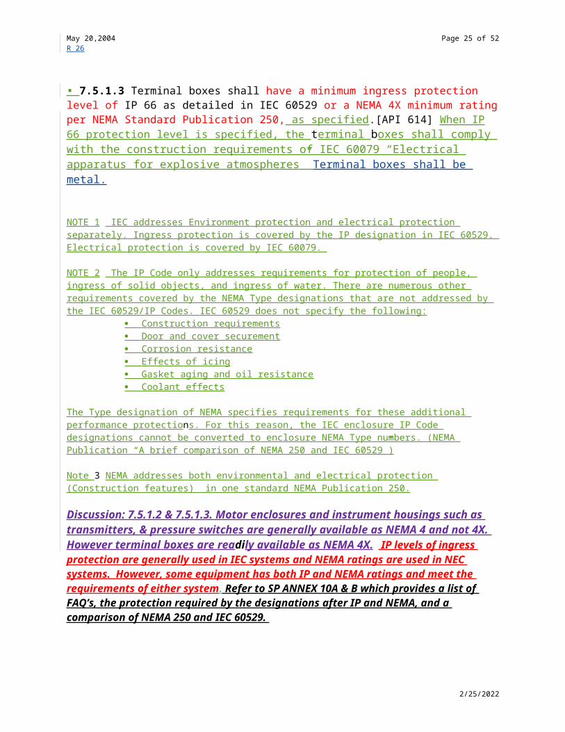
• 7.5.1.3 Terminal boxes shall have a minimum ingress protection level of IP 66 as detailed in IEC 60529 or a NEMA 4X minimum rating per NEMA Standard Publication 250, as specified.[API 614] When IP 66 protection level is specified, the terminal boxes shall comply with the construction requirements of IEC 60079 “Electrical apparatus for explosive atmospheres” Terminal boxes shall be metal.
NOTE 1 IEC addresses Environment protection and electrical protection separately. Ingress protection is covered by the IP designation in IEC 60529. Electrical protection is covered by IEC 60079.
NOTE 2 The IP Code only addresses requirements for protection of people, ingress of solid objects, and ingress of water. There are numerous other requirements covered by the NEMA Type designations that are not addressed by the IEC 60529/IP Codes. IEC 60529 does not specify the following:
Construction requirements Door and cover securement Corrosion resistance Effects of icing Gasket aging and oil resistance Coolant effects
The Type designation of NEMA specifies requirements for these additional performance protections. For this reason, the IEC enclosure IP Code designations cannot be converted to enclosure NEMA Type numbers. (NEMA Publication “A brief comparison of NEMA 250 and IEC 60529”)
5/7/2023

May 20,2004 Page 20 of 38R 26
Note 3 NEMA addresses both environmental and electrical protection (Construction features) in one standard NEMA Publication 250.
Discussion: 7.5.1.2 & 7.5.1.3. Motor enclosures and instrument housings such as transmitters, & pressure switches are generally available as NEMA 4 and not 4X. However terminal boxes are readily available as NEMA 4X. IP levels of ingress protection are generally used in IEC systems and NEMA ratings are used in NEC systems. However, some equipment has both IP and NEMA ratings and meet the requirements of either system . Refer to SP ANNEX 10A & B which provides a list of FAQ’s, the protection required by the designations after IP and NEMA, and a comparison of NEMA 250 and IEC 60529.
7.5.1.4 Instrumentation and Controls shall be designed and manufactured for use in the area classification (class, group, and division or zone) specified in 6.1.11.
7.5.1.5 All conduit, armored cable and supports shall be designed and installed so that it can be easily removed without damage and shall be located so that it does not hamper removal of bearings, seals, or equipment internals.
7.5.1.6 Where applicable, controls and instrumentation shall conform to API RP 551 Part 1 [API 614]
7.5.2 Control Systems
7.5.2.1 The compressor may be controlled on the basis of inlet pressure, discharge pressure, flow, or some combination of these parameters. This may be accomplished by suction throttling, variable inlet guide vanes, speed variation, discharge blowoff (when a constant-speed driver is used), or a cooled bypass from discharge to suction. The control system may be mechanical, pneumatic, hydraulic, electric, or any combination thereof. The system may be manual, or it may be automatic with a manual override. The purchaser shall specify the source of the control signal, its sensitivity and range, and the equipment to be furnished by the vendor.Note to Task Force Chairmen: Modify to address each specific type of equipment.
Discussion: Inlet guide vanes are not normally recommended for use in hydrocarbon service. They have been found to cause problems over time, due to sticking(non functional) and/or prone to leakage of potentially dangerous gases.
7.5.2.2 For a variable-speed drive, the control signal shall act to adjust the set point of the driver's speed-control system. The speed of the machine shall vary linearly and directly with the control signal. Unless otherwise specified, the control range shall be from the maximum continuous speed to 95% of the minimum speed required for any specified operating condition or 70% of the maximum continuous speed, whichever is lower.
7.5.2.3 If specified, a combination of control modes shall be provided.NOTE Typically, this will be necessary on machines with a limited speed range, on multiservice or multistream applications.
Discussion: Example of combination control modes include:
5/7/2023

May 20,2004 Page 21 of 38R 26
a. Plant air compressor-This would be suction throttling in addition to blow offb. Reciprocating compressors-This would be a combination of valve unloading and by-passc. Motor drive is considered a limited range machine
7.5.2.4 The full range of the specified control signal shall correspond to the required operating range of the driven equipment. Unless otherwise specified, the maximum control signal shall correspond to the maximum continuous speed or the maximum flow.
7.5.2.5 Unless otherwise specified, speed shall be adjustable by means of a hand speed changer.
7.5.2.6 Actuation of the control signal or failure of the signal or actuator shall neither prevent the governor from limiting the speed to the maximum permissible nor prevent manual regulation with the hand speed changer.
7.5.2.7 2 If specified, an anti-surge system shall be provided. The scope of supply shall be agreed.The anti surge system shall provide for stable operation, during part load operation during recycle. [617]
7.5.3 Instrument and Control Panels
7.5.3.1 If specified, a panel shall be provided and shall include all panel-mounted instruments for the driven equipment and the driver. Such panels shall be designed and fabricated in accordance with the purchaser’s description. The panel is to be freestanding, located on the base of the unit, or in another location, as specified. The instruments on the panel shall be clearly visible to the operator from the driver control point. If the panel contains lamps a lamp test push button shall be provided. The instruments to be mounted on the panel will be specified.[API 614]
Note to task force Chairmen: Panel-mounted instruments listed on the data sheets may be selected from the following list:a. Pressure gauges: inlet steam, exhaust steam, steam chest, first-stage steam (on multistage turbines), extraction, first stage after extraction section, nozzle bowl (for each valve on automatic multivalve turbines), steam seal, compressor suction, compressor discharge, interstage gas, lube oil, control oil, pump discharge, bearing-oil inlet header.b. Differential pressure gauges: seal oil, oil filter seal gas.c. Temperature gauges: inlet and outlet oil cooler, radial-bearing oil outlet, thrust-bearing oil outlet, compressor suction gas, compressor discharge gas, inlet steam.d. Compressor flowmeter.e. Pump flowmeter.f. Tachometer.g. Ammeter for motor drive.h. Alarms and indicator lights.i. Seal gas flowmeter.
7.5.3.2 Unless otherwise specified, panels shall be made of steel plate at least 3 mm (1/8 in) thick, reinforced, self supporting and closed on the top and sides. If specified, the backs of
5/7/2023

May 20,2004 Page 22 of 38R 26
panels shall be closed to minimize electrical hazards, to prevent tampering or to allow purging for safety or corrosion protection. All instruments shall be flush mounted on the front of the panel and all fasteners shall be of corrosion - resistant material.
Unless otherwise specified, panels shall be made of steel plate at least 3 mm (1/8 in) thick, reinforced, self supporting and closed on the top and sides. The front shall be steel plate at least 3 mm (1/8 in) thick .Tops and sides shall be a minimum of 12 guage in accordance with Table XXX If specified panels shall be totally enclosed to minimize electrical hazards, to prevent tampering or to allow purging for safety or corrosion protection. All instruments shall be flush mounted on the front of the panel and all fasteners shall be of corrosion resistant metal. All interior and exterior surfaces of carbon steel panels shall be prepared and coated with an industrial grade coating system. [API 614 ]
12 Gage Steel Material Thickness (inches)
Uncoated 0.1046Galvanized 0.0934Stainless Steel 0.1094
Table XXX
Discussion: It is not uncommon to have these panels constructed of stainless steel to reduce the life cycle cost.
7.5.3.3 Gauge boards and panels shall be completely assembled, piped and wired, requiring only connection to the purchaser's external piping and wiring circuits.[API 614 ]
7.5.3.4 When more than one wiring point is required on a unit for control or instrumentation, the wiring to each electrical control device or instrument shall be provided from common terminal box (es), with terminal posts. Unless otherwise specified, separate terminal boxes shall be supplied for segration of the AC and DC electrical signals. Each terminal box shall be mounted on the unit, baseplate, or shipped loose as specified. or it's base if any. With purchasers approval one terminal box may be provided if it is provided with an internal barrier that separates the AC and DC wiring.
Discussion: An electrical control device can be a transmitter in addition to a switch. The term electrical control device is more general than switch.
7.5.3.5 In addition to the requirements in 6.2.4.1, additional signal segreation by terminal boxes shall be specified
7.5.3.6. Unless otherwise specified, each terminal box shall be mounted on the unit, or baseplate.
5/7/2023

May 20,2004 Page 23 of 38R 26
NOTE Terminal boxes on some soleplate mounted equipment can result in maintenance access problems. Maintenance access problems can be addressed by shipping terminal boxes loose for field wiring to a nearby location.
7.5.3.7 All leads and posts on terminal strips, switches and instruments shall be tagged for identification. If specified, purchasers tagging shall be applied in addition to the vendors tagging. Wiring inside panels shall be neatly run in wire ducting [API 614 ]
7.5.3.8 Interconnecting piping, tubing or wiring for controls and instrumentation, furnished by the vendor, shall be disassembled only to the extent necessary for shipment.
7.5.4 Instrumentation
7.5.4.1 Tachometers
A tachometer shall be provided if specified for variable speed units. The type, range and indicator provisions shall be as specified. Unless otherwise agreed, the tachometer shall be supplied by the driver vendor and shall be furnished with a minimum range of 0–125% of maximum continuous speed.
7.5.4.2 Temperature Gauges
7.5.4.2.1 Dial type temperature gauges shall be heavy duty and corrosion resistant. They shall be at least 125 mm (5 in) diameter, bimetallic or liquid filled types and, unless otherwise agreed, shall have black marking on a white background.
7.5.4.2.2 The sensing elements of temperature gauges shall be in the flowing fluid.NOTE This is particularly important for lines that can run partially full.
7.5.4.3 Thermowells
Temperature sensing elements shall be furnished with austenitic stainless steel, solid bar, separable thermowells. Unless otherwise specified, the thermowell shall have a 25mm (1 in) process connection. For pressurized lines, this connection shall be flanged. For non pressurized lines, this connection shall be threaded. The thermowell internal connection shall be 13 mm (1/2 in). [API 674]
Discussion: Definition of flammable was eliminated , refer to the discussion after SP 3.9.
Discussion: Internal threaded connections which may become jammed or , it may be possible to unloosen the entire thermowell from the piping.
7.5.4.4 Thermocouples and Resistance Temperature Detectors
Where practical, the design and location of thermocouples and resistance temperature detectors shall permit replacement while the unit is operating. The lead wires of thermocouples
5/7/2023

May 20,2004 Page 24 of 38R 26
and resistance temperature detectors shall be installed as continuous leads between the thermocouple or detector and the terminal box located on the equipment or the baseplate.
7.5.4.5 Pressure Gauges
Pressure gauges (not including built-in instrument air gauges) shall be furnished with AISI Standard Type 316 stainless steel bourdon tubes and stainless steel movements, 110-mm(41/2-in) dials [150-mm (6-in) dials for the range over 55 bar (800 psi)], and NPS 1/2 male alloy steel connections. Black printing on a white background is standard for gauges. If specified, liquid-filled gauges shall be furnished in locations subject to vibration. Gauge ranges shall preferably be selected so that the normal operating pressure is at the middle of the gauge’s range. In no case, however, shall the maximum reading on the dial be less than the applicable relief valve setting plus 10%. Each pressure gauge shall be provided with a device such as a disk insert or blowout back designed to relieve excess case pressure.
7.5.4.6 Vibration and Position Detectors
7.5.4.6.1 Unless otherwise specified, vibration and axial position transducers shall be supplied, installed, and calibrated in accordance with API Standard 670.
7.5.4.6.2 Unless otherwise specified, vibration and axial-position monitors shall be supplied and calibrated in accordance with API Standard 670.Note to FT chairmen: For Special purpose equipment, eliminate “Unless otherwise specified” and mandate Probes and readouts. For GP equipment TF to decide criteria.
7.5.4.6.3 If specified, a bearing-temperature monitor shall be supplied and calibrated in accordance with API Standard 670.
7.5.4.7 Solenoid Valves
7.5.4.7.1 Direct solenoid-operated valves shall be used only in clean, dry instrument-air service, shall have Class F insulation or better, and shall have a continuous service rating. When required for other services, the solenoid shall act as a pilot valve to pneumatic valves, hydraulic operated valves.
Discussion: Solenoid valves are used in clean dry service because of low operating force and may possibly stick if used in dirty service.
7.5.4.8 Pressure Safety (Relief) Valves (PSV) . [API 614 ]
7.5.4.8.1 The vendor shall furnish the relief valves that are to be installed on equipment or piping that the vendor is supplying. Other relief valves related to equipment or piping outside the system that the vendor is supplying, shall be furnished by the purchaser. The vendor's quotation shall list all relief valves and shall clearly state that these valves will be furnished by the vendor.
5/7/2023
May 20,2004 Page 25 of 38R 26
7.5.4.8.2 The sizing, selection and installation of relief valves shall meet the requirements of API Recommended Practice 520, Parts I and II. Relief valves shall be in accordance with API Standard 526. The vendor shall determine the size and set pressure of all relief valves within his scope of supply and recommend the size and setting of relief valves supplied by others required to protect the equipment he supplies. Relief valve sizes and settings shall take into account all possible modes of equipment failure.
7.5.4.8.3 Unless otherwise specified, relief valves shall have steel bodies.
Discussion: This is a generally required safety feature for components subjected to overheating during a fire.
7.5.4.8.4 If specified thermal relief valves shall be provided for accessories or cooling jackets that may be blocked-in by isolation valves.
Discussion: During a blocked in event of a component, heat added can cause fluid expansion resulting in a fire or an explosion. The thermal relief valve relieves when it senses an increase in pressure. [API 619]
7.5.4.9 Flow Indicators
7.5.4.9.1 Flow indicators shall be furnished in the oil-drain return line from each bearing, gear, and seal. Unless otherwise specified flow indicator shall be installed in the outlet piping of each continuously lubricated coupling.
7.5.4.9.2 Unless otherwise specified, the flow indicator shall be:a. Flangedb. Bulls-eye-type with glass on both sidesc. Steel body constructiond. Diameter of not less than one half the inside diameter of the oil pipe.e. Clearly show the minimum oil flow.NOTE -To facilitate viewing of the flow of oil through the line, each flow indicator should be installed with its bullseye-glass in a vertical plane.
Add paragraph on control valves from 614
7.5.4.10 Control Valves (See 614)
7.5.4.11 Add paragraph on differential indicators from 614.
7.5.5 Alarms and Shutdowns
5/7/2023

May 20,2004 Page 26 of 38R 26
7.5.5.1 An alarm/shutdown system shall be provided which will initiate an alarm if any one of the specified parameters reaches an alarm point and will initiate shutdown of the equipment if any one of the specified parameters reaches the shutdown point.
7.5.5.2 The purchaser shall specify the alarms and trips required which, as a minimum, should include those listed in Table 2.Note to Task Force Chairmen: Insert Table here.
7.5.5.3 The Vendor shall advise the purchaser of any additional alarms and/or shutdowns considered essential to safeguard the equipment.
7.5.5.4 The purchaser shall specify the extent to which this alarm/shutdown system is to be supplied by the equipment vendor. This can conveniently be achieved by the use of a responsibility matrix.Note: Refer to API Std 614 (Appendix C, Chapter I) for a typical responsibility matrix chart). 614 deleted this matrix because nobody used it.
7.5.5.5 Unless otherwise specified, the alarm/shutdown system shall comply with the requirements of 7.5.5.5.1 through 7.5.5.5.8NOTE It is accepted that with some systems, particularly those based on conventional direct acting instruments, complete compliance with the requirements of 7.5.5.5.1 through 7.5.5.5.8 may not be achievable. Examples of alarm/shutdown system arrangements generally considered acceptable, are given in Appendix XXX.
7.5.5.5.1 For every shutdown parameter an alarm shall be provided with the alarm point set at a lesser deviation from the normal condition than the associated shutdown point.
7.5.5.5.2 Any alarm parameter, reaching the alarm point, shall initiate an audible warning or flashing light or both as specified. It shall be possible to determine which parameter initiated the alarm.
7.5.5.5.3 Any shutdown parameter, reaching the shutdown point, shall cause the equipment to shutdown and shall initiate an audible warning or a flashing light or both as specified which shall be distinguishable from those associated with an alarm. It shall be possible to determine which parameter initiated the shutdown.
7.5.5.5.4 When any component of the alarm/shutdown system malfunctions, an alarm shall be initiated and shall be distinguishable from alarms resulting from malfunction of the equipment. To accomplish this redundant sensors may be required.
7.5.5.5.5 When any malfunction of a component of the shutdown system results in the system being unable to recognize a shutdown condition, the equipment shall automatically shutdown and an alarm shall be initiated. This alarm shall be distinguishable from shutdowns resulting from malfunction of the equipment(fail-safe system). When a non-fail-safe system is specified, a failure that results in the system being unable to recognize a shutdown condition shall also result in all other shutdown and alarms remaining functional
5/7/2023

May 20,2004 Page 27 of 38R 26
7.5.5.5.6 When a non-fail safe system is specified, a failure that results in the system being unable to recognize an alarm condition shall also result in all other alarms and shutdowns remaining functional.
7.5.5.5.7 It shall be possible to test every component of every alarm function while the equipment is in operation. Such testing shall not require the disarming of any shutdown function.
7.5.5.5.8 With the exception of the final shutdown device (circuit breaker, steam trip and throttle valve, fuel valve, etc.),it shall be possible to test every component of every shutdown function while the equipment is in operation. The testing of components associated with a shutdown function shall not require disarming of any other shutdown function nor any alarm function.NOTE This allows all alarms to be bypassed during testing of switches.
7.5.5.6 If specified, the alarm/shutdown system shall incorporate a first-out annunciator facility to indicate which parameter first reached the alarm level and which parameter first reached the shutdown level, in the event that multiple alarms and/or shutdown result from a single initial event. Where this facility is not incorporated as part of an integrated control and monitoring system, a separate annunciator instrument shall be provided (See 7.5.5.9).
7.5.5.7 If specified, the alarm/shutdown system shall incorporate an event recorder to record the order of occurrence of alarms and shutdowns. Time resolution shall be not greater than 100 milliseconds.[API 614 ].
NOTE The special event recorder normally associated with a DCS may not have a sufficiently fast scanning rate.
7.5.5.8 Unless otherwise specified, the necessary valving and switches or bridging links (Jumpers) or other approved protocol shall be provided to enable all instruments and other components, except shutdown sensing devices, to be replaced with the equipment in operation. . [API 614 ]
7.5.5.9 If specified, shutdown sensing devices shall be provided with valving, bridging links or other approved protocol to allow replacement with the equipment in operation. Isolation valves for shutdown sensing devices shall be provided with means of locking the valves in the open position.[API 614 ]
7.5.5.9 Annunciator
7.5.5.9.1 If a first-out annunciator feature has been specified in 7.5.5.6 , whether as a separate instrument or incorporated into an integrated control and monitoring facility, the sequence of operation shall be as follows:a. The first parameter to reach alarm or shutdown shall cause the flashing of a light and the sounding of an audible device.b. The alarm or shutdown condition shall be acknowledged by operating an alarm silencing button, common to all alarms and shutdowns.
5/7/2023

May 20,2004 Page 28 of 38R 26
c. When the alarm or shutdown is acknowledged, the audible device shall be silenced but the light shall remain steadily lit as long as that alarm or shutdown condition exists.d. If another parameter reaches an alarm or shutdown level the light shall return to the flashing condition and the audible device shall sound, even if the previous alarm/shutdown condition has been acknowledged but still exists.
Discussion: ISA 18.1 Annunciator Sequence and Specifications was reviewed by the 614 TF and it was decided not to reference this document. ISA 18.1 describes annunciator sequences and does not default to any one sequence. It is not a specification that describes the component details of an annuniator. Since the functions of an annunciator have been specified in 7.5.5.9 referencing ISA 18.1 has not been included.
7.5.5.9.2 If the first-out annunciator feature is provided by a separate instrument, this shall be mounted on a local panel. There shall be approximately 25% spare points and separate connections shall be provided for remote indication if any alarm operates or any shutdown operates.
7.5.5.10 Alarm and Trip Switches
Where alarm and/or shutdown functions are initiated by locally mounted switches, such switches shall comply with 7.5.5.10.1 through 7.5.5.10.9
7.5.5.10.1 Each alarm switch and each shutdown switch, except as noted in 7.5.5.10.7 and 7.5.5.10.8 shall be furnished in a separate housing located to facilitate inspection and maintenance.
Discussion: For extreme adverse corrosive environment non metal housings may be required.
7.5.5.10.2 Hermetically sealed, single pole, double throw switches with a minimum capacity of 5 amperes at 120 volts AC and 0.5 ampere at 120 volts DC shall be provided. Mercury switches shall not be used.
7.5.5.10.3 The purchaser shall specify whether switches shall be connected to open (deenergize) or close (energize) to initiate alarms and shutdowns.
Discussion: Switches connected to open (deenergize) are normally considered to be fail safe. However, 7.5.5.10.3 allows the purchaser to make decisions based on possible combinations which may be available.
7.5.5.10.4 Alarm and trip switches shall not be adjustable from outside the housing.
7.5.5.10.5 Housings for alarm and shutdown switches shall comply with the requirements of 7.5.6.2
5/7/2023

May 20,2004 Page 29 of 38R 26
7.5.5.10.6 The sensing elements of pressure switches shall be of stainless steel (AISI Standard Type 300 stainless steel). Low pressure switches ,which are actuated by falling pressure, shall be equipped with a pressure gage, valved bleed or vent connection to allow controlled depressurizing during testing. High pressure switches which are activated by rising pressure, shall be equipped with a valved test connection so that a portable pump can be used to raise the pressure during testing. The arrangement to be used shall be specified by the purchaser. Typical arrangements are described in Appendix X.X.X.
Discussion: The pressure gage described does not have to be permanently installed.
7.5.5.10.7 Temperatures shall be measured by thermocouples or resistance temperature detectors as specified and shall be connected to local panel mounted instruments. Multipoint instruments may be used except that alarms and shutdowns shall be connected to separate instruments and separate alarm or shutdown contacts(switches) shall be provided for each temperature monitored. Each alarm and shutdown level shall be separately adjustable.
7.5.5.10.8 Vibration and/or axial position switches shall be provided by instruments complying with the requirements API 670 (see 3.5.4.6).
7.5.5.10.9 Level switches shall be of the float or displacer type mounted in separate enclosures which can be isolated from the associated vessel. Level switches shall be capable of testing with out shutting down the equipment or removing the vessel or reservoir from service. Valved test connections shall be provided to enable the level to be artificially raised or lowered as necessary to test the function of the switch or a top mounted switch can be provided on atmospheric vessels such as oil reservoirs.
7.5.6 Electrical Systems
7.5.6.1 Motors, heaters and instrumentation shall be suitable for the power supplies specified. A pilot light shall be provided on the incoming side of each supply to indicate that the circuit is energized. The pilot lights shall be installed on the control panel.
7.5.6.2 Electrical equipment located on the unit or on any separate panel shall conform to the electrical area classification specified. Electrical starting and supervisory controls may be either AC or DC.
Discussion: Requirements may differ, depending on whether a “division” or “zone” electrical area classification is specified. For additional information regarding area classification refer to the IEC 79 (National Electric Code)
7.5.6.3 Power and control wiring, located on, adjacent to, or connected to the equipment, shall be resistant to oil, heat, moisture and abrasion. Stranded conductors shall be used when connected to or located on machinery or in other areas subject to vibration. Measurement and remote control panel wiring may be solid conductor. The insulation shall be flame retardant, moisture and heat resistant thermoplastic, and when necessary for abrasion resistance shall be
5/7/2023

May 20,2004 Page 30 of 38R 26
provided with an outer covering. Wiring shall be suitable for the local temperatures to be encountered.
Discussion: Stranded wire is normally used to avoid failure due to fatigue in areas subject to vibration. Solid wire may be used in areas not subject to vibration.
Discussion: Refer to NEC Article 310 for a description of insulation and types of sheathing.
7.5.6.4 All leads on terminal strips, switches, and instruments shall be permanently tagged for identification. All terminal boards in junction boxes and control panels shall have at least 20% spare terminal points.
7.5.6.5 To guard against accidental contact, enclosures shall be provided for all terminal strips, relays, switches and other energized parts. Electrical power wiring shall be segregated from instrument and control signal wiring both externally and, as far as possible, inside enclosures. Inside enclosures which may be required to be opened with the equipment in operation, for example, for alarm testing or adjustment, shall be provided with secondary shields or covers for all terminal strips and other exposed parts carrying electrical potential in excess of 50 volts. Maintenance access space shall be provided around or adjacent to electrical equipment or in accordance with the appropriate code such as the National Electrical Code, Article 110. or other internationally recognized standard as approved by the purchaser.
Discussion: The 50 volt components inside a panel are meant to be in a secondary enclosure.
7.5.6.6 Electrical materials including insulation shall be corrosion resistant and nonhygroscopic insofar as is possible. If specified for tropical location, materials shall be given the treatments specified in 7.5.6.6.1 and 7.5.6.6.2.
7.5.6.6.1 Parts (such as coils and windings) shall be protected from fungus attack.
7.5.6.6.2 Unpainted surfaces shall be protected from corrosion by plating or another suitable coating.
7.5.6.7 Control, instrumentation and power wiring, that is not within a fully enclosed panel or other enclosure, shall be in the form of armoured cable or shall be run in metal conduit as specified. Cables shall be supported on cable trays supported to prevent damage from pedestrian traffic. Conduit shall be properly supported to avoid damage caused by vibration and isolated and shielded to prevent interference between different services. Conduits may terminate (in the case of the leads to temperature elements, shall terminate) with a length of flexible metal conduit, long enough to facilitate maintenance without removal of the conduit. In applications where conduit temperatures are above 60 °C, (140 °F) the flexible conduit shall be 19 mm bronze hose with four-wall-interlocking construction and joints with packed-on heatproof couplings shall be used.[616]
5/7/2023

May 20,2004 Page 31 of 38R 26
7.5.6.8 For Division 2 locations, flexible metallic conduits shall have a liquid tight thermosetting or thermoplastic outer jacket and approved fittings. For Division 1 locations, an NFPA-approved connector shall be provided. 614 consider removing 2ed sentence since its covered in SP 6.1.11.
Discussion. For division 2 non jacketed flexible cable (BX Cable) can be provided. 7.5.6.8 requires a liquid tight, thermoplastic outer jacket.
7.5.6.9 AC and DC circuits shall be clearly labeled, connected to separate terminal blocks, and isolated from each other.
7.5.6.10 Conduit drains shall be installed in all conduit low points for outdoor installations. [API 614 ]
7.5.6.11 If specified for indoor installations conduit drains shall be installed in all conduit low points for outdoor installations.[API 614 ]
7.6 PIPING
7.6.1 General
7.6.1.1 Piping design, joint fabrication, examination and inspection shall be in accordance with ASME B 31.3. . Welding of piping shall be performed in accordance with 6.11.4.1
Discussion: Wording removed since welding of piping is covered in 6.11.4.1and there is no need to restate in 7.6.1.1.
7.6.1.2 Auxiliary systems are piping systems that include the following services:
Group I1. Sealing fluid.2. Gland and flushing fluid.3. Recirculation fluid.4. Balance gas.5. Buffer gas.6. Fuel gas or oil.7. Starting gas.8. Process-side drains and vents.9. Solvent injection.
Group II1. Sealing steam.2. Steam injection.3. Water injection.4. Starting air.
5/7/2023

May 20,2004 Page 32 of 38R 26
5. Instrument and control air.6. Drains and vents associated with above systems.
Group III1. Cooling water.2. Liquid wash(water based).3. Drains and vents associated with above systems.
Group IV1. Lubricating oil.2. Control oil.3. Oil-system drains and vents.
NOTE - Casing connections are discussed in 6.4.
Note to Task Force Chairmen: Select the appropriate services for the specific Standard being addressed.
7.6.1.3 Piping systems shall include piping, tubing where permitted, isolating valves, control valves, relief valves, pressure reducers, orifices, temperature gauges and thermowells, pressure gauges, sight flow indicators, and all related vents and drains.
7.6.1.4 The vendor shall furnish all piping systems, including mounted appurtenances, located within the confines of the main unit’s base area, any oil console base area, or any auxiliary base area. The piping shall terminate with flanged connections at the edge of the base. When soleplates are specified for the equipment train, the extent of the piping system at the equipment train shall be defined by the purchaser. The purchaser shall furnish only interconnecting piping between equipment groupings and off-base facilities. [7.6.3.2]
7.6.1.5 The design of piping systems shall achieve the following:a. Proper support and protection to prevent damage from vibration or from shipment, operation and maintenance.b. Proper flexibility and adequate accessibility for operation, maintenance and thorough cleaning.c. Installation in a neat and orderly arrangement adapted to the contours of the equipment without obstructing access areas.d. Elimination of air pockets by the use of valved vents or the use of non-accumulating piping arrangements.e. Complete drainage through low points without disassembly of piping.
7.6.1.6 Piping shall preferably be fabricated by bending and welding to minimize the use of flanges and fittings. Flanges are permitted only at equipment connections, at the edge of any base and for ease of maintenance. The use of flanges at other points is permitted only with the purchaser's specific approval. Other than tees and reducers, welded fittings are permitted only to facilitate pipe layout in congested areas. Threaded connections shall not be used except (withthe purchaser's approval) where essential for space or access reasons. Pipe bushings shall notbe used.
5/7/2023

May 20,2004 Page 33 of 38R 26
Discussion: Pipe bushings are not allowed since they can be thin walled and may crack.
7.6.1.7 Pipe threads, where permitted, shall be taper threads in accordance with ISO 7-1 or ASME B.1.20.1 as specified . If ISO 7 Part 1 has been specified, tapered or straight internal threads shall also be specified. Flanges shall be steel and in accordance with ISO 7005-1 6.4.11. Slip-on flanges are permitted only with the purchaser's specific approval. For socket-welded construction, a 2 mm (1/16 in.) gap shall be left between the pipe end and the bottom of the socket.
Discussion: Refer to 3.37 and 6.4.8 for the discussion of ASME B 1.20.1 and US tapered pipe threads.
ISO 7-1 specifies the requirements for thread form for joints made pressure-tight by the mating of the threads. These threads are taper external, parallel internal or taper internal. Threads are designated by the term Pipe thread ISO 7 followed by a letter(s) symbol representing the type of thread and then the thread size. The following is provided to illustrate the nomenclature for a right handed thread size 1 ½ .
Internal thread Parallel Pipe thread ISO 7-Rp 1 1/2Taper Pipe thread ISO 7-Rc 1 1/2
External thread
Always taper Pipe thread ISO 7-R 1 1/2
The thread size is obtained from column 1 table 1 of ISO 7-1
The term “taper threads” in 7.6.1.7 requires that both the external and internal threads be tapered and eliminates the option for external straight threads as allowed by ISO 7-1. The reference to ISO 7005-1 was replaced by paragraph 6.4.11 since 6.4.11 covers ANSI and ISO flanges.
The reference to ISO 7005-1 was replaced by paragraph 6.4.11 since 6.4.11 covers ANSI and ISO flanges.
7.6.1.8 Connections, piping, valves, and fittings that are 32 mm (11/4 in), 65 mm (21/2 in),90 mm (31/2 in), 125 mm (5 in), 175 mm (7 in), or 225 mm (9 in) in size shall not be used.
7.6.1.9 Where space does not permit the use of NPS 1/2, 3/4, OR 1 pipe, seamless tubing may be furnished in accordance with Table 3.
7.6.1.10 The minimum size of any connection shall be NPS ___.
7.6.1.11 Piping systems furnished by the vendor shall be fabricated, installed in the shop, and properly supported. Bolt holes for flanged connections shall straddle lines parallel to the main horizontal or vertical centerline of the equipment.
5/7/2023

May 20,2004 Page 34 of 38R 26
7.6.1.12 Pipe plugs shall be in accordance with 6.4.5
7.6.2 Oil Piping
7.6.2.1 Gravity return lines shall be sized to run no more than half full when flowing at a velocity of 0.3 m/s and shall be arranged to ensure good drainage (recognizing the possibility of foaming conditions). Gravity return lines shall have a downward slope towards the reservoir of not less than 4%. If possible, lateral branches (not more than one in any transverse plane) should enter drain headers at approximately 45° angles in the direction of flow.
Table 3—Minimum Requirements for Piping System Components [API 619]Steam Cooling Water Lube Oil
System
≤75 pounds per square inch
gauge
>75 pounds per square inch
gaugeStandard(≤NPS 1) Optional ≤NPS 1 ≥NPS 11/2
Pipe Seamlessa Seamlessa ASTM A 53 Type F Schedule 40, galvanized to ASTM A 153
ASTM A 312, Type 304 or 316 stainless steelb
Tubing ASTM A 269, seamless Type 304 or 316 stainless steelc
ASTM A 269, seamless Type 304 or 316 stainless steelc
ASTM A 269, seamless Type 304 or 316 stainless steelc
All Valves Carbon steel, Class 800
Carbon steel, Class 800
Bronze,Class 200
Bronze,Class 200
Carbon steel, Class 800
Carbon steel, Class 800
Gate and Globe Valves
Bolted bonnet and gland
Bolted bonnet and gland
Bolted bonnet and gland
Bolted bonnet and gland
Pipe Fittings and Unions
Forged,Class 3 000
Forged,Class 3 000
ASTM A 338 and A 197, Class 150 malleable iron, galvanized to ASTM A 153
ASTM A 338 and A 197, Class 150 malleable iron, galvanized to ASTM A 153
Stainless steel Stainless steel
Tube Fittings Carbon steel, compression, manufacturer’s standard
Manufacturer’s standard
Carbon steel, compression, manufacturer’s standard
Fabricated joints ≤11/2 inches
Threaded Socket welded Threaded Threaded Carbon steel slip-on flange
Fabricated joints≥2 inches
Slip-on flange Socket-weld or weld-neck flange
Purchaser shall specify
Purchaser shall specify
Carbon steel slip-on flange
Gaskets Type 304 or 316 stainless steel, spiral wound, or iron or soft steel
Type 304 or 316 stainless steel, spiral wound, or iron or soft steel
Type 304 or 316 stainless steel, spiral wound
Flange bolting ASTM A 193, Grade B7 ASTM A 194, Grade 2H
ASTM A 193, Grade B7 ASTM A 194, Grade 2H
ASTM A 193, Grade B7 ASTM A 194, Grade 2H
5/7/2023
May 20,2004 Page 35 of 38R 26
NOTE - Carbon steel piping shall conform to ASTM A 106, Grade B; ASTM A 524; or API Specification 5L, Grade A or B. Carbon steel fittings, valves, and flanged components shall conform to ASTM A 105 and A 181. Stainless steel piping shall conform to ASTM A 312.
aSchedule 80 for diameters from 1/2 inch to 11/2 inches; Schedule 40 for diameters 2 inches and larger.bSchedule 40 for a diameter of 11/2 inches; Schedule 10 for diameters of 2 inches and larger.c1/2-inch diameter 0.065-inch wall, 3/4-inch diameter 0.095-inch wall, or 1-inch diameter 0.109-inch wall.
7.6.2.2 Nonconsumable backup rings and sleeve-type joints shall not be used. Pressure piping downstream of oil filters shall be free from internal obstructions that could accumulate dirt. Socket-welded fittings shall not be used in pressure piping downstream of oil filters. (Table 3)
7.6.2.3 Unless otherwise specified, oil-supply piping and tubing, including fittings (excluding slip-on flanges), shall be stainless steel. (Table 3)
Discussion: St Steel eliminates potential for scale build-up in piping
7.6.2.4 Provision shall be made for bypassing the bearings (and seals if applicable) of equipment during oil system flushing operations.
Discussion: Prevents dirt from accumulating in the bearing.
7.6.3 Instrument Piping
7.6.3.1 The vendor shall supply all necessary piping, valves, and fittings for instruments and instrument panels (see 7.5.3.2).
7.6.3.2 Initial connections for pressure instruments and test points shall comprise a branch and isolation valve to the same standard as the system to which it is connected. Beyond the initial isolation valve, piping or tubing not less than 10 mm outside diameter may be used. Where convenient, a common connection may be used for remotely mounted instruments that measure the same pressure. Such common connections shall not be smaller than DN 15 (NPS ½) and separate secondary isolation valves shall be provided for each instrument. Where a pressure gauge is to be used for testing pressure alarm or shutdown switches, common connections are required for the pressure gauge and the associated switches.
7.6.4 Process Piping
7.6.4.1 The extent of and requirements for process piping to be supplied by the vendor will be specified.
7.6.4.2 The requirements of 7.6.1 shall apply to process piping supplied by the vendor.
7.6.4.3 If specified the vendor shall review the design of all piping, appurtenances, and vessels (e.g. pulsation suppression devices, intercoolers, aftercoolers, knockouts, air intake filters and expansion joints) and supports immediately upstream and downstream of the equipment. The purchaser and the vendor shall agree on the scope of this review.
7.6.5 Intercoolers and Aftercoolers
5/7/2023
May 20,2004 Page 36 of 38R 26
7.6.5.1 If specified, the vendor shall furnish a water-cooled shell-and-tube intercooler between each compression stage.
7.6.5.2 Intercoolers shall be air cooled or water cooled as specified.
7.6.5.3 The purchaser shall specify if aftercoolers are to be furnished by the vendor.
7.6.5.4 Intercoolers and aftercoolers shall be furnished in accordance with Section VIII,Division 1, of the ASME Code or other purchaser specified pressure design code.
7.6.5.5 Water-cooled shell-and-tube intercoolers and aftercoolers shall be designed and constructed in accordance with TEMA Class C or R, as specified. . When TEMA Class R has been specified, the heat exchanger shall be in accordance with API Standard 660.NOTE - Caution should be exercised regarding the susceptibility of heat exchangers and their supporting structures to pulsation-induced vibration.
7.6.5.6 Unless otherwise approved by the purchaser, intercoolers and aftercoolers shall be constructed and arranged to allow removal of tube bundles without dismantling piping or compressor components. Water shall be on the tube side.
7.6.5.7 Fixed-tube-sheet exchangers shall have inspection openings into their gas passages. Rupture disks on the shell side (to protect the shell in case of tube failures) shall be used only when specifically approved by the purchaser.
7.6.5.8 When air coolers are specified, they shall be in accordance with API Standard 661.
7.6.5.9 Unless otherwise specified, air-cooled heat exchangers used for intercoolers shall have automatic temperature control. This control may be accomplished by means of louvers, variable-speed fans, variable-pitch fans, bypass valves, or any combination of these. Proposed control systems shall be approved by the purchaser.
7.6.5.10 If specified, water-cooled double-pipe intercoolers and aftercoolers shall be furnished. A finned double-pipe design may be furnished only when specifically approved by the purchaser.[API 614]
7.6.5.11 Intercoolers shall be either machine mounted or separately mounted, as specified.
Discussion: Machine mounted intercoolers are sometimes installed on reciprocating compressors.
7.6.5.12 Materials of construction shall be those specified.
7.6.5.13 When condensate separation and collection facilities are furnished by the vendor, they shall include the following:a. An automatic drain trap with a manual bypass.
5/7/2023

May 20,2004 Page 37 of 38R 26
b. An armored gauge glass with isolation valves and blowdown valves on the collection pot.c. Separate connections and level switches for high-level alarm and trip on the collection pot.d. Collection pots sized to provide an agreed-upon holding capacity and a 5-minute time span between high-level alarm and trip, based on the expected normal liquid condensate rate.e. Separate connections and level switches for the high-level alarm and trip on the collection pot.
7.6.5.14 If specified, the vendor shall furnish the fabricated piping between the compressor stages (or the nozzles of centrifugal compressor bodies) and the intercoolers and aftercoolers. Interstage piping shall conform to ASME B31.3.
Discussion: Because of pressure drop considerations, vendor would have to know exact location of equipment
7.7 SPECIAL TOOLS
7.7.1 When special tools or fixtures are required to disassemble, assemble or maintain the equipment, they shall be included in the quotation and furnished as part of the initial supply of the equipment. For multiple-unit installations, the requirements for quantities of special tools and fixtures shall be agreed between purchaser and vendor. These special tools shall be used, and their use demonstrated, during shop assembly and post test disassembly of the equipment.
7.7.2 When special tools are provided, they shall be packaged in a separate, rugged metal box or boxes and shall be marked “special tools for (tag/item number).” Each tool shall be stamped or metal tagged to indicate its intended use.
7.8 Coatings, Insulation, and Jacketing• 7.8.1 If specified, surfaces shall be treated to prevent under insulation corrosion.
Note: This is especially important for materials which are subject to chloride stress corrosion cracking such as Austenetic Stainless Steels (300 Series) when exposed to external environments which contain chlorides such as spray from sea water or cooling towers.
Discussion: Insulation can be a source of chlorides and/or cause the retention of water and chloride concentrating under the insulation. Chloride stress corrosion cracking 9Cl-SCC) can be caused by the spray from sea water and cooling water towers carried by the prevailing winds. The spray soaks the insulation over the austenitic stainless steel equipment/piping, the chloride concentrates by evaporation, and cracking occurs in the areas with residual stresses. Other cases of cracking under insulation have resulted from water dripping on insulated pipe and leaching chlorides from insulation. Mitigation of Cl-SCC under insulation is best accomplished by preventing chloride accumulation on the stainless steel surface. This is best accomplished by first maintaining the integrity of the insulation. Second, by preventing chloride ions from contacting the stainless steel surface with a protective coating.
5/7/2023

May 20,2004 Page 38 of 38R 26
Refer to SP Informative Annex 14 for additional information on chloride stress corrosion cracking and under insulation Chloride stress corrosion cracking.
7.9 Starting Equipment7.10 Fuel System
5/7/2023
Related Documents


![The Opening Lings.pdf · 3 whosoever shall follow My guidance, no fear shall come upon them, neither shall they grieve. [BC]](https://static.cupdf.com/doc/110x72/5e69df3ddd5a2d331622d21c/the-opening-lingspdf-3-whosoever-shall-follow-my-guidance-no-fear-shall-come.jpg)


![mattredman.com · 2019-11-25 · We shall not be shaken. [to Verse] Mid section: We shall, we shall not be shaken. Bb2(G2) We shall, we shall not be shaken When all around is sinking](https://static.cupdf.com/doc/110x72/5ee33d8bad6a402d666d3d47/2019-11-25-we-shall-not-be-shaken-to-verse-mid-section-we-shall-we-shall.jpg)
![mattredman.commattredman.com/wp-content/uploads/2017/10/WeShallNotBeShaken.pdfWe shall not be shaken. [to Verse] Mid section: We shall, we shall not be shaken. Bb2(G2) We shall, we](https://static.cupdf.com/doc/110x72/5edc1134ad6a402d666693a0/we-shall-not-be-shaken-to-verse-mid-section-we-shall-we-shall-not-be-shaken.jpg)
