Nuclear Operating Company South Texas Protect £1ectric Generating Station PHO. Box 289 Wadsworth, TeXas 77483 •/j _ February 17, 2016 N OC-AE- 15003311 10 CER 2.202 U. S. Nuclear Regulatory Commission Attention: Document Control Desk Washington, DC 20555-0001 South Texas Project Units 1 & 2 Docket No. STN 50-498, STN 50-499 Notification of Full Compliance with Order EA-12-049 for Mitigation Strategies for Beyond Design Basis External Events and Update for Order EA-12-051 for Reliable Spent Fuel Pool Instrumentation References: 1. NRC Order Number EA-12-049, "Issuance of Order to Modify Licenses with Regard to Requirements for Mitigation Strategies for Beyond-Design-Basis External Events", March 12, 2012 (AE-NOC-1 2002268)(ML1 2073A1 95) 2. Letter from G.T. Powell, STPNOC, to NRC Document Control Desk, "Notification of Compliance with Orders EA-12-049 for Mitigation Strategies for Beyond-Design Basis External Events and EA-12-051 for Reliable Spent Fuel Pool Instrumentation (TAC Nos. MF0826 and MF0828)", July 2, 2015 (NOC-AE-15003257)(ML15196A031) 3. Letter from D.L. Koehl, STPNOC, to NRC Document Control Desk, "STPNOC Overall Integrated Plan in Response to March 12, 2012 Commission Order Modifying Licenses with Regard to Requirements for Mitigation Strategies for Beyond-Design- Basis External Events (Order Number EA-12-049)", February 28, 2013 (NOC-AE-1 3002963) (ML1 3070A01 1) 4. Letter from J.S. Bowen, NRC, to D.L. Koehl, STPNOC, "Interim Staff Evaluation Relating to Overall Integrated Plan in Response to Order EA-1 2-049 (Mitigation Strategies) (TAC Nos. MF0825 and MF0826)", January 29, 2014 (AE-NOC- I14002494)(M L 13339A736) 5. Letter from T. Brown, NRC, to D.L. Koehl, STPNOC, "South Texas Project, Units 1 and 2 - Report for the Onsite Audit Regarding Implementation of Mitigating Strategies and Reliable Spent Fuel Instrumentation Related to Orders EA-12-049 and EA-12-051 (TAC Nos. MF0825, MF0826, MF0827, and MF0828)", May 6, 2015 (AE-NOC-1 5002661) (ML1 511 1A465) 6. Letter from G.T. Powell, STPNOC, to NRC Document Control Desk, "Report of Full Compliance with Order EA-12-051 Reliable Spent Fuel Pool Instrumentation," January 19, 2016 (NOC-AE-15003297) STI 34239725

Welcome message from author
This document is posted to help you gain knowledge. Please leave a comment to let me know what you think about it! Share it to your friends and learn new things together.
Transcript
Nuclear Operating Company
South Texas Protect £1ectric Generating Station PHO. Box 289 Wadsworth, TeXas 77483 •/j _
February 17, 2016N OC-AE- 1500331110 CER 2.202
U. S. Nuclear Regulatory CommissionAttention: Document Control DeskWashington, DC 20555-0001
South Texas ProjectUnits 1 & 2
Docket No. STN 50-498, STN 50-499Notification of Full Compliance with Order EA-12-049 for
Mitigation Strategies for Beyond Design Basis External Events andUpdate for Order EA-12-051 for Reliable Spent Fuel Pool Instrumentation
References:
1. NRC Order Number EA-12-049, "Issuance of Order to Modify Licenses with Regard toRequirements for Mitigation Strategies for Beyond-Design-Basis External Events",March 12, 2012 (AE-NOC-1 2002268)(ML1 2073A1 95)
2. Letter from G.T. Powell, STPNOC, to NRC Document Control Desk, "Notification ofCompliance with Orders EA-12-049 for Mitigation Strategies for Beyond-Design BasisExternal Events and EA-12-051 for Reliable Spent Fuel Pool Instrumentation (TACNos. MF0826 and MF0828)", July 2, 2015 (NOC-AE-15003257)(ML15196A031)
3. Letter from D.L. Koehl, STPNOC, to NRC Document Control Desk, "STPNOCOverall Integrated Plan in Response to March 12, 2012 Commission Order ModifyingLicenses with Regard to Requirements for Mitigation Strategies for Beyond-Design-Basis External Events (Order Number EA-12-049)", February 28, 2013(NOC-AE-1 3002963) (ML1 3070A01 1)
4. Letter from J.S. Bowen, NRC, to D.L. Koehl, STPNOC, "Interim Staff EvaluationRelating to Overall Integrated Plan in Response to Order EA-1 2-049 (MitigationStrategies) (TAC Nos. MF0825 and MF0826)", January 29, 2014 (AE-NOC-I14002494)(M L 13339A736)
5. Letter from T. Brown, NRC, to D.L. Koehl, STPNOC, "South Texas Project, Units 1and 2 - Report for the Onsite Audit Regarding Implementation of MitigatingStrategies and Reliable Spent Fuel Instrumentation Related to Orders EA-12-049and EA-12-051 (TAC Nos. MF0825, MF0826, MF0827, and MF0828)", May 6, 2015(AE-NOC-1 5002661) (ML1 511 1A465)
6. Letter from G.T. Powell, STPNOC, to NRC Document Control Desk, "Report of FullCompliance with Order EA-12-051 Reliable Spent Fuel Pool Instrumentation,"January 19, 2016 (NOC-AE-15003297)
STI 34239725
N OC-AE- 15003311Page 2 of 4
The purpose of this letter is to fulfil the requirement to report to the NRC that STP Unit 1 andUnit 2 are in full compliance with Order EA-12-049 (Reference 1) regarding mitigation strategiesfor Beyond-Design-Basis External Events. Notification for STP Unit 2 compliance isdocumented in a previous submittal (Reference 2).
Section IV.A.2 of Order EA-1 2-049 requires full implementation no later than two refuelingcycles after submittal of the Overall Integrated Plan (Reference 3) or December 31, 2016,whichever comes first. In addition, Section IV.C.3 of Order EA-12-049 requires that licenseesreport to the NRC when full compliance is achieved. On December 19, 2015, STP Unit 1entered Mode 2 (Startup). STP Unit 1 and Unit 2 were in full compliance with both Order EA-12-049 and EA-12-051 at that time. Reference 6 submitted the report of full compliance for OrderEA-12-051.
The Enclosure for this letter provides a brief summary of the key elements associated withcompliance with Order EA-12-049 including a completed milestone accomplishment schedule.
Attachment 1 includes summary responses for the open and confirmatory items from the NRC'sInterim Staff Evaluation (ISE) of STP's Overall Integrated Plan (Reference 4). The informationcontained in Attachment 1 is considered legacy information and may not accurately reflect thecurrent diverse and flexible coping (FLEX) strategies. The current STP FLEX strategies aredescribed in the Final Integrated Plan (FIP) (Attachment 4).
Attachment 2 provides a clarification related to the response to open and pending itemsdocumented in the Onsite Audit Report (Reference 5) that were provided with the STP Unit 2Order compliance letter (Reference 2).
Attachment 3 provides responses to other NRC questions that arose after the Audit Report wasissued. STPNOC considers the response items listed in Attachments 1 through-3 completepending NRC closure.
Attachment 4 to this letter is the STP FLEX Final Integrated Plan (FIP) that includes a summaryof FLEX strategies, descriptions of FLEX equipment and descriptions of applicable hazards.
NOC-AE- 15003311Page 3 of 4
There are no regulatory commitments in this letter.
If there are any questions, please contact Wendy Brost at (361) 972-8516 or me at(361) 972-7566.
I declare under penalty of perjury that the foregoing is true and correct.
Executed on: f'¢nvi 171 o'/•
G. T. PowellSite Vice President
web
Enclosure:
Attachments:
Summary of Compliance with NRC Order EA-12-049 Regarding MitigationStrategies for Beyond-Design-Basis External Events and Update of ComplianceDate for Order EA-12-051 Regarding Reliable Spent Fuel Pool Instrumentation
1. Summary of Responses for the FLEX Interim Staff Evaluation Open andConfirmatory Items
2. Update to Response to Open and Pending Items from the FLEX and SFPLIAudit Report
3. Summary of Reponses for Other Issues that Arose after the Audit Report4. STP FLEX Final Integrated Plan (FIP)
N OC-AE-1 5003311Page 4 of 4
CC:(paper copy) (electronic copy)
Regional Administrator, Region IVU.S. Nuclear Regulatory Commission1600 East Lamar BoulevardArlington, TX 76011-4511
Lisa M. RegnerSenior Project ManagerU.S. Nuclear Regulatory CommissionOne White Flint North (08 H04)11555 Rockville PikeRockville, MD 20852
NRC Resident InspectorU. S. Nuclear Regulatory Commission
>• P.O. Box 289, Mail Code: MNl16Wadsworth, TX 77483
Milton ValentinProject ManagerOrders Management BranchJapan Lessons-Learned DivisionU.S. Nuclear Regulatory CommissionOne White Flint North (MS 1 3F1 5)11555 Rockville PikeRockville, MD 20852
Morgan, Lewis & Bockius LLPSteve Frantz, Esquire
U.S. Nuclear Requlatory CommissionLisa M. RegnerMilton ValentinTony Brown
NRG South Texas LPJohn RaganChris O'HaraJim von Suskil
CPS EnergyKevin PolioCris EugsterL. D. Blaylock
Crain Caton & James, P.C.Peter Nemeth
City of AustinElaina BallJohn Wester
Texas Dept. of State Health ServicesRichard A. RatliffRobert Free
EnclosureNOC-AE-1 5003311
ENCLOSURE
Summary of Compliance with NRC Order EA-12-049 Regarding Mitigation Strategies forBeyond-Design-Basis External Events and Update of Compliance Date for Order EA-12-051
Regarding Reliable Spent Fuel Pool Instrumentation
EnclosureN OC-AE-1 5003311
Page 1 of 8
1. Introduction
STP Nuclear Operating Company (STPNOC) developed an Overall Integrated Plan (OIP)(Reference 3) to provide diverse and flexible coping (FLEX) strategies in response to OrderEA-1 2-049 (Reference 1 ). The final FLEX strategies differ from the strategies described inthe OIP. Strategy updates have been submitted through periodic six-month update letters(References 6 - 10).
The information provided in this submittal documents compliance with Order EA-12-049 forSTP Units 1 and 2. Compliance with the related Order EA-1 2-051 (Reference 11) regardingreliable spent fuel pool level indication (SEPLI) for STP Unit 1 and Unit 2 was submitted inJanuary 2016 (Reference 12). Additionally, a compliance letter for both Orders specific toUnit 2 was submitted in July 2015 (Reference 2).
2. Milestone Accomplishments
Issues from the NRC Interim Staff Evaluation (ISE) for FLEX Order compliance (Reference4) have been addressed by STPNO00. Responses to the ISE open and confirmatory itemswere provided to the NRC as part of the FLEX audit and are summarized in Attachment 1.
The issues that were identified as open and pending in the NRC Onsite Audit Report(Reference 5) are listed below. A summary of the response to each of the open and pendingissues was provided in the FLEX and SFPLI Order Compliance letter for STP Unit 2(Reference 2). The summary responses, including any revisions, are provided in Attachment2. The open and pending items do not affect STP's compliance with Order EA-12-049:
ISE Open Item (ISE 01) - ISE 01 3.2.1.1 .B
ISE Confirmatory Items (ISE Cl) - ISE Cl 3.2.1.2.C, ISE CI 3.2.1.3.A, ISE Cl 3.2.1.4.A
Audit Questions (AQ) - AQ #25
Additional Safety Evaluation (SE) needed information - SE #9, SE #10, SE #11, SE #17
STPNOC has no remaining open or pending Licensee Identified Open Items.
EnclosureNOC-AE- 15003311
Page 2 of 8
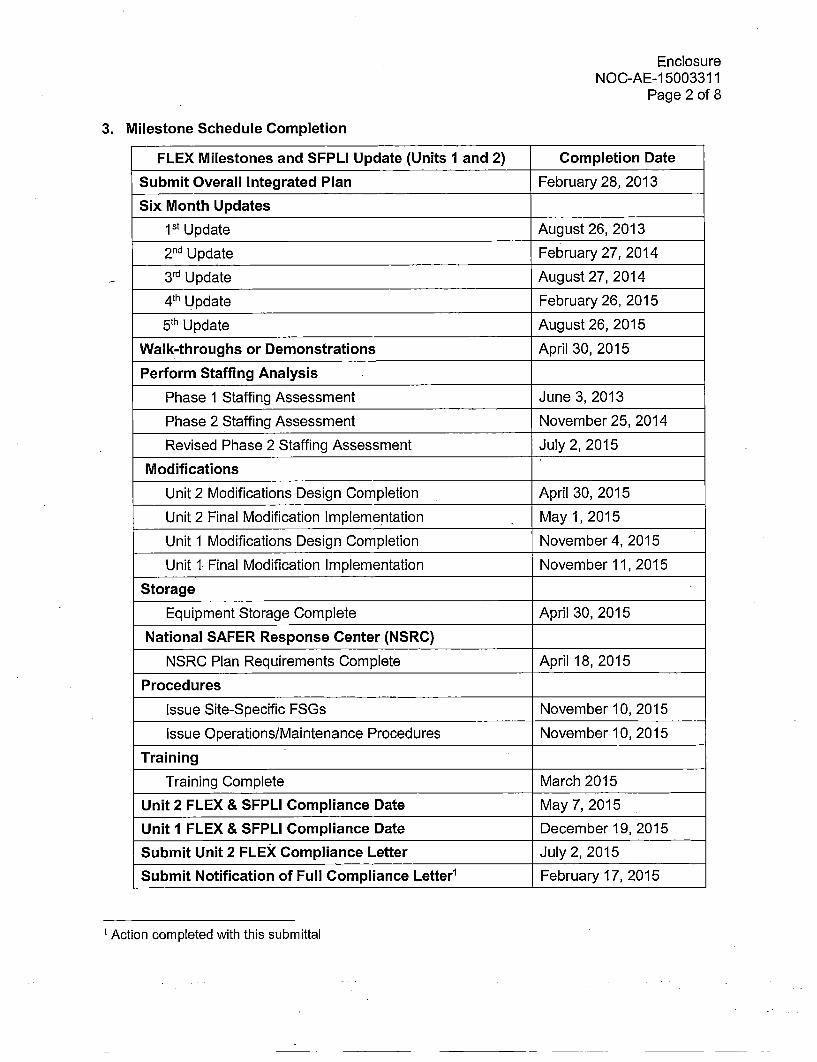
3. Milestone Schedule Completion
FLEX Milestones and SFPLI Update (Units 1 and 2) Completion Date
Submit Overall Integrated Plan February 28, 2013
Six Month Updates
1s Update August 26, 2013
2 nd Update February 27, 2014
3 rd Update August 27, 2014
4 th Update February 26, 2015
5th Update August 26, 2015
Walk-throughs or Demonstrations April 30, 2015
Perform Staffing Analysis
Phase 1 Staffing Assessment June 3, 2013
Phase 2 Staffing Assessment November 25, 2014
Revised Phase 2 Staffing Assessment July 2, 2015
Modifications
Unit 2 Modifications Design Completion April 30, 2015
Unit 2 Final Modification Implementation May 1, 2015
Unit 1 Modifications Design Completion -November 4, 2015
Unit 1 Final Modification Implementation November 11, 2015
Storage
Equipment Storage Complete April 30, 2015
National SAFER Response Center (NSRC)
NSRC Plan Requirements Complete April 18, 2015
Procedures
Issue Site-Specific FSGs November 10, 2015
Issue Operations/Maintenance Procedures November 10, 2015
Training
Training Complete March 2015
Unit 2 FLEX & SFPLI Compliance Date May 7, 2015
Unit 1 FLEX & SFPLI Compliance Date December 19, 2015
Submit Unit 2 FLEX Compliance Letter July 2, 2015
Submit Notification of Full Compliance Letter1 February 17, 2015
1 Action completed with this submittal
EnclosureNOC-AE- 15003311
Page 3 of 8
4. Order EA-12-049 Compliance Elements - Summary
STPNOC has completed implementation of Order EA-12-049 for STP Units 1 and 2
including the following elements:
Strategies - Complete
STP FLEX strategies are in compliance with Order EA-1 2-049. To meet the intent of theOrder, STPNOC followed the guidance provided in NEI 12-06 (Reference 13) with theexception of the Alternate Approaches listed below. These Alternate Approaches havebeen presented to and discussed with the NRC review staff and are noted in the OnsiteAudit Report (Reference 5):
-STP pre-staged some of the FLEX response equipment including two dieselgenerators in protected structures on top of the Mechanical Auxiliary Building(MAB) roof, and pumps, hoses, associated equipment inside existing Class 1plant structures protected against design-basis external events. The primaryreason for pre-staging this equipment is due to difficulties in retrieving anddeploying equipment following a design-basis flooding event.
-STP utilizes two pre-staged pumps with separate injection pathways forReactor Coolant System (RCS) fill instead of a single pump with primary andalternate connection points and injection pathways supplemented by aportable pump. In the STP strategy, the failure of a pre-staged pump wouldrender one of the two injection pathways unavailable as opposed to the twopathways that would be available using the portable pump strategy. As acompensatory measure, STP reduced the allowed out of service time for boththe positive displacement pump (PDP) and FLEX RCS makeup pump andtheir associated connections and flowpaths. STP FLEX strategies also rely onpre-staged pumps for Steam Generator (SG) makeup and SEP makeup,however, STP also has the ability to makeup to these systems using aportable pump.
These alternate approaches are listed in Section 3.5 of the STP FLEX Final IntegratedPlan (F IP) submitted as Attachment 4.
Modifications - Complete
All modifications required to support the FLEX strategies for STP Units 1 and 2 havebeen fully implemented in accordance with station processes.
Equipment - Procured and Maintenance and Testing Performed - Complete
The equipment required to implement the FLEX strategies for STP Units 1 arid 2 hasbeen procured, received, initially tested and performance verified as recommended inaccordance with NEI 12-06 (Reference 13) and is available for use. Maintenance andtesting requirements for FLEX equipment are included in the STP PreventativeMaintenance Program such that equipment reliability is monitored and maintained.
EnclosureNOC-AE-1 5003311
Page 4 of 8
Procedures - Complete
STPNOC has developed FLEX Support Guidelines (FSGs) and integrated them into theexisting procedure framework. Other affected procedures required for FLEXimplementation have also been revised. The FSGs and applicable procedures havebeen verified and are available for use and are being controlled in accordance withstation processes.
Training - Complete
All necessary training has been completed in accordance with the Systematic Approachto Training (SAT) as recommended in NEI 12-06.
Staffing - Complete
The STPNOC Phase 1 Staffing Assessment (Reference 14) was completed inaccordance with the 10 CFR 50.54(f) request for information with respect to Near-TermTask Force (NTTF) Recommendation 9.3 for Emergency Preparedness (Reference 15).The STPNOC Phase 2 Staffing Assessment (Reference 16) was also completed inaccordance with the 10 CFR 50.54(f) letter.
Following the development of the FSGs, STP performed a revalidation of the Phase 2assessment to ensure the FLEX strategies could be implemented as written. STPdetermined that two additional maintenance personnel are required to implement theFLEX strategies for a two unit event in addition to the minimum on-shift staff required bythe Emergency Plan for a single unit event. The needed personnel are currentlyprocedurally obligated to be onsite at all times and STP has implemented administrativecontrols to ensure these staffing levels are maintained.
The results of the revalidation were communicated to the NRC and the Revised Phase 2Staffing Assessment that resulted from the revalidation efforts was submitted to the NRCon July 2, 2015 (Reference 17).
Additionally, during the implementation outage for Unit 1, STP determined that anadditional personnel action was needed for one of the FLEX strategies. In an event suchas a flood from an embankment breach of the Main Cooling Reservoir, the site is floodedto a degree that the Trailer-Mounted Diesel-Driven Pumps (TMDDPs) cannot be used totransfer water to the Auxiliary Feedwater Storage Tank (AFWST) until later in the event.In this case, the condensate Deaerator (DA) can be used as a makeup water source forthe AFWST until flood waters recede.
STP FSG-06 (Reference 18) directs Operators to connect hoses between the DA andthe Auxiliary Feed Pump Test Line Drain Valve which supplies the AFWST. Prior toopening the DA storage tank drain valve, STP determined that the DA must be ventedfor at least seven hours to preclude the release of two-phase water into the transferhoses.
STP reviewed the Revised Phase 2 Staffing Assessment (Reference 17) anddetermined that there would be a person in each unit who could perform this task, if
EnclosureNOC-AE- 15003311
Page 5 of 8
needed, among the on-shift staffing available. Steam suits and hearing protection arestaged in the Turbine Generator Building (TGB) that can be used for completing thisventing action (Reference 18).
A supplement to the Revised Phase 2 Staffing Assessment will be submitted to the NRCto provide additional details (Reference 19).
National SAFER Response Center (NSRC) - Complete
STPNOC has joined the Strategic Alliance for FLEX Emergency Response (SAFER)Team Equipment Committee for off-site facility coordination. A site-specific SAFERResponse Plan has been developed (Reference 20) and the requisite equipment isavailable at the NSRCs to support Phase 3 FLEX implementation in the event that it isneeded.
Validation - Complete
STPNOC has completed validation of the FLEX strategies using station processes andin accordance with industry developed guidance to assure required tasks, manualactions and decisions for FLEX strategies are feasible and may be executed within theconstraints identified in the FLEX strategy timeline.
FLEX Program Document - Established
STPNOC developed a FLEX Program Document (Reference 21) in accordance with therequirements of NEI 12-06. Additionally, STP developed the FLEX FIP that includes asummary of FLEX strategies, descriptions of equipment, and descriptions of applicablehazards (Attachment 4).
EnclosureNOC-AE-1 5003311
Page 6 of 8
References
1. NRC Order Number EA-12-049, "Issuance of Order to Modify Licenses withRegard to Requirements for Mitigation Strategies for Beyond-Design-BasisExternal Events", March 12, 2012 (AE-NOC-12002268)(ML12073A195)
2. Letter from G.T. Powell, STPNOC, to NRC Document Control Desk, "Notification ofCompliance with Orders EA-12-049 for Mitigation Strategies for Beyond-DesignBasis External Events and EA-12-051 for Reliable Spent Fuel Pool Instrumentation(TAC Nos. MF0826 and MF0828)", July 2, 2015 (NOC-AE-1 5003257)(ML1 51 96A031)
3. Letter from D.L. Koehl, STPNOC, to NRC Document Control Desk, "STPNOCOverall Integrated Plan in Response to March 12, 2012 Commission OrderModifying Licenses with Regard to Requirements for Mitigation Strategies forBeyond-Design-Basis External Events (Order Number EA-12-049)", February 28,2013 (NOC-AE-1 3002963)(ML1 3070A01 1)
4. Letter from J.S. Bowen, NRC, to D.L. Koehl, STPNOC, "Interim Staff EvaluationRelating to Overall Integrated Plan in Response to Order EA-12-049 (MitigationStrategies) (TAC Nos. MF0825 and MF0826)", January 29, 2014 (AE-NOC-14002494)(ML1 3339A736)
5. Letter from T. Brown, NRC, to D.L. Koehl, STPNOC, "South Texas Project, Units1 and 2 - Report for the Onsite Audit Regarding Implementation of MitigatingStrategies and Reliable Spent Fuel Instrumentation Related to Orders EA-12-049and EA-12-051 (TAC Nos. MF0825, MF0826, MF0827, and MF0828)", May 6,2015 (AE-NOC-15002661) (ML151 11A465)
6. Letter from G.T. Powell, STPNOC, to NRC Document Control Desk, "STPNOCFirst Six-Month Status Report in Response to March 12, 2012 Commission OrderModifying Licenses with Regard to Requirements for Mitigating Strategies forBeyond-Design-Basis External Events (Order Number EA-12-049)", August 26,2013 (NOC-AE-1 3003027)(ML1 3249A060)
7. Letter from G.T. Powell, STPNOC, to NRC Document Control Desk, "STPNOCSecond Six-Month Status Report in Response to March 12, 2012 CommissionOrder Modifying Licenses with Regard to Requirements for Mitigating Strategiesfor Beyond-Design-Basis External Events (Order Number EA-12-049)", February27, 2014 (NOC-AE-1 4003089)(ML1 4073A458)
8. Letter from G.T. Powell, STPNOC, to NRC Document Control Desk, "STPNOCThird Six-Month Status Report in Response to March 12, 2012 CommissionOrder Modifying Licenses with Regard to Requirements for Mitigating Strategiesfor Beyond-Design-Basis External Events (Order Number EA-12-049)(TAC Nos.MF0825 and MF0826)", August 27, 2014 (NOC-AE-1 40031 62)(ML1 4251 A029)
EnclosureNOC-AE-1 5003311
Page 7 of 8
9. Letter from G.T. Powell, STPNOC, to NRC Document Control Desk, "STPNOCFourth Six-Month Status Report in Response to March 12, 2012 CommissionOrder Modifying Licenses with Regard to Requirements for Mitigating Strategiesfor Beyond-Design-Basis External Events (Order Number EA-12-049)(TAC Nos.MF0825 and MF0826)", February 26, 2015 (NOC-AE-1 5003224)(ML1 5075A01 9)
10. Letter from G.T. Powell, STPNOC, to NRC Document Control Desk, "STPNOCFifth Six-Month Status Report in Response to March 12, 2012 Commission OrderModifying Licenses with Regard to Requirements for Mitigating Strategies forBeyond-Design-Basis External Events (Order Number EA-12-049)(TAC Nos.MF0825 and MF0826)", August 26, 2015 (NOC-AE-15003287)(ML15251A208)
11. NRC Order Number EA-12-051, "Issuance of Order to Modify Licenses withRegard to Requirements for Reliable Spent Fuel Pool Instrumentation," March12, 2012 (AE-NOC-12002271) (ML12054A679)
12. Letter from G.T. Powell, STPNOC, to NRC Document Control Desk, "Report ofFull Compliance with Order EA-12-051 Reliable Spent Fuel PoolInstrumentation," January 19, 2016 (NOC-AE-1 5003297)
13. Nuclear Energy Institute (NEI) Guidance 12-06, "Diverse and Flexible CopingStrategies (FLEX) Implementation Guide," Revision 0, August 21, 2012(ML1 2242A378) .
14. Letter from G.T. Powell, STPNOC, to NRC Document Control Desk, "RevisedPhase 1 Staffing Assessment Submitted in Response to Request for InformationPursuant to 10 CFR 50.54(f) Regarding Recommendation 9.3 of the Near-TermTask Force Review of Insights", June 3, 2013 (NOC-AE-1 3003004)(M L131 82A021 )
15. Letter from E.J. Leeds, NRC, to All Power Reactor Licensees, "Request forInformation Pursuant to Title 10 of the Code of Federal Regulations 50.54(f)Regarding Recommendations 2.1, 2.3, and 9.3 of the Near-Term Task ForceReview of Insights from the Fukushima Dai-lchi Accident", March 12, 2012 (AE-NOC-1 2002269) (ML12053A340)
16. Letter from A. Capristo, STPNOC, to NRC Document Control Desk, "Responseto Request for Information Pursuant to 10 CFR 50.54(f) RegardingRecommendation 9.3 of the Near-Term Task Force Review of Insights from theFukushima Dai-Ichi Accident - Phase 2 Staffing Assessment", November 25,2014 (NOC-AE-1 4003189)
17. Letter from G.T. Powell, STPNOC, to NRC Document Control Desk, "Supplementto Response to Request for Information Pursuant to 10 CFR 50.54(f) RegardingRecommendation 9.3 of the Near-Term Task Force Review of Insights from theFukushima Dai-lchi Accident - Phase 2 Staffing Assessment", JulY 2, 2015(NOC-AE-1 5003255)
18. STP FLEX Support Guideline Procedure, 0POP12-ZO-FSG06, "AlternateAFWST Makeup", Revision 1, November 10, 2015 (STI 34237577)
EnclosureNOC-AE-1 5003311
Page 8 of 8
19. STP Condition Reporting Database Action, CR 12-11657-38
20. STPNOC Vendor Technical Document, VTD-A977-0003, "SAFER ResponsePlan for South Texas Project Electric Generating Station", Revision 0 (STI34077493)
21. STPNOC Document, FLEX-0001, "Diverse and Flexible Coping Strategies(FLEX) Program Document", Revision 0 (STI 33759523)
22. STPNOC Calculation, STP-CP-006, "ELAP Analysis with the South TexasProject RETRAN-02 Input Model", Revision 1, April 15, 2015 (STI 34064235)
Attachment 1NOC-AE-1 5003311
ATTACHMENT 1
Summary of Responses for the FLEX Interim Staff Evaluation Open and Confirmatory Items
Attachment 1NOC-AE-1 5003311
Page 1 of 15
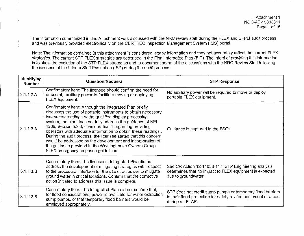
The information summarized in this Attachment was discussed with the NRC review staff during the FLEX and SFPLI audit processand was previously provided electronically on the CERTREC Inspection Management System (IMS) portal.
Note: The information contained in this attachment is considered legacy information and may not accurately reflect the current FLEXstrategies. The current STP FLEX strategies are described in the Final Integrated Plan (FIP). The intent of providing this informationis to show the evolution of the STP FLEX strategies and to document some of the discussions with the NRC Review Staff followingthe issuance of the Interim Staff Evaluation (ISE) during the audit process.
Identifying Question/Request STP ResponseNumber
Confirmatory Item: The licensee should confirm the need for, No auxiliary power will be required to move or deploy3.1.1 .2.A or use of, auxiliary power to facilitate moving or deploying pral LXeupet
FLEX equipment. portable _______FLEX____equipment._____
Confirmatory Item: Although the Integrated Plan brieflydiscusses the use of portable instruments to obtain necessaryinstrument readings at the qualified display processingsystem, the plan does not fully address the guidance of NEI
3.1.1.3.A 1206, Section 5.3.3, consideration 1 regarding providingGudneicatrdnthFSs3.1..3.A operators with adequate information to obtain these readings..GudneicatrdnthFSs
During the audit process, the licensee stated that this concernwould be addressed by the development and incorporation ofthe guidance provided in the Westinghouse Owners GroupFLEX emergency response guidelines.
Confirmatory Item: The licensee's Integrated Plan did notaddress the development of mitigating strategies with respect See CR Action 12-11658-117. STP Engineering analysis
3.1.1 .3.B to the procedural interface for the use of ac power to mitigate determines that no impact to FLEX equipment is expectedground water in critical locations. Confirm that the corrective due to groundwater.action initiated to address this issue is complete.
Confirmatory Item: The Integrated Plan did not confirm that, STP does not credit sump pumps or temporary flood barriers3.1 .2.2.B for flood considerations, power is available for water extraction in their flood protection for safety related equipment or areas
sump pumps, or that temporary flood barriers would beduigaELP______employed appropriately. during ___________an_____ELAP.______
Attachment 1NOC-AE-1 5003311
Page 2 of 15
Identifying Question/Request STP ResponseNumber
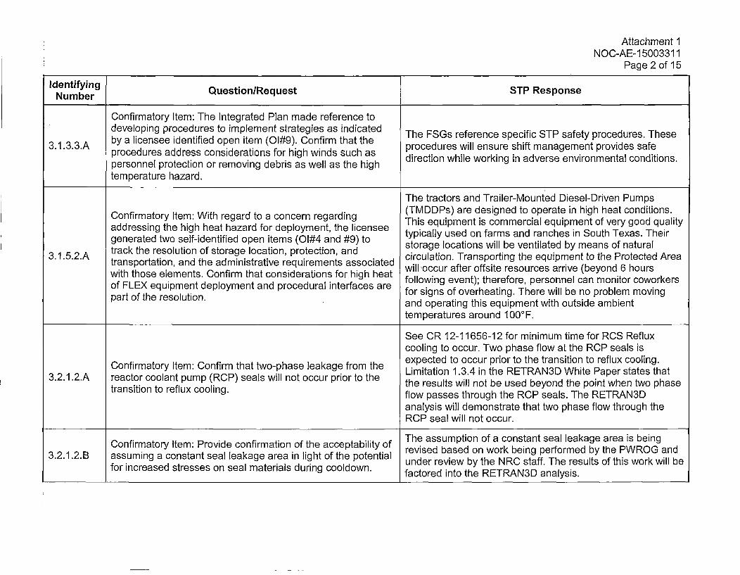
Confirmatory item: The Integrated Plan made reference todeveloping procedures to implement strategies as indicated The FSGs reference specific STP safety procedures. These
3.1.3.3.A by a licensee identified open item (Ol#9). Confirm that the prcdeswlenuehitm ag etpovesaf3133A procedures address considerations for high winds such as prcduresto whillensureinshift managemseentvprovidesta codtosaf
personnel protection or removing debris as well as the high drcinwiewrigi des niomna odtostemperature hazard.
The tractors and Trailer-Mounted Diesel-Driven Pumps
ConfrmaoryIte: Wth egar toa cncen rgaring(TMDDPs) are designed to operate in high heat conditions.ConfrmaoryIte: Wth egar toa cncen rgaringThis equipment is commercial equipment of very good qualityaddressing the high heat hazard for deployment, the licensee tyialusdofrmanrnceinSthTx.Tergenerated two self-identified open items (O1#4 and #9) to storiageylocationfrs wlbevniated bync mean Soft neas.Tuera
3. 52A track the resolution of storage location, protection, and circulation. Transporting the equipment to the Protected Area3.1..2.A transportation, and the administrative requirements associated will occur after offsite resources arrive (beyond 6 hours
with those elements. Confirm that considerations for high heat floigeet;teeoe esne a oio ookr
patof thEX resoutiomn. elyetadpoedritrae r for signs of overheating. There will be no problem movingpartof te reolutonand operating this equipment with outside ambient
temperatures around 100°F.
See CR 12-11656-12 for minimum time for RCS Refluxcooling to occur. Two phase flow at the RCP seals isexpected to occur prior to the transition to reflux cooling.Confirmatory Item: Confirm that two-phase leakage from the Limitation 1.3.4 in the RETRAN3D White Paper states that
3.2.1 .2.A reactor coolant pump (RCP) seals will not occur prior to the the results will not be used beyond the point when two phasetransition to reflux cooling. flow passes through the RCP seals. The RETRAN3D
analysis will demonstrate that two phase flow through theRCP seal will not occur.
The assumption of a constant seal leakage area is beingConfirmatory Item: Provide confirmation of the acceptability of revised based on work being performed by the PWROG and
3.2.1.2.B assuming a constant seal leakage area in light of the potential under review by the NRC staff. The results of this work will befor increased stresses on seal materials during cooldown. factored into the RETRAN3D analysis.
Attachment 1NOC-AE-1 5003311
Page 3 of 15
IdentifyingNumber Question/Request STP Response
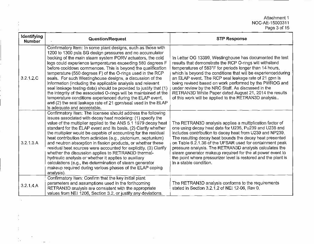
Confirmatory Item: In some plant designs, such as those with1200 to 1300 psia SG design pressures and no accumulatorbacking of the main steam system PORV actuators, the cold In Letter OG 13399, Westinghouse has documented the testlegs could experience temperatures exceeding 580 degrees F results that demonstrate the RCP 0-rings will withstandbefore cooldown commences. This is beyond the qualification temperatures of 583°F for periods longer than 14 hours,temperature (550 degrees F) of the 0-rings used in the RCP which is beyond the conditions that will be experiencedduring
3.2.1.2.0 seals. For such Westinghouse designs, a discussion of the an ELAP event. The RCP seal leakage rate of 21 gpm isinformation (including the applicable analysis and relevant being revised based on work performed by the PWROG andseal leakage testing data) should be provided to justify that (1) under review by the NRC Staff. As discussed in thethe integrity of the associated 0-rings will be maintained at the RETRAN3D White Paper dated August 21, 2014 the resultstemperature conditions experienced during the ELAP event, of this work will be applied to the RETRAN3D analysis..and (2) the seal leakage rate of 21 gpm/seal used in the ELAP
_________is adequate and acceptable.Confirmatory Item: The licensee should address the followingissues associated with decay heat modeling: (1) specify thevalue of the multiplier applied to the ANS 5.1 1979 decay heat The RETRAN3D analysis applies a multiplication factor ofstandard for the ELAP event and its basis. (2) Clarify whether one using decay heat data for U235, Pu239 and U238 andthe multiplier would be capable of accounting for the residual includes contribution to decay heat from U239 and NP239.heat contribution from actinides (e.g., plutonium, neptunium) The resulting decay heat bounds the decay heat presented
3.2.1 .3.A and neutron absorption in fission products, or whether these on Table 6.2.1.36 of the UFSAR used for containment peakresidual heat sources were accounted for explicitly. (3) Clarify pressure analysis. The RETRAN3D analysis calculates thewhether the discussion applies to RETRAN3D thermal- steam generator makeup required for the at power event tohydraulic analysis or whether it applies to auxiliary the point where pressurizer level is restored and the plant iscalculations (e.g., the determination of steam generator in a stable condition.makeup required during various phases of the ELAP copinganalysis).Confirmatory Item: Confirm that the key initial plant
3.2.1.4.A parameters and assumptions used in the forthcoming The RETRAN3D analysis conforms to the requirementsRETRAN3D analysis are consistent with the appropriate stated in Section 3.2.1.2 of NEI 12-06, Rev 0.
__________values from NEI 1206, Section 3.2, or justify any deviations. __________________________
Attachment 1NOC-AE-1 5003311
Page 4 of 15
Numertfyn Question/Request STP Response
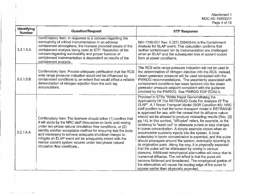
Confirmatory Item: In response to a concern regarding thesurvivability of critical instrumentation in an adverse NAI-1786-001 Rev. 0 (STI 33945544) is the Containmentcontainment atmosphere, the licensee provided details of the Analysis for ELAP event. This calculation confirms that
3.2.1.5.A containment analysis being used at STP. Resolution of the neither containment nor its instrumentation are challengedconcern regarding survivability and proper function of when an ELAP and the subsequent loss of coolant occurscontainment instrumentation is dependent on results of the from at power conditions.containment analysis.
The RCS wide range pressure indication will not be used inConfirmatory Item: Provide adequate justification that the RCS the determination of nitrogen injection into the RCS. Instead,wide range pressure indication would not be influenced by steam generator pressure will be used consistent with the
3.2.1 .5.B containment conditions to an extent that would affect a reliable PWROG recommendations. The uncertainty associated withdetermination of nitrogen injection from the cold leg containment conditions has been factored into the steamaccumulators. generator pressure setpoint consistent with the guidance
provided by the PWROG. See PWROG EOP ECA0.0.
Provided in STPs "White Paper Demonstrating theApplicability Of The RETRAN3D Code For Analysis Of TheELAP". A.1 Boron Transport Model (SER Condition #3). NRCstaff position is that the boron transport model in RETRAN3Dis approved for use, with the caveat that its diffusive nature
Confirmatory Item: The licensee should either (1) confirm that should not be allowed to produce misleading results (Rev. [2]it wll bid bytheNRC taf di cusionon b ricaci miing pg 14). In this context, "diffusive" refers, for example, to theit illabie b th NR stff iscssin o boic cidmixng tendency to "wash out" or attenuate pulses or step changes
under two-phase natural circulation flow conditions, or (2) in boron concentration. A simple example occurs when an
3.2..8.A identify another acceptable method for ensuring that the boric accumulator suddenly injects into the system. A localacidnecssay t aciev adeuat shtdon mrgi topulse/step in boron concentration is expected, and this pulse
mitigate an ELAP event will be adequately mixed with the should propagate around the system, eventually returning to
recutior clowolndtisystem voueudrtopaentrlits origination point. Along the way, it is physically expectedcirclaton low ondtios..that the pulse will be attenuated by mixing in various
plenums. Additional nonphysical attenuation will occur due tonumerical diffusion. The net effect is that the pulse willbecome flattened and broadened. The nonphysical portion ofthe attenuation will cause the leading edge of the pulse toappear earlier than physically expected.
Attachment 1NOC-AE-15003311I
Page 5 of 15
Iumenrfyn Question/Request STP Response
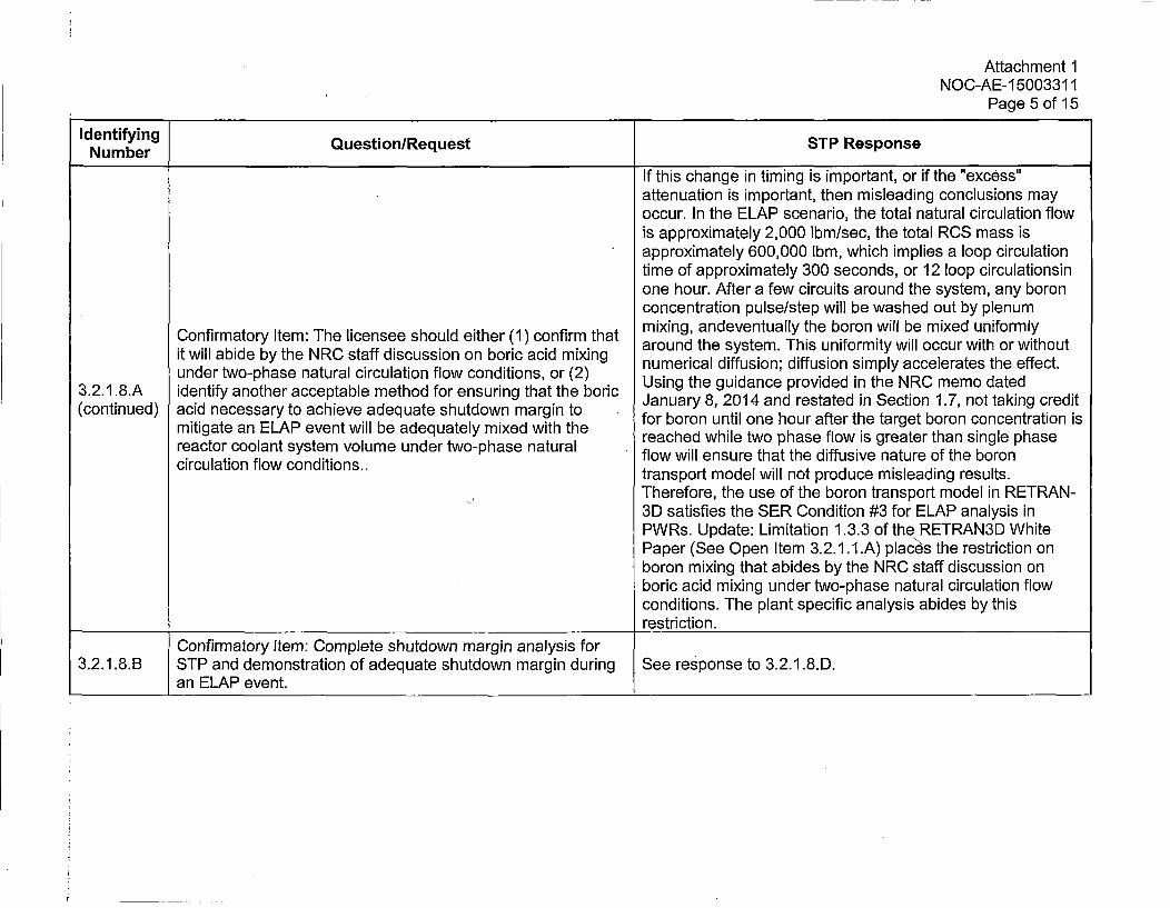
If this change in timing is important, or if the "excess"attenuation is important, then misleading conclusions mayoccur. In the ELAP scenario, the total natural circulation flowis approximately 2,000 lbm/sec, the total RCS mass isapproximately 600,000 Ibm, which implies a loop circulationtime of approximately 300 seconds, or 12 loop circulationsinone hour. After a few circuits around the system, any boronconcentration pulse/step will be washed out by plenum
ConfrmaoryIte: Te liense soul eiher 1) onfrm hatmixing, andeventually the boron will be mixed uniformlyConfrmaoryIte: Te liense soul eiher 1) onfrm hataround the system. This uniformity will occur with or withoutit will abide by the NRC staff discussion on boric acid mixing numerical diffusion; diffusion simply accelerates the effect.under two-phase natural circulation flow conditions, or (2) UsnthgudcepoidinheNCm odad
3.2.1 .8.A identify another acceptable method for ensuring that the boric UsnthgudcepoidinheNCm odad(coninud) cidnecssay t acieveadeuat shtdon mrgi toJanuary 8, 2014 and restated in Section 1.7, not taking credit
(contin mitigated anesar ELA ahevenwilb adequatelyutow mixedgith the for boron until one hour after the target boron concentration ismitiatean EAP ven wil beadeqatey mxed iththe reached while two phase flow is greater than single phase
reactor coolant system volume under two-phase natural flow will ensure that the diffusive nature of the boroncirculation flow conditions.. transport model will not produce misleading results.
Therefore, the use of the boron transport model in RETRAN-3D satisfies the SER Condition #3 for ELAP analysis inPWRs. Update: Limitation 1.3.3 of the RETRAN3D WhitePaper (See Open Item 3.2.1.I.A) plc\ h esrcinoboron mixing that abides by the NRC staff discussion onboric acid mixing under two-phase natural circulation flowconditions. The plant specific analysis abides by this
____ ___ ___ ____ ___ ___ ____ ___ ___ ___ ____ ___ ___ ____ ___ ___ ___ restriction.Confirmatory Item: Complete shutdown margin analysis for
3.2.1.8.B STP and demonstration of adequate shutdown margin during See response to 3.2.1.8.D.an ELAP event.
Attachment 1NOC-AE-1 5003311
Page 6 of 15
Numentryn Question/Request STP Response
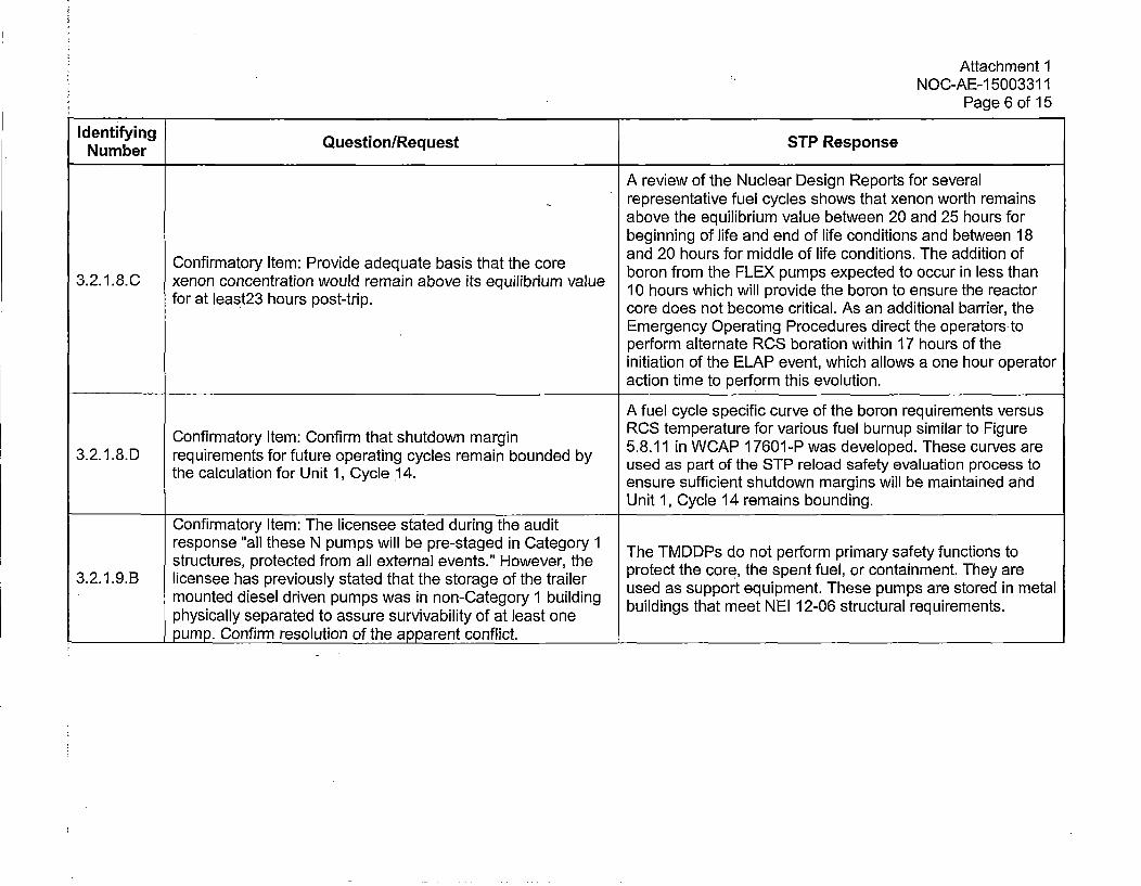
A review of the Nuclear Design Reports for severalrepresentative fuel cycles shows that xenon worth remainsabove the equilibrium value between 20 and 25 hours forbeginning of life and end of life conditions and between 18and 20 hours for middle of life conditions. The addition ofConfirmatory Item: Provide adequate basis that the core boron from the FLEX pumps expected to occur in less than
3.2.1.8.0 xenon concentration would remain above its equilibrium value 10 hours which will provide the boron to ensure the reactor
for t lest2 hous pst-tip.core does not become critical. As an additional barrier, theEmergency Operating Procedures direct the operators toperform alternate RCS boration within 17 hours of theinitiation of the ELAP event, which allows a one hour operatoraction time to perform this evolution.
A fuel cycle specific curve of the boron requirements versusConfrmaory tem Cofirmtha shtdow maginRCS temperature for various fuel burnup similar to Figure
3..1onDfeqirementsory futuem Copeirmtatin cyclesw rmarin bone y 5.8.11 in WCAP 17601-P was developed. These curves areth.18. eqcluaioem nt for funtur opyertn 14. s ean onddb used as part of the STP reload safety evaluation process to
the alclaton or Uit , Ccle14.ensure sufficient shutdown margins will be maintained andUnit 1, Cycle 14 remains bounding.
Confirmatory Item: The licensee stated during the auditresponse "all these N pumps will be pre-staged in Category 1 The TMDDPs do not perform primary safety functions tostructures, protected from all external events." However, the protect the core, the spent fuel, or containment. They are
3.2.1 .9.B licensee has previously stated that the storage of the trailer used as support equipment. These pumps are stored in metalmounted diesel driven pumps was in non-Category 1 building buildings that meet NEI 12-06 structural requirements.physically separated to assure survivability of at least onepump. Confirm resolution of the apparent conflict.
Attachment 1NOC-AE-15003311I
Page 7 of 15
Identifying Qeto/eusINumber Qusin~qetSTP Response
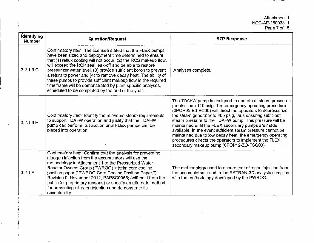
Confirmatory Item: The licensee stated that the FLEX pumpshave been sized and deployment time determined to ensurethat (1) reflux cooling will not occur, (2) the RCS makeup flowwill exceed the RCP seal leak-off and be able to restore
3.2.1.9.0 pressurizer water level, (3) provide sufficient boron to prevent Analyses complete.a return to power and (4) to remove decay heat. The ability of 'these pumps to provide sufficient makeup flow in the requiredtime frame will be demonstrated by plant specific analyses,scheduled to be completed by the end of the year.
The TDAFW pump is designed to operate at steam pressuresgreater than 110 psig. The emergency operating procedure(0POP05-E0-EC00) will direct the operators to depressurize
Confirmatory Item: Identify the minimum steam requirements the steam generator to 405 psig, thus ensuring sufficient3..1.9E to support TDAFW operation and justify that the TDAFW steam pressure to the TDAFW pump. This pressure will be
pump can perform its function until FLEX pumps can be maintained until the FLEX secondary pumps are madeplaced into operation, available. In the event sufficient steam pressure cannot be
maintained due to low decay heat, the emergency operatingprocedures directs the operators to implement the FLEXsecondary makeup pump (0POP12-ZO-FSG03).
Confirmatory Item: Confirm that the analysis for preventingnitrogen injection from the accumulators will use themethodology in Attachment 1 to the Pressurized WaterReactor Owners Group (PWROG) interim core cooling The methodology used to ensure that nitrogen injection from
3.2.1.A position paper ("PWROG Core Cooling Position Paper,") the accumulators used in the RETRAN-3D analysis compliesRevision 0, November 2012, PAPSC0965; (withheld from the with the methodology developed by the PWROG.public for proprietary reasons) or specify an alternate methodfor preventing nitrogen injection and demonstrate its
__________acceptability.____________________________
Attachment 1NOC-AE-1500331 1
Page 8 of 15
Iumentryn Question/Request STP Response
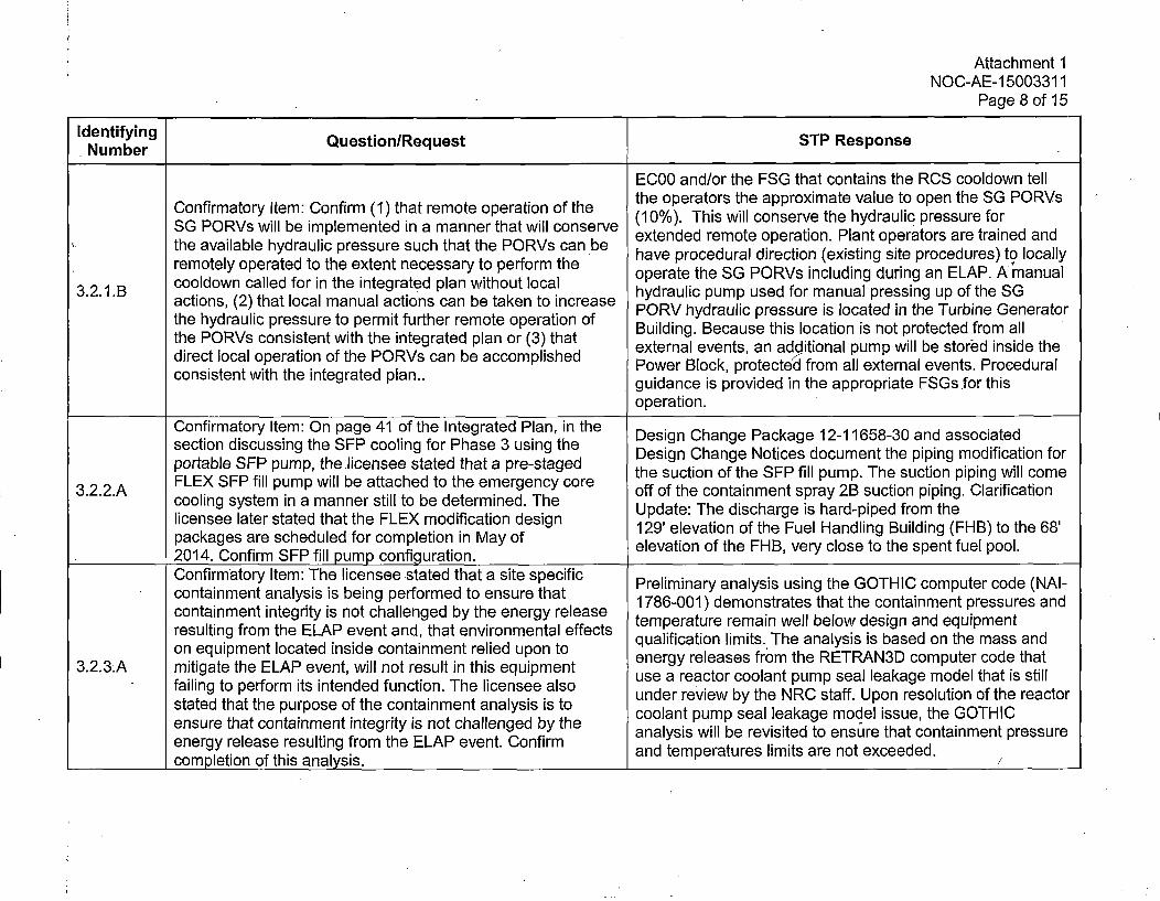
EC00 and/or the FSG that contains the RCS cooldown tellthe operators the approximate value to open the SG PORVsConfirmatory Item: Confirm (1) that remote operation of the (10%). This will conserve the hydraulic pressure for
SG PORVs will be implemented in a manner that will conserve etne eoeoeain ln prtr r rie n
the vaiabl hydaulc pessre sch hatthe OR~ ca be have procedural direction (existing site procedures) to locallyremotely operated to the extent necessary to perform the operate the SG PORVs including during an ELAP. A manual
3.2.1.B cooldown called for in the integrated plan without local hydraulic pump used for manual pressing up of the SGactions, (2) that local manual actions can be taken to increase PRVhdalcpesrisoatdnteTubeGnrtrthe hydraulic pressure to permit further remote operation of Builing Becrauirssue t is location isno prteed furomn Geeall r
drcloaoprtoofthe PORVs conitnawth ntegrated mplanor(3shat externalevns an additional pump will be stored inside thediret lcalopertio ofthe OR~ ca be ccoplihedPower Block, protected from all external events. Procedural
consistent with the integrated plan., guidance is provided in the appropriate FSGs for this
operation.
Confirmatory Item: On page 41 of the Integrated Plan, in the Dsg hnePcae1-15-0adascaesecton iscusin th SEPcooing or has 3 uingtheDesign Change Notices document the piping modification for
portable SEP pump, the licensee stated that a pre-staged the suction of the SEP fill pump. The suction piping will come3..2A FLEX SFP fill pump will be attached to the emergency core off of the containment spray 2B suction piping. Clarification3.2.2.A cooling system in a manner still to be determined. The
licensee later stated that the FLEX modification design Update: The discharge is hard-piped from thepakgsare scheduled for completion in May of 129' elevation of the Fuel Handling Building (FHB) to the 68'
package Cofr F ilp ofgrtoelevation of the FHB, very close to the spent fuel pool.
Confirmatory Item: The licensee stated that a site specific Preliminary analysis using the GOTHIC computer code (NAI-containment analysis is being performed to ensure that1760)deosrtshatecnaim tpesusadcontainment integrity is not challenged by the energy release temperatur remainstwaell below dhesigntainden peqsuip esnt
resutin frm te EAP ven and tht evirnmetaleffcts qualification limits. The analysis is based on the mass andon equipment located inside containment relied upon to energy releases from the RETRAN3D computer code that
3.2.3.A mitigate the ELAP event, will not result in this equipmentusarecocolnpmpellakgmdlthtisilfailing to perform its intended function. The licensee also under review by the NRC staff. Upon resolution of the reactorstated that the purpose of the containment analysis is to coolant pump seal leakage model issue, the GOTHICensure that containment integrity is not challenged by the aayi ilb eiie oesr htcnanetpesrenergy release resulting from the ELAP event. Confirm andlsi temperatresvimitsaed nto exueeded.ntimet rssr
_______completion of this analysis. n eprtrslmisaentecee.
Attachment 1NOC-AE-1500331 1
Page 9 of 15
Identifying Question/Request STP ResponseNumber
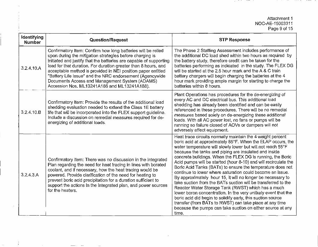
Confirmatory Item: Confirm how long batteries will be relied The Phase 2 Staffing Assessment includes performance ofupon during the mitigation strategies before charging is the additional DC load shed within two hours as required byinitiated and justify that the batteries are capable of supporting the battery study, therefore credit can be taken for theload for that duration. For duration greater than 8 hours, and batteries performing as indicated in the study. The FLEX DG
3.24.1.A acceptable method is provided in NEI position paper entitled will be started at the 2.5 hour mark and the A & C train"Battery Life Issue" and the NRC endorsement (Agencywide battery chargers will begin charging the batteries at the 4Documents Access and Management System (ADAMS) hour mark providing ample margin for starting to charge theAccession Nos. ML13241A186 and ML1 3241Al188). batteries within 8 hours.
Plant Operations has procedures for the de-energizing ofConfrmaoryIte: Povie te reult oftheaddtioal oad every AC and DC electrical bus. This additional loadConfrmaoryIte: Povie te reult oftheaddtioal oad shedding has already been identified and can be easily
shedding evaluation needed to extend the Class 1 E battery referenced in these procedures. There will be no remedial3.2.4.10.B life that will be incorporated into the FLEX support guideline,. esrsbsdsll nd-nriigteeadtoa
Inclde dicusion n rmedal easres equredforde- loads. With all AC power lost, no fans or pumps will beenergizing of additional loads. running so failure closed of AOVs or dampers will not
adversely affect equipment.
Heat trace circuits normally maintain the 4 weight percentboric acid at approximately 850°F. When the ELAP occurs, thewater temperature will slowly lower but will not reach 55°Fbecause the tanks and piping are insulated and insideconcrete buildings. When the FLEX DG is running, the BoricConfirmatory Item: There was no discussion in the integrated Acid pumps will be started (hour 8-10) and will recirculate the
Plan regarding the need for heat tracing in lines with borated Boric Acid Tanks (BATs) to ensure the temperature does notcoolant, and if necessary, how the heat tracing would be continue to lower where saturation could become an issue.
3.2.4.3.A powered. Provide clarification of the need for heating to By approximately hour 15, it will no longer be necessary toprevent boric acid precipitation for a duration sufficient to take suction from the BATs suction will be transferred to thesupport the actions in the integrated plan, and power sources Reactor Water Storage Tank (RWST) which has a much
for te heaerslower boron concentration. In the very unlikely event that theboric acid did begin to solidify early, this suction sourcetransfer (from BATs to RWST) can take place at any timebecause the pumps can take suction on either source at anytime.
Attachment 1NOC-AE-1 5003311
Page 10 of 15
Identifying QetoleusNumber QusinRqetSTP Response
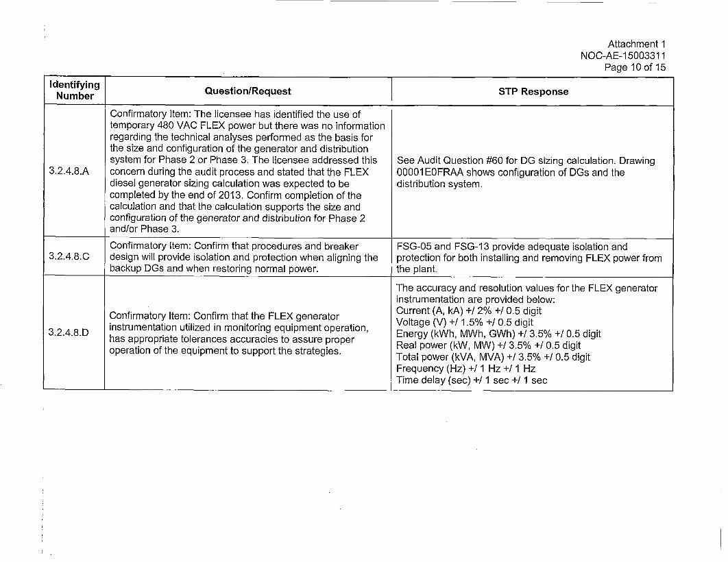
Confirmatory Item: The licensee has identified the use oftemporary 480 VAC FLEX power but there was no informationregarding the technical analyses performed as the basis forthe size and configuration of the generator and distributionsystem for Phase 2 or Phase 3. The licensee addressed this See Audit Question #60 for OG sizing calculation. Drawing
3,2.4.8.A concern during the audit process and stated that the FLEX 00001 EOFRAA shows configuration of DGs and thediesel generator sizing calculation was expected to be distribution system.completed by the end of 2013. Confirm completion of thecalculation and that the calculation supports the size andconfiguration of the generator and distribution for Phase 2and/or Phase 3.
Confirmatory Item: Confirm that procedures and breaker FSG-05 and FSG-1 3 provide adequate isolation and3,2.4.8.C design will provide isolation and protection when aligning the protection for both installing and removing FLEX power from
backup DGs and when restoring normal power. the plant.
The accuracy and resolution values for the FLEX generatorinstrumentation are provided below:
Confirmatory Item: Confirm that the FLEX generator Current (Ak) +/1.2% +/0.5 digit3248D instrumentation utilized in monitoring equipment operation, Vlae()+1.%+ . ii3...8D has appropriate tolerances accuracies to assure proper Renpoerg (kWh, MWhGh) +/3.5% +/ 0.5 digit
operation of the equipment to support the strategies. Retal power (kWA, MWA) +/ 3.5% +/ 0.5 digit
Frequency (Hz) +/1 Hz +/1 HzTime delay (sec) +11 sec +11 sec
Attachment 1NOC-AE-1 5003311
Page 11 of 15
Identifying Question/Request STP ResponseN umber
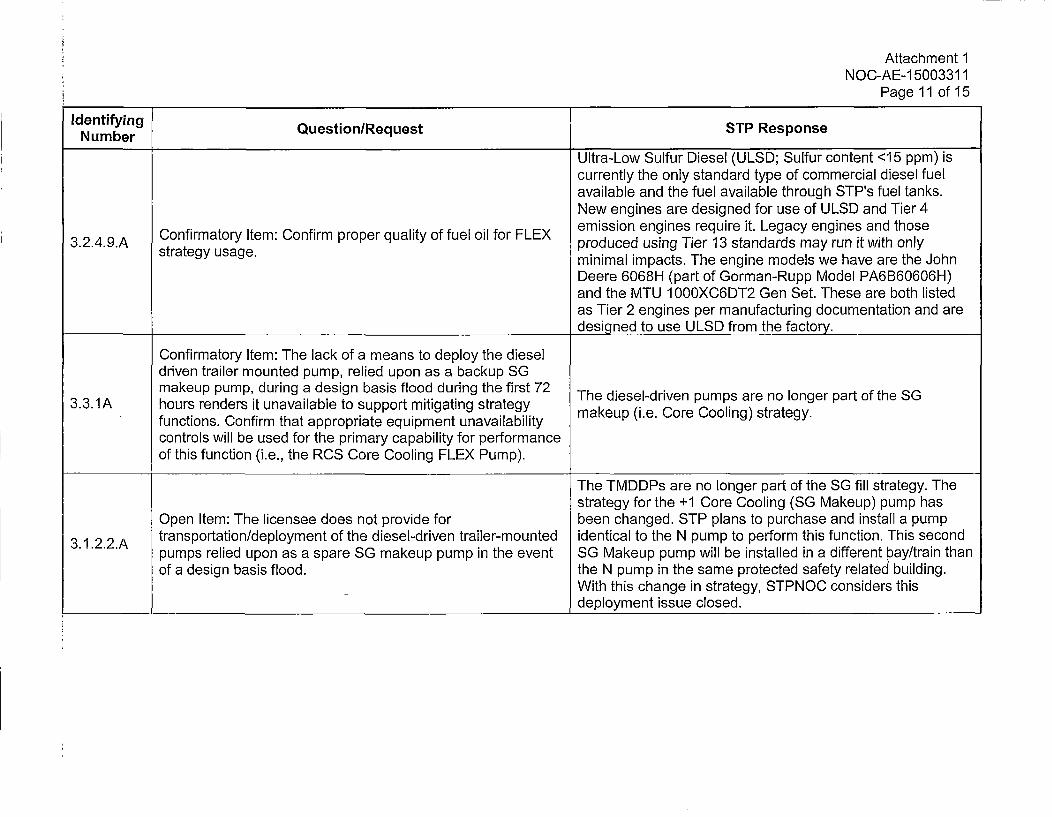
Ultra-Low Sulfur Diesel (ULSD; Sulfur content <15 ppm) iscurrently the only standard type of commercial diesel fuelavailable and the fuel available through STP's fuel tanks.New engines are designed for use of ULSD and Tier 4emission engines require it. Legacy engines and those
3.2.4.9.A Confirmatory Item: Confirm proper quality of fuel oil for FLEX produced using Tier 13 standards may run it with onlystrategy usage. minimal impacts. The engine models we have are the John
Deere 6068H (part of Gorman-Rupp Model PA6B60606H)and the MTU 1000XC6DT2 Gen Set. These are both listedas Tier 2 engines per manufacturing documentation and aredesigned to use ULSD from the factory.
Confirmatory Item: The lack of a means to deploy the dieseldriven trailer mounted pump, relied upon as a backup SGmakeup pump, during a design basis flood during the first 72 Tedee-rvnpmsaen ogrpr fteS
3.3.1A hours renders it unavailable to support mitigating strategy makeup (i.e. Core Cooling) strategy.functions. Confirm that appropriate equipment unavailabilitycontrols will be used for the primary capability for performanceof this function (i.e., the RCS Core Cooling FLEX Pump).
The TMDDPs are no longer part of the SG fill strategy. Thestrategy for the +1 Core Cooling (SG Makeup) pump has
Open Item: The licensee does not provide for been changed. STP plans to purchase and install a pump3.1.2.2.A transportation/deployment of the diesel-driven trailer-mounted identical to the N pump to perform this function. This second
pumps relied upon as a spare SG makeup pump in the event SG Makeup pump will be installed in a different bay/train thanof a design basis flood, the N pump in the same protected safety related building.
With this change in strategy, STPNOC considers thisdeployment issue closed.
Attachment 1NOC-AE-1 5003311
Page 12 of 15
Identifying Question/Request STP ResponseNumber
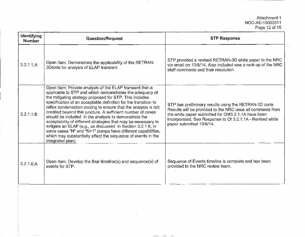
3.2.1.1.A Open Item: Demonstrate the applicability of the RETRAN- STP provided a revised RETRAN-3D white paper to the NRC
via email on 10/8/14. Also included was a rack-up of the NRC3Dcode for analysis of ELAP transient staff comments and their resolution.
Open item: Provide analysis of the ELAP transient that isapplicable to STP and which demonstrates the adequacy ofthe mitigating strategy proposed for STP. This includesspecification of an acceptable definition for the transition to STP has preliminary results using the RETRAN-3D code.reflux condensation cooling to ensure that the analysis is not Results will be provided to the NRC once all comments from
3..11 B credited beyond this juncture. A sufficient number of cases the white paper submitted for O1#3.2.1 1IA have been3.2.11 .B should be included in the analysis to demonstrate the
acceptability of different strategies that may be necessary to incorporated. See Response to OI 3.2.1.1A - Revised whitemitigate an ELAP (e.g., as discussed in Section 3.2.1.6, in paper submitted 10/8/14.
some cases "N" and "N+1" pumps have different capabilities,which may substantially affect the sequence of events in theintegrated plan).
3.2.1.6.A Open Item: Develop the final timeline(s) and sequence(s) of Sequence of Events timeline is complete and has beenevents for STP. provided to the NRC review team.
Attachment 1NOC-AE-1 5003311
Page 13 of 15
Numentryn Question/Request STP Response
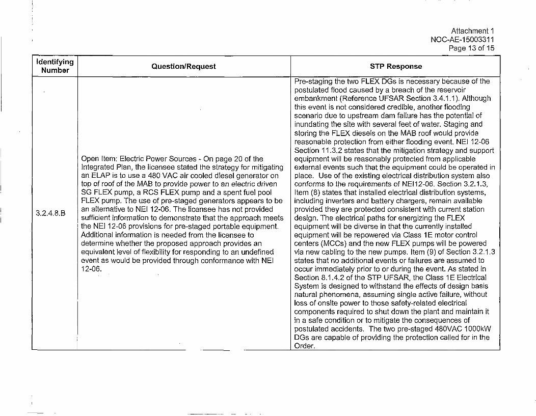
Pre-staging the two FLEX DGs is necessary because of thepostulated flood caused by a breach of the reservoirembankment (Reference U FSAR Section 3.4.1.1 ). Althoughthis event is not considered credible, another floodingscenario due to upstream dam failure has the potential ofinundating the site with several feet of water. Staging andstoring the FLEX diesels on the MAB roof would providereasonable protection from either flooding event. NEI 12-06Section 11.3.2 states that the mitigation strategy and support
Open Item: Electric Power Sources - On page 20 of the equipment will be reasonably protected from applicableIntegrated Plan, the licensee stated the strategy for mitigating external events such that the equipment could be operated inan ELAP is to use a 480 VAC air cooled diesel generator on place. Use of the existing electrical distribution system alsotop of roof of the MAB to provide power to an electric driven conforms to the requirements of NEI12-06. Section 3.2.1.3,SG FLEX pump, a RCS FLEX pump and a spent fuel pool Item (8) states that installed electrical distribution systems,FLEX pump. The use of pre-staged generators appears to be including inverters and battery chargers, remain available
3...8B an alternative to NEI 12-06. The licensee has not provided provided they are protected consistent with current stationsufficient information to demonstrate that the approach meets design. The electrical paths for energizing the FLEXthe NEI 12-06 provisions for pre-staged portable equipment. equipment will be diverse in that the currently installedAdditional information is needed from the licensee to equipment will be repowered via Class 1 E motor controldetermine whether the proposed approach provides an centers (MO~s) and the new FLEX pumps will be poweredequivalent level of flexibility for responding to an undefined via new cabling to the new pumps. Item (9) of Section 3.2.1.3event as would be provided through conformance with NEI states that no additional events or failures are assumed to12-06. occur immediately prior to or during the event. As stated in
Section 8.1.4.2 of the STP UFSAR, the Class 1E ElectricalSystem is designed to withstand the effects of design basisnatural phenomena, assuming single active failure, withoutloss of onsite power to those safety-related electricalcomponents required to shut down the plant and maintain itin a safe condition or to mitigate the consequences ofpostulated accidents. The two pre-staged 480VAC 1000kWDGs are capable of providing the protection called for in theOrder.
Attachment 1NOC-AE- 15003311I
Page 14 of 15
Numertfyn Question/Request STP Response
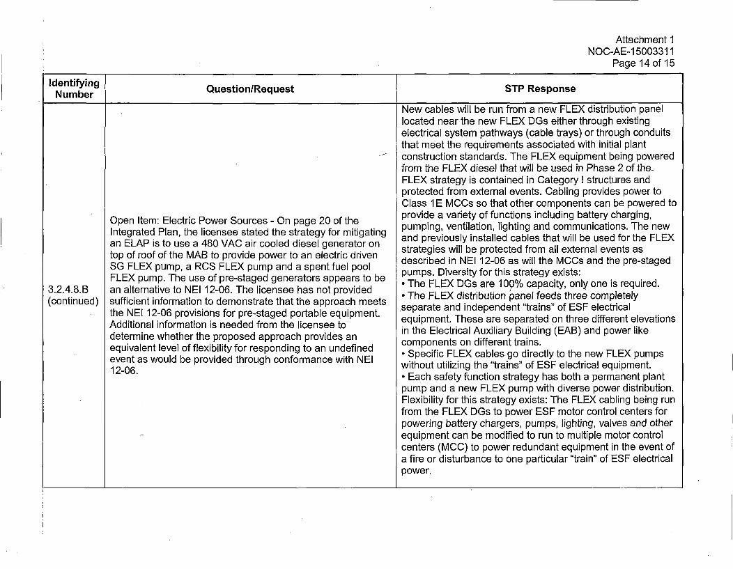
3.2.4.8.B(continued)
Open Item: Electric Power Sources - On page 20 of theIntegrated Plan, the licensee stated the strategy for mitigatingan ELAP is to use a 480 VAC air cooled diesel generator ontop of roof of the MAB to provide power to an electric drivenSG FLEX pump, a RCS FLEX pump and a spent fuel poolFLEX pump. The use of pre-staged generators appears to bean alternative to NEI 12-06. The licensee has not providedsufficient information to demonstrate that the approach meetsthe NEI 12-06 provisions for pre-staged portable equipment.Additional information is needed from the licensee todetermine whether the proposed approach provides anequivalent level of flexibility for responding to an undefinedevent as would be provided through conformance with NEI12-06.
New cables will be run from a new FLEX distribution panellocated near the new FLEX DGs either through existingelectrical system pathways (cable trays) or through conduitsthat meet the requirements associated with initial plantconstruction standards. The FLEX equipment being poweredfrom the FLEX diesel that will be used in Phase 2 of the-FLEX strategy is contained in Category I structures andprotected from external events. Cabling provides power toClass 1 E MCCs so that other components can be powered toprovide a variety of functions including battery charging,pumping, ventilation, lighting and communications. The newand previously installed cables that will be used for the FLEXstrategies will be protected from all external events asdescribed in NEI 12-06 as will the MCCs and the pre-stagedpumps. Diversity for this strategy exists:* The FLEX OGs are 100% capacity, only one is required.* The FLEX distribution joanel feeds three completelySeparate and independent "trains" of ESF electricalequipment. These are separated on three different elevationsin the Electrical Auxiliary Building (EAB) and power likecomponents on different trains.* Specific FLEX cables go directly to the new FLEX pumpswithout utilizing the "trains" of ESF electrical equipment.* Each safety function strategy has both a permanent plantpump and a new FLEX pump with diverse power distribution.Flexibility for this strategy exists: The FLEX cabling being runfrom the FLEX DGs to power ESF motor control centers forpowering battery chargers, pumps, lighting, valves and otherequipment can be modified to run to multiple motor controlcenters (MCC) to power redundant equipment in the event ofa fire or disturbance to one particular "train" of ESF electricalpower.
Attachment 1NOC-AE- 15003311
Page 15 of 15
Identifying Question/Request STP ResponseNumber
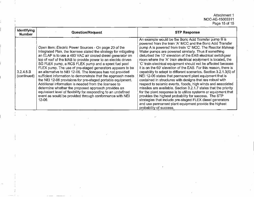
~An example would be the Boric Acid Transfer pump B ispowered from the train 'A' MCC and the Boric Acid Transfer
Open Item: Electric Power Sources - On page 20 of the pump A is powered from train 'C' MOO. The Reactor MakeupIntegrated Plan, the licensee stated the strategy for mitigating Water pumps are powered similarly. Thus if somethingan ELAP is to use a 480 VAC air cooled diesel generator on disturbed the 10' elevation of the EAB electrical switchgeartop of roof of the MAB to provide power to an electric driven room where the 'A' train electrical equipment is located, theSG FLEX pump, a RCS FLEX pump and a spent fuel pool 'C' train electrical equipment should not be affected becauseFLEX pump. The use of pre-staged generators appears to be it is on the 60' elevation of the EAB. For this reason, there is
3.2.4.8.B an alternative to NEI 12-06. The licensee has not provided capability to adapt to different scenarios. Section 3.2.1.3(6) of(continued) sufficient information to demonstrate that the approach meets NEI 12-06 states that permanent plant equipment that is
the NEI 12-06 provisions for pre-staged portable equipment. contained in structures with designs that are robust withAdditional information is needed from the licensee to respect to seismic events, floods, high winds and associateddetermine whether the proposed approach provides an missiles are available. Section 3.2.1.7 states that the priorityequivalent level of flexibility for responding to an undefined for the plant response is to utilize systems or equipment thatevent as would be provided through conformance with NEI provides the highest probability for success. The STP12-06. strategies that include pre-staged FLEX diesel generators
and use permanent plant equipment provide the highest_________ ___________________________________________probability of success.
Attachment 2NOC-AE-1 5003311
ATTACHMENT 2
Update to Response to Open and Pending items from the FLEX and SEPLI Audit Report
Attachment 2NOC-AE-1 5003311
Page 1 of 1
STPNOC provided responses to the Open and Pending items identified in the FLEX/SFPIOnsite Audit Report issued by the NRC (Reference 5) with STP's Order Compliance letter(Reference 2) for Unit 2.
STPNOC has responded to all of the follow-up questions asked by the NRC regarding RCPseals. At this time, no further work is required to validate that STP Units 1 and 2 are incompliance with Order EA-12-049 relative to ROP seal behavior and Westinghouse ELAPanalyses. STP will continue to monitor the discussions between the PWROG and the NRCregarding these issues.
Attachment 3NOC-AE-1 5003311
ATTACHMENT 3
Summary of Responses for Other Issues that Arose after the Audit Report
Attachment 3NOC'-AE- 15003311
Page 1 of 3
The NRC asked STP to respond to two questions regarding the FLEX strategies since theissuance of the STP Onsite Audit Report. The first involved the performance of Westinghouse-style RCP seals under Extended Loss of AC Power (ELAP) conditions. The second involved theseismic surviveability of the FLEX storage buildings not designed to withstand the plant site'sSafe-Shutdown Earthquake (SSE). STP's responses to these two questions are included below.
NRC Question - Plants with Westinghouse-Style Seals and with Mitigation StrategySafety Evaluations (SEs) Outstanding
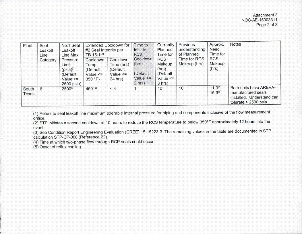
The NRC asked STP the following question in August 2015 and requested that STP provide thesite specific information in the table provided on the following page.
Background: Based on a series of interactions with the PWROG, a number of issuesassociated with the performance of Westinghouse-style ROP seals under ELAP conditions havebeen resolved. However, at present, several key issues remain unresolved, and it appears thatthe PWROG may not be able to resolve them fully on a timescale consistent with the MitigationStrategies Order. These issues include (1) the potential for 1st-stage seal leakoff lineoverpressurization, (2) vendor recommendations for an extended cooldown to ensure second-stage seal integrity (see Westinghouse Technical Bulletin 15-1), and (3) the potential for earlierinitiation of the RCS cooldown and ROS makeup in light of unexpected leakage rate increaseswith time during the recent AREVA Karlstein tests.
STP Response
STP's site specific information was provided to the NRC in the form of the table on the followingpage. The information contained in this table was derived from calculation STP-CP-006(Reference 22).
The table contains revised values for STP and includes additional clarifying notes were added toexplain the changes.
Attachment 3NOC-AE-1 5003311
Page 2 of 3
Plant Seal No.1 Seal Extended Cooldown for Time to Currently -Previous Approx. NotesLeakoff Leakoff #2 Seal Integrity per Initiate Planned understanding Need
Line Line Max TB 15-1(2) RCS Time for of Planned Time forCategory Pressure Cooldown Cooldown Coo1down RCS Time for RCS RCS
Lmt Temp Time (hrs) (hrs) Makeup Makeup (hrs) Makeup
(psia)(1) (Default (Default (hrs) (hrs)(Default Value <= Value <= (Default (DefaultValue >= 350 0F) 24 hrs) Value<= Value <=
2 5 0 0 p s ia ) 2 h rs ) 8 h rs )_ _ _ _ _ _ _ _ _ _ _ _
South 6 2500(3) 450° F < 4 1 10 10 11.*3(4) Both units have ARE VA-Texas 1595 manufactured seals
installed. Understand can_______ ________ ____ ___ _ _______ ________ ___ ___ tolerate > 2500 psia
(1) Refers to seal leakoff line maximum tolerable internal pressure for piping and components inclusive of the flow measurement
orifice.(2) STP initiates a second cooldown at 10 hours to reduce the RCS temperature to below 3500 F approximately 12 hours into the
event.(3) See Condition Report Engineering Evaluation (CREE) 15-15223-3. The remaining values in the table are documented in STP
calculation STP-CP-006 (Reference 22).(4) Time at which two-phase flow through RCP seals could occur.(5) Onset of reflux cooling
Attachment 3NOC-AE-1 5003311
Page 3 of 3NRC Question - FLEX Storage Building Design
.Regarding the seismic design of the two STP FLEX storage buildings, if the buildings are notdesigned to a level commensurate with the plant SSE, provide justification that the equipmentnecessary to mitigate a beyond-design basis seismic event under the conditions of Order EA-12-049 can be deployed successfully. This could be demonstrated by one of the followingmeans:
1. Evaluate the storage buildings to the SSE level and demonstrate its performance isadequate to support fulfillment of the strategies (e.g. does it collapse, fail major/minorstructural members, skew doorframes, etc.)
2. Show that there is another load case (such as wind loading) which governs the buildingdesign such that the building would be functional following an SSE.
3. Show that the equipment stored in the building is not essential for the strategies to
succeed following a seismic event. (This may be applicable to sites who rely heavily onpre-staged FLEX equipment already in other protected buildings.)
4. Show that the reevaluated GMRS [Ground Motion Response Spectrum] seismic hazardis equivalent to or enveloped by the ASCE 7-10 spectra which was used to design thebuilding.
STP Response - FLEX Storage Building Design
STP developed a Condition Report Engineering Evaluation (CREE) in response to this NRCquestion. CREE 12-11658-741 has been provided electronically via the IMS portal and isdiscussed in Section 3.7 of the FIP, "Protection of FLEX Equipment" (Attachment 4).
The CREE confirmed that the wind forces used in the design significantly exceed SSE seismicforces. This is a consequence of the relatively low mass of the one-story buildings, the lowseismicity of the Texas Gulf Coast region, and the relatively high wind forces required by ASCE7-10 in this region. The engineering evaluation estimated SSE seismic forces using the staticequivalent method of seismic analysis and 1.5 times SSE peak acceleration. Therefore, eventhough SSE was not used in the design of the buildings, the higher wind forces that were usedguarantee that the b~uildings will survive the STP design basis SSE earthquake.
Attachment 4NOC-AE-1 5003311
ATTACHMENT 4
STP FLEX Final Integrated Plan (FIP)
Docket Nos. 50-498/499Order EA-12-049
FINAL INTEGRATED PLAN
Beyond Design Basis
FLEX Mitigation Strategies
STP Nuclear Operating Company
STP FLEX Mitigation Strategies Docket Nos. 50-498/499Final Integrated Plan Order EA-12-049
Table of Contents
1. Introduction ......................................................................................... I2. Background.........................................................................................I3. Diverse and Flexible Mitigation Capability (FLEX).............................................. 3
3.1 General Elements - Assumptions ........................................................... 3
3.2 FLEX Mitigation Strategy Overview ......................................................... 5
3.2.1 Reactor Core Cooling Strategy ......................................................... 8
3.2.2 Systems, Structures, Components.................................................... 21
3.2.3 FLEX Strategy Connections ........................................................... 29
3.2.4 Key Reactor Parameters........................................................ ....... 31
3.2.5 Thermal Hydraulic Analyses ........................................................... 32
3.2.6 Shutdown Margin Analysis............................................................. 33
3.2.7 Electrical Analysis ...................................................................... 34
3.3 Spent Fuel Pool Cooling and Inventory ................................................... 34
3.3.1 Phase 1 Strategy........................................................................ 34
3.3.2 Phase 2 Strategy........................................................................ 35
3.3.3 Phase 3 Strategy........................................................................ 36
3.3.4 SFP Makeup Connections ............................................................. 36
3.3.5 Fuel Handling Building Ventilation..................................................... 37
3.3.6 Key Parameters ........................................................................ 37
3.3.7 Thermal-Hydraulic Analyses........................................................... 37
3.3.8 Pumps and Water Supplies for SFP Fill .............................................. 38
3.4 Containment Integrity ....................................................................... 138
3.4.1 Phase I ........................ ........................................................ 38
3.4.2 Phase 2.................................................................................. 39
3.4.3 Phase 3.................................................................................. 39
3.4.4 Equipment for Ventilation Cooling and Spray Strategies............................ 40
3.4.5 Key Containment Parameters ......................................................... 40
3.4.6 Thermal-Hydraulic Analyses........................................................... 40
Pagei
STP FLEX Mitigation Strategies Docket Nos. 50-498/499Final Integrated Plan Order EA-1 2-049
3.5 Alternate Approaches........................................................................ 40
3.6 Characterization of 'External Hazards ..................................................... 41
3.6.1 Seismic .................................................................................. 41
3.6.2 External Flooding....................................................................... 42
3.6.3 Severe Storms with High Wind ........................................................ 43
3.6.4 Ice, Snow and Extreme Cold........................................................... 44
3.6.5 Extreme Heat ........................................................................... 46
3.7 Protection of FLEX Equipment......................46
3.8 Planned Deployment of FLEX Equipment ................................................ 49
3.8.1 Haul Paths................................................................................ 50
3.8.2 Accessibility.............................................................................. 50
3.8.3 Deployment Limitations for the FLEX TMDDPs Due to Flooding................... 51
3.9 Fueling of Equipment........................................................................ 51
3.10 Offsite Resources ........................................................................... 52
3.10.1 National SAFER Response Center.................................................... 52
3.10.2 Equipment List, .............................. i........................................... 56
3.11 Equipment Operating Conditions........................................................... 58
3.11.1 Ventilation and Habitability ...... •.............................................,..........58
3.11.2 Heat Tracing............................................................................. 59
3.12 Lighting................................................................... .................... 60
3.13 Communications ................................. "............................................ 62
3.14 Shutdown and Refueling Modes Analysis ....................... :.......................... 63
3.14.1 Core Cooling and ROS Inventory Control............................................. 64
3.14.2 SFP Strategy .......................................................................... . 64
3.14.3 Containment Strategy................................................................... 65
3.15 Sequence of Events......................................................................... 66
3.16 Programmatic Elements........................68
3.16.1 Overall Program Document............................................................ 68
3.16.2 Procedural Guidance................................................................... 69
Page ii
STP FLEX Mitigation Strategies Docket Nos. 50-498/499Final Integrated Plan Order EA-12-049
3.16.3 Staffing .................................................................................. 70
3.16.4 Training.................................................................................. 71
3.16.5 Equipment List.......................................................................... 71
3.16.6 N+I- Equipment Requirement.......................................................... 75
3.16.7 Equipment Maintenance and Testing ................................................. 76
4.- References........................................................................................ 78
Page iii
STP FLEX Mitigation Strategies Docket Nos. 50-498/499Final integrated Plan Order EA-12-049
List of Tables
Table 3.2.2.2-1 - Qualified Water Sources for FLEX .............................................. 23Table 3.10.2-1 - List of equipment provided by the NSRC........................................ 57Table 3.12-1 - Locations of Appendix R backup battle lanterns.................................. 60Table 3.15-1 - FLEX Sequence of Events Timeline ............................................... 67Table 3.16.5-1 - List of Equipment used in FLEX Strategies ..................................... 73
List of Figures
Figure 3.2.1-1 Diagram of FLEX SG Makeup Strategy .............................................. 9Figure 3.2.1-2 Diagram of FLEX RCS Makeup Strategy........................................... 10Fig ure 3.2.1.2-1 - Photo of SG Makeup Pump..................................................... 14Fig ure 3.2.1.2-2- Diagram of the TMDDP method for SGs Fill................................... 15Fig ure 3.2.1.2-3 - CVCS PDP FLEX Power Transfer Switch..................................... 16Fig ure 3.2.1.2-4 - RCS Makeup Pumps (Modes •1-4 and Modes 5 & 6) ......................... 17
Fig ure 3.2.1.2-5 - AWFST Makeup from the DA................................................... 19Fig ure 3.2.2.2-1 - Typical tank drain at STP........................................................ 25Fig ure 3.2.2.2-2 - AFWST Emergency Fill Method fire water connection ......................... 26Figure 3.2.2.2-3 - AFWST Emergency Fill Method through nitrogen lines ... '.................... 26Figure 3.7-1 - FLEX DG Enclosure, Unit 2 ......................................................... 47Figure 3.10Q.1 -1 - Travel path from Bay City off-site staging area to STP........................ 54Figure 3.10.1-2 - Travel path from Wadsworth off-site staging area to STP .................... 55Figure 3.12-1 - FLEX lighting panel transfer switch ............................................... 61
Page iv
STP FLEX Mitigation StrategiesFinal Integrated Plan
Docket Nos. 50-498/499Order EA-1 2-049
List of Acronyms
AC - Alternating CurrentAFW - Auxiliary Feedwater
AFWST - Auxiliary Feedwater Storage Tank
AOV - Air Operated Valve
ATWS - Anticipated Transient Without Scram
BAT - Boric Acid Tank
BOB - Beyond-Design-Basis
BDBEE - Beyond-Design-Basis ExternalEvent
CCW - Component Cooling Water
CVCS - Chemical and Volume ControlSystem
DA - Deaerator
DC - Direct Current
DCP - Design Change Package
DG - Diesel Generator
DWST - Demineralized Water Storage Tank
ECP - Essential Cooling Pond
ECW - Essential Cooling Water
ELAP - Extended Loss of AC Power
EOP - Emergency Operating Procedure
ESF - Engineered Safety Feature
FHB ~- Fuel Handling Building
FIP - Final Integrated Plan
FLEX - Diverse and Flexible CopingStrategies
FR - Fukushima Response
FSG - FLEX Support GuidelineGMRS - Ground Motion Response Spectrum
HHSI - High Head Safety Injection
LLRW - Low Level Radwaste Building
LOOP - Loss of Offsite Power
LUHS - Loss of Normal Access to theUltimate Heat Sink
MAB - Mechanical Auxiliary Building
MCC - Motor Control Center
MCR - Main Cooling Reservoir
MSL - Mean Sea Level
MSSV - Main Steam Safety Valve
MW - Megawatt
NEI - Nuclear Energy Institute
NRC - Nuclear Regulatory Commission
NSRC - National SAFER Response Center
NSSS - Nuclear Steam Supply System
NTTF - Near-Term Task Force
OBE - Operating Basis Earthquake
OE - Operating Experience
OIP - Overall Integrated Plan
PA - Protected Area
POP - Positive Displacement Pump
PEICo - Pooled Equipment InventoryCompany
PORV - Power Operated Relief Valve
PRT - Pressurizer Relief Tank
Page v
STP FLEX Mitigation StrategiesFinal Integrated Plan
PRV - Pressure Relief Valve
PWROG - Pressurized Water ReactorOwner's Group
QDPS - Qualified Display Processing System
RCFC - Reactor Containment Fan Cooler
RCP - Reactor Coolant Pump
RCS - Reactor Coolant System
RMW - Reactor Makeup Water
RMWST - Reactor Makeup Water StorageTank
RVWL - Reactor Vessel Water Level
RWST - Refueling Water Storage Tank
SAFER - Strategic Alliance for EmergencyResponse
SBO - Station Blackout
SEP - Spent Fuel Pool
SI - Safety Injection
SMUT - Secondary Makeup Tank
SPID - Screening, Prioritization andImplementation Details
SSE - Safe Shutdown Earthquake
STP - South Texas Project
STPEGS - South Texas Project ElectricGenerating Station
STPNOC - South Texas Project NuclearOperating Company
TDAFW Pump - Turbine-Driven AuxiliaryFeedwater Pump
TMDDP - Trailer-Mounted Diesel-DrivenPump
Docket Nos. 50-498/499Order EA-12-049
TRM - Technical Requirements Manual
TS - Technical Specification
TSC - Technical Support Center
UHS - Ultimate Heat Sink*
WR - Wide Range
Page vi
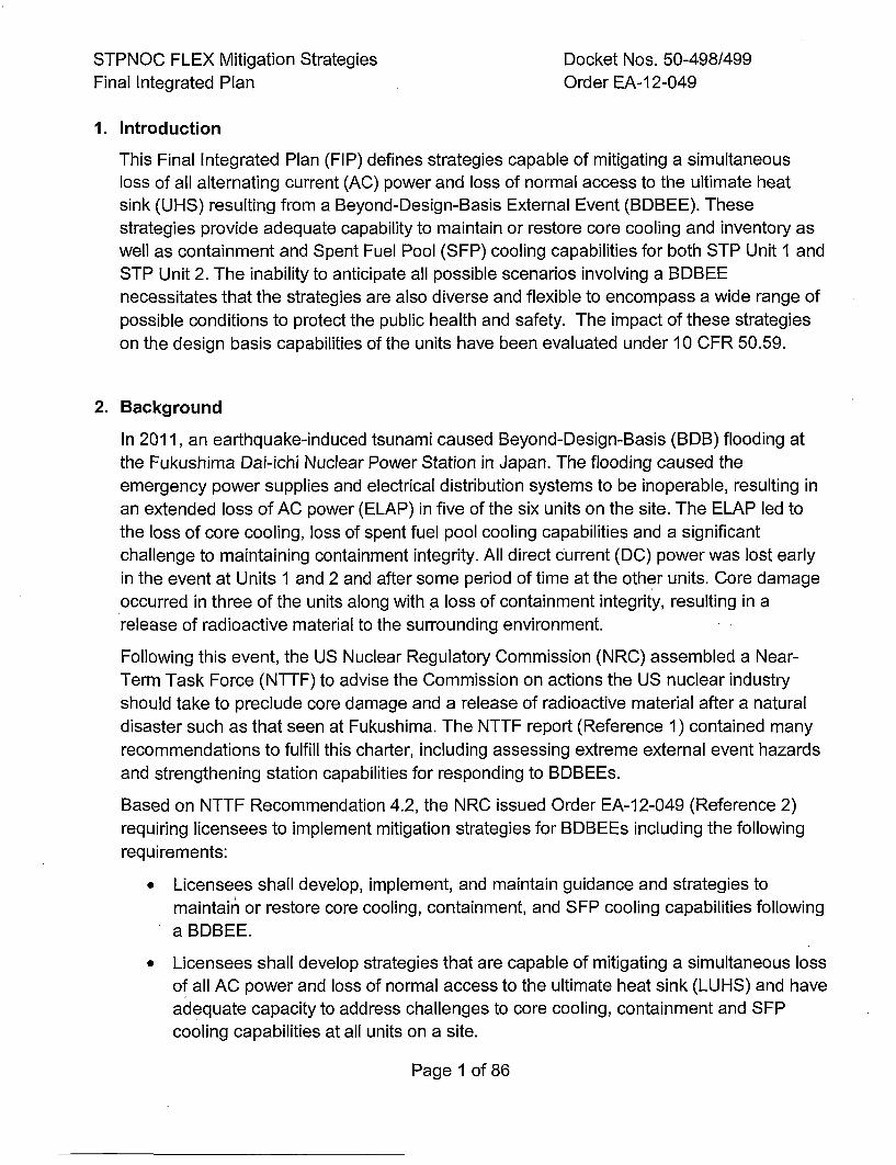
STPNOC FLEX Mitigation Strategies Docket Nos. 50-498/499Final Integrated Plan Order EA-12-049
1. Introduction
This Final Integrated Plan (FIP) defines strategies capable of mitigating a simultaneousloss of all alternating current (AC) power and loss of normal access to the ultimate heatsink (UHS) resulting from a Beyond-Design-Basis External Event (BDBEE). Thesestrategies provide adequate capability to maintain or restore core cooling and inventory aswell as containment and Spent Fuel Pool (SFP) cooling capabilities for both STP Unit I andSTP Unit 2. The inability to anticipate all possible scenarios involving a BDBEEnecessitates that the strategies are also diverse and flexible to encompass a wide range ofpossible conditions to protect the public health and safety. The impact of these strategieson the design basis capabilities of the units have been evaluated under 10 CFR 50.59.
2. Background
In 2011, an earthquake-induced tsunami caused Beyond-Design-Basis (BOB) flooding atthe Fukushima Dai-ichi Nuclear Power Station in Japan. The flooding caused theemergency power supplies and electrical distribution systems to be inoperable, resulting inan extended loss of AC power (ELAP) in five of the six units on the site. The ELAP led tothe loss of core cooling, loss of spent fuel pool cooling capabilities and a significantchallenge to maintaining containment integrity. All direct current (DC) power was lost earlyin the event at Units I and 2 and after some period of time at the other units. Core damageoccurred in three of the units along with a loss of containment integrity, resulting in arelease of radioactive material to the surrounding environment.
Following this event, the US Nuclear Regulatory Commission (NRC) assembled a Near-Term Task Force (NTTF) to advise the Commission on actions the US nuclear industryshould take to preclude core damage and a release of radioactive material after a naturaldisaster such as that seen at Fukushima. The NTTF report (Reference 1) contained manyrecommendations to fulfill this charter, including assessing extreme external event hazardsand strengthening station capabilities for responding to BDBEEs.
Based on NTTF Recommendation 4.2, the NRC issued Order EA-12-049 (Reference 2)requiring licensees to implement mitigation strategies for BDBEEs including the followingrequirements:
*Licensees shall develop, implement, and maintain guidance and strategies tomaintain or restore core cooling, containment, and SFP cooling capabilities following
a BDBEE.
*Licensees shall develop strategies that are capable of mitigating a simultaneous lossof all AC power and loss of normal access to the ultimate heat sink (LUHS) and haveadequate capacity to address challenges to core cooling, containment and SFP
cooling capabilities at all units on a site.
Page 1 of 86
STPNOC FLEX Mitigation Strategies Docket Nos. 50-498/499Final Integrated Plan Order EA-1 2-049
* Licensees must provide reasonable protection for the associated equipment fromexternal events. Such protection must demonstrate that there is adequate capacityto address challenges to core cooling, containment, and SFIp cooling capabilities atall units on a site.
* Licensees must be capable of implementing the strategies in all modes.
* Full compliance shall include procedures, guidance, training, and acquisition, stagingor installing of equipment needed for the strategies.
Order EA-12-049 specifies a three-phase approach for strategies to mitigate BDBEEs. The
initial phase, "Phase 1", requires the use of installed equipment and resources to maintainor restore core cooling, containment and SFP cooling capabilities. The transition phase,"Phase 2", requires providing sufficient, portable, onsite equipment and consumables tomaintain or restore these functions until resources can be brought from off site. The finalphase, "Phase 3" requires obtaining sufficient offsite resources to sustain those functionsindefinitely.
Order EA-12-049 also required licensees of operating reactors to submit an Overall
Integrated Plan (OIP) that included a description of how compliance with theserequirements would be achieved by February 28, 2013 (Reference 3), followed by statusupdates submitted at six-month intervals (References 4 - 8). The Order also requireslicensees to complete implementation of the requirements no later than two refueling cyclesafter submittal of the OIP or by December 31, 2016, whichever comes first.
The Nuclear Energy Institute (NEI) developed NEI 12-06 (Reference 9) which providesguidelines for nuclear stations to assess extreme external event hazards and implementthe mitigation strategies required by Order EA-12-049. The NRC issued Interim StaffGuidance JLD-ISG-2012-01 (Reference 10) endorsing NEI 12-06 with clarifications fordetermining baseline coping capability and equipment quality.
Page 2 of 86
STPNOC FLEX Mitigation Strategies Docket Nos. 50-498/499Final Integrated Plan Order EA-12-049
3. Diverse and Flexible Mitigation Capability (FLEX)
South Texas Project Nuclear Operating Company (STPNOC) has developed the followingFLEX strategies to meet the requirements of Order EA-12-049.
3.1 General Elements - Assumptions
STPNOC established the following plant initial conditions, boundary conditions andassumptions consistent with NEI 12-06 for the purpose of defining FLEX strategies.
Boundary Conditions
* A BDBEE occurs impacting both units at the site.
* All reactors on-site initially operating at power, unless site has procedural directionto shut down due to the impending event.
* Each reactor is successfully shut down when required (i.e., all rods inserted, noATWS).
* On-site staff are at site administrative minimum shift staffing levels.
* No independent, concurrent events, e.g., no active security threat.
* All personnel on-site are available to support site response.
* Spent fuel in dry storage is outside the scope of FLEX.
Initial Conditions
* Prior to the event the reactors have been operating at 100 percent rated thermalpower for at least 100 days or have been shut down as required by plantprocedures in advance of the impending event.
* The reactor and supporting plant equipment are operating within normal ranges for
pressure, temperature and water level, or are available to operate from the standbystate as described in the site design and licensing basis.
*The initiating event is not specific. The initial condition is assumed to be a loss ofoffsite power (LOOP) affecting both units on the site with no prospect for recoveryfor an extended period.
*All installed sources of emergency onsite AC power and station blackout (SBO)Alternate AC power sources are not available and not imminently recoverable.
*Cooling and makeup water inventories contained in systems or structures that arerobust with respect to seismic events, floods, high winds and associated missilesare available.
Page 3 of 86
STPNOC FLEX Mitigation Strategies Docket Nos. 50-498/499Final Integrated Plan Order EA-12-049
*Normal access to the UHS is lost, but the water inventory in the UHS remainsavailable and robust piping connecting the UHS to plant systems remains intact.The motive force for UHS flow (i.e., pumps) is assumed to be lost with no prospectfor recovery.
*, Permanent plant equipment and fuel for FLEX equipment stored in structures thatare robust with respect to seismic events, floods, high winds and associatedmissiles are available.
*Other equipment, such as portable AC power sources, portable back up DC powersupplies, spare batteries, and equipment for 10 CFR 50.54(hh)(2), may be usedprovided it is reasonably protected from the applicable external hazards, haspredetermined hookup strategies with appropriate procedural guidance and theequipment is stored in a relative close vicinity of the site.
*Installed electrical distribution systems, including inverters and battery chargers,
remain available provided they are protected consistent with current station design.
*No additional events or failures occur immediately prior to or during the event,
including security events.
The portion of the fire protection system that is robust with respect to seismicevents, floods, high winds and associated missiles is also available as a water
source.
Reactor Transient Boundary Conditions
o Following the loss of all AC power, both reactors are successfully shut down whenrequired (i.e., all rods inserted, no ATWS).
*Steam release to maintain decay heat removal upon shutdown functions normally,and Reactor Coolant System (RCS) overpressure protection valves respondnormally, if required by plant conditions, and reseat.
* No independent failures, other than those causing the ELAP/LUHS event, are
assumed to occur in the course of the transient.
Reactor Coolant Inventory Loss Assumptions
*Sources of expected reactor coolant inventory loss consist of normal systemleakage from reactor coolant letdown flow (until isolated) and Reactor CoolantPump (RCP) seal leak-off at a rate dependent on RCP seal design.
Page 4 of 86
STPNOC FLEX Mitigation Strategies Docket Nos. 50-498/499Final Integrated Plan Order EA-1 2-049
SFP Initial Conditions
* SFP boundaries and cooling system are intact, including the liner, gates, transfercanal and attached piping.
* Initial loss of SFP inventory from sloshing during a seismic event does not precludeaccess to the refueling deck around the pool.
* The SFP heat load is assumed to be the maximum design basis heat load.
3.2 FLEX Mitiqation Strateqy Overview
The objective of the FLEX strategies is to establish an indefinite coping capability inorder to prevent damage to the fuel in the reactors, maintain the containment functionand maintain cooling and prevent damage to fuel in the SFP using installed equipment,
onsite portable and pre-staged FLEX equipment, and pre-staged offsite resources.
Indefinite coping capability is attained through the implementation of pre-determinedFLEX strategies that are focused on maintaining or restoring key plant safety functions.The FLEX strategies are not tied to any specific damage state or mechanisticassessment of external events. Rather, the strategies are developed to maintain thekey plant safety functions based on the evaluation of plant response to theELAP/LUHS event. The FLEX strategies are diverse and flexible to encompass a widerange of possible conditions.
This safety function-based approach is consistent with the existing site EOPs. FLEXstrategies are implemented in support of the EOPs using the procedures developed forimplementing the FLEX strategies, the FLEX Support Guidelines (FSGs).
The strategies for coping with the plant conditions that result from an ELAP/LUHS
event involve a three-phase approach:
* Phase 1 (Initial Phase) - Initially cope by relying on installed plant equipment andonsite resources.
* Phase 2 (Transition Phase) - Transition from installed plant equipment to onsiteFLEX equipment.
* Phase 3 (Final Phase) - Obtain additional capability and redundancy from offsiteequipment until power, water, and coolant injection systems are restored.
Page 5 of 86
STPNOC FLEX Mitigation Strategies Docket Nos. 50-498/499Final Integrated Plan Order EA-12-049
The duration of each phase is specific to the installed and portable equipment utilizedfor the particular FLEX strategy employed to mitigate the plant condition.
For the Phase 2 or Transition Phase coping actions, the STP FLEX strategies utilizemainly pre-staged equipment instead of portable equipment. This is primarily due tochallenges presented by STPs design basis flooding event. The design basis floodingevent from a breach of the Main Cooling Reservoir (MCR) embankment inundates thesite with water therefore some types of strategies are not feasible (i.e. moving portablepumps from a storage location to the power block to pre-installed connections to theSteam Generators (SGs), the RCS and the SFP). This is considered an AlternateApproach to NEI 12-06.
Additional details regarding the MOR embankment breach scenario are included inSection 3.6.2, "External Flooding". Further details about all of STP's alternateapproaches to the NEI 12-06 guidance are discussed in Section 3.5, "AlternateApproaches".
Narrative Summary of ELAP/LUKS Event Sequence
A timeline of the overall strategy is presented in Table 3.15-1. The ROS responseevents in the timeline are based on analysis assuming the RCP seal leakagepresented in Westinghouse Report PWROG-1 401 5-P (Reference 35).
Phase 1 begins when the ELAP occurs. The reactor trips with all control rods and
shutdown rods inserted. The TDAFW pump begins to feed the D-Train SG within oneminute of the start of the event. The steam generator safety relief valve provides theinitial RCS temperature and pressure control. At four minutes into the event, theleakage from the #1 RCP seal increases to approximately 16.5 gpm. Within tenminutes, Operators are dispatched to restore steam generator PORV control to theControl Room and begin to cross-connect AFW flow from the TDAFW pump to theother three SGs (Reference 11). The #1 seal leak-off line containment isolation valve
is also locally closed, resulting in the #1 RCP seal flow being diverted to the PRTthrough the #1 seal leak-off line (PSV-3200).
Thirty minutes into the event, Operators determine that an ELAP condition hasOccurred and perform the initial assessment of FLEX equipment staging in accordance
with FSG-05 and commence DC load shed of the non-essential equipment inaccordance with FSG-04 (References 22 and 30).
Page 6 of 86
STPNOC FLEX Mitigation Strategies Docket Nos. 50-498/499Final Integrated Pian Order EA-12-049
Forty minutes into the event, flow from the TDAFW pumps is provided to all four SGs.One hour into the event, Operators commence a depressurization of all four SGs to atarget pressure of 405 psig to reduce RCP seal leakage. Approximately 75 minutesinto the event, the pressure in the Pressurizer Relief Tank (PRT) exceeds the rupturedisk design pressure, resulting in the flow from the #1 seal leak-off line being releasedinto containment. The FLEX equipment lineups and connections begin within one totwo hours. Two hours into the event, the DC load shed of non-essential equipment iscompleted.
Within three hours, the SGs are depressurized to 405 psig, which ensures nitrogeninjection from the safety injection (SI) Accumulators into the RCS does not occur.During the depressurization of the SGs and subsequent cooldown of the RCS, theboron addition from the accumulators ensures the reactor remains sub-critical. Aftersix hours, offsite personal resources begin to arrive onsite.
Phase 2 begins in less than eight hours when a FLEX diesel generator (DG) is startedand power becomes available to the FLEX equipment. Within eight hours, the A and Cbattery chargers begin charging batteries. Within ten hours, power to the SIAccumulator isolation valves is made available and these valves are closed, ensuringnitrogen injection into the RCS does not occur. At this time, charging flow of 35 gpm tothe RCS from the BAT or RWST using the PDP is assumed, which provides boron andRCS inventory makeup.
The FLEX steam generator (SG) makeup pump is available by this time to ensureAuxiliary Feedwater (AFW) flow is available in the event t-he SG pressure decreases to
such a point the TDAFW pump can no longer be sustained. The SG Power-OperatedRelief Valves (PORVs) are used to start a second depressurization of the SGs andcooldown and depressurization of the RCS.
The second SG depressurization results in a significant decrease in the #1 RCP seal
leakage. The #1 RCP seal leak-off is terminated when the RCS pressure decreasesbelow the #1 seal leak-off line relief valve reset pressure. As the RCS inventory isrestored, the RCS pressure increases. The IRCS pressure is maintained at a pressure
that ensures that the #1 RCP seal leak-off line relief valve does not re-open, whichoccurs at approximately 15 hours using the reactor vessel upper head vents.
Page 7 of 86
STPNOC FLEX Mitigation Strategies Docket Nos. 50-498/499Final Integrated Plan Order EA-12-049
At approximately 21 hours into the event, the reactor vessel upper head is filled. Flowthrough the reactor vessel upper head vent valves continues for another 30 minutes tocool the metal in the upper head, if required. At approximately 22 hours into the event,the reactor vessel upper head vents are secured and the pressurizer PORV or reactorvessel upper head vents could be used to maintain RCS pressure below the #1 RCP
seal leak-off line relief valve pressure. At approximately 23 hours into the event,pressurizer level is restored and the FLEX RCS makeup pump is secured.
During Phase 2, preparations are made to refill the AFWST. The TMDDP used to fillthe AFWST could also be used to fill the RWST.. At this point, the plant is in a stablecondition. The containment pressure is less than 3 psig and containment temperatureis less than 135°F. The spent fuel pool temperature is less than 212°F.
Phase 3 begins with the arrival of additional equipment from NSRC. Among thisequipment are two 4160V turbine generators which can be connected to anEngineered Safety Feature (ESF) electrical bus.
3.2.1 Reactor Core Coolingq Strategqy
Reactor core cooling involves the removal of decay heat through the secondaryside of the Nuclear Steam Supply System (NSSS) and maintaining sufficientRCS inventory to ensure the continuation of natural circulation in the primary sideof the NSSS. The FLEX strategy for reactor core cooling and decay heatremoval involves releasing steam from the SGs using the SG PORVs and theaddition of a corresponding amount of AFW to the SGs via the Turbine-DrivenAFW (TDAFW) pump. The Auxiliary Feedwater Storage Tank (AFWST) is thewater supply to the TDAFW pump. Operator actions to verify, re-align andthrottle AFW flow are required by STP procedure 0POP05-EO-EC00, "Loss of AllAC Power" (Reference 11) during an ELAP/LUHS event to prevent SG dryout.
Per the EC00 procedure, Operators will initiate RCS cooldown within the first
hour following a BDBEE that triggers an ELAP/LUHS event.
RCS makeup and boron addition will be initiated within 10 hours following aBDBEE to ensure natural circulation, reactivity control, and adequate boronmixing is maintained in the RCS. See Figure 3.2.1-1 and Figure 3.2.1-2, below,for a diagrams of the FLEX SG and FLEX RCS Makeup pathways.
Page 8 of 86
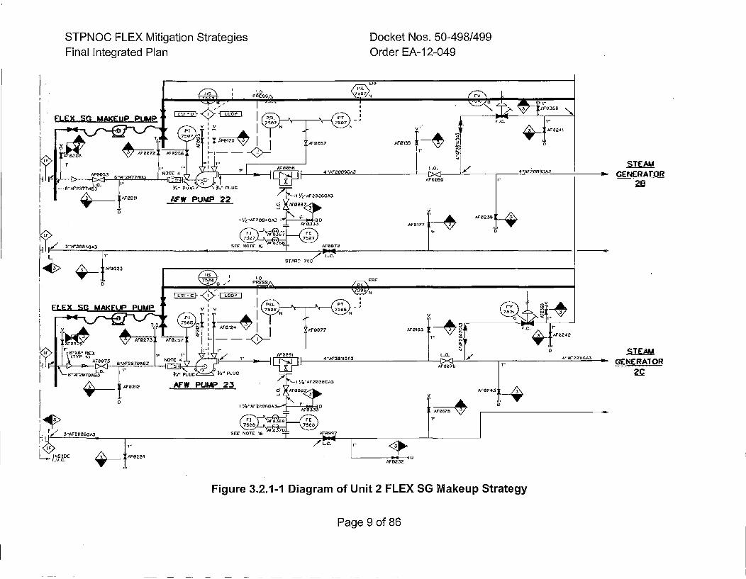
STPNOC FLEX Mitigation StrategiesFinal Integrated Plan
Docket Nos. 50-498/499Order EA-12-049
STEAMGENCRATOR
STEAM,•OtNERATOR
Figure 3.2.1-1 Diagram of Unit 2 FLEX SG Makeup Strategy
Page 9 of 86
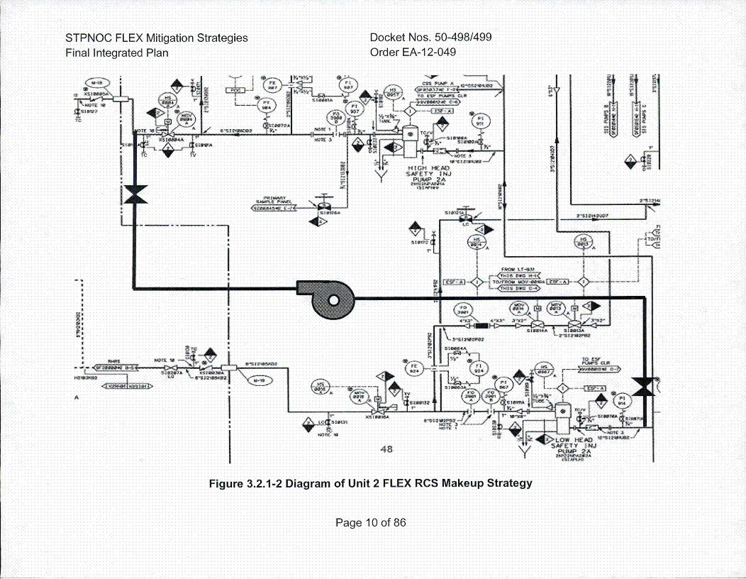
STPNOC FLEX Mitigation StrategiesFinal Integrated Plan
Docket Nos. 50-498/499Order EA-12-049
Figure 3.2.1-2 Diagram of Unit 2 FLEX RCS Makeup Strategy
Page 10 of 86
STPNOC FLEX Mitigation Strategies Docket Nos. 50-498/499Final Integrated Plan Order EA-1 2-049
The reactor core cooling strategies for Phases I through 3, described below, are
the same for STP Unit I and Unit 2.
3.2.1.1 Phase I Stratecqy
The Phase I FLEX strategy for reactor core cooling and heat removalrelies on installed plant equipment and water sources for supplying AFWflow to the SGs.
Operators will respond to the ELAP/LUHS event in accordance with theEOPs. Operators will transition to the EOP for loss of all AC power,0POP05-EO-EC00 (Reference 11), when it is determined that all ACpower has been lost. This procedure directs isolation of RCS letdownpathway, verification of containment isolation, reduction of DC loads onthe station Class 1 E batteries, and alignment of electrical equipment inpreparation for eventual power restoration. Following an ELAP/LUHSevent, the reactor will trip and the plant will initially stabilize at anaverage RCS temperature of approximately 582°F, with reactor decayheat removal via steam release to the atmosphere through the MainSteam Safety Valves (MSSVs). The SG PORVs will fail closed on theloss of power and power must be restored to the SG PORV circuit toallow them to be opened from the Control Room. Natural circulation ofthe RCS will provide core cooling and the TDAFW pump willautomatically provide flow from the AFWST to the D-Train SG to makeup water lost due to the steam release.
During the first hour of the event, Operators will be dispatched locally tore-align AFW flow to all SGs. This will allow the SGs to cooldownsymmetrically. Once the SG PORV control has been restored to theControl Room, then the SG PORVs are opened to reduce pressure tobetween 1130 and 1190 psig so the Main Steam safety valves will close.This reduced RCS temperature to approximately 571°0F. A cooldown ofthe RCS is initiated within the first hour of the event to minimizeinventory loss through the RCP seals per EC00 (Reference 11).
The TDAFW pump starts automatically on SG Low-Low level and doesnot require AC electrical power to provide AFW to the SGs. In the eventthat the TDAFW pump does not start on demand or trips after starting,an operator will restart the TDAFW pump per the EC00 procedure. TheAFW system is normally aligned for the TDAFW pump to deliver flow tothe D-Train SG, so the loss of all AC power EOP directs Operators to
Page 11 of 86
STPNOC FLEX Mitigation Strategies Docket Nos. 50-498/499Final Integrated Plan Order EA-12-049
manually align flow to all four SGs. Manual control of TDAFW pumpflowrate to the SGs for establishing and maintaining proper water levelsin the SGs will be performed locally in the Isolation Valve Cubicle (IVC)per EC00 (Reference 11).
Steam release from the SGs will be controlled remotely from the MainControl Room using hydraulically-operated SG PORVs per EC00. Localmanual operation of the SG PORVs can be performed in the event thathydraulic pressure is expended.
In accordance with the EC00 procedure, RCS cooldown anddepressurization is initiated at a rate of less than 1 00°F/hr to a minimumSG pressure of 405 psig, which corresponds to an RCS core inlettemperature of approximately 450°F. The RCS cooldown minimizes theadverse effects of high temperature RCS coolant on RCP sealperformance and reduces SG pressure to allow for SG injection fromone of the FLEX SG makeup pumps in the event that the TDAFW pumpbecomes unavailable. The minimum SG pressure of 405 psig issufficient to prevent nitrogen gas from the SI Accumulators from entering
,the RCS.
Analysis demonstrates that the plant can maintain this condition for 10hours without the RCP seals experiencing two phase flow or refluxcooling occurring as defined in the NRC endorsement letter for the useof the PWROG NOTRUMP code for ELAP events (Reference 83). STPperforms fuel cycle specific analysis to demonstrate that the reactor coreremains subcritical for this period of time (Reference 84).
AFW supply is provided by the AFWST. Conservatively assuming theinitial water level in the AFWST is at the low level alarm, the usablevolume of this tank provides a sufficient source of AFW for a minimum of32 hours of RCS decay heat removal (Reference 18).
The Phase I equipment including the TDAFW pump, SG PORVs, AFWregulating valves and the AFWST maintain the initial RCS coolingstrategy. The Phase 2 FLEX equipment will be started as needed tosupport longer term cooldown. A FLEX RCS makeup pump for boronaddition will be started to maintain adequate shutdown margin during thecooldown. A FLEX SG makeup pump will be aligned to support replacingthe TDAFW pump when SG pressure will no longer support TDAFWpump operations.
Page 12 of 86
STPNOC FLEX Mitigation Strategies Docket Nos. 50-498/499Final Integrated Plan Order EA-1 2-049
3.2.1.2 Phase 2 Stratecqy
The Phase 2 FLEX strategy for reactor core cooling and heat removalcontinues to rely on feedwater from the AFWST using the TDAFW pumpand, eventually, one of the FLEX SG makeup pumps powered by aFLEX DG.
Once the SI Accumulators have been isolated using FSG-10 (Reference15), Operators initiate a second cooldown and depressurization of theRCS per the EC00 procedure (Reference 11), lowering the SG pressureto below the required 150 psig to run the TDAFW pump (Reference 16).One purpose of this subsequent cooldown and depressurization is to re-seat the Pressure Relief Valve (PRV) on the RCP seal return line thatopened due to the increased RCP seal leakage early in the event. Atabout 12 hours into the event, the PRV should be re-seated (Reference14). At approximately 23 hours following event start, pressurizer levelwill be restored and makeup to the RCS will no longer be required(Reference 14).
Prior to the completion of this second cooldown and depressurization,Operators start one of the two FLEX S'G makeup pumps (Reference 11),fine up the pump to feed all SGs, and secure the TDAFW pump(Reference 17). The FLEX SG makeup pumps take suction on theAFWST and are pre-staged inside the IVC in each unit in the C-Trainand B-Train bays.
During Phase 2, core heat removal via the SGs will be maintainedcontinuously. These FLEX SG makeup pumps are rated for a nominalpressure of 500 psig while flowing at 300 gpm, sufficient size for use inthis strategy (Reference 14). FLEX connections are provided on thesuction piping from the AFWST and on the AFW discharge cross-connect piping. Plant personnel will use FSGs to remove blinds andinstall short hoses and spool pieces in the system to facilitate supplyingwater with the FLEX pumps (References 22 and 17).
See Figure 3.2.1.2-1, below, for a photo of one of the SG makeup
pumps.
Page 13 of 86
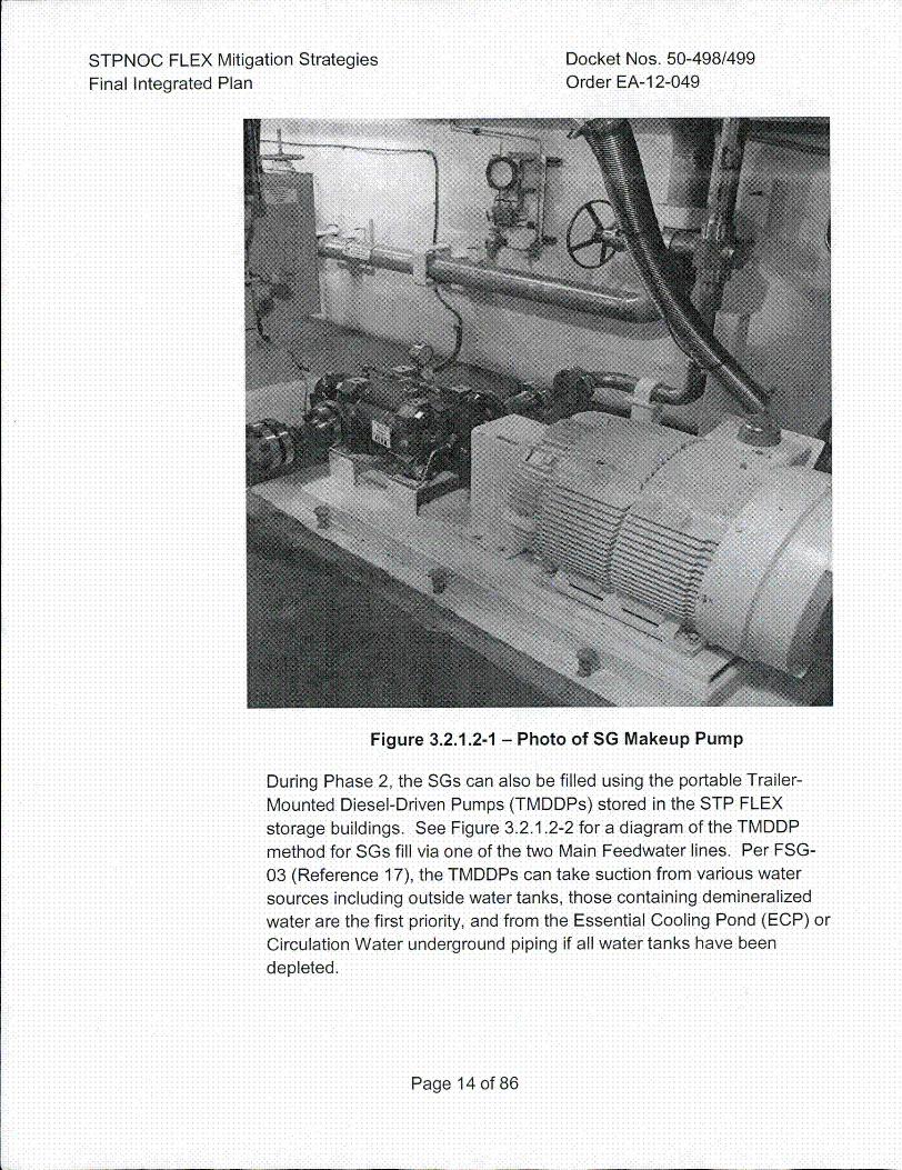
STPNOC FLEX Mitigation StrategiesFinal Integrated Plan
Docket Nos. 50-498/499Order EA-12-049
Figure 3.2.1.2-1 - Photo of SG Makeup Pump
During Phase 2, the S~s can also be filled using the portable Trailer-Mounted Diesel-Driven Pumps (TMDDPs) stored in the STP FLEX
storage buildings. See Figure 3.2.1.2-2 for a diagram of the TMDDP
method for S~s fill via one of the two Main Feedwater lines. Per FSG-
03 (Reference 17), the TMDDPs can take suction from various watersources including outside water tanks, those containing demineralizedwater are the first priority, and from the Essential Cooling Pond (ECP) or
Circulation Water underground piping if all water tanks have been
depleted.
Page 14 of 86
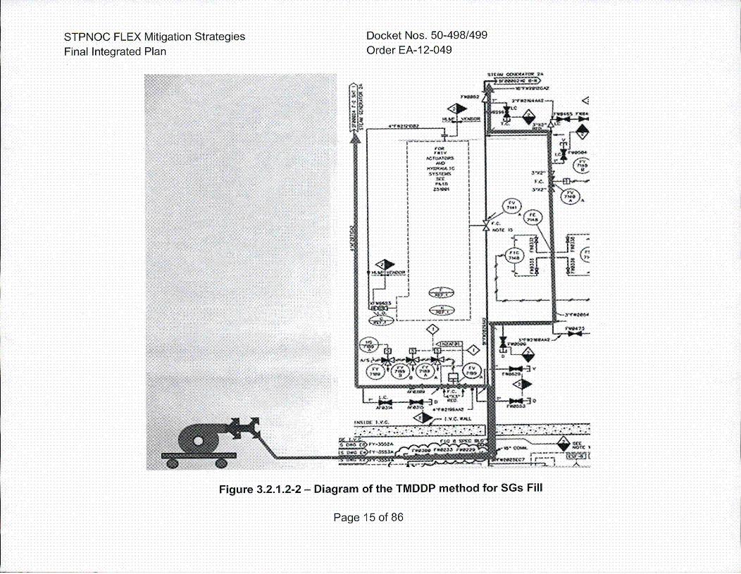
STPNOC FLEX Mitigation StrategiesFinal Integrated Plan
Docket Nos. 50-498/499Order EA-12-049
Figure 3.2.1.2-2 - Diagram of the TMDDP method for SGs Fill
Page 15 of 86
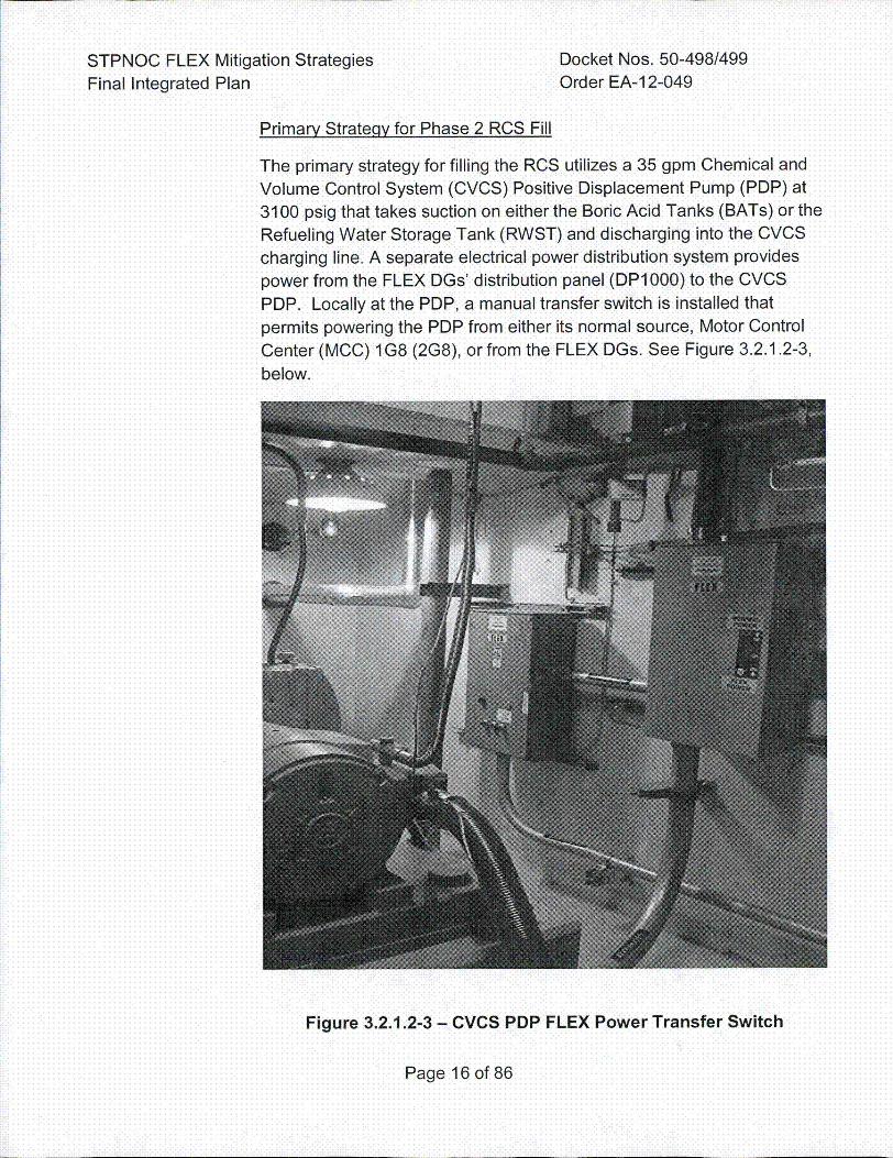
STPNOC FLEX Mitigation Strategies Docket Nos. 50-498/499Final Integrated Plan Order EA-1 2-049
Primary Strateqy for Phase 2 RCS Fill
The primary strategy for filling the RCS utilizes a 35 gpm Chemical and
Volume Control System (CVCS) Positive Displacement Pump (PDP) at3100 psig that takes suction on either the Boric Acid Tanks (BATs) or theRefueling Water Storage Tank (RWST) and discharging into the CVCS
charging line. A separate electrical power distribution system providespower from the FLEX DGs' distribution panel (DP1000) to the CVCSPDP. Locally at the PDP, a manual transfer switch is installed that
permits powering the PDP from either its normal source, Motor ControlCenter (MCC) 1 G8 (2G8), or from the FLEX DGs. See Figure 3.2.1.2-3,
below.
Figure 3.2.1.2-3 - CVCS PDP FLEX Power Transfer Switch
Page 16 of 86
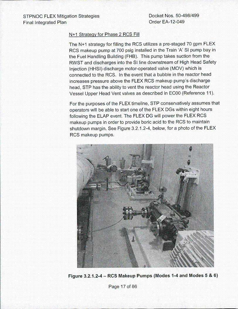
STPNOC FLEX Mitigation Strategies Docket Nos. 50-498/499Final Integrated Plan Order EA-12-049
N+I Strateqy for Phase 2 RCS Fill
The N+I strategy for filling the RCS utilizes a pre-staged 70 gpm FLEX
RCS makeup pump at 700 psig installed in the Train 'A' SI pump bay in
the Fuel Handling Building (FHB). This pump takes suction from the
RWST and discharges into the SI line downstream of High Head Safety
Injection (HHSI) discharge motor-operated valve (MOV) which is
connected to the RCS. In the event that a bubble in the reactor head
increases pressure above the FLEX RCS makeup pump's discharge
head, STP has the ability to vent the reactor head using the Reactor
Vessel Upper Head Vent valves as described in EC00 (Reference 11).
For the purposes of the FLEX timeline, STP conservatively assumes that
operators will be able to start one of the FLEX DGs within eight hours
following the ELAP event. The FLEX DG will power the FLEX RCS
makeup pumps in order to provide boric acid to the RCS to maintain
shutdown margin. See Figure 3.2.1.2-4, below, for a photo of the FLEX
RCS makeup pumps.
Figure 3.2.1.2-4 - RCS Makeup Pumps (Modes 1-4 and Modes 5 & 6)
Page 17 of 86
STPNOC FLEX Mitigation Strategies Docket Nos. 50-498/499Final Integrated Plan Order EA-12-049
STP has elected to use two installed RCS makeup pumps as the N andN+1 RCS fill strategies which is an alternate approach to the NEI 12-06guidance. See Section 3.5 of this document, "Alternate Approaches", foradditional details.
Considerations for Phase 2 RCS Fill Followinq a Flood Event
In the event of a large flood that prohibits movement around the site, theapproximately 474,000 gallons of water are available in the AFWST and148,000 gallons of water in the Condensate Deaerator (DA) can be useduntil flood waters recede (Reference 18). Flow from the DA to theAFWST is accomplished by gravity feed due to the elevation differencesof the two tanks. Figure 3.2.1.2-5 below provides a diagram of theAFWST fill from the DA strategy.
The AFWST has sufficient capacity to provide AFW to the steamgenerators for approximately 32 hours after the initiation of the ELAPevent. During this period, hoses are connected between the DA FLEXFeedwater Isolation Valve and the Auxiliary Feed Pump RecirculationTest Line Drain Valve which supplies the AFWST. Prior to opening theDA FLEX Feedwater Isolation Valve, the DA is vented for at least sevenhours to reduce the pressure and temperature in the deaerator toatmospheric saturation conditions. As noted in FSG-06, if the DA is notallowed proper time for venting, this could result in a release of two-phase water into the transfer hoses. Steam suits and hearing protectionstaged in the Turbine Generator Building (TGB) can be used to supportopening the valves to complete this venting action (Reference 27).
The additional water inventory from the DA extends the capacity of theAFWST to approximately 47 hours. In the event additional makeup to theAFWST could not be provided, the steam generators would containsufficient inventory for approximately 58 hours before a loss of heat sink
would occur.
Page 18 of86
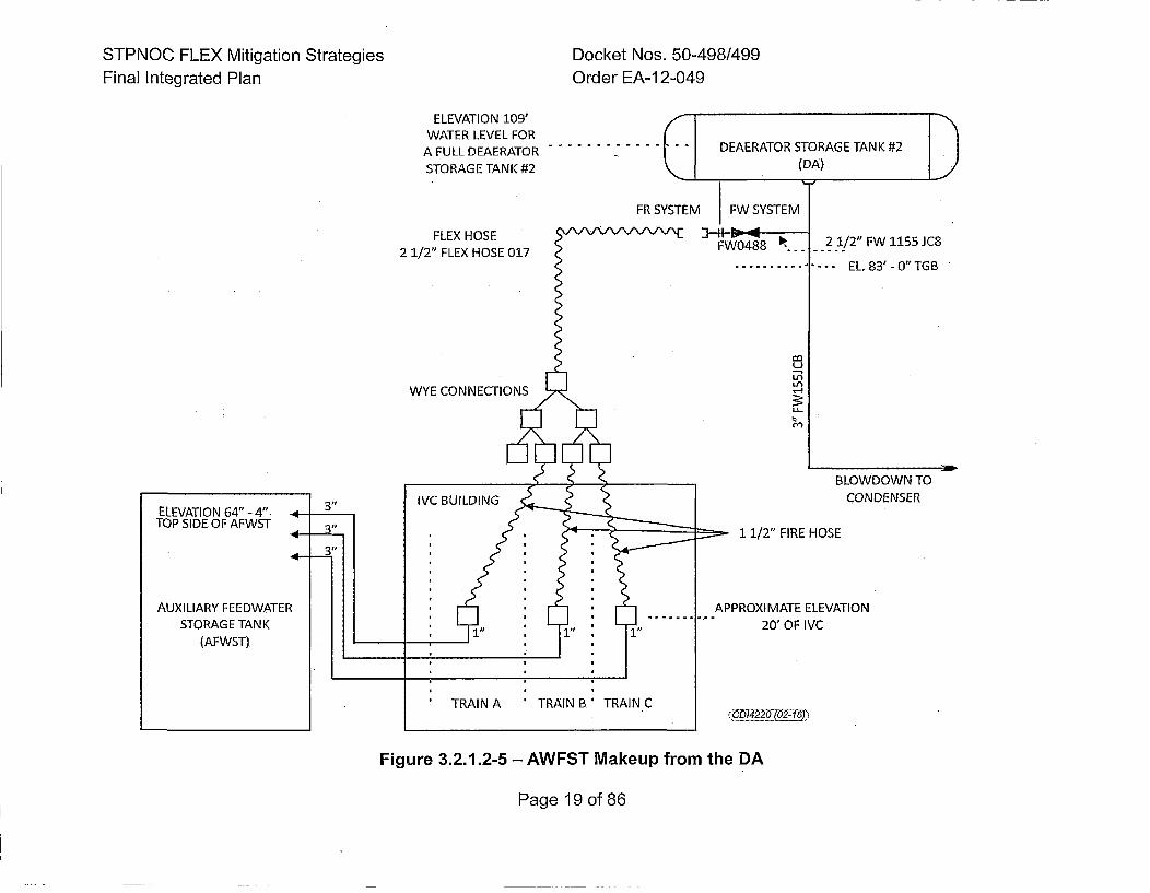
STPNOC FLEX Mitigation StrategiesFinal Integrated Plan
Docket Nos. 50-498/499Order EA-12-049
ELEVATION 109'WATER LEVEL FOR
A FULL DEAERATOR
STORAGE TANK #2
FLEX HOSE2 1/2" FLEX HOSE 017
WYE CONNECTIONS
FW0488 •
-- EL. 83'- 0"TGB
L.i
BLOWDOWN TOCONDENSER
ELEVATION 64" - 4".TOP SIDE OF AFWST
AUXILIARY FEEDWATERSTORAG E TAN K
(AFWST)
1 1/2" FIRE HOSE
APPROXIMATE ELEVATION
. 20' OF IVC
(CDI422O (02-46))C
Figure 3.2.1.2-5 - AWFST Makeup from the DA
Page 19 of 86
STPNOC FLEX Mitigation Strategies Docket Nos. 50-498/499Final Integrated Plan Order EA-1 2-049
3.2.1.3 Phase 3 Strateqy
The Phase 3 FLEX strategies for RCS cooling and heat removalcontinue to rely on the FLEX SG makeup pumps. During this phase,decay heat will eventually decrease to the point that steaming andfeeding the SGs will only be periodically performed. This form of heattransfer can continue indefinitely.
As outlined in FSG-21 (Reference 19), the FLEX SG makeup pumpscan be supplemented by one of the normal permanent plant AFWpumps powered from the Strategic Alliance for EmergencyResponse (SAFER) National Resource Center (NSRC) 4.16 KVturbine generators and AC distribution center that will arrive onsiteapproximately 24 hours following notification of the NSRC. The
NSRC generator can provide power to a motor-driven AFW pump aswell as other equipment on the same electrical bus.
The NSRC 4.16 KV generator provides additional defense-in-depthfor temporary power options and is sized to power one of the three
4.16 KVAC ESF electrical switchgears. The cable tie-in locations forthe NSRC generators are on the downstream side of the ESFtransformers (Reference 19).
Note that the Phase 3 strategy does not rely on the delivery of theNSRC generator for core cooling - the site can continue to copeusing the FLEX SG makeup pumps.
The NSRC will deliver other equipment that can be used for the•Phase 3 core cooling strategy including the following:
* Low pressure, medium flow pump used to fill the SGs. Direction foruse of this pump would come from the Emergency ResponseOrganization (ERO).
• Diesel fuel transfer tank and associated pump used for fueling dieseldriven equipment.
This equipment is listed in the STP SAFER Response Plan andassociated site procedure (References 95 and 20).
Page 20 of 86
STPNOC FLEX Mitigation Strategies Docket Nos. 50-498/499Final Integrated Plan Order EA-12-049
3.2.2 Systems, Structures, Components
The following Structures, Systems, and Components (SSCs) are utilized in theFLEX strategies.
3.2.2.1 Pumps
Turbine-Driven Auxiliary Feedwater Pump
The TDAFW pump is a safety-related, missile protected and seismicallyqualified pump. The TDAFW pump located in the IVC which is designedfor protection from applicable design basis external hazards.
The TDAFW pump should automatically start and deliver AFW flow tothe D-Train SG following an ELAP/LUHS event. Two DC powered steamsupply valves supply steam to the TDAFW pump turbine. These valvesare normally closed and open to admit steam to the turbine on a SGLow-Low level or SI signal. The TDAFW pump turbine steam flow willeither be controlled automatically by the governor valve or manually withthe overspeed trip-throttle valve.
In the event the TDAFW pump fails to start, EC00 and FSG-07(References 11 and 21) direct the operators to manually start the pump.A local vent fan for cooling the TDAFW pump room will be powered oncethe FLEX DG has been started and begins powering the designatedMC~s (Reference 22).
Trailer-Mounted Diesel-Driven Pumps
There are two TMDDPs stored in the FLEX storage buildings locatedoutside the protected area (PA) and a third unprotected pump storedinside the power block that is designated for use in response to mitigate10 CFR 50.54(hh)(2) events. The specifications for these pumps are asfollows: \
* John Deere powered Gorman-Rupp pump
* 20 ft suction lift* Approximately 1000 gpm at greater than 150 psig flowrate and
pressure* 130 gallon fuel tank* 60 ft of 6 inch diameter suction hose including a floating strainer* 3000 ft of 2.5 inch discharge hose
Page 21 of 86
STPNOC FLEX Mitigation Strategies Docket Nos. 50-498/499Final Integrated Plan Order EA-12-049
For the FLEX strategies, the primary function of the TMDDPs is toprovide makeup water to the AFWST and the RWST in both units. Thehighest priority for use of the pump is filling the AFWSTs. The TMDDPswill not be required to makeup to either of these tanks for at least 24hours. After 24 hours, the NSRC will begin providing additional pumpsto perform the same functions.
The secondary function of the TMDDPs is to provide makeup water tothe SGs and the SFP in the event that the N and N+I FLEX makeuppumps are unavailable.
The TMDDPs and hose trailers are strategically separated to increase
the likelihood that one of them survives a large external event.Additionally, the two TMDD pumps in the FLEX buildings have theirwheels chocked to help ensure they are not damaged during a seismic
event. The two pumps stored in the FLEX storage buildings aredeployed to their needed locations by means of four wheel drive tractorsstored with the pumps. The unprotected third pump and hose trailer isstored inside the PA.
FLEX SG Makeup Pumps
SG water injection capability is provided using two pre-staged FLEX SGmakeup pumps (N and N+I) installed inside a Category I building ineach unit. The FLEX SG makeup pumps are rated for a nominalpressure of 500 psig while flowing at 300 gpm. The FLEX SG makeuppumps are 480V motor-driven Centrifugal pumps located in separatebays in the IVO. These pumps provide SG water injection in the eventthat the TDAFW pump can no longer perform its function (e.g. due toinsufficient turbine inlet steam flow from the SG). Hydraulic analyses
have confirmed that the FLEX SG makeup pumps are sized to providethe minimum required SG injection flowrate to support reactor corecooling and decay heat removal (References 23 and 24).
FLEX RCS Makeup Pumps
The N and N+I FLEX RCS makeup pumps are installed in differentlocations inside Category 1 buildings and have different suction anddischarge piping arrangements. The N pump is the CVCS POP whichprovides approximately 35 gpm at 3100 psig. The N+1 pump is acentrifugal pump that provides 70 gpm at 700 psig. The N+1 pump is alower pressure pump because the reactor head can be vented to reducepressure (Reference 11), ensuring this pump is sufficiently sized to fill
Page 22 of 86
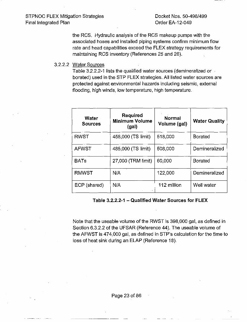
STPNOC FLEX Mitigation StrategiesFinal Integrated Plan
Docket Nos. 50-498/499Order EA-12-049
the RCS. Hydraulic analysis of the RCS makeup pumps with theassociated hoses and installed piping systems confirm minimum flowrate and head capabilities exceed the FLEX strategy requirements formaintaining RCS inventory (References 25 and 26).
3.2.2.2 Water SourcesTable 3.2.2.2-1 lists the qualified water sources (demineralized orborated) used in the STP FLEX strategies. All listed water sources areprotected against environmental hazards including seismic, externalflooding, high winds, low temperature, high temperature.
Water Required Normal WaeQultSucs Minimum Volume VolumeQu(gal)
Sources ~~(gal) Vlm gl
RWST 458,000 (TS limit) 518,000 Borated
AFWST 485,000 (TS limit) 508,000 Demineralized
BATs 27,000 (TRM limit) 60,000 Borated
RMWST N/A 122,000 Demineralized
ECP (shared) N/A 112 million Well water
Table 3.2.2.2-1 - Qualified Water Sources for FLEX
Note that the useable volume of the RWST is 398,000 gal, as defined inSection 6.3.2.2 of the UFSAR (Reference 44). The useable volume ofthe AFWST is 474,000 gal, as defined in STP's calculation for the time to
loss of heat sink during an ELAP (Reference 18).
Page 23 of 86
STPNOC FLEX Mitigation Strategies Docket Nos. 50-498/499Final Integrated Plan Order EA-12-049
The FSGs also list alternate water sources for use in the FLEX
strategies (References 17, 27 and 41), including:
• Secondary Makeup Tank (SMUT), clean water, high usage priority
* Demineralized Water Storage Tank (DWST), clean water, high usagepriority
* Deaerator Storage Tank, SG feedwater, high usage priority
* Fire Water Storage Tank, ground water, medium usage priority
* Service Water Storage Tank, ground water, medium usage priority
• Organics Basin, medium usage priority
* Essential Cooling Water (ECW) Pond, brackish water, low usage
priority
* Circulating Water underground piping, brackish water, low usage
priority
Additional details on the qualified water sources are provided'below.
Auxiliary Feedwater Storaqe Tank
The AFWST is a safety-related, seismic and tornado-missile protectedstructure designed to withstand the applicable design basis externalhazards stated in NEI 12-06. The AFWST is normally aligned to provideemergency makeup water to the SGs and it is the preferred AFW systemwater source at the onset of the ELAP event. Per TechnicalSpecification (TS) 3.7.1.3, the minimum volume of each Unit's AFWST ismaintained at 485,000 gallons. As outlined in FSG-06, following theonset of an ELAP/LUHS event the AFWST will be supplied with waterfrom a variety of sources, including the ECP in a worst-case-scenariousing the TMDDPs (Reference 27). See Figure 3.2.2.2-1, below, for aphoto of a typical tank drain that will be used as a source of water, ifavailable.
Page 24 of 86
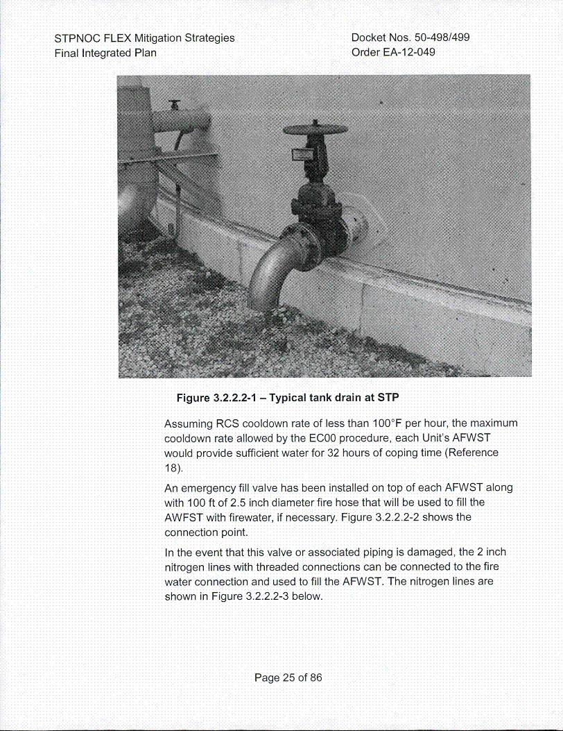
STPNOC FLEX Mitigation StrategiesFinal Integrated Plan
Docket Nos. 50-498/499Order EA-12-049
Figure 3.2.2.2-1 - Typical tank drain at STP
Assuming RCS cooldown rate of less than 100°F per hour, the maximumcooldown rate allowed by the EC00 procedure, each Unit's AFWST
would provide sufficient water for 32 hours of coping time (Reference
18).
An emergency fill valve has been installed on top of each AFWST along
with 100 ft of 2.5 inch diameter fire hose that will be used to fill the
AWFST with firewater, if necessary. Figure 3.2.2.2-2 shows the
connection point.
In the event that this valve or associated piping is damaged, the 2 inch
nitrogen lines with threaded connections can be connected to the fire
water connection and used to fill the AFWST. The nitrogen lines are
shown in Figure 3.2.2.2-3 below.
Page 25 of 86
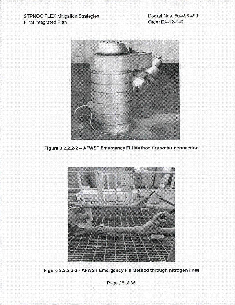
STPNOC FLEX Mitigation StrategiesFinal Integrated Plan
Docket Nos. 50-498/499Order EA-12-049
Figure 3.2.2.2-2 - AFWST Emergency Fill Method fire water connection
Figure 3.2.2.2-3 - AFWST Emergency Fill Method through nitrogen lines
Page 26 of 86
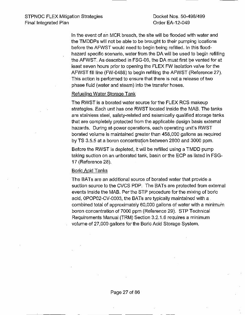
STPNOC FLEX Mitigation Strategies Docket Nos. 50-498/499Final Integrated Plan Order EA-1 2-049
In the event of an MCR breach, the site will be flooded with water and
the TMDDPs will not be able to be brought to their pumping locationsbefore the AFWST would need to begin being refilled. In this flood-hazard specific scenario, water from the DA will be used to begin refillingthe AFWST. As described in FSG-06, the DA must first be vented for atleast seven hours prior to opening the FLEX FW isolation valve for theAFWST fill line (FW-0488) to begin refilling the AFWST (Reference 27).This action is performed to ensure that there is not a release of twophase fluid (water and steam) into the transfer hoses.
Refuelinq Water Storaqe Tank
The RWST is a borated water source for the FLEX RCS makeupstrategies. Each unit has one RWST located inside the MAB. The tanksare stainless steel, safety-related and seismically qualified storage tanks
that are completely protected from the applicable design basis externalhazards. During at-power operations, each operating unit's RWSTborated volume is maintained greater than 458,000 gallons as required
by TS 3.5.5 at a boron concentration between 2800 and 3000 ppm.
Before the RWST is depleted, it will be refilled using a TMDD pumptaking suction on an unborated tank, basin or the ECP as listed in FSG-
17 (Reference 28).
Boric Acid Tanks
The BATs are an additional source of borated water that provide asuction source to the CVCS POP. The BATs are protected from externalevents inside the MAB. Per the STP procedure for the mixing of boricacid, 0POP02-CV-0003, the BATs are typically maintained with acombined total of approximately 60,000 gallons of water with a minimumboron concentration of 7000 ppm (Reference 29). STP Technical
Requirements Manual (TRM) Section 3.2.1.6 requires a minimumvolume of 27,000 gallons for the Boric Acid Storage System.
Page 27 of 86
STPNOC FLEX Mitigation Strategies Docket Nos. 50-498/499Final Integrated Plan Order EA-12-049
Essential Coolinq Water Pond
The ECP is a man-made excavated below grade pond with anapproximately 8 ft high embankment completely surrounding itsperimeter. It is normally filled via the well water system. As stated inUFSAR Section 9.2.5.2, the ECP has a surface area of 39.2 acres at anelevation of 17 ft and 46.5 acres at elevation 25.5 ft. As stated inUFSAR Section 9.2.5.1.1.2, the ECP has approximately 112 milliongallons of storage capacity. If no other water sources are available, oneof the TMDD pumps can be positioned to take suction on this pond anddeliver water to both Units' AFWST and RWST.
3.2.2.3 Other Components
Steam Generator Power Operated Relief Valves
The SG PORVs are safety-related and seismically qualified valves.Power to the SG PORV controllers in the Main Control Room is normallyprovided by Class 1 E 120 VAC power and 480 VAC is supplying thehydraulic pump to maintain hydraulic pressure for normal operation.
During the ELAP event, a relay loses power in the SG PORV circuitry
causing the valves to fail closed. EC00 directs Operators to manipulateSBO switches to re-energize this relay, returning control of the SGPORVs to the Main Control Room (Reference 11). This proceduralaction aids in minimizing field activities and maximizing SG PORVcontrol response.
Operation of the SG PORVs from the Main Control Room will continue
until hydraulic pressure is depleted, at which time manual control will beinitiated via local manual controls. The SG PORVs can be cycled atleast 1 .5 full strokes without the hydraulic pump in operation. A manualhydraulic hand pump located in the TGB can be utilized to locally providehydraulic pressure for additional strokes.
Page 28 of 86
STPNOC FLEX Mitigation Strategies Docket Nos. 50-498/499Final Integrated Plan Order EA-12-049
Class 1 E Batteries
The safety-related Class 1 E batteries and associated DC distributionsystems are located within safety-related structures designed to meetapplicable design basis external hazards. During an ELAP event, thesebatteries are initially relied upon to power required key instrumentationand applicable DC components.
Per FSG-04 (Reference 30), Operators begin stripping all non-essentialloads within one hour following a BDBEE to extend the Class I E batterylife. Load stripping actions will be completed within the next hour.
These actions extend the useable Station Class I1E battery life to at leasteight hours for each unit (Reference 31).
Thee FLEX DGs will be used to repower instrumentation prior to batterydepletion per FSG-19, FSG-05, and FSG-04 (References 32, 22 and30).
3.2.3 FLEX Strateqiy Connections
Primary SG Makeup Pump Connection
The primary connections to supply makeup water to the SGs are located on theAFW system suction and cross-connect lines in the IVO. Following the ELAP
event, flexible hoses or spool pieces will be routed from the FLEX SG makeuppump suction and discharge to the primary connections in the AFW system per
FSG-03 (Reference 17). Hydraulic analyses of the flowpaths confirmed thatapplicable performance requirements are met (References 23 and 24). IVCTrain B and C bays each contain a FLEX SG makeup pump. Each train isseparated by individual watertight doors. One of the two FLEX SG makeup 'pumps is the N FLEX SG makeup pump. The pump used for the primary N pumphas its own independent connection points associated with that train.
Alternate SG Makeup Connection
In the event that the N SG makeup pump is not available for makeup to the S~s,the N+I FLEX SO makeup pump will be used. The N+l pump is located in theother Train bay of the IVC and utilizes alternate suction and dischargeconnection points.
Page 29 of 86
STPNOC FLEX Mitigation Strategies Docket Nos. 50-498/499Final Integrated Plan Order EA-1 2-049
Primary RCS Connection
The primary connection for RCS makeup is via the CVCS system using thepermanent plant PDP installed in the MAB. Normal CVCS piping is used for thesuction and discharge flowpaths. The BATs are the primary suction source forthe OVCS PDP and the RWST is available as a secondary suction source.
Alternate RCS Makeup Connection
The alternate connection for RCS makeup is via the RCS makeup FLEX pumpinstalled in the FHB. The suction connection is located on the SI suction headerfor the A-Train SI pump and the discharge connection is downstream of the A-Train HHSI pump discharge MOV to the RCS hot leg. As directed by FSG-08,flexible hoses are used to attach the FLEX pump to the SI suction and dischargepiping (Reference 33).
480 VAC Electrical Power Connections
The two 1-MW FLEX DGs provide power to both the RCS makeup and the SGmakeup pumps by means of permanent power distribution circuits. The FLEXDGs are located on the MAB roof in a missile protected enclosure. Separateelectric power distribution feeds from the independent FLEX DGs can provide
power to the FLEX Distribution Panel. An interlock is provided to only allow oneFLEX DG to be aligned to the FLEX Distribution Panel. The FLEX Distributionpanel provides a direct electrical AC power source to the FLEX components
independent from the site's normal electrical distribution system. FLEX electricalpower circuits have been permanently installed inside Category I buildings to
ensure a quick and dependable response to the ELAP event.
4160 VAC Electrical Power Connections
Two 1-MW 4160 VAC generators delivered to each STP Unit from the NSRC canbe connected to ESF transformers on the downstream (load) side. Thedeployment location for the NSRC generators is the area near the ESF
transformers. The NSRC will supply 300 feet of generator cable, affording theflexibility to park the generators in a variety of locations. Operators may elect tomaintain power to loads supplied by the 480V FLEX DG when the NSRCgenerator arrives or to de-energize one train (A, B or C) of the AC busses thatthe FLEX 480V DG was supplying and place this power source in service. TheEmergency Director or Shift Manager will determine which of the three ESFtransformers, if any, will be connected to the NSRC generators, depending onthe needs of the plant and the condition of the individual transformers. This isproceduralized in the FSG-21, "NSRC Turbine Generator"' (Reference 19).
Page 30 of 86
STPNOC FLEX Mitigation Strategies Docket Nos. 50-498/499Final Integrated Plan Order EA-12-049
3.2.4 Key Reactor Parameters
Instrumentation providing the following key parameters is credited for all phasesof the reactor core cooling and decay heat removal strategy with indicationavailable in the Main Control Room:
* Auxiliary Feedwater Flowrate - AFW flowrate indication will be available.
* SG Water Level - SG wide range (WR) water level indication will be available.
* SG Pressure - SG pressure indication will be available in the Main ControlRoom and locally in the IVC for all SGs.
* RCS Temperature - ROS WR hot-leg and cold-leg temperature indication willbe available.
* RCS Pressure - RCS WR pressure indication will be available.
* Core-Exit Thermocouple Temperature - Core-exit thermocouple temperatureindication will be available.
* AFWST Level - AFWST water level indication will be available in the MainControl Room and locally using indication installed on the tank.
* Pressurizer Level - Pressurizer level indication will be available.
* Reactor Vessel Water Level (RVWL) - RCS level indication from the RVWLwill be available.
* Ex-Core Nuclear Instruments - Indication of nuclear, instrumentation activitywill be available.
FLEX equipment is also supplied with local instrumentation necessary foroperating the equipment. FSG-07 and FSG-20 provide guidance for obtaining the
above critical parameters locally when instrument power is unavailable(References 21 and 34).
Page 31 of 86
STPNOC FLEX Mitigation Strategies Docket Nos. 50-498/499Final Integrated Plan Order EA-12-049
3.2.5 Thermal Hydraulic Analyses
3.2.5.1 RCS Response
STP used the RETRAN-3D Input Model to determine RCS response asdocumented in STP calculation STP-CP-006 (Reference 14). Thefollowing conclusions were drawn from the RETRAN ELAP analysis:
* The RCS can be cooled down and maintained at the target steam
generator pressure.
*The boron provided by the SI accumulators to the RCS combinedwith the boron supplied by the RCS makeup pumps from the RWSTor BATs is sufficient to allow the Operators to cool-down the RCS to300°F and ~depressurize the RCS to less than 135 psig within 24hours.
* Flow from the primary FLEX RCS makeup pump is sufficient toborate the RCS to Xenon-free conditions.
*The SG PORVs are adequately sized to maintain the RCS
temperature at or below 300°F and RCS pressure less than 135 psig.
*The alternate N+1 FLEX SG makeup pump may be required toprovide inventory to the SG during Phase 2 due to low steam
pressure to the TDAFW pump.
* Adequate boron mixing occurs under single and two-phase flow
conditions to prevent a return to criticality.
3.2.5.2 Reactor Coolant Pump Seals
The leakage model for the RCP No. 1 seal used in the FLEX strategyanalyses is based on results presented in Westinghouse ReportPWROG-1 4015-P, Revision 2 (Reference 35). STP is a Category 6plant as defined in the Westinghouse Report, however the STP FLEXanalysis conservatively assumed the higher leak rate presented in the
Westinghouse report for a Category I or 6 plant. This leak rate wasused in a site-specific model to determine that the time to ROP sealuncovery occurs at 11.3 hours and reflux cooling occurs at 15.9 hoursfollowing the initiation of the ELAP event.
Page 32 of 86
STPNOC FLEX Mitigation Strategies Docket Nos. 50-498/499Final Integrated Plan Order EA-12-049
The expected timeline to restore flow to the RCS is within four hourswhen using the PDP or within eight hours using the FLEX makeup pumpif the PDP is not available.
While PWROG-14015-P has not yet been approved by the NRC, thefollowing additional conservatisms provide reasonable assurance thatRCP seal uncovery or reflux cooling will not occur:
*The results of the analysis documented in the RETRAN-3D WhitePaper (Reference 36) show that the RETRAN-3D STP computermodel conservatively predicts the time to RCP seal uncovery (13.1hours for RETRAN-3D vs. 13.5 hours for RELAP5) and time to refluxcooling (17.9 hours for RETRAN-3D and 24.9 hours for RELAP5)when compared to a similar RELAP5 STP computer model.
*The Pressurized Water Reactor Owner's Group (PWROG)ITCHSEAL calculations used to determine ROP seal leakage containknown conservatisms when compared to the results of the generic
analysis to the Montereau test data. As discussed in WestinghouseReport PWROG-14074-P, parameters within the ITCHSEALcalculations used for the STP RCP seal leakage values wereadjusted to ensure significant margin when compared the Montereautest data (Reference 37).
*FSG-01 and FSG-08 are used to monitor RCS inventory (e.g. reactor
pressure vessel water level) during the ELAP event and direct theoperators to implement primary makeup more rapidly if signs ofincreased RCP leakage are detected (References 38 and 33).
3.2.6 Shutdown Marqin Analysis
Per the site Core Reload Design Process, STP performs an evaluation for eachfuel cycle to ensure that the reactor maintains a keff of 0.99 or less (Reference84). In addition, Operators are provided curves of the required boronconcentration versus fuel cycle burnup for several RCS temperature conditionsfor equilibrium xenon and xenon free conditions to use as a guide to ensure the
reactor core keff remains at or below 0.99 (References 85 and 86) asrecommended in Westinghouse Report WCAP-1 7601 (Reference 96).
Page 33 of 86
STPNOC FLEX Mitigation Strategies Docket Nos. 50-498/499Final Integrated Plan Order EA-1 2-049
3.2.7 Electrical Analysis
The eight hour Class 1 E battery duty cycle for STP was calculated in accordancewith the IEEE-485 methodology using manufacturer discharge test dataapplicable to the FLEX strategy as outlined in the NEI white paper on extendedbattery duty cycles (References 40 and 97). There are approximately two hoursbetween the calculated battery duration for use in the FLEX strategy and the
expected deployment and startup time for FLEX equipment to supply the DCloads.
Within eight hours of the start of the event, the 480V FLEX DGs will begin re-
powering one battery charger in each of A and C trains.
3.3 Spent Fuel Pool Coolinqi and Inventory
The STP FLEX strategy for maintaining SFP cooling is to monitor SFP level using
remote and local indicators and to provide sufficient makeup water to the SFP tomaintain the normal SFP level. Note that STP has individual SFPs for Unit1I and Unit 2
located in their respective FHBs.
Initial actions to monitor level and, as necessary, stage makeup and spray hoses onthe fuel pool deck need to be completed early in the event. FSG-11I directs plantpersonnel to evaluate the need to provide a ventilation pathway for water vapor toleave the FHB (Reference 41). The most time sensitive scenario occurs with a fullcore offloaded into the SFP.
3.3.1 Phase 1 Strateqiy
During Phase 1, the loss of AC power makes the SFP Cooling and CleanupSystem unable to circulate water through heat exchangers. This causes the SFPto gradually heat up from the decay heat being transferred into the water fronithespent fuel and the water begins to evaporate. To calculate the required makeupwater volume and rate required to maintain normal SFP level, STP assumed theworst-case maximum design heat load for the SFP with every SFP cellcontaining a spent fuel assembly.
The Phase 1 activities consist of establishing FHB vent pathways and monitoringfor water accumulation. The normal fill methods would not be available with a
loss of AC power. Since FLEX equipment is required for SFP inventory, a'fillstrategy is established in Phase 2.
Page 34 of 86
STPNOC FLEX Mitigation Strategies Docket Nos. 50-498/499Final Integrated Plan Order EA-12-049
3.3.2 Phase 2 Strategqy
STP has a primary and alternate SEP fill strategy that is implementing usingFSG-l11. The primary method for filling the SFP is to start a Reactor MakeupWater (RMW) pump and open manual valve FC-0048, the SFP RMW SupplyValve (Reference 41). The RMW pump component design parameters are listedin UFSAR Table 9.2.7-1 (Reference 44). Both RMW pumps receive power fromthe FLEX DGs via MOO El1B4(E2B4) or MOO El1C2(E2C2). Closing the feederbreaker to the selected RMW pump will provide control power to start the pumpfrom the Control Room. Once FC-0048 is open and the RMW pump is started,SEP re-fill can commence at approximately 300 gpm (Reference 43). SFP levelwill still be well above the point at which radiation levels on the operating deck
make the SEP deck uninhabitable. The water level in the pool will be monitoredfrom the Rad Waste Control Room in the MAB. •
NEI 12-06 requires a makeup method for the SEP that does not requireaccessing the operating deck. FC-0048 can be accessed without crossing theoperating deck utilizing a travel route through the FHB truck bay. From the truckbay, valve FC-0048 can be accessed by going up the stairwell to the 53'elevation and then down another stairwell to the 21' elevation leading to the SEPCooling and Cleanup pump 1B(2B) Room.
\
Water from the RMWST is non-borated demineralized water, however, it can beused to fill the SFP because of the design basis and construction of the SpentFuel Storage Rack system. As stated in STP UFSAR Section 4.3, the designbasis for preventing criticality in the spent fuel pool is as follows (Reference 44):
* The effective neutron multiplication factor, keff, of the fuel rack array will be
less than 1.00 in pure, unborated water, with a 95 percent probability at a 95percent confidence level, including uncertainties; and,
* The effective neutron multiplication factor, keff, of, the fuel rack array will beless than 0.95 in the pool, containing borated water, with a 95 percentprobability at a 95 percent confidence level, including uncertainties.
In the event the primary SEP fill strategy is not available, the "hose to the pool"
method will be implemented. This alternate strategy uses a 250 gpm, 150 psipre-staged FLEX SEP makeup pump installed in the FHB in the B-Train SI bay.The FLEX SEP. makeup pump flow also meets the NEI 12-06 requirement forexceeding the boil-off rate.
This pump discharges into a pipe that runs from the -29' elevation of the FHBup to the operating deck at the 68' elevation. Fittings are installed on the end
Page 35 of 86
STPNOC FLEX Mitigation Strategies Docket Nos. 50-498/499Final Integrated Plan Order EA-12-049
of the pipe on the operating deck and temporary hoses have been staged inthe area. Plant personnel will install a short hose/spool piece between theContainment Spray suction piping and the pump suction (Reference 41). TheFLEX SEP makeup pump takes suction from the RWST and relies on theFLEX DGs for power. A permanent power cable has been run though conduitfrom the distribution panel on the MAB roof to the bottom of the FHB to powerthe pre-staged FLEX SEP makeup pump.
If it becomes necessary to spray the SEP from the pre-staged SEP spraymonitors, the "spray method" uses the FLEX SEP makeup pump and hosesrouted from the same hard pipe on the operating deck to a spray monitor onthe south end of the SEP deck. A flow of 250 gpm is required per NEI 12-06(Revision 0) with 50 gpm included for margin for overspray (Reference' 9).
3.3.3 Phase 3 Strate~qy
SEP cooling can be maintained indefinitely using the Phase 2 makeupstrategy. In Phase 3, the NSRCs will provide equipment that can be used toensure water is always provided to cool the spent fuel for operational
flexibility and additional defense-in-depth. For example, the NSRC 4.16 KVgenerators can provide power to a LHSI pump used to makeup to the SEP inemergency situations.
Prior to the depletion of the RWST, either the ECP or an unprotected tankthat survived the event will be used as the water source to makeup to theRWST or the SEP. The NSRC also provides additional TMDDPs that couldbe used to replenish the RWST and to makeup to the SEP.
3.3.4 SEP Makeup Connections
3.3.4.1 Primary Connection
The primary, N, pump for SEP makeup is the RMW pump located on the10, elevation of the MAB of each Unit. The suction source for thisstrategy is the RMWST. The RMW is one of the normal fill methods forthe SEP. The RMW piping connects to the SEP piping through manualfill valve FC-0048. This strategy utilizes a different piping arrangementand connections for both the suction source and the discharge to theSEP than the alternate N+1 pump.
3.3.4.2 Alternate Connection
The alternate, N+1, pump is the FLEX SEP makeup pump is located inthe -29 ft elevation of the FHB of each unit in the B Train SI bays. The
Page 36 of 86
STPNOC FLEX Mitigation Strategies Docket Nos. 50-498/499Final Integrated Plan Order EA-1 2-049
suction source for this strategy is the RWST. The borated water from theRWST goes through the SI piping to the B Train Containment Spraysuction where a hose/spool piece has been installed to route the waterto the FLEX SFP makeup pump. The discharge of the FLEX SFPmakeup pump goes through FLEX piping to the SEP deck on the 68'elevation. Then from the FLEX piping the water goes directly into theSEP through fire hoses or it is routed to a spray monitor. This dischargepiping arrangement and the suction source is different from the N SEPmakeup pump, as is the suction source.
3.3.5 Fuel Handling Buildinq Ventilation
Ventilation requirements to prevent excessive steam accumulation in the FHB
are described in FSG-11I which directs operators to open doors in the FHB andMAB to establish a natural circulation flowpath (Reference 41). Airflow throughthese doors provides ventilation pathways through which steam generated bySEP boiling can exit the FHB.
3.3.6 Key Parameters
The key monitoring parameter for the SEP makeup strategy is SFP water levelwhich is monitored by instrumentation installed in response to Order EA-1 2-051for Reliable SEP Level-Instrumentation (Reference 45). STP's SEP levelinstrumentation consists of two separate channels of microwave pulses that aretransmitted by the sensor electronics system through a waveguide pipe to a horn
that is just above the water line. The waveguide pipe transports the levelmeasurement signal to the electronic display in the Rad Waste Control Room.
3.3.7 Thermal-Hydraulic Analyses
Loss of SEP cooling is assumed to occur at 30 days after core reload iscomplete. At this time, the SEP decay heat is the highest during poweroperations. Higher decay heat gives higher boil-off rate and a lower time to reach
200°F.
The SEP heat-up rate as a function of time following a loss of SEP cooling isprovided in Plant Curve Book Figure 5.13A for each Unit. The time to reach200°F as a function of time following a loss of SEP cooling is provided in PlantCurve Book Figure 5.19A for each Unit.
The SEP temperature is normally maintained at less than 100°F. Assuming aconservatively high initial SEP temperature of 100°F, the time to reach 200°F isapproximately 29 hours. The boil-off rate at this time is approximately 28 gpm,
Page 37 of 86
STPNOC FLEX Mitigation Strategies Docket Nos. 50-498/499Final Integrated Plan Order EA-12-049
well within the makeup capability of the RMW pump (300 gpm) and SFP makeuppump (250 gpm). Assuming the SFP level is at the Technical Specificationrequired minimum elevation of 62.5 ft, the time for the SFP water level to boildown from the minimum level to 10 feet above the top of the active fuel is83 hours (Reference 46). Maintaining the water level greater than 10 feet abovethe active core should limit the maximum radiation dose to 2.5 millirem per hourfor personnel in the area (Reference 102).
3.3.8 Pumps and Water Supplies for SFP Fill
3.3.8.1 Reactor Makeup Water Pump
There are two RMW pumps per unit rated at 300 gpm flowrate at apressure of 150 psig (Reference 106). For the FLEX strategies, the solefunction of the RMW pumps is to add water to the SFPs. Water can beadded to the SFP once the FLEX DGs begin providing power to thepumps and manual valve FC-0048 is opened (Reference 41).
3.3.8.2 FLEX SFP Makeup Pump
The FLEX SFP makeup pump can provide 250 gpm of water at 150 psig(Reference 104 and 105) for either SFP fill or spray functions. Thispump is located inside the FHB -29 ft elevation B-Train SI bay and takes
suction from the RWST.
3.3.8.3 Trailer-Mounted Diesel-Driven Pumps
The TMDDPs can be used for filling or spraying the SFP (References 43and 87). The suction source for these pumps is either the Organic basinat the south end of the plant, the Circulating Water discharge piping, orthe Fire Water header if it remained intact following the BDBEE. Thehoses for the TMDDPs will be routed into the FHB truck bay on groundlevel and be connected to hoses staged on a platform below the SFPoperating deck. The staged hoses are connected to the spray monitorslocated on the SFP operating deck.
3.4 Containment Integrity
3.4.1 Phase 1
For scenarios that utilize SGs to remove core heat from containment, no specificcoping strategy is required for maintaining containment integrity during Phase 1,2 or 3. In this case, the only necessary action is to monitor containment pressureand temperature to verify that RCS leakage is minimal per standard procedures.
Page 38 of 86
STPNOC FLEX Mitigation Strategies Docket Nos. 50-498/499Final Integrated Plan Order EA-12-049
Containment conditions are monitored via the available Qualified DisplayParameter System (QDPS) indications or used by FSG-20.
When an ELAP occurs while a Unit is operating in Modes 1-4, containment isisolated via normally closed or fail closed isolation valves, check valves, orvalves that will be manually closed by personnel as directed in the EOPs. Asstated in NEI 12-06, no valve failures are assumed to occur following the BDBEE(Reference 9).
STP performed analyses using the RETRAN-3D and GOTHIC computer models
(References 14 and 47) to confirm that the containment pressure during andfollowing an ELAP event would not challenge the design basis pressure of 56psig and the containment temperature would not exceed the equipmentqualification limits. The RETRAN-3D analysis determined the RCP seal leakage
rates and RCS piping temperature while a GOTHIC analysis determined thecontainment pressure and temperature response using the RETRAN-3Dresults. The results of the analysis show that the maximum containment pressureincrease is less than 2 psig and the maximum containment temperature is 1 44°Ffor Phases 1, 2, and 3, well below the limits for both containment pressure andequipment qualification temperature (Reference 47).
3.4.2 Phase 2
During Phase 2, an 'unexpected pressure rise can be addressed by venting orcooling containment. FSG-12 provides several different methods for providingcontainment cooling. With the support of the TSC, the containment coolingstrategy will be determined based on equipment availability (Reference 48).
3.4.3 Phase 3
During Phase 3, any necessary actions to reduce containment temperature andpressure utilize existing plant systems powered by offsite equipment. Twoportable 4160 VAC generators and a distribution panel for each unit will bebrought in from the NSRC and can be used to supply power to one of the threeClass 1 E 4160 VAC buses in each unit, providing another option for poweringvarious station pumps or fans.
As described in FSG-12, in the event it becomes necessary to cool ordepressurize containment, the 4160 VAC NRSC DGs could also be used topower the Reactor Containment Fan Coolers (RCFCs) to accomplish this task.FSG-12 also describes an option for spraying the outside shell of containmentusing the TMDDPs to reduce temperature and pressure.
Page 39 of 86
STPNOC FLEX Mitigation Strategies Docket Nos. 50-498/499Final Integrated Plan Order EA-1 2-049
3.4.4 Eqiuipment for Ventilation Coolinq and Spray Strate~qies
The following equipment can be used for cooling and venting Containment ifdeemed necessary:
* Containment Spray pump powered by the NSRC generators
* Containment Purge fans powered by the NSRC generators
* RCFCs powered by the NSRC generators
* Component Cooling Water (CCW) pump powered from the NSRC generators
* TMDDPs stored on site or delivered from the NSRC
The NSRC will provide a low pressure, high flow pump (nominal 5000 gpm)which can be used to provide cooling loads to various water systems. A lowpressure, medium flow (nominal 2500 gpm) pump will also be provided by theNSRC, if needed. As discussed previously, water supplies are listed in theFSGs by order of preference. When the RWST is depleted, other tanks andbasins will be drawn from if available and the ECP can be used as a last resort.
3.4.5 Key Containment Parameters
Instrumentation providing the following key parameters is available and iscredited for the Containment Integrity strategy for Phases 1 through 3:
* Containment Pressure indication
* Containment Temperature indication
* Containment Sump Level indication
3.4.6 Thermal-Hydraulic Analyses
STPs thermal-hydraulic analyses concluded that containment temperature andpressure will remain well below design limits and that equipment qualificationtemperatures for key parameter instruments subject to the containmentenvironment will remain functional indefinitely. The containment temperature ismonitored using FSG-05 (Reference 22).
3.5 Alternate Approaches
STPNOC followed the guidance provided in NEI 12-06 with the exception of theAlternate Approaches listed below. These Alternate Approaches were discussed withthe NRC review staff during the onsite audit and some are noted in the Onsite AuditReport (Reference 49):
Page 40 of 86
STPNOC FLEX Mitigation Strategies Docket Nos. 50-498/499Final Integrated Plan Order EA-12-049
Pre-Staqiingq of FLEX Response Equipment inside Protected Structures
STP pre-staged some of the FLEX response equipment including two DGs in protectedstructures on top of the MAB roof as well as pumps, hoses, and associated equipmentinside existing Class 1 buildings protected against design-basis external events. Theprimary reason for pre-staging this equipment is due to difficulties in retrieving anddeploying equipment following a large-scale flooding event.
Two-Separate Pumps and Iniection Pathways for RCS Fill
STP utilizes two pre-staged pumps with separate injection pathways for the FLEX RCSfill strategy instead of a single pump with primary and alternate connection points andinjection pathways supplemented by a portable pump. The advantage of this strategy isthat the pumps are protected inside safety-related buildings, however, it limits the
diversity of connection points to supply water to the pumps.
In the STP strategy, the failure of a pre-staged pump would render one of the twoinjection pathways unavailable as opposed to the two pathways that would be available
using the portable pump strategy. As a compensatory measure, STP reduced theallowed out-of-service time for both the PDP and FLEX ROS makeup pump and theirassociated connections and flowpaths from 90 days to 30 days to help ensure reliabilityof this equipment.
The STP FLEX strategies also rely on pre-staged pumps for SG makeup and SFPmakeup, however, STP has the ability to makeup to these systems using a portableTMDDP.
3.6 Characterization of External Hazards
3.6.1 Seismic
The peak accelerations associated with SSE and OBE have been establishedbased on the seismicity evaluation described in UFSAR Section 2.5. The peakhorizontal acceleration at this site is less than 0.10g. Because this accelerationvalue is below the minimum established in Appendix A, "Reactor Site Criteria" to10CFR1 00, a maximum horizontal acceleration was selected to be 0.10g. Thepeak horizontal accelerations of 0.10g for SSE and 0.05g for OBE wereincorporated in the design response spectra in order to comply with Appendix A,to 10CFR1 00. The ground acceleration as represented by the spectralacceleration at 33 Hz is 0.1g for both the horizontal and the vertical directions. At50 Hz the vertical spectral acceleration is reduced to two-thirds of the horizontalacceleration.
Page 41 of 86
STPNOC FLEX Mitigation Strategies Docket Nos. 50-498/499Final Integrated Plan Order EA-12-049
In response to the 50.54(f) letter and following the guidance provided in theScreening, Prioritization and Implementation Details (SPID) (Reference 50), aseismic hazard reevaluation was performed for STP Units I and 2 (Reference58). Based on the results of the screening evaluation, the reevaluation showsthat the updated GMRS does not exceed the SSE, therefore no furtherevaluations will be performed.
As described in Section 3.7, "Protection of FLEX Equipment", FLEX storageprovides adequate seismic protection.
3.6.2 External Floodinqi
Section 2.4 of the UFSAR describes the flooding mechanisms evaluated for STPUnits I and 2. These include local intense precipitation, flooding in streams andrivers, storm surge, seiche, tsunami, and dam breaches and failures includingupstream dam failures and the breach of the Main Cooling Reservoir (MCR)
embankment.
The current design basis (CDB) flood elevations for the safety-related structures,systems and components at STP 1 and 2 are governed by the maximum floodlevels resulting from this postulated breach of the MCR embankment, asdocumented in Section 2.4.4.3.2 of the UFSAR. The MCR is a major feature ofthe site, which is formed by a 12.4 mile long earth-fill embankment constructedabove the natural ground surface. The MCR has a surface area of 7000 acreswith a normal maximum operating level of 49 ft. MSL. A postulated breach of theMCR embankment is not considered a credible event as documented in Section2.4.4.1 .1.3 of the UFSAR. However a very conservative MCR embankmentbreach analysis was performed.
As a result of the MCR embankment breach, the 0DB flood elevations in thepower block vary from a minimum of 44.5 ft. MSL at the Diesel GeneratorBuilding and the north face of the Mechanical Electrical Auxiliaries Building to amaximum of 50.8 ft. MSL at the south face of the Fuel Handling Building. In theEssential Cooling Pond, the 0DB flood elevation was established to be 40.8 ft.MSL at the essential cooling water intake structure (ECWlS).
All safety-related structures and components are designed to withstand the floodlevels from these postulated events.
Page 42 of 86
STPNOC FLEX Mitigation Strategies Docket Nos. 50-498/499Final Integrated Plan Order EA-12-049
A Flooding Hazard Reevaluation was prepared in response to the March 12,2012, 50.54(f) letter to provide information on the reevaluation of externalflooding hazards at STP Units I and 2 using present day methodologies, dataand guidance. The reevaluation of external flooding hazards concluded that thehighly conservative MCR embankment breaching scenario remains thecontrolling flooding mechanism for Units I and 2, consistent with the design basisflood evaluation in UFSAR. The UFSAR design basis flood levels, between 44.5and 50.8 ft. MSL at the plant structures (power block area) and 40.8 ft. MSL atthe ECW intake structure, remain bounding. For STP Units I and 2, the currentdesign basis flood protection measures implemented at the site will provideadequate protection against the reevaluated flood hazards. Based on the resultsof the reevaluated flood hazards, no interim actions or integrated assessment are
necessary.
As described in Section 3.7, "Protection of FLEX Equipment", FLEX storage
provides adequate flood protection.
3.6.3 Severe Storms with Hicqh Wind
NEI 12-06, Section 7 provides a screening process for evaluation of high windhazards. This screening process considers the hazard due to hurricanes,tornadoes and tornado missiles.
The screening for high wind hazards associated with hurricanes wasaccomplished by comparing the site location to NEI 12-06, Figure 7-1. If theresulting frequency of recurrence of hurricanes with wind speeds in excess of130 miles per hour (MPH) exceeds 10-6 per year probability, the site shouldaddress hazards due to extreme high winds associated with hurricanes. Basedon the location of STP Units 1 and 2, Figure 7-1 shows an applicable hurricanewind speed of approximately 210 mph with an annual exceedance probability of10-6.
The screening for high wind hazards associated with tornadoes wasaccomplished by comparing the site location to NEI 12-06, Figure 7-2. If theresulting frequency of recurrence of tornadoes with wind speeds in excess of 130miles per hour (MPH) exceeds 10-6 per year probability, the site should addresshazards due to extreme high winds associated with tornadoes. Based on thelocation (latitude of slightly lower than 29 degrees and longitude 96 degrees) ofSTP Units 1 and 2, Figure 7-2 shows an applicable tornado wind speed ofapproximately 161 mph with an annual exceedance probability of 10-6.
Page 43 of 86
STPNOC FLEX Mitigation Strategies Docket Nos. 50-498/499Final Integrated Plan Order EA-12-049
Based on these results, the STP Units I & 2 site is susceptible to high windsfrom hurricanes and tornadoes and associated missiles.
The design basis wind speeds for STP Units 1 & 2 safety-related structures aredefined in UFSAR Section 3.3. The design tornado parameters includes windswith a. combined tangential and translation velocity of 360 mph. The associatedwind pressure and tornado missiles listed in this UFSAR section govern thedesign of these safety-related structures.
FLEX Diesel Enclosure located on the roof of the MAB is designed to meet themaximum of design basis wind loads or wind loads computed in accordance withthe latest code requirements including ASCE 7-10, Regulatory Guide 1.76 andRegulatory Guide 1.221.
FLEX Storage Buildings located outside the protected area are designed inaccordance with or evaluated equivalent to ASCE 7-10. Distance separation ofthe buildings address impact of tornadic wind and wind generated missiles.
As described in Section 3.7, "Protection of FLEX Equipment", FLEX storageprovides adequate protection from high winds generated from hurricanes arid
tornadoes and associated missiles.
3.6.4 Ice, Snow and Extreme Cold
STP Units I & 2 screens out for extreme cold and snowfall hazard.o The guidance provided in NEI 12-06, Section 8.2.1, states that plants
above the 3 5 th parallel must consider extreme cold and snowfall. STPUnits 1 & 2 site is located below the 3 5 th parallel.
*As stated in NEI 12-06, sites in the Gulf Coast do not experience extremecold conditions, therefore extreme cold is not considered an applicablehazard for STP Units I & 2.
*Section 8.2.1 of NEI 12-06 indicates that sites on the Gulf Coast areunlikely to experience extreme snow. NEI 12-06 Figure 8.1, "Record 3-Day Snowfalls", shows that for the area around STP Units 1 & 2, althoughsnow occurs, it does not reach extreme levels. On this basis, extremesnowfall is not considered to be an applicable hazard for STP Units 1 & 2that would adversely impact equipment deployment. UFSAR Table 2.3-4,"Site / Region Meteorological Extremes" provides information on thesnowfall levels in the STP Units I & 2 site area, confirming this conclusion.
Page 44 of 86
STPNOC FLEX Mitigation Strategies Docket Nos. 50-498/499Final Integrated Plan Order EA-12-049
NEI 12-06, Figure 8.2, "Maximum Ice Storm Severity Maps", shows that STPUnits I & 2 site is located in Ice Severity Level 3 (Yellow), which is defined as lowto medium damage to power lines and/or existence of considerable amount ofice. Section 8.2.1 states that plants with this Ice Severity Level should considerthe effects of ice storm impacts.
The STP FLEX strategies do not rely on power lines, and the area is not likely toexperience considerable amounts of ice. Per UFSAR Section 2.3.1.2.4, no icestorms were reported within a 50-mile radius of the site for the 1959 to 1972period. The site area averages less than one day per year with glaze (1950 to1969). The greatest thickness of ice observed on utility wires during the 1928 to1937 period (latest data available) in the STP Units 1 & 2 site area was in therange from 0.25 inches to 0.49 inches.
More recent snow and ice storm data was prepared in support of the licensing forSTP Units 3 and 4, which would be located nearby STP Units 1 and 2. The dataused for Units 3 and 4 is based on the latest version of the Climatic Atlas of theUnited States (Reference 51), which has been developed from observationsmade between 1961 and 1990, and the storm events for Texas (Reference 52),based on observations made through March 2007. These references show thatany accumulation of snow is a rare occurrence on the Upper Coastal divisionwithin the Coastal Prairie region where STP is located, with normal annual totalsaveraging less than 0.5 in.
According to the NOAA Storm Events database, (Reference 52), the greatestsnowfall on record in the STP area was measured at a Danevang, Texasweather observing station located 20 miles north-northwest of the STP site. 24-hour and monthly total station records of 10.5 inches were recorded during theChristmas Storm of 2004 (Reference 52).
Depending on the temperature characteristics of the air mass, snow events areoften accompanied by or alternate between sleet and freezing rain or ice.According to the Climatic Atlas (Reference 51), freezing precipitation occurs onlyapproximately 2.5 to 5.4 days per year at the STP site.
The use of four-wheel drive tractors to transport the TMDDPs and associatedhose trailers from the FLEX Buildings outside the protected area will handlethese limited occurrences of ice. The vast majority of STP's FLEX equipment is
Page 45 of 86
STPNOC FLEX Mitigation Strategies Docket Nos. 50-498/499Final Integrated Plan Order EA-12-049
pre-staged inside protected structures and deployment of this equipment wouldnot be impacted by ice.
As described in Section 3.7, "Protection of FLEX Equipment", FLEX storage
provides adequate protection from extreme ice.
3.6.5 Extreme Heat
Section 9.2 of NEI 12-06 states that all sites must consider the impact of hightemperatures. UFSAR Section 2.3.2.1.5 (Table 2.3-4) provides extremes oftemperature for six surrounding locations to STP Units I & 2. Extreme hightemperature ranges from 101 to 107 degrees F.
The tractors and TMDDPs are designed to operate in high heat conditions.
Ventilation for the FLEX Diesel enclosure on the roof of the MAB was designedto maintain interior temperatures below 122 degrees F. All equipment protected
by the enclosure can withstand this temperature. The new enclosure on top ofthe MAB housing the FLEX DGs will also be cooled by natural circulation.
The FLEX Storage Buildings outside the protected area contain no heat sourceand will be ventilated by natural circulation. The metal doors to the storagebuildings can be manually opened and function well in high temperatures.
Plant procedures include considerations for personnel working in high heat
conditions including the staging of cool vests. Plant personnel regularly work inareas that are greater than 110 degrees F inside the plant. Plant personnel willbe monitored for signs of heat stress using current safety procedures.
As described in Section 3.7, "Protection of FLEX Equipment", FLEX storage
provides adequate protection from extreme heat.
3.7 Protection of FLEX Equipment
The vast majority of the equipment needed for the FLEX strategies is pre-staged andprotected in safety-related concrete structures as described in Section 3.8 of theUFSAR. As discussed in Section 3.5 of this FIP as well as the STP FLEX Onsite AuditReport (Reference 49), this is considered an Alternate Approach to the NEI 12-06
* guidance. However, these permanent plant safety-related structures are designed toprotect the FLEX equipment from all external hazards including seismic (SSE), externalflooding, high winds; missile impact, Snow, ice, extreme cold and extreme heat.
Page 46 of 86
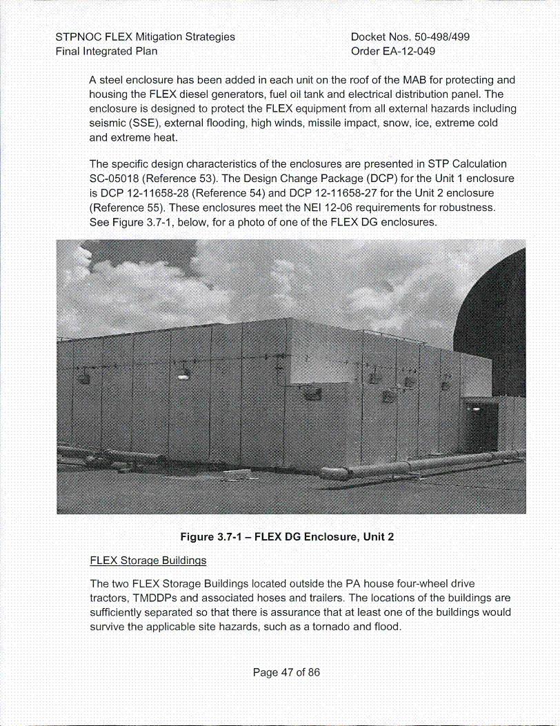
STPNOC FLEX Mitigation StrategiesFinal Integrated Plan
Docket Nos. 50-498/499Order EA-1 2-049
A steel enclosure has been added in each unit on the roof of the MAB for protecting andhousing the FLEX diesel generators, fuel oil tank and electrical distribution panel. Theenclosure is designed to protect the FLEX equipment from all external hazards includingseismic (SSE), external flooding, high winds, missile impact, snow, ice, extreme coldand extreme heat.
The specific design characteristics of the enclosures are presented in STP CalculationSC-05018 (Reference 53). The Design Change Package (DCP) for the Unit 1 enclosureis DCP 12-11658-28 (Reference 54) and DCP 12-11658-27 for the Unit 2 enclosure(Reference 55). These enclosures meet the NEI 12-06 requirements for robustness.See Figure 3.7-1, below, for a photo of one of the FLEX DG enclosures.
Figure 3.7-1 - FLEX DG Enclosure, Unit 2
FLEX StoraQe BuildinQs
The two FLEX Storage Buildings located outside the PA house four-wheel drivetractors, TMDDPs and associated hoses and trailers. The locations of the buildings aresufficiently separated so that there is assurance that at least one of the buildings wouldsurvive the applicable site hazards, such as a tornado and flood.
Page 47 of 86
STPNOC FLEX Mitigation Strategies Docket Nos. 50-498/499Final Integrated Plan Order EA-12-049
The FLEX storage building located on the MCR embankment intermediate level is apre-engineered metal building designed to meet the following:
* ASCE 7-10 for seismic capability* Design basis for wind load* High temperature - the building contains no heat load and it will be ventilated by
natural circulation* Cold temperature - addressed through use of anti-freeze in the tractors and motors
for the TMDDPs* Hazards due to tornadoes and flood are addressed by separating the buildings by
over a mile apart and locating them at different elevations
A portion of the Low Level Radwaste (LLRW) Building serves as the FLEX storagebuilding for the other set of equipment. It is a pre-engineered metal buildingdesigned to meet the following:
* ASCE 7-05 for seismic capability - seismic protection evaluated equivalent to ASCE7-10
* Design basis for wind load* High temperature - the building contains no heat load and it will be ventilated by
natural circulation* Cold temperature - addressed through use of anti-freeze in the tractors and motors
for the TMDDPs
* Hazards due to tornadoes and flood are addressed by separating the buildings byover a mile apart and locating them at different elevations
Note that the LLRW Building was built prior to the FLEX effort under ASCE 7-05, not
ASCE 7-10. An engineering review was performed to address the difference in coderequirements (ASCE 7-05 versus ASCE 7-10). The study concluded that for this area ofthe U.S. and for this particular building, the differences will not adversely affect thestructural and foundation performance (Reference 56).
Seismic Survivability of FLEX Storaqe Buildinqs
NEI 12-06 was used to establish requirements for the storage of FLEX equipment.Section 5.3.1 listed acceptable options for storage, one of which was to house theequipment in a building designed equivalent to ASCE 7-10. STP implemented thisguidance for the design and analysis of the two FLEX Storage Buildings.
Page 48 of 86
STPNOC FLEX Mitigation Strategies Docket Nos. 50-498/499Final Integrated Plan Order EA-1 2-049
The STP FLEX strategy includes storage of equipment in two non-Category 1 one-storymetal buildings located outside the Protected Area. These structures were designed orevaluated equivalent to ASCE 7-10, 'Minimum Design Loads for Buildings and OtherStructures", which is one of the acceptable methods identified in Section 5.3.1 of NEI12-06.
In response to a question to the industry from the NRC regarding seismic survivability of
the FLEX Storage Buildings, STP completed an engineering evaluation that determinedthat another load case, wind loading, governs the storage building designs such thatthey would be functional following an SSE (Reference 57).
The STP Engineering evaluation confirmed that the wind forces used in the designsignificantly exceed SSE seismic forces. This is a consequence of the relatively lowmass of the one-story buildings, the low seismicity of the Texas Gulf Coast region, andthe relatively high wind forces in this region. The engineering evaluation estimated SSEseismic forces using the static equivalent method of seismic analysis and 1.5 times SSEpeak acceleration. Therefore, even though SSE was not used in the design of thebuildings, the higher wind forces that were used guarantee that the buildings will survivethe STP design basis (SSE) earthquake.
Note also that at STP the reevaluated seismic spectra (GMRS) is lower than SSE, asestablished in STP's Seismic Hazard and Screening Report (Reference 58).
The design of the buildings for high wind loads makes them capable of withstanding thesmaller lateral forces that would occur during an earthquake characterized by SSE.Since the SSE bounds the GMRS, both buildings are confirmed to withstand both SSEand GMRS seismic loads.
3.8 Planned Deployment of FLEX Equipment
The only FLEX equipment that must be deployed into the PA are the TMDDPs andassociated hoses and trailers that are primarily used to move water to the AFWST andthe RWST. The TMDDPs will be deployed when personnel are available but is requiredwhen AFWST level lowers to less than 177,000 gal per EC00.
The TMDD pumps are pulled using four wheel drive tractors with front end loaders. Thetractors are stored with the pumps and hose trailers in the two FLEX buildings. Two
/_
haul paths are available for the tractor stored in the LLRW Building and three haul pathsare available to the tractor stored on the east side of the MCR. The front end loaderswill be used for debris removal if necessary.
Page 49 of 86
STPNOC FLEX Mitigation Strategies Docket Nos. 50-498/499Final Integrated Plan Order EA-12-049
In Phase 3, the NSRC will provide additional equipment such as pumps and generatorsto be used as needed. Both the site FLEX TMDDPs and the NSRC pumps will besituated near the water source to limit the length of the suction hose required.
3.8.1 Haul Paths
The haul paths for transporting the TMDDPs into the PA to their deployment
locations have been reviewed for potential soil liquefaction and were determinedto be stable following a seismic event. Soil liquefaction is discussed in UFSARSection 2.5.4.8.1.5, which states that liquefaction will not occur in the plant areaduring the SSE.
Additionally, the haul paths minimize travel through areas with trees, power lines
and narrow passages to the extent practical. High winds can cause debris fromdistant sources to interfere with planned haul paths, so debris removal equipment(four wheel drive tractors with front end loaders) is stored inside the FLEXStorage Buildings to clear obstructions from the pathway between the storagebuildings and their deployment location(s).
The haul paths from the FLEX Building located east of the MCR are as follows:
* Top of reservoir embankment road that heads directly to the plant from theeast
* Top of reservoir embankment road that goes around the reservoir andapproaches the plant from the west
* Down reservoir embankment to the heavy haul road
Depending on the type external event, one of these haul paths should beavailable.
Phase 3 of the FLEX strategies involves the receipt of equipment from offsitesources including the NSRC and various commodities such as fuel and supplies.Delivery of this equipment is discussed in Section 3.10 of the FIP.
The ,same debris removal equipment used for the haul paths may also be used to
support debris removal to facilitate road access within the site boundaries.
3.8.2 Accessibility
Potential access impairments consist primarily of doors in Phases I and 2 andPA access gates in Phases 2 and 3. These doors and gates are typicallycontrolled to maintain their function as barriers during normal operations.
Following a BDBEE and subsequent ELAP, FLEX coping strategies may requirethe routing of hoses and cables through normally closed barriers in order to
Page 50 of 86
STPNOC FLEX Mitigation Strategies Docket Nos. 50-498/499Final Integrated Plan Order EA-12-049
connect FLEX equipment to station water and electric systems, as well as foringress and egress and ventilation. Certain barriers (gates and doors) will beopened and remain open for the duration of the event (Reference 21). Thisdeparture from normal administrative controls is acknowledged by Security and isacceptable during the implementation of FLEX coping strategies.
The Shift Manager will distribute keys as necessary to personnel to permitopening of Security doors during an ELAP event (Reference 21).
Vehicle access to the PA occurs via the East Gafe Entrapment. As described inFSG-06, Security is contacted to open the East Gate Entrapment to allowdelivery of TMDDPs, tractors and hose trailers into the PA.
3.8.3 Deployment Limitations for the FLEX TMDDPs Due to Flooding
It is clearly stated in the UFSAR that a breach of the MCR embankment is not
considered a credible event. Many conservatisms were contained in the analysisincluding the assumption of an instantaneous removal of approximately 2000linear feet on the embankment, as stated in UFSAR Section 2.4.4.1.1.3.
In order to get a better understanding of the site conditions that would beexpected following the very unlikely event of a failure of the MCR embankment, a
more realistic breach analysis was performed in 2012 by Atkins (Reference 59).Results of this 2012 MCR embankment breach analysis were used to determineflood levels on site at various time intervals after the event.
One of the FLEX scenarios utilizes TMDDPs to pump water to the AFWST andthe RWST. The input from the 2012 breach analysis was used in developing timelines for implementing the use of the TMDDPs.
3.9 Fuelingq of Equipment
The diesel consumption for the first seven days of the BDBEE will not deplete our ESEDG FOSTs. The fuel oil that will be used for these strategies is compatible with all thevarious FLEX diesel components.
The three ESF DG FOSTs each contain at least the TS limit of 60,500 gal per unit,yielding a minimum of 181,500 gal of fuel oil per unit that is protected from externalevents. The fuel oil that STP uses for all FLEX diesel driven components will be storedin these tanks.
Each FLEX DG will use 54 gallons per hour at 75% load and 70 gallons per hour at fullload. The FLEX DG has a protected 660 gal fuel oil tank that will allow over eight hours
Page 51 of 86
STPNOC FLEX Mitigation Strategies Docket Nos. 50-498/499Final Integrated Plan Order EA-12-049
of fully loaded run time before requiring refueling. Approximately 12 hours into theevent, preparations will be underway to begin the refill effort. In each ESF DG bay,there is a 1 inch fuel oil sample line that will be used to install a suction hose fitting. Thesuction hose will be attached to a 1 20V FLEX fuel oil transfer pump stored in a FLEXlocker on the EAB 86' elevation. A discharge hose will be lowered from the roof of theEAB and attached to the fuel oil transfer pump. The hoses will also be stored in theEAB 86' elevation. Power for the pump will come from a receptacle on the 35' elevationof the EAB in the Control Room. An extension cord for connecting the receptacle to thepump is also stored in the EAB 86' elevation. These actions are described in FSG-19(Reference 32).
Refueling the TMDDPs will not be required until more than 24 hours after the start of theevent. To refuel these pumps, the hose used to fill the FLEX DG FOST will need to belowered to ground level (29 ft elevation), east of the 0GB to facilitate refueling anyportable equipment (Reference 32). When the NSRC refuel equipment arrives on site,it can also be used to move fuel from the ESF DG FOSTs to the TMDDPs.
The following fuel consumption approximations are documented in the acceptance testpackages in the applicable work orders:
* The FLEX DG uses approximately 70 gallons per hour at full load (1,680 gallons perday) J
* The TMDDPs use approximately 15 gallons per hour at full load (360 gallons per day)
Per the SAFER guideline, the two NSRC Marine turbine generators use approximately110 gals/hr each (5280 gallons per day).
Given these fuel consumption approximations, the minimum of 181,500 gallons of fuel
in the ESE DG FOSTs plus the 660 gallons of fuel in the FLEX FOST, STP will hassufficient fuel to operate under these conditions for approximately 25 days per Unit.
3.10 Offsite Resources
3.10.1 National SAFER Response Center
The industry has established two NSRCs to support utilities and providesupplemental equipment during BDB events. STP has established contracts withthe Pooled Equipment Inventory Company (PEICo) for support of the NSRCs, asrequired. Each NSRC will hold five sets of equipment, four of which will be ableto be fully deployed when requested with the fifth set of equipment in amaintenance cycle. In addition, onsite BDB equipment hose and cable end
Page 52 of 86
STPNOC FLEX Mitigation Strategies Docket Nos. 50-498/499Final Integrated Plan Order EA-12-049
fittings have been standardized to be compatible with the equipment suppliedfrom the NSRC.
In the event of a BDBEE and subsequent ELAP/LUHS condition, equipment willbe moved from an NSRC directly to the STP site staging area. In the event thatthe onsite staging area is not available, the NSRC will be directed to send theequipment to a local assembly area established by the SAFER team. These
alternate staging areas are in Bay City, approximately 30 minutes from the STPand near Wharton, approximately one hour from the STP. Equipment can betaken to the STP site from the offsite staging areas and staged at the SAFERonsite Staging Area "B" on the west side of the plant by ground or helicopter ifground transportation is unavailable.
See Figure 3.10.1-1 and Figure 3.10.1-2, below, for travel paths from the offsitestaging areas to STP.
Page 53 of 86
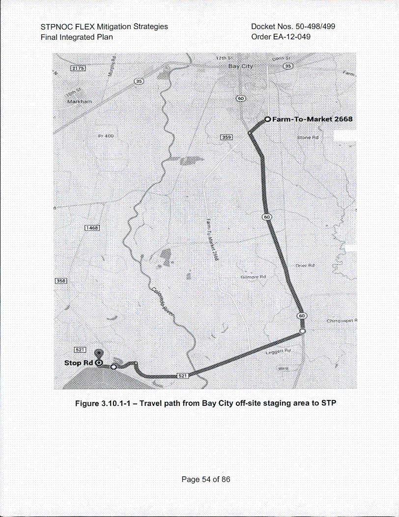
STPNOC FLEXFinal Integrated
Mitigation StrategiesPlan
Docket Nos. 50-498/499Order EA-1 2-049
4-
Figure 3.10.1-1 - Travel path from Bay City off-site staging area to STP
Page 54 of 86
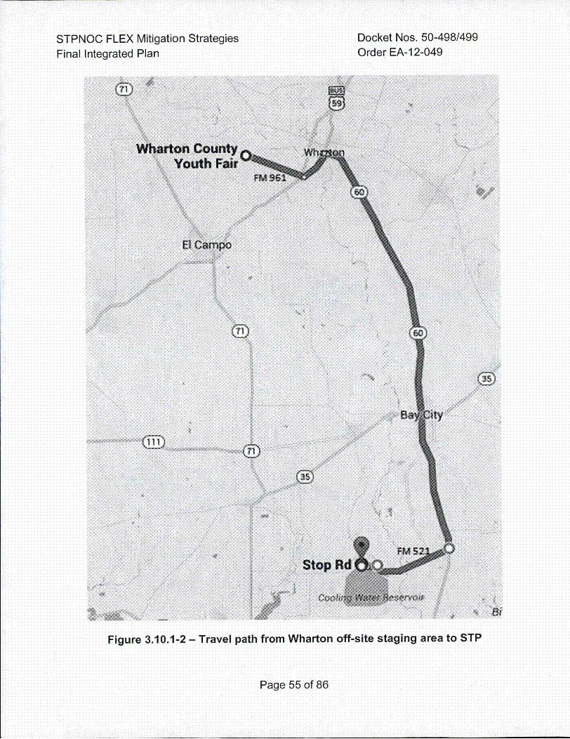
STPNOC FLEX Mitigation StrategiesFinal Integrated Plan
Docket Nos. 50-498/499Order EA-12-049
Figure 3.1 0.1-2 - Travel path from Wharton off-site staging area to STP
Page 55 of 86
STPNOC FLEX Mitigation Strategies Docket Nos. 50-498/499Final Integrated Plan Order EA-12-049
Communications will be established between STP and the SAFER team usingsatellite phones, helping required equipment to be moved to the site as needed(Reference 22). The NSRC equipment will begin to arrive on site within 24 hoursfrom the initial request.
3.10.2 Equipment List
The equipment stored and maintained at the NSRC for transportation to the localassembly area to support the response to a BDB external event at STP is listedin Table 3.10.2-1, below. Table 3.10.2-1 identifies some of the equipment thatwill be available for backup and replacement purposes should onsite equipmentbe unavailable. Only the 4160 VAC generator is credited in the FLEX strategies(Reference 19). Emergency response personnel can use the backup equipmentas needed to enhance implementation.
Page 56 of 86
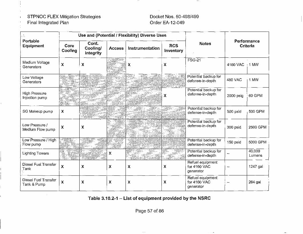
STPNOC FLEX Mitigation StrategiesFinal Integrated Plan
Docket Nos. 50-498/499Order EA-12-049
~Use and (Potential / Flexibility) Diverse Uses
Portable Cn.NtsPerformanceEquipment Core on.RCS NtsCriteria
Cooling Cooling/ Access Instrumentation Inventoryintegrity
Medium Voltage FSG-2......Generators.. X X X X 4160 VAC 1 MW
Low Voltage Potential.....backup... for.
............. Potential backup forHigh.Pressur =:''':=" ....... ............ "defense-in-depth 2000 psig 60 GMW
SG Makeup pump X > defense-in-depthX 5000 psid 500 GPMHighPresurePotential backup for
Lo P e su e • ::: : 2i: ...... .. : ""... .......... defense-in-depth30 psd 2 0GPMnedtiumFow pump ;==,,: = ; ) "•
Low..... Pressure! High : •!!!: ::::•,:••Potential backup for 15psd 00GPFlowkeu pump X ... defense-in-depth 50pi 0 P
Lighting Towers •IPotential backup for 4,0
•; defense-in-depth Lu sd 50Gmen
Di PeselsueTraser/ X X Refuelquipmen
Diesel Fuel Transfer Refuel equipment
Tank & Pump XXX Xfor 4160 VAC -- 264 galgenerator
Table 3.10.2-1 - List of equipment provided by the NSRC
Page 57 of 86
STPNOC FLEX Mitigation Strategies Docket Nos. 50-498/499Final Integrated Plan Order EA-12-049
3.11 Eqiuipment Operatin~q Conditions
3.11.1 Ventilation and Habitability
Some plant locations where FLEX equipment is stored have heat loads and little
to no ventilation until the FLEX DGs are put into operation and begin poweringequipment. Natural circulation and the proceduralized propping open of doorsare the initial capabilities for room cooling. There will be no forced ventilationanywhere in the plant until the FLEX OG is powering equipment. STP performedevaluations on the most critical areas and equipment to ensure equipmentsurvivability and area habitability.
The EAB Heatup Calculation NA1-1646-001 (Reference 47) with supporting inputcalculation NC-07091 (Reference 93) evaluates ELAP heatup in critical portionsof the EAB, primarily the QDPS and inverter rooms.
Heatup calculations for the QDPS cabinets and the Class 1 E inverters show thatprior to 24 hours into the event the room doors will need to be opened forventilation. After opening the room doors, the cabinets and inverters will notreach their high temperature limit for an additional three days at which pointforced ventilation will have been established.
STP's calculations demonstrate that running the TDAFW pump during an ELAPevent will not cause the TDAFW pump room to heat up beyond the pumpEnvironmental Qualification temperature limit of 170°F (Reference 60). However,operators will be directed to the IVC early in the event to lineup AuxiliaryFeedwater to all S~s. FSG-05 directs operators to open the door to the TDAFWpump room to allow the heat being generated in the room to dissipate into thehallway, up the stairwell and out of the IVC. Once the FLEX DG is in operation,the TDAFW Cubicle Vent fan can also be started. The FLEX SO makeup pumpsin the IVC bays also have cubicle vent fans that can be started when the FLEXDO is powering DPI1000, which provides power to the cubicle vent fan MCC(Reference 22).
The rooms containing the-SG PORVs and the TDAFW pump are at elevatedtemperatures. STP has cool vests stored inside a FLEX storage locker in theEAB on the 86' elevation for personnel use in these rooms and for other FLEXstrategies, if necessary.
Additionally, as part of STP's loss of EAB HVAC Procedure (Reference 61 ),portable ventilation fans are pre-staged in the EAB on the 10', 60' and 86'
elevations to be used if ventilation is lost. The loss of EAB HVAC procedure also
:.i....... _Page 58 o~f 86
STPNOC FLEX Mitigation Strategies Docket Nos. 50-498/499Final Integrated Plan Order EA-12-049
directs the placement of these fans and identifies which doors to prop open forbest circulation of air (Reference 61).
During an ELAP, Control Room ventilation will be lost, however, the ControlRoom heat loads will be simultaneously reduced. The DC load shedding actionscompleted during the first two hours of the event per FSG-04 (Reference 30) de-
energizes equipment in the Control Room and the adjacent relay room. Theremaining heat sources in the Control Room are primarily generated bypersonnel, emergency lighting, and remaining QDPS instrumentation. Althoughthe ELAP heat-up calculation performed by STP (References 47) does notspecifically model heat-up in the Control Room, the calculations show thattemperature response in the critical rooms is relatively slow, requiring over 24hours before temperature limits are approached and action is taken to opendoors. The calculation models the Control Room as an adjacent heat sink andassumes Control Room temperature starts at 78°F and increases linearly overthe next eight hours to I104°F. This is a reasonable assumption based on thelimited heat sources remaining in the Control Room and its relatively large airvolume (approximately 91,000 ft3).
The FLEX DG is projected to be started three hours following the start of theELAP event. Actions to connect cables to MCC EIA2(E2A2) are projected tostart between 30 and 90 minutes following event start. After MCCs E1A2(E2A2)and E1C2(E2C2) are energized, communications equipment, lighting, andbattery chargers are energized via the FLEX DG and the safety-related ControlRoom Return Fan 11IA(21A) may be started per FSG-05 (Reference 22). Actions
to connect cables to MCC El1B4(E2B4) are projected to be performed before 4.5hours following event start. An additional Control Room Return Fan 11 B(21 B)can then be started to increase outside air flow to the Control Room.
3.11.2 Heat Tracing
Heat trace circuits keep the 4-weight-percent boric acid at approximately
85°F. When the ELAP occurs, the water temperature will slowly lower but will notdecrease past 55°F because the tanks and piping are insulated and insideconcrete buildings. When the FLEX DG is running, the Boric Acid pumps will bestarted when the boric acid piping temperature is less than 65 degrees F. Thepumps recirculate the solution in the BATs to ensure the temperature does notcontinue to lower to the point where boric acid begins to solidify. In the unlikelyevent that the boric acid begins to solidify early, suction source transfer from theBATs to the RWST can be started per FSG-08 or FSG.-01 (References 33 and62).
.Page.5.9 of 86 .
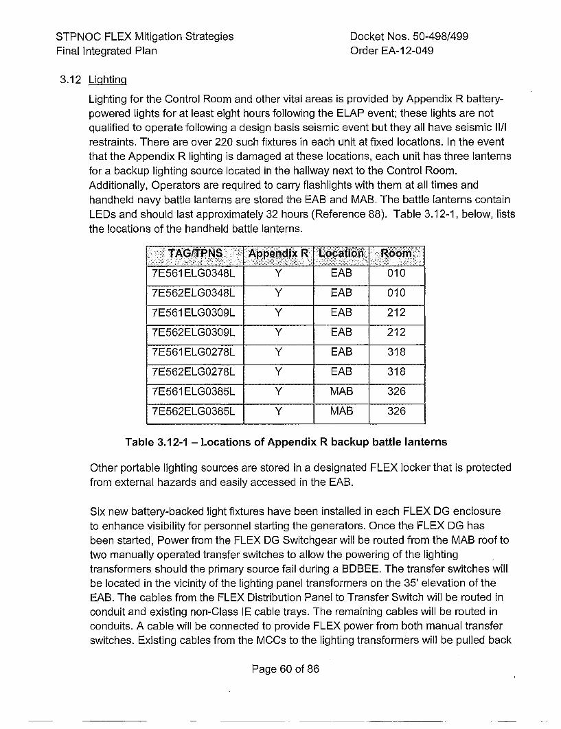
STPNOC FLEX Mitigation Strategies Docket Nos. 50-498/499Final Integrated Plan Order EA-12-049
3.12 LiQhtincj
Lighting for the Control Room and other vital areas is provided by Appendix R battery-powered lights for at least eight hours following the ELAP event; these lights are notqualified to operate following a design basis seismic event but they all have seismic Il/Irestraints. There are over 220 such fixtures in each unit at fixed locations. In the eventthat the Appendix R lighting is damaged at these locations, each unit has three lanternsfor a backup lighting source located in the hallway next to the Control Room.Additionally, Operators are required to carry flashlights with them at all times andhandheld navy battle lanterns are stored the EAB and MAB. The battle lanterns containLEDs and should last approximately 32 hours (Reference 88). Table 3.12-1, below, liststhe locations of the hand held battle lanterns.
: TA•GIPNS :==lAppendix R! !Location Roo
7E561ELG0348L Y EAB 010
7E562ELG0348L Y EAB 010
7E561ELG0309L Y EAB 212
7E562ELG0309L Y EAB 212
7E561ELG0278L Y EAB 318
7E562ELG0278L Y EAB 318
7E561 ELG0385L Y MAB 326
7E562ELG0385L Y MAB 326
Table 3.12-1 - Locations of Appendix R backup battle lanterns
Other portable lighting sources are stored in a designated FLEX locker that is protected
from external hazards and easily accessed in the EAB.
Six new battery-backed light fixtures have been installed in each FLEX DG enclosureto enhance visibility for personnel starting the generators. Once the FLEX DG hasbeen started, Power from the FLEX DG Switchgear will be routed from the MAB roof totwo manually operated transfer switches to allow the powering of the lightingtransformers should the primary source fail during a BDBEE. The transfer switches willbe located in the vicinity of the lighting panel transformers on the 35' elevation of theEAB. The cables from the FLEX Distribution Panel to Transfer Switch will be routed inconduit and existing non-Class IE cable trays. The remaining cables will be routed inconduits. A cable will be connected to provide FLEX power from both manual transferswitches. Existing cables from the MCCs to the lighting transformers will be pulled back
Page 60 of 86
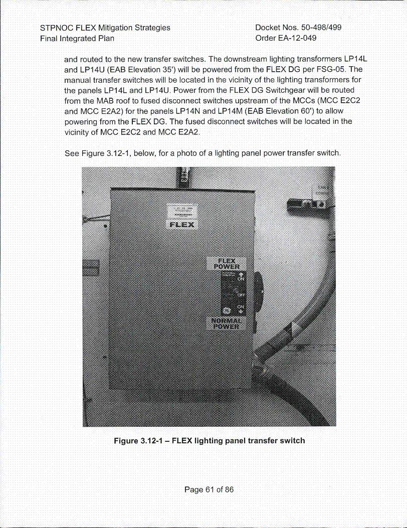
STPNOC FLEX Mitigation Strategies Docket Nos. 50-498/499Final Integrated Plan Order EA-1 2-049
and routed to the new transfer switches. The downstream lighting transformers LP1 4Land LP14U (EAB Elevation 35') will be powered from the FLEX DG per FSG-05. Themanual transfer switches will be located in the vicinity of the lighting transformers forthe panels LPI4L and LP14U. Power from the FLEX DG Switchgear will be routedfrom the MAB roof to fused disconnect switches upstream of the MO~s (MCC E2C2and MOO E2A2) for the panels LP14N and LP14M (EAB Elevation 60') to allowpowering from the FLEX DG. The fused disconnect switches will be located in thevicinity of MOO E2O2 and MOO E2A2.
See Figure 3.12-1, below, for a photo of a lighting panel power transfer switch.
Figure 3.12-1 - FLEX lighting panel transfer switch
Page 61 of 86
STPNOC FLEX Mitigation Strategies Docket Nos. 50-498/499Final Integrated Plan Order EA-12-049
There are numerous 120 VAC receptacles that will also be powered by the FLEX 0G.At this point, Appendix R fixtures, those are fed from aforementioned lighting panels,throughout all elevations of the EAB will be re-powered and returned back tocharge/standby mode. DCP 12-11685-34 and 12-11685-80 provide FLEX power tothese lighting panels (Reference 63). LPE-14L provides over twenty 120 VAC powerreceptacle circuits for the Control Room and also a number in rooms surrounding thecontrol room, such as such the kitchen area and briefing areas in EAB. LPE-14Uprovides power to a large number of Exit signs in EAB and to a large number of
Appendix R light receptacles. LPE-14M and 14N provide lighting in Main Control Roomand EAB switchgear rooms, hall wall and Inverter/Battery rooms for all Trains.
In Phase 3, the NSRC will bring light towers to STP which can be placed around the
site as needed.
3.13 Communications
As a result of the Recommendation 9.3 Communications Assessment (References 64
and 98), communications at STP were upgraded as follows:
* Additional sound powered head sets and cords* Additional hand-held satellite phones and chargers
* Additional radios and chargers
* Bullhorns`* Replacement antennas for the hardwired satellite phones.* Modifications were made to enable the hardwired satellite phone in the Technical
Support Center (TSC) to be moved into the Main Control Room (CR) during theELAP event thereby providing two hardwired satellite phones in the CR.
* Storage of this equipment is inside the power block, protected from external events.These communication strategies are discussed in FSG-05, Initial Assessment and
FLEX Equipment Staging.
In addition, the Lossy Loop amplification system can now be powered by FLEX powerthus enabling radio communications throughout the plant including inside buildings ontwo channels.
Phase 1
STP plant communications capabilities include multiple technologies and redundantpower supplies. In the event of massive system failures, onsite and offsitecommunication requirements will continue to be met with the combination of sound
Page 62 of 86
STPNOC FLEX Mitigation Strategies Docket Nos. 50-498/499Final Integrated Plan Order EA-12-049
powered phones, satellite phones, and radios that will work in line of sight. The soundpowered phones are staged throughout the plant inside the power block.
There is one hardwired satellite phone in each Control Room and one in each TSCwith hard wired antennas on the roof of the EAB. Per FSG-05, the hard wired satellitephone normally located in the TSC will be moved into the Control Room following aBDBEE (Reference 22). For the permanent satellite phone in the Control Room andthe TSC, replacement antennas are stored in protected locations in the EAB in theevent that both installed antennas are damaged during the event. There are also twoadditional hand held satellite phones in the EAB 35' elevation to be used as necessary.During Phase 1, sufficient batteries are available to power plant radios and satellitephones until the FLEX 480V DG is available to supply power to the radio and phonechargers.
Phase 2
Once the FLEX DG has been started and begins providing power to lighting panels
LPE-14M and LPE-14N, the Lossy Loop Amplifiers will be receiving power. Until theLossy Loop is powered, the radios will only work for line-of-sight communications. Tworadio channels have been modified so that they will function once the Lossy Loop ispowered - One channel is designated for use by Security and the other channel isdesignated for Operations and Maintenance. The Control Room operators will bring ahand-held radio into the Control Room to use during the event since the Quintronsystem is without power. Each unit has also been provided with a bull horn stored inthe FLEX storage lockers to assist with public address-type communications.
3.14 Shutdown and Refuelinq Modes Analysis
The units will be at full power for the majority of any operating cycle, which is the mostlimiting condition for scenarios in which the SGs are available for core heat removal.The same general FLEX approaches can also be used at reduced power and in lowermodes when the SGs are intact (Modes 1-4). At reduced power, the plant thermalresponse will be slower and less severe. In lower-power modes, the additional time forthe RCS to heat up to the point at which decay heat can be removed by the SG PORVswill not invalidate or challenge the overall FLEX strategies.
FLEX strategies are not explicitly designed for outage conditions due to the smallfraction of the operating cycle that is spent in an outage condition, generally less than10%. Requirements for FLEX strategies in outage conditions are described in a NEIposition paper (Reference 65) which was subsequently endorsed by the NRC(Reference 66). Due in part to the large and diverse scope of activities andconfigurations for any given nuclear plant outage (planned or forced), the paper
Page 63 of 86
STPNOC FLEX Mitigation Strategies Docket Nos. 50-498/499Final Integrated Plan Order EA-12-049
concluded that a systematic approach to shutdown safety risk identification andplanning is the most effective way of enhancing safety during shutdown. The NEI
•position references concepts established for outage planning and control includingintegrated management, level of activities, defense-in-depth, contingency planning,training, and outage safety review. In particular:
* Contingency plans should be available when entering a higher risk evolution.* Contingency plans should be developed when system availability drops below
planned defense in depth.* Contingency plans should consider use of alternate equipment to respond to loss of
dedicated safety and monitoring equipment, and should consider additionalmonitoring or controls to minimize the potential for unplanned equipmentunavailability.
* Personnel who may be required to implement a contingency plan should be familiar
with the plan.
3.14.1 Core Coolinq and RCS Inventory Control
With no SGs available, RCS water will begin to evaporate as a means to transfercore decay heat to the containment. The primary, N, strategy for RCS makeup isto pump water from the RWST by aligning a FLEX Shutdown RCS makeup pump(170 gpm at 100 psig) to take suction from the RWST and discharge to an RCScold leg. The FLEX Shutdown RCS makeup pumps are located in the SI bays onthe -29 ft elevation of the FHB. The alternate, N+I, strategy is identical to theprimary except that the pump and connection points are located in a different SIbay and train and connects to different SI piping. The N pump and connectionsare located in the A-Train SI bay, and the N+1 pump and connections are locatedin the B-Train SI bay.
For this shutdown mode FLEX strategy, the reactor is assumed to have beenshut down below Mode 3 for a minimum of 30 hours following an operating cyclewhich represents the approximate minimum time required to cooldown the plantfor normal offload of spent fuel with the SGs isolated for planned maintenance.Additionally, both the RCS and the Containment are assumed to be ventedbecause they are vented the majority of the time during Modes 5 and 6. Makeuprequirements in this time frame are approximately 143 gpm (Reference 67) whichcan be supplied by one of the FLEX ROS makeup Pumps. The 170 gpm at 100psig FLEX ROS makeup pump will provide the required 143 gpm plus anadditional 27 gpm for boron flushing as required by NEI 12-06.
Page 64 of 86
STPNOC FLEX Mitigation Strategies Docket Nos. 50-498/499Final Integrated Plan Order EA-12-049
3.14.2 SFP Strateqy
During shutdown and refueling operations, the time to reach 200° F and the heat-up rate of the SFP as a function of time following a loss of SFP cooling areprovided in the Plant Curve Book Figures 5.19B and 5.13B, respectively, for eachUnit. The maximum heat load for a typical refueling operation occurs at the endof a full core offload, typically greater than seven days after the reactorshutdown. Assuming this full core heat load at seven days coincident with a lossof cooling, the SFP would begin to boil approximately five hours following theELAP/LUHS event.
In this scenario the SFP boil-off rate would be about 93 gpm, well within themakeup capability of the RMW pump (300 gpm) and FLEX SFP makeup pump(250 gpm). The SFP would boil down from the normal operating level to 10 feetabove the top of the active fuel in approximately 33 hours following the loss ofcooling (Reference 46). Maintaining the water level greater than 10 feet above
the active core should limit the maximum radiation dose to 2.5 millirem per hourfor personnel (Reference 102).
3.14.3 Containment Strateqy
With no SGs available, once through cooling will be used to transfer core decayheat to the containment. Without containment heat removal systems available,containment pressure and temperature will rise. Containment venting may berequired to prevent exceeding the containment pressure limit. During Phases 2and 3, containment will be vented as necessary using FSG-12 (Reference 48).
Containment is usually vented during outages, but in the event it was not vented,the actual strength of the containment is considerably higher than theconservatively chosen static design pressure of 56.5 psig stated in Section3.8.1.3.1 of the UFSAR (Reference 44). Per ASME Code, the STP containmentswere physically tested to 115% of design pressure (65 psig) and the calculatedultimate strength is 141 psig (Reference 89).
Page 65 of 86
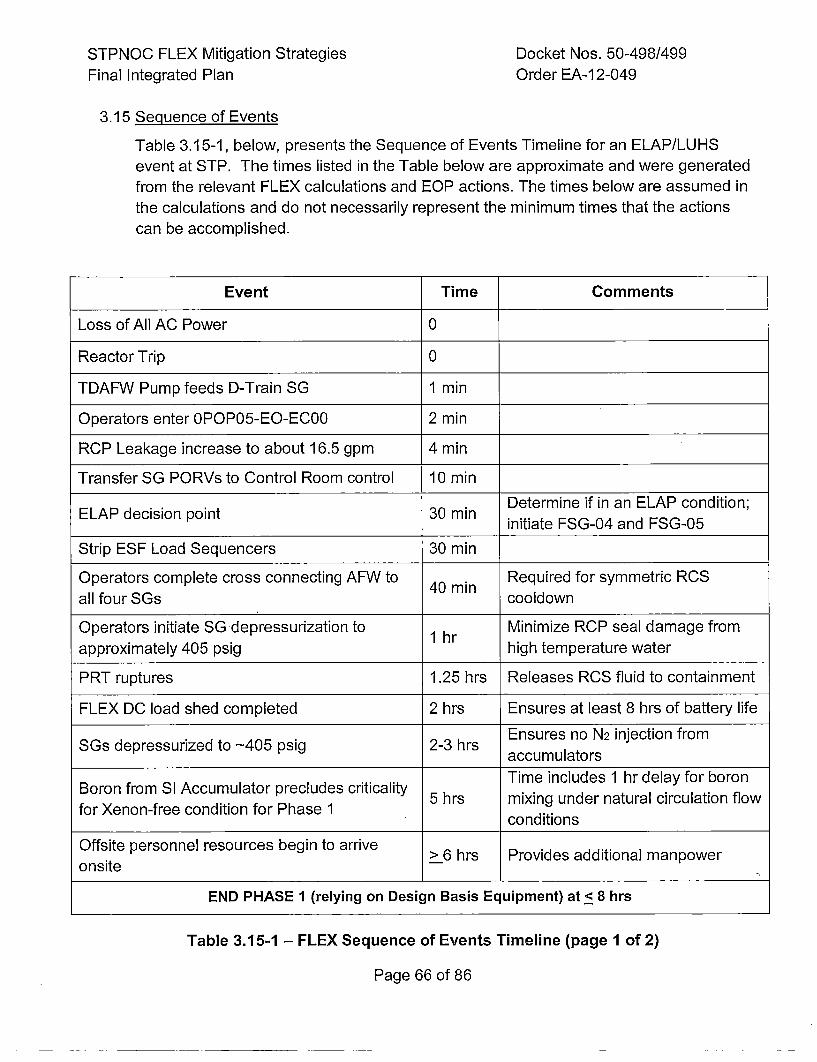
STPNOC FLEX Mitigation StrategiesFinal Integrated Plan
Docket Nos. 50-498/499Order EA-12-049
3.15 Sequence of EventsTable 3.15-1, below, presents the Sequence of Events Timeline for an ELAP/LUHSevent at STP. The times listed in the Table below are approximate and were generatedfrom the relevant FLEX calculations and EOP actions. The times below are assumed inthe calculations and do not necessarily represent the minimum times that the actionscan be accomplished.
Event Time Comments
Loss of All AC Power 0
Reactor Trip 0
TDAFW Pump feeds D-Train SG 1 min
Operators enter 0POP05-EO-EC00 2 min
RCP Leakage increase to about 16.5 gpm 4 min
Transfer SG PORVs to Control Room control 10 min
ELAPdeciion oint30mm Determine if in an ELAP condition;initiate FSG-04 and FSG-05
Strip ESF Load Sequencers 30 min
Operators complete cross connecting AFW to 40mn Required for symmetric RCS
all four SGs 4mm cooldown
Operators initiate SG depressurization to 1 r Minimize RCP seal damage from
approximately 405 psig 1 r high temperature water
PRT ruptures 1.25 hrs Releases RCS fluid to containment
FLEX DC load shed completed 2 hrs Ensures at least 8 hrs of battery life
Ensures no N2 injection fromSGs depressurized to -405 psig 2-3 hrs acmltr
Time includes 1 hr delay for boronBoron from SI Accumulator precludes criticality 5 hrs mixing under natural circulation flowfor Xenon-free condition for Phase 1 conditions
Offsite personnel resources begin to arriveonste> 6 hrs Provides additional manpower
END PHASE 1 (relying on Design Basis Equipment) at_< 8 hrs
Table 3.15-1 - FLEX Sequence of Events Timeline (page 1 of 2)
Page 66 of 86
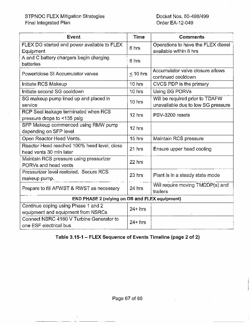
STPNOC FLEX Mitigation StrategiesFinal Integrated Plan
Docket Nos. 50-498/499Order EA-12-049
Event Time Comments
FLEX DG started and power available to FLEX Operations to have the FLEX dieselEquipment 8Bhrs available within 8 hrs
A and C battery chargers begin charging 8 hrsbatteries
Accumulator valve closure allowsPower/close SI Accumulator valves < 10 hrs cniudcodw
Initiate RCS Makeup 10 hrs CVCS PDP is the primary
Initiate second SG cooldown 10 hrs Using SG PORVs
SG makeup pump lined up and placed in 10 hrs Will be required prior to TDAFWservice unavailable due to low SG pressureRCP Seal leakage terminated when RCS 1 r S-20rstpressure drops to <135 psig ____
SFP Makeup commenced using RMW pump 12 hrsdepending on SFP level
Open Reactor Head Vents. 15 hrs Maintain RCS pressure
Reactor Head reached 100% head level, close 2 r nueuprha olnhead vents 30 min laterMaintain RCS pressure using pressurizer 2 rPORVs and head ventsPressurizer level restored. Secure RCS 2 r ln si taysaemdmakeup pump.
Will require moving TMDDP(s) andPrepare to fill AFWST & RWST as necessary 24 hrs talr
END PHASE 2 (relying on DB and FLEX equipment)
Continue coping using Phase 1 and 2equipment and equipment from NSRCs24hrConnect NSRC 4160 V Turbine Generator to 24hrone ESF electrical bus 24+________hrs_____
Table 3.15-1 - FLEX Sequence of Events Timeline (page 2 of 2)
Page 67 of 86
STPNOC FLEX Mitigation Strategies Docket{ Nos. 50-498/499Final Integrated Plan Order EA-12-049
3.16 Programmatic Elements
3.16.1 Overall Program Document
STP developed an overall program document that provides a historicaldescription of the FLEX Program (Reference 68). The revised FLEX strategiesand information are contained in this FIP.
The program elements provided in the Program Document include:
* Description-of the FLEX strategies and basis,• Provisions for documentation of the historical record of previous strategies
and the basis for changes,* The basis for the maintenance and testing programs chosen for the FLEX
equipment, and• Designation of the minimum set of parameters necessary to support strategy
implementation.
Existing design control procedures have been revised to ensure that futurechanges to the plant design, physical plant layout, roads, buildings, andmiscellaneous structures will not adversely impact the approved FLEX strategies.STP's procedure for making design changes has been updated to includescreening for impacts to FLEX strategies. As stated in the procedure, all changesaffecting the SSCs listed below must be evaluated to ensure that they do not
affect any of the FLEX strategies and associated time estimates to complete thestrategies (Reference 90):
•,Fukushima Response (FR) system or components
* Normal travel paths inside the, power block
* Vehicle travel paths inside the PA* TSC or Control Room communications (radio or satellite phone)* Instrumentation shown on QDPS
* SFP level indicators* FLEX equipment in Building 44 or the Fukushima Response Building
• SAFER laydown area on the West side of the plant
Future changes to the FLEX strategies may be made without prior NRC approvalprovided the revised FLEX strategies meet the requirements of NEI 12-06 andan engineering basis is documented that ensures that the change in FLEXstrategies continues to ensure the key safety functions (core cooling, SFPcooling and containment integrity) are met.
Page 68 of 86
STPNOC FLEX Mitigation Strategies Docket Nos. 50-498/499Final Integrated Plan Order EA-12-049
3.16.2 Procedural Guidance
The FSGs provide guidance that can be employed for a variety of conditions.Clear criteria for entry into FSGs ensures that FLEX strategies are used only asdirected for BDBEE conditions and are not used inappropriately in lieu of existingprocedures. When FLEX equipment is needed to supplement EOPs or abnormaloperating procedures (AOP), the EOP or AOP directs the entry into and exit fromthe appropriate FSG procedure. FSGs are used to supplement, not replace, theexisting procedure structure that establishes command and control for the event.
The STP FSGs were developed in accordance with PWROG guidelines.
Procedural interfaces have been incorporated into station procedure EC00 toinclude appropriate reference to FSGs and provide command and control for the
.:ELAP (Reference 11). Additionally, a new AOP for loss of all AC power while onshutdown cooling (Reference 69) was prepared to provide the command andcontrol function for the ELAP while on RHR since EC00 does not apply in thisoperating mode.
In accordance with site administrative procedures, Revision 1 of NEI 96-07
(Reference 70), Guidelines for 10 CFR 50.59 Implementation, and Revision 1 ofNEI 97-04 (Reference 71), Design Bases Program Guidelines, are used toevaluate changes to current procedures, including the FSGs, to determine theneed for prior NRC approval. However, per the guidance and examples providedin NEI 96-07, Revision 1, changes to procedures (EOPs, AOPs, or FSGs) thatperform actions in response to an event that exceeds a site's design-basis should
screen out under 10 CFR.50.59 and would not require prior NRC approval.Therefore, procedure steps which recognize the BDB ELAP/LUHS has occurredand which direct FLEX strategy actions to ensure core cooling, containment, orSFP cooling should not require prior NRC approval.
•FSGs have been reviewed and validated to the extent necessary to ensure thatimplementation of the associated FLEX strategy is feasible. Specific FSGvalidation was accomplished via walk-throughs of the guidelines whenappropriate, in accordance with 0PGP03-ZO-FLEX, "FLEX Support GuidelineProgram" (Reference 72). Revisions to the FSGs will be made in accordancewith the FLEX Support Guideline Program.
The EOPs have been revised in accordance with established EOP changeprocesses to clearly reference and identify appropriate entry and exit conditionsfor these pre-planned strategies.- The EOPs retain overall command and controlof the actions responding to a BDB external event.
Page 69 of 86
STPNOC FLEX Mitigation Strategies Docket Nos. 50-498/499Final Integrated Plan Order EA-12-049
3.16.3 Staffingq
In December 2011, the NRC added paragraph A.9 to Section IV of 10 CER 50,
Appendix E requiring Licensees to perform a detailed analysis demonstrating thaton-shift personnel assigned emergency plan implementation functions are notassigned responsibilities that would prevent the timely performance of theirassigned function as specified in the emergency plan (Reference 73). NEI 10-05(Reference 74) provides guidance for completing this analysis. However, NEI10-05 did not consider a multi-unit BDBEE with an ELAP.
In response to NTTF Recommendation 9.3, the NRC requested th'at licenseesassess their current staffing levels and determine the appropriate staff to fill allnecessary positions for responding to a multi-unit event during a BDBEE when all
units are affected, there is an ELAP, and access to the site is impeded(Reference 94).
Using the methodology presented in NEI 12-01, "Guideline for Assessing BeyondDesign Basis Accident Response Staffing and Communications Capabilities"(Reference 75), STP performed assessments of the capability of STP's on-shiftstaff and augmented Emergency Response Organization (ERO) to respond to aBDBEE.
The assumptions for the NEI 12-01 scenario postulate that the BDB event
involves a non-specific large-scale external event that results in an ELAP andLUHS that impacts both units on the site. Additionally, the NEI 12-01 guidanceassumes that access to the site by offsite responders and resources is impededas follows:
* 0 to 6 hours post event - No site access
*6 to 24 hours post event - Limited site access. Individuals may access thesite by walking, personal vehicle, or via alternate transportation capabilities(e.g., private resource providers or public sector support)
* Greater than 24 hours post event - Improved site access. Site access isrestored to a near-normal status and/or augmented transportation resources
are available to deliver equipment, supplies and large numbers of personnel
STP performed a "Phase 1" staffing study to evaluate the ability to respond to a
BDBEE using pre-FLEX station procedures and resources. STP also performeda "Phase 2" staffing study to evaluate the ability to respond to a BDBEE usingFLEX procedures and equipment. "Phase 1" and "Phase 2" as used in thissection, are not to be confused with the phase designations used in the FLEXstrategies.
Page 70 of 86
STPNOC FLEX Mitigation Strategies Docket Nos. 50-498/499Final Integrated Plan Order EA-12-049
The "Phase 1" staffing study revealed some areas for improvement in theEmergency Response Organization staffing that have been addressed(References 76 and 99).
The "Phase 2" staffing study that included staffing for FLEX strategies assessedwhether or not the FLEX strategies could be performed in the required time withthe current STP on-shift staffing. The "Phase 2" study concluded that STP'scurrent on-shift staffing can implement actions required to support the FLEXstrategies for the first six hours of the event (Reference 77). The assessmentwas verified following the completion of the FSGs and a supplement to theoriginal staffing study "Phase 2" assessment was submitted to the NRC(Reference 78).
3.16.4 Traininq
STP's Nuclear Training Program has been revised to assure personnelproficiency in utilizing FSGs and associated BDB equipment for the mitigation ofBDBEEs is adequate and maintained. These programs and controls weredeveloped and have been implemented in accordance with the SystematicApproach to Training (SAT) Process.
Initial training has been provided and periodic training will be provided to siteemergency response leaders on BDB emergency response strategies andimplementing guidelines. Personnel assigned to direct the execution of the FLEXmitigation strategies for BDB external events have received the necessarytraining to ensure familiarity with the associated tasks, considering available jobaids, instructions, and mitigation strategy time constraints.
As stated in Section 11.6 of NEI 12-06, ANSI/ANS 3.5 (Reference 79)certification of simulator fidelity is considered to be sufficient for the initial stagesof the BDBEE scenario until the current capability of the simulator model isexceeded.
Per Section 11.6 of NEI 12-06, where appropriate, integrated FLEX drills will beorganized on a team or crew basis and conducted periodically with all time-sensitive actions to be evaluated over a period of not more than eight years. It isnot required to connect or operate equipment during these drills (Reference 9).STP plans to follow the industry guidance provided in NEI 13-06 for conductingFLEX drills (Reference 103).
3.16.5 Equipment List
The equipment stored and maintained at STP for use with FLEX strategies inresponse to a BDBEE is listed in Table 3.16.5-1, below. Table 3.16.5-1 identifies
Page 71 of 86
STPNOC FLEX Mitigation StrategiesFinal Integrated Plan
Docket Nos. 50-498/499Order EA-12-049
the quantity, applicable strategy, capacity/rating and various clarifying notes forthe major BDB equipment components only.
Page 72 of 86
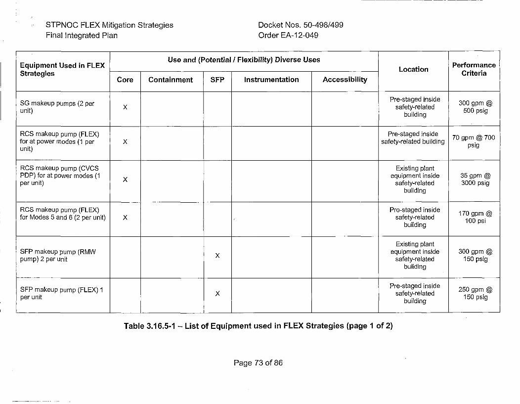
STPNOC FLEX Mitigation StrategiesFinal Integrated Plan
Docket Nos. 50-498/499Order EA-12-049
Use and (Potential / Flexibility) Diverse UsesEquipment Used in FLEX LoainPerformanceStrategies LoainCriteria
Core Containment SFP Instrumentation Accessibility
SG makeup pumps (2 per Pesadinde 300 gpm @unit) X safety-related 500 psig
building
RCS makeup pump (FLEX) Pre-staged inside 7 p 0for at power modes (1 per x safety-related building piunit) pi
RCS makeup pump (CVCS Existing plantPDP) for at power modes (1 Xequipment inside 35 gpm @per unit) safety-related 3000 psig
building
RCS makeup pump (FLEX) Pre-staged inside 170 gpm @for Modes 5 and 6 (2 per unit) X ,safety-related 100 psi
building
Existing plantSEP makeup pump (RMW Xequipment inside 300 gpm @pump) 2 per unit safety-related 150 psig
building
SEP makeup pump (FLEX) 1 Pre-staged inside 250 gpm @per unit X safety-related 150 psig
building
Table 3.16.5-1 - List of Equipment used in FLEX Strategies (page 1 of 2)
Page 73 of 86
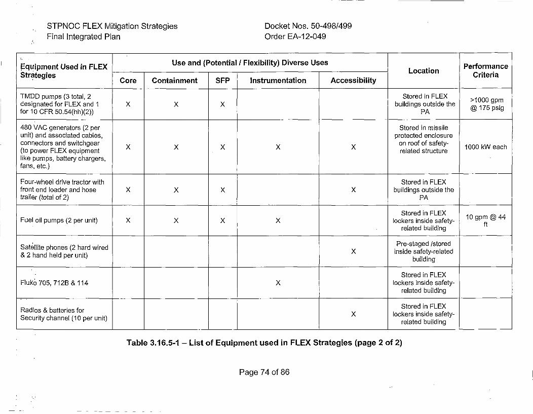
STPNOC FLEX Mitigation StrategiesFinal Integrated Plan
Docket Nos. 50-498/499Order EA-12-049
?Equipment Used in FLEX Use and (Potential / Flexibility) Diverse Uses PerformanceStratgiesLocation Ciei
StaeisCore Containment SFP Instrumentation Accessibility Ciei
TMDD pumps (3 total, 2 Stored in FLEX >1000 gpmdesignated for FLEX and 1 X X X buildings outside the @15pifor 10 CFR 50.54(hh)(2)) PA @15pi
480 VAC generators (2 per Stored in missileunit) and associated cables, protected enclosureconnectors and switchgear XXXXXon roof of safety- 1000 kW each(to power FLEX equipment related structurelike pumps, battery chargers,fans, etc.)
Four-wheel drive tractor with Stored in FLEXfront end loader and hose X X X X buildings outside thetrailer (total of 2) PA
Stored in FLEXFuel oil pumps (2 per unit) X X X X lockers inside safety- 10gmt4
related building f
Satelit phoes 2 had wredPre-staged /stored&Sandteldt phoes2hrd unit) d X inside safety-related
& 2 and eld er uit)building
Stored in FLEXFluke 705, 712B & 114 X lockers inside safety-
related building
Radis & attriesforStored in FLEXRaisecu attritchnel (1oprunt X lockers inside safety-
Secuitychanel 10 pr uit)related building
Table 3.16.5-1 - List of Equipment used in FLEX Strategies (page 2 of 2)
Page 74 of 86
STPNOC FLEX Mitigation Strategies Docket Nos. 50-498/499Final Integrated Plan Order EA-12-049
3.16.6 N+l Equipment Requirement
NEI 12-06 requires sites to have N+1 sets of major BDB equipment that directlyperforms a FLEX mitigation strategy for core cooling, containment, or SFPcooling in order to assure reliability and availability of the FLEX equipmentrequired to meet the FLEX strategies. Unit I and Unit 2 at STP are separated byover 600 feet and a significant external event is a large flood event, STP electedto provide N+1 equipment sets for each unit. Sufficient equipment has beenpurchased to address all functions at all units on-site, plus one additional spareper unit.
The N+1 capability applies to the portable FLEX equipment that directly supportsmaintenance of the key safety functions identified in Table 3-2 of NEI 12-06 forFLEX baseline capability for PWRs. Other FLEX support equipment provided formitigation of BDB external events but not directly.supporting a credited FLEXstrategy, is not required to have N+1 capability.
In the case of hoses and cables associated with FLEX equipment required forFLEX strategies, an alternate approach to meet the N+I capability has beenselected. These hoses and cables are passive components being stored in aprotected facility. It is postulated the most probable cause for.degradation/damage of these components would occur during deployment of theequipment. Therefore the +1 capability is accomplished by having sufficienthoses and cables to satisfy the N capability + 10% spares or at least 1 length ofhose and cable. This 10% margin capability ensures that failure of any one ofthese passive components would not prevent the successful deployment of aFLEX strategy. The hoses and cables that come under this requirement at STPare the following:
* SG Makeup hoses/spools - because STP has two completely different sets ofpumps and hoses, this satisfies the +1 requirement.
* RCS Makeup hoses - because STP has two completely different means to fillthe RCS, the hoses do not require duplication.
* SFP Makeup hoses - because STP has two completely different means to fillthe RCS, the hoses do not require duplication.
* Fuel oil fill strategy - this strategy requires +1 on the pump and +1 on thehoses as discussed above. The 100 ft power cord can be replaced by onesin the MAB Hot Tool Rooms.
:.P.age 75 of 86
STPNOC FLEX Mitigation Strategies Docket Nos. 50-498/499Final Integrated Plan Order EA-12-049
All FLEX support equipment and tools are subject to inventory checks,unavailability requirements, and any maintenance and testing that are needed toensure they can perform their required functions (References 82 and 92).
3.16.7 Equipment Maintenance and Testingi
Initial component level testing that consisted of Factory Acceptance Testing andSite Acceptance Testing was conducted to ensure the FLEX equipment canperform its required FLEX strategy functions. Factory Acceptance Testingverified that the pre-staged pumps performance conformed to the manufacturersrating for the equipment as specified in the Purchase Order. Verification of thevendor test documentation was performed as part of the receipt inspectionprocess for each of the affected pieces of equipment and included in theapplicable Vendor Test Reports (References 91,100, 101 ). Site AcceptanceTesting of the FLEX DGs and associated circuitry for all loads confirmed theFLEX equipment will perform in accordance with the FLEX strategy functional
design requirements. The Site Acceptance Testing is documented in applicablework orders.
The BOB equipment that directly performs a FLEX mitigation strategy for the corecooling, containment, or SFP cooling is subject to periodic maintenance andtesting in accordance with NEI 12-06 and INPO AP 913, "Equipment ReliabilityProcess", (Reference 80), to verify proper function. Additional FLEX supportequipment that requires maintenance and testing has Preventative Maintenance(PM) activities to ensure it will perform its required functions following a BOBexternal event. The PMs for FLEX equipment were developed using thetemplates and guidance contained in the EPRI report for the PM basis for FLEXequipment (Reference 81).
The PM procedures and test procedures are based on the templates containedwithin the EPRI Preventive Maintenance Basis Database or from manufacturerprovided information/recommendations when templates were not available fromEPRI. The corresponding maintenance strategies were developed anddocumented. The performance of the PMs and test procedures are controlledthrough the site work order process. FLEX support equipment not falling underthe scope of INPO AP 913 will be maintained as necessary to ensure continuedreliability. Performance verification testing of FLEX equipment is scheduled andperformed as part of STP's PM process. Equipment maintenance and testing willbe adjusted and modified based on internal operating experience (OE) andequipment performance per the STP PM process.
Page 76 of 86
STPNOC FLEX Mitigation Strategies Docket Nos. 50-498/499Final Integrated Plan Order EA-12-049
A procedure was established to ensure the unavailability of equipment andapplicable connections that directly perform a FLEX mitigation strategy for corecooling, containment, and SFP cooling will be managed such that risk tomitigation strategy capability is minimized (Reference 82). Maintenance/riskguidance conforms to the guidance of NEI 12-06 as follows:
* FLEX equipment may be unavailable for 90 days(1) provided that the site
FLEX capability (N) is available. The more restrictive exception to this isthe 30 day unavailability time of the RCS makeup pumps at STP as
previously discussed.
*If FLEX equipment becomes unavailable such that the site FLEXcapability (N) is not maintained, initiate actions within 24 hours to restorethe site FLEX capability (N) and implement compensatory measures (e.g.,use of alternate suitable equipment or supplemental personnel) within 72
(hours.
(1) Note that the 90 day allowed out-of-service time was reduced to 30 days forboth the PDP and FLEX RCS makeup pump, as described in Section 3.5 ofthis FIP.
Page 77 of 86
STPNOC FLEX Mitigation Strategies Docket Nos. 50-498/499Final Integrated Plan Order EA-12-049
4. References
1. Enclosure to SECY-1 1-0093, "Recommendations for Enhancing Reactor Safety inthe 2 1 st Century - The Near-Term Task Force Review of Insights from theFukushima Dai-ichi Accident", July 12, 2011 (ML111861807)
2. NRC Order Number EA-12-049, "Issuance of Order to Modify Licenses withRegard to Requirements for Mitigation Strategies for Beyond-Design-BasisExternal Events", March 12, 2012 (ML12054A735)
3. Letter from D.L. Koehl, STPNOC, to NRC Document Control Desk, "STPNOCOverall Integrated Plan in Response to March 12, 2012 Commission OrderModifying Licenses with Regard to Requirements for Mitigation Strategies forBeyond-Design-Basis External Events (Order Number EA-12-049)", February 28,2013 (NOC-AE-1 3002963)(ML1 3070A01 1)
4. Letter from G.T. Powell, STPNOC, to NRC Document Control Desk, "STPNOCFirst Six-Month Status Report in Response to March 12, 2012 Commission OrderModifying Licenses with Regard to Requirements for Mitigation Strategies forBeyond-Design-Basis External Events (Order Number EA-12-049)", August 26,2013 (NOC-AE- I13003027)(ML I13249A060)
5. Letter from G.T. Powell, STPNOC, to NRC Document Control Desk, "STPNOCSecond Six-Month Status Report in Response to March 12, 2012 CommissionOrder Modifying Licenses with Regard to Requirements for Mitigation Strategiesfor Beyond-Design-Basis External Events (Order Number EA-12-049)", February27, 2014 (NOC-AE-1 4003089)(ML1 4073A458)
6. Letter from G.T. Powell, STPNOC, to NRC Document Control Desk, "STPNOC
Third Six-Month Status Report in Response to March 12, 2012 Commission OrderModifying Licenses with Regard to Requirements for Mitigation Strategies forBeyond-Design-Basis External Events (Order Number EA-12-049) (TAC Nos.MF0825 and MF0826)", August 27, 2014 (NOC-AE-14003162)(ML14251A029)
7. Letter from G.T. Powell, STPNOC, to NRC Document Control Desk, "STPNOCFourth Six-Month Status Report in Response to March 12, 2012 CommissionOrder Modifying Licenses with Regard to Requirements for Mitigation Strategiesfor Beyond-Design-Basis External Events (Order Number EA-12-049) (TAC Nos.MF0825 and MF0826)", February 26, 2015 (NOC-AE-1 5003224)(MLI15075A01 9)
8. Letter from G.T. Powell, STPNOC, to NRC Document Control Desk, "STPNOCFifth Six-Month Status Report in Response to March 12, 2012 Commission OrderModifying Licenses with Regard to Requirements for Mitigation Strategies for
Page 78 of 86
STPNOC FLEX Mitigation Strategies Docket Nos. 50-498/499Final Integrated Plan Order EA-12-049
Beyond-Design-Basis External Events (Order Number EA-12-049) (TAC Nos.
MF0825 and MF0826)", August 26, 2015 (NOC-AE-15003287)(ML15251A208)
9. Nuclear Energy Institute Guidance Document, NEI 12-06, "Diverse and FlexibleCoping Strategies (FLEX) Implementation Guide", Revision 0, August 21, 2012(ML1 2242A378)
10. NRC Final Interim Staff Guidance, JLD-ISG-201 2-01, "Compliance with OrderEA-12-049, Order Modifying Licenses with Regard to Requirements for MitigationStrategies for Beyond-Design-Basis External Events", Revision 0, August 29,2012 (ML1 2229A1 74)
11. STP Procedure, 0POP05-EO-EC00, "Loss of All AC Power", Revision 25,
November 10, 2015 (STI 34238759)
12. STP Calculation,15-FR-015, "Decay Heat Curve Comparison", Revision 0, July 9,2015 (STI 34151445)
13. South Texas Project Technical Specifications
14. STP Calculation, STP-CP-006, "ELAP Analysis with the South Texas ProjectRETRAN-02 Input Model", Revision 1, April 15, 2015 (STI 34064235)
15. STP FLEX Support Guideline Procedure, OPOP12-ZO-FSGIO, "RCS Accumulator
Injection Isolation", Revision 1, November 10, 2015 (STI 34237570)
16. STP EOP Setpoint Document, 5Z010Z51003, Revision 7, February 3, 2015 (STI34048625)
17. STP FLEX Support Guideline Procedure, OPOPI12-ZO-FSG03, "Alternate Low
Pressure Feedwater', Revision 1, November 10, 2015 (STI 34236715)
18. STP Calculation, 15-FR-014, "Time to Loss of Heat Sink During an ELAP Event",
Revision 0, November 9, 2015 (STI 34151443)
19. STP FLEX Support Guideline Procedure, OPOPI12-ZO-FSG21, "NSRC Turbine
Generator", Revision 1, November 10, 2015 (STI 34236709)
20. STP Emergency Response Desktop Guide Instruction, ZV-0028, "SAFERResponse Plan", April 1, 2015 (STI 34040267)
21. STP FLEX Support Guideline Procedure, 0POP12-ZO-FSG07, "Loss of Vital
Instruments or Control Power", Revision 1, November 10, 2015 (STI 34237576)
22. STP FLEX Support Guideline Procedure, 0POP12-ZO-FSG05, "InitialAssessment and FLEX Equipment Staging", Revision 1, November 10, 2015 (STI34236725)
Page 79 of 86
STPNOC FLEX Mitigation Strategies Docket Nos. 50-498/499Final Integrated Plan Order EA-12-049
23. STP Design Change Package, DCP 12-11658-24, "FLEX SG Make-Up IncludingFilling of the AFWST from the Deaerator (DA) Blowdown Line", Revision 0,October 2, 2015 (STI 33953633)
24. STP Design Change Package, DCP 12-11658-75, "FLEX SG Make-Up IncludingFilling of the AFWST from the Deaerator (DA) Blowdown Line", Revision 0, March18, 2015 (STI 34079576)
25. STP Design Change Package, DCP 12-11658-23, "FLEX RCS Make-Up/Boration", Revision 5, April 25, 2015 (STI 34115885)
26. STP Design Change Package, DCP 12-11658-74, "FLEX RCS Make-up/Boration", Revision 3, October 29, 2015 (STI 34232699)
27. STP FLEX Support Guideline Procedure, 0POP1 2-ZO-FSG06, "Alternate AFWSTMakeup", Revision 1, November 10, 2015 (STI 34237577)
28. STP FLEX Support Guideline Procedure, 0POP12-ZO-FSGI7, "Portable PumpFill of RWST", Revision 1, November 10, 2015 (STI 34237394).
29. STP Procedure, 0POP02-CV-0003, "Mixing of Boric Acid", Revision 13, February7, 2015 (STI 34051467)
30. STP FLEX Support Guideline Procedure, 0POP12-ZO-FSG04, "ELAP DC BusLoad Shed/Management", Revision 1, November 10, 2015 (STI 34237578)
31. STP Calculation, 2011-11676-EAD, "2011 Class IE Battery Coping Study",Revision 1, February 3, 2012 (STI 3333.8842)
32. STP FLEX Support Guideline Procedure, 0POP12-ZO-FSGI9, "480V FLEX
Diesel Generator Operation", Revision 1, November 10, 2015 (STI 34237393)
33. STP FLEX Support Guideline Procedure, 0POP12-ZO-FSG08, "Alternate RCS
Boration", Revision 1, November 10, 2015 (STI 34237574)
34. STP FLEX Support Guideline Procedure, 0POP12-ZO-FSG20, "Alternate QDPSParameter Monitoring", Revision 1, November 10, 2015 (STI 34237391) -
35. Westinghouse Report (Proprietary), PWROG 1401 5-P, "No-I Seal Flow Rate forWestinghouse Reactor Coolant Pumps Following Loss of All AC Power"', Revision2, April 1, 2015 (STI 34259706)
36. STP White Paper by P. Jensen and C.R. Albury, "White Paper Demonstrating theApplicability of the RETRAN-3D Code for Analysis of the ELAP", August 21, 2014(STI 34048769)
Page 80 of 86
STPNOC FLEX Mitigation Strategies Docket Nos. 50-498/499Final Integrated Plan Order EA-12-049
37. Westinghouse Report (Proprietary), PWROG 14074-P, "Benchmarking theITCHSEAL Code," April 2015
38. STP FLEX Support Guideline Procedure, 0POP12-ZO-FSG-01, "Long Term RCS
Inventory Control", Revision 1, November 10, 2015 (STI 34236714)
39. Letter from J.R. Davis, NRC, to J. Stringfellow, PWROG, "Boron MixingEndorsement Letter in Regards to Mitigation Strategies Order EA-12-049",January 8; 2014 (ML1 3276A1 83)
40. 'Letter from J.R. Davis, NRC, to J. E. Pollock, NEI, "Battery Life White Paper
Endorsement", September 16, 2013 (ML1 3241Al188)
41. STP FLEX Support Guideline Procedure, 0POP1 2-ZO-FSGll1, "Alternate SFPMakeup and Cooling", Revision 1, November 10, 2015 (STI 34237569)
42. STP Calculation, NC-71 06, "Spent Fuel Pool Heatup Analysis for 18-MonthRefueling Cycles", Revision 3, March 15, 2001 (STI 31238242)
43. STP Procedure, 0POP10O-FP-0001, "Alternate Fire Protection System Operation",
Revision 4, May 23, 2012 (STI 33551601)
44. South Texas Project Updated Final Safety Analysis Report
45. NRC Order Number EA-12-051, "Issuance of Order to Modify Licenses with
Regard to Requirements for Reliable Spent Fuel Pool Instrumentation", March 12,2012 (AE-NOC-1 2002271 )(ML1 2054A679)
46. STP Calculation, I15-FR-01 7, Revision 0 "Spent Fuel Pool Heatup Analysis forELAP Event" (STI 34152997)
47. STP Calculation, NA1-1646-001, "STP Electrical Auxiliary Building GOTHIC RoomHeatup Analysis", Revision 1, February 10, 2015 (STI 34056329)
48. STP FLEX Support Guideline Procedure, 0POP12-ZO-FSGI2, "AlternateContainment Cooling", Revision 1, November 10, 2015 (STI 34237565)
49. Letter from T. Brown, NRC, to D.L. Koehl, STPNOC, "South Texas Project, Units1 and 2 - Report for the Onsite Audit Regarding Implementation of MitigatingStrategies and Reliable Spent Fuel Instrumentation Related to Orders EA-12-049and EA-12-051 (TAC Nos. MF0825, MF0826, MF0827 and MF0828)", May 6,2015 (AE-NOC-1 5002661 )(ML1 5111 A465)
50. EPRI Report 1025287, J. Richards, J. Hamel and R. Kassawara, "SeismicEvaluation Guidance - Screening, Prioritization and Implementation Details
Page 81 of 86
STPNOC FLEX Mitigation Strategies Docket Nos. 50-498/499Final Integrated Plan Order EA-12-049
(SPID) for the Resolution of Fukushima Near-Term Task Force Recommendation
2.1: Seismic", November 2012 (ML1 2333A1 70)
51. Climatic Atlas of the United States 'The Climatic Atlas of the United States,"
NCDC, Version 2.0 (CD-ROM), NCDC, Climate Services Division, NOAA,September 2002
52. National Oceanic and Atmospheric Administration National Climatic Data Center,
Texas Storm Events, "Storm Events for Texas, Hail Event, and Snow and IceEvent Summaries," https://www. ncdc. noaa.gov/stormevents/
53. STP Calculation, SC-05018, "Design of FLEX Diesel Generator MissileEnclosure", Revision 0, July 16, 2014 (STI133835553)
54. STP Design Change Package, DCP 12-11658-28, "FLEX Modification for twoDiesel Generators, and Load Distribution Panel with Enclosure and SupportingFacilities", Revision 0, December 9, 2014 (STI 33995455)
55. STP Design Change Package, DCP 12-11658-27, "FLEX Modification for twoDiesel Generators, and Load Distribution Panel with Enclosure and SupportingFacilities", Revision 0, July 16, 2014 (STI 33901830)
56. STP Condition Reporting Database Action, 12-11658-652 Attachment, "Audit item# 6-A, Warehouse 44"
57. STP Condition Report Engineering Evaluation, CREE 12-11658-741, December3, 2015
58. Letter from G.T. Powell, STPNOC, to NRC Document Control Desk, "SeismicHazard and Screening Report (CEUS Sites), Response to NRC Request forInformation Pursuant to 10 CFR 50.54(f) Regarding Recommendation 2.1 of theNear Term Task Force Review of Insights from the Fukushima Dai-ichi Accident",March 31, 2014 (NOC-AE-1 400311 4)(ML1 4099A235)
59. STP Vendor Report, "South Texas Project Units I and 2 Flood Analysis, Atkins",March 29, 2012 (STI 33430176)
60. STP Calculation, MC-06506, "AFW Pump Room D Maximum Temperature During
a Station Blackout", Revision 0, August 17, 2004 (STI 31767960)
61. STP Procedure, 0POPI10-HE-0001, "Loss of EAB HVAC", Revision 2, April 29,
2015 (STI 34117278)
62. STP FLEX Support Guideline Procedure, 0POP12-ZO-FSG01, "Long Term RCSInventory Control", Revision 1, November 10, 2015 (STI 34236714)
.Page 82 of 86
STPNOC FLEX Mitigation Strategies Docket Nos. 50-498/499Final Integrated Plan Order EA-12-049
63. STP Design Change Package, DCP 12-11685-34, "FLEX Power to Lighting,Receptacles and Communications", Revision 0, December 30, 2014 (STI34026165)
64. Letter from D.W. Rencurrel, STPNOC, to NRC Document Control Desk,"Supplement to Revised 60-Day Response to Request for Information Pursuant to10 CFR 50.54(f) Regarding Recommendation 9.3 of the Near-Term Task ForceReview of Insights from the Fukushima Dai-ichi Accident", October 31, 2012(N oC-AE- 1200291 8)(M L 1231 8A096)
65. NEI Position Paper, "Shutdown/Refueling Modes", September 18, 2013
(ML1 3273A51 4)
66. Letter from J.R. Davis, NRC, to J.E. Pollock, NEI, "Endorsement letter:Mitigation Strategies Order EA-12-049, NEI Position PaperShutdown/Refueling Modes", September 30, 2013 (ML1 3267A382)
67. STP Calculation, 1 5-FR-007, "RCS Boil-Off and RWST Refill Time for ELAPEvent in Modes 5 & 6", Revision 0, April 23, 2015 (STI 34106175)
68. STP FLEX Program Document, FLEX-0001, 9Q539LFR0001, "Diverse andFlexible Coping Strategies (FLEX) Program Document, South Texas Project(STP) Units 1 & 2", Revision 0, April 14, 2014 (STI 33759523)
69. STP Abnormal Operating Procedure, 0POP04-AE-0007, "Loss of All AC PowerWhile on Shutdown Cooling", Revision 0, April 30, 2015 (STI 34097372)
70. Letter from A.R. Pietrangelo, NEI, to D.B. Matthews, NRC, "Letter forwarding NEI96-07 Revision 1, 'Guidelines for 10 CFR 50.59 Implementation"'", November 17,2000 (ML003771 157)
71. Nuclear Energy Institute Guidance Document, NEI 97-04, Appendix B, "Design
Basis Program Guidelines", November 27, 2000 (ML003771 698)
72. STP Procedure, 0PGPO3-ZO-FLEX, "FLEX Support Guideline Program", Revision
1, August 27, 2015 (STI 34175437)
73. STPEGS Emergency Plan
74. Nuclear Energy Institute Guidance Document, NEI 10-05, "Assessment of On-Shift Emergency Response Organization Staffing and Capabilities", Revision 0,September 30, 2010 (ML102730613)
75. Nuclear Energy Institute Guidance Document, NEI 12-01, "Guideline forAssessing Beyond Design Basis Accident Response Staffing andCommunications Capabilities", Revision 0, May 4, 2012 (ML12125A412)
Page 83 of 86
STPNOC FLEX Mitigation Strategies Docket Nos. 50-498/499Final Integrated Plan Order EA-12-049
76. Letter from D.W. Rencurrel, STPNOC, to NRC Document Control Desk,"Response to Request for Information Pursuant to 10 CFR 50.54(f) RegardingRecommendation 9.3 of the Near-Term Task Force Review of Insights from theFukushima Dai-Ichi Accident - Phase 1 Staffing Assessment", April 25, 2013(NOC-AE-1 3002989)(M L 131 23A028)
77. Letter from A. Capristo, STPNOC, to NRC Document Control Desk, "Response toRequest for Information Pursuant to 10 CFR 50.54(f) Regarding Recommendation9.3 of the Near-Term Task Force Review of Insights from the Fukushima Dai-lchi
Accident- Phase 2 Staffing Assessment", November 25, 2014 (NOC-AE-14003189)
78. Letter from G.T. Powell, STPNOC, to NRC Document Control Desk, "Supplementto Response to Request for Information Pursuant to 10 CFR 50.54(f) RegardingRecommendation 9.3 of the Near-Term Task Force Review of Insights from the
Fukushima Dai-Ichi Accident - Phase 2 Staffing Assessment", July 2, 2015 (NOC-AE-1 5003255)
79. American Nuclear Society Standard, ANSI/ANS-3.5-2009, "Nuclear Power PlantSimulators for Use in Operator Training and Examination", September 4, 2009
80. Institute of Nuclear Power Operations, INPO AP-913, "Equipment ReliabilityProcess Description", Revision 4, October 2013
81. Electric Power Research Institute Report, "Preventive Maintenance Basis for
FLEX Equipment - Project Overview Report", September 30, 2013
82. STP FLEX Support Guideline Procedure, 0PGP03-ZO-0056, "FLEX Equipment
Functionality Program", Revision 1, November 10, 2015 (STI 34237450)
83. J.R. Davis, NRC, to J. Stringfellow, NEI, "Letter to PWROG - NOTRUMPEndorsement for ELAP Events", June 16, 2015 (ML15061A442)
84. STP Procedure, 0PEP01-ZE-0003, "Core Reload Design Process", Revision 17,October 28, 2015 (STI 34230503)
85. Plant Curve Book, Figures 3.9a, "1 % Subcritical Boron Concentration for ELAPConditions with AR! and HFP Equilibrium Xenon" (STIs 34253220, 34108855)
86. Plant Curve Book, Figures 3.9b, "1% Subcritical Boron Concentration for ELAPConditions with ARI and No Xenon" (STIs 34253221, 34108877)
87. STP Procedure, 0POP10-FC-0001, "Spent Fuel Pool Damage MitigationStrategies", Revision 6, July 17, 2012 (STJ 33573138)
Page 84 of 86
STPNOC FLEX Mitigation Strategies Docket Nos. 50-498/499Final Integrated Plan Order EA-12-049
88. Vendor Technical Document, Seacoast Development Group, Inc., VTD-S967-0001, "Battle Lantern, Portable, Rechargeable", Revision 1, February 4, 2010 (STI32608918)
89. Bechtel Design Report for STP, "Reactor Containment Building Design Report,Appendix C, Calculation CC-5210", Revision 6, April 6, 1987 (STI 186)
90. STP Procedure, 0PGP04-ZE-0309, "Design Change Package", Revision 35,December 21, 2015 (STI 34254803)
91. STP Vendor Report, "Pump/Motor Performance Test Report". December 2, 2014
(STI 34037406)
92. STP Procedure, 0POP01 -ZA-0001, "Plant Operations Department Administrative
Guidelines", Revision 48, November 10, 2015 (STI 34237449)
93. sTP Calculation, NC-07091, "EAB Gothic Modeling Input Parameters", Revision
0, January 8, 2013 (STI 32886314)
94. Letter from E.J. Leeds, NRC, to All Power Reactor Licensees, "Request forInformation Pursuant to Title 10 of the Code of Federal Regulations 50.54(f)Regarding Recommendations 2.1, 2.3, and 9.3, of the Near-Term Task ForceReview of Insights from the Fukushima Dai-ichi Accident", March 12, 2012(ML1 2053A340)
95. Vendor Technical Document, VTD-A977-0003, "SAFER Response Plan for SouthTexas Project Electric Generating Station", Revision 0, April 15, 2015 (STI
34077493)
96. Westinghouse Report (Proprietary), WCAP-17601-P, "Reactor Coolant SystemResponse to the Extended Loss of AC Power Event for Westinghouse,Combustion Engineering and Babcock & Wilcox NSSS Designs", Supplement 1,(WCAP-1 7601 -P)(STI 33805251)
97. Letter from N. Pappas, NEI, to J.R. Davis, NRC, "EA-12-049 Mitigating StrategiesResolution of Extended Battery Duty Cycles Generic Concern", August 27, 2013(MLI13241A1 86)
98. Letter from G.T. Powell, STPNOC, to NRC Document Control Desk, "STPNOCResponse to January 23, 2013, Request for Additional Information Related to theNear-Term Task Force Recommendation 9.3 on Communications", February 21,2013 (NOC-AE-1 3002958)(ML1 3092A258)
99. Letter from D.W. Rencurrel, STPNOC, to NRC Document Control Desk, "RevisedPhase 1 Staffing Assessment Submitted in Response to Request for Information
Page 85 of 86
STPNOC FLEX Mitigation Strategies Docket Nos. 50-498/499Final Integrated Plan Order EA-1 2-049
Pursuant to 10 CFR 50.54(f) Regarding Recommendation 9.3 of the Near-TermTask Force Review of Insights", June 3, 2013 (NOC-AE-1 3003004)
(ML 13182A021 )
100. STP Vendor Report, "Pump/Motor Performance Test Report", March 31, 2015(STI 34130445)
101. STP Vendor Report, "Pump/Motor Performance Test Report", May 28, 2015 (STI
34145846)
102. Regulatory Guide 1.13, "Spent Fuel Storage Facility Design Bases", Revision 2,
March 19, 2007 (ML07031003)
103. Nuclear Energy Institute Guidance Document, NEI 13-06. "Enhancements to
Emergency Response Capabilities for Beyond Design Basis Events and Severe
Accidents", Revision 0, September 30, 2014 (ML14269A230)
104. STP Design Change Package, DCP 12-11658-30, "FLEX Spent Fuel PoolMakeup", Revision 0, October 1, 2014 (STI 33944800)
105. STP Design Change Package, DCP 12-11658-76, "FLEX Spent Fuel PoolMakeup", Revision 0, September 9, 2015 (STI 34193889)
106. Vendor Technical Drawing, 4122--Oil126HX, "Outline Arrangement Pump Type'N3' - Size 3 x 4 x 8" (STI 625080)
Page 86 of 86
Related Documents


