Welcome message from author
This document is posted to help you gain knowledge. Please leave a comment to let me know what you think about it! Share it to your friends and learn new things together.
Transcript


LED Power and EfficiencyGenerally the excess minority carrier density decays exponentially with time time t
Δn = Δn(0) exp (-t/ζ)
d/dt[Δn] = (J/ed)- (Δn/ ζ)(m-3s-1)

LED Power and Efficiency
The condition for the equilibriumis obtained by setting thederivative of the above to zero.
Therefore[Δn] = (J ζ /ed) (m-3)
LED Power and EfficiencyThe total No. of carrier recombination rate
per second or recombination rate

LED Power and EfficiencyWhen the forward biased current into the device is I, then total no of recombination per second
Rt = i/eηint = rr/(rt) = rr /(rr +rnr)
= Rr/Rt
LED Power and EfficiencyRr = = (i/e )ηint
P = hf (i/e )ηint
P int = (hc/λ) (i/e )ηint

LED Power and Efficiency
ηint = [1/{1+(rnr/rr)}= [1/{1+(ζr / ζ nr)}
LED Power and Efficiency
1/ζ =1/ ζr+ 1/ ζnr

ExampleThe radiative and non-radiativerecombination life times of the minority carrier in active region of DH LED are 60 ns and 100 ns respectively. Determine the total carrier recombination lifetime and the power internally generated within the device when the peak emmision wavelength is 0.87 micrometer at a drive current 40 mA.
Ans: ζ = 37.5 ns ηint = 62.5%Pint= 35.6mW.


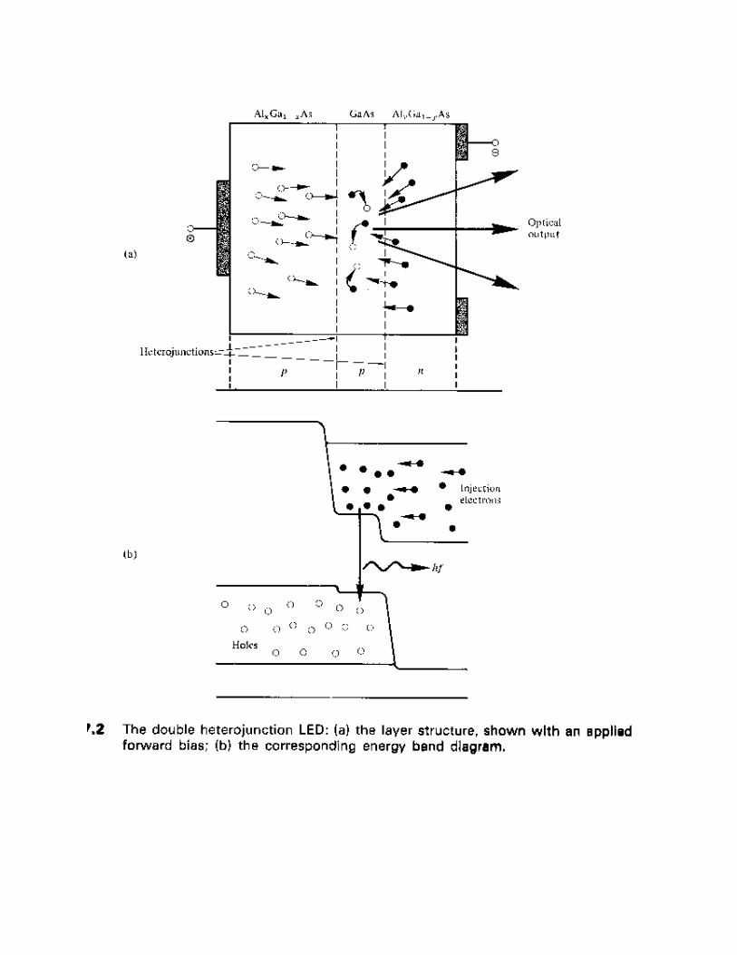


Edge Emitter LED This has a similar geometry to a
conventional contact stripe ILDIt takes advantage of transparent
guiding layers with very thin activelayer(50-100 μm)in order that the lightproduced in the active layer spreadsinto transparent layer, reducing selfabsorption in the active layer.

Edge Emitter LED
The Effective radiance at theemitting end face can be veryhigh giving an increasedcoupling efficiency into smallNA fiber compared withsurface emitter.

Edge Emitter LED
However Surface emittergenerally radiate more powerinto air (2.5-3 times) than ELEDSince the emitted light is lesseffected by re-absorption andinterfacial recombination.
Edge Emitter LED
But it has been seen thatELED couples more opticalpower into low NA (lessthan0.3) whereas SLEDjust does it’s opposite

Edge Emitter LED
The enhance wave guidingof the edge emitterenables it to couple 7.5times more power intolow NA than SLED
Edge Emitter LED
The Stripe geometryof ELED allows veryhigh carrier injectiondensities for a givendriving current.

Edge Emitter LED
Last but not the least ELEDhave better modulationBW (order of hundredsMHz) than comparablewith SLED


Coupling : ILD To Fiber

Related Documents