71 Mech. & Aerospace Eng. J. Vol. 2, No. 2, Nov. 2006 Sound Transmission through Laminated Composite Cylindrical Shells, Considering Transverse Shear Deformation K. Daneshjou 1 , A. Nouri 2 , and R. Talebitooti 3 Mech. Eng. Dep’t., Iran Univ. of Science and Tech. ABSTRACT Laminated composite shells are increasingly being used in various engineering applications, including aerospace, mechanical, marine, and automotive. In this paper, sound transmission through an infinite laminated composite cylindrical shell is studied in the context of the transmission of airborne sound into aircraft interior. The shell is immersed into an external fluid medium and contains internal fluid, while the airflow in external fluid medium is moving with a constant velocity. Modal impedance method, along with the first-order shear deformation theory (FSDT), is used to calculate the transmission loss (TL), considering three directions of the shell. The TL obtained in this study is compared with that of thin laminated composite obtained by others. The effects of structural properties and flight conditions on TL are studied for a range of values, especially, Mach number, aircraft flight altitude, shell thickness, and warp angle. Comparisons of the transmission loss are made among classical shell theory (CST) and FSDT for laminated composite and isotropic shells, which show close agreements. Key Words: Wave Transmission Loss, Laminated Composite Shell, First-order Shear Deformation, Plane !" #$% &’( ! ! " !#$ %& ’(& ) %&*+$ + % , + +- ./ 0+ * 1 % 2 . + 45 6 " !#$ 7- * 0 85 6*$ 7- * 0 85 +* 9& * : % (/ +; 4< + =& . * + >? 8 @: 7- + 8 * A+- +B C %+ ! *D $ . # E+ ! 8 FG H %+IJ 2 1 0FG A 6(/ ) + * 0 85 B: %* 8 BJ 2* 72 KJ . + C * 0 85 ( $ L! +A %& %* C * M * 45 6 " !# % 2 .5 655: @J . 6N=& ! O- 0D % %! @2 =& ! P1J+ Q ) " R ! +A GS + 0 85 ( * & (/ +; +* . + +IJ ! 7T 0 85 ( M %+IJ U$ % %* 8 BJ 2* 72 KJ JV %& !#$ W " * % & 2 .5 . &)* ’+ : " !#$ 85 ( ! 72 KJ % A+ % X :1 Y % 1- Associate Professor: [email protected] 2- PhD Student (Corresponding Author): ali_nor@ mail.iust.ac.ir 3- PhD Student: [email protected]

Welcome message from author
This document is posted to help you gain knowledge. Please leave a comment to let me know what you think about it! Share it to your friends and learn new things together.
Transcript
71 Mech. & Aerospace Eng. J. Vol. 2, No. 2, Nov. 2006
Sound Transmission through Laminated Composite Cylindrical Shells, Considering Transverse Shear Deformation
K. Daneshjou1, A. Nouri2, and R. Talebitooti3
Mech. Eng. Dep’t., Iran Univ. of Science and Tech.
ABSTRACT Laminated composite shells are increasingly being used in various engineering applications, including aerospace, mechanical, marine, and automotive. In this paper, sound transmission through an infinite laminated composite cylindrical shell is studied in the context of the transmission of airborne sound into aircraft interior. The shell is immersed into an external fluid medium and contains internal fluid, while the airflow in external fluid medium is moving with a constant velocity. Modal impedance method, along with the first-order shear deformation theory (FSDT), is used to calculate the transmission loss (TL), considering three directions of the shell. The TL obtained in this study is compared with that of thin laminated composite obtained by others. The effects of structural properties and flight conditions on TL are studied for a range of values, especially, Mach number, aircraft flight altitude, shell thickness, and warp angle. Comparisons of the transmission loss are made among classical shell theory (CST) and FSDT for laminated composite and isotropic shells, which show close agreements. Key Words: Wave Transmission Loss, Laminated Composite Shell, First-order Shear Deformation, Plane
اي با در نظراي كامپوزيت اليه هاي استوانه انتقال صوت در پوسته
گرفتن تغيير شكل برشي
���� ����� �� � � �� ��� ������ ����� ������� �� � ������� ����� ���� � ��� �������
چكيده��� !� �!���� ��" ��!�#��$ %�& ��'(��& ��)� �� � %�&��*+�$ +� %� ������� ,������+���+��- �����./ 0+�� �* � ���1�� %� �2�.+�
�4�5� 6�����" ��!�#��$ ��� �� 7-�� �* 0�� 8�5��� 6�*�$ 7-�� �* 0�� 8�5��� +�* 9�& �* ���:��� %� ��(�/ +��; ��4�<� �+�� �=� ��&�� .� ���* +� �>�? 8�� @�:� 7-�� +� ��� 8��* A+�- � +�B� �C %�+ !� �*�D ��� ���$ .#�� E�+ !��8���� �FG�� H����%+�IJ
�� ��2 ���1�� ��� 0�F�G� � A � 6�(�/ �)� +� �* 0�� 8�5��� �B�:� %��* 8�� �BJ�� 2�* 7�2 ���KJ .+� ���C ��* 0�� 8�5��� �(��$ L!�� +��A %�& ��� %��* ���C ��* M���� �* �4�5� 6����" ��!�#� %��� ��2 �.��5� 6�55:� ��� @�J .�6��N=&�!� O��- 0��D� %�
%!��� @���2 ����=� ��& !��� P�1J+� �Q�� ��� ��)� ��" �����R ����! � ��� �+��A ���GS �+�� 0�� 8�5��� �(� �* �&�� ��(�/ +��; +�* .+����� �+�IJ !� 7��T 0�� 8�5��� �(� M���� %+�IJ � ��� ��U$ %��� %��* 8�� �BJ�� 2�* 7�2 ���KJ ��J�V�� %�&��!�#��$ � W��" �* %� �&
��2 �.��5� ���.
�:هاي كليدي واژه�" ��!�#��$ ��� �8�5��� �(� ����! 7�2 ���KJ �%� �A+� %�X�:1� Y�� �%�
1- Associate Professor: [email protected]
2- PhD Student (Corresponding Author): ali_nor@ mail.iust.ac.ir
3- PhD Student: [email protected]
Mech. & Aerospace Eng. J. Vol. 2, No. 2, Nov. 2006 72
Introduction Composite panels and cylinders are extensively employed in the aerospace industry. Their applications are commonly found in aircrafts, helicopters, launch vehicles and engine cowlings. Ironically, the light weight advantage of the composite construction could lead to higher interior noise levels. The prediction of the sound transmission into such structures requires the analysis of acoustic wave propagation in composite cylindrical shell. With the increase awareness of, and sensitivity to, structural noise and vibration, research covering the vibration of composite shells has received considerable attention. Noise transmission, measured by transmission loss (TL) through the circular shell, has been studied by Smith [1], White [2], Koval [3-5], Blaise et al [6, 7] and Kim [8] for isotropic, orthotropic and laminated fiber-reinforced composite shells. Smith presented a theoretical study of transmission of sound energy through a thin, isotropic elastic cylindrical shell from an oblique plane wave excitation. White investigated sound transmission into finite cylindrical shells and found two important characteristics, the ring and coincidence frequencies, at which TL takes on minima. Koval extended Smith's work to present an analytical model for predicting of TL for isotropic, orthotropic, and laminated fiber-reinforced composite shells. The transmission loss prediction for orthotropic and multi-layered infinite cylinders was investigated in a series of papers by Blaise et al [6, 7]. They presented a displacement field which neglected the transverse shear and rotary inertia. The theoretical study of Koval (1980), for an infinite cylindrical shell, provided the first model for noise transmission loss of composite
constructions using classical laminated theory. Roussos et al. [9] gave a report prepared at the NASA Langley Research Centre about the theoretical and experimental study of noise transmission through composite plates. Tang et al. [10] considered an infinite cylindrical sandwich shell excited by an oblique plane sound wave with two independent incident angles. In most of studies surveyed above, numbers of terms used in the series solution were apparently insufficient to provide accurate results, which could have affected the very large TL’s estimated results. In addition, the deformation of the transverse plane due to transverse shear stress was neglected, whereas in thick shells and in high frequency, transverse shear deformation could become important. The objective of this paper is to study sound transmission through an infinite laminated composite cylindrical shell using “modal impedance method”. An aircraft fuselage in flight with an external airflow is modelled as an infinite cylindrical shell. The vibro-acoustic model of laminated composite shell is obtained in a series form using FSDT laminated shell vibration, without ignoring any of the three directions of the shell. The shell is assumed to be immersed in a fluid media and excited by an incident oblique plane sound wave. The properties of the internal and external fluids surrounding the shell may be different. To make sure an enough number of modes are included in the analysis, the convergence checking is preformed. Moreover, the effects of structural properties and flight conditions on TL are studied for a range of values, especially, Mach number, flight altitude of aircraft and angle of warp. Comparison of TL is made between isotropic and composite shell using FSDT and CST.
73 Mech. & Aerospace Eng. J. Vol. 2, No. 2, Nov. 2006
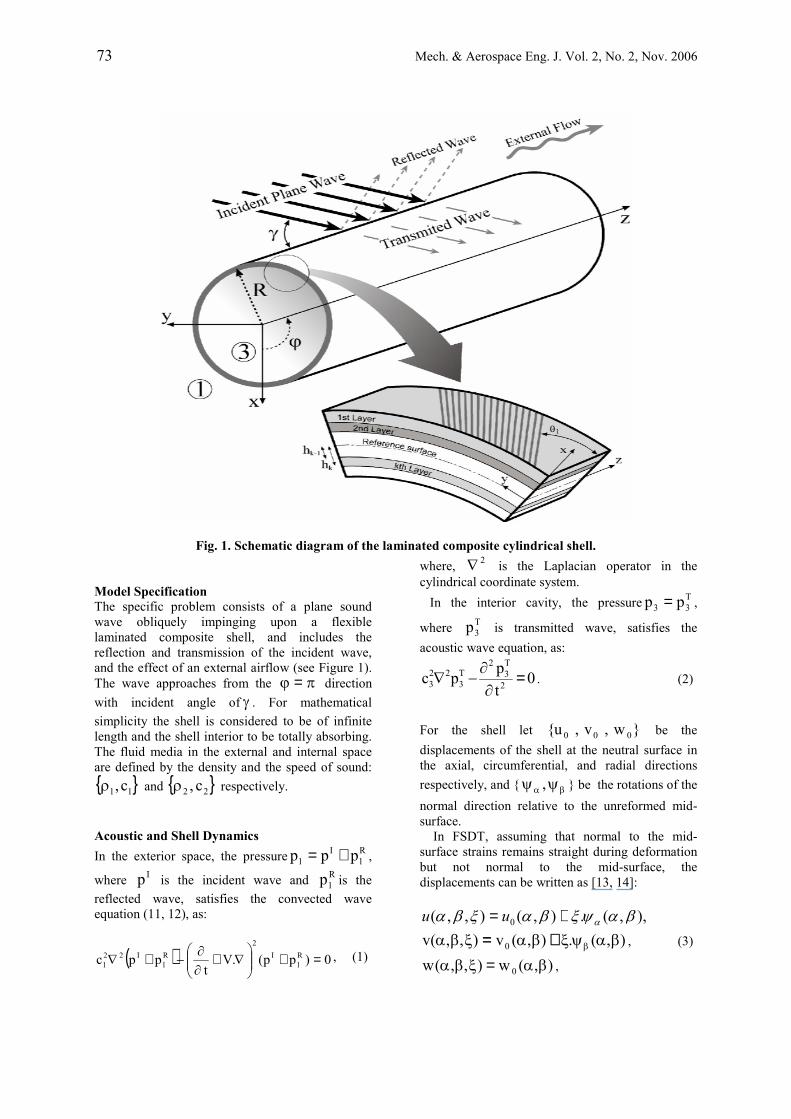
Fig. 1. Schematic diagram of the laminated composite cylindrical shell.
Model Specification The specific problem consists of a plane sound wave obliquely impinging upon a flexible laminated composite shell, and includes the reflection and transmission of the incident wave, and the effect of an external airflow (see Figure 1). The wave approaches from the π=ϕ direction with incident angle of γ . For mathematical simplicity the shell is considered to be of infinite length and the shell interior to be totally absorbing. The fluid media in the external and internal space are defined by the density and the speed of sound: { }11 c,ρ and { }22 c,ρ respectively.
Acoustic and Shell Dynamics In the exterior space, the pressure R
1I
1 ppp += ,
where Ip is the incident wave and R1p is the
reflected wave, satisfies the convected wave equation (11, 12), as:
( ) 0)pp(.Vt
ppc Rl
I2
Rl
I221 =+
∇+
∂∂
−+∇ , (1)
where, 2∇ is the Laplacian operator in the cylindrical coordinate system. In the interior cavity, the pressure T
33 pp = ,
where T3p is transmitted wave, satisfies the
acoustic wave equation, as:
0tppc 2
T3
2T3
223 =
∂∂
−∇ . (2)
For the shell let }w,v,u{ 000 be the displacements of the shell at the neutral surface in the axial, circumferential, and radial directions respectively, and { βα ψψ , } be the rotations of the normal direction relative to the unreformed mid-surface. In FSDT, assuming that normal to the mid-surface strains remains straight during deformation but not normal to the mid-surface, the displacements can be written as [13, 14]:
),,(.),(),,( 0 βαψξβαξβα α+= uu),(.),(v),,(v 0 βαψξβαξβα β+= , (3)
),(w),,(w 0 βα=ξβα ,
Mech. & Aerospace Eng. J. Vol. 2, No. 2, Nov. 2006 74
where, α and β are curvilinear surface coordinates and ξ is the distance from mid-surface. The middle surface strains and curvature change for a thick cylindrical shell are defined as:
α∂∂=ε α
00
u,
Rwv 00
0 +β∂
∂=ε β ,
α∂∂=ε αβ
00
v,
β∂∂=ε βα
00
u,
ααξ ψ+α∂
∂=γ 00
w,
ββξ ψ+−β∂
∂=γRvw 00
0 , (4)
α∂ψ∂= α
αk ,β∂ψ∂
= ββk ,
α∂ψ∂
= βαβk ,
β∂ψ∂= α
βαk .
In above equation αε0 , βε0 , αβε0 , βαε0 are
normal and shear mid-surface strains; αξγ0 , βξγ0
are shear strains in the z direction; αk , βk , αβk ,
βαk are the curvature and twist changes. The subscript (0) refers to the middle surface in above equations. The forces and moments resultant, obtained by integrating the stresses over the shell thickness, are:
κκκκεεεε
=
βα
αβ
β
α
βα
αβ
β
α
βα
αβ
β
α
βα
αβ
β
α
0
0
0
0
6666261666662616
6666261666662616
2626221226262212
1616121116161211
6666261666662616
6666261666662616
2612121226262212
1616121116161211
DDDDBBBBDDDDBBBBDDDDBBBBDDDDBBBBBBBBAAAABBBBAAAABBBBAAAABBBBAAAA
MMMMNNNN
(5)
γγ
=
βξ
αξ
β
α
0
0
4445
4555
AAAA
, (6)
where, N is membrane force resultant; M is moment resultant; αQ , βQ represent transverse
shearing force resultants; ijA , ijB and ijD are extensional, coupling and bending stiffness. For a composite shell composed of different orthotropic materials the stiffness can be written as [13]:
6,2,1j,i
)hh(Q31D
)hh(Q21B
)hh(QA
L
L
L
N
1k
31k
3k
kijij
N
1k
21k
2k
kijij
N
1k1kk
kijij
=
−=
−=
−=
∑
∑
∑
=−
=−
=−
, (7)
5,4j,i
)hh(QKK31D
)hh(QKK21B
)hh(QKKA
L
L
L
N
1k
31k
3k
kijjiij
N
1k
21k
2k
kijjiij
N
1k1kk
kijjiij
=
−=
−=
−=
∑
∑
∑
=−
=−
=−
, (8)
where, 1kh − and kh denote the distances from the reference surface to the outer and inner surfaces of the kth layer as shown in Fig. 1, LN is the number
of layers in the laminated shell and 65K = is shear correction coefficient [13- 15]. In both of equations (7, 8) the constants ijQ are transformed stiffness coefficients, which are found from the following equation:
[ ] [ ] [ ][ ]TQTQ 1−= , (9) where, [T] is the transformation matrix for principal material coordinate and shell coordinates system and defined as:
θθθθθθθθθθθθθθ
=
k2
k2
kkkk
kkk2
k2
kkk2
k2
sin-cossincossincos-sin2cos-cossin
sin2cossincos]T[
(10) In addition kθ is orientation of fibres and ijQ are material constants that were defined in terms of material properties of the orthotropic ply, as:
∆= 1EQ 111 ,
∆= 1EQ 222 , (11)
1266 GQ = ,∆ν=
∆ν= 12
221
112 EEQ ,
21121 νν−=∆ ,
where, 1E and 2E are modulus of elasticity in the
1 and 2 directions, respectively; 12G is modulus of
75 Mech. & Aerospace Eng. J. Vol. 2, No. 2, Nov. 2006
shear stiffness and )ji,2,1j,i(ij ≠=ν are Poisson’s ratios. Note that we described the fiber coordinates of orthotropic, as 1 and 2, where direction 1 is parallel to the fibers and 2 is perpendicular to them. Considering first-order shear deformation theory, the equations of motion of the laminated composite cylindrical shell are defined as [13, 14]:
)IuI(qNN 2
2201 αα
αβα ψ+=+β∂
∂+
α∂∂
&&&& , (12)
)IvI(qR
QNN 22
201 ββ
βαββ ψ+=++α∂
∂+
β∂
∂&&&& (13)
)( 201wIq
QQR
N&&=+
∂∂
+∂∂+− ξ
βαβ
βα, (14)
)IuI(mQNM 2
3202 ααα
βαα ψ+=+−β∂
∂+
α∂∂
&&&& , (15)
)IvI(mQNM 2
3202 βββ
αββ ψ+=+−α∂
∂+
β∂
∂&&&& . (16)
Equation. (12-14) present the equation of the translation motion and Equation. (15, 16) present the equations of rotational motion. In above equations αq , βq and ξq are external forces (per
unit area) in the βα, and ξ directions,
respectively, αm and βm represent distributed couples about the middle surface of the shell (per unit length) and two dots represent the second derivative of these terms with respect to time, and:
3,2,1iR
III 1i
ii =
+= + , (17)
4,3,2,1idILN
1k
1i2h
2hki =ξξρ=∑ ∫
=
−
−
, (18)
where, kρ is the mass density of k-th layer. For cylindrical shells in Fig. 1, ϕ=β R and z=α ,therefore the equations of motion can be written in terms of displacements [13, 15], as:
{ } { } { }qu]M[u]L[ =+ && , (19) where,
{ } [ ]Tz00o ,,w,v,uu ϕψψ= , (20)
=
32
32
1
21
21
I00I00I00I00I00I00I00I00I
]M[ , (21)
and
{ } ( )[ ]TT3
R1
I1 0,0,ppp,0,0q −+= . (22)
The ijL coefficients are shown in appendix A. In addition, the classical equations of thin laminated composite shell can be found in appendix B [15, 16]. Boundary Conditions We have to consider, for a coupled fluid-structure problem, the boundary conditions at internal and external shell surfaces. On the internal and external shell surfaces, the particle velocities of the acoustic media in the normal direction have to be equal to the normal velocity of the shell. These results are shown in the following equations [11, 17]:
w.Vtr
)pp(2
1Rr
R1
I
∇+
∂∂
ρ−=∂+∂
=
, (23)
2
2
3Rr
T3
tw
rp
∂∂
ρ−=∂∂
=
, (24)
which describe the effect of the fluid pressure on the shell motion. Solution of the Vibro-acoustic Equations The harmonic plane wave Ip in cylindrical geometry, incident from outside to the direction shown in Fig. 1, can be expressed as [6, 8, 18]:
,)()(),,,(0
)]([10
1∑∞
=
−−−=m
mzktjrm
mm
I zerkJjPtzrp ϕωεθ
(25) where, mε is the Neumann factor given by:
≥=
=,12,01
mm
mε (26)
and
.sin,cos 1111 γγ kkkk rz == (27)
Mech. & Aerospace Eng. J. Vol. 2, No. 2, Nov. 2006 76
In addition 1k is the wave number in the moving
medium and mJ is the Bessel function of the first
kind of order m, 0p is the amplitude of the incident
wave, 1j −= , m=0,1,2,3, . . . and ω is the angular frequency. The wave number in moving medium can be written as [3]:
γ+
ω=cosM1
1c
k11
1 , (28)
where, )cV(M 11 = is the Mach number of the external flow. Because the travelling waves in the acoustic media and inside the shell are driven by the incident-travelling wave, the wave numbers (or trace velocities) in the z direction should match throughout the system, therefore z1z3 kk = and:
2z3
23r3z1z3
33 kkk,kk,
ck −==ω= .(29)
The waves radiated from the shell to the outside and into the cavity, R
1p and T3p , can be represented
as:
∑∞
=
ϕ−−ω=θ0m
)]mzkt(j[r1
2m
Rm1
R1
z1e)rk(HP)t,,z,r(p ,
(30)
∑∞
=
ϕ−−ω=θ0m
)]mzkt(j[r3
1m
Tm3
T3
z1e)rk(HP)t,,z,r(p ,
(31) where, 1
mH and 2mH are the Hankel functions of
the first and second kind of order m, respectively. The former represents the incoming wave and the latter the outgoing wave. The displacement and rotation terms of mid surface can be written as follows:
)]mzkt(j[
0m
m
zm
m
m
m
0
z0
0
0
0
z1e
jjWVjUj
wvu
ϕ−−ω∞
=
ϕθ
∑
ψψ
=
ψψ
. (32)
Here, in Equation. (32), { }mmm W,V,U and
{ }mzm , ϕψψ are unknown complex amplitudes of the displacement and rotation components, respectively. It can be seen that for each mode number m, there are seven unknowns { }T
m3Rm1mzmmmm P,P,,,W,V,U ϕψψ and seven
equations (five equation of motion and two boundary condition). To obtain simplified and meaningful results, one can get a set of equations in terms of R
m1P , Tm3P and mW by
eliminating mm V,U , mzm , ϕψψ . Solving these coupled equations yields:
Shm
Rm
Tm
Shm
Im
Tm
r12
r1mmm0
Rm1 ZZZ
)ZZZ(
)Rk(H
)Rk(J)j(PP++++
′′
−ε−= , (33)
,))((
)()()(
31
31
211112
03Shm
Tm
Rmrr
Im
Rmrmrm
mTm
ZZZRkHk
ckZZRkJkjPP
++′+′−
−−=ρ
ωρε (34)
,)(
)()()( 2
1
21111
0 Shm
Tm
Rm
Im
Rmrmrm
mm ZZZckZZRkJk
jPW++
+−−=
ωρω
ε (35)
where ,
)Rk(J)Rk(J
kiZ
r1m
r1m
r1
1Im ′
ρω= , (36)
211
r12
r12
r1
1Rm
ck
)Rk(H
)Rk(Hk
iZ
ω′
ρω−= , (37)
)Rk(H
)Rk(Hk
iZr3
1
r31
r2
2Tm ′
ρω= , (38)
.1
)()()()( 31
312
10
m
m
rTmr
Rmrm
mmSh
m
Dj
WjRkHPRkHPRkJjP
Z
ω
ωε
=
−+−=
(39) Here, in Equation. (33) to (39), the primes denote derivatives with respect to the argument; ,ZI
mRmZ ,
TmZ are modal characteristic acoustic impedances
of the fluids; shmZ is the modal impedance of the
shell; and mD is the modal amplitude of the displacement component of the shell in the radial direction with a unit pressure.

77 Mech. & Aerospace Eng. J. Vol. 2, No. 2, Nov. 2006
Transmission Loss It is convenient to represent the solution in TL for the design purpose. TL can be defined as the ratio of the incoming and transmitted sound powers per unit length of the cylinder [6, 8], as:
T
I
10 WWlog10TL = , (40)
where, IW is the incident power and TW is the transmitted power per unit length of the shell [8], as:
RcPcosW11
20I ×
ργ= , (41)
Rr,dr)w(t.pRe21W
2
00
T3
T =
ϕ∂∂= ∫
π∗ , (42)
where, Re {.} and the superscript ∗ represent the real part and the complex conjugate of the argument, respectively. Substituting Equation (31, 32) by using Equation. (33, 35) into Equation (40) leads to the expression of TL in terms of the modal impedances, as:
∑∞
= ++
+
ωε−=
0m2Sh
mTm
Rm
Tm
Rm
*
11r1
m10
ZZZ
]ZRe[]ZRe[ckRk
2log10TL , (43)
where, |.| is the absolute value of the argument. In addition, the average power transmission coefficient τ is given as [19]:
∫γ
γγγγγτ=τ max
mindcossin)( , (44)
where, )(γτ is the power transmission coefficient
calculated for the incident angle γ ; minγ and
maxγ are the critical angles of incidence upon the shell [3]. Incidence wave out of this range, to be totally scattered with no transmission into the shell interior. The integration in Eq. (44) is conducted numerically by the Simpson’s rule using an integration step-size of °2 [20]. The average
avTL shown in Fig. 2. is given as [21]:
τ
= 1log10TL 10av . (45)
101
102
103
104
10
20
30
40
50
60
70
80
Frequency (Hz)
TL(d
B)
Fig. 2. TL averaged for random incident angles.
Convergence checking As one can see in Equation. (25) and (30–32), the solutions, are obtained in series form. Therefore, one has to ensure that enough number of modes are included in the analysis to make the solution converge. When insufficient number of modes is used in the calculation, the resulting TL becomes overestimated. Once the solution converges at a given frequency, it can be assumed to converge in all frequencies lower than that, because more terms are necessary to be used in the calculation for a higher frequency. Therefore, we construct an iterative procedure in each frequency, considering the maximum iteration number. Unless the convergence condition is met, it iterates again. When the TL’s calculated at two successive calculations are within a pre-set error bound, the solution is considered to have converged. Fig. 3 shows the concept of this convergence. Changes in the calculated TL as the number of modes increases are shown in Fig. 4 for the case of a composite shell specified in table 1 driven at 1000 Hz. Fig. 5 shows the convergence trend for the same case but at 10,000 Hz, which indicates that with increasing the frequency, the number of modes for convergence is increased.

Mech. & Aerospace Eng. J. Vol. 2, No. 2, Nov. 2006 78
Fig. 3. Algorithm for identifying the optimum mode number.
0 5 10 15 20 25 30 35 4015
20
25
30
35
40
Mode Number
TL(d
B)
Fig. 4. Mode convergence diagram for 10-layers laminated composite at 1000 Hz.
0 50 100 150 200 250 3000
10
20
30
40
50
60
Mode Number
TL(d
B)
Fig. 5. Mode convergence diagram for the 10- layers composite shell at 10000 Hz.
Table1. Geometrical and environmental properties.
Shell Cavity
Ambient
Material (Fluid) Al G/E Air Air
Density )mkg( 3 2760 1600 1.21 1.21
1E (GPa) 71 138 - -
2E (GPa) 71 8.9 - -
12G (GPa) 27.7 7.1
13G (GPa) 27.7 7.1
23G (GPa) 27.7 6.2
θνz 0.3 0.26 - - Sound Speed
)sm(5316 5622 343 343
Incidence Angle 45
Numerical result Numerical results have been generated for geometry typical of a narrow-bodied jet fuselage made of the laminated composite shell with radius R=1.83 m and total thickness h=1.59 mm. Both internal and external fluids are considered at sea level conditions, and its external flow Mach number is assumed as 0M1 = for the purpose of this study, except where noted. In addition each layer of the composite shell is made of Graphite/Epoxy (table 1). The plies are arranged in a S]0,45,45,90,0[ ooooo − pattern. Comparison of the transmission loss is made among classical shell theory (CST) and FSDT for composite and isotropic shells. The basic shell dimensions and simulation conditions used in the study are listed in Table 1. Parametric numerical studies of transmission loss (TL) are conducted for broadband frequency. These studies provide insight into the effect of the acoustic properties of the fluids and the structural or material parameters of the shells on TL. The theoretical model developed can be used very effectively in the basic design stage of cylinder-shape vibro-acoustic systems and show the effect of the acoustic properties of the fluids and the structural parameters on TL.
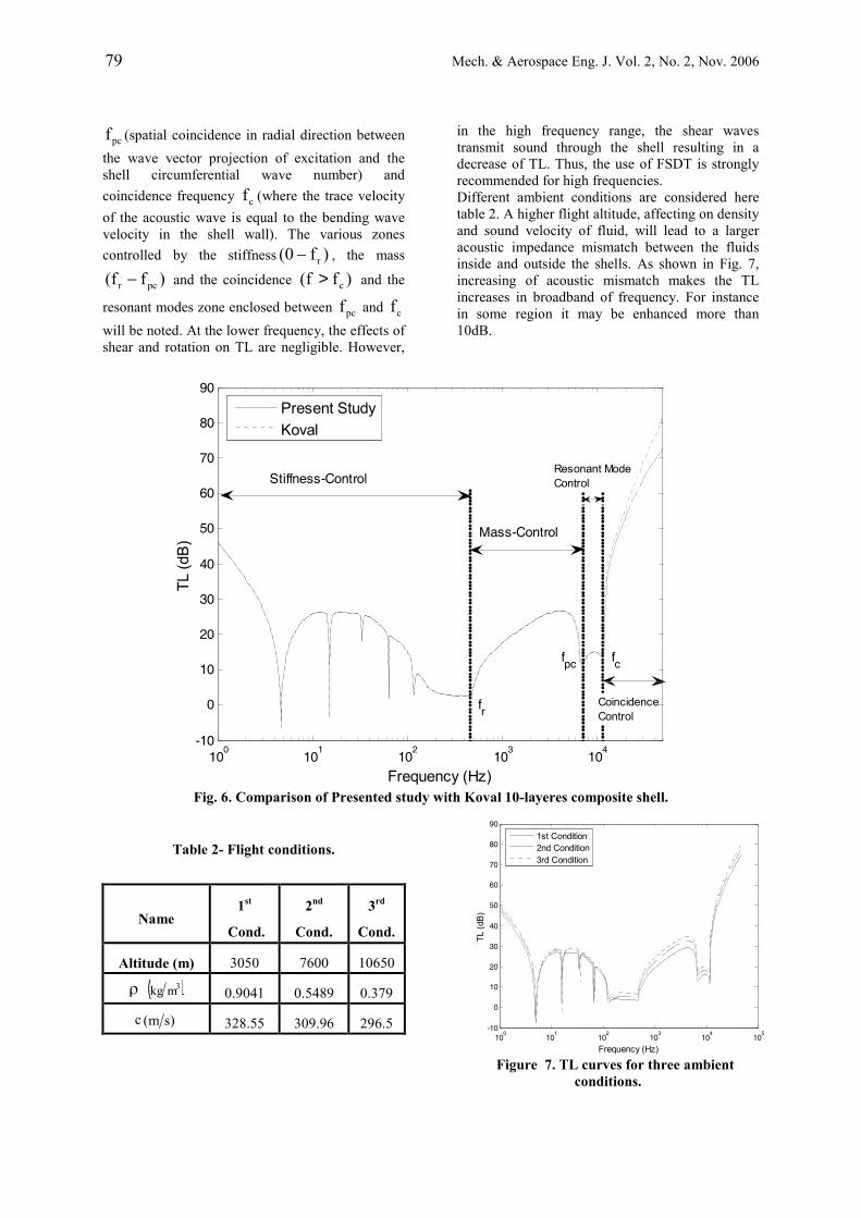
Fig. 6 shows a comparison on TL for the thin shell theory purposed by Koval [5] and the first-order shell theory presented in this study. As shown, three important frequencies are recognized: ring frequency rf (where the wavelength of a longitudinal wave in the shell equal to the circumference), critical pseudo-coincidence
Calculation of TL at each Frequency
701TL(n))-1)(TL(n ABS −<+
Find Optimum Mode Number
Mode Number n=n+1
No
Yes
79 Mech. & Aerospace Eng. J. Vol. 2, No. 2, Nov. 2006
pcf (spatial coincidence in radial direction between the wave vector projection of excitation and the shell circumferential wave number) and coincidence frequency cf (where the trace velocity of the acoustic wave is equal to the bending wave velocity in the shell wall). The various zones controlled by the stiffness )f0( r− , the mass
)ff( pcr − and the coincidence )ff( c> and the
resonant modes zone enclosed between pcf and cfwill be noted. At the lower frequency, the effects of shear and rotation on TL are negligible. However,
in the high frequency range, the shear waves transmit sound through the shell resulting in a decrease of TL. Thus, the use of FSDT is strongly recommended for high frequencies. Different ambient conditions are considered here table 2. A higher flight altitude, affecting on density and sound velocity of fluid, will lead to a larger acoustic impedance mismatch between the fluids inside and outside the shells. As shown in Fig. 7, increasing of acoustic mismatch makes the TL increases in broadband of frequency. For instance in some region it may be enhanced more than 10dB.
100
101
102
103
104
-10
0
10
20
30
40
50
60
70
80
90
Frequency (Hz)
TL(d
B)
Present StudyKoval
Stiffness-Control
Mass-Control
Resonant ModeControl
CoincidenceControl
fr
fpc fc
Fig. 6. Comparison of Presented study with Koval 10-layeres composite shell.
Table 2- Flight conditions.
3rd
Cond.
2nd
Cond.
1st
Cond. Name
10650 7600 3050 Altitude (m)
0.379 0.5489 0.9041 ρ ( )3mkg
296.5 309.96 328.55 c )sm(10
010
110
210
310
410
5-10
0
10
20
30
40
50
60
70
80
90
Frequency (Hz)
TL(d
B)
1st Condition2nd Condition3rd Condition
Figure 7. TL curves for three ambient conditions.

Mech. & Aerospace Eng. J. Vol. 2, No. 2, Nov. 2006 80
External airflow influences the axial and radial wave numbers; thus, the TL will be changed due to this effect. Fig. 8, shows the effects of Mach numbers with M = 0, 0.5, and 1.0, on TL. With increasing Mach number, the TL is descending in stiffness-controlled region (below the ring frequency), whereas in upper frequency more than ring frequency it is ascending. Also, the coincidence frequency is shifted upwards with increase of Mach number.
100
101
102
103
104
-10
0
10
20
30
40
50
60
70
80
Frequency (Hz)
TL(d
B)
M=0.0M=0.5M=1.0
Fig. 8. TL curves for 10-layered laminated shell subjected in uniform flow.
100
101
102
103
104
-10
0
10
20
30
40
50
60
70
80
90
Frequency (Hz)
TL(d
B)
Graphite/EpoxyAluminum
Fig. 9. Comparison between Aluminium and 10- layers laminate composite shell.
Fig. 9 shows a comparison between the cylinder transmission loss for an aluminium shell and a 10-layered composite shell of same weight. The figure indicate that the ring frequency is shifted upwards, so that there appear to be a gain in TL below the ring frequency, but composite shell does not appear to be effective as an aluminium shell above the ring frequency. This appear to be due to the fact that the critical frequency of a composite shell is lower than it is for an aluminium shell, so that the TL curve is never able to reach a full mass law behaviour because the ring frequency and the critical frequency are closer together. It thus appears that a composite shell does not appear to offer significant advantages over an aluminium shell, as regards noise attenuation.
Fig. 10, shows the effect on TL of the angle of warp, kθ of the individual layers of the composite shell. In this Figure, all of the layers have the same angle kθ . The individual curves in Fig.10
Correspond to o0k =θ , o30 , o45 , o60 , o90 . The incidence angle of the incident plane wave is o30=θ . The results shown in the curve indicate that the noise attenuation of a composite shell is sensitive to the angle of warp and suggests the possibility of tailoring a composite shell a specific need.
100
101
102
103
104
-10
0
10
20
30
40
50
60
70
80
Frequency (Hz)
TL(d
B)
θ =0θ =20θ =45θ =60θ =90
Fig. 10. Effect of fibre orientation on TL, at o30=γ for a 10-layered composite shell.
Fig. 11 shows the effect of the composite material on TL. Materials chosen for the comparison are Graphite/Epoxy, Glass/ Epoxy and Boron/Epoxy as shown in table (3). The figure shows that material must be chosen properly to enhance TL at stiffness-controlled zone. The best result is obtained from Boron/Epoxy shell, which represents a desirable level of TL at stiffness-control zone. It is readily seen that, in higher frequency, because of density of materials, the TL curves are ascending. Therefore the TL of Glass/Epoxy is higher than the other materials in mass-controlled region.
100
101
102
103
104
-10
0
10
20
30
40
50
60
70
80
Frequency (Hz)
TL(d
B)
GraphiteGlassBoron
Fig. 11. TL curves for 10-layers laminated composite shell with different material.
81 Mech. & Aerospace Eng. J. Vol. 2, No. 2, Nov. 2006
Table3. Composite materials properties.
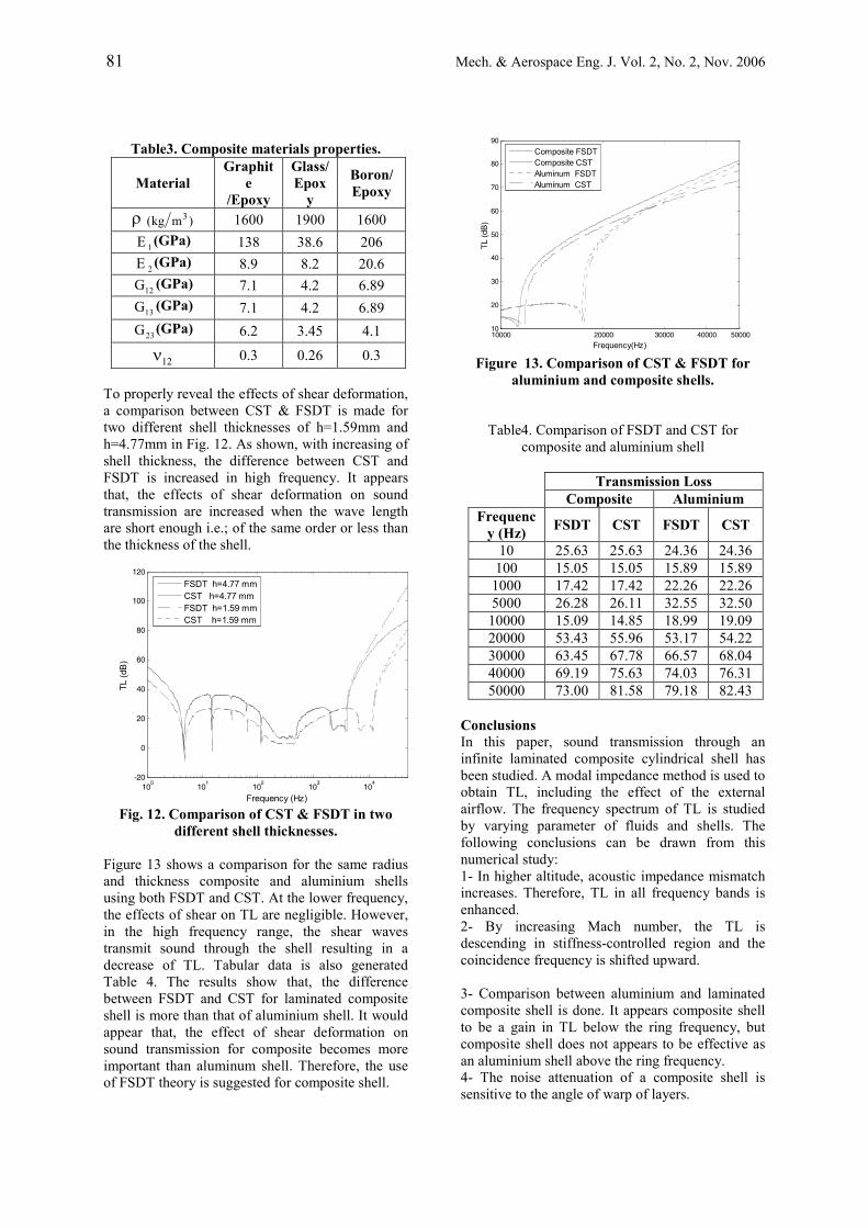
To properly reveal the effects of shear deformation, a comparison between CST & FSDT is made for two different shell thicknesses of h=1.59mm and h=4.77mm in Fig. 12. As shown, with increasing of shell thickness, the difference between CST and FSDT is increased in high frequency. It appears that, the effects of shear deformation on sound transmission are increased when the wave length are short enough i.e.; of the same order or less than the thickness of the shell.
100
101
102
103
104
-20
0
20
40
60
80
100
120
Frequency (Hz)
TL(d
B)
FSDT h=4.77 mmCST h=4.77 mmFSDT h=1.59 mmCST h=1.59 mm
Fig. 12. Comparison of CST & FSDT in two different shell thicknesses.
Figure 13 shows a comparison for the same radius and thickness composite and aluminium shells using both FSDT and CST. At the lower frequency, the effects of shear on TL are negligible. However, in the high frequency range, the shear waves transmit sound through the shell resulting in a decrease of TL. Tabular data is also generated Table 4. The results show that, the difference between FSDT and CST for laminated composite shell is more than that of aluminium shell. It would appear that, the effect of shear deformation on sound transmission for composite becomes more important than aluminum shell. Therefore, the use of FSDT theory is suggested for composite shell.
10000 20000 30000 40000 5000010
20
30
40
50
60
70
80
90
Frequency(Hz)
TL(d
B)
Composite FSDTComposite CSTAluminum FSDTAluminum CST
Figure 13. Comparison of CST & FSDT for aluminium and composite shells.
Table4. Comparison of FSDT and CST for composite and aluminium shell
Conclusions In this paper, sound transmission through an infinite laminated composite cylindrical shell has been studied. A modal impedance method is used to obtain TL, including the effect of the external airflow. The frequency spectrum of TL is studied by varying parameter of fluids and shells. The following conclusions can be drawn from this numerical study: 1- In higher altitude, acoustic impedance mismatch increases. Therefore, TL in all frequency bands is enhanced. 2- By increasing Mach number, the TL is descending in stiffness-controlled region and the coincidence frequency is shifted upward. 3- Comparison between aluminium and laminated composite shell is done. It appears composite shell to be a gain in TL below the ring frequency, but composite shell does not appears to be effective as an aluminium shell above the ring frequency. 4- The noise attenuation of a composite shell is sensitive to the angle of warp of layers.
Material Graphit
e/Epoxy
Glass/ Epox
y
Boron/ Epoxy
ρ )mkg( 3 1600 1900 1600
1E (GPa) 138 38.6 206
2E (GPa) 8.9 8.2 20.6
12G (GPa) 7.1 4.2 6.89
13G (GPa) 7.1 4.2 6.89
23G (GPa) 6.2 3.45 4.1
12ν 0.3 0.26 0.3
Transmission Loss Composite Aluminium
Frequency (Hz) FSDT CST FSDT CST
10 25.63 25.63 24.36 24.36 100 15.05 15.05 15.89 15.89
1000 17.42 17.42 22.26 22.26 5000 26.28 26.11 32.55 32.50 10000 15.09 14.85 18.99 19.09 20000 53.43 55.96 53.17 54.22 30000 63.45 67.78 66.57 68.04 40000 69.19 75.63 74.03 76.31 50000 73.00 81.58 79.18 82.43

Mech. & Aerospace Eng. J. Vol. 2, No. 2, Nov. 2006 82
5- Since, the effect of shear waves on sound transmission for composite becomes more important than aluminum shell, the use of FSDT theory is strongly recommended for composite shell. Appendix A The ijL coefficients are given below
2
2
12
2
266
216
2
2
1111 tI
RA
zRA2
zAL
∂∂
−ϕ∂∂+
ϕ∂∂∂+
∂∂=
2
2
226
26612
2
2
1612 RA
zRAA
zAL
ϕ∂∂+
ϕ∂∂∂++
∂∂= ,
ϕ∂∂
+
∂∂= 2
261213 R
AzR
AL ,
2
2
22
2
266
216
2
2
1114 tI
RB
zRB2
zBL
∂∂
−ϕ∂∂+
ϕ∂∂∂+
∂∂= ,
2
2
226
26612
2
2
1615 RB
zRBB
zBL
ϕ∂∂+
ϕ∂∂∂++
∂∂= ,
2
2
1
244
2
2
222
226
2
2
6622
tI
RA
RA
zRA2
zAL
∂∂
−
−ϕ∂∂+
ϕ∂∂∂+
∂∂=
ϕ∂∂++
∂∂+= 2
4422452623 R
AAzR
AAL ,
RA
RB
zRBB
zBL 45
2
2
226
26612
2
2
1624 +ϕ∂∂+
ϕ∂∂∂++
∂∂= ,
2
2
2244
2
2
222
226
2
2
6625 tI
RA
RB
zRB2
zBL
∂∂
−+ϕ∂∂+
ϕ∂∂∂+
∂∂=
2
2
1222
2
2
244
245
2
2
5533 tI
RA
RA
zRA2
zAL
∂∂
−+ϕ∂∂
−ϕ∂∂
∂−
∂∂
−=
ϕ∂∂
−+
∂∂
+−=
RA
RB
zRBAL 45
22612
5534,
ϕ∂∂
−+
∂∂
+−=
RA
RB
zRBAL 44
22226
4535,
2
2
32
2
26616
2
2
115544 tI
RD
zRD2
zDAL
∂∂
−ϕ∂∂+
ϕ∂∂∂+
∂∂+−=
2
2
2266612
2
2
164545 RD
zRDD
zDAL
ϕ∂∂+
ϕ∂∂∂++
∂∂+−= ,
2
2
32
2
222
226
2
2
664455 tI
RD
zRD2
zDAL
∂∂
−ϕ∂∂+
ϕ∂∂∂+
∂∂+−= ,
jiij LL = , (A-1)
6,5,4,2,1,
ˆ
ˆ
ˆ
=
−=+=
−=+=
−=+=
ji
RE
DDR
EDD
RD
BBR
DBB
RB
AARB
AA
ijijij
ijijij
ijijij
ijijij
ijijij
ijijij
(A-2) Appendix B Governing equations of thin laminated composite shells According to Kirchhoff hypothesis of neglecting shear deformation and the assumption that the zε is negligible, for laminated composite shell the mid-surface strain and curvature changes as follows:
α∂∂=ε αu
0 ,
Rwv
0 +β∂∂=ε β ,
β∂∂+
α∂∂=γ αβ
uv0 ,
2
2wkα∂∂
−=α ,
2
2wRvk
β∂∂
−
β∂∂=β ,
α∂β∂∂
−
α∂∂=τ w2
Rv 2
, (B-1)
where, }w,,u{ ν are the displacements of the shell at the neutral surface in the axial, circumferential and radial directions respectively. The forces N and moments M resultant, obtained by integrating the stresses over the shell thickness, are:
τ
γεε
=
β
α
αβ
β
α
αβ
β
α
αβ
β
α
kk
DDDBBBDDDBBBDDDBBBBBBAAABBBAAABBBAAA
MMMNNN
0
0
0
662616662616
262212262212
161211161211
662616662616
262212262212
161211161211
.
(B-2) Equations of motion of a laminated composite thin cylindrical shell in cylindrical coordinate as follows:
2
2
zzz
tuIq
zN
R1
zN
∂∂
−=+θ∂∂
∂+∂∂ θ , (B-3)
83 Mech. & Aerospace Eng. J. Vol. 2, No. 2, Nov. 2006
2
2zz
tvIq
zMM
R1
R1
zNN
R1
∂∂
−=+
∂∂+
θ∂∂+
∂∂+
θ∂∂
θθθθθ ,
(B-4)
.
112
2
2
2
2
2
twI
qz
MMRRz
MRz
NR
N zzz
∂∂
−=
+
∂∂
+∂∂
+∂∂
∂+
∂∂
+− ξθθθθ
θθ
(B-5) The equation of motion can be written in terms of displacements as:
quMuL iijiij =+ && , (B-6) Where,
[ ] Ti w,v,uu = , (B-7)
≠=
=jj0jiI
Mij , (B-8)
( )[ ]TT
3R1
I1 ppp,0,0q −+= . (B-9)
The ijL coefficients are given as:
2
2
266
216
2
2
1111 RA
zRA2
zAL
ϕ∂∂+
ϕ∂∂∂+
∂∂= ,
2
2
226
212
2
2
1612 RA
zRA
zAL
ϕ∂∂+
ϕ∂∂∂+
∂∂= ,
3
3
326
2
3
217
2
316
3
3
11
*26*
1213
3ϕϕϕ
ϕ
∂∂
−∂∂∂
−∂∂
∂−
∂∂
−∂∂+
∂∂=
RB
zRB
zRB
zB
RA
zAL
,
2
2
222
226
2
2
6622 RA
zRA2
zAL
ϕ∂∂′
+ϕ∂∂
∂′+
∂∂′= ,
,3 3
3
322
2
3
226
2
317
3
3
16
*22*
2623
ϕϕϕ
ϕ
∂∂
−∂∂∂
−∂∂
∂−
∂∂
−∂∂+
∂∂=
RB
zRB
zRB
zB
RA
zAL
4
4
417
3
4
326
22
4
217
3
416
4
4
112
2
2
*22
2*26
2
2*12
*22
33
42
42
42
ϕϕϕ
ϕϕ
ϕ
∂∂
∂∂∂+
∂∂∂+
∂∂∂+
∂∂+
∂∂
−
∂∂∂
−∂∂
−=
RD
zRD
zRD
zRD
zD
RB
zRB
zB
RAL
jiij LL = , (B-10)
RDA
RBAA 66
6612
1212 +++= ,
)66,26,22,16ij(RB
AA ijijij =+= ,
661217 B2BB += ,
661217 D2DD += ,
),66,26,22,17,16( =+= ijRD
BB ijijij
)66,26,22( =+=′ ijRB
AA ijijij ,
)RB
,RA
()B,A( ijij*ij
*ij = ,
)RB
,RA
()B,A( ijij*ij
*ij = . (B-11)
References 1. Smith, P.W. “Sound Transmission Through Thin Cylindrical Shells”, J. Acoustical Society of America, Vol. 29, No.6, pp. 721-729, 1957. 2. White, P. “Sound Transmission through a Finite, Closed, Cylindrical Shell”, J. Acoustical Society of America, Vol. 40, No. 5 pp. 1124- 1130, 1966. 3. Koval, L.R. “On Sound Transmission into a Thin Cylindrical Shell under Flight Conditions”, J. Sound and Vibration, Vol. 48, No.2, pp. 265-275, 1976. 4. Koval, L.R. “On Sound Transmission into an Orthotropic Shell”, J. Sound and Vibration Vol. 63, No.1, pp. 51-59, 1979. 5. Koval, L.R. “Sound Transmission into a Laminated Composite Cylindrical Shell”, J. Sound and Vibration, Vol. 71, No. 4, pp. 523-530, 1980. 6. Blaise, A., Lesueur C., Gotteland M., Barbe M. “On Sound Transmission into an Orthotropic Infinite Shell: Comparison with Koval Result and Understanding of Phenomena”, J. Sound and Vibration, Vol. 150, No.2, pp.233-243, 1991. 7. Blaise, A. and Lesueur, C., “Acoustic Transmission Through a 2-D Orthotropic Multi-layered Infinite Cylindrical Shell”, J. Sound and Vibration, Vol. 155, No. 1, pp. 95-109, 1992. 8. Lee, J.H. and Kim, J. “Study on Sound Transmission Characteristics of a Cylindrical Shell Using Analytical and Experimental Models”, Applied Acoustic, Vol. 64, No.6, pp. 611-632, 2003. 9. Roussos, L.A., Powell, C. R., Grosveld, F. W. and Koval, L.R. “Noise Transmission Characteristics of Advanced Composite Structure Materials”, J. Aircraft, Vol. 21, No.7, pp. 528-835, 1984.
Mech. & Aerospace Eng. J. Vol. 2, No. 2, Nov. 2006 84
10. Tang, Y.Y., Robinson J.H. and Silcox R.J. “Sound Transmission Through a Cylindrical Sandwich Shell with Honeycomb Core”, The 34th
AIAA Aerospace Science Meeting and Exhibit (AIAA-96-0877), Vol. 1, Reno, Newvada, 1996. 11. Howe, M.S. “Acoustics of Fluid-Structure Interaction”, Cambridge University Press, 2000. 12. Fahy, F. “Sound and Structural Vibration: Radiation, Transmission and Response”, Academic Press, New York, NY, 1985. 13. Qatu, M.S. “Vibration of Laminated Shells and Plates”, Elsevier Academic Press, 2004. 14. Reddy, J.N. “Mechanics of Laminated Composite Plates and Shells”, Theory and Analysis, CRC Press, Second Edition, 2004. 15. Leissa, A. “Vibration of Shells”, NASA sp 288 Washington D.C., 1973.
16. Soedel, W. “Vibrations of Shells and Plates”, New York, Marcel Dekker Inc., 1993. 17. Pierce, A.D. “Acoustics”, McGraw-Hill ,New York, 1981. 18. Mclachlan, N.W. “Bessel Function for Engineers”, Oxford University Press, Second Edition, 1955. 19. Norton and M., Karczub, D. “Fundamentals of Noise and Vibration Analysis for Engineers”, Cambridge University Press, Second Ed., 2003. 20. Gerald F. and Wheatley, P. O. “Applied Numerical Analysis”, Addison-Wesley, 1997. 21. Beranek, L.L. and Ver I.L. “Noise and Vibration Control Engineering”, John Wiley and Sons Inc, New York, 1992.
16. Soedel, W. “Vibrations of Shells and Plates”, New York, Marcel Dekker Inc., 1993. 17. Pierce, A.D. “Acoustics”, McGraw-Hill ,New York, 1981. 18. Mclachlan, N.W. “Bessel Function for Engineers”, Oxford University Press, Second Edition, 1955. 19. Norton and M., Karczub, D. “Fundamentals of Noise and Vibration Analysis for Engineers”, Cambridge University Press, Second Ed., 2003. 20. Gerald F. and Wheatley, P. O. “Applied Numerical Analysis”, Addison-Wesley, 1997. 21. Beranek, L.L. and Ver I.L. “Noise and Vibration Control Engineering”, John Wiley and Sons Inc, New York, 1992.
Related Documents