AiMT Advances in Military Technology Vol. 9, No. 2, December 2014 Sound Effect of RPG-7 Anti-Tank Grenade Launcher for Shooting Training Q. H. Mai 1 , V. Horák 2* and L. Do Duc 3 1 Department of Weapons and Ammunition, Le Quy Don Technical University, Hanoi, Vietnam 2 Department of Mechanical Engineering, University of Defence, Brno, Czech Republic 3 Student of the Faculty of Military Technology, University of Defence, Brno, Czech Republic The manuscript was received on 8 April 2014 and was accepted after revision for publication on 27 November 2014. Abstract: The purpose of this research is to use the released energy of the liquid carbon dioxide for the PET bottle to burst, which can simulate safely and cheaply the combat sound effects. This article deals with the mathematical modelling of the problem, which is the base for the design of this device that would simulate the sound effects of the RPG-7 launching and that can be used for the RPG-7 hand-held anti-tank grenade launcher in combat shooting training. The prototype of this device has been extensively tested and has shown to be suitable for military use. Keywords: Sound effect, shooting training, practice grenade, RPG-7 1. Introduction The simulation of firearms sound effects during the combat shooting training is crucial for soldiers. To guarantee safety while training, as well as low operating costs, numerous sound generators have been used, such as digital sound amplifiers or specific devices capable of generating sound effect that uses explosives, detonation of an oxygen-propane mixture, or the released energy of compressed/liquid gas. The operating principle of simulation of the sound effect is shown in Fig. 1. A certain amount of carbon dioxide (CO 2 ) passes through the open control valve into the PET bottle. The pressure within the PET bottle increases rapidly and causes its explosion. Liquid CO 2 is safely used in many civilian applications and hence it is both easily available and cheap. Empty PET bottles are also obtainable in mass quantities. Thus, we can conclude that this is an advantageous way to simulate a real firing experience of the RPG-7 in military training. * Corresponding author: University of Defence, Kounicova 65, 662 10 Brno, Czech Republic, phone: +420 973 442 616, E-mail: [email protected]

Welcome message from author
This document is posted to help you gain knowledge. Please leave a comment to let me know what you think about it! Share it to your friends and learn new things together.
Transcript

AiMT Advances in Military Technology Vol. 9, No. 2, December 2014
Sound Effect of RPG-7 Anti-Tank Grenade Launcher
for Shooting Training
Q. H. Mai1, V. Horák2* and L. Do Duc3
1 Department of Weapons and Ammunition, Le Quy Don Technical University, Hanoi, Vietnam 2 Department of Mechanical Engineering, University of Defence, Brno, Czech Republic
3 Student of the Faculty of Military Technology, University of Defence, Brno, Czech Republic
The manuscript was received on 8 April 2014 and was accepted after revision for publication on 27 November 2014.
Abstract:
The purpose of this research is to use the released energy of the liquid carbon dioxide for the PET bottle to burst, which can simulate safely and cheaply the combat sound effects. This article deals with the mathematical modelling of the problem, which is the base for the design of this device that would simulate the sound effects of the RPG-7 launching and that can be used for the RPG-7 hand-held anti-tank grenade launcher in combat shooting training. The prototype of this device has been extensively tested and has shown to be suitable for military use.
Keywords:
Sound effect, shooting training, practice grenade, RPG-7
1. Introduction The simulation of firearms sound effects during the combat shooting training is crucial for soldiers. To guarantee safety while training, as well as low operating costs, numerous sound generators have been used, such as digital sound amplifiers or specific devices capable of generating sound effect that uses explosives, detonation of an oxygen-propane mixture, or the released energy of compressed/liquid gas.
The operating principle of simulation of the sound effect is shown in Fig. 1. A certain amount of carbon dioxide (CO2) passes through the open control valve into the PET bottle. The pressure within the PET bottle increases rapidly and causes its explosion. Liquid CO2 is safely used in many civilian applications and hence it is both easily available and cheap. Empty PET bottles are also obtainable in mass quantities. Thus, we can conclude that this is an advantageous way to simulate a real firing experience of the RPG-7 in military training.
* Corresponding author: University of Defence, Kounicova 65, 662 10 Brno, Czech Republic,
phone: +420 973 442 616, E-mail: [email protected]

50 Q. H. Mai, V. Horák and L. Do Duc
Fig. 1 Scheme of the sound generating: 1 – CO2 tank, 2 – PET bottle, 3 – control valve
The burst pressure of a PET bottle depends on its sheet thickness, internal volume, and material what it is made of. PET bottles sheet thickness is from 0.30 mm. Usually, 1.5 litre PET bottles burst in the range of pressures 1.17 to 1.38 MPa. For example, a 1.5 litre soda bottle explodes at 1.2 MPa, a 2 litre soda bottle bursts at 1.31 MPa, and a Trader Joe’s bottle with thick sheet can withstand over 1.38 MPa [1, 2].
Experiments held in the Weapon Technology Centre of the Le Quy Don Technical University in Hanoi have shown that the burst pressure of common 1.5 litre PET soda bottles is about 1.2 MPa and the bottle explosion produces a sound with an intensity of the sound pressure level 135 dB. Bottles break in the longitudinal direction and hence no plastic fragments are produced. Therefore, it is possible to introduce this system to the design of training version of the PG-7 anti-tank grenade (see Fig. 2).
Fig. 2 Design drawing of the training RPG-7 grenade launcher: 1 – CO2 tank, 2 – PET bottle, 3 – control valve, 4 – nozzle, 5 – profile groove, 6 – launcher tube, 7 – practice grenade, 8 – spring, 9 – firing pin, 10 – lever, 11 – connecting pipe
Before shooting the gun, the CO2 tank 1 is inserted into the front position of the training warhead body 7 and here it is kept by the lever 10. The tank 1 compresses the spring 8 in this position. When the trigger is pressed, the firing pin 9 starts moving and it causes the lever 10 to be released. The force exerted by the compressed spring 8 starts acting on the tank 1 with attached control valve 3 and makes them move towards the bottom of the practice grenade. The control valve 3 is connected with the profile groove 5 of the training warhead body. When the control valve is open, the CO2 starts to discharge through the valve 3 and the connecting pipe 11 into the PET bottle 2, which is located behind the gun nozzle 4. This causes the rapid increase in pressure inside the PET bottle.

51 51
Sound Effect of RPG-7 Anti-Tank Grenade Launcher for Shooting Training
When the pressure reaches the maximum value (the burst pressure), the PET bottle explodes.
The article deals with a mathematical model for calculating the pressure rise within the PET bottle. This mathematical model has been developed for determining the required amount of CO2 and the design parameters of the sound generating device. The aim of presented research is to integrate this device into the body of the PG-7 practice grenade and to ensure the reliable PET bottle explosion at a desired time after initiation.
2. Computational Model of Explosion Chamber Pressurising The simplified scheme of the given device is shown in Fig. 3. The system is composed of the CO2 tank 1, the explosion chamber with a PET bottle 2, and the control valve 3 connecting both chambers.
Fig. 3 Scheme of the thermodynamic system: 1 – CO2 tank, 2 – explosion chamber, 3 – control valve
The carbon dioxide in tank 1 can coexist in two phases: liquid and gaseous. The control valve 3 is located above the liquid CO2 surface (see Fig. 3). Therefore, it is possible to assume that the carbon dioxide will flow from tank 1 into chamber 2 only in its gaseous state, causing the pressure rise within explosion chamber 2. Discharging gaseous CO2 causes the immediate phase non-equilibrium. Consequently, in order to achieve the phase equilibrium, a certain amount of liquid CO2 (corresponding to the amount of discharged gaseous CO2) is evaporating to maintain the constant pressure in the tank 1. Due to the high density of liquid CO2, the volume of the liquid CO2 tank may not be great enough to ensure the required amount of gaseous CO2 for the PET bottles explosion. It allows us to integrate this compact device into the PG-7 practice grenade.
A computational model of the explosion chamber pressurising is based on the mass and energy conservation of the adiabatic system, because the heat transfer is neglected during rapid thermodynamic processes connected with the PET bottle explosion. These fundamental laws are completed by the real gas equation of state [3] for the gaseous CO2. Thermodynamic properties of CO2 are available in [4-6].
Tank 1 is filled with a sufficient amount of CO2, which is presented in two phases: liquid of mass ml1 and gaseous of mass mg1. The total CO2 mass is the sum of the masses of the constituents
1 1 1g lm m m= + . (1)
At the phase equilibrium, the density of the liquid phase ρ1(T) depends only on the temperature and may be determined according to the tables of CO2 properties [4]. Thus, the volume of liquid CO2 is
11
1( )l
ll
mV
Tρ= . (2)
52 Q. H. Mai, V. Horák and L. Do Duc
Then, the volume of gaseous CO2 Vg1 is given by the difference of the CO2 tank volume V1 and the volume of liquid phase Vl1 as
1 1 1g lV V V= − . (3)
The pressure p1 can be determined by the van der Waals equation of state [1] for the gaseous CO2 of the mass mg1 and the temperature T1 in form
211
1 21 1
1
g
g g
g
a mrTp
V Vb
m
= −−
, (4)
where r is the CO2 specific gas constant, constant a provides a correction for the intermolecular forces and constant b represents a correction for finite molecular size. The values of constants a, b may be obtained by the theorem of corresponding states [3] using the CO2 critical point conditions [4].
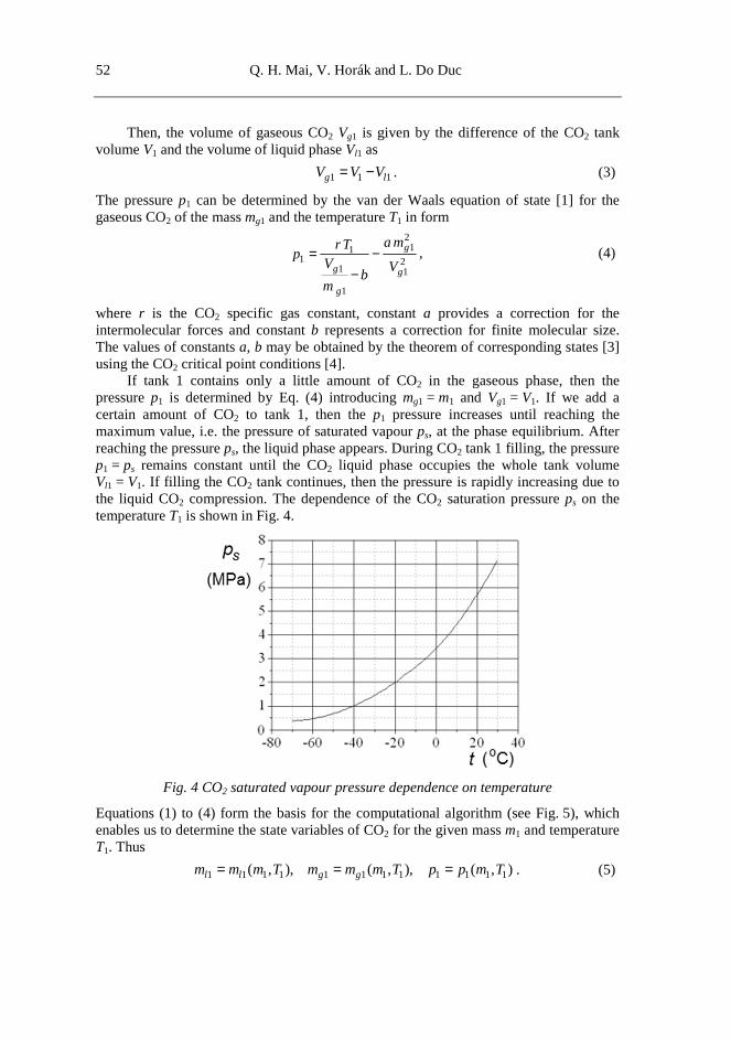
If tank 1 contains only a little amount of CO2 in the gaseous phase, then the pressure p1 is determined by Eq. (4) introducing mg1 = m1 and Vg1 = V1. If we add a certain amount of CO2 to tank 1, then the p1 pressure increases until reaching the maximum value, i.e. the pressure of saturated vapour ps, at the phase equilibrium. After reaching the pressure ps, the liquid phase appears. During CO2 tank 1 filling, the pressure p1 = ps remains constant until the CO2 liquid phase occupies the whole tank volume Vl1 = V1. If filling the CO2 tank continues, then the pressure is rapidly increasing due to the liquid CO2 compression. The dependence of the CO2 saturation pressure ps on the temperature T1 is shown in Fig. 4.
Fig. 4 CO2 saturated vapour pressure dependence on temperature
Equations (1) to (4) form the basis for the computational algorithm (see Fig. 5), which enables us to determine the state variables of CO2 for the given mass m1 and temperature T1. Thus
1 1 1 1 1 1 1 1 1 1 1 1( , ), ( , ), ( , )l l g gm m m T m m m T p p m T= = = . (5)

53 53
Sound Effect of RPG-7 Anti-Tank Grenade Launcher for Shooting Training
Fig. 5 Computational algorithm for determining the CO2 state variables
By using this computational algorithm for the given CO2 tank of volume V1 = 185 ml, we can obtain the pressure p1 dependence on the two-phase fluid mass m1 for various temperatures T1 as shown in Fig. 6a. Furthermore, the pressure p1 and the mass fractions of gaseous xmg1 and liquid xml1 phases related to the two-phase fluid mass m1 at the temperature t1 = 15 °C are shown in Fig. 6b.
Fig. 6 Pressure p1 and mass fractions of gaseous xmg1 and liquid xml1 phases related to the mass m1: a) for various temperatures t1, b) at temperature t1 = 15 °C
54 Q. H. Mai, V. Horák and L. Do Duc
Assuming that valve 3 of the flow area A is immediately opened (see Fig. 3), the mass flow rate of the gaseous phase through valve 3 is calculated as the adiabatic discharge of an ideal gas from tank 1 into chamber 2 neglecting flow losses by applying the Saint-Venant and Wantzel’s formula [7-8] for CO2 as
2 12
11 2 2 2
1 1 1 11
2 12
1 1 11 2
1 1
2 2for
1 1
2 2 2 2for
1 1 1 1
g
p p p p
r T p p pdm
m Adt
p p
r T p
κ κκ κ κ
κ κκ κ κ
κκ κ
κκ κ κ κ
+−
+− − −
− ≥ − + = =
− < − + + +
& (6)
Where, m& is the mass flow rate between CO2 tank 1 and the explosion chamber 2 for
the pressure drop p2/p1 and κ = cp /cV ≈ 1.3 is the adiabatic exponent, that is the ratio of the constant-pressure and the constant-volume specific heat capacities of gaseous CO2.
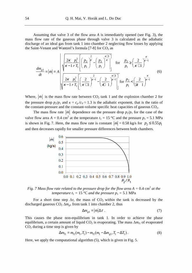
The mass flow rate m& dependence on the pressure drop p2/p1 for the case of the
valve flow area A = 0.4 cm2 at the temperature t1 = 15 °C and the pressure p1 = 5.1 MPa is shown in Fig. 7. Here, the mass flow rate is constant m& = 0.58 kg/s for 2 10.55p p≤
and then decreases rapidly for smaller pressure differences between both chambers.
Fig. 7 Mass flow rate related to the pressure drop for the flow area A = 0.4 cm2 at the temperature t1 = 15 °C and the pressure p1 = 5.1 MPa
For a short time step ∆τ, the mass of CO2 within the tank is decreased by the discharged gaseous CO2 ∆mg1 from tank 1 into chamber 2, thus
1gm m τ∆ = ∆& . (7)
This causes the phase non-equilibrium in tank 1. In order to achieve the phase equilibrium, a certain amount of liquid CO2 is evaporating. The mass ∆ml1 of evaporated CO2 during a time step is given by
1 1 1 1 1 1 1 1 1( , ) ( , )l l l gm m m T m m m T T∆ = − − ∆ − ∆ . (8)
Here, we apply the computational algorithm (5), which is given in Fig. 5.

55 55
Sound Effect of RPG-7 Anti-Tank Grenade Launcher for Shooting Training
Due to the CO2 vaporization, the temperature T1 of the thermodynamic system including: the CO2 gaseous and liquid phases and walls of the CO2 tank 1, decreases. Assuming the high convective heat transfer coefficient for a boiling liquid and the high thermal conductivity of a walls material and assuming the same temperature within the whole system, the temperature drop ∆T1 can be determined from the energy balance of the thermodynamic system in form
( )1 1
11 1
l
l pl g pg w w
L T mT
m c m c m c
∆∆ =
+ +, (9)
where L(T1) is the CO2 specific latent heat of vaporization at temperature T1, ml1 and mg1 are masses of liquid and gaseous phases, mw is the mass of CO2 tank and cpl, cpg, cw are corresponding specific heat capacities.
Equations (8) and (9) enable us to determine the change in the liquid CO2 mass ml1 and the change in the temperature ∆T1 for the time step ∆τ using a numerical method.
The mass of gaseous CO2 in the explosion chamber 2 during its pressurization is
( )02 2
0
dg gm m mτ
τ= + ∫ & , (10)
where ( )02gm is the initial mass of gaseous CO2 in the explosion chamber 2 before the
control valve 3 opening. The gaseous CO2 flowing into the explosion chamber 2 causes an increase in the
pressure p2, which can be determined by the van der Waals equation of state in analogy with Eq. (4) as
2
222 2
2 2
2
g
g
a mrTp
V Vbm
= −−
, (11)
where V2 is the volume of the explosion chamber 2 and T2 is the gas temperature in this chamber.
The temperature T2 can be determined by applying the principle of conservation of energy to the thermodynamic system [9] for the explosion chamber 2, if the filling is in the gaseous phase and the temperature change is not too great, thus
( ) ( )0 012 2
02
2
dV pg
g V
m c T m c T
Tm c
ττ+
=∫ &
, (12)
where the upper subscript (0) denotes the initial values of variables before the control valve opening.
3. Results of Solution of the Explosion Chamber Pressurising It is seen from Eqs (9) and (10), that the main factor causing the pressure increase in the explosion chamber is the added mass of gaseous CO2 which flowing through the control valve. The added mass flow rate m& is proportional to the valve flow area A, the
pressure p1 and temperature T1 in the CO2 tank, and the pressure drop between both chambers by Eq. (6). If the CO2 tank still contains the liquid state of CO2 then the

56 Q. H. Mai, V. Horák and L. Do Duc
vaporization of CO2 occurs to compensate the gas discharge and to keep the phase equilibrium. The mass of evaporated CO2 is given by Eq. (8) and the temperature drop ∆T1 is determined by Eq. (9). When the all liquid CO2 is evaporated, then the discharging process continues as the adiabatic gas flow between both chambers. The described problem can be solved using the computational algorithm which is given in Fig. 8.
Fig. 8 Computational algorithm for solution of thermodynamic processes
The input data of the solution for the observed case of the device for simulation of the RPG-7 sound effect are as follows:
( ) ( ) ( ) ( )0 0 0 02 o1 21 1 2 250 g, 185 ml, 1500 ml, 0.4 cm , 15 C, 0.1 MPam V V A t t p= = = = = = = .
The computation ends when the same pressure in the CO2 tank and the explosion chamber is reached. The obtained results of the solution of the ongoing thermodynamic processes for the given example are clearly shown in Fig. 9.

57 57
Sound Effect of RPG-7 Anti-Tank Grenade Launcher for Shooting Training
Fig. 9 Time courses of state variables in CO2 tank and explosion chamber
It can be observed in Fig. 9a that the mass of CO2 liquid phase ml1 decreases to zero at the first 70 ms due to its vaporization. The mass of gaseous phase mg2 in the explosion chamber is increasing, but the rate of this increase is smaller when the liquid phase in the CO2 tank is entirely vaporized. This is the reason for the increase in pressure p2 in the explosion chamber, as seen in Fig. 9b. The pressure p1 decreases, although the tank still contains the liquid CO2, due to the temperature t1 decrease (Fig. 9c). The pressure p1 drops significantly after the moment when the liquid phase in the CO2 tank is entirely vaporized. It is seen in Fig. 9b that the time of explosion Ex occurs 58 ms after the moment of the valve opening, when the pressure p2 within the explosion chamber reaches the value of 1.2 MPa.
Results obtained using the described computational algorithm enable us to observe influence of changes in various design parameters or initial conditions. The results of such calculations are presented in Fig. 10.
Fig. 10 Influence of some parameters on the pressure in explosion chamber:
a) influence of valve flow area A, b) influence of initial mass ( )01m ,
c) influence of initial temperature ( )01t and CO2 mass ( )0
1m

58 Q. H. Mai, V. Horák and L. Do Duc
The impact of the size of the valve flow area A is shown in Fig. 10a. It is seen that the larger the flow area A is, the greater is the increase rate of pressure p2 in the explosion chamber and then the time for reaching the PET bottle burst pressure 1.2 MPa is shorter.
The influence of the initial mass ( )01m of the CO2 tank filling is shown in Fig. 10b.
The maximum pressure p2max in the explosion chamber increases with the initial mass ( )01m of CO2, but the rate of pressure rise is almost independent of the initial mass of the
CO2 for greater values of initial mass. It is seen that the initial mass of the CO2 must be greater than 30 g to reach the PET bottle burst pressure 1.2 MPa. If we want to reduce the time delay in reaching the burst pressure, enlarging the valve flow area A is a better solution compared with increasing the initial mass of CO2.
The dependence of the maximum pressure p2max reached in the explosion chamber
related to the initial mass ( )01m of CO2 for various initial temperatures ( )0
1t is given in Fig.
10 c). Here, it is illustrated that the maximum reached pressure increases with the initial
mass ( )01m and the initial temperature ( )0
1t . The rate of the pressure p2max increase in
relation to the initial mass drops significantly at low initial temperatures, because the pressure of CO2 saturated vapour ps decreases rapidly with the drop in temperature (see Fig. 4). Therefore, the entire vaporization of CO2 in the liquid phase does not occur if the pressure equilibrium of both chambers is achieved at low working temperatures.
Due to the limited space for integration of the developed device for simulating the sound effects into the body of the PG-7 practice grenade, the maximum possible volume of CO2 tank is V1max = 185 ml. Regarding to the safety standard [10], the CO2 tanks have never been filled more than 67 % of the available volume. Therefore, the maximum
allowed mass of CO2 filling within this tank is ( )01max 124 gm = .
Another important design parameter is the explosion chamber volume V2 which includes the volume of a PET bottle. The dependence of the maximum pressure p2max reached in the explosion chamber related to the size of its volume V2 for various initial
temperatures ( )01t is given in Fig. 11.
Fig. 11 Maximum pressure p2max in explosion chamber related to its volume V2 for
various initial temperatures ( )01t and mass of CO2 filling ( )0
1max 124m g=

59 59
Sound Effect of RPG-7 Anti-Tank Grenade Launcher for Shooting Training
This diagram allows us to choose the appropriate volume of the explosion chamber. The volume and the burst pressure of used PET bottle determine the intensity level of desired sound effect to meet the requirements for a military training.
The accuracy of the presented mathematical model was verified experimentally by measuring the value of maximum pressure p2max reached in the explosion chamber using a manometer. The results for various masses of CO2 filling are shown in Tab. 1. It is seen that the results of theoretical solution correspond quite well with experimental measurements.
Tab. 1 Comparison of calculated and measured values of maximum pressure in explosion chamber for various masses of CO2 filling
Mass of CO2 filling ( )01max [g]m
10 30 60 90 120
Calculated values p2max [MPa]
0.45 1.14 2.03 2.38 2.49
Measured values p2max [MPa]
0.43 1.1 1.95 2.25 2.35
Difference [%] 4.7 3.6 4.1 5.8 6.0
4. Conclusion In this study, the mathematical model for calculating the pressure rise within the explosion chamber has been developed. Results obtained using this algorithm allow us to analyse various influences of changes in some design parameters or initial operating conditions. This model is the base for the design of the device that simulates the sound effects of the RPG-7 anti-tank grenade launching during the combat shooting training.
The accuracy of the presented mathematical model was verified experimentally by measuring on the prototype of this device. It can be stated that the results of theoretical solution correspond quite well with experimental measurements.
With regard to the experience with testing of the prototype and the given model analysis, the future improvement and development of this mathematical model is expected by involving the phenomena of the heat transfer and the two-phase fluid flows. The heat transfer between the two-phase fluid [11] and the CO2 tank walls influences the fluid temperature which is a significant parameter in the CO2 phase equilibrium. Furthermore, the assumption of the CO2 discharge as an ideal gas flow is not very relevant to the observed problem. Therefore, the isentropic flow of the two-phase fluid, involving the sound velocity of the two-phase CO2 mixture [12], should also be included in future studies.
Acknowledgement The work presented in this article has been supported by the institutional funding PRO K216 “Support of Research, Experimental Development, and Innovation in Mechanical Engineering” and by the Specific Research Support Project of the Faculty of Military Technology SV K201.
60 Q. H. Mai, V. Horák and L. Do Duc
References [1] Voluntary Design Guidelines for Designated PET Bottles. Tokyo: Council for PET
Bottle Recycling, 2011. [cited 2014-02-12]. Available from: <http://www.petbottle-rec.gr.jp/english/design.html>.
[2] ISO 1043-1:2001 Plastics – Symbols and abbreviated terms − Part 1: Basic polymers and their special characteristics.
[3] HORÁK, V. and KULISH, VV. Thermodynamics. Brno: University of Defence, 2011, 102 p.
[4] VARGAFTIK, NB., Handbook on the Thermophysical Properties of Liquids and Gases [In Russian]. Moskva: Nauka, 1972, p. 167-210.
[5] Carbon dioxide data [on line] [cited 2014-03-17]. Available from: <http://en.wikipedia.org/wiki/Carbon_dioxide_data>.
[6] Thermodynamic Properties of R744 [on line] [cited 2014-03-17]. Available from: <http://www.ohio.edu/mechanical/thermo/property_tables/CO2/index.html>.
[7] ARSENJEV, SL., LOZOVITSKI, IB. and SIRIK, YP. The Flowing System Gasdynamics. Part 3: Saint-Venant – Wantzel’s formula modern form. February 2003, 3 p. [cited 2014-02-02]. Available from: <http://arXiv:physics/0302038>
[8] POTTER, MC. and WIGGERT, DC. Mechanics of Fluids, 2nd ed. New Jersey: Prentice Hall, 1997, 689 p.
[9] ORLOV, BV. and MAZING, GJ. Thermodynamic and Ballistic Design Fundamentals of Solid-propellant Rocket [In Russian]. Moskva: Mashinostroenie, 1968, 430 p.
[10] WHO Technical Specifications, Cryosurgical equipment for the treatment of precancerous cervical lesions and prevention of cervical cancer. Geneva: World Health Organization 2012, 60 p.
[11] LUND H. and AURSAND, P. Two-Phase Flow of CO2 with Phase Transfer. (The 6th Trondheim Conference on CO2 Capture, Transport and Storage). Energy Procedia, vol. 23, 2012, p. 246-255.
[12] LUND H. and FLÅTTEN, T. Equilibrium conditions and sound velocities in two-phase flows. SIAM Annual Meeting. Pittsburgh: July 2010, 15 p. [cited 2014-02-02]. Available from: <http://www.sintef.no/project/CO2%20Dynamics/publications/lund_an10.pdf>
Related Documents