Some Supersonic Aerodynamics W.H. Mason Configuration Aerodynamics Class Grumman Tribody Concept – from 1978 Company Calendar

Welcome message from author
This document is posted to help you gain knowledge. Please leave a comment to let me know what you think about it! Share it to your friends and learn new things together.
Transcript
Some Supersonic Aerodynamics
W.H. Mason Configuration Aerodynamics Class
Grumman Tribody Concept – from 1978 Company Calendar

The Key Topics• Brief history of serious supersonic airplanes
– There aren’t many!• The Challenge
– L/D, CD0 trends, the sonic boom• Linear theory as a starting point:
– Volumetric Drag– Drag Due to Lift
• The ac shift and cg control• The Oblique Wing• Aero/Propulsion integration• Some nonlinear aero considerations• The SST development work• Brief review of computational methods• Possible future developments

Are “Supersonic Fighters” Really Supersonic?• If your car’s speedometer goes to 120 mph, do you actually
go that fast?• The official F-14A supersonic missions (max Mach 2.4)
– CAP (Combat Air Patrol)• 150 miles subsonic cruise to station• Loiter• Accel, M = 0.7 to 1.35, then dash 25nm
– 4 ½ minutes and 50nm total• Then, head home or to a tanker
– DLI (Deck Launch Intercept)• Energy climb to 35K ft., M = 1.5 (4 minutes)• 6 minutes at 1.5 (out 125-130nm)• 2 minutes combat (slows down fast)After 12 minutes, must head home or to a tanker

Very few real supersonic airplanes• 1956: the B-58 (L/Dmax = 4.5)
– In 1962: Mach 2 for 30 minutes
• 1962: the A-12 (SR-71 in ’64) (L/Dmax = 6.6)– 1st supersonic flight, May 4, 1962– 1st flight to exceed Mach 3, July 20, 1963
• 1964: the XB-70 (L/Dmax = 7.2)– In 1966: flew Mach 3 for 33 minutes
• 1968: the TU-144– 1st flight: Dec. 31, 1968
• 1969: the Concorde (L/Dmax = 7.4)– 1st flight, March 2, 1969
• 1990: the YF-22 and YF-23 (supercruisers)– YF-22: 1st flt. Sept. 29, 1990, F-22 1st flt. Sept. 7, 1997– YF-23: 1st flt. Aug. 27, 1990

The B-58
See Erickson, “Flight Characteristics of the B58 Mach 2 Bomber,” J. of the Royal Aero. Soc., Nov. 1962, Vol. 66, No. 623, pp 665-671
Static margin, 3% for longitudinal stability, > 3% needed for directional stability margin in the engine out case. An ARI (Aileron-Rudder Interconnect) was used to cancel the yawing moment due to aileron deflection.
Used GE J79 engines

SR-71• See Ben Rich’s paper• Heating issues make it “hypersonic”• Used the P&W J58 turboramjet
See Peter W. Merlin, Design and Development of the Blackbird, AIAA Library of Flight Series, 2008

XB-70• The single remaining (of 2)
XB-70 is at the USAF Museum in Dayton, Ohio
• 2nd airplane collision with F-104, June 8, 1966
Wingtips deflected down at high speed: almost no ac shift, sub- to supersonic speeds
Retired: Feb. 4, 1969
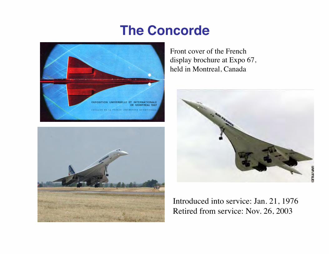
The ConcordeFront cover of the French display brochure at Expo 67, held in Montreal, Canada
Introduced into service: Jan. 21, 1976Retired from service: Nov. 26, 2003

Reality
Do you think this “supersonic” fighter can fly supersonic with this load??

The Challenge• Entirely different physics (hyperbolic vs elliptic pde - remember?)
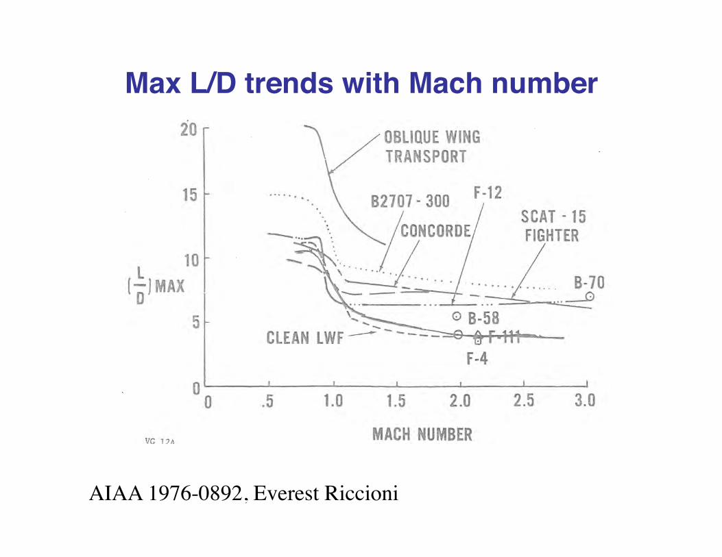
Max L/D trends with Mach number
AIAA 1976-0892, Everest Riccioni
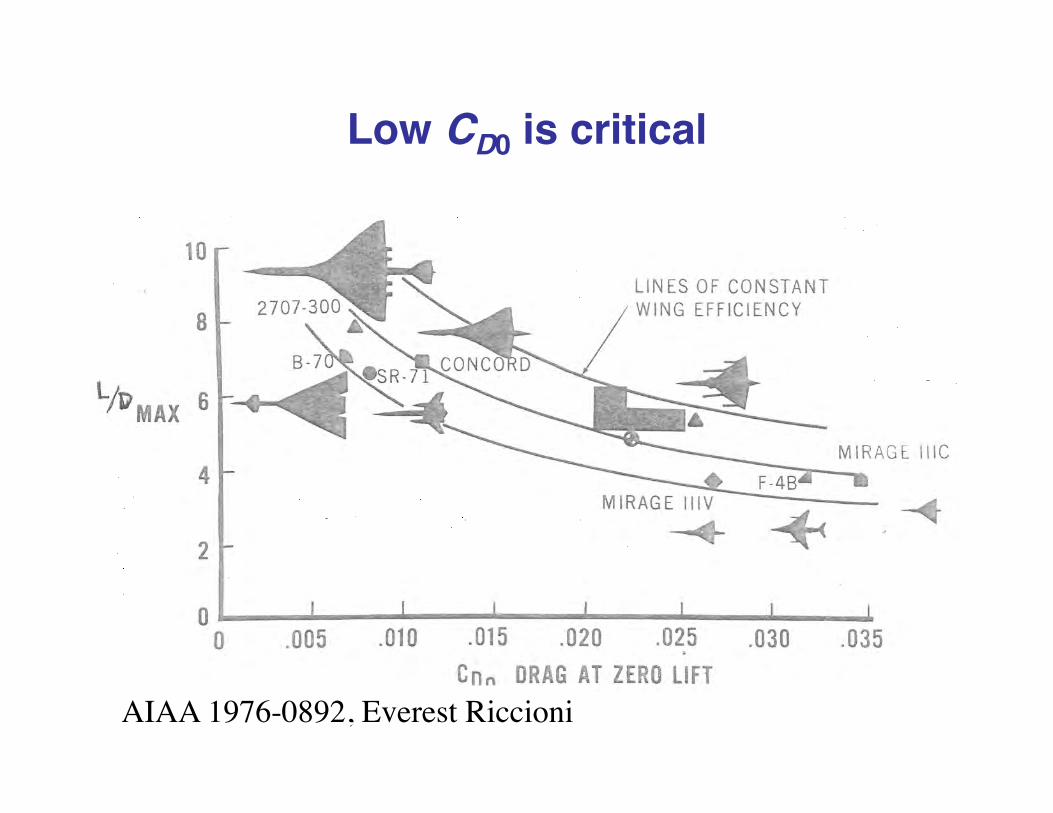
Low CD0 is critical
AIAA 1976-0892, Everest Riccioni

Typical CD0 trendsfor Fighters
From Nicolai, Fundamentals of Aircraft Design

Understanding Drag• Break into zero lift and drag due to lift
– Use linear theory to provide conceptual basis for your design thinking
The real problem
You will probably never have enough thrust to reach L/Dmax • at cruise, CD0 dominates
Wave Drag
• Primarily due to volume, but also lift• Minimum drag area distributions and
fineness ratio are your primary tools– We talked about the area rule discussing drag in
general earlier

Fineness Ratio, l/d: A powerful way to reduce wave drag
0.00
0.05
0.10
0.15
0.20
4 6 8 10 12 14 16 18 20
D/q
l/d
V2/3
A Sears-Haack body, with Volume V
l/d, the length to diameter ratio
Note: using the drag, D, anddynamic pressure, q, removesthe reference area issue
Based on slender body theory

Wave dragand frictiondrag combinedFrom “Applied Aerodynamics and Flight Mechanics,” by W. Bailey Oswald, Journal of the Aeronautical Sciences, May 1956.
Mason did this andthen found it had already been done,but it is a good exercise
Note the difference in fineness ratio for min drag for the two cases

Min Wave Drag of Axi-body with zero base area:
Radius Given Volume & Length
0.00
0.01
0.02
0.03
0.04
0.05
0.06
0.07
0.00 0.20 0.40 0.60 0.80 1.00
r/l
x/l
fineness ratio of 8
Sears Haack Body Radius Distribution
Dq=128π
Vol2
l 4
Note: No Mach number dependence with the slender body theory used here.

Min Drag Radius for Axi-bodyGiven Base Area/Length
0.00
0.05
0.10
0.15
0.20
0.00 0.20 0.40 0.60 0.80 1.00
r/l
x/l
von Karman Ogive Radius
Dq=4πS(l)2
l2
Note: No Mach number dependence with the slender body theory used here.
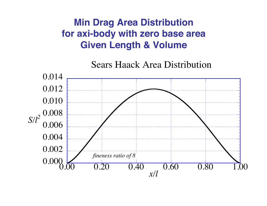
Min Drag Area Distribution for axi-body with zero base area
Given Length & Volume
0.0000.0020.0040.0060.0080.0100.0120.014
0.00 0.20 0.40 0.60 0.80 1.00
S/l2
x/l
fineness ratio of 8
Sears Haack Area Distribution

Min Drag Area Distribution for Axi-body Given Base Area and Length
0.000.020.040.060.080.100.120.14
0.00 0.20 0.40 0.60 0.80 1.00
S/l2
x/l
von Karman Ogive Area Distribution

The strange story of the LE radius
The slope at the nose is 90°, but the leading edge radius is zero!
Both the Sears-Haack body and the von Karman ogive behave like a power law body with an exponent, n, of 0.75 at the nose.
rl≈
xl
"#$
%&'
n
AIAA paper 92-2727

Demo Wave Drag Interactive Toy
Available on http://www.aoe.vt.edu/~mason/Mason_f/MRsoft.html
Note: opening up the base allows a reduction in drag

Wave drag of slender wing planar surfaces relative to the Sears-Haack body
From D. Küchemann, The Aerodynamic Design of Aircraft, Pergamon Press, 1978
K0 is drag relative to Sears-HaackYou can get less than one!
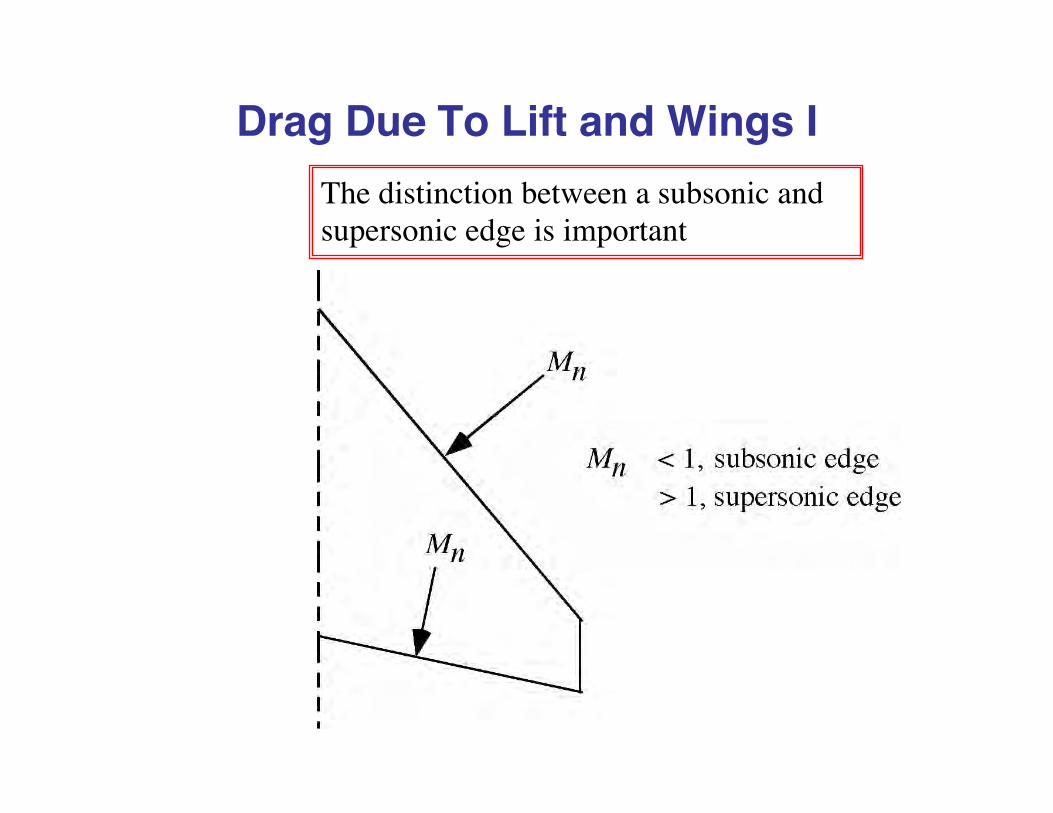
Drag Due To Lift and Wings IThe distinction between a subsonic and supersonic edge is important

Mach number zones of influenceFor a subsonic edge, the top and bottom surfaces can communicate
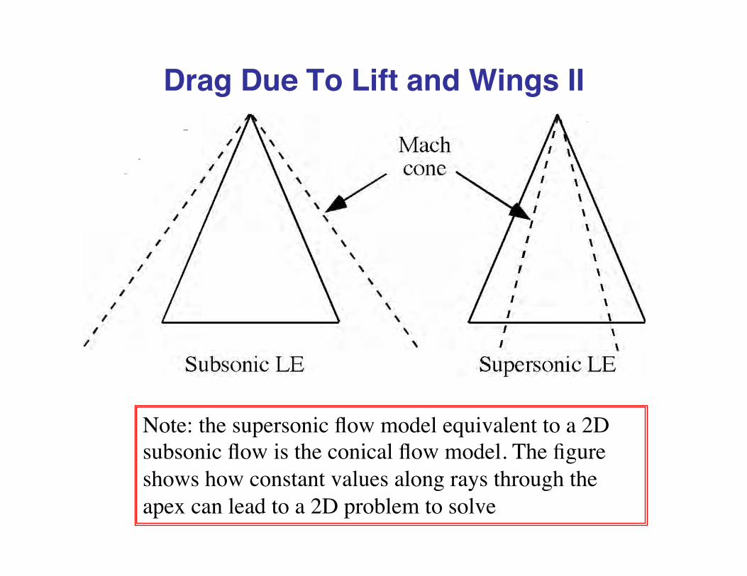
Drag Due To Lift and Wings II
Note: the supersonic flow model equivalent to a 2D subsonic flow is the conical flow model. The figure shows how constant values along rays through the apex can lead to a 2D problem to solve

Spanwise Pressure Distributions
Subsonic LE Supersonic LE
0.0
0.5
1.0
1.5
2.0
-1.00 -0.50 0.00 0.50 1.00
ΔCp/CL
y/(b/2)Leadingedge
LeadingedgeCenterline
0.0
0.5
1.0
1.5
2.0
-1.00 -0.50 0.00 0.50 1.00
ΔCp/CL
y/(b/2)Leadingedge
LeadingedgeCenterline
edge of Mach cone
Delta Cp on an uncambered delta wing (conical flow). Implies the pressures at the trailing edge don’t have to come together as in subsonics, the consequence of a supersonic TE
• Subsonic edges CAN generate leading edge suction• Supersonic edges CANNOT produce leading edge suction
∞ ∞
Note: conical flow means the spanwise pressure distributions look the same at every longitudinal station

The Arrow Wing
arrow.f can be used to find the supersonic aerodynamics of these wings: http://www.aoe.vt.edu/~mason/Mason_f/MRsoft.html

The Arrow Wing Lift Curve Slope(code on class website)
Formulas available in R.T. Jones and D. Cohen, High-Speed Wing Theory, Princeton University Press, Princeton, NJ, 1957
2.5
3.0
3.5
4.0
4.5
0.4 0.6 0.8 1.0 1.2 1.4 1.6
βCLα
m = βcot(ΛLE
)
computation from arrow.f
notch ratio = 0(pure delta)
notch ratio = 0.2
SupersonicLeading Edge
SubsonicLeading Edge

Unwrapping the theoretical nondimensionalization

Arrow Wing Drag (code on class website)
0.15
0.20
0.25
0.30
0.35
0.40
0.40 0.60 0.80 1.00 1.20 1.40 1.60
Δ CD/(βCL2)
m = βcot(ΛLE
)
notch ratio = 0.0
notch ratio = 0.2
computation from arrow.f
100 % LE suctionSupersonic
Leading EdgeSubsonic
Leading Edge
0 % LE suction
Formulas available in R.T. Jones and D. Cohen, High-Speed Wing Theory, Princeton University Press, Princeton, NJ, 1957

Unwrapping the theoretical nondimensionalization
0.00
0.10
0.20
0.30
0.40
0.50
0.0 0.50 1.0 1.5 2.0 2.5
Example of Drag Due to Lift with Mach Number
K
M
100% LES
0% LES
E = 0.9= 1.0
0% LES
Supersonic Calcs using arrow from class software site
60° LE sweep, 20° TE Sweep Arrow Wing
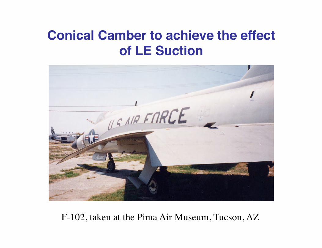
Conical Camber to achieve the effect of LE Suction
F-102, taken at the Pima Air Museum, Tucson, AZ

The Application of the concept
John Boyd, a Hokie, was also a key contributor at NACA Ames
Conical Camber was used on the F-102, the F-106and the B-58 Hustler, as well as the F-15
Charles Hall, inventor, looking at a WT model with conical camber.
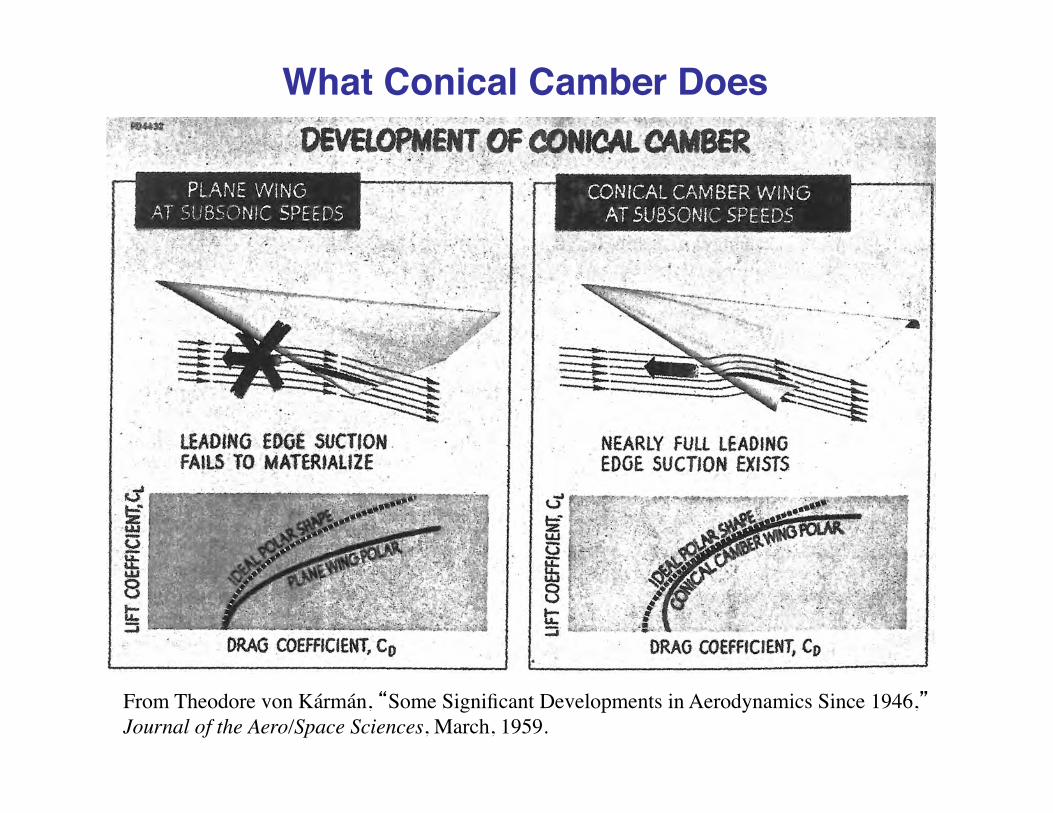
What Conical Camber Does
From Theodore von Kármán, “Some Significant Developments in Aerodynamics Since 1946,”Journal of the Aero/Space Sciences, March, 1959.
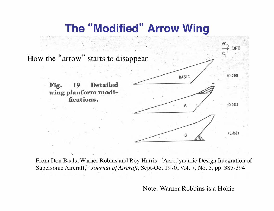
The “Modified” Arrow Wing
From Don Baals, Warner Robins and Roy Harris, “Aerodynamic Design Integration of Supersonic Aircraft,” Journal of Aircraft, Sept-Oct 1970, Vol. 7, No. 5, pp. 385-394
How the “arrow” starts to disappear
Note: Warner Robbins is a Hokie

The ac shiftAll supersonic airplanes shift fuel to control the static margin
From the AIAA Concorde Case study
This shows why a pure delta wing isn’t a great idea

The Concorde cg travelNote narrow range everywhere, the ref chord is the root chord for the Concorde
Figure courtesy of British Aerospace

ac shift IIA double delta planform reduces the shift
From NASA TN D-3581, October 1966, by John Lamar and Joe Alford

ac shift III
Why?Hypotheses by Ben Rich and Joe Alford• The inboard wing is more highly swept and the CLα is insensitive to Mach number• The outboard wing has less sweep and the CLα decreases with Mach number
Read: NASA TN D-3581, October 1966, by John Lamar and Joe Alford Ben Rich, Journal of Aircraft, July 1974
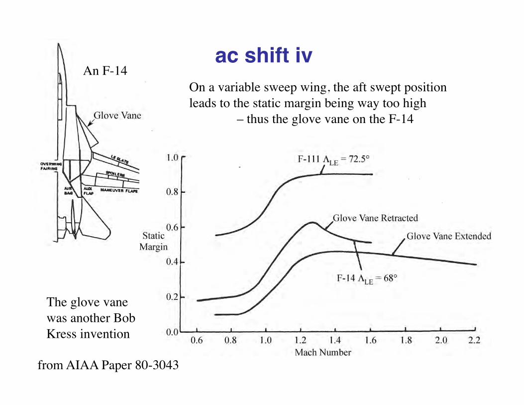
ac shift iv
The glove vane was another Bob Kress invention
On a variable sweep wing, the aft swept position leads to the static margin being way too high
– thus the glove vane on the F-14
from AIAA Paper 80-3043
An F-14

But, there is one other important concept: The Oblique WingDue to R.T. Jones
AD-1 1st Flight: Dec 21, 1979Last flight: Aug. 7, 1982
Photo from NASA Dryden photo library
Photo take outside the NASA Ames Full Scale WT
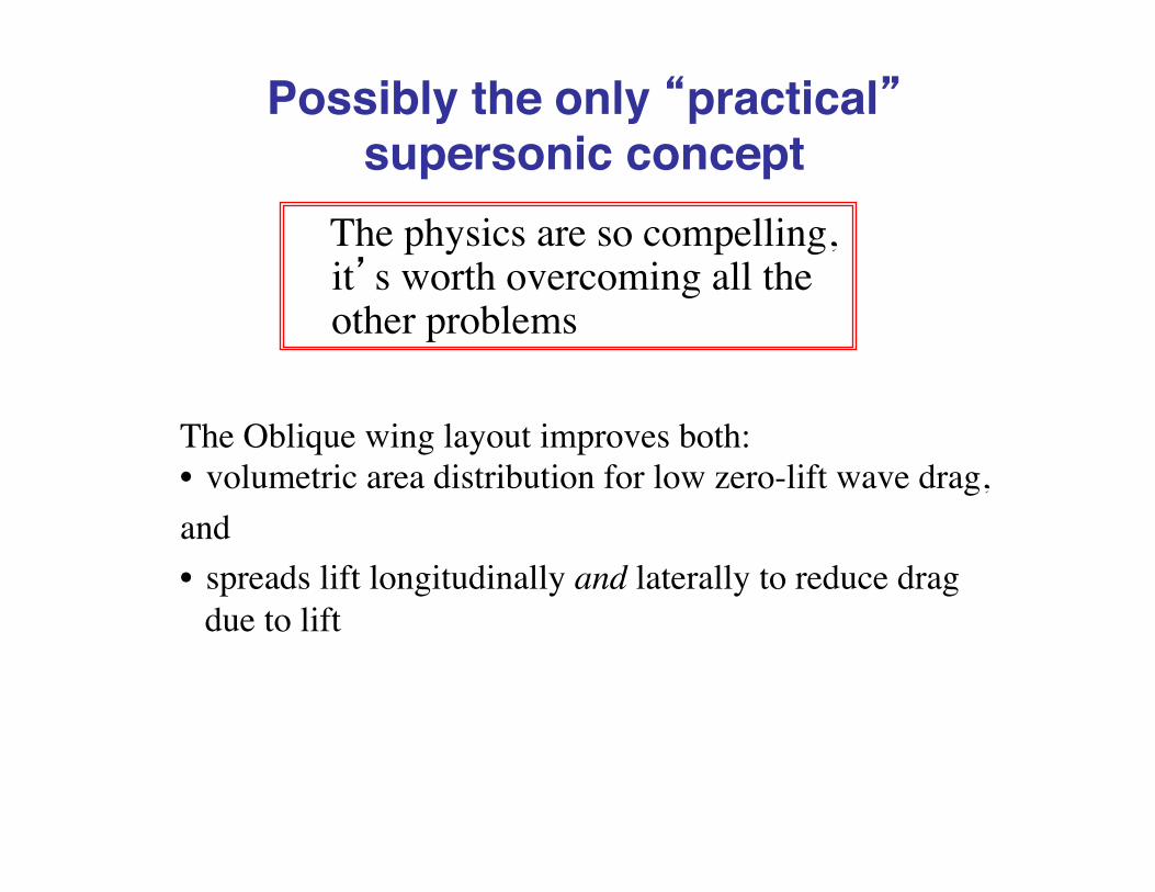
Possibly the only “practical” supersonic concept
The physics are so compelling, it’s worth overcoming all the other problems
The Oblique wing layout improves both: • volumetric area distribution for low zero-lift wave drag,and• spreads lift longitudinally and laterally to reduce drag
due to lift

Sometimes a homework problemElizabeth Eaton, Spring 2006
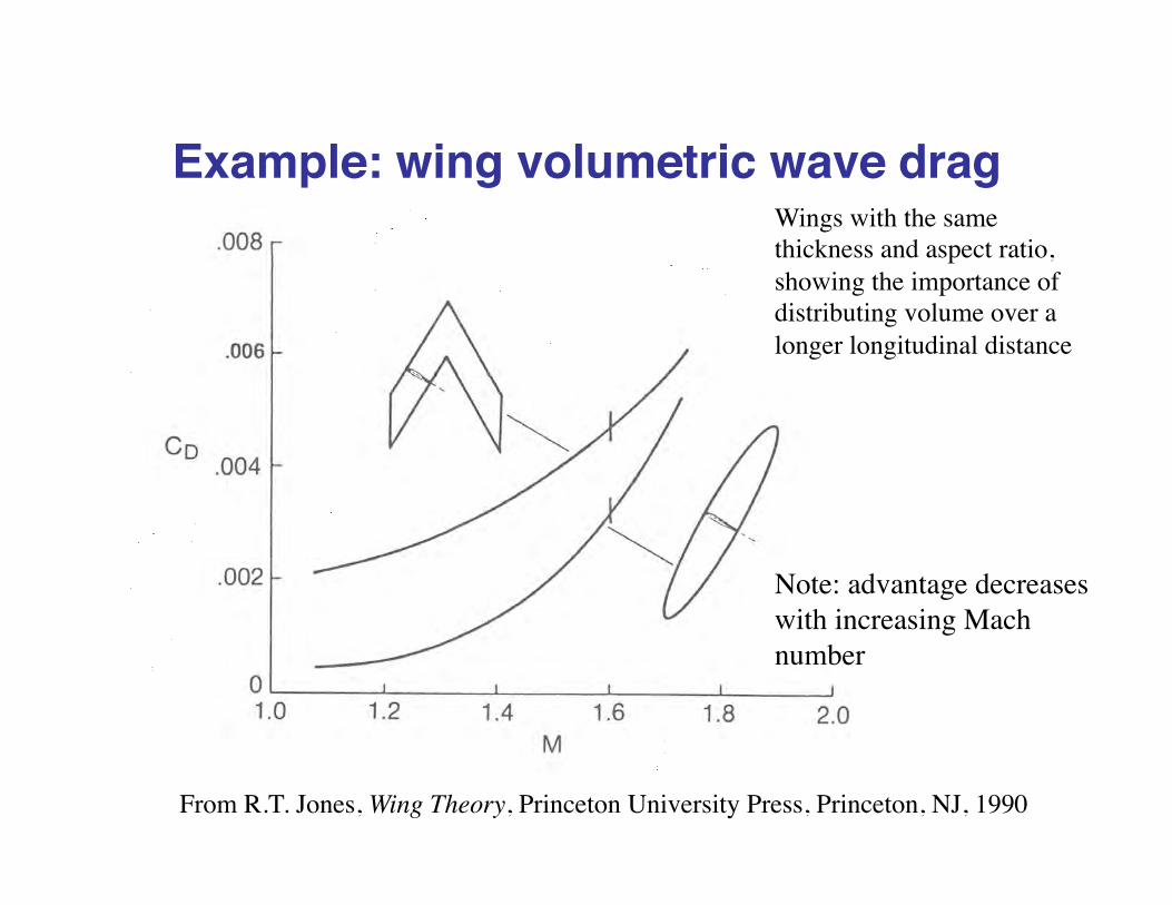
Example: wing volumetric wave drag
From R.T. Jones, Wing Theory, Princeton University Press, Princeton, NJ, 1990
Wings with the same thickness and aspect ratio, showing the importance of distributing volume over a longer longitudinal distance
Note: advantage decreases with increasing Mach number

The AD-1 and a flying wing UAV
The NASA AD-1Stanford Flying Oblique
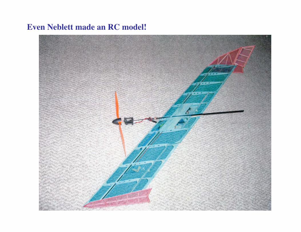
Even Neblett made an RC model!

Aero-Propulsion Integrationbecomes a critical consideration
From Don Baals, Warner Robins and Roy Harris, “Aerodynamic Design Integration of Supersonic Aircraft,” Journal of Aircraft, Sept-Oct 1970, Vol. 7, No. 5, pp. 385-394
Example: details are critical to optimizing the design

The computations storyLinear Theory• For volumetric wave drag: The Harris Code, using the Eminton-Lord
integral integration scheme
• The common input, the so-called Craidon input format• Lifting surfaces panels:
– For the US SST, The Boeing system of panel methods for both analysis and design
– Later, Harry Carlson’s Codes Aero2S and WINGDES• The concept of “attainable leading edge suction” introduced to
include nonlinear aero in a “linear” methodology
Nonlinear Theory• Space marching Euler and PNS – finally RANS
An irony: to a very good approximation a flat surface with 100% leading edge suction defines the minimum drag due to lift you can get.
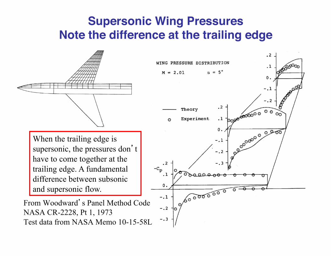
Supersonic Wing PressuresNote the difference at the trailing edge
When the trailing edge is supersonic, the pressures don’t have to come together at the trailing edge. A fundamental difference between subsonic and supersonic flow.
From Woodward’s Panel Method Code NASA CR-2228, Pt 1, 1973 Test data from NASA Memo 10-15-58L

Wave Drag - The Harris CodeNeeds the geometry to compute the integral.
Harris, NASA TM X-947, 1964. Uses the Craidon GeometryawaveFileMake.m by Prof. Lowe helps you make the input
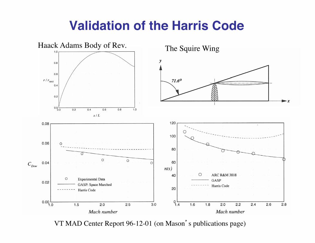
Validation of the Harris CodeHaack Adams Body of Rev. The Squire Wing
VT MAD Center Report 96-12-01 (on Mason’s publications page)

Modeling a Configuration in the Harris Code
A Grumman Design Study w/WT Model for the Air Force

The ATTAC Harris Wave Drag Model
Use “pods” to represent area
Wave drag model by Ron Hendrickson, Grumman

A Drag Polar Comparison
Comparison of Linear Theories with Eulerand RANS for a supersonic transport
Note: PNS stands for Parabolized Navier Stokes
Comparison made by Duane KnillFrom VT Mad Ctr Report 96-12-01

Supersonic wings – almost flat, �in fact negative camber on the F-16
From AIAA Case Study on the F-16 flight control system

The US SST Program• Started in Response to British/French and USSR
Supersonic Transport Programs• Too big for one company, a national program funded by
the US and administered mainly by the FAA!?• Aug. 15, 1963: FAA Issues RFP• May 15, 1964: Gov’t selects Boeing and Lockheed and
GE & P&W to compete for final concept– Lockheed proposes a double delta– Boeing proposes a variable sweep wing
• Dec. 31, 1966: Boeing & GE selected• Oct. 21, 1968: Boeing abandons variable sweep• March 24, 1971: Program cancelled

Comparison of concepts
Walter C. Swan, “A Review of the Configuration Development of the U.S. Supersonic Transport,” 11th Anglo-American Aeronautical Conference, London, Sept., 1969.

But first, a most bizarre variable sweep concept, the 2707-200!
M. Leroy Spearman, “The Evolution of the High-Speed Civil Transport,” NASA TM 109089, Feb., 1994
Ramps bring air to the engines from above the wing, and shield the engine inlets from landing gear spray/wake!
Engines mounted on horizontal tail!

That drawing does not do the 2707-200 justice!
Looks sleek in cruise configuration
A nightmare in TO/Ldg Config.
Mason made this model in 1969, when it appeared

Aeroelasticity – can’t neglect! Aeroelastic deformation lessons learned on Boeing’s 1960s/early 70s
US SST design - from Kumar Bhatia AIAA Paper 93-1478
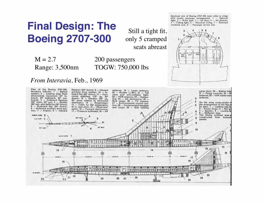
Final Design: The Boeing 2707-300
Still a tight fit, only 5 cramped
seats abreast
From Interavia, Feb., 1969
M = 2.7 200 passengersRange: 3,500nm TOGW: 750,000 lbs

Example: linear theory breakdown at “high” lift and a wing concept development program
NASA CR 3763
Rudy Meyer at Grumman identifies a problem(and a solution)

The physics of the breakdownThe physics The implications for theory
NASA CR 3763, 1983
If the crossflow is supercritical, need to address, just as for 2D transonic flow
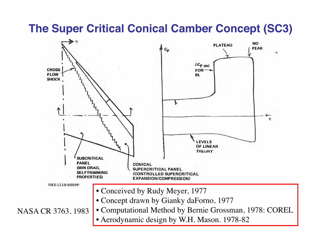
The Super Critical Conical Camber Concept (SC3)
NASA CR 3763, 1983
• Conceived by Rudy Meyer, 1977• Concept drawn by Gianky daForno, 1977• Computational Method by Bernie Grossman, 1978: COREL• Aerodynamic design by W.H. Mason. 1978-82
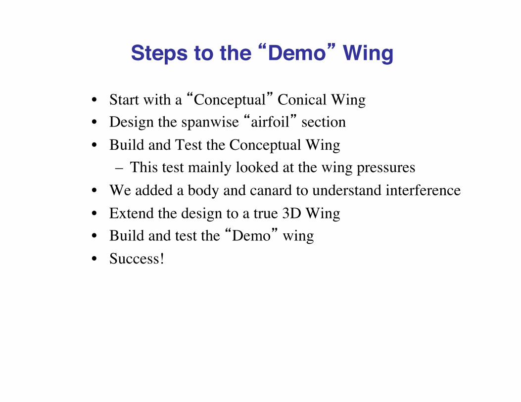
Steps to the “Demo” Wing
• Start with a “Conceptual” Conical Wing• Design the spanwise “airfoil” section• Build and Test the Conceptual Wing
– This test mainly looked at the wing pressures• We added a body and canard to understand interference• Extend the design to a true 3D Wing• Build and test the “Demo” wing• Success!

Computational Design Spanwise PressuresFinal DesignInitial Camber Studies
AIAA-1980-1421 “Controlled Supercritical Crossflow on Supersonic Wings”

A WT Model to see if the CFD is valid
AIAA-1980-1421 “Controlled Supercritical Crossflow on Supersonic Wings”
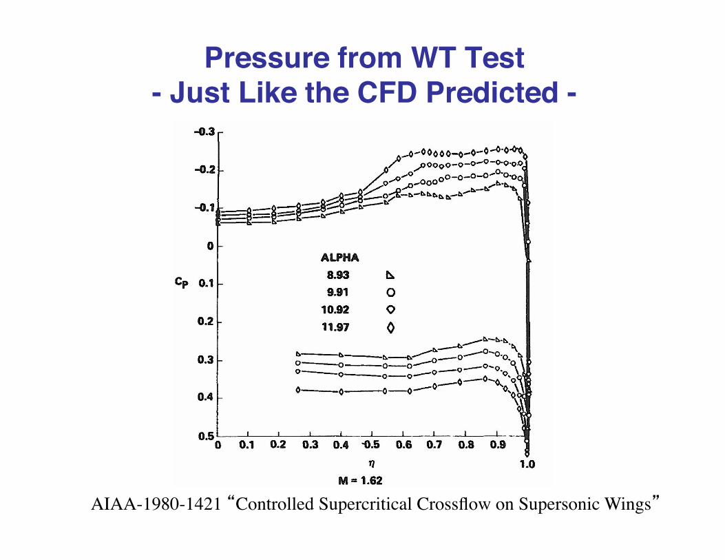
Pressure from WT Test- Just Like the CFD Predicted -
AIAA-1980-1421 “Controlled Supercritical Crossflow on Supersonic Wings”
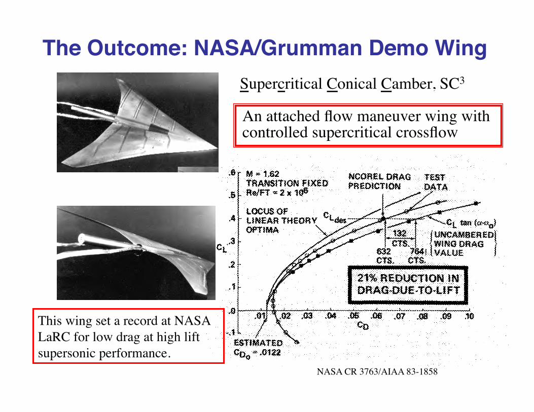
The Outcome: NASA/Grumman Demo Wing
NASA CR 3763/AIAA 83-1858
Supercritical Conical Camber, SC3
An attached flow maneuver wing with controlled supercritical crossflow
This wing set a record at NASA LaRC for low drag at high lift supersonic performance.
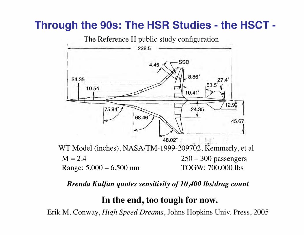
Through the 90s: The HSR Studies - the HSCT -The Reference H public study configuration
WT Model (inches), NASA/TM-1999-209702, Kemmerly, et al
In the end, too tough for now.
M = 2.4 250 – 300 passengersRange: 5,000 – 6,500 nm TOGW: 700,000 lbs
Erik M. Conway, High Speed Dreams, Johns Hopkins Univ. Press, 2005
Brenda Kulfan quotes sensitivity of 10,400 lbs/drag count

In the 90s At Virginia Tech: HSCT MDO
Knill, D.L., Giunta, A.A., Baker, C.A., Grossman, B., Mason, W.H., Haftka, R.T. and Watson, L.T., “Response Surface Models Combining Linear and Euler Aerodynamics for Supersonic Transport Design,” Journal of Aircraft, Vol. 36, No. 1, Jan-Feb 1999, pp. 75-86.

Lucky Break in Grid Generation

The key to the next step: sonic boom -can we reduce the strength?
• Typical boom overpressure: 1.5 psf• Would 0.3 psf be OK?• Need new FAA rule
An F-5E modified to demonstrate “shaping” of the sonic boom signature, success achieved in 2003
The heritage here is the DARPA Quiet Supersonic Platform (QSP) program, that kicked off in late 2000

Conventional N-wave, and future target for the “sonic boom”
-1.5
-1.0
-0.5
0.0
0.5
1.0
1.5
-20 0 20 40 60 80 100 120 140 160 180 200
Time (milliseconds)
Pre
ssur
e C
hang
e (p
sf)
Conventional N-Wave Boom Signature
RampFlat
Initial Overpressure0.4 pounds/foot2
Target
From “Conceptual Design of a Sonic Boom Constrained Supersonic Business Aircraft” by David C. Aronstein and Kurt L. Schueler, AIAA Paper 2004-0697

Keys to Reducing Boom Strength
• Extending the configuration length• Low Aircraft weight• Careful shaping of volume and lift
distribution
X-54 X-plane designation obtained by Gulfstream for a low boom strength demonstrator

One way to increase length: The Quiet Spike“Spike” extends in flight, see AIAA Paper 2008-123, Jan. 2008 for overview

The hope is for Supersonic Biz Jets
One concept from Aerion, depends also on obtaining laminar flow
Now teamed with Airbus and a 3-engine design!
From the Aerion web site: http://www.aerioncorp.com/

What’s the Aerion Idea?This is a case where 2D supersonic airfoil theory is interesting
-0.06
-0.04
-0.02
0.00
0.02
0.04
0.06
0.0 0.20 0.40 0.60 0.80 1.0
y/c
x/c
5% thick biconvex airfoil
-0.30
-0.20
-0.10
0.00
0.10
0.20
0.300.0 0.20 0.40 0.60 0.80 1.0
Cp
x/c
Upper Surface
Lower Surface
M = 2, 5° angle of atteck
2D supersonic thin airfoil theory
2D supersonic airfoil pressures look nothing like the subsonic pressures
A favorable pressure gradient all the way to the trailing edge means that you might be able to get laminar flow!
- Small chord - High altitudes
Implies a relatively low Re
Also observe that the upper and lower surface pressures don’t have to be equal at the TE when it’s a supersonic TE edge

Today’s Aerion Concept
Revised Design, with Airbus – Nov., 2013?
http://www.aerionsupersonic.com/as2.aspx

A Breakthrough?
AIAA Daily Launch, April 3, 2012NASA Claims Supersonic Aircraft Breakthrough.
Aviation Daily (4/2, Warwick) reported, “NASA is claiming a breakthrough in the design of supersonic aircraft, with wind-tunnel tests proving it is possible to design configurations that combine low sonic boom with low cruise drag, characteristics once thought to be mutually exclusive.” Testing of scale models designed by Boeing and Lockheed Martin that could be available by 2025 showed that “design tools could produce a supersonic business jet capable of unrestricted overland flight,” says Peter Coen, NASA’s Supersonic Fixed-Wing project manager. Coen added, “It’s the first time we have taken a design representative of a small supersonic airliner and shown we can change the configuration in a way that is compatible with high efficiency and have a sonic signature than is not a boom.” Both companies are now trying to “refine” the designs.
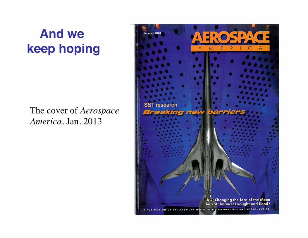
And we keep hoping
The cover of Aerospace America, Jan. 2013

Current Programs – Spring 2016• NASA Low Boom Supersonic Demonstrator - QueSST Program, 20M to Lockheed Martin
Boom Technology
Spike Aerospace
In the next few years we’ll see how these programs turn out.

To conclude• Today “we” can supercruise with the F-22• There is a possibility of lowering the sonic
boom overpressure, and a new FAA rule allowing supersonic flight over land.
• We may see supersonic business jets in the “not too distant” future, especially if the FAA allows supersonic flight over land.
I have Brenda Kulfan’s Supersonic Aerodynamics Lecture Series, given at UVA in November 2008, for any student that wants it.
Related Documents