IOSR Journal of Mechanical and Civil Engineering (IOSR-JMCE) e-ISSN: 2278-1684,p-ISSN: 2320-334X, Volume 7, Issue 3 (Jul. - Aug. 2013), PP 15-24 www.iosrjournals.org www.iosrjournals.org 15 | Page Some Studies on Mode-II Fracture of Light Weight Blended Aggregate Concrete Dr. V. Bhaskar Desai 1 , K. Mallikarjunappa 2, A. Sathyam 3 , B. Vijaya Tejaswini 4 1 Professor, Dept. of Civil Engineering, JNTUA College of Engineering, Anantapuram – 515002, A.P. 2 Dy. Executive Engineer, Dharmavaram Municipality, Dharmavaram – 515671, & Research Scholar, JNTUA College of Engineering, Anantapuram – 515002, A.P. 3 Conservation Assistant Gr-I, Archaeological Survey of India, Anantapuram Sub Circle, Anantapur & Research Scholar, JNTUA College of Engineering, Anantapuram – 515002, A.P. 4 M.Tech. Student, JNTUA College of Engineering, Anantapuram – 515002, A.P. Abstract: Blended aggregate in concrete and arriving at the structural properties of blended aggregate concrete is a thrust area. Pumice is very light and porous igneous rock that is formed during volcanic eruptions.Cinder is a waste material obtained from steel manufacturing units. Shear strength is a property of major significance for wide range of civil engineering materials and structures. Shear and punching shear failures particularly in deep beams, in corbels and in concrete flat slabs are considered to be more critical and catastrophic than other types of failures. This area has received greater attention in recent years. For investigating shear type of failures, from the literature it is found that double central notched (DCN) specimen geometry proposed by Prakash Desai and V.Bhaskar Desai is supposed the best suited geometry. In this present experimental investigation an attempt is made to study the Mode-II fracture property of light weight blended aggregate cement concrete combining both the pumice and cinder in different proportions, and making use of DCN test specimen geometry . By blending the pumice and cinder in different percentages of 0, 25, 50, 75 and 100 by volumeof concrete, a blended light weight aggregate concrete is prepared. By using this the property such as in plane shear strength is studied. Finally an analysis is carried out regarding Mode-II fracture properties of blended concrete. It is concluded that the Ultimate load in Mode-II is found to decrease continuously with the percentage increase in Pumice aggregate content. It is also observed that the ultimate stress in Mode II is found to increase continuously with percentage increase in cinder aggregate content. Key Words: Cinder, light weight aggregate, Mode II fracture, shear strength, Pumice. I. Introduction: The advancement in the new construction materials has lead to develop high strength materials, which are generally selected to reduce the weight of the construction. Also the developments in the stress analysis methods enable a more reliable determination of local stresses in the materials, which permit safety factors to be reduced resulting in further weight savings. This induces low margins of safety for the structures designed with high strength materials. But the service stresses with aggressive environment may be high enough to induce cracks, particularly if pre existing flaws or high stress concentrations are present with in the materials. As the residual strength of any structural material under the presence of cracks is low, when small cracks exists, the structures designed with high strength materials may fail at stresses below the highest service stresses for which they are designed. If a structural element is considered in which crack has developed due to bad workmanship, due to the application of repeated loads or combination of loads and aggressive environmental conditions this crack will grow with time (Fig .1). The longer the crack, the higher the stress concentration induced by it. This indicates that the rate of crack propagation will increase with time.The total useful life of the structural component depends on the time necessary to initiate a crack and to propagate the crack from subcritical dimensions to the critical size due to cyclic stresses.Due to the presence of the crack the strength of the structure will decrease, which will be lower than the original design strength. The variation of residual strength of a structural element with variations in crack size and time is shown in Fig .2. Submitted date 08 June 2013 Accepted Date: 15 June 2013

Welcome message from author
This document is posted to help you gain knowledge. Please leave a comment to let me know what you think about it! Share it to your friends and learn new things together.
Transcript
IOSR Journal of Mechanical and Civil Engineering (IOSR-JMCE)
e-ISSN: 2278-1684,p-ISSN: 2320-334X, Volume 7, Issue 3 (Jul. - Aug. 2013), PP 15-24 www.iosrjournals.org
www.iosrjournals.org 15 | Page
Some Studies on Mode-II Fracture of Light Weight Blended
Aggregate Concrete
Dr. V. Bhaskar Desai 1, K. Mallikarjunappa
2, A. Sathyam
3,
B. Vijaya Tejaswini 4
1 Professor, Dept. of Civil Engineering, JNTUA College of Engineering, Anantapuram – 515002, A.P. 2 Dy. Executive Engineer, Dharmavaram Municipality, Dharmavaram – 515671, & Research Scholar, JNTUA
College of Engineering, Anantapuram – 515002, A.P. 3 Conservation Assistant Gr-I, Archaeological Survey of India, Anantapuram Sub Circle, Anantapur & Research
Scholar, JNTUA College of Engineering, Anantapuram – 515002, A.P. 4 M.Tech. Student, JNTUA College of Engineering, Anantapuram – 515002, A.P.
Abstract: Blended aggregate in concrete and arriving at the structural properties of blended aggregate
concrete is a thrust area. Pumice is very light and porous igneous rock that is formed during volcanic
eruptions.Cinder is a waste material obtained from steel manufacturing units. Shear strength is a property of
major significance for wide range of civil engineering materials and structures. Shear and punching shear
failures particularly in deep beams, in corbels and in concrete flat slabs are considered to be more critical and
catastrophic than other types of failures. This area has received greater attention in recent years. For
investigating shear type of failures, from the literature it is found that double central notched (DCN) specimen
geometry proposed by Prakash Desai and V.Bhaskar Desai is supposed the best suited geometry. In this present experimental investigation an attempt is made to study the Mode-II fracture property of light weight blended
aggregate cement concrete combining both the pumice and cinder in different proportions, and making use of
DCN test specimen geometry . By blending the pumice and cinder in different percentages of 0, 25, 50, 75 and
100 by volumeof concrete, a blended light weight aggregate concrete is prepared. By using this the property
such as in plane shear strength is studied. Finally an analysis is carried out regarding Mode-II fracture
properties of blended concrete. It is concluded that the Ultimate load in Mode-II is found to decrease
continuously with the percentage increase in Pumice aggregate content. It is also observed that the ultimate
stress in Mode II is found to increase continuously with percentage increase in cinder aggregate content.
Key Words: Cinder, light weight aggregate, Mode II fracture, shear strength, Pumice.
I. Introduction: The advancement in the new construction materials has lead to develop high strength materials, which
are generally selected to reduce the weight of the construction. Also the developments in the stress analysis methods enable a more reliable determination of local stresses in the materials, which permit safety factors to be
reduced resulting in further weight savings. This induces low margins of safety for the structures designed with
high strength materials. But the service stresses with aggressive environment may be high enough to induce
cracks, particularly if pre existing flaws or high stress concentrations are present with in the materials. As the
residual strength of any structural material under the presence of cracks is low, when small cracks exists, the
structures designed with high strength materials may fail at stresses below the highest service stresses for which
they are designed.
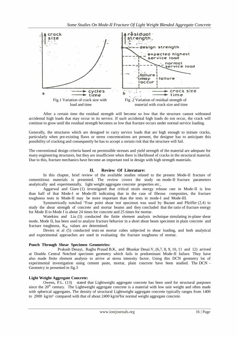
If a structural element is considered in which crack has developed due to bad workmanship, due to the
application of repeated loads or combination of loads and aggressive environmental conditions this crack will
grow with time (Fig .1). The longer the crack, the higher the stress concentration induced by it. This indicates
that the rate of crack propagation will increase with time.The total useful life of the structural component depends on the time necessary to initiate a crack and to propagate the crack from subcritical dimensions to the
critical size due to cyclic stresses.Due to the presence of the crack the strength of the structure will decrease,
which will be lower than the original design strength. The variation of residual strength of a structural element
with variations in crack size and time is shown in Fig .2.
Submitted date 08 June 2013 Accepted Date: 15 June 2013
Some Studies On Mode-II Fracture Of Light Weight Blended Aggregate Concrete
www.iosrjournals.org 16 | Page
Fig.1 Variation of crack size with Fig .2 Variation of residual strength of
load and time material with crack size and time
After a certain time the residual strength will become so low that the structure cannot withstand
accidental high loads that may occur in its service. If such accidental high loads do not occur, the crack will
continue to grow until the residual strength becomes so low that fracture occurs under normal service loading.
Generally, the structures which are designed to carry service loads that are high enough to initiate cracks, particularly when pre-existing flaws or stress concentrations are present, the designer has to anticipate this
possibility of cracking and consequently he has to accept a certain risk that the structure will fail.
The conventional design criteria based on permissible stresses and yield strength of the material are adequate for
many engineering structures, but they are insufficient when there is likelihood of cracks in the structural material.
Due to this, fracture mechanics have become an important tool in design with high strength materials.
II. Review Of Literature:
In this chapter, brief review of the available studies related to the present Mode-II fracture of
cementitious materials is presented. The review covers the study on mode-II fracture parameters
analytically and experimentally, light weight aggregate concrete properties etc.,
Aggarwal and Giare (1) investigated that critical strain energy release rate in Mode-II is less
than half of that Mode-I or Mode-III indicating that in the case of fibrous composites, the fracture
toughness tests in Mode-II may be more important than the tests in mode-I and Mode-III.
Symmetrically notched “Four point shear test specimen was used by Bazant and Pfeiffer (2,4) to
study the shear strength of concrete and mortar beams and they concluded that the ratio of fracture energy for Mode II to Mode I is about 24 times for concrete and 25 times for mortar.
Watekins and Liu (3) conducted the finite element analysis technique simulating in-plane shear
mode, Mode II, has been used to analyze fracture behavior in a short shear beam specimen in plain concrete and
fracture toughness, KIIc values are determined.
Devies et al (5) conducted tests on mortar cubes subjected to shear loading, and both analytical
and experimental approaches are used in evaluating the fracture toughness of mortar.
Punch Through Shear Specimen Geometries:
Prakash Desayi, Raghu Prasad B.K, and Bhaskar Desai.V, (6,7, 8, 9, 10, 11 and 12) arrived at Double Central Notched specimen geometry which fails in predominant Mode-II failure. They have
also made finite element analysis to arrive at stress intensity factor. Using this DCN geometry lot of
experimental investigation using cement paste, mortar, plain concrete have been studied. The DCN –
Geometry in presented in fig.3
Light Weight Aggregate Concrete:
Owens, P.L. (13) stated that Lightweight aggregate concrete has been used for structural purposes since the 20th century. The Lightweight aggregate concrete is a material with low unit weight and often made
with spherical aggregates. The density of structural Lightweight aggregate concrete typically ranges from 1400
to 2000 kg/m³ compared with that of about 2400 kg/m³for normal weight aggregate concrete.
Some Studies On Mode-II Fracture Of Light Weight Blended Aggregate Concrete
www.iosrjournals.org 17 | Page
Blended Aggregate:
These Tertiary and Quaternary volcanic are low-density glass and vesicular material including, but not
limited to, pumice and volcanic cinder. The distribution is widespread throughout the West with the principal producers being New Mexico, California, Oregon, Idaho and Arizona. The primary user is the construction
industry where weight reduction equates to cost savings. Principal products in which natural lightweight
aggregate is utilized because of its lower density include lightweight Portland cement concrete and lightweight
concrete masonry units. In addition, due to location, some natural lightweights compete with normal weight
constructions aggregates for uses such as road base and common backfill material.
Yang and Huang (14), stated that naturally available LWA such as volcanic cinder, pumice and scoria
possess very strength due to the higher porosity.
L. Calaveri et. al (15) discussed the properties of lightweight pumice stone concrete (LWPSC)
and suggested that pumice can really be considered an alternative to common artificial light weight
aggregate, taking into account the performance pointed out by loading tests carried out on structural
systems made of LWPSC. Dr.V.Bhaskar Desai, Dr.B.L.P.Swamy, N.ShivalingaRao (16) it is observed that with the 30%
replacement of conventional granite by light weight aggregate and with 15% replacement of cement by double
blended pozzolonic material (metakoline + pumice powder and silica fume + flyash) the strengths were found to
be optimum. In terms of economy considerations a brief report on cost analysis was prepared. From the cost
analysis it was observed that there can be savings up to Rs. 800 per cubic meter of concrete.
Expermental Investigation:
An experimental study has been conducted on concrete with partial replacement of light weight
coarse aggregate i.e., Cinder by another light weight aggregate i.e., Pumice in Mode-II fracture with few
different volumetric fractional additions ranging from 0% to 100%. Concrete of M20 design mix is used
in the present investigation. The test programme consists of carrying out shear strength tests on notched
specimens having different a/w ratios. Analysis of the results has been done to investigate the shear
strength variation in Mode-II fracture with addition of different % of Pumice. Variations of various
combinations have been studied.
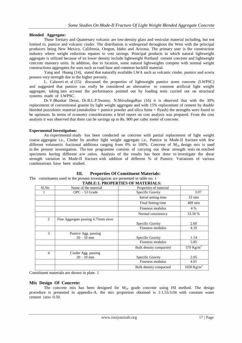
III. Properties Of Constituent Materials: The constituents used in the present investigation are presented in table no. 1
TABLE:1. PROPERTIES OF MATERIALS: Sl.No Name of the material Properties of material
1 OPC – 53 Grade Specific Gravity 3.07
Initial setting time 33 min
Final Setting time 489 min
Fineness modulus 4 %
Normal consistency 33.50 %
2 Fine Aggregate passing 4.75mm sieve
Specific Gravity
2.60
Fineness modulus 4.10
3 Pumice Agg. passing 20 – 10 mm
Specific Gravity
1.14
Fineness modulus 5.85
Bulk density compacted 570 Kg/m3
4 Cinder Agg. passing 20 – 10 mm
Specific Gravity
2.05
Fineness modulus 4.01
Bulk density compacted 1050 Kg/m3
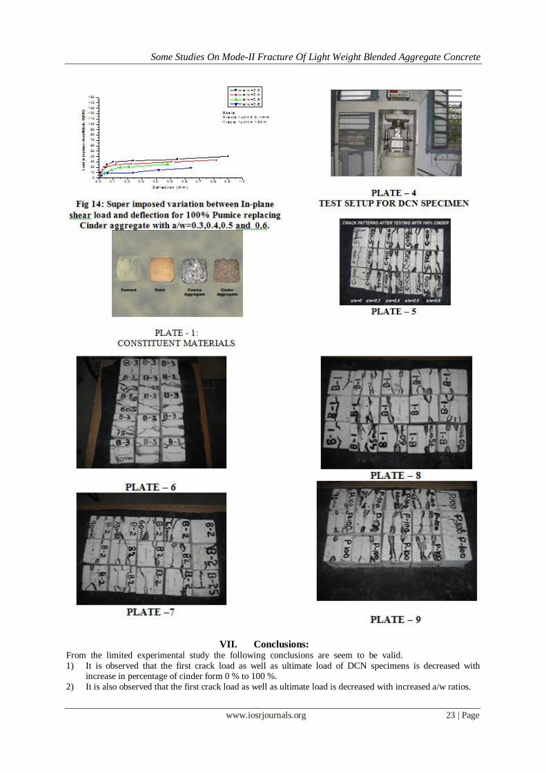
Constituent materials are shown in plate. 1
Mix Design Of Concrete: The concrete mix has been designed for M20 grade concrete using ISI method. The design
procedure is presented in appendix-A. the mix proportion obtained is 1:1.55:3.04 with constant water
cement ratio 0.50.
Some Studies On Mode-II Fracture Of Light Weight Blended Aggregate Concrete
www.iosrjournals.org 18 | Page
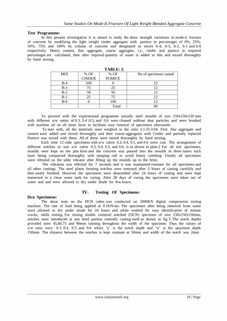
Test Programme: In this present investigation it is aimed to study the shear strength variations in mode-ii fracture
of concrete by modifying the light weight cinder aggregate with pumice in percentages of 0%, 25%,
50%, 75% and 100% by volume of concrete and designated as mixes b-4, b-3, b-2, b-1 and b-0
respectively. Hence cement, fine aggregate, coarse aggregate, i.e., cinder and pumice in required
percentages are calculated, then after required quantity of water is added to this and mixed thoroughly
by hand mixing.
TABLE: 2.
MIX % OF
CINDER
% OF
PUMICE
No of specimens casted
B-4 100 0 12
B-3 75 25 12
B-2 50 50 12
B-1 25 75 12
B-0 0 100 12
Total 60
To proceed with the experimental programme initially steel moulds of size 150x150x150 mm
with different a/w ratios of 0.3, 0.4 ,0.5, and 0.6 were cleaned without dust particles and were brushed
with machine oil on all inner faces to facilitate easy removal of specimens afterwards.
To start with, all the materials were weighed in the ratio 1:1.55:3.04. First fine aggregate and
cement were added and mixed thoroughly and then coarse aggregates with Cinder and partially replaced Pumice was mixed with them. All of these were mixed thoroughly by hand mixing.
Each time 12 cube specimens with a/w ratios 0.3, 0.4, 0.5, and 0.6 were cast. The arrangement of
different notches to suit a/w ratios 0.3, 0.4, 0.5, and 0.6. is as shown in plate.2 For all test specimens,
moulds were kept on the plat form and the concrete was poured into the moulds in three layers each
layer being compacted thoroughly with tamping rod to avoid honey combing. Finally all specimens
were vibrated on the table vibrator after filling up the moulds up to the brim.
The vibration was effected for 7 seconds and it was maintained constant for all specimens and
all other castings. The steel plates forming notches were removed after 3 hours of casting carefully and
then neatly finished. However the specimens were demoulded after 24 hours of casting and were kept
immersed in a clean water tank for curing. After 28 days of curing the specimens were taken out of
water and and were allowed to dry under shade for few hours.
IV. Testing Of Specimens: Dcn Specimens:
The shear tests on the DCN cubes was conducted on 2000KN digital compression testing
machine. The rate of load being applied at 0.1KN/sec. The specimens after being removed from water
were allowed to dry under shade for 24 hours and white washed for easy identification of minute
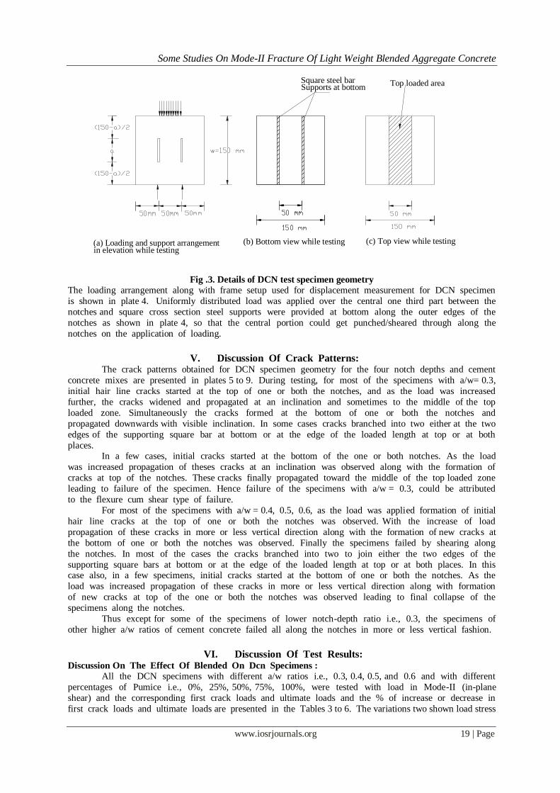
cracks, while testing. For testing double centered notched (DCN) specimen of size 150x150x150mm,
notches were introduced at one third portion centrally casting itself as shown in fig 3. The notch depths
provided were 45,60,75 and 90mm running throughout the width of the specimen. Thus the values of
a/w ratio were 0.3, 0.4, 0.5, and 0.6 where „a‟ is the notch depth and „w‟ is the specimen depth
150mm. The distance between the notches is kept constant at 50mm and width of the notch was 2mm.
Some Studies On Mode-II Fracture Of Light Weight Blended Aggregate Concrete
www.iosrjournals.org 19 | Page
Fig .3. Details of DCN test specimen geometry
The loading arrangement along with frame setup used for displacement measurement for DCN specimen
is shown in plate 4. Uniformly distributed load was applied over the central one third part between the
notches and square cross section steel supports were provided at bottom along the outer edges of the
notches as shown in plate 4, so that the central portion could get punched/sheared through along the
notches on the application of loading.
V. Discussion Of Crack Patterns:
The crack patterns obtained for DCN specimen geometry for the four notch depths and cement
concrete mixes are presented in plates 5 to 9. During testing, for most of the specimens with a/w= 0.3,
initial hair line cracks started at the top of one or both the notches, and as the load was increased
further, the cracks widened and propagated at an inclination and sometimes to the middle of the top
loaded zone. Simultaneously the cracks formed at the bottom of one or both the notches and
propagated downwards with visible inclination. In some cases cracks branched into two either at the two
edges of the supporting square bar at bottom or at the edge of the loaded length at top or at both
places. In a few cases, initial cracks started at the bottom of the one or both notches. As the load
was increased propagation of theses cracks at an inclination was observed along with the formation of
cracks at top of the notches. These cracks finally propagated toward the middle of the top loaded zone
leading to failure of the specimen. Hence failure of the specimens with a/w = 0.3, could be attributed
to the flexure cum shear type of failure.
For most of the specimens with a/w = 0.4, 0.5, 0.6, as the load was applied formation of initial
hair line cracks at the top of one or both the notches was observed. With the increase of load
propagation of these cracks in more or less vertical direction along with the formation of new cracks at
the bottom of one or both the notches was observed. Finally the specimens failed by shearing along
the notches. In most of the cases the cracks branched into two to join either the two edges of the
supporting square bars at bottom or at the edge of the loaded length at top or at both places. In this case also, in a few specimens, initial cracks started at the bottom of one or both the notches. As the
load was increased propagation of these cracks in more or less vertical direction along with formation
of new cracks at top of the one or both the notches was observed leading to final collapse of the
specimens along the notches.
Thus except for some of the specimens of lower notch-depth ratio i.e., 0.3, the specimens of
other higher a/w ratios of cement concrete failed all along the notches in more or less vertical fashion.
VI. Discussion Of Test Results:
Discussion On The Effect Of Blended On Dcn Specimens :
All the DCN specimens with different a/w ratios i.e., 0.3, 0.4, 0.5, and 0.6 and with different
percentages of Pumice i.e., 0%, 25%, 50%, 75%, 100%, were tested with load in Mode-II (in-plane
shear) and the corresponding first crack loads and ultimate loads and the % of increase or decrease in
first crack loads and ultimate loads are presented in the Tables 3 to 6. The variations two shown load stress
(a) Loading and support arrangement in elevation while testing
(b) Bottom view while testing (c) Top view while testing
Square steel bar Supports at bottom Top loaded area
Some Studies On Mode-II Fracture Of Light Weight Blended Aggregate Concrete
www.iosrjournals.org 20 | Page
permeations versus percentage of pumice replacing the cinder are presented in fig 4 to 9 for various a/w ratios
and different percentage of pumice & cinder These graphs show the variation of first crack load in shear
verses percentage of Pumice for different a/w ratios. Variation of load in Mode-II (In-plane shear) verses displacement (P-δ diagrams) are shown in graphs for a/w ratios 0.3, 0.4, 0.5, 0.6 with different
% Pumice i.e., 0%, 25%, 50%, 75%, 100%. The figures for different a/w ratios are shown in figs 5-14.
Influence Of Cinder On In-Plane Shear Strength: All the DCN specimens with different a/w ratios i.e., 0.3, 0.4, 0.5, and 0.6 and with different
percentages of pumice replacing with cinder i.e., 0%, 25%, 50%, 75%, 100%, were tested with load in Mode-II (in-plane shear).
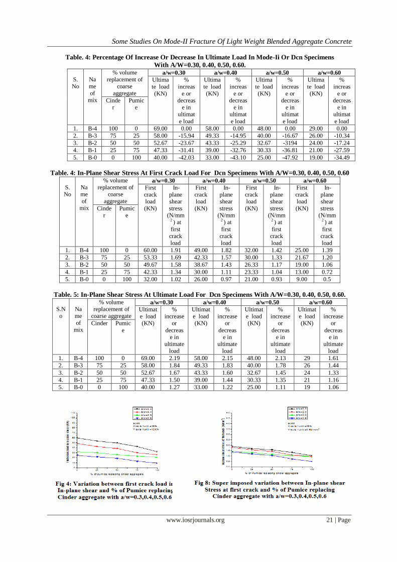
a) The variations of first crack loads and the % of increase or decrease in first crack loads versus
percentage of pumice are presented in the figs .4 and 5. These are presented for different a/w ratios
(i.e., 0.3, 0.4, 0.5, 0.6). from these diagrams it is observed that with the increase in percentage of
pumice and a/w ratio first crack load decreases.
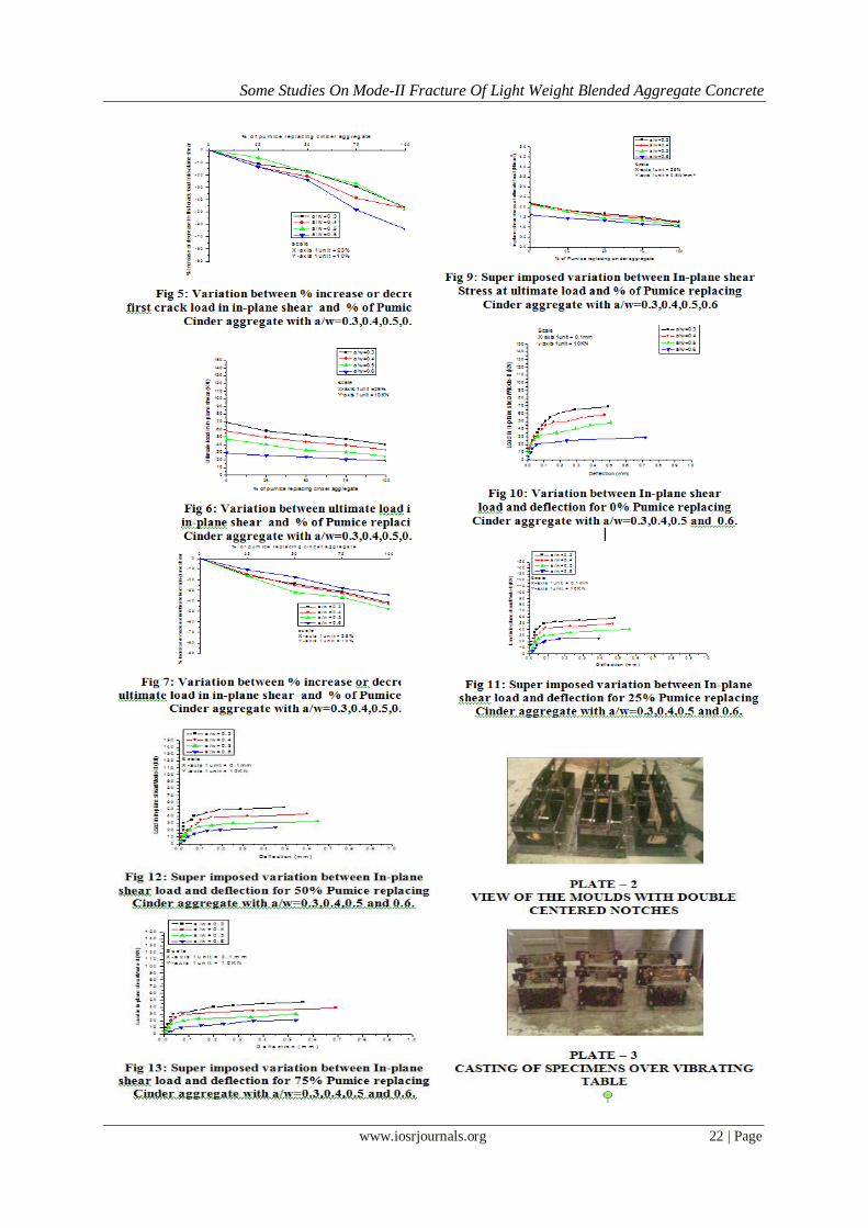
b) The variations of ultimate loads and the % of increase or decrease in ultimate loads versus
percentage of cinder are presented in the figs .6 and 7. These are presented for different a/w ratios
(i.e., 0.3, 0.4, 0.5, 0.6). From these diagrams it is observed that with the increase in percentage of
pumice and a/w ratio ultimate load decreases and also percentage decrease in ultimate load is
increasing.
c) Super-imposed variations of first crack shear stress, percentage increase or decrease in first crack
strength in in-plane shear Versus percentage of pumice for different a/w ratios (i.e., 0.3,0.4,0.5,0.6) is presented in fig .8. It is observed that the percentage of pumice increase in first crack load in in-plane
shear is increased.
d) Super-imposed variations of ultimate shear stress, percentage increase or decrease in ultimate stress in
in-plane shear Versus percentage of pumice for different a/wratios (i.e., 0.3,0.4,0.5,0.6) is presented in
figs .9. It is observed that the in plane shear stress at ultimate load is decreased with increasing percentage of
pumice.
e) From the super-imposed variations between in-plane shear load versus deflections for different
percentage replacement of pumice (i.e., 0%, 25%, 50% and 100% ) are presented in fig 10 to 14. It is
observed that the deflection is increased with increasing in plane shear load.
f) The In-plane shear stress at first crack and at ultimate load for different percentages of pumice
aggregate (0-100%) and for different notch depth ratios are presented in table. 5, table. 6.
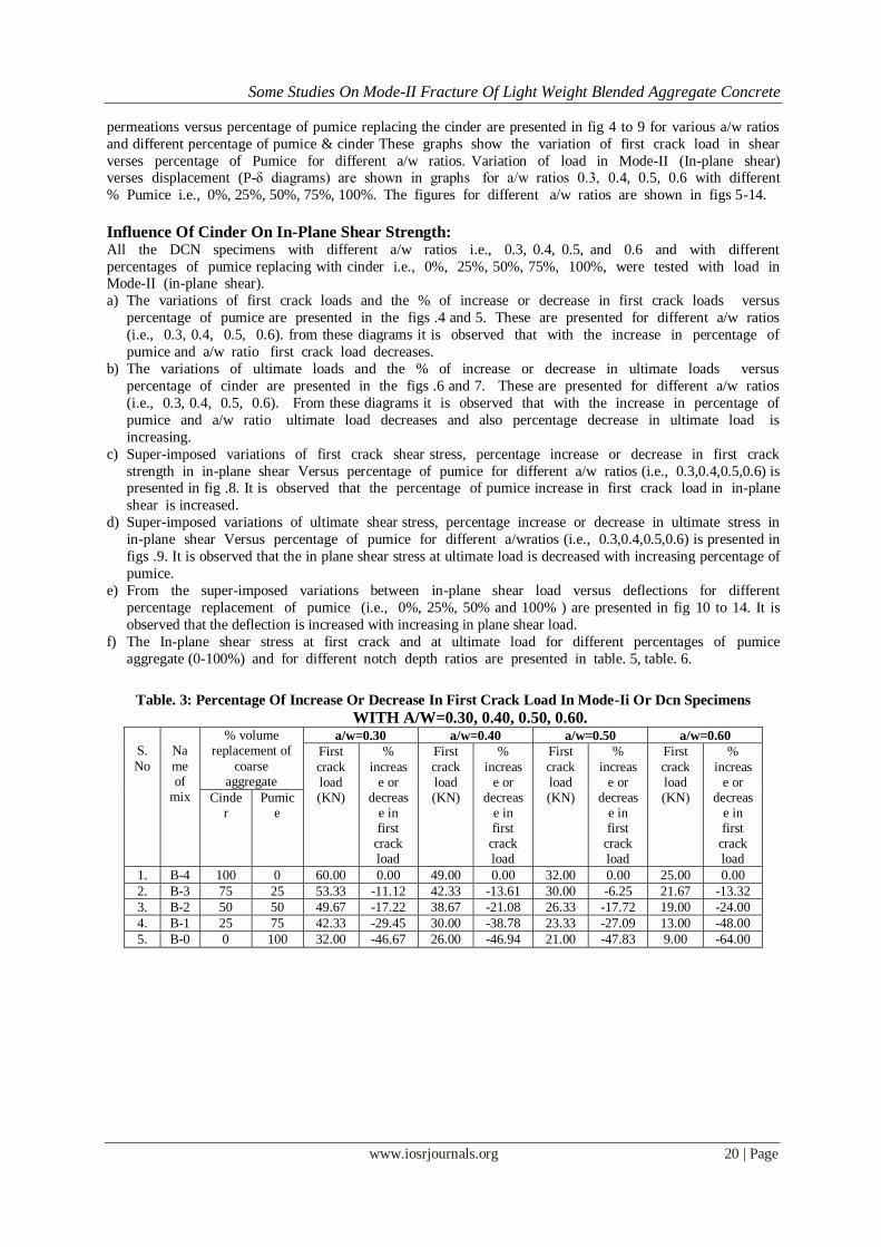
Table. 3: Percentage Of Increase Or Decrease In First Crack Load In Mode-Ii Or Dcn Specimens
WITH A/W=0.30, 0.40, 0.50, 0.60.
S.
No
Na
me of
mix
% volume replacement of
coarse aggregate
a/w=0.30 a/w=0.40 a/w=0.50 a/w=0.60
First
crack load (KN)
%
increase or
decrease in first
crack load
First
crack load (KN)
%
increase or
decrease in first
crack load
First
crack load (KN)
%
increase or
decrease in first
crack load
First
crack load (KN)
%
increase or
decrease in first
crack load
Cinder
Pumice
1. B-4 100 0 60.00 0.00 49.00 0.00 32.00 0.00 25.00 0.00
2. B-3 75 25 53.33 -11.12 42.33 -13.61 30.00 -6.25 21.67 -13.32
3. B-2 50 50 49.67 -17.22 38.67 -21.08 26.33 -17.72 19.00 -24.00
4. B-1 25 75 42.33 -29.45 30.00 -38.78 23.33 -27.09 13.00 -48.00
5. B-0 0 100 32.00 -46.67 26.00 -46.94 21.00 -47.83 9.00 -64.00
Some Studies On Mode-II Fracture Of Light Weight Blended Aggregate Concrete
www.iosrjournals.org 21 | Page
Table. 4: Percentage Of Increase Or Decrease In Ultimate Load In Mode-Ii Or Dcn Specimens
With A/W=0.30, 0.40, 0.50, 0.60.
S.No
Name of
mix
% volume replacement of
coarse aggregate
a/w=0.30 a/w=0.40 a/w=0.50 a/w=0.60
Ultimate load (KN)
% increas
e or decreas
e in ultimat
e load
Ultimate load (KN)
% increas
e or decreas
e in ultimat
e load
Ultimate load (KN)
% increas
e or decreas
e in ultimat
e load
Ultimate load (KN)
% increas
e or decreas
e in ultimat
e load
Cinder
Pumice
1. B-4 100 0 69.00 0.00 58.00 0.00 48.00 0.00 29.00 0.00
2. B-3 75 25 58.00 -15.94 49.33 -14.95 40.00 -16.67 26.00 -10.34
3. B-2 50 50 52.67 -23.67 43.33 -25.29 32.67 -3194 24.00 -17.24
4. B-1 25 75 47.33 -31.41 39.00 -32.76 30.33 -36.81 21.00 -27.59
5. B-0 0 100 40.00 -42.03 33.00 -43.10 25.00 -47.92 19.00 -34.49
Table. 4: In-Plane Shear Stress At First Crack Load For Dcn Specimens With A/W=0.30, 0.40, 0.50, 0.60
S.No
Name of
mix
% volume replacement of
coarse aggregate
a/w=0.30 a/w=0.40 a/w=0.50 a/w=0.60
First crack load (KN)
In-plane shear stress
(N/mm2 ) at
first crack load
First crack load (KN)
In-plane shear stress
(N/mm2 ) at
first crack load
First crack load (KN)
In-plane shear stress
(N/mm2 ) at
first crack load
First crack load (KN)
In-plane shear stress
(N/mm2 ) at
first crack load
Cinder
Pumice
1. B-4 100 0 60.00 1.91 49.00 1.82 32.00 1.42 25.00 1.39
2. B-3 75 25 53.33 1.69 42.33 1.57 30.00 1.33 21.67 1.20
3. B-2 50 50 49.67 1.58 38.67 1.43 26.33 1.17 19.00 1.06
4. B-1 25 75 42.33 1.34 30.00 1.11 23.33 1.04 13.00 0.72
5. B-0 0 100 32.00 1.02 26.00 0.97 21.00 0.93 9.00 0.5
Table. 5: In-Plane Shear Stress At Ultimate Load For Dcn Specimens With A/W=0.30, 0.40, 0.50, 0.60.
S.No
Name of
mix
% volume replacement of
coarse aggregate
a/w=0.30 a/w=0.40 a/w=0.50 a/w=0.60
Ultimate load (KN)
% increase
or
decrease in
ultimate load
Ultimate load (KN)
% increase
or
decrease in
ultimate load
Ultimate load (KN)
% increase
or
decrease in
ultimate load
Ultimate load (KN)
% increase
or
decrease in
ultimate load
Cinder Pumic
e
1. B-4 100 0 69.00 2.19 58.00 2.15 48.00 2.13 29 1.61
2. B-3 75 25 58.00 1.84 49.33 1.83 40.00 1.78 26 1.44
3. B-2 50 50 52.67 1.67 43.33 1.60 32.67 1.45 24 1.33
4. B-1 25 75 47.33 1.50 39.00 1.44 30.33 1.35 21 1.16
5. B-0 0 100 40.00 1.27 33.00 1.22 25.00 1.11 19 1.06
Some Studies On Mode-II Fracture Of Light Weight Blended Aggregate Concrete
www.iosrjournals.org 22 | Page
Some Studies On Mode-II Fracture Of Light Weight Blended Aggregate Concrete
www.iosrjournals.org 23 | Page
VII. Conclusions: From the limited experimental study the following conclusions are seem to be valid.
1) It is observed that the first crack load as well as ultimate load of DCN specimens is decreased with increase in percentage of cinder form 0 % to 100 %.
2) It is also observed that the first crack load as well as ultimate load is decreased with increased a/w ratios.
Some Studies On Mode-II Fracture Of Light Weight Blended Aggregate Concrete
www.iosrjournals.org 24 | Page
3) It is observed that in plane shear stress at first crack load as well as at ultimate load is increased with
increasing percentage of cinder.
4) It is also observed that the in plane shear at first crack load as well as at ultimate load is decreased with increased a/w ratios.
References:
[1]. Agarwal, B.D. and Giare, G.S., “Fracture toughness of short-fiber composites in Modes-I and II”, Engineering Fracture
Mechanics, Vol. 15, No. 1, 1981, pp.219-230.
[2]. Bazant , Z.,p, and Pfeiffer, P.A., “Shear fracture tests of concrete”, materials and structures (RKLEM) , 1984, vol. 19,
pp.111-121.
[3]. Watkins, J. and Liu, K.L.W., “A Finite Element Study of Short Beam Test Specimens under Mode -II loading”, The
International Journal of Cement Composites and Light Weight Concrete, Vol.7, No.1, Feb.1985, pp.39-47.
[4]. Bazant , Z.,p, and Pfeiffer, P.A., “Tests on shear fracture and strain softening in concrete”, proceedings of second
symposium on interaction of Non-nuclear Munition with structures Florida, USA, April 1985, pp. 254-264.
[5]. Davies, J., Yim, C.W.A and Morgan, T.G., “Determination of Fracture parameters of punch through shear specimens” , The
International Journal of Cement Composites and Light weight Concrete, Vol. 9, No. 1, Feb. 1987, pp. 33-41.
[6]. BhaskarDesai . V, “Some studies on Mode - II fracture and stress – strain behavior in shear of cementitious materials”, Ph.D thesis,
Indian Institute of Science, Banglore”.
[7]. PrakashDesayi, Raghu Prasad .B.K, and Bhaskar Desai . V, “Experimental determination of K IIc from compliance and
fracture energy”, proceedings national seminar on Aerostructures, organized by IIT, Kanpur, India, 29-30, Dec, 1993, pp.
33-34.
[8]. Prakashdesayi, B.K.Raghu Prasad and V.Bhaskar Desai, “Mode – II fracture of cementitious materials- part – I : Studies on
specimens of some new geometries”, Journal of Structural Engineering, Vol.26, No.1, April 1999, pp.11 -18.
[9]. Prakashdesayi, B.K.Raghu Prasad and V.Bhaskar Desai, “Mode – II fracture of cementitious materials- part – II: Fracture
toughness of cement paste, mortar, concrete and no-fines concrete. Journal of structural engg Vol. 26, No. 1, April 1999,
pp. 19-27.
[10]. Prakashdesayi, B.K.Raghu Prasad and V.Bhaskar Desai, “Mode – II fracture of cementtiotus materials- part – III: Studies on shear
strength and slip of cement paste, mortar, concrete and no-fines concrete. Journal of structural engg Vol. 26, No.2, July
1999, pp. 91-97.
[11]. Prakashdesayi, B.K.Raghu Prasad and V.Bhaskar Desai, conducted Mode-II fracture of cementitious materials- part-IV:
Fracture toughness, shear strength and slip of fibre reinforced cement mortar and concrete. Journal of structural engg. Vol.
26, No. 4, Jan 2000, pp. 267-273.
[12]. Prakashdesayi, B.K.Raghu Prasad and V.Bhaskar Desai, conducted Mode-II fracture of cementitious materials- part-V: Size
effect on fracture toughness shear strength and slip of cement mortar and concrete reinforced with and without fibers.
Journal of structural engg, Vol, 27, No. 2, July 2000, pp.99-104.
[13]. Owens, P.L. (1993). “Light weight aggregates for structural concrete,” Structural Light weight Aggregate Concrete,
Chapman & Hall, London, pp.1-18.
[14]. Chi, J.M., Huang, R., Yang, C.C., and Chang.J.J."Effect of aggregate properties on the strength and stiffness of lightweight
concrete”.Cement& Concrete Composites2003.
[15]. L. Cavaleri , N. Miraglia and M. Papia, “Pumice Concrete for structural wall panels”, Engineering structures, Vol. 25,
No. 1,Jan 2003, pp. 115-125.
[16]. Dr. V. Bhaskar Desai, Dr.BLP.Swamy N. Sivalingarao, ”A Brief study on strength properties of partially replaced emery
stone aggregate concrete with the partial replacement of cement by double blended admixtures”, Research journal of
Engg. And Tech, January-March 2011, vol.4, No.1.
Related Documents