40 VICTORIAN INSTITUTE OF ENGINEERS. PAPER SOME NOTES ON POWER PUMPS. By A. B. Robison. Introduction. Briefly a pump is a mechanical contrivance operated by an external source of energy to transport a liquid through a pipe from a lower to a higher level. The difference in levels for convenience is usually expressed in feet, and is known as the static head. Sometimes a pump is called upon merely to increase the pressure of the liquid without appreciably altering its level, but to the pump the action is entirely similar to over- coming the difference between the initial and final levels directly equivalent to the pressure required. Classes of Pumps. The American Hydraulic Institute lists over 250 applications of pumps for industrial purposes, each one of which necessi- DIAGRAM OF PUMP TYPES — Single Stage — — Single Entry Impellor Volute — Centrifugal -- Propellor — Mixed Flow - Mu lti Stage — — Double Entry Impellor — Rotary Gear • — Vane Screw Pumps — Piston — Steam Driven Single or Duplex — Reciprocating— I I Hand — Single -- Plunger - — Power Driven — Duplex — Triple Reciprocating I — Deep Well — Turbine — Ejector Fig. 1. tates a special feature in the design. There are five main types of pumps, and each type can be subdivided into further classes differing in design and details, but all possessing the features essential to the type. These main types are shown diagrammatically in illustration No. 1.

Welcome message from author
This document is posted to help you gain knowledge. Please leave a comment to let me know what you think about it! Share it to your friends and learn new things together.
Transcript

40 VICTORIAN INSTITUTE OF ENGINEERS.
PAPER SOME NOTES ON POWER PUMPS.
By A. B. Robison. Introduction.
Briefly a pump is a mechanical contrivance operated by an external source of energy to transport a liquid through a pipe from a lower to a higher level. The difference in levels for convenience is usually expressed in feet, and is known as the static head. Sometimes a pump is called upon merely to increase the pressure of the liquid without appreciably altering its level, but to the pump the action is entirely similar to over-coming the difference between the initial and final levels directly equivalent to the pressure required.
Classes of Pumps.
The American Hydraulic Institute lists over 250 applications of pumps for industrial purposes, each one of which necessi-
DIAGRAM OF PUMP TYPES
— Single Stage — — Single Entry Impellor Volute
— Centrifugal -- Propellor
— Mixed Flow
- Multi Stage — — Double Entry Impellor
— Rotary
Gear
•— Vane
Screw Pumps
— Piston — Steam Driven Single or Duplex
— Reciprocating— I I Hand — Single
-- Plunger - — Power Driven — Duplex
— Triple
Reciprocating
I
— Deep Well — Turbine
— Ejector
Fig. 1.
tates a special feature in the design. There are five main types of pumps, and each type can be subdivided into further classes differing in design and details, but all possessing the features essential to the type. These main types are shown diagrammatically in illustration No. 1.
NOTES ON POWER PUMPS. 41
Every pumping system comprises three essential parts (a) The pipe line to conduct the liquid to the pump and
away from it. (b) The pump. (c) The motive power to drive the pump. For the purpose of this paper I propose confining attention
to :- (a) Reciprocating pumps. (b) Centrifugal pumps. (c) Some details of importance relative to pipe lines. Except where specified, water is assumed to be the liquid
to be pumped, and the unit is either directly coupled to, or belt-driven from, a prime mover. Reciprocating Pumps.
The reciprocating pump functions by means of one or more pistons or plungers operating within cylinders or barrels. By a suitable arrangement of inlet and outlet valves water is alternately drawn into the barrel under reduced pressure created by the receding plunger on the outward stroke, and expelled against the external pressure on the return or inward stroke. These pumps are made single or double acting, and as single, twin, or triple cylinder units, occasionally as a quad-ruple. The general design varies to suit the purpose for which the pump is required. The present tendency is to enclose as much of the motion work as possible, with positive lubrication to all bearing surfaces. As this is a mercenary world a com-promise has to be struck, and it is necessary to manufacture the cheaper open type units for many jobs where as engineers we know better.
Reciprocating pumps can be divided into types using the following classifications :-
(a) Plunger pumps (high or low pressure). (b) Piston pumps (high or low presure). The plunger type is commonly used for hydraulic power, with
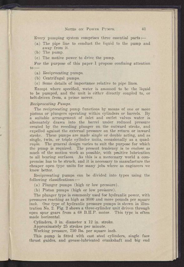
pressures reaching as high as 3000 and more pounds per square inch. One type of hydraulic pressure pumps is shown in illus-tration No. 2. Fig. 2 shows a three-cylinder unit driven through open spur gears from a 68 B.H.P. motor. This type is often made horizontal.
Cylinders, 3 in. diameter x 12 in. stroke. Approximately 25 strokes per minute. Working pressure, 750 lbs. per square inch. This pump is fitted with cast steel cylinders, single face
thrust guides, and grease-lubricated crankshaft and big end
r
42 VICTORIAN INSTITUTE OF ENGINEERS.
bearings, the crankshaft being hollow drilled, and the grease forced through by an automatic intensifier. The driving motor
Fig. 2. should be operated in one direction on account of the thrust guides.
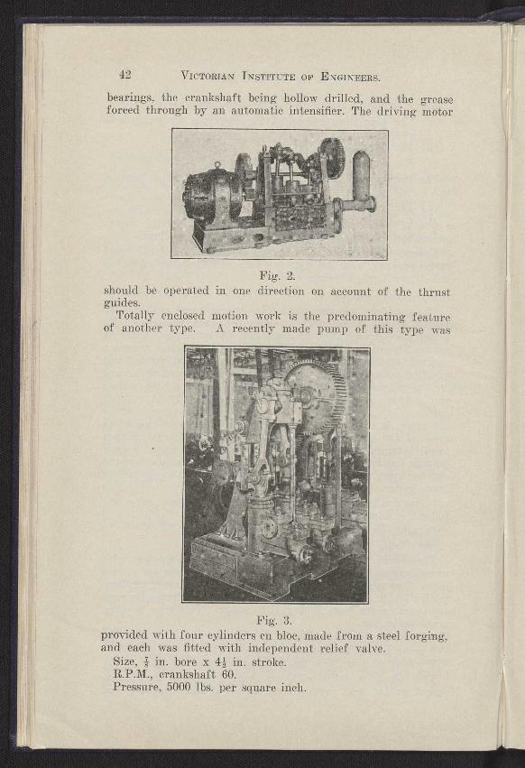
Totally enclosed motion work is the predominating feature of another type. A recently made pump of this type was
Fig. 3. provided with four cylinders en bloc, made from a steel forging, and each was fitted with independent relief valve.
Size, s in. bore x 42 in. stroke. R.P.M., crankshaft 60. Pressure, 5000 lbs. per square inch.
NOTES ON POWER PUMPS. 43
A medium pressure plunger pump is shown in Fig. 3. The particular unit has three cylinders, with a trunk guide for each plunger. The direction of rotation for this type is not of importance. This type is usually fitted with semi-automatic lubrication that needs attention about once an hour.
The types of plunger pump shown in Fig. 2 are usually only adopted for supplying hydraulic power for presses and similar applications, whilst those illustrated in Fig. 3 are used where
ma.
__..__ ~~~.a~~~ 1
.. . \ 9à
n„eaws~
Ì%u~
.✓~ ~,~r~~~j~■~~
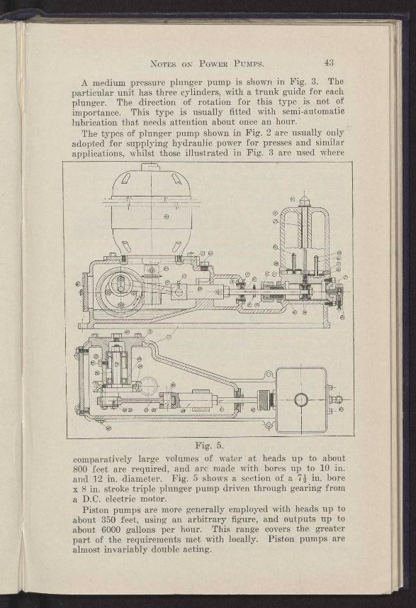
Fig. 5.
comparatively large volumes of water at heads up to about 800 feet are required, and are made with bores up to 10 in. and 12 in. diameter. Fig. 5 shows a section of a 71. in. bore x 8 in. stroke triple plunger pump driven through gearing from a D.C. electric motor.
Piston pumps are more generally employed with heads up to about 350 feet, using an arbitrary figure, and outputs up to about 6000 gallons per hour. This range covers the greater part of the requirements met with locally. Piston pumps are almost invariably double acting.
44 VICTORIAN INSTITUTE OF ENGINEERS.
A type of piston pump suitable for unattended automatic operation .is made with a reduction gear, and trunk guide for the crosshead in an enclosed oil bath.
Whilst I have given briefly the main types of reciprocating pumps, no mention has been made as to how or why the different types have been evolved. Primarily it is a case once again of the survival of the fittest. Let us examine the design of the first illustration shown of an open type hydraulic pump. The massiveness of the machine is the first particular noticed ; secondly, the long stroke to bore ratio adopted, and, thirdly, the comparatively slow piston speed. It would be thought that if instead of a stroke to bore ratio 4 : 1 a ratio of 2 : 1 was adopted, it would be a cheaper job to build. Actually this is not so, for if a 2 : 1 ratio be adopted a much heavier crank-shaft would be required, as the bending moment is more than doubled, and the crankshaft bearings, stanchions, and base and big ends would all have to be correspondingly enlarged.
With a 3 in. diameter plunger and 12 in. stroke the total bearing load on each big end is approximately 5250 lbs., and the bending moment about the external cranks amounts to 61,000 inch lbs. If a 2 : 1 stroke to bore ratio for the same output be adopted, the big end load and the corresponding crank bending moments would be approximately 9000 lbs. and 114,300 inch lbs. respectively.
The types totally enclosed are very suitable for unattended automatic running in dusty atmospheres. They are entirely self-lubricating, but are a much more expensive unit to manufacture. The life and freedom from breakdown are greater than that of the previous type.
The design of the unit shown in Fig. 3 permits of a rela-tively short stiff crankshaft, and correspondingly allows of larger plunger diameters. The wear on the trunk guides and neck rings is often rapid, due to difficulty in lubrication with heavy thrust loading. The trunk guides in some installations, require remetalling or bushing about every 2+, to 3 years through operating in a dusty atmosphere.
The types shown in Fig. 5 originated in America, and over come many of the disabilities of small household water supply systems. This design permits of operating speeds up to 350 R.P.M. of the crankshaft, and sometimes even 500 R.P.M. is adopted. These high speeds call for adequate "cushioning" of the piston by means of the water containing a large amount of free air, and also large valve areas are a necessity.
The limiting factor in design for the permissible number of strokes per minute is mainly inertia. The piston speed is controlled by the ability of the liquid to follow it, and there is quite a characteristic knock introduced when this value is

NOTES ON POWER PUMPS. 45
exceeded. The ability of the liquid to fill the cylinder sufficiently fast is assisted by two factors :-
(a) Large inlet valves offering a minimum resistance. (b) Placing a relatively large air chamber over the inlet .
valves, thereby tending to keep the liquid in the suction pipe flowing continuously.
Retarding the available velocity of flow are :- (c) The viscosity of the liquid. (d) The suction lift. There are two other factors which affect the available
suction lift that a pump can be operated with safety, as well as the piston speed. These factors are the vapour pressure of the liquid, and secondly the amount of gas that is dissolved in the liquid, together with the rate at which it comes out of solution. Factors Affecting Suction Lift.
As a reciprocating pump is a positive displacement machine, it is usually considered as being self priming up to fairly large suction lifts, say to 20 ft. with cold water. This is only partly true.
The ability to prime is determined by the volumetric clear-ance and the pressure against which the air has to be discharged. I have seen many installations where the clearance volume and the discharge pressure have been such that it is impossible for the pump to clear itself of air. The cure in such a happening is to fit a non-return valve close to the pump in the delivery pipe and a small by-pass valve that opens to atmosphere. This will permit the pump to void itself of some of the air, and possibly prime itself. The maximum suction lift against which a pump will prime is ultimately dependent upon the ratio of the volumetric clearance to the total cylinder volume, the baro-metric pressure, and the vapour pressure of the liquid to be pumped.
The foregoing discussion does not imply that a pump that cannot prime itself is unsuitable for working on a high suction lift. I know of different types made by various manufacturers that cannot prime themselves with only a six feet suction lift, but can work on a 26 feet suction lift when primed with a volumetric efficiency of over 90% when operated on clear cold. water not exceeding 85° F. These features of a suction lift limitation are not generally realised, and have frequently caused much worry to operators. Characteristics of Operation.
Because of its method of operation a reciprocating pump is inherently a constant volume pump except for a small slip caused by the water not following the plunger owing to excessive speed, and the valves not closing quick enough. The
46 VICTORIAN INSTITUTE OF ENGINEERS.
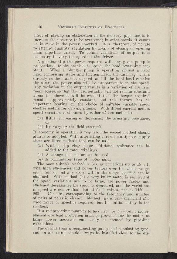
effect of placing an obstruction in the delivery pipe line is to increase the pressure to be overcome ; in other words, it causes an increase in the power absorbed. It is, therefore, of no use to attempt quantity regulation by means of closing or opening main pipe-line valves. To obtain variations of output it is necessary to vary the speed of the driver.
Neglecting slip the power required with any given pump is proportional to the crankshaft speed, the head remaining con-stant. When a plunger pump is operating against a fixed head comprising static and friction head, the discharge varies directly as the crankshaft speed, and if the total head remains the same, the power also will be proportionate to the speed. Any variation in the output results in a variation of the fric-tional losses, so that the head actually will not remain constant. From the above it will be evident that the torque required remains approximately constant, and this feature has an important bearing on the choice of suitable variable speed electric motors for driving pumps. With direct current motors speed variation is obtained by either of two methods
(a) Either increasing or decreasing the armature resistance, or
(b) By varying the field strength. If economy in operation is required, the second method should always be adopted. With alternating current multiphase supply there are three methods that can be used :-
(a) With a slip ring motor additional resistance can be added to the rotor windings.
(b) A change pole motor can be used. (c) A commutator type of motor used. The most suitable method is (c), as variations up to 15 : 1,
with high efficiencies and power factors over the whole range, are obtained, and any speed within the range specified can be obtained. With method (b) a very bulky motor is required if the speed variations are to be large, the power factor and efficiency decrease as the speed is decreased, and the variations in speed are not gradual, but at fixed values such as 1450 -960 — 750, etc., corresponding to the frequency and number of pairs of poles in circuit. Method (a) is very inefficient if a wide range of speed is required, but the initial outlay is the smallest.
If a reciprocating pump is to be driven by an electric motor, efficient overload protection must be provided for the motor, as large power increases can easily be created by pipe-line restrictions.
The output from a reciprocating pump is of a pulsating type, and an air vessel should always be installed close to the dis-
NOTES ON POWER PUMPS. 47
charge valves with some method of keeping it charged with air. It is important that the air vessel be of adequate size. There is quite a lot of misunderstanding about the air vessels fitted to plunger pumps, and many engineers think that because an air vessel has been fitted by the manufacturer it is sufficiently large to ensure protection for any pipe line in which the pump could be installed. For instance, a certain pump was designed and fitted with an air vessel which was proved adequate for a 11 in. diameter pipe line 150 feet long. A similar pump was installed without the purchaser giving pipe line particulars, and trouble was immediately encountered on starting. The pipe line in this instance was 180 feet long and 2 in. diameter with the same volume of water flowing, but to eliminate water hammer an additional air chamber of .5 cubic feet was required. High-speed short-stroke plunger pumps tend to produce more intensive water hammer than low-speed long-stroke units.
Water hammer is caused by a change of velocity of flow in a pipe line, the change occurring in less time than is required for a sound wave to travel through to the water to the end of the pipe line and back. A sound wave travels through water at the rate of 4200 feet per second, so that the rate of velocity change necessary to produce water hammer varies with every installation. The force of the water hammer blow is between 54 and 63 pounds per foot sudden change in velocity of flow, varying with the elasticity of the pipe.
When an air vessel of adequate size is installed it protects the pump and pipe line by acting as a reservoir for smoothing out minor variations in flow from. the pump, and at the same time providing a cushion for the energy of a hammer wave to expend itself by compressing the enclosed volume of air. The size of air vessel required is determined by :-
(a) The maximum head the pump has to function against. (b) The length and diameter of the pipe to which it is
connected. (e) The intensity of a probable hammer blow.
It is possible for the pump designer to decide approximately upon (a) and (e), but he cannot anticipate (b).
On all pipe lines in excess of 150 to 200 feet the possibilities of water hammer occurring should be considered and the necessary precautions taken. Water hammer can occur in a pipe line without giving violent manifestation of its presence, nevertheless causing excessive wear on the big end bearings and failure of the pump gaskets and valves.
The efficiency of any machine is the ratio of the useful work done to the energy input, and for a water pump it is expressed
48 VICTORIAN INSTITUTE OF ENGINEERS.
as the ratio of the hydraulic horse power output to the brake horse power input. With well-designed reciprocating pumps the efficiency ranges from approximately 50% with a discharge of 10 G.P.M. up to 85 and 90% on large units. The losses of power which are not recoverable are
(a) Mechanical losses, such as bearing friction and gearing losses. Acceleration each stroke of the masses of the plunger and connecting rods.
(b) The acceleration and deceleration of the liquid each stroke of the plunger. Loss of head through passage ways and valves.
The mechanical losses do not vary directly with the water horse power, and as the hydraulic loading is increased to the maximum value for which the pump is designed, the proportion of power dissipated decreases with a corresponding increase in the efficiency and economy of the plant.
Centrifugal Pumps. Compared with the reciprocating type, centrifugal pumps
are of comparatively modern origin, as it is only a matter of approximately seventy years in which this type has been developed, and the major development has occurred in the last twenty-five years. One leading authority on the subject intro-duced his book with the statement "that centrifugal pumps have more tricks than a circus mule, and also more obstinacy." This particular book was published approximately fifteen years ago, but since then their propensities have come to be much better understood.
An elementary centrifugal pump comprises a rotating element or impellor, suitably mounted on bearings, with pas-sages radiating from the centre to the periphery. Water is conducted to the centre of this rotating element, and by cen-trifugal force it is expelled into a collecting chamber, from whence it enters the discharge piping. Nothing else about a centrifugal pump can be called elementary however. The rotat-ing element is usually called the impellor or rotor, and the collecting chamber referred to as the casing or stator.
The design of a reciprocating pump is comparatively a matter of determining the strengths of various parts; as the output is constant for a given speed irrespective of the head, neglecting slip ; consequently there is not very much mathematical work to be done. In a centrifugal pump the amount of mathematical analysis is very considerable, and can be very involved if the complete characteristic of operation is to be predicted. The output alters with each change of head, the speed remaining constant, and such variation is governed by the design of the impellor blades and passages in conjunction with the casing.
NOTES ON POWER PUMPS. 49
Before discussing the mathematical design it may be of interest to trace rapidly the evolution of this type of pump.
The very early centrifugal pumps consisted of a circular casing with the outlet either central or tangential. The rotor blading was vanes radiating from the centre. The general design is still used in cheap blower fans for forge fires. This type had a very low efficiency, and small variations in head produced large variations in power unless the speed was adjusted. The next step in progress was made when it was found that if the vanes sloped backwards at the outlet the power did not vary so much with variations in head, and neither did the output increase as much. Shortly after this discovery it was found that if a diffusion chamber was fitted in the casing at the outlet of the impellor, and so shaped that the absolute velocity of discharge was gradually reduced, a greater head could be developed by the pump for the same peripheral speed of the impellor. The application of the dif-fusion chamber immensely improved the operation and paved the way for the turbine type of centrifugal pump. In the turbine type diffusion passages are fitted into the casing around the outlet of the impellor. The entrant ends of the passages are designed so that the mean angle of entry is equal to the angle of the absolute velocity of discharge from the impellor and the passageways gradually increase in area, correspondingly decreasing the velocity of flow. The design of the impellor blading was constantly changing, and three types were in common usage—backward curving, forward curving, and radial at the outer edge of the impellor. These three types are still used in fans, which, after all, are only a specialised form of centrifugal pump for handling a gas instead of a liquid.
It was noticed that a turbine pump when carefully designed gave a higher efficiency than a pump of that period with a vaneless diffuser, but that the vaneless diffuser pump held its efficiency over a much larger range. Inspection of the velocity diagram shows that for any speed the diffuser blading can only be correct for one rate of discharge, and that at all other rates they actually form an added obstruction which causes losses.
The volute type of centrifugal pump was developed to over-come this disadvantage, and as now known there are two distinct types, but as the principles are the same, only the method of application varying, one description will suffice. In the type developed for general work the volute takes the form of an expanding scroll, the area of which is proportional to the distance from the starting point. This permits the impellor to discharge uniformly from the periphery into the scroll. The velocity of flow chosen is such that the sum of the losses is kept to a minimum. Backward sloping vanes are almost.
50 VICTORIAN INSTITUTE OF ENGINEERS.
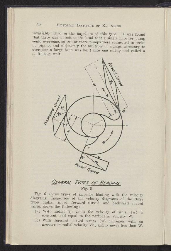
invariably fitted in the impellors of this type. It was found that there was a limit to the head that a single impellor pump could overcome, so two or more pumps were connected in series by piping, and ultimately the multiple of pumps necessary to overcome a large head was built into one casing and called a multi-stage unit.
QENER4L TYPES OF 5LAD/NCB
Fig. 6.
Fig. 6 shows types of impellor blading with the velocity diagrams. Inspection of the velocity diagrams of the three types, radial tipped, forward curved, and backward curved vanes, shows the following
(a) With radial tip vanes the velocity of whirl (w) is constant, and equal to the peripheral velocity W.
(b) With forward curved vanes (w) increases with an increase in radial velocity Vr., and is never less than W.
NOTES ON POWER PUMPS. 51
(c) With backward curved vanes (w) decreases with an increase in radial velocity Vr., and is never greater than W.
The head developed by an impellor, from which all casing losses are to be deducted is
Hmkp-
— -
32 where kp is a co-efficient depending upon the diameter of the impellor and the number of blades, consequently neglecting the inlet and casing design, the characteristics are :-
Radial tips : Head tends to remain constant irrespective of discharge, but when overload control is attempted with a high efficiency a period of instability of operation is encountered just before the maximum efficiency point.
Forward curved : The power absorbed rises rapidly with an increase in output. Head tends to rise as capacity increases. Absolute velocity of discharge very high with consequent large losses in the casing. Power rises rapidly with increase in capacity.
Backward curved : Head tends to drop as capacity increases. Absolute velocity of discharge reasonably low, and a large conversion of kinetic to potential energy possible in the casing. Power rise with increase in capacity comparatively easily controlled without adversely affect- ing the maximum efficiency obtainable.
Every designer of centrifugal pumps has his own methods of design and analysis of test results. When a variation of design is made it is based usually upon rather extensive analysis of previous tests, and it is possible, in fact probable, that if two designers independently examined a set of curves they would come to different conclusions on some detail of impellor or casing design. I think, however, that it is agreed that the only method of designing efficient contrifugal pumps is by constantly testing known designs in which one feature has been altered and then analysing the result. For convenience the test results are usually graphed and show the following curves :
(a) Head quantity at a constant R.P.M., (b) the B.H.P. at that R.P.M., (c) the pump efficiency, and preferably the suction lifts on
which the tests were conducted. These curves can be . divided into many types, but they fit
into two classes naturally when the power curve is the basis of comparison. If the power curve continues rising as the head falls it is classed as an overloading characteristic, and if it flattens out and does not rise much with a fall in head,
120
60
40
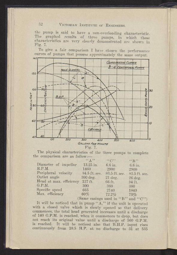
the pump is said to have a non-overloading characteristic. The graphed results of three pumps, in which these characteristics are very clearly demonstrated are shown in Fig. 7.
To give a fair comparison I have chosen the performance curves of pumps that possess approximately the same output.
14
~~
g ~ s~` ~!
_
I ~~,.
Ç MP .:
~~. -AT/Y~
~~~,y•r~r~:~' CU
■ ~
~m~ oawl ■
~ P
~
~ e
.y
MI ESN
.~IAME ratillaNIE4 FialliStal Wilt
_ ■
401
52 VICTORIAN INSTITUTE OF ENGINEERS.
200 o 600
30
0
0
GALLONS PE,Q /1//NUTE
Fig. 7. The physical characteristics of the three pumps to complete
the comparison are as follow:— ,,A ,, << C „ ''B''
Diameter of impellor 13.25 in. 6.6 in. 6.6 in. R.P.M. 1460 2900 2900 Peripheral velocity 84.5 ft. sec. 83.5 ft. sec. 83.5 ft. sec. Outlet angle 360 deg. 21 deg. 26 deg. Head at max. efficiency 127 ft. 66 ft. 94 ft. G.P.M. 300 360 380 Specific speed 665 2140 1840 Max. efficiency 60% 72.2% 73%
(Same casings used in "B" and "C") It will be noticed that in pump "A," if the unit is operated
with a closed valve which is slowly opened so that delivery commences, the total head generated increases until a discharge of 140 G.P.M. is reached, when it commences to drop, but does not reach its original value until a discharge of 360 G.P.M. is reached. It will be noticed also that B.H.P. input rises continuously from 10.5 H.P. at no discharge to 31 at 535

NOTES ON POWER PUMPS. 53
G.P.M., where the test is stopped. This effect is produced by using a high outlet angle with a low radial velocity component in the impellor; the volute velocity also was comparatively low. This type of characteristic has a limited value. The static head has to be lower than the shut-off head, otherwise the pump will not commence to discharge. If the total head, i.e., static plus friction, is greater than the shut-off head, the pump must be started with the valves open. Unless this precaution is taken violent hammering in the pipe line will be induced, because at all values of head above the "shut-off head" there are two possible discharges. This type cannot be used in parallel operation, or for boiler feed duties. Also very efficient overload protection must be provided for an electric motor if used for driving, for in the event of a large variation in head due to a change in levels or a burst pipe a large increase in power takes place.
The characteristic of pump. "B" is such that no large increase in power occurs with variations of head. The rise in head above no discharge is not very pronounced, but the dis-advantages of type "A" are still present, but not so evident. These two types are suitable where a large proportion of the operating head is due to frictional losses in the installation, or as pressure as in spray irrigation work.
Type "C" presents what might be termed a good charac- teristic for general purposes. The power rise is definitely limited, the efficiency is high and is maintained over a wide range, being over 70% from 320 G.P.M. to 410 G.P.M. This type of characteristic is suitable for pumps operating in parallel, for boiler feed duty, etc., and represents the best characteristics of a volute pump, greatly exaggerated through excessive control by induced cavitation.
The disadvantage is that the head produced per impellor is low compared with types "A" and "E." Despite this fact the efficiency is high.
The factors influencing the efficiency of a centrifugal pump are :—
(a) Friction of the disc rotating in the casing. This varies as the fifth power of the diameter.
(b) The friction of the spindle in the bearings and packing. (c) The shock loss at the discharge of the impellor and
entrance to volute passage or diffusion vanes. Shock loss at entry.
(d) The friction of the water in the volute. This can be as high as 15 to 20 feet in a small pump.
(e) The R.P.M. adopted.
54 VICTORIAN INSTITUTE OF ENGINEERS.
When comparing designs of centrifugal pumps it is essential that there be some common basis of comparison in order that true inferences be drawn. The specific speed is often employed for this purpose, and serves the purpose well. The specific speed of a pump represents the R.P.M. that a geometrically similar unit would have to operate to discharge one gallon per minute against a head of one foot, and is obtained from the formula using the values at maximum efficiency as a comparison point.
Specific speed — I G.P.M. R.P.M. x 1 x~
When the specific speed and efficiencies of different types are reviewed there is definitely a common basis of comparison. If a range of geometrically similar pumps of different sizes be tested it will be found that as the pump size is increased the efficiency also increases, but the maximum efficiency occurs at approximately the same specific speed. A pump with a low specific speed is usually a high head low quantity, low or medium speed, and has a large diameter and relatively narrow impellor. Vice-versa a high specific speed pump usually has a small diameter and wide impellor. Within limits the higher the specific speed of the type the higher the efficiency.
The specific speed of the pump links together the operating head, the quantity discharged, and the R.P.M. These factors control the effectiveness of any pump on a suction lift, conse-quently the specific speed can be used for determining the maximum safe suction lift that a given type can be satisfac-torily operated with before cavitation occurs. Some excellent data have been obtained which clearly show the limitations of each type in this respect. Apart from the inherent features of the pump, the possible suction lift is controlled by the same forces as mentioned for reciprocating pumps.
The efficiency of well-designed centrifugal pumps under favourable conditions varies from 40% with a discharge as low as 25 G.P.M. against 60 feet head, up to 85% and higher in the largo sizes.
The designing of a stock centrifugal pump presents more problems than designing for a specific purpose, provided that a high efficiency is to be maintained over a reasonable range. The trade requirements demand that a given size pump will discharge a certain quantity irrespective of whether the head is five feet or 45 feet, but at the same time insists upon a very economical performance at the lower head. This can be allowed for in the design, but only at the expense of sacrificing any inherent overload prevention features that would protect the equipment when operating at the higher head in the event of a burst pipe, or other large variation in head. This, of
NOTES ON POWER PUMPS. 55
course, is objectionable to the manufacturers and suppliers of oil engines and electric motors.
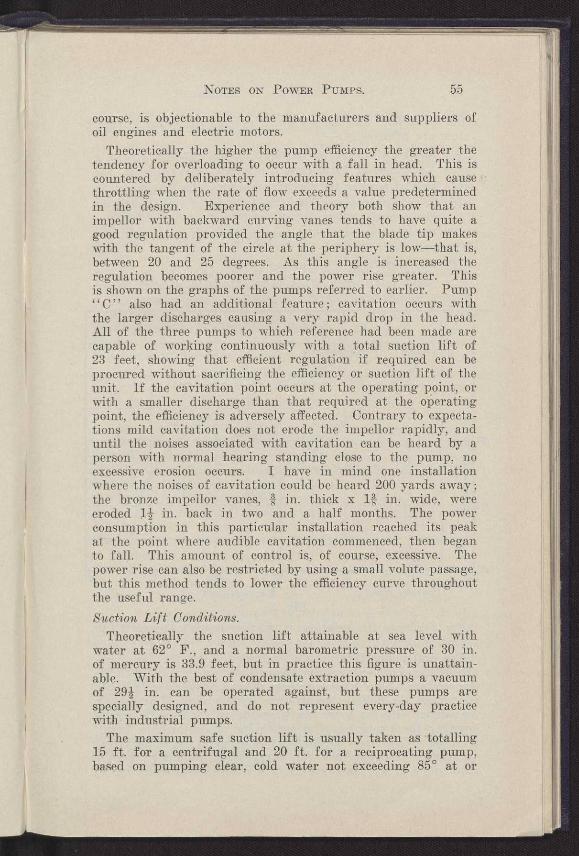
Theoretically the higher the pump efficiency the greater the tendency for overloading to occur with a fall in head. This is countered by deliberately introducing features which cause throttling when the rate of flow exceeds a value predetermined in the design. Experience and theory both show that an impellor with backward curving vanes tends to have quite a good regulation provided the angle that the blade tip makes with the tangent of the circle at the periphery is low—that is, between 20 and 25 degrees. As this angle is increased the regulation becomes poorer and the power rise greater. This is shown on the graphs of the pumps referred to earlier. Pump "C" also had an additional feature; cavitation occurs with the larger discharges causing a very rapid drop in the head. All of the three pumps to which reference had been made are capable of working continuously with a total suction lift of 23 feet, showing that efficient regulation if required can be procured without sacrificing the efficiency or suction lift of the unit. If the cavitation point occurs at the operating point, or with a smaller discharge than that required at the operating point, the efficiency is adversely affected. Contrary to expecta-tions mild cavitation does not erode the impellor rapidly, and until the noises associated with cavitation can be heard by a person with normal hearing standing close to the pump, no excessive erosion occurs. I have in mind one installation where the noises of cavitation could be heard 200 yards away; the bronze impellor vanes, * in. thick x 1* in. wide, were eroded 11 in. back in two and a half months. The power consumption in this particular installation reached its peak at the point where audible cavitation commenced, then began to fall. This amount of control is, of course, excessive. The power rise can also be restricted by using a small volute passage, but this method tends to lower the efficiency curve throughout the useful range. Suction Lift Conditions.
Theoretically the suction lift attainable at sea level with water at 62° F., and a normal barometric pressure of 30 in. of mercury is 33.9 feet, but in practice this figure is unattain-able. With the best of condensate extraction pumps a vacuum of 29* in. can be operated against, but these pumps are specially designed, and do not represent every-day practice with industrial pumps.
The maximum safe suction lift is usually taken as totalling 15 ft. for a centrifugal and 20 ft. for a reciprocating pump, based on pumping clear, cold water not exceeding 85° at or
$UCr/ON HEAO
25
20
50
56 VICTORIAN INSTITUTE OF ENGINEERS.
about sea level. The factors which cause a limitation to these values are principally :—
(a) Head lost due to acceleration of the liquid. (b) Variations of barometric pressure. (c) Loss of head in the suction passages of the pump. (d) A safety margin to allow for leakages of air through the
glands and stuffing boxes. (e) Dissolved gases coming out of solution under reduced
pressure. (f) The vapour pressure of the liquid. The term total suction lift should include all the piping
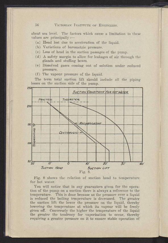
losses on the suction side of the pump.
Sa TiON ONor ioNs OR fMr s f -~-
--°— PRAGrIL EFI RETIC
E ~® --N
11111111111111111166.
1111/1111641■
~ I
~
1~
o ~0'
Sac LIFT Fig. 8.
Fig. 8 shows the relation of suction head to temperature for hot water.
You will notice that in any guarantees given for the opera-tion of the pump on a suction there is always a reference to the temperature. This is done because ag the pressure over a liquid is reduced the boiling temperature is decreased. The greater the suction lift the lower the pressure on the liquid, thereby lowering the temperature at which its vapour will be freely given off. Conversely the higher the temperature of the liquid the greater the tendency for vaporisation to occur, thereby requiring a greater pressure on it to ensure stable operation of
NOTES ON POWER PUMPS. 57
the pump. This means a lower possible suction lift as the temperature of the liquid to be pumped is increased.
When pumping hot water it is desirable to have at least h margin of 14 ft. pressure on the surface of the liquid, above tjie vapour pressure for that particular temperature. The graph shown gives the relation between the practical inlet conditions and the theoretical at temperatures up to 212° F.
When pumping liquids other than water the specific gravity and vapour pressures would have to be taken into account to prepare a similar chart for suction conditions. The viscosity of the liquid also affects the suction lift and general charac-teristic of the pump, but it is to be regarded as an additional factor causing increased frictional loss.
The applications of a pump, whether of reciprocating or centrifugal type, are limited to the practical suction lift, which has been shown to be very curtailed. There are obviously hundreds of instances where these limitations impose difficulties which would appear to be insurmountable.
Overseas firms have developed systems whereby the suction lift can apparently exceed the natural values. Such devices take the form of an auxiliary pump operated by or from the main pump.
One French firm operating under Rateau's patents builds a centrifugal pump of orthodox design, but has an extended spindle on to which a smaller pump is built, and the discharge of this pump operates an ejector. Some years ago the A.C.E.A. Company were building a device to enable a centrifugal pump to operate placed 65 feet above water level, and this unit com-prised a low pressure turbine driving a small impellor which lifted the water up to the normal suction limits of the pump. The main pump provided the water for operating the turbine.
In England a plant was installed in July, 1936, in which a force pump operating a jet pump was elevating 1500 gallons of water per hour from a depth of 265 feet, and was economical enough to be used continually for town water supply duty.
The method which is being employed extensively in Australia and elsewhere successfully, for elevating small discharges from depths beyond the normal suction limits, is shown on illustration No. 9. The system comprises a high pressure centrifugal pump and a specialised form of jet pump usually called an augmentor, interconnected with piping. The augmentor is placed below the pump in the water. The piping is arranged so that a proportion of the water handled by the centrifugal circulates from the discharge through the augmentor back to the suction with an induced volume of water, which is delivered into the desired storage. With this system water can be elevated to large heights above ground level.

Rarn svcie ca°Alvmientbi
Firm dsc/rerye of°Acgyrentq.
-4-0i5c4dnPe
--Confro/ vo/ve
Bemis A
,ltSoogets ovens
•_• `N 111Il.; i Hi L le
Giessure Qou9e
G'o~e G'ocK--Y
Foot-wrYe t strrnr
58 VICTORIAN INSTITUTE OF ENGINEERS.
One plant recently installed on a bore 4i in. inside diameter is lifting 500 gallons per hour from a depth of 60 feet, and elevat-ing it 65 feet, using a 1 H.P. motor. Units can be obtained for depths down to approximately 250 feet, with above ground level heads of 200 feet and greater. The centrifugal pump
Fig. 9.
used must necessarily be of a highly efficient design, or else the system becomes too inefficient. The characteristics of the combined centrifugal pump and augmentor are somewhat similar to the standard conception of a centrifugal pump, except that for any given combination as the total head decreases the B.H.P. input decreases, and the point of maximum hydraulic horse power output represents the point of maximum efficiency.
I have given some of the characteristics of operation of, two classes of power pumps, with the hope that the information will be of interest and value to the members of this Institute.
ERRATA-POWER PUMPS. 81
ERRATA.
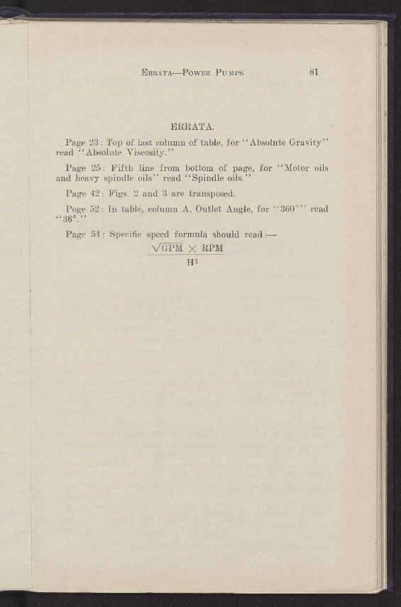
Page 23: Top of last column of table, for "Absolute Gravity" read "Absolute Viscosity."
Page 25: Fifth line from bottom of page, for "Motor oils and heavy spindle oils" read "Spindle oils."
Page 42: Figs. 2 and 3 are transposed.
Poge 52: In table, column A, Outlet Angle, for "360°" read 4C 360:1
Page 54 : Specific speed formula should read VGPM X RPM
Hs
Library Digitised Collections
Author/s:Robison, A. B.
Title:Some notes on power pumps (Paper)
Date:1940
Persistent Link:http://hdl.handle.net/11343/24831
Related Documents