Central Washington University ScholarWorks@CWU Electronic eses Student Scholarship and Creative Works 1953 Some Interesting Projects in Foundry Paul M. Paulson Central Washington University Follow this and additional works at: hp://digitalcommons.cwu.edu/etd Part of the Art Education Commons , and the Teacher Education and Professional Development Commons is esis is brought to you for free and open access by the Student Scholarship and Creative Works at ScholarWorks@CWU. It has been accepted for inclusion in Electronic eses by an authorized administrator of ScholarWorks@CWU. Recommended Citation Paulson, Paul M., "Some Interesting Projects in Foundry" (1953). Electronic eses. Paper 112. brought to you by CORE View metadata, citation and similar papers at core.ac.uk provided by ScholarWorks at Central Washington University

Welcome message from author
This document is posted to help you gain knowledge. Please leave a comment to let me know what you think about it! Share it to your friends and learn new things together.
Transcript

Central Washington UniversityScholarWorks@CWU
Electronic Theses Student Scholarship and Creative Works
1953
Some Interesting Projects in FoundryPaul M. PaulsonCentral Washington University
Follow this and additional works at: http://digitalcommons.cwu.edu/etd
Part of the Art Education Commons, and the Teacher Education and Professional DevelopmentCommons
This Thesis is brought to you for free and open access by the Student Scholarship and Creative Works at ScholarWorks@CWU. It has been accepted forinclusion in Electronic Theses by an authorized administrator of ScholarWorks@CWU.
Recommended CitationPaulson, Paul M., "Some Interesting Projects in Foundry" (1953). Electronic Theses. Paper 112.
brought to you by COREView metadata, citation and similar papers at core.ac.uk
provided by ScholarWorks at Central Washington University

-..
SOME INTERESTING PROJECTS IN FOUNDRY
by
Paul M. Paul son
A paper submitted in partial fulfillment of the requirements for the degree of Master of Education, in the Graduate School of the Central Washington College of Education
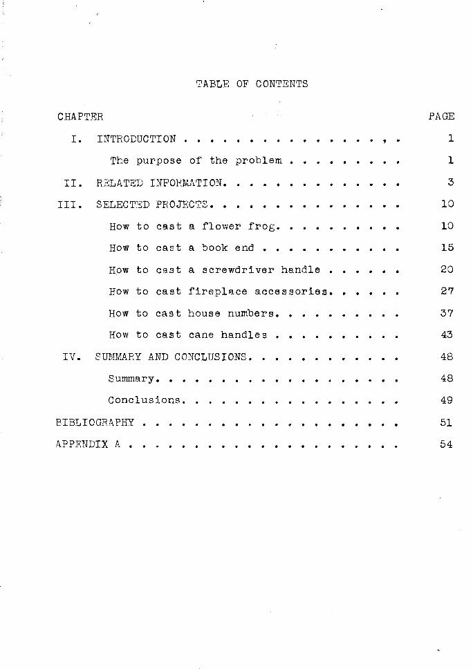
TABLE OF CONTENTS
CHAP'rER
I.
II.
III.
IV.
INTRODUCTION . . . . . . . . . . . . . ' . The purpose of the problem • . . . . . . . .
RELATED INFORMATION. .
SELECTED PROJECTS •••
• • • • • . . . . . . . • • . . . . . . . . . .
How to cast a flower frog. • • • . . . . How to cast a book end • • • . • . . . • • •
How to cast a screwdriver handle . • . • • •
How to cast fireplace accessories. . • . • . How to cast house numbers. • . . . • . . . •
How to ca.st cane handles . • . . . . . . . . SUMMARY AND CONCLUSIONS •. . . . . . . . . . .
Summary ••••• . . . . . . . . . . Conclusions. . .
BIBLIOGRAPffY •
APPENDIX A ••
. . . . . . . . . . .
. . . . . . . . . . . . . . .
PAGE
l
1
3
10
10
15
20
27
37
43
48
48
49
51
54

CHAPTER I
INTRODUCTION AND PURPOSE OF THE STUDY
Foundry work is one of the largest branches of the
metal working industries but still it is ignored by many of
our schools today. Numerous reasons are given, such as lack
of space, high cost of equipment and the dangers involved.
Modern equipment and methods have outmoded these excuses.
Jonesl claims an alert teacher can locate and purchase or
even make any foundry equipment and supplies to meet the
school budget if he so desires.
The purpose of this study is to acquaint industrial
arts teachers with some projects and practices of foundry
work as a possible part of their industrial arts program.
One of the most persistent problems which faces the in
dustrial arts teacher is the selection of suitable projects
for his classes. Students should be encouraged to choose
and even design their own projects but experienced teachers
know that this is not possible with all students. Wilbur2
writes that it is therefore necessary the instructor have
lMervyn T. Jones, "Foundry Work in the Junior High School," Industrial Arts and vocational Education, 40:414;/ December, 1951. ~~ ~-
2Gordon o. Wilbur, Industrial Arts in General Education (Scranton: Haddon Craftsmen, Inc.,-Y-948), p. arr;

2
on hand a list of "type projects" from which a choice can be
made that is suited to the grade level and ability of the
students.
Students of the junior high school level are extremely
enthusiastic about foundry work and there are almost un
limited possibilities in th~s field. No student needs to be
neglected in this area. Projects can be developed to meet
the individual abilities of each student so he may feel some
measure of success and accomplishment.
It is gratifying to watch the look of anticipation
upon a student's face when he is about to break open a mold
that has been recently poured. The entire class is as eager
to see the results of the casting as the person who made the
mold. Parents are also pleased when their child brings home
an attractive and useful project which has been made in the
foundry area.
Practical foundry projects and techniques are divided
into six areas in the following pages. Descriptive pictures
are conveniently located at the end of each project unit.
Periodic reference to these pictures will aid the reader in
a better understanding of the techniques used to produce the
castings.
The terms and their definitions used in this project
are contained in Appendix A.
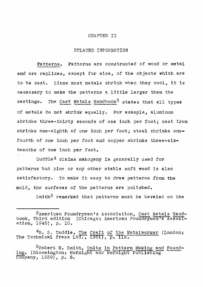
CHAPTER II
RELATED INFORMATION
Patterns. Patterns are constructed of wood or metal
and a.re replicas, except for size, of the objects which are
to be ca.st. Since most metals shrink when they cool, it is
necessary to make the patterns a little larger than the
castings. The Cast Metals Handbook3 states that all types
of metals do not shrink equally. For example, aluminum
shrinks three-thirty seconds of one inch per foot; cast iron
shrinks one-eighth of one inch per foot; steel shrinks one-
fourth of one inch per foot and copper shrinks three-six-
teenths of one inch per foot.
Duddle4 claims mahogany is generally used for
patterns but pine or any other stable soft wood is also
satisfactory. To make it easy to draw patterns from the
mold, the surfaces of the patterns are polished.
Smith5 remarked that patterns must be beveled on the
3American Foundrymen 1 s Association, Cast Metals Handbook, Third edition (Chicago: American Foundrymen's Assoclation, 1945), p. 10.
4R. s. Duddle, The Craft of the Metalworker (London: The Technical Press Lta:-; 1951),-p.~2.
5Robert E. Smith, Units in Pattern Making and Founding. (Bloomington: McKnight and~cKnight Publishing Company, 1939), p. 5.
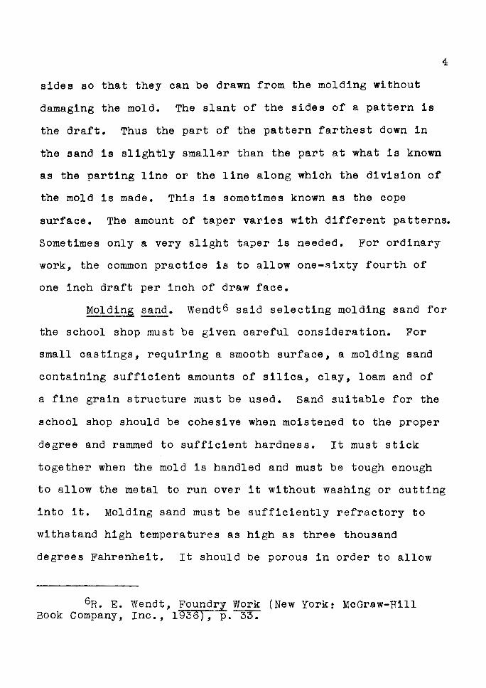
sides so that they can be drawn from the molding without
damaging the mold. The slant of the sides of a pattern is
the draft. Thus the part of the pattern farthest down in
the sand is slightly smaller than the part at what is known
as the parting line or the line along which the division of
the mold is made. This is sometimes known as the cope
4
surface. The amount of taper varies with different patterns.
Sometimes only a very slight taper is needed. For ordinary
work, the common practice is to allow one-sixty fourth of
one inch draft per inch of draw face.
Moldin~ sand. Wendt6 said selecting molding sand for
the school shop must be given careful consideration. For
small castings, requiring a smooth surface, a molding sand
containing sufficient amounts of silica, clay, loam and of
a fine grain structure must be used. Sand suitable for the
school shop should be cohesive when moistened to the proper
degree and rammed to sufficient hardness. It must stick
together when the mold is handled and must be tough enough
to allow the metal to run over it without washing or cutting
into it. Molding sand must be sufficiently refractory to
withstand high temperatures as high as three thousand
degrees Fahrenheit. It should be porous in order to allow
6R. E. Wendt, Found~ work (New York: McGraw-Hill Book Company, Inc., 1936), p.~
5
the fr~e escape of all steam and gases that are generated
when the mold is poured. The sand should be strong so it
will not wear out quickly or crumble when subjected to heat.
Tempering of sand. Ylendt 7 claims the tempering of
sand means the mixing of the sand with water to the proper
degree of dampness. If there is more ·moisture in the sand
than can be driven out when the mold is poured, the metal
may be blown out by the steam formed. If the sand is too
dry, it may drop out of the flask when the mold is handled,
or the metal is likely to cut into the sand and cause sand
holes in the castings.
Preparing the sand. Smith8 said the best method to
test for proper temper is to grasp a handful of sand and
squeeze it into a lump. Break the lump, and if the edges
of the broken surf ace remains sharp and firm, the sand
contains sufficient moisture and is ready for use. If the
edges break and crumble, and the lump falls apart, the sand
is too dry. If the sand makes the hand muddy or if the
sand feels soggy, the sand is too wet. If the sand is too
wet, sprinkle a small amount of dry sand over the pile and
mix thoroughly. Should the sand be too dry, add a little
water and mix thoroughly to eliminate spots in the sand.
7Ibid., pp. 33-34.
8smith, op. cit., p. 33. LibrM}'
Central \Vad1!.n~!;c-n ~oltt\ttl ( '
6
Care of the sand. When the sand is in use every day,
Wendt9 said it will become weak, causing trouble in making
the mold. After the sand has been used a number of times~
the sharp edges have become rounded, partly from wear and
partly from the high temperature of the molten metal. New
sand, which has never been used before, is stronger than it
need be, and when added makes up for the weakening of the
old sand. In this manner, sand may be used over and over
without replacing the whole amount at any time.
After the sand has been used for a time, it will give
better results than when new. Castings from old sand gener
ally will be smoother than those made in all new sand.
Ramming the sand. Stimpson and GraylO claim the
object of ramming is to make the sand hang in the flask and
to support the walls of the mold against the flow and
pressure of molten metals. The knack of ramming just right
comes with continued practice. Hard ramming closes up the
vent, causing blowholes. Soft ramming leaves a weak mold
surface and will tend to make the casting larger than the
pattern and leave bulges or lumps on the casting.
Work
9wendt, op. cit., p. 34.
lOwilliam c. Stimpson and Burton L. Gray, Foundr~ (Chicago: American Technical Society,- 1940), p. 2 •
7
Venting the mold. Stimpson and Grayll also said there
is a considerable amount of air, steam and gas in the molds
which must be driven out of the sand when the metal is
poured; otherwise, blowholes will occur. It is important
that these gases pass off quickly and as completely as
possible. If they do not find free escape through the mold
they are forced back into the liquid metal in the mold
causing the metal to boil or blow. This reaction may cause
the metal to blow out through the risers or simply form
numerous little bubble-shaped cavities in the casting called
blowholes.
The molder cannot depend entirely upon the porosity
of the molding sand, but must provide vents or channels for
the escape of these gases. For light work, the use of the
vent wire through the sand in the cope will 'serve the
purpose.
Stimpson and Grayl2 again said that on castings of
medium weight, risers are placed directly on the casting or
just off to one side. Gates are connected to the mold from
the riser. These risers are left open when the mold is
poured and provide for the escape of the air from the mold.
llstimpson and Gray, loc. cit.
12stimpson and Gray, op. cit., p. 27.
8
The major reason for risers on castings is to compensate for
the liquid shrinkage which occurs while the casting solidi
fies.
Parting materials. Wendtl3 claims that almost all
molds are made in parts, that is to say, one part is made on
top of the other. The sand between the cope and drag will
stick together unless a parting material is put between the
two sections. The most common sand used for this purpose is
called parting sand. This sand contains little or no clay.
Some molders prefer burned core sand or burned sand that is
cleaned from the castings. Any of these sands are suitable.
There are also some manufactured parting compounds but they
cost more than parting sands. These commercial parting
compounds are not used so much commercially but are more
convenient for the school shops than parting sands.
Preparing the metal. Smithl4 remarked that metals
with low melting points, such as lead and type metal can be
melted in an iron pot or ladle over a bench gas furnace.
The melting of metals such as aluminum and brass requires
a ceramic crucible and a forced draft type of melting
furnace. Coal forges and electric furnaces are other ways
13 Wendt, op. cit., p. 38. - --14 Smith, op. cit., p. 44.
9
for melting metals in the school shop.
The temperature of the molten metal may be determined
with a pyrometer equipped with a lance or feeler. The lance
is inserted into the metal; the temperature registered may
then be read on the dial of the pyrometer.
Before the metal is poured into the mold, the oper
ator will notice impurities floating on top of the molten
metal. These impurities must be skimmed off preparatory to
pouring.
While pouring, flow the metal in a steady continuous
stream. Continue pouring until the metal fills the pouring
basin or sprue to the top. If the casting is thin, be sure
to pour the hot metal rapidly.
Safety. Smithl5 also said the melting pot must be
free from moisture, or steam is likely to explode the metal.
safety goggles, asbestos apron and asbestos gloves should
always be worn by the individual while pouring molten metals.
A further safety precaution is to make sure that the path
from the furnace to the mold is clear before any metal is to
be poured. Other students should be instructed to stay away
from the area while the pouring operation is taking place.
16 Smith, op. cit., p. 45.
CHAPTER III
SELECTED PROJECTS
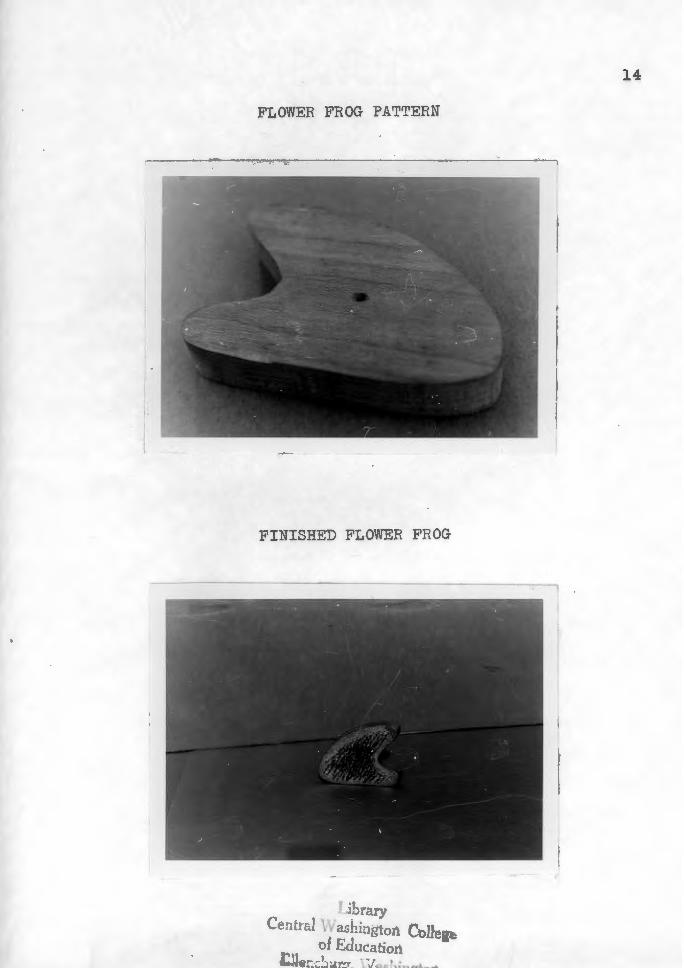
How to Cast a Flower Frog
The flower frog is a unique project which a student
can make in a short period of time. This project is popular
during the seasons when cut flowers are in abundance. Frog
patterns of all shapes and sizes can be easily made.
Procedure for making the pattern.
1. Determine the size and shape of the flower frog.
2. Select a piece of stock, preferably mahogany,
pine, or any stable soft wood, to make the
pattern.
3. Saw the selected stock to size.
4. Fill all holes with putty or wood filler.
5. Apply one or two coats of shellac.
Procedure for casting ~ flower frog.
1. Place the pattern and the drag on the molding
board with the pins of the drag in a downward
position.
2. Dust the molding board and pattern thoroughly
with parting powder.
3. Riddle molding sand over the pattern to a depth
11
of one inch or more.
4. Tuck the sand around the pattern with the fingers
into the recesses of the pattern.
5. Shovel sand into the drag until it is heaping
full.
6. Ram the sand with a bench rammer.
7. Strike off the excess sand with a strike off bar.
8. With a vent wire, punch a series of holes in the
sand over and along the edges of the pattern. Do
not punch the holes directly to the pattern, but
approximately one-eighth of one inch away.
9. With the help of an assist~nt, gently turn the
molding boa.rd and the drag completely over until
the drag is facing upward.
10. Remove the molding board.
11. With the bellows, blow all loose sand from the
drag and exposed part of the pattern.
12. Place the cope on the drag.
13. Place the sprue pin about one inch away from one
end of the pattern and the riser pin the same
distance away from the other end of the pattern.
14. Dust parting powder on the surfaces of the mold
ing sand in the drag.
15. Cover the pattern to a depth of one inch or more
with riddled sand.
16. Tuck the sand into the recesses of the pattern
and around the sprue and riser pins.
17. Fill the cope heaping full of unsifted sand.
12
18. Repeat the same operations of ramming the cope as
was done with the drag.
19. Vent the cope as was done with the drag.
20. Remove the sprue pin and riser pin, and with a
slick, cut a pouring basin at one side of the
sprue hole.
21. Pack all loose sand around the sprue and riser
holes before lifting the cope from the drag.
22. Grasp the ears of the cope with each hand and
slowly raise the cope. Lay the cope with its
side on the foundry bench.
23. Blow off any loose sand that may be on the mold
with the aid of the bellows.
24. Moisten the sand next to the pattern with water.
Do not get the sand too wet; otherwise blow holes
may occur in the casting.
25. Drive the draw spike into the pattern. Rap on all
sides of the pin to loosen the pattern.
26. Draw the pattern from the sand.
27. Patch the mold if necessary.
28. With the gate cutter, cut the gates from the
sprue and riser holes to the mold. The gates
should be about three-eighths of one inch deep
and one-half of one inch wide.
13
29. Carefully press brass escutcheon pins or any
suitable non-corrosive nails about one-sixteenth
of one inch in diameter and one and one-half
inches long into the bottom of the mold. Place
the pins close together.
30. Remove all loose particles of sand from the mold
with the bellows.
31. Place the cope over the drag and lower into place.
The cope should be wei,ghted down with a heavy
object before pouring. This is to prevent the
molten metal from escaping between the cope and
the drag of the flask.
32. Pour the mold with type metal or lead and do not
disturb the mold for at least twenty minutes
before removing the casting from the mold.
FLOWER FROG PATTERN
FINISHED FLOWER FROG
I :b··"'ry 4;,_ LC.:..
CentnJ \Vad~i:1gton CoUegi of Edu~a~ion
:Je:::~!A~·~~- l( J a~'-... :
14
15
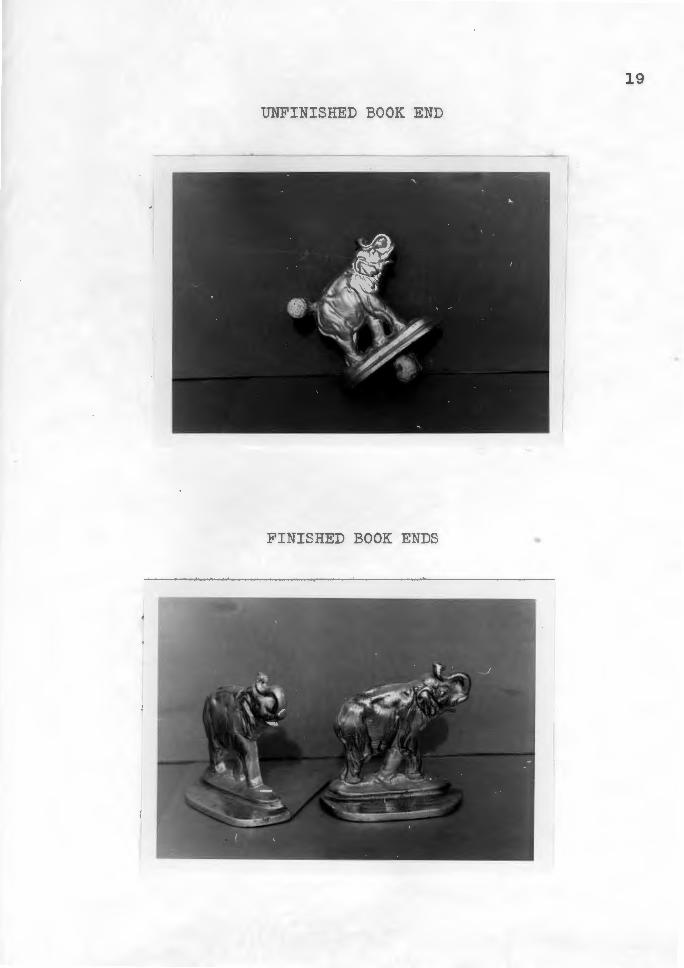
How to Cast a Book End
The book end is another interesting and useful project
which appeals to the students. Any book end with the proper
draft can be used as a pattern. A variety of patterns,
therefore, are always available for the student.
Procedure for making the pattern.
1. Select a pattern.
2. Drill and tap a hole in the heaviest section on
the back side of the pattern for a one-fourth
inch national coarse bolt.
3. Smooth all surfaces with a fine grade of steel
wool or other suitable abrasive.
Procedure for casting the book end.
1. Place the pattern and the drag on the molding
board with the pins of the drag in a downward
position.
2. Dust the molding board and pattern thoroughly
with parting powder.
3. Riddle molding sand over the pattern to a depth
of one inch or more.
4. Tuck the sand around the pattern with the fingers
into the recesses of the pattern.
5. Shovel sand into the drag until it is heaping
full.
16
6. Ram the sand with a bench ramm.er.
7. strike off the excess sand with a strike off bar.
8. With a vent wire, punch a series of holes in the
sand over and along the edges of the pattern. Do
not punch the holes directly to the pattern, but
approximately one-eighth of one inch away.
9. With the help of an assistant, gently turn the
molding board and the drag completely over until
the drag is facing upward.
10. Remove the molding board.
11. With the bellows, blow all loose sand from the
drag and exposed part of the pattern.
12. Place the cope on the drag.
13. Locate and place the sprue pin about one inch
away from the pattern.
14. Place a riser over or adjacent to the heaviest
section of the casting.
15. Dust parting powder on the surface of the molding
sand in the drag.
16. Cover the pattern to a depth of one inch or more
with riddled sand.
17. Tuck the sand into the recesses of the pattern
and around the sprue and riser pins.
18. Fill the cope heaping full of unsifted sand.
19. Repeat the same operations of ramming the cope as
was done with the drag.
20. Vent the cope as was done with the drag.
21. Remove the sprue pin and riser pin qnd, with a
slick, cut a pouring basin at one side of the
sprue hole.
22. Pack all loose sand around the sprue and riser
holes before lifting the cope from the drag.
23. Grasp the ears of the cope with each hand and
slowly raise the cope. Lay the cope with its
side on the foundry bench.
24. Blow off any loose sand that may be on the mold
with the bellows.
25. Moisten the sand next to the pattern with the
bulb sponge.
17
26. Screw the one-fourth inch bolt into the pattern.
Rap on all sides of the bolt to loosen the
pattern.
27. Draw the pattern from the sand.
28. Patch the mold if necessary.
29. With the gate cutter, cut the gates from the sprue
and riser holes to the mold. The gates should be
about one-half of one inch deep and three-fourths
of one inch wide.
30. Remove all loose particles of sand from the mold
with the aid of such tools as trowels, lifters,

18
bulb sponge or bellows.
31. Place the cope over the drag and lower into place.
32. Pour the mold with aluminum and do not disturb
for at least fifteen minutes.
SGNa ~008 aaHSINid
GNa ~008 G~HSINidNll
61
20
How to Cast a Screwdriver Handle
The screw driver is always a favorite project among
the students. Handles for a screwdriver can be made from a
variety of materials, however, the cast aluminum handle is a
popular choice. Design and size of the screwdriver may be
altered to meet the student's choice by constructing a split
pattern from wood.
Procedure for making the pattern.
1. Select two pieces of stock, preferably mahogany,
pine, or any stable soft wood, to make the
pattern.
2. Glue a piece of thin cardboard between the two
pieces and allow to dry.
3. Shape the screw driver handle to the finished
size with the aid of power and hand tools. One
method used to determine the size is to compare
it with a manufactured screw driver.
4. Drill two one-fourth of one inch holes approxi
mately one inch deep at right angles to the
length of the handle for the purpose of pinning
the two halves together.
5. Make two pins from one-fourth of one inch
doweling and round one end of each pin.
6. Pry the two halves of the pattern apart.
21
7. Glue the two pins into the half of the pattern
which has been drilled completely through with the
one-fourth inch drill. Allow one-fourth of one
inch of the dowels to protrude from the flat side
of the pattern for the purpose of fitting the
halves together.
8. Fill all holes with putty or wood filler.
9. Smooth all surfaces with a fine grade of sand•
paper or steel wool.
10. Apply two coats of shellac.
Procedure for casting the screwdriver handle.
1. Place the half of the pattern, without the pins,
and the drag in the molding board with the pins
of the drag in a downward position.
2. Dust the molding board and pattern thoroughly
with parting powder.
3. Riddle molding sand over the pattern to a depth
of approximately one inch.
4. Tuck the sand around the pattern with the fingers
into the recesses of the pattern.
5. Shovel sand into the drag until it is heaping full.
6. Ram the sand with a bench rammer.
7. Strike off the excess sand with a strike off bar.
8. With a vent wire, punch a series of holes in the
22
sand over and along the edges of the pattern. Do
not punch the holes directly to the pattern, but
approximately one-eighth of one inch away.
9. With the help of an assistant, gently turn the
molding board and the drag completely over until
the drag is facing upwards.
10. Remove the molding board.
11. With the bellows, blow all loose sand from the
drag and exposed part of the pattern.
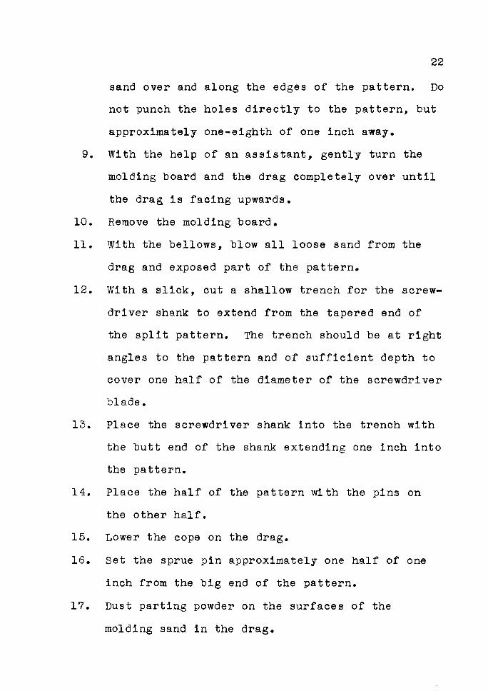
12. With a slick, cut a shallow trench for the screw•
driver shank to extend from the tapered end of
the split pattern. The trench should be at right
angles to the pattern and of sufficient depth to
cover one half of the diameter of the screwdriver
blade.
13. Place the screwdriver shank into the trench with
the butt end of the shank extending one inch into
the pattern.
14. Place the half of the pattern with the pins on
the other half.
15. Lower the cope on the drag.
16. Set the sprue pin approximately one half of one
inch from the big end of the pattern.
17. Dust parting powder on the surfaces of the
molding sand in the drag.
23
18. Cover the pattern to a depth of one inch or more
with riddled sand.
19. Tuck the sand into the recesses of the pattern and
around the sprue pin.
20. Fill the cope heaping full with unsifted sand.
21. Repeat the same operations of ramming the cope as
was done with the drag.
22. Vent the cope as was done with the drag.
23. Remove the sprue pin, and with a slick, cut a
pouring basin at one side of the sprue hole.
24. Pack all loose sand around the sprue and riser
holes before lifting the cope from the drag.
25. Grasp the ears of the cope with each hand and
slowly raise the cope. Lay the cope with its
side on the foundry bench.
26. Blow off any loose sand that may be on the mold
with the bellows.
27. Moisten the sand next to the pattern with water.
Do not get the sand too wet; otherwise blow holes
may occur in the casting.
28. Draw the pattern and screwdriver bit from the
sand.
29. Patch the mold if necessary.
30. With the gate cutter, cut a gate from the sprue
hole to the mold. The gate should be about three-

24
eighths of one inch deep and one-half of one inch
wide.
31. Remove all loose particles of sand from the mold
with the aid of such tools as trowels, lifters,
bulb sponge or bellows.
32. Replace the screwdriver bit back into its origi
nal place in the mold.
33. Place the cope over the drag and lower into place.
34. Pour the mold with aluminum and do not disturb
for at least ten minutes.
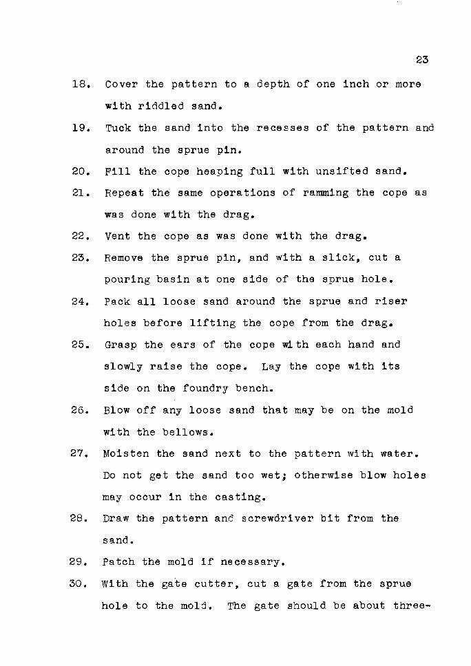
SCREWDRIVER HANDLE PATTERN
UNFINISHED SCREWDRIVER
I.ibrary Ce1l tr al VI a~hi:igton Collegl
of Education I:~lcn::~urJ, Washington
25
26
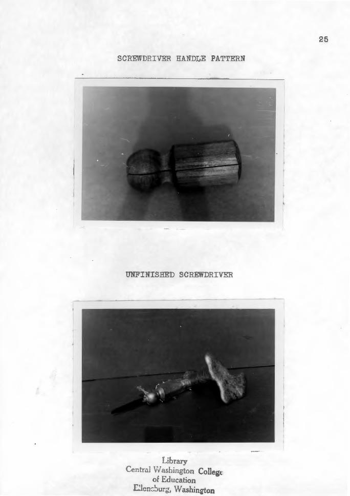
FINISHED SCREWDRIVER
THREE STAGES OF DEVELOPMENT
27
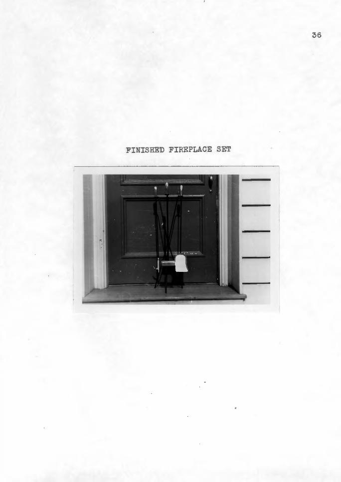
How to Cast Accessories for a Modernistic Fireplace Set
Casting the accessories for a fireplace set offers a
challenge to advanced students who have better than average
abilities in metalcrafts. Not only do the students have to
be proficient in foundry practices and pattern making, but
they must also have considerable abilities in fields of
metals and wood to complete this project.
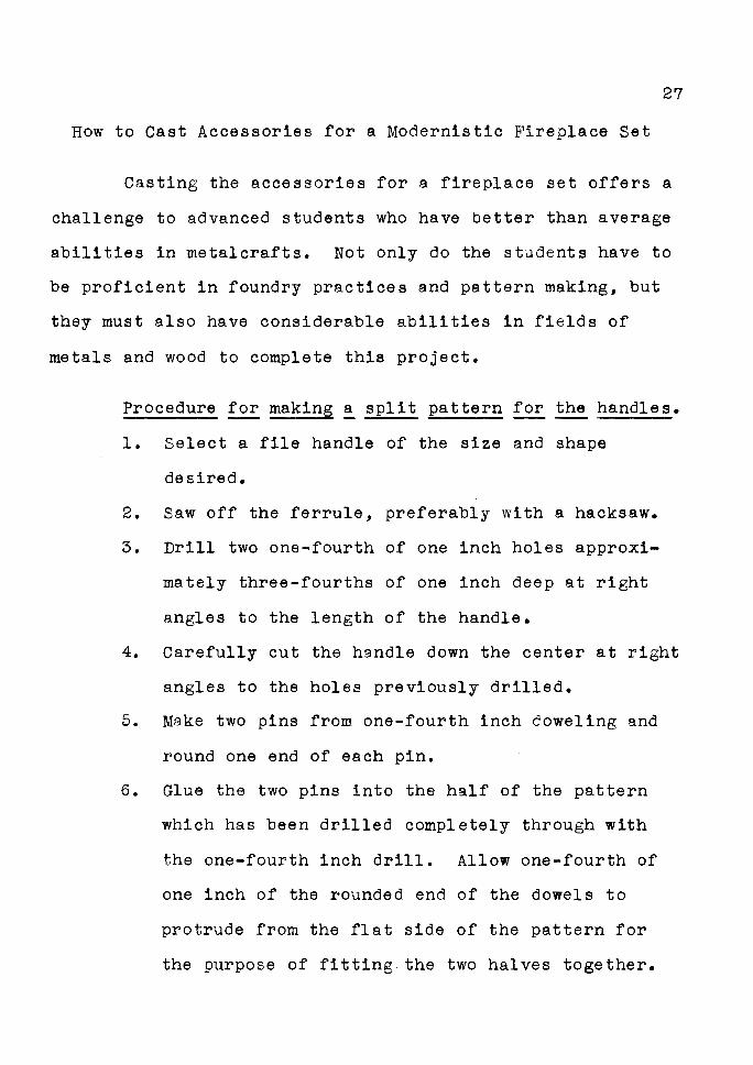
Procedure for making ~ split pattern for the handles.
1. Select a file handle of the size and shape
desired.
2. Saw off the ferrule, preferably with a hacksaw.
3. Drill two one-fourth of one inch holes approxi•
mately three-fourths of one inch deep at right
angles to the length of the handle.
4. Carefully cut the handle down the center at right
angles to the holes previously drilled.
5. Make two pins from one-fourth inch coweling and
round one end of each pin.
6. Glue the two pins into the half of the pattern
which has been drilled completely through with
the one-fourth inch drill. Allow one-fourth of
one inch of the rounded end of the dowels to
protrude from the flat side of the pattern for
the purpose of fitting.the two halves together.
set.
7. Fill all holes with putty or wood filler.
8. Smooth all surfaces with a fine grade of sand
paper or steel wool.
9. Apply two coats of shellac.
Procedure for casting the handles of the fireplace
1. Place the half of the pattern without the pins
and the drag on the molding board with the pins
of the drag in a downward position.
2. Dust the molding board and pattern thoroughly
with parting powder.
3. Riddle molding sand over the pattern to a depth
of approximately one inch.
28
4. Tuck the sand around the pattern with the fingers
into the recesses of the pattern.
5. Shovel sand into the drag until it is heaping full.
6. Ram the sand with a bench ran.mer.
7. Strike off the excess sand with a strike off bar.
8. With a vent wire, punch a series of holes in the
sand over and along the edges of the pattern. Do
not punch the holes directly to the pattern, but
approximately one-eighth of one inch away.
9. With the help of an assistant, gently turn the
molding board and the drag completely over until

the drag is facing upwards.
10. Remove the molding board.
11. With the bellows, blow all loose sand from the
drag and exposed part of the pattern.
12. Place the cope on the drag and fit the pattern
together.
29
13. Set the sprue pin approximately one-half of one
inch from one end of the pattern and the riser
pin the same distance away from the other end of
the pattern.
14. Dust parting powder on the surfaces of the
molding sand in the drag.
15. Cover the pattern to a depth of one inch or more
with riddled sand.
16. Tuck the sand into the recesses of the pattern
and around the sprue and riser pins.
17. Fill the cope heaping full with unsifted sand.
18. Repeat the same operations of ramming the cope as
was done with the drag.
19. Vent the cope as was done with the drag.
20. Remove the sprue pin and riser pin, and with a
slick, cut a pouring basin at one side of the
sprue hole.
21. Pack all loose sand around the sprue and riser
holes before lifting the cope from the drag.
22. Grasp the ears of the cope with each hand and
slowly raise the cope. Lay the cope with its
side on the foundry bench.
23. Blow off any loose sand that may be on the mold
with the bellows.
30
24. Moisten the sand next to the pattern with water.
Do not get the sand too wet; otherwise blow holes
may occur in the casting.
25. Draw the pattern from the sand.
26. Patch the mold if necessary.
27. With the gate cutter, cut the gates from the
sprue and riser holes to the mold. The gates
should be about three-eighths of one inch deep
and one-half of one inch wide.
28. Remove all loose particles of sand from the mold
with the aid of such tools as trowels, lifters,
bulb sponge or bellows.
29. Place the cope over the drag and lower into place.
30. Pour the mold with aluminum and do not disturb
for at least ten minutes.
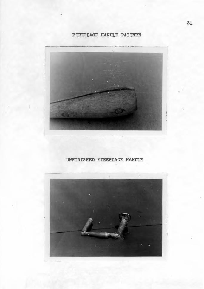
31
FIREPLACE HANDLE PATTERN
UNFINISHED FIREPLACE HANDLE
poker.
32
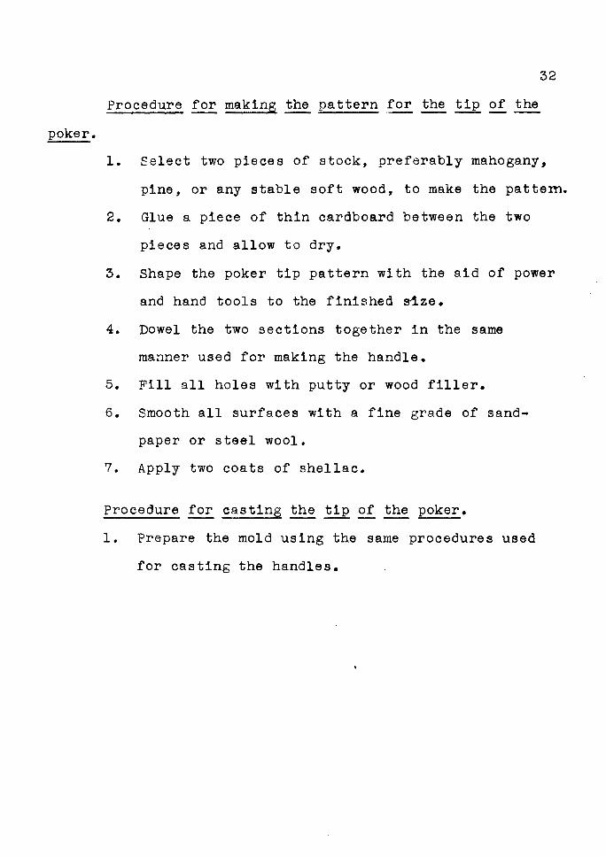
Procedure for makins the pattern for the tip of the
1. Select two pieces of stock, preferably mahogany,
pine, or any stable soft wood, to make the pattern.
2. Glue a piece of thin cardboard between the two
pieces and allow to dry.
3. Shape the poker tip pattern with the aid of power
and hand tools to the finished s1.ze.
4. Dowel the two sections together in the same
manner used for making the handle.
5. Fill all holes with putty or wood filler.
6. Smooth all surfaces with a fine grade of sand
paper or steel wool.
7. Apply two coats of shellac.
Procedure for casting the tip of the poker.
1. Prepare the mold using the same procedures used
for casting the handles.
33
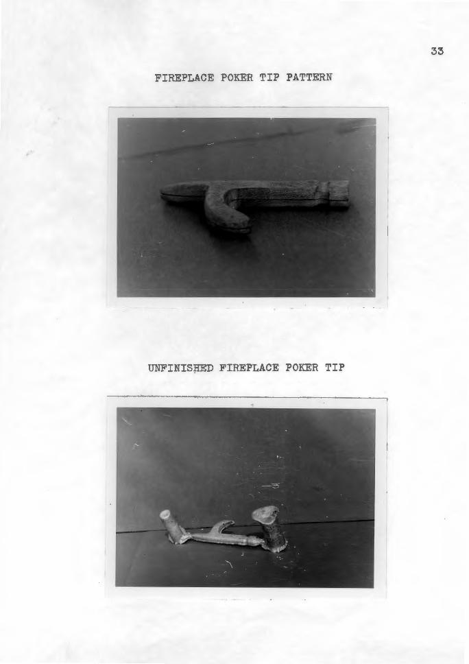
FIREPLACE POKER TIP PATTERN
UNFINISJIBD FIREPLACE POKER TIP
34
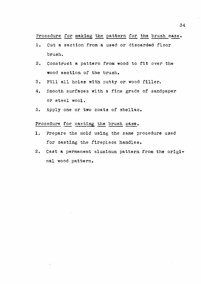
Procedure for making the pattern for the brush case.
1. Cut a section from a used or discarded floor
brush.
2. Construct a pattern from wood to fit over the
wood section of the brush.
3. Fill all holes with putty or wood filler.
4. Smooth surfaces with a fine grade of sandpaper
or steel wool.
5. Apply one or two coats of shellac.
Procedure for casting the brush ~·
1. Prepare the mold using the same procedure used
for casting the fireplace handles.
2. Cast a permanent aluminum pattern from the origi
nal wood pattern.
35
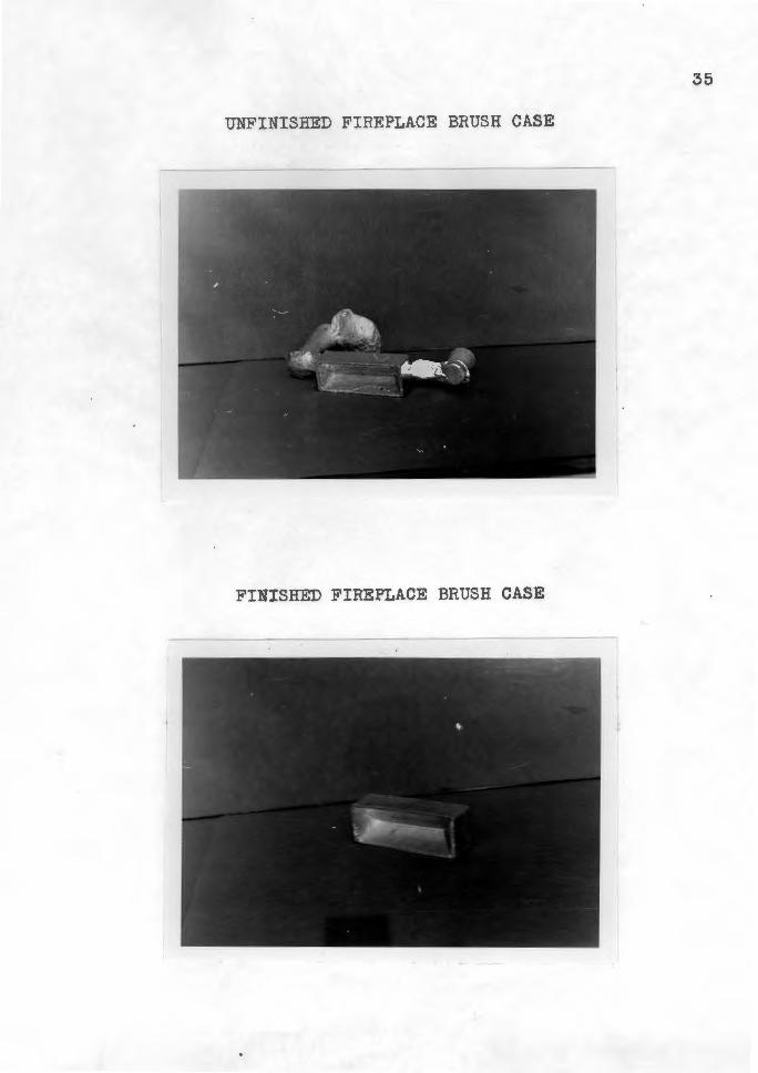
UNFINISHED FIREPLACE BRUSH CASE
FINI SHED FIREPLACE BRUSH CASE
36
FINISHED FIREPLACE SET
37
How to Cast House Numbers
An interesting and useful project which appeals to
junior high school students is an address bracket with
individual house numbers attached. variations were made by
students as to size and design of the finished project.
casting individual numbers was too slow and pain
staking a task, so a pattern was devised where all the
numbers, zero through nine, could be cast at one time.
Procedure for making the pattern.
1. Select a piece of three-quarter of one inch
plywood free from knots or blemishes.
2. Cut the board two inches longer and two inches
wider than the flask.
3. Locate and drill two holes in the plywood so the
plywood will fit over the pins of the drag.
4. Locate the house numbers in the circle on the
plywood and fasten them to the plywood with small
brads.
5. Fasten a half round knob approximately two inches
in diameter to the plywood at the center of the
circle.
6. Drill a small hole through the center of the hub
and the piece of plywood. The hole acts as a
guide for centering the sprue pin when the cope
38
part of the flask is rammed.
7. Make the gates from pieces of one-half inch split
dowel and fasten the gates from the individual
numbers to the center hub.
8. Fill all nail holes with putty or wood filler.
9. Smooth Rll surfaces with fine sandpaper or steel
wool.
10. Apply one or two coats of shellac.
Procedure for casting the house numbers.
1. Assemble the flask with the pattern board between
the cope and the drag.
2. Turn the flask with the drag on the molding board.
3. Dust the pattern board thoroughly with parting
powder.
4. Riddle sand over the pattern approximately one
inch deep.
5. Tuck the sand around the pattern with the fingers
into the recesses of the pattern.
6. Shovel sand into the flask until it is heaping
full.
7. Ram the sand with the bench rammer.
8. Strike off the excess sand with a strike off bar.
9. With the help of an assistant, gently turn the
flask completely over until the cope is facing
39
upward.
10. Dust the pattern board thoroughly with parting
powder.
11. Place the sprue pin on the mark opposite the knob.
12. Cover the pattern to a depth of one inch or more
with riddled sand.
13. Tuck the sand around the sprue pin.
14. Repeat the same operation of ramming the cope as
was done with the drag.
15. With a vent wire, punch a series of holes in the
sand over and along the edges of the pattern.
16. Do not punch the holes directly to the pattern
but approximately one-eighth of one inch away.
17. Remove the sprue pin and cut a pouring basin with
a slick at one side of the sprue hole.
18. Pack all loose sand around the sprue hole before
lifting the cope.
19. Grasp the ears of the cope with each hand and
slowly raise the cope. Lay the cope with its
side on the foundry bench.
20. Gently rag the molding board and then carefully
lift it off the drag.
21. Patch the mold i~ necessary. Trowels, lifters
and the bulb sponge are good tools to use for this
purpose.

40
22. Remove all loose particles of sand from the mold.
23. Vent each number individually. This can be
easily done by cutting a shallow groove or channel
a short distance from each number.
24. With a vent wire, punch a hole at the end of the
groove to the top surface of the cope. This is
important so each number will fill out completely
after pouring.
25. Place the cope over the drag and lower into place.
26. Pour the mold with aluminum and do not disturb
for at least fifteen minutes.
41
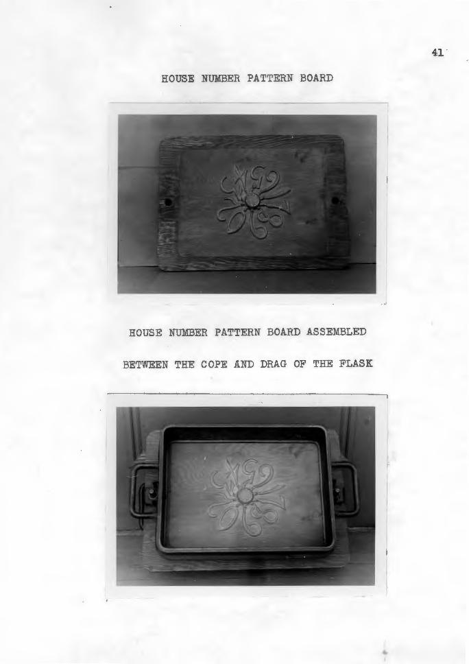
HOUSE NUMBER PATTERN BOARD
HOUSE NUMBER PATTERN BOARD ASSEMBLED
BETWEEN THE COPE AND DRAG OF THE FLASK
...
42
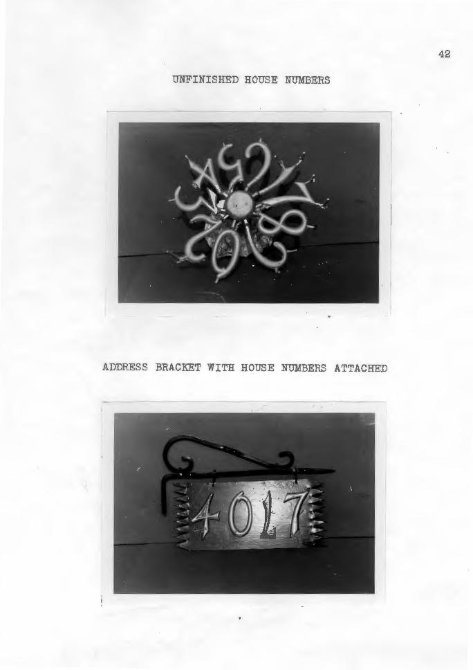
UNFINISHED HOUSE NUMBERS
ADDRESS BRACKET WITH HOUSE NUMBERS ATTACHED
43
How to Cast Cane Handles
Not only do the students make projects for themselves,
but they often participate in community work. A good ex
ample of this was the production of walking canes for dis
abled Korean veterans. These canes were made in the James
Madison Junior High School and the Garfield High School
metal shops in Seattle, Washington. The Red Cross furnished
the materials, the James Madison Junior High School cast the
handles and the Garfield High School machined the handles,
turned the cane part itself from wood and assembled the
finished product.
Approximately two hundred cane handles were cast,
and to so speed up the operation of production, a match
plate was devised to cast five cane handles simultaneously.
Procedure for making the pattern.
1. Make a split pattern from wood.
2. Cast a sufficient number of split patterns for
handles from the original pattern to make a
complete set of five split aluminum patterns.
3. File and polish to the finished size.
4. Drill one half of the pattern with a pass drill.
5. Drill the other half of the pattern with a tap
drill.
6. Tap the hole.
44
7. Cut a piece of plywood, three-fourths of one inch
thick and approximately one inch longer and wider
than the flask.
8. Arrange the halves of the patterns, which were
drilled with the pass drill, in a circle on the
plywood board.
9. Carefully mark and drill pass holes through the
plywood board.
10. Assemble the respective halves of the patterns on
each side of the plywood and secure with machine
screws of the approximate size. When assembled 1
this is called a match plate.
11. Cut off the heads of the machine screws so the
surface of the cane pattern is smooth.
12. use split three-fourths inch dowel for the gates
of the five patterns.
13. Attach the gates on each side of the match plate
but instead of using machine screws, finishing
nails and glue can be used.
14. Fill all holes with putty or wood filler.
15. Smooth all surfaces with a fine grade of sand
paper or steel wool.
16. Apply one or two coats of shellac.
17. Prepare the mold using the same procedure used
for casting the house numbers.

18. Pour the mold with aluminum and do not disturb
for at least fifteen minutes.
45
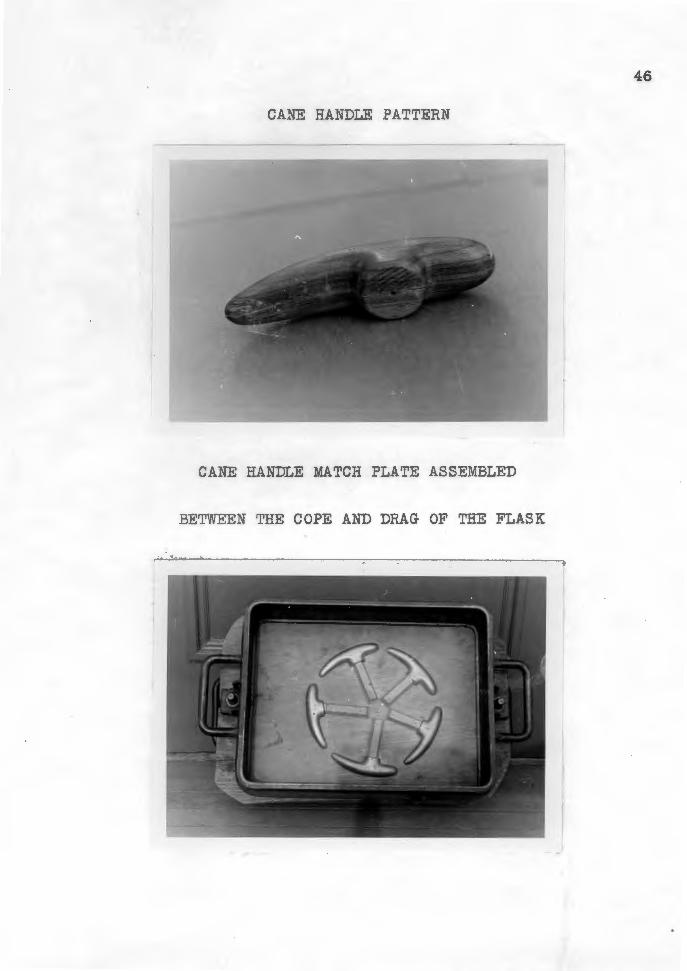
CANE HANDLE PATTERN
CANE HANDLE MATCH PLATE ASSEMBLED
BETWEEN THE COPE AND DRAG OF THE FLASK
46
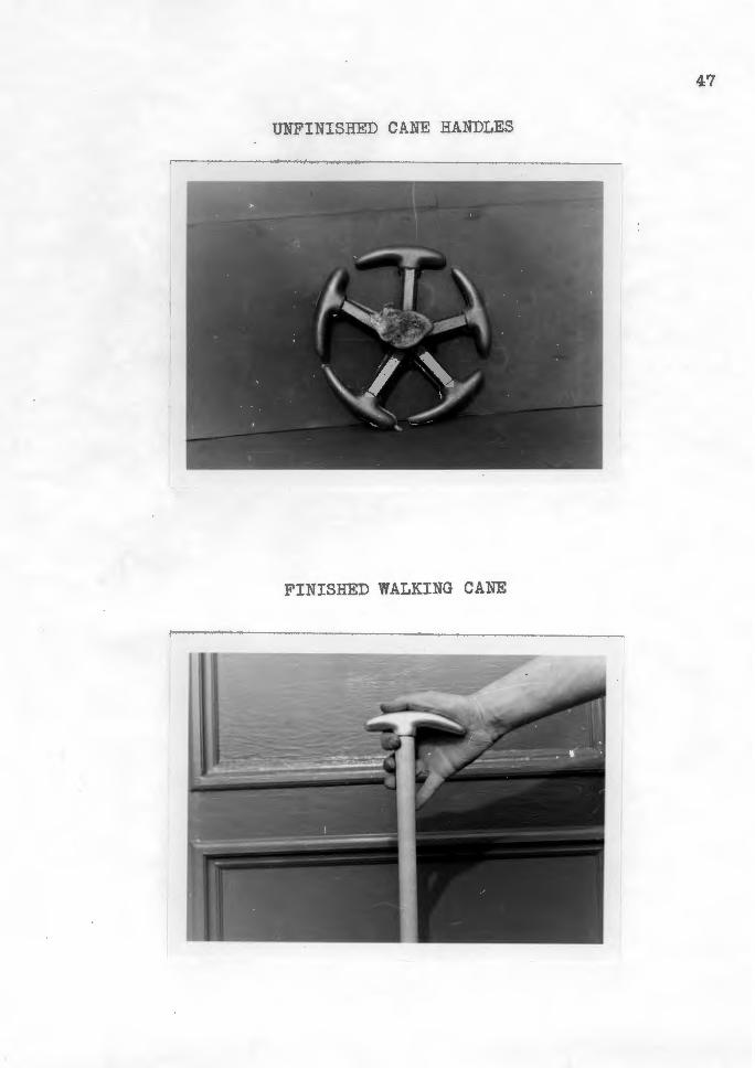
:HNVO DNI~~VM GaHSINid
sa~aNVH :HNVO aaHSINidND
CHAPTER IV
SUMMARY AND CONCLUSIONS
The topic of this study was to present some tech
niques and practices in the area of foundry to teachers in
the field of industrial arts. Step by step procedures were
used along with graphic illustrations to give the reader a
better understanding of the study.
The six projects selected for the study were tried in
actual school practices with considerable success. The
projects selected were a flower frog, book ends, a screw~
driver with a cast aluminum handle, cast accessories for a
modernistic fireplace set, aluminum house numbers and cane
handles for walking canes used by disabled veterans.
The six projects were divided into individual areas
with descriptive pictures located at the end of each project
unit.
Chapter Two was limited to related information about
foundry. The construction of patterns, characteristics of
a good molding sand, preparation and care of the molding
sand, preparation of metals for casting and other important
information was explained in detail.
Appendix A was included to give the reader a better
understanding of the technical terms used throughout the
study.

49
The projects and procedures used in the study were
from the simple to the complex, suited to meet the indi
vidual abilities of each member of the class. It should be
kept in mind, however, that the projects included in the
study were only suggestive. Teachers, as well as students,
should be constantly encouraged to develop projects and
designs of their own choosing.
It was not the purpose or intent of the writer to
stress foundry more than any other area of industrial arts.
All areas are important to meet the needs of the students
but foundry should be a definite part.


BIBLIOGRAPHY
American Foundrymen's Association: The Cast Metals Handbook, Third edition. Chicago: American Foundrymen•s Association, 1944. 745 pp.
Bacocci, Louis, "Safety in the School Foundry," Industrial Arts and Vocational Education, 40:216, May, 1951.
Crispin, Frederic and c. E. Swing, Dictionary of Technical Terms. Milwaukee: The Bruce Publishing Company, 1946. 427 pp.
Duddle, R. s., The Craft of the Metalworker. London: The Technical Press Lta.,-r9'5I:" 160 pp.
Fryklund, Verne C., Industrial Arts Teacher Education in the United States. Bloomington: McKnight and McKnight-,- ---1941. 112 pp.
Hawkings, N., and E. P. Anderson, Audels Mechanical Diction-94~· New York: Theodore Audel and Company, 1942.
pp.
Jones, Mervyn T., ttFoundry w·ork in the Junior High School," Industrial Arts and Vocational Education, 40:414, December, 19'5I':" ---
Newkirk, Louis v., General Shop for Everyone. Chicago: D. c. Heath and Company;--rg-5~ 261 pp.
Reynolds, James O., "A Demonstration Foundry Unit," Industrial Arts and Vocational Education, 40:172-3, Apri.1, 1951.
Simpson, Bruce L., Development of the Metal Castings Indus~~Y· Chicago: American Founarymenfs Association, 1948. Nb pp.
Smith, Robert E., Units in Patternmaking and Founding. Bloomington: McKnigh:r-ana McKnight PuOTishing Company, 1939. 72 pp.
Stimpson, William c., and Burton L. Gray, Foundry Work. Chicago: American Technical Society, 1940. 216 pp.
Struck, F. Theodore, Foundations of Industrial Education. New York: John Wiley and Sons-,-Inc., 1930. 492 pp.
7338;)

Wendt, R. E., Foundr~ Work. New York: McGraw-Hill Book Company, Inc., l 36. 240 pp.
Wilber, Gordon O., Industrial Arts in General Education.
52
Scranton: International Textl3'0o~Company, 1948. 36Z pp.

APPENDIX
APPENDIX A
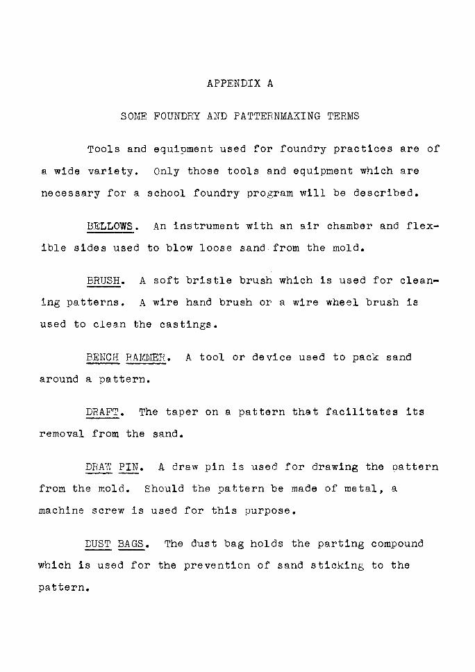
SOME FOUNDRY AND PATTERNMAKING TERMS
Tools and equipment used for foundry practices are of
a wide variety. Only those tools and equipment which are
necessary for a school foundry program will be described.
BELLOWS. An instrument with an air chamber and flex-
ible sides used to blow loose sand from the mold.
BRUSH. A soft bristle brush which is used for clean~
ing patterns. A wire hand brush or a wire wheel brush is
used to clean the castings.
BENCH RAMMER. A tool or device used to pack sand
around a pattern.
DRAFT. The taper on a pattern that facilitates its
removal from the sand.
DRAW PIN. A draw pin is used for drawing the pattern
from the mold. Should the pattern be made of metal, a
machine screw is used for this purpose.
DUST BAGS. The dust bag holds the parting compound
which is used for the prevention of sand sticking to the
pattern.
CRUCIBLE. A vessel of refractory material used for
melting purposes.
CRUCIBLE TONGS. A tool used for lifting crucibles.
55
FLASKS. A wood or metal frame used for holding sand
while a mold is made. Rectangular flasks are most commonly
used for school purposes. The bottom part of the flask is
called the drag and the top section is called the cope.
Sections may be added between the cope and drag if necessary.
These sections are called cheeks.
GATE. The passageway from the sprue hole to the
cavity of the mold.
GATE CUTTER. A gate cutter is a device used to cut a
passageway from the sprue hole to the cavity of the mold.
LIFTERS. Lifters are tools used to lift and remove
loose sand from deep passages and restricted areas of the
mold.
MATCH PLATE. A plate to which patterns are fastened
at the parting line. Used for the purpose of increasing pro
duction, especially when a large number of castings are
required.
PARTING POWDER. A manufactured compound used prima
rily to prevent two bodies of sand from sticking together.
56
PATTERN. A replica, except for size, of the object to
be cast.
RIDDLE. A device used to remove foreign matter from
sand and to deposit a fine layer of sand over the pattern.
Riddles are usually round in shape with a wire mesh bottom.
The size of the mesh is determined by the number of openings
per lineal inch. A twelve or fourteen mesh riddle is the
type recommended for average school shop practices.
RISER. An opening in the cope into which the metal
rises after the mold is filled.
SPRUE. The solidified metal left in the sprue hole
after the mold has been cast.
SPRUE HOLE. An opening in the cope where the metal
is poured and from where it runs into the mold.
SPRUE PIN. A tapered pin used for making the sprue
hole.
STRIKE OFF BAR. A steel straight edge used to scrape
the excess sand from the top of the flask.
VENT WIRE. The vent wire is used to punch holes in
the sand from the top surface of the cope to approximately
one-eighth of one inch away from the mold. These holes aid
in the escape of gases when the metal is being poured.
Related Documents