JOURNAL OF AUTOMATIC CONTROL, UNIVERSITY OF BELGRADE, VOL. 13(1):39 -46, 2003 © Some Applications of Neural Networks in Microwave Modeling Bratislav Milovanović, Vera Marković, Zlatica Marinković, Zoran Stanković Abstract –This 1 paper presents some apprilcations of neural networks in the microwave modeling. The applications are related to modeling of either passive or active structures and devices. Modeling is performed using not only simple multilayer perceptron network (MLP) but also advanced knowledge based neural network (KBNN) structures. Keywords–Neural network, modeling, microwave, microstrip gap, microwave cavity, microwave transistor, noise parameters, scattering parameters. I. INTRODUCTION Design, optimization and simulation of microwave circuits require reliable and efficient models of components and devices. The models based on the rigorous electromagnetic methods are very complex and time-consuming; and often, there is a requirement for powerful hardware platform. Sometimes, there is a lack of explicit mathematical expressions that describe the electro-magnetic nature of device. Alternatively, simple models are usually used in standard microwave circuit simulators but they have often limitations from the point of validity range and accuracy. In many of these cases, neural modeling could be a good alternative to the classical modeling. As highly nonlinear structures, neural networks are able to model nonlinear relations between different data sets, [1]. Owing to this ability, they have been applied in a wide area of problems. Especially, they are interesting for problems not fully mathematically described. Once trained they can predict response with quite a good accuracy, even for the input values not presented in the training process, without changes in their structure and without additional knowledge of considered problem. Neural models are simpler than physically based ones but retain the similar accuracy. They require less time for response providing; therefore using of neural models can make simulation and optimization processes less time-consuming, shifting much computation from on-line optimization to off-line training. Since the 1990s, neural network applications in the microwave engineering have been reported, [2]. Neural networks can be applied to the efficient modeling of microwave components, e.g., microstrip vias and interconnects [3], spiral inductors [4] and FET devices [2],[5],[6] as well as to the analysis and design of microwave circuits, e.g., microstrip circuit design, automatic microwave impedance matching and Smith chart oriented Faculty of Electronic Engineering, University of Niš, Beogradska 14, PO Box 73, 18000 Niš, Yugoslavia Phone: +381 18 529 303, Fax: +381 18 524 931 E-Mail: [bata,vera,zlatica,zoran]@elfak.ni.ac.yu microwave circuit analysis and design [7]. Neural network modeling has also been applied to circuit optimization and statistical design, e.g., signal integrity analysis and optimization of very large-scale integrated circuit (VLSI) interconnects [8],[9], microwave circuit optimization and statistical design with neural network models at either device or circuit levels [10]. Besides, encouraging results have been obtained using neural network modeling in the areas of antenna modeling (neural network based beam- forming,[11], neural network implementation of direction of arrival estimation problem,[12]) and radar technique (neural network for a radar signal characterization and automatic target recognition, [13]-[15]). During last five years, the authors of the paper have been worked on neural network applications in the microwave circuits modeling. Neural networks are applied to the resonant cavity applicator modeling, [16]-[24] as well as to microwave MESFET and HEMT transistor modeling, [25]- [33]. Also, the first steps in microwave discontinuities modeling using neural networks have been made [34]-[36]. This paper addresses to the achieved results. Neural network training, testing and simulation are performed in MATLAB software package environment. Mostly, a multi layer perceptron network (MLP) is implemented. Advanced neural structures based on existing knowledge are proposed and applied as well. II. MICROWAVE CAVITY MODELING Microwave applicators are used thermal dielectric material processing in industry, science and medicine. In the most cases these applicators have form of the cylindrical metallic cavities with various cross-sections (rectangular, circular, elliptical, etc). Spatially application in processes of dielectric material heating has the cavities loaded by plan- parallel homogeneous dielectric slabs. The knowledge of the mode tuning behavior as well as some other electrical parameters under loading condition has important significance. Usually, a theoretical analysis of the cylindrical metallic cavities is based on the application of the transversal resonance method [16]. The resonant frequencies are determined from the characteristic equation, which is real transcendental for lossless dielectric slabs and complex transcendental for any lossy dielectric slab. An approximate numerical technique for resonant frequency determination and an efficient procedure for mode identification (especially in the case of a multilayer lossy load) are proposed, [17]. In order to avoid complex and time- consuming mathematical calculations authors have

Welcome message from author
This document is posted to help you gain knowledge. Please leave a comment to let me know what you think about it! Share it to your friends and learn new things together.
Transcript

JOURNAL OF AUTOMATIC CONTROL, UNIVERSITY OF BELGRADE, VOL. 13(1):39 -46, 2003 ©
Some Applications of Neural Networks in Microwave Modeling
Bratislav Milovanović, Vera Marković, Zlatica Marinković, Zoran Stanković
Abstract –This1 paper presents some apprilcations of neural
networks in the microwave modeling. The applications are related to modeling of either passive or active structures and devices. Modeling is performed using not only simple multilayer perceptron network (MLP) but also advanced knowledge based neural network (KBNN) structures.
Keywords–Neural network, modeling, microwave, microstrip gap, microwave cavity, microwave transistor, noise parameters, scattering parameters.
I. INTRODUCTION
Design, optimization and simulation of microwave circuits require reliable and efficient models of components and devices. The models based on the rigorous electromagnetic methods are very complex and time-consuming; and often, there is a requirement for powerful hardware platform. Sometimes, there is a lack of explicit mathematical expressions that describe the electro-magnetic nature of device. Alternatively, simple models are usually used in standard microwave circuit simulators but they have often limitations from the point of validity range and accuracy.
In many of these cases, neural modeling could be a good alternative to the classical modeling. As highly nonlinear structures, neural networks are able to model nonlinear relations between different data sets, [1]. Owing to this ability, they have been applied in a wide area of problems. Especially, they are interesting for problems not fully mathematically described. Once trained they can predict response with quite a good accuracy, even for the input values not presented in the training process, without changes in their structure and without additional knowledge of considered problem. Neural models are simpler than physically based ones but retain the similar accuracy. They require less time for response providing; therefore using of neural models can make simulation and optimization processes less time-consuming, shifting much computation from on-line optimization to off-line training.
Since the 1990s, neural network applications in the microwave engineering have been reported, [2]. Neural networks can be applied to the efficient modeling of microwave components, e.g., microstrip vias and interconnects [3], spiral inductors [4] and FET devices [2],[5],[6] as well as to the analysis and design of microwave circuits, e.g., microstrip circuit design, automatic microwave impedance matching and Smith chart oriented
Faculty of Electronic Engineering, University of Niš, Beogradska 14, PO Box 73, 18000 Niš, Yugoslavia Phone: +381 18 529 303, Fax: +381 18 524 931 E-Mail: [bata,vera,zlatica,zoran]@elfak.ni.ac.yu
microwave circuit analysis and design [7]. Neural network modeling has also been applied to circuit optimization and statistical design, e.g., signal integrity analysis and optimization of very large-scale integrated circuit (VLSI) interconnects [8],[9], microwave circuit optimization and statistical design with neural network models at either device or circuit levels [10]. Besides, encouraging results have been obtained using neural network modeling in the areas of antenna modeling (neural network based beam-forming,[11], neural network implementation of direction of arrival estimation problem,[12]) and radar technique (neural network for a radar signal characterization and automatic target recognition, [13]-[15]).
During last five years, the authors of the paper have been worked on neural network applications in the microwave circuits modeling. Neural networks are applied to the resonant cavity applicator modeling, [16]-[24] as well as to microwave MESFET and HEMT transistor modeling, [25]-[33]. Also, the first steps in microwave discontinuities modeling using neural networks have been made [34]-[36]. This paper addresses to the achieved results.
Neural network training, testing and simulation are performed in MATLAB software package environment. Mostly, a multi layer perceptron network (MLP) is implemented. Advanced neural structures based on existing knowledge are proposed and applied as well.
II. MICROWAVE CAVITY MODELING
Microwave applicators are used thermal dielectric material processing in industry, science and medicine. In the most cases these applicators have form of the cylindrical metallic cavities with various cross-sections (rectangular, circular, elliptical, etc). Spatially application in processes of dielectric material heating has the cavities loaded by plan-parallel homogeneous dielectric slabs. The knowledge of the mode tuning behavior as well as some other electrical parameters under loading condition has important significance.
Usually, a theoretical analysis of the cylindrical metallic cavities is based on the application of the transversal resonance method [16]. The resonant frequencies are determined from the characteristic equation, which is real transcendental for lossless dielectric slabs and complex transcendental for any lossy dielectric slab. An approximate numerical technique for resonant frequency determination and an efficient procedure for mode identification (especially in the case of a multilayer lossy load) are proposed, [17]. In order to avoid complex and time-consuming mathematical calculations authors have
40 MILOVANOVIĆ, B., ET AL. SOME APPLICATIONS OF NEURAL NETWORKS IN MICROWAVE MODELING
suggested an application of neural networks in resonant frequency determination, [18]-[24].
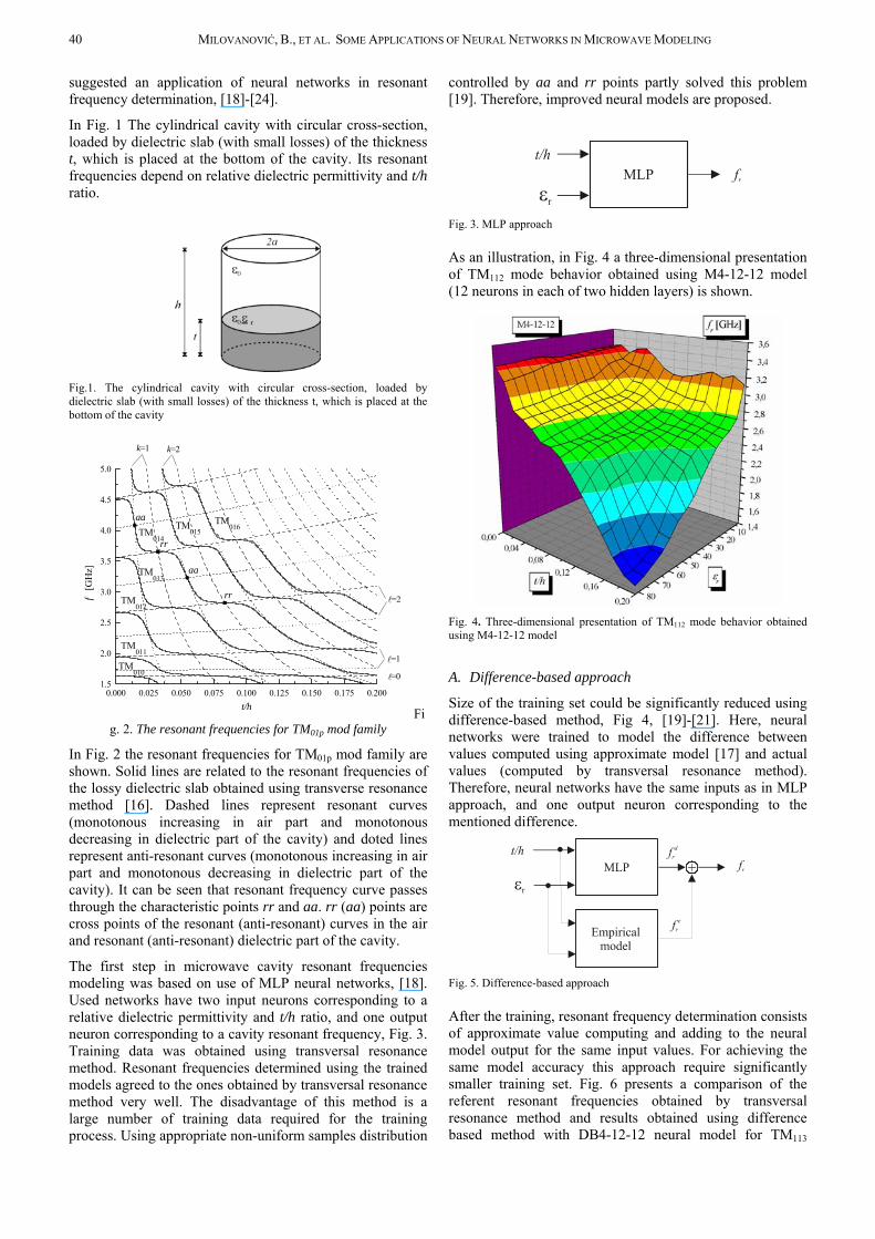
In Fig. 1 The cylindrical cavity with circular cross-section, loaded by dielectric slab (with small losses) of the thickness t, which is placed at the bottom of the cavity. Its resonant frequencies depend on relative dielectric permittivity and t/h ratio.
Fig.1. The cylindrical cavity with circular cross-section, loaded by dielectric slab (with small losses) of the thickness t, which is placed at the bottom of the cavity
0.000 0.025 0.050 0.075 0.100 0.125 0.150 0.175 0.2001.5
2.0
2.5
3.0
3.5
4.0
4.5
5.0
l
l
l
=2
=1
=0
k=2k=1
TM016
rr
rr
aa
aaTM
015TM014
TM013
TM012
TM011
TM010
f [G
Hz]
t/h Fig. 2. The resonant frequencies for TM01p mod family
In Fig. 2 the resonant frequencies for TM01p mod family are shown. Solid lines are related to the resonant frequencies of the lossy dielectric slab obtained using transverse resonance method [16]. Dashed lines represent resonant curves (monotonous increasing in air part and monotonous decreasing in dielectric part of the cavity) and doted lines represent anti-resonant curves (monotonous increasing in air part and monotonous decreasing in dielectric part of the cavity). It can be seen that resonant frequency curve passes through the characteristic points rr and aa. rr (aa) points are cross points of the resonant (anti-resonant) curves in the air and resonant (anti-resonant) dielectric part of the cavity.
The first step in microwave cavity resonant frequencies modeling was based on use of MLP neural networks, [18]. Used networks have two input neurons corresponding to a relative dielectric permittivity and t/h ratio, and one output neuron corresponding to a cavity resonant frequency, Fig. 3. Training data was obtained using transversal resonance method. Resonant frequencies determined using the trained models agreed to the ones obtained by transversal resonance method very well. The disadvantage of this method is a large number of training data required for the training process. Using appropriate non-uniform samples distribution
controlled by aa and rr points partly solved this problem [19]. Therefore, improved neural models are proposed.
Fig. 3. MLP approach
As an illustration, in Fig. 4 a three-dimensional presentation of TM112 mode behavior obtained using M4-12-12 model (12 neurons in each of two hidden layers) is shown.
Fig. 4. Three-dimensional presentation of TM112 mode behavior obtained using M4-12-12 model
A. Difference-based approach
Size of the training set could be significantly reduced using difference-based method, Fig 4, [19]-[21]. Here, neural networks were trained to model the difference between values computed using approximate model [17] and actual values (computed by transversal resonance method). Therefore, neural networks have the same inputs as in MLP approach, and one output neuron corresponding to the mentioned difference.
Fig. 5. Difference-based approach
After the training, resonant frequency determination consists of approximate value computing and adding to the neural model output for the same input values. For achieving the same model accuracy this approach require significantly smaller training set. Fig. 6 presents a comparison of the referent resonant frequencies obtained by transversal resonance method and results obtained using difference based method with DB4-12-12 neural model for TM113

JOURNAL OF AUTOMATIC CONTROL, UNIVERSITY OF BELGRADE 41
mode. DB4-12-12 model is trained on the training set of only 174 samples.
0.00 0.02 0.04 0.06 0.08 0.102.6 2.8 3.0 3.2 3.4 3.6 3.8 4.0 4.2 TM 113
Referent curve DB4-12-12
εr=80
εr=45
εr=8.1
εr=3.5
t/h
[GHz]
fr
Fig. 6. Comparison of the referent results and results for DB4-12-12 neural model for TM113 mode
B. Hybrid empirical neural approach
Hybrid empirical neural (HEN) approach is alternatively way to reducing of size of the training set could be significantly reduced, Fig 7, [22]. MLP neural networks are trained to model cavity resonant frequencies.
This MLP network has one input more than one in classical MLP approach. Namely, resonant frequency was computed using existing empirical model and this approximate values were lead to the network inputs. Training values for resonant frequency were computed by transversal resonance method. Figure R8 shows three-dimensional presentation of TM112 mode behavior obtained using H4-12-10 model (12 neurons in the firs and 10 neurons in the second hidden layer , observed from the input to the output).
Fig. 6. Hybrid empirical neural approach
Fig. 7. Three-dimensional presentation of TM112 mode behavior obtained using H4-12-10 model
C. Knowledge-based neural approach
The newest results in microwave resonant cavity modeling are addressed to the application of the knowledge based neural network (KBNN) structure, [23]-[24]. Since, there are explicate expressions for the resonant and anti resonant curves dependence on rε and t/h (shown in Fig. 2) [17], the basic idea for KBBN approach is implementation of this expressions as activation functions of some neurons in the neural network. In Figure 9, proposed KBNN architecture is presented.
KBNN structure is a modified MLP structure. Namely, a network is consists of neurons grouped into the layers. Beside layers of sigmoid neurons, there are so-called knowledge neurons. Activation functions are modified existing expressions of the resonant and anti-resonant curves.
Application of such structure leads to a increasing of network generalization capabilities yielding to a further reducing of required number of training samples. Furthermore, this approach eliminates need for the use of empirical model used in HEN approach making resonant frequency determination faster.
Fig. 9. Knowledge based neural network
In Figure 10 a three-dimensional presentation of TM112 mode obtained using KBNN3-4-16-16-16 model. This model has three sigmoid hidden layers (16 neurons in each layer), and four knowledge neurons. Training set consists of 80 samples.

42 MILOVANOVIĆ, B., ET AL. SOME APPLICATIONS OF NEURAL NETWORKS IN MICROWAVE MODELING
Fig. 10. Three-dimensional presentation of TM112 mode obtained using KBNN3-4-16-16-16 model
III. MICROWAVE TRANSISTOR MODELING
Microwave transistors are used in many microwave active circuits. Circuit design process requires reliable and efficient models of the microwave transistors. Most of the existing models refer to one bias point, and for any other bias point it is necessary to recalculate elements and/or parameters of the model. Neural network approach to the transistor modeling provides models valid in the whole operating range of biases, [25]-[33]. Microwave characteristics of transistors can be described by transistor scattering and noise parameters [33].
A. Modeling of transistor scattering parameters
In [25] neural modeling of HEMT/MESFET transistors’ scattering parameters are proposed. A standard MLP neural network is used for modeling dependence of S-parameters on biases and frequency, Fig 11. Therefore, three neural network input neurons corresponding to:
• dc drain-to-source voltage, • dc drain-to-source current and • frequency.
The network has eight outputs corresponding to the magnitudes and angles of four S-parameters.
NNet ) A n g ( 1 2 S ) M a g ( 1 2 S ) A n g ( 1 1 S ) M a g ( 1 1 S
) A n g ( 2 1 S ) M a g ( 2 1 S
) A n g ( 2 2 S ) M a g ( 2 2 S
d s V d s I f
] [ S
Fig. 11. S-parameters modeling
Training data was taken from the manufacturer Web site. The obtained neural models have an excellent prediction of the S-parameters not only for the biases used for the training but also for the biases completely different from the training
ones. Also, it should be noted that after training of the networks, prediction of S-parameters does not requires network parameter changes.
As an illustration, Fig. 12 shows prediction of parameter for a bias not used for the training. The black dots represent measured (reference values) and solid line with empty circles neural model output. A notation sp_10_10 represent neural network modeling s-parameters with ten neurons in each of two hidden layers.
11S
B. Modeling of transistor noise
Transistor noise is described by the four noise parameters (minimum noise figure , normalized equivalent noise resistance , and magnitude and angle of optimum reflection coefficient
minF
nr
optΓ ), [33].
The first steps in neural network approach in transistor noise modeling were so-called “bf”-approach (biases & frequency), [26]. Noise parameters dependence on biases and frequency was modeled using MLP networks with two hidden layers, Fig. 13.
0,5
1,0
0
30
60
90
120
150
180
210
240
270
300
330
0,5
1,0
S11
reference valuessp_10_10 output
Fig. 12. S-parameters modeling
dsV
dsI
f
minF)(Mag optΓ
)(Ang optΓ
nr
NNet
Fig. 13. Neural model of noise parameters’ dependence on bias conditions and frequency (bf approach)
Networks have three neural network input neurons corresponding to:
• dc drain-to-source voltage, • dc drain-to-source current and • frequency.
Output layer consists of four neurons corresponding to four noise parameters.
JOURNAL OF AUTOMATIC CONTROL, UNIVERSITY OF BELGRADE 43
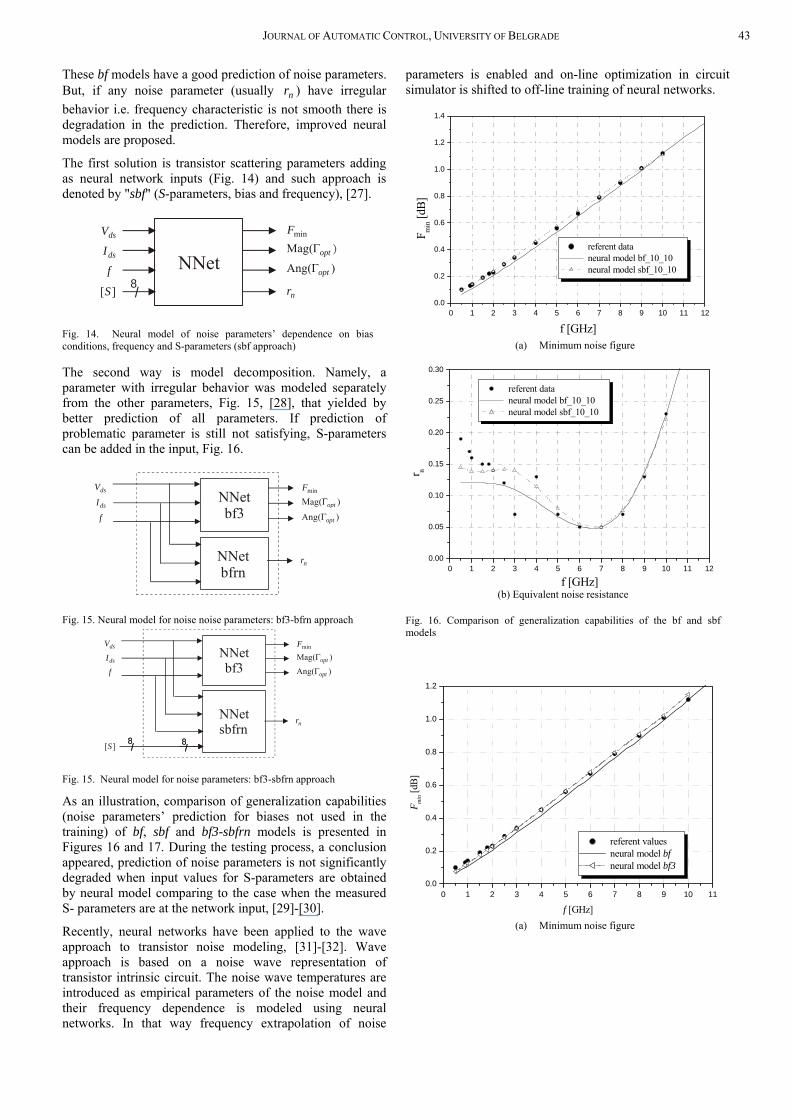
These bf models have a good prediction of noise parameters. But, if any noise parameter (usually ) have irregular behavior i.e. frequency characteristic is not smooth there is degradation in the prediction. Therefore, improved neural models are proposed.
nr
The first solution is transistor scattering parameters adding as neural network inputs (Fig. 14) and such approach is denoted by "sbf" (S-parameters, bias and frequency), [27].
dsV
dsI
f
minF)(Mag optΓ
)(Ang optΓ
nr
NNet][S /8
Fig. 14. Neural model of noise parameters’ dependence on bias conditions, frequency and S-parameters (sbf approach)
The second way is model decomposition. Namely, a parameter with irregular behavior was modeled separately from the other parameters, Fig. 15, [28], that yielded by better prediction of all parameters. If prediction of problematic parameter is still not satisfying, S-parameters can be added in the input, Fig. 16.
nrNNetbfrn
dsV
dsI
f
minF)(Mag optΓ
)(Ang optΓ
NNetbf3
Fig. 15. Neural model for noise noise parameters: bf3-bfrn approach
nrNNetsbfrn
][S /8/
8
dsV
dsI
f
minF)(Mag optΓ
)(Ang optΓ
NNetbf3
/8/
8
Fig. 15. Neural model for noise parameters: bf3-sbfrn approach
As an illustration, comparison of generalization capabilities (noise parameters’ prediction for biases not used in the training) of bf, sbf and bf3-sbfrn models is presented in Figures 16 and 17. During the testing process, a conclusion appeared, prediction of noise parameters is not significantly degraded when input values for S-parameters are obtained by neural model comparing to the case when the measured S- parameters are at the network input, [29]-[30].
Recently, neural networks have been applied to the wave approach to transistor noise modeling, [31]-[32]. Wave approach is based on a noise wave representation of transistor intrinsic circuit. The noise wave temperatures are introduced as empirical parameters of the noise model and their frequency dependence is modeled using neural networks. In that way frequency extrapolation of noise
parameters is enabled and on-line optimization in circuit simulator is shifted to off-line training of neural networks.
0 1 2 3 4 5 6 7 8 9 10 11 120.0
0.2
0.4
0.6
0.8
1.0
1.2
1.4
F min [d
B]
f [GHz]
referent data neural model bf_10_10 neural model sbf_10_10
(a) Minimum noise figure
0 1 2 3 4 5 6 7 8 9 10 11 10.00
0.05
0.10
0.15
0.20
0.25
0.30
2
r n
f [GHz]
referent data neural model bf_10_10 neural model sbf_10_10
(b) Equivalent noise resistance
Fig. 16. Comparison of generalization capabilities of the bf and sbf models
0 1 2 3 4 5 6 7 8 9 10 10.0
0.2
0.4
0.6
0.8
1.0
1.2
1
F min [d
B]
f [GHz]
referent values neural model bf neural model bf3
(a) Minimum noise figure
44 MILOVANOVIĆ, B., ET AL. SOME APPLICATIONS OF NEURAL NETWORKS IN MICROWAVE MODELING
0 1 2 3 4 5 6 7 8 9 10 10.00
0.05
0.10
0.15
0.20
0.25
0.30
1
r n
f [GHz]
referent values neural model bf neural model bfrn neural model sbfrn
(b) Equivalent noise resistance
Fig. 17. Comparison of generalization capabilities of the bf and bf3-sbfrn models
IV. MICROSTRIP ELEMENT MODELING
In order to avoid a solving of a number of time-consuming complex electromagnetic equations needed for the analysis and optimization of microstrip circuits, a new approach using neural models of microstrip elements has been proposed. The neural modeling of microstrip elements is presented through a microstrip gap scattering parameter modelling, [34].
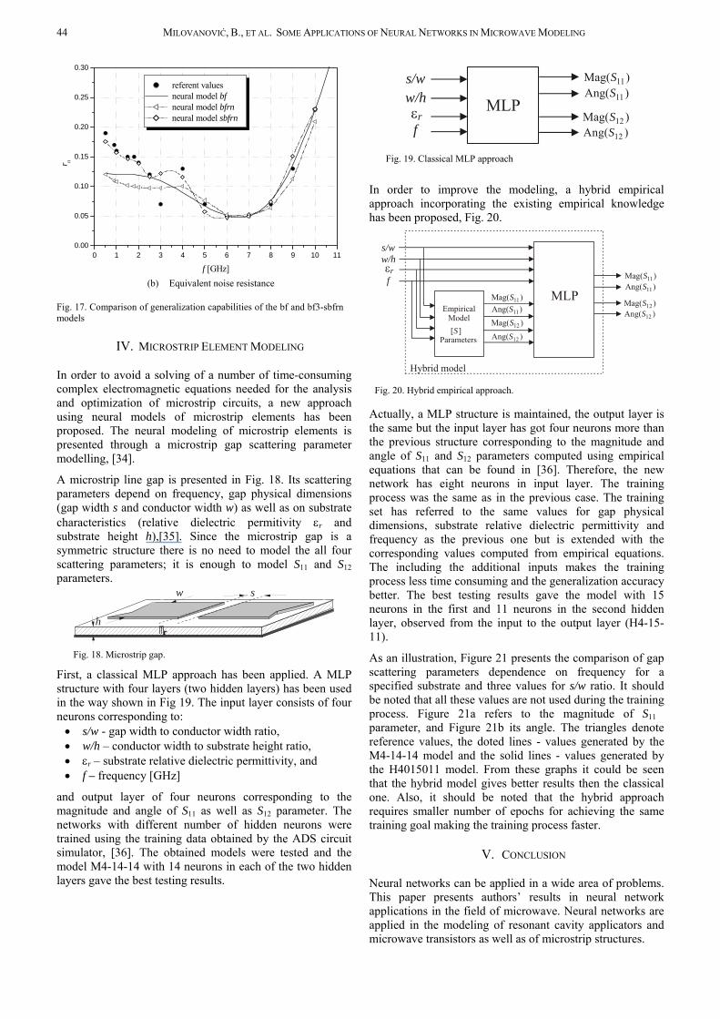
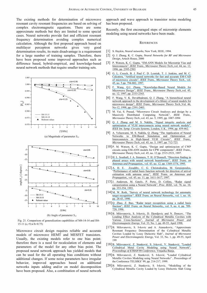
A microstrip line gap is presented in Fig. 18. Its scattering parameters depend on frequency, gap physical dimensions (gap width s and conductor width w) as well as on substrate characteristics (relative dielectric permitivity εr and substrate height h),[35]. Since the microstrip gap is a symmetric structure there is no need to model the all four scattering parameters; it is enough to model S11 and S12 parameters.
s
h
w
r
Fig. 18. Microstrip gap.
First, a classical MLP approach has been applied. A MLP structure with four layers (two hidden layers) has been used in the way shown in Fig 19. The input layer consists of four neurons corresponding to: • s/w - gap width to conductor width ratio, • w/h – conductor width to substrate height ratio, • εr – substrate relative dielectric permittivity, and • f – frequency [GHz]
and output layer of four neurons corresponding to the magnitude and angle of S11 as well as S12 parameter. The networks with different number of hidden neurons were trained using the training data obtained by the ADS circuit simulator, [36]. The obtained models were tested and the model M4-14-14 with 14 neurons in each of the two hidden layers gave the best testing results.
MLP)Ang( 12S)Mag( 12S
)Ang( 11S)Mag( 11Ss/w
w/h
fεr
Fig. 19. Classical MLP approach
In order to improve the modeling, a hybrid empirical approach incorporating the existing empirical knowledge has been proposed, Fig. 20.
Empirical Model
MLP
][SParameters )Ang( 12S
)Mag( 12S)Ang( 11S)Mag( 11S
s/ww/h
f
)Ang( 12S)Mag( 12S
)Ang( 11S)Mag( 11S
Hybrid model
εr
Fig. 20. Hybrid empirical approach.
Actually, a MLP structure is maintained, the output layer is the same but the input layer has got four neurons more than the previous structure corresponding to the magnitude and angle of S11 and S12 parameters computed using empirical equations that can be found in [36]. Therefore, the new network has eight neurons in input layer. The training process was the same as in the previous case. The training set has referred to the same values for gap physical dimensions, substrate relative dielectric permittivity and frequency as the previous one but is extended with the corresponding values computed from empirical equations. The including the additional inputs makes the training process less time consuming and the generalization accuracy better. The best testing results gave the model with 15 neurons in the first and 11 neurons in the second hidden layer, observed from the input to the output layer (H4-15-11).
As an illustration, Figure 21 presents the comparison of gap scattering parameters dependence on frequency for a specified substrate and three values for s/w ratio. It should be noted that all these values are not used during the training process. Figure 21a refers to the magnitude of S11 parameter, and Figure 21b its angle. The triangles denote reference values, the doted lines - values generated by the M4-14-14 model and the solid lines - values generated by the H4015011 model. From these graphs it could be seen that the hybrid model gives better results then the classical one. Also, it should be noted that the hybrid approach requires smaller number of epochs for achieving the same training goal making the training process faster.
V. CONCLUSION
Neural networks can be applied in a wide area of problems. This paper presents authors’ results in neural network applications in the field of microwave. Neural networks are applied in the modeling of resonant cavity applicators and microwave transistors as well as of microstrip structures.
JOURNAL OF AUTOMATIC CONTROL, UNIVERSITY OF BELGRADE 45
The existing methods for determination of microwave resonant cavity resonant frequencies are based on solving of complex electromagnetic equations. There are some approximate methods but they are limited to some special cases. Neural networks provide fast and efficient resonant frequency determination avoiding complex numerical calculation. Although the first proposed approach based on multilayer perceptron networks gives very good determination results, its main disadvantage is a requirement for a large number of training samples. Therefore, there have been proposed some improved approaches such as difference based, hybrid-empirical, and knowledge-based neural network methods that require smaller training sets.
1 2 3 4 5 6 7 8 9 10.970
0.975
0.980
0.985
0.990
0.995
1.000
1.005
0
s/w=0.95
s/w=0.55
s/w=0.15
H4-15-11 M4-14-14 Referent values
|S11
|
f [GHz] (a) Magnitude of parameter S11
1 2 3 4 5 6 7 8 9
-15
-10
-5
10
s/w=0.95
s/w=0.15
s/w=0.55
angl
e(S 11
) [ d
egre
es ]
f [GHz]
H4-15-11 M4-14-14 Referent values
1 2 3 4 5 6 7 8 9
-15
-10
-5
10
1 2 3 4 5 6 7 8 9
-15
-10
-5
10
(b) Angle of parameter S11
Fig. 21. Comparison of generalization capabilities of M4-14-14 and H4-15-11 (εr=9,w/h=0.75)
Microwave circuit design requires reliable and accurate models of microwave HEMT and MESFET transistors. Usually, the existing models refer to one bias point; therefore there is a need for recalculation of elements and parameters of the model for any other bias point. The proposed neural network approach has yielded models that can be used for the all operating bias conditions without additional changes. If some noise parameters have irregular behavior, improved approaches based on additional networks inputs adding and/or on model decomposition have been proposed. Also, a combination of neural network
approach and wave approach to transistor noise modeling has been proposed.
Recently, the first encouraged steps of microstrip elements modeling using neural networks have been made.
REFERENCES
[1] S. Haykin, Neural networks, New York, IEEE, 1994. [2] Q. J. Zhang, K. C. Gupta, Neural Networks for RF and Microwave
Design, Artech House, 2000 [3] P. Watson, K. C. Gupta, “EM-ANN Models for Microstrip Vias and
Interconnects”, IEEE Trans., Microwave Theory Tech.,vol. 44, no. 12, 1996, pp. 2395-2503
[4] G. L. Creech, B. J. Paul C. D. Lesniak, T. J. Jenkins, and M. C. Calcatera, “Artifical neural networks for fast and accurate EM-CAD of microwave circuits”, IEEE Trans., Microwave Theory Tech., vol. 45, no. 5 pp. 794-802, 1997.
[5] F. Wang, Q.J. Zhang, “Knowledge-Based Neural Models for Microwave Design”, IEEE Trans., Microwave Theory Tech.,vol. 45, no. 12, 1997, pp. 2333-2343.
[6] F. Wang, V. K. Devabhaktuni, Q. J. Zhang, “A hierarchical neural network approach to the development of a library of neural models for microwave design”, IEEE Trans., Microwave Theory Tech.,Vol. 46, No-12, 1998, pp.-2391-2403.
[7] M. Vai, S. Prasad, “Microwave Circuit Analysys and design by a Massively Distributed Computing Network”, IEEE Trans., Microwave Theory Tech.,vol. 43, no. 5, 1995, pp. 1087-1094
[8] Q. J. Zhang and M. S. Nakhla, “Signal integrity analysis and optimization of VLSI interconnects using neural network models”, IEEE Int. Symp. Circuits Systems, London, U.K., 1994, pp. 459-462.
[9] A. Veluswami, M. S. Nakhla, Q. Zhang “The Application of Neural Networks to EM-Based Simulation and Optimization of Interconnetcts in High-Speed VLSI Circuits”, IEEE Trans., Microwave Theory Tech.,vol. 45, no. 5, 1997, pp. 712-723.
[10] P. M. Watson, K. C. Gupta, “Design and optimizacion of CWP circuits using EM-ANN models for CPW components”, IEEE Trans., Microwave Theory Tech.,vol. 45, no. 12 pp. 2515-2523, 1997.
[11] H. L. Southall, J. A. Simmers, T. H. O’Donnell, “Direction finding in phased arrays with neural network beamformer”, IEEE Trans. on Antennas and Propagation,, vol. 43, no. 12, pp. 1369-1374, 1995.
[12] A. H. E. Zooghby, C. G. Christodoulou, M. Gergiopoulos, “Performance of radial basis function network for direction of arrival estimation with antenna array”, IEEE Trans. on Antennas and Propagation,, vol. 45, no. 11, pp. 1611-1617, 1997.
[13] J. Anderson, M. Gately, P. Pertz, D. Collins, “Radar signal categorization using a Neural Network”, Proc. IEEE, vol. 78, no. 10, pp. 353-354, 1993.
[14] M. W. Roth, “Survey of neural network technology for automatic target recognition”, IEEE Trans. on Neural Networks,, vol. 1, no. 10, pp. 28-43, 1990.
[15] Q. Zhao, Z. Bao, “Radar target recognition using a radial basis finction”, IEEE Trans. on Neural Networks,, vol. 9, no. 4, pp. 709-720, 1996.
[16] B. Milovanovic, S. Ivkovic, D. Djordjevic and N. Doncov, “The Loading Effect Analysis of the Cylindrical Metallic Cavities with Various Cross-Sections”, Journal of Microwave Power and Electromagnetic Energy, Vol. 33, No. 1, pp. 49-55, April 1998.
[17] B. Milovanovic, S. Ivkovic and A. Atanaskovic, “Approximate Resonant Frequency Determination of the Cylindrical Metallic Cavities Loaded by Lossy Dielectric Slab”, Journal of Microwave Power and Electromagnetic Energy, Vol. 33, No. 1, pp. 49-55, April 199
[18] B. Milovanović, Z. Stanković, S. Ivković, V. Stanković, "Loaded Cylindrical Metal Cavity Modeling using Neural Network", Proceedings of ETRAN'99 Conference, Vrnjačka Banja.
[19] B. Milovanović, Z. Stanković, S. Ivković, "Loaded Cylindrical Metallic Cavities Modeling using Neural Networks” , Proceedings of the Conference TELSIKS’ 99, pp. 214-217, 1999.
[20] B. Milovanović, Z. Stankovic, S. Ivkovic, “Modelling of the Cylindrical Metallic Cavity Loaded by Lossy Dielectric Slab Using
46 MILOVANOVIĆ, B., ET AL. SOME APPLICATIONS OF NEURAL NETWORKS IN MICROWAVE MODELING
Neural Networks”, Proceedings of the Conference NEUREL 2000, Beograd, Septembar 2000, pp. 141-145.
[21] B. Milovanovic, Z. Stankovic, S. Ivkovic, “Modelling of the Cylindrical Metallic Cavity with Circular Cross-section using Neural Networks”, MELECON’2000 Conference Proceedings, Vol.II, Cyprus 2000, pp. 449-452.
[22] B. Milovanović, Z. Stanković, “Microwave Cylindrical Cavity Applicators Modeling using Hybrid Empirical Neural Model”, International Conference “Modern Problems of Radio Engineering, Telecommunications and Computer Science”, Proceedings of the Conference TCSET 2002, 18-23 February, 2002, Lviv-Slavsko, Ukraine.
[23] Z. Stankovic, B. Milovanovic and S. Ivkovic, “Microwave Cylindrical Cavity Applicators Modeling Using Knowledge Based Neural Networks”, IEEE TELSIKS 2001 Conference Proceedings, Nis, Yugoslavia, pp. 687-690, 2001.
[24] B. Milovanović, Z. Stanković, "Microwave Loaded Cavity Modeling Using A New Knowledge Based Neural Model", Proceedings of the Conference MMS 2002, June 2002, Caseres, Spain.
[25] V. Marković, Z. Marinković, "Neural models of microwave transistor scattering parameters”, XLVI ETRAN Conference, Banja Vrućica-Teslić, June 3-6. 2002, presented.
[26] Vera Marković, Zlatica Marinković, "Neural models of HEMT transistor noise based on bias conditions”, Proceedings of XLV ETRAN Conference, Bukovička Banja- Arandjelovac, Jun 4-7, 2001, pp. 255-258
[27] V. Marković, Z. Marinković, “Neural Models of Microwave Transistor Noise Parameters Based on Bias Conditions and S-parameters “,Proceedings of the Conference TELSIKS 2001, Nis, September 2001, pp. 683-686.
[28] V. Marković, Z. Marinković, B. Milovanović, “New Neural Models of Microwave Transistor Noise Parameters Based on Bias Conditions”, Proceeding of 23rd Conference on Microelectronics MIEL 2002, May 2002, pp.405-408.
[29] V. Marković, Z. Marinković, “New Neural Models of Microwave Transistor Noise Parameters Based on Bias Conditions”, accepted for NEUREL2002 Conference, Belgrade October 26-28, 2002
[30] Z. Marinković, V. Marković, “New Neural Models of Microwave Transistor Noise Parameters Based on Bias Conditions”, accepted for ICEST2002 Conference, Niš, October 1-4, 2002
[31] O. Pronić, V. Marković, Z. Marinković, “Noise Modeling of Packaged HEMTs by using neural model of Noise Wave Temperatures”, 11th Conference on Microvawe Technique COMITE 2001, September 18-19, Paradubice, Czech Republic, pp. 163-166
[32] Z. Marinković, V. Marković, O. Pronić, "Microwave Transistor Noise Modeling Using Neural Models Of Noise Wave Temperatures", Info M Journal, vol. 1/2002, pp. 33-37
[33] D. Pozar, Microwave Engineering, J. Wiley &Sons, Inc.,1998 [34] V. Marković, B. Milovanović, Z. Stanković, Z. Marinković,
“Microstrip Gap Modeling using a hybrid empirical Neural Model”, Proceedings of 5th International Conference on Applied Electromagnetics PES 2001, October 8-10, Niš, Yugoslavia, pp. 101-104
[35] Brian C. Wadell, “Transmission line design handbook”, Artech House, 1991
[36] “Advanced Design Systems-version 1.5”, Agilent EEsof EDA, 2000
Related Documents