1 Solutions through technology Reservations of failure and changes in this catalogue. Doc.no.: 122-DIV-5, Rev. B (printed edition) Editing completed June 2010.

Welcome message from author
This document is posted to help you gain knowledge. Please leave a comment to let me know what you think about it! Share it to your friends and learn new things together.
Transcript
1
Solutions through technology
Reservations of failure and changes in this catalogue.
Doc.no.: 122-DIV-5, Rev. B (printed edition)
Editing completed June 2010.

2
Technor Group is an international technology group with its head office in Stavanger, and with its own operational businesses in Norway, France, UK, Italy, United Arab Emirates, Singapore and Benelux.The Groups main markets are within Oil & Gas and Petrochemical Industries. Our products enable safe transport and application of electric signals and power in potentially explosive atmospheres. Our core competence is in the fields of electro-mechanics, instrumentation and electronics.Equipment for use in explosive atmospheres must satisfy the requirements of international and national regulations (Atex for Europe, others IECEx, CSA, UL, Gost etc.), and each individual component of the systems must be certified in accordance with specific Ex-certification requirements.

3
Ex-Regulations 4
Engineering and Customer Based Product Solutions 18
Pressurized Systems and Cabinets 21
Terminal Boxes 23
Control Equipment - Components 31
Control Stations 45
Level-, Detection- and Limit Switches 77
Flameproof Enclosures 95
Pressurized Systems and Cabinets 121
Audible and Visual Signals 125
Lighting 141
Cable Glands and Accessories 171
Plugs and Sockets 211
Gas Detection 225
Table of Contents
Ex-Regulations 4
Engineering and Customer
Terminal Boxes 23
Control Equipment - Components 31
44
Ex Regulations
Explosion Protection
An explosive atmosphere is built up by a mixture of flammable gases, vapours, mists or dust with atmosphere air. If the mixture (flammable substances/air) has the right ratio it can be ignited by a ignition source and create an explosion.
Factors for creating an explosion:
1. Air (or in fact oxygen in the air)2. Flammable material (substance)3. Ignition source
There are two main principles to avoid an explosion; primary and secondary precautions.When an ignition source is present primary explosion protection can be achieved by:- Using natural or forced ventilation to limit the explosive concentration- Avoiding flammable materials (substance)- Using inert gas in the atmosphere (e.g. Nitrogen)
If still an explosive atmosphere can be created in a area, Ignition Control is the alone way of avoiding explosion.
Type of Ignition Sources
Hot surfaces• Flames and hot gases• Mechanically produced sparks• Electrical equipment• Transient currents• Static electricity• Lightning strikes• Electromagnetic waves• Optical radiation• Ultrasound• Chemical reactions• People (indirectly)•
The techniques of equipment protection for use in explosive atmospheres are just a matter of controlling (eliminating) possible ignition sources (secondary explosion protection)
Air
Ignit
ion M
aterial
Explosive Atmosphere regulation
5
Ex Regulations
Zone 0 Zone 1 Zone 2A place in which an explosive atmosphere consisting of a mixture with air of flammable substances in the form of gas, vapour or mist is present continuosly or for long periods or frequently.
Explosive atmosphere for more than 1000 h/yr.
A place in which an explosive atmosphere consisting of a mixture with air or flammable substances in the form of gas, vapour or mist is likely to occur in normal operation occasionally.
Explosive atmosphere for more than 10, but less than 1000 h/yr.
A place in which an explosive atmosphere consisting of a mixture with air of flammable substances in the form of gas, vapour or mist is not likely to occur in normal operation, but - if it does occur - will persist for a short period only.
Explosive atmosphere for less than 10 h/yr
Zone 20 Zone 21 Zone 22A place in which an explosive atmospere in the form of cloud of combustible dust in air is present continously, or for long periods or frequently.
A place in which an explosive atmosphere in the form of a cloud of combustible dust in air is likely to occur in normal operation occasionally.
A place in which an explosive atmosphere in the form of a cloud of combustible dust in air is not likely to occur in normal operation, but - if it does occur - will persist for a short period only.
Where do we find explosive atmospheres?
Metal surface grinding, especially aluminium dust and particles• Oil refineries, rigs and processing plants• Gas pipelines and distribution centres• Printing industries, paper and textiles• Aircraft refuelling and hangars• Chemical processing plants• Grain handling and storage• Sewage treatment plants• Surface coating industries• Underground coalmines• Woodworking areas• Sugar refineries• Vessels/ships• Power plants•
Where a potential explosive atmosphere can occur, certain safety levels need to be taken into account regarding the possible danger of an explosion in this area. The areas therefore need to be divided into zones according to presence of the flammable substances.
Explosive Atmosphere regulation

666
Ex Regulations
Examples of the criteria for the mixture of flammable substances (gas) towards air in such a way that an explosion can occur are:
Typical concentration of gases/vapours in the air where an explosion can appear (% vol. of gas in air):
LEL Explosion UEL (IEC 60079-20-1)
Methane 4.4% 16.5%Propane 1.7% 10.6%Butane 1.4% 9.3%
100 Vol% Concentration of Air 0 Vol%
Mixture too lean Explosion range Mixture too rich
Explosionlower limit higher
0% 100% LEL UEL0 Vol% Concentration of flammable substances 100 Vol%
Explosive Atmosphere regulation
1. LEL (Lower Explosive Limit)
2. UEL (Upper Explosive Limit)
3. Optimum mixture4. MIE: Minimum Ignition Energy

7777777777777777777777
Content of directive 94/9/ECMain part
Chapter Article Heading
I 1 - 7 Scope of application, placed in service and free movement of goods
II 8 – 9 Conformity assessment procedures
III 10 – 11 CE marking of conformity
IV 12 – 16 Concluding provisions
Annexes
I Criteria determining the classification decision of equipment groups in categories
II Essential safety and health requirements for the design and construction ofequipment and protective systems for use in potentially explosive atmospheres
III Module: EC-type examination
IV Module: Production Quality assurance
V Module: Product verification
VI Module: Conformity to type
VII Module: Product Quality assurance
VIII Module: Internal control of production
IX Module: Unit verification
X CE marking and contents of the EC declaration of conformity
XI Minimum criteria to be taken into account by member states for the notification of bodies
Ex Regulations
Atex directive
- Product Directive 1994/9/EC- User Directive 1999/92/EC
Equipment Directive 1994/9/ECThis directive has been mandatory in Europe from 01.07.2003, and covers the regulations concerning equipment and protective systems for use in potentially explosive atmospheres. This directive has four chapters which are subdivided into 16 articles. In each chapter it is made reference to the Annex I to XI, which include 7 modules. For full info visit http://ec.europa.eu/enterprise/atex/internationaldevelopment.htm
Atex Directive

8
AreaZone
Equipment Category
How to be in compliance with the Atex Directive
2 3 To be verified by the manufacturer and submit a Technical FileManufacturer to issue EC D.O.C.
1 2 To be verified by manufacturer and submit technical file to NB (Nemko, DNV, INERIS e.g.) Manufacturer to issue EC D.O.C.
0 1 To be certified by NB, EC-type examination certificate from NB (Notified Body, DNV, Nemko, INERIS e.g.) Manufacturer to issue EC D.O.C.
Non-electrical equipment
AreaZone
Equipment Category
How to comply Production requirements
2 3The manufacturer must evaluate the equipment according to valid standard/Directives, and create a technical file and subsequently issuing an EC D.O.C (Declaration of Conformity)
The manufacturer needs to ensure a production quality
1 2 EC-type examination certificate from NB (Notified Body, DNV, Nemko, INERIS e.g.)
The manufacturer needs to have a production quality system and obtain a Production Quality Assurance Notification from NB (Notified Body)
0 1 EC-type examination certificate from NB (Notified Body, DNV, Nemko, INERIS e.g.)
Electrical Equipment
Equipment to conform with the Atex Directive 94/9/EC
Ex Regulations
Atex Directive
GroupMining Industries
GroupRegular industries (gas + dust hazardous areas)
Category M1 Category M2 Category 1 Category 2 Category 3Very high level of protection (safe with 2 faults)
Must remain functional under specific explosive atmosphere concentration
High level of protection(safe with 1fault)
De-energized under specific explosive atmosphere concentration
Very high level of protection(safe with 2 faults)
High level of protection(safe with 1 fault)
Normal level of protection (safe during normal operation)
MarkingI M1 I M2 II 1 G (Gas)
II 1 D (Dust)II 2 G (Gas)II 2 D (Dust)
II 3 G (Gas)II 3 D (Dust)
The directive 1994/9/EC is dividing the equipment into groups and categories.Equipment Group - I applies for mining. This group is subdivided into categories M1 & M2.Equipment Group - II applies for all others (surface) areas. This group is subdivided into categories 1, 2 and 3.
Note:Equipment group III applies to dust atmospheres according to EN/IEC 60079-0
9
Note: The equipment also needs to be marked with the conventional protection mode (Ex…)according to EN/IEC 60079-0 (EN/IEC 61241-0 or 60079-31 for dust atmospheres) Operating instruction/user manual;The operating instructions of the manufacturer must clearly define the intended use of the equipment by the operator. The minimum requirements for the operating instruction are amongst others:
Information about safety aspects- Installation- Putting into service- Use- Assembling and dismantling- Maintenance (servicing and emergency repair)- Adjustment-
Manufacturer’s Declaration of Conformity (EC D.O.C.)Equipment and protective systems can be placed on the market, only if marked with the CE mark and complete with operating instructions and the manufacturer’s Declaration of Conformity. The CE conformity marking and the issued Declaration of Conformity confirm that the equipment complies with all requirements and assessment procedures specified in the EC Directives.
Note:According to Directive 94/9/EC the mandatory evidence of complying with this is given in the EC D.O.C. including the operating instructions.
Marking
Ex Regulations
Atex Directive
CE Confirmation that the equipment fulfil all valid EU directives
0470 Ref. no. for NB (production licence)European conformity certificate
II Equipment group2 CategoryG For use in gas atmosphereD For use in dust atmosphere
Atex Marking IECEx Marking

10111100000011110000001111000001111000000111110000011100001111000011110000
User Directive 1999/92/ECThis directive gives the minimum requirement for improving the safety and health protection of workers potentially at risk from explosive atmospheres.
The main issues to be addressed;Assessment of explosion risk- Zone classification- Explosion protection documents- (including requirements for personnel to do engineering, equipment selection, installation, maintenance, repair etc.)
Structure of Directive 1999/92/ECRuling partSection Article Heading
I 1-2 General provisions
II 3-9 Obligations of the employer
3 Prevention of and protection against explosions
4 Assessment of the explosion risks
5 General obligations
6 Duty of coordination
7 Places where explosive atmosphere may occur
8 Explosion protection document
9 Special requirements for work equipment and workplaces
III 10-15 Other requirements
AnnexesI Classification of places where explosive atmospheres may occur
1. Places where explosive atmospheres may occur2. Classification of hazardous places
II A Minimum requirements for the improvement of the safety and health protection of employees who could be endangered by explosive atmospheres
1. Organizational measures2. Explosion protection measures
B Criteria for the selection of equipment and protective systems
III Warning signs for marking areas in which explosive atmospheres can occur
For further information (Directive 1999/92/EC and user guide) please visit; http://ec.europa.eu/employment_social/health_safety/legislation_en.htm
Ex Regulations
Atex Directive
Marking of Hazardous places

111111111
Hot SurfacesIgnition Temperature
SparksIgnition Energy
Temperature ClassT1 ... T6
Gas GroupA .... C
Classification of Ignition Sources for gas and vapour
Temperature Class
Temperature Class Maximum Surface Temperature(at max. ambient temperature)
T1 450 °C
T2 300°C
T3 200°C
T4 135°C
T5 100°C
T6 85°C
Energy Classification
Minimum Ignition Energy European Groups USA/Canada Groups Gas / Vapour
< 20 μ JoulesC
A Acetylene, Carbon disulphide
< 20 μ Joules B Hydrogen
< 60 μ Joules B C Ethyl ether, Ethylene
< 180 μ Joules A DAcetone, Butane, Ethanol, Gasoline, Hexane, Methanol, Methane, Naphtha, Propane
Ex Regulations
Ignition Sources
12
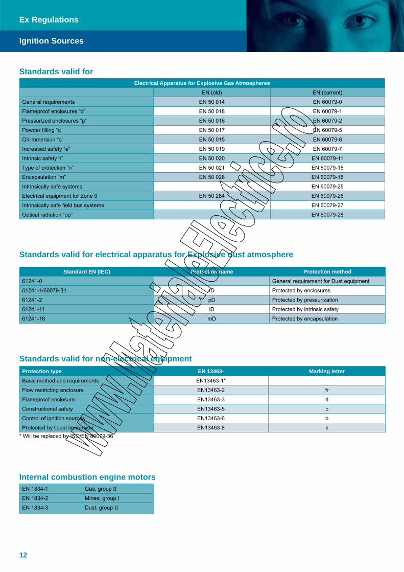
Standards valid forElectrical Apparatus for Explosive Gas Atmospheres
EN (old) EN (current)
General requirements EN 50 014 EN 60079-0
Flameproof enclosures “d” EN 50 018 EN 60079-1
Pressurized enclosures “p“ EN 50 016 EN 60079-2
Powder filling “q“ EN 50 017 EN 60079-5
Oil immersion “o” EN 50 015 EN 60079-6
Increased safety “e” EN 50 019 EN 60079-7
Intrinsic safety “i” EN 50 020 EN 60079-11
Type of protection “n” EN 50 021 EN 60079-15
Encapsulation “m” EN 50 028 EN 60079-18
Intrinsically safe systems EN 60079-25
Electrical equipment for Zone 0 EN 50 284 EN 60079-26
Intrinsically safe field bus systems EN 60079-27
Optical radiation “op” EN 60079-28
Standards valid for electrical apparatus for Explosive dust atmosphere
Standard EN (IEC) Protection name Protection method61241-0 General requirement for Dust equipment
61241-1/60079-31 tD Protected by enclosures
61241-2 pD Protected by pressurization
61241-11 iD Protected by intrinsic safety
61241-18 mD Protected by encapsulation
Standards valid for non-electrical equipmentProtection type EN 13463- Marking letterBasic method and requirements EN13463-1*
Flow restricting enclosure EN13463-2 fr
Flameproof enclosure EN13463-3 d
Constructional safety EN13463-5 c
Control of ignition sources EN13463-6 b
Protected by liquid immersion EN13463-8 k* Will be replaced by ISO/EN 80079-36
Internal combustion engine motorsEN 1834-1 Gas, group II
EN 1834-2 Mines, group I
EN 1834-3 Dust, group II
Ex Regulations
Ignition Sources

13
Ex Regulations
Marking
Flameproof enclosures (IEC/EN 60079-1) Ex dThe enclosures are constructed so that internal explosions can not be transmitted to the external atmosphere
Increased safety (IEC/EN 60079-7) Ex ePrevention of ignition sources by fail safe design (only simple electric components)
Intrinsic safety (IEC/EN 60079-11) Ex ia/ib/icLimitation of the energy stored in the electrical circuits category “ia”and “ib”, “simple” apparatus, “associated” apparatus, safety barriersInstallation: Safety values (Uo, Io, Po, Lo, Co) and clearances
Type n (IEC/EN 60079-15 : Zone 2) Ex nA, Non-sparkingNo ignition source in normal operation (no sparks, no hot surfaces) Ex nC, Protected sparking Ex nR, Restricted breathing Ex nL, Energy limited
Oil immersion (IEC/EN 60079-6) Ex oElectrical parts are submerged in oil
Pressurized apparatus (IEC/EN 60079-2) Ex px, Gb (to safe area)Electrical parts are purged and pressurized with a protective gas Ex py, Gb (to Gc)(air or inert gas) Ex pz, Gc (to safe area)Installation: Purge and pressure control/shut down device
Powder filling (IEC/EN 60079-5) Ex qElectrical parts are submerged in a quartz powder
Encapsulation (IEC/EN 60079-18) Ex ma/mbElectrical parts are encapsulated in a specific resin.
Protection Methods

14
EPL (Equipment Protection Level) according to IEC/EN 60079-0 standard
Definition:The level of protection assigned to equipment based on its likelihood of becoming a source of ignition and distinguishing the differences between explosive gas atmospheres, explosive dust atmospheres, and the explosive atmosphere in mines susceptible to firedamp.
Link between Zones, Atex categories and EPL:
Area towards Equipment
EN 60079-0 Directive 94-9-ECProduct directive (Atex 100)
EN60079-10X Directive 99/92/EC User directive (Atex 137)
EPL GroupLevel of
protectionEquipment
groupEquipment category
Zones Hazardous quantitiesExtent of protective
measure (Risk)
MaI
Very highI
M1N/A
Without specific methane concentration
Safe with 2 faults, rare and foreseen
Mb High M2With specific methane
concentrationSafe with 1 fault,
foreseen
Ga
II
Very high
II
1G 0 Often/longer periodsSafe with 2 faults, rare
and foreseen
Gb High 2G 1 OccasionallySafe with 1 fault,
foreseen
Gc Enhanced 3G 2 Rear/most likely never Normal
Da
III
Very high 1D 20 Often/longer periodsSafe with 2 faults, rare
and foreseen
Db High 2D 21 OccasionallySafe with 1 fault,
foreseen
Dc Enhanced 3D 22 Rear/most likely never Normal
Why EPL (Atex categories);Historically it has been acceptable to install equipment into specific zones based on the type of protection.
In some cases it has been shown that the type of protection may been divided into different levels of protection that can be correlated against each Zone. A better risk assessment would consider all factors. When using a risk assessment ap-proach instead of the inflexible approach of the past linking equipment to Zones the inherent ignition risk of the equipment is clearly indicated, no matter what type of protection is used.
An example using a risk assessment approach:Plant operators often make intuitive decisions on extending (or restricting) their Zones in order to compensate for this inflexibility. A typical example is the installation of “Zone 1 Type” navigation equipment in Zone 2 areas of offshore oil production platforms, so that the navigation equipment can remain functional even in the presence of a totally unexpected and prolonged gas release. On the other hand, it is reasonable for the owner of a remote, well secured, small pumping station to drive the pump with a “Zone 2 Type” motor, even in Zone 1, if the total amount of gas available to explode is small and the risk to life and property from such as explosion can be discounted.
The situation became more complex with the publication of the first edition of IEC 60079-26 which introduced additional requirements to be applied for equipment intended to be used in Zone 0. Prior to this, Ex ia was considered to be the only technique acceptable in Zone 0.
It has been recognized that it is beneficial to identify and mark all products according to their inherent ignition risk. This makes equipment selection easier and a risk assessment approach, more appropriate.
Ex Regulations
Equipment Protection Level
15
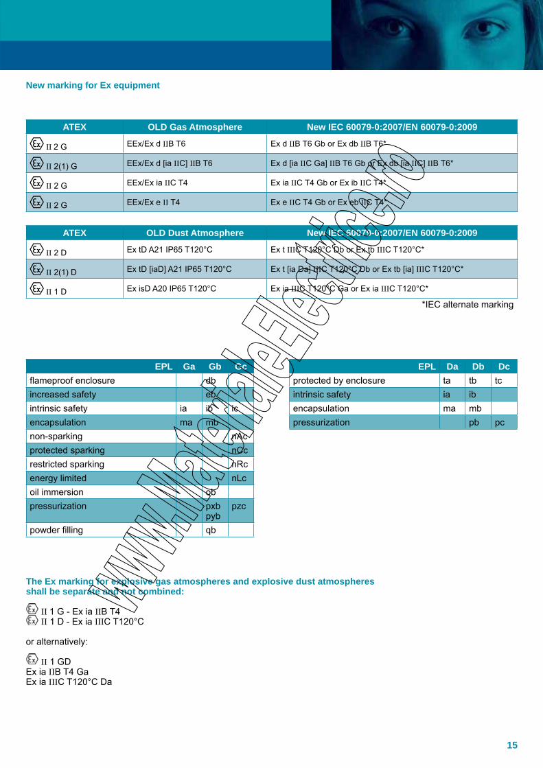
ATEX OLD Gas Atmosphere New IEC 60079-0:2007/EN 60079-0:2009
II 2 G EEx/Ex d IIB T6 Ex d IIB T6 Gb or Ex db IIB T6*
II 2(1) G EEx/Ex d [ia IIC] IIB T6 Ex d [ia IIC Ga] IIB T6 Gb or Ex db [ia IIC] IIB T6*
II 2 G EEx/Ex ia IIC T4 Ex ia IIC T4 Gb or Ex ib IIC T4*
II 2 G EEx/Ex e II T4 Ex e IIC T4 Gb or Ex eb IIC T4*
ATEX OLD Dust Atmosphere New IEC 60079-0:2007/EN 60079-0:2009
II 2 D Ex tD A21 IP65 T120°C Ex t IIIC T120°C Db or Ex tb IIIC T120°C*
II 2(1) D Ex tD [iaD] A21 IP65 T120°C Ex t [ia Da] IIIC T120°C Db or Ex tb [ia] IIIC T120°C*
II 1 D Ex isD A20 IP65 T120°C Ex ia IIIC T120°C Ga or Ex ia IIIC T120°C*
*IEC alternate marking
EPL Ga Gb Gc EPL Da Db Dcflameproof enclosure db protected by enclosure ta tb tcincreased safety eb intrinsic safety ia ibintrinsic safety ia ib ic encapsulation ma mbencapsulation ma mb pressurization pb pcnon-sparking nAcprotected sparking nCcrestricted sparking nRcenergy limited nLcoil immersion obpressurization pxb
pybpzc
powder filling qb
The Ex marking for explosive gas atmospheres and explosive dust atmospheres shall be separate and not combined:
II 1 G - Ex ia IIB T4 II 1 D - Ex ia IIIC T120°C
or alternatively:
II 1 GDEx ia IIB T4 GaEx ia IIIC T120°C Da
New marking for Ex equipment
161616616161161666666
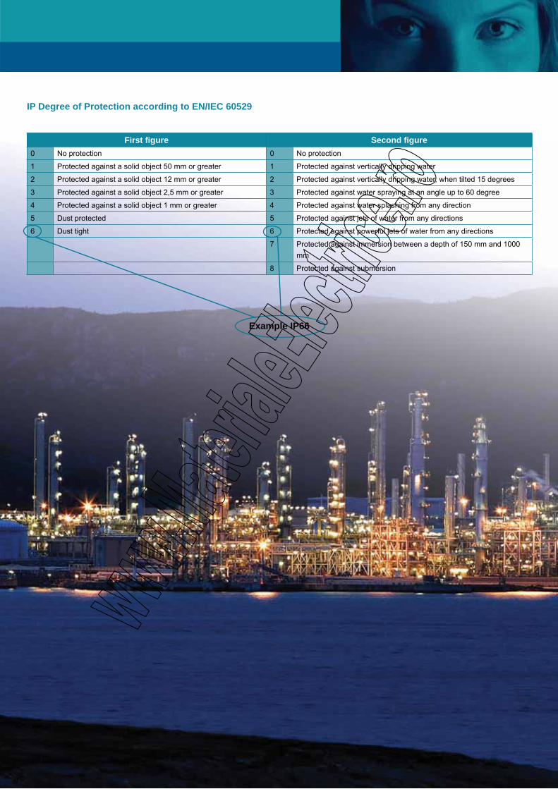
IP Degree of Protection according to EN/IEC 60529
First figure Second figure0 No protection 0 No protection
1 Protected against a solid object 50 mm or greater 1 Protected against vertically dripping water
2 Protected against a solid object 12 mm or greater 2 Protected against vertically dripping water, when tilted 15 degrees
3 Protected against a solid object 2,5 mm or greater 3 Protected against water spraying at an angle up to 60 degree
4 Protected against a solid object 1 mm or greater 4 Protected against water splashing from any direction
5 Dust protected 5 Protected against jets of water from any directions
6 Dust tight 6 Protected against powerful jets of water from any directions
7 Protected against immersion between a depth of 150 mm and 1000 mm
8 Protected against submersion
Example IP66
171171717171717
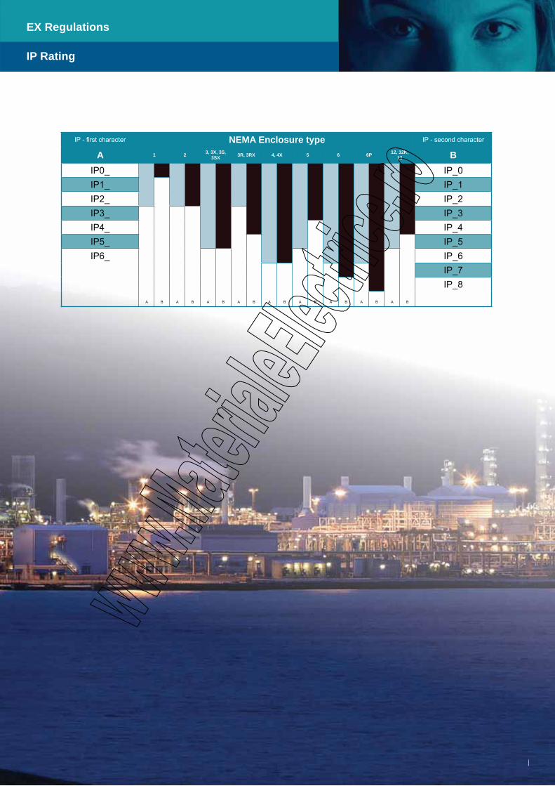
EX Regulations
IP Rating
IP - first character NEMA Enclosure type IP - second character
A 1 2 3, 3X, 3S, 3SX 3R, 3RX 4, 4X 5 6 6P 12, 12K,
13 BIP0_ IP_0IP1_
B
IP_1IP2_ IP_2IP3_
A A B A
IP_3IP4_
B
IP_4IP5_
B B
IP_5IP6_
A B A A
IP_6
A B A A
IP_7
B
IP_8
B
18
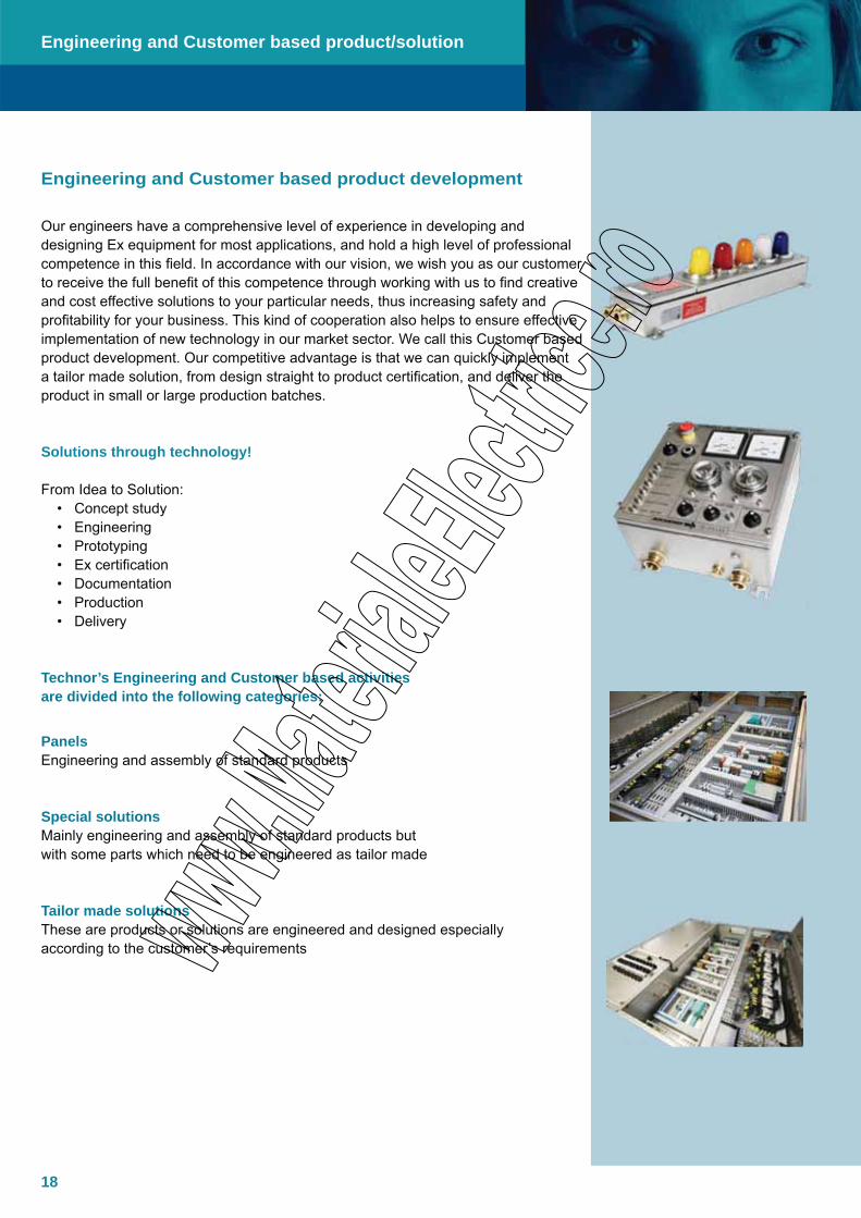
Our engineers have a comprehensive level of experience in developing and designing Ex equipment for most applications, and hold a high level of professional competence in this field. In accordance with our vision, we wish you as our customer to receive the full benefit of this competence through working with us to find creative and cost effective solutions to your particular needs, thus increasing safety and profitability for your business. This kind of cooperation also helps to ensure effective implementation of new technology in our market sector. We call this Customer based product development. Our competitive advantage is that we can quickly implement a tailor made solution, from design straight to product certification, and deliver the product in small or large production batches.
Solutions through technology!
From Idea to Solution: • Concept study • Engineering • Prototyping • Ex certification • Documentation • Production • Delivery
Technor’s Engineering and Customer based activities are divided into the following categories:
PanelsEngineering and assembly of standard products
Special solutionsMainly engineering and assembly of standard products but with some parts which need to be engineered as tailor made
Tailor made solutionsThese are products or solutions are engineered and designed especially according to the customer’s requirements
Engineering and Customer based product development
Engineering and Customer based product/solution

19
PanelsEngineering and building of a solution based on standard Ex components (with or without incorporation of standard industrial components), such as control panels, switch gears, motor starters etc.Typical examples are:
Ex d panels • Ex e/ed panels • Ex p• Ex n (Zone 2 only)•
Special solutionModifying existing Ex components to be adapted to certain tailor requirements,such as: CCTV applications, Remote I/O panels, HMI applications (LCD display and PC solutions), pressurized systems, wireless measuring systems, light equipment etc. Typical examples can include:
Ex d solutions • Ex e/ed solutions• Ex p• Ex n (for Zone 2)•
Tailor made solutions (are mainly OEM products/solutions)Creating and engineering of solution totally from the very beginning. Typical applications are communication systems including wire, fibre optical, wireless transfer, CCTV solutions, measuring systems, different types of switch/control gear, light equipment etc.
The range of OEM products are designed to meet the clients demands, and are usually used within an industry where an explosive atmosphere may be present.
If you come up with a unique product idea which is going to be used in hazardous area, we can use our long-standing competence and experience within the Ex field to ensure that you achieve your vision.
We can tailor make products using all Ex protection methods in close relation-ship with our clients and have them verified/certified for II 3 G/D (Zone 2/ 22), II 2 G/D (Zone 1/ 21) , II 1 G/D (Zone 0/ 20) or a combination of these. For certification we are using partners such as INERIS, DNV, Nemko, IMQ etc.
Technor can offer you more than 20 years of experience with tailor made Ex products.
Engineering and Customer based product/solution

20
This is how we can carry out a project:
Analyse the needs and valid directives/regulations•
Develop initial ideas for the project covering the following:• - Mechanical (including IP NEMA rating, extreme temperature range, involved materials etc) - Electrical - Method of Ex protection - Budget price
Create a model of the solution - 2D or 3D format•
Generation of prototypes for validation, if necessary•
Ex certification (certificate to be issued by Notified Bodies/Certification Bodies)• - Atex - IECEx - Gost - Others (North America, South America etc.)
Creating product documentation including:• - Production documentation - Production procedures - CE verification - Declaration of Conformity - User manual - Other relevant demands for equipment to be used in hazardous area
Our client can receive the product from our production facilities as a part •
product or a fully functional product. These can be delivered as follows: - The product labelled with Technor - The product labelled under the name of the client (this solution requires a production license in the name of the product owner)
The client will receive a product that meets the requirements for use in • hazardous area without requiring his own competence regarding Ex or production setup for such products.
Engineering and Customer based product/solution

21
Pressurized cabinets and systems (Ex p)
A typical project schedule for a pressurized system can be as follows:
Analysing the specific requirements from the client and clarifying these with the client. This includes details such as environment conditions, material strength, physical dimensions, electrical requirements, etc. An important task at this stage is also to verify that all client’s requirements can be solved within the actual Ex standards and directives.
Construction of the actual panel/cabinet according to the demands and specifications from the client.
Selecting the correct control systems according to the demands and specifications given by the client, such as required cooling, limitation in purge time, how much air/ inert gas is available etc.
At this point, any shut-down requirements need to be addressed and taken into consideration before the actual control system is selected.
When the client has approved the construction-plans, the actual panel/ cabinet can be manufactured.
Then the physical assembly of the system can start in our specialised manufacturing facility with skilled personnel, including the internal components (including possible free issue items) which are to be protected by pressurisation and the purge/ Ex p control system.
Adjusting of control system parameters so that the pressurised control system functions correctly regarding all requirements.
Fulfilling all purge and temperature tests according to the mandatory standards (EN/IEC 60079-0 and 60079-2).
Final functional test.
Creating the required documentation package, including all client requirements.
Write the user manual, as a minimum to meet the requirements in EN/IEC 60079-0 and 60079-2 and the Directive 94/9/EC.
Applying for the Certificate of Conformity.
Issuing the EC Declaration of Conformity (EC D.O.C.).
Handover (eventual FAT: Final Acceptance test) and delivery of the complete system.
Project Shedule
Pressurized Cabinets and Systems
22

23
Terminal Boxes
AQ/AL and AR/AL SeriesJunction Boxes, Ex e / Ex ia, Copper free Aluminium
TNCN Junction Boxes, Ex e/i, Stainless steel AISI 316L
TNUPJunction Boxes, Ex e / Ex ia, GRP
24
27
29
24
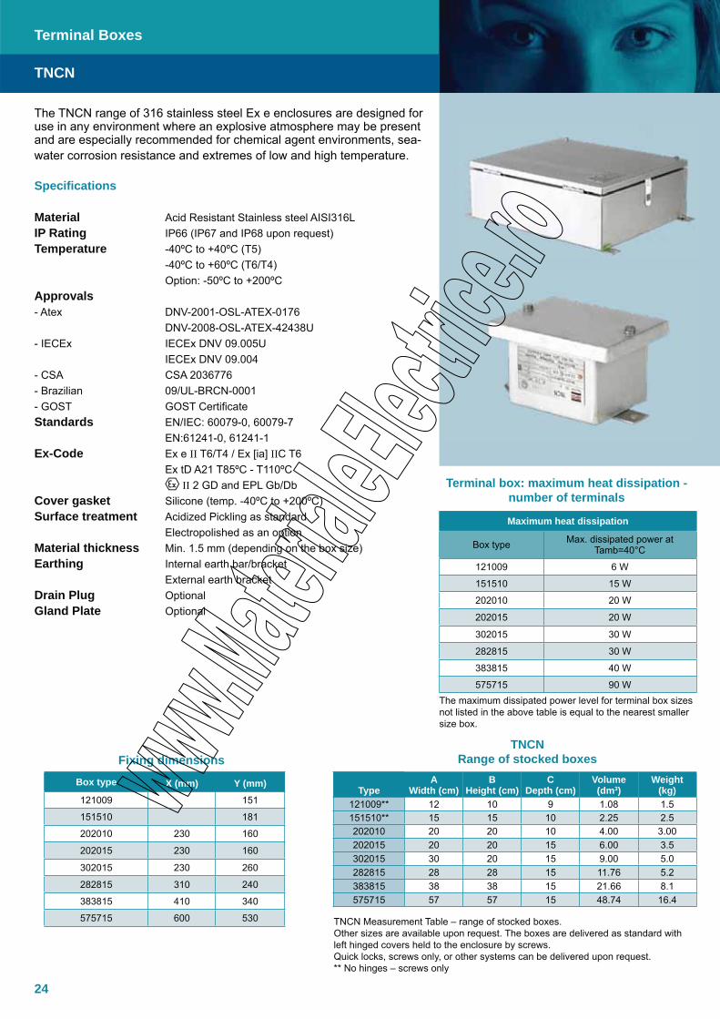
The TNCN range of 316 stainless steel Ex e enclosures are designed for use in any environment where an explosive atmosphere may be present and are especially recommended for chemical agent environments, sea-water corrosion resistance and extremes of low and high temperature.
Specifications
Material Acid Resistant Stainless steel AISI316LIP Rating IP66 (IP67 and IP68 upon request)Temperature -40ºC to +40ºC (T5) -40ºC to +60ºC (T6/T4) Option: -50ºC to +200ºCApprovals- Atex DNV-2001-OSL-ATEX-0176 DNV-2008-OSL-ATEX-42438U- IECEx IECEx DNV 09.005U IECEx DNV 09.004- CSA CSA 2036776- Brazilian 09/UL-BRCN-0001- GOST GOST CertificateStandards EN/IEC: 60079-0, 60079-7 EN:61241-0, 61241-1Ex-Code Ex e II T6/T4 / Ex [ia] IIC T6 Ex tD A21 T85ºC - T110ºC II 2 GD and EPL Gb/Db Cover gasket Silicone (temp. -40ºC to +200ºC)Surface treatment Acidized Pickling as standard Electropolished as an optionMaterial thickness Min. 1.5 mm (depending on the box size)Earthing Internal earth bar/bracket External earth bracketDrain Plug OptionalGland Plate Optional
TNCN
Terminal Boxes
Maximum heat dissipation
Box type Max. dissipated power at Tamb=40°C
121009 6 W
151510 15 W
202010 20 W
202015 20 W
302015 30 W
282815 30 W
383815 40 W
575715 90 W
TypeA
Width (cm)B
Height (cm)C
Depth (cm)Volume (dm3)
Weight (kg)
121009** 12 10 9 1.08 1.5151510** 15 15 10 2.25 2.5202010 20 20 10 4.00 3.00202015 20 20 15 6.00 3.5302015 30 20 15 9.00 5.0282815 28 28 15 11.76 5.2383815 38 38 15 21.66 8.1575715 57 57 15 48.74 16.4
Terminal box: maximum heat dissipation - number of terminals
TNCN Range of stocked boxes
The maximum dissipated power level for terminal box sizes not listed in the above table is equal to the nearest smaller size box.
TNCN Measurement Table – range of stocked boxes.Other sizes are available upon request. The boxes are delivered as standard with left hinged covers held to the enclosure by screws. Quick locks, screws only, or other systems can be delivered upon request.** No hinges – screws only
Box type X (mm) Y (mm)121009 151
151510 181
202010 230 160
202015 230 160
302015 230 260
282815 310 240
383815 410 340
575715 600 530
Fixing dimensions

25
A or B Width/ Height(cm)
CDepth(cm) M20 M25
15
10 8 6
15 12 9
20 16 12
27 24 15
20
10 10 10
15 15 15
20 25 20
27 35 30
30
10 15 14
15 24 21
20 40 28
27 56 42
38
10 20 18
15 30 27
20 50 36
27 70 54
40
10 22 18
15 3 27
20 55 36
27 77 54
45
10 24 20
15 36 30
20 60 40
27 84 60
57
10 32 26
15 48 39
20 80 52
30 128 78
76
10 42 36
15 63 54
20 105 72
27 147 108
TNCN
Terminal Boxes
Entry MatrixThis table lists our recommendations for the maximum quantity of glands for installation in 1 face (the width column in the table) on TNCN Junction Boxes.
Note: Recommended quantity. MCT-frames can be fitted in boxes with a minimum depth of 20 cm.
Dimensions
Top/Bottom Side (L+R)Box A B C D
202010 148 36 148 81202015 148 81 148 81302015 248 81 148 81282815 228 81 228 81383815 328 81 328 81575715 518 81 518 81
TNCN 121009/151509
TNCN 202010-575715

26
27
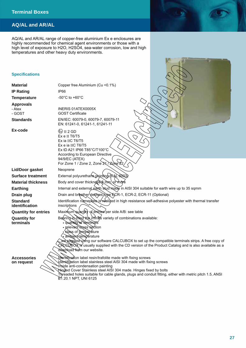
AQ/AL and AR/AL range of copper-free aluminium Ex e enclosures are highly recommended for chemical agent environments or those with a high level of exposure to H2O, H2SO4, sea-water corrosion, low and high temperatures and other heavy duty environments.
Specifications
Material Copper free Aluminium (Cu <0.1%)
IP Rating IP66
Temperature -50°C to +60°C
Approvals- Atex- GOST
INERIS 01ATEX0005X GOST Certificate
Standards EN/IEC: 60079-0, 60079-7, 60079-11EN: 61241-0, 61241-1, 61241-11
Ex-code II 2 GDEx e II T6/T5Ex ia IIC T6/T5Ex e ia IIC T6/T5Ex tD A21 IP66 T85°C/T100°CAccording to European Directive 94/9/EC (ATEX)For Zone 1 / Zone 2, Zone 21 / Zone 22
Lid/Door gasket Neoprene
Surface treatment External polyurethane painting (RAL 6003)
Material thickness Body and cover thickness 8 mm, or more
Earthing Internal and external earth stud made in AISI 304 suitable for earth wire up to 35 sqmm
Drain plug Drain and breather devices type ECR-1, ECR-2, ECR-11 (Optional)
Standard identification
Identification nameplate is realized in high resistance self-adhesive polyester with thermal transfer inscriptions
Quantity for entries Maximum quantity of entries per side A/B: see table
Quantity for terminals
Bearing in mind the infinite variety of combinations available: • quantity of terminals• relevant cross section• class of temperature• ambient temperature
...we suggest using our software CALCUBOX to set up the compatible terminals strips. A free copy of CALCUBOX is usually supplied with the CD version of the Product Catalog and is also available as a download from our website.
Accessories on request
Identification label resin/trafolite made with fixing screwsIdentification label stainless steel AISI 304 made with fixing screwsInside anti-condensation paintingHinged Cover Stainless steel AISI 304 made. Hinges fixed by boltsThreaded holes suitable for cable glands, plugs and conduit fitting, either with metric pitch 1.5, ANSI B1.20.1 NPT, UNI 6125
Terminal Boxes
AQ/AL and AR/AL

28
AQ/AL and AR/AL
Terminal Boxes
Entries surface available
Box Type CodeEntries surface available
Short side A Length side BAQ-8A HTH AL A.4200.04 138 x 270 138 x 270AR-8 HTH AL A.4200.05 90 x 260 90 x 417
AR-8A HTH AL A.4200.06 90 x 417 90 x 417AR-8A S AL A.4200.07 90 x 260 90 x 590AR-8A L AL A.4200.08 160 x 490 160 x 750
Maximum number of entries½” M20 ¾” M25 1” M32 1 ¼” M40 1 ½” M50 2” M63 2 ½” M75 3” M80
Box Type A B A B A B A B A B A B A B A BAQ-8A HTH AL 31** 31** 18* 18* 16* 16* 7 7 5 5 4 4 4 4 3 3AR-8 HTH AL 36** 24** 20* 14* 18* 12* 7 5 6 4 5 3 4 3 4 2AR-8A HTH AL 36** 36** 20* 20* 18* 18* 7 7 6 6 5 5 4 4 4 4AR-8A S AL 50** 34** 28* 20* 25* 17* 10 7 8 6 7 4 6 4 6 3AR-8A L AL 76*** 48*** 48*** 30*** 39*** 24*** 22* 14* 20* 12* 8 5 7 4 6 4
(*) Located on two rows(**) Located on three rows(***) Located on four rows
Range: Enclosures with High thickness wall (Hth)
Box Type Code
External Dimensions Internal DimensionsFixing
Dimensions Mounting Plate Wallthickness
(mm)Weight
KgA
(mm)B
(mm)C
(mm)D
(mm)E
(mm)F
(mm)G
(mm)H
(mm)Dimension
(mm)Weight
KgAQ-8A HTH AL A.4200.04 332 332 178 302 302 155 315 310 294x294 1.25 12 8.00AR-8 HTH AL A.4200.05 330 495 171 304 455 151 470 320 270x455 1.80 12 12.40AR-8A HTH AL A.4200.06 495 495 171 461 461 151 470 470 432x432 3.00 12 17.30AR-8A S AL A.4200.07 330 660 177 302 622 150 635 305 270x622 2.70 12 16.70AR-8A L AL A.4200.08 580 840 205 540 800 178 810 560 500x760 10 12 36.00
Dimensions
29
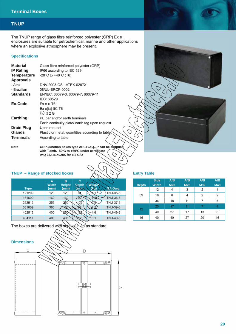
The TNUP range of glass fibre reinforced polyester (GRP) Ex e enclosures are suitable for petrochemical, marine and other applications where an explosive atmosphere may be present.
Specifications
Material Glass fibre reinforced polyester (GRP)IP Rating IP66 according to IEC 529Temperature -20ºC to +40ºC (T6)Approvals- Atex DNV-2003-OSL-ATEX-0207X- Brazilian 08/UL-BRCP-0002Standards EN/IEC: 60079-0, 60079-7, 60079-11 IEC: 60529Ex-Code Ex e II T6 Ex e[ia] IIC T6 II 2 GEarthing PE bar and/or earth terminals Earth continuity plate/ earth tag upon requestDrain Plug Upon requestGlands Plastic or metal, quantities according to tableTerminals According to table
Note GRP Junction boxes type AR...P/AQ...P can be supplied with T.amb. -50ºC to +60ºC under certificate IMQ 08ATEX028X for II 2 G/D
TNUP
Terminal Boxes
Type
A Width(mm)
B Height(mm)
C Depth(mm)
Weight(kg) GA-Dwg.
121209 123 120 91 1.1 TNU-35-6161609 160 160 92 1.5 TNU-36-6252512 255 250 120 2.9 TNU-37-6361609 360 160 92 2.5 TNU-39-6402512 400 250 120 4.3 TNU-49-6
404117 400 405 165 6.1 TNU-40-6
The boxes are delivered with screws in lid as standard
DepthSide
WidthA/BM20
A/B M25
A/B M32
A/B M40
09
12 4 3 2 1
16 6 4 2 2
36 18 11 7 5
1225 17 11 7 4
40 27 17 13 6
16 40 40 27 20 16
Entry TableTNUP – Range of stocked boxes
Dimensions
30
31
Control Equipment - Components
PushbuttonHarmAtex pushbutton, Ex ed, Metal and Platstic
Emergency MushroomHarmAtex Emergency Mushroom, Ex ed, Metal and Plastic
Selector SwitchHarmAtex Selector Switch, Ex ed, Metal and Plastic
Illuminated SwitchHarmAtex Illuminated Switch, Ex ed, Metal and Plastic
Pilot LightHarmAtex Pilot Light, Ex ed, Metal and Plastic
ContactblockHarmAtex Contactblock, Ex ed, Metal and Plastic
PushbuttonsEx d Components
Pilot LampsEx d Components
Rotary Selector SwitchesEx d Components
ContactsEx d Components
32
34
35
37
39
40
41
42
43
43
32
Control Equipment - Components
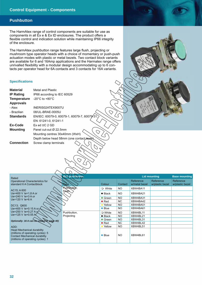
The HarmAtex range of control components are suitable for use as components in all Ex e & Ex tD enclosures. The product offers a flexible control and indication solution while maintaining IP66 integrity of the enclosure.
The HarmAtex pushbutton range features large flush, projecting or mushroom type operator heads with a choice of momentary or push-push actuation modes with plastic or metal bezels. Two contact block variants are available for 6 and 16Amp applications and the Harmatex range offers unrivalled flexibility with a modular design accommodating up to 6 con-tacts per operator head for 6A contacts and 3 contacts for 16A variants.
Specifications
Material Metal and PlasticIP Rating IP66 according to IEC 60529Temperature -20°C to +80°CApprovals - Atex INERIS02ATEX9007U- Brazilian 08/UL-BRAE-0005UStandards EN/IEC: 60079-0, 60079-1, 60079-7, 60079-31, EN: 61241-0, 61241-1Ex-Code Ex ed IIC 2 GDMounting Panel cut-out Ø 22.5mm Mounting centres 30x40mm (WxH) Depth below head 58mm (one contact layer)Connection Screw clamp terminals
Pushbutton
Rated Operational Characteristics for standard 6 A Contactblock
AC15; A 600 Ue=400 V Ie=1,8 A or Ue=240 V Ie=3 A or Ue=120 V Ie=6 A
DC13; Q600 Ue=400 V Ie=0.15 A or Ue=250 V Ie=0.27 A or Ue=125 V Ie=0.55 A
Optionally: 16 A can be used (ref. page 40)
ADD:Head Mechanical durability(millions of operating cycles): 5Contact Mechanical durability(millions of operating cycles): 1
Ø22 pushbutton Lid mounting Base mounting
Type Colour ContactReference w/metal bezel
Reference w/plastic bezel
Reference w/plastic bezel
Pushbutton, Flush
White NO XBW4BA11
Black NO XBW4BA21 Green NO XBW4BA31 Red NC XBW4BA42 Yellow NO XBW4BA51 Blue NO XBW4BA61
Pushbutton, Projecting
White NO XBW4BL11 Black NO XBW4BL21 Green NO XBW4BL31 Red NC XBW4BL42 Yellow NO XBW4BL51
Blue NO XBW4BL61
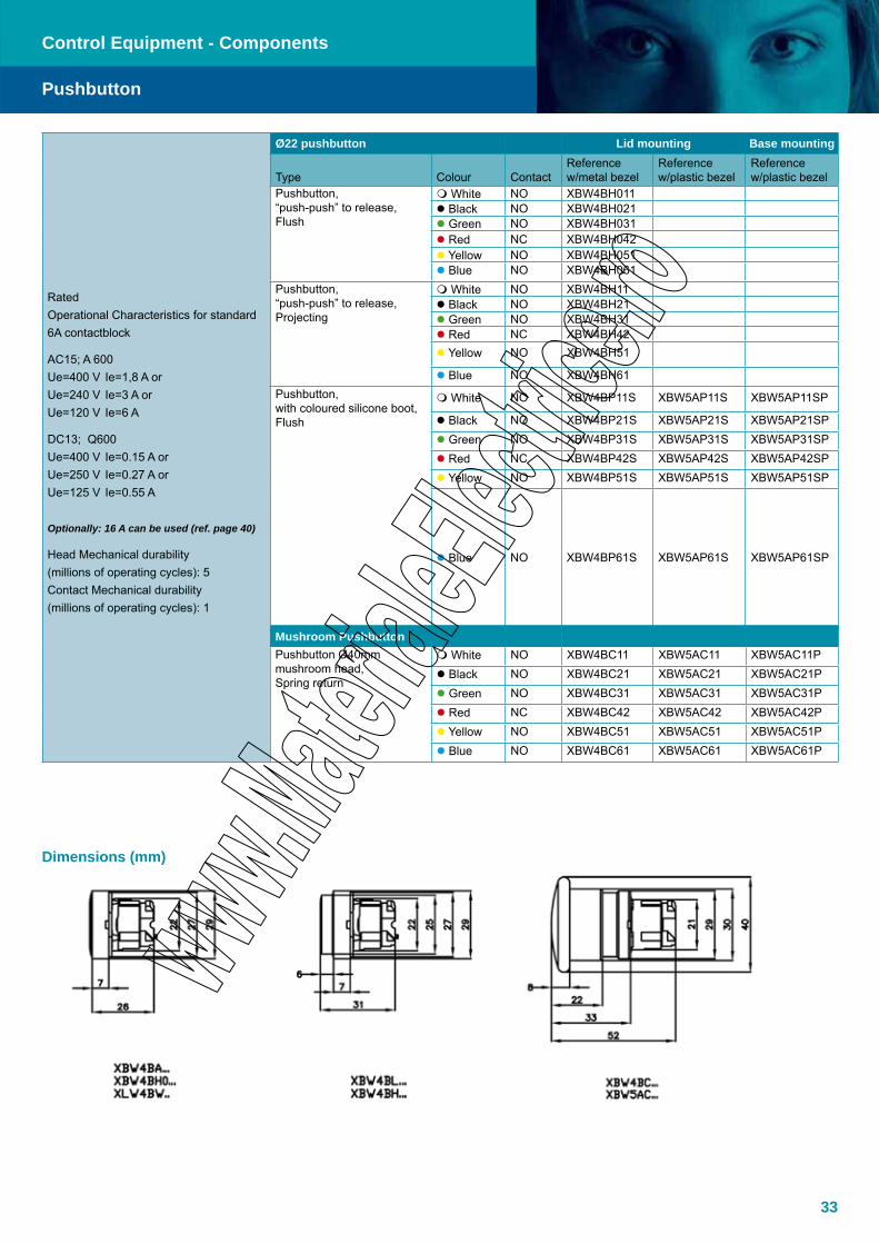
33
Mushroom PushbuttonPushbutton Ø40mm mushroom head, Spring return
White NO XBW4BC11 XBW5AC11 XBW5AC11P Black NO XBW4BC21 XBW5AC21 XBW5AC21P Green NO XBW4BC31 XBW5AC31 XBW5AC31P Red NC XBW4BC42 XBW5AC42 XBW5AC42P Yellow NO XBW4BC51 XBW5AC51 XBW5AC51P Blue NO XBW4BC61 XBW5AC61 XBW5AC61P
Rated Operational Characteristics for standard 6A contactblock
AC15; A 600 Ue=400 V Ie=1,8 A or Ue=240 V Ie=3 A or Ue=120 V Ie=6 A
DC13; Q600 Ue=400 V Ie=0.15 A or Ue=250 V Ie=0.27 A or Ue=125 V Ie=0.55 A
Optionally: 16 A can be used (ref. page 40)
Head Mechanical durability(millions of operating cycles): 5Contact Mechanical durability(millions of operating cycles): 1
Ø22 pushbutton Lid mounting Base mounting
Type Colour ContactReference w/metal bezel
Reference w/plastic bezel
Reference w/plastic bezel
Pushbutton, “push-push” to release, Flush
White NO XBW4BH011 Black NO XBW4BH021 Green NO XBW4BH031 Red NC XBW4BH042 Yellow NO XBW4BH051 Blue NO XBW4BH061
Pushbutton, “push-push” to release, Projecting
White NO XBW4BH11 Black NO XBW4BH21 Green NO XBW4BH31 Red NC XBW4BH42 Yellow NO XBW4BH51
Blue NO XBW4BH61Pushbutton, with coloured silicone boot, Flush
White NO XBW4BP11S XBW5AP11S XBW5AP11SP
Black NO XBW4BP21S XBW5AP21S XBW5AP21SP Green NO XBW4BP31S XBW5AP31S XBW5AP31SP Red NC XBW4BP42S XBW5AP42S XBW5AP42SP Yellow NO XBW4BP51S XBW5AP51S XBW5AP51SP
Blue NO XBW4BP61S XBW5AP61S XBW5AP61SP
Control Equipment - Components
Pushbutton
Dimensions (mm)
34
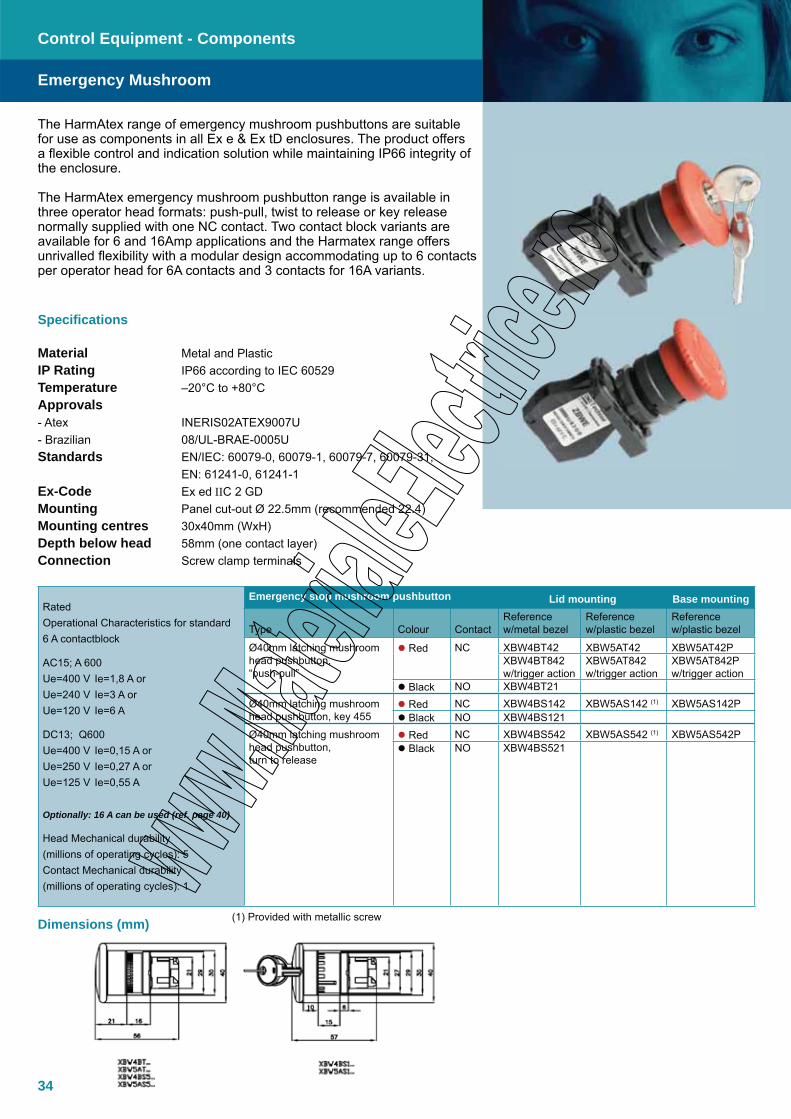
The HarmAtex range of emergency mushroom pushbuttons are suitable for use as components in all Ex e & Ex tD enclosures. The product offers a flexible control and indication solution while maintaining IP66 integrity of the enclosure.
The HarmAtex emergency mushroom pushbutton range is available in three operator head formats: push-pull, twist to release or key release normally supplied with one NC contact. Two contact block variants are available for 6 and 16Amp applications and the Harmatex range offers unrivalled flexibility with a modular design accommodating up to 6 contacts per operator head for 6A contacts and 3 contacts for 16A variants.
Specifications
Material Metal and PlasticIP Rating IP66 according to IEC 60529Temperature –20°C to +80°CApprovals - Atex INERIS02ATEX9007U- Brazilian 08/UL-BRAE-0005UStandards EN/IEC: 60079-0, 60079-1, 60079-7, 60079-31, EN: 61241-0, 61241-1Ex-Code Ex ed IIC 2 GDMounting Panel cut-out Ø 22.5mm (recommended 22.4)Mounting centres 30x40mm (WxH)Depth below head 58mm (one contact layer)Connection Screw clamp terminals
Control Equipment - Components
Rated Operational Characteristics for standard 6 A contactblock
AC15; A 600 Ue=400 V Ie=1,8 A or Ue=240 V Ie=3 A or Ue=120 V Ie=6 A
DC13; Q600 Ue=400 V Ie=0,15 A or Ue=250 V Ie=0,27 A or Ue=125 V Ie=0,55 A
Optionally: 16 A can be used (ref. page 40)
Head Mechanical durability(millions of operating cycles): 5Contact Mechanical durability(millions of operating cycles): 1
Emergency stop mushroom pushbutton Lid mounting Base mounting
Type Colour ContactReference w/metal bezel
Reference w/plastic bezel
Reference w/plastic bezel
Ø40mm latching mushroom head pushbutton, “push-pull”
Red NC XBW4BT42 XBW5AT42 XBW5AT42PXBW4BT842w/trigger action
XBW5AT842w/trigger action
XBW5AT842Pw/trigger action
Black NO XBW4BT21Ø40mm latching mushroom head pushbutton, key 455
Red NC XBW4BS142 XBW5AS142 (1) XBW5AS142P Black NO XBW4BS121
Ø40mm latching mushroom head pushbutton, turn to release
Red NC XBW4BS542 XBW5AS542 (1) XBW5AS542P Black NO XBW4BS521
(1) Provided with metallic screw
Emergency Mushroom
Dimensions (mm)
35
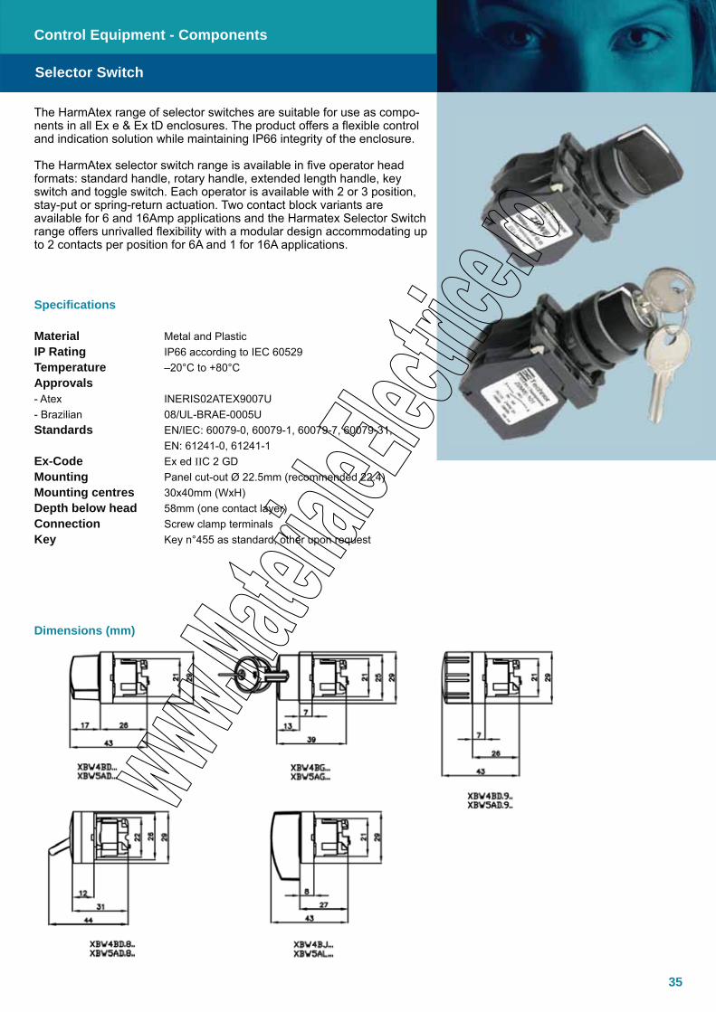
The HarmAtex range of selector switches are suitable for use as compo-nents in all Ex e & Ex tD enclosures. The product offers a flexible control and indication solution while maintaining IP66 integrity of the enclosure.
The HarmAtex selector switch range is available in five operator head formats: standard handle, rotary handle, extended length handle, key switch and toggle switch. Each operator is available with 2 or 3 position, stay-put or spring-return actuation. Two contact block variants are available for 6 and 16Amp applications and the Harmatex Selector Switch range offers unrivalled flexibility with a modular design accommodating up to 2 contacts per position for 6A and 1 for 16A applications.
Specifications
Material Metal and PlasticIP Rating IP66 according to IEC 60529Temperature –20°C to +80°CApprovals - Atex INERIS02ATEX9007U- Brazilian 08/UL-BRAE-0005UStandards EN/IEC: 60079-0, 60079-1, 60079-7, 60079-31, EN: 61241-0, 61241-1Ex-Code Ex ed IIC 2 GDMounting Panel cut-out Ø 22.5mm (recommended 22.4)Mounting centres 30x40mm (WxH)Depth below head 58mm (one contact layer)Connection Screw clamp terminalsKey Key n°455 as standard, other upon request
Control Equipment - Components
Selector Switch
Dimensions (mm)

36
Control Equipment - Components
Rated Operational Characteristics for standard 6 A contactblock
AC15; A 600
Ue=600 V Ie=1,8 A
Ue=240 V Ie=3 A
Ue=120 V Ie=6 A
DC13; Q600
Ue=400 V Ie=0.15 A
Ue=250 V Ie=0.27 A
Ue=125 V Ie= 0.55 A
Optionally: 16 A can be used (ref. page 40)
Selector switches and key switches Lid mounting Base mounting
Type Number and typeContact
Reference w/metal bezel
Reference w/plastic bezel
Reference w/plastic bezel
Selector switches with standard handle, black
2 stay put NO XBW4BD21 XBW5AD21 XBW5AD21P2 spring return NO XBW4BD41 XBW5AD41 XBW5AD41P3 stay put • NO + NO XBW4BD33 XBW5AD33 XBW5AD33P3 spring return to center • NO + NO XBW4BD53 XBW5AD53 XBW5AD53P
3 spring return from left to center • NO + NO XBW4BD73 XBW5AD73 XBW5AD73P3 spring return from right to center • NO + NO XBW4BD83 XBW5AD83 XBW5AD83P
Selector switches with wheel handle,black
2 stay put NO XBW4BD291 XBW5AD291 XBW5AD291P2 spring return NO XBW4BD491 XBW5AD491 XBW5AD491P3 stay put • NO + NO XBW4BD393 XBW5AD393 XBW5AD393P3 spring return to center • NO + NO XBW4BD593 XBW5AD593 XBW5AD593P3 spring return from left to center • NO + NO XBW4BD793 XBW5AD793 XBW5AD793P3 spring return from right to center • NO + NO XBW4BD893 XBW5AD893 XBW5AD893P
Selector switches with long handle,black
2 stay put NO XBW4BJ21 XBW5AJ21 XBW5AJ21P2 spring return NO XBW4BJ41 XBW5AJ41 XBW5AJ41P3 stay put • NO + NO XBW4BJ33 XBW5AJ33 XBW5AJ33P3 spring return to center • NO + NO XBW4BJ53 XBW5AJ53 XBW5AJ53P3 spring return from left to center • NO + NO XBW4BJ73 XBW5AJ73 XBW5AJ73P3 spring return from right to center • NO + NO XBW4BJ83 XBW5AJ83 XBW5AJ83P
Selector switches with key 455, black
2 stay put key withdrawal in left position NO XBW4BG21 XBW5AG21 XBW5AG21P2 stay put key withdrawal in both position NO XBW4BG41 XBW5AG41 XBW5AG41P2 spring return from right to left NO XBW4BG61 XBW5AG61 XBW5AG61P3 stay put, key withdrawal in 3 positions • NO + NO XBW4BG03 XBW5AG03 XBW5AG03P3 stay put, key withdrawal in center position • NO + NO XBW4BG33 XBW5AG33 XBW5AG33P3 stay put, key withdrawal in left or right position • NO + NO XBW4BG53 XBW5AG53 XBW5AG53P3 stay put, key withdrawal in left position • NO + NO XBW4BG93 XBW5AG93 XBW5AG93P3 stay put, key withdrawal in right position • NO + NO XBW4BG093 XBW5AG093 XBW5AG093P3 spring return from left to center • NO + NO XBW4BG13 XBW5AG13 XBW5AG13P3 spring return to center • NO + NO XBW4BG73 XBW5AG73 XBW5AG73P3 spring return from right to center, key withdrawal in center position
• NO + NO XBW4BG83 XBW5AG83 XBW5AG83P
3 spring return from right to center, key withdrawal in left position
• NO + NO XBW4BG083 XBW5AG083 XBW5AG083P
Toggle witches,black lever
2 stay put NO XBW4BD281 XBW5AD281 XBW5AD281P
2 spring return NO XBW4BD481 XBW5AD481 XBW5AD481P
• This selector switch can have an extra N/C contact block on the central position. The central N/C contact block is acting on left and right position. Contact us for further information.
Selector Switch
37
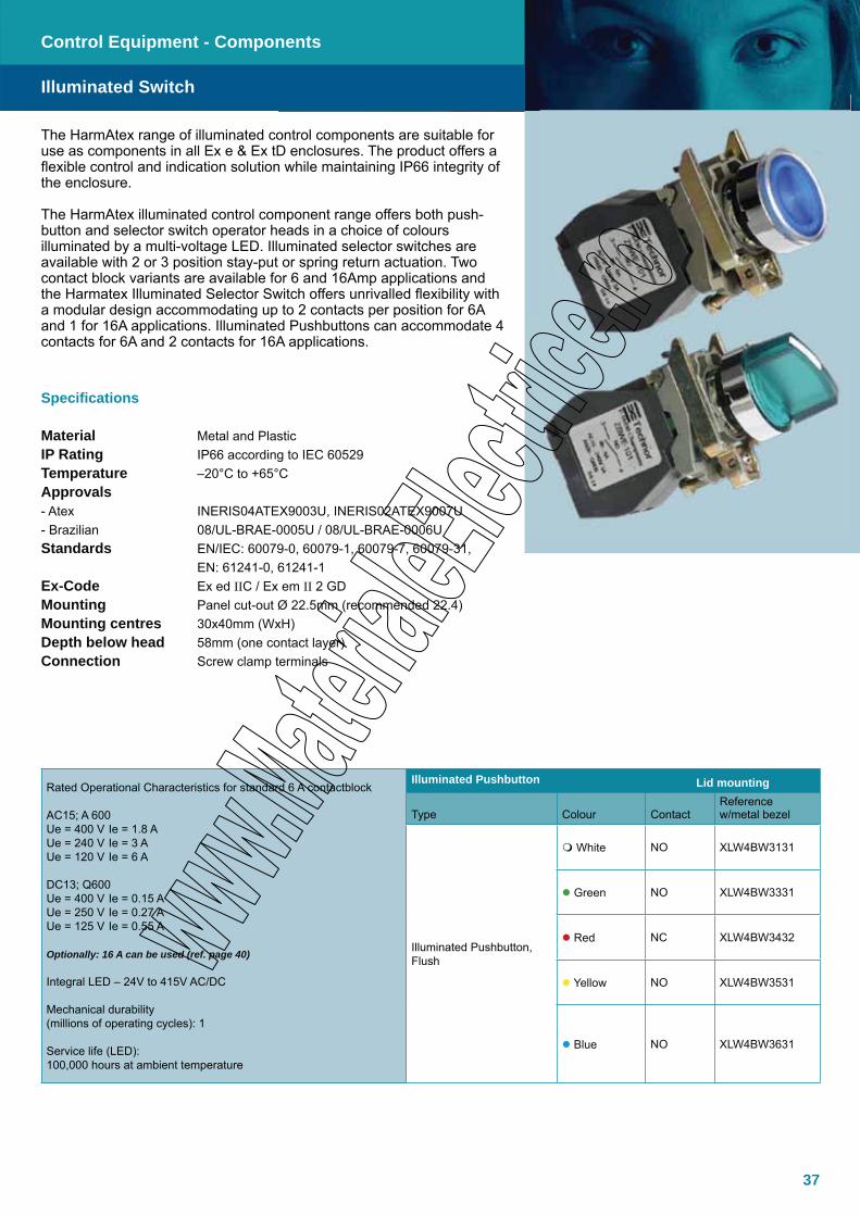
The HarmAtex range of illuminated control components are suitable for use as components in all Ex e & Ex tD enclosures. The product offers a flexible control and indication solution while maintaining IP66 integrity of the enclosure.
The HarmAtex illuminated control component range offers both push-button and selector switch operator heads in a choice of colours illuminated by a multi-voltage LED. Illuminated selector switches are available with 2 or 3 position stay-put or spring return actuation. Two contact block variants are available for 6 and 16Amp applications and the Harmatex Illuminated Selector Switch offers unrivalled flexibility with a modular design accommodating up to 2 contacts per position for 6A and 1 for 16A applications. Illuminated Pushbuttons can accommodate 4 contacts for 6A and 2 contacts for 16A applications.
Specifications
Material Metal and PlasticIP Rating IP66 according to IEC 60529Temperature –20°C to +65°CApprovals - Atex INERIS04ATEX9003U, INERIS02ATEX9007U- Brazilian 08/UL-BRAE-0005U / 08/UL-BRAE-0006UStandards EN/IEC: 60079-0, 60079-1, 60079-7, 60079-31, EN: 61241-0, 61241-1Ex-Code Ex ed IIC / Ex em II 2 GDMounting Panel cut-out Ø 22.5mm (recommended 22.4)Mounting centres 30x40mm (WxH)Depth below head 58mm (one contact layer)Connection Screw clamp terminals
Control Equipment - Components
Illuminated Switch
Rated Operational Characteristics for standard 6 A contactblock
AC15; A 600Ue = 400 V Ie = 1.8 A Ue = 240 V Ie = 3 A Ue = 120 V Ie = 6 A
DC13; Q600Ue = 400 V Ie = 0.15 AUe = 250 V Ie = 0.27 AUe = 125 V Ie = 0.55 A
Optionally: 16 A can be used (ref. page 40)
Integral LED – 24V to 415V AC/DC
Mechanical durability (millions of operating cycles): 1
Service life (LED): 100,000 hours at ambient temperature
Illuminated Pushbutton Lid mounting
Type Colour ContactReference w/metal bezel
Illuminated Pushbutton, Flush
White NO XLW4BW3131
Green NO XLW4BW3331
Red NC XLW4BW3432
Yellow NO XLW4BW3531
Blue NO XLW4BW3631

38
Control Equipment - Components
Illuminated selector switch Lead mounting
Type Colour ContactReference w/metal bezel
Illuminated Selector, 2 positions, stay put
White NO XLW4BK12131 Green NO XLW4BK12331 Red NC XLW4BK12432 Yellow NO XLW4BK12531 Blue NO XLW4BK12631
Illuminated Selector, 2 positions, spring return
White NO XLW4BK14131 Green NO XLW4BK14331 Red NC XLW4BK14432 Yellow NO XLW4BK14531 Blue
Illuminated Selector, 3 positions, stay put
White NO+NO XLW4BK13133 Green NO+NO XLW4BK13333 Red NO+NO XLW4BK13433 Yellow NO+NO XLW4BK13533 Blue NO+NO XLW4BK13633
Illuminated Selector, 3 positions, spring return to centre
White NO+NO XLW4BK15133 Green NO+NO Red NO+NO XLW4BK15433 Yellow NO+NO XLW4BK15533 Blue NO+NO
Illuminated selector switch Lead mounting
Type Colour ContactReference w/metal bezel
Illuminated Selector, 3 positions, spring return left to centre
White NO+NO XLW4BK17133 Green NO+NO XLW4BK17333 Red NO+NO XLW4BK17433 Yellow NO+NO XLW4BK17533 Blue NO+NO XLW4BK17633
Illuminated Selector, 3 positions, spring return right to centre
White NO+NO XLW4BK18133 Green NO+NO XLW4BK18333 Red NO+NO XLW4BK18433 Yellow NO+NO XLW4BK18533 Blue NO+NO XLW4BK18633
Illuminated Switch
Dimensions (mm)
Metallic head Metallic head
39
The HarmAtex range of control components are suitable for use as components in all Ex e & Ex tD enclosures. The product offers a flexible control and indication solution while maintaining IP66 integrity of the enclosure.
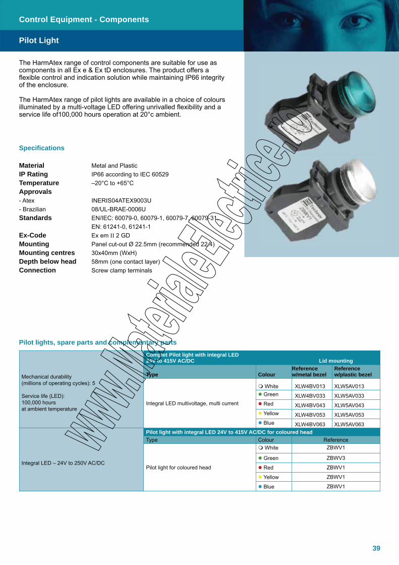
The HarmAtex range of pilot lights are available in a choice of colours illuminated by a multi-voltage LED offering unrivalled flexibility and a service life of100,000 hours operation at 20°c ambient.
Specifications
Material Metal and PlasticIP Rating IP66 according to IEC 60529Temperature –20°C to +65°CApprovals - Atex INERIS04ATEX9003U- Brazilian 08/UL-BRAE-0006UStandards EN/IEC: 60079-0, 60079-1, 60079-7, 60079-31, EN: 61241-0, 61241-1Ex-Code Ex em II 2 GDMounting Panel cut-out Ø 22.5mm (recommended 22.4)Mounting centres 30x40mm (WxH)Depth below head 58mm (one contact layer)Connection Screw clamp terminals
Control Equipment - Components
Mechanical durability (millions of operating cycles): 5
Service life (LED): 100,000 hours at ambient temperature
Complet Pilot light with integral LED 24V to 415V AC/DC Lid mounting
Type ColourReference w/metal bezel
Reference w/plastic bezel
Integral LED multivoltage, multi current
White XLW4BV013 XLW5AV013 Green XLW4BV033 XLW5AV033 Red XLW4BV043 XLW5AV043 Yellow XLW4BV053 XLW5AV053 Blue XLW4BV063 XLW5AV063
Integral LED – 24V to 250V AC/DC
Pilot light with integral LED 24V to 415V AC/DC for coloured headType Colour Reference
Pilot light for coloured head
White ZBWV1
Green ZBWV3
Red ZBWV1
Yellow ZBWV1
Blue ZBWV1
Pilot lights, spare parts and complementary parts
Pilot Light
40
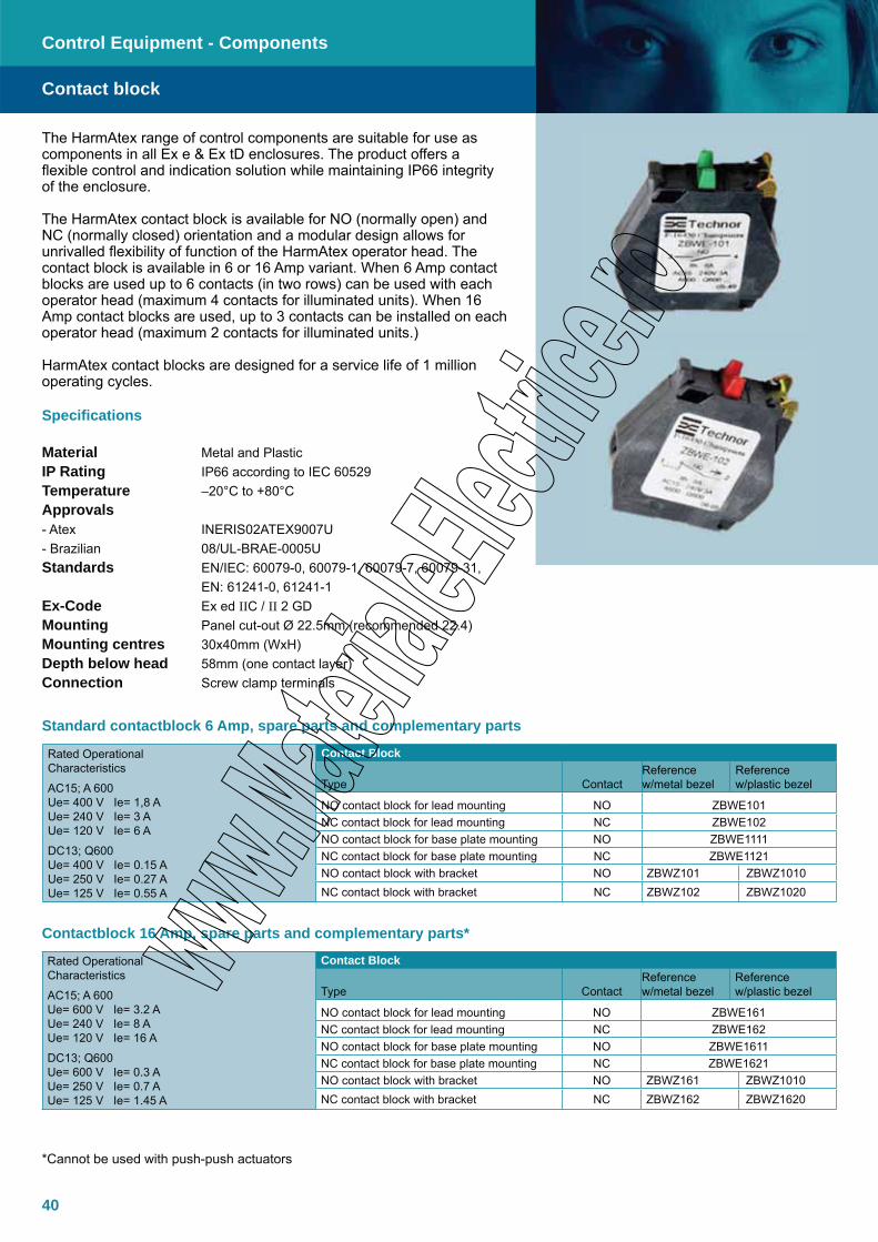
The HarmAtex range of control components are suitable for use as components in all Ex e & Ex tD enclosures. The product offers a flexible control and indication solution while maintaining IP66 integrity of the enclosure.
The HarmAtex contact block is available for NO (normally open) and NC (normally closed) orientation and a modular design allows for unrivalled flexibility of function of the HarmAtex operator head. The contact block is available in 6 or 16 Amp variant. When 6 Amp contact blocks are used up to 6 contacts (in two rows) can be used with each operator head (maximum 4 contacts for illuminated units). When 16 Amp contact blocks are used, up to 3 contacts can be installed on each operator head (maximum 2 contacts for illuminated units.)
HarmAtex contact blocks are designed for a service life of 1 million operating cycles.
Specifications
Material Metal and PlasticIP Rating IP66 according to IEC 60529Temperature –20°C to +80°CApprovals - Atex INERIS02ATEX9007U- Brazilian 08/UL-BRAE-0005UStandards EN/IEC: 60079-0, 60079-1, 60079-7, 60079-31, EN: 61241-0, 61241-1Ex-Code Ex ed IIC / II 2 GDMounting Panel cut-out Ø 22.5mm (recommended 22.4)Mounting centres 30x40mm (WxH)Depth below head 58mm (one contact layer)Connection Screw clamp terminals
Rated Operational Characteristics
AC15; A 600 Ue= 400 V Ie= 1,8 A Ue= 240 V Ie= 3 A Ue= 120 V Ie= 6 A
DC13; Q600 Ue= 400 V Ie= 0.15 A Ue= 250 V Ie= 0.27 A Ue= 125 V Ie= 0.55 A
Contact Block
Type ContactReference w/metal bezel
Reference w/plastic bezel
NO contact block for lead mounting NO ZBWE101NC contact block for lead mounting NC ZBWE102NO contact block for base plate mounting NO ZBWE1111NC contact block for base plate mounting NC ZBWE1121NO contact block with bracket NO ZBWZ101 ZBWZ1010NC contact block with bracket NC ZBWZ102 ZBWZ1020
Standard contactblock 6 Amp, spare parts and complementary parts
Contact block
Control Equipment - Components
Rated Operational Characteristics
AC15; A 600 Ue= 600 V Ie= 3.2 A Ue= 240 V Ie= 8 A Ue= 120 V Ie= 16 A
DC13; Q600 Ue= 600 V Ie= 0.3 A Ue= 250 V Ie= 0.7 A Ue= 125 V Ie= 1.45 A
Contact Block
Type ContactReference w/metal bezel
Reference w/plastic bezel
NO contact block for lead mounting NO ZBWE161NC contact block for lead mounting NC ZBWE162NO contact block for base plate mounting NO ZBWE1611NC contact block for base plate mounting NC ZBWE1621NO contact block with bracket NO ZBWZ161 ZBWZ1010NC contact block with bracket NC ZBWZ162 ZBWZ1620
*Cannot be used with push-push actuators
Contactblock 16 Amp, spare parts and complementary parts*
41
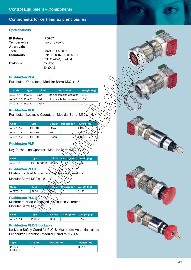
Pushbutton PLBPushbutton Lockable Operators - Modular Barrel M32 x 1,5.
Code Type Colour Description Weight (kg)A.0276.14 PLB 10 Black 0.180
A.0276.15 PLB 20 Red 0.180
A.0276.16 PLB 30 Green 0.180
Components for certified Ex d enclosures
Control Equipment – Components
Pushbutton PLA Pushbutton Operators - Modular Barrel M32 x 1.5.
Code Type Colour Description Weight (kg)A.0276.11 PLA 10 Black Start pushbutton operator 0.150
A.0276.12 PLA 20 Red Stop pushbutton operator 0.150
A.0276.13 PLA 30 Green 0.150
Pushbutton PLC-SMushroom-Head Mantained Pushbutton Operator - Modular Barrel M32 x 1,5.
Code Type Colour Description Weight (kg)A.0276.18 PLC-S Red 0.150
Pushbutton PLC-S Lockable Lockable Safety Guard for PLC-S: Mushroom-Head Maintained Pushbutton Operator - Modular Barrel M32 x 1,5.
Type Colour Description Weight (kg)PLC-S Lockable
Red 0.210
Pushbutton PLF
Key Pushbutton Operator - Modular Barrel M32 x 1,5.
Code Type Colour Description Weight (kg)A.0279.11 PLF 10-01/12 Black 0.200
Pushbutton PLC-IMushroom-Head Momentary Pushbutton Operator -
Modular Barrel M32 x 1,5.
Code Type Colour Description Weight (kg)A.0276.17 PLC-I Red 0.150
Specifications
IP Rating IP66-67 Temperature –50°C to +60°CApprovals - Atex IMQ09ATEX019UStandards EN/IEC: 60079-0, 60079-1 EN: 61241-0, 61241-1Ex-Code Ex d IIC Ex tD A21
42
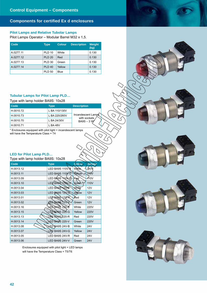
Components for certified Ex d enclosures
Control Equipment – Components
Code Type Colour Description Weight (kg)
A.0277.11 PLD 10 White 0.130
A.0277.12 PLD 20 Red 0.130
A.0277.13 PLD 30 Green 0.130
A.0277.14 PLD 40 Yellow 0.130
PLD 50 Blue 0.130
Tubular Lamps for Pilot Lamp PLD…Type with lamp holder BA9S: 10x28 Code Type DescriptionH.0010.72 L BA 110/130V
Incandescent Lamps with sockets BA9S – 3 W*
H.0010.73 L BA 220/260V
H.0010.70 L BA 24/30V
H.0010.71 L BA 48V
* Enclosures equipped with pilot light + incandescent lamps will have the Temperature Class = T4
LED for Pilot Lamp PLD…Type with lamp holder BA9S: 10x28Code Type Colour VoltageH.0013.12 LED BA9S 110V-B White 110V
H.0013.11 LED BA9S 110V-G Yellow 110V
H.0013.09 LED BA9S 110V-R Red 110V
H.0013.10 LED BA9S 110V-V Green 110V
H.0013.04 LED BA9S 12V-B White 12V
H.0013.03 LED BA9S 12V-G Yellow 12V
H.0013.01 LED BA9S 12V-R Red 12V
H.0013.02 LED BA9S 12V-V Green 12V
H.0013.16 LED BA9S 220-B White 220V
H.0013.15 LED BA9S 220-G Yellow 220V
H.0013.13 LED BA9S 220-R Red 220V
H.0013.14 LED BA9S 220-V Green 220V
H.0013.08 LED BA9S 24V-B White 24V
H.0013.07 LED BA9S 24V-G Yellow 24V
H.0013.05 LED BA9S 24V-R Red 24V
H.0013.06 LED BA9S 24V-V Green 24V
Enclosures equipped with pilot light + LED lamps will have the Temperature Class = T5/T6
Pilot Lamps and Relative Tubolar LampsPilot Lamps Operator – Modular Barrel M32 x 1,5.

43
Control Equipment – Components
Components for certified Ex d enclosures
Selector Switches (nominal current AC1-600V) – Modular Barrel M32 x 1,5.Code Type Poles Rating A Weight (kg)A.0542.51 PSRC 120 1 20 0.130
A.0542.52 PSRC 220 2 20 0.160
A.0542.53 PSRC 320 3 20 0.200
A.0542.54 PSRC 420 4 20 0.200
A.0543.51 PSRC 132 1 32 0.200
A.0543.52 PSRC 232 2 32 0.200
A.0543.53 PSRC 332 3 32 0.250
A.0543.54 PSRC 432 4 32 0.250
PSRC – CStep Switches (nominal current AC1-600V) – Modular Barrel M32 x 1,5. Code Type Poles Rating A Weight (kg)A.0545.51 PSRC-C-120 1 20 0.130
A.0545.52 PSRC-C-220 2 20 0.200
A.0545.53 PSRC-C-320 3 20 0.250
PSRC – DChange Over Switches (nominal current AC1-600V) – Modular Barrel M32 x 1,5.Code Type Poles Rating A Weight (kg)A.0544.51 PSRC-D-120 1 20 0.130
A.0544.52 PSRC-D-220 2 20 0.200
A.0544.53 PSRC-D-320 3 20 0.250
Maximum 4 contact blocks for each operatorsCode Type Description Weight (kg)A.0280.01 ELC - NO NO FOR Pushbutton
operator0.006
A.0280.02 ELC - NC NC FOR Pushbutton operator
0.006
ELC – NC/NO NC+NO Contact block combintation
ELC – NO/NC NO+NC Contact block combination

44
45
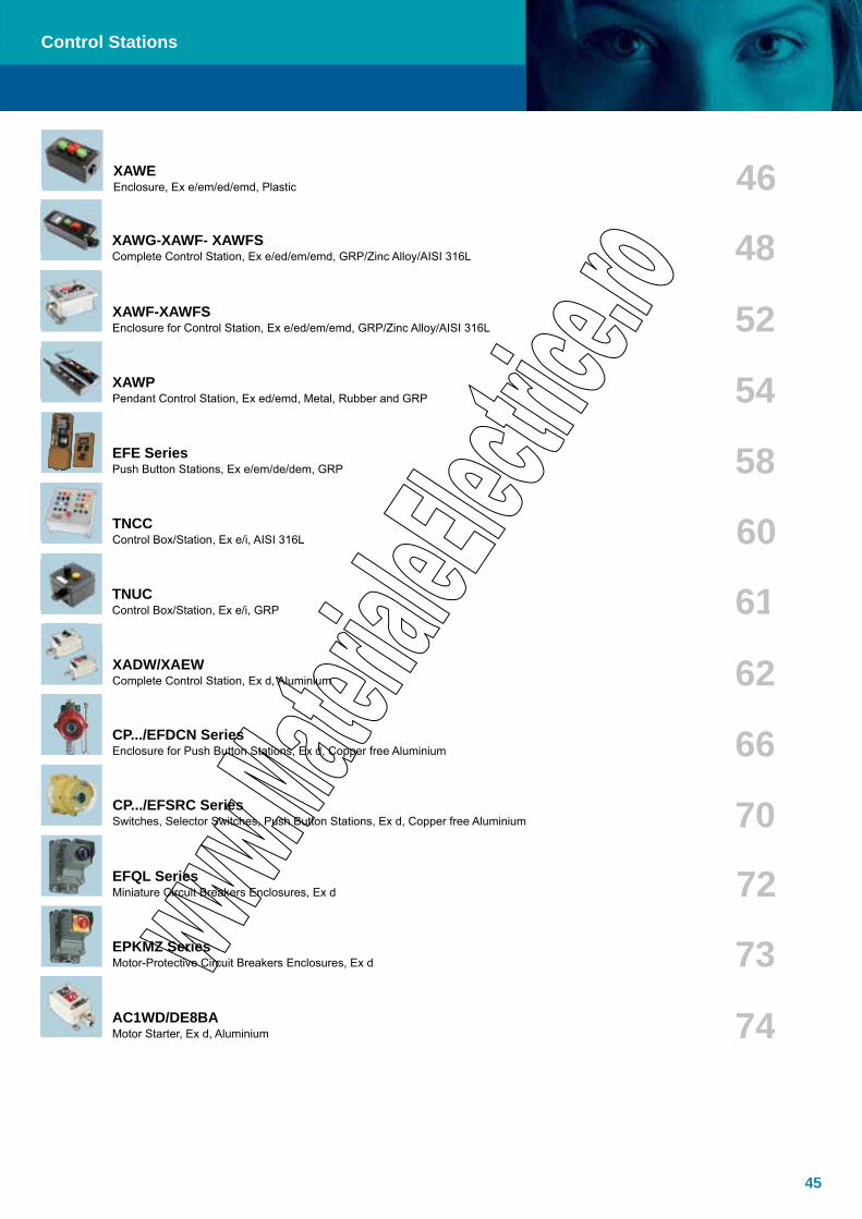
XAWG-XAWF- XAWFSComplete Control Station, Ex e/ed/em/emd, GRP/Zinc Alloy/AISI 316L
XAWEEnclosure, Ex e/em/ed/emd, Plastic
Control Stations
XAWPPendant Control Station, Ex ed/emd, Metal, Rubber and GRP
XAWF-XAWFSEnclosure for Control Station, Ex e/ed/em/emd, GRP/Zinc Alloy/AISI 316L
TNUCControl Box/Station, Ex e/i, GRP
TNCCControl Box/Station, Ex e/i, AISI 316L
AC1WD/DE8BAMotor Starter, Ex d, Aluminium
EFQL SeriesMiniature Circuit Breakers Enclosures, Ex d
EPKMZ SeriesMotor-Protective Circuit Breakers Enclosures, Ex d
EFE SeriesPush Button Stations, Ex e/em/de/dem, GRP
XADW/XAEWComplete Control Station, Ex d, Aluminium
CP.../EFDCN SeriesEnclosure for Push Button Stations, Ex d, Copper free Aluminium
CP.../EFSRC SeriesSwitches, Selector Switches, Push Button Stations, Ex d, Copper free Aluminium
46
48
52
54
58
60
61
62
66
70
72
73
74
46
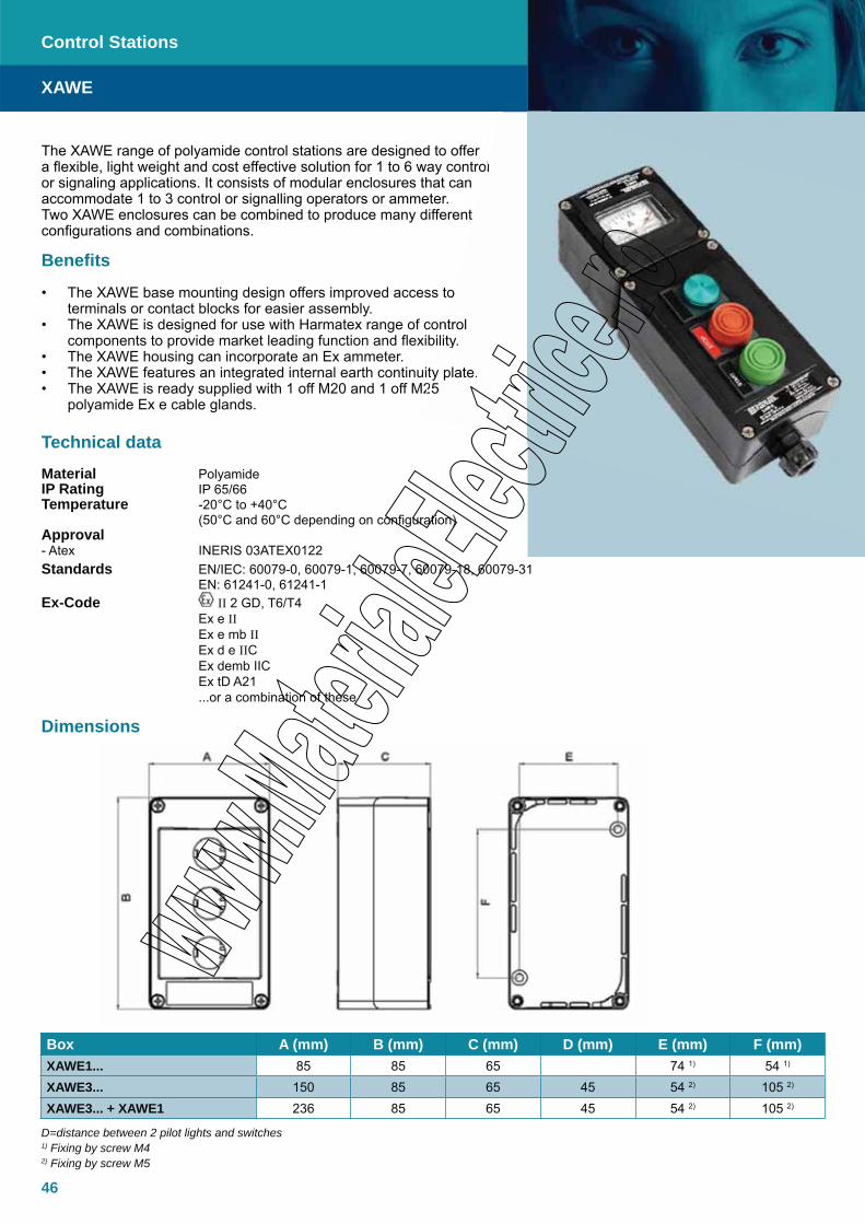
XAWE
Control Stations
Technical data
Material PolyamideIP Rating IP 65/66Temperature -20°C to +40°C (50°C and 60°C depending on configuration)Approval - Atex INERIS 03ATEX0122Standards EN/IEC: 60079-0, 60079-1, 60079-7, 60079-18, 60079-31 EN: 61241-0, 61241-1Ex-Code II 2 GD, T6/T4 Ex e II Ex e mb II Ex d e IIC Ex demb IIC Ex tD A21 ...or a combination of these
The XAWE range of polyamide control stations are designed to offer a flexible, light weight and cost effective solution for 1 to 6 way control or signaling applications. It consists of modular enclosures that can accommodate 1 to 3 control or signalling operators or ammeter. Two XAWE enclosures can be combined to produce many different configurations and combinations.
Benefits
The XAWE base mounting design offers improved access to • terminals or contact blocks for easier assembly.The XAWE is designed for use with Harmatex range of control • components to provide market leading function and flexibility.The XAWE housing can incorporate an Ex ammeter.• The XAWE features an integrated internal earth continuity plate.• The XAWE is ready supplied with 1 off M20 and 1 off M25 • polyamide Ex e cable glands.
Box A (mm) B (mm) C (mm) D (mm) E (mm) F (mm)XAWE1... 85 85 65 74 1) 54 1)
XAWE3... 150 85 65 45 54 2) 105 2)
XAWE3... + XAWE1 236 85 65 45 54 2) 105 2)
D=distance between 2 pilot lights and switches1) Fixing by screw M42) Fixing by screw M5
ol
o
ntrol lity.
ty plate.25
Dimensions
47
XAWE
Control Stations
Order InformationFunction Labels (pushbutton color), contact function Insulated box and unit1 pushbutton, spring return Start (green), 1NO XAWE101 pushbutton, spring return Stop (red), 1NC XAWE111 mushroom pushbutton Ø40 mm, spring return
Stop (red), 1NC XAWE16
1 mushroom pushbutton Ø40 mm, latching turn to release
Stop (red), 1NC XAWE17
1 selector switch, 2 positions stay put Start/Stop, 1NO XAWE132 pushbuttons, spring return Start (green), 1NO - Stop (red), 1NC XAWE213 pushbutton, spring return Forward (green), 1NO - Stop (red), 1NC XAWE311 pilot light, 2 pushbuttons, spring return
Red light unit 24-415V AC/DCStart (green), 1NO - Stop (red), 1NC
XAWE34
1 ammeter XAWE2812
Function Terminal functions Insulated box and unit5 terminals 3P + N + E XAWE9104
Function Cable gland (number and type) Insulated box and unit1 pushbutton 1 cable gland M20 + 1 plug M20 XAWE1012 pushbuttons 1 cable gland M20 + 1 plug and 1 cable gland M25 + 1 plug XAWE3023 pushbuttons 1 cable gland M20 + 1 plug and 1 cable gland M25 + 1 plug XAWE303
M20 for cable Ø8 to Ø13 mm, M25 for cable Ø13 to Ø16 mm.
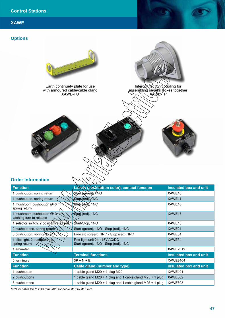
Options
Earth continuety plate for use with armoured cable/cable gland
XAWE-PU
Interconnection coupling for assembling several boxes together
XAWE-TP
48
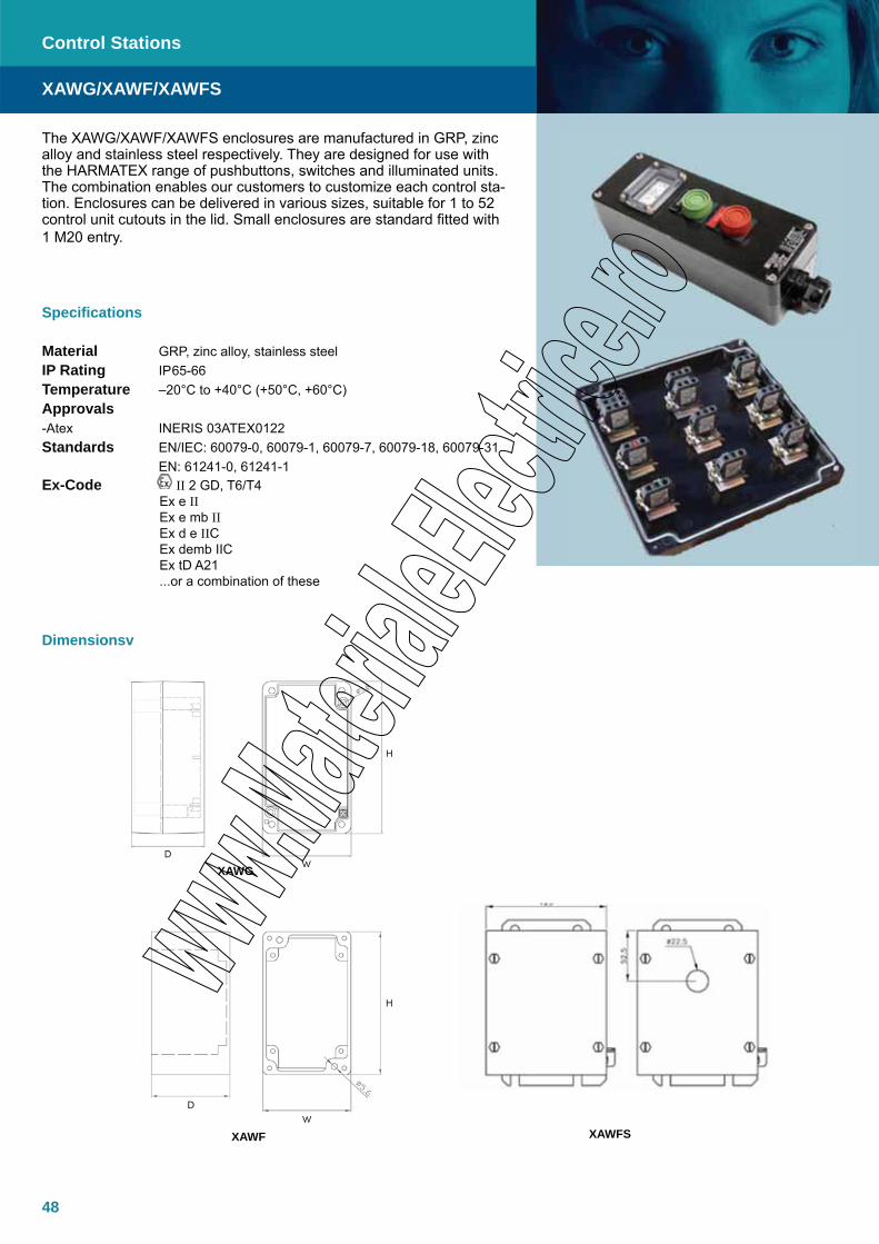
The XAWG/XAWF/XAWFS enclosures are manufactured in GRP, zinc alloy and stainless steel respectively. They are designed for use with the HARMATEX range of pushbuttons, switches and illuminated units. The combination enables our customers to customize each control sta-tion. Enclosures can be delivered in various sizes, suitable for 1 to 52 control unit cutouts in the lid. Small enclosures are standard fitted with 1 M20 entry.
Specifications
Material GRP, zinc alloy, stainless steelIP Rating IP65-66Temperature –20°C to +40°C (+50°C, +60°C)Approvals -Atex INERIS 03ATEX0122Standards EN/IEC: 60079-0, 60079-1, 60079-7, 60079-18, 60079-31 EN: 61241-0, 61241-1Ex-Code II 2 GD, T6/T4 Ex e II Ex e mb II Ex d e IIC Ex demb IIC Ex tD A21 ...or a combination of these
Dimensionsv
XAWG
XAWF XAWFS
Control Stations
XAWG/XAWF/XAWFS
W
H
D
W
H
D

49
Empty insulated enclosures (GRP)
External dimensions in mm Max. nbr. of Ø22.2 cutout
Window for de-vice Ø48mm
Enclosure reference with cutouts
Enclosure reference witout cutouts
Weight kgW H D
85 146 70 1 - XAWG201 XAWG2C 0.5402 - XAWG208 XAWG2C 0.540- 1 XAWG208 XAWG2C 0.540
85 226 70 3 - XAWG303 XAWG3C 0.6702 1 XAWG308 XAWG3C 0.670
85 281 70 4 - XAWG504 XAWG5C 0.9305 - XAWG505 XAWG5C 0.930
Empty metal enclosures (zink alloy)
External dimensions in mm Max. nbr. of Ø22.2 cutout
Window for de-vice Ø48mm
Enclosure reference with cutouts
Enclosure reference witout cutouts
Weight kgW H D
80 80 77 1 XAWF101 XAWF1C 0.61080 130 77 2 XAWF202 XAWF2C 0.820
- 1 XAWF208 XAWF2C 0.82080 175 77 3 XAWF303 XAWF3C 1.150
2 1 XAWF308 XAWF3C 1.15080 220 77 4 XAWF404 XAWF4C 1.40080 310 77 6 XAWF606 XAWF6C 1.900
Empty stainless steel enclosures
External dimensions in mm Max. nbr. of Ø22.2 cutout
Window for de-vice Ø48mm
Enclosure reference with cutouts
Enclosure reference witout cutouts
Weight kgW H D
125 110 82 1 - XAWFS101 XAWFS1C 1.000125 150 82 2 - XAWFS202 XAWFS2C 1.200
- 1 XAWFS208 - 1.200125 195 82 3 - XAWFS303 XAWFS3C 1.400
2 1 XAWFS308 - 1.400125 240 82 4 - XAWFS404 XAWFS4C 1.600
3 1 XAWFS408 - 1.600125 295 82 5 - XAWFS505 XAWFS5C 1.900
4 1 XAWFS508 - 1.900125 330 82 6 - XAWFS606 XAWFS6C 2.100
5 1 XAWFS608 - 2.100
Cable glands (maximum possible per side)
SIDE A/C
M20 M25 M32 References
1 1 - XAWG2...
1 1 - XAWG3...
1 1 - XAWG5...
1 1 1 XAWF1-FS1...
1 1 1 XAWF2-FS2...
1 1 1 XAWF3-FS3...
1 1 1 XAWF4-FS4/5...
1 1 1 XAWF6-FS6...
Control stations enclosures Ex e
Control Stations
XAWG/XAWF/XAWFS

50
Empty insulated enclosures
External dimensions in mmW H D
Max. nbr. of terminal blocks to be fitted
Max terminal capacity in
mm2
Enclosure reference with cutouts
Enclosure reference witout cutouts
Weight kg
85 146 70 10 0 to 4 XAWG9204 XAWG92C 0.4506 10 XAWG9210 XAWG92C 0.450
85 226 70 15 0 to 4 XAWG9304 XAWG93C 0.70010 10 XAWG9310 XAWG93C 0.700
85 281 70 25 0 to 4 XAWG9504 XAWG95C 0.80020 10 XAWG9510 XAWG95C 0.800
Empty metal enclosuresExternal dimensions in mm
W H DMax. nbr. of Ø22,2
cutoutMax terminal capacity in
mm2
Enclosure reference with cutouts
Enclosure reference witout cutouts
Weight kg
80 130 77 7 0 to 4 XAWF9204 XAWF92C 0.810- 10 XAWF9210 XAWF92C 0.810
80 175 77 15 0 to 4 XAWF9304 XAWF93C 1.15015 10 XAWF9310 XAWF93C 1.150
80 220 77 20 0 to 4 XAWF9404 XAWF94C 1.38020 10 XAWF9410 XAWF94C 1.380
80 310 77 30 0 to 4 XAWF9604 XAWF96C 1.90030 10 XAWF9610 XAWF96C 1.900
Empty stainless steel enclosuresExternal dimensions in mm
W H DMax. nbr. of Ø22,2
cutoutMax terminal capacity in
mm2
Enclosure reference with cutouts
Enclosure reference witout cutouts
Weight kg
90 130 77 7 0 to 4 XAWFS9204 XAWFS92C 1.200- 10 XAWFS9210 - 1.200
90 175 77 15 0 to 4 XAWFS9304 XAWFS93C 1.40015 10 XAWFS9310 - 1.400
90 220 77 20 0 to 4 XAWFS9404 XAWFS94C 1.60020 10 XAWFS9410 - 1.600
90 275 77 25 0 to 4 XAWFS9504 XAWFS95C 1.90025 10 XAWFS9510 - 1.900
90 310 77 30 0 to 4 XAWFS9504 XAWFS96C 2.10030 10 XAWFS9510 - 2.100
Cable glands (maximum possible per side)
SIDE A/C
M20 M25 M32 References
1 1 - XAWG92...
1 1 - XAWG93...
1 1 - XAWG95...
1 1 1 XAWF92-FS92...
1 1 1 XAWF93-FS93...
1 1 1 XAWF94-FS94/5...
1 1 1 XAWF96-FS96...
Cable glands (maximum possible per side)SIDE B/D
M20 M25 M32 References
2 2 - XAWG92...
4 4 - XAWG93...
5 5 - XAWG95...
2 1 1 XAWF92-FS92...
2 3 2 XAWF93-FS93...
5 4 3 XAWF94-FS94/5...
6 5 4 XAWF96-FS96...
Junction box enclosures Ex e
Control Stations
XAWG/XAWF/XAWFS
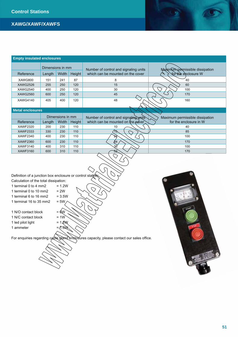
51
Empty insulated enclosures
Dimensions in mm Number of control and signaling units which can be mounted on the cover
Maximum permissible dissipation for the enclosure WReference Length Width Height
XAWG800 151 241 87 8 40XAWG2526 255 250 120 15 60XAWG2540 400 250 120 30 100XAWG2560 600 250 120 45 170
XAWG4140 405 400 120 48 160
Metal enclosures
Dimensions in mm Number of control and signaling units which can be mounted on the cover
Maximum permissible dissipation for the enclosure in WReference Length Width Height
XAWF2320 200 230 110 10 40XAWF2333 330 230 110 15 85XAWF2340 400 230 110 24 100
XAWF2360 600 230 110 34 170XAWF3140 400 310 110 36 100XAWF3160 600 310 110 52 170
Definition of a junction box enclosure or control station:Calculation of the total dissipation:1 terminal 0 to 4 mm2 = 1.2W1 terminal 0 to 10 mm2 = 2W1 terminal 6 to 16 mm2 = 3.5W1 terminal 16 to 35 mm2 = 5W
1 N/O contact block = 0W1 N/C contact block = 1W1 led pilot light = 1.5W1 ammeter = 1.5W
For enquiries regarding cable gland enclosures capacity, please contact our sales office.
Control Stations
XAWG/XAWF/XAWFS

52
The XAWG/XAWF/XAWFS range of complete control stations are manufactured in GRP, zinc alloy or stainless steel respectively. The enclosure can accommodate 1-3 control or signaling operators or ammeter and come delivered with plastic Ex e cable glands as standard.
Specifications
Material GRP, zinc alloy or stainless steelIP Rating IP65–66Temperature –20°C to +40°C (+50°C, +60°C) Approvals - Atex INERIS 03ATEX0122Standards EN/IEC: 60079-0, 60079-1, 60079-7, 60079-18, 60079-31 EN: 61241-0, 61241-1Ex-Code II 2 GD, T6/T4 Ex e II Ex e mb II Ex d e IIC Ex demb IIC Ex tD A21 ...or a combination of these
Pushbutton Station
Function
Label (pushbutton colour) and contact
function
Insulated station with
insulated unit
Metal station with metal
unit
Stainless steel station with metal unit
1 pushbutton with spring return Start (green) 1 NO XAWG10 XAWF10 XAWFS10
1 pushbutton with spring return Stop (red) 1 NC XAWG11 XAWF11 XAWFS11
1 pushbutton, mushroom head Ø40 mm, with spring return Stop (red) 1 NC XAWG16 XAWF16 XAWFS16
1 pushbutton, mushroom head Ø40 mm, latching turn to release Stop (red) 1 NC XAWG17 XAWF17 XAWFS17
1 selector switch 2 positions stay put Start/Stop 1 NO XAWG13 XAWF13 XAWFS13
2 pushbuttons with spring return Start (green) 1 NO Stop (red) 1 NC
XAWG21 XAWF21 XAWFS21
3 pushbuttons with spring return Forward (green) 1 NO Stop (red) 1 NC
Reverse (green) 1 NO
XAWG31 XAWF31 XAWFS31
1 pilot light, 2 pushbuttons with spring return Red light unit 24-250V AC-DC
Start (green) 1 NO Stop (red) 1 NC
XAWG34 XAWF34 XAWFS34
Measurement Station
Function
Labels (pushbutton colour) and contact
function
Insulated station with
insulated unit
Metal station with metal
unit
Stainless steel station with metal unit
1 ammeter XAWG2812 XAWF2812 XAWFS2812
1 ammeter, 1 selector switch, 2 positions stay put Start/Stop 1 NO XAWG3812 XAWF3812 XAWFS3812
1 ammeter, 2 pushbuttons, spring return Start (green) 1 NO Stop (red) 1 NC
XAWG382 XAWF482 XAWFS482
Cable gland: XAWG1... XAWG2... plastic cable gland for cable Ø 8 to 13 mm XAWG3... plastic cable gland for cable Ø 13 to 19 mm XAWF(S)1... XAWF(S)2... XAWF(S)3... brass cable gland for cable Ø 8.5 to 16 mm XAWF(S)4... brass cable gland for cable Ø 12 to 20.5 mm For control unit please see our Harmatex documentationThe ammeter is of the current transformer type, for use with a currrent transformer of 1 or 5 amp secondary (C.T. not supplied). Please state required ammeter motor scale and C.T. secondary current when ordering.Note: For the insulated station the contact blocks are mounted in the base. For the metal stations, they are mounted on the cover.
XAWF/XAWFS
Control Stations
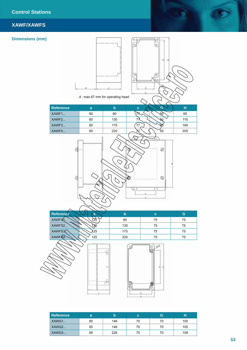
53
Control Stations
XAWF/XAWFS
Reference a b c G HXAWF1... 80 80 77 50 65
XAWF2... 80 130 77 50 115
XAWF3... 80 175 77 50 160
XAWF4... 80 220 77 50 205
Reference a b c GXAWFS1... 125 90 75 75
XAWFS2... 125 130 75 75
XAWFS3... 125 175 75 75
XAWFS4... 125 220 75 75
Reference a b c G HXAWG1... 85 146 70 70 105
XAWG2... 85 146 70 70 105
XAWG3... 85 226 70 70 108
Dimensions (mm)
d : max 67 mm for operating head

54
The XAWP range of pendant control stations is suitable for all kinds of industry but primarily used on cranes. The XAWP range is available with 2, 4, 6 or 8 pushbuttons with up to three contact blocks per operator. Custom double XAWP assemblies can be delivered to provide 12 or 16 way pendant control stations. The XAWP also features an optional double-step actuation mode for dual speed control.
Specifications
Material Metal, Rubber and GRPIP Rating IP65Temperature 20°C to +60°C (without lighting functions) -20°C to +50°C (with lighting functions)Approvals - Atex INERIS 03ATEX0122Standards EN/IEC: 60079-0, 60079-1, 60079-7, 60079-18, 60079-31 EN: 61241-0, 61241-1Mounting Assembly of components only by TECHNORCable entry capacity for Ø10 to Ø22 mm cableConnection Screw clamp terminals From 1 x 0.5 mm² cable to 2 x 1.5 mm² cable (with or without ferrule)Availability Standard version available on catalogue Special version available on request
XAW-P
Dimensions
Control Stations

55
Fitted with interchangeable booted pushbutton, operators with start and emergency stop functions. With labels in yellow blank and cable boot suitable for Ø10 to Ø22mm cable.
Number of way Function Contact blocks mounted on each way Reference Weight Kg
Fitted with interchange-able booted pushbutton, operators with start and emergency stop functions.With labels in yellow blank and cable boot suitable for Ø10 to Ø22mm cable
4
IO
1 N/OFor Direction and Start Functions
1 N/C + 1 N/OFor All Functions
XAWP472
XAWP482
1.320
1.380
6
IO
1 N/OFor Direction and Start Functions
1 N/C + 1 N/OFor All Functions
XAWP672
XAWP682
1.650
1.690
8
IO
1 N/OFor Direction and Start Functions
1 N/C + 1 N/OFor All Functions
XAWP872
XAWP882
2.000
2.250
1 N/CFor Stop Function
1 N/CFor Stop Function
1 N/CFor Stop Function
Fitted with interchangeable booted operators and cable boot suitable for Ø10 to Ø22mm
Number of way Function Contact blocks mounted on each way Reference Weight Kg
21 N/O
1 N/C + 1 N/O
XAWP271
XAWP281
0.940
1.000
41 N/O
1 N/C + 1 N/O
XAWP471
XAWP481
1.290
1.400
61 N/O
1 N/C + 1 N/O
XAWP671
XAWP681
1.650
1.800
Stations
XAW-P
Control Stations
56
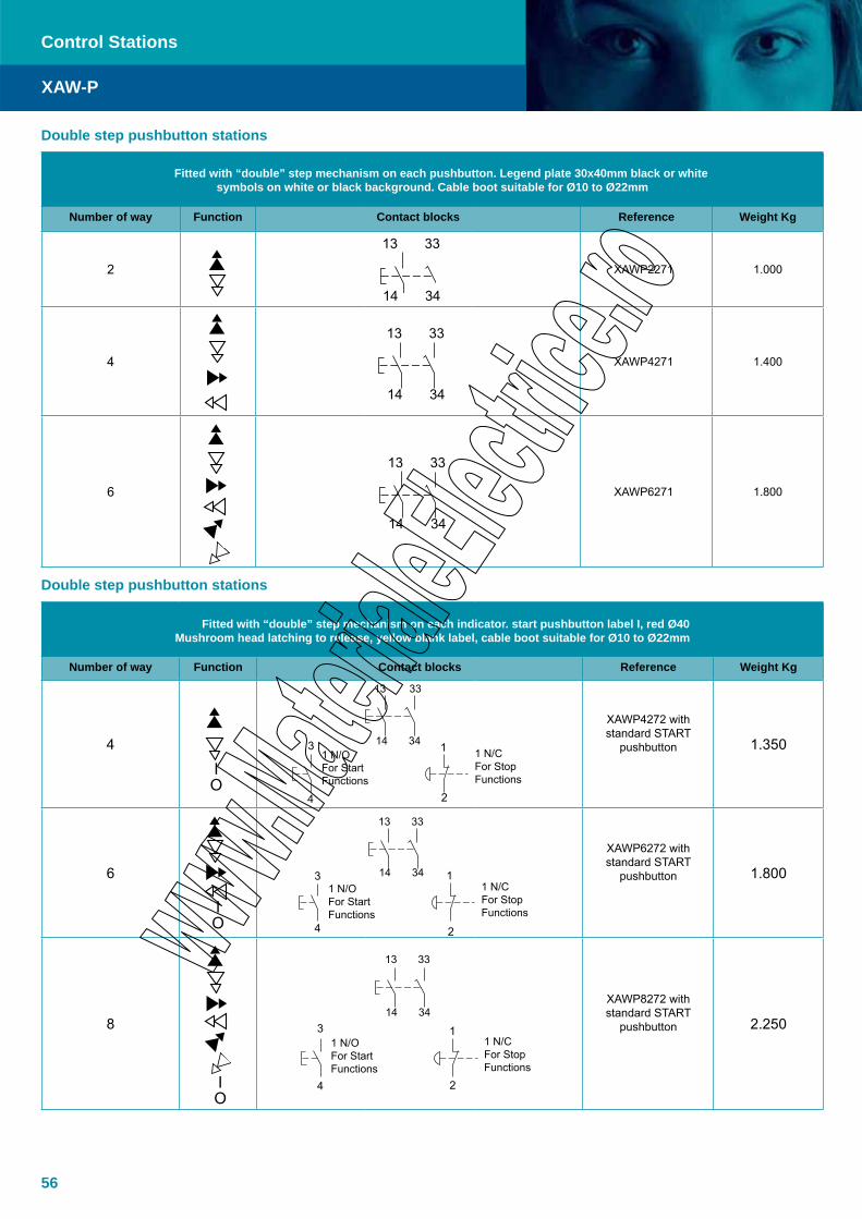
Fitted with “double” step mechanism on each pushbutton. Legend plate 30x40mm black or white symbols on white or black background. Cable boot suitable for Ø10 to Ø22mm
Number of way Function Contact blocks Reference Weight Kg
2 XAWP2271 1.000
4 XAWP4271 1.400
6 XAWP6271 1.800
13 33
14 34
13 33
14 34
13 33
14 34
Fitted with “double” step mechanism on each indicator. start pushbutton label I, red Ø40 Mushroom head latching to release, yellow blank label, cable boot suitable for Ø10 to Ø22mm
Number of way Function Contact blocks Reference Weight Kg
4
XAWP4272 with standard START
pushbutton 1.350
6
XAWP6272 with standard START
pushbutton 1.800
8
XAWP8272 with standard START
pushbutton 2.250
Double step pushbutton stations
IO
IO
IO
13 33
14 34
13 33
14 34
13 33
14 34
1 N/OFor Start Functions
1 N/CFor Stop Functions
3 1
4 2
1 N/OFor Start Functions
1 N/CFor Stop Functions
3 1
4 2
Double step pushbutton stations
XAW-P
Control Stations
1 N/OFor Start Functions
1 N/CFor Stop Functions
3 1
4 2

57
Accessories and spare parts
Type Function Reference
Empty pendant control station for mounting exclusively by TECHNOR
02 buttons XAWP02904 buttons XAWP04906 buttons XAWP06908 buttons XAWP08912 buttons XAWP069D16 buttons XAWP089D
Slow break contact blockN/O ZBWE101N/C ZBWE102
Complete booted pushbutton operator
White (W) XAWP9411Black (B) XAWP9412Green (G) XAWP9413Red (R) XAWP9414
Selector switches (Stayput)
2 pos. Black+NO
XBW5AD21
3 pos. Black+2NO
XBW5AD33
Pilot light + head (-24V to 415V AC-DC)
White XLW5AV013Green XLW5AV033Red XLW5AV043Yellow XLW5AV053Blue XLW5AV063
Blank plug XAWZ3Double step push-buttons(use only with ZBWE101 contact blocks)
White (W) XAWP9421Black (B) XAWP9422
Emergency Mushroom head (Ø40) Red+NC ZA2BS54 + ZBWE102
Emergency Mushroom head (Ø30) Red+NC ZA2BS44 + ZBWE102
ARROW for Double step pushbutton
ARROW for Single step pushbutton
UP ZBWY4953 UP ZBWY4951
DOWN ZBWY2956 DOWN ZBWY2954
RIGHT ZBWY4903 RIGHT ZBWY4901
LEFT ZBWY2906 LEFT ZBWY2904
FORWARD ZBWY4965 FORWARD ZBWY4963
REVERSE ZBWY2968 REVERSE ZBWY2966
FAST UP ZBWY4952
FAST DOWN ZBWY2955
FAST RIGHT ZBWY4902
FAST LEFT ZBWY2905
FAST FORWARD ZBWY4964
FAST REVERSE ZBWY2967
I ZBWY4980
O ZBWY2931
O - I ZBWY2178
I - II ZBWY2179
I - O - II ZBWY2186
EMERGENCY STOP
ZBWY2330
ZBWE101
XAWP9411
XLW5AV033
XAW-P
Control Stations

58
Specifications
Material Resin GRP (Glass Fiber Reinforced Polyester)
IP Rating IP65-66Temperature -50°C to 60°C
Approvals- Atex- GOST
INERIS 04ATEX0035GOST Certificate
Standards EN/IEC: 60079-0, 60079-1, 60079-7, 60079-18,
EN: 61241-0, 61241-1Ex-code II 2 GD
Ex e II T6 IP65 T85°CEx e II T4 IP65 T135°CEx emb II T6 IP65 T85°CEx emb II T4 IP65 T135°CEx de IIC T6 IP65 T85°CEx de IIC T4 IP65 T135°CEx demb IIC T6 IP65 T85°CEx demb IIC T4 IP65 T135°C
Type of protection depends on what components are fitted.According to European Directive 94/9/EC (ATEX)For Zone 1 / Zone 2, Zone 21 / Zone 22
Lid / Door gasket Silicone sealSurface treatment Black colourEarthing Earth connections are made via EEx e certified terminalsDrain plug The enclosures can be equipped with drain and breather devices ECR-1; ECR-2 type.Entries thread Metric pitch 1.5, ANSI B1.20.1 NPT, UNI 6125Standard identification
Identification nameplate is realized in high resistance self-adhesive polyester with thermal transfer inscriptions
Quantity for entries Contact our Technical Department for further informationQuantity for terminals Contact our Technical Department for further informationRated Voltage 690 VRated Current 16 ARated Frequency 48÷62 Hz
Note Captive screws stainless steel madeAvailable only with terminal strip installed
Note The above control station becomes EFEX... if realized in Stainless steel 316L instead of GRP
The EFE range of Control and Signaling Units is based on a standardized range of 10 different sizes of GRP (Glass fibre Reinforced Polyester) Ex e enclosure. The EFE Series can be assembled with accessories including start pushbutton, stop pushbutton with padlocking device, local-remote change-over switch, and ammeter, wired to a terminal rail inside the enclosure.
EFE
Control Stations

59
Control/Signalling Units - Push Button Stations listed in the following table are “not assembled”, they are examples of the possible combinations. The maximum number of control units shown in the table is compatible with our standard labelling system (holder-label).
TYPE DIMENSIONS [mm] Number of Control and Signalling Units Which can be mounted on the Cover
Maximum permissible Dissipation for the Enclosures [W]
EFE 1212-CS 122x120x90 2 10EFE 1222-CS 120x220x90 6 30EFE 1616-CS 160x160x90 4 20EFE 1626-CS 160x260x90 8 40EFE 1636-CS 160x360x90 10 50EFE 2526-CS 255x250x121 16 60EFE 2540-CS 250x400x121 24 100EFE 2560-CS 250x600x121 40 170EFE 4140-CS 405x400x121 42 160
EFE
Control Stations
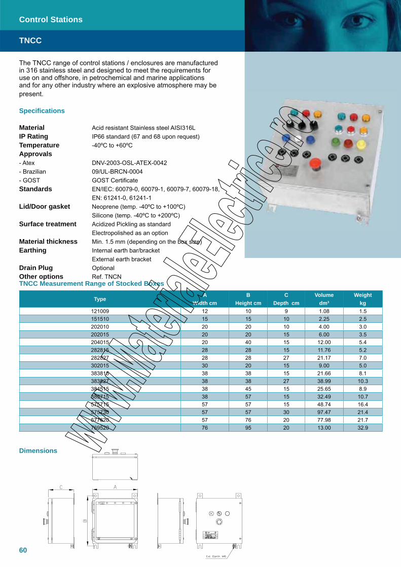
60
The TNCC range of control stations / enclosures are manufactured in 316 stainless steel and designed to meet the requirements for use on and offshore, in petrochemical and marine applications and for any other industry where an explosive atmosphere may be present.
Specifications
Material Acid resistant Stainless steel AISI316LIP Rating IP66 standard (67 and 68 upon request)Temperature -40ºC to +60ºCApprovals - Atex DNV-2003-OSL-ATEX-0042 - Brazilian 09/UL-BRCN-0004- GOST GOST CertificateStandards EN/IEC: 60079-0, 60079-1, 60079-7, 60079-18, EN: 61241-0, 61241-1Lid/Door gasket Neoprene (temp. -40ºC to +100ºC) Silicone (temp. -40ºC to +200ºC)Surface treatment Acidized Pickling as standard Electropolished as an optionMaterial thickness Min. 1.5 mm (depending on the box size)Earthing Internal earth bar/bracket External earth bracketDrain Plug OptionalOther options Ref. TNCN
TypeA
Width cmB
Height cmC
Depth cmVolume
dm3
Weight kg
121009 12 10 9 1.08 1.5151510 15 15 10 2.25 2.5202010 20 20 10 4.00 3.0202015 20 20 15 6.00 3.5204015 20 40 15 12.00 5.4282815 28 28 15 11.76 5.2282827 28 28 27 21.17 7.0302015 30 20 15 9.00 5.0383815 38 38 15 21.66 8.1383827 38 38 27 38.99 10.3384515 38 45 15 25.65 8.9385715 38 57 15 32.49 10.7575715 57 57 15 48.74 16.4575730 57 57 30 97.47 21.4577620 57 76 20 77.98 21.7769520 76 95 20 13.00 32.9
TNCC
Control Stations
TNCC Measurement Range of Stocked Boxes
Dimensions
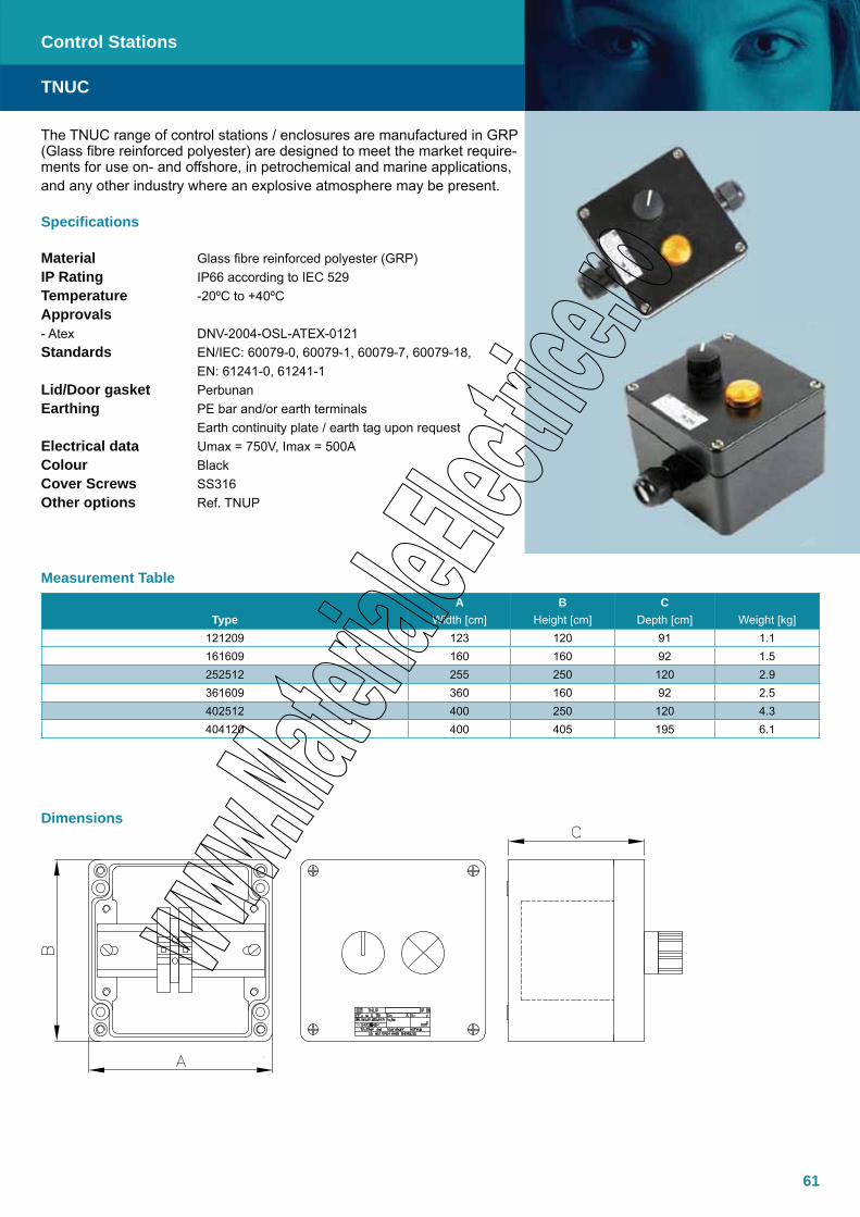
61
The TNUC range of control stations / enclosures are manufactured in GRP (Glass fibre reinforced polyester) are designed to meet the market require-ments for use on- and offshore, in petrochemical and marine applications, and any other industry where an explosive atmosphere may be present.
Specifications
Material Glass fibre reinforced polyester (GRP)IP Rating IP66 according to IEC 529Temperature -20ºC to +40ºCApprovals - Atex DNV-2004-OSL-ATEX-0121Standards EN/IEC: 60079-0, 60079-1, 60079-7, 60079-18, EN: 61241-0, 61241-1Lid/Door gasket PerbunanEarthing PE bar and/or earth terminals Earth continuity plate / earth tag upon requestElectrical data Umax = 750V, Imax = 500AColour BlackCover Screws SS316Other options Ref. TNUP
TNUC
Control Stations
TypeA
Width [cm]B
Height [cm]C
Depth [cm] Weight [kg]121209 123 120 91 1.1161609 160 160 92 1.5252512 255 250 120 2.9361609 360 160 92 2.5402512 400 250 120 4.3404120 400 405 195 6.1
Dimensions
Measurement Table
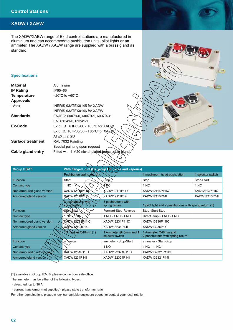
62
The XADW/XAEW range of Ex d control stations are manufactured in aluminium and can accommodate pushbutton units, pilot lights or an ammeter. The XADW / XAEW range are supplied with a brass gland as standard.
Specifications
Material AluminiumIP Rating IP65–66Temperature –20°C to +60°C Approvals - Atex INERIS 03ATEX0145 for XADW INERIS 03ATEX0146 for XAEWStandards EN/IEC: 60079-0, 60079-1, 60079-31 EN: 61241-0, 61241-1Ex-Code Ex d IIB T6 IP65/66 - T85°C for XADW Ex d IIC T6 IP65/66 - T85°C for XAEW ATEX II 2 GDSurface treatment RAL 7032 Painting Special painting upon requestCable gland entry Fitted with 1 M20 nickel-plated brass cable gland
(1) available in Group IIC-T6, please contact our sale office The ammeter may be either of the following types; - direct fed: up to 30 A - current transformer (not supplied): please state transformer ratio For other combinations please check our variable enclosure pages, or contact your local retailer.
Group IIB-T6 With flanged joint (for group IIB gases and vapours)Pushbutton spring return 1 mushroom head pushbutton 1 selector switch
Function Start Stop Stop Stop-Start
Contact type 1 NO 1 NC 1 NC 1 NC
Non armoured gland version XADW12110P11IC XADW12111P11IC XADW12116P11IC XAD12113P11IC
Armoured gland version XADW12110P14I XADW12111P14I XADW12116P14I XADW12113P14I
2 pushbuttons with spring return
3 pushbuttons withspring return 1 pilot light and 2 pushbuttons with spring return (1)
Function Start-Stop Forward-Stop-Reverse Stop -Start-Stop
Contact type 1 NO - 1 NC 1 NO - 1 NC - 1 NO Direct lamp - 1 NO - 1 NC
Non armoured gland version XADW12221P11IC XADW13231P11IC XADW13236P11IC
Armoured gland version XADW12221P14I XADW13231P14I XADW13236P14I
1 Ammeter Ø48mm (1) 1 Ammeter Ø48mm and 1 selector switch
1 Ammeter Ø48mm and 2 pushbuttons with spring return
Function ammeter ammeter - Stop-Start ammeter - Start-Stop
Contact type - 1 NO 1 NO - 1 NC
Non armoured gland version XADW1231P11IC XADW122321P11IC XADW132321P11IC
Armoured gland version XADW1231P14I XADW122321P14I XADW132321P14I
XADW / XAEW
Control Stations
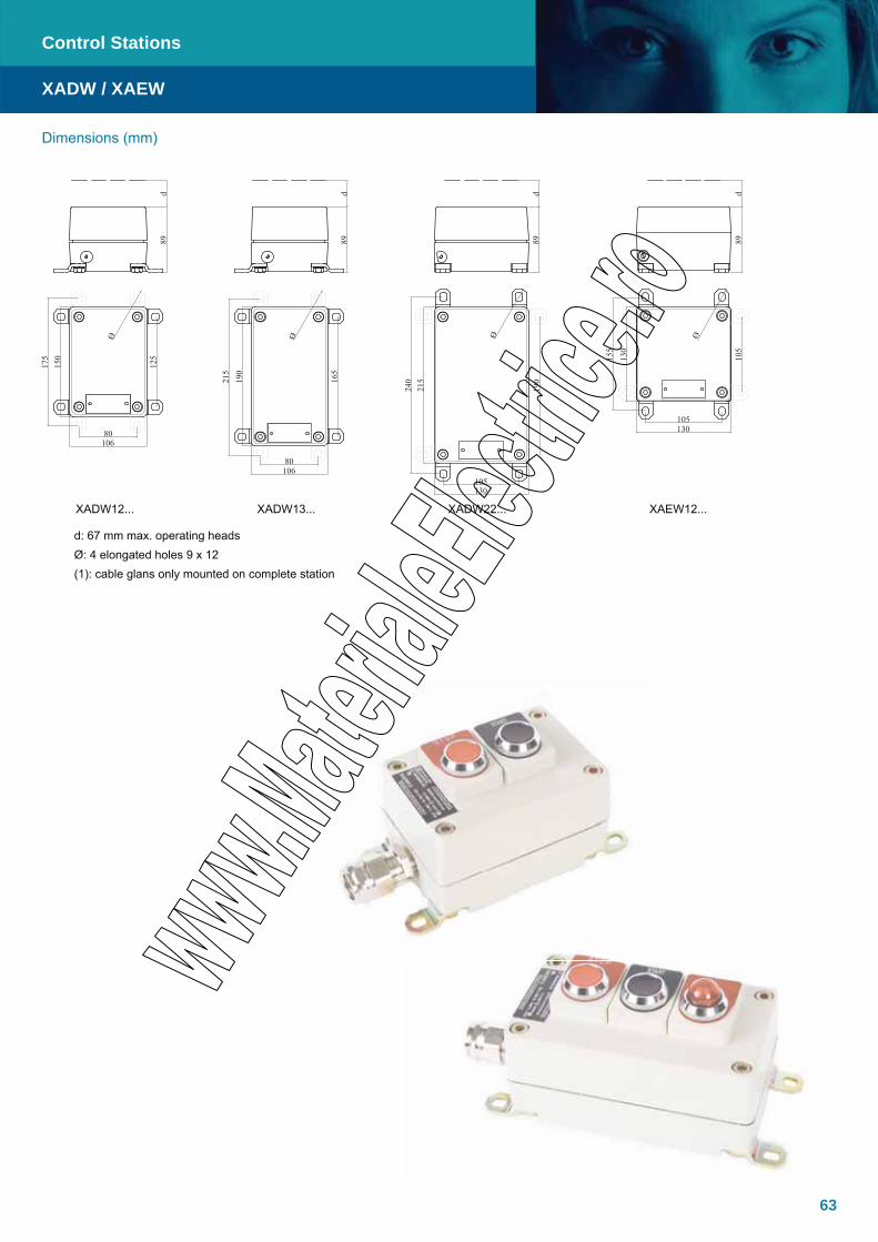
63
Dimensions (mm)
XADW / XAEW
Control Stations
XADW12... XADW13... XADW22... XAEW12...
d: 67 mm max. operating headsØ: 4 elongated holes 9 x 12(1): cable glans only mounted on complete station
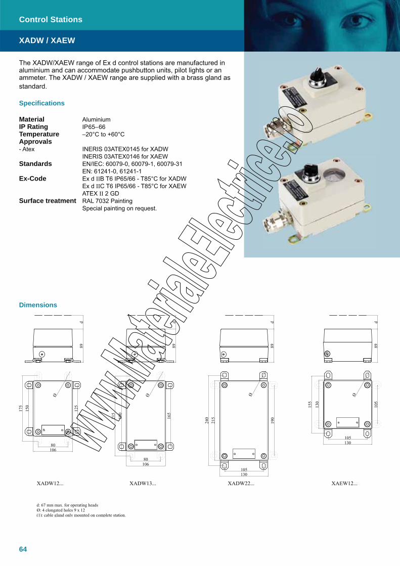
64
The XADW/XAEW range of Ex d control stations are manufactured in aluminium and can accommodate pushbutton units, pilot lights or an ammeter. The XADW / XAEW range are supplied with a brass gland as standard.
Specifications
Material AluminiumIP Rating IP65–66Temperature –20°C to +60°C Approvals - Atex INERIS 03ATEX0145 for XADW INERIS 03ATEX0146 for XAEWStandards EN/IEC: 60079-0, 60079-1, 60079-31 EN: 61241-0, 61241-1Ex-Code Ex d IIB T6 IP65/66 - T85°C for XADW Ex d IIC T6 IP65/66 - T85°C for XAEW ATEX II 2 GDSurface treatment RAL 7032 Painting Special painting on request.
XADW / XAEW
Control Stations
Dimensions

65
XADW / XAEW
Control Stations
Group IIC-T6With Circular joint (for group IIC gases and vapours)
M20 entries Positions Reference
1 operator or pilot light
1 A XAEW12101
2 A - C XAEW12102
2 L - M XAEW12103
2 operators or pilot lights
1 A XAEW12201
2 A - C XAEW12202
2 L - M XAEW12203
Single for 1 ammeter > 48mm
1 A XAEW12301
2 A - C XAEW12302
2 L - M XAEW12303
Group IIB-T6With flat joint (for group IIB gases and vapours)
M20 entries Positions Reference
1 operator or pilot light1 A XADW12101
2 A - C XADW12102
2 operators or pilot lights1 A XADW12201
2 A - C XADW12202
3 operators or pilot lights1 A XADW13201
2 A - C XADW13202
4-6 operators or pilot lights
1 A XADW22301
2 A - C XADW22302
2 L - M XADW22303
Single for 1 ammeter 48mm1 A XAWD12301
2 A - C XAWD12302
2 way for 1 ammeter 48mm and 1 operator or pilot light
1 A XAWD122301
2 A - C XAWD122302
3 way for 1 ammeter 48mm and 2 operator or pilot light
1 A XAWD132301
2 A - C XAWD132302
5 way for 1 ammeter 48mm and 4 operator or pilot light
1 A XAWD224301
2 A - C XAWD224302
2 L - M XAWD224303
The choice of operator and lights unit is made with the ZB8 products catalogue pages.Consult your local sales office for more information or a specific quotation.
Variable composition stations assembled by Technor

66
The CP EFDCN range of control stations are based on the features of our CP enclosure, which offers an Ex d IIC mode of protection with or without accessories (push buttons, selector switches, potentiometers, signal lamps, rotary handles, ammeters, voltmeters, fuses, etc.). Enclosures are manufactured in copper free aluminium (Cu<0.1%) and completed with threaded hubs suitable for cable glands or conduit and internal threaded devices to secure DIN/Omega normalized rails for terminal strips. Connection of cable glands or conduit does not affect the internal void, which remains available for terminals and wiring. Internal and external screws are AISI304 stainless steel. This series is custom-made to customer specifications, including quantity and type of opera-tors. Based on the customer’s needs and certificate requirements, our technical department will advise and select the most suitable CP-.../EFDCN combination or you may choose from the standard configurations listed below.
CP.../EFDCN
Control Stations
Specifications
Material Copper free Aluminium (Cu <0.1%)IP Rating IP65-66Temperature -35°C to 40°C for T6 / T85°C
-35°C to 50°C for T5 / T100°C-35°C to 60°C for T4 / T135°C
Approvals- Atex- GOST
INERIS 03ATEX0009GOST Certificate
Standards EN/IEC: 60079-0, 60079-1, 60079-7, 60079-18,
EN: 61241-0, 61241-1Ex-code II 2 GD
Ex d IIC T6 / T5 / T4Ex tD A21 IP65 T85°C / T100°C / T135°Caccording to European Directive 94/9/EC (ATEX)For Zone 1 / Zone 2, Zone 21 / Zone 22
Lid / Door gasket O-ring made in Nitrile Rubber (NBR)
Surface treatment Unpainted
Electrical characteristics Max DC voltage 440 V
Max AC voltage 1000 VNominal frequency 50 / 60 HzMax current 100 ANominal incandescent lamp power ≤ 5 WMax. LED lamp dissipated power ≤ 3 W
Internal diameter Available from 90 mm. to 120 mm.Entries position (C) = 2, (T) = 3, waysEntries thread Metric pitch 1.5, ANSI B1.20.1 NPT, UNI 6125Standard identification Identification nameplate is realized in high resistance
self-adhesive polyester with thermal transfer inscriptions
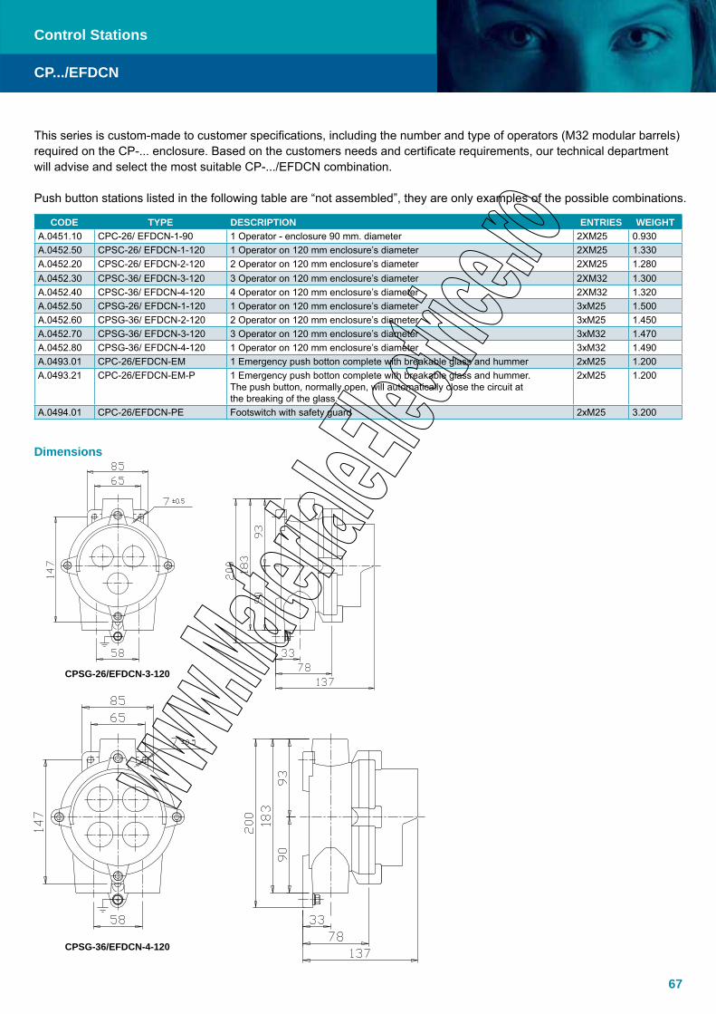
67
CP.../EFDCN
Control Stations
This series is custom-made to customer specifications, including the number and type of operators (M32 modular barrels) required on the CP-... enclosure. Based on the customers needs and certificate requirements, our technical department will advise and select the most suitable CP-.../EFDCN combination.
Push button stations listed in the following table are “not assembled”, they are only examples of the possible combinations.
CODE TYPE DESCRIPTION ENTRIES WEIGHTA.0451.10 CPC-26/ EFDCN-1-90 1 Operator - enclosure 90 mm. diameter 2XM25 0.930A.0452.50 CPSC-26/ EFDCN-1-120 1 Operator on 120 mm enclosure’s diameter 2XM25 1.330A.0452.20 CPSC-26/ EFDCN-2-120 2 Operator on 120 mm enclosure’s diameter 2XM25 1.280A.0452.30 CPSC-36/ EFDCN-3-120 3 Operator on 120 mm enclosure’s diameter 2XM32 1.300A.0452.40 CPSC-36/ EFDCN-4-120 4 Operator on 120 mm enclosure’s diameter 2XM32 1.320A.0452.50 CPSG-26/ EFDCN-1-120 1 Operator on 120 mm enclosure’s diameter 3xM25 1.500A.0452.60 CPSG-36/ EFDCN-2-120 2 Operator on 120 mm enclosure’s diameter 3xM25 1.450A.0452.70 CPSG-36/ EFDCN-3-120 3 Operator on 120 mm enclosure’s diameter 3xM32 1.470A.0452.80 CPSG-36/ EFDCN-4-120 1 Operator on 120 mm enclosure’s diameter 3xM32 1.490A.0493.01 CPC-26/EFDCN-EM 1 Emergency push botton complete with breakable glass and hummer 2xM25 1.200A.0493.21 CPC-26/EFDCN-EM-P 1 Emergency push botton complete with breakable glass and hummer.
The push button, normally open, will automatically close the circuit at the breaking of the glass.
2xM25 1.200
A.0494.01 CPC-26/EFDCN-PE Footswitch with safety guard 2xM25 3.200
Dimensions
CPSG-26/EFDCN-3-120
CPSG-36/EFDCN-4-120

68
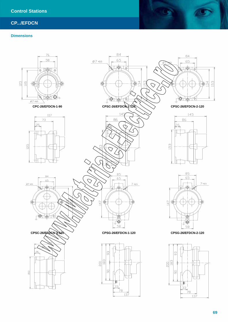
69
CP.../EFDCN
Control Stations
Dimensions
CPC-26/EFDCN-1-90 CPSC-26/EFDCN-1-120 CPSC-26/EFDCN-2-120
CPSC-26/EFDCN-3-120 CPSG-26/EFDCN-1-120 CPSG-26/EFDCN-2-120

70
The CP EFSRC range of enclosure for switches are based on the features of our CP enclosure, which offers an Ex d IIC mode of protection with or without accessories (pushbuttons, selector switches, potentiometers, signal lamps, rotary handles, ammeters, voltmeters, fuses, etc.). Enclosures are manufactured in copper free aluminium (Cu<0.1%) and completed with threaded hubs suitable for cable glands or conduit and internal threaded devices to secure DIN/Omega normalized rails for terminal strips. Connection of cable gland or conduit does not affect the internal void, which remains available for terminals and wirings. Internal and external screws are AISI304 stainless steel.
This series is customized to customer specifications, including the number and type of operators (M32 modular barrels) required on the enclosure. Based on the customer requirements, our technical department will advise and select the most suitable CP-.../EFSRC combination.
CP.../EFSRC
Control Stations
Specifications
Material Copper free aluminium (Cu<0.1%)IP Rating IP65-66Temperature -35°C to 40°C for T6 / T85°C
-35°C to 50°C for T5 / T100°C-35°C to 60°C for T4 / T135°C
Approvals- Atex- GOST
INERIS 03ATEX0009GOST Certificate
Standards EN/IEC: 60079-0, 60079-1, 60079-7, 60079-18,
EN: 61241-0, 61241-1Ex-code II 2 GD
Ex d IIC T6 / T5 / T4Ex tD A21 IP65 T85°C / T100°C / T135°Caccording to European Directive 94/9/EC (ATEX)For Zone 1 / Zone 2, Zone 21 / Zone 22
Lid / Door gasket O-ring made in Nitrile Rubber (NBR)Surface treatment Unpainted
Electrical characteristics Max. DC voltage 440 VMax. AC voltage 1000 VNominal frequency 50 / 60 HzMax. current 100 ANominal incandescent lamp power ≤ 5 WMax. LED lamp dissipated power ≤ 3 W
Internal diameter 90 mm. Entries position (C) = 2Entries thread Metric pitch 1.5, ANSI B1.20.1 NPT, UNI 6125Standard identification Identification nameplate is realized in high resistance self-adhesive polyester with thermal
transfer inscriptions
Accessories on request External polyurethane painting “Standard Cycle” Green RAL 6003
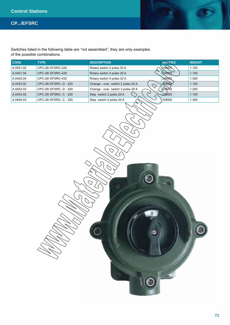
71
Switches listed in the following table are “not assembled”, they are only examples of the possible combinations.
CODE TYPE DESCRIPTION ENTRIES WEIGHT
A.0451.02 CPC-26/ EFSRC-220 Rotary switch 2 poles 20 A 2XM25 1.100
A.0451.04 CPC-26/ EFSRC-420 Rotary switch 4 poles 20 A 2XM25 1.150
A.0452.04 CPC-26/ EFSRC-432 Rotary switch 4 poles 32 A 2XM25 1.300
A.0453.02 CPC-26/ EFSRC- D - 220 Change - over switch 2 poles 20 A 2XM32 1.150
A.0453.03 CPC-26/ EFSRC- D - 320 Change - over switch 3 poles 20 A 2XM32 1.200
A.0454.02 CPC-26/ EFSRC- C - 220 Step switch 2 poles 20 A 2XM25 1.150
A.0454.03 CPC-26/ EFSRC- C - 320 Step switch 3 poles 20 A 2XM25 1.300
CP.../EFSRC
Control Stations

72
The EFQL range of Miniature Automatic Circuit Breakers are based on our EFQL Ex d enclosure manufactured in copper free aluminium and painted according to RAL 6003. The EFQL range can be delivered with automatic circuit breakers, on-load switches and selector switches up to 63A and is suitable for use indoor or outdoor, in corrosive and hazardous areas where gases, vapours and dusts may be present.
EFQL
Control Stations
ITEM NOTE WEIGHT [kg]TYPE EFQL - 3 Compatible until No. 8 steps of 9 mm. (MULTI-9) 3.250
TYPE EFQL - 4 Compatible until No. 10 steps of 9 mm. (MULTI-9) 4.600
Specifications
Material Copper free aluminium (Cu<0.1%)IP Rating IP66-67 with flanged joint coated with
silicone grease (contact our sales dept. for detailed reference)
Temperature -30°C to 55°C
Approvals- Atex- GOST
INERIS 02ATEX0027XGOST Certificate
Standards EN/IEC: 60079-0, 60079-1, 60079-7, 60079-18,
EN: 61241-0, 61241-1Ex-code II 2 GD
Ex d IIB T6Ex tD A21 IP66 T85°C
According to European Directive 94/9/EC (ATEX)For Zone 1 / Zone 2, Zone 21 / Zone 22
Surface treatment External polyurethane painting (RAL 6003)Entries No 2 Entries diam. 1” or M32
Standard Identification nameplate is realized in high resistance self-adhesive polyester with thermal transfer inscriptionsidentification
Poles 3 PolesVoltage 220/660V 50/60HzAccessories Residual Current Device ”VIGI”
Auxiliary Switch ”OF”Alarm Switch ”SD”Shunt trip release ”MX+OF”Undervoltage release ”MN”Customized colours
Note Foreseen with electrical unit up to 63 AExternal operating handle
Dimensions EFQL - 3
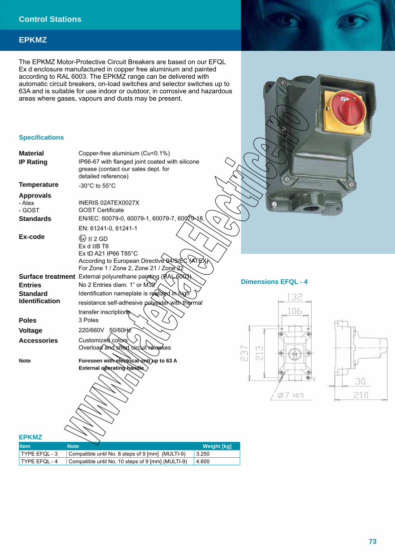
73
The EPKMZ Motor-Protective Circuit Breakers are based on our EFQL Ex d enclosure manufactured in copper free aluminium and painted according to RAL 6003. The EPKMZ range can be delivered with automatic circuit breakers, on-load switches and selector switches up to 63A and is suitable for use indoor or outdoor, in corrosive and hazardous areas where gases, vapours and dusts may be present.
Specifications
Material Copper-free aluminium (Cu<0.1%)IP Rating IP66-67 with flanged joint coated with silicone
grease (contact our sales dept. for detailed reference)
Temperature -30°C to 55°C
Approvals- Atex- GOST
INERIS 02ATEX0027XGOST Certificate
Standards EN/IEC: 60079-0, 60079-1, 60079-7, 60079-18,
EN: 61241-0, 61241-1Ex-code II 2 GD
Ex d IIB T6Ex tD A21 IP66 T85°CAccording to European Directive 94/9/EC (ATEX)For Zone 1 / Zone 2, Zone 21 / Zone 22
Surface treatment External polyurethane painting (RAL 6003)Entries No 2 Entries diam. 1” or M32Standard Identification
Identification nameplate is realized in high resistance self-adhesive polyester with thermal transfer inscriptions
Poles 3 Poles
Voltage 220/660V 50/60Hz
Accessories Customized colorsOverload and short circuit releases
Note Foreseen with electrical unit up to 63 AExternal operating handle
EPKMZItem Note Weight [kg]TYPE EFQL - 3 Compatible until No. 8 steps of 9 [mm] (MULTI-9) 3.250TYPE EFQL - 4 Compatible until No. 10 steps of 9 [mm] (MULTI-9) 4.600
EPKMZ
Control Stations
Dimensions EFQL - 4

74
The AC1WD/DE8BA range of solid and robust Ex d triple-pole starters with overload relay are ideally suited for many applications. The range is available in three variants:
• Without isolator, without fuses• Without isolator, with fuses• With isolator, with fuses
A standard range of contactors, thermal relays and disconnecting switch with or without fusible door, allows a customization of starters for various applications.
Specifications
Material Cast iron, steelIP Rating IP65-66Temperature 20°C to +40°C (+50°C, +60°C)Approvals - Atex INERIS 03ATEX0121X INERIS 03ATEX0144XStandards EN/IEC: 60079-0, 60079-1, 60079-31 EN: 61241-0, 61241-1Ex-Code II 2 GD - Ex d IIB II 2 GD - Ex d IIC
AC1WD/DE8BA
Dimensions
Control Stations

75
Triple-pole starters Ex d with overload relay without isolator, without fuse Complete with Start and Stop pushbuttons mounted on door
Rated currentMotor rating Overload
rangeGas Group and temp.
class
Basic refer-ence (2)
Complete your own reference (1)
Weight without cable
gland230V
kw400 V
kw500V
kwA A
12
. 0.37 0.75 1 to 1.6
IIB-T6 AC1WD312 •• • • • 5.000.37 0.75 1.1 1.6 to 2.5
0.75 1.5 2 2.5 to 4
1.1 2.2 3 4 to 6
1.8 3 4 5.5 to 8
IIC-T3 DE8WH2612 •• • • • 12.002.2 4 5.5 7 to 10
3 5.5 7.5 9 to 13
25
4 7.5 10 12 to 18IIB-T6 AC1WD325 •• • • • 5.50
5.5 11 15 17 to 25
IIC-T3 DE8WH2625 •• • • • 12.00
40
7.5 15 18.5 23 to 32IIB-T6 DE8BA321340 •• • • • 26.00
11 18.5 22 30 to 40
IIC-T3 DE8WH2640 •• • • • 12.00
65
15 22 30 37 to 50IIB-T6 DE8BA321365 •• • • • 26.00
15 25 37 48 to 65
IIC-T3 DE8WH2665 •• • • • 12.00
Cable glandsNumber and position Number Position
2 A, H P1 • • •
2 L, M P2 • • •
3 L, M, H P3 • • •
Thread ISO M20
1 F for non armoured cable with clamping module 1 I C
4 F for armoured câble 4 I
Without câble gland 5 I
Thread ISO M25
1 F for non armoured cable with clamping module 6 I C
4 F for armoured cable 8 I
Without câble gland 9 I
AC1WD/DE8BA
(1) When ordering, please complete your reference. Example: AC1WD321P24I(2) This basic reference, once completed, should be followed by the information: overload relay and voltage
For other configuration (range, cable gland entries)
Control Stations
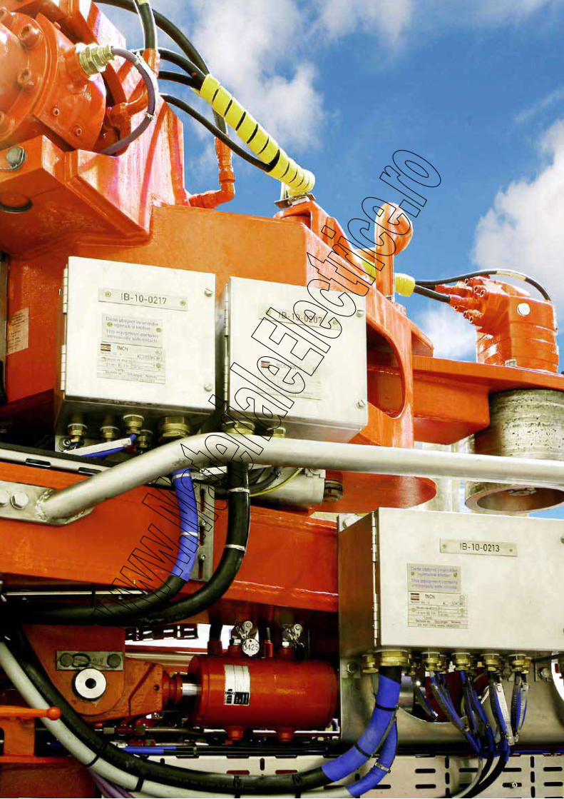
76
77
XY2WCEEmergency Trip Switch, Ex ed, Zinc Alloy
XPEWEmergency Foot Switch, Ex ed, Zinc Alloy
XMLWCNautilex Pressure Switch, Ex ed, Zinc Alloy
88
89
90
Level-, Detection- and Limit Switches
XUWBProximity Detector, Ex d, AISI 316L
XCWLimit Switch, Ex d, Zinc Alloy
XC8Limit Switch, Ex d, Cast Iron
XCKWLimit Switch, Ex ed, Zinc Alloy
78
80
82
84
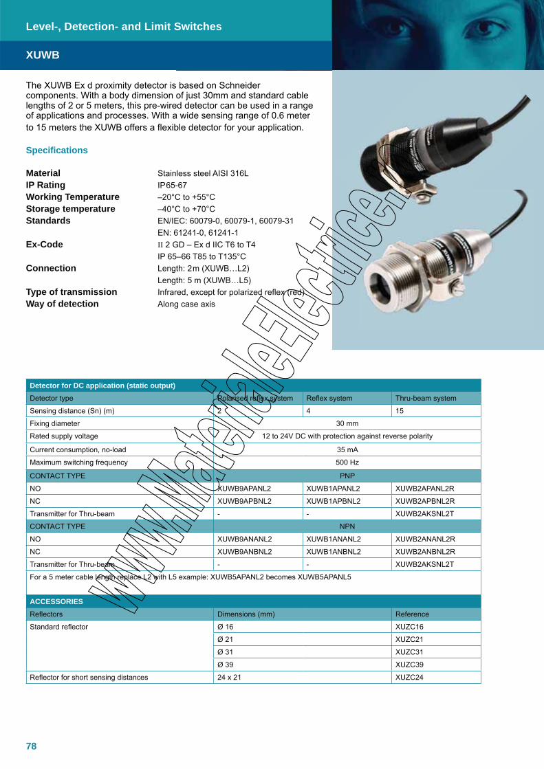
78
The XUWB Ex d proximity detector is based on Schneider components. With a body dimension of just 30mm and standard cable lengths of 2 or 5 meters, this pre-wired detector can be used in a range of applications and processes. With a wide sensing range of 0.6 meter to 15 meters the XUWB offers a flexible detector for your application.
Specifications
Material Stainless steel AISI 316LIP Rating IP65-67Working Temperature –20°C to +55°CStorage temperature –40°C to +70°C Standards EN/IEC: 60079-0, 60079-1, 60079-31 EN: 61241-0, 61241-1Ex-Code II 2 GD – Ex d IIC T6 to T4 IP 65–66 T85 to T135°CConnection Length: 2m (XUWB…L2) Length: 5 m (XUWB…L5)Type of transmission Infrared, except for polarized reflex (red)Way of detection Along case axis
XUWB
Level-, Detection- and Limit Switches
Detector for DC application (static output)Detector type Polarised reflex system Reflex system Thru-beam system
Sensing distance (Sn) (m) 2 4 15
Fixing diameter 30 mm
Rated supply voltage 12 to 24V DC with protection against reverse polarity
Current consumption, no-load 35 mA
Maximum switching frequency 500 Hz
CONTACT TYPE PNP
NO XUWB9APANL2 XUWB1APANL2 XUWB2APANL2R
NC XUWB9APBNL2 XUWB1APBNL2 XUWB2APBNL2R
Transmitter for Thru-beam - - XUWB2AKSNL2T
CONTACT TYPE NPN
NO XUWB9ANANL2 XUWB1ANANL2 XUWB2ANANL2R
NC XUWB9ANBNL2 XUWB1ANBNL2 XUWB2ANBNL2R
Transmitter for Thru-beam - - XUWB2AKSNL2T
For a 5 meter cable length replace L2 with L5 example: XUWB5APANL2 becomes XUWB5APANL5
ACCESSORIESReflectors Dimensions (mm) Reference
Standard reflector Ø 16 XUZC16
Ø 21 XUZC21
Ø 31 XUZC31
Ø 39 XUZC39
Reflector for short sensing distances 24 x 21 XUZC24

79
XUWB
Level-, Detection- and Limit Switches
Dimensions
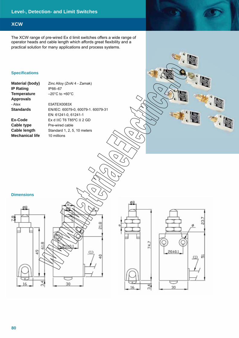
80
The XCW range of pre-wired Ex d limit switches offers a wide range of operator heads and cable length which affords great flexibility and a practical solution for many applications and process systems.
Specifications
Material (body) Zinc Alloy (ZnAl 4 - Zamak)IP Rating IP66–67Temperature –20°C to +60°CApprovals - Atex 03ATEX0083XStandards EN/IEC: 60079-0, 60079-1. 60079-31 EN: 61241-0, 61241-1Ex-Code Ex d IIC T6 T85ºC II 2 GDCable type Pre-wired cableCable length Standard 1, 2, 5, 10 metersMechanical life 10 millions
XCW
Dimensions
Level-, Detection- and Limit Switches
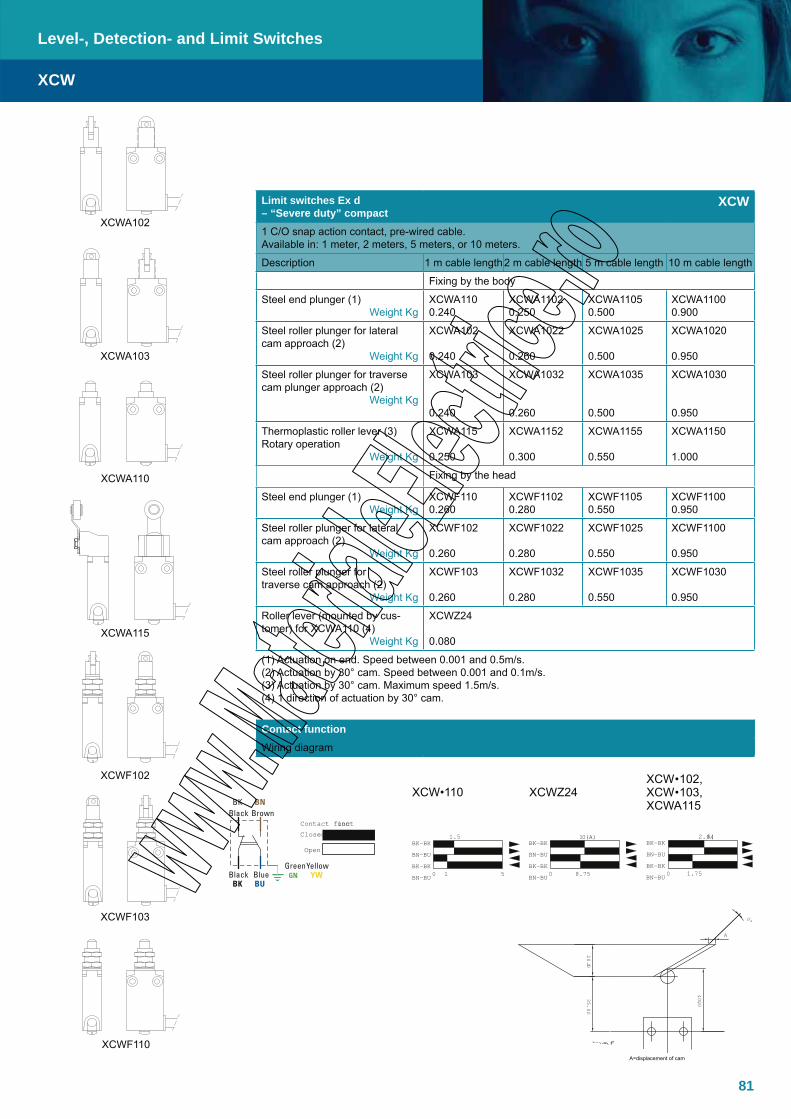
81
XCWF110
Limit switches Ex d – “Severe duty” compact
XCW
1 C/O snap action contact, pre-wired cable. Available in: 1 meter, 2 meters, 5 meters, or 10 meters.
Description 1 m cable length2 m cable length 5 m cable length 10 m cable length
Fixing by the body
Steel end plunger (1)Weight Kg
XCWA1100.240
XCWA11020.250
XCWA11050.500
XCWA11000.900
Steel roller plunger for lateral cam approach (2)
Weight Kg
XCWA102
0.240
XCWA1022
0.260
XCWA1025
0.500
XCWA1020
0.950
Steel roller plunger for traverse cam plunger approach (2)
Weight Kg
XCWA103
0.240
XCWA1032
0.260
XCWA1035
0.500
XCWA1030
0.950
Thermoplastic roller lever (3)Rotary operation
Weight Kg
XCWA115
0.250
XCWA1152
0.300
XCWA1155
0.550
XCWA1150
1.000
Fixing by the head
Steel end plunger (1)Weight Kg
XCWF1100.260
XCWF11020.280
XCWF11050.550
XCWF11000.950
Steel roller plunger for lateral cam approach (2)
Weight Kg
XCWF102
0.260
XCWF1022
0.280
XCWF1025
0.550
XCWF1100
0.950
Steel roller plunger for traverse cam approach (2)
Weight Kg
XCWF103
0.260
XCWF1032
0.280
XCWF1035
0.550
XCWF1030
0.950
Roller lever (mounted by cus-tomer) for XCWA110 (4)
Weight Kg
XCWZ24
0.080
(1) Actuation on end. Speed between 0.001 and 0.5m/s. (2) Actuation by 30° cam. Speed between 0.001 and 0.1m/s. (3) Actuation by 30° cam. Maximum speed 1.5m/s. (4) 1 direction of actuation by 30° cam.
Contact functionWiring diagram
XCW•110 XCWZ24XCW•102, XCW•103, XCWA115
BK-BKBN-BUBK-BKBN-BU 0 1.75
2.6(A)BK-BKBN-BUBK-BKBN-BU 0 1 5
1.5BK-BKBN-BUBK-BKBN-BU0 8.75
10(A)Contact functionClosed
Open
XCWA102
XCWA103
XCWA110
XCWA115
XCWF102
XCWF103
A = displacement ofcam
0°
20.0035.00
40.00
A
A=displacement of cam
YellowGreenGNBlue
BKBlack
BUYW
BrownBK
BlackBN
XCW
Level-, Detection- and Limit Switches
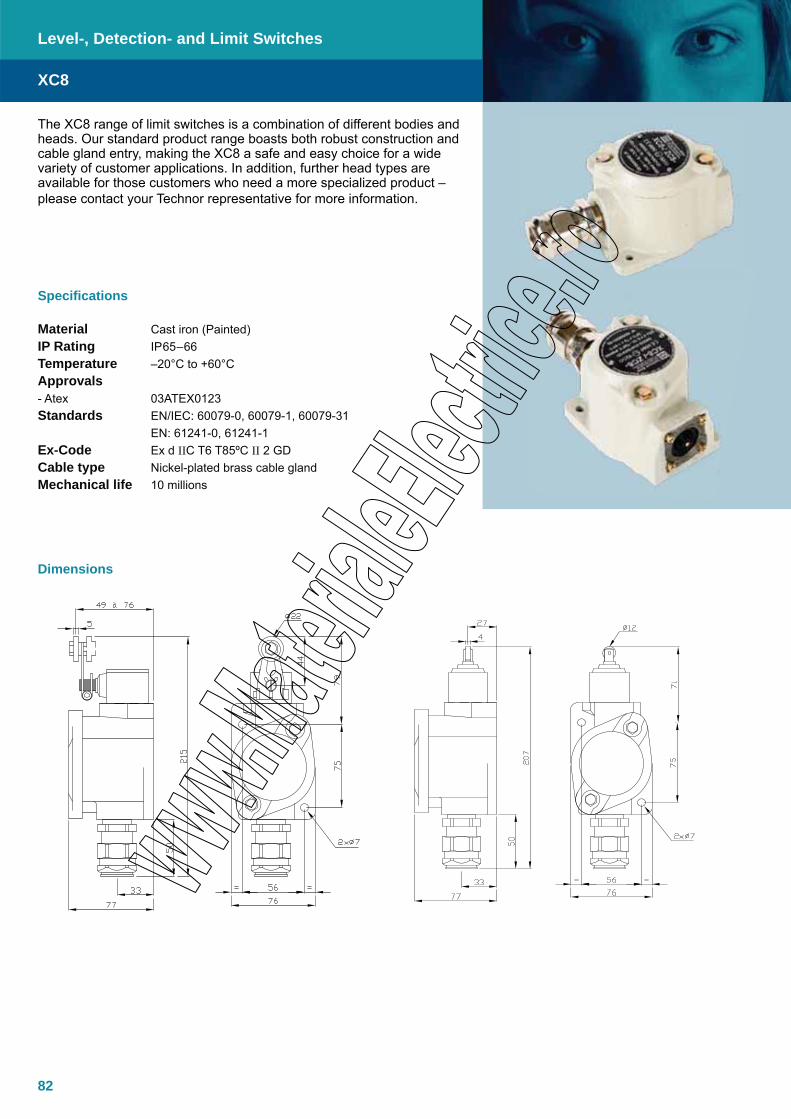
82
The XC8 range of limit switches is a combination of different bodies and heads. Our standard product range boasts both robust construction and cable gland entry, making the XC8 a safe and easy choice for a wide variety of customer applications. In addition, further head types are available for those customers who need a more specialized product – please contact your Technor representative for more information.
Specifications
Material Cast iron (Painted)IP Rating IP65–66Temperature –20°C to +60°CApprovals - Atex 03ATEX0123Standards EN/IEC: 60079-0, 60079-1, 60079-31 EN: 61241-0, 61241-1Ex-Code Ex d IIC T6 T85ºC II 2 GDCable type Nickel-plated brass cable glandMechanical life 10 millions
XC8
Level-, Detection- and Limit Switches
Dimensions

83
Limit switches Ex d – “Severe duty” XC8JC1 C/O snap action contact, with nickel cable gland ISO M20, Available for armoured cable or non armoured cable
Description
Reference Complete yourown referenceWith plunger heads
Steel plunger (1)
Weight 2 Kg
XC8JC161P1 • • •
Roller plunger (2)
Weight 2 Kg
XC8JC162P1 • • •
Side plunger (2) XC8JC163P1 • • •Weight 2 Kg
Heavy duty roller plunger (2) XC8TA1P1 • • •Weight 2.4 Kg
With rotary heads
Delrin roller lever (3) Actuation from left and right XC8JC10111P1 • • •Weight 2.2 Kg Actuation from left or right (5) XC8JC10511P1 • • •
Variable length (3) Actuation from left and right XC8JC10131P1 • • •Weight 2.2 Kg Actuation from left or right (5) XC8JC10531P1 • • •
Steel rod (4) Actuation from left and right XC8JC10151P1 • • • 3 mm, length: 125 mm Actuation from left or right (5) XC8JC10551P1 • • •
Weight 2.2 Kg
Limit switch body only 1 C/O ZC8JC1P1 • • •for plunger and rotary heads 2 C/O double pole, simultaneous ZC8JC2P1 • • •
1 C/O + 1 C/O double pole, 2 steps ZC8JC4P1 • • •Weight 2.2 Kg 1 C/O Nitrogen filled contact ZC8JCNP1 • • •
Cable gland entry
Thread ISO M20 1F for non armoured cable with clamping module 1 I C4F for armoured cable 4 IWithout cable gland 5 I
(1) Actuation on end. Maximum speed 0,5m/s. (2) Actuation by 30° cam. Maximum speed 0,5m/s. (3) Actuation by 30° cam. Maximum speed 1,5m/s. (4) Actuation by cylindrical finger. Maximum speed 1,5ms. (5) By programming the operating head.
XC8-JC161P1
XC8-JC162P1
XC8-JC163P1
XC8JC10111P1-XC8JC10511P1
Z8JC1P1-ZC8JC1P1-ZC8JC4P1
XC8JC10131P1-XC8JC10531P1
XC8JC10151P1-XC8JC10151P1
XC8TA1P1
XC8
Level-, Detection- and Limit Switches

84
The XCKW range of limit switches is based on Telemecanique series of operator heads and bodies and is equipped with Ex ed Technor contact block suitable for Zone 1 use. The products are well known around the world for their reliability, design and flexibility of application. The XCKW series are supplied with fitted cable gland for ease of installation.
Specifications
Material (body) Zink Alloy (ZnAl 4 - Zamak)IP Rating IP65Temperature -20°C to +60°CApprovals - Atex 03ATEX0038X 03ATEX0039XStandards EN/IEC: 60079-0, 60079-1, 60079-7, 60079-31 EN: 61241-0, 61241-1Ex-Code Ex ed IIC T6 T85ºC EX II 2 GDEntries ISO M20 or ISO M16Thermal current 6A with N/O + N/C (500v)
XCKWD, Compact, fixing by body (fixing centres 20mm)
Type of actuator Metal end plunger Booted metal end plunger Steel roller plunger
Thermoplastic roller lever, hori-zontal actuation
Thermoplastic roller lever, vertical actuation
Mechanical durability (millions of operating cycles) 15 10 15
Actuation speed 0.5 m/s 1 m/s
Cable entry 1 entry fitted with ISO M16 cable gland for cable Ø 5 to 8 mm
Body dimensions WxDxH (mm) 31x30x65
N/C + N/O snap action XCKWD2110P16 XCKWD2111P16 XCKWD2102P16 XCKWD2121P16 XCKWD2127P16
N/O + N/O snap action XCKWD2910P16 XCKWD2911P16 XCKWD2902P16 XCKWD2921P16 XCKWD2927P16
XCKWD, Compact, fixing by body (fixing centres 20mm)
Thermoplastic roller lever,
vertical or horiz. actuation
Thermoplastic roller lever
Thermoplastic roller leverØ 50mm
Variable lenght thermoplastic
roller lever
Variable lenght thermoplastic
roller lever Ø 50mm
”Cat’s wisker” M18 head Metal end plunger
M18 steel roller end plunger
15 10 5 10
1 m/s 1.5 m/s 1 m/s 0.5 m/s
1 entry fitted with ISO M16 cable gland for cable Ø 5 to 8 mm
31x30x65
XCK-WD2128P16
XCK-WD2118P16
XCK-WD2139P16
XCK-WD2145P16
XCK-WD2149P16
XCK-WD2106P16
XCK-WD21H0P16
XCK-WD21H2P16
XCK-WD2928P16
XCK-WD2918P16
XCK-WD2939P16
XCK-WD2945P16
XCK-WD2949P16
XCK-WD2906P16
XCK-WD29H0P16
XCK-WD29H2P16
XCKW
Level-, Detection- and Limit Switches

85
Rotary (lever)Conveyor belt shift monitoring
switch
Type of actuator
Square cross levers 6mm
crossed spring return position
Large roller rod lever thermoplas-
tic Ø 30mm
Large roller rod lever thermoplas-
tic Ø 50mm
Square cross levers 6mm
crossed stay put position
Galvanized steel operating lever
Stainless steel operating lever
Mechanical durability (mil-lions of operating cycles 10 0.3
Actuation speed 1.5m/s
Cable entry 1 entry fitted with ISO M20 for cable Ø8 to 13mm
Body dimensions WxHxD (mm) 85x75x95
2 N/O + N/C snap action, actuated in each direction XCRAW111 XCRAW121 XCRAW151 XCREW181
N/O + N/C snap action actuated in each direction XCRBW111 XCRBW121 XCRBW151 XCRFW171
2 ”N/O + 2N/C” snap action XCRTW115 XCRTW215
XCRA/B/TW, For hoisting, handling, conveyor belts (fixing centres 85x75mm)
XCKWM, Classic, fixing by body (fixing centres 41mm)
Type of actuator Metal end plunger Steel roller plungerThermoplastic
roller lever, hori-zontal actutation
Thermoplastic roller lever ”Cat’s wisker”
Mechanical durability (millions of operating cycles) 20 10
Actuation speed 0.5 m/s 1.5 m/s 0.5 m/s
Cable entry 3 entries ISO M20
Body dimensions WxDxH (mm) 63x30x64mm
N/C + N/O snap action XCKWM2110H29 XCKWM2102H29 XCKWM2121H29 XCKWM2115H29 XCKWM2106H29
XCKWJ, Compact, fixing by body (fixing centres 30x60mm)
Metal end plunger Steel roller plunger Steel roller lever Thermoplastic roller lever
Variable length thermoplastic roller
lever
Round rod lever Ø 6mm polyamide
L= 200mm
30 25 30 200.5 m/s 1 m/s 1.5 m/s
1 entry fitted ISO M20 equipped with cable gland for cable Ø 8 to 13 mm
40x44x77XCKWJ2161H29 XCKWJ2167H29 XCKWJ210513H29 XCKWJ210511H29 XCKWJ210541H29 XCKWJ210559H29
XCKW
Level-, Detection- and Limit Switches
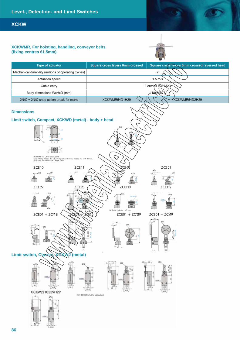
86
XCKWMR, For hoisting, handling, conveyor belts (fixing centres 61.5mm)
Type of actuator Square cross levers 6mm crossed Square cross levers 6mm crossed reversed head
Mechanical durability (millions of operating cycles) 2
Actuation speed 1.5 m/s
Cable entry 3 entries ISO M20
Body dimensions WxHxD (mm) 118x59x77
2N/C + 2N/C snap action break for make XCKWMR54D1H29 XCKWMR54D2H29
Dimensions
(1) ISO M16 x 1,5 for cable gland. (2) 2 oblongs holes ø 4,3 x 6,3 mm pitch 22 mm or 2 holes ø 4,3 pitch 20 mm. (3) 2 holes for mounting ø 3 depth 4 mm.
12ECZ 20ECZ 11ECZ 01ECZ
2HECZ 0HECZ 82ECZ 72ECZ
ZCE01 + ZCY18 ZCE01 + ZCY45 ZCE01 + ZCY39 ZCE01 + ZCY49
h l ( l)
12,5
20
12,5
30
3,5
30,5
12,5
ø 11,6 5,5
20,2
16
39ø14
2
(2)
(1)20/22
12,5
15
15
30
31
19
65
(3)
10
53
5,5
12
22
41
=2,5
12,536,2
16
713
5,5
48
29
2,5=ø22
M18x1(4)
26
12,5
ø7
38
M18x1(4)
3,5
(4) Screw thickness 3,5 mm.
37,5
5,5
12,5
16
10
42
33 78
12,5
10
16
40
12,5
40
5,524
12,5
33
52,5
142
12,5
Limit switch, Classic, XCKWJ (metal)
Limit switch, Compact, XCKWD (metal) - body + head
XCKW
Level-, Detection- and Limit Switches

87
(1) 3 ISO M20 x 1,5 for cable gland. (2) 2 centring holes ø 3,9. ø : 2 oblongs holes 6,2 x 6,5.
XCRAW111 XCRAW121 XCRAW151 XCREW181 XCRBW111 XCRBW121 XCRBW151 XCRFW171
XCR(1) ISO M20 x 1,5 for cable gland.
TW115 / XCRTW215 (2) Lever length: 200mm. (3) Lever length + roller: 160mm. (4) Lever length 300mm for XCRFW, 200mm for XCREW (5) 200 maxi – 83 mini (6) 90° maxi Ø: 2 oblongs holes 6,2 x 6,5.
35,6
5,5
15(1) 5
(2)
200
51
47
6
118
5955
77
81
11,5
61,5= =
(1)
(1)
31,5
2006,
2
6,5
26°30'
66
53
75
== 32
95
(2)
85
85== 75
(1)
18
==
6
72…60
4
9
53
75
== 32
95
(3)
85
85== 75
(1)
18
==
66
53
75
== 32
95
6
9
68
53
75
== 32
95
18
85
78
85== 75
(1) ==
102
(2)
(4)
85== 75
(1)
18
==
85
53
75
== 32
95
66
80
(5)
85
85== 75
(1)
18
==
(6) (6)
53
==
55
95 100
11
127
107 ==
Horizontal position Vertical position
==
36
==
117
95
137
11
Fixing
Limit switch, XCKWMR, XCRA/B/TW
XCKWM2110H29 XCKWM2102H29 XCKWM2121H29 XCKWM2115H29
XCK(1) 3 ISO M20 x 1,5 for cable gland.
WM2106H29(2) 2 x Ø 4. Ø: 2 oblongs holes 5,2 x 6,2.
41
64
30
==
88,5
30
14
(1)
48,5
41
64==
4
14
108
30
(1)
8
14
112,
5
30(1)
54
41
65
11,5
34,5
60,5
41
64==
5,5
22 15
119
30
34
(1)
8
14
201
30(1)
142,
5
41
64==
41
= 27 =
54
(2)
Back side
Limit switch, Classic, XCKWM (metal)
XCKW
Level-, Detection- and Limit Switches
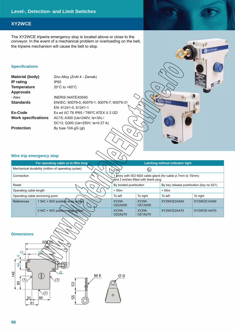
88
The XY2WCE tripwire emergency stop is located above or close to the conveyor. In the event of a mechanical problem or overloading on the belt, the tripwire mechanism will cause the belt to stop.
Specifications
Material (body) Zinc Alloy (ZnAl 4 - Zamak)IP rating IP65Temperature 20°C to +60°C Approvals - Atex INERIS 04ATEX0040Standards EN/IEC: 60079-0, 60079-1, 60079-7, 60079-31 EN: 61241-0, 61241-1Ex-Code Ex ed IIC T6 IP65 / T85ºC ATEX II 2 GDWork specifications AC15; A300 (Ue=240V, Ie=3A) / DC13; Q300 (Ue=250V, Ie=0.27 A)Protection By fuse 10A gG (gl)
XY2WCE
Level-, Detection- and Limit Switches
For operating cable ut to 50m long Latching without indicator lightMechanical durability (million of operating cycles) 0.01
Connection 1 entry with ISO M20 cable gland (for cable ø 7mm to 15mm) and 2 entries fitted with blank plug
Reset By booted pushbutton By key release pushbutton (key no 421)
Operating cable length < 50m < 50m
Operating cable anchoring point To left To right To left To right
References 1 N/C + N/O positive snap action XY2W-CE2A250
XY2W-CE1A250
XY2WCE2A450 XY2WCE1A450
2 N/C + N/O positive snap action XY2W-CE2A270
XY2W-CE1A270
XY2WCE2A470 XY2WCE1A470
Wire trip emergency stop
Dimensions
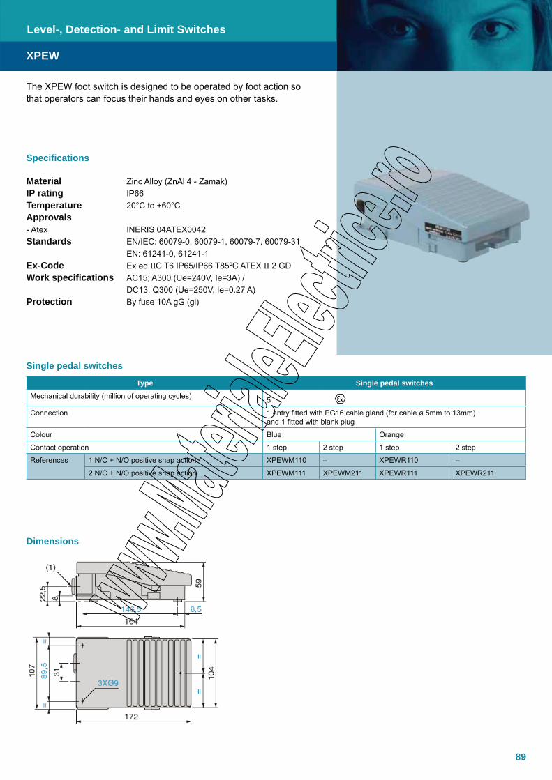
89
The XPEW foot switch is designed to be operated by foot action so that operators can focus their hands and eyes on other tasks.
Specifications
Material Zinc Alloy (ZnAl 4 - Zamak)IP rating IP66Temperature 20°C to +60°C Approvals - Atex INERIS 04ATEX0042Standards EN/IEC: 60079-0, 60079-1, 60079-7, 60079-31 EN: 61241-0, 61241-1Ex-Code Ex ed IIC T6 IP65/IP66 T85ºC ATEX II 2 GDWork specifications AC15; A300 (Ue=240V, Ie=3A) / DC13; Q300 (Ue=250V, Ie=0.27 A)Protection By fuse 10A gG (gl)
XPEW
Dimensions
Level-, Detection- and Limit Switches
Single pedal switches
Type Single pedal switchesMechanical durability (million of operating cycles) 5
Connection 1 entry fitted with PG16 cable gland (for cable ø 5mm to 13mm) and 1 fitted with blank plug
Colour Blue Orange
Contact operation 1 step 2 step 1 step 2 step
References 1 N/C + N/O positive snap action XPEWM110 – XPEWR110 –
2 N/C + N/O positive snap action XPEWM111 XPEWM211 XPEWR111 XPEWR211
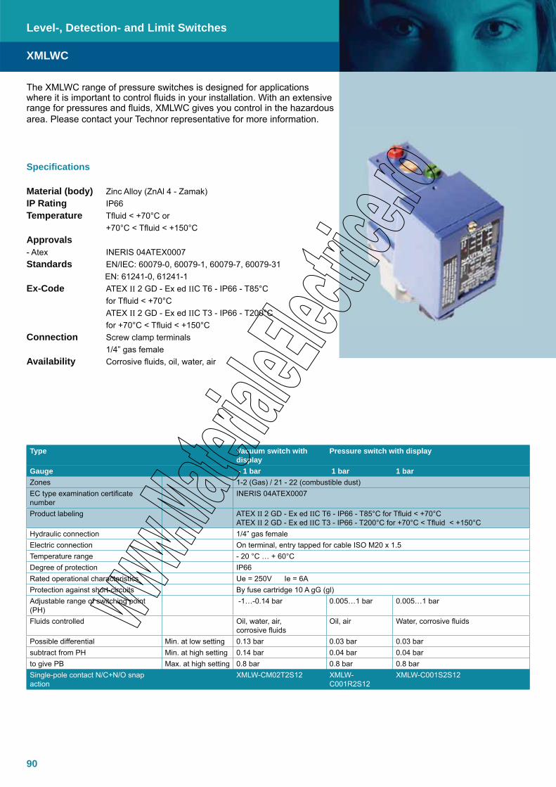
90
XMLWC
The XMLWC range of pressure switches is designed for applications where it is important to control fluids in your installation. With an extensive range for pressures and fluids, XMLWC gives you control in the hazardous area. Please contact your Technor representative for more information.
Specifications
Material (body) Zinc Alloy (ZnAl 4 - Zamak)IP Rating IP66Temperature Tfluid < +70°C or +70°C < Tfluid < +150°CApprovals - Atex INERIS 04ATEX0007Standards EN/IEC: 60079-0, 60079-1, 60079-7, 60079-31 EN: 61241-0, 61241-1Ex-Code ATEX II 2 GD - Ex ed IIC T6 - IP66 - T85°C for Tfluid < +70°C ATEX II 2 GD - Ex ed IIC T3 - IP66 - T200°C for +70°C < Tfluid < +150°CConnection Screw clamp terminals 1/4” gas female Availability Corrosive fluids, oil, water, air
Level-, Detection- and Limit Switches
Type Vacuum switch with display
Pressure switch with display
Gauge - 1 bar 1 bar 1 barZones 1-2 (Gas) / 21 - 22 (combustible dust)EC type examination certificate number
INERIS 04ATEX0007
Product labeling ATEX II 2 GD - Ex ed IIC T6 - IP66 - T85°C for Tfluid < +70°C ATEX II 2 GD - Ex ed IIC T3 - IP66 - T200°C for +70°C < Tfluid < +150°C
Hydraulic connection 1/4” gas femaleElectric connection On terminal, entry tapped for cable ISO M20 x 1.5Temperature range - 20 °C … + 60°CDegree of protection IP66Rated operational characteristics Ue = 250V Ie = 6AProtection against short-circuits By fuse cartridge 10 A gG (gl)Adjustable range of switching point (PH)
-1…-0.14 bar 0.005…1 bar 0.005…1 bar
Fluids controlled Oil, water, air, corrosive fluids
Oil, air Water, corrosive fluids
Possible differential Min. at low setting 0.13 bar 0.03 bar 0.03 barsubtract from PH Min. at high setting 0.14 bar 0.04 bar 0.04 barto give PB Max. at high setting 0.8 bar 0.8 bar 0.8 barSingle-pole contact N/C+N/O snap action
XMLW-CM02T2S12 XMLW-C001R2S12
XMLW-C001S2S12
91
Type Pressure switch with displayGauge 10 bar 20 bar 20 barZones 1-2 (Gas) / 21 - 22 (combustible dust)EC type examination certificate number INERIS 04ATEX0007Product labeling ATEX II 2 GD - Ex ed IIC T6 - IP66 - T85°C for Tfluid < +70°C
ATEX II 2 GD - Ex ed IIC T3 - IP66 - T200°C for +70°C < Tfluid < +150°CHydraulic connection 1/4” gas femaleElectric connection On terminal, entry tapped for cable ISO M20 x 1.5Temperature range - 20 °C … + 60°CDegree of protection IP66Rated operational characteristics Ue = 250V Ie = 6AProtection against short-circuits By fuse cartridge 10 A gG (gl)Adjustable range of switching point (PH) 0.7…10 bar 1.3…20 bar 1.3…20 barFluids controlled Corrosive fluids Oil, water, air Corrosive fluidsPossible differential Min. at low setting 0.45 bar 0.7 bar 0.7 barsubtract from PH Min. at high setting 0.70 bar 1 bar 1 barto give PB Max. at high setting 8 bar 11 bar 11 barSingle-pole contact N/C+N/O snap action XMLW-C010C2S12 XMLW-C020B2S12 XMLW-C020C2S12
Type Pressure switch with displayGauge 35 bar 35 barZones 1-2 (Gas) / 21 - 22 (combustible dust)EC type examination certificate number INERIS 04ATEX0007Product labeling ATEX II 2 GD - Ex ed IIC T6 - IP66 - T85°C for Tfluid < +70°C
ATEX II 2 GD - Ex ed IIC T3 - IP66 - T200°C for +70°C < Tfluid < +150°CHydraulic connection 1/4” gas femaleElectric connection On terminal, entry tapped for cable ISO M20 x 1.5Temperature range - 20 °C … + 60°CDegree of protection IP66Rated operational characteristics Ue = 250V Ie = 6AProtection against short-circuits By fuse cartridge 10 A gG (gl)Adjustable range of switching point (PH) 3.5…35 bar 3.5…35 barFluids controlled Oil, water, air Corrosive fluidsPossible differential Min. at low setting 1 bar 1 barsubtract from PH Min. at high setting 1.5 bar 1.5 barto give PB Max. at high setting 22 bar 22 barSingle-pole contact N/C+N/O snap action XMLW-C035B2S12 XMLW-C035C2S12
Type Pressure switch with displayGauge 4 bar 4 bar 10 barZones 1-2 (Gas) / 21 - 22 (combustible dust)EC type examination certificate number INERIS 04ATEX0007Product labeling ATEX II 2 GD - Ex ed IIC T6 - IP66 - T85°C for Tfluid < +70°C
ATEX II 2 GD - Ex ed IIC T3 - IP66 - T200°C for +70°C < Tfluid < +150°CHydraulic connection 1/4” gas femaleElectric connection On terminal, entry tapped for cable ISO M20 x 1.5Temperature range - 20 °C … + 60°CDegree of protection IP66Rated operational characteristics Ue = 250V Ie = 6AProtection against short-circuits By fuse cartridge 10 A gG (gl)Adjustable range of switching point (PH) 0.3…4 bar 0.3…4 bar 0.7…10 barFluids controlled Oil, water, air Corrosive fluids Oil, water, airPossible differential Min. at low setting 0.17 bar 0.17 bar 0.45 barsubtract from PH Min. at high setting 0.15 bar 0.15 bar 0.70 barto give PB Max. at high setting 2.5 bar 2.5 bar 8 barSingle-pole contact N/C+N/O snap action XMLW-C004B2S12 XMLW-C004C2S12 XMLW-C010B2S12
XMLWC
Level-, Detection- and Limit Switches
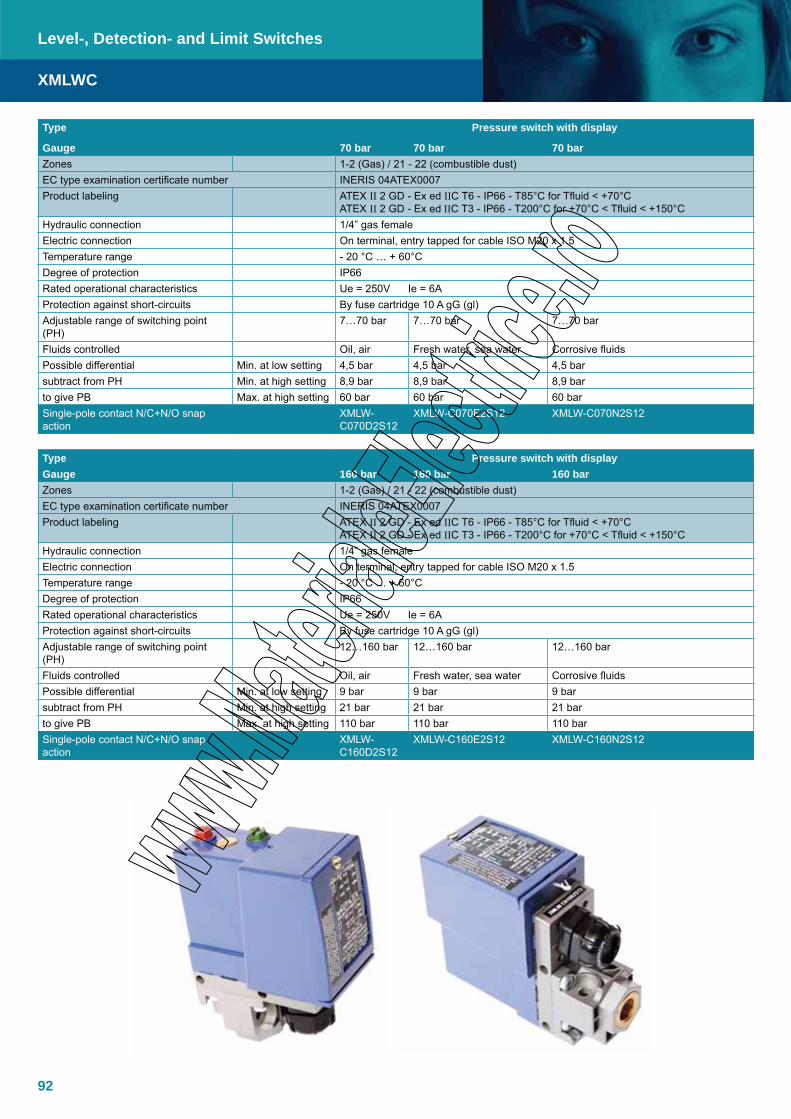
92
Type Pressure switch with display
Gauge 70 bar 70 bar 70 barZones 1-2 (Gas) / 21 - 22 (combustible dust)EC type examination certificate number INERIS 04ATEX0007Product labeling ATEX II 2 GD - Ex ed IIC T6 - IP66 - T85°C for Tfluid < +70°C
ATEX II 2 GD - Ex ed IIC T3 - IP66 - T200°C for +70°C < Tfluid < +150°CHydraulic connection 1/4” gas femaleElectric connection On terminal, entry tapped for cable ISO M20 x 1.5Temperature range - 20 °C … + 60°CDegree of protection IP66Rated operational characteristics Ue = 250V Ie = 6AProtection against short-circuits By fuse cartridge 10 A gG (gl)Adjustable range of switching point (PH)
7…70 bar 7…70 bar 7…70 bar
Fluids controlled Oil, air Fresh water, sea water Corrosive fluidsPossible differential Min. at low setting 4,5 bar 4,5 bar 4,5 barsubtract from PH Min. at high setting 8,9 bar 8,9 bar 8,9 barto give PB Max. at high setting 60 bar 60 bar 60 barSingle-pole contact N/C+N/O snap action
XMLW-C070D2S12
XMLW-C070E2S12 XMLW-C070N2S12
Type Pressure switch with displayGauge 160 bar 160 bar 160 barZones 1-2 (Gas) / 21 - 22 (combustible dust)EC type examination certificate number INERIS 04ATEX0007Product labeling ATEX II 2 GD - Ex ed IIC T6 - IP66 - T85°C for Tfluid < +70°C
ATEX II 2 GD - Ex ed IIC T3 - IP66 - T200°C for +70°C < Tfluid < +150°CHydraulic connection 1/4” gas femaleElectric connection On terminal, entry tapped for cable ISO M20 x 1.5Temperature range - 20 °C … + 60°CDegree of protection IP66Rated operational characteristics Ue = 250V Ie = 6AProtection against short-circuits By fuse cartridge 10 A gG (gl)Adjustable range of switching point (PH)
12…160 bar 12…160 bar 12…160 bar
Fluids controlled Oil, air Fresh water, sea water Corrosive fluidsPossible differential Min. at low setting 9 bar 9 bar 9 barsubtract from PH Min. at high setting 21 bar 21 bar 21 barto give PB Max. at high setting 110 bar 110 bar 110 barSingle-pole contact N/C+N/O snap action
XMLW-C160D2S12
XMLW-C160E2S12 XMLW-C160N2S12
XMLWC
Level-, Detection- and Limit Switches

93
Type Pressure switch with displayGauge 300 bar 300 bar 300 barZones 1-2 (Gas) / 21 - 22 (combustible dust)EC type examination certificate number INERIS 04ATEX0007Product labeling ATEX II 2 GD - Ex ed IIC T6 - IP66 - T85°C for Tfluid < +70°C
ATEX II 2 GD - Ex ed IIC T3 - IP66 - T200°C for +70°C < Tfluid < +150°CHydraulic connection 1/4” gas femaleElectric connection On terminal, entry tapped for cable ISO M20 x 1.5Temperature range - 20 °C … + 60°CDegree of protection IP66Rated operational characteristics Ue = 250V Ie = 6AProtection against short-circuits By fuse cartridge 10 A gG (gl)Adjustable range of switching point (PH) 22…300 bar 22…300 bar 22…300 barFluids controlled Oil, air Fresh water, sea water Corrosive fluidsPossible differential Min. at low setting 16 bar 16 bar 16 barsubtract from PH Min. at high setting 35 bar 35 bar 35 barto give PB Max. at high setting 240 bar 240 bar 240 barSingle-pole contact N/C+N/O snap action XMLW-
C300D2S12XMLW-C300E2S12 XMLW-C300N2S12
Type Pressure switch with displayGauge 500 bar 500 bar 500 barZones 1-2 (Gas) / 21 - 22 (combustible dust)EC type examination certificate number INERIS 04ATEX0007Product labeling ATEX II 2 GD - Ex ed IIC T6 - IP66 - T85°C for Tfluid < +70°C
ATEX II 2 GD - Ex ed IIC T3 - IP66 - T200°C for +70°C < Tfluid < +150°CHydraulic connection 1/4” gas femaleElectric connection On terminal, entry tapped for cable ISO M20 x 1.5Temperature range - 20 °C … + 60°CDegree of protection IP66Rated operational characteristics Ue = 250V Ie = 6AProtection against short-circuits By fuse cartridge 10 A gG (gl)Adjustable range of switching point (PH)
30…500 bar 30…500 bar 30…500 bar
Fluids controlled Oil, air Fresh water, sea water Corrosive fluidsPossible differential Min. at low setting 19 bar 19 bar 19 barsubtract from PH Min. at high setting 52 bar 52 bar 52 barto give PB Max. at high setting 340 bar 340 bar 340 barSingle-pole contact N/C+N/O snap action
XMLW-C500D2S12
XMLW-C500E2S12 XMLW-C500N2S12
20-22= =
113
37
17,5
2xØ5,2
(2)
Ø5,2 x 6,7
90 46
23
37 5
56
PH : HIGH SETUP POINT
PB : LOW POINT
Choose the pressure by adjusting the red screw '1' and adjust the low pressure by setting up the differential pressure with thegreen screw '2'.
Dimensions
XMLWC
Level-, Detection- and Limit Switches

94
95
Flameproof Enclosures
TNXCDCylindrical Enclosure, Ex d, AISI 316L
DE8BCEnclosure, Ex d/de, Semi-hardened Steel or AISI 316L
DE8WHEnclosure, Ex d/de, Semi-hardened Steel
DE1WHEnclosure, Ex e/ed, Semi-hardened Steel
EJB SeriesEnclosures for control, check and connection, Ex d IIB + H2, Copper free Aluminium
GUB SeriesEnclosures for connection, Ex d IIC, Copper free Aluminium
GUB-QL SeriesEnclosures for check and control, Ex d IIC, Copper free Aluminium
CP SeriesJunction Boxes, Ex d IIC, Copper free Aluminium
TNCDEnclosure, Ex d, AISI 316L
TNBCDEnclosure, Ex d, AISI 316L
TNDLD (Fibre optic)Line Bushing, Ex d, Acid Resistant Steel
TNDLDE (Coax cable)Line Bushing, Ex d, Acid Resistant Steel
TNDLDLine Bushing, Ex d, Acid Resistant Steel
96
97
98
99
100
102
104
108
109
112
117
118119
96
Measurement table for Ex d IIC Explosion proof enclosuresTNCD Internal dimensions
A B C D Ø a b c
TNCDWidth(mm)
Height(mm)
Depth(mm)
Total depth
Weight kg
Window(mm)
Width(mm)
Height(mm)
Depth(mm)
191918 190 190 180 213 16 65 170 170 131192818 190 190 180 213 22 65 170 260 131282827 280 280 270 300 37 65/100 260 260 217283827 280 380 270 300 49 65/100 260 360 217383827 380 380 270 300 60 65/100 360 360 217383838 380 380 380 410 72 65/100 360 360 327385727 380 570 270 300 88 65/100 360 550 215575727 570 570 270 300 125 65/100/154 550 550 213
575738 570 570 380 410 144 65/100/154 550 550 325
The TNCD range of enclosures are manufactured in 316 stainless steel and are designed to meet the requirements for Ex d IIC equipment in harsh environments on and offshore. Can be configured as Ex d direct entry or as an Ex de combination for indirect entry.
Specifications
Material Acid Resistant Stainless Steel AISI 316LIP Rating IP66 (IP67 upon request)Temperature -20ºC to +40ºC (T6), Option -40ºC to +60ºCApprovals - Atex NEMKO 03ATEX263U DNV-2003-OSL-ATEX-0135Standards EN/IEC: 60079-0, 60079-1Ex-Code Ex d IIC/IIB T6 – T4 Ex de IIC/IIB T6 - T4 II 2 G/D or II 2(1/2)G/DLid gasket VitonSurface treatment Glass blastedEarthing between Ex d and Ex e/i Through the flange assemblyenclosuresCover With or without hinges, depending on size
TNCD
Flameproof Enclosures
Viewing window TNCDViewing windows are available in the following diameters: 65mm, 100mm and154mm. The window is placed in the centre of the lid. Windows (Ø65) can also be placed on the sides or back wall.
Range of Ex e connection boxes (optional)
TNCC
E Width(mm)
F Heigth (mm)
G Depth (mm)
KgWeight
191918 190 190 180 3.0281927 280 190 270 5.2282827 280 280 270 6.6381927 380 190 270 4.6383827 380 380 270 10.5571927 570 190 270 9.6573827 570 380 270 13.4575727 570 570 270 19.7
Dimensions
97
TNXCD
Flameproof Enclosures
The TNXCD range of Ex d / de IIC enclosures are manufactured in 316 stainless steel and are designed as slim, compact, multipurpose enclo-sures. Typical applications include CCTV camera housing.
Specifications
Material Acid resistant stainless steel AISI 316LIP Rating IP66 (IP67 and IP68 upon request)Temperature Various, max: -50ºC to +60ºCApprovals - Atex, Empty enclosure DNV-2003-OSL-ATEX-0436-U- Atex, Complete enclosure DNV-2004-OSL-ATEX-0115Standards EN/IEC: 60079-0, 60079-1, 60079-7Ex-Code empty enclosure Ex d IIC/Ex de IIC, II 2 GEarthing between Ex d and Ex e enclosure Through the flange assemblyEntries Ex e glands and Ex d bushings, or Ex d glands onlyGland Size Ex e M25Gland Size Ex d According to specificationBushing Ex d Max M42, number and core size acc. to spec.
Dimensions
TNXCD Ex dA B C D Ø
TNXCD Total length (mm) Tube length (mm) Diameter (mm) Internal dia. (mm) Weight (kg) Window/Dome (mm) Internal length
XCD1003200 217.2 193 101 95 3.3 68 148
XCD1003360 384.2 360 101 95 4.1 68 315
XCD1303100 119.5 100 132 126 4.0 95 55
XCD1303200 219.5 200 132 126 5.3 95 155
XCD1303360 379.5 360 132 126 7.0 95 315
XCD1953290 305.5 290 195 187 13.0 155 238
TNXCD Ex deA B C D Ø
TNXCD Total length (mm) Tube length (mm) Diameter (mm) Internal dia. (mm) Weight (kg) Window/Dome (mm) Internal lengthXCD1002200 247.7 193 100 95 3.9 68 148
XCD1002360 414.7 360 100 95 4.8 68 315
XCD1301100 161 100 130 126 5.6 95 55
XCD1301200 261 200 130 126 6.9 95 155
XCD1301360 421 360 130 126 8.6 95 315
XCD1951290 389 290 195 187 17.1 155 238
Available with window, Dome or SS316 top
98
The DE8WH range of Ex d IIC enclosures range comprises many standard sizes of enclosures manufactured in painted carbon steel. Can be configured as Ex d direct entry or as an Ex de combination for indirect entry. If required, several enclosures can be assembled on a frame with separate or common Ex e/i junction boxes. The enclosures can be delivered empty with U component certificate or supplied fully assembled according to client demands.
Specifications
Material Semi-hardened steelIP Rating IP65-66Temperature –20°C to +40°C (+50°C, +60°C) Approvals - Atex INERIS 03ATEX0121XStandards EN/IEC: 60079-0, 60079-1, 60079-7, 60079-11, 60079-31 EN: 61241-0, 61241-1Ex-Code Ex d IIC or de IIB T6 to T4 IP6X - T85°C to T135°C ATEX II 2 GD or 2 (1) GD Ex d [ia] or d [ia] ia or de [ia] or de [ia] ia IIB T6 IP6X T85°CSurface treatment RAL 7032 Painting - Special painting on request. Drain plug Upon request
Flameproof Enclosures
Reference DE8WH
Width A
Height B
DoorØ
Depth H
Useful Depth
P
Fixing points
A1 x B1
Diameter of fixing
holes
Base plate useful surface
I x J
Max. dissipation
W
Weights Empty
kgDE8WH107 670 1040 550 360 317 720x800 Ø 14 646x1016 600 260
DE8WH64 670 670 550 300 257 720x552 Ø 14 646x646 330 200
DE8WH43 520 520 400 300 257 570x400 Ø 14 496x496 270 125
DE8WH32 330 330 250 300 257 380x210 Ø 14 306x306 165 65
DE8WH261 260 260 245 135 85 116x305 Ø 9 Ø 190 90 9
DE8WH26 260 260 230 135 175 116x305 Ø 9 Ø 190 90 12
Dimensions
Measurement table for Ex d IIC Explosion proof enclosure
DE8WH

99
The DE1WH range of Ex e enclosures are designed specifically for combination with our DE8WH range of Ex d IIC enclosures. The DE1WH can accommodate terminals for connection and lid mounted control components for control and signalling.
Specifications
Material Semi-hardened steelIP Rating IP65-66Temperature –20°C to +40°C (+50°C, +60°C)Approvals - Atex INERIS 03ATEX0006Standards EN/IEC: 60079-0, 60079-1, 60079-7, 60079-18, 60079-31 EN: 61241-0, 61241-1Ex-Code Ex e II or ed IIC or em II or emd IIC T6 to T4 IP6X - T85°C to T135°C ATEX II 2 GDSurface treatment RAL 7032 Painting – Special painting on request. Drain plug Upon request
Reference DE1WH
Width A
Height B
DepthC
Nb of command and
signal unitNb of
Ammeter
Diameter of fixing
holes
Weights empty
kgDE1WH270 270 250 230 9 2 25 6
DE1WH330 330 250 230 18 4 42 8
DE1WH520 520 330 230 40 4 72 13
DE1WH670 670 520 230 108 5 120 22
Measurement table for Ex e IIC Increase safety enclosures: DE1WH
Flameproof Enclosures
Dimensions
DE1WH
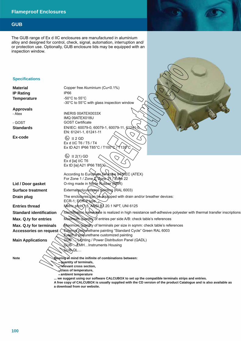
100
The GUB range of Ex d IIC enclosures are manufactured in aluminium alloy and designed for control, check, signal, automation, interruption and/or protection use. Optionally, GUB enclosure lids may be equipped with an inspection window.
GUB
Flameproof Enclosures
Specifications
Material Copper free Aluminium (Cu<0.1%)IP Rating IP66Temperature -50°C to 55°C
-30°C to 55°C with glass inspection window
Approvals- Atex
- GOST
INERIS 00ATEX0033XIMQ 09ATEX018UGOST Certificate
Standards EN/IEC: 60079-0, 60079-1, 60079-11, 61241-0, EN: 61241-1, 61241-11
Ex-code II 2 GDEx d IIC T6 / T5 / T4Ex tD A21 IP66 T85°C / T100°C / T135°C
II 2(1) GDEx d [ia] IIC T6Ex tD [ia] A21 IP66 T85°C
According to European Directive 94/9/EC (ATEX)For Zone 1 / Zone 2, Zone 21 / Zone 22
Lid / Door gasket O-ring made in Nitrile Rubber (NBR)
Surface treatment External polyurethane painting (RAL 6003)
Drain plug The enclosures can be equipped with drain and/or breather devices:ECR-1; ECR-2 type.
Entries thread Metric pitch 1.5, ANSI B1.20.1 NPT, UNI 6125
Standard identification Identification nameplate is realized in high resistance self-adhesive polyester with thermal transfer inscriptions
Max. Q.ty for entries Maximum quantity of entries per side A/B: check table’s references
Max. Q.ty for terminals Maximum quantity of terminals per size in sqmm: check table’s referencesAccessories on request External polyurethane painting “Standard Cycle” Green RAL 6003
External polyurethane customized paintingMain Applications GUB…- Lighting / Power Distribution Panel (QADL)
GUB-…EMH…Instruments HousingGUB-QL…
Note Bearing in mind the inifinite of combinations between: • quantity of terminals, • relevant cross section, • class of temperature, • ambient temperature
... we suggest using our software CALCUBOX to set up the compatible terminals strips and entries. A free copy of CALCUBOX is usually supplied with the CD version of the product Catalogue and is also available as a download from our website.
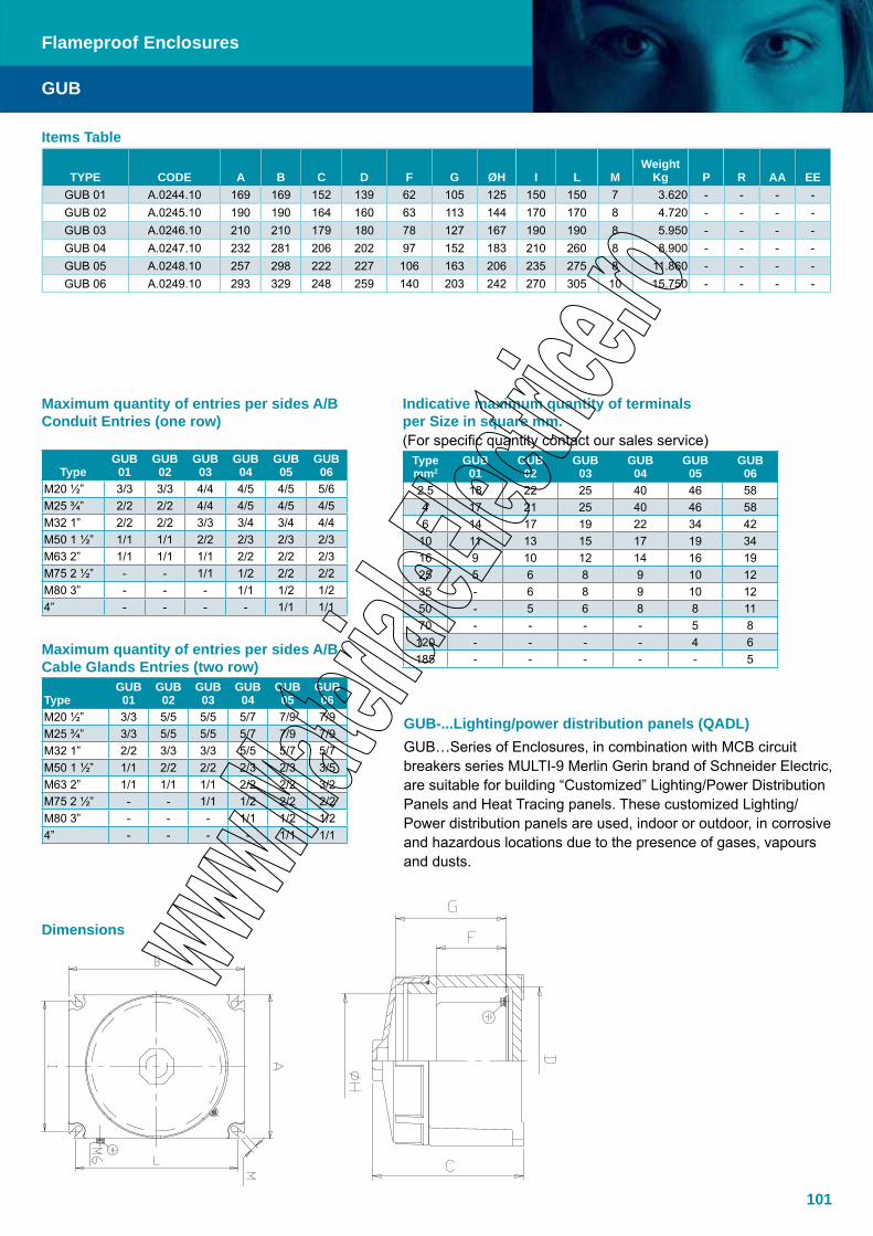
101
Items Table
TYPE CODE A B C D F G ØH I L MWeight
Kg P R AA EEGUB 01 A.0244.10 169 169 152 139 62 105 125 150 150 7 3.620 - - - -GUB 02 A.0245.10 190 190 164 160 63 113 144 170 170 8 4.720 - - - -GUB 03 A.0246.10 210 210 179 180 78 127 167 190 190 8 5.950 - - - -GUB 04 A.0247.10 232 281 206 202 97 152 183 210 260 8 8.900 - - - -GUB 05 A.0248.10 257 298 222 227 106 163 206 235 275 8 11.860 - - - -GUB 06 A.0249.10 293 329 248 259 140 203 242 270 305 10 15.750 - - - -
GUB
Flameproof Enclosures
Maximum quantity of entries per sides A/BConduit Entries (one row)
TypeGUB01
GUB02
GUB 03
GUB04
GUB 05
GUB 06
M20 ½” 3/3 3/3 4/4 4/5 4/5 5/6M25 ¾” 2/2 2/2 4/4 4/5 4/5 4/5M32 1” 2/2 2/2 3/3 3/4 3/4 4/4M50 1 ½” 1/1 1/1 2/2 2/3 2/3 2/3M63 2” 1/1 1/1 1/1 2/2 2/2 2/3M75 2 ½” - - 1/1 1/2 2/2 2/2M80 3” - - - 1/1 1/2 1/24” - - - - 1/1 1/1
Indicative maximum quantity of terminals per Size in square mm. (For specific quantity contact our sales service)
Typemm2
GUB01
GUB02
GUB03
GUB04
GUB05
GUB06
2.5 18 22 25 40 46 584 17 21 25 40 46 586 14 17 19 22 34 42
10 11 13 15 17 19 3416 9 10 12 14 16 1925 5 6 8 9 10 1235 - 6 8 9 10 1250 - 5 6 8 8 1170 - - - - 5 8
120 - - - - 4 6185 - - - - - 5
Maximum quantity of entries per sides A/BCable Glands Entries (two row)
TypeGUB01
GUB02
GUB03
GUB04
GUB05
GUB06
M20 ½” 3/3 5/5 5/5 5/7 7/9 7/9M25 ¾” 3/3 5/5 5/5 5/7 7/9 7/9M32 1” 2/2 3/3 3/3 5/5 5/7 5/7M50 1 ½” 1/1 2/2 2/2 2/3 2/3 3/5M63 2” 1/1 1/1 1/1 2/2 2/2 3/2M75 2 ½” - - 1/1 1/2 2/2 2/2M80 3” - - - 1/1 1/2 1/24” - - - - 1/1 1/1
GUB-...Lighting/power distribution panels (QADL) GUB…Series of Enclosures, in combination with MCB circuit breakers series MULTI-9 Merlin Gerin brand of Schneider Electric, are suitable for building “Customized” Lighting/Power Distribution Panels and Heat Tracing panels. These customized Lighting/Power distribution panels are used, indoor or outdoor, in corrosive and hazardous locations due to the presence of gases, vapours and dusts.
Dimensions
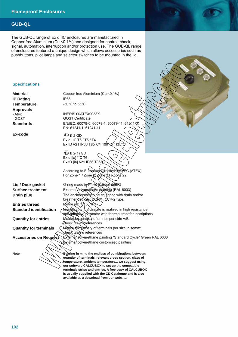
102
The GUB-QL range of Ex d IIC enclosures are manufactured in Copper free Aluminium (Cu <0.1%) and designed for control, check, signal, automation, interruption and/or protection use. The GUB-QL range of enclosures featured a unique design which allows accessories such as pushbuttons, pilot lamps and selector switches to be mounted in the lid.
GUB-QL
Flameproof Enclosures
Specifications
Material Copper free Aluminium (Cu <0.1%)IP Rating IP66Temperature -50°C to 55°CApprovals- Atex- GOST
INERIS 00ATEX0033XGOST Certificate
Standards EN/IEC: 60079-0, 60079-1, 60079-11, 61241-0, EN: 61241-1, 61241-11
Ex-code II 2 GDEx d IIC T6 / T5 / T4Ex tD A21 IP66 T85°C/T100°C/T135°C
II 2(1) GDEx d [ia] IIC T6Ex tD [ia] A21 IP66 T85°C
According to European Directive 94/9/EC (ATEX)For Zone 1 / Zone 2, Zone 21 / Zone 22
Lid / Door gasket O-ring made in Nitrile Rubber (NBR)Surface treatment External polyurethane painting (RAL 6003)Drain plug The enclosures can be equipped with drain and/or
breather devices: ECR-1; ECR-2 type.Entries thread Metric pitch 1.5, NPTStandard identification Identification nameplate is realized in high resistance
self-adhesive polyester with thermal transfer inscriptionsQuantity for entries Maximum quantity of entries per side A/B:
check table’s referencesQuantity for terminals Maximum quantity of terminals per size in sqmm:
check table’s referencesAccessories on Request External polyurethane painting “Standard Cycle” Green RAL 6003
External polyurethane customized painting
Note Bearing in mind the endless of combinations between: quantity of terminals, relevant cross section, class of temperature, ambient temperature... we suggest using our software CALCUBOX to set up the compatible terminals strips and entries. A free copy of CALCUBOX is usually supplied with the CD Catalogue and is also available as a download from our website.
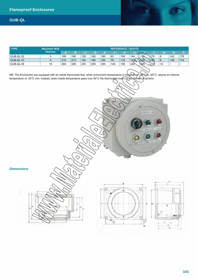
103
TYPE Maximun M32 Devices
REFERENCE / QUOTEA B C D E F G H I L M N P
GUB-QL 02 3 190 190 139 160 160 63 104 144 170 170 8 143 179 GUB-QL 03 4 210 210 160 180 180 78 119 167 190 190 8 139 174 GUB-QL 06 10 293 329 235 259 295 140 195 242 305 270 10 / /
NB. The Enclosures are equipped with an inside thermostat that, when evironment temperature is rangin from -25°C to -50°C, assure an internal temperature of -25°C min. Instead, when inside temperature goes over 40°C the thermostat must cut out the circuit tension.
Dimensions
GUB-QL
Flameproof Enclosures
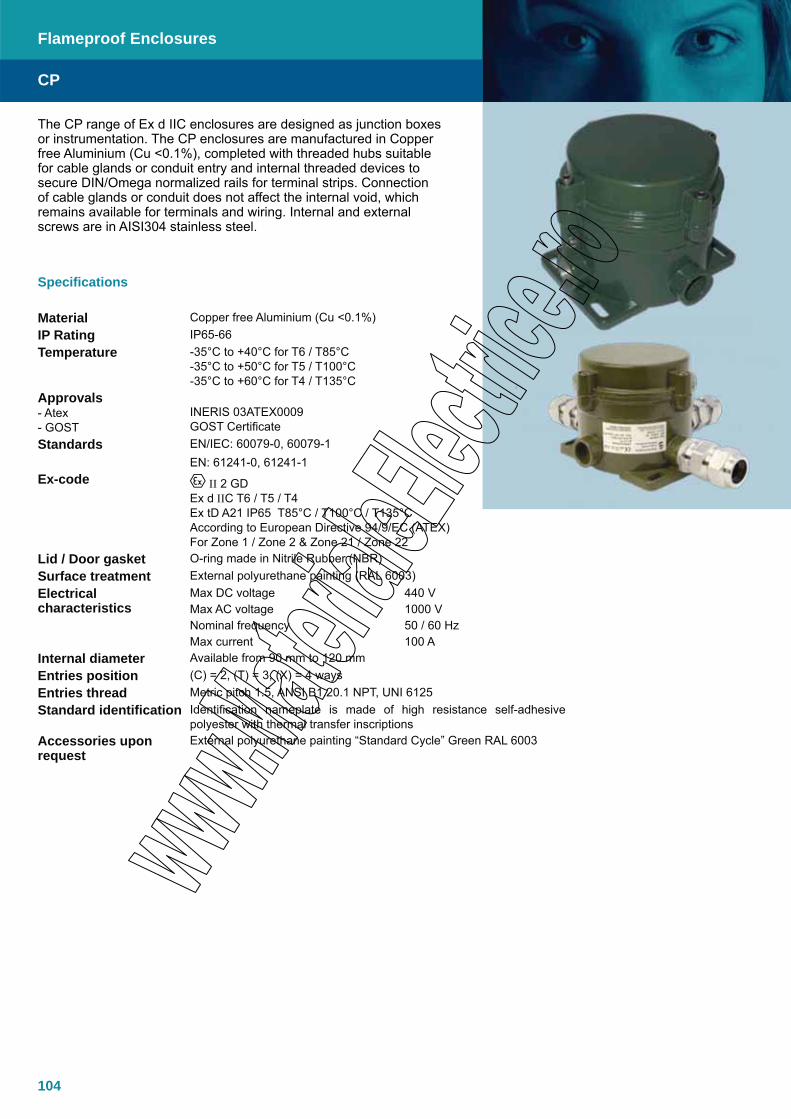
104
CP
Flameproof Enclosures
The CP range of Ex d IIC enclosures are designed as junction boxes or instrumentation. The CP enclosures are manufactured in Copper free Aluminium (Cu <0.1%), completed with threaded hubs suitable for cable glands or conduit entry and internal threaded devices to secure DIN/Omega normalized rails for terminal strips. Connection of cable glands or conduit does not affect the internal void, which remains available for terminals and wiring. Internal and external screws are in AISI304 stainless steel.
Specifications
Material Copper free Aluminium (Cu <0.1%)IP Rating IP65-66Temperature -35°C to +40°C for T6 / T85°C
-35°C to +50°C for T5 / T100°C-35°C to +60°C for T4 / T135°C
Approvals- Atex- GOST
INERIS 03ATEX0009GOST Certificate
Standards EN/IEC: 60079-0, 60079-1EN: 61241-0, 61241-1
Ex-code II 2 GDEx d IIC T6 / T5 / T4Ex tD A21 IP65 T85°C / T100°C / T135°CAccording to European Directive 94/9/EC (ATEX)For Zone 1 / Zone 2 & Zone 21 / Zone 22
Lid / Door gasket O-ring made in Nitrile Rubber (NBR)Surface treatment External polyurethane painting (RAL 6003)Electrical characteristics
Max DC voltage 440 VMax AC voltage 1000 VNominal frequency 50 / 60 HzMax current 100 A
Internal diameter Available from 90 mm to 120 mmEntries position (C) = 2, (T) = 3, (X) = 4 waysEntries thread Metric pitch 1.5, ANSI B1.20.1 NPT, UNI 6125Standard identification Identification nameplate is made of high resistance self-adhesive
polyester with thermal transfer inscriptionsAccessories upon request
External polyurethane painting “Standard Cycle” Green RAL 6003

105
CP
Flameproof Enclosures
Code Type Internal Diameter [mm] Entries Number Entries Configuration Entries Diameter Ø Weight [kg]A.0213.02 CPC- 26 90 2 C ¾” UNI-6125 0.88A.0213.22 CPC- 26 90 2 C ¾” NPT A.0213.20 CPC- 26 90 2 C M25 metric x 1.5 0.88A.0213.06 CPT- 26 90 3 T ¾” UNI-6125 0.88A.0213.26 CPT- 26 90 3 T ¾” NPT A.0213.60 CPT- 26 90 3 T M25 metric x 1.5 0.88A.0213.08 CPX- 26 90 4 X ¾” UNI-6125 0.88A.0213.28 CPX- 26 90 4 X ¾” NPT A.0213.80 CPX- 26 90 4 X M25 metric x 1.5 0.88A.0212.01 CPSC- 26 120 2 C ¾” UNI-6125 1.27A.0212.21 CPSC- 26 120 2 C ¾” NPT A.0212.20 CPSC- 26 120 2 C M25 metric x 1.5 1.27A.0212.05 CPST- 26 120 3 T ¾” UNI-6125 1.27A.0212.26 CPST- 26 120 3 T ¾” NPT A.0212.25 CPST- 26 120 3 T M25 metric x 1.5 1.27A.0212.07 CPSX- 26 120 4 X ¾” UNI-6125 1.27A.0212.27 CPSX- 26 120 4 X ¾” NPT A.0212.70 CPSX- 26 120 4 X M25 metric x 1.5 1.27A.0214.01 CPSG- 26 120 3 ¾” UNI-6125 1.27A.0214.21 CPSG- 26 120 3 ¾” NPT A.0214.10 CPSG- 26 120 3 M25 metric x 1.5 1.27A.0212.02 CPSC- 36 120 2 C 1” UNI-6125 1.27A.0212.42 CPSC- 36 120 2 C 1” NPT A.0212.32 CPSC- 36 120 2 C M32 metric x 1.5 1.27A.0212.06 CPST- 36 120 3 T 1” UNI-6125 1.27A.0212.36 CPST- 36 120 3 T 1” NPT A.0212.62 CPST- 36 120 3 T M32 metric x 1.5 1.27A.0212.08 CPSX- 36 120 4 X 1” UNI-6125 1.27A.0212.38 CPSX- 36 120 4 X 1” NPT A.0212.72 CPSX- 36 120 4 X M32 metric x 1.5 1.27A.0215.01 CPSG- 36 120 3 1” UNI-6125 1.27A.0215.31 CPSG- 36 120 3 1” NPT A.0215.32 CPSG- 36 120 3 M32 metric x 1.5 1.27
Terminal strip type
340/SP
Suitable for 3 cables 3 wires 4 sqmm : Ph # N # E Construction
Terminal type sqmmConnection per
terminal Features Colour Label Manufacturer function11546820 4 3 Spring Grey L Entrelec Phase12546822 4 3 Spring Blue N Entrelec Neutral19563712 4 3 Spring Yellow /green E Entrelec Earth
Terminal strip type
440/SP
Suitable for 4 cables 3 wires 4 sqmm : Ph # N # E Construction
Terminal type sqmmConnection per
terminal Features Colour Label Manufacturer function11547923 4 4 Spring Grey L Entrelec Phase12547925 4 4 Spring Blue N Entrelec Neutral19563823 4 4 Spring Yellow /green E Entrelec Earth
CPX-26, CPT-26, CPC-26Cross section [sqmm] Quantity/connection per terminal Features
2.5 6/2 screw/screw4 6/2 screw/screw6 6/2 screw/screw
106
Construction
Terminal type sqmmConnection per
terminal Features Colour Label Manufacturer function11546820 4 3 Spring Grey L1 Entrelec Phase11546820 4 3 Spring Grey L2 Entrelec Phase11546820 4 3 Spring Grey L3 Entrelec Phase12546822 4 3 Spring Blue N Entrelec Neutral19563712 4 3 Spring Yellow /green E Entrelec Earth
Terminal strip type440/THPN
Suitable for 4 cables 5 wires 4 sqmm : Ph # N # E
Construction
Terminal type sqmmConnection per
terminal Features Colour Label Manufacturer function11547923 4 4 Spring Grey L1 Entrelec Phase11547923 4 4 Spring Grey L2 Entrelec Phase11547923 4 4 Spring Grey L3 Entrelec Phase12547925 4 4 Spring Blue N Entrelec Neutral19563823 4 4 Spring Yellow /green E Entrelec Earth
CP
Flameproof Enclosures
Terminal strip type 340/THPN Suitable for 3 cables 5 wires 4 sqmm :
Ph # N # EConstruction
Terminal type sqmmConnection per
terminal Features Colour Label Manufacturer function11546820 4 3 Spring Grey L1 Entrelec Phase11546820 4 3 Spring Grey L2 Entrelec Phase11546820 4 3 Spring Grey L3 Entrelec Phase12546822 4 3 Spring Blue N Entrelec Neutral19563712 4 3 Spring Yellow /green E Entrelec Earth
Terminal strip type 440/THPN Suitable for 4 cables 5 wires 4 sqmm :
Ph # N # E
Construction
Terminal type sqmmConnection per
terminal Features Colour Label Manufacturer function11547923 4 4 Spring Grey L1 Entrelec Phase11547923 4 4 Spring Grey L2 Entrelec Phase11547923 4 4 Spring Grey L3 Entrelec Phase12547925 4 4 Spring Blue N Entrelec Neutral19563823 4 4 Spring Yellow /green E Entrelec Earth
CPST-36, CPSG-36 Cross section [sqmm] Quantity / connection per terminal Features
2,5 12/2 Screw/screw4 12/2 Screw/screw6 10/2 Screw/screw10 6/2 Screw/screw16 6/2 Screw/screw
Terminal strip type340/THPN
Suitable for 3 cables 5 wires 4 sqmm : Ph # N # E
CPSX-26, CPSG-26Cross section [sqmm] Quantity / connection per terminal Features
2,5 12/2 Screw/screw4 12/2 Screw/screw6 10/2 Screw/screw10 6/2 Screw/screw16 6/2 Screw/screw

107
Terminal strip type
340/THPN Suitable for 3 cables 5 wires 4 sqmm :
Ph # N # EConstruction
Terminal type sqmmConnection per
terminal Features Colour Label Manufacturer function11546820 4 3 Spring Grey L1 Entrelec Phase11546820 4 3 Spring Grey L2 Entrelec Phase11546820 4 3 Spring Grey L3 Entrelec Phase12546822 4 3 Spring Blue N Entrelec Neutral19563712 4 3 Spring Yellow /green E Entrelec EarthTerminal strip type
440/THPN Suitable for 4 cables 5 wires 4 sqmm : Ph # N # E
Construction
Terminal type sqmmConnection per
terminal Features Colour Label Manufacturer function11547923 4 4 Spring Grey L1 Entrelec Phase11547923 4 4 Spring Grey L2 Entrelec Phase11547923 4 4 Spring Grey L3 Entrelec Phase12547925 4 4 Spring Blue N Entrelec Neutral19563823 4 4 Spring Yellow /green E Entrelec Earth
CP
Flameproof Enclosures
Dimensions (mm)
CP-. CPS-..36 CPS-..26 CPS-G-26CPS-G-36
INNER VIEW CPS-..26
Cross section [sqmm] Quantity / connection per terminal Features2,5 12/2 Screw/screw4 12/2 Screw/screw6 10/2 Screw/screw

108
Range of for Ex d IIB Explosion proof enclosuresTNBCD Internal dimensions
TNBCD
A Width
(fixing) (mm)
B Height(fixing) (mm)
CDepth(mm)
WeightKg
ØWindow
(mm)
#Window
(mm)
aWide(mm)
bHeight(mm)
cDepth(mm)
262531 230 290 315 48 65/100 120x80 226 216 265
323321 360 300 215 57 65/100 120x80 286 296 165
453535 420 390 355 95 65/100/154 120x80 416 316 305
573835 545 420 355 122 65/100/154 120x80 541 346 305
TNBCD
Flameproof Enclosures
Measurement table for Ex e connection boxes (optional)TNCC
E(mm)
F(mm)
G(mm)
Weight(kg)
202025 200 200 255 3.8
252015 250 200 155 4.1
383821 380 380 255 9.2
453825 450 380 255 11.0
The TNBCD range of enclosures are manufactured in 316 stainless steel and are designed to meet the requirements for Ex d IIB equipment in harsh environments on and offshore. Can be configured as Ex d direct entry or as an Ex de combination for indirect entry.
Specifications
Material Acid Resistant Stainless Steel AISI 316LIP Rating IP66 (IP67 and IP68 upon request)Temperature –20ºC to +50ºC (T6) Option -50ºC to +60ºCApprovals - Atex NEMKO 03ATEX264U DNV-2003-OSL-ATEX-0136Standards IEC/EN: 60079-0, 60079-1Ex-Code Ex d IIC/IIB T6 – T4 II 2 G/D or II 2(1/2)G/DLid gasket VitonSurface treatment Glass blastedEarthing between Ex d and Ex e/i Through the flange assemblyenclosures Cover With or without hinges, depending on size
Dimensions
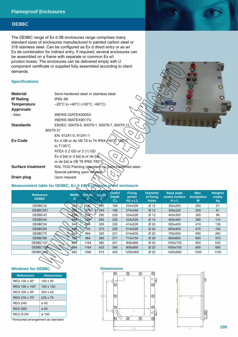
109
Dimensions
The DE8BC range of Ex d IIB enclosures range comprises many standard sizes of enclosures manufactured in painted carbon steel or 316 stainless steel. Can be configured as Ex d direct entry or as an Ex de combination for indirect entry. If required, several enclosures can be assembled on a frame with separate or common Ex e/i junction boxes. The enclosures can be delivered empty with U component certificate or supplied fully assembled according to client demands.
Specifications
Material Semi-hardened steel or stainless steelIP Rating IP65–66Temperature –20°C to +40°C (+50°C, +60°C) Approvals - Atex INERIS 03ATEX0005X INERIS 09ATEX9017UStandards EN/IEC: 60079-0, 60079-1, 60079-7, 60079-11, 60079-31 EN: 61241-0, 61241-1 Ex-Code Ex d IIB or de IIB T6 to T4 IP6X +40°C T85°C to T135°C ATEX II 2 GD or 2 (1) GD Ex d [ia] or d [ia] ia or de [ia] or de [ia] ia IIB T6 IP6X T85°CSurface treatment RAL 7032 Painting (standard for Semi-hardened steel - Special painting upon request. Drain plug Upon request
Reference DE8BC
Width A
Height B
Depth C
Useful Depth
C1
Fixing points H1 x L1
Dia meter of fixing
holes
Base plate useful surface
H x L
Max. dissipation
W
Weights empty
kgDE8BC32 334 434 240 166 234x326 Ø 12 300x200 260 51
DE8BC351 354 474 240 166 274x346 Ø 12 350x225 200 61DE8BC43 434 534 290 226 334x526 Ø 12 400x300 300 86DE8BC44 544 544 295 226 334x526 Ø 12 400x400 380 113DE8BC54 544 644 305 226 414x526 Ø 20 500x400 410 139DE8BC64 544 744 310 226 514x526 Ø 20 600x400 470 154DE8BC75 664 864 320 231 614x630 Ø 20 700x500 590 260DE8BC86 764 964 365 271 714x734 Ø 20 800x600 600 370DE8BC107 864 1164 380 251 908x868 Ø 20 1000x700 800 530DE8BC108 864 1164 425 300 908x868 Ø 20 1000x700 800 580DE8BC148 940 1590 510 425 1200x900 Ø 20 1450x800 1500 1100
Measurement table for DE8BC, Ex d IIB Explosion proof enclosure
Flameproof Enclosures
DE8BC
References DimensionsREG 100 x 50* 100 x 50
REG 100 x 100* 100 x 100
REG 200 x 45* 200 x 45
REG 235 x 75* 235 x 75
REG D45 ø 45
REG D60 ø 60
REG D150 ø 150
Windows for DE8BC
*Horizontal arrangement as standard

110
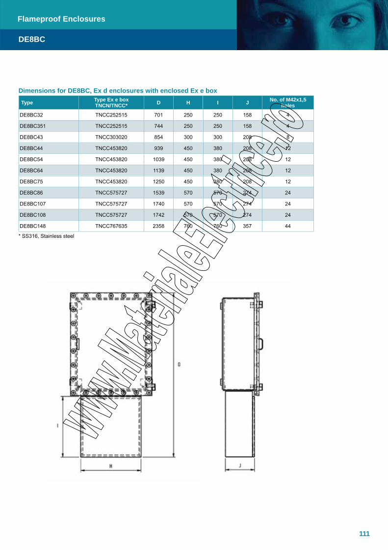
111
Dimensions for DE8BC, Ex d enclosures with enclosed Ex e box
Type Type Ex e box TNCN/TNCC* D H I J No. of M42x1,5
holes
DE8BC32 TNCC252515 701 250 250 158 4
DE8BC351 TNCC252515 744 250 250 158 4
DE8BC43 TNCC303020 854 300 300 208 8
DE8BC44 TNCC453820 939 450 380 208 12
DE8BC54 TNCC453820 1039 450 380 208 12
DE8BC64 TNCC453820 1139 450 380 208 12
DE8BC75 TNCC453820 1250 450 380 208 12
DE8BC86 TNCC575727 1539 570 570 274 24
DE8BC107 TNCC575727 1740 570 570 274 24
DE8BC108 TNCC575727 1742 570 570 274 24
DE8BC148 TNCC767635 2358 760 760 357 44
Flameproof Enclosures
DE8BC
* SS316, Stainless steel
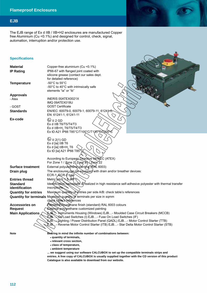
112
The EJB range of Ex d IIB / IIB+H2 enclosures are manufactured Copper free Aluminium (Cu <0.1%) and designed for control, check, signal, automation, interruption and/or protection use.
EJB
Flameproof Enclosures
Specifications
Material Copper-free aluminium (Cu <0.1%)IP Rating IP66-67 with flanged joint coated with
silicone grease (contact our sales dept. for detailed reference)
Temperature -50°C to 55°C-50°C to 40°C with intrinsically safe elements “ia” or “ib”
Approvals- Atex
- GOST
INERIS 00ATEX0021XIMQ 09ATEX018UGOST Certificate
Standards EN/IEC: 60079-0, 60079-1, 60079-11, 61241-0, EN: 61241-1, 61241-11
Ex-code II 2 GDEx d IIB T6/T5/T4/T3Ex d IIB+H2 T6/T5/T4/T3Ex tD A21 IP66 T85°C/T100°C/T135°C/T200°C
II 2(1) GDEx d [ia] IIB T6Ex d [ia] IIB+H2 T6Ex tD [ia] A21 IP66 T85°C
According to European Directive 94/9/EC (ATEX)For Zone 1 / Zone 2, Zone 21 / Zone 22
Surface treatment External polyurethane painting (RAL 6003)Drain plug The enclosures can be equipped with drain and/or breather devices:
ECR-1; ECR-2 typeEntries thread Metric pitch 1.5, NPTStandard identification
Identification nameplate is realized in high resistance self-adhesive polyester with thermal transfer inscriptions
Quantity for entries Maximum quantity of entries per side A/B: check table’s referencesQuantity for terminals Maximum quantity of terminals per size in sqmm
check table’s referencesAccessories on Request
Painted Polyurethane finish (standard) RAL 6003 coloursExternal polyurethane customized painting
Main Applications EJB…- Instruments Housing (Windows) EJB…- Moulded Case Circuit Breakers (MCCB)EJB…- On Load Switches (I) EJB…- Fuse On Load Switches (IF)EJB…- Lighting / Power Distribution Panel (QADL) EJB…- Motor Control Starter (TTB)EJB…- Reverse Motor Control Starter (ITB) EJB…- Star Delta Motor Control Starter (STB)
Note Bearing in mind the infinite number of combinations between:• quantity of terminals,• relevant cross section,• class of temperature,• ambient temperature
... we suggest using our software CALCUBOX to set up the compatible terminals strips and entries. A free copy of CALCUBOX is usually supplied together with the CD version of this product Catalogue is also available to download from our website.
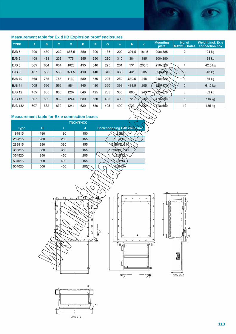
113
Measurement table for Ex d IIB Explosion proof enclosures
TYPE A B C D E F G a b c Mounting plate
No. of M42x1,5 holes
Weight incl. Ex e connection box
EJB 5 300 480 232 686,5 350 300 185 209 391,5 181.5 200x385 2 24 kg
EJB 6 408 483 238 775 355 390 280 310 384 185 300x380 4 38 kg
EJB 8 365 634 634 1026 495 340 225 261 531 205.5 250x520 4 42.5 kg
EJB 9 467 535 535 921.5 410 440 340 363 431 205 350x420 5 48 kg
EJB 10 368 755 755 1139 580 330 205 252 639.5 248 240x620 4 55 kg
EJB 11 505 596 596 984 445 480 360 393 488.5 205 380x470 5 61.5 kg
EJB 12 455 805 805 1267 640 425 285 335 690 243 325x675 8 82 kg
EJB 13 607 832 832 1244 630 580 405 499 723 236 470x690 6 116 kg
EJB 13A 607 832 832 1244 630 580 405 499 723 322 470x690 12 135 kg
Measurement table for Ex e connection boxesTNCN/TNCC
Type H I J Corresponding EJB enclosure191915 190 190 150 EJB5
282815 280 280 155 EJB6
283815 280 380 155 EJB8/EJB10
383815 380 380 155 EJB9/EJB11
354520 350 450 205 EJB12
504015 500 400 155 EJB13
504020 500 400 205 EJB13A
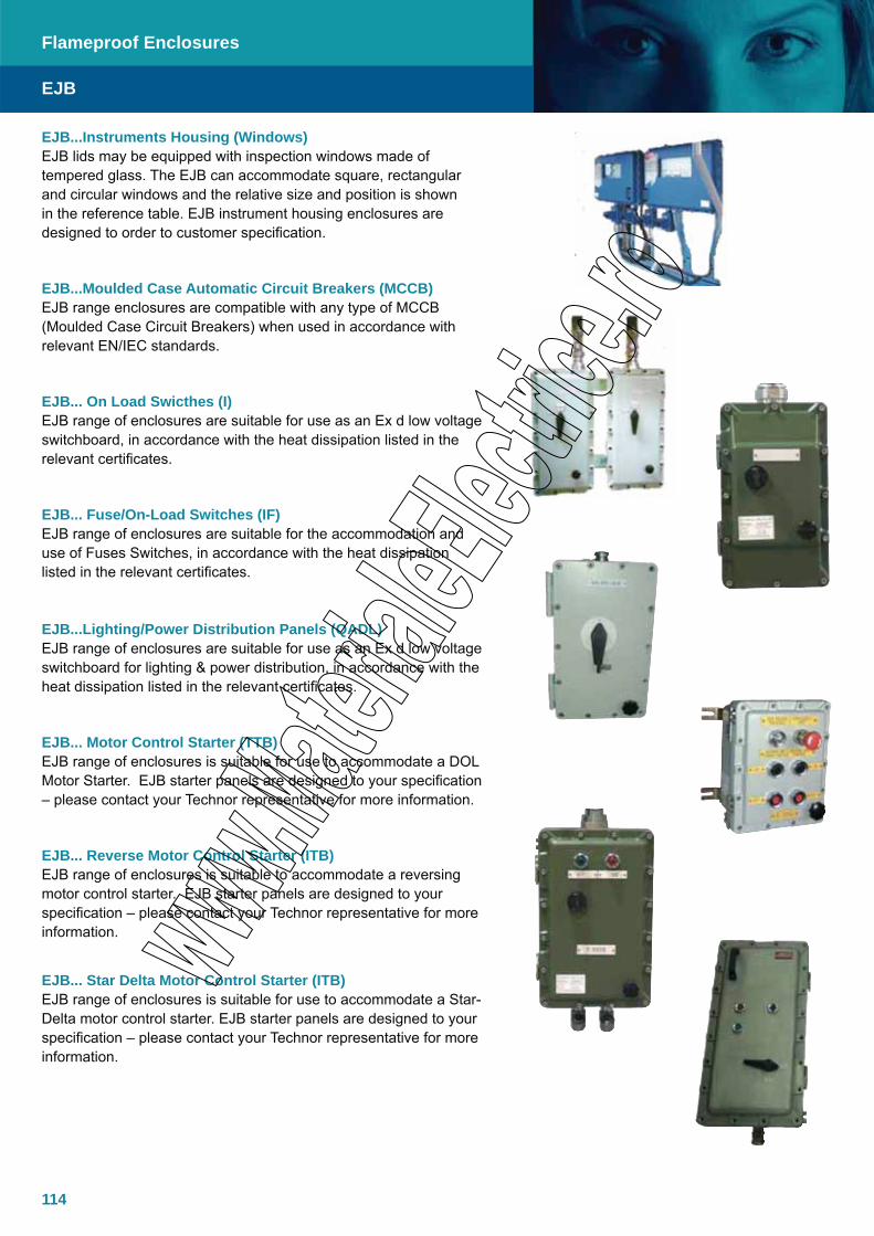
114
EJB
Flameproof Enclosures
EJB...Instruments Housing (Windows) EJB lids may be equipped with inspection windows made of tempered glass. The EJB can accommodate square, rectangular and circular windows and the relative size and position is shown in the reference table. EJB instrument housing enclosures are designed to order to customer specification.
EJB...Moulded Case Automatic Circuit Breakers (MCCB)EJB range enclosures are compatible with any type of MCCB (Moulded Case Circuit Breakers) when used in accordance with relevant EN/IEC standards.
EJB... On Load Swicthes (I) EJB range of enclosures are suitable for use as an Ex d low voltage switchboard, in accordance with the heat dissipation listed in the relevant certificates.
EJB... Fuse/On-Load Switches (IF)EJB range of enclosures are suitable for the accommodation and use of Fuses Switches, in accordance with the heat dissipation listed in the relevant certificates.
EJB...Lighting/Power Distribution Panels (QADL) EJB range of enclosures are suitable for use as an Ex d low voltage switchboard for lighting & power distribution, in accordance with the heat dissipation listed in the relevant certificates.
EJB... Motor Control Starter (TTB) EJB range of enclosures is suitable for use to accommodate a DOL Motor Starter. EJB starter panels are designed to your specification – please contact your Technor representative for more information.
EJB... Reverse Motor Control Starter (ITB) EJB range of enclosures is suitable to accommodate a reversing motor control starter. EJB starter panels are designed to your specification – please contact your Technor representative for more information.
EJB... Star Delta Motor Control Starter (ITB) EJB range of enclosures is suitable for use to accommodate a Star-Delta motor control starter. EJB starter panels are designed to your specification – please contact your Technor representative for more information.
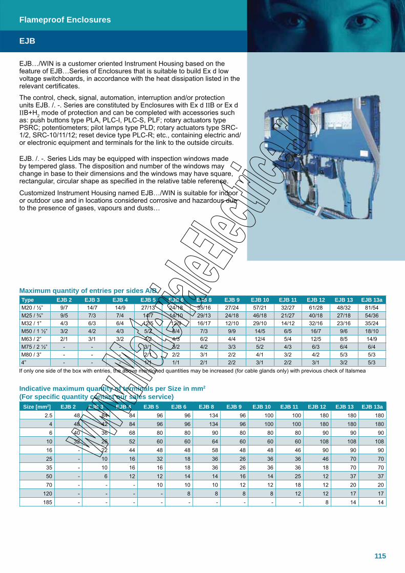
115
Maximum quantity of entries per sides A/BType EJB 2 EJB 3 EJB 4 EJB 5 EJB 6 EJB 8 EJB 9 EJB 10 EJB 11 EJB 12 EJB 13 EJB 13aM20 / ½” 9/7 14/7 14/9 27/13 24/18 35/16 27/24 57/21 32/27 61/28 48/32 81/54M25 / ¾” 9/5 7/3 7/4 14/7 14/10 29/13 24/18 46/18 21/27 40/18 27/18 54/36M32 / 1” 4/3 6/3 6/4 12/5 12/9 16/17 12/10 29/10 14/12 32/16 23/16 35/24M50 / 1 ½” 3/2 4/2 4/3 5/2 5/4 7/3 9/9 14/5 6/5 16/7 9/6 18/10M63 / 2” 2/1 3/1 3/2 4/2 4/3 6/2 4/4 12/4 5/4 12/5 8/5 14/9M75 / 2 ½” - - - 3/1 3/2 4/2 3/3 5/2 4/3 6/3 6/4 6/4M80 / 3” - - - 2/1 2/2 3/1 2/2 4/1 3/2 4/2 5/3 5/34” - - - 1/1 1/1 2/1 2/2 3/1 2/2 3/1 3/2 5/3
If only one side of the box with entries, the above mentioned quantities may be increased (for cable glands only) with previous check of Italsmea
Indicative maximum quantity of terminals per Size in mm2 (For specific quantity contact our sales service)
Size [mm2] EJB 2 EJB 3 EJB 4 EJB 5 EJB 6 EJB 8 EJB 9 EJB 10 EJB 11 EJB 12 EJB 13 EJB 13a2.5 48 84 84 96 96 134 96 100 100 180 180 180
4 48 42 84 96 96 134 96 100 100 180 180 1806 40 36 68 80 80 90 80 80 80 90 90 90
10 32 26 52 60 60 64 60 60 60 108 108 10816 - 22 44 48 48 58 48 48 46 90 90 9025 - 10 16 32 18 36 26 36 36 46 70 7035 - 10 16 16 18 36 26 36 36 18 70 7050 - 6 12 12 14 14 16 14 25 12 37 3770 - - - 10 10 10 12 12 18 12 20 20
120 - - - - 8 8 8 8 12 12 17 17185 - - - - - - - - - 8 14 14
EJB
Flameproof Enclosures
EJB…/WIN is a customer oriented Instrument Housing based on the feature of EJB…Series of Enclosures that is suitable to build Ex d low voltage switchboards, in accordance with the heat dissipation listed in the relevant certificates.
The control, check, signal, automation, interruption and/or protection units EJB. /. -. Series are constituted by Enclosures with Ex d IIB or Ex d IIB+H2 mode of protection and can be completed with accessories such as: push buttons type PLA, PLC-I, PLC-S, PLF; rotary actuators type PSRC; potentiometers; pilot lamps type PLD; rotary actuators type SRC-1/2, SRC-10/11/12; reset device type PLC-R; etc., containing electric and/or electronic equipment and terminals for the link to the outside circuits.
EJB. /. -. Series Lids may be equipped with inspection windows made by tempered glass. The disposition and number of the windows may change in base to their dimensions and the windows may have square, rectangular, circular shape as specified in the relative table reference.
Customized Instrument Housing named EJB…/WIN is suitable for indoor or outdoor use and in locations considered corrosive and hazardous due to the presence of gases, vapours and dusts…

116
EJB…/WIN…SeriesInstruments Housing
Code P.0263.26 Code P.0263.25 Code P.0263.19 Code P.0263.17B = Window on cover, applicable
glass dim. 40x70 mm.C = Window on cover, applicable
glass dim. 40x200 mm.D = Window on cover, applicable
glass dime. 100x270 mm.E = Window on cover, applicable glass
dim. 175x380 mm.
Compatible Round WindowØ mm 70 85 100 120 150 170 190 230
CODE P.0263.44 P.0263.42 P.0263.41 P.0263.39 P.0263.38 P.0263.37 P.0263.36 P.0263.35
Other window with customized dimensions are available on request when compatible with certificates
EJB
Flameproof Enclosures
Dimensions
Items
TYPE CODE A B C D E F G H I L M N ØP RWeight
[kg] AA EE
EJB 2 A.0259.10 298 238 174 230 168 95 135 205 140 250 280 9 M6 20 10.07 12 160 x 220
EJB 3 A.0260.10 412 238 177 340 167 85 136 330 150 250 280 9 M8 20 13.40 18 155 x 330
EJB 3a A.0260.13 412 238 199 340 167 85 158 330 150 250 280 9 M8 20 13.50 9 155 x 330
EJB 4 A.0261.10 418 302 175 335 220 90 132 300 190 300 320 9 M8 20 17.50 20 210 x 325
EJB 5 A.0262.10 480 300 232 392 209 125 182 350 185 300 320 9 M8 20 20.50 22 200 x 385
EJB 6 A.0263.10 483 408 238 387 310 130 186 355 280 390 420 9 M8 20 33.00 28 300 x 380
EJB 8 A.0265.10 634 365 254 530 262 140 204 495 225 340 370 9 M8 20 36.05 36 250 x 520
EJB 9 A.0266.10 535 468 257 426 363 140 204 410 340 440 470 12 M10 20 40.00 34 350 x 420
EJB 10 A.0267.10 750 366 292 630 250 185 234 580 205 330 360 12 M10 20 48.50 34 240 x 620
EJB 11 A.0268.10 596 505 267 483 394 130 204 445 360 480 510 12 M10 20 53.3 44 380 x 470
EJB 12 A.0269.10 805 455 310 690 335 170 243 640 285 425 450 14 M12 20 73.00 54 325 x 675
EJB 13 A.0270.10 832 607 314 723 500 115 236 630 405 580 620 14 M12 20 106.00 76 470 x 690
EJB 13A A.0270.13 832 607 400 723 500 205 322 630 405 580 620 14 M12 20 124.00 76 470 x 690
*ref. drawing on page 118
NB The Enclosures are equipped with an inside thermostat that, when evironment temperature is ranging from -25°C to -50°C, assure an internal temperature of -25°C min. Alternatively, when inside temperature goes over 40°C the thermostat must cut out the circuit tension.AA = Max quantity of M32x1,5 Push Botton, Pilot Lamp, Selector Swich Operators, that can be installed on the boxes cover. EE = Internal mounting plate dimension in mm.

117
Ex d Fibre bushings, -20ºC - +76ºC
TypeNumber of fibres
Fibre type
Thread size
Fibre length in mmEx e / Ex d Connector
TNDLDF 1X62.5/125 1 62.5/125 M24 750/750 ST
TNDLDF 2X62.5/125 2 62.5/125 M24 750/750 ST
TNDLDF 4X62.5/125 4 62.5/125 M24 750/750 ST
Ex d Multi fibre / line bushings, -20ºC - +76ºC
Type
Number of fibres
Fibre type
Thread size
Fibre/wire length in mm
Ex e/Ex d Connector Number
of coresWire
size mm²Rated current A with T-amb 60ºC
TNDLDF 4X62.5/ 125+10x0.75 4
62.5/ 125 M42 750/750 ST 10 0.75 9
TNDLDF 4X62.5/ 125+10x1.5 4
62.5/ 125 M42 750/750 ST 10 1.5 14
The TNDLDF range of fibre optic line bushings are designed as components for use in all Ex de enclosures to pass connection between the Ex d and Ex e compartment in combination Ex de enclosures. The TNDLDF is manufactured to order and can accommodate multiple fibre cores or a combination or fibre, wire conductor and coaxial cables.
Specifications
Material Acid resistant Stainless steel AISI 316LTemperatureTNDLD/TNDLDC/TNDLDE -20ºC to +76ºCApprovals - Atex NEMKO-01-ATEX-471U- IECEx IECEx NEM 09.0012UStandards EN/IEC: 60079-0, 60079-1Ex-Code Ex d II C II 2 G and EPL GbSurface treatment Machine treadedRated voltage Max 1000VOptions Other lengths, colours and connectors upon request
Note: Spesial conditions according to IEC/EN 60079-28 may apply for Zone 1/Gb
TNDLD (Fiber)
Flameproof Enclosures

118
The TNDLD range of line bushings are designed as components for use in all Ex de enclosures to pass connection between the Ex d and Ex e compartment in combination Ex de enclosures. The TNDLD is available in a wide range of standard configurations and can also be manufactured to order for custom or hybrid bushing requirements.
SpecificationsMaterial Acid resistant Stainless steel AISI 316LTemperatureTNDLD/TNDLDC/TNDLDE -40ºC to 110ºCApprovals - Atex NEMKO-01-ATEX-471U- IECEx IECEx NEM 09.0012UStandards EN/IEC: 60079-0, 60079-1Ex-Code Ex d II C II 2 G and EPL GbSurface treatment Machine treadedRated voltage Max 1000VColour Standard black or blue wiresType of wire Radox 125 halogen free 1250Options Other lengths and colours upon request
TNDLD
Flameproof Enclosures
TypeNumber of cores
Wire size mm²
Thread size
Wire lenght in mm
Ex e / Ex d
Rated current A with
T-amb 60ºC
TNDLD 4x0,75 4 0,75 M24 1000/1000 12
TNDLD 6x0,75 6 0,75 M24 1000/1000 11
TNDLD 12x0,75 12 0,75 M42 1000/1000 8
TNDLD 16x0,75 16 0,75 M42 1000/1000 8
TNDLD 21x0,75 21 0,75 M42 1000/1000 7
TNDLD 4X1,5 4 1,5 M24 1000/1000 19
TNDLD 6X1,5 6 1,5 M42 1000/1000 16
TNDLD 12X1,5 12 1,5 M42 1000/1000 13
TNDLD 16X1,5 16 1,5 M42 1000/1000 12
TNDLD 20X1,5 20 1,5 M42 1000/1000 11
TNDLD 4X2,5 4 2,5 M24 1000/1000 26
TNDLD 6X2,5 6 2,5 M42 1000/1000 23
TNDLD 12X2,5 12 2,5 M42 1000/1000 18
TNDLD 6x4 6 4 M42 1000/1000 31
TNDLD 6X6 6 6 M42 1000/1000 41
TNDLD 9X6 9 6 M42 1000/1000 37
TNDLD 3X10 3 10 M42 1000/1000 73
TNDLD 6X10 6 10 M42 1000/1000 59
TNDLD 3X16 3 16 M42 1000/1000 97
TNDLD 6X16 6 16 M42 1000/1000 79
TNDLD 3X25 3 25 M42 1000/1000 129
TNDLD 3X35 3 35 M42 1000/1000 163
TNDLD 3X50 3 50 M42 1000/1000 205
TNDLD 1X70 1 70 M42 1000/1000 372
TNDLD 1X95 1 95 M42 1000/1000 448
TNDLD 1X120 1 120 M42 1000/1000 523
TNDLD 1X185 1 185 M42 1000/1000 682
Ex d Line bushings blue, 1000V, -40ºC - +110ºC
TypeNumber of cores
Wiresize mm²
Thread size
Wire lenght in mm
Ex e / Ex d
Rated current A
with T-amb 60ºC
TNDLD 6x0,75B 6 0,75 M24 1000/1000 11TNDLD 16x0,75B 16 0,75 M42 1000/1000 8TNDLD 21X0,75B 21 0,75 M42 1000/1000 7TNDLD 4X1,5B 4 1,5 M24 1000/1000 19TNDLD 6X1,5B 6 1,5 M42 1000/1000 16TNDLD12X1,5B 12 1,5 M42 1000/1000 13
TNDLD 20X1,5B 20 1,5 M42 1000/1000 11
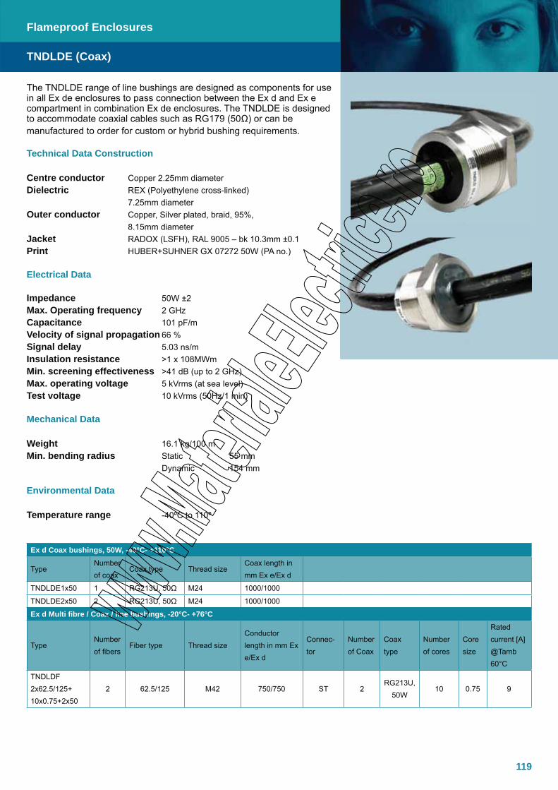
119
The TNDLDE range of line bushings are designed as components for use in all Ex de enclosures to pass connection between the Ex d and Ex e compartment in combination Ex de enclosures. The TNDLDE is designed to accommodate coaxial cables such as RG179 (50Ω) or can be manufactured to order for custom or hybrid bushing requirements.
Technical Data Construction
Centre conductor Copper 2.25mm diameterDielectric REX (Polyethylene cross-linked) 7.25mm diameterOuter conductor Copper, Silver plated, braid, 95%, 8.15mm diameterJacket RADOX (LSFH), RAL 9005 – bk 10.3mm ±0.1Print HUBER+SUHNER GX 07272 50W (PA no.)
Electrical Data
Impedance 50W ±2Max. Operating frequency 2 GHzCapacitance 101 pF/mVelocity of signal propagation 66 %Signal delay 5.03 ns/mInsulation resistance >1 x 10⁸MWmMin. screening effectiveness >41 dB (up to 2 GHz)Max. operating voltage 5 kVrms (at sea level)Test voltage 10 kVrms (50Hz/1 min)
Mechanical Data
Weight 16.1 kg/100 mMin. bending radius Static 55 mm Dynamic 154 mm
Environmental Data
Temperature range -40ºC to 110º
Ex d Coax bushings, 50W, -40°C- +110°C
TypeNumber of coax
Coax type Thread sizeCoax length in mm Ex e/Ex d
TNDLDE1x50 1 RG213U, 50Ω M24 1000/1000
TNDLDE2x50 2 RG213U, 50Ω M24 1000/1000
Ex d Multi fibre / Coax / line bushings, -20°C- +76°C
TypeNumber of fibers
Fiber type Thread sizeConductor length in mm Ex e/Ex d
Connec-tor
Number of Coax
Coax type
Number of cores
Core size
Rated current [A] @Tamb 60°C
TNDLDF 2x62.5/125+ 10x0.75+2x50
2 62.5/125 M42 750/750 ST 2RG213U,
50W10 0.75 9
TNDLDE (Coax)
Flameproof Enclosures

120

121
Pressurized Systems
TNCNPPressurized System, Ex p, AISI 316L
ELB F-351Control Unit, Ex e m, GRP, epoxy resin
122
123

122
The TNCNP range of Ex p pressurized systems are designed and pur-pose built according to each client’s requirements. The equipment allows for use of standard (non-Ex) electrical components in zone 1 and 2. Technor delivers a variety of turn-key solutions with enclosures made in Acid Resistant 316 Stainless Steel complete with purge control appara-tus, testing and certification.
Specifications
Material Acid resistant stainless steel AISI 316LIP Rating IP66-67*Temperature -40ºC to +60ºCApprovals - Atex, Complete enclosures DNV-2003-OSL-ATEX-0028- Atex, Empty enclosures DNV-2003-OSL-ATEX-0027UStandards EN/IEC: 60079-0, 60079-2Ex-Code Ex p II II 2 GLid/Door gasket Neoprene (temp. -40ºC to +100ºC) Silicone (temp. -40ºC to +200ºC)Surface treatment Acidized as standard Electro polished as option
*
TNCNP
Pressurized Systems - Cabinets
Dimensions
Without Ex p control unit: IP66-67 With Ex p control unit fitted: IP65

123
The ELB F-351 electronic purge controller is for use with Technor TNCNP Ex p pressurized systems.
Specifications
Material GRP, epoxy resin, blackIP Rating IP65Operating temperature -30ºC to +60ºC, without condensation Approvals - Atex TÜV 02ATEX1801Standards EN/IEC: 60079-0, 60079-1, 60079-2, 60079-7, 60079-11, 60079-18 EN954-1Ex-code Ex e mb ia[ia][px] IIvC T4Dimensions 122mm x 122mm x 90mm Measure range 0-25 mbarSecurity class Duo-tec technology. Fail safe, meets AK4 (according to EN954-1, cat.3)
Electrical Specifications
Current consumption 30mA at 230VAC/ 60mA at 115VAC/ 300mA at 24VAC/ 200mA at 24VDCMains Voltage 12VDC, 24VDC, 24VAC, 115VAC, 230VAC, 48…62 HzContact load C: U = 250VAC, I = 12,0A/ cos j = 1 4xEx cable glands 2xM16 for cable d = 4.5 – 10mm, 2xM20 for cable d = 7-13mmIntrinsic Safe Connector (5pole) Intrinsic safe connector for external temperature and pressure sensor F-470, remote unit F-411 or bypass-keyswitch f-480
ELB F-351
Pressurized Systems - Cabinets
Dimensions

124

125
XAWSFire Alarm Station, Ex ed, GRP 139
EV-MIOL-LED 90+90MIOL (Medium Intensity aviation Obstruction Lights), long life, Flashing, Ex nC, Glass / Copper free Aluminium, with electronic adjustable control unit
TNDSP-25 Ex bellEx bell, Ex des, Antistatic Polyamide
136
138
Audible and Visual Signals
EVde-ROT 4 SeriesRotating Signalling Lights, Ex de, Copper free Aluminium
EVde-XN / EVde-MXN / EVcc-MXN Serieslashing Signalling Lights, Ex de/d, Copper free Aluminium
WA.. SeriesLIOL (Low Intensity aviation Obstruction Lights), Steady
TNFCD, TNFAD, TNFCDMFlashing beacons, Ex d/de, Acid Resistant Steel
EVcc-5 / LED SeriesMIOL (Medium Intensity aviation Obstruction Lights), long life, Steady, Ex d, Glass / Copper free Aluminium
126
128
130
133
134
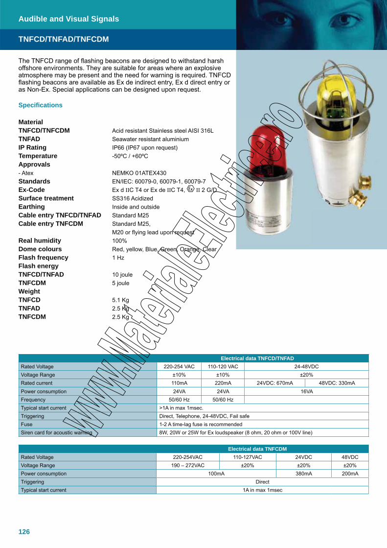
126
The TNFCD range of flashing beacons are designed to withstand harsh offshore environments. They are suitable for areas where an explosive atmosphere may be present and the need for warning is required. TNFCD flashing beacons are available as Ex de indirect entry, Ex d direct entry or as Non-Ex. Special applications can be designed upon request.
Specifications
MaterialTNFCD/TNFCDM Acid resistant Stainless steel AISI 316LTNFAD Seawater resistant aluminiumIP Rating IP66 (IP67 upon request)Temperature -50ºC / +60ºCApprovals - Atex NEMKO 01ATEX430Standards EN/IEC: 60079-0, 60079-1, 60079-7Ex-Code Ex d IIC T4 or Ex de IIC T4, II 2 G/DSurface treatment SS316 Acidized Earthing Inside and outsideCable entry TNFCD/TNFAD Standard M25Cable entry TNFCDM Standard M25, M20 or flying lead upon requestReal humidity 100%Dome colours Red, yellow, Blue, Green, Orange, ClearFlash frequency 1 HzFlash energy TNFCD/TNFAD 10 jouleTNFCDM 5 jouleWeightTNFCD 5.1 KgTNFAD 2.5 KgTNFCDM 2.5 Kg
TNFCD/TNFAD/TNFCDM
Audible and Visual Signals
Electrical data TNFCD/TNFADRated Voltage 220-254 VAC 110-120 VAC 24-48VDCVoltage Range ±10% ±10% ±20%Rated current 110mA 220mA 24VDC: 670mA 48VDC: 330mAPower consumption 24VA 24VA 16VAFrequency 50/60 Hz 50/60 HzTypical start current >1A in max 1msec.Triggering Direct, Telephone, 24-48VDC, Fail safeFuse 1-2 A time-lag fuse is recommendedSiren card for acoustic warning 8W, 20W or 25W for Ex loudspeaker (8 ohm, 20 ohm or 100V line)
Electrical data TNFCDMRated Voltage 220-254VAC 110-127VAC 24VDC 48VDCVoltage Range 190 – 272VAC ±20% ±20% ±20%Power consumption 100mA 380mA 200mATriggering DirectTypical start current 1A in max 1msec

127
TNFCD/TNFAD/TNFCDM
Audible and Visual Signals
Dimensions
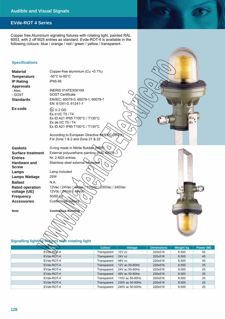
128
Copper free Aluminium signaling fixtures with rotating light, painted RAL 6003, with 2 off M25 entries as standard. Evde-ROT-4 is available in the following colours: blue / orange / red / green / yellow / transparent.
Type Colour Voltage Dimensions Weight kg Power (W)EVde-ROT-4 Transparent 12V cc 220x516 8.500 45EVde-ROT-4 Transparent 24V cc 220x516 8.500 45EVde-ROT-4 Transparent 48V cc 220x516 8.500 45EVde-ROT-4 Transparent 12V ac 50-60Hz 220x516 8.500 25EVde-ROT-4 Transparent 24V ac 50-60Hz 220x516 8.500 25EVde-ROT-4 Transparent 48V ac 50-60Hz 220x516 8.500 25EVde-ROT-4 Transparent 110V ac 50-60Hz 220x516 8.500 25EVde-ROT-4 Transparent 230V ac 50-60Hz 220x516 8.500 25EVde-ROT-4 Transparent 240V ac 50-60Hz 220x516 8.500 25
EVde-ROT 4 Series
Audible and Visual Signals
Specifications
Material Copper-free aluminium (Cu <0.1%)Temperature -50°C to 60°CIP Rating IP65-66Approvals- Atex- GOST
INERIS 01ATEX0019XGOST Certificate
Standards EN/IEC: 60079-0, 60079-1, 60079-7 EN: 61241-0, 61241-1
Ex-code II 2 GDEx d IIC T5 / T4 Ex tD A21 IP65 T100°C / T135°CEx de IIC T5 / T4Ex tD A21 IP65 T100°C / T135°C
According to European Directive 94/9/EC (ATEX)For Zone 1 & 2 and Zone 21 & 22
Gaskets O-ring made in Nitrile Rubber (NBR)Surface treatment External polyurethane painting (RAL 6003)Entries Nr. 2 M25 entriesHardware and Screw
Stainless steel external hardware
Lamps Lamp includedLamps Wattage 25W
Ballast N.A.Rated operation voltage (UE)
12Vac / 24Vac / 48Vac / 110Vac / 230Vac / 240Vac12Vdc / 24Vdc / 48Vdc
Frequency 50/60 HzAccessories Customized colours
Note Continuous Running
Signalling lighting fixtures with rotating light

129
Type Colour Voltage Dimensions Weight kg Power (W)EVde-ROT-4 Blue 12V cc 220x516 8.500 45EVde-ROT-4 Blue 24V cc 220x516 8.500 45EVde-ROT-4 Blue 48V cc 220x516 8.500 45EVde-ROT-4 Blue 12V ac 50-60Hz 220x516 8.500 25EVde-ROT-4 Blue 24V ac 50-60Hz 220x516 8.500 25EVde-ROT-4 Blue 48V ac 50-60Hz 220x516 8.500 25EVde-ROT-4 Blue 110V ac 50-60Hz 220x516 8.500 25EVde-ROT-4 Blue 230V ac 50-60Hz 220x516 8.500 25EVde-ROT-4 Blue 240V ac 50-60Hz 220x516 8.500 25
Type Colour Voltage Dimensions Weight kg Power (W)EVde-ROT-4 Orange 12V cc 220x516 8.500 45EVde-ROT-4 Orange 24V cc 220x516 8.500 45EVde-ROT-4 Orange 48V cc 220x516 8.500 45EVde-ROT-4 Orange 12V ac 50-60Hz 220x516 8.500 25EVde-ROT-4 Orange 24V ac 50-60Hz 220x516 8.500 25EVde-ROT-4 Orange 48V ac 50-60Hz 220x516 8.500 25EVde-ROT-4 Orange 110V ac 50-60Hz 220x516 8.500 25EVde-ROT-4 Orange 230V ac 50-60Hz 220x516 8.500 25EVde-ROT-4 Orange 240V ac 50-60Hz 220x516 8.500 25
Type Colour Voltage Dimensions Weight kg Power (W)EVde-ROT-4 Red 12V cc 220x516 8.500 45EVde-ROT-4 Red 24V cc 220x516 8.500 45EVde-ROT-4 Red 48V cc 220x516 8.500 45EVde-ROT-4 Red 12V ac 50-60Hz 220x516 8.500 25EVde-ROT-4 Red 24V ac 50-60Hz 220x516 8.500 25EVde-ROT-4 Red 48V ac 50-60Hz 220x516 8.500 25EVde-ROT-4 Red 110V ac 50-60Hz 220x516 8.500 25EVde-ROT-4 Red 230V ac 50-60Hz 220x516 8.500 25EVde-ROT-4 Red 240V ac 50-60Hz 220x516 8.500 25
Type Colour Voltage Dimensions Weight kg Power (W)EVde-ROT-4 Green 12V cc 220x516 8.500 45EVde-ROT-4 Green 24V cc 220x516 8.500 45EVde-ROT-4 Green 48V cc 220x516 8.500 45EVde-ROT-4 Green 12V ac 50-60Hz 220x516 8.500 25EVde-ROT-4 Green 24V ac 50-60Hz 220x516 8.500 25EVde-ROT-4 Green 48V ac 50-60Hz 220x516 8.500 25EVde-ROT-4 Green 110V ac 50-60Hz 220x516 8.500 25EVde-ROT-4 Green 230V ac 50-60Hz 220x516 8.500 25EVde-ROT-4 Green 240V ac 50-60Hz 220x516 8.500 25
Type Colour Voltage Dimensions Weight kg Power (W)EVde-ROT-4 Yellow 12V cc 220x516 8.500 45EVde-ROT-4 Yellow 24V cc 220x516 8.500 45EVde-ROT-4 Yellow 48V cc 220x516 8.500 45EVde-ROT-4 Yellow 12V ac 50-60Hz 220x516 8.500 25EVde-ROT-4 Yellow 24V ac 50-60Hz 220x516 8.500 25EVde-ROT-4 Yellow 48V ac 50-60Hz 220x516 8.500 25EVde-ROT-4 Yellow 110V ac 50-60Hz 220x516 8.500 25EVde-ROT-4 Yellow 230V ac 50-60Hz 220x516 8.500 25EVde-ROT-4 Yellow 240V ac 50-60Hz 220x516 8.500 25
EVde-ROT 4 Series
Audible and Visual Signals
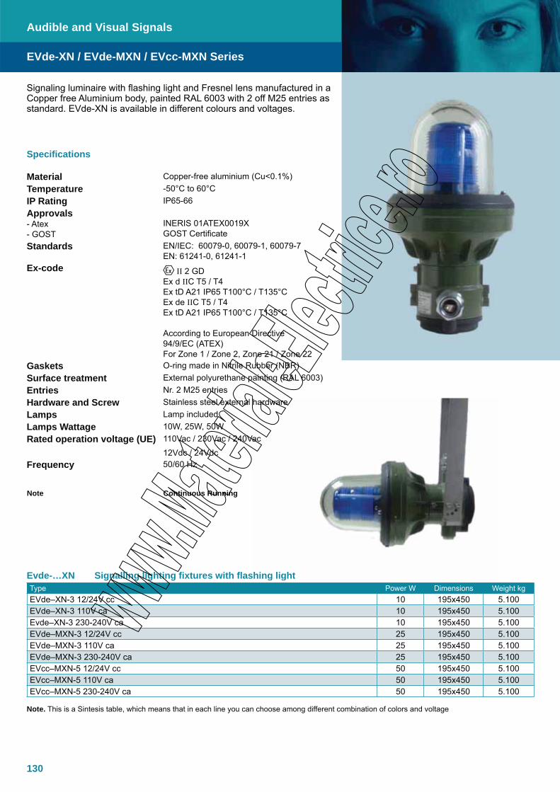
130
Evde-…XN Signalling lighting fixtures with flashing lightType Power W Dimensions Weight kgEVde–XN-3 12/24V cc 10 195x450 5.100EVde–XN-3 110V ca 10 195x450 5.100Evde–XN-3 230-240V ca 10 195x450 5.100EVde–MXN-3 12/24V cc 25 195x450 5.100EVde–MXN-3 110V ca 25 195x450 5.100EVde–MXN-3 230-240V ca 25 195x450 5.100EVcc–MXN-5 12/24V cc 50 195x450 5.100EVcc–MXN-5 110V ca 50 195x450 5.100EVcc–MXN-5 230-240V ca 50 195x450 5.100
Note. This is a Sintesis table, which means that in each line you can choose among different combination of colors and voltage
Audible and Visual Signals
Specifications
Material Copper-free aluminium (Cu<0.1%)Temperature -50°C to 60°CIP Rating IP65-66Approvals- Atex- GOST
INERIS 01ATEX0019XGOST Certificate
Standards EN/IEC: 60079-0, 60079-1, 60079-7 EN: 61241-0, 61241-1
Ex-code II 2 GDEx d IIC T5 / T4 Ex tD A21 IP65 T100°C / T135°CEx de IIC T5 / T4Ex tD A21 IP65 T100°C / T135°C
According to European Directive 94/9/EC (ATEX)For Zone 1 / Zone 2, Zone 21 / Zone 22
Gaskets O-ring made in Nitrile Rubber (NBR)Surface treatment External polyurethane painting (RAL 6003)Entries Nr. 2 M25 entriesHardware and Screw Stainless steel external hardwareLamps Lamp includedLamps Wattage 10W, 25W, 50WRated operation voltage (UE) 110Vac / 230Vac / 240Vac
12Vdc / 24VdcFrequency 50/60 Hz
Note Continuous Running
Signaling luminaire with flashing light and Fresnel lens manufactured in a Copper free Aluminium body, painted RAL 6003 with 2 off M25 entries as standard. EVde-XN is available in different colours and voltages.
EVde-XN / EVde-MXN / EVcc-MXN Series
hing light
hardware
ac

131
Listed below you can find all the possible combinations, each of them listed with a unique code…Type COLOR VOLTAGE Power (W) Dimensions Weight kgEVde–XN-3 Blue 12V cc 10 195x450 5.100EVde–XN-3 Blue 24V cc 10 195x450 5.100Evde–XN-3 Blue 110V ac 10 195x450 5.100Evde–XN-3 Blue 230-240V ac 10 195x450 5.100EVde–MXN-3 Blue 12V cc 25 195x450 5.100EVde–MXN-3 Blue 24V cc 25 195x450 5.100EVde–MXN-3 Blue 110V ac 25 195x450 5.100EVde–MXN-3 Blue 230-240V ac 25 195x450 5.100EVcc–MXN-5 Blue 12V cc 50 195x450 5.100EVcc–MXN-5 Blue 24V cc 50 195x450 5.100EVcc–MXN-5 Blue 110V ac 50 195x450 5.100EVcc–MXN-5 Blue 230-240V ac 50 195x450 5.100
Type COLOR VOLTAGE Power (W) Dimensions Weight kgEVde–XN-3 Orange 12V cc 10 195x450 5.100EVde–XN-3 Orange 24V cc 10 195x450 5.100Evde–XN-3 Orange 110V ac 10 195x450 5.100Evde–XN-3 Orange 230-240V ac 10 195x450 5.100EVde–MXN-3 Orange 12V cc 25 195x450 5.100EVde–MXN-3 Orange 24V cc 25 195x450 5.100EVde–MXN-3 Orange 110V ac 25 195x450 5.100EVde–MXN-3 Orange 230-240V ac 25 195x450 5.100EVcc–MXN-5 Orange 12V cc 50 195x450 5.100EVcc–MXN-5 Orange 24V cc 50 195x450 5.100EVcc–MXN-5 Orange 110V ac 50 195x450 5.100EVcc–MXN-5 Orange 230-240V ac 50 195x450 5.100
EVde-XN / EVde-MXN / EVcc-MXN Series
Audible and Visual Signals
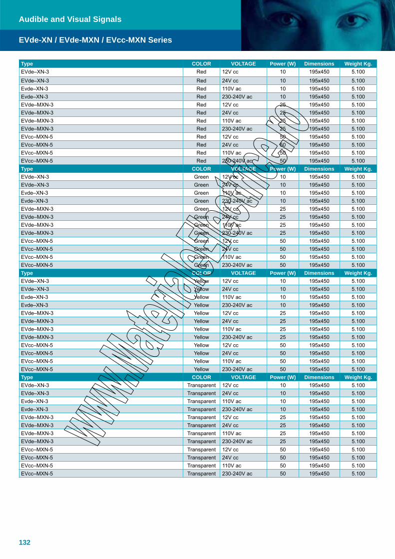
132
Type COLOR VOLTAGE Power (W) Dimensions Weight Kg.EVde–XN-3 Red 12V cc 10 195x450 5.100
EVde–XN-3 Red 24V cc 10 195x450 5.100Evde–XN-3 Red 110V ac 10 195x450 5.100Evde–XN-3 Red 230-240V ac 10 195x450 5.100EVde–MXN-3 Red 12V cc 25 195x450 5.100EVde–MXN-3 Red 24V cc 25 195x450 5.100EVde–MXN-3 Red 110V ac 25 195x450 5.100EVde–MXN-3 Red 230-240V ac 25 195x450 5.100EVcc–MXN-5 Red 12V cc 50 195x450 5.100EVcc–MXN-5 Red 24V cc 50 195x450 5.100EVcc–MXN-5 Red 110V ac 50 195x450 5.100EVcc–MXN-5 Red 230-240V ac 50 195x450 5.100Type COLOR VOLTAGE Power (W) Dimensions Weight Kg.EVde–XN-3 Green 12V cc 10 195x450 5.100EVde–XN-3 Green 24V cc 10 195x450 5.100Evde–XN-3 Green 110V ac 10 195x450 5.100Evde–XN-3 Green 230-240V ac 10 195x450 5.100EVde–MXN-3 Green 12V cc 25 195x450 5.100EVde–MXN-3 Green 24V cc 25 195x450 5.100EVde–MXN-3 Green 110V ac 25 195x450 5.100EVde–MXN-3 Green 230-240V ac 25 195x450 5.100EVcc–MXN-5 Green 12V cc 50 195x450 5.100EVcc–MXN-5 Green 24V cc 50 195x450 5.100EVcc–MXN-5 Green 110V ac 50 195x450 5.100EVcc–MXN-5 Green 230-240V ac 50 195x450 5.100Type COLOR VOLTAGE Power (W) Dimensions Weight Kg.EVde–XN-3 Yellow 12V cc 10 195x450 5.100EVde–XN-3 Yellow 24V cc 10 195x450 5.100Evde–XN-3 Yellow 110V ac 10 195x450 5.100Evde–XN-3 Yellow 230-240V ac 10 195x450 5.100EVde–MXN-3 Yellow 12V cc 25 195x450 5.100EVde–MXN-3 Yellow 24V cc 25 195x450 5.100EVde–MXN-3 Yellow 110V ac 25 195x450 5.100EVde–MXN-3 Yellow 230-240V ac 25 195x450 5.100EVcc–MXN-5 Yellow 12V cc 50 195x450 5.100EVcc–MXN-5 Yellow 24V cc 50 195x450 5.100EVcc–MXN-5 Yellow 110V ac 50 195x450 5.100EVcc–MXN-5 Yellow 230-240V ac 50 195x450 5.100Type COLOR VOLTAGE Power (W) Dimensions Weight Kg.EVde–XN-3 Transparent 12V cc 10 195x450 5.100EVde–XN-3 Transparent 24V cc 10 195x450 5.100Evde–XN-3 Transparent 110V ac 10 195x450 5.100Evde–XN-3 Transparent 230-240V ac 10 195x450 5.100EVde–MXN-3 Transparent 12V cc 25 195x450 5.100EVde–MXN-3 Transparent 24V cc 25 195x450 5.100EVde–MXN-3 Transparent 110V ac 25 195x450 5.100EVde–MXN-3 Transparent 230-240V ac 25 195x450 5.100EVcc–MXN-5 Transparent 12V cc 50 195x450 5.100EVcc–MXN-5 Transparent 24V cc 50 195x450 5.100EVcc–MXN-5 Transparent 110V ac 50 195x450 5.100EVcc–MXN-5 Transparent 230-240V ac 50 195x450 5.100
EVde-XN / EVde-MXN / EVcc-MXN Series
Audible and Visual Signals
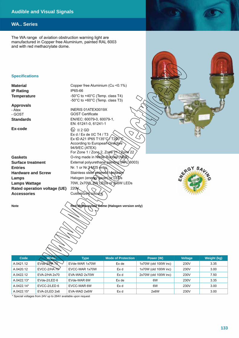
133
Specifications
Material Copper free Aluminium (Cu <0.1%)IP Rating IP65-66Temperature -50°C to +40°C (Temp. class T4)
-50°C to +60°C (Temp. class T3)Approvals- Atex- GOST
INERIS 01ATEX0019XGOST Certificate
Standards EN/IEC: 60079-0, 60079-1, EN: 61241-0, 61241-1
Ex-code II 2 GDEx d / Ex de IIC T4 / T3 Ex tD A21 IP65 T135°C / T200°CAccording to European Directive 94/9/EC (ATEX)For Zone 1 / Zone 2, Zone 21 / Zone 22
Gaskets O-ring made in Nitrile Rubber (NBR)Surface treatment External polyurethane painting (RAL 6003)Entries Nr. 1 or Nr.2 M25 entryHardware and Screw Stainless steel external hardwareLamps Halogen (energy saver) or LEDsLamps Wattage 70W, 2x70W, 6W LEDs or 2x6W LEDsRated operation voltage (UE) 220VAccessories Customized colours
Note Red Methacrylate Dome (Halogen version only)
The WA range of aviation obstruction warning light are manufactured in Copper free Aluminium, painted RAL 6003 and with red methacrylate dome.
WA.. Series
Audible and Visual Signals
Code Model Type Mode of Protection Power (W) Voltage Weight (kg)A.0421.12 EVde-2/HA 70 EVde-WAR 1x70W Ex de 1x70W (old 100W inc) 230V 3.35
A.0420.12 EVCC-2/HA 70 EVCC-WAR 1x70W Ex d 1x70W (old 100W inc) 230V 3.00
A.0422.12 EVA-2/HA 2x70 EVA-WAD 2x70W Ex d 2x70W (old 100W inc) 230V 7.50
A.0422.13* EVde-2/LED 6 EVde-WAR 6W Ex de 6W 230V 3.35
A.0422.14* EVCC-2/LED 6 EVCC-WAR 6W Ex d 6W 230V 3.00
A.0422.15* EVA-2/LED 2x6 EVA-WAD 2x6W Ex d 2x6W 230V 3.00* Special voltages from 24V up to 264V available upon request
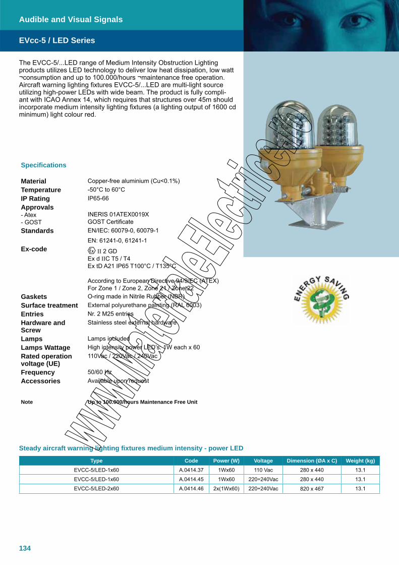
134
Steady aircraft warning lighting fixtures medium intensity - power LED
The EVCC-5/...LED range of Medium Intensity Obstruction Lighting products utilizes LED technology to deliver low heat dissipation, low watt ¬consumption and up to 100.000/hours ¬maintenance free operation. Aircraft warning lighting fixtures EVCC-5/...LED are multi-light source utilizing high-power LEDs with wide beam. The product is fully compli-ant with ICAO Annex 14, which requires that structures over 45m should incorporate medium intensity lighting fixtures (a lighting output of 1600 cd minimum) light colour red.
Specifications
Material Copper-free aluminium (Cu<0.1%)Temperature -50°C to 60°CIP Rating IP65-66Approvals- Atex- GOST
INERIS 01ATEX0019XGOST Certificate
Standards EN/IEC: 60079-0, 60079-1
EN: 61241-0, 61241-1Ex-code II 2 GD
Ex d IIC T5 / T4 Ex tD A21 IP65 T100°C / T135°C According to European Directive 94/9/EC (ATEX)For Zone 1 / Zone 2, Zone 21 / Zone 22
Gaskets O-ring made in Nitrile Rubber (NBR)Surface treatment External polyurethane painting (RAL 6003)Entries Nr. 2 M25 entriesHardware and Screw
Stainless steel external hardware
Lamps Lamps includedLamps Wattage High intensity power LED’s: 1W each x 60Rated operation voltage (UE)
110Vac / 220Vac / 240Vac
Frequency 50/60 HzAccessories Available upon request
Note Up to 100.000/hours Maintenance Free Unit
EVcc-5 / LED Series
Audible and Visual Signals
Type Code Power (W) Voltage Dimension (ØA x C) Weight (kg)EVCC-5/LED-1x60 A.0414.37 1Wx60 110 Vac 280 x 440 13.1
EVCC-5/LED-1x60 A.0414.45 1Wx60 220÷240Vac 280 x 440 13.1
EVCC-5/LED-2x60 A.0414.46 2x(1Wx60) 220÷240Vac 820 x 467 13.1

135
Plinthe en optionet entraxes de fixation
Vis de terre M5
Raccordement
EVcc-5 / LED Series
Audible and Visual Signals
Dimensions
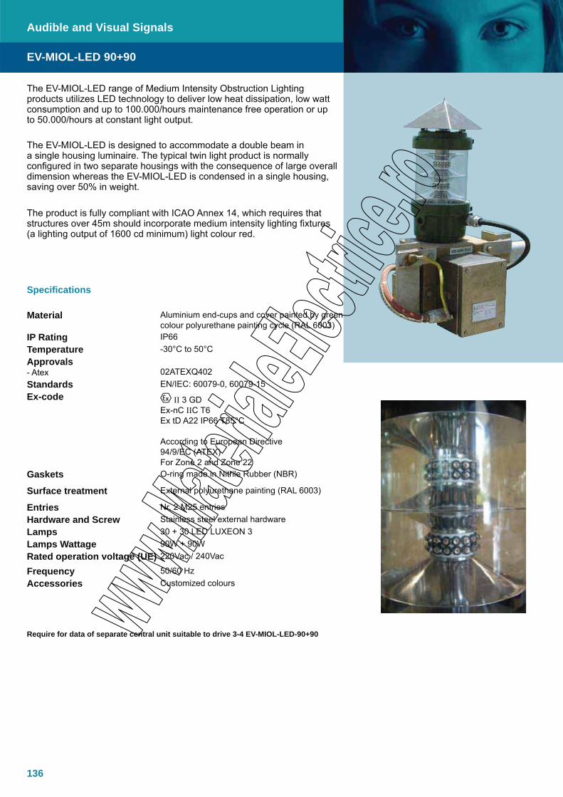
136
The EV-MIOL-LED range of Medium Intensity Obstruction Lighting products utilizes LED technology to deliver low heat dissipation, low watt consumption and up to 100.000/hours maintenance free operation or up to 50.000/hours at constant light output.
The EV-MIOL-LED is designed to accommodate a double beam in a single housing luminaire. The typical twin light product is normally configured in two separate housings with the consequence of large overall dimension whereas the EV-MIOL-LED is condensed in a single housing, saving over 50% in weight.
The product is fully compliant with ICAO Annex 14, which requires that structures over 45m should incorporate medium intensity lighting fixtures (a lighting output of 1600 cd minimum) light colour red.
EV-MIOL-LED 90+90
Audible and Visual Signals
Specifications
Material Aluminium end-cups and cover painted by green colour polyurethane painting cycle (RAL 6003)
IP Rating IP66Temperature -30°C to 50°CApprovals- Atex 02ATEXQ402Standards EN/IEC: 60079-0, 60079-15Ex-code II 3 GD
Ex-nC IIC T6Ex tD A22 IP66 T85°C
According to European Directive 94/9/EC (ATEX)For Zone 2 and Zone 22
Gaskets O-ring made in Nitrile Rubber (NBR)
Surface treatment External polyurethane painting (RAL 6003)
Entries Nr. 2 M25 entriesHardware and Screw Stainless steel external hardwareLamps 30 + 30 LED LUXEON 3 Lamps Wattage 90W + 90WRated operation voltage (UE) 220Vac / 240Vac
Frequency 50/60 HzAccessories Customized colours
Require for data of separate central unit suitable to drive 3-4 EV-MIOL-LED-90+90
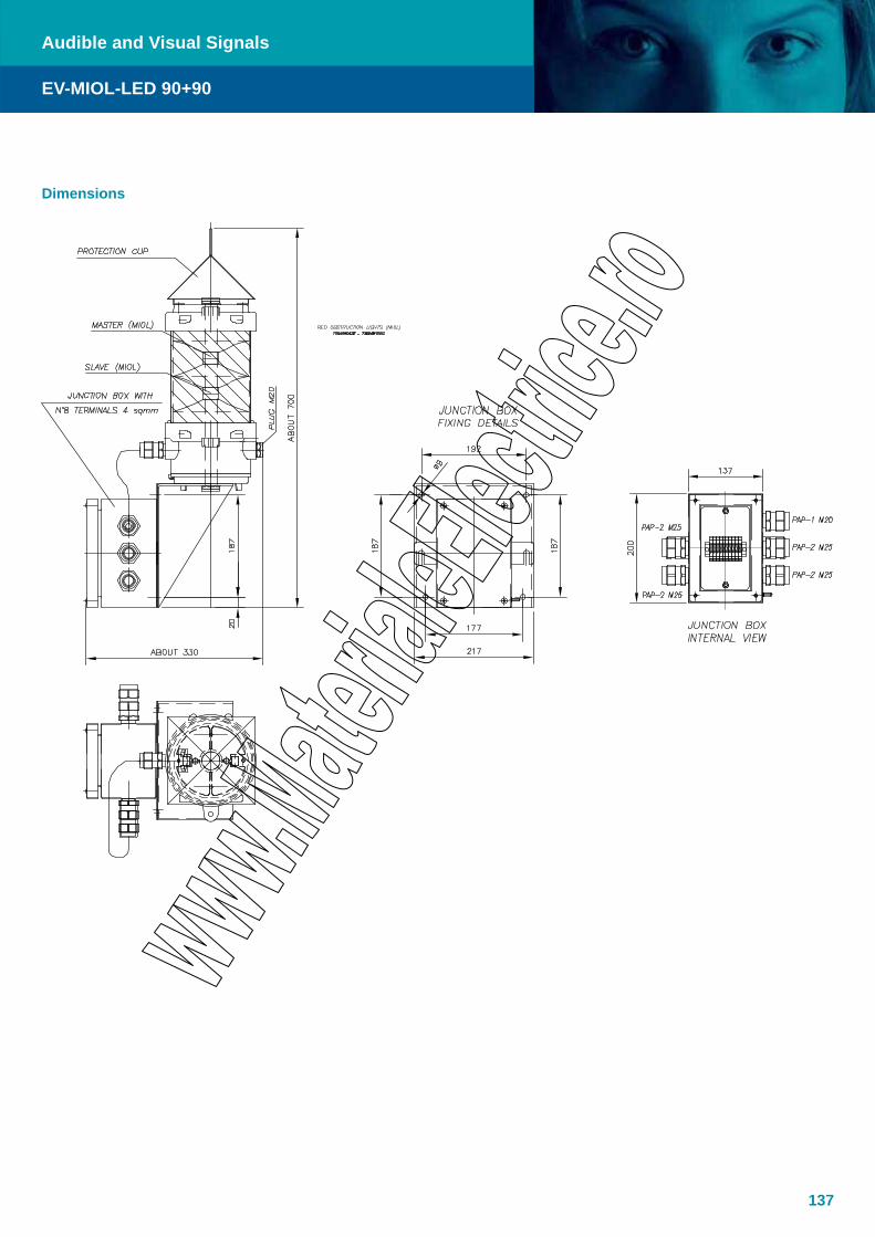
137
EV-MIOL-LED 90+90
Audible and Visual Signals
Dimensions

138
The TNDSP Ex d electronic speaker is configured with traditional mechanical bell sound. With no moving parts it is the ideal replacement for standard mechanical Ex protected alarms or bells.
Specifications
Material Antistatic polyamide, bracket in AISI 316LIP Rating IP66Operating temperature -20ºC to +40ºC Approvals - Atex Nemko 03ATEX1357Standards EN/IEC: 60079-0, 60079-1, 60079-7Ex-Code Ex des IIB + H2 T6 II 2 GEarthing Internal M4Entries 1xM20 + 1xM25 pluggedConnections 2.5mm² maxPower 25WPower consumption 19.6W (8W, 1kHz sine wave)Sound level P112 dBRated current Max 2 Amp.Operating voltage 24VDC (19.2 – 28VDC)EMC protection EN50082-2 / EN50081-2Upon request Other sound effectsColour Black
TNDSP-25 Ex bell
Audible and Visual Signals
Dimensions
Sound Characteristics for TNDSP-25-Ex bell

139
Audible and Visible Signals
The XAWS Ex e break-glass call-point for emergency or fire alarm. The call point is available with two modes of operation:
Automatic: The contact block is held in position by the glass. • The contact opens as soon as the glass is broken.Manual: The contact must be operated by the user once the • glass is broken.
Specifications
Material GRPIP Rating IP 65–66Temperature –20°C to +40°C (+50°C, +60°C)Approvals - Atex INERIS 03ATEX0122Standards EN/IEC: 60079-0, 60079-1, 60079-7, EN50281-1-1Ex-Code II 2 GD, Ex ed IIC T6 to T4 T85°C to T135°C
Complete Fire alarm stationAutomatic contact operation
Contact block type
NC ZBWE102
NO ZBWE101
NO+ NC ZBWE101+ ZBWE102
Reference XAWS111 XAWS121 XAWS151
Manual contact operation
Contact block type
NO ZBWE101
NC ZBWE102
NO+ NC ZBWE101 + ZBWE102
Reference XAWS211 XAWS221 XAWS251
Accessories and spare parts
Slow break contact block NO ZBWE101
NC ZBWE102
Glass XAWS901
Dimensions
XAWS

140

141
Lighting
EVde HID SeriesLighting fixtures for HID lamps, Ex de, Copper free Aluminium
EVde I/HA SeriesLighting fixtures for incandescent / halogen lamps, Ex de, Copper free Aluminium
RMS 540 SeriesFluorescent lamps, IP65, AISI 304
EVF-P SeriesFluorescent lamps, Ex d, end-cups in Copper free Aluminium
FL SeriesFloodlights, Ex de, Copper free Aluminium / AISI 316L
EVde-LED / EVde-PT SeriesSpot Lights, Ex de, Copper free Aluminium
EVA SeriesHand lamps for incandescent lamps, Ex d, Copper free Aluminium
EVcc-PR SeriesTank Lighting fixtures, Ex d, Copper free Aluminium
TNCLSLevel Gauges, Ex em, AISI 316L
TNXCXFloodlight, Ex e/de, Acid Resistant Steel
TNAMLFluorescent light, Ex me, Seawater resistant anodized aluminium
RMS 560 SeriesFluorescent lamps, Ex de, AISI 304
RMS 550 SeriesFluorescent lamps, Ex nA, AISI 304
EVF-P Endurance SeriesFluorescent lamps long life, Ex d, end-cups in Copper free Aluminium
142
143
145
149
153
155
157
160
162
164
166
167
168
169
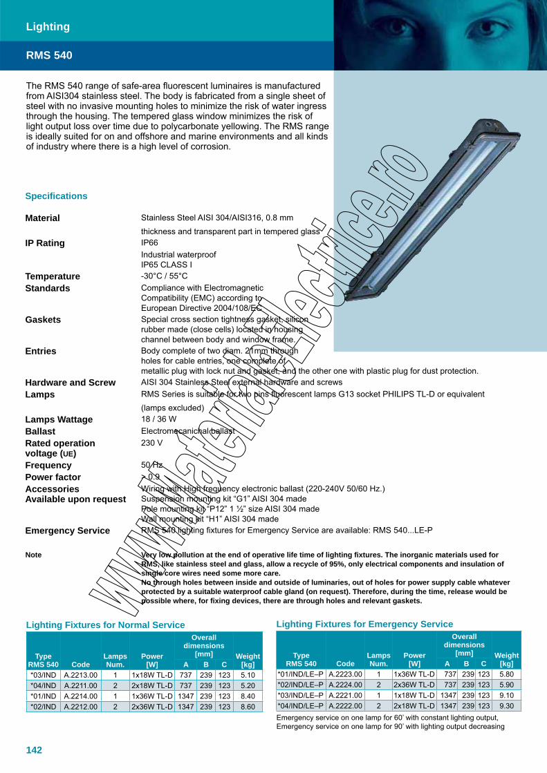
142
Specifications
Material Stainless Steel AISI 304/AISI316, 0.8 mm
thickness and transparent part in tempered glass IP Rating IP66
Industrial waterproofIP65 CLASS I
Temperature -30°C / 55°CStandards Compliance with Electromagnetic
Compatibility (EMC) according to European Directive 2004/108/EC
Gaskets Special cross section tightness gasket, silicon rubber made (close cells) located in housing channel between body and window frame.
Entries Body complete of two diam. 21mm through holes for cable entries, one complete of metallic plug with lock nut and gasket, and the other one with plastic plug for dust protection.
Hardware and Screw AISI 304 Stainless Steel external hardware and screwsLamps RMS Series is suitable for two pins fluorescent lamps G13 socket PHILIPS TL-D or equivalent
(lamps excluded)Lamps Wattage 18 / 36 WBallast Electromecanichal ballastRated operation voltage (UE)
230 V
Frequency 50 HzPower factor > 0.9AccessoriesAvailable upon request
Wiring with High frequency electronic ballast (220-240V 50/60 Hz.)Suspension mounting kit “G1” AISI 304 madePole mounting kit “P12” 1 ½” size AISI 304 madeWall mounting kit “H1” AISI 304 made
Emergency Service RMS 540 lighting fixtures for Emergency Service are available: RMS 540...LE-P
Note Very low pollution at the end of operative life time of lighting fixtures. The inorganic materials used for RMS, like stainless steel and glass, allow a recycle of 95%, only electrical components and insulation of single core wires need some more care.No through holes between inside and outside of luminaries, out of holes for power supply cable whatever protected by a suitable waterproof cable gland (on request). Therefore, during the time, release would be possible where, for fixing devices, there are through holes and relevant gaskets.
The RMS 540 range of safe-area fluorescent luminaires is manufactured from AISI304 stainless steel. The body is fabricated from a single sheet of steel with no invasive mounting holes to minimize the risk of water ingress through the housing. The tempered glass window minimizes the risk of light output loss over time due to polycarbonate yellowing. The RMS range is ideally suited for on and offshore and marine environments and all kinds of industry where there is a high level of corrosion.
RMS 540
Lighting
Lighting Fixtures for Normal Service
TypeRMS 540 Code
LampsNum.
Power[W]
Overall dimensions
[mm] Weight[kg]A B C
*03/IND A.2213.00 1 1x18W TL-D 737 239 123 5.10 *04/IND A.2211.00 2 2x18W TL-D 737 239 123 5.20 *01/IND A.2214.00 1 1x36W TL-D 1347 239 123 8.40 *02/IND A.2212.00 2 2x36W TL-D 1347 239 123 8.60
Lighting Fixtures for Emergency Service
TypeRMS 540 Code
LampsNum.
Power[W]
Overall dimensions
[mm] Weight[kg]A B C
*01/IND/LE–P A.2223.00 1 1x36W TL-D 737 239 123 5.80 *02/IND/LE–P A.2224.00 2 2x36W TL-D 737 239 123 5.90 *03/IND/LE–P A.2221.00 1 1x18W TL-D 1347 239 123 9.10 *04/IND/LE–P A.2222.00 2 2x18W TL-D 1347 239 123 9.30 Emergency service on one lamp for 60’ with constant lighting output, Emergency service on one lamp for 90’ with lighting output decreasing
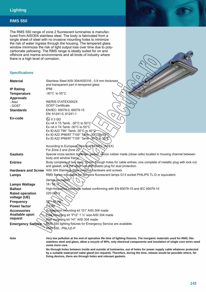
143
Lighting
The RMS 550 range of zone 2 fluorescent luminaires is manufac-tured from AISI304 stainless steel. The body is fabricated from a single sheet of steel with no invasive mounting holes to minimize the risk of water ingress through the housing. The tempered glass window minimizes the risk of light output loss over time due to poly-carbonate yellowing. The RMS range is ideally suited for on and offshore and marine environments and all kinds of industry where there is a high level of corrosion.
Specifications
Material Stainless Steel AISI 304/AISI316 , 0.8 mm thickness and transparent part in tempered glass
IP Rating IP66Temperature -30°C to 55°CApprovals- Atex- GOST
INERIS 01ATEX3002XGOST Certificate
Standards EN/IEC: 60079-0, 60079-15EN: 61241-0, 61241-1
Ex-code II 3 GDEx nA II T5 Tamb. -30°C to 50°CEx nA II T4 Tamb -30°C to 55°CEx tD A22 T90° Tamb -30°C to 40°CEx tD A22 IP66/67 T100° Tamb -30°C to 50°CEx tD A22 IP66/67 T105° Tamb -30°C to 55°C
According to European Directive 94/9/EC (ATEX)For Zone 2 and Zone 22
Gaskets Special cross section tightness gasket, silicon rubber made (close cells) located in housing channel between body and window frame.
Entries Body complete of two diam. 21mm through holes for cable entries, one complete of metallic plug with lock nut and gasket, and the other one with plastic plug for dust protection.
Hardware and Screw AISI 304 Stainless Steel external hardware and screwsLamps RMS Series is suitable for two pins fluorescent lamps G13 socket PHILIPS TL-D or equivalent.
(lamps excluded)Lamps Wattage 18 / 36 WBallast High-frequency electronic ballast conforming with EN 60079-15 and IEC 60079-15Rated operation voltage (UE)
220-240 V
Frequency 50 ÷ 60 HzPower factor > 0.95AccessoriesAvailable upon request
Suspension mounting kit “G1” AISI 304 madePole mounting kit “P12” 1 ½” size AISI 304 madeWall mounting kit “H1” AISI 304 made
Emergency Service RMS 550 lighting fixtures for Emergency Service are available:RMS 550...PNL/LE-P
Note Very low pollution at the end of operative life time of lighting fixtures. The inorganic materials used for RMS, like stainless steel and glass, allow a recycle of 95%, only electrical components and insulation of single core wires need some more care.No through holes between inside and outside of luminaries, out of holes for power supply cable whatever protected by a suitable waterproof cable gland (on request). Therefore, during the time, release would be possible where, for fixing devices, there are through holes and relevant gaskets.
RMS 550

144
Lighting
RMS 550 Lighting Fixtures for Normal ServiceTYPE
RMS 550CODE LAMPS
Num.POWER
[W]Overall dimensions [mm] WEIGHT
[kg]A B C* 03/PNL A.2205.00 1 1x18W TL-D 737 239 123 5.10 * 04/PNL A.2201.00 2 2x18W TL-D 737 239 123 5.20 * 01/PNL A.2206.00 1 1x36W TL-D 1347 239 123 8.40 * 02/PNL A.2202.00 2 2x36W TL-D 1347 239 123 8.60
RMS 550 Lighting Fixtures for Emergency ServiceTYPE
RMS 550 CODEPOWER
[W]Overall dimensions [mm] WEIGHT
[kg]A B C* 03/PNL/LE-P A.2236.00 1 1x18W TL-D 737 239 123 5.10 * 04/PNL/LE-P A.2283.00 2 2x18W TL-D 737 239 123 5.20 * 01/PNL/LE-P A.2235.00 1 1x36W TL-D 1347 239 123 8.40 * 02/PNL/LE-P A.2234.00 2 2x36W TL-D 1347 239 123 8.60
Emergency service on one lamp for 60’ with constant lighting output, Emergency service on one lamp for 90’ with lighting output decreasing
RMS 550
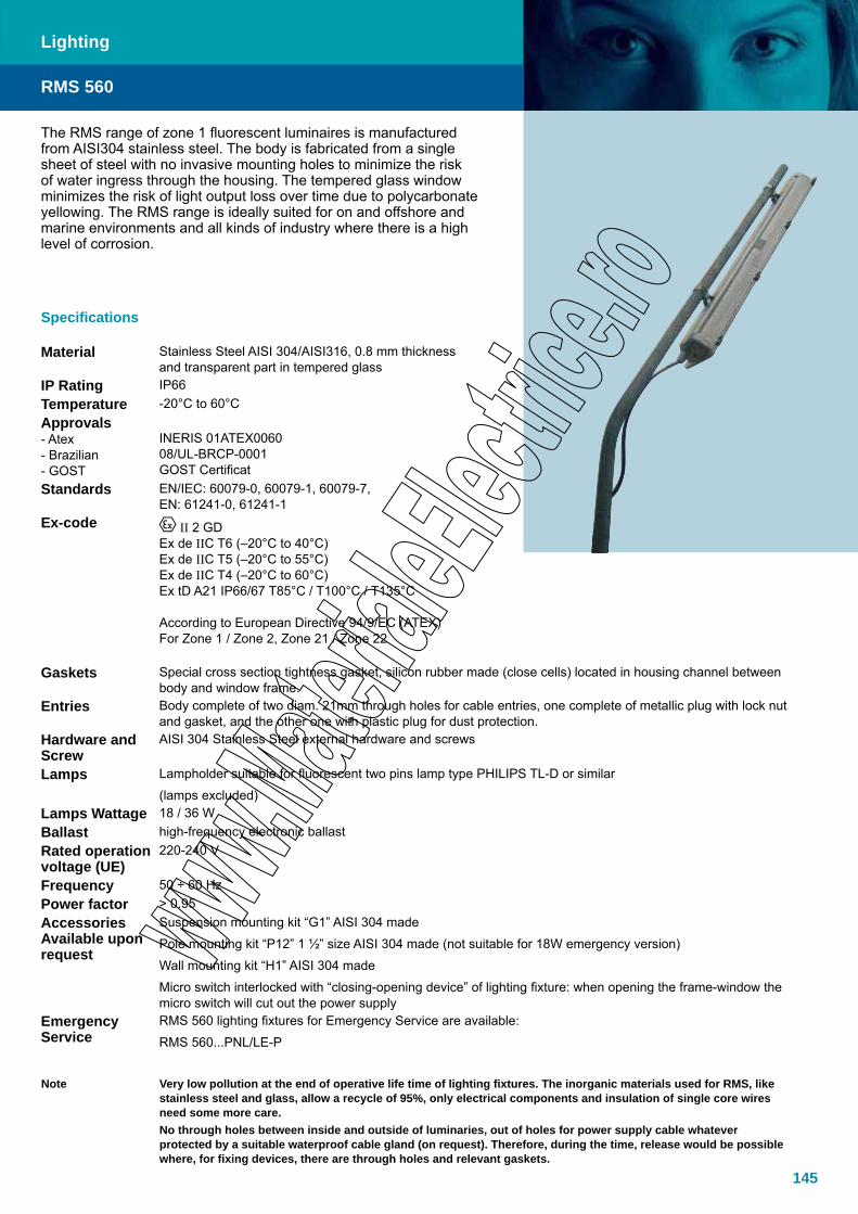
145
Lighting
The RMS range of zone 1 fluorescent luminaires is manufactured from AISI304 stainless steel. The body is fabricated from a single sheet of steel with no invasive mounting holes to minimize the risk of water ingress through the housing. The tempered glass window minimizes the risk of light output loss over time due to polycarbonate yellowing. The RMS range is ideally suited for on and offshore and marine environments and all kinds of industry where there is a high level of corrosion.
Specifications
Material Stainless Steel AISI 304/AISI316, 0.8 mm thickness and transparent part in tempered glass
IP Rating IP66Temperature -20°C to 60°CApprovals- Atex- Brazilian- GOST
INERIS 01ATEX006008/UL-BRCP-0001GOST Certificat
Standards EN/IEC: 60079-0, 60079-1, 60079-7, EN: 61241-0, 61241-1
Ex-code II 2 GDEx de IIC T6 (–20°C to 40°C)Ex de IIC T5 (–20°C to 55°C)Ex de IIC T4 (–20°C to 60°C)Ex tD A21 IP66/67 T85°C / T100°C / T135°C
According to European Directive 94/9/EC (ATEX)For Zone 1 / Zone 2, Zone 21 / Zone 22
Gaskets Special cross section tightness gasket, silicon rubber made (close cells) located in housing channel between body and window frame.
Entries Body complete of two diam. 21mm through holes for cable entries, one complete of metallic plug with lock nut and gasket, and the other one with plastic plug for dust protection.
Hardware and Screw
AISI 304 Stainless Steel external hardware and screws
Lamps Lampholder suitable for fluorescent two pins lamp type PHILIPS TL-D or similar
(lamps excluded)Lamps Wattage 18 / 36 WBallast high-frequency electronic ballastRated operation voltage (UE)
220-240 V
Frequency 50 ÷ 60 HzPower factor > 0.95AccessoriesAvailable upon request
Suspension mounting kit “G1” AISI 304 made
Pole mounting kit “P12” 1 ½” size AISI 304 made (not suitable for 18W emergency version)
Wall mounting kit “H1” AISI 304 made
Micro switch interlocked with “closing-opening device” of lighting fixture: when opening the frame-window the micro switch will cut out the power supply
Emergency Service
RMS 560 lighting fixtures for Emergency Service are available:
RMS 560...PNL/LE-P
Note Very low pollution at the end of operative life time of lighting fixtures. The inorganic materials used for RMS, like stainless steel and glass, allow a recycle of 95%, only electrical components and insulation of single core wires need some more care.No through holes between inside and outside of luminaries, out of holes for power supply cable whatever protected by a suitable waterproof cable gland (on request). Therefore, during the time, release would be possible where, for fixing devices, there are through holes and relevant gaskets.
RMS 560
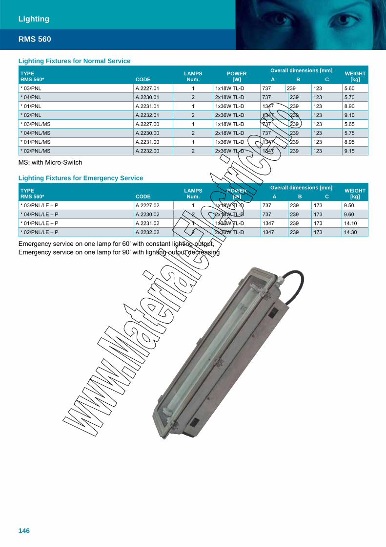
146
Lighting
RMS 560
Lighting Fixtures for Normal Service
TYPERMS 560* CODE
LAMPSNum.
POWER[W]
Overall dimensions [mm] WEIGHT[kg]A B C
* 03/PNL A.2227.01 1 1x18W TL-D 737 239 123 5.60
* 04/PNL A.2230.01 2 2x18W TL-D 737 239 123 5.70
* 01/PNL A.2231.01 1 1x36W TL-D 1347 239 123 8.90
* 02/PNL A.2232.01 2 2x36W TL-D 1347 239 123 9.10
* 03/PNL/MS A.2227.00 1 1x18W TL-D 737 239 123 5.65
* 04/PNL/MS A.2230.00 2 2x18W TL-D 737 239 123 5.75
* 01/PNL/MS A.2231.00 1 1x36W TL-D 1347 239 123 8.95
* 02/PNL/MS A.2232.00 2 2x36W TL-D 1347 239 123 9.15
MS: with Micro-Switch
Lighting Fixtures for Emergency Service
TYPERMS 560* CODE
LAMPSNum.
POWER[W]
Overall dimensions [mm] WEIGHT[kg]A B C
* 03/PNL/LE – P A.2227.02 1 1x18W TL-D 737 239 173 9.50
* 04/PNL/LE – P A.2230.02 2 2x18W TL-D 737 239 173 9.60
* 01/PNL/LE – P A.2231.02 1 1x36W TL-D 1347 239 173 14.10
* 02/PNL/LE – P A.2232.02 2 2x36W TL-D 1347 239 173 14.30
Emergency service on one lamp for 60’ with constant lighting output, Emergency service on one lamp for 90’ with lighting output decreasing
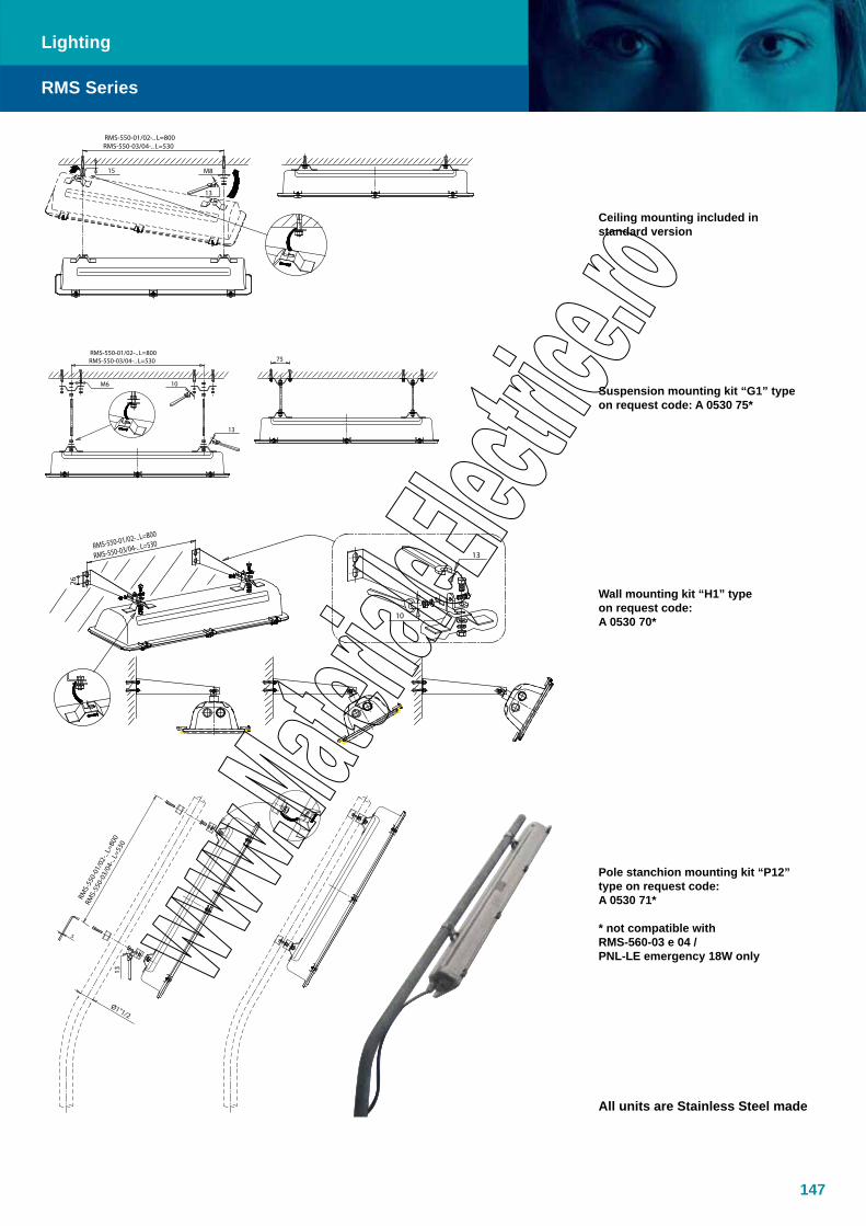
147
Lighting
RMS Series
Suspension mounting kit “G1” type on request code: A 0530 75*
Pole stanchion mounting kit “P12” type on request code: A 0530 71*
* not compatible withRMS-560-03 e 04 / PNL-LE emergency 18W only
Ceiling mounting included in standard version
Wall mounting kit “H1” type on request code: A 0530 70*
All units are Stainless Steel made

148
Lighting
RMS Series
RMS lighting fixtures mounting path

149
Features10 years operational warranty gives low lifecycle cost*• 100% encapsulated.• M• aintenance free solution requiring only visual inspection from an Ex point of viewEasy and flexible installation• Seawater resistant • anodized aluminumTempered glass • Fully recyclable• High light efficiency (80%)• Available with 2x18W / 2x36W / 2x58W lamps• Optional incorporated battery powered • LED emergency lightingSealed-for-life concept• Fit and forget• Patented design• Vibration test•
Standard: IEC60721-2-3 Ed 1.0 and IEC68-2-6 Frequency range: 1 - 150 Hz Amplitude: 5mm (1 to 10 Hz) Acceleration: 2 gn (10 to 150 Hz) Sweep rate: 1 octave per minute # sweep cycles: 10 # directions: 3
General specifications:Modes of protection Ex e mb, Ex tD A21ATEX classification Group II Category 2 G DZones 1, 2, 21, 22Applied standards EN/IEC: 60079-0, 60079-7, 60079-18 EN: 61241-0, 61241-1Approvals - Atex KEMA 08ATEX0163Ex code II 2 G Ex e mb II T6 II 2 D Ex tD A21 IP66 T80°CInspection Visual inspection in accordance with EN/IEC 60079-17
Product specifications:Housing Seawater resistant anodized (25 micron) aluminium with tempered glassLamps Pre-mounted long life lamps, colour 4000KIP Rating IP66Temperature range -20°C to +55°CVoltage 220-264VAC 50/60HzElectrical connection 0.5-6mm2 spring terminals through integrated external junction box (sealed by resin)Entries 2 x Ø25 mm cable gland entries. One plugged.Ballast Electronic with end of life protectionMounting 2 x adjustable brackets on guidance rail for easy and quick installationLED (Em. lighting versions) 90 minutes battery backup
Options (upon request, minimum quatities may apply):Voltage 110/120VAC, 50/60 Hz (only for 2x18W and 2x36W)Lamps Colour 3000KElectrical connection 8 metre permanent flying lead, braidedLED Emergency lighting 180 minute back-up 4 LEDs to meet requirements of IMO/DNV-OS-A101Glass For use in accordance with HACCP environment (food industry)Wiring Through wiring (each end of the luminaire)Other area classifications Zone II, Ex n, 3 GD (TNAMLC...) or safe area version (TNAMLD...)
AccessoriesMounting brackets Pole and ceiling mounting bracketsSafety wire For installation into a fixing arrangement on the light fittingCable Gland Suitable rated cable glands can be supplied with the light fittingManned/Unmanned facilities “Black start” function for manned/unmanned functionalityIndoor ceiling installation Frame for resessed installation
Lighting
TNAML
*Conditions apply
Emergency version
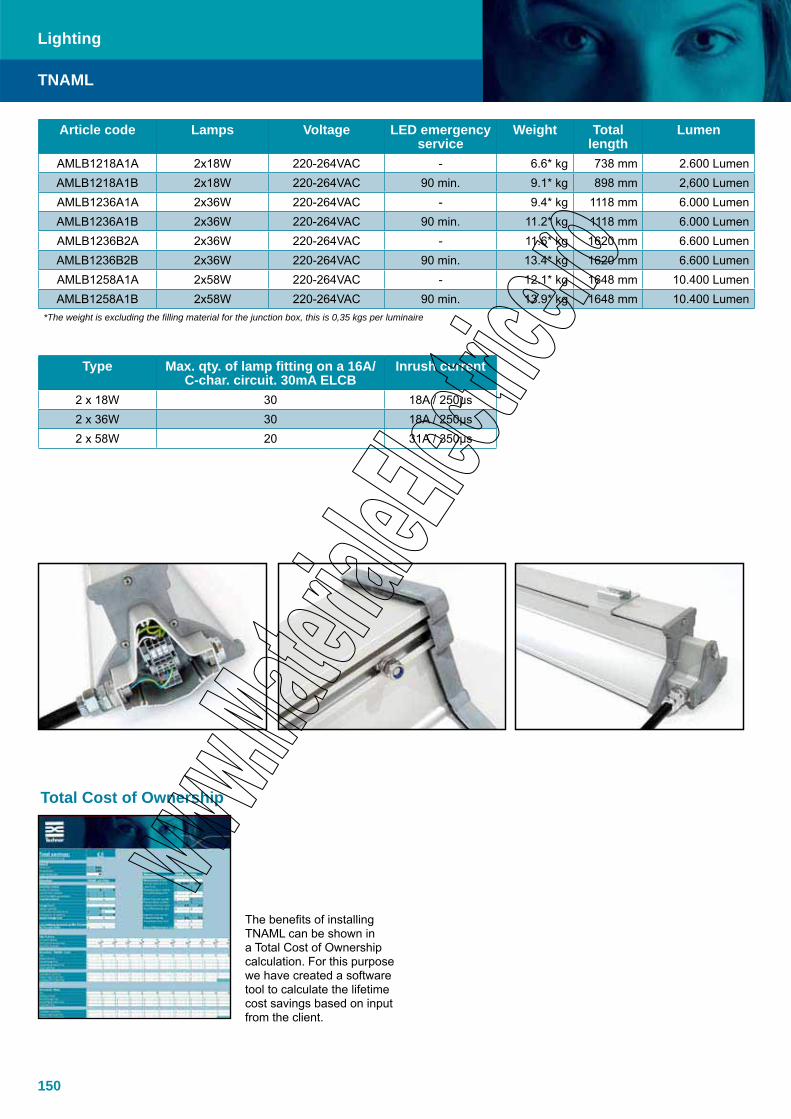
150
Total Cost of Ownership
The benefits of installing TNAML can be shown in a Total Cost of Ownership calculation. For this purpose we have created a software tool to calculate the lifetime cost savings based on input from the client.
Lighting
TNAML
Article code Lamps Voltage LED emergency service
Weight Total length
Lumen
AMLB1218A1A 2x18W 220-264VAC - 6.6* kg 738 mm 2.600 LumenAMLB1218A1B 2x18W 220-264VAC 90 min. 9.1* kg 898 mm 2,600 LumenAMLB1236A1A 2x36W 220-264VAC - 9.4* kg 1118 mm 6.000 LumenAMLB1236A1B 2x36W 220-264VAC 90 min. 11.2* kg 1118 mm 6.000 LumenAMLB1236B2A 2x36W 220-264VAC - 11.6* kg 1620 mm 6.600 LumenAMLB1236B2B 2x36W 220-264VAC 90 min. 13.4* kg 1620 mm 6.600 LumenAMLB1258A1A 2x58W 220-264VAC - 12.1* kg 1648 mm 10.400 LumenAMLB1258A1B 2x58W 220-264VAC 90 min. 13.9* kg 1648 mm 10.400 Lumen
*The weight is excluding the filling material for the junction box, this is 0,35 kgs per luminaire
Type Max. qty. of lamp fitting on a 16A/C-char. circuit. 30mA ELCB
Inrush current
2 x 18W 30 18A / 250μs2 x 36W 30 18A / 250μs2 x 58W 20 31A / 350μs
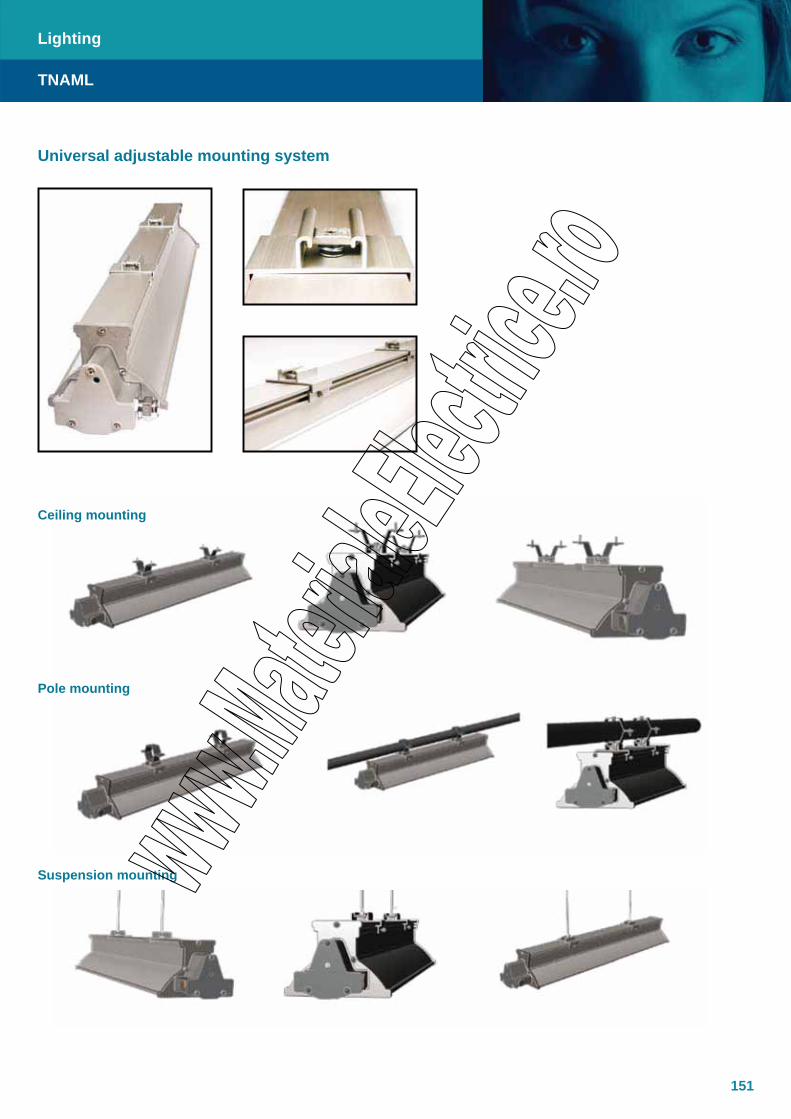
151
Universal adjustable mounting system
Suspension mounting
Pole mounting
Ceiling mounting
Lighting
TNAML
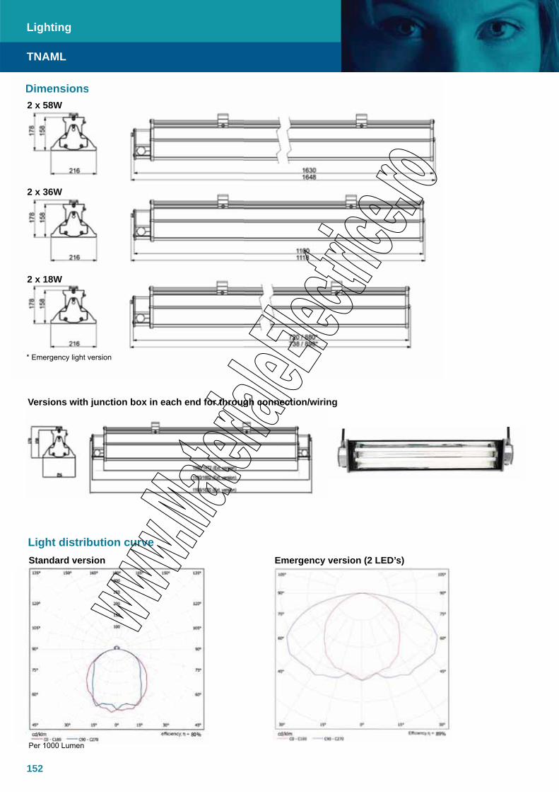
152
DimensionsDimensions2 x 58W
2 x 36W
2 x 18W
Light distribution curve
Per 1000 Lumen
* Emergency light version
Standard version Emergency version (2 LED’s)
Versions with junction box in each end for through connection/wiringVersions with junction box in each end for through connection/wirin
Lighting
TNAML
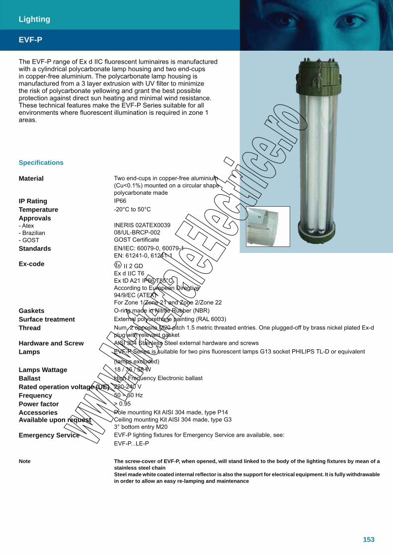
153
The EVF-P range of Ex d IIC fluorescent luminaires is manufactured with a cylindrical polycarbonate lamp housing and two end-cups in copper-free aluminium. The polycarbonate lamp housing is manufactured from a 3 layer extrusion with UV filter to minimize the risk of polycarbonate yellowing and grant the best possible protection against direct sun heating and minimal wind resistance. These technical features make the EVF-P Series suitable for all environments where fluorescent illumination is required in zone 1 areas.
Specifications
Material Two end-cups in copper-free aluminium (Cu<0.1%) mounted on a circular shape polycarbonate made
IP Rating IP66Temperature -20°C to 50°CApprovals- Atex- Brazilian- GOST
INERIS 02ATEX003908/UL-BRCP-002GOST Certificate
Standards EN/IEC: 60079-0, 60079-1 EN: 61241-0, 61241-1
Ex-code II 2 GDEx d IIC T6 Ex tD A21 IP66 T85°CAccording to European Directive 94/9/EC (ATEX)For Zone 1/Zone 21 and Zone 2/Zone 22
Gaskets O-ring made in Nitrile Rubber (NBR)Surface treatment External polyurethane painting (RAL 6003)Thread Num. 2 opposite M20 pitch 1.5 metric threated entries. One plugged-off by brass nickel plated Ex-d
plug with relevant gasketHardware and Screw AISI 304 Stainless Steel external hardware and screwsLamps EVF-P Series is suitable for two pins fluorescent lamps G13 socket PHILIPS TL-D or equivalent
(lamps excluded)Lamps Wattage 18 / 36 / 58 WBallast High Frequency Electronic ballastRated operation voltage (UE) 220-240 VFrequency 50 ÷ 60 HzPower factor > 0.95AccessoriesAvailable upon request
Pole mounting Kit AISI 304 made, type P14Ceiling mounting Kit AISI 304 made, type G33° bottom entry M20
Emergency Service EVF-P lighting fixtures for Emergency Service are available, see:EVF-P...LE-P
Note The screw-cover of EVF-P, when opened, will stand linked to the body of the lighting fixtures by mean of a stainless steel chainSteel made white coated internal reflector is also the support for electrical equipment. It is fully withdrawable in order to allow an easy re-lamping and maintenance
EVF-P
Lighting
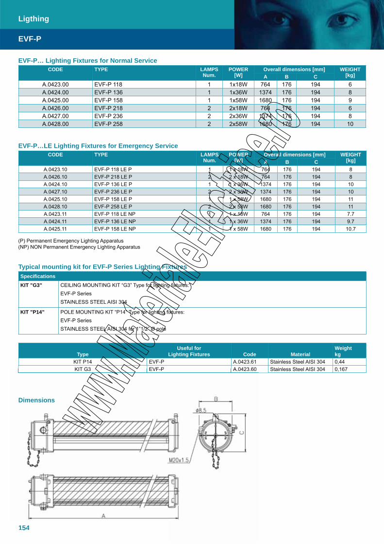
154
EVF-P… Lighting Fixtures for Normal ServiceCODE TYPE LAMPS
Num.POWER
[W]Overall dimensions [mm] WEIGHT
[kg]A B CA.0423.00 EVF-P 118 1 1x18W 764 176 194 6 A.0424.00 EVF-P 136 1 1x36W 1374 176 194 8 A.0425.00 EVF-P 158 1 1x58W 1680 176 194 9 A.0426.00 EVF-P 218 2 2x18W 764 176 194 6 A.0427.00 EVF-P 236 2 2x36W 1374 176 194 8 A.0428.00 EVF-P 258 2 2x58W 1680 176 194 10
EVF-P…LE Lighting Fixtures for Emergency ServiceCODE TYPE LAMPS
Num.POWER
[W]Overall dimensions [mm] WEIGHT
[kg]A B CA.0423.10 EVF-P 118 LE P 1 1 x 18W 764 176 194 8 A.0426.10 EVF-P 218 LE P 2 2 x 18W 764 176 194 8 A.0424.10 EVF-P 136 LE P 1 1 x 36W 1374 176 194 10 A.0427.10 EVF-P 236 LE P 2 2 x 36W 1374 176 194 10 A.0425.10 EVF-P 158 LE P 1 1 x 58W 1680 176 194 11 A.0428.10 EVF-P 258 LE P 2 2 x 58W 1680 176 194 11 A.0423.11 EVF-P 118 LE NP 1 1 x 18W 764 176 194 7.7 A.0424.11 EVF-P 136 LE NP 1 1 x 36W 1374 176 194 9.7 A.0425.11 EVF-P 158 LE NP 1 1 x 58W 1680 176 194 10.7
(P) Permanent Emergency Lighting Apparatus(NP) NON Permanent Emergency Lighting Apparatus
Typical mounting kit for EVF-P Series Lighting FixturesSpecificationsKIT ”G3” CEILING MOUNTING KIT “G3” Type for lighting fixtures:
EVF-P SeriesSTAINLESS STEEL AISI 304
KIT ”P14” POLE MOUNTING KIT “P14” Type for lighting fixtures:EVF-P SeriesSTAINLESS STEEL AISI 304 for 1”1/2” Ø pole
TypeUseful for
Lighting Fixtures Code MaterialWeightkg
KIT P14 EVF-P A.0423.61 Stainless Steel AISI 304 0,44KIT G3 EVF-P A.0423.60 Stainless Steel AISI 304 0,167
EVF-P
Ligthing
154
KIT G3 EVF-P A.0423.60
Dimensions
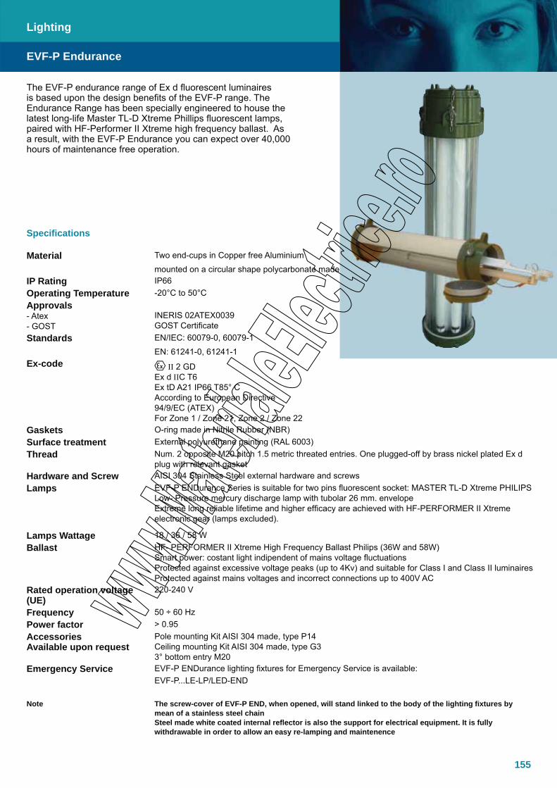
155
The EVF-P endurance range of Ex d fluorescent luminaires is based upon the design benefits of the EVF-P range. The Endurance Range has been specially engineered to house the latest long-life Master TL-D Xtreme Phillips fluorescent lamps, paired with HF-Performer II Xtreme high frequency ballast. As a result, with the EVF-P Endurance you can expect over 40,000 hours of maintenance free operation.
Specifications
Material Two end-cups in Copper free Aluminium
mounted on a circular shape polycarbonate madeIP Rating IP66Operating Temperature -20°C to 50°CApprovals- Atex- GOST
INERIS 02ATEX0039GOST Certificate
Standards EN/IEC: 60079-0, 60079-1
EN: 61241-0, 61241-1Ex-code II 2 GD
Ex d IIC T6 Ex tD A21 IP66 T85° CAccording to European Directive 94/9/EC (ATEX)For Zone 1 / Zone 21, Zone 2 / Zone 22
Gaskets O-ring made in Nitrile Rubber (NBR)Surface treatment External polyurethane painting (RAL 6003)Thread Num. 2 opposite M20 pitch 1.5 metric threated entries. One plugged-off by brass nickel plated Ex d
plug with relevant gasketHardware and Screw AISI 304 Stainless Steel external hardware and screwsLamps EVF-P ENDurance Series is suitable for two pins fluorescent socket: MASTER TL-D Xtreme PHILIPS
Low- Pressure mercury discharge lamp with tubolar 26 mm. envelopeExtreme long reliable lifetime and higher efficacy are achieved with HF-PERFORMER II Xtreme electronic gear (lamps excluded).
Lamps Wattage 18 / 36 / 58 WBallast HF- PERFORMER II Xtreme High Frequency Ballast Philips (36W and 58W)
Smart power: costant light indipendent of mains voltage fluctuationsProtected against excessive voltage peaks (up to 4Kv) and suitable for Class I and Class II luminairesProtected against mains voltages and incorrect connections up to 400V AC
Rated operation voltage (UE)
220-240 V
Frequency 50 ÷ 60 HzPower factor > 0.95AccessoriesAvailable upon request
Pole mounting Kit AISI 304 made, type P14Ceiling mounting Kit AISI 304 made, type G33° bottom entry M20
Emergency Service EVF-P ENDurance lighting fixtures for Emergency Service is available:EVF-P...LE-LP/LED-END
Note The screw-cover of EVF-P END, when opened, will stand linked to the body of the lighting fixtures by mean of a stainless steel chainSteel made white coated internal reflector is also the support for electrical equipment. It is fully withdrawable in order to allow an easy re-lamping and maintenence
EVF-P Endurance
Lighting
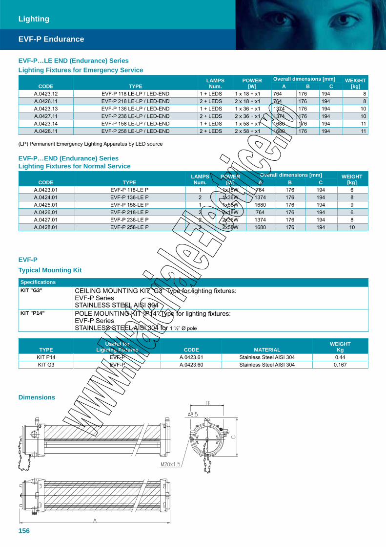
156
EVF-P Endurance
Lighting
EVF-PTypical Mounting Kit
SpecificationsKIT ”G3” CEILING MOUNTING KIT “G3” Type for lighting fixtures:
EVF-P SeriesSTAINLESS STEEL AISI 304
KIT ”P14” POLE MOUNTING KIT “P14” Type for lighting fixtures:EVF-P SeriesSTAINLESS STEEL AISI 304 for 1 ½” Ø pole
TYPEUseful for
Lighting Fixtures CODE MATERIALWEIGHT
KgKIT P14 EVF-P A.0423.61 Stainless Steel AISI 304 0.44KIT G3 EVF-P A.0423.60 Stainless Steel AISI 304 0.167
EVF-P…END (Endurance) SeriesLighting Fixtures for Normal Service
CODE TYPELAMPSNum.
POWER[W]
Overall dimensions [mm] WEIGHT[kg]A B C
A.0423.01 EVF-P 118-LE P 1 1x18W 764 176 194 6A.0424.01 EVF-P 136-LE P 2 1x36W 1374 176 194 8A.0425.01 EVF-P 158-LE P 1 1x58W 1680 176 194 9A.0426.01 EVF-P 218-LE P 2 2x18W 764 176 194 6A.0427.01 EVF-P 236-LE P 2 2x36W 1374 176 194 8A.0428.01 EVF-P 258-LE P 2 2x58W 1680 176 194 10
EVF-P…LE END (Endurance) SeriesLighting Fixtures for Emergency Service
CODE TYPELAMPSNum.
POWER[W]
Overall dimensions [mm] WEIGHT[kg]A B C
A.0423.12 EVF-P 118 LE-LP / LED-END 1 + LEDS 1 x 18 + x1 764 176 194 8 A.0426.11 EVF-P 218 LE-LP / LED-END 2 + LEDS 2 x 18 + x1 764 176 194 8 A.0423.13 EVF-P 136 LE-LP / LED-END 1 + LEDS 1 x 36 + x1 1374 176 194 10 A.0427.11 EVF-P 236 LE-LP / LED-END 2 + LEDS 2 x 36 + x1 1374 176 194 10 A.0423.14 EVF-P 158 LE-LP / LED-END 1 + LEDS 1 x 58 + x1 1680 176 194 11 A.0428.11 EVF-P 258 LE-LP / LED-END 2 + LEDS 2 x 58 + x1 1680 176 194 11
(LP) Permanent Emergency Lighting Apparatus by LED source
Dimensions
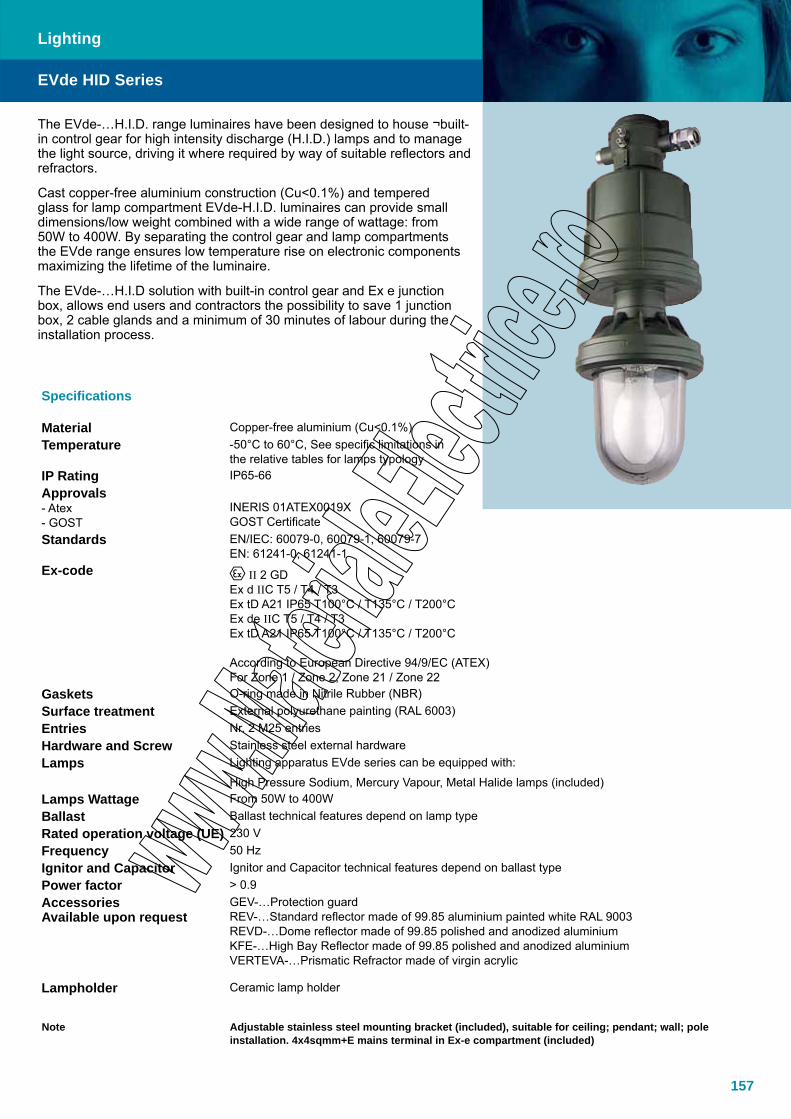
157
The EVde-…H.I.D. range luminaires have been designed to house ¬built-in control gear for high intensity discharge (H.I.D.) lamps and to manage the light source, driving it where required by way of suitable reflectors and refractors.
Cast copper-free aluminium construction (Cu<0.1%) and tempered glass for lamp compartment EVde-H.I.D. luminaires can provide small dimensions/low weight combined with a wide range of wattage: from 50W to 400W. By separating the control gear and lamp compartments the EVde range ensures low temperature rise on electronic components maximizing the lifetime of the luminaire.
The EVde-…H.I.D solution with built-in control gear and Ex e junction box, allows end users and contractors the possibility to save 1 junction box, 2 cable glands and a minimum of 30 minutes of labour during the installation process.
Specifications
Material Copper-free aluminium (Cu<0.1%)Temperature -50°C to 60°C, See specific limitations in
the relative tables for lamps typologyIP Rating IP65-66Approvals- Atex- GOST
INERIS 01ATEX0019XGOST Certificate
Standards EN/IEC: 60079-0, 60079-1, 60079-7 EN: 61241-0, 61241-1
Ex-code II 2 GDEx d IIC T5 / T4 / T3 Ex tD A21 IP65 T100°C / T135°C / T200°CEx de IIC T5 / T4 / T3Ex tD A21 IP65 T100°C / T135°C / T200°C
According to European Directive 94/9/EC (ATEX)For Zone 1 / Zone 2, Zone 21 / Zone 22
Gaskets O-ring made in Nitrile Rubber (NBR)Surface treatment External polyurethane painting (RAL 6003)Entries Nr. 2 M25 entriesHardware and Screw Stainless steel external hardwareLamps Lighting apparatus EVde series can be equipped with:
High Pressure Sodium, Mercury Vapour, Metal Halide lamps (included)Lamps Wattage From 50W to 400WBallast Ballast technical features depend on lamp typeRated operation voltage (UE) 230 V Frequency 50 HzIgnitor and Capacitor Ignitor and Capacitor technical features depend on ballast typePower factor > 0.9AccessoriesAvailable upon request
GEV-…Protection guardREV-…Standard reflector made of 99.85 aluminium painted white RAL 9003REVD-…Dome reflector made of 99.85 polished and anodized aluminiumKFE-…High Bay Reflector made of 99.85 polished and anodized aluminiumVERTEVA-…Prismatic Refractor made of virgin acrylic
Lampholder Ceramic lamp holder
Note Adjustable stainless steel mounting bracket (included), suitable for ceiling; pendant; wall; pole installation. 4x4sqmm+E mains terminal in Ex-e compartment (included)
EVde HID Series
Lighting

158
Lighting
High Pressure Sodium (NA)TYPE CODE LAMP W LAMP TYPE WEIGHT kg TEMP. CLASS
EVde-2/NA-B 50 A.0405.60 50 High Pressure Sodium 6.00 T4*EVde-2/NA-B 70 A.0405.61 70 High Pressure Sodium 6.00 T4*EVde-3/NA-B 50 A.0405.68 50 High Pressure Sodium v7.40 T4EVde-3/NA-B 70 9.0801.55 70 High Pressure Sodium 7.40 T4EVde-4/NA-B 100 A.0405.62 100 High Pressure Sodium 7.60 T3EVde-4/NA-B 150 A.0405.63 150 High Pressure Sodium 8.40 T3EVde-4/NA-B 250 A.0405.64 250 High Pressure Sodium 15.00 T3 Tamb. -20°C/40°CEVde-5/NA-B 250 A.0405.66 250 High Pressure Sodium 16.70 T4 Tamb. -20°C/40°C
T3 Tamb. -20°C/60°CEVde-5/NA-B 400 A.0405.67 400 High Pressure Sodium 18.00 T3 Tamb. -20°C/60°C
* Lamp with built-in glow-discharge ignitor
Mercury Vapour (HG)TYPE CODE LAMP W LAMP TYPE WEIGHT kg TEMP. CLASSEVde-2/HG-B 50 A.0405.51 50 Mercury Vapour 6.00 T4EVde-2/HG-B 80 A.0405.52 80 Mercury Vapour 6.00 T4EVde-3/HG-B 125 A.0405.54 125 Mercury Vapour 7.40 T3EVde-4/HG-B 175* A.0405.55 175 Mercury Vapour 8.30 T3Evde-4/HG-B 250 A.0405.56 250 Mercury Vapour 14.80 T3 Tamb. -20°C / 40°CEvde-5/HG-B 250 A.0405.58 250 Mercury Vapour 15.70 T4 Tamb. -20°C / 40°C
T3 Tamb. -20°C / 60°CEvde-5/HG-B 400 A.0405.59 400 Mercury Vapour 16.50 T3 Tamb. -20°C / 60°C
* On request
Metal Halide (IM)TYPE CODE LAMP W LAMP TYPE WEIGHT kg TEMP. CLASSA.0405.75 EVde-3/IM-B 70 70 Metal Halide 7.40 T4A.0405.76 EVde-4/IM-B 100 100 Metal Halide 7.60 T4A.0405.77 EVde-4/IM-B 150 150 Metal Halide 8.40 T4A.0405.71 EVde-4/IM-B-250 250 Metal Halide 15.00 T3A.0405.73 EVde-5/IM-B-250 250 Metal Halide 16.70 T3A.0405.74 EVde-5/IM-B-400 400 Metal Halide 16.70 T3
EVde-…H.I.D. AccessoriesREV-… Standard reflector made of 99.85 Painted Ral 9003 White
TYPE CODE For Lighting Fixtures TYPE
DIMENSIONØA X B
WEIGHTKG
REV-2 A.0504.02 EVde-2 ... 320 x 89 0.270
REV-3 A.0504.03 EVde-3 ... 320 x 89 0.270
REV-4 A.0504.04 EVde-4 ... 400 x 89 0.370 GEV-… Protection guard
TYPE CODEFor Lighting Fixtures
TYPEDIMENSION
ØA X BWEIGHT
KGGEV-2* A.0505.02 EVde-2 ... 153 x 140 0.230
GEV-3* A.0505.03 EVde-3 ... 174 x 147 0.240
GEV-4* A.0505.04 EVde-4 ... 188 x 200 0.320
GEV-5 A.0530.81 EVde-5... - -
GEV-5-P A.0530.80 EVde-5 with REVD-5 only - -* Stainless steel AISI 304 made
EVde HID Series
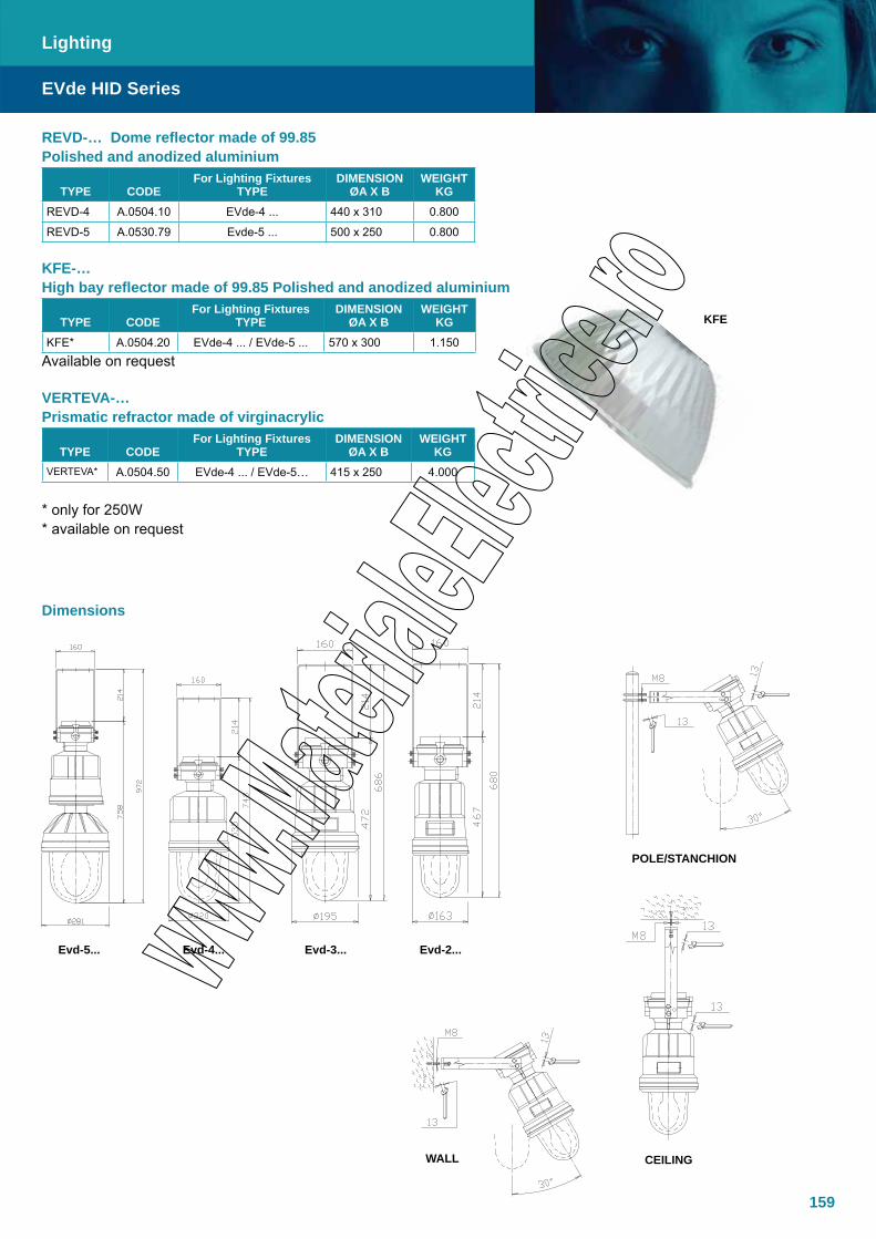
159
REVD-… Dome reflector made of 99.85 Polished and anodized aluminium
TYPE CODEFor Lighting Fixtures
TYPEDIMENSION
ØA X BWEIGHT
KGREVD-4 A.0504.10 EVde-4 ... 440 x 310 0.800
REVD-5 A.0530.79 Evde-5 ... 500 x 250 0.800 KFE-… High bay reflector made of 99.85 Polished and anodized aluminium
TYPE CODEFor Lighting Fixtures
TYPEDIMENSION
ØA X BWEIGHT
KGKFE* A.0504.20 EVde-4 ... / EVde-5 ... 570 x 300 1.150
Available on request
VERTEVA-…Prismatic refractor made of virginacrylic
TYPE CODEFor Lighting Fixtures
TYPEDIMENSION
ØA X BWEIGHT
KGVERTEVA* A.0504.50 EVde-4 ... / EVde-5… 415 x 250 4.000
* only for 250W * available on request
EVde HID Series
Lighting
Dimensions
Evd-5... Evd-4... Evd-3... Evd-2...
CEILINGWALL
POLE/STANCHION
KFE
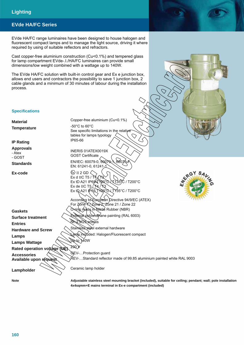
160
Specifications
Material Copper-free aluminium (Cu<0.1%)
Temperature -50°C to 60°CSee specific limitations in the relative tables for lamps typology
IP Rating IP65-66
Approvals- Atex- GOST
INERIS 01ATEX0019XGOST Certificate
Standards EN/IEC: 60079-0, 60079-1, 60079-7 EN: 61241-0, 61241-1
Ex-code II 2 GDEx d IIC T5 / T4 / T3 Ex tD A21 IP65 T100°C / T135°C / T200°CEx de IIC T5 / T4 / T3Ex tD A21 IP65 T100°C / T135°C / T200°C
According to European Directive 94/9/EC (ATEX)For Zone 1 / Zone 2, Zone 21 / Zone 22
Gaskets O-ring made in Nitrile Rubber (NBR)
Surface treatment External polyurethane painting (RAL 6003)
Entries Nr. 2 M25 entries
Hardware and Screw Stainless steel external hardware
Lamps Lamp included: Halogen/Fluorescent compact
Lamps Wattage Up to 140W
Rated operation voltage (UE) 230 V
AccessoriesAvailable upon request
GEV-…Protection guardREV-…Standard reflector made of 99.85 aluminium painted white RAL 9003
Lampholder Ceramic lamp holder
Note Adjustable stainless steel mounting bracket (included), suitable for ceiling; pendant; wall; pole installation4x4sqmm+E mains terminal in Ex-e compartment (included)
EVde HA/FC Series
Lighting
EVde HA/FC range luminaires have been designed to house halogen and fluorescent compact lamps and to manage the light source, driving it where required by using of suitable reflectors and refractors.
Cast copper-free aluminium construction (Cu<0.1%) and tempered glass for lamp compartment EVde-.I./HA/FC luminaires can provide small dimensions/low weight combined with a wattage up to 140W.
The EVde HA/FC solution with built-in control gear and Ex e junction box, allows end users and contractors the possibility to save 1 junction box, 2 cable glands and a minimum of 30 minutes of labour during the installation process.
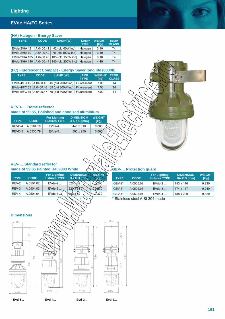
161
(HA) Halogen - Energy Saver TYPE CODE LAMP [W] LAMP
TYPEWEIGHT
[kg]TEMP. CLASS
EVde-2/HA 42 A.0400.41 42 (old 60W inc) Halogen 3.10 T4EVde-2/HA 70 A.0400.42 70 (old 100W inc) Halogen 3.10 T4EVde-2/HA 105 A.0400.43 105 (old 150W inc) Halogen 3.10 T4EVde-3/HA 140 A.0400.44 140 (old 200W inc) Halogen 4.40 T4
(FC) Fluorescent Compact - Energy Saver long life (8000h) TYPE CODE LAMP [W] LAMP
TYPEWEIGHT
[kg]TEMP. CLASS
EVde-4/FC 45 A.0400.45 45 (old 200W inc) Fluorescent 7.00 T4EVde-4/FC 65 A.0400.46 65 (old 300W inc) Fluorescent 7.00 T4EVde-5/FC 75 A.0400.47 75 (old 400W inc) Fluorescent 7.00 T4
REV-… Standard reflector made of 99.85 Painted Ral 9003 White
TYPE CODEFor Lighting
Fixtures TYPEDIMENSIONØA X B [mm]
WEIGHT [kg]
REV-2 A.0504.02 EVde-2 ... 320 x 89 0.270
REV-3 A.0504.03 EVde-3 ... 320 x 89 0.270
REV-4 A.0504.04 EVde-4 ... 400 x 89 0.370
EVde HA/FC Series
Lighting
GEV-… Protection guard
TYPE CODEFor Lighting
Fixtures TYPEDIMENSIONØA X B [mm]
WEIGHT [kg]
GEV-2* A.0505.02 EVde-2 ... 153 x 140 0.230
GEV-3* A.0505.03 EVde-3 ... 174 x 147 0.240
GEV-4* A.0505.04 EVde-4 ... 188 x 200 0.320* Stainless steel AISI 304 made
Dimensions
REVD-… Dome reflector made of 99.85, Polished and anodized aluminium
TYPE CODEFor Lighting
Fixtures TYPEDIMENSION
Ø A X B [mm]WEIGHT
[kg]REVD-4 A.0504.10 EVde-4... 440 x 310 0.800
REVD-5 A.0530.79 EVde-5... 500 x 250 0.800
Evd-5... Evd-4... Evd-3... Evd-2...

162
The TNXCX Ex d IIC low profile Xenon helideck floodlights are manu-factured in AISI316 stainless steel and are developed to withstand harsh offshore environments while providing safe, powerful illumination with no glare (e.g. to pilots or crew). High quality internal electronics provide a reliable and long-life light source to minimize maintenance.
SpecificationsMaterial Acid resistant stainless steel AISI 316LIP Rating IP66 (IP67/68 upon request)Ambient temperature -50ºC to +50ºCApprovals - Atex DNV-2004-OSL-ATEX-27278Standards EN/IEC: 60079-0, 60079-1, 60079-7 EN50281-1-1 CAP437Ex-code Ex d/Ex de IIC/IIB, II 2 G / D, T4 Suitable for Zone 1 and 2 Entries Ex e glands M25 or M20, or blanking plugs Gland Size Ex e M25 / M20 / BlankedLamp Xenon D25 / 35 WattOperating voltage 230, 120 VAC/12, 24 VDCPower consumption 50 WattWeight Approx. 10 kg.Lens Glass
TNXCX
Lighting
X ¤ X # # X - - #
254 = 254VAC230 = 220/240VAC 120 = 110/120VAC24 = 24VDC12 = 12VDC
E = Explosion Proof, I = Industrial
For XCX130:1 = Ex de with TNCN and 2xØ252 = Ex de c/w EEx e bottom 5xØ25 entries3 = Ex d with 1xM25 bottom entry4 = Ex d with 1xM25 bottom entry and flying lead (5m)
Diameter 130 = 130 mm
X = Xenon light source
Material types: C = SS316L, A = Aluminium
TNX
Typical floodlight with connection box or flying lead: XCX1301E-230 XCX1304E-12 TNXCX130 Ex de floodlight SS316L TNXCX130 Ex d floodlight SS316L TNCN connection box and cable bushing Flying lead cable (5m) 2 nos Ex e M25 entries One Ex d M25 entry DxL = 130x423 mm., 230VAC DxL = 130x378mm., 12VDC
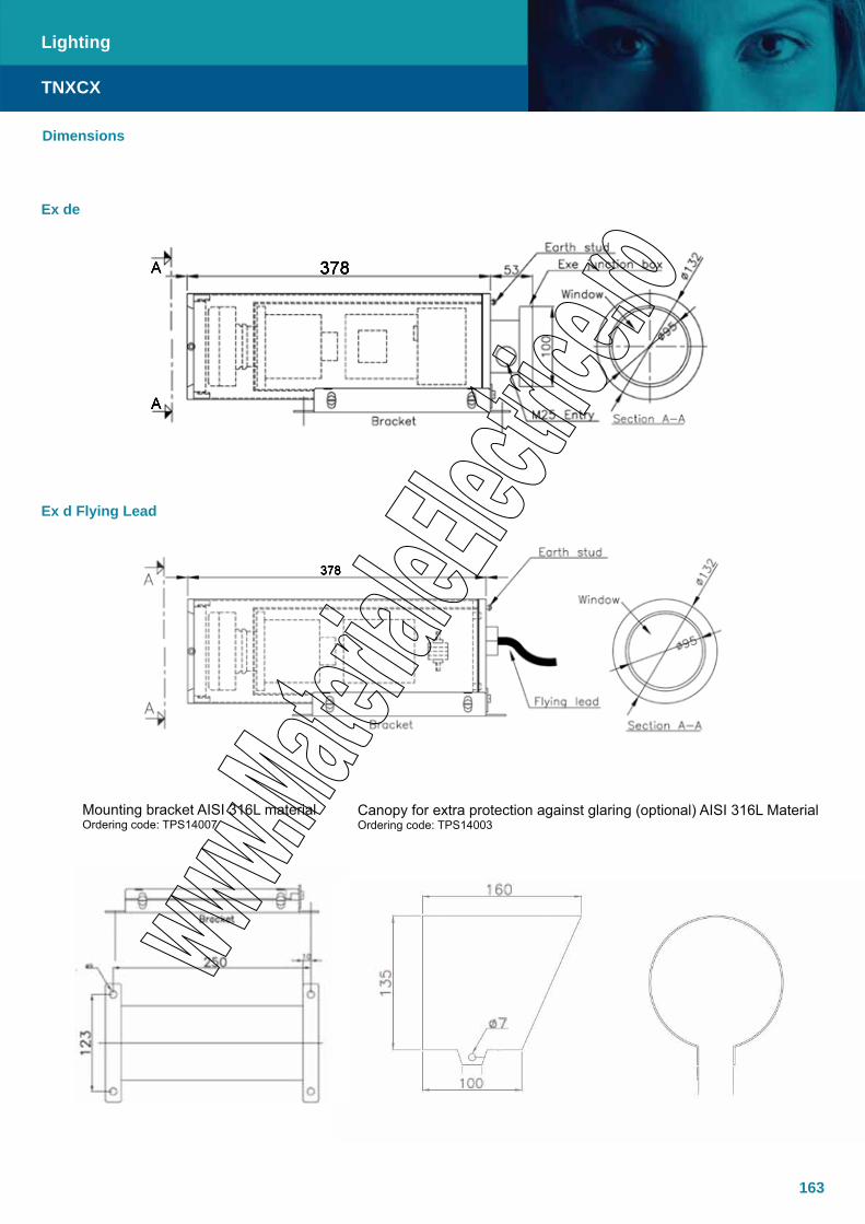
163
TNXCX
Lighting
Dimensions
Ex de
Ex d Flying Lead
Mounting bracket AISI 316L materialOrdering code: TPS14007
Canopy for extra protection against glaring (optional) AISI 316L MaterialOrdering code: TPS14003

164
Specifications
Material Copper-free aluminium (Cu<0.1%)Stainless steel AISI 316L
IP Rating IP65-66 Temperature -50°C to 55°CApprovals- Atex- GOST
INERIS 00ATEX0023X GOST Certificate
Standards EN/IEC: 60079-0, 60079-1, 60079-7 EN: 61241-0, 61241-1
Ex-code II 2 GDEx de IIB T3Ex de IIB+H2 T3 (upon request)Ex tD A21 IP65 T200°C
According to European Directive 94/9/EC (ATEX)For Zone 1/Zone 2, Zone 21/Zone 22
Gaskets Nitrile rubber gasket on flat jointSurface treatment External polyurethane painting (RAL 6003)Thread No. 2 M25 entries: one plugged off and one completed with a single seal cable gland our type
PNA 2, brass nichel plated.Hardware and Screw Captive stainless steel screws and stailess steel adjustable bracketLamps Halogen and discharge lampsLamps Wattage 150, 250, 400, 500, 2x70Ballast Low losses integral ballastRated operation voltage (UE) 230 VFrequency 50 HzPower factor > 0.9Lampholder Ceramic lampholder E-40 with antiloosening terminalsReflector Internal reflector, symmetrical distribution with narrow beam pure polished aluminium, fixed to
body by a safe wire even when removed during maintenance.AccessoriesAvailable upon request
Off -shore version with surface treatment for oil platforms and corrosive environmentsExternal colour ON REQUEST choice between Ral classificationHammered reflector for wide beamTop-pole mounting kit (pole size 2”) Voltages and frequencies ON REQUEST: - 240V 50 o 60 Hz - 254V 60 Hz - 120V 60 Hz - 127V 50 o 60 Hz - 208V 60 Hz
Specified Version forSpecial services
Floodlight with wind-up stand Italgas specified cod. Aplog/log-gestilog: GAS-d3Floodlight world wide Shell Oil specified M.e.s.c. no. 69.56.23.520.1 to 69.56.23.544.1 details with lamps in Shell standardization N.A.T.O. standarization floodlight specified for military purposes code NSN 5795-17-109-2235. Floodlight for lighting the escape platform/ship area “Life boat” FL-2x70-HA series with 2 halogen lamps 50 or 70W each with back refl ector for narrow beam , suitable for connection to emergency circuit powered by batteries always available on escape platform circuits. The narrow beam issued is lighting the sea surface below the safe boat to aid the life boat splash-down and as sign “ life boat “ for “ man in water
Note Hinged window on coverConnection to electric network via the backside through the Ex-e connection box with 4 terminals (4 sqmm.) bridged 2 by 2
FL Series
Lighting
The FL range of Ex de IIB / IIB+H2 of floodlights is manufactured in copper free aluminium and designed for halogen and discharge lamps up to 400/500W. The luminaire is available with offshore suitable RAL 6003 paint finish and internal anti-condensation coating. For ease of installation and maintenance the luminaire features an integral Ex e connection box and AISI304 stainless steel female threads for fastening bolts to minimize wear. The FL range luminaires are completed with lamp, ballast, HPF capacitor and igniter.

165
FL Series
Lighting
FloodlightCODE TYPE LAMPS TYPE POWER
[W]VOLTAGE
[V]WEIGHT
[kg]A.0421.14 FL 15 SA High Pressure Sodium 150 220/230 [50Hz] 24.7A.0421.15 FL 25 SA High Pressure Sodium 250 220/230 [50Hz] 25.8A.0421.19 FL 40 SA High Pressure Sodium 400 220/230 [50Hz] 27.0A.0421.20 FL 25 IM Metal Halide 250 220/230 [50Hz] 25.8A.0421.25 FL 40 IM Metal Halide 400 220/230 [50Hz] 24.8A.0421.30 FL 25 HG Mercury Vapours 250 220/230 [50Hz] 25.7A.0421.35 FL 40 HG Mercury Vapours 400 220/230 [50Hz] 22.9A.0421.40 FL 50 HA Halogen 500 220 21.0A.0421.45 FL 14 HA Halogen 2x70 48 22.0
FL…316 Floodlight
TYPE LAMPS TYPE POWER [W]
VOLTAGE [V]
WEIGHTPackage [kg]
FL 15 SA / 316 High Pressure Sodium 150 220/230 [50Hz] 50.2FL 25 SA / 316 High Pressure Sodium 250 220/230 [50Hz] 51.3FL 40 SA / 316 High Pressure Sodium 400 220/230 [50Hz] 52.5FL 25 IM / 316 Metal Halide 250 220/230 [50Hz] 51.3FL 40 IM / 316 Metal Halide 400 220/230 [50Hz] 50.3FL 25 HG / 316 Mercury Vapours 250 220/230 [50Hz] 51.2FL 40 HG / 316 Mercury Vapours 400 220/230 [50Hz] 47.5FL 50 HA / 316 Halogen 500 220 FL 14 SA / 316 Halogen 2x70 48
FL/AISI 316 Series… With the intent to answer to the off-shore market need of a totally corrosion proof apparatus able to withstand the combined action of salty marine and hydrocarbons environments, has been studied and developed the FL/AISI 316 Series. The high cost of ordinary and extraordinary maintenance on oil platforms fully justifies the replacement of Aluminum light alloy with Stainless steel 316.
The exclusive foundry know-how allowed Italsmea to cast and to machine units Aisi 316 made with L title and with same shape and thickens of Aluminum version also reducing to the lowest possible the weight.
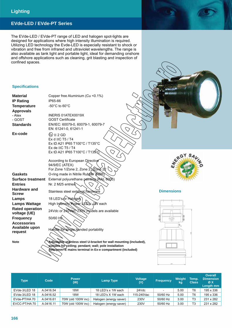
166
The EVde-LED / EVde-PT range of LED and halogen spot-lights are designed for applications where high intensity illumination is required. Utilizing LED technology the Evde-LED is especially resistant to shock or vibration and free from infrared and ultraviolet wavelengths. The range is also available as tank light and portable light, ideal for demanding onshore and offshore applications such as cleaning, grit blasting and inspection of confined spaces.
Type Code Power (W) Lamp Type Voltage
(V) Frequency Weight kg
Temp. Class
Overall Dimension
Ø X Length mm
EVde-3/LED 18 A.0416.54 18W 18 LED’s x 1W each 24Vdc - 5.00 T6 195 x 336EVde-3/LED 18 A.0416.52 18W 18 LED’s X 1W each 115-240Vac 50/60 Hz 5.00 T6 195 x 336EVde-PT/HA 70 A.0416.61 70W (old 100W inc) Halogen (energy saver) 230V 50/60 Hz 3.00 T3 231 x 282EVCC-PT/HA 70 A.0416.11 70W (old 100W inc) Halogen (energy saver) 230V 50/60 Hz 3.00 T3 231 x 282
Specifications
Material Copper free Aluminium (Cu <0.1%)IP Rating IP65-66Temperature -50°C to 60°CApprovals- Atex- GOST
INERIS 01ATEX0019XGOST Certificate
Standards EN/IEC: 60079-0, 60079-1, 60079-7EN: 61241-0, 61241-1
Ex-code II 2 GDEx d IIC T5 / T4 Ex tD A21 IP65 T100°C / T135°CEx de IIC T5 / T4Ex tD A21 IP65 T100°C / T135°C
According to European Directive 94/9/EC (ATEX)For Zone 1/Zone 2, Zone 21/Zone 22
Gaskets O-ring made in Nitrile Rubber (NBR)Surface treatment External polyurethane painting (RAL 6003)Entries Nr. 2 M25 entriesHardware and Screw Stainless steel external hardware
Lamps 18 LED’s or HalogenLamps Wattage High Intensity Power LED’s: 1W eachRated operation voltage (UE) 24Vdc or 240Vac. 230V models are available
Frequency 50/60 Hz.AccessoriesAvailable upon request Handle for single handed portability
Note Adjustable stainless steel U-bracket for wall mounting (included), suitable for ceiling; pendant; wall; pole installation4x4sqmm+E mains terminal in Ex-e compartment (included)
EVde-LED / EVde-PT Series
Lighting
Dimensions
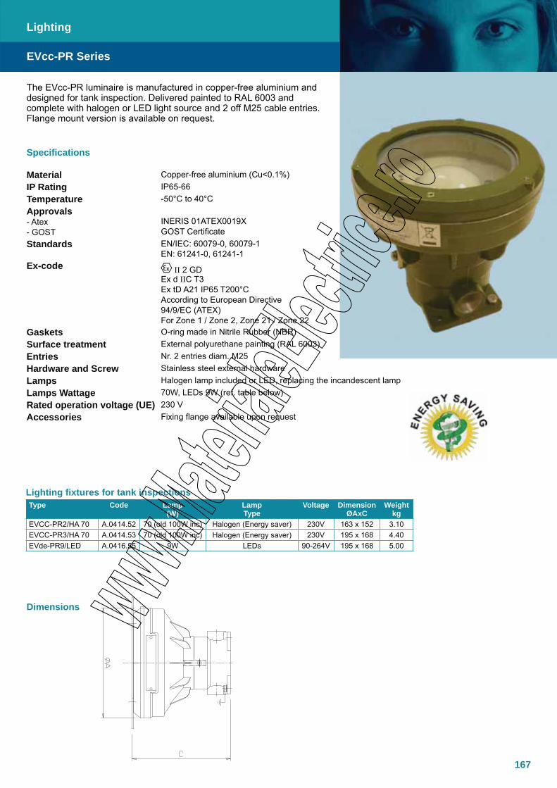
167
The EVcc-PR luminaire is manufactured in copper-free aluminium and designed for tank inspection. Delivered painted to RAL 6003 and complete with halogen or LED light source and 2 off M25 cable entries. Flange mount version is available on request.
Lighting fixtures for tank inspections Type Code Lamp
(W)LampType
Voltage DimensionØAxC
Weightkg
EVCC-PR2/HA 70 A.0414.52 70 (old 100W inc) Halogen (Energy saver) 230V 163 x 152 3.10EVCC-PR3/HA 70 A.0414.53 70 (old 100W inc) Halogen (Energy saver) 230V 195 x 168 4.40EVde-PR9/LED A.0416.55 9W LEDs 90-264V 195 x 168 5.00
Specifications
Material Copper-free aluminium (Cu<0.1%)IP Rating IP65-66Temperature -50°C to 40°CApprovals- Atex- GOST
INERIS 01ATEX0019XGOST Certificate
Standards EN/IEC: 60079-0, 60079-1EN: 61241-0, 61241-1
Ex-code II 2 GDEx d IIC T3 Ex tD A21 IP65 T200°CAccording to European Directive 94/9/EC (ATEX)For Zone 1 / Zone 2, Zone 21 / Zone 22
Gaskets O-ring made in Nitrile Rubber (NBR)Surface treatment External polyurethane painting (RAL 6003)Entries Nr. 2 entries diam. M25Hardware and Screw Stainless steel external hardwareLamps Halogen lamp included or LED, replacing the incandescent lampLamps Wattage 70W, LEDs 9W (ref. table below)Rated operation voltage (UE) 230 V Accessories Fixing flange available upon request
EVcc-PR Series
Lighting
Dimensions

168
Specifications
Material Copper-free aluminium (Cu<0.1%)IP Rating IP65-66Temperature -50°C to 60°CApprovals- Atex- GOST
INERIS 01ATEX0019XGOST Certificate
Standards EN/IEC: 60079-0, 60079-1 EN: 61241-0, 61241-1
Ex-code II 2 GDEx d IIC T4 / T3 Ex tD A21 IP65 T135°C / T200°CAccording to European Directive 94/9/EC (ATEX)For Zone 1/Zone 2, Zone 21/Zone 22
Gaskets O-ring made in Nitrile Rubber (NBR)Surface treatment External polyurethane painting (RAL 6003)Entries Nr. 1 entry with cable gland PAT2Hardware and Screw Stainless steel external hardwareLamps Halogen lamp includedLamps Wattage 42 or 70 wattRated operation voltage (UE) 230 V Accessories transformer 240/24V 100VA available upon request
The EVA luminaire is manufactured in copper free aluminium and designed for use as a hand-lamp, complete with handle made of insulating material, protection guard and halogen lamp.
HAND LAMP for halogen Lamp (replacing the incandescent lamp)
Type CodeLamp
WLamp Type
VoltageV
Weightkg
EVA-2/HA 42 (EVP 60) A.0413.12 42 (old 60W inc) Halogen (energy saver) 230V 3.10EVA-2/HA 70 (EVP 100) A.0413.13 70 (old 100W inc) Halogen (energy saver) 230V 4.40
EVA Series
Lighting
Dimensions
Hand –lamp for halogen lamps with transformer 240/24V 100VA

169
The TNCLS range of Ex em LED backlights are designed for use to illuminate level gauges in all kinds of industry where an explosive atmosphere may be present. TNCLS offers a long life, low maintenance LED solution to enable the operator to accurately read the level through the gauge glass.
SpecificationsMaterial Acid resistant stainless steel AISI 316LIP Rating IP66Temperature -20ºC to + 45ºC (T4)Approvals - Atex DNV-2002-OSL-ATEX-0195Standards EN/IEC: 60079-0, 60079-7, 60079-18Ex-Code Ex em II T4 II 2 GSurface treatment AcidizedEarthing M6 inside and outsideCable entry Max. 2xM25 in top and / or bottom, and/or sidesPower comsumption Approx. 3VA per moduleVoltage 220-240VAC or 254VACFrequency 50-60 HzHumidity 100%Terminals Minimum 4x2.5 m²Lumination colour Yellow
TNCLS
Lighting
Size-qty. modules
Total length (A) mm
Light exposure (B) mm
Weight kg
27-1 270 250 2.330-1 300 280 2.534-1 340 320 2.736-1 360 340 2.827-2 540 520 4.330-2 600 580 4.634-2 680 660 5.136-2 720 700 5.327-3 810 790 6.230-3 900 880 6.734-3 1020 1000 7.336-3 1080 1060 7.530-4 1200 1180 8.5
Several units can be assembles to one columnType key: TNCLS L-X
L = Module lendthX = No. of modules
Total length: A = L*XOther sizes upon request
Size-qty. modules
Total length (A) mm
Light exposure (B) mm
Weight kg
27-1 270 250 2.330-1 300 280 2.534-1 340 320 2.736-1 360 340 2.827-2 540 520 4.330-2 600 580 4.634-2 680 660 5.136-2 720 700 5.327-3 810 790 6.230-3 900 880 6.734-3 1020 1000 7.336-3 1080 1060 7.530-4 1200 1180 8.5
Dimensions
181
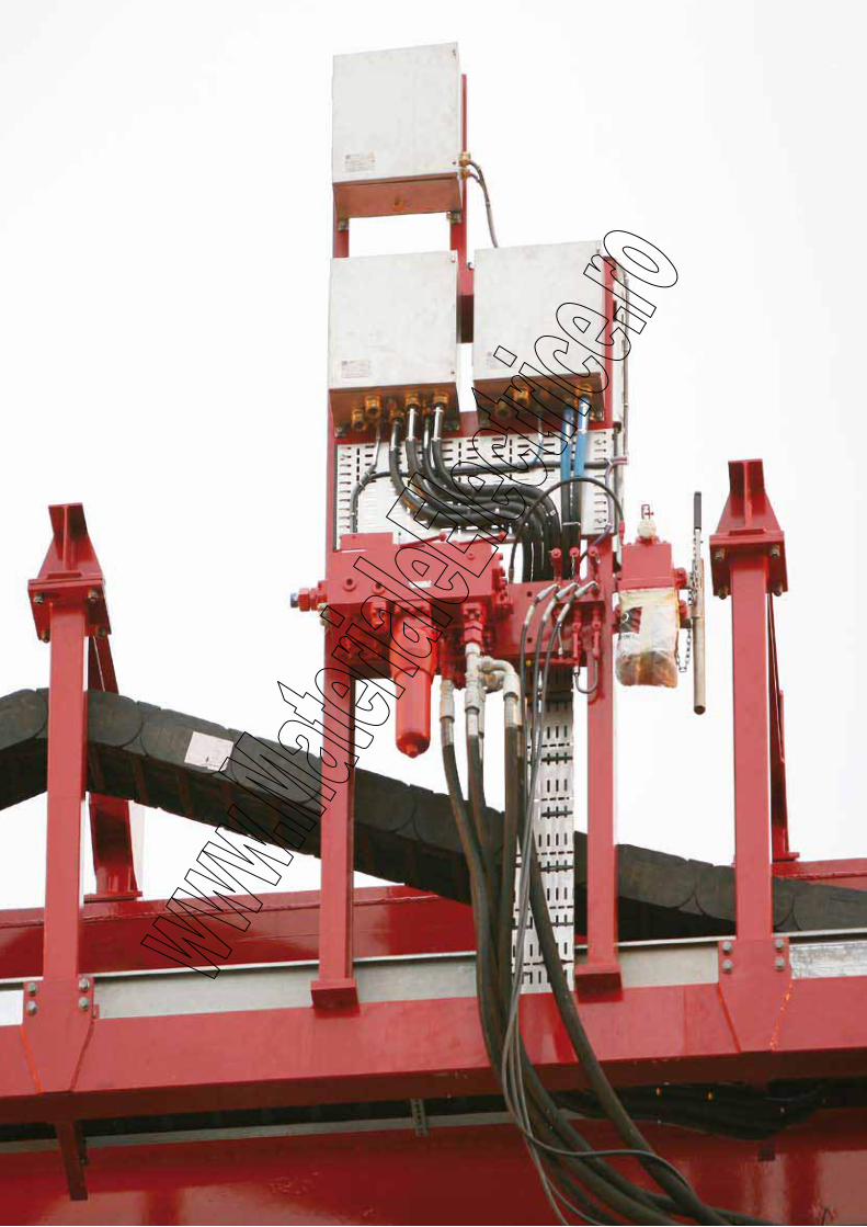
170
171
Cable Glands and Accessories
PAP SeriesDouble seal, armoured cable, Ex d/e, Brass / AISI 316L
PNA SeriesSingle seal, armoured cable, Ex d/e, Brass / AISI 316L
PSF SeriesSingle seal, armoured cable, Male-Female, Ex d/e, Brass / AISI 316L
PSM SeriesSingle seal, armoured cable, Male-Male, Ex d/e, Brass / AISI 316L
PBD SeriesDouble seal, lead sheath unarmoured cable, Ex d/e, Brass / AISI 316L
PBS SeriesSingle seal, lead sheath unarmoured cable, Ex d/e, Brass / AISI 316L
PDB SeriesDouble seal, lead sheath armoured cable, Ex d/e, Brass / AISI 316L
PSB SeriesSingle seal, lead sheath armoured cable, Ex d/e, Brass / AISI 316L
PBAX SeriesSingle seal barrier type, armoured cable, Ex d/e, Brass / AISI 316L
PND SeriesDouble seal, unarmoured cable, Ex d/e, Brass / AISI 316L
PABAX SeriesDouble seal barrier type, armoured cable, Ex d/e, Brass / AISI 316L
PMS SeriesSingle seal barrier type, unarmoured cable, Ex d/e, Brass / AISI 316L
PMD SeriesDouble seal barrier type, unarmoured cable, Ex d/e, Brass / AISI 316L
PNS SeriesSingle seal, unarmoured cable, Ex d/e, Brass / AISI 316L
Fitting Accessories
176178180182184186188190192194196198200202205
TRCG SeriesPolyamid Ex e/i cable gland
TRCG SeriesPolyamid Ex e plugs
TRCG SeriesNickel-plated brass, Ex e cable glands
172173174

172
Polyamid cable gland with metric threads for use in Ex e enclosure,with high IP rating.
TRCG
Cable Glands and Accessories
Specifications
Material PolyamidIP Rating IP68Temperature -35°C to +95°C Approvals- Atex LCIE 07ATEX6082XStandards EN/IEC: 60079-0, 60079-7
EN: 61241-0, 61241-1Ex-code Ex e Gaskets IncludedThread Metric, pitch 1.5Version on Request
Other threads PG/NPTLight blue colour for use in Ex i circuits
Accessories Lock nut
Drawing
H = SW = Key size
Threads Clamping range
H (mm)
E (mm)
L (mm)
ReferencePacking
Accessories
Lock nutsEx e (black) Ex i (blue)M16 5.0 - 8.0 19 10 37 TRCG12M16099 TRCG12M16095 50 TRCG32M16000
M16 5.0 - 10.0 22 10 39 TRCG12M16119 TRCG12M16115 50 TRCG32M16000
M20 7.0 - 12.0 24 10 40 TRCG12M20139 TRCG12M20135 50 TRCG32M20000
M20 10.0 - 14.0 27 10 43 TRCG12M20169 TRCG12M20165 50 TRCG32M20000
M25 10.0 - 14.0 27 10 45 TRCG12M25169 TRCG12M25165 50 TRCG32M25000
M25 12.0 - 18.0 33 10 49 TRCG12M25219 TRCG12M25215 20 TRCG32M25000
M32 16.0 - 25.0 42 10 52 TRCG12M32009 TRCG12M32005 20 TRCG32M32000
M40 22.0 - 32.0 53 10 62 TRCG12M40009 TRCG12M40005 10 TRCG32M40009
M50 28.0 - 38.5 60 12 67 TRCG12M50009 TRCG12M50005 5 TRCG32M50009
M63 40.0 - 48.0 70 12 68 TRCG12M63009 TRCG12M63005 5 TRCG32M63009
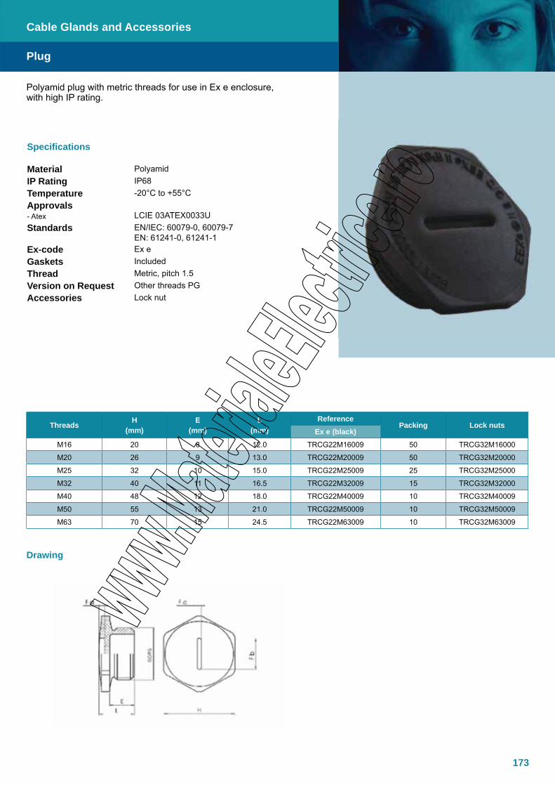
173
Plug
Cable Glands and Accessories
Specifications
Material PolyamidIP Rating IP68Temperature -20°C to +55°C Approvals- Atex LCIE 03ATEX0033UStandards EN/IEC: 60079-0, 60079-7
EN: 61241-0, 61241-1Ex-code Ex eGaskets IncludedThread Metric, pitch 1.5Version on Request Other threads PGAccessories Lock nut
Drawing
Polyamid plug with metric threads for use in Ex e enclosure,with high IP rating.
Threads H (mm)
E (mm)
L (mm)
ReferencePacking Lock nuts
Ex e (black)M16 20 8 12.0 TRCG22M16009 50 TRCG32M16000
M20 26 9 13.0 TRCG22M20009 50 TRCG32M20000
M25 32 10 15.0 TRCG22M25009 25 TRCG32M25000
M32 40 11 16.5 TRCG22M32009 15 TRCG32M32000
M40 48 12 18.0 TRCG22M40009 10 TRCG32M40009
M50 55 13 21.0 TRCG22M50009 10 TRCG32M50009
M63 70 15 24.5 TRCG22M63009 10 TRCG32M63009
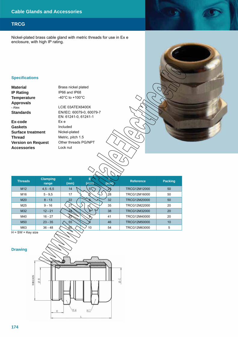
174
TRCG
Cable Glands and Accessories
Specifications
Material Brass nickel platedIP Rating IP66 and IP68Temperature -40°C to +100°CApprovals- Atex LCIE 03ATEX6400XStandards EN/IEC: 60079-0, 60079-7
EN: 61241-0, 61241-1Ex-code Ex eGaskets IncludedSurface treatment Nickel-platedThread Metric, pitch 1.5Version on Request Other threads PG/NPTAccessories Lock nut
Drawing
Nickel-plated brass cable gland with metric threads for use in Ex e enclosure, with high IP rating.
H = SW = Key size
Threads Clamping range
H(mm)
E (mm)
L (mm) Reference Packing
M12 4,5 - 6,5 14 5 25 TRCG12M12000 50
M16 5 - 9,5 17 5 28 TRCG12M16000 50
M20 8 - 13 22 6 32 TRCG12M20000 50
M25 9 - 16 27 7 35 TRCG12M22000 20
M32 12 - 21 34 8 38 TRCG12M32000 20
M40 16 - 27 42 8 41 TRCG12M40000 20
M50 23 - 35 55 9 46 TRCG12M50000 10
M63 36 - 48 65 10 54 TRCG12M63000 5

175

176
Double seal cable glands suitable for armoured cables. Nickel-chrome plated brass, hexagon shape, anti-ageing EPDM oil resistant gaskets.
PAP-… Series cable glands are used in classified area Zone 1 & 2 and Zone 21 & 22.
PAP
Cable Glands and Accessories
Specifications
Material Brass (alternative AISI316L, aluminium)IP Rating IP66Temperature -50°C to 110°CApprovals- Atex
- GOST
INERIS 02ATEX0084TüV: AEX-11632-XGOST Certificate
Standards EN/IEC: 60079-0, 60079-1, 60079-7EN: 61241-0, 61241-1
Ex-code II 2 GD or I M2Ex d IIC / Ex e II / Ex d IEx tD A21 IP66According to European Directive 94/9/EC (ATEX)For Zone 1 / Zone 2, Zone 21 / Zone 22
Gaskets EPDMSurface treatment Nickel-chrome PlatedThread ANSI B1.20.1 NPT (normally in stock): type number will assume the ending NPT
Metric pitch 1.5UNI 6125
Version on Request
Cable glands made of Stainless Steel AISI 304: type number will assume the ending 304. Example PAP-1-A1/304Cable glands made of Stainless steel AISI 316L: type number will assume the ending 316. Example PAP-1-A1/316Cable glands Aluminium Anticorodal made (not suitable for Group I): The type number will assume the ending Al. Example PAP-1-A1/Al
Accessories Rubber Shroud for cable glands protection
Note All cable glands of a.m. series will be supplied with armouring-ring and cone nickel-chrome plated brass made (if not differently in offer or in order acknowledgement)
Note The cable glands for armoured cables are suitable for armour thickness up to 1.25mm. Armours thicker than 1.26mm is available upon request

177
PAP
Cable Glands and Accessories
Dimensions
TypeCable under
armour(inner seal)
Cable overall
diameter(outer seal)
ØMaximum o.d.
THREAD TYPEExternal
cable Metric Pitch UNI 6125 NPTF A B C D E Size Code Size Code Size Code
PAP-1/A1B1 6-9 8-11 18 85 65 20 33 30 M20 A.1800.18 Uni 6125 ½” A.1801.01 NPT ½” A.1801.51
PAP-1/A1B2 6-9 11-14 18 85 65 20 33 30 M20 A.1800.19 Uni 6125 ½” A.1801.02 NPT ½” A.1801.52
PAP-1/A2B3 9-12 14-17 18 85 65 20 33 30 M20 A.1800.21 Uni 6125 ½” A.1801.03 NPT ½” A.1801.53
PAP-2/A1B1 6-9 14-17 24 85 65 20 33 36 M25 A.1800.23 Uni 6125 ¾” A.1802.01 NPT ¾” A.1802.51
PAP-2/A2B1 9-12 14-17 24 85 65 20 33 36 M25 A.1800.24 Uni 6125 ¾” A.1802.02 NPT ¾” A.1802.52
PAP-2/A3B2 11-14 17-20 24 85 65 20 33 36 M25 A.1800.27 Uni 6125 ¾” A.1802.03 NPT ¾” A.1802.53
PAP-2/A4B3 14-17 20-23 24 85 65 20 33 36 M25 A.1800.28 Uni 6125 ¾” A.1802.04 NPT ¾” A.1802.54
PAP-3/A1B1 14-17 20-23 30 93 68 25 49 44 M32 A.1803.21 Uni 6125 1” A.1803.01 NPT 1” A.1803.51
PAP-3/A2B2 17-20 23-26 30 93 68 25 49 44 M32 A.1803.22 Uni 6125 1” A.1803.02 NPT 1” A.1803.52
PAP-3/A3B3 20-23 26-29 30 93 68 25 49 44 M32 A.1803.23 Uni 6125 1” A.1803.03 NPT 1” A.1803.53
PAP-5/A2B2 23-26 29-32 43 93 68 25 62 56 M50 A.1805.22 Uni 6125 1 1/2” A.1805.02 NPT 1 1/2” A.1805.52
PAP-5/A3B3 26-29 32-36 43 93 68 25 62 56 M50 A.1805.23 Uni 6125 1 1/2” A.1805.03 NPT 1 1/2” A.1805.53
PAP-5/A4B4 29-32 36-39 43 93 68 25 62 56 M50 A.1805.24 Uni 6125 1 1/2” A.1805.04 NPT 1 1/2” A.1805.54
PAP-5/A5B5 32-36 39-42 43 93 68 25 62 56 M50 A.1805.25 Uni 6125 1 1/2” A.1805.05 NPT 1 1/2” A.1805.55
PAP-6/A2B2 36-39 44-48 57 95 71 25 78 70 M63 A.1806.22 Uni 6125 2” A.1806.02 NPT 2” A.1806.52
PAP-6/A3B3 39-42 48-52 57 95 71 25 78 70 M63 A.1806.23 Uni 6125 2” A.1806.03 NPT 2” A.1806.53
PAP-6/A4B4 42-46 52-56 57 95 71 25 78 70 M63 A.1806.24 Uni 6125 2” A.1806.04 NPT 2” A.1806.54
PAP-7/A2B2 44-48 55-59 69 100 71 32 92 83 M75 A.1807.22 Uni 6125 2 1/2” A.1807.02 NPT 2 1/2” A.1807.52
PAP-7/A3B3 48-52 59-63 69 100 71 32 92 83 M75 A.1807.23 Uni 6125 2 1/2” A.1807.03 NPT 2 1/2” A.1807.53
PAP-7/A4B4 52-56 63-67 69 100 71 32 92 83 M75 A.1807.24 Uni 6125 2 1/2” A.1807.04 NPT 2 1/2” A.1807.54
PAP-7/A5B4 56-60 63-67 69 100 71 32 92 83 M75 A.1807.25 Uni 6125 2 1/2” A.1807.05 NPT 2 1/2” A.1807.55
PAP-8/A4B4 56-60 63-67 79 100 71 32 103 93 M80 A.1808.24 Uni 6125 3” A.1808.04 NPT 3” A.1808.54
PAP-8/A5B5 59-63 67-69 79 100 71 32 103 93 M80 A.1808.25 Uni 6125 3” A.1808.05 NPT 3” A.1808.55
PAP-8/A6B6 63-67 69-73 79 100 71 32 103 93 M80 A.1808.26 Uni 6125 3” A.1808.06 NPT 3” A.1808.56
PAP-8/A7B7 67-71 73-11 79 100 71 32 103 93 M80 A.1808.27 Uni 6125 3” A.1808.07 NPT 3” A.1808.57

178
Single seal cable glands suitable for armoured cables. Nickel-chrome plated brass, hexagon shape, anti-ageing EPDM oil resistant gaskets.
PNA-… Series cable glands are used in classified area Zone 1 & 2 and Zone 21 & 22.
PNA
Cable Glands and Accessories
Specifications
Material BrassIP Rating IP66Temperature -50°C to 110°CApprovals- Atex- GOST
INERIS 02ATEX0084GOST Certificate
Standards EN/IEC: 60079-0, 60079-1, 60079-7EN: 61241-0, 61241-1
Ex-code II 2 GD or I M2Ex d IIC / Ex e II / Ex d IEx tD A21 IP66According to European Directive 94/9/EC (ATEX)For Zone 1 / Zone 2, Zone 21 / Zone 22
Gaskets EPDMSurface treatment Nickel-chrome Plated
Thread ANSI B1.20.1 NPT (normally in stock): type number will assume the ending NPTMetric pitch 1.5UNI 6125
Version on Request Cable glands made of Stainless steel AISI 304: type number will assume the ending 304. Example PNA-1-A1/304Cable glands made of Steinless steel AISI 316L: type number will assume the ending 316. Example PNA-1-A1/316Cable glands Aluminium Anticorodal made (not suitable for Group I): The type number will assume the ending Al. Example PNA-1-A1/Al
Accessories Rubber Shroud for cable glands protection
Note All cable glands of a.m. series will be supplied with armouring-ring and cone nickel-chrome plated brass made (if not differently specified in offer or in order acknowledgment)
Note The cable glands for armoured cables are suitable for armour thickness up to 1.25mm. Armours thicker than 1.26mm is available upon request
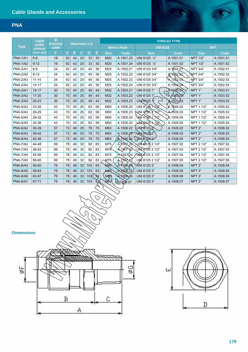
179
PNA
Cable Glands and Accessories
Dimensions
TypeCable under
armour (inner seal)
ØExternal
cableMaximum o.d.
THREAD TYPE
Metric Pitch UNI 6125 NPTF A B C D E Size Code Size Code Size Code
PNA-1/A1 6-9 18 62 42 20 33 30 M20 A.1501.23 UNI 6125 ½” A.1501.01 NPT 1/2” A.1501.51
PNA-1/A2 9-12 18 62 42 20 33 30 M20 A.1501.24 UNI 6125 ½” A.1501.02 NPT 1/2” A.1501.52PNA-2/A1 6-9 24 62 42 20 40 36 M25 A.1502.21 UNI 6125 3/4” A.1502.01 NPT 3/4” A.1502.51PNA-2/A2 9-12 24 62 42 20 40 36 M25 A.1502.22 UNI 6125 3/4” A.1502.02 NPT 3/4” A.1502.52PNA-2/A3 11-14 24 62 42 20 40 36 M25 A.1502.23 UNI 6125 3/4” A.1502.03 NPT 3/4” A.1502.53PNA-2/A4 14-17 24 62 42 20 40 36 M25 A.1502.24 UNI 6125 3/4” A.1502.04 NPT 3/4” A.1502.54PNA-3/A1 14-17 30 70 45 25 49 44 M32 A.1503.21 UNI 6125 1” A.1503.01 NPT 1” A.1503.51PNA-3/A2 17-20 30 70 45 25 49 44 M32 A.1503.22 UNI 6125 1” A.1503.02 NPT 1” A.1503.52PNA-3/A3 20-23 30 70 45 25 49 44 M32 A.1503.23 UNI 6125 1” A.1503.03 NPT 1” A.1503.53
PNA-5/A2 23-26 43 70 45 25 62 56 M50 A.1505.22 UNI 6125 1 1/2” A.1505.02 NPT 1 1/2” A.1505.52PNA-5/A3 26-29 43 70 45 25 62 56 M50 A.1505.23 UNI 6125 1 1/2” A.1505.03 NPT 1 1/2” A.1505.53PNA-5/A4 29-32 43 70 45 25 62 56 M50 A.1505.24 UNI 6125 1 1/2” A.1505.04 NPT 1 1/2” A.1505.54PNA-5/A5 32-36 43 70 45 25 62 56 M50 A.1505.25 UNI 6125 1 1/2” A.1505.05 NPT 1 1/2” A.1505.55PNA-6/A2 36-39 57 72 46 25 78 70 M63 A.1506.22 UNI 6125 2” A.1506.02 NPT 2” A.1506.52PNA-6/A3 39-42 57 72 46 25 78 70 M63 A.1506.23 UNI 6125 2” A.1506.03 NPT 2” A.1506.53PNA-6/A4 42-46 57 72 46 25 78 70 M63 A.1506.24 UNI 6125 2” A.1506.04 NPT 2” A.1506.54PNA-7/A2 44-48 69 78 46 32 92 83 M75 A.1507.22 UNI 6125 2 1/2” A.1507.02 NPT 2 1/2” A.1507.52PNA-7/A3 48-52 69 78 46 32 92 83 M75 A.1507.23 UNI 6125 2 1/2” A.1507.03 NPT 2 1/2” A.1507.53PNA-7/A4 52-56 69 78 46 32 92 83 M75 A.1507.24 UNI 6125 2 1/2” A.1507.04 NPT 2 1/2” A.1507.54PNA-7/A5 56-60 69 78 46 32 92 83 M75 A.1507.25 UNI 6125 2 1/2” A.1507.05 NPT 2 1/2” A.1507.55PNA-8/A4 56-60 79 78 46 32 103 93 M80 A.1508.24 UNI 6125 3” A.1508.04 NPT 3” A.1508.54PNA-8/A5 59-63 79 78 46 32 103 93 M80 A.1508.25 UNI 6125 3” A.1508.05 NPT 3” A.1508.55PNA-8/A6 63-67 79 78 46 32 103 93 M80 A.1508.26 UNI 6125 3” A.1508.06 NPT 3” A.1508.56PNA-8/A7 67-71 79 78 46 32 103 93 M80 A.1508.27 UNI 6125 3” A.1508.07 NPT 3” A.1508.57
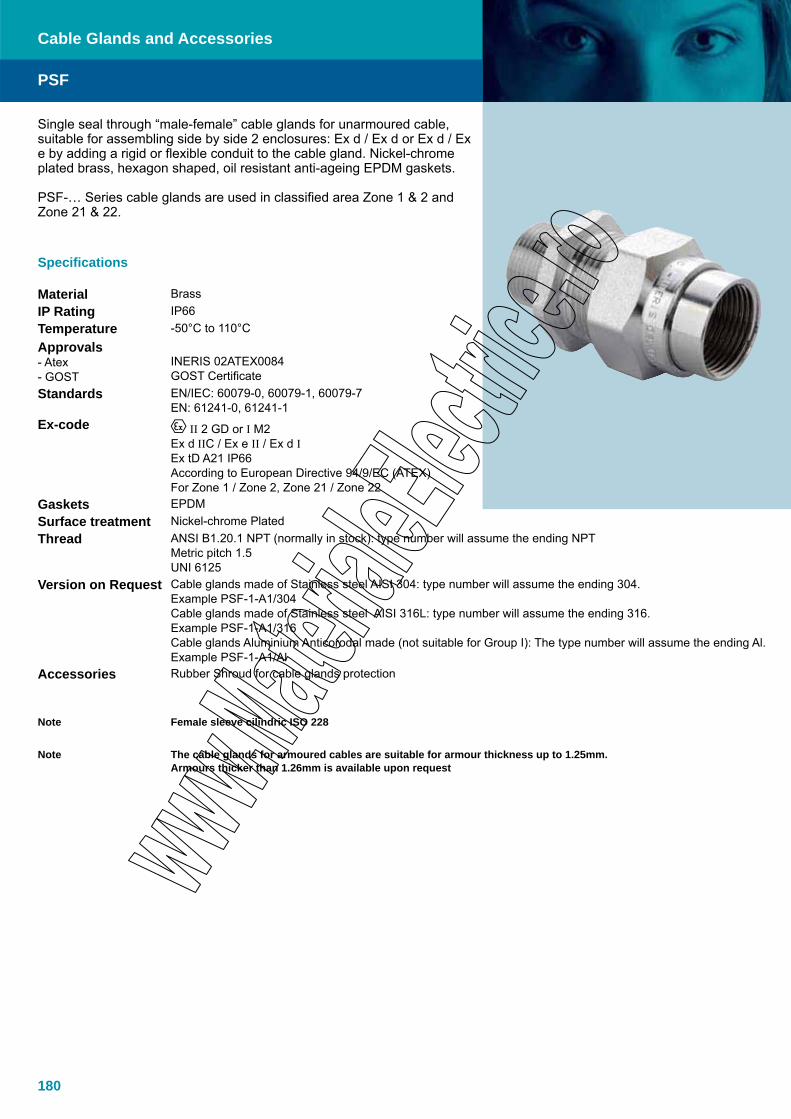
180
Single seal through “male-female” cable glands for unarmoured cable, suitable for assembling side by side 2 enclosures: Ex d / Ex d or Ex d / Ex e by adding a rigid or flexible conduit to the cable gland. Nickel-chrome plated brass, hexagon shaped, oil resistant anti-ageing EPDM gaskets.
PSF-… Series cable glands are used in classified area Zone 1 & 2 and Zone 21 & 22.
Specifications
Material BrassIP Rating IP66Temperature -50°C to 110°CApprovals- Atex- GOST
INERIS 02ATEX0084GOST Certificate
Standards EN/IEC: 60079-0, 60079-1, 60079-7EN: 61241-0, 61241-1
Ex-code II 2 GD or I M2Ex d IIC / Ex e II / Ex d IEx tD A21 IP66According to European Directive 94/9/EC (ATEX)For Zone 1 / Zone 2, Zone 21 / Zone 22
Gaskets EPDMSurface treatment Nickel-chrome PlatedThread ANSI B1.20.1 NPT (normally in stock): type number will assume the ending NPT
Metric pitch 1.5UNI 6125
Version on Request Cable glands made of Stainless steel AISI 304: type number will assume the ending 304. Example PSF-1-A1/304Cable glands made of Stainless steel AISI 316L: type number will assume the ending 316. Example PSF-1-A1/316Cable glands Aluminium Anticorodal made (not suitable for Group I): The type number will assume the ending Al. Example PSF-1-A1/Al
Accessories Rubber Shroud for cable glands protection
Note Female sleeve cilindric ISO 228
Note The cable glands for armoured cables are suitable for armour thickness up to 1.25mm. Armours thicker than 1.26mm is available upon request
PSF
Cable Glands and Accessories

181
PSF
Cable Glands and Accessories
TypeCable overall
diameter
Free conpling threading
Maximum o.d.THREAD TYPE
Metric Pitch UNI 6125 NPTA B C D E Size Code Size Code Size Code
PSF-1/A1 6-9 ½” 73 53 20 33 30 M20 A.2821.01 UNI 6125 ½” A.2801.01 NPT ½” A.2811.01
PSF-1/A2 9-12 ½” 73 53 20 33 30 M20 A.2821.02 UNI 6125 ½” A.2801.02 NPT ½” A.2811.02PSF-2/A1 6-9 ¾” 73 53 20 40 36 M25 A.2822.01 UNI 6125 3/4” A.2802.01 NPT 3/4” A.2812.01PSF-2/A2 9-12 ¾” 73 53 20 40 36 M25 A.2822.02 UNI 6125 3/4” A.2802.02 NPT 3/4” A.2812.02PSF-2/A3 11-14 ¾” 73 53 20 40 36 M25 A.2822.03 UNI 6125 3/4” A.2802.03 NPT 3/4” A.2812.03PSF-2/A4 14-17 ¾” 73 53 20 40 36 M25 A.2822.04 UNI 6125 3/4” A.2802.04 NPT 3/4” A.2812.04PSF-3/A1 14-17 1” 88 63 25 49 44 M32 A.2823.01 UNI 6125 1” A.2803.01 NPT 1” A.2813.01PSF-3/A2 17-20 1” 88 63 25 49 44 M32 A.2823.02 UNI 6125 1” A.2803.02 NPT 1” A.2813.02PSF-3/A3 20-23 1” 88 63 25 49 44 M32 A.2823.03 UNI 6125 1” A.2803.03 NPT 1” A.2813.03
PSF-5/A2 23-26 1 ½” 89 64 25 65 58 M50 A.2825.02 UNI 6125 1 1/2” A.2805.02 NPT 1 1/2” A.2815.02PSF-5/A3 26-29 1 ½” 89 64 25 65 58 M50 A.2825.03 UNI 6125 1 1/2” A.2805.03 NPT 1 1/2” A.2815.03PSF-5/A4 29-32 1 ½” 89 64 25 65 58 M50 A.2825.04 UNI 6125 1 1/2” A.2805.04 NPT 1 1/2” A.2815.04PSF-5/A5 32-36 1 ½” 89 64 25 65 58 M50 A.2825.05 UNI 6125 1 1/2” A.2805.05 NPT 1 1/2” A.2815.05PSF-6/A2 36-39 2”
On request
M63 A.2826.02 UNI 6125 2” A.2806.02 NPT 2” A.2816.02PSF-6/A3 39-42 2” M63 A.2826.03 UNI 6125 2” A.2806.03 NPT 2” A.2816.03PSF-6/A4 42-46 2” M63 A.2826.04 UNI 6125 2” A.2806.04 NPT 2” A.2816.04PSF-7/A2 44-48 2 ½”
On request
M75 A.2827.02 UNI 6125 2 1/2” A.2807.02 NPT 2 1/2” A.2817.02PSF-7/A3 48-52 2 ½” M75 A.2827.03 UNI 6125 2 1/2” A.2807.03 NPT 2 1/2” A.2817.03PSF-7/A4 52-56 2 ½” M75 A.2827.04 UNI 6125 2 1/2” A.2807.04 NPT 2 1/2” A.2817.04PSF-7/A5 56-60 2 ½” M75 A.2827.05 UNI 6125 2 1/2” A.2807.05 NPT 2 1/2” A.2817.05PSF-8/A4 56-60 3”
On request
M80 A.2828.04 UNI 6125 3” A.2808.04 NPT 3” A.2818.04PSF-8/A5 59-63 3” M80 A.2828.05 UNI 6125 3” A.2808.05 NPT 3” A.2818.05PSF-8/A6 63-67 3” M80 A.2828.06 UNI 6125 3” A.2808.06 NPT 3” A.2818.06PSF-8/A7 67-71 3” M80 A.2828.07 UNI 6125 3” A.2808.07 NPT 3” A.2818.07
Dimensions

182
Single seal through “male-male” cable glands for unaroumred cable, suit-able for assembling side by side 2 enclosures: Ex d/Ex d or Ex d/Ex e by adding a rigid or flexible conduit to the cable gland. Nickel-chrome plated brass, hexagon shaped, oil resistant anti-ageing EPDM gaskets.
PSM-… Series cable glands are used in classified area Zone 1 & 2 and Zone 21 & 22.
Specifications
Material BrassIP Rating IP66Temperature -50°C to 110°C
Approvals- Atex- GOST
INERIS 02ATEX0084GOST Certificate
Standards EN/IEC: 60079-0, 60079-1, 60079-7EN: 61241-0, 61241-1
Ex-code II 2 GD or I M2Ex d IIC / Ex e II / Ex d IEx tD A21 IP66According to European Directive 94/9/EC (ATEX)For Zone 1 / Zone 2, Zone 21 / Zone 22
Gaskets EPDMSurface treatment Nickel-chrome Plated
Thread ANSI B1.20.1 NPT (normally in stock): type number will assume the ending NPTMetric pitch 1.5UNI 6125
Version on Request Cable glands made of Stainless steel AISI 304: type number will assume the ending 304. Example PSM-1-A1/304Cable glands made of Stainless steel AISI 316L: type number will assume the ending 316.Example PSM-1-A1/316Cable glands Aluminium Anticorodal made (not suitable for Group I): The type number will assume the ending Al. Example PSM-1-A1/Al
Accessories Rubber Shroud for cable glands protection
Note Free nipple is always UNI 6125 threaded
Note The cable glands for armoured cables are suitable for armour thickness up to 1.25mm. Armours thicker than 1.26mm is available upon request
PSM
Cable Glands and Accessories
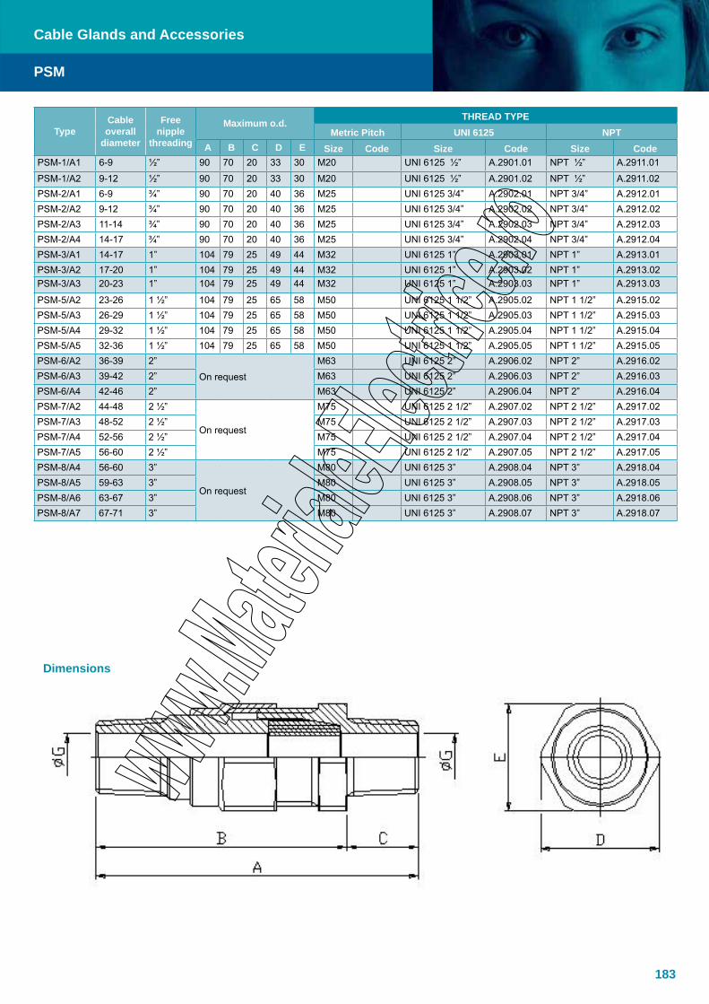
183
PSM
Cable Glands and Accessories
Dimensions
TypeCable overall
diameter
Free nipple
threading
Maximum o.d.THREAD TYPE
Metric Pitch UNI 6125 NPTA B C D E Size Code Size Code Size Code
PSM-1/A1 6-9 ½” 90 70 20 33 30 M20 UNI 6125 ½” A.2901.01 NPT ½” A.2911.01
PSM-1/A2 9-12 ½” 90 70 20 33 30 M20 UNI 6125 ½” A.2901.02 NPT ½” A.2911.02PSM-2/A1 6-9 ¾” 90 70 20 40 36 M25 UNI 6125 3/4” A.2902.01 NPT 3/4” A.2912.01PSM-2/A2 9-12 ¾” 90 70 20 40 36 M25 UNI 6125 3/4” A.2902.02 NPT 3/4” A.2912.02PSM-2/A3 11-14 ¾” 90 70 20 40 36 M25 UNI 6125 3/4” A.2902.03 NPT 3/4” A.2912.03PSM-2/A4 14-17 ¾” 90 70 20 40 36 M25 UNI 6125 3/4” A.2902.04 NPT 3/4” A.2912.04PSM-3/A1 14-17 1” 104 79 25 49 44 M32 UNI 6125 1” A.2903.01 NPT 1” A.2913.01PSM-3/A2 17-20 1” 104 79 25 49 44 M32 UNI 6125 1” A.2903.02 NPT 1” A.2913.02PSM-3/A3 20-23 1” 104 79 25 49 44 M32 UNI 6125 1” A.2903.03 NPT 1” A.2913.03
PSM-5/A2 23-26 1 ½” 104 79 25 65 58 M50 UNI 6125 1 1/2” A.2905.02 NPT 1 1/2” A.2915.02PSM-5/A3 26-29 1 ½” 104 79 25 65 58 M50 UNI 6125 1 1/2” A.2905.03 NPT 1 1/2” A.2915.03PSM-5/A4 29-32 1 ½” 104 79 25 65 58 M50 UNI 6125 1 1/2” A.2905.04 NPT 1 1/2” A.2915.04PSM-5/A5 32-36 1 ½” 104 79 25 65 58 M50 UNI 6125 1 1/2” A.2905.05 NPT 1 1/2” A.2915.05PSM-6/A2 36-39 2”
On request
M63 UNI 6125 2” A.2906.02 NPT 2” A.2916.02PSM-6/A3 39-42 2” M63 UNI 6125 2” A.2906.03 NPT 2” A.2916.03PSM-6/A4 42-46 2” M63 UNI 6125 2” A.2906.04 NPT 2” A.2916.04PSM-7/A2 44-48 2 ½”
On request
M75 UNI 6125 2 1/2” A.2907.02 NPT 2 1/2” A.2917.02PSM-7/A3 48-52 2 ½” M75 UNI 6125 2 1/2” A.2907.03 NPT 2 1/2” A.2917.03PSM-7/A4 52-56 2 ½” M75 UNI 6125 2 1/2” A.2907.04 NPT 2 1/2” A.2917.04PSM-7/A5 56-60 2 ½” M75 UNI 6125 2 1/2” A.2907.05 NPT 2 1/2” A.2917.05PSM-8/A4 56-60 3”
On request
M80 UNI 6125 3” A.2908.04 NPT 3” A.2918.04PSM-8/A5 59-63 3” M80 UNI 6125 3” A.2908.05 NPT 3” A.2918.05PSM-8/A6 63-67 3” M80 UNI 6125 3” A.2908.06 NPT 3” A.2918.06PSM-8/A7 67-71 3” M80 UNI 6125 3” A.2908.07 NPT 3” A.2918.07
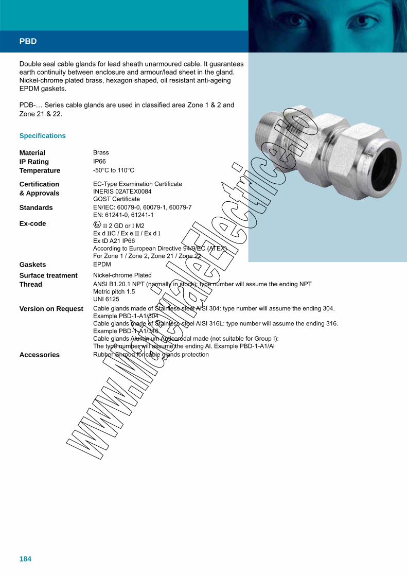
184
Double seal cable glands for lead sheath unarmoured cable. It guarantees earth continuity between enclosure and armour/lead sheet in the gland. Nickel-chrome plated brass, hexagon shaped, oil resistant anti-ageing EPDM gaskets.
PDB-… Series cable glands are used in classified area Zone 1 & 2 and Zone 21 & 22.
Specifications
Material BrassIP Rating IP66Temperature -50°C to 110°C
Certification & Approvals
EC-Type Examination Certificate INERIS 02ATEX0084GOST Certificate
Standards EN/IEC: 60079-0, 60079-1, 60079-7 EN: 61241-0, 61241-1
Ex-code II 2 GD or I M2Ex d IIC / Ex e II / Ex d IEx tD A21 IP66According to European Directive 94/9/EC (ATEX)For Zone 1 / Zone 2, Zone 21 / Zone 22
Gaskets EPDM
Surface treatment Nickel-chrome PlatedThread ANSI B1.20.1 NPT (normally in stock): type number will assume the ending NPT
Metric pitch 1.5UNI 6125
Version on Request Cable glands made of Stainless steel AISI 304: type number will assume the ending 304. Example PBD-1-A1/304Cable glands made of Stainless steel AISI 316L: type number will assume the ending 316. Example PBD-1-A1/316Cable glands Aluminium Anticorodal made (not suitable for Group I): The type number will assume the ending Al. Example PBD-1-A1/Al
Accessories Rubber Shroud for cable glands protection
PBD
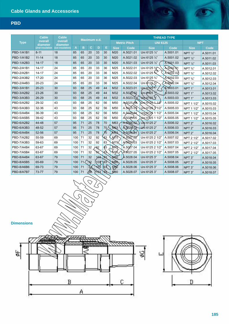
185
PBD
Cable Glands and Accessories
Dimensions
TypeCable overall
diameter(2nd insulation
Cable overall
diameter(1st insulation)
Maximum o.d.THREAD TYPE
Metric Pitch UNI 6125 NPTA B C D E Size Code Size Code Size Code
PBD-1/A1B1 8-11 18 85 65 20 33 30 M20 A.5021.01 Uni 6125 ½” A.5001.01 NPT ½” A.5011.01PBD-1/A1B2 11-14 18 85 65 20 33 30 M20 A.5021.02 Uni 6125 ½” A.5001.02 NPT ½” A.5011.02PBD-1/A2B3 14-17 18 85 65 20 33 30 M20 A.5021.03 Uni 6125 ½” A.5001.03 NPT ½” A.5011.03PBD-2/A1B1 14-17 24 85 65 20 33 36 M25 A.5022.01 Uni 6125 ¾” A.5002.01 NPT ¾” A.5012.01PBD-2/A2B1 14-17 24 85 65 20 33 36 M25 A.5022.02 Uni 6125 ¾” A.5002.02 NPT ¾” A.5012.02PBD-2/A3B2 17-20 24 85 65 20 33 36 M25 A.5022.03 Uni 6125 ¾” A.5002.03 NPT ¾” A.5012.03PBD-2/A4B3 20-23 24 85 65 20 33 36 M25 A.5022.04 Uni 6125 ¾” A.5002.04 NPT ¾” A.5012.04PBD-3/A1B1 20-23 30 93 68 25 49 44 M32 A.5023.01 Uni 6125 1” A.5003.01 NPT 1” A.5013.01PBD-3/A2B2 23-26 30 93 68 25 49 44 M32 A.5023.02 Uni 6125 1” A.5003.02 NPT 1” A.5013.02PBD-3/A3B3 26-29 30 93 68 25 49 44 M32 A.5023.03 Uni 6125 1” A.5003.03 NPT 1” A.5013.03PBD-5/A2B2 29-32 43 93 68 25 62 56 M50 A.5025.02 Uni 6125 1 1/2” A.5005.02 NPT 1 1/2” A.5015.02PBD-5/A3B3 32-36 43 93 68 25 62 56 M50 A.5025.03 Uni 6125 1 1/2” A.5005.03 NPT 1 1/2” A.5015.03PBD-5/A4B4 36-39 43 93 68 25 62 56 M50 A.5025.04 Uni 6125 1 1/2” A.5005.04 NPT 1 1/2” A.5015.04PBD-5/A5B5 39-42 43 93 68 25 62 56 M50 A.5025.05 Uni 6125 1 1/2” A.5005.05 NPT 1 1/2” A.5015.05PBD-6/A2B2 44-48 57 95 71 25 78 70 M63 A.5026.02 Uni 6125 2” A.5006.02 NPT 2” A.5016.02PBD-6/A3B3 48-52 57 95 71 25 78 70 M63 A.5026.03 Uni 6125 2” A.5006.03 NPT 2” A.5016.03PBD-6/A4B4 52-56 57 95 71 25 78 70 M63 A.5026.04 Uni 6125 2” A.5006.04 NPT 2” A.5016.04PBD-7/A2B2 55-59 69 100 71 32 92 83 M75 A.5027.02 Uni 6125 2 1/2” A.5007.02 NPT 2 1/2” A.5017.02PBD-7/A3B3 59-63 69 100 71 32 92 83 M75 A.5027.03 Uni 6125 2 1/2” A.5007.03 NPT 2 1/2” A.5017.03PBD-7/A4B4 63-67 69 100 71 32 92 83 M75 A.5027.04 Uni 6125 2 1/2” A.5007.04 NPT 2 1/2” A.5017.04PBD-7/A5B4 63-67 69 100 71 32 92 83 M75 A.5027.05 Uni 6125 2 1/2” A.5007.05 NPT 2 1/2” A.5017.05PBD-8/A4B4 63-67 79 100 71 32 103 93 M80 A.5028.04 Uni 6125 3” A.5008.04 NPT 3” A.5018.04PBD-8/A5B5 65-69 79 100 71 32 103 93 M80 A.5028.05 Uni 6125 3” A.5008.05 NPT 3” A.5018.05PBD-8/A6B6 69-73 79 100 71 32 103 93 M80 A.5028.06 Uni 6125 3” A.5008.06 NPT 3” A.5018.06PBD-8/A7B7 73-77 79 100 71 32 103 93 M80 A.5028.07 Uni 6125 3” A.5008.07 NPT 3” A.5018.07
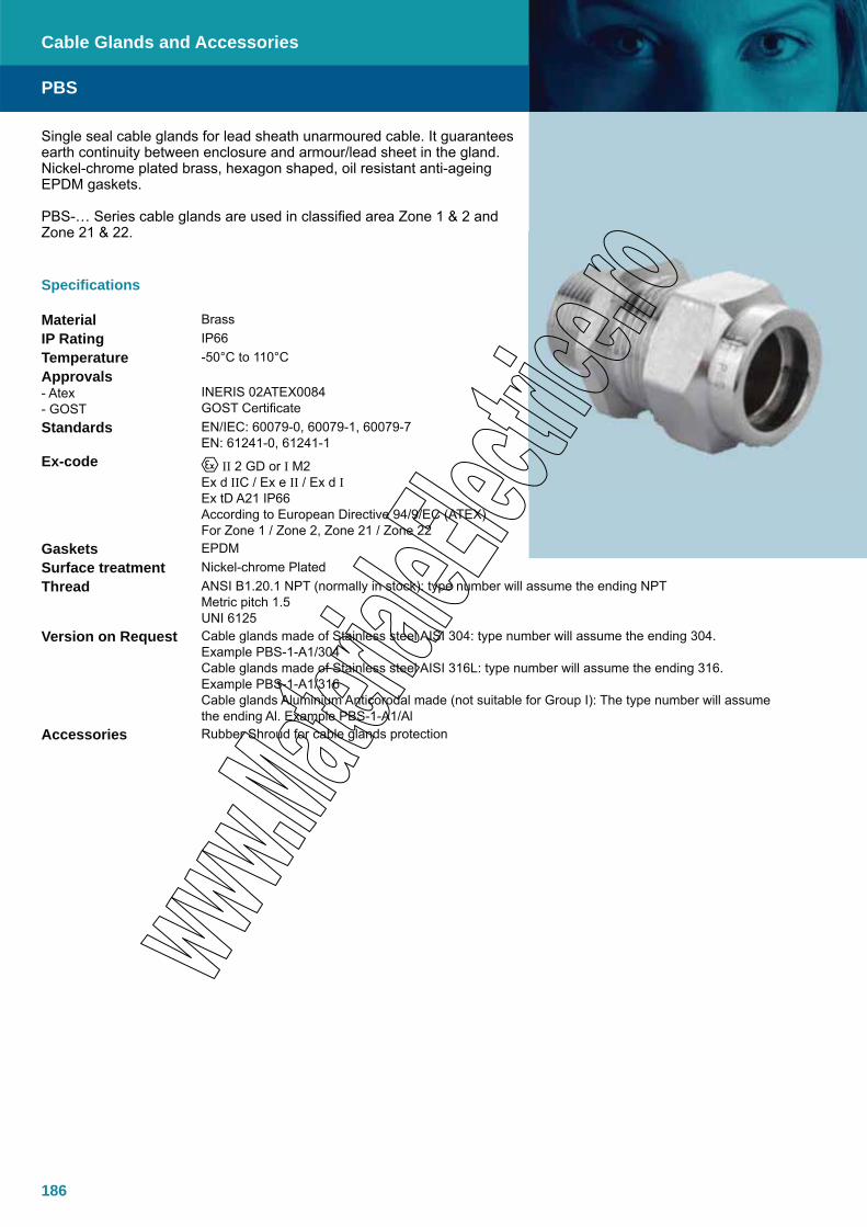
186
Single seal cable glands for lead sheath unarmoured cable. It guarantees earth continuity between enclosure and armour/lead sheet in the gland. Nickel-chrome plated brass, hexagon shaped, oil resistant anti-ageing EPDM gaskets.
PBS-… Series cable glands are used in classified area Zone 1 & 2 and Zone 21 & 22.
Specifications
Material BrassIP Rating IP66Temperature -50°C to 110°CApprovals- Atex- GOST
INERIS 02ATEX0084GOST Certificate
Standards EN/IEC: 60079-0, 60079-1, 60079-7EN: 61241-0, 61241-1
Ex-code II 2 GD or I M2Ex d IIC / Ex e II / Ex d IEx tD A21 IP66According to European Directive 94/9/EC (ATEX)For Zone 1 / Zone 2, Zone 21 / Zone 22
Gaskets EPDMSurface treatment Nickel-chrome PlatedThread ANSI B1.20.1 NPT (normally in stock): type number will assume the ending NPT
Metric pitch 1.5UNI 6125
Version on Request Cable glands made of Stainless steel AISI 304: type number will assume the ending 304. Example PBS-1-A1/304Cable glands made of Stainless steel AISI 316L: type number will assume the ending 316. Example PBS-1-A1/316Cable glands Aluminium Anticorodal made (not suitable for Group I): The type number will assume the ending Al. Example PBS-1-A1/Al
Accessories Rubber Shroud for cable glands protection
PBS
Cable Glands and Accessories

187
PBS
Cable Glands and Accessories
Dimensions
TypeCable under
armour(inner seal)
ØExternal
cableMaximum o.d.
THREAD TYPEMetric Pitch
UNI 6125 NPTF A B C D E Size Code Size Code Size Code
PBS-1/A1 6-9 18 62 42 20 33 30 Metrico M20 A.1891.01 UNI 6125 ½” A.1871.01 NPT 1/2” A.1881.01
PBS-1/A2 9-12 18 62 42 20 33 30 Metrico M20 A.1891.02 UNI 6125 ½” A.1871.02 NPT 1/2” A.1881.02
PBS-2/A1 6-9 24 62 42 20 40 36 Metrico M25 A.1892.01 UNI 6125 3/4” A.1872.01 NPT 3/4” A.1882.01
PBS-2/A2 9-12 24 62 42 20 40 36 Metrico M25 A.1892.02 UNI 6125 3/4” A.1872.02 NPT 3/4” A.1882.02PBS-2/A3 11-14 24 62 42 20 40 36 Metrico M25 A.1892.03 UNI 6125 3/4” A.1872.03 NPT 3/4” A.1882.03PBS-2/A4 14-17 24 62 42 20 40 36 Metrico M25 A.1892.04 UNI 6125 3/4” A.1872.04 NPT 3/4” A.1882.04PBS-3/A1 14-17 30 70 45 25 49 44 Metrico M32 A.1893.01 UNI 6125 1” A.1873.01 NPT 1” A.1883.01PBS-3/A2 17-20 30 70 45 25 49 44 Metrico M32 A.1893.02 UNI 6125 1” A.1873.02 NPT 1” A.1883.02PBS-3/A3 20-23 30 70 45 25 49 44 Metrico M32 A.1893.03 UNI 6125 1” A.1873.03 NPT 1” A.1883.03PBS-5/A2 23-26 43 70 45 25 62 56 Metrico M50 A.1895.02 UNI 6125 1 1/2” A.1875.02 NPT 1 1/2” A.1885.02PBS-5/A3 26-29 43 70 45 25 62 56 Metrico M50 A.1895.03 UNI 6125 1 1/2” A.1875.03 NPT 1 1/2” A.1885.03
PBS-5/A4 29-32 43 70 45 25 62 56 Metrico M50 A.1895.04 UNI 6125 1 1/2” A.1875.04 NPT 1 1/2” A.1885.04PBS-5/A5 32-36 43 70 45 25 62 56 Metrico M50 A.1895.05 UNI 6125 1 1/2” A.1875.05 NPT 1 1/2” A.1885.05PBS-6/A2 36-39 57 72 46 25 78 70 Metrico M63 A.1896.02 UNI 6125 2” A.1876.02 NPT 2” A.1886.02PBS-6/A3 39-42 57 72 46 25 78 70 Metrico M63 A.1896.03 UNI 6125 2” A.1876.03 NPT 2” A.1886.03PBS-6/A4 42-46 57 72 46 25 78 70 Metrico M63 A.1896.04 UNI 6125 2” A.1876.04 NPT 2” A.1886.04PBS-7/A2 44-48 69 78 46 25 78 70 Metrico M75 A.1897.02 UNI 6125 2 1/2” A.1877.02 NPT 2 1/2” A.1887.02PBS-7/A3 48-52 69 78 46 25 78 70 Metrico M75 A.1897.03 UNI 6125 2 1/2” A.1877.03 NPT 2 1/2” A.1887.03PBS-7/A4 52-56 69 78 46 25 78 70 Metrico M75 A.1897.04 UNI 6125 2 1/2” A.1877.04 NPT 2 1/2” A.1887.04PBS-7/A5 56-60 69 78 46 25 78 70 Metrico M75 A.1897.05 UNI 6125 2 1/2” A.1877.05 NPT 2 1/2” A.1887.05PBS-8/A4 56-60 79 78 46 32 103 93 Metrico M80 A.1898.04 UNI 6125 3” A.1878.04 NPT 3” A.1888.04PBS-8/A5 59-63 79 78 46 32 103 93 Metrico M80 A.1898.05 UNI 6125 3” A.1878.05 NPT 3” A.1888.05PBS-8/A6 63-67 79 78 46 32 103 93 Metrico M80 A.1898.06 UNI 6125 3” A.1878.06 NPT 3” A.1888.06PBS-8/A7 67-71 79 78 46 32 103 93 Metrico M80 A.1898.07 UNI 6125 3” A.1878.07 NPT 3” A.1888.07

188
Double seal cable glands for lead sheath armoured cable. It guarantees earth continuity between enclosure and armour/lead sheet in the gland. Nickel-chrome plated brass, hexagon shaped, oil resistant anti-ageing EPDM gaskets.
PDB-… Series cable glands are used in classified area Zone 1 & 2 and Zone 21 & 22.
Specifications
Material BrassIP Rating IP66Temperature -50°C to 110°C
Approvals- Atex- GOST
INERIS 02ATEX0084GOST Certificate
Standards EN/IEC: 60079-0, 60079-1, 60079-7EN: 61241-0, 61241-1
Ex-code II 2 GD or I M2Ex d IIC / Ex e II / Ex d IEx tD A21 IP66According to European Directive 94/9/EC (ATEX)For Zone 1 / Zone 2, Zone 21 / Zone 22
Gaskets EPDMSurface treatment Nickel-chrome PlatedThread ANSI B1.20.1 NPT (normally in stock): type number will assume the ending NPT
Metric pitch 1.5UNI 6125
Version on Request Cable glands made of Stainless steel AISI 304: type number will assume the ending 304. Example PDB-1-A1/304Cable glands made of Stainless steel AISI 316L: type number will assume the ending 316. Example PDB-1-A1/316Cable glands Aluminium Anticorodal made (not suitable for Group I): The type number will assume the ending Al. Example PDB-1-A1/Al
Accessories Rubber Shroud for cable glands protection
Note All cable glands of a.m. series will be supplied with armouring-ring and cone nickel-chrome plated brass made (if not differently specified in offer or in order acknowledgment)
PDB
Cable Glands and Accessories
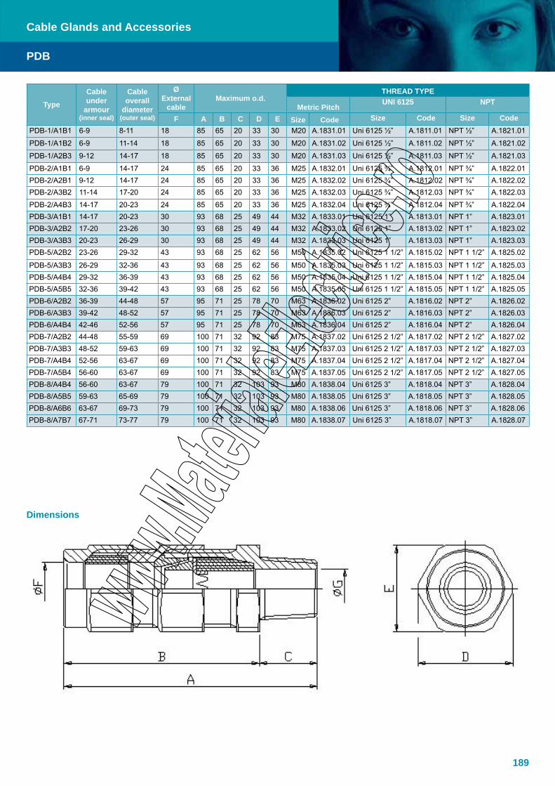
189
PDB
Cable Glands and Accessories
Dimensions
TypeCable under
armour(inner seal)
Cable overall
diameter(outer seal)
ØExternal
cableMaximum o.d.
THREAD TYPE
Metric PitchUNI 6125 NPT
F A B C D E Size Code Size Code Size CodePDB-1/A1B1 6-9 8-11 18 85 65 20 33 30 M20 A.1831.01 Uni 6125 ½” A.1811.01 NPT ½” A.1821.01
PDB-1/A1B2 6-9 11-14 18 85 65 20 33 30 M20 A.1831.02 Uni 6125 ½” A.1811.02 NPT ½” A.1821.02
PDB-1/A2B3 9-12 14-17 18 85 65 20 33 30 M20 A.1831.03 Uni 6125 ½” A.1811.03 NPT ½” A.1821.03
PDB-2/A1B1 6-9 14-17 24 85 65 20 33 36 M25 A.1832.01 Uni 6125 ¾” A.1812.01 NPT ¾” A.1822.01PDB-2/A2B1 9-12 14-17 24 85 65 20 33 36 M25 A.1832.02 Uni 6125 ¾” A.1812.02 NPT ¾” A.1822.02PDB-2/A3B2 11-14 17-20 24 85 65 20 33 36 M25 A.1832.03 Uni 6125 ¾” A.1812.03 NPT ¾” A.1822.03
PDB-2/A4B3 14-17 20-23 24 85 65 20 33 36 M25 A.1832.04 Uni 6125 ¾” A.1812.04 NPT ¾” A.1822.04PDB-3/A1B1 14-17 20-23 30 93 68 25 49 44 M32 A.1833.01 Uni 6125 1” A.1813.01 NPT 1” A.1823.01PDB-3/A2B2 17-20 23-26 30 93 68 25 49 44 M32 A.1833.02 Uni 6125 1” A.1813.02 NPT 1” A.1823.02PDB-3/A3B3 20-23 26-29 30 93 68 25 49 44 M32 A.1833.03 Uni 6125 1” A.1813.03 NPT 1” A.1823.03PDB-5/A2B2 23-26 29-32 43 93 68 25 62 56 M50 A.1835.02 Uni 6125 1 1/2” A.1815.02 NPT 1 1/2” A.1825.02
PDB-5/A3B3 26-29 32-36 43 93 68 25 62 56 M50 A.1835.03 Uni 6125 1 1/2” A.1815.03 NPT 1 1/2” A.1825.03PDB-5/A4B4 29-32 36-39 43 93 68 25 62 56 M50 A.1835.04 Uni 6125 1 1/2” A.1815.04 NPT 1 1/2” A.1825.04PDB-5/A5B5 32-36 39-42 43 93 68 25 62 56 M50 A.1835.05 Uni 6125 1 1/2” A.1815.05 NPT 1 1/2” A.1825.05PDB-6/A2B2 36-39 44-48 57 95 71 25 78 70 M63 A.1836.02 Uni 6125 2” A.1816.02 NPT 2” A.1826.02PDB-6/A3B3 39-42 48-52 57 95 71 25 78 70 M63 A.1836.03 Uni 6125 2” A.1816.03 NPT 2” A.1826.03PDB-6/A4B4 42-46 52-56 57 95 71 25 78 70 M63 A.1836.04 Uni 6125 2” A.1816.04 NPT 2” A.1826.04PDB-7/A2B2 44-48 55-59 69 100 71 32 92 83 M75 A.1837.02 Uni 6125 2 1/2” A.1817.02 NPT 2 1/2” A.1827.02PDB-7/A3B3 48-52 59-63 69 100 71 32 92 83 M75 A.1837.03 Uni 6125 2 1/2” A.1817.03 NPT 2 1/2” A.1827.03PDB-7/A4B4 52-56 63-67 69 100 71 32 92 83 M75 A.1837.04 Uni 6125 2 1/2” A.1817.04 NPT 2 1/2” A.1827.04PDB-7/A5B4 56-60 63-67 69 100 71 32 92 83 M75 A.1837.05 Uni 6125 2 1/2” A.1817.05 NPT 2 1/2” A.1827.05PDB-8/A4B4 56-60 63-67 79 100 71 32 103 93 M80 A.1838.04 Uni 6125 3” A.1818.04 NPT 3” A.1828.04PDB-8/A5B5 59-63 65-69 79 100 71 32 103 93 M80 A.1838.05 Uni 6125 3” A.1818.05 NPT 3” A.1828.05PDB-8/A6B6 63-67 69-73 79 100 71 32 103 93 M80 A.1838.06 Uni 6125 3” A.1818.06 NPT 3” A.1828.06PDB-8/A7B7 67-71 73-77 79 100 71 32 103 93 M80 A.1838.07 Uni 6125 3” A.1818.07 NPT 3” A.1828.07
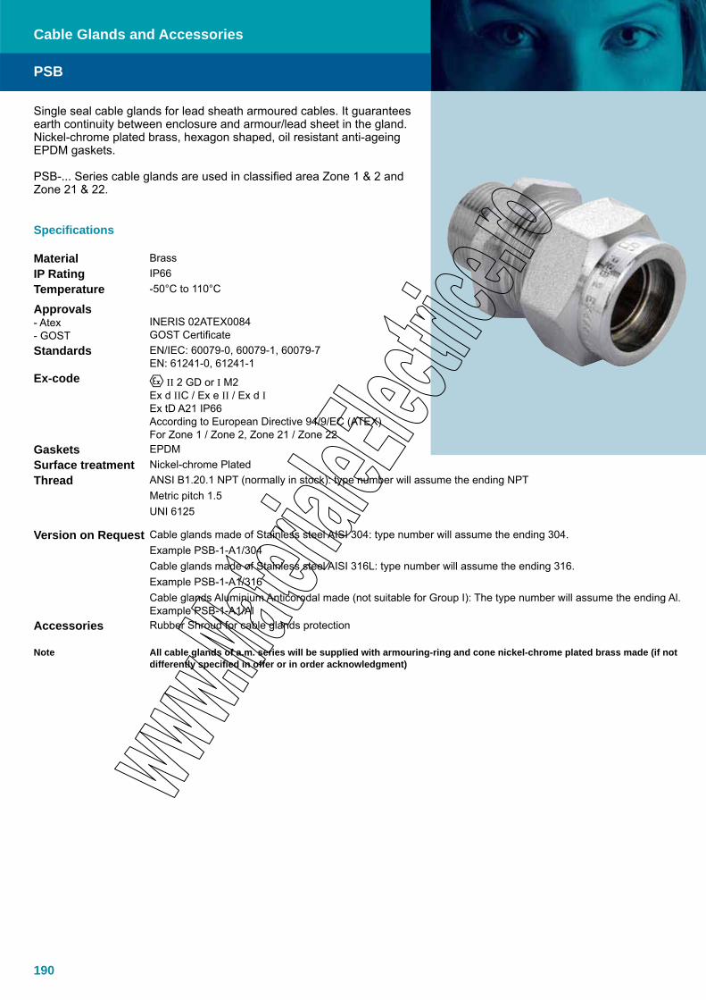
190
Single seal cable glands for lead sheath armoured cables. It guarantees earth continuity between enclosure and armour/lead sheet in the gland. Nickel-chrome plated brass, hexagon shaped, oil resistant anti-ageing EPDM gaskets.
PSB-... Series cable glands are used in classified area Zone 1 & 2 and Zone 21 & 22.
Specifications
Material BrassIP Rating IP66Temperature -50°C to 110°C
Approvals- Atex- GOST
INERIS 02ATEX0084GOST Certificate
Standards EN/IEC: 60079-0, 60079-1, 60079-7EN: 61241-0, 61241-1
Ex-code II 2 GD or I M2Ex d IIC / Ex e II / Ex d IEx tD A21 IP66According to European Directive 94/9/EC (ATEX)For Zone 1 / Zone 2, Zone 21 / Zone 22
Gaskets EPDMSurface treatment Nickel-chrome Plated Thread ANSI B1.20.1 NPT (normally in stock): type number will assume the ending NPT
Metric pitch 1.5UNI 6125
Version on Request Cable glands made of Stainless steel AISI 304: type number will assume the ending 304. Example PSB-1-A1/304Cable glands made of Stainless steel AISI 316L: type number will assume the ending 316. Example PSB-1-A1/316Cable glands Aluminium Anticorodal made (not suitable for Group I): The type number will assume the ending Al. Example PSB-1-A1/Al
Accessories Rubber Shroud for cable glands protection
Note All cable glands of a.m. series will be supplied with armouring-ring and cone nickel-chrome plated brass made (if not differently specified in offer or in order acknowledgment)
PSB
Cable Glands and Accessories

191
PSB
Cable Glands and Accessories
Dimensions
TypeCable under
armour (inner seal)
Ø External
cableMaximum o.d.
THREAD TYPE
Metric Pitch UNI 6125 NPTF A B C D E Size Code Size Code Size Code
PSB-1/A1 6-9 18 62 42 20 33 30 M20 A.5121.01 UNI 6125 ½” A.5101.01 NPT 1/2” A.5111.01
PSB-1/A2 9-12 18 62 42 20 33 30 M20 A.5121.02 UNI 6125 ½” A.5101.02 NPT 1/2” A.5111.02
PSB-2/A1 6-9 24 62 42 20 40 36 M25 A.5122.01 UNI 6125 3/4” A.5102.01 NPT 3/4” A.5112.01
PSB-2/A2 9-12 24 62 42 20 40 36 M25 A.5122.02 UNI 6125 3/4” A.5102.02 NPT 3/4” A.5112.02PSB-2/A3 11-14 24 62 42 20 40 36 M25 A.5122.03 UNI 6125 3/4” A.5102.03 NPT 3/4” A.5112.03PSB-2/A4 14-17 24 62 42 20 40 36 M25 A.5122.04 UNI 6125 3/4” A.5102.04 NPT 3/4” A.5112.04PSB-3/A1 14-17 30 70 45 25 49 44 M32 A.5123.01 UNI 6125 1” A.5103.01 NPT 1” A.5113.01PSB-3/A2 17-20 30 70 45 25 49 44 M32 A.5123.02 UNI 6125 1” A.5103.02 NPT 1” A.5113.02PSB-3/A3 20-23 30 70 45 25 49 44 M32 A.5123.03 UNI 6125 1” A.5103.03 NPT 1” A.5113.03PSB-5/A2 23-26 43 70 45 25 49 44 M50 A.5125.02 UNI 6125 1 1/2” A.5105.02 NPT 1 1/2” A.5115.02PSB-5/A3 26-29 43 70 45 25 49 44 M50 A.5125.03 UNI 6125 1 1/2” A.5105.03 NPT 1 1/2” A.5115.03
PSB-5/A4 29-32 43 70 45 25 49 44 M50 A.5125.04 UNI 6125 1 1/2” A.5105.04 NPT 1 1/2” A.5115.04PSB-5/A5 32-36 43 70 45 25 49 44 M50 A.5125.05 UNI 6125 1 1/2” A.5105.05 NPT 1 1/2” A.5115.05PSB-6/A2 36-39 57 72 46 25 78 70 M63 A.5126.02 UNI 6125 2” A.5106.02 NPT 2” A.5116.02PSB-6/A3 39-42 57 72 46 25 78 70 M63 A.5126.03 UNI 6125 2” A.5106.03 NPT 2” A.5116.03PSB-6/A4 42-46 57 72 46 25 78 70 M63 A.5126.04 UNI 6125 2” A.5106.04 NPT 2” A.5116.04PSB-7/A2 44-48 69 78 46 32 92 83 M75 A.5127.02 UNI 6125 2 1/2” A.5107.02 NPT 2 1/2” A.5117.02PSB-7/A3 48-52 69 78 46 32 92 83 M75 A.5127.03 UNI 6125 2 1/2” A.5107.03 NPT 2 1/2” A.5117.03PSB-7/A4 52-56 69 78 46 32 92 83 M75 A.5127.04 UNI 6125 2 1/2” A.5107.04 NPT 2 1/2” A.5117.04PSB-7/A5 56-60 69 78 46 32 92 83 M75 A.5127.05 UNI 6125 2 1/2” A.5107.05 NPT 2 1/2” A.5117.05PSB-8/A4 56-60 79 78 46 32 103 93 M80 A.5128.04 UNI 6125 3” A.5108.04 NPT 3” A.5118.04PSB-8/A5 59-63 79 78 46 32 103 93 M80 A.5128.05 UNI 6125 3” A.5108.05 NPT 3” A.5118.05PSB-8/A6 63-67 79 78 46 32 103 93 M80 A.5128.06 UNI 6125 3” A.5108.06 NPT 3” A.5118.06PSB-8/A7 67-71 79 78 46 32 103 93 M80 A.5128.07 UNI 6125 3” A.5108.07 NPT 3” A.5118.07
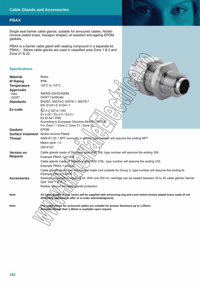
192
Specifications
Material BrassIP Rating IP66Temperature -50°C to 110°CApprovals- Atex- GOST
INERIS 02ATEX0084GOST Certificate
Standards EN/IEC: 60079-0, 60079-1, 60079-7EN: 61241-0, 61241-1
Ex-code II 2 GD or I M2Ex d IIC / Ex e II / Ex d IEx tD A21 IP66According to European Directive 94/9/EC (ATEX)For Zone 1 / Zone 2, Zone 21 / Zone 22
Gaskets EPDMSurface treatment Nickel-chrome PlatedThread ANSI B1.20.1 NPT (normally in stock): type number will assume the ending NPT
Metric pitch 1.5UNI 6125
Version on Request
Cable glands made of Stainless steel AISI 304: type number will assume the ending 304. Example PBAX-1-A1/304Cable glands made of Stainless steel AISI 316L: type number will assume the ending 316. Example PBAX-1-A1/316Cable glands Aluminium Anticorodal made (not suitable for Group I): type number will assume the ending Al. Example PBAX-1-A1/Al
Accessories Sealing compound in separate kit. With one 200 ml. cartridge can be sealed between 30 to 35 cable glands “barrier type” size 1 to 3.Rubber Shroud for cable glands protection
Note All cable glands of a.m. series will be supplied with armouring-ring and cone nickel-chrome plated brass made (if not differently specified in offer or in order acknowledgment)
Note The cable glands for armoured cables are suitable for armour thickness up to 1.25mm. Armours thicker than 1.26mm is available upon request
Single seal barrier cable glands, suitable for armoured cables. Nickel-chrome plated brass, hexagon shaped, oil resistant anti-ageing EPDM gaskets.
PBAX is a barrier cable gland with sealing compound in a separate kit. PBAX-... Series cable glands are used in classified area Zone 1 & 2 and Zone 21 & 22.
PBAX
Cable Glands and Accessories
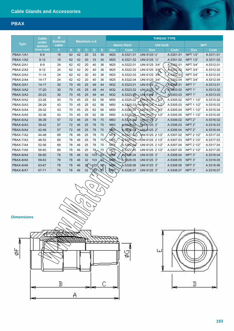
193
PBAX
Cable Glands and Accessories
Dimensions
TypeCable under
armour(inner seal)
ØExternal
cableMaximum o.d.
THREAD TYPE
Metric Pitch UNI 6125 NPTF A B C D E Size Code Size Code Size Code
PBAX-1/A1 6-9 18 62 42 20 33 30 M20 A.5321.01 UNI 6125 ½” A.5301.01 NPT 1/2” A.5311.01PBAX-1/A2 9-12 18 62 42 20 33 30 M20 A.5321.02 UNI 6125 ½” A.5301.02 NPT 1/2” A.5311.02PBAX-2/A1 6-9 24 62 42 20 40 36 M25 A.5322.01 UNI 6125 3/4” A.5302.01 NPT 3/4” A.5312.01PBAX-2/A2 9-12 24 62 42 20 40 36 M25 A.5322.02 UNI 6125 3/4” A.5302.02 NPT 3/4” A.5312.02PBAX-2/A3 11-14 24 62 42 20 40 36 M25 A.5322.03 UNI 6125 3/4” A.5302.03 NPT 3/4” A.5312.03PBAX-2/A4 14-17 24 62 42 20 40 36 M25 A.5322.04 UNI 6125 3/4” A.5302.04 NPT 3/4” A.5312.04PBAX-3/A1 14-17 30 70 45 25 49 44 M32 A.5323.01 UNI 6125 1” A.5303.01 NPT 1” A.5313.01PBAX-3/A2 17-20 30 70 45 25 49 44 M32 A.5323.02 UNI 6125 1” A.5303.02 NPT 1” A.5313.02PBAX-3/A3 20-23 30 70 45 25 49 44 M32 A.5323.03 UNI 6125 1” A.5303.03 NPT 1” A.5313.03PBAX-5/A2 23-26 43 70 45 25 62 56 M50 A.5325.02 UNI 6125 1 1/2” A.5305.02 NPT 1 1/2” A.5315.02PBAX-5/A3 26-29 43 70 45 25 62 56 M50 A.5325.03 UNI 6125 1 1/2” A.5305.03 NPT 1 1/2” A.5315.03PBAX-5/A4 29-32 43 70 45 25 62 56 M50 A.5325.04 UNI 6125 1 1/2” A.5305.04 NPT 1 1/2” A.5315.04PBAX-5/A5 32-36 43 70 45 25 62 56 M50 A.5325.05 UNI 6125 1 1/2” A.5305.05 NPT 1 1/2” A.5315.05PBAX-6/A2 36-39 57 72 46 25 78 70 M63 A.5326.02 UNI 6125 2” A.5306.02 NPT 2” A.5316.02PBAX-6/A3 39-42 57 72 46 25 78 70 M63 A.5326.03 UNI 6125 2” A.5306.03 NPT 2” A.5316.03PBAX-6/A4 42-46 57 72 46 25 78 70 M63 A.5326.04 UNI 6125 2” A.5306.04 NPT 2” A.5316.04PBAX-7/A2 44-48 69 78 46 25 78 70 M75 A.5327.02 UNI 6125 2 1/2” A.5307.02 NPT 2 1/2” A.5317.02PBAX-7/A3 48-52 69 78 46 25 78 70 M75 A.5327.03 UNI 6125 2 1/2” A.5307.03 NPT 2 1/2” A.5317.03PBAX-7/A4 52-56 69 78 46 25 78 70 M75 A.5327.04 UNI 6125 2 1/2” A.5307.04 NPT 2 1/2” A.5317.04PBAX-7/A5 56-60 69 78 46 25 78 70 M75 A.5327.05 UNI 6125 2 1/2” A.5307.05 NPT 2 1/2” A.5317.05PBAX-8/A4 56-60 79 78 46 32 103 93 M80 A.5328.04 UNI 6125 3” A.5308.04 NPT 3” A.5318.04PBAX-8/A5 59-63 79 78 46 32 103 93 M80 A.5328.05 UNI 6125 3” A.5308.05 NPT 3” A.5318.05
PBAX-8/A6 63-67 79 78 46 32 103 93 M80 A.5328.06 UNI 6125 3” A.5308.06 NPT 3” A.5318.06PBAX-8/A7 67-71 79 78 46 32 103 93 M80 A.5328.07 UNI 6125 3” A.5308.07 NPT 3” A.5318.07

194
Double seal cable glands, suitable for unarmoured cables. Nickel-chrome plated brass, hexagon shaped, oil resistant anti-ageing EPDM gaskets.
PND-... Series cable glands are used in classified area Zone 1 & 2 and Zone 21 & 22.
Specifications
Material BrassIP Rating IP66Temperature -50°C to 110°CApprovals- Atex- GOST
INERIS 02ATEX0084GOST Certificate
Standards EN/IEC: 60079-0, 60079-1, 60079-7EN: 61241-0, 61241-1
Ex-code
II 2 GD or I M2Ex d IIC / Ex e II / Ex d IEx tD A21 IP66According to European Directive 94/9/EC (ATEX)For Zone 1 / Zone 2, Zone 21 / Zone 22
Gaskets EPDMSurface treatment Nickel-chrome Plated
ThreadANSI B1.20.1 NPT (normally in stock): type number will assume the ending NPTMetric pitch 1.5UNI 6125
Version on Request Cable glands made of Stainless steel AISI 304: type number will assume the ending 304. Example PND-1-A1/304 Cable glands made of Stainless steel AISI 316L: type number will assume the ending 316. Example PND-1-A1/316Cable glands Aluminium Anticorodal made (not suitable for Group I): the type number will assume the ending Al. Example PND-1-A1/Al
Accessories Rubber Shroud for cable glands protection
PND
Cable Glands and Accessories

195
PND
Cable Glands and Accessories
Dimensions
TypeCable overall
diameter(2nd insulation)
Cable overall
diameter (1st insulation)
ØExternal
cableMaximum o.d.
THREAD TYPE
Metric Pitch UNI 6125 NPTF A B C D E Size Code Size Code Size Code
PND-1/A1B1 6-9 8-11 18 85 65 20 33 30 M20 A.5221.01 Uni 6125 ½” A.5201.01 NPT ½” A.5211.01PND-1/A1B2 6-9 11-14 18 85 65 20 33 30 M20 A.5221.02 Uni 6125 ½” A.5201.02 NPT ½” A.5211.02PND-1/A2B3 9-12 14-17 18 85 65 20 33 30 M20 A.5221.03 Uni 6125 ½” A.5201.03 NPT ½” A.5211.03PND-2/A1B1 6-9 14-17 24 85 65 20 33 36 M25 A.5222.01 Uni 6125 ¾” A.5202.01 NPT ¾” A.5212.01PND-2/A2B1 9-12 14-17 24 85 65 20 33 36 M25 A.5222.02 Uni 6125 ¾” A.5202.02 NPT ¾” A.5212.02PND-2/A3B2 11-14 17-20 24 85 65 20 33 36 M25 A.5222.03 Uni 6125 ¾” A.5202.03 NPT ¾” A.5212.03PND-2/A4B3 14-17 20-23 24 85 65 20 33 36 M25 A.5222.04 Uni 6125 ¾” A.5202.04 NPT ¾” A.5212.04PND-3/A1B1 14-17 20-23 30 93 68 25 49 44 M32 A.5223.01 Uni 6125 1” A.5203.01 NPT 1” A.5213.01PND-3/A2B2 17-20 23-26 30 93 68 25 49 44 M32 A.5223.02 Uni 6125 1” A.5203.02 NPT 1” A.5213.02PND-3/A3B3 20-23 26-29 30 93 68 25 49 44 M32 A.5223.03 Uni 6125 1” A.5203.03 NPT 1” A.5213.03PND-5/A2B2 23-26 29-32 43 93 68 25 62 56 M50 A.5225.02 Uni 6125 1 1/2” A.5205.02 NPT 1 1/2” A.5215.02PND-5/A3B3 26-29 32-36 43 93 68 25 62 56 M50 A.5225.03 Uni 6125 1 1/2” A.5205.03 NPT 1 1/2” A.5215.03PND-5/A4B4 29-32 36-39 43 93 68 25 62 56 M50 A.5225.04 Uni 6125 1 1/2” A.5205.04 NPT 1 1/2” A.5215.04PND-5/A5B5 32-36 39-42 43 93 68 25 62 56 M50 A.5225.05 Uni 6125 1 1/2” A.5205.05 NPT 1 1/2” A.5215.05PND-6/A2B2 36-39 44-48 57 95 71 25 78 70 M63 A.5226.02 Uni 6125 2” A.5206.02 NPT 2” A.5216.02PND-6/A3B3 39-42 48-52 57 95 71 25 78 70 M63 A.5226.03 Uni 6125 2” A.5206.03 NPT 2” A.5216.03PND-6/A4B4 42-46 52-56 57 95 71 25 78 70 M63 A.5226.04 Uni 6125 2” A.5206.04 NPT 2” A.5216.04PND-7/A2B2 44-48 55-59 69 100 71 32 92 83 M75 A.5227.02 Uni 6125 2 1/2” A.5207.02 NPT 2 1/2” A.5217.02PND-7/A3B3 48-52 59-63 69 100 71 32 92 83 M75 A.5227.03 Uni 6125 2 1/2” A.5207.03 NPT 2 1/2” A.5217.03PND-7/A4B4 52-56 63-67 69 100 71 32 92 83 M75 A.5227.04 Uni 6125 2 1/2” A.5207.04 NPT 2 1/2” A.5217.04PND-7/A5B4 56-60 63-67 69 100 71 32 92 83 M75 A.5227.05 Uni 6125 2 1/2” A.5207.05 NPT 2 1/2” A.5217.05PND-8/A4B4 56-60 63-67 79 100 71 32 103 93 M80 A.5228.04 Uni 6125 3” A.5208.04 NPT 3” A.5218.04PND-8/A5B5 59-63 65-69 79 100 71 32 103 93 M80 A.5228.05 Uni 6125 3” A.5208.05 NPT 3” A.5218.05PND-8/A6B6 63-67 69-73 79 100 71 32 103 93 M80 A.5228.06 Uni 6125 3” A.5208.06 NPT 3” A.5218.06
PND-8/A7B7 67-71 73-77 79 100 71 32 103 93 M80 A.5228.07 Uni 6125 3” A.5208.07 NPT 3” A.5218.07

196
Single seal cable glands, suitable for unarmoured cables. Nickel-chrome plated brass, hexagon shaped, oil resistant anti-ageing EPDM gaskets.
PNS-... Series cable glands are used in classified Area Zone 1 & 2 and Zone 21 & 22.
Specifications
Material BrassIP Rating IP66Temperature -50°C to 110°CApprovals- Atex- GOST
INERIS 02ATEX0084GOST Certificate
Standards EN/IEC: 60079-0, 60079-1, 60079-7EN: 61241-0, 61241-1
Ex-code II 2 GD or I M2Ex d IIC / Ex e II / Ex d IEx tD A21 IP66According to European Directive 94/9/EC (ATEX)For Zone 1 / Zone 2, Zone 21 / Zone 22
Gaskets EPDMSurface treatment Nickel-chrome PlatedThread ANSI B1.20.1 NPT (normally in stock): type number will assume the ending NPT
Metric pitch 1.5UNI 6125
Version on Request Cable glands made of Stainless steel AISI 304: type number will assume the ending 304. Example PNS-1-A1/304Cable glands made of Stainless steel AISI 316L: type number will assume the ending 316. Example PNS-1-A1/316Cable glands Aluminium Anticorodal made (not suitable for Group I): The type number will assume the ending Al. Example PNS-1-A1/Al
Accessories Rubber Shroud for cable glands protection
PNS
Cable Glands and Accessories

197
PNS
Cable Glands and Accessories
Dimensions
TypeCable overall
diameter(outer seal)
ØExternal
cableMaximum o.d.
THREAD TYPE
Metric Pitch UNI 6125 NPT
F A B C D E Size Code Size Code Size CodePNS-1/A1 6-9 18 62 42 20 33 30 M20 A.1701.21 UNI 6125 ½” A.1701.01 NPT 1/2” A.1701.51
PNS-1/A2 9-12 18 62 42 20 33 30 M20 A.1701.22 UNI 6125 ½” A.1701.02 NPT 1/2” A.1701.52
PNS-2/A1 6-9 24 62 42 20 40 36 M25 A.1702.21 UNI 6125 3/4” A.1702.01 NPT 3/4” A.1702.51PNS-2/A2 9-12 24 62 42 20 40 36 M25 A.1702.22 UNI 6125 3/4” A.1702.02 NPT 3/4” A.1702.52PNS-2/A3 11-14 24 62 42 20 40 36 M25 A.1702.23 UNI 6125 3/4” A.1702.03 NPT 3/4” A.1702.53PNS-2/A4 14-17 24 62 42 20 40 36 M25 A.1702.24 UNI 6125 3/4” A.1702.04 NPT 3/4” A.1702.54PNS-3/A1 14-17 30 70 45 25 49 44 M32 A.1703.21 UNI 6125 1” A.1703.01 NPT 1” A.1703.51PNS-3/A2 17-20 30 70 45 25 49 44 M32 A.1703.22 UNI 6125 1” A.1703.02 NPT 1” A.1703.52PNS-3/A3 20-23 30 70 45 25 49 44 M32 A.1703.23 UNI 6125 1” A.1703.03 NPT 1” A.1703.53PNS-5/A2 23-26 43 70 45 25 62 56 M50 A.1705.22 UNI 6125 1 1/2” A.1705.02 NPT 1 1/2” A.1705.52PNS-5/A3 26-29 43 70 45 25 62 56 M50 A.1705.23 UNI 6125 1 1/2” A.1705.03 NPT 1 1/2” A.1705.53PNS-5/A4 29-32 43 70 45 25 62 56 M50 A.1705.24 UNI 6125 1 1/2” A.1705.04 NPT 1 1/2” A.1705.54PNS-5/A5 32-36 43 70 45 25 62 56 M50 A.1705.25 UNI 6125 1 1/2” A.1705.05 NPT 1 1/2” A.1705.55PNS-6/A2 36-39 57 72 46 25 78 70 M63 A.1706.22 UNI 6125 2” A.1706.02 NPT 2” A.1706.52PNS-6/A3 39-42 57 72 46 25 78 70 M63 A.1706.23 UNI 6125 2” A.1706.03 NPT 2” A.1706.53PNS-6/A4 42-46 57 72 46 25 78 70 M63 A.1706.24 UNI 6125 2” A.1706.04 NPT 2” A.1706.54PNS-7/A2 44-48 69 78 46 32 92 83 M75 A.1707.22 UNI 6125 2 1/2” A.1707.02 NPT 2 1/2” A.1707.52PNS-7/A3 48-52 69 78 46 32 92 83 M75 A.1707.23 UNI 6125 2 1/2” A.1707.03 NPT 2 1/2” A.1707.53PNS-7/A4 52-56 69 78 46 32 92 83 M75 A.1707.24 UNI 6125 2 1/2” A.1707.04 NPT 2 1/2” A.1707.54PNS-7/A5 56-60 69 78 46 32 92 83 M75 A.1707.25 UNI 6125 2 1/2” A.1707.05 NPT 2 1/2” A.1707.55PNS-8/A4 56-60 79 78 46 32 103 93 M80 A.1708.24 UNI 6125 3” A.1708.04 NPT 3” A.1708.54PNS-8/A5 59-63 79 78 46 32 103 93 M80 A.1708.25 UNI 6125 3” A.1708.05 NPT 3” A.1708.55PNS-8/A6 63-67 79 78 46 32 103 93 M80 A.1708.26 UNI 6125 3” A.1708.06 NPT 3” A.1708.56PNS-8/A7 67-71 79 78 46 32 103 93 M80 A.1708.27 UNI 6125 3” A.1708.07 NPT 3” A.1708.57
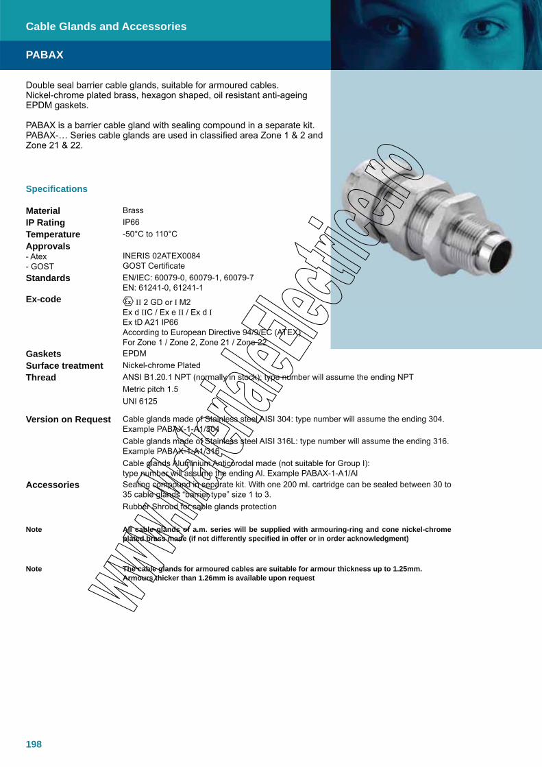
198
Double seal barrier cable glands, suitable for armoured cables.Nickel-chrome plated brass, hexagon shaped, oil resistant anti-ageing EPDM gaskets.
PABAX is a barrier cable gland with sealing compound in a separate kit. PABAX-… Series cable glands are used in classified area Zone 1 & 2 and Zone 21 & 22.
Specifications
Material BrassIP Rating IP66Temperature -50°C to 110°CApprovals- Atex- GOST
INERIS 02ATEX0084GOST Certificate
Standards EN/IEC: 60079-0, 60079-1, 60079-7EN: 61241-0, 61241-1
Ex-code II 2 GD or I M2Ex d IIC / Ex e II / Ex d IEx tD A21 IP66According to European Directive 94/9/EC (ATEX)For Zone 1 / Zone 2, Zone 21 / Zone 22
Gaskets EPDMSurface treatment Nickel-chrome PlatedThread ANSI B1.20.1 NPT (normally in stock): type number will assume the ending NPT
Metric pitch 1.5UNI 6125
Version on Request Cable glands made of Stainless steel AISI 304: type number will assume the ending 304. Example PABAX-1-A1/304Cable glands made of Stainless steel AISI 316L: type number will assume the ending 316. Example PABAX-1-A1/316Cable glands Aluminium Anticorodal made (not suitable for Group I): type number will assume the ending Al. Example PABAX-1-A1/Al
Accessories Sealing compound in separate kit. With one 200 ml. cartridge can be sealed between 30 to 35 cable glands “barrier type” size 1 to 3.Rubber Shroud for cable glands protection
Note All cable glands of a.m. series will be supplied with armouring-ring and cone nickel-chrome plated brass made (if not differently specified in offer or in order acknowledgment)
Note The cable glands for armoured cables are suitable for armour thickness up to 1.25mm. Armours thicker than 1.26mm is available upon request
PABAX
Cable Glands and Accessories
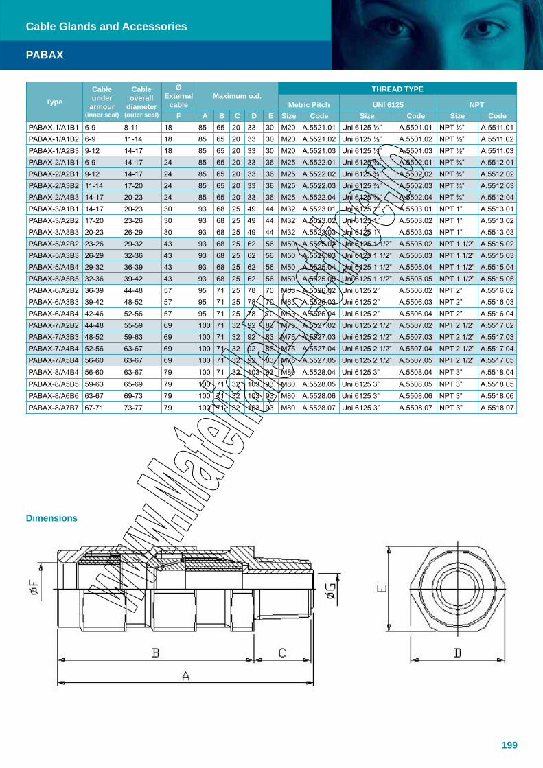
199
TypeCable under
armour(inner seal)
Cable overall
diameter(outer seal)
ØExternal
cableMaximum o.d.
THREAD TYPE
Metric Pitch UNI 6125 NPTF A B C D E Size Code Size Code Size Code
PABAX-1/A1B1 6-9 8-11 18 85 65 20 33 30 M20 A.5521.01 Uni 6125 ½” A.5501.01 NPT ½” A.5511.01PABAX-1/A1B2 6-9 11-14 18 85 65 20 33 30 M20 A.5521.02 Uni 6125 ½” A.5501.02 NPT ½” A.5511.02PABAX-1/A2B3 9-12 14-17 18 85 65 20 33 30 M20 A.5521.03 Uni 6125 ½” A.5501.03 NPT ½” A.5511.03PABAX-2/A1B1 6-9 14-17 24 85 65 20 33 36 M25 A.5522.01 Uni 6125 ¾” A.5502.01 NPT ¾” A.5512.01PABAX-2/A2B1 9-12 14-17 24 85 65 20 33 36 M25 A.5522.02 Uni 6125 ¾” A.5502.02 NPT ¾” A.5512.02PABAX-2/A3B2 11-14 17-20 24 85 65 20 33 36 M25 A.5522.03 Uni 6125 ¾” A.5502.03 NPT ¾” A.5512.03PABAX-2/A4B3 14-17 20-23 24 85 65 20 33 36 M25 A.5522.04 Uni 6125 ¾” A.5502.04 NPT ¾” A.5512.04PABAX-3/A1B1 14-17 20-23 30 93 68 25 49 44 M32 A.5523.01 Uni 6125 1” A.5503.01 NPT 1” A.5513.01PABAX-3/A2B2 17-20 23-26 30 93 68 25 49 44 M32 A.5523.02 Uni 6125 1” A.5503.02 NPT 1” A.5513.02PABAX-3/A3B3 20-23 26-29 30 93 68 25 49 44 M32 A.5523.03 Uni 6125 1” A.5503.03 NPT 1” A.5513.03PABAX-5/A2B2 23-26 29-32 43 93 68 25 62 56 M50 A.5525.02 Uni 6125 1 1/2” A.5505.02 NPT 1 1/2” A.5515.02PABAX-5/A3B3 26-29 32-36 43 93 68 25 62 56 M50 A.5525.03 Uni 6125 1 1/2” A.5505.03 NPT 1 1/2” A.5515.03PABAX-5/A4B4 29-32 36-39 43 93 68 25 62 56 M50 A.5525.04 Uni 6125 1 1/2” A.5505.04 NPT 1 1/2” A.5515.04PABAX-5/A5B5 32-36 39-42 43 93 68 25 62 56 M50 A.5525.05 Uni 6125 1 1/2” A.5505.05 NPT 1 1/2” A.5515.05PABAX-6/A2B2 36-39 44-48 57 95 71 25 78 70 M63 A.5526.02 Uni 6125 2” A.5506.02 NPT 2” A.5516.02PABAX-6/A3B3 39-42 48-52 57 95 71 25 78 70 M63 A.5526.03 Uni 6125 2” A.5506.03 NPT 2” A.5516.03PABAX-6/A4B4 42-46 52-56 57 95 71 25 78 70 M63 A.5526.04 Uni 6125 2” A.5506.04 NPT 2” A.5516.04PABAX-7/A2B2 44-48 55-59 69 100 71 32 92 83 M75 A.5527.02 Uni 6125 2 1/2” A.5507.02 NPT 2 1/2” A.5517.02PABAX-7/A3B3 48-52 59-63 69 100 71 32 92 83 M75 A.5527.03 Uni 6125 2 1/2” A.5507.03 NPT 2 1/2” A.5517.03PABAX-7/A4B4 52-56 63-67 69 100 71 32 92 83 M75 A.5527.04 Uni 6125 2 1/2” A.5507.04 NPT 2 1/2” A.5517.04PABAX-7/A5B4 56-60 63-67 69 100 71 32 92 83 M75 A.5527.05 Uni 6125 2 1/2” A.5507.05 NPT 2 1/2” A.5517.05PABAX-8/A4B4 56-60 63-67 79 100 71 32 103 93 M80 A.5528.04 Uni 6125 3” A.5508.04 NPT 3” A.5518.04PABAX-8/A5B5 59-63 65-69 79 100 71 32 103 93 M80 A.5528.05 Uni 6125 3” A.5508.05 NPT 3” A.5518.05PABAX-8/A6B6 63-67 69-73 79 100 71 32 103 93 M80 A.5528.06 Uni 6125 3” A.5508.06 NPT 3” A.5518.06PABAX-8/A7B7 67-71 73-77 79 100 71 32 103 93 M80 A.5528.07 Uni 6125 3” A.5508.07 NPT 3” A.5518.07
PABAX
Cable Glands and Accessories
Dimensions

200
Single seal barrier cable glands, suitable for unarmoured cables. Nickel-chrome plated brass, hexagon shaped, oil resistant anti-ageing EPDM gaskets.
PMS-… is a barrier cable gland with sealing compound in a separate kit. PMS-… Series cable glands are used in classified area Zone 1 & 2 and Zone 21 & 22.
Specifications
Material BrassIP Rating IP66Temperature -50°C to 110°CApprovals- Atex- GOST
INERIS 02ATEX0084GOST Certificate
Standards EN/IEC: 60079-0, 60079-1, 60079-7EN: 61241-0, 61241-1
Ex-code II 2 GD or I M2Ex d IIC / Ex e II / Ex d IEx tD A21 IP66According to European Directive 94/9/EC (ATEX)For Zone 1 / Zone 2, Zone 21 / Zone 22
Gaskets EPDMSurface treatment Nickel-chrome PlatedThread ANSI B1.20.1 NPT (normally in stock): type number will assume the ending NPT
Metric pitch 1.5UNI 6125
Version on Request Cable glands made of Stainless steel AISI 304: type number will assume the ending 304. Example PMS-1-A1/304Cable glands made of Stainless steel AISI 316L: type number will assume the ending 316. Example PMS-1-A1/316Cable glands Aluminium Anticorodal made (not suitable for Group I): type number will assume the ending Al. Example PMS-1-A1/Al
Accessories Sealing compound in separate kit. With one 200 ml. cartridge can be sealed between 30 to 35 cable glands “barrier type” size 1 to 3. Rubber Shroud for cable glands protection
PMS
Cable Glands and Accessories

201
PMS
Cable Glands and Accessories
Dimensions
TypeCable overall
diameter (outer seal)
ØExternal
cableMaximum o.d.
THREAD TYPE
Metric PitchUNI 6125 NPT
F A B C D E Size Code Size Code Thread type CodePMS-1/A1 6-9 18 62 42 20 33 30 M20 A.5421.01 UNI 6125 ½” A.5401.01 NPT 6125 ½” A.5411.01PMS-1/A2 9-12 18 62 42 20 33 30 M20 A.5421.02 UNI 6125 ½” A.5401.02 NPT 6125 ½” A.5411.02PMS-2/A1 6-9 24 62 42 20 40 36 M25 A.5422.01 UNI 6125 3/4” A.5402.01 NPT 6125 3/4” A.5412.01PMS-2/A2 9-12 24 62 42 20 40 36 M25 A.5422.02 UNI 6125 3/4” A.5402.02 NPT 6125 3/4” A.5412.02PMS-2/A3 11-14 24 62 42 20 40 36 M25 A.5422.03 UNI 6125 3/4” A.5402.03 NPT 6125 3/4” A.5412.03PMS-2/A4 14-17 24 62 42 20 40 36 M25 A.5422.04 UNI 6125 3/4” A.5402.04 NPT 6125 3/4” A.5412.04PMS-3/A1 14-17 30 70 45 25 49 44 M32 A.5423.01 UNI 6125 1” A.5403.01 NPT 6125 1” A.5413.01PMS-3/A2 17-20 30 70 45 25 49 44 M32 A.5423.02 UNI 6125 1” A.5403.02 NPT 6125 1” A.5413.02PMS-3/A3 20-23 30 70 45 25 49 44 M32 A.5423.03 UNI 6125 1” A.5403.03 NPT 6125 1” A.5413.03PMS-5/A2 23-26 43 70 45 25 62 56 M50 A.5425.02 UNI 6125 1 1/2” A.5405.02 NPT 6125 1 ½” A.5415.02PMS-5/A3 26-29 43 70 45 25 62 56 M50 A.5425.03 UNI 6125 1 1/2” A.5405.03 NPT 6125 1 ½” A.5415.03PMS-5/A4 29-32 43 70 45 25 62 56 M50 A.5425.04 UNI 6125 1 1/2” A.5405.04 NPT 6125 1 ½” A.5415.04PMS-5/A5 32-36 43 70 45 25 62 56 M50 A.5425.05 UNI 6125 1 1/2” A.5405.05 NPT 6125 1 ½” A.5415.05PMS-6/A2 36-39 57 72 46 25 78 70 M63 A.5426.02 UNI 6125 2” A.5406.02 NPT 6125 2” A.5416.02PMS-6/A3 39-42 57 72 46 25 78 70 M63 A.5426.03 UNI 6125 2” A.5406.03 NPT 6125 2” A.5416.03PMS-6/A4 42-46 57 72 46 25 78 70 M63 A.5426.04 UNI 6125 2” A.5406.04 NPT 6125 2” A.5416.04PMS-7/A2 44-48 69 78 46 25 78 70 M75 A.5427.02 UNI 6125 2 1/2” A.5407.02 NPT 6125 2 ½” A.5417.02PMS-7/A3 48-52 69 78 46 25 78 70 M75 A.5427.03 UNI 6125 2 1/2” A.5407.03 NPT 6125 2 ½” A.5417.03PMS-7/A4 52-56 69 78 46 25 78 70 M75 A.5427.04 UNI 6125 2 1/2” A.5407.04 NPT 6125 2 ½” A.5417.04PMS-7/A5 56-60 69 78 46 25 78 70 M75 A.5427.05 UNI 6125 2 1/2” A.5407.05 NPT 6125 2 ½” A.5417.05PMS-8/A4 56-60 79 78 46 32 103 93 M80 A.5428.04 UNI 6125 3” A.5408.04 NPT 6125 3” A.5418.04PMS-8/A5 59-63 79 78 46 32 103 93 M80 A.5428.05 UNI 6125 3” A.5408.05 NPT 6125 3” A.5418.05PMS-8/A6 63-67 79 78 46 32 103 93 M80 A.5428.06 UNI 6125 3” A.5408.06 NPT 6125 3” A.5418.06PMS-8/A7 67-71 79 78 46 32 103 93 M80 A.5428.07 UNI 6125 3” A.5408.07 NPT 6125 3” A.5418.07
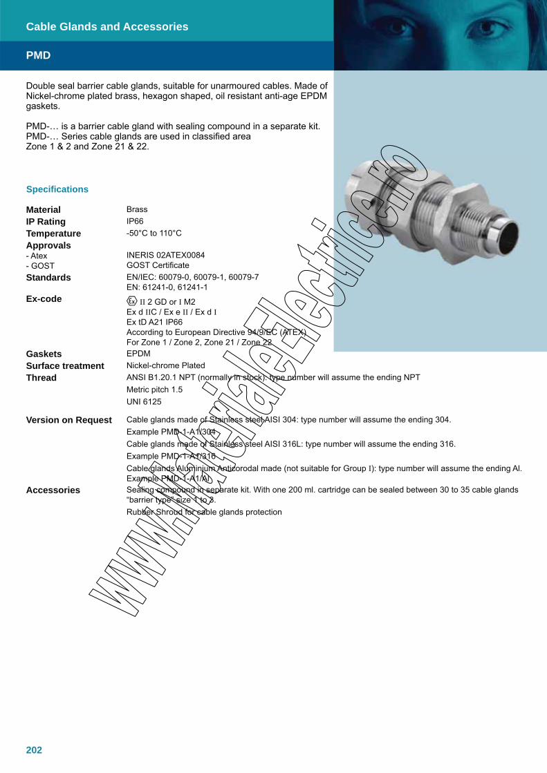
202
Double seal barrier cable glands, suitable for unarmoured cables. Made of Nickel-chrome plated brass, hexagon shaped, oil resistant anti-age EPDM gaskets.
PMD-… is a barrier cable gland with sealing compound in a separate kit. PMD-… Series cable glands are used in classified area Zone 1 & 2 and Zone 21 & 22.
Specifications
Material BrassIP Rating IP66Temperature -50°C to 110°CApprovals- Atex- GOST
INERIS 02ATEX0084GOST Certificate
Standards EN/IEC: 60079-0, 60079-1, 60079-7EN: 61241-0, 61241-1
Ex-code II 2 GD or I M2Ex d IIC / Ex e II / Ex d IEx tD A21 IP66According to European Directive 94/9/EC (ATEX)For Zone 1 / Zone 2, Zone 21 / Zone 22
Gaskets EPDMSurface treatment Nickel-chrome PlatedThread ANSI B1.20.1 NPT (normally in stock): type number will assume the ending NPT
Metric pitch 1.5UNI 6125
Version on Request Cable glands made of Stainless steel AISI 304: type number will assume the ending 304. Example PMD-1-A1/304Cable glands made of Stainless steel AISI 316L: type number will assume the ending 316. Example PMD-1-A1/316Cable glands Aluminium Anticorodal made (not suitable for Group I): type number will assume the ending Al. Example PMD-1-A1/Al
Accessories Sealing compound in separate kit. With one 200 ml. cartridge can be sealed between 30 to 35 cable glands “barrier type” size 1 to 3.Rubber Shroud for cable glands protection
PMD
Cable Glands and Accessories

203
PMD
Cable Glands and Accessories
TypeCable overall
diameter(2nd insulation)
Cable overall
diameter(1st insulation)
ØExternal
cableMaximum o.d.
THREAD TYPE
Metric Pitch UNI 6125NPT
F A B C D E Size Code Size Code Size CodePMD-1/A1B1 6-9 8-11 18 85 65 20 33 30 M20 A.5621.01 Uni 6125 ½” A.5601.01 NPT ½” A.5611.01
PMD-1/A1B2 6-9 11-14 18 85 65 20 33 30 M20 A.5621.02 Uni 6125 ½” A.5601.02 NPT ½” A.5611.02
PMD-1/A2B3 9-12 14-17 18 85 65 20 33 30 M20 A.5621.03 Uni 6125 ½” A.5601.03 NPT ½” A.5611.03
PMD-2/A1B1 6-9 14-17 24 85 65 20 33 36 M25 A.5622.01 Uni 6125 ¾” A.5602.01 NPT ¾” A.5612.01
PMD-2/A2B1 9-12 14-17 24 85 65 20 33 36 M25 A.5622.02 Uni 6125 ¾” A.5602.02 NPT ¾” A.5612.02
PMD-2/A3B2 11-14 17-20 24 85 65 20 33 36 M25 A.5622.03 Uni 6125 ¾” A.5602.03 NPT ¾” A.5612.03
PMD-2/A4B3 14-17 20-23 24 85 65 20 33 36 M25 A.5622.04 Uni 6125 ¾” A.5602.04 NPT ¾” A.5612.04PMD-3/A1B1 14-17 20-23 30 93 68 25 49 44 M32 A.5623.01 Uni 6125 1” A.5603.01 NPT 1” A.5613.01PMD-3/A2B2 17-20 23-26 30 93 68 25 49 44 M32 A.5623.02 Uni 6125 1” A.5603.02 NPT 1” A.5613.02PMD-3/A3B3 20-23 26-29 30 93 68 25 49 44 M32 A.5623.03 Uni 6125 1” A.5603.03 NPT 1” A.5613.03PMD-5/A2B2 23-26 29-32 43 93 68 25 62 56 M50 A.5625.02 Uni 6125 1 1/2” A.5605.02 NPT 1 1/2” A.5615.02PMD-5/A3B3 26-29 32-36 43 93 68 25 62 56 M50 A.5625.03 Uni 6125 1 1/2” A.5605.03 NPT 1 1/2” A.5615.03PMD-5/A4B4 29-32 36-39 43 93 68 25 62 56 M50 A.5625.04 Uni 6125 1 1/2” A.5605.04 NPT 1 1/2” A.5615.04PMD-5/A5B5 32-36 39-42 43 93 68 25 62 56 M50 A.5625.05 Uni 6125 1 1/2” A.5605.05 NPT 1 1/2” A.5615.05PMD-6/A2B2 36-39 44-48 57 95 71 25 78 70 M63 A.5626.02 Uni 6125 2” A.5606.02 NPT 2” A.5616.02PMD-6/A3B3 39-42 48-52 57 95 71 25 78 70 M63 A.5626.03 Uni 6125 2” A.5606.03 NPT 2” A.5616.03PMD-6/A4B4 42-46 52-56 57 95 71 25 78 70 M63 A.5626.04 Uni 6125 2” A.5606.04 NPT 2” A.5616.04PMD-7/A2B2 44-48 55-59 69 100 71 32 92 83 M75 A.5627.02 Uni 6125 2 1/2” A.5607.02 NPT 2 1/2” A.5617.02PMD-7/A3B3 48-52 59-63 69 100 71 32 92 83 M75 A.5627.03 Uni 6125 2 1/2” A.5607.03 NPT 2 1/2” A.5617.03PMD-7/A4B4 52-56 63-67 69 100 71 32 92 83 M75 A.5627.04 Uni 6125 2 1/2” A.5607.04 NPT 2 1/2” A.5617.04PMD-7/A5B4 56-60 63-67 69 100 71 32 92 83 M75 A.5627.05 Uni 6125 2 1/2” A.5607.05 NPT 2 1/2” A.5617.05PMD-8/A4B4 56-60 63-67 79 100 71 32 103 93 M80 A.5628.04 Uni 6125 3” A.5608.04 NPT 3” A.5618.04PMD-8/A5B5 59-63 65-69 79 100 71 32 103 93 M80 A.5628.05 Uni 6125 3” A.5608.05 NPT 3” A.5618.05PMD-8/A6B6 63-67 69-73 79 100 71 32 103 93 M80 A.5628.06 Uni 6125 3” A.5608.06 NPT 3” A.5618.06PMD-8/A7B7 67-71 73-77 79 100 71 32 103 93 M80 A.5628.07 Uni 6125 3” A.5608.07 NPT 3” A.5618.07
Dimensions

204

205
Specifications
Material Galvanised steelThread RE... Series:
Larger External Male Thread NPT/Smaller Inner Female Thread NPT
Larger External Male Thread UNI 6125/Smaller Inner Female Thread UNI 6125
Version on Request Alternative materials are:- Brass nickel chrome-plating finishing- Stainless Steel- Aluminium (Mg. ≤ 6%). Not suitable for Group I
Note The Marking is directly realized on the reducers with mechanically incision inscriptions
Reducers provide a means of connection between equipment with dissimilar thread sizes.
RE range of reducers: Larger External Male Thread/Smaller Inner Female Thread
All the Reducers are designed for Ex d and Ex e mode of protection. Different types and sizes are indicated on the “Reducer Selection Table”
Fitting Accessories
Cable Glands and Accessories
Selection Table
Code UNI 6125 Code NPT Type Size Weight (kg)A.0050.01 A.0050.61 RE 21 3/4” X 1/2” 0.04
A.0050.02 A.0050.62 RE 31 1” X 1/2” 0.08
A.0050.03 A.0050.63 RE 32 1” X 3/4” 0.08
A.0050.07 A.0050.67 RE 51 1 ½” X 1/2” 0.27
A.0050.08 A.0050.68 RE 52 1 ½” X 3/4” 0.27
A.0050.09 A.0050.69 RE 53 1 ½” X 1” 0.27
A.0050.12 A.0050.72 RE 62 2” X 3/4” 0.48
A.0050.13 A.0050.73 RE 63 2” X 1” 0.48
A.0050.15 A.0050.75 RE 65 2” X 1 ½” 0.48
A.0050.17 RE 72 2 ½” X 3/4” 0.80
A.0050.18 A.0050.78 RE 73 2 ½” X 1” 0.80
A.0050.20 A.0050.80 RE 75 2 ½” X 1 ½” 0.80
A.0050.21 A.0050.81 RE 76 2 ½” X 2” 0.80
A.0050.23 RE 82 3” X 3/4” 1.00
A.0050.24 A.0050.84 RE 83 3” X 1” 1.00
A.0050.26 A.0050.86 RE 85 3” X 1 ½” 1.00
A.0050.27 A.0050.87 RE 86 3” X 2” 1.00
A.0050.28 A.0050.88 RE 87 3” X 2 ½” 1.00
Reducers ordering examples: E.g. Type RE31 = Male Thread 1” / Famale Thread ½”
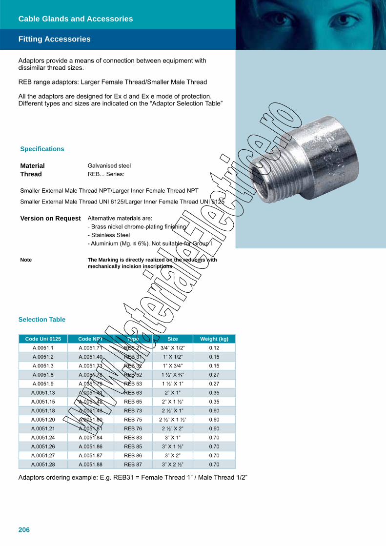
206
Fitting Accessories
Cable Glands and Accessories
Code Uni 6125 Code NPT Type Size Weight (kg)A.0051.1 A.0051.71 REB 21 3/4” X 1/2” 0.12
A.0051.2 A.0051.40 REB 31 1” X 1/2” 0.15
A.0051.3 A.0051.73 REB 32 1” X 3/4” 0.15
A.0051.8 A.0051.78 REB 52 1 ½” X ¾” 0.27
A.0051.9 A.0051.79 REB 53 1 ½” X 1” 0.27
A.0051.13 A.0051.41 REB 63 2” X 1” 0.35
A.0051.15 A.0051.42 REB 65 2” X 1 ½” 0.35
A.0051.18 A.0051.43 REB 73 2 ½” X 1” 0.60
A.0051.20 A.0051.80 REB 75 2 ½” X 1 ½” 0.60
A.0051.21 A.0051.81 REB 76 2 ½” X 2” 0.60
A.0051.24 A.0051.84 REB 83 3” X 1” 0.70
A.0051.26 A.0051.86 REB 85 3” X 1 ½” 0.70
A.0051.27 A.0051.87 REB 86 3” X 2” 0.70
A.0051.28 A.0051.88 REB 87 3” X 2 ½” 0.70
Specifications
Material Galvanised steelThread REB... Series:
Smaller External Male Thread NPT/Larger Inner Female Thread NPT
Smaller External Male Thread UNI 6125/Larger Inner Female Thread UNI 6125
Version on Request Alternative materials are:- Brass nickel chrome-plating finishing- Stainless Steel- Aluminium (Mg. ≤ 6%). Not suitable for Group I
Note The Marking is directly realized on the reducers with mechanically incision inscriptions
Adaptors provide a means of connection between equipment with dissimilar thread sizes.
REB range adaptors: Larger Female Thread/Smaller Male Thread
All the adaptors are designed for Ex d and Ex e mode of protection. Different types and sizes are indicated on the “Adaptor Selection Table”
Selection Table
Adaptors ordering example: E.g. REB31 = Female Thread 1” / Male Thread 1/2”

207
Fitting Accessories
Cylindrical Male PG / Conic Female UNI-6125 or NPT threadCODE UNI 6125 CODE NPT TYPE SIZE WEIGHT (Kg)A.0051.52 A.0052.60 REB 16/1 ½” X PG 16 0.12A.0051.50 A.0052.61 REB 16/2 ¾” X PG 16 0.15A.0051.53 A.0052.62 REB 21/2 ¾” X PG 21 0.27A.0051.51 A.0052.63 REB 21/3 1” X PG 21 0.27A.0051.54 A.0052.64 REB 29/3 1” X PG 29 0.30A.0051.55 A.0052.65 REB 36/5 1 ½” X PG 36 0.35A.0051.56 A.0052.66 REB 42/6 2” X PG 42 0.60A.0051.57 A.0052.67 REB 48/6 2” X PG 48 0.70
Cylindrical Male Metric Pitch (1,5) / Conic Female UNI-6125CODE UNI 6125 Type TYPE WEIGHT (kg)A.0051.61 REB m16/1 M 16 X 1/2” 0.12A.0051.62 REB m20/1 M 20 X 1/2” 0.15A.0051.63 REB m20/2 M 20 X 3/4” 0.27A.0051.64 REB m25/2 M 25 X 3/4” 0.27A.0051.65 REB m25/3 M 25 X 1” 0.30A.0051.66 REB m32/3 M 32 X 1” 0.35
Cable Glands and Accessories
Specifications
Material Brass nickel chrome-plating finishing
Version on Request Alternative materials are:- Stainless Steel- Aluminium (Mg. ≤ 6%). Not suitable for Group I- Galvanized mild Steel
Note The Marking is directly realized on the adaptors with mechanically incision inscriptions
Male Taper NPT / Female Taper UNI 6125 thread adaptors provide a connection between equipment with dissimilar thread sizes and type.
All the adaptors are designed for Ex d and Ex e mode of protection. Different types and sizes are indicated on the “Adaptor Selection Table”
Selection Tables
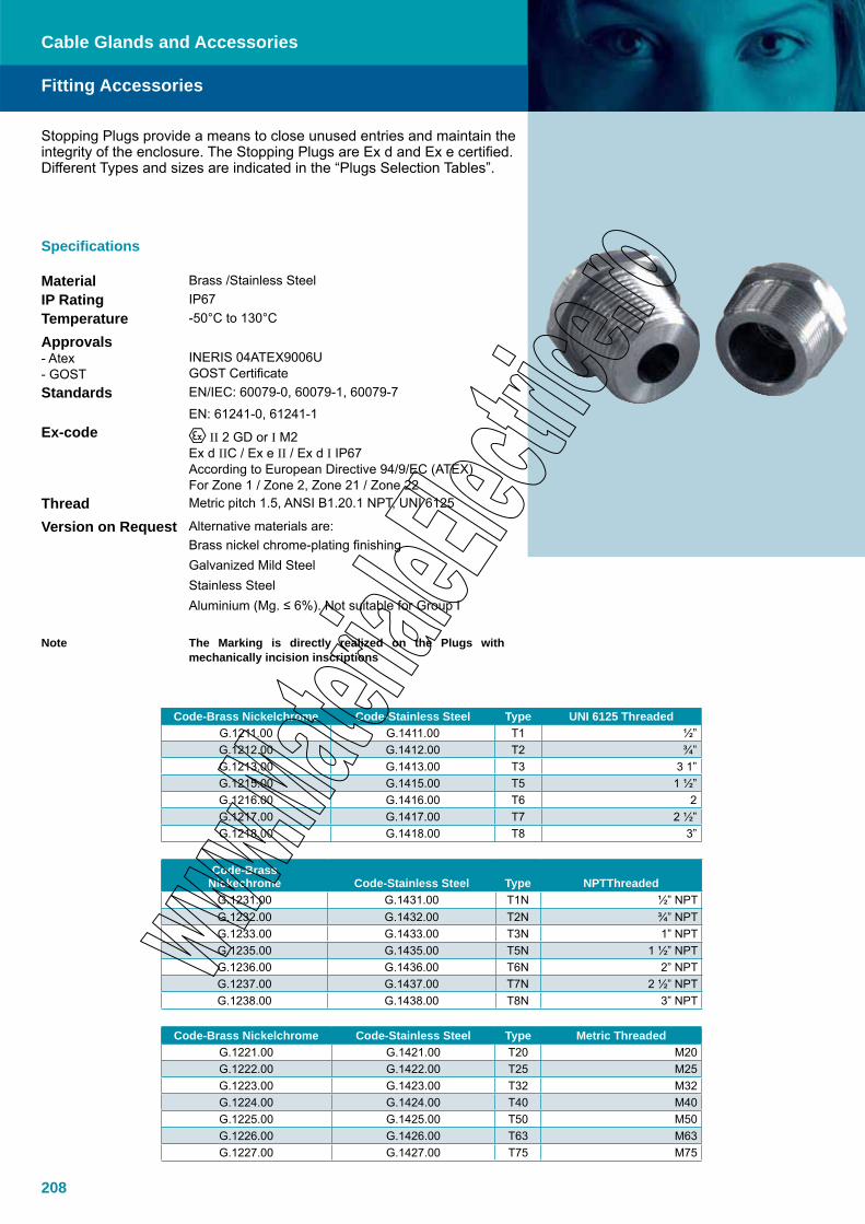
208
Fitting Accessories
Stopping Plugs provide a means to close unused entries and maintain the integrity of the enclosure. The Stopping Plugs are Ex d and Ex e certified. Different Types and sizes are indicated in the “Plugs Selection Tables”.
Code-Brass Nickelchrome Code-Stainless Steel Type UNI 6125 ThreadedG.1211.00 G.1411.00 T1 ½”G.1212.00 G.1412.00 T2 ¾”G.1213.00 G.1413.00 T3 3 1”G.1215.00 G.1415.00 T5 1 ½”G.1216.00 G.1416.00 T6 2G.1217.00 G.1417.00 T7 2 ½”G.1218.00 G.1418.00 T8 3”
Code-Brass Nickechrome Code-Stainless Steel Type NPTThreaded
G.1231.00 G.1431.00 T1N ½” NPTG.1232.00 G.1432.00 T2N ¾” NPTG.1233.00 G.1433.00 T3N 1” NPTG.1235.00 G.1435.00 T5N 1 ½” NPTG.1236.00 G.1436.00 T6N 2” NPTG.1237.00 G.1437.00 T7N 2 ½” NPTG.1238.00 G.1438.00 T8N 3” NPT
Code-Brass Nickelchrome Code-Stainless Steel Type Metric ThreadedG.1221.00 G.1421.00 T20 M20G.1222.00 G.1422.00 T25 M25G.1223.00 G.1423.00 T32 M32G.1224.00 G.1424.00 T40 M40G.1225.00 G.1425.00 T50 M50G.1226.00 G.1426.00 T63 M63G.1227.00 G.1427.00 T75 M75
Specifications
Material Brass /Stainless SteelIP Rating IP67Temperature -50°C to 130°C
Approvals- Atex- GOST
INERIS 04ATEX9006UGOST Certificate
Standards EN/IEC: 60079-0, 60079-1, 60079-7
EN: 61241-0, 61241-1Ex-code II 2 GD or I M2
Ex d IIC / Ex e II / Ex d I IP67According to European Directive 94/9/EC (ATEX)For Zone 1 / Zone 2, Zone 21 / Zone 22
Thread Metric pitch 1.5, ANSI B1.20.1 NPT, UNI 6125
Version on Request Alternative materials are:Brass nickel chrome-plating finishingGalvanized Mild SteelStainless SteelAluminium (Mg. ≤ 6%). Not suitable for Group I
Note The Marking is directly realized on the Plugs with mechanically incision inscriptions
Cable Glands and Accessories
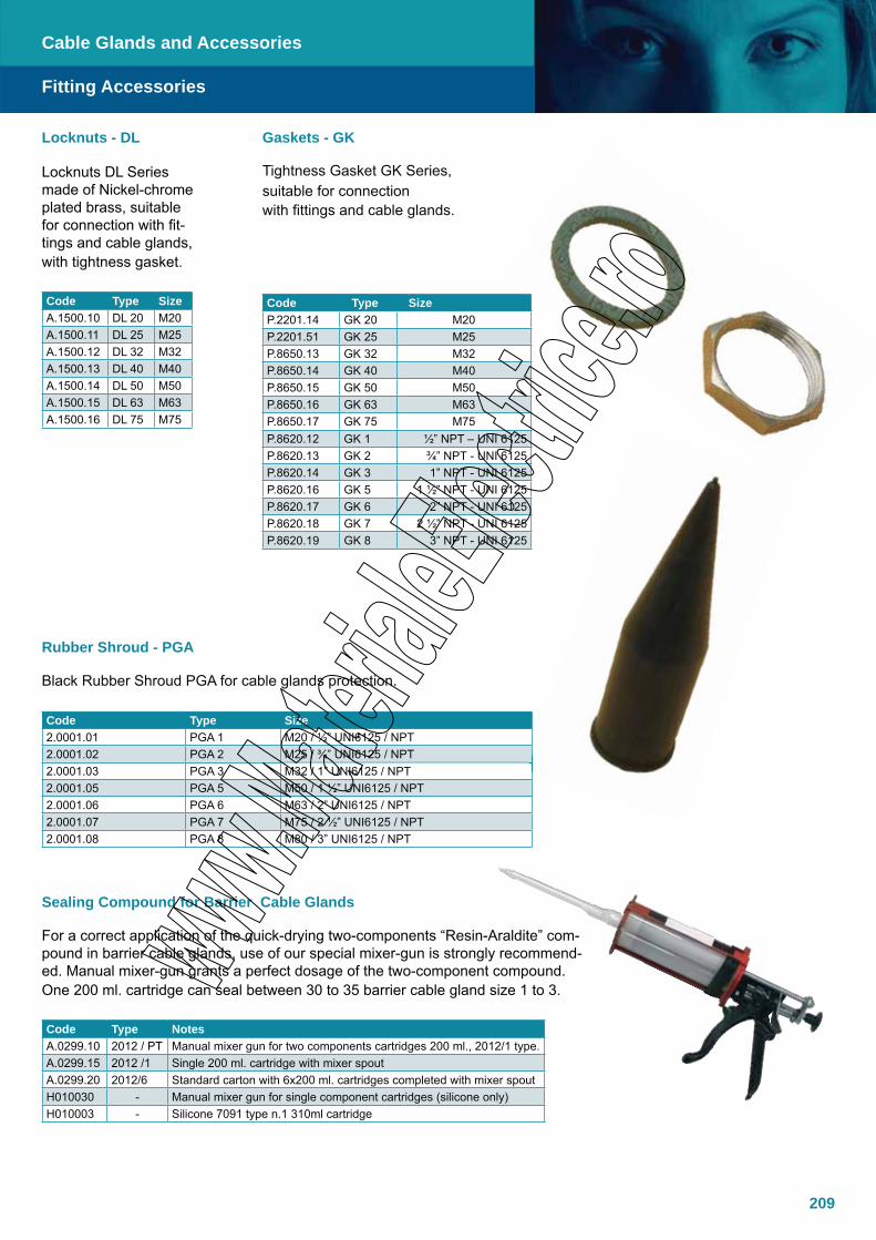
209
Locknuts DL Series made of Nickel-chrome plated brass, suitable for connection with fit-tings and cable glands,with tightness gasket.
Code Type SizeA.1500.10 DL 20 M20A.1500.11 DL 25 M25A.1500.12 DL 32 M32A.1500.13 DL 40 M40A.1500.14 DL 50 M50A.1500.15 DL 63 M63A.1500.16 DL 75 M75
Fitting Accessories
Tightness Gasket GK Series, suitable for connection with fittings and cable glands.
Code Type SizeP.2201.14 GK 20 M20P.2201.51 GK 25 M25P.8650.13 GK 32 M32P.8650.14 GK 40 M40P.8650.15 GK 50 M50P.8650.16 GK 63 M63P.8650.17 GK 75 M75P.8620.12 GK 1 ½” NPT – UNI 6125P.8620.13 GK 2 ¾” NPT - UNI 6125P.8620.14 GK 3 1” NPT - UNI 6125P.8620.16 GK 5 1 ½” NPT - UNI 6125P.8620.17 GK 6 2” NPT - UNI 6125P.8620.18 GK 7 2 ½” NPT - UNI 6125P.8620.19 GK 8 3” NPT - UNI 6125
Locknuts - DL Gaskets - GK
Cable Glands and Accessories
Black Rubber Shroud PGA for cable glands protection.
Code Type Size2.0001.01 PGA 1 M20 / ½” UNI6125 / NPT2.0001.02 PGA 2 M25 / ¾” UNI6125 / NPT 2.0001.03 PGA 3 M32 / 1” UNI6125 / NPT2.0001.05 PGA 5 M50 / 1 ½” UNI6125 / NPT2.0001.06 PGA 6 M63 / 2” UNI6125 / NPT2.0001.07 PGA 7 M75 / 2 ½” UNI6125 / NPT2.0001.08 PGA 8 M80 / 3” UNI6125 / NPT
For a correct application of the quick-drying two-components “Resin-Araldite” com-pound in barrier cable glands, use of our special mixer-gun is strongly recommend-ed. Manual mixer-gun grants a perfect dosage of the two-component compound. One 200 ml. cartridge can seal between 30 to 35 barrier cable gland size 1 to 3.
Code Type NotesA.0299.10 2012 / PT Manual mixer gun for two components cartridges 200 ml., 2012/1 type.A.0299.15 2012 /1 Single 200 ml. cartridge with mixer spoutA.0299.20 2012/6 Standard carton with 6x200 ml. cartridges completed with mixer spoutH010030 - Manual mixer gun for single component cartridges (silicone only)H010003 - Silicone 7091 type n.1 310ml cartridge
Rubber Shroud - PGA
Sealing Compound for Barrier Cable Glands
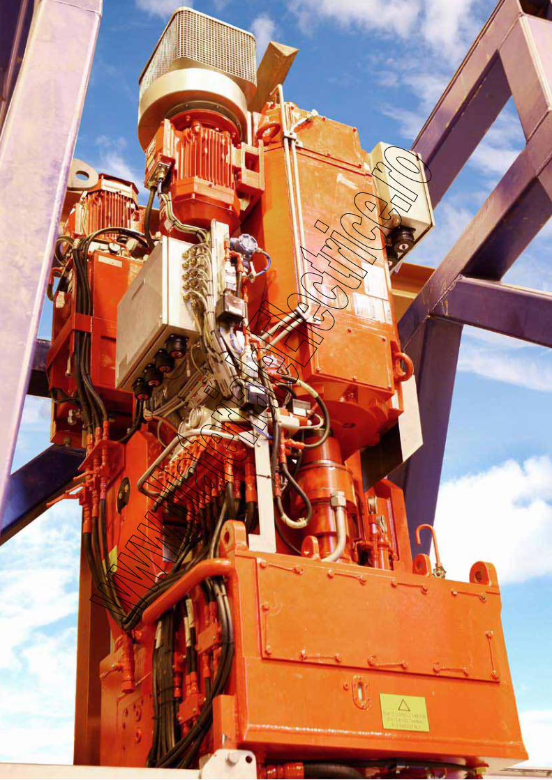
210
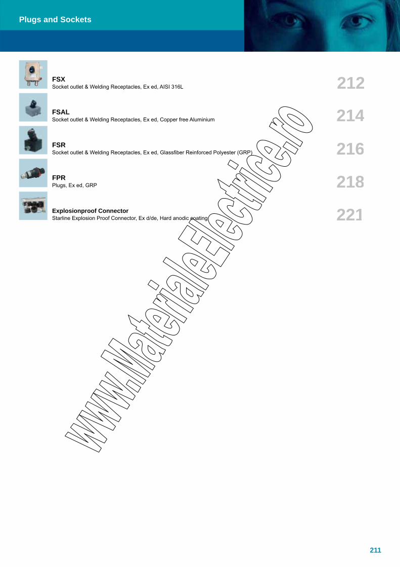
211
Plugs and Sockets
FSXSocket outlet & Welding Receptacles, Ex ed, AISI 316L
FSALSocket outlet & Welding Receptacles, Ex ed, Copper free Aluminium
FPR Plugs, Ex ed, GRP
Explosionproof ConnectorStarline Explosion Proof Connector, Ex d/de, Hard anodic coating
FSRSocket outlet & Welding Receptacles, Ex ed, Glassfiber Reinforced Polyester (GRP)
212
214
216
218
221
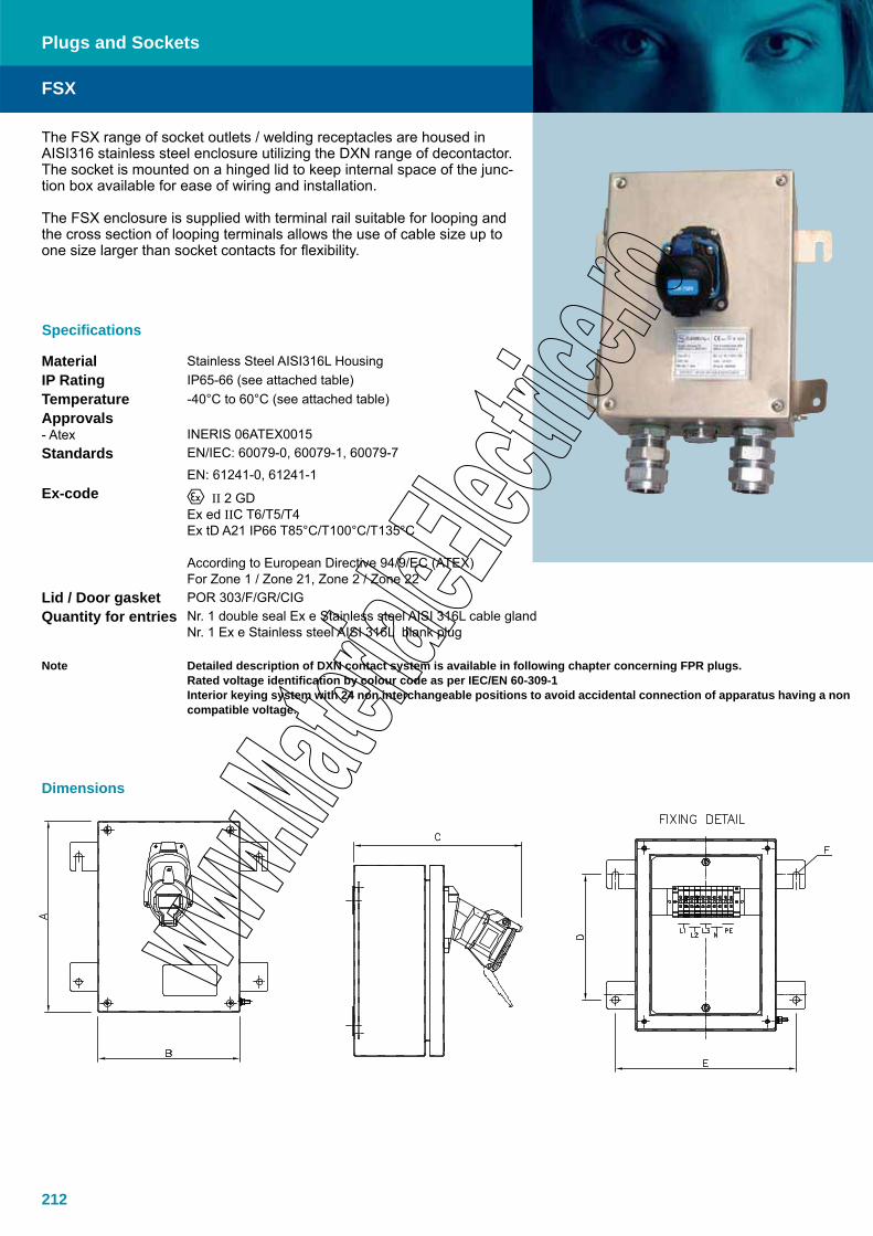
212
The FSX range of socket outlets / welding receptacles are housed in AISI316 stainless steel enclosure utilizing the DXN range of decontactor. The socket is mounted on a hinged lid to keep internal space of the junc-tion box available for ease of wiring and installation.
The FSX enclosure is supplied with terminal rail suitable for looping and the cross section of looping terminals allows the use of cable size up to one size larger than socket contacts for flexibility.
Specifications
Material Stainless Steel AISI316L HousingIP Rating IP65-66 (see attached table)Temperature -40°C to 60°C (see attached table)Approvals- Atex
INERIS 06ATEX0015
Standards EN/IEC: 60079-0, 60079-1, 60079-7
EN: 61241-0, 61241-1Ex-code II 2 GD
Ex ed IIC T6/T5/T4Ex tD A21 IP66 T85°C/T100°C/T135°C
According to European Directive 94/9/EC (ATEX)For Zone 1 / Zone 21, Zone 2 / Zone 22
Lid / Door gasket POR 303/F/GR/CIGQuantity for entries Nr. 1 double seal Ex e Stainless steel AISI 316L cable gland
Nr. 1 Ex e Stainless steel AISI 316L blank plug
Note Detailed description of DXN contact system is available in following chapter concerning FPR plugs. Rated voltage identification by colour code as per IEC/EN 60-309-1Interior keying system with 24 non interchangeable positions to avoid accidental connection of apparatus having a non compatible voltage.
FSX
Plugs and Sockets
Dimensions

213
ITEM TYPEITEM CODE
COLOR CODE
VOLTAGE [V]
CON-TACT ARR-
ANGE-MENTS
CURRENT [A]
Earth Pin Position
FQ[Hz]
CON-NECTIONTERMINALS
CROSSSECTIONFLEXIBLE
CORES(RIGID
CORES)[mmq] ENTRIES
OVERALL DIMENSIONS (AxBxC) [mm]
MOUNTING INTERAXES
(ExD)-F
FSX-2-20-24-50 A.4300.26 24 2P 20 Central 50 10 / 10 2 x M25 217X200X257 192X1 -9FSX-3-20-110-50 A.4300.27 110-130 1P+N+E 20 Central 50 10 / 10 2 x M25 217X200X257 192X1 -9FSX-3-20-230-50 A.4300.28 220-250 1P+N+E 20 Central 50 10 / 10 2 x M25 217X200X257 192X1 -9FSX-4-20-400-50 A.4300.29 380-440 3P+E 20 Central 50 10 / 10 2 x M25 280X270X257 255X177 -9FSX-5-20-400-50 A.4300.30 380-440 3P+N+E 20 Central 50 10 / 10 2 x M25 280X270X257 255X177 -9
FSX-2-32-24-50 A.4300.31 24 2P 32 Central 50 16 / 16 2 x M32 280X270X268 255X177 -9FSX-3-32-110-50 A.4300.32 110-130 1P+N+E 32 Central 50 16 / 16 2 x M32 280X270X268 255X177 -9FSX-3-32-230-50 A.4300.33 220-250 1P+N+E 32 Central 50 16 / 16 2 x M32 280X270X268 255X177 -9FSX-4-32-400-50 A.4300.34 380-440 3P+E 32 Central 50 16 / 16 2 x M32 350X350X268 325X257 -9FSX-5-32-400-50 A.4300.35 380-440 3P+N+E 32 Central 50 16 / 16 2 x M32 350X350X268 325X257 -9
FSX-2-63-24-50 A.4300.36 24 2P 63 Central 50 35 / 35 2 x M50 350X350X295 325X257 -9FSX-3-63-110-50 A.4300.37 110-130 1P+N+E 63 Central 50 35 / 35 2 x M50 350X350X295 325X257 -9FSX-3-63-230-50 A.4300.38 220-250 1P+N+E 63 Central 50 35 / 35 2 x M50 350X350X295 325X257 -9FSX-4-63-400-50 A.4300.39 380-440 3P+E 63 Central 50 35 / 35 2 x M50 430X500X325 405X407 -9FSX-5-63-400-50 A.4300.40 380-440 3P+N+E 63 Central 50 35 / 35 2 x M50 430X500X325 405X407 -9
ITEM TYPE
ITEM CODE
COLOR CODE
VOLTAGE (V)
CONTACT ARRANGE-
MENTSCURRENT
(A)
Earth Pin
Position
FRE-QUENCY
(HZ)
CONNECTIONTERMINALS
CROSSSECTIONFLEXIBLE
CORES(RIGID
CORES)mmq ENTRIES
OVERALL DIMEN-SIONS
(AxBxC)
MOUN-TING
INTER-AXES
(ExD)-F
FSX-2-2a-32-24-50 A.4300.80 242P+2aux 32 Central 50 16 / 16 /4
2 x M25+ 1 x M20
280x270x268 255x177-9
FSX-3-2a-32-110-50 A.4300.41 110-1301P+N+E+2aux 32 Central 50 16 / 16 /4
2 x M25+ 1 x M20
280x270x268 255x177-9
FSX-3-2a-32-230-50 A.4300.42 220-2501P+N+E+2aux 32 Central 50 16 / 16 /4
2 x M25+ 1 x M20
280x270x268 255x177-9
FSX-4-2a-32-400-50 A.4300.43 380-4403P+E+2aux 32 Central 50 16 / 16 /4
2 x M32+ 1 x M20
350x350x268 325x257-9
FSX-5-2a-32-400-50 A.4300.44 380-4403P+N+E+2aux 32 Central 50 16 / 16 /4
2 x M32+ 1 x M20
350x350x268 325x257-9
FSX-2-2a-63-24-50 A.4300.45 242P+2aux 63 Central 50 35 / 35 / 4
2 x M32+ 1 x M20
350x350x295 325x257-9
FSX-3-2a-63-110-50 A.4300.46 110-1301P+N+E+2aux 63 Central 50 35 / 35 / 4
2 x M32+ 1 x M20
350x350x295 325x257-9
FSX-3-2a-63-230-50 A.4300.47 220-2501P+N+E+2aux 63 Central 50 35 / 35 / 4
2 x M32+ 1 x M20
350x350x295 325x257-9
FSX-4-2a-63-400-50 A.4300.48 380-4403P+E+2aux 63 Central 50 35 / 35 / 4
2 x M50+ 1 x M20
350x350x295 325x257-9
FSX-5-2a-63-400-50 A.4300.49 380-4403P+N+E+2aux 63 Central 50 35 / 35 / 4
2 x M50+ 1 x M20
350x350x295 325x257-9
I.E. / Example FSX-3-2a-32-230-50 FSX = Flameproof Socket Stainless Steel 3 = Poles Number 2a = Number auxiliary contact
20 = Current (A) 230 = Voltage (V) 50 = Frequency (HZ)
I.E. / Example FSX-3-20-230-50 FSX = Flameproof Socket Stainless Steel3 = Poles Number
20 = Current (A)230 = Voltage (V)50 = Frequency (HZ)
FSX
Plugs and Sockets

214
The FSAL range of socket outlets / welding receptacles are housed in a copper free aluminium enclosure utilizing the DXN range of decontactor. The socket is mounted on a hinged lid to keep internal space of the junction box available for ease of wiring and installation. The FSAL enclosure is supplied with terminal rail suitable for looping and the cross section of looping terminals allows the use of cable size up to one size larger than socket contacts for flexibility.
Specifications
Material Copper Free Aluminum HousingIP Rating IP65-66 (see attached table)Temperature -40°C to 60°C (see attached table)Approvals- Atex
INERIS 06ATEX0015
Standards EN/IEC: 60079-0, 60079-1, 60079-7
EN: 61241-0, 61241-1Ex-code II 2 GD
Ex ed IIC T6/T5/T4Ex tD A21 IP66 T85°C/T100°C/T135°CAccording to European Directive 94/9/EC (ATEX)For Zone 1 / Zone 21, Zone 2 / Zone 22
Lid / Door gasket Silicone sealSurface treatment External polyurethane painting (RAL 6003)vQuantity for entries Nr. 1 single seal Ex e brass nickel chrome plated cable gland for armoured cable
Nr. 1 Ex e brass nickel chrome plated blank plug
Note Detailed description of DXN contact system is available in following chapter concerning FPR plugs. Rated voltage identification by colour code as per IEC/EN 60-309-1Interior keying system with 24 non interchangeable positions to avoid accidental connection of apparatus having a non compatible voltage.
FSAL
Plugs and Sockets
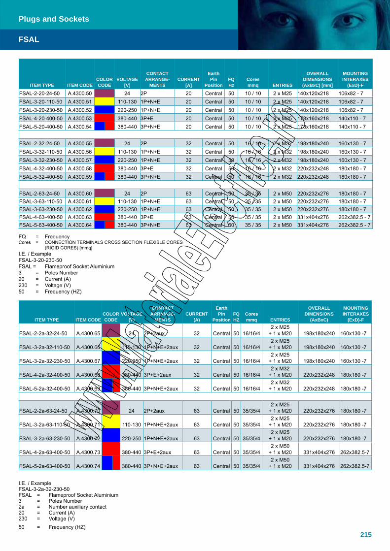
215
ITEM TYPE ITEM CODECOLOR CODE
VOLTAGE[V]
CONTACT ARRANGE-
MENTSCURRENT
[A]
EarthPin
Position FQHz
Coresmmq ENTRIES
OVERALL DIMENSIONS (AxBxC) [mm]
MOUNTING INTERAXES
(ExD)-F
FSAL-2-20-24-50 A.4300.50 24 2P 20 Central 50 10 / 10 2 x M25 140x120x218 106x82 - 7FSAL-3-20-110-50 A.4300.51 110-130 1P+N+E 20 Central 50 10 / 10 2 x M25 140x120x218 106x82 - 7FSAL-3-20-230-50 A.4300.52 220-250 1P+N+E 20 Central 50 10 / 10 2 x M25 140x120x218 106x82 - 7FSAL-4-20-400-50 A.4300.53 380-440 3P+E 20 Central 50 10 / 10 2 x M25 178x160x218 140x110 - 7FSAL-5-20-400-50 A.4300.54 380-440 3P+N+E 20 Central 50 10 / 10 2 x M25 178x160x218 140x110 - 7
FSAL-2-32-24-50 A.4300.55 24 2P 32 Central 50 16 / 16 2 x M32 198x180x240 160x130 - 7FSAL-3-32-110-50 A.4300.56 110-130 1P+N+E 32 Central 50 16 / 16 2 x M32 198x180x240 160x130 - 7FSAL-3-32-230-50 A.4300.57 220-250 1P+N+E 32 Central 50 16 / 16 2 x M32 198x180x240 160x130 - 7FSAL-4-32-400-50 A.4300.58 380-440 3P+E 32 Central 50 16 / 16 2 x M32 220x232x248 180x180 - 7FSAL-5-32-400-50 A.4300.59 380-440 3P+N+E 32 Central 50 16 / 16 2 x M32 220x232x248 180x180 - 7
FSAL-2-63-24-50 A.4300.60 24 2P 63 Central 50 35 / 35 2 x M50 220x232x276 180x180 - 7FSAL-3-63-110-50 A.4300.61 110-130 1P+N+E 63 Central 50 35 / 35 2 x M50 220x232x276 180x180 - 7FSAL-3-63-230-50 A.4300.62 220-250 1P+N+E 63 Central 50 35 / 35 2 x M50 220x232x276 180x180 - 7FSAL-4-63-400-50 A.4300.63 380-440 3P+E 63 Central 50 35 / 35 2 x M50 331x404x276 262x382.5 - 7FSAL-5-63-400-50 A.4300.64 380-440 3P+N+E 63 Central 50 35 / 35 2 x M50 331x404x276 262x382.5 - 7
FQ = FrequencyCores = CONNECTION TERMINALS CROSS SECTION FLEXIBLE CORES (RIGID CORES) [mmq]I.E. / Example FSAL-3-20-230-50 FSAL = Flameproof Socket Aluminium3 = Poles Number20 = Current (A)230 = Voltage (V)50 = Frequency (HZ)
ITEM TYPE ITEM CODECOLOR CODE
VOLTAGE (V)
CONTACT ARRANGE-
MENTSCURRENT
(A)
Earth Pin
Position FQHZ
Coresmmq ENTRIES
OVERALL DIMENSIONS
(AxBxC)
MOUNTING INTERAXES
(ExD)-F
FSAL-2-2a-32-24-50 A.4300.65 24 2P+2aux 32 Central 50 16/16/42 x M25
+ 1 x M20 198x180x240 160x130 -7
FSAL-3-2a-32-110-50 A.4300.66 110-130 1P+N+E+2aux 32 Central 50 16/16/42 x M25
+ 1 x M20 198x180x240 160x130 -7
FSAL-3-2a-32-230-50 A.4300.67 220-250 1P+N+E+2aux 32 Central 50 16/16/42 x M25
+ 1 x M20 198x180x240 160x130 -7
FSAL-4-2a-32-400-50 A.4300.68 380-440 3P+E+2aux 32 Central 50 16/16/42 x M32
+ 1 x M20 220x232x248 180x180 -7
FSAL-5-2a-32-400-50 A.4300.69 380-440 3P+N+E+2aux 32 Central 50 16/16/42 x M32
+ 1 x M20 220x232x248 180x180 -7
FSAL-2-2a-63-24-50 A.4300.70 24 2P+2aux 63 Central 50 35/35/4 2 x M25
+ 1 x M20 220x232x276 180x180 -7
FSAL-3-2a-63-110-50 A.4300.71 110-130 1P+N+E+2aux 63 Central 50 35/35/4 2 x M25
+ 1 x M20 220x232x276 180x180 -7
FSAL-3-2a-63-230-50 A.4300.72 220-250 1P+N+E+2aux 63 Central 50 35/35/4 2 x M25
+ 1 x M20 220x232x276 180x180 -7
FSAL-4-2a-63-400-50 A.4300.73 380-440 3P+E+2aux 63 Central 50 35/35/4 2 x M50
+ 1 x M20 331x404x276 262x382.5-7
FSAL-5-2a-63-400-50 A.4300.74 380-440 3P+N+E+2aux 63 Central 50 35/35/4 2 x M50
+ 1 x M20 331x404x276 262x382.5-7
I.E. / Example FSAL-3-2a-32-230-50 FSAL = Flameproof Socket Aluminium3 = Poles Number2a = Number auxiliary contact20 = Current (A)230 = Voltage (V)50 = Frequency (HZ)
FSAL
Plugs and Sockets

216
The FSR range of socket outlets / welding receptacles are housed in a GRP enclosure utilizing the DXN range of decontactor. The socket is mounted on a hinged lid to keep internal space of the junction box avail-able for ease of wiring and installation. The FSR enclosure is supplied with terminal rail suitable for looping and the cross section of looping terminals allows the use of cable size up to one size larger than socket contacts for flexibility.
Specifications
Material Glass Fibre Reinforced PolyesterIP Rating IP65-66 (see attached table)Temperature -40°C to 60°C (see attached table)Approvals- Atex
INERIS 06ATEX0015
Standards EN/IEC: 60079-0, 60079-1, 60079-7EN: 61241-0, 61241-1
Ex-code II 2 GDEx ed IIC T6/T5/T4Ex tD A21 IP66 T85°C/T100°C/T135°CAccording to European Directive 94/9/EC (ATEX)For Zone 1 / Zone 21, Zone 2 / Zone 22
Lid / Door gasket Silicone sealSurface treatment Black Glass FibreQuantity for entries Nr. 1 single seal Ex e brass nickel chrome plated cable gland for armoured cable
Nr. 1 Ex e brass nickel chrome plated blank plug
Note Detailed description of DXN contact system is available in following chapter concerning FPR plugs. Rated voltage identification by colour code as per IEC/EN 60-309-1Interior keying system with 24 non interchangeable positions to avoid accidental connection of apparatus having a non compatible voltage.
FSR
Plugs and Sockets
Dimensions

217
I.E./Example FSR-3-20-230-50 FSR = Flameproof Socket Resin 3 = Poles Number 20 = Current (A) 230 = Voltage (V) 50 = Frequency (HZ)
ITEM TYPE ITEM CODE COLOR
CODEVOLTAGE
(V)CONTACT
ARRANGEMENTS
CUR-RENT
(A)
Earth Pin Position
FQHZ
Cores mmq ENTRIES
OVERALL DIMENSIONS
(AxBxC)
MOUNTING INTERAXES
(ExD)-F
FSR-2-20-24-50 A.4300.01 24 2P 20 Central 50 10 / 10 2 x M25 140x120x218 106x82 - 6.3FSR-3-20-110-50 A.4300.02 110-130 1P+N+E 20 Central 50 10 / 10 2 x M25 140x120x218 106x82 - 6.3FSR-3-20-230-50 A.4300.03 220-250 1P+N+E 20 Central 50 10 / 10 2 x M25 140x120x218 106x82 - 6.3FSR-4-20-400-50 A.4300.04 380-440 3P+E 20 Central 50 10 / 10 2 x M25 178x160x218 140x110 -6.5FSR-5-20-400-50 A.4300.05 380-440 3P+N+E 20 Central 50 10 / 10 2 x M25 178x160x218 140x110 -6.5
FSR-2-32-24-50 A.4300.06 24 2P 32 Central 50 16 / 16 2 x M32 273x250x259 235x200 - 6.5FSR-3-32-110-50 A.4300.07 110-130 1P+N+E 32 Central 50 16 / 16 2 x M32 273x250x259 235x200 - 6.5FSR-3-32-230-50 A.4300.08 220-250 1P+N+E 32 Central 50 16 / 16 2 x M32 273x250x259 235x200 - 6.5FSR-4-32-400-50 A.4300.09 380-440 3P+E 32 Central 50 16 / 16 2 x M32 273x250x259 235x200 - 6.5FSR-5-32-400-50 A.4300.10 380-440 3P+N+E 32 Central 50 16 / 16 2 x M32 273x250x259 235x200 - 6.5
FSR-2-63-24-50 A.4300.11 24 2P 63 Central 50 35 / 35 2 x M50 273x250x286 235x200 - 6.5FSR-3-63-110-50 A.4300.12 110-130 1P+N+E 63 Central 50 35 / 35 2 x M50 273x250x286 235x200 - 6.5FSR-3-63-230-50 A.4300.13 220-250 1P+N+E 63 Central 50 35 / 35 2 x M50 273x250x286 235x200 - 6.5FSR-4-63-400-50 A.4300.14 380-440 3P+E 63 Central 50 35 / 35 2 x M50 273x250x286 235x200 - 6.5FSR-5-63-400-50 A.4300.15 380-440 3P+N+E 63 Central 50 35 / 35 2 x M50 273x250x286 235x200 - 6.5
FSR
Plugs and Sockets
ITEM TYPE
ITEM CODE
COLOR CODE
VOLTAGE (V)
CONTACT ARRANGEMENTS
CUR-RENT
(A)
EarthPin
Position FQ
(HZ)
CONNECTIONTERMINALS
CROSS SECTIONFLEXIBLE
CORES(RIGID CORES)
mmq ENTRIES
OVERALL DIMEN-SIONS
(AxBxC)
MOUN-TING
INTER-AXES
(ExD)-F
FSR-2-2a-32-24-50 A.4300.16 242P +2aux 32 Central 50 16 / 16 /4
2 x M25+ 1 x M20
273x250x259 235x200-6.5
FSR-3-2a-32-110-50 A.4300.17 110-1301P+N+E+2aux 32 Central 50 16 / 16 /4
2 x M25+ 1 x M20
273x250x259 235x200-6.5
FSR-3-2a-32-230-50 A.4300.18 220-2501P+N+E+2aux 32 Central 50 16 / 16 /4
2 x M25+ 1 x M20
273x250x259 235x200-6.5
FSR-4-2a-32-400-50 A.4300.19 380-4403P+E+2aux 32 Central 50 16 / 16 /4
2 x M32+ 1 x M20
273x250x259 235x200-6.5
FSR-5-2a-32-400-50 A.4300.20 380-4403P+N+E+2aux 32 Central 50 16 / 16 /4
2 x M32+ 1 x M20
273x250x259 235x200-6.5
FSR-2-2a-63-24-50 A.4300.21 242P+2aux 63 Central 50 35 / 35 / 4
2 x M25+ 1 x M20
273x250x286 235x200-6.5
FSR-3-2a-63-110-50 A.4300.22 110-1301P+N+E+2aux 63 Central 50 35 / 35 / 4
2 x M25+ 1 x M20
273x250x286 235x200-6.5
FSR-3-2a-63-230-50 A.4300.23 220-2501P+N+E+2aux 63 Central 50 35 / 35 / 4
2 x M25+ 1 x M20
273x250x286 235x200-6.5
FSR-4-2a-63-400-50 A.4300.24 380-4403P+E+2aux 63 Central 50 35 / 35 / 4
2 x M50+ 1 x M20
273x250x286 235x200-6.5
FSR-5-2a-63-400-50 A.4300.25 380-4403P+N+E+2aux 63 Central 50 35 / 35 / 4
2 x M50+ 1 x M20
273x250x286 235x200-6.5
I.E. / Example FSR-3-2a-32-230-50
FSR = Flameproof Socket Resin 3 = Poles Number 2a = Number auxiliary contact 20 = Current (A) 230 = Voltage (V) 50 = Frequency (HZ)
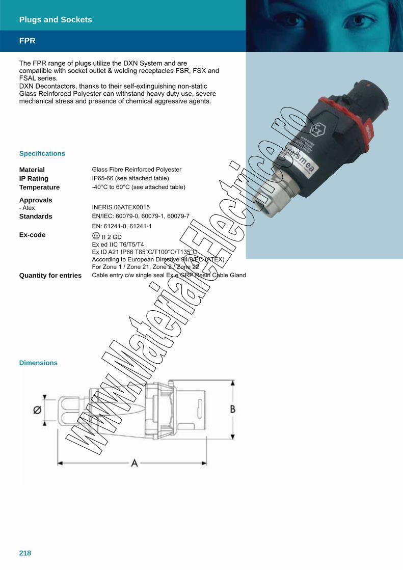
218
The FPR range of plugs utilize the DXN System and are compatible with socket outlet & welding receptacles FSR, FSX and FSAL series. DXN Decontactors, thanks to their self-extinguishing non-static Glass Reinforced Polyester can withstand heavy duty use, severe mechanical stress and presence of chemical aggressive agents.
Specifications
Material Glass Fibre Reinforced PolyesterIP Rating IP65-66 (see attached table)Temperature -40°C to 60°C (see attached table)
Approvals- Atex
INERIS 06ATEX0015
Standards EN/IEC: 60079-0, 60079-1, 60079-7
EN: 61241-0, 61241-1Ex-code II 2 GD
Ex ed IIC T6/T5/T4Ex tD A21 IP66 T85°C/T100°C/T135°CAccording to European Directive 94/9/EC (ATEX)For Zone 1 / Zone 21, Zone 2 / Zone 22
Quantity for entries Cable entry c/w single seal Ex e GRP Resin Cable Gland
FPR
Plugs and Sockets
Dimensions
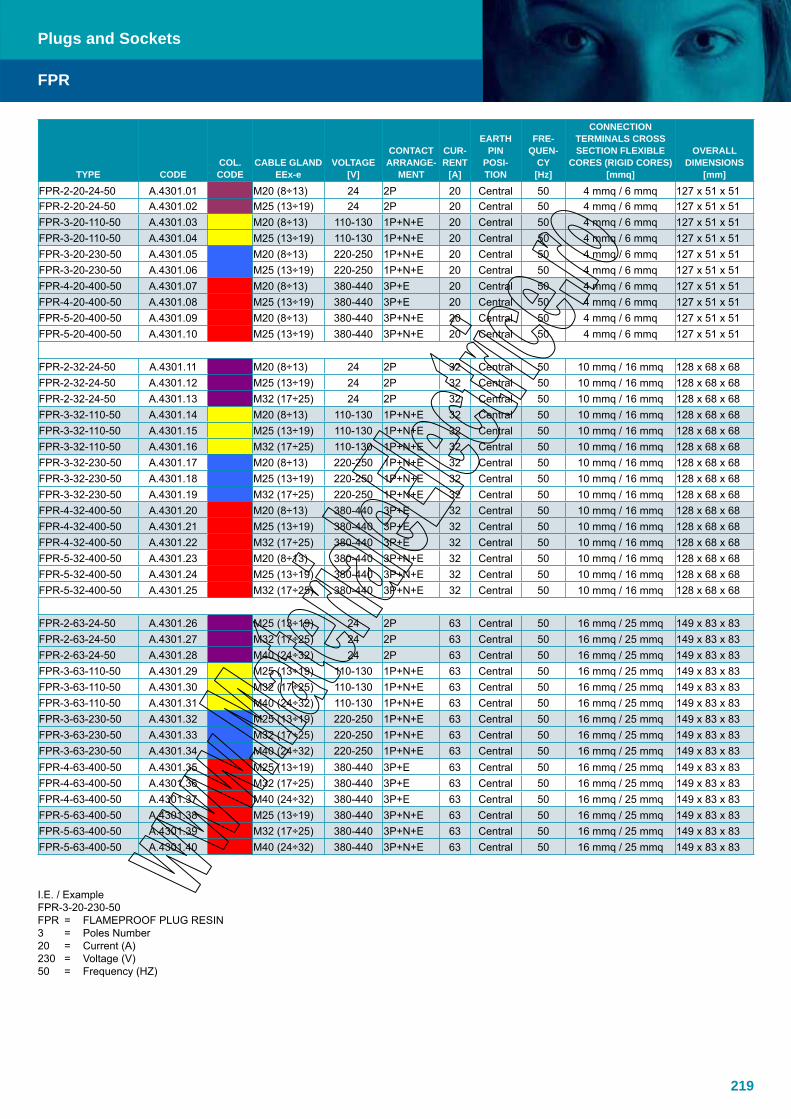
219
TYPE CODECOL. CODE
CABLE GLAND EEx-e
VOLTAGE [V]
CONTACT ARRANGE-
MENT
CUR- RENT
[A]
EARTH PIN
POSI- TION
FRE- QUEN-
CY [Hz]
CONNECTION TERMINALS CROSS SECTION FLEXIBLE
CORES (RIGID CORES) [mmq]
OVERALL DIMENSIONS
[mm]
FPR-2-20-24-50 A.4301.01 M20 (8÷13) 24 2P 20 Central 50 4 mmq / 6 mmq 127 x 51 x 51 FPR-2-20-24-50 A.4301.02 M25 (13÷19) 24 2P 20 Central 50 4 mmq / 6 mmq 127 x 51 x 51 FPR-3-20-110-50 A.4301.03 M20 (8÷13) 110-130 1P+N+E 20 Central 50 4 mmq / 6 mmq 127 x 51 x 51 FPR-3-20-110-50 A.4301.04 M25 (13÷19) 110-130 1P+N+E 20 Central 50 4 mmq / 6 mmq 127 x 51 x 51 FPR-3-20-230-50 A.4301.05 M20 (8÷13) 220-250 1P+N+E 20 Central 50 4 mmq / 6 mmq 127 x 51 x 51 FPR-3-20-230-50 A.4301.06 M25 (13÷19) 220-250 1P+N+E 20 Central 50 4 mmq / 6 mmq 127 x 51 x 51 FPR-4-20-400-50 A.4301.07 M20 (8÷13) 380-440 3P+E 20 Central 50 4 mmq / 6 mmq 127 x 51 x 51 FPR-4-20-400-50 A.4301.08 M25 (13÷19) 380-440 3P+E 20 Central 50 4 mmq / 6 mmq 127 x 51 x 51 FPR-5-20-400-50 A.4301.09 M20 (8÷13) 380-440 3P+N+E 20 Central 50 4 mmq / 6 mmq 127 x 51 x 51 FPR-5-20-400-50 A.4301.10 M25 (13÷19) 380-440 3P+N+E 20 Central 50 4 mmq / 6 mmq 127 x 51 x 51
FPR-2-32-24-50 A.4301.11 M20 (8÷13) 24 2P 32 Central 50 10 mmq / 16 mmq 128 x 68 x 68 FPR-2-32-24-50 A.4301.12 M25 (13÷19) 24 2P 32 Central 50 10 mmq / 16 mmq 128 x 68 x 68 FPR-2-32-24-50 A.4301.13 M32 (17÷25) 24 2P 32 Central 50 10 mmq / 16 mmq 128 x 68 x 68 FPR-3-32-110-50 A.4301.14 M20 (8÷13) 110-130 1P+N+E 32 Central 50 10 mmq / 16 mmq 128 x 68 x 68 FPR-3-32-110-50 A.4301.15 M25 (13÷19) 110-130 1P+N+E 32 Central 50 10 mmq / 16 mmq 128 x 68 x 68 FPR-3-32-110-50 A.4301.16 M32 (17÷25) 110-130 1P+N+E 32 Central 50 10 mmq / 16 mmq 128 x 68 x 68 FPR-3-32-230-50 A.4301.17 M20 (8÷13) 220-250 1P+N+E 32 Central 50 10 mmq / 16 mmq 128 x 68 x 68 FPR-3-32-230-50 A.4301.18 M25 (13÷19) 220-250 1P+N+E 32 Central 50 10 mmq / 16 mmq 128 x 68 x 68 FPR-3-32-230-50 A.4301.19 M32 (17÷25) 220-250 1P+N+E 32 Central 50 10 mmq / 16 mmq 128 x 68 x 68 FPR-4-32-400-50 A.4301.20 M20 (8÷13) 380-440 3P+E 32 Central 50 10 mmq / 16 mmq 128 x 68 x 68 FPR-4-32-400-50 A.4301.21 M25 (13÷19) 380-440 3P+E 32 Central 50 10 mmq / 16 mmq 128 x 68 x 68 FPR-4-32-400-50 A.4301.22 M32 (17÷25) 380-440 3P+E 32 Central 50 10 mmq / 16 mmq 128 x 68 x 68 FPR-5-32-400-50 A.4301.23 M20 (8÷13) 380-440 3P+N+E 32 Central 50 10 mmq / 16 mmq 128 x 68 x 68 FPR-5-32-400-50 A.4301.24 M25 (13÷19) 380-440 3P+N+E 32 Central 50 10 mmq / 16 mmq 128 x 68 x 68 FPR-5-32-400-50 A.4301.25 M32 (17÷25) 380-440 3P+N+E 32 Central 50 10 mmq / 16 mmq 128 x 68 x 68
FPR-2-63-24-50 A.4301.26 M25 (13÷19) 24 2P 63 Central 50 16 mmq / 25 mmq 149 x 83 x 83 FPR-2-63-24-50 A.4301.27 M32 (17÷25) 24 2P 63 Central 50 16 mmq / 25 mmq 149 x 83 x 83 FPR-2-63-24-50 A.4301.28 M40 (24÷32) 24 2P 63 Central 50 16 mmq / 25 mmq 149 x 83 x 83 FPR-3-63-110-50 A.4301.29 M25 (13÷19) 110-130 1P+N+E 63 Central 50 16 mmq / 25 mmq 149 x 83 x 83 FPR-3-63-110-50 A.4301.30 M32 (17÷25) 110-130 1P+N+E 63 Central 50 16 mmq / 25 mmq 149 x 83 x 83 FPR-3-63-110-50 A.4301.31 M40 (24÷32) 110-130 1P+N+E 63 Central 50 16 mmq / 25 mmq 149 x 83 x 83 FPR-3-63-230-50 A.4301.32 M25 (13÷19) 220-250 1P+N+E 63 Central 50 16 mmq / 25 mmq 149 x 83 x 83 FPR-3-63-230-50 A.4301.33 M32 (17÷25) 220-250 1P+N+E 63 Central 50 16 mmq / 25 mmq 149 x 83 x 83 FPR-3-63-230-50 A.4301.34 M40 (24÷32) 220-250 1P+N+E 63 Central 50 16 mmq / 25 mmq 149 x 83 x 83 FPR-4-63-400-50 A.4301.35 M25 (13÷19) 380-440 3P+E 63 Central 50 16 mmq / 25 mmq 149 x 83 x 83 FPR-4-63-400-50 A.4301.36 M32 (17÷25) 380-440 3P+E 63 Central 50 16 mmq / 25 mmq 149 x 83 x 83 FPR-4-63-400-50 A.4301.37 M40 (24÷32) 380-440 3P+E 63 Central 50 16 mmq / 25 mmq 149 x 83 x 83 FPR-5-63-400-50 A.4301.38 M25 (13÷19) 380-440 3P+N+E 63 Central 50 16 mmq / 25 mmq 149 x 83 x 83 FPR-5-63-400-50 A.4301.39 M32 (17÷25) 380-440 3P+N+E 63 Central 50 16 mmq / 25 mmq 149 x 83 x 83 FPR-5-63-400-50 A.4301.40 M40 (24÷32) 380-440 3P+N+E 63 Central 50 16 mmq / 25 mmq 149 x 83 x 83
I.E. / Example FPR-3-20-230-50 FPR = FLAMEPROOF PLUG RESIN3 = Poles Number20 = Current (A)230 = Voltage (V)50 = Frequency (HZ)
FPR
Plugs and Sockets
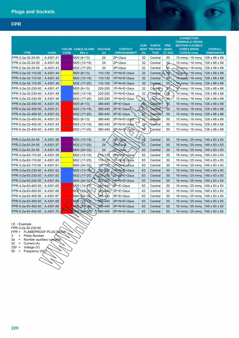
220
TYPE CODECOLOR CODE
CABLE GLAND EEx-e
VOLTAGE (V)
CONTACT ARRANGEMENT
CUR-RENT
(A)
EARTH PIN POSI-
TION
FRE-QUEN-CY (HZ)
CONNECTION TERMINALS CROSS SECTION FLEXIBLE
CORES (RIGID CORES) mmq.
OVERALL DIMENSIONS
FPR-2-2a-32-24-50 A.4301.41 M20 (8÷13) 24 2P+2aux 32 Central 50 10 mmq / 16 mmq 128 x 68 x 68 FPR-2-2a-32-24-50 A.4301.42 M25 (13÷19) 24 2P+2aux 32 Central 50 10 mmq / 16 mmq 128 x 68 x 68 FPR-2-2a-32-24-50 A.4301.43 M32 (17÷25) 24 2P+2aux 32 Central 50 10 mmq / 16 mmq 128 x 68 x 68 FPR-3-2a-32-110-50 A.4301.44 M20 (8÷13) 110-130 1P+N+E+2aux 32 Central 50 10 mmq / 16 mmq 128 x 68 x 68 FPR-3-2a-32-110-50 A.4301.45 M25 (13÷19) 110-130 1P+N+E+2aux 32 Central 50 10 mmq / 16 mmq 128 x 68 x 68 FPR-3-2a-32-110-50 A.4301.46 M32 (17÷25) 110-130 1P+N+E+2aux 32 Central 50 10 mmq / 16 mmq 128 x 68 x 68 FPR-3-2a-32-230-50 A.4301.47 M20 (8÷13) 220-250 1P+N+E+2aux 32 Central 50 10 mmq / 16 mmq 128 x 68 x 68 FPR-3-2a-32-230-50 A.4301.48 M25 (13÷19) 220-250 1P+N+E+2aux 32 Central 50 10 mmq / 16 mmq 128 x 68 x 68 FPR-3-2a-32-230-50 A.4301.49 M32 (17÷25) 220-250 1P+N+E+2aux 32 Central 50 10 mmq / 16 mmq 128 x 68 x 68 FPR-4-2a-32-400-50 A.4301.50 M20 (8÷13) 380-440 3P+E+2aux 32 Central 50 10 mmq / 16 mmq 128 x 68 x 68 FPR-4-2a-32-400-50 A.4301.51 M25 (13÷19) 380-440 3P+E+2aux 32 Central 50 10 mmq / 16 mmq 128 x 68 x 68 FPR-4-2a-32-400-50 A.4301.52 M32 (17÷25) 380-440 3P+E+2aux 32 Central 50 10 mmq / 16 mmq 128 x 68 x 68 FPR-5-2a-32-400-50 A.4301.53 M20 (8÷13) 380-440 3P+N+E+2aux 32 Central 50 10 mmq / 16 mmq 128 x 68 x 68 FPR-5-2a-32-400-50 A.4301.54 M25 (13÷19) 380-440 3P+N+E+2aux 32 Central 50 10 mmq / 16 mmq 128 x 68 x 68 FPR-5-2a-32-400-50 A.4301.55 M32 (17÷25) 380-440 3P+N+E+2aux 32 Central 50 10 mmq / 16 mmq 128 x 68 x 68
FPR-2-2a-63-24-50 A.4301.56 M25 (13÷19) 24 2P+2aux 63 Central 50 16 mmq / 25 mmq 149 x 83 x 83 FPR-2-2a-63-24-50 A.4301.57 M32 (17÷25) 24 2P+2aux 63 Central 50 16 mmq / 25 mmq 149 x 83 x 83 FPR-2-2a-63-24-50 A.4301.58 M40 (24÷32) 24 2P+2aux 63 Central 50 16 mmq / 25 mmq 149 x 83 x 83 FPR-3-2a-63-110-50 A.4301.59 M25 (13÷19) 110-130 1P+N+E+2aux 63 Central 50 16 mmq / 25 mmq 149 x 83 x 83 FPR-3-2a-63-110-50 A.4301.60 M32 (17÷25) 110-130 1P+N+E+2aux 63 Central 50 16 mmq / 25 mmq 149 x 83 x 83 FPR-3-2a-63-110-50 A.4301.61 M40 (24÷32) 110-130 1P+N+E+2aux 63 Central 50 16 mmq / 25 mmq 149 x 83 x 83 FPR-3-2a-63-230-50 A.4301.62 M25 (13÷19) 220-250 1P+N+E+2aux 63 Central 50 16 mmq / 25 mmq 149 x 83 x 83 FPR-3-2a-63-230-50 A.4301.63 M32 (17÷25) 220-250 1P+N+E+2aux 63 Central 50 16 mmq / 25 mmq 149 x 83 x 83 FPR-3-2a-63-230-50 A.4301.64 M40 (24÷32) 220-250 1P+N+E+2aux 63 Central 50 16 mmq / 25 mmq 149 x 83 x 83 FPR-4-2a-63-400-50 A.4301.65 M25 (13÷19) 380-440 3P+E+2aux 63 Central 50 16 mmq / 25 mmq 149 x 83 x 83 FPR-4-2a-63-400-50 A.4301.66 M32 (17÷25) 380-440 3P+E+2aux 63 Central 50 16 mmq / 25 mmq 149 x 83 x 83 FPR-4-2a-63-400-50 A.4301.67 M40 (24÷32) 380-440 3P+E+2aux 63 Central 50 16 mmq / 25 mmq 149 x 83 x 83 FPR-5-2a-63-400-50 A.4301.68 M25 (13÷19) 380-440 3P+N+E+2aux 63 Central 50 16 mmq / 25 mmq 149 x 83 x 83 FPR-5-2a-63-400-50 A.4301.69 M32 (17÷25) 380-440 3P+N+E+2aux 63 Central 50 16 mmq / 25 mmq 149 x 83 x 83 FPR-5-2a-63-400-50 A.4301.70 M40 (24÷32) 380-440 3P+N+E+2aux 63 Central 50 16 mmq / 25 mmq 149 x 83 x 83
I.E. / Example FPR-3-2a-32-230-50 FPR = FLAMEPROOF PLUG RESIN 3 = Poles Number 2a = Number auxiliary contacts 32 = Current (A) 230 = Voltage (V) 50 = Frequency (HZ)
FPR
Plugs and Sockets
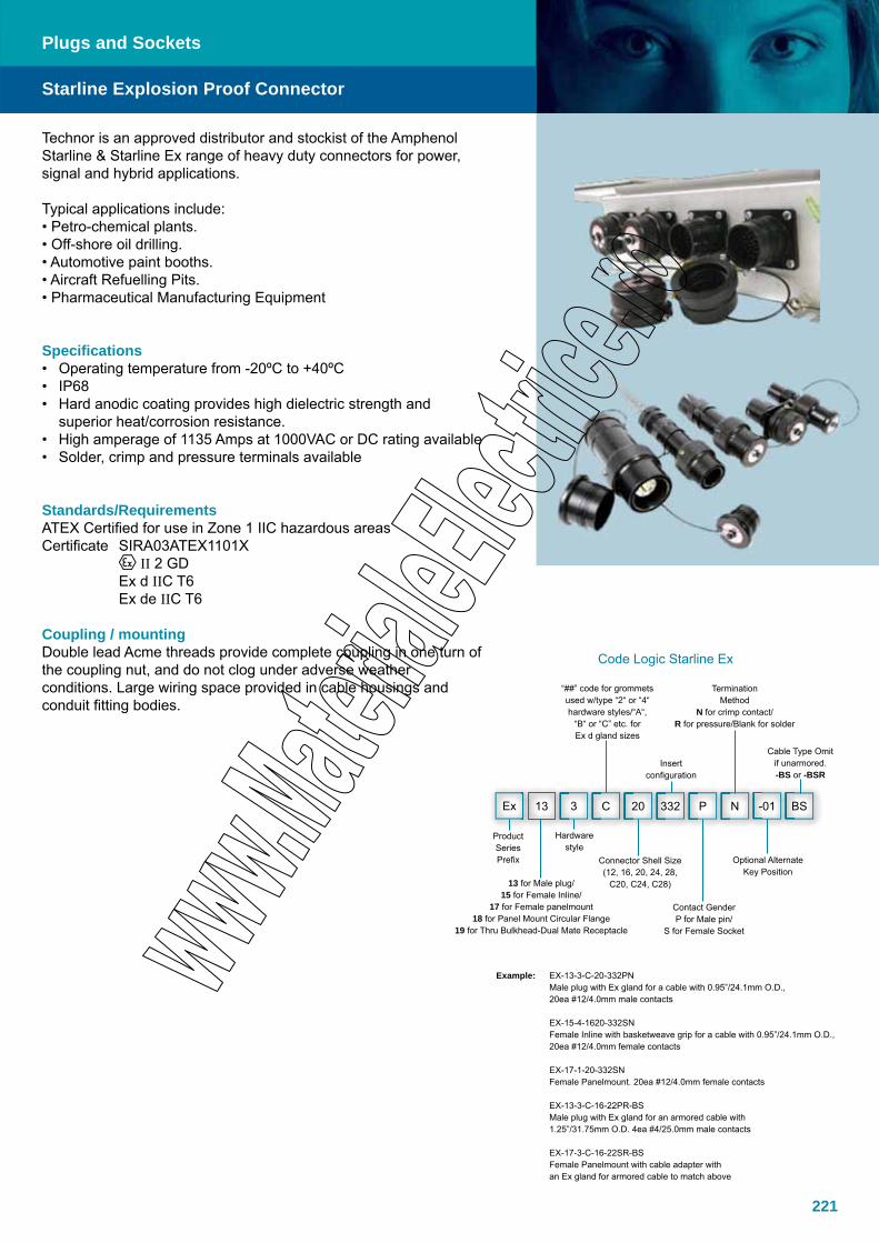
221
Starline Explosion Proof Connector
Plugs and Sockets
Technor is an approved distributor and stockist of the Amphenol Starline & Starline Ex range of heavy duty connectors for power, signal and hybrid applications.
Typical applications include:• Petro-chemical plants.• Off-shore oil drilling.• Automotive paint booths.• Aircraft Refuelling Pits.• Pharmaceutical Manufacturing Equipment
Specifications• Operating temperature from -20ºC to +40ºC • IP68• Hard anodic coating provides high dielectric strength and
superior heat/corrosion resistance.• High amperage of 1135 Amps at 1000VAC or DC rating available• Solder, crimp and pressure terminals available
Standards/RequirementsATEX Certified for use in Zone 1 IIC hazardous areas Certificate SIRA03ATEX1101X II 2 GD Ex d IIC T6 Ex de IIC T6
Coupling / mountingDouble lead Acme threads provide complete coupling in one turn of the coupling nut, and do not clog under adverse weather conditions. Large wiring space provided in cable housings and conduit fitting bodies.
Code Logic Starline Ex
Ex 13 3 C 20 332 P N -01 BS
“##” code for grommets used w/type “2“ or “4“ hardware styles/“A“,
“B“ or “C” etc. for Ex d gland sizes
Insert configuration
TerminationMethod
N for crimp contact/R for pressure/Blank for solder
Cable Type Omit if unarmored.-BS or -BSR
ProductSeriesPrefix
13 for Male plug/15 for Female Inline/
17 for Female panelmount18 for Panel Mount Circular Flange
19 for Thru Bulkhead-Dual Mate Receptacle
Hardware style
Connector Shell Size(12, 16, 20, 24, 28,
C20, C24, C28)
Contact GenderP for Male pin/
S for Female Socket
Optional Alternate Key Position
Example: EX-13-3-C-20-332PN Male plug with Ex gland for a cable with 0.95”/24.1mm O.D., 20ea #12/4.0mm male contacts
EX-15-4-1620-332SN Female Inline with basketweave grip for a cable with 0.95”/24.1mm O.D., 20ea #12/4.0mm female contacts
EX-17-1-20-332SN Female Panelmount. 20ea #12/4.0mm female contacts
EX-13-3-C-16-22PR-BS Male plug with Ex gland for an armored cable with 1.25”/31.75mm O.D. 4ea #4/25.0mm male contacts
EX-17-3-C-16-22SR-BS Female Panelmount with cable adapter with an Ex gland for armored cable to match above
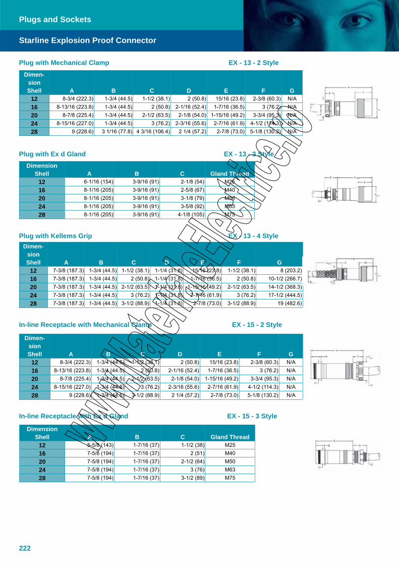
222
Dimen-sionShell A B C D E F G
12 8-3/4 (222.3) 1-3/4 (44.5) 1-1/2 (38.1) 2 (50.8) 15/16 (23.8) 2-3/8 (60.3) N/A16 8-13/16 (223.8) 1-3/4 (44.5) 2 (50.8) 2-1/16 (52.4) 1-7/16 (36.5) 3 (76.2) N/A20 8-7/8 (225.4) 1-3/4 (44.5) 2-1/2 (63.5) 2-1/8 (54.0) 1-15/16 (49.2) 3-3/4 (95.3) N/A24 8-15/16 (227.0) 1-3/4 (44.5) 3 (76.2) 2-3/16 (55.6) 2-7/16 (61.9) 4-1/2 (114.3) N/A28 9 (228.6) 3 1/16 (77.8) 4 3/16 (106.4) 2 1/4 (57.2) 2-7/8 (73.0) 5-1/8 (130.2) N/A
DimensionShell A B C Gland Thread
12 6-1/16 (154) 3-9/16 (91) 2-1/8 (54) M2516 8-1/16 (205) 3-9/16 (91) 2-5/8 (67) M4020 8-1/16 (205) 3-9/16 (91) 3-1/8 (79) M5024 8-1/16 (205) 3-9/16 (91) 3-5/8 (92) M6328 8-1/16 (205) 3-9/16 (91) 4-1/8 (105) M75
Dimen-sionShell A B C D E F G
12 7-3/8 (187.3) 1-3/4 (44.5) 1-1/2 (38.1) 1-1/4 (31.8) 15/16 (23.8) 1-1/2 (38.1) 8 (203.2)16 7-3/8 (187.3) 1-3/4 (44.5) 2 (50.8) 1-1/4 (31.8) 1-7/16 (36.5) 2 (50.8) 10-1/2 (266.7)20 7-3/8 (187.3) 1-3/4 (44.5) 2-1/2 (63.5) 1-1/4 (31.8) 1-15/16 (49.2) 2-1/2 (63.5) 14-1/2 (368.3)24 7-3/8 (187.3) 1-3/4 (44.5) 3 (76.2) 1-1/4 (31.8) 2-7/16 (61.9) 3 (76.2) 17-1/2 (444.5)28 7-3/8 (187.3) 1-3/4 (44.5) 3-1/2 (88.9) 1-1/4 (31.8) 2-7/8 (73.0) 3-1/2 (88.9) 19 (482.6)
Dimen-sionShell A B C D E F G
12 8-3/4 (222.3) 1-3/4 (44.5) 1-1/2 (38.1) 2 (50.8) 15/16 (23.8) 2-3/8 (60.3) N/A16 8-13/16 (223.8) 1-3/4 (44.5) 2 (50.8) 2-1/16 (52.4) 1-7/16 (36.5) 3 (76.2) N/A20 8-7/8 (225.4) 1-3/4 (44.5) 2-1/2 (63.5) 2-1/8 (54.0) 1-15/16 (49.2) 3-3/4 (95.3) N/A24 8-15/16 (227.0) 1-3/4 (44.5) 3 (76.2) 2-3/16 (55.6) 2-7/16 (61.9) 4-1/2 (114.3) N/A28 9 (228.6) 1-3/4 (44.5) 3-1/2 (88.9) 2 1/4 (57.2) 2-7/8 (73.0) 5-1/8 (130.2) N/A
Plug with Mechanical Clamp EX - 13 - 2 Style
Plug with Ex d Gland EX - 13 - 3 Style
Plug with Kellems Grip EX - 13 - 4 Style
In-line Receptacle with Mechanical Clamp EX - 15 - 2 Style
In-line Receptacle with Ex d Gland EX - 15 - 3 Style
Starline Explosion Proof Connector
Plugs and Sockets
DimensionShell A B C Gland Thread
12 5-5/8 (143) 1-7/16 (37) 1-1/2 (38) M2516 7-5/8 (194) 1-7/16 (37) 2 (51) M4020 7-5/8 (194) 1-7/16 (37) 2-1/2 (64) M5024 7-5/8 (194) 1-7/16 (37) 3 (76) M6328 7-5/8 (194) 1-7/16 (37) 3-1/2 (89) M75

223
DimensionShell A B C D E H
12 4-3/4 (120.7) 1-3/4 (44.5) 1-1/2 (38.1) 1.654 (42) 2-1/4 (57.2) M4016 4-3/4 (120.7) 1-3/4 (44.5) 2 (50.8) 2.047 (52) 2-5/8 (66.7) M5020 4-3/4 (120.7) 1-3/4 (44.5) 2-1/2 (63.5) 2.441 (62) 3 (76.2) M6324 4-3/4 (120.7) 1-3/4 (44.5) 3 (76.2) 2.835 (72) 3-1/2 (88.9) M7528 4-3/4 (120.7) 1-3/4 (44.5) 3-1/2 (88.9) 3.228 (82) 4 (101.6) M90
DimensionShell A B C D E F
12 8-3/4 (222.3) 1-3/4 (44.5) 1-1/2 (38.1) 2 (50.8) 15/16 (23.8) 2-3/8 (60.3)16 8-13/16 (223.8) 1-3/4 (44.5) 2 (50.8) 2-1/16 (52.4) 1-7/16 (36.5) 3 (76.2)20 8-7/8 (225.4) 1-3/4 (44.5) 2-1/2 (63.5) 2-1/8 (54.0) 1-15/16 (49.2) 3-3/4 (95.3)24 8-15/16 (227.0) 1-3/4 (44.5) 3 (76.2) 2-3/16 (55.6) 2-7/16 (61.9) 4-1/2 (114.3)28 9 (228.6) 1-3/4 (44.5) 3-1/2 (88.9) 2 1/4 (57.2)
Dimen-sionShell A B C D E F G
12 7-3/8 (187.3) 1-3/4 (44.5) 1-1/2 (38.1) 1-1/4 (31.8) 15/16 (23.8) 1-1/2 (38.1) 8 (203.2)16 7-3/8 (187.3) 1-3/4 (44.5) 2 (50.8) 1-1/4 (31.8) 1-7/16 (36.5) 2 (50.8) 10-1/2 (266.7)20 7-3/8 (187.3) 1-3/4 (44.5) 2-1/2 (63.5) 1-1/4 (31.8) 1-15/16 (49.2) 2-1/2 (63.5) 14-1/2 (368.3)24 7-3/8 (187.3) 1-3/4 (44.5) 3 (76.2) 1-1/4 (31.8) 2-7/16 (61.9) 3 (76.2) 17-1/2 (444.5)28 7-3/8 (187.3) 1-3/4 (44.5) 3-1/2 (88.9) 1-1/4 (31.8) 2-7/8 (73.0) 3-1/2 (88.9) 19 (482.6)
Panel Mount Receptacle (Potting Required) EX - 17 - 1 Style
Fixed In-line Receptacle with Mechanical clamp EX - 17 - 2 Style
Fixed In-line Receptacle with Ex d Gland EX - 17 - 3 Style
Fixed In-line Receptable with Kellems Grip EX - 17 - 4 Style
DimensionShell A B C D E F G
12 7-3/8 (187.3) 1-3/4 (44.5) 1-1/2 (38.1) 1-1/4 (31.8) 15/16 (23.8) 1-1/2 (38.1) 8 (203.2)16 7-3/8 (187.3) 1-3/4 (44.5) 2 (50.8) 1-1/4 (31.8) 1-7/16 (36.5) 2 (50.8) 10-1/2 (266.7)20 7-3/8 (187.3) 1-3/4 (44.5) 2-1/2 (63.5) 1-1/4 (31.8) 1-15/16 (49.2) 2-1/2 (63.5) 14-1/2 (368.3)24 7-3/8 (187.3) 1-3/4 (44.5) 3 (76.2) 1-1/4 (31.8) 2-7/16 (61.9) 3 (76.2) 17-1/2 (444.5)28 7-3/8 (187.3) 1-3/4 (44.5) 3-1/2 (88.9) 1-1/4 (31.8) 2-7/8 (73.0) 3-1/2 (88.9) 19 (482.6)
In-line Receptacle with Kellems Grip EX - 15 - 4 Style
Starline Explosion Proof Connector
Plugs and Sockets
DimensionShell A B C Gland Thread
12 5-5/8 (143) 1-7/16 (37) 1-1/2 (38) M2516 7-7/8 (194) 1-7/16 (37) 2 (51) M4020 7-7/8 (194) 1-7/16 (37) 1-/12 (64) M5024 7-7/8 (194) 1-7/16 (37) 3 (76) M6328 7-7/8 (194) 1-7/16 (37) 3-1/2 (89) M75
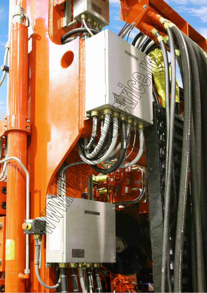
224
225
Gas Detection
TN 2000-4Mobile Gas Detection System, Ex de, AISI316L 226
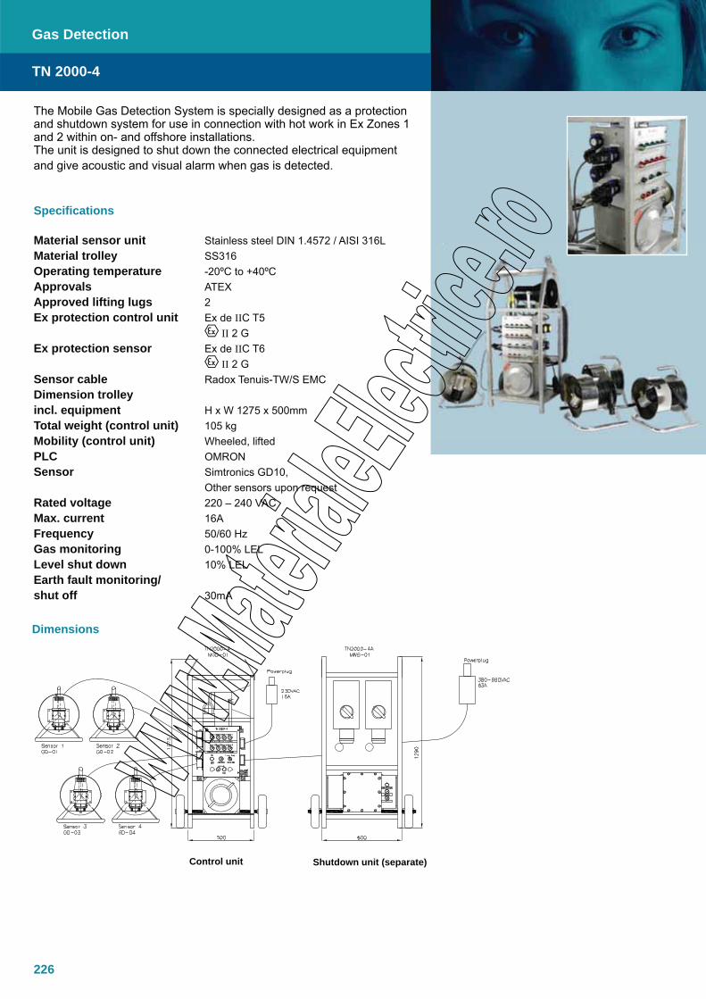
226
The Mobile Gas Detection System is specially designed as a protection and shutdown system for use in connection with hot work in Ex Zones 1 and 2 within on- and offshore installations. The unit is designed to shut down the connected electrical equipment and give acoustic and visual alarm when gas is detected.
Specifications
Material sensor unit Stainless steel DIN 1.4572 / AISI 316LMaterial trolley SS316 Operating temperature -20ºC to +40ºCApprovals ATEXApproved lifting lugs 2Ex protection control unit Ex de IIC T5 II 2 GEx protection sensor Ex de IIC T6 II 2 GSensor cable Radox Tenuis-TW/S EMCDimension trolleyincl. equipment H x W 1275 x 500mmTotal weight (control unit) 105 kgMobility (control unit) Wheeled, liftedPLC OMRONSensor Simtronics GD10, Other sensors upon requestRated voltage 220 – 240 VACMax. current 16AFrequency 50/60 HzGas monitoring 0-100% LEL Level shut down 10% LELEarth fault monitoring/shut off 30mA
TN 2000-4
Gas Detection
Dimensions
Control unit Shutdown unit (separate)
Related Documents