Top Banner
SolidWorks Basics
21

SolidWorks Basics - Massachusetts Institute of Technology · SolidWorks Basics. SolidWorks Navigation Feature Tree Command Bar Model Window. Simple Box Select the “Front” plane

Feb 21, 2020

Download

Documents

dariahiddleston
Welcome message from author
This document is posted to help you gain knowledge. Please leave a comment to let me know what you think about it! Share it to your friends and learn new things together.
Transcript
Page 1: SolidWorks Basics - Massachusetts Institute of Technology · SolidWorks Basics. SolidWorks Navigation Feature Tree Command Bar Model Window. Simple Box Select the “Front” plane

SolidWorks Basics

Page 2: SolidWorks Basics - Massachusetts Institute of Technology · SolidWorks Basics. SolidWorks Navigation Feature Tree Command Bar Model Window. Simple Box Select the “Front” plane

SolidWorks Navigation

Feature Tree

Command Bar

Model Window

Page 3: SolidWorks Basics - Massachusetts Institute of Technology · SolidWorks Basics. SolidWorks Navigation Feature Tree Command Bar Model Window. Simple Box Select the “Front” plane

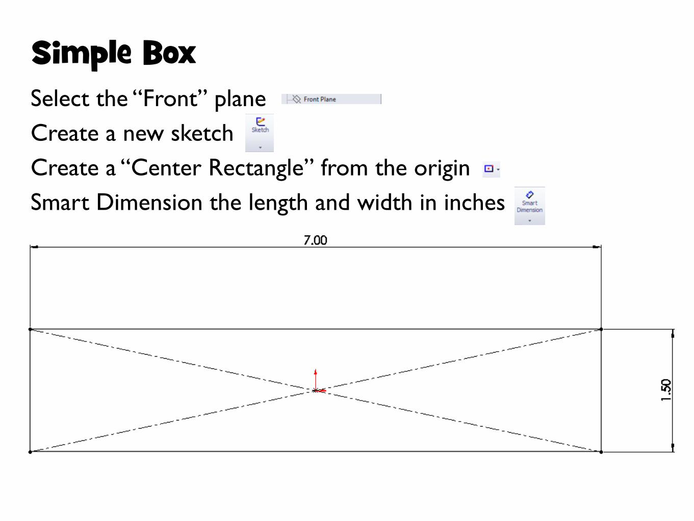
Simple BoxSelect the “Front” planeCreate a new sketchCreate a “Center Rectangle” from the originSmart Dimension the length and width in inches

Page 4: SolidWorks Basics - Massachusetts Institute of Technology · SolidWorks Basics. SolidWorks Navigation Feature Tree Command Bar Model Window. Simple Box Select the “Front” plane

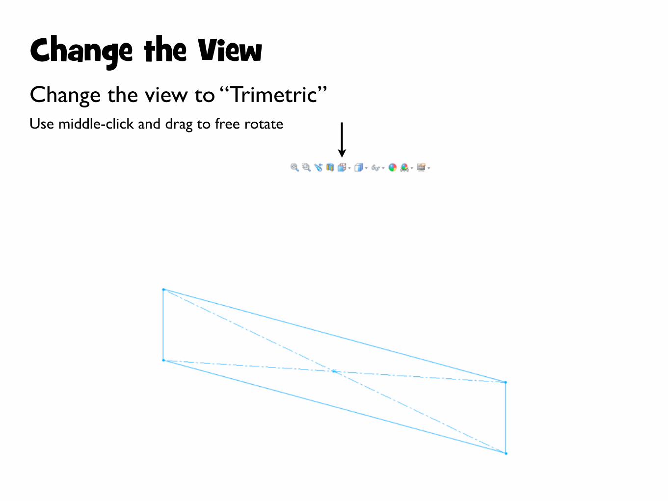
Change the ViewChange the view to “Trimetric”Use middle-click and drag to free rotate

Page 5: SolidWorks Basics - Massachusetts Institute of Technology · SolidWorks Basics. SolidWorks Navigation Feature Tree Command Bar Model Window. Simple Box Select the “Front” plane

ExtrudeExtrude the sketchChoose “Mid Plane”, and set to 3.125"

Page 6: SolidWorks Basics - Massachusetts Institute of Technology · SolidWorks Basics. SolidWorks Navigation Feature Tree Command Bar Model Window. Simple Box Select the “Front” plane

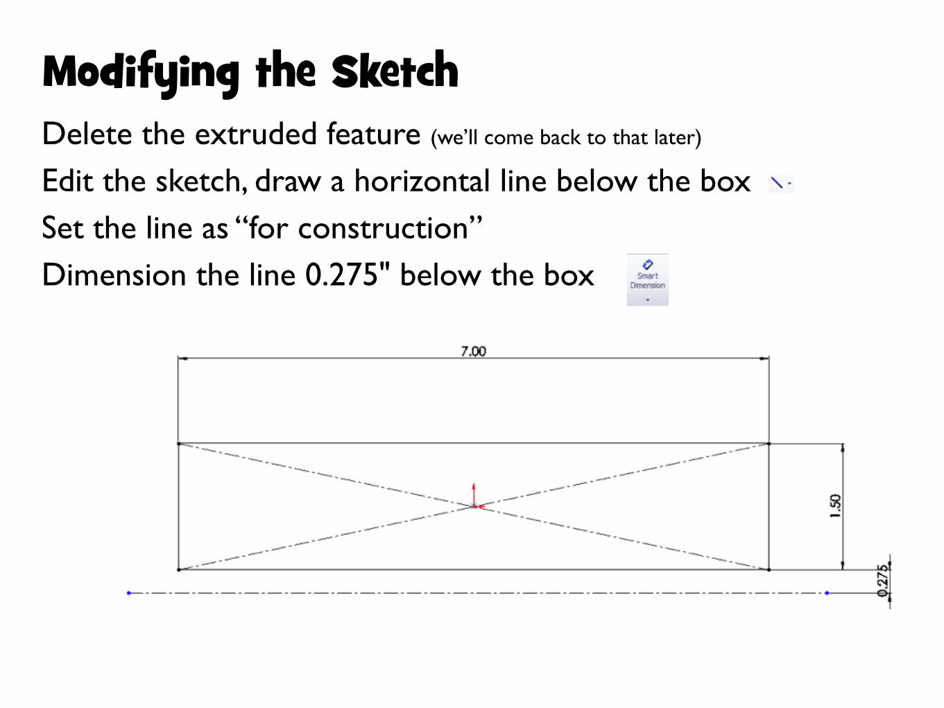
Modifying the SketchDelete the extruded feature (we’ll come back to that later)

Edit the sketch, draw a horizontal line below the boxSet the line as “for construction”Dimension the line 0.275" below the box

Page 7: SolidWorks Basics - Massachusetts Institute of Technology · SolidWorks Basics. SolidWorks Navigation Feature Tree Command Bar Model Window. Simple Box Select the “Front” plane

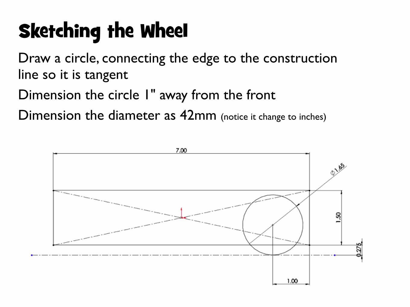
Sketching the WheelDraw a circle, connecting the edge to the construction line so it is tangentDimension the circle 1" away from the frontDimension the diameter as 42mm (notice it change to inches)

Page 8: SolidWorks Basics - Massachusetts Institute of Technology · SolidWorks Basics. SolidWorks Navigation Feature Tree Command Bar Model Window. Simple Box Select the “Front” plane

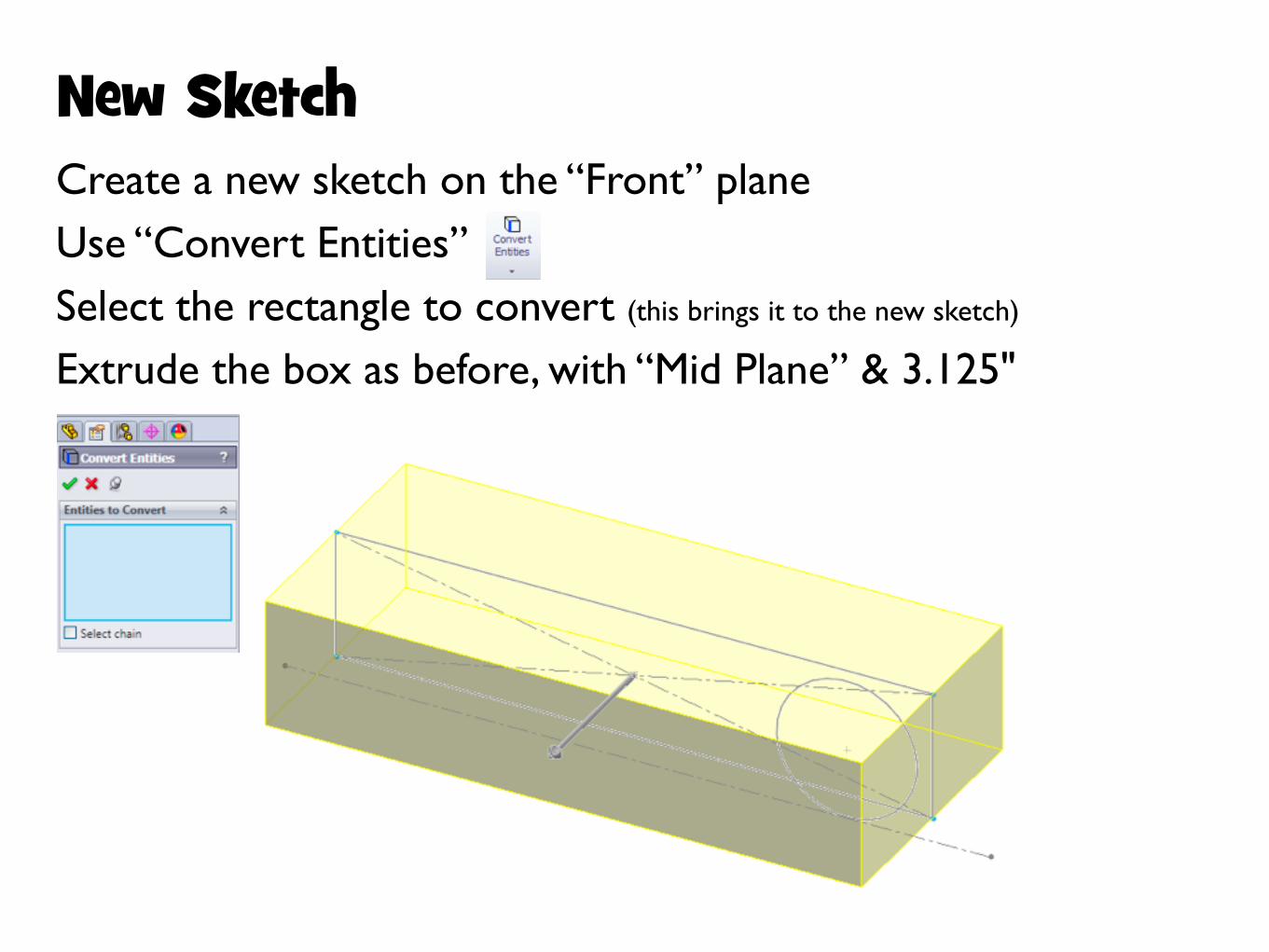
New SketchCreate a new sketch on the “Front” planeUse “Convert Entities”Select the rectangle to convert (this brings it to the new sketch)

Extrude the box as before, with “Mid Plane” & 3.125"

Page 9: SolidWorks Basics - Massachusetts Institute of Technology · SolidWorks Basics. SolidWorks Navigation Feature Tree Command Bar Model Window. Simple Box Select the “Front” plane

Reference PlaneIn the top menu, choose:“Insert > Reference Geometry > Plane”Set the plane 0.10" away from the box face

Page 10: SolidWorks Basics - Massachusetts Institute of Technology · SolidWorks Basics. SolidWorks Navigation Feature Tree Command Bar Model Window. Simple Box Select the “Front” plane

New SketchCreate a new sketch on the new reference planeUse “Convert Entities” againSelect the circle to bring it onto this new sketch

Page 11: SolidWorks Basics - Massachusetts Institute of Technology · SolidWorks Basics. SolidWorks Navigation Feature Tree Command Bar Model Window. Simple Box Select the “Front” plane

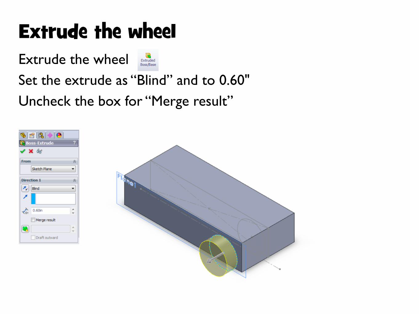
Extrude the wheelExtrude the wheelSet the extrude as “Blind” and to 0.60"Uncheck the box for “Merge result”

Page 12: SolidWorks Basics - Massachusetts Institute of Technology · SolidWorks Basics. SolidWorks Navigation Feature Tree Command Bar Model Window. Simple Box Select the “Front” plane

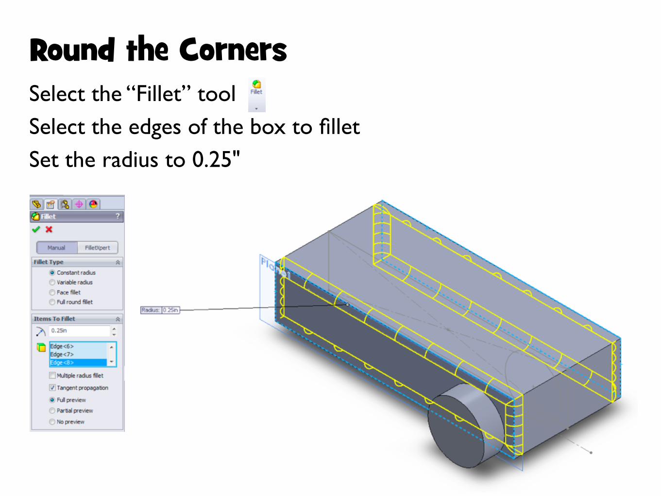
Round the CornersSelect the “Fillet” toolSelect the edges of the box to filletSet the radius to 0.25"

Page 13: SolidWorks Basics - Massachusetts Institute of Technology · SolidWorks Basics. SolidWorks Navigation Feature Tree Command Bar Model Window. Simple Box Select the “Front” plane

Round the Edges of the WheelsSelect the “Fillet” toolSelect the edges of the wheel to filletSet the radius to 0.125"

Page 14: SolidWorks Basics - Massachusetts Institute of Technology · SolidWorks Basics. SolidWorks Navigation Feature Tree Command Bar Model Window. Simple Box Select the “Front” plane

Mirror the WheelsSelect the “Mirror” toolChoose to mirror about the “Front” planeGo to “Bodies to Mirror”, then click on the wheel in the model window (you can check preview to see what will happen)

Page 15: SolidWorks Basics - Massachusetts Institute of Technology · SolidWorks Basics. SolidWorks Navigation Feature Tree Command Bar Model Window. Simple Box Select the “Front” plane

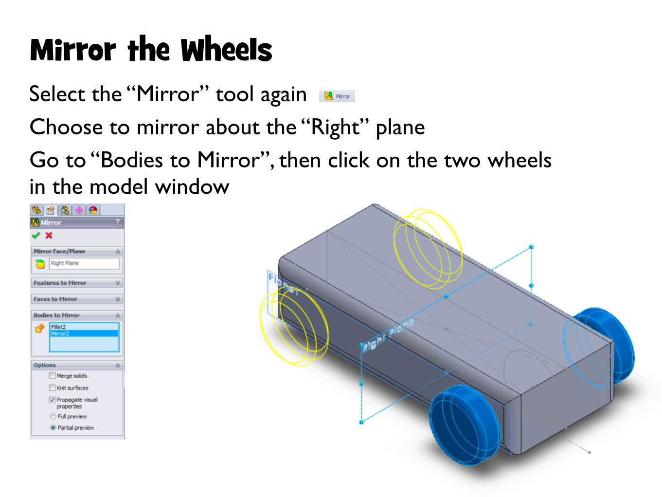
Mirror the WheelsSelect the “Mirror” tool againChoose to mirror about the “Right” planeGo to “Bodies to Mirror”, then click on the two wheels in the model window

Page 16: SolidWorks Basics - Massachusetts Institute of Technology · SolidWorks Basics. SolidWorks Navigation Feature Tree Command Bar Model Window. Simple Box Select the “Front” plane

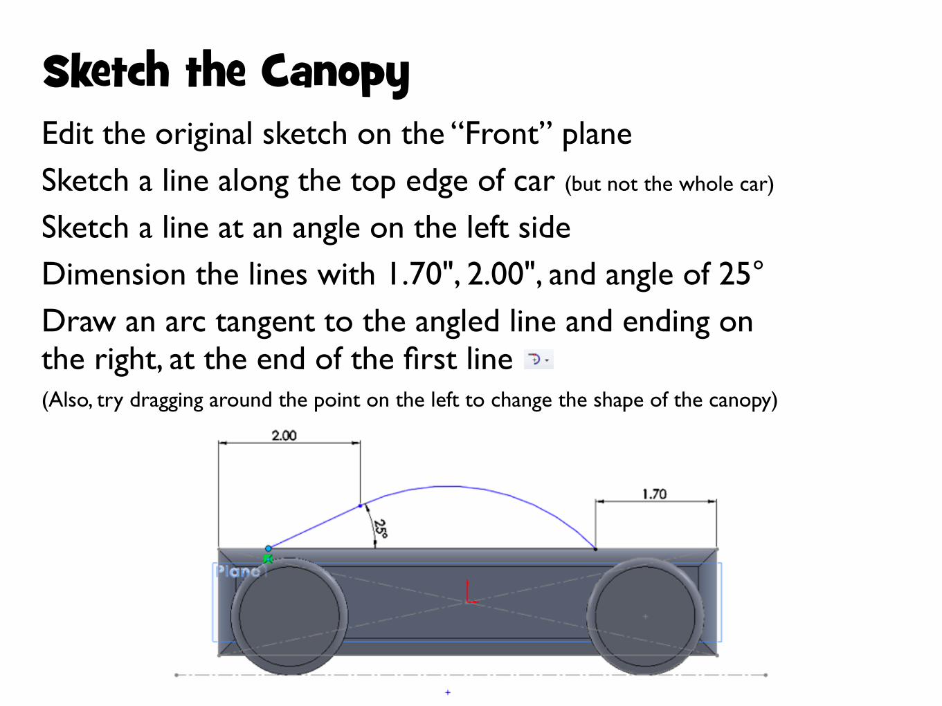
Sketch the CanopyEdit the original sketch on the “Front” planeSketch a line along the top edge of car (but not the whole car)

Sketch a line at an angle on the left sideDimension the lines with 1.70", 2.00", and angle of 25°Draw an arc tangent to the angled line and ending on the right, at the end of the first line(Also, try dragging around the point on the left to change the shape of the canopy)

Page 17: SolidWorks Basics - Massachusetts Institute of Technology · SolidWorks Basics. SolidWorks Navigation Feature Tree Command Bar Model Window. Simple Box Select the “Front” plane

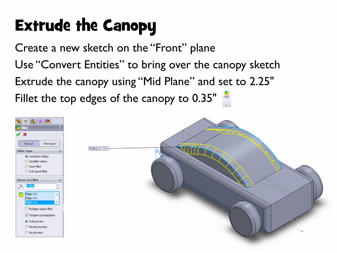
Extrude the CanopyCreate a new sketch on the “Front” planeUse “Convert Entities” to bring over the canopy sketch Extrude the canopy using “Mid Plane” and set to 2.25"Fillet the top edges of the canopy to 0.35"

Page 18: SolidWorks Basics - Massachusetts Institute of Technology · SolidWorks Basics. SolidWorks Navigation Feature Tree Command Bar Model Window. Simple Box Select the “Front” plane

Hide the BodyRight click on the feature for the car body, and choose “Hide” to make it invisibleRotate the view to see the underside of the canopy

Right click to “Hide”

Page 19: SolidWorks Basics - Massachusetts Institute of Technology · SolidWorks Basics. SolidWorks Navigation Feature Tree Command Bar Model Window. Simple Box Select the “Front” plane

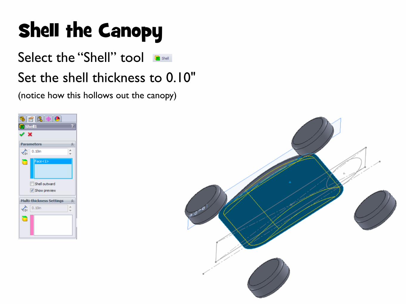
Shell the CanopySelect the “Shell” toolSet the shell thickness to 0.10"(notice how this hollows out the canopy)

Page 20: SolidWorks Basics - Massachusetts Institute of Technology · SolidWorks Basics. SolidWorks Navigation Feature Tree Command Bar Model Window. Simple Box Select the “Front” plane

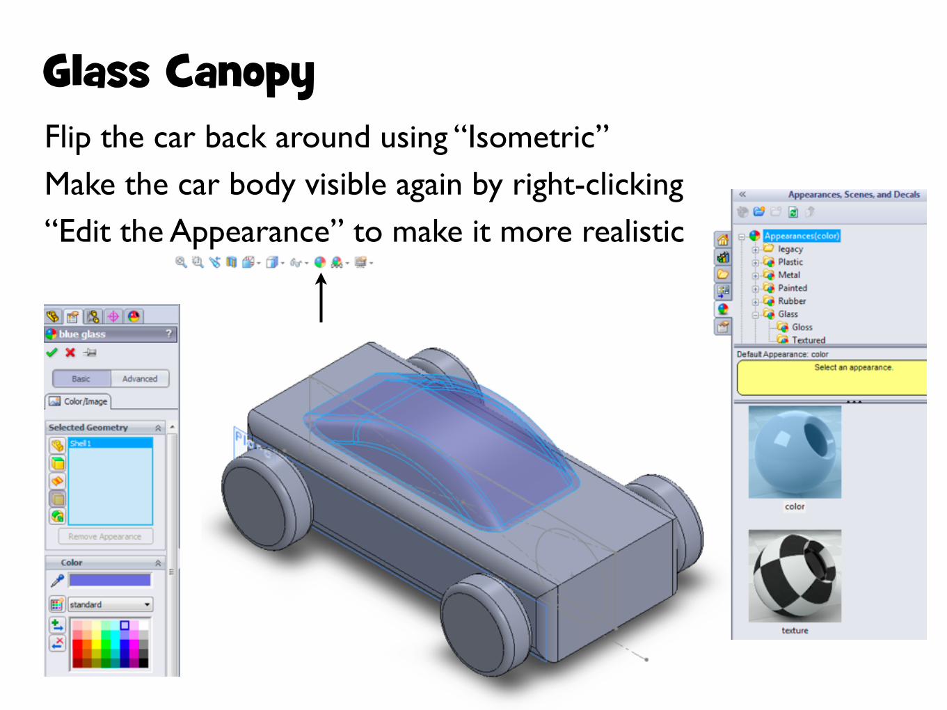
Glass CanopyFlip the car back around using “Isometric”Make the car body visible again by right-clicking“Edit the Appearance” to make it more realistic

Page 21: SolidWorks Basics - Massachusetts Institute of Technology · SolidWorks Basics. SolidWorks Navigation Feature Tree Command Bar Model Window. Simple Box Select the “Front” plane

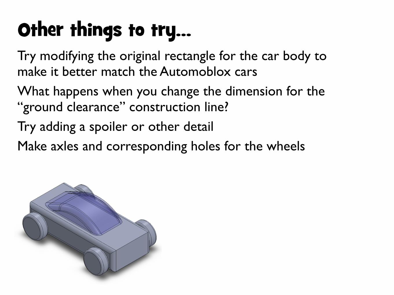
Other things to try...Try modifying the original rectangle for the car body to make it better match the Automoblox carsWhat happens when you change the dimension for the “ground clearance” construction line?Try adding a spoiler or other detailMake axles and corresponding holes for the wheels