SolidWorks 2000 CreoScitex Training 22/May/2000 Page 1 of 78

Welcome message from author
This document is posted to help you gain knowledge. Please leave a comment to let me know what you think about it! Share it to your friends and learn new things together.
Transcript

SolidWorks 2000 CreoScitex Training
22/May/2000 Page 1 of 78

SolidWorks 2000 CreoScitex Training
22/May/2000 Page 2 of 78
Table of Contents TABLE OF CONTENTS ................................................................................................... 2 LEVEL 2....................................................................................................................... 5
Audience: Proficient SolidWorks users .................................................................... 5 Course Objectives ................................................................................................... 5
PLANE OVERVIEW........................................................................................................ 6 Offset Plane............................................................................................................. 6 Plane at Angle......................................................................................................... 7 Three Point Plane.................................................................................................... 7 Parallel Plane at Point ............................................................................................ 8 Line and Point Plane............................................................................................... 8 Perpendicular to Curve at Point Plane .................................................................... 9
FILE LOCATIONS ........................................................................................................ 10 PALETTE FEATURES AND LIBRARY FEATURES - SIMILARITIES AND DIFFERENCES......... 11
Mandatory References........................................................................................... 12 ADD CONFIGURATION/CONFIGURATION PROPERTIES .................................................. 13
Configuration example – extend & retract cylinder ............................................... 14 Configuration examples – detailed & “simplified”................................................ 14 Suppress and Unsuppress Features ....................................................................... 15
MANAGING PART AND ASSEMBLY FILES. ..................................................................... 16 Simplifying Large Assemblies ................................................................................ 16 Lightweight Parts .................................................................................................. 16 Assembly Features................................................................................................. 17 Replacing a Single Instance of an Assembly Component........................................ 17 Preserving Mates with Component Replacement ................................................... 18 What's Wrong? ...................................................................................................... 18 Alternative Method for Editing an Exploded View ................................................. 19
RIB FEATURE ............................................................................................................. 20 Add Rib Feature Example...................................................................................... 21
PARTING LINE DRAFT ................................................................................................ 22 THIN FEATURE ........................................................................................................... 23
Thin Feature Base Extrude .................................................................................... 23 MIRROR FEATURE ...................................................................................................... 25 SHEET METAL............................................................................................................ 26
Bend Allowance Options........................................................................................ 27 Bend Table ........................................................................................................ 27 K-factor............................................................................................................. 28 Bend Allowance Value ...................................................................................... 28
Sheet Metal Features ............................................................................................. 29 FeatureManager Design Tree............................................................................. 29
Rollback Bar ......................................................................................................... 30 Edit Bends ............................................................................................................. 31
Edit a Single Bend ............................................................................................. 31 Edit Bends for Entire Part .................................................................................. 32 Edit Bends Listed Under Flatten-Bends ............................................................. 32

SolidWorks 2000 CreoScitex Training
22/May/2000 Page 3 of 79
Edit Bends Listed Under Process-Bends ............................................................ 32 Adding Walls to a Sheet Metal Part ....................................................................... 33 Extruding Tabs on a Sheet Metal Part ................................................................... 34 Rip ........................................................................................................................ 35 Auto Relief............................................................................................................. 36
Edit a Single Auto Relief ................................................................................... 37 Edit All Auto Reliefs ......................................................................................... 37
Creating Drawings of Sheet Metal Parts ............................................................... 38 Automatic Sheet Metal Drawings ...................................................................... 39 Manual Sheet Metal Drawings ........................................................................... 39
Notes ..................................................................................................................... 40 Annotation Properties ........................................................................................... 41 ANSI Weld Symbol................................................................................................. 42
GEOMETRIC TOLERANCING ........................................................................................ 43 FIRST ANGLE AND THIRD ANGLE PROJECTION ............................................................ 44 SHEET SETUP ............................................................................................................. 45
Modifying the Sheet Setup...................................................................................... 46 Projection View ..................................................................................................... 47
MANINTAING COMPANY STANDARDS ......................................................................... 48 Use of Template files ............................................................................................. 48
Standard Borders ............................................................................................... 48 LINKING NOTES TO DOCUMENT PROPERTIES............................................................... 50 COSMETIC THREADS .................................................................................................. 51 STACKED BALLOONS.................................................................................................. 52 BILL OF MATERIALS................................................................................................... 54
Bill of Materials - Custom Properties .................................................................... 55 Summary Info – Custom ........................................................................................ 56
DETAILING OVERVIEW ............................................................................................... 57 Insert Model Items................................................................................................. 57 Moving and Copying Dimensions .......................................................................... 58 Aligning Dimensions ............................................................................................. 59
Aligned Parallel ......................................................................................... 59 Center Marks......................................................................................................... 60 Hole Callouts ........................................................................................................ 60
RAPIDDRAFT DRAWINGS............................................................................................ 61 SOLIDWORKS EXPLORER -- OVERVIEW ...................................................................... 62
Preview ............................................................................................................. 65 Preview Example............................................................................................... 65 Custom Properties ............................................................................................. 66 Properties Summary .......................................................................................... 67 Configuration Specific....................................................................................... 68 Show References ............................................................................................... 69
Show References Example............................................................................. 69 Property Search ................................................................................................. 71
Property Search Example............................................................................... 72 Edit Hyperlinks ................................................................................................. 73

SolidWorks 2000 CreoScitex Training
22/May/2000 Page 4 of 80
Where Used....................................................................................................... 73 Where Used Example .................................................................................... 74
Edit.................................................................................................................... 74 Tools ................................................................................................................. 74 Copy.................................................................................................................. 75 Rename ............................................................................................................. 76 Replace.............................................................................................................. 77 Edit Configurations ........................................................................................... 78
Look for assemblies and drawings ................................................................. 78 Look for derived/mirrored parts ..................................................................... 78 Look for models defined in this assembly ...................................................... 78 Search subfolders........................................................................................... 78
IMPORTING/EXPORTING SOLIDWORKS DOCUMENTS ................................................... 79 PLOT STAMP UTILITY ................................................................................................. 80
SolidWorks 2000 CreoScitex Training
22/May/2000 Page 5 of 80
Level 2
Audience: Proficient SolidWorks users Level 2 training is for the average SolidWorks user looking to become proficient in the details of SolidWorks design, documenting and file management techniques. Prerequisites: 1) Completion of Level 1 training and several (full) days of SolidWorks usage OR 2) equivalent experience using SolidWorks on the job at Creo
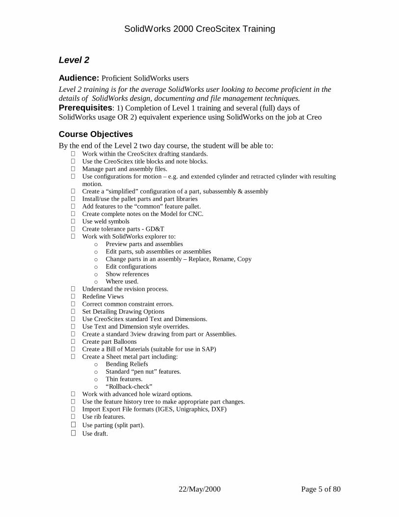
Course Objectives By the end of the Level 2 two day course, the student will be able to: § Work within the CreoScitex drafting standards. § Use the CreoScitex title blocks and note blocks. § Manage part and assembly files. § Use configurations for motion – e.g. and extended cylinder and retracted cylinder with resulting
motion. § Create a “simplified” configuration of a part, subassembly & assembly § Install/use the pallet parts and part libraries § Add features to the “common” feature pallet. § Create complete notes on the Model for CNC. § Use weld symbols § Create tolerance parts - GD&T § Work with SolidWorks explorer to:
o Preview parts and assemblies o Edit parts, sub assemblies or assemblies o Change parts in an assembly – Replace, Rename, Copy o Edit configurations o Show references o Where used.
§ Understand the revision process. § Redefine Views § Correct common constraint errors. § Set Detailing Drawing Options § Use CreoScitex standard Text and Dimensions. § Use Text and Dimension style overrides. § Create a standard 3view drawing from part or Assemblies. § Create part Balloons § Create a Bill of Materials (suitable for use in SAP) § Create a Sheet metal part including:
o Bending Reliefs o Standard “pen nut” features. o Thin features. o “Rollback-check”
§ Work with advanced hole wizard options. § Use the feature history tree to make appropriate part changes. § Import Export File formats (IGES, Unigraphics, DXF) § Use rib features. § Use parting (split part). § Use draft.

SolidWorks 2000 CreoScitex Training
22/May/2000 Page 6 of 80
Plane Overview You can create planes in a part or assembly. You can use planes to sketch, to create a section view of a model, for a neutral plane in a draft feature, and so on.
To create a construction plane:
1 Click Plane on the Reference Geometry toolbar, or click Insert, Reference Geometry, Plane.
2 Select the type of plane you want to create and click Next.
Offset Plane
To create a plane parallel to a plane or face, offset by a specified distance:
1 Select a plane or a planar face. 2 Specify the offset Distance. 3 Select the Reverse Direction check box, if necessary. 4 Click Finish.
Plane 4 is offset from Plane 2. Because the model is drafted, a plane must be created for the sketch of a hole.
The hole is cut in the top of the model.
SolidWorks 2000 CreoScitex Training
22/May/2000 Page 7 of 80
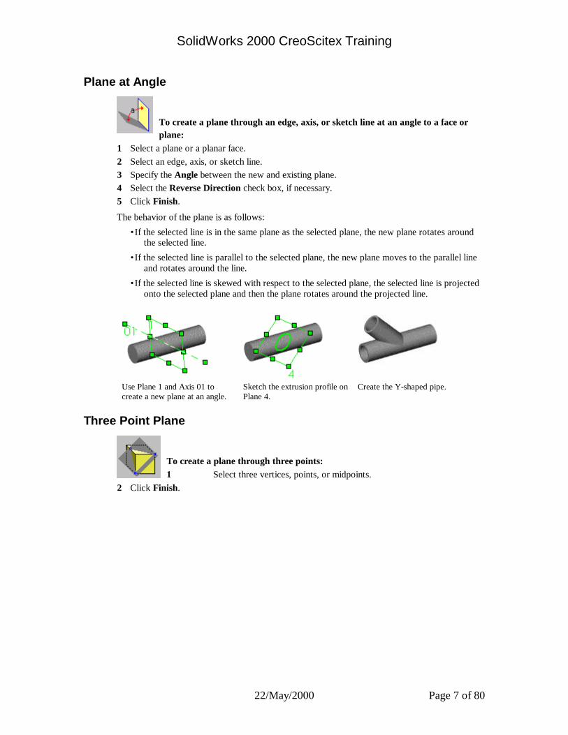
Plane at Angle
To create a plane through an edge, axis, or sketch line at an angle to a face or plane:
1 Select a plane or a planar face. 2 Select an edge, axis, or sketch line. 3 Specify the Angle between the new and existing plane. 4 Select the Reverse Direction check box, if necessary. 5 Click Finish.
The behavior of the plane is as follows:
•If the selected line is in the same plane as the selected plane, the new plane rotates around the selected line.
•If the selected line is parallel to the selected plane, the new plane moves to the parallel line and rotates around the line.
•If the selected line is skewed with respect to the selected plane, the selected line is projected onto the selected plane and then the plane rotates around the projected line.
Use Plane 1 and Axis 01 to create a new plane at an angle.
Sketch the extrusion profile on Plane 4.
Create the Y-shaped pipe.
Three Point Plane
To create a plane through three points: 1 Select three vertices, points, or midpoints.
2 Click Finish.

SolidWorks 2000 CreoScitex Training
22/May/2000 Page 8 of 80
Parallel Plane at Point
To create a plane through a point parallel to a plane or face: 1 Select a plane or planar face and a vertex, point, or midpoint.
2 Click Finish.
Plane 4 is parallel to Plane 2 at the endpoint of the guide curve sketch.
The two loft profiles are sketched on Plane 4.
The lofted cut (shown in blue) is added to the model.
Line and Point Plane
To create a plane through an edge, axis, or sketch line and a point:
1 Select an edge, axis or sketch line and a vertex, a point, or a midpoint. 2 Click Finish.
SolidWorks 2000 CreoScitex Training
22/May/2000 Page 9 of 80
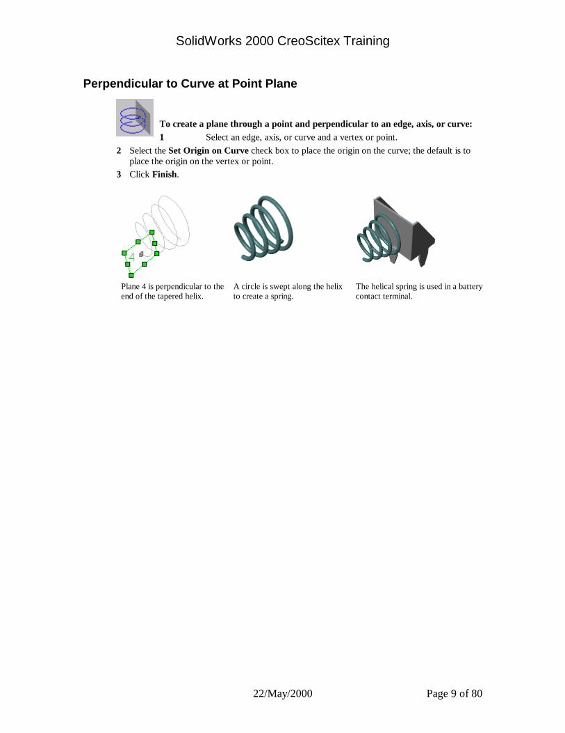
Perpendicular to Curve at Point Plane
To create a plane through a point and perpendicular to an edge, axis, or curve: 1 Select an edge, axis, or curve and a vertex or point.
2 Select the Set Origin on Curve check box to place the origin on the curve; the default is to place the origin on the vertex or point.
3 Click Finish.
Plane 4 is perpendicular to the end of the tapered helix.
A circle is swept along the helix to create a spring.
The helical spring is used in a battery contact terminal.

SolidWorks 2000 CreoScitex Training
22/May/2000 Page 10 of 80
File Locations Lets you specify and locate referenced documents. Folders are searched in the order in which they are listed in the Show folders for list.
To display File Locations: 1 Click Tools, Options, System Options. 2 On the System Options tab, click File Locations.
The Show folders for box displays search paths for files of various types, including: • Referenced Documents • Palette features • Palette parts • Palette forming tools • Blocks • Document Templates • Sheet Format
If one or more folders are displayed in the Folders list, you can Add new folders, Delete existing folders, and Move Up or Move Down to change the search order.
To add a folder: 1 Select a folder type from the Show folder for list. 2 Click Add to add a new directory path to the list 3 Browse in the Choose Directory dialog box to locate the folder. 4 Click OK to add the folder to the Folders list.
To delete a folder: To delete a directory path from the list, select the path in Folders and click Delete.
To move a folder: To change the order of the list, select the path in Folders and click Move Up or Move Down
as needed. NOTE: The paths for Referenced Documents are searched only if Search document folder list
for external references is selected, in System Options, External References. The paths for Palette parts, Palette features, Palette forming tools, and Blocks are
always searched, whether Search document folder list for external references is selected or not.
SolidWorks 2000 CreoScitex Training
22/May/2000 Page 11 of 80
Palette Features and Library Features - Similarities and Differences
Similarities between palette features and library features:
q You create a palette feature in the same way as a library feature.
q The palette feature is displayed as a library feature in the FeatureManager design tree of the target part.
q You can dissolve a palette feature the same way as a library feature.
Differences between palette features and library features:
q When you add a palette feature to a part, you can simply drag the feature roughly where you want it to be, then place it precisely by re-attaching and modifying any locating dimensions saved in the feature.
q You can edit the dimensions of the palette feature as you insert it into the part.
q Not all library features are suitable for use in the Feature Palette window. A palette feature is limited to one mandatory reference (one face, plane, edge, or vertex) on the target part. See Mandatory References .
q Library features that have multiple mandatory references (such as draft features that depend on the selection of several faces) cannot be added through the Feature Palette window.
You can also use the Feature Palette window to add parts to an assembly. You can organize parts in logical groups, and you can see a miniature graphical view of each palette part.
You can add fittings to piping assemblies by dragging them from the Feature Palette window. For more information, see SolidWorks Piping Help Topics.
The Feature Palette window is also used to apply forming tools to sheet metal parts. Forming tools are special parts that punch, stretch, or shape the sheet metal part, to create embossments, lances, flanges, louvers, ribs, and so on.
SolidWorks 2000 CreoScitex Training
22/May/2000 Page 12 of 80
Mandatory References A palette feature is limited to one mandatory reference on the target part.
The limitation of a single mandatory reference does not mean that a palette feature can consist of only one feature. As long as the parent feature uses a single reference, the palette feature can include multiple child features. To examine the parent/child relationships, right-click the feature, and select Parent/Child.
To determine if a library feature is suitable for use in the Feature Palette, insert it as a library feature in a target part (see Adding a Library Feature to a Part). If there is only one mandatory reference listed, you can use the library feature as a palette feature.
Feature Limitations
Because of the limitation of a single reference, lofts, sweeps, and shape features are allowed only in certain cases:
•For lofts, the single mandatory reference is the sketch plane of one of the profiles. This must be the face or plane where you drop the feature. Additional sketch planes must be offset from this plane, or from each other. The library feature must include the planes.
•For sweeps, the sweep path is the single mandatory reference. This must be a model edge. The sketch plane for the sweep section must be a Perpendicular to Curve plane, with the model edge as the curve (when you select the edge, click near the vertex where the plane should be placed). Include this plane in the library feature. Then, when you drop the palette feature in the target part, drop it on the edge that is the sweep path, near the appropriate vertex.
•For shape features, the shape must not be constrained to any entities. The definition can include only variations in Pressure, Bend, and Stretch (on the Controls tab of the Shape Feature dialog box).

SolidWorks 2000 CreoScitex Training
22/May/2000 Page 13 of 80
Add Configuration/Configuration Properties 1 Enter a name for the configuration in the Configuration Name box. The name must not
include the forward slash (/) or at (@) character. A warning message appears when you close the dialog box if the name field contains either of these characters, if the field is blank, or if the name already exists.
2 Enter a Comment that describes the configuration. (Optional) 3 Select Properties for newly inserted items. These options control what happens when new items are added to another configuration, and
then this configuration is activated again. They apply only to assembly configurations:
•Suppress features and mates. When checked, new mates and features added to other configurations are suppressed in this configuration. Otherwise, new mates and features are unsuppressed in this configuration also.
•Suppress component models. When checked, new components added to other configurations are suppressed in this configuration. Otherwise, new components are resolved in this configuration also.
•Hide component models. When checked, new components added to other configurations are hidden in this configuration. Otherwise, new components are shown in this configuration also.
This item applies only to part configurations:
•Suppress Features. By default, newly added features are unsuppressed in the active configuration. This option controls what happens when new features are added to another configuration, then this configuration is activated again. When checked, new features added to other configurations are suppressed in this configuration. Otherwise, new features are unsuppressed in this configuration also.
4 Select the way properties are applied (only for assemblies):
•Apply properties to sub-assembly root only. When selected, the properties chosen above apply to the sub-assembly root only.
•Apply properties to ALL sub-assembly components. When selected, the properties chosen above apply to all components in the sub-assembly. (Use this option when you want to hide or suppress most of the components in a large assembly. You can then individually select the components that you want unsuppressed or visible.)
5 Click Advanced to specify how the assembly or part is listed in a Bill of Materials. 6 Click Custom to access the Summary Info dialog box.
7 To specify a color for the configuration, select the Use configuration specific color check box, then click Color to specify a color from the color palette for the configuration.
If the color for wireframe and HLR modes is the same as the color for shaded mode, the configuration specific color applies to all three modes. If the color is not the same for all three modes, then the configuration specific color applies to shaded mode only. To be sure the colors are the same for the three modes, select the Apply same color to wireframe, HLR and shaded check box in Tools, Options, Document Properties, Colors.
8 Click OK. The new configuration name appears in the tree. 9 Change the model as needed to create the design variation.
•In a part, you can suppress features, modify dimensions, add custom properties, and so on.
•In an assembly, you can suppress or hide components, choose a different referenced configuration of components, and so on.
SolidWorks 2000 CreoScitex Training
22/May/2000 Page 14 of 80
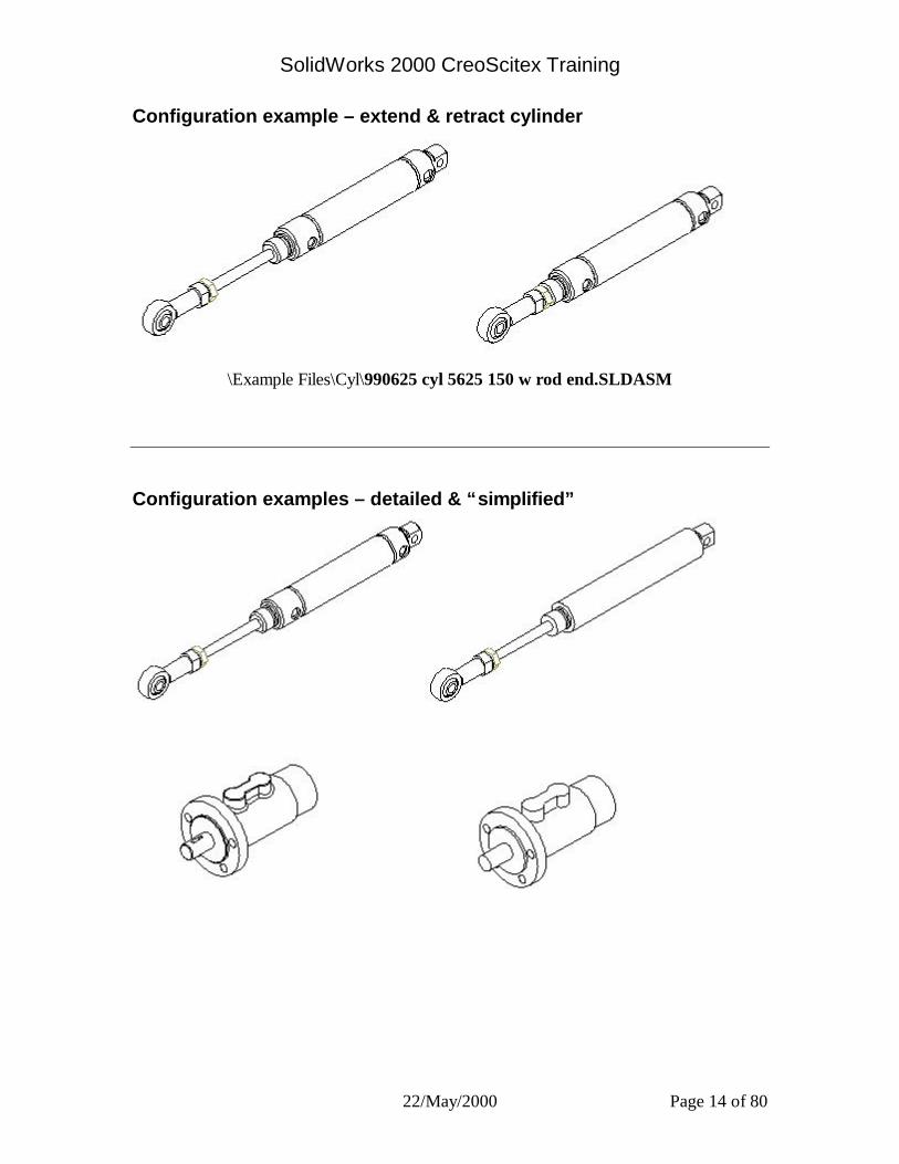
Configuration example – extend & retract cylinder
\Example Files\Cyl\990625 cyl 5625 150 w rod end.SLDASM
Configuration examples – detailed & “simplified”
SolidWorks 2000 CreoScitex Training
22/May/2000 Page 15 of 80
Suppress and Unsuppress Features
To suppress a feature: 1 Select the feature in the FeatureManager design tree, or select a face of the feature in the
graphics area. To select multiple features, hold down Ctrl as you select.
2 Click Suppress on the Features toolbar, or click Edit, Suppress. - or - 1 In the FeatureManager design tree, right-click a feature, and select Properties. 2 In the Feature Properties dialog box, select the Suppressed check box, and click OK. The selected feature is removed from the model (but not deleted). The feature disappears
from the model view and is shown in gray in the FeatureManager design tree.
To unsuppress a feature: 1 Select the suppressed feature in the FeatureManager design tree.
2 Click Unsuppress on the Features toolbar, or click Edit, Unsuppress. - or - 1 In the FeatureManager design tree, right-click a feature, and select Properties. 2 In the Feature Properties dialog box, clear the Suppressed check box, and click OK. If you want to unsuppress a suppressed feature, you must select it using the FeatureManager
design tree.
To unsuppress a feature and its dependents: 1 Select the suppressed parent feature in the FeatureManager design tree.
2 Click Unsuppress with Dependents on the Features toolbar, or click Edit, Unsuppress with Dependents.
The selected feature and any features that are dependent on it are returned to the model. - or - 1 Select the child feature in the FeatureManager design tree.
2 Click Unsuppress with Dependents on the Features toolbar, or click Edit, Unsuppress with Dependents.
The selected feature and its parent feature are returned to the model.
SolidWorks 2000 CreoScitex Training
22/May/2000 Page 16 of 80
Managing part and assembly files.
Simplifying Large Assemblies Large assemblies can consist of hundreds of components. You can simplify a complex assembly by toggling the visibility of the components, and by changing the suppression state of components.
There are several reasons to simplify an assembly:
q To improve system performance, and to reduce rebuild times, especially with very large assemblies.
q To create simplified views of the assembly that include certain components, and exclude others.
q To create design variations of the assembly, with different combinations of components, and different configurations of the components themselves.
Lightweight Parts You can load an assembly with its active parts fully resolved or lightweight.
•When a part is fully resolved, all its model data is loaded in memory.
•When a part is lightweight, only a subset of its model data is loaded in memory. The remaining model data is loaded on an as-needed basis.
You can improve performance of large assemblies significantly by using lightweight parts. Loading an assembly with lightweight parts is faster than loading the same assembly with fully resolved parts.
Lightweight parts are efficient because the full model data for the parts is loaded only as it is needed. Only parts that you select, and parts that are affected by changes that you make in the current editing session, become fully resolved.
Assemblies with lightweight parts rebuild faster because less data is evaluated. Mates on a lightweight part are solved, and you can edit existing mates.
To enable lightweight loading of parts: 1 Click Tools, Options. On the System Options tab, click Performance. 2 Under Assemblies, click the Automatically load parts lightweight check box. NOTE: You can only change this option when no assemblies, or drawings of assemblies, are
open.
When this option is selected, all parts are loaded lightweight when you open an assembly. The only exception is that any parts that are included in the feature scope of assembly feature are always loaded fully resolved. Sub-assemblies themselves are not loaded lightweight, but the individual parts that they contain are lightweight.
When you point at a lightweight part in the graphics area, a feather pointer is displayed, and the body is surrounded by a bounding box. NOTE: Lightweight parts are only used when the model is in Shaded mode. If the model was
last saved in Hidden Lines Removed, Hidden In Gray, or Wireframe mode, lightweight parts are not used.
SolidWorks 2000 CreoScitex Training
22/May/2000 Page 17 of 80
Assembly Features While in an assembly, you can create cut or hole features that exist in the assembly only. You
determine which parts you want the feature to affect by setting the scope. You can create a pattern of assembly features in the same manner as you create a pattern of features in a part.
This is useful for creating cuts or holes that are added after the components are actually assembled, and that affect more than one component. When you want to add a cut or hole to a single component in an assembly, it is better to edit the part in context than to use an assembly feature.
While it is not a requirement, it is good practice to fully define the positions of the components of the assembly, or fix their locations before you add assembly features. This helps prevent unexpected results if the components are moved later.
Replacing a Single Instance of an Assembly Component You can replace only the selected instance of a component.
To replace a single instance of a component by editing its properties: 1 In the FeatureManager design tree or the graphics area, right-click the component you want
to replace, and select Component Properties. 2 Enter a Component Name if you want the FeatureManager design tree to list the component
by a name that is different from the name of the component file. If the Component Name box is unavailable, click Tools, Options. On the System Options
tab, under External References, clear the Update component names when documents are replaced check box.
The Component Name is used in the FeatureManager design tree only; the component’s file name does not change. Component names may not include the forward slash (/) or at (@) characters.
3 To locate the replacement component, click Browse. Navigate to the new document. If desired, click the Preview check box to view the component in the Preview window.
4 Click Open. The Model Document Path displays the selected document name. 5 Click OK to replace the component. The last saved or in-use configuration of the selected component is used.

SolidWorks 2000 CreoScitex Training
22/May/2000 Page 18 of 80
Preserving Mates with Component Replacement When replacing a component, mates used in the original part are applied to the replacement part wherever possible. Preservation of mates depends on the entities used in the mates being the same. If the entities used in the mates are not the same, or do not exist, in the replacement part, the mates will have an error.
You can rename the corresponding edges and/or faces on a replacement part to match the edge/face names on the original part to ensure that the mates are preserved.
To manually name the entities used in a mate: 1 In the original part document, right-click the entity used in the mate, and select Face
Properties (or Edge Properties). 2 Under Entity Information, enter a new Name, and click OK. 3 In the replacement part document, right-click the corresponding edge or face, and edit the
entity properties, using the same Name. TIP: To automatically name the entities used in a mate, click the Automatically generate
names for referenced geometry check box on the External References Options dialog box.
To identify named entities: 1 In the part document, right-click the part icon at the top of the FeatureManager design tree,
and select List Named Entities (if the part has no named entities, the shortcut menu does not include this selection.)
2 To highlight a named entity, click the item in the Named Entities dialog box.
What's Wrong? Lets you view any rebuild errors of a part or assembly. A down arrow appears next to the name of the part or assembly, and the name of the failed feature. An exclamation mark indicates the item responsible for the error.
Right-click the sketch, feature, part, or assembly name and select What’s Wrong to display the error.
Some common rebuild errors include:
•Dangling Dimensions or Relations - dimensions or relations to an entity that no longer exists
•Features that cannot be rebuilt, such as a fillet that is too large
If an error message has a prefix of **, you can click on the error message and the problem area is highlighted on the model.
You can turn off the automatic display of errors by clearing the Display Errors at Every Rebuild check box. NOTE: The Display Errors at Every Rebuild check box affects only the current session.
Select the Display Full message check box if you want the complete message displayed whenever there is an error. Otherwise, an abbreviated message is displayed. (The default is Display Full message.)
The Rebuild Errors dialog box is displayed when the error is first generated, or you can display the dialog box at any time by right-clicking on the part in the FeatureManager design tree.

SolidWorks 2000 CreoScitex Training
22/May/2000 Page 19 of 80
Alternative Method for Editing an Exploded View
To edit an exploded view without the Assembly Exploder dialog box: 1 Double-click the ExplView feature in the ConfigurationManager to explode the view. 2 Right-click the component you want to reposition, and select Show Explode Steps. You can
right-click the component in the graphics area, or you can switch to the FeatureManager, then right-click the component in the tree.
The drag handles for the explode steps on the selected component are displayed.
3 Drag the component by the green drag handle to the new position. 4 Repeat as needed for each component, then collapse the assembly.
SolidWorks 2000 CreoScitex Training
22/May/2000 Page 20 of 80
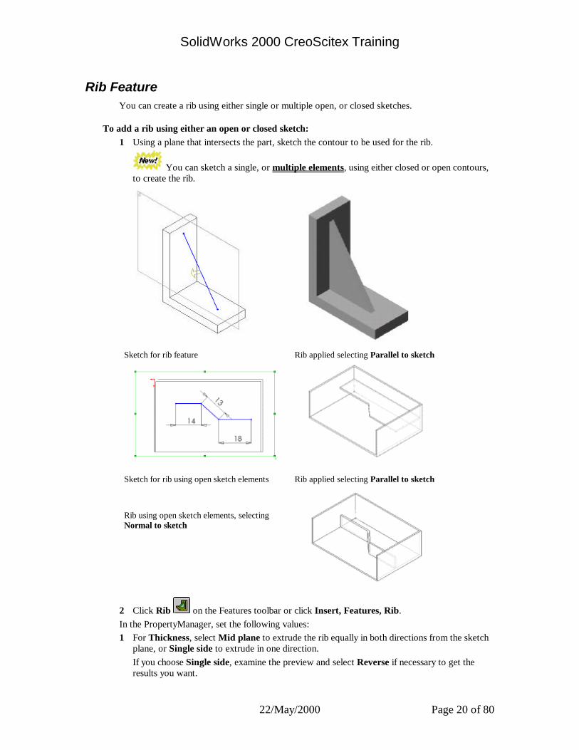
Rib Feature You can create a rib using either single or multiple open, or closed sketches.
To add a rib using either an open or closed sketch: 1 Using a plane that intersects the part, sketch the contour to be used for the rib.
You can sketch a single, or multiple elements, using either closed or open contours, to create the rib.
Sketch for rib feature Rib applied selecting Parallel to sketch
Sketch for rib using open sketch elements Rib applied selecting Parallel to sketch Rib using open sketch elements, selecting Normal to sketch
2 Click Rib on the Features toolbar or click Insert, Features, Rib. In the PropertyManager, set the following values: 1 For Thickness, select Mid plane to extrude the rib equally in both directions from the sketch
plane, or Single side to extrude in one direction. If you choose Single side, examine the preview and select Reverse if necessary to get the
results you want.
SolidWorks 2000 CreoScitex Training
22/May/2000 Page 21 of 80
2 Enter the thickness of the rib, or click the arrows to change the value. 3 For Extrusion Direction, select Parallel to sketch to extend parallel to the sketch, along the
plane, or Normal to sketch to follow the direction of the sketch. Note the direction of the preview arrow, and click the Flip material side check box, if
necessary. 4 For Extension Type, select Natural to follow the curve in the sketch of the rib or Linear, to
extend in a linear fashion from the sketch of the rib. NOTE: If you select Parallel to sketch as the Extrusion Direction, you can only select
Natural as an Extension Type. 5 To add a draft, select Enable draft in Draft conditions, and enter the draft Angle or click
the arrows to change the value. 6 Select Draft outward if necessary. 7 To create a rib with multiple drafts using draft angles, click Next Reference until the arrow
shows on the contour from which you want to start the draft angle. Enter a draft angle for the first contour, and click Next Reference to proceed to the next
contour. 8 Repeat until you have selected all the contours and applied a draft Angle to each. 9 Click OK.
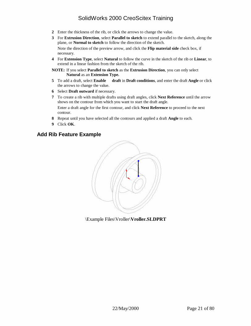
Add Rib Feature Example
\Example Files\Vroller\Vroller.SLDPRT
SolidWorks 2000 CreoScitex Training
22/May/2000 Page 22 of 80
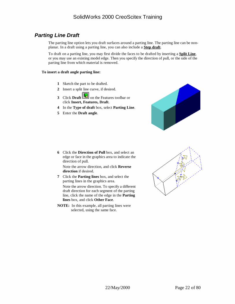
Parting Line Draft The parting line option lets you draft surfaces around a parting line. The parting line can be non-planar. In a draft using a parting line, you can also include a Step draft.
To draft on a parting line, you may first divide the faces to be drafted by inserting a Split Line, or you may use an existing model edge. Then you specify the direction of pull, or the side of the parting line from which material is removed.
To insert a draft angle parting line:
1 Sketch the part to be drafted. 2 Insert a split line curve, if desired.
3 Click Draft on the Features toolbar or click Insert, Features, Draft.
4 In the Type of draft box, select Parting Line. 5 Enter the Draft angle.
6 Click the Direction of Pull box, and select an
edge or face in the graphics area to indicate the direction of pull.
Note the arrow direction, and click Reverse direction if desired.
7 Click the Parting lines box, and select the parting lines in the graphics area.
Note the arrow direction. To specify a different draft direction for each segment of the parting line, click the name of the edge in the Parting lines box, and click Other Face.
NOTE: In this example, all parting lines were selected, using the same face.
SolidWorks 2000 CreoScitex Training
22/May/2000 Page 23 of 80
Thin Feature The thin features dialog box lets you define the characteristics of extruded thin features.
• Type. Type lets you specify whether to extrude the thin feature in One Direction, Mid-plane, or Two Directions.
• Wall Thickness. Use the spin box to specify the thickness of the thin feature wall.
• Reverse. Lets you reverse the extrusion of the wall thickness.
• Link to Thickness. Ensures that the boss is the same thickness as the base.
If you created a closed profile you can select the following options: • Cap Ends. Specifies that the ends of the thin feature are capped. A capped thin
feature must be extruded from a closed profile sketch. When the ends are capped, all walls of the feature are closed; the center is hollow.
• Cap Thickness. Lets you specify the thickness of the cap. (Available only if Cap Ends is selected.)
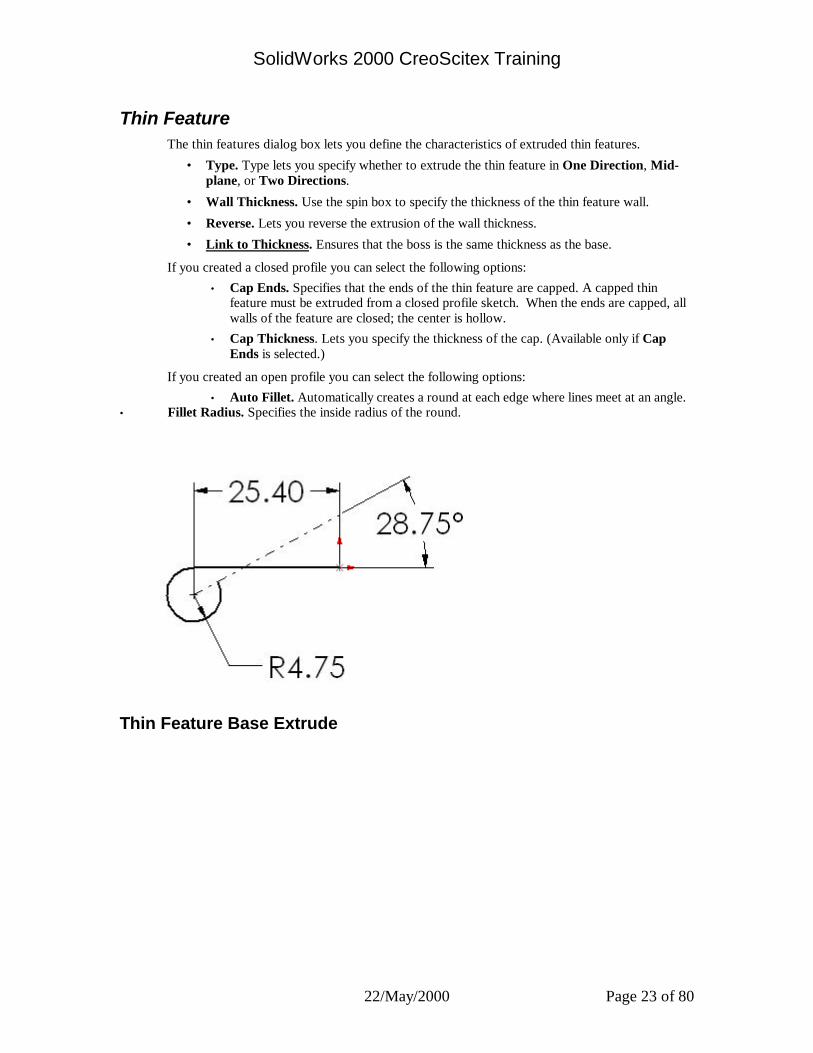
If you created an open profile you can select the following options: • Auto Fillet. Automatically creates a round at each edge where lines meet at an angle.
• Fillet Radius. Specifies the inside radius of the round.
Thin Feature Base Extrude

SolidWorks 2000 CreoScitex Training
22/May/2000 Page 24 of 80
Extrude Midplane 102
Extrude Cut Feature
Extrude Cut Feature
SolidWorks 2000 CreoScitex Training
22/May/2000 Page 25 of 80
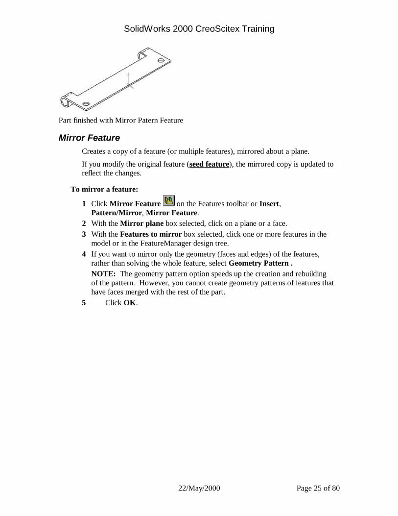
Part finished with Mirror Patern Feature
Mirror Feature Creates a copy of a feature (or multiple features), mirrored about a plane.
If you modify the original feature (seed feature), the mirrored copy is updated to reflect the changes.
To mirror a feature:
1 Click Mirror Feature on the Features toolbar or Insert, Pattern/Mirror, Mirror Feature.
2 With the Mirror plane box selected, click on a plane or a face. 3 With the Features to mirror box selected, click one or more features in the
model or in the FeatureManager design tree. 4 If you want to mirror only the geometry (faces and edges) of the features,
rather than solving the whole feature, select Geometry Pattern . NOTE: The geometry pattern option speeds up the creation and rebuilding of the pattern. However, you cannot create geometry patterns of features that have faces merged with the rest of the part.
5 Click OK.

SolidWorks 2000 CreoScitex Training
22/May/2000 Page 26 of 80
Sheet Metal Sheet metal parts are generally used as enclosures for components or to provide support to other components.
You can design a sheet metal part on its own without any references to the parts it will enclose, or you can design the part in the context of an assembly containing the enclosed components.
This chapter introduces the SolidWorks sheet metal functionality and describes:
q Designing sheet metal parts
q Rolling back and rebuilding sheet metal designs
q Creating sheet metal parts
q Adding and editing bends
q Selecting the type of bend allowance
q Adding and editing auto reliefs
q Adding features in the flattened state
q Creating rips
q Creating hems
q Creating bends across multiple tabs
q Creating flat pattern configurations
q Creating sheet metal drawings
q Creating forming tools

SolidWorks 2000 CreoScitex Training
22/May/2000 Page 27 of 80
Bend Allowance Options
Bend Table A sample bend table for sheet metal operations is provided in <install_dir>\lang\english\sample.btl. To use your own bend table, copy and edit this bend table using any text editor, to specify your required bend allowances.
NOTE: Bend table units must be specified in meters. The sample bend table is provided only
for informational purposes. The values in this table do not represent any actual bend allowance values. If the thickness of the part or bend angle falls between values in the table, the software interpolates the values to calculate the bend allowance.

SolidWorks 2000 CreoScitex Training
22/May/2000 Page 28 of 80
K-factor K-factor is a ratio that represents the location of the neutral sheet with respect to the thickness of the sheet metal part.
Bend allowance using a K-factor is calculated as follows: BA=Π(R + KT) A/180 where: BA = bend allowance R = inside bend radius K = K factor, which is t / T T = material thickness t = distance from inside face to neutral sheet A = bend angle in degrees (the angle through which the material is bent)
Bend Allowance Value You can specify an explicit bend allowance for any sheet metal bend by entering the value when you create the bend.
Note: For a given bend radius and angle, the specified value for the bend allowance should be between the length of the inner edge and the length of the outer edge of the bend.

SolidWorks 2000 CreoScitex Training
22/May/2000 Page 29 of 80
Sheet Metal Features
FeatureManager Design Tree
When you click Insert Bends or Insert, Features, Sheet Metal, Bends, two distinct stages are applied to the sheet metal part.
•The part is flattened and a bend allowance is added. The developed length is calculated, based on the bend radius and bend allowance.
•The flattened part is restored to the folded state to create the formed, folded version of the part.
Three new features and icons appear on the FeatureManager design tree that are specific to sheet metal operations. These features are:
•Sheet-Metal
•Flatten-Bends
•Process-Bends
These three features represent a process plan for the sheet metal part.
Sheet-Metal contains the definition of the sheet metal part. This feature stores the default bend parameter information (thickness, bend radius, bend allowance, auto relief ratio, and fixed entity) for the entire part.
Flatten-Bends represents the flattened part. This feature contains information related to the conversion of sharp and filleted corners into bends. Each bend generated from the model is listed as a separate feature under Flatten-Bends. Bends generated from filleted corners, cylindrical faces, and conical faces are listed as Round-Bends; bends generated from sharp corners are listed as Sharp-Bends. The Sharp-Sketch listed under Flatten-Bends is the sketch that contains the bend lines of all sharp and round bends generated by the system. This sketch cannot be edited but can be hidden or shown.
Process-Bends represents the transformation of the flattened part into the finished, formed part. Bends created from bend lines specified in the flat are listed under this feature. FlatSketch, listed under Process-Bends, is a placeholder for these bend lines. This sketch can be edited, hidden, or shown. Features that are listed after the Process-Bends icon in the FeatureManager design tree do not appear in the flattened view of the part. You flatten the view of the part by rolling back the FeatureManager design tree to before the Process-Bends feature.

SolidWorks 2000 CreoScitex Training
22/May/2000 Page 30 of 80
Rollback Bar Reverts the model to an earlier state, suppressing recently added features. You can add new features or edit existing features while the model is in the rolled-back state.
You can roll back a part using the Rollback Bar in the FeatureManager design tree. The rollback bar is a wide yellow line which turns blue when selected. Drag the bar up or down the FeatureManager design tree to step forward or backward through the regeneration sequence.
You can use the Rollback Bar to flatten sheet metal bends, or you can click Flattened to flatten. See also Rolling Back and Rebuilding Sheet Metal Parts.
To revert a part to an earlier state: 1 Place your cursor over the rollback bar in the FeatureManager design tree. The cursor
changes to a hand. 2 Click to select the rollback bar. The bar changes color from yellow to blue. 3 Drag the rollback bar up the FeatureManager design tree until it is above the feature(s) you
want rolled back, - or - Click in the FeatureManager tree and use the up and down arrow keys on the keyboard to
move the rollback bar up or down. TIP: To enable this use of the arrow keys, click Tools, Options, and on the System Options
tab, select FeatureManager. Select the Arrow key navigation check box. 4 To roll forward again, drag the rollback bar to the bottom of the FeatureManager design tree. NOTE: The FeatureManager icons are gray and unavailable after they are rolled back.

SolidWorks 2000 CreoScitex Training
22/May/2000 Page 31 of 80
Edit Bends You can edit bend information by using the Edit Definition option from the right-mouse menu. The scope of the changes depends upon which feature is edited. For more information, select from the following: q Edit a single bend. q Edit bends for an entire part. q Edit bends listed under Flatten-Bends. q Edit bends listed under Process-Bends.
NOTE: You cannot change the bend angle for sharp bends because this is calculated from your model. You cannot change the bend angle and radius for round bends. The bend angle is calculated from the model and the bend radius is specified in the sketch or in the fillet.
You must use a solid sketch Line to add a bend to a flattened sheet metal part. You can not add a bend
using a Centerline .
Edit a Single Bend
To edit a single bend: 1 In the FeatureManager design tree, right-click a SharpBend, RoundBend, or FlatBend item
that you want to change, and select Edit Definition. 2 In the dialog box that comes up, make changes as needed to the bend Radius, Angle, or
Order. Click Bend Down to reverse the direction of the bend. 3 In the Bend Allowance section, you can click to clear the Use Default checkbox if you want
to change the use of the bend table , k-factor, or bend allowance . 4 To change the relief type and size, click the Auto Relief tab. 5 Click to clear Use default relief. 6 Change the type of relief cut in the Relief Type section. 7 If you select Rectangular, change the Width and Depth values in the Relief Size section. 8 Click OK to exit the dialog box and rebuild the part.
SolidWorks 2000 CreoScitex Training
22/May/2000 Page 32 of 80
Edit Bends for Entire Part
To Edit bend parameters for the entire part: 1 In the FeatureManager design tree, right-click the Sheet-Metal feature, and select Edit
Definition. 2 In the Sheet-Metal dialog box, change the Default Bend Radius. 3 Change the Fixed edge or face by selecting a different edge or face on the model. 4 In the Bend allowance section, change the use of the bend table , k-factor, or bend
allowance . 5 To add auto reliefs, select Use auto relief in the Auto Relief section, and select the type of
relief cut. To change the type of auto relief, select a different type of relief cut. 6 If you select Rectangular, you must specify a Relief ratio. 7 Click OK.
Edit Bends Listed Under Flatten-Bends
To edit bend parameters for all bends listed under Flatten-Bends: 1 In the FeatureManager design tree, select the Flatten-Bends feature. 2 Right click and select Edit Definition. 3 In the Flatten-Bends dialog box, clear the Default bend radius. 4 In the Bend allowance region, you can click to clear the Use Default checkbox if you want
to change the use of the bend table , k-factor, or bend allowance . 5 Click OK.
Edit Bends Listed Under Process-Bends
To edit bend parameters for all bends listed under Process-Bends: 1 In the FeatureManager design tree, select the Process-Bends feature. 2 Right-mouse click and select Edit Definition. 3 In the Process-Bends dialog box, change the Default Bend Radius. 4 In the Bend allowance region, you can clear the Use Default checkbox if you want to
change the use of the bend table , k-factor, or bend allowance . 5 Click OK.

SolidWorks 2000 CreoScitex Training
22/May/2000 Page 33 of 80
Adding Walls to a Sheet Metal Part Important: All walls must be in place before the Sheet-Metal feature adds the bends.
It is recommended that you add all the walls as described here, before inserting bends. However, if necessary, you can rollback the model to the last feature before the Sheet-Metal feature to add a wall. Or, if parent-child dependencies allow, you may be able to re-order a wall before the Sheet-Metal feature. NOTE: You cannot add walls to cylindrical or conical faces on sheet metal parts.
To add a wall to a sheet metal part: 1 Open a sketch on the face of the part where the new wall will be attached. 2 Select a linear edge of a planar face on the model to attach the wall to, and click Convert
Entities or Tools, Sketch Tools, Convert Entities. 3 Drag the vertices near existing bends a small distance away from the bends to allow for the
bend radius.
4 Click Extruded Boss/Base or Insert, Boss, Extrude, then set the Type to Blind and specify the Depth.
5 On the Thin Feature tab, set the Wall Thickness to be the same as the base part. 6 Click OK.
7 Click or Insert, Features, Sheet Metal, Bends.
SolidWorks 2000 CreoScitex Training
22/May/2000 Page 34 of 80
Extruding Tabs on a Sheet Metal Part
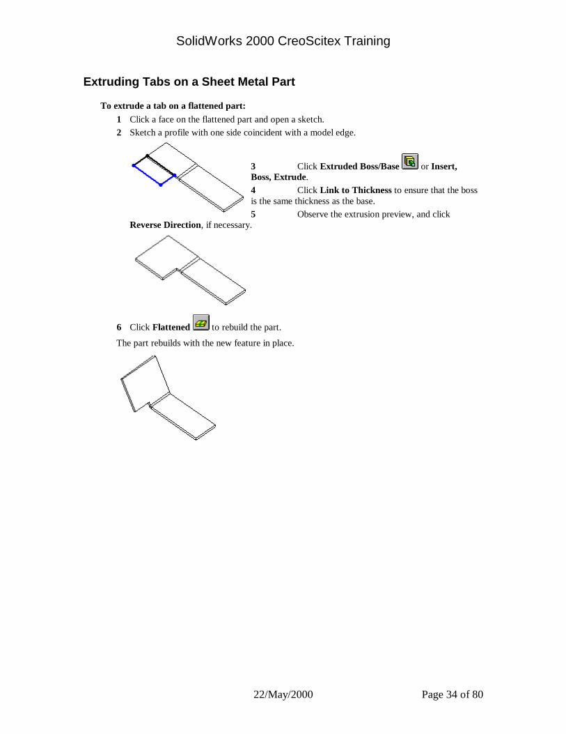
To extrude a tab on a flattened part: 1 Click a face on the flattened part and open a sketch. 2 Sketch a profile with one side coincident with a model edge.
3 Click Extruded Boss/Base or Insert, Boss, Extrude. 4 Click Link to Thickness to ensure that the boss is the same thickness as the base. 5 Observe the extrusion preview, and click
Reverse Direction, if necessary.
6 Click Flattened to rebuild the part.
The part rebuilds with the new feature in place.
SolidWorks 2000 CreoScitex Training
22/May/2000 Page 35 of 80
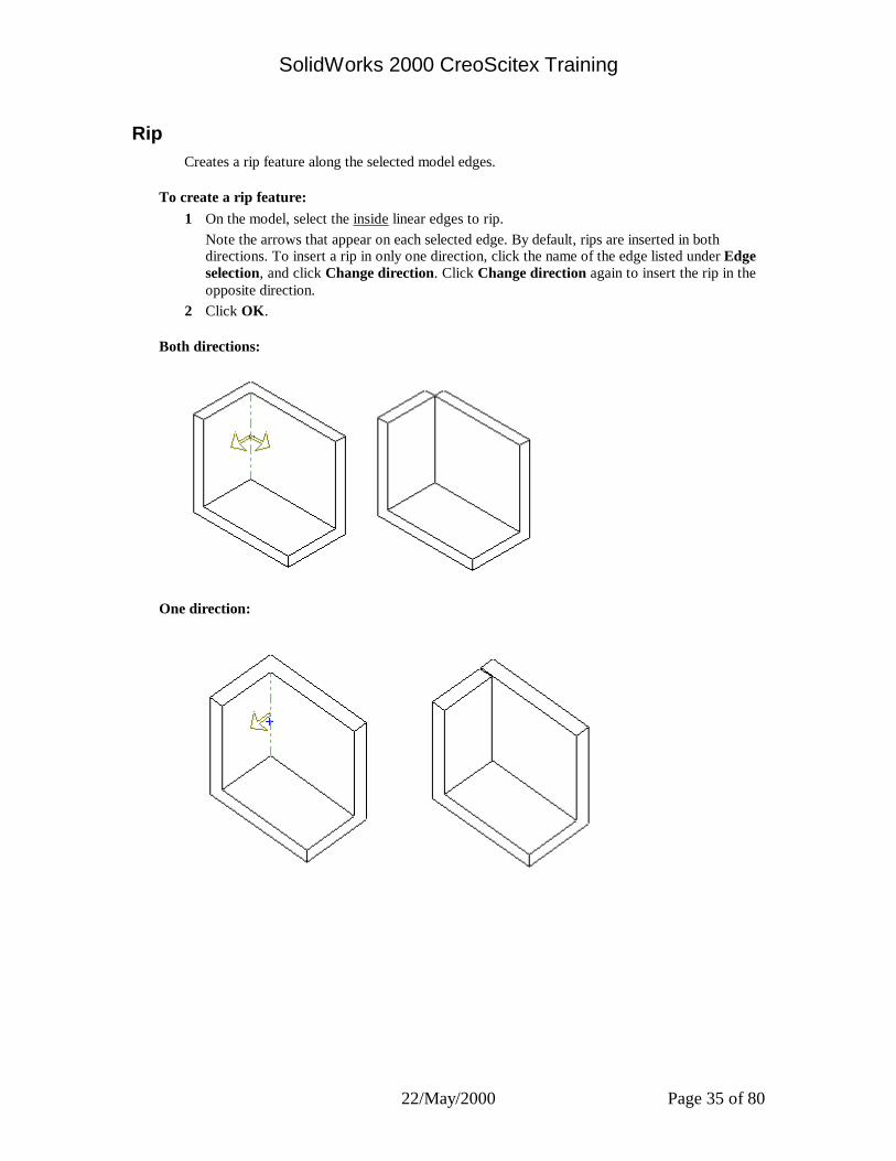
Rip Creates a rip feature along the selected model edges.
To create a rip feature: 1 On the model, select the inside linear edges to rip.
Note the arrows that appear on each selected edge. By default, rips are inserted in both directions. To insert a rip in only one direction, click the name of the edge listed under Edge selection, and click Change direction. Click Change direction again to insert the rip in the opposite direction.
2 Click OK.
Both directions:
One direction:
SolidWorks 2000 CreoScitex Training
22/May/2000 Page 36 of 80
Auto Relief The software automatically adds relief cuts wherever needed when inserting bends if you select Use auto relief. The software supports two types of relief cuts:
•Rectangular
•Tear
If you want to automatically add Rectangular reliefs, you must specify the Relief ratio.
Tear reliefs are of the minimum size required to insert the bend and flatten the part.
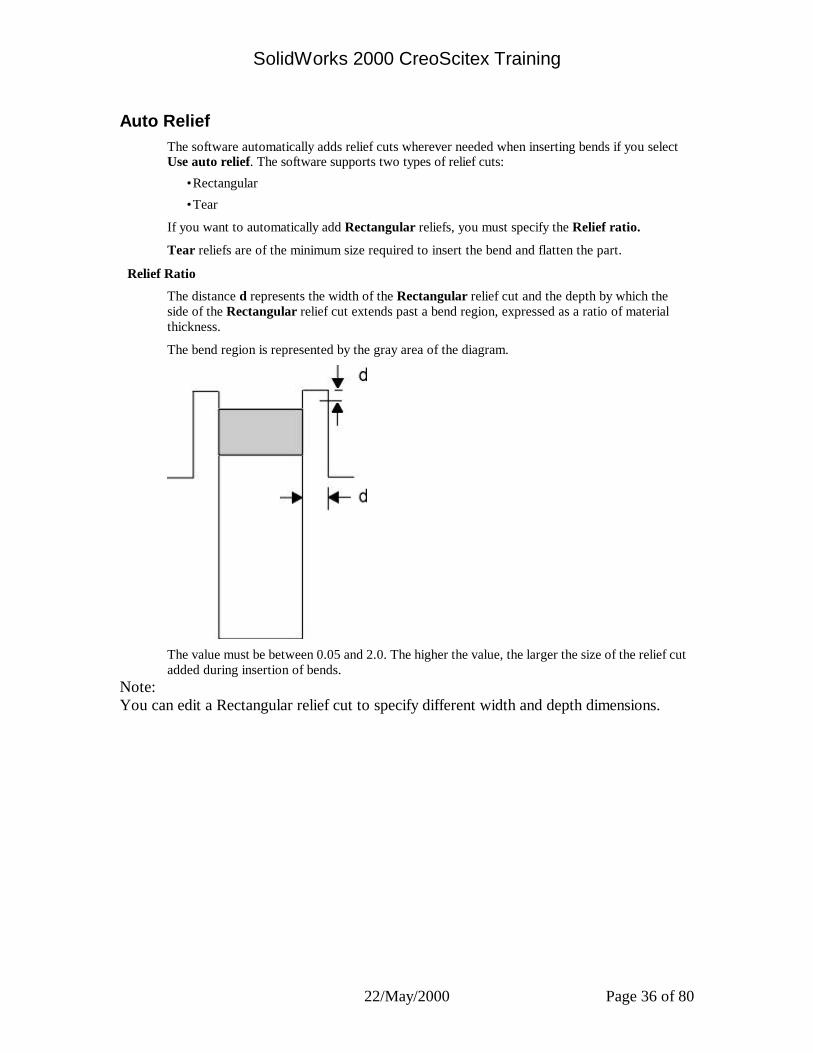
Relief Ratio
The distance d represents the width of the Rectangular relief cut and the depth by which the side of the Rectangular relief cut extends past a bend region, expressed as a ratio of material thickness.
The bend region is represented by the gray area of the diagram.
The value must be between 0.05 and 2.0. The higher the value, the larger the size of the relief cut added during insertion of bends.
Note: You can edit a Rectangular relief cut to specify different width and depth dimensions.
SolidWorks 2000 CreoScitex Training
22/May/2000 Page 37 of 80
Edit a Single Auto Relief You can change the type and size of a relief cut for an individual bend. NOTE: You cannot edit relief cuts in sheet metal parts created in versions prior to SolidWorks
99.
To change the type and size of a relief cut for a single bend: 1 In the FeatureManager design tree, click beside the Flatten-Bends feature. 2 Right-click the bend you want to edit and select Edit Definition. 3 Click the Auto Relief tab. 4 Click to clear Use default relief. 5 Change the type of relief cut in the Relief Type section. 6 If you select Rectangular, change the Width and Depth values in the Relief Size section. 7 Click OK.
Edit All Auto Reliefs You can change the type of auto reliefs automatically added to the bend regions in sheet metal parts.
NOTE: You cannot edit relief cuts in sheet metal parts created in versions prior to SolidWorks 99.
To change the type of relief cut for all bends: 1 Right-click the Sheet-Metal feature in the FeatureManager design tree and select Edit
Definition. 2 In the Auto Relief section, change the type of relief cut. 3 If you select Rectangular, you must specify the Relief ratio. 4 Click OK.

SolidWorks 2000 CreoScitex Training
22/May/2000 Page 38 of 80
Creating Drawings of Sheet Metal Parts You can create drawings of sheet metal parts using either one of the following methods:
•Automatically create the flat pattern configuration of the sheet metal part when you create the drawing.
•Manually create the flat pattern configuration of the sheet metal part, then create the drawing.
To show bend lines in flat pattern view: 1 In the drawing window, expand Drawing View in the FeatureManager design tree to show
the part’s Flatten-Bends and Process-Bends features. Then expand both of these features. 2 Right-click Sharp-Sketch and click Show, then right-click Flat-Sketch and click Show.
To remove the display of the bend region lines: 1 In the drawing window, right-click Drawing View in the FeatureManager design tree, or
right-click the drawing view in the graphics area. 2 Select Tangent Edge, Tangent Edges Removed.
To change the configuration in the drawing view: 1 Right-click the drawing view in which you want to change the configuration, and select
Properties. 2 In the Use named configuration box, select a different configuration and click OK. 3 Right-click the drawing view again, and select Update View, if necessary.

SolidWorks 2000 CreoScitex Training
22/May/2000 Page 39 of 80
Automatic Sheet Metal Drawings
To create a drawing of a flat pattern that the software creates automatically: 1 Create a new drawing document.
2 Click Named View or Insert, Drawing View, Named View. 3 Change to the part window and click anywhere. 4 Select the Flat pattern view from the Drawing View - Named View dialog box, and click
OK. The software creates a flat pattern configuration automatically. 5 Return to the drawing window and click to place the flat pattern view. The bend lines are automatically shown in the flat pattern view; the bend region lines are not
shown.
Multiple collinear edges in the flat pattern configuration are merged into a single linear edge in the drawing.
Manual Sheet Metal Drawings To create a drawing of a flat pattern that you create manually:
1 Create a part configuration of a flat pattern. 2 Create a new drawing.
3 Click Named View or Insert, Drawing View, Named View. 4 Change to the part window and click anywhere. Then select the desired view from the
Drawing View - Named View dialog box, and click OK. 5 Return to the drawing window and click to place the view on the sheet.

SolidWorks 2000 CreoScitex Training
22/May/2000 Page 40 of 80
Notes A note can be free floating or placed with a leader pointing to an item (face, edge, or vertex) in the document. It can contain simple text, symbols, parametric text, and hyperlinks.
To set Note options for the current document, click Tools, Options, Document Properties, Notes.
To create notes:
1 Click Note or Insert, Annotations, Note. The Properties dialog box for Note appears. 2 Type in text and select options as desired. 3 With the dialog box still open, click in the graphics area to place the note.
• Click as many times as necessary to place multiple copies.
•If the note has a leader, click once to place the leader, then click a second time to place the note.
• You can change text and other items in the dialog box for each instance of the note.
•While dragging the note and before placing it, press Ctrl. The note stops moving, but the leader continues, lengthening the leader. While still holding Ctrl, click to place the leader. Click as many times as necessary to place additional leaders. Release Ctrl and click to place the note.
4 Click OK to close the dialog box.
Once you have created a note and closed the dialog box, you can edit the note in place by double-clicking it. You can also edit the note and change its properties by right-clicking the note and selecting Properties. For more information on the options available in the Properties dialog box..
You can add more leaders to an existing note by holding down Ctrl and dragging a leader attachment point.

SolidWorks 2000 CreoScitex Training
22/May/2000 Page 41 of 80
Annotation Properties Lets you select the types of annotations that you want to display and set text scale and other annotations options.
To select the types of annotations to display:
1 In the FeatureManager design tree, right-click the Annotations folder, , and select Details.
2 In the Annotation Properties dialog box, specify a Display Filter by selecting the annotation types to display by default:
Cosmetic threads Geometric tolerances Datums Notes Datum targets Surface finish Feature dimensions Welds Reference dimensions
- or - Select Display all types to show all kinds of annotations available for that part or view.
3 Change the values in the Text scale edit box to change the scale of the text used in the annotations.
4 Select from the following options:
•Always display text at the same size. When checked, all annotations and dimensions are displayed at the same size regardless of zoom. Note that drawings have this option disabled and always zoom the text height.
•Display items only in the view orientation in which they are created. When checked, any annotation is displayed only when the model is viewed in the same orientation as when the annotation was added. Rotating the part or selecting a different view orientation removes the annotation from the display.
•Display annotations / Display assembly annotations. When checked, all annotation types that are selected in the Display filter are displayed. For assemblies, this includes not only the annotations that belong to the assembly, but also the annotations that are displayed in the individual part documents.
•Use assembly’s setting for all components. When checked, the display of all annotations matches the setting for the assembly document, regardless of the setting in the individual part documents. Use this option along with Display assembly annotations to display different combinations of annotations.
•If you use JIS dimensioning standards, specify the JIS surface finish size (1,2,3 characters) or Scale.
5 Click OK to accept your changes; click Cancel to exit the dialog without saving the changes.

SolidWorks 2000 CreoScitex Training
22/May/2000 Page 42 of 80
ANSI Weld Symbol Creates symbols to provide weld specifications on your part, assembly, and drawing documents.
To create a weld symbol: 1 Click an edge in the drawing view where you want to indicate a welded joint.
2 Click Weld Symbol or Insert, Annotations, Weld Symbol. The ANSI Weld Symbol dialog box appears. The symbol is displayed in the preview box as you select symbols and add appropriate
dimensions and values. 3 In the boxes beside the Weld Symbol button, enter the weld dimensions. 4 Click the Weld Symbol button and select a symbol type from the list of standard symbols.
5 For a second fillet, select the 2nd fillet check box and enter the weld dimensions in the boxes beside the check box.
The 2nd fillet is available for only certain weld symbols (Square or Bevel, for example). 6 Specify other options as needed, such as Finishing Method, Contour, Joint with Spacer,
Groove angle, or Root opening. For Root opening, you can select the Inside check box, the Arrow check box, or neither.
7 Select check boxes for All around, Field or site weld, Display pointing down, or Stagger weld as needed.
8 To specify the welding process, click Specification process and enter the text in the box. 9 Choose whether the weld is to be applied to the object on the Arrow Side or the Other side. 10 Choose a Leader Anchor style.
11 If you are in a drawing with more than one layer, you can choose a named layer from the Layer list.
12 Click OK.
SolidWorks 2000 CreoScitex Training
22/May/2000 Page 43 of 80
Geometric Tolerancing The SolidWorks software supports the ANSI Y14.5 Geometric and True Position Tolerancing guidelines.
•You can place geometric tolerancing symbols, with or without leaders, anywhere in a
drawing, part, assembly, or sketch, and you can attach it anywhere on a dimension line.
•The pointer changes to when it is near the handle of an arrow of a geometric tolerancing symbol on a dimension.
•You can add multiple symbols without closing the dialog box, and you can display multiple perpendicular leaders.
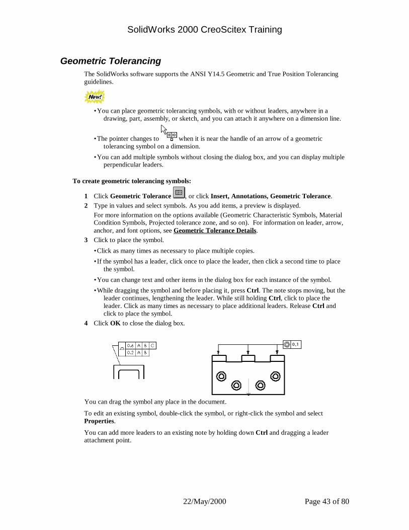
To create geometric tolerancing symbols:
1 Click Geometric Tolerance , or click Insert, Annotations, Geometric Tolerance. 2 Type in values and select symbols. As you add items, a preview is displayed. For more information on the options available (Geometric Characteristic Symbols, Material
Condition Symbols, Projected tolerance zone, and so on). For information on leader, arrow, anchor, and font options, see Geometric Tolerance Details.
3 Click to place the symbol.
•Click as many times as necessary to place multiple copies.
•If the symbol has a leader, click once to place the leader, then click a second time to place the symbol.
•You can change text and other items in the dialog box for each instance of the symbol.
•While dragging the symbol and before placing it, press Ctrl. The note stops moving, but the leader continues, lengthening the leader. While still holding Ctrl, click to place the leader. Click as many times as necessary to place additional leaders. Release Ctrl and click to place the symbol.
4 Click OK to close the dialog box.
You can drag the symbol any place in the document.
To edit an existing symbol, double-click the symbol, or right-click the symbol and select Properties.
You can add more leaders to an existing note by holding down Ctrl and dragging a leader attachment point.

SolidWorks 2000 CreoScitex Training
22/May/2000 Page 44 of 80
First Angle and Third Angle Projection In third angle projection, the default front view from the part or assembly is displayed at the lower left. In first angle projection, the front view is displayed at the upper left. For information about setting the default projection:
3rd Angle Projection 1st Angle Projection
SolidWorks 2000 CreoScitex Training
22/May/2000 Page 45 of 80
Sheet Setup Lets you change the setup of the active drawing sheet.
To change the setup of a drawing sheet: 1 While in an active drawing document, click Edit, Properties, or right-click the sheet, and
select Properties. 2 You can make the following changes in the Sheet Setup dialog box:
•Enter a title in the Name box.
•Select a Paper Size from the list of standard paper sizes or select UserDefined to specify a custom paper size.
•Displays the Height of the selected standard paper size, or lets you specify the custom paper size Height.
•Displays the Width of the selected standard paper size, or lets you specify the custom paper size Width.
•Specify the Scale. The default is 1:2. (The scale is displayed in the status line at the bottom of the drawing.)
•Select a standard sheet format, or select Custom or None.
•Use the browse button to locate and use a custom drawing sheet format.
•Reload Sheet Format. If you make changes to the sheet format, you can return to the default format by clicking this button.
•Select the Type of Projection that will be used if you use the Standard 3 View option on this sheet. • First Angle. Orthographic views in first angle projection. • Third Angle. Orthographic views in third angle projection (the default).
•Specify the letter of the alphabet that will be used for the next section or detail view in the Next View Label box.
•Specify the letter of the alphabet that will be used for the next datum symbol in the Next Datum Label box.
•Under Use custom property values from model shown in, select a view from the list. The properties defined for the model shown in the selected view are used to populate any notes that are linked to properties. See Linking Notes to Document Properties.
3 Click OK.

SolidWorks 2000 CreoScitex Training
22/May/2000 Page 46 of 80
Modifying the Sheet Setup You can set up the sheet details when you start a drawing, or later. You can also modify existing sheet details. If you choose No Sheet Format when you open a new drawing, the default values specified in the Drawings Options are used.
To specify sheet details: 1 Right-click the sheet icon in the FeatureManager design tree, or any blank area of the
drawing sheet, or the sheet tab at the bottom of the drawing window, and select Properties. You can edit the properties only of the active sheet. For information about creating and
activating additional sheets, see Multiple Drawing Sheets. 2 Enter your choices in the Sheet Setup dialog box:
•Name. Enter a title in the box.
•Paper size. Select a standard size from the list, or select User Defined to specify a custom paper size. If you selected User Defined, specify a Height and Width for the paper.
•Scale. Specify the default scale for all views on the sheet.
•Sheet Format. Select a standard sheet format from the list, or select Custom or None. If you select Custom, use the Browse button to select a custom sheet format.
•Reload Sheet Format. If you make changes to the Sheet Format, you can return to the default format by clicking this button.
•Type of projection. Select First angle or the default, Third angle.
•Next view label, Next datum label. Specify the letter of the alphabet to be used.
•Use custom property values from model shown in. This option is used only if more than one model document is shown on the sheet. If the drawing has notes that are linked to custom file properties of a model, select which view contains the model whose properties you want to use. If you do not specify otherwise, the properties of the model in the first view added to the sheet are used. See Linking Notes to Document Properties.
3 Click OK.
SolidWorks 2000 CreoScitex Training
22/May/2000 Page 47 of 80
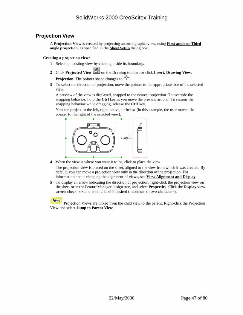
Projection View A Projection View is created by projecting an orthographic view, using First angle or Third angle projection, as specified in the Sheet Setup dialog box.
Creating a projection view: 1 Select an existing view by clicking inside its boundary.
2 Click Projected View on the Drawing toolbar, or click Insert, Drawing View,
Projection. The pointer shape changes to . 3 To select the direction of projection, move the pointer to the appropriate side of the selected
view. A preview of the view is displayed, snapped to the nearest projection. To override the
snapping behavior, hold the Ctrl key as you move the preview around. To resume the snapping behavior while dragging, release the Ctrl key.
You can project to the left, right, above, or below (in this example, the user moved the pointer to the right of the selected view).
4 When the view is where you want it to be, click to place the view. The projection view is placed on the sheet, aligned to the view from which it was created. By
default, you can move a projection view only in the direction of the projection. For information about changing the alignment of views, see View Alignment and Display.
5 To display an arrow indicating the direction of projection, right-click the projection view on the sheet or in the FeatureManager design tree, and select Properties. Click the Display view arrow check box and enter a label if desired (maximum of two characters).
Projection Views are linked from the child view to the parent. Right-click the Projection View and select Jump to Parent View.
SolidWorks 2000 CreoScitex Training
22/May/2000 Page 48 of 80
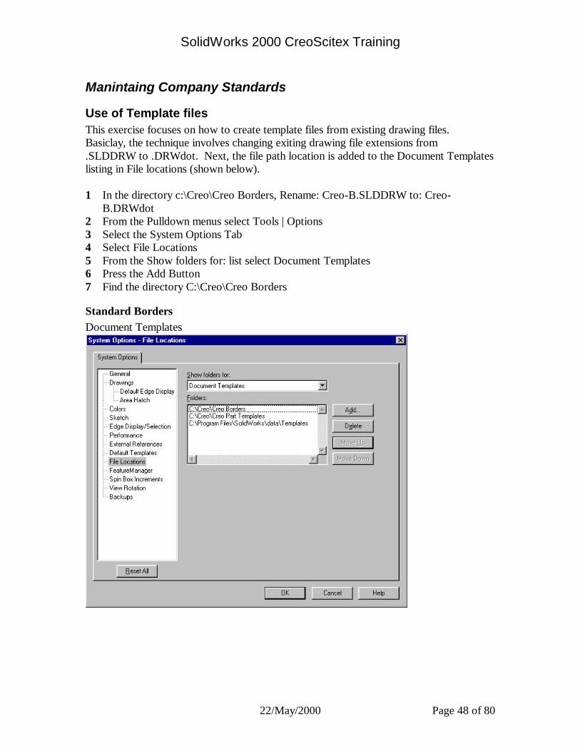
Manintaing Company Standards
Use of Template files This exercise focuses on how to create template files from existing drawing files. Basiclay, the technique involves changing exiting drawing file extensions from .SLDDRW to .DRWdot. Next, the file path location is added to the Document Templates listing in File locations (shown below). 1 In the directory c:\Creo\Creo Borders, Rename: Creo-B.SLDDRW to: Creo-
B.DRWdot 2 From the Pulldown menus select Tools | Options 3 Select the System Options Tab 4 Select File Locations 5 From the Show folders for: list select Document Templates 6 Press the Add Button 7 Find the directory C:\Creo\Creo Borders
Standard Borders Document Templates
SolidWorks 2000 CreoScitex Training
22/May/2000 Page 49 of 80
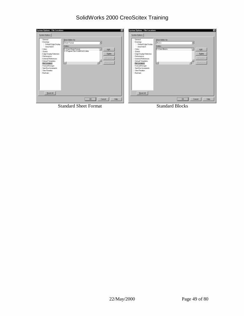
Standard Sheet Format Standard Blocks

SolidWorks 2000 CreoScitex Training
22/May/2000 Page 50 of 80
Linking Notes to Document Properties To automatically insert information in a drawing, you can link note text in the drawing sheet to document properties.
All SolidWorks documents have the system-defined property SW-File Name (the name of the document, without the extension). Additionally, drawings have the following system-defined properties:
Property Name Value SW-Current Sheet sheet number of the active sheet SW-Sheet Format Size sheet size of the active sheet format SW-Sheet Name name of the active sheet SW-Sheet Scale scale of the active sheet SW-Total Sheets total number of sheets in the active drawing
document
You can link a note to the properties of the model that is shown in the drawing (the SW-File Name property, or a user-defined custom property in the model document).
While you are editing the sheet format, a variable for the property name is displayed ($PRP: “property name”). When you return to editing the sheet, the value of the property is displayed, if it is found. If the property value cannot be found, the variable for the property name is displayed on the sheet.
A linked note can include additional text, and it can include links to more than one property. For example, to display the current sheet number and the total number of sheets, you can add this note:
SHEET $PRP: “SW-Current Sheet” OF $PRP: “SW-Total Sheets”
On the sheet, the property values are displayed: SHEET 1 OF 2 (on the first sheet of a two-sheet drawing)
To link a note in the sheet format to a property:
1 In the Properties dialog box for the Note, click Link to Property . 2 In the Link to Property dialog box, select a Property Name from the list. The list contains
the names of the system-defined properties, and any custom properties to which you have assigned values in the active drawing document.
3 To link the note to the properties of the model shown in the drawing, select the External model reference check box, then select a Property Name from the list. The value of the property for the model shown in the first view inserted into the sheet is displayed by default.
If the sheet contains views of more than one model, you can specify which view contains the model whose properties you want to use. Right-click the sheet, select Properties, then select the view from the list under Use custom property values from model shown in.
If no model is shown in the drawing (for example, when you are creating a new sheet format), you can either select a property from the drawing's list, or add a new custom property. The property is resolved when a model is added to the sheet.
When you save the sheet format, any new properties that you added are saved with the sheet format. The properties are added to any new drawing that uses the sheet format.
4 Update the drawing, if necessary.
SolidWorks 2000 CreoScitex Training
22/May/2000 Page 51 of 80
Cosmetic Threads You can represent threads on a part, assembly, or drawing, and you can attach a thread callout
note. You can add cosmetic threads to conical holes. If the conical thread does not end at a flat face, it is trimmed by the curved face.
A cosmetic thread differs from other annotations, in that it is an absorbed feature of the item to which it is attached. For example, the cosmetic thread on a hole is in the FeatureManager design tree under the Hole feature, along with the sketches used to create the hole.
Cosmetic threads added in a part or assembly can be imported to a drawing view. If you add a cosmetic thread while working in a drawing view, the part or assembly is updated to include a Cosmetic Thread feature.
For tap and pipe tap holes, you can add cosmetic threads in the Hole Wizard.
To insert cosmetic threads: 1 On a cylindrical feature (a boss, a cut, or a hole), click the circular edge where the thread
begins. If the hole is conical, select the major diameter.
2 Click Cosmetic Thread on the Annotations toolbar, or click Insert, Annotations, Cosmetic Thread.
3 In the Cosmetic Thread Properties dialog box, select the thread to apply. 4 Click OK.
To edit a cosmetic thread: 1 In a part or assembly document, right-click the Cosmetic Thread feature, and select Edit
Definition. You can select the feature either in the graphics area, or in the FeatureManager design tree. 2 Make the necessary changes in the Cosmetic Thread dialog box, and click OK.
To edit the thread callout on a cosmetic thread:
If you only need to edit the text of the thread callout note, double-click the note to edit in place. You can also right-click the note and select Properties.
To specify the line style and weight for cosmetic threads in the active drawing document: 1 Click Tools, Options. On the Document Properties tab, select Line Font. 2 In the Type of edge section, select Cosmetic Thread. 3 Choose a Style and Thickness from the lists.
The Preview box shows you the results

SolidWorks 2000 CreoScitex Training
22/May/2000 Page 52 of 80
Stacked Balloons
Stacked balloons have only one leader for a set. You can stack the balloons vertically or horizontally and up or down, or left or right.
You can insert a stacked balloon without selecting a component, so you can annotate an item that is part of an assembly but not actually modeled, such as glue or a liquid. A question mark appears in the balloon. Edit the question mark to replace it with your text.
If you change the Item Number in a stacked balloon, the item number in the bill of materials also changes.
You can also insert balloons that are not stacked.
To insert stacked balloons:
1 Click Stacked Balloon on the Annotation toolbar or click Insert, Annotations, Stacked Balloon.
2 Select the part where you want the balloon leader. 3 Continue to select parts. A balloon is added to the stack for each part selected. As you are adding the stacked balloons,
you can right-click any balloon in the stack, select Stack Direction, and choose a new stack direction (Up, Down, Left, Right).
Each balloon is a separate note that you can select to delete or edit.
To add balloons to the stack later: Right-click one of the stacked balloons and select Add to Stack.
To edit balloon text: Double-click the balloon text and edit in place.
To change the properties of the stacked balloons: 1 Right-click any balloon in the stack and select Properties. The Note Properties dialog box appears. 2 Change the following properties:
•In the Balloon note text section, select the type of text from the Upper or Lower lists, or both. (Lower is available only if you select the Circular Split Line style.)
•In the Stack Data section, select Up, Left, Down, or Right. Set the maximum stack length in Balloons per line.
•In the Leader section, choose Always show leaders or No leaders. Select or clear the Display with bent leader check box.
•Clear the Smart check box to choose an Arrow style from the list and choose Closest, Left, or Right for the Leader anchor.
•In the Balloon section, select the Style and Size from the lists. The Style of None is not available for stacked balloons.
3 Click OK.
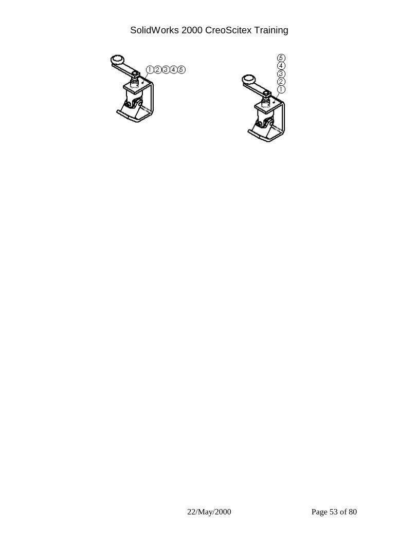
SolidWorks 2000 CreoScitex Training
22/May/2000 Page 53 of 80
SolidWorks 2000 CreoScitex Training
22/May/2000 Page 54 of 80
Bill of Materials Lets you insert a bill of materials into the drawing of an assembly. If you add or delete components in the assembly, the bill of materials automatically updates to reflect the changes if you select the Automatic update of BOM option under Tools, Options, System Options, Drawings. NOTE: To insert a bill of materials in a drawing, you must have Microsoft Excel 97 or later
installed on your computer.
To insert a bill of materials: 1 With a drawing view selected, click Insert, Bill of Materials. 2 In the Select a BOM Template dialog box, select the Excel template for the BOM. The default BOM template is in install_folder\lang\english\Bomtemp.xls. You can
customize the template by adding columns or changing the text formatting. You can also create new templates to meet your company’s standards.
3 Select from the following options:
•Use summary info title as part number. If you assigned a part identifier number in the title box of the Summary Info for the part, you can use that identifier in the bill of materials.
•Use the document’s note font when creating the table. When selected, the BOM uses the text font specified for notes, under Tools, Options, Document Properties, Detailing, Notes, Font. Otherwise, the font specified in the template is used.
4 Specify the way to list sub-assemblies and their components in the bill of materials:
•Show parts only. Select this option to list only parts in the bill of materials. Subassemblies are not listed; their components are listed as individual items.
•Show top level subassemblies and parts only. Select this option to list parts and subassemblies in the bill of materials. Each subassembly type is an item; the individual subassembly components are not listed.
•Show subassemblies and parts in an indented list. Subassemblies are listed as items; subassembly components are shown below the subassembly to which they belong, but without item numbers.
5 Under Anchor point, select from the following options:
•Use table anchor point. The standard templates supplied with the software include an anchor point for placing the BOM in a specific location on the sheet. To use the point, select this option, then select which corner of the BOM table to make coincident with the point (top right, bottom left, etc.). If you do not use the anchor point, the BOM is placed on the sheet near the selected view. See Anchor Point for Bill of Materials .
•Add new items by extending top border of table. New components are always added at the bottom of the table, and the rest of the table shifts upward. The last row of the table remains in the same position on the drawing sheet. This option applies only when you do not use an anchor point.
6 Click OK. A bill of materials is displayed that lists the components of the assembly. To move the bill of materials on the drawing sheet, drag it to where you want to place it.

SolidWorks 2000 CreoScitex Training
22/May/2000 Page 55 of 80
Bill of Materials - Custom Properties You can add more information such as Material, Vendor_Number, Cost, and so on to the open part or sub-assembly document by clicking File, Properties, and selecting the Custom tab or the Configurations specific tab. (See Summary Info - Custom for information about specifying properties.)
Then, you can add columns for these properties to the default bill of materials template (found in \install_directory\lang\english\Bomtemp.xls), or to a custom template that you create. When the bill of materials is inserted into an assembly drawing, it will be automatically populated with the values for the properties you defined on the property sheet.
To add custom columns to the bill of materials: 1 Open the BOM template file. To add the columns to the default BOM template, open
install_directory\lang\english\Bomtemp.xls. To create a new BOM template, it is a good idea to make a copy of the default template, then
open the copy. 2 Insert a new column where you want the information to appear. The new column must be to
the left of the column marked $$END. 3 Enter the column heading for the property you want to display in that column, and press
Enter. The name appears in the Formula Bar in the Excel toolbar. This column heading does not need to match the custom property name.
4 Click the cell to select it, then click Insert, Name, Define and type in the name of the property that you want to appear in this column. This cell name replaces the default alphanumeric cell name that appears in the Name Box in the Excel toolbar whenever you click a cell.
The cell name is listed in the Names in workbook list for the selected cell. This name must match the name of the property from the part or sub-assembly document, and must not contain any spaces.
5 Click Add, then click OK. When you add a bill of materials to a drawing, it will now include the added column. The
cells will be populated with the values of the custom properties of the document, or the values of the configuration specific properties for the item.
NOTE: Do not change the cell names in the Name Box for the default columns in the BOM template. You may change the text in the column heading, but not the cell name.

SolidWorks 2000 CreoScitex Training
22/May/2000 Page 56 of 80
Summary Info – Custom Summary Info – Configuration Specific
Allows you to specify custom properties for the part, assembly, or drawing document, or configuration specific properties for the active part or assembly configuration.
You can use the properties in several ways:
•In a bill of materials
•As advanced selection criteria for managing assembly configurations
•In drawing sheet formats and to link notes to document properties
To enter custom properties: 1 Enter a Name for the property, or choose one from the list. If you plan to use the property as
a custom column in a Bill of Materials, do not include any spaces in the Name. 2 Select the Type of value the custom property will use. 3 Enter a Value for the custom property that is compatible with the selection in the Type box. 4 Click Add. The Properties box displays the name, value and type of the custom properties.
To modify custom properties: 1 In the Name box, click the property in the Name box that you want to change. 2 Edit the Type or Value as needed. 3 Click Modify.
To delete custom properties: 1 Click the property in the Properties box that you want to delete. 2 Click Delete.
SolidWorks 2000 CreoScitex Training
22/May/2000 Page 57 of 80
Detailing Overview You can add much of the necessary detailing of your models in part and assembly documents. This includes dimensions, notes, symbols, and so on. Then you can insert the dimensions and annotations from the model into a drawing. Once in the drawing, you can add reference dimensions, other annotations, and a bill of materials if required. Annotations and reference dimensions added in a drawing do not affect the part or assembly document.
Insert Model Items Inserts dimensions, annotations, and reference geometry from the model into the current drawing.
You can insert items into a selected feature, an assembly component, a drawing view, or all views. When inserting into all views, dimensions and annotations appear in the most appropriate view. Features that appear in partial views, such as Detail or Section views, are dimensioned in those views first. Inserting annotations this way reduces the effort required to clean up the drawing.
To insert existing annotations or reference geometry into a drawing: 1 To annotate a single feature or assembly component, select the item. To annotate a single drawing view, select the view. To annotate all the views at once, do not select anything.
2 Click Model Items on the Annotation toolbar, or click Insert, Model Items. 3 From the Insert Model Items dialog box, select the types of items to insert:
•Annotations - Cosmetic Threads, Datums, Datum Targets, Dimensions, Geometric Tolerances, Notes, Surface Finish Symbols, Weld Symbols. If you select Dimensions, you have the option of also inserting Instance/Revolution Counts if those dimensions exist in the part or assembly.
•Reference Geometry - Axes, Curves, Planes, Surfaces, Piping Points, Origins. - or - 4 Click the All Types check box to insert all of the annotations and reference geometry.
5 Select a layer from the Layers list (available if your drawing has layers) for the items to be inserted only in the specified layer.
6 From the Import From box, select one of the following options:
•Entire Model. Displays all of the selected item types that exist in the model.
•Selected Component. If this drawing is of an assembly, displays the items that exist on the selected component only.
•Selected Feature. Displays the annotations existing on the selected feature only. 7 Change the selection of views if necessary. To insert dimensions into selected views, clear
the Import Items into All Views check box, then click the desired views in the graphics area or FeatureManager design tree. The selected views are listed in the Import into Views box. Click the views again to remove them from the list; right-click the drawing sheet, and select Clear selections to remove all the views from the list.
SolidWorks 2000 CreoScitex Training
22/May/2000 Page 58 of 80
NOTE: When Selected Feature or Selected Component is checked, annotations for the item are displayed only in the view where you selected the item. You cannot select a different view or all views.
8 To prevent the insertion of annotations that belong to hidden model items, clear the Include dimensions from hidden features check box. Annotations on features that are completely hidden by other geometry are not inserted. The insertion operation is slower, but the resulting views do not contain annotations that you may not want.
9 Click OK to insert the items; click Cancel to exit without making the changes. Attachment points of imported annotations can be dragged, but not re-attached to another edge, face, vertex, and so on. You can toggle the visibility of individual reference geometry items. Right-click the item, and select Hide or Show.
NOTE: Imported annotations display in the default Imported Annotation color; reference annotations (added in the drawing) are displayed in the default Reference Annotation color. These colors are specified in Tools, Options, System Options, on the Color page.
Moving and Copying Dimensions Once dimensions are displayed, you can move them within a view or to another view. When you drag a dimension from one place to another, the dimension reattaches to the model, as appropriate. You can only move or copy dimensions to a view where the orientation is appropriate for that dimension. • To move a dimension within the view, drag the dimension to the new position. • To move a dimension from one view to another view, hold the Shift key as you drag the dimension into another view. • To copy a dimension from one view to another view, hold the Ctrl key as you drag the dimension into another view. • To move or copy several dimensions at once, hold the Ctrl key as you select
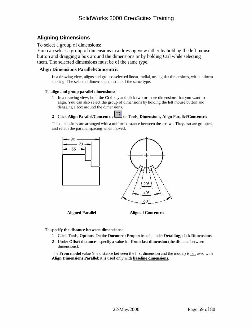
SolidWorks 2000 CreoScitex Training
22/May/2000 Page 59 of 80
Aligning Dimensions To select a group of dimensions: You can select a group of dimensions in a drawing view either by holding the left mouse button and dragging a box around the dimensions or by holding Ctrl while selecting them. The selected dimensions must be of the same type. Align Dimensions Parallel/Concentric
In a drawing view, aligns and groups selected linear, radial, or angular dimensions, with uniform spacing. The selected dimensions must be of the same type.
To align and group parallel dimensions: 1 In a drawing view, hold the Ctrl key and click two or more dimensions that you want to
align. You can also select the group of dimensions by holding the left mouse button and dragging a box around the dimensions.
2 Click Align Parallel/Concentric or Tools, Dimensions, Align Parallel/Concentric.
The dimensions are arranged with a uniform distance between the arrows. They also are grouped, and retain the parallel spacing when moved.
Aligned Parallel Aligned Concentric
To specify the distance between dimensions: 1 Click Tools, Options. On the Document Properties tab, under Detailing, click Dimensions. 2 Under Offset distances, specify a value for From last dimension (the distance between
dimensions).
The From model value (the distance between the first dimension and the model) is not used with Align Dimensions Parallel; it is used only with baseline dimensions.
SolidWorks 2000 CreoScitex Training
22/May/2000 Page 60 of 80
Center Marks You can place axis lines for showing center marks on circles or arcs that can be used as reference points for dimensioning. You can set options for the default size of center marks and choose whether or not to display extended axis lines. Click Tools, Options. On the Document Properties tab, select Detailing. In the Center marks section, type a size and select or clear Show lines. The options apply to the active document.
Center marks are available in drawings only.
Center marks in Auxiliary Views are oriented to the viewing direction such that one of the lines of the Center Mark is parallel to the view arrow direction.
To create center marks:.
1 Click Center Mark on the Annotations toolbar, or Insert, Annotations, Center Mark. 2 Click the model edges (circles or arcs) or silhouettes.
To change the display attributes of individual center marks, right-click the center mark and select Properties.
Hole Callouts Hole callouts are available in drawings. If you change a hole dimension in the model, the symbol updates automatically.
To add a hole callout symbol:
1 Click Hole Callout on the Annotations toolbar, or click Insert, Annotations, Hole Callout.
2 Click the edge of a hole. The Modify Text of Dimension dialog box appears, with symbols appropriate to the selected
hole. You can add text (for example, the number of places where the hole occurs). However, do
not change the dimensions or symbols for the size and type of hole in this dialog box. 3 Modify as necessary, and click OK.
When you right-click the hole callout and select Properties, the Dimension Properties dialog box appears. You can change properties of the hole callout in the dialog box. Click Modify Text to bring up the Modify Text of Dimension dialog box.

SolidWorks 2000 CreoScitex Training
22/May/2000 Page 61 of 80
RapidDraft Drawings
RapidDraft™ drawings are designed so you can open and work in drawing files without the model files being loaded into memory.
View borders in RapidDraft drawings are blue. When the referenced model is loaded into memory, the view borders change to gray or green.
If the referenced model is needed for an operation within a RapidDraft drawing, you are prompted to load the model file. You can load the model manually by right-clicking a view and selecting Load Model.
When a RapidDraft drawing is out of sync with its model, it prints with a water mark that states: SolidWorks RapidDraft – Out-of-Sync Print
Advantages of RapidDraft Drawings You can send RapidDraft drawings to other SolidWorks users without sending the model files. You also have more control over updating the drawing to the model. Members of the design team can work independently on the drawing, adding details and annotations, while other members edit the model. When the drawing and the model are synchronized, all the details and dimensions added to the drawing update to any geometric or topological changes in the model.
Performance
The time required to open a drawing in RapidDraft format is significantly reduced because the model files are not loaded. Because the model data is not stored in memory, more memory is available to process drawing data, which has significant performance implications for large assembly drawings. You have control over when to load the model, which takes time to load and update the drawing.
File Size
The RapidDraft format requires storing more edge data and less surface data. Therefore, some files are larger when converted to RapidDraft, while others are smaller. In general, if your drawings have section views, the file size should decrease. If the drawings do not have section views, the file size may increase. File size is directly related to the number of visible edges in the drawing. For example, if your parts have patterns of features with many instances, it is more likely that the file size will increase when converted to RapidDraft format.
Updating Views Some changes, such as changes to a section line, detail circle, scale, or projection angle, require a view update. When a drawing view requires an update, the view is displayed with a gray crosshatch pattern.
SolidWorks 2000 CreoScitex Training
22/May/2000 Page 62 of 80
SolidWorks Explorer -- Overview
The SolidWorks Explorer is a file management tool designed to help you perform such tasks as renaming, replacing, and copying SolidWorks files. You can show a document’s references, search for documents using a variety of criteria, and list all the places where a document is used. Renamed files are still available to those documents that reference them. NOTE: The SolidWorks Explorer is not a PDM (Product Data Management) tool; however, it
does perform many useful tasks and simplifies many file management processes.
You can use SolidWorks Explorer with or without the SolidWorks application.
To activate the SolidWorks Explorer:
•From within the SolidWorks application, click Tools, SolidWorks Explorer.
•From the Windows Start menu, click Programs, SolidWorks 2000, SolidWorks Explorer.
•Create a shortcut by dragging the SolidWorks Explorer icon to your desktop.
The SolidWorks Explorer window has several main features: •Path. At the top of the SolidWorks Explorer window is a box that displays the drive letter,
path, and name of the active document. Initially this is empty. • Click Browse to locate a document. - or - • Drag a document from the Windows Explorer to the Document window.
•Document window. This window lists the active document and its parent or child documents. Click on these document icons to select the documents that you want to manage. To change to another document, drag a different document from Windows Explorer or browse to a different document in the Path.
•Main window. This window displays the dialogs or graphics that are appropriate for the operation that you select.
•Operation window. This window displays the icons that represent the file management tasks that you can perform with SolidWorks Explorer.
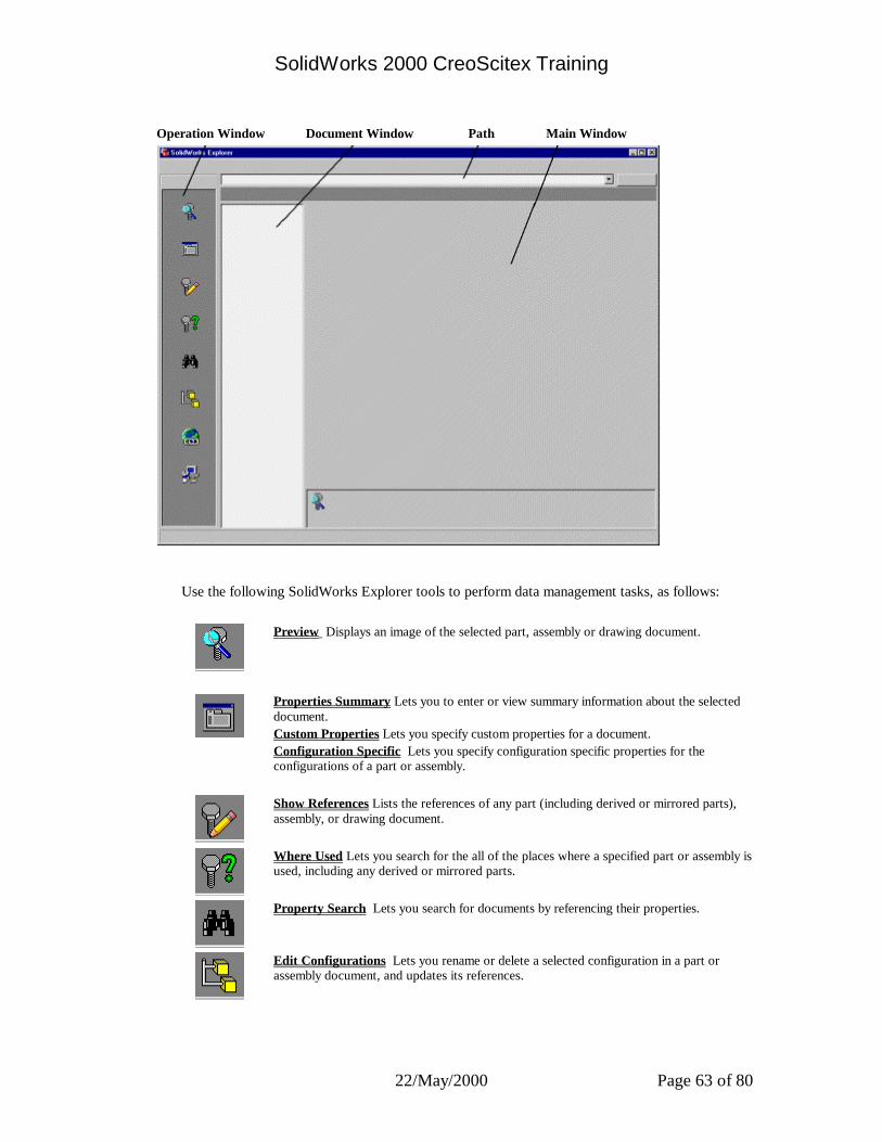
SolidWorks 2000 CreoScitex Training
22/May/2000 Page 63 of 80
Operation Window Document Window Path Main Window
Use the following SolidWorks Explorer tools to perform data management tasks, as follows:
Preview Displays an image of the selected part, assembly or drawing document.
Properties Summary Lets you to enter or view summary information about the selected document. Custom Properties Lets you specify custom properties for a document. Configuration Specific Lets you specify configuration specific properties for the configurations of a part or assembly.
Show References Lists the references of any part (including derived or mirrored parts), assembly, or drawing document.
Where Used Lets you search for the all of the places where a specified part or assembly is used, including any derived or mirrored parts.
Property Search Lets you search for documents by referencing their properties.
Edit Configurations Lets you rename or delete a selected configuration in a part or assembly document, and updates its references.

SolidWorks 2000 CreoScitex Training
22/May/2000 Page 64 of 80
Edit Hyperlinks Lets you list and edit any hyperlinks that the selected document may have.
Options Lets you change the default settings of SolidWorks Explorer.
SolidWorks Explorer lets you easily perform the following tasks on a selected document (or documents), and updates references to and from the document appropriately. Right-click in the Document window to access these functions. Copy Rename Replace
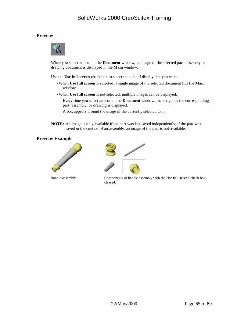
SolidWorks 2000 CreoScitex Training
22/May/2000 Page 65 of 80
Preview
When you select an icon in the Document window, an image of the selected part, assembly or drawing document is displayed in the Main window.
Use the Use full screen check box to select the kind of display that you want.
•When Use full screen is selected, a single image of the selected document fills the Main window.
•When Use full screen is not selected, multiple images can be displayed. Every time you select an icon in the Document window, the image for the corresponding part, assembly, or drawing is displayed. A box appears around the image of the currently selected icon.
NOTE: An image is only available if the part was last saved independently; if the part was saved in the context of an assembly, an image of the part is not available.
Preview Example
handle assembly Components of handle assembly with the Use full screen check box
cleared.

SolidWorks 2000 CreoScitex Training
22/May/2000 Page 66 of 80
Custom Properties
Allows you to specify custom properties for the part, assembly, or drawing document, or configuration specific properties for the active part or assembly configuration.
You can use the properties in several ways:
•Custom columns in a Bill of Materials
•Advanced criteria for selection or show/hide
•Linked to text in notes
To enter custom properties: 1 Enter a Name for the property, or choose one from the list. If you plan to use the property as
a custom column in a Bill of Materials, do not include any spaces in the Name. 2 Select the Type of value the property will use. 3 Enter a Value for the property that is compatible with the selection in the Type box. 4 Click Add. The Properties box displays the name, value and type of the property. 5 Click Reset to return to the previously saved properties. 6 Click Apply to save the changes.
To modify custom properties: 1 Select the name in the Properties box. 2 Edit the Type or Value as needed. 3 Click Modify.
To delete custom properties: 1 Click the property in the Properties box that you want to delete. 2 Click Remove.

SolidWorks 2000 CreoScitex Training
22/May/2000 Page 67 of 80
Properties Summary
Allows you to enter or view summary information about the part, assembly, or drawing document.
To enter or display summary information: 1 On the Summary tab, enter the appropriate information in the boxes provided for: Author,
Keywords, Comments, Title, and Subject. NOTE: If you insert a part identification number in the Title box, you can use that number
automatically when you create a bill of materials in an assembly drawing that contains that part. See Bill of Materials for more information.
The system provides read-only Statistics about the document’s creation date, the date last saved, and the name of the person who saved the document last.
2 Click Reset to return to the previously saved properties. 3 Click Apply to save the changes.
SolidWorks 2000 CreoScitex Training
22/May/2000 Page 68 of 80
Configuration Specific
Allows you to specify configuration specific properties for the active part or assembly configuration.
You can use the properties in several ways:
•Custom columns in a Bill of Materials
•Advanced criteria for selection or show/hide
•Linked to text in notes
To enter custom properties: 1 Select a configuration from the Configuration list. 2 Enter a Name for the property, or choose one from the list. If you plan to use the property as
a custom column in a Bill of Materials, do not include any spaces in the Name. 3 Select the Type of value the property will use. 4 Enter a Value for the property that is compatible with the selection in the Type box. 5 Click Add. The Properties box displays the name, value and type of the property. 6 Click Reset to return to the previously saved properties. 7 Click Apply to save the changes.
To modify custom properties: 1 Select the name in the Properties box. 2 Edit the Type or Value as needed. 3 Click Modify.
To delete custom properties: 1 Click the property in the Properties box that you want to delete. 2 Click Remove.

SolidWorks 2000 CreoScitex Training
22/May/2000 Page 69 of 80
Show References
You can list the references of any part (including derived parts), assembly, or drawing document.
To list the references for a part or a derived part, an assembly, an assembly component, or a drawing document: Click the document’s icon in the Document window.
The document is described by entries in the following columns:
•File name or New name. The name of the selected file appears in bold. Click the column heading to toggle between the display of the file name with the path or to display the file name without its path.
•Size. Displays the file size.
•Type. Displays the file type.
•Modified. Displays the time and date that the file was last modified.
•Attributes. Displays the attributes of the file, as reported by Windows Explorer.
To open the selected document, right-click in the Main window and select Open file in SolidWorks.
To export the list to an Excel spreadsheet, right-click in the Main window and select Export list to Excel. NOTE: The first column of the Excel spreadsheet uses either the short or long version of the file
name, depending on what is selected in the File name or New name column.
Show References Example In this example, assume there is an assembly A1 with two components P1 and P2. P2 has an in-context feature which references P1 in the assembly A1. When you show references for A1: • A1 appears in the Main window in bold font. • P1 and P2 appear because they are components of the assembly. When you show references for P1: P1 appears in the Main window in bold font. When you show references for P2: • P2 appears in the Main window in bold font • A1 and P1 appear because of the in-context feature.
SolidWorks 2000 CreoScitex Training
22/May/2000 Page 70 of 80
Options
Lets you change the default settings of SolidWorks Explorer.
Add or edit a search path. Add new search paths or edit the existing search paths used by the Where Used, Property Search, and Open functions. A search path is the default drive and directory structure to search when locating files.
•Search path: Modify, Delete, or Reset the name of the search path, or type a new name then click Add New to add a new search path.
•Directory list: Select a directory in the Directory list to edit. If one or more directories are displayed, you can Add New folders, Delete existing folders, and Move Up or Move Down to change the search order.
Display: Select the Show Description text at the bottom of every page check box to see the message at the bottom of each SolidWorks Explorer page. This text changes to describe the function of each Operation icon as you select it.
File open: Select the File Open should search ‘Document Folders’ for external references check box to display the file’s external references when you open a file from SolidWorks Explorer.
SolidWorks 2000 CreoScitex Training
22/May/2000 Page 71 of 80
Property Search
Lets you search for documents by referencing their property pages. The documents that meet the specified search criteria are listed.
To define selection criteria and begin the search: 1 Select a Search Path from the list, or click Browse and select a folder to search in. Select the
Search subfolders check box to include subfolders. 2 To use a set of previously specified criteria, click Load criteria and browse to the (.sqy) file. 3 Under Define additional criteria, select a Property from the list or type a user-defined
name in the Property box. 4 Select a Condition, type a Value, and click Add to list. The item appears in the Criteria box. 5 To add additional criteria for your search, click And or Or, then repeat steps 3 and 4. 6 To delete a criteria from the list, click the item in the Criteria box, and click Delete. To clear
the entire Criteria box, click New Search. 7 Click Find Now to begin the search. When one or more documents are found that meet the specified criteria, they are listed with
the following information:
•File name or New name. Click the column heading to toggle between the display of the file name with the path or to display the file name without its path.
•Type. Displays the file type.
•Size. Displays the file size.
•Date created. Displays the time and date that the file was created.
•Attributes. Displays the attributes of the file, as reported by Windows Explorer. 8 To open a selected document, right-click a document in the Main window and select Open
file in SolidWorks. 9 To export the list to an Excel spreadsheet, right-click and select Export list to Excel. NOTE: The first column of the Excel spreadsheet uses either the short or long version of the file
name, depending on what is selected in the File name or New name column.
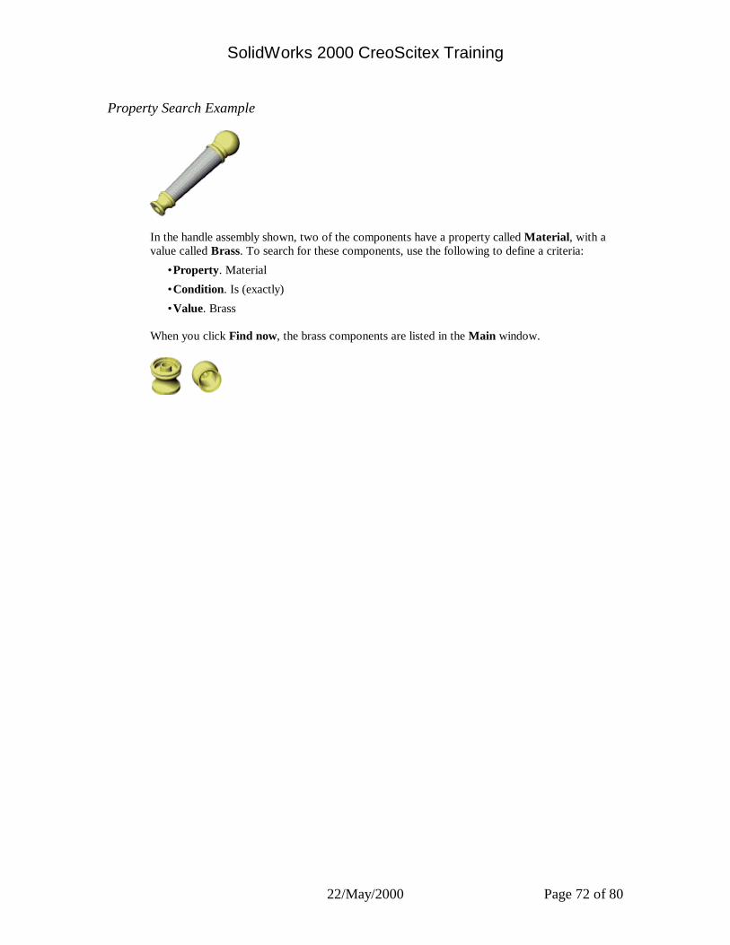
SolidWorks 2000 CreoScitex Training
22/May/2000 Page 72 of 80
Property Search Example
In the handle assembly shown, two of the components have a property called Material, with a value called Brass. To search for these components, use the following to define a criteria:
•Property. Material
•Condition. Is (exactly)
•Value. Brass
When you click Find now, the brass components are listed in the Main window.

SolidWorks 2000 CreoScitex Training
22/May/2000 Page 73 of 80
Edit Hyperlinks
Select an icon in the Document window to list and edit any hyperlinks that it may have.To open a hyperlink in the selected document, double-click the hyperlink text or icon.
Where Used
Lets you search for the all of the places where a specified part or assembly is used, including all the assembly or drawing documents, or any derived or mirrored parts.
To find where a document is used: 1 Select a Search Path from the list, or click Browse and select a folder to search in. The name
of the selected path appears in the Look in box. 2 In the Document window, click the icon of the document that you want to use as the subject
of your search. The name of the document appears in the File box. 3 Set the search criteria by selecting from the following check boxes:
• Look for assemblies and drawings • Look for derived/mirrored parts • Look for models defined in this assembly • Search subfolders
4 Click Find Now to begin the search. 5 Click New Search to clear the selections from a previous search and start again. The documents are described by entries in the following columns:
•Used by. Lists the other documents that use the subject of the search. To display the full path name and file name, click the column heading when it says click to show long name. To display the file name without its path, click the column heading when it says click to show short name.
•Used as. Describes the way the search subject is used as follows: model reference, modeling context, or derived/mirrored part.
•Found. Lists all the occurrences of the document that is the search subject. To display the full path name of its various locations, click the column heading when it says click to show long name.
To open a selected document, right-click a document in the Main window and select Open file in SolidWorks.
To export the list to an Excel spreadsheet, right-click and select Export list to Excel. NOTE: The columns of the Excel spreadsheet use either the short or long version of the file
name, depending on what is selected in the Used by or Found columns of the list in the Where Used dialog.
SolidWorks 2000 CreoScitex Training
22/May/2000 Page 74 of 80
Where Used Example In this example, assume there is an assembly A1 with two components P1 and P2. P1 and P2 each have their own detail drawing named D1 and D2 respectively. • When you search for where P1 is used, A1 and D1 appear in the Main window. • When you search for where P2 is used, A1 and D2 appear in the Main window.File
To open a file in the SolidWorks Explorer:
• Click File on the menu bar and browse to select a file to open. • Click Browse next to the Path to locate a document, then click Open. • Drag a document from Windows Explorer to the Document window.
Edit
To copy or rename a file from the SolidWorks Explorer:
•Click Edit on the menu bar. - or -
•Right-click the file name in the Document window and select Copy, Rename, or Replace, if appropriate.
The Copy Document, Rename Document, or Replace Document dialog box appears in the Main window. You are able to browse to find the filename that you want, if necessary.
Tools
When you click Tools on the menu bar, you can select any of the SolidWorks Explorer operations from the list:
Preview Property Search
Properties Edit Configurations
Show References Edit Hyperlinks
Where Used Options

SolidWorks 2000 CreoScitex Training
22/May/2000 Page 75 of 80
Copy
Copies a selected document (or a document and its children) and updates references.
To copy a document: 1 Right-click a document in the Document window and select Copy. The document’s name appears in the Copy box. The new document name and suggested path appear in the To box. The new name is the
same as the original name with the addition of “Rev” and a revision number. For example: “Part1.SLDPRT” becomes “Part1Rev2.SLDPRT”
NOTE: It is important to remember that SolidWorks Explorer does not provide true revision control, in the same manner as a PDM (Product Data Management) tool.
2 To copy the document to a new location, click Browse and select a new folder. 3 If the document has child documents that are dependent on it, you can select the Copy
children check box to copy them all at the same time and to the same location. If you select Copy children, the document’s dependencies are listed. You have several
options:
•Instead of Rev(n), you can enter other revision identifying characters to add to the original document name.
•You can select Prefix or Suffix to change the location of the revision identifier in relation to the original document name. For example: “Rev2Part1.SLDPRT” or “Part1Rev2.SLDPRT”
•You can make copies of all the documents in the list or you can clear the check marks of some documents so copies of them will not be made. Click Deselect all to clear all of the check marks.
4 You can search for other places where this document is used by selecting the Find where used check box, clicking Search rules to select search criteria to use, then clicking Find now. Click Reset if you want to perform a new search.
•Look for assemblies and drawings
•Look for derived/mirrored parts
•Look for models defined in this assembly
•Search subfolders 5 In the Find where used list you can do the following:
•To open a selected document, right-click a document and select Open File in SolidWorks.
•To export the list to an Excel spreadsheet, right-click and select Export list to Excel. NOTE: The first column of the Excel spreadsheet uses either the short or long version of the file
name, depending on what is selected in the Used by and New name columns in the Find where used list.
6 Click Apply to make the copies of the selected documents. The names of the documents that were copied successfully are displayed in blue font. The
names of the documents that were not copied successfully are displayed in red font.
SolidWorks 2000 CreoScitex Training
22/May/2000 Page 76 of 80
Rename
Renames one or more selected documents and updates all the references.
To rename a document: 1 Right-click a document in the Document window and select Rename.
The document’s name appears in the Rename box and in the To box. 2 Select the name in the To box and enter a new name. 3 To search for other places where this document is used select the Find where used check
box. Click Search rules to select search criteria to use, and then click Find Now. Click Reset if you want to perform a new search.
•Look for assemblies and drawings
•Look for derived/mirrored parts
•Look for models defined in this assembly
•Search subfolders 4 In the resulting list you can do the following:
•If you leave the Update check box checked, all the documents in the list are automatically updated to reference the renamed document by its new name. If you clear the Update check box, you must manually update each of the referencing documents yourself.
•To open a selected document, right-click a document and select Open file in SolidWorks.
•To export the list to an Excel spreadsheet, right-click and select Export list to Excel. NOTE: The first column of the Excel spreadsheet uses either the short or long version of the file
name, depending on what is selected in the Used by list. 5 Click Apply to change the name of the selected documents. The names of the documents that were changed and updated successfully are displayed in
blue font. The names of the documents that were not changed successfully are displayed in red font.
SolidWorks 2000 CreoScitex Training
22/May/2000 Page 77 of 80
Replace
Replaces a selected part or assembly document and updates its references.
To replace a document: 1 Right-click a part or assembly Document in the document window and select Replace. The document’s name appears in the Replace box and in the With box. 2 Select the name in the With box and click Browse to find a document to use as a
replacement. 3 To search for other places where this document is used select the Find where used check
box. Click Search rules to select search criteria to use, and then click Find now. Click Reset if you want to perform a new search.
•Look for assemblies and drawings
•Look for derived/mirrored parts
•Look for models defined in this assembly
•Search subfolders 4 In the resulting list you can do the following:
•If you leave the Update check box checked, all the documents in the list are automatically updated to reference the replacement document by its name. If you clear the Update check box, you must manually update each of the referencing documents yourself.
•To open a selected document, right-click a document and select Open file in SolidWorks.
•To export the list to an Excel spreadsheet, right-click and select Export list to Excel. NOTE: The first column of the Excel spreadsheet uses either the short or long version of the file
name, depending on what is selected in the Used by column in the Replace Document list.
5 Click Apply to replace the selected documents. The names of the documents that were replaced and updated successfully are displayed in
blue font. The names of the documents that were not replaced successfully are displayed in red font.

SolidWorks 2000 CreoScitex Training
22/May/2000 Page 78 of 80
Edit Configurations
Renames or deletes a selected configuration in part or assembly document, and updates its references. The part or assembly document must not be open in either SolidWorks or the SolidWorks Explorer.
To rename a configuration: 1 Select a document's icon in the Document window to list the configurations of the selected
document. 2 Select the configuration to rename. 3 Click-pause-click the configuration name and enter a new name. The current configuration name and the new name are displayed. 4 Click Apply. If the document is not open, the name change takes place. If the document is in use, the name cannot change. Click Reset and make the name change at
another time.
To delete a configuration: 1 Select a document's icon in the Document window to list the configurations of the selected
document. 2 Select the configuration to delete and press the Delete key. 3 Click Apply. If the document is not open, the deletion takes place. If the document is in use, you cannot delete the configuration. Click Reset and delete the
configuration at another time.
Look for assemblies and drawings
Searches for all assemblies and drawings where the selected file is used.
Look for derived/mirrored parts
Searches for all dervied parts (base, mirror, or derived component) where the selected file is used.
Look for models defined in this assembly
Searches for all components created in the context of the selected assembly.
Search subfolders
Searches subfolders for documents where the selected document is used.

SolidWorks 2000 CreoScitex Training
22/May/2000 Page 79 of 80
Importing/Exporting SolidWorks Documents You can import files to the SolidWorks software from other applications. You can export SolidWorks documents to a number of formats for use with other applications. The following table displays the data translation methods available for SolidWorks documents:
Import Export Import Export Import ExportIGES X X X X
Parasolid X X X XSTEP X X X XACIS X X X X
VDAFS X XSTL X X
DXF/DWG X XVRML X X X XTIFF X X X X X
Unigraphics XPro/ENGINEER X
Parts Assemblies Drawings
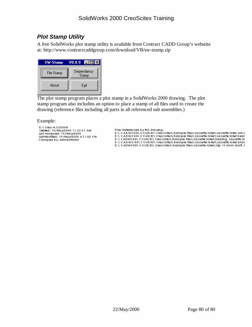
SolidWorks 2000 CreoScitex Training
22/May/2000 Page 80 of 80
Plot Stamp Utility A free SolidWorks plot stamp utility is available from Contract CADD Group’s webstite at: http://www.contractcaddgroup.com/download/VB/sw-stamp.zip
The plot stamp program places a plot stamp in a SolidWorks 2000 drawing. The plot stamp program also includins an option to place a stamp of all files used to create the drawing (reference files including all parts in all referenced sub assemblies.) Example:
Related Documents