Copyright Warning & Restrictions The copyright law of the United States (Title 17, United States Code) governs the making of photocopies or other reproductions of copyrighted material. Under certain conditions specified in the law, libraries and archives are authorized to furnish a photocopy or other reproduction. One of these specified conditions is that the photocopy or reproduction is not to be “used for any purpose other than private study, scholarship, or research.” If a, user makes a request for, or later uses, a photocopy or reproduction for purposes in excess of “fair use” that user may be liable for copyright infringement, This institution reserves the right to refuse to accept a copying order if, in its judgment, fulfillment of the order would involve violation of copyright law. Please Note: The author retains the copyright while the New Jersey Institute of Technology reserves the right to distribute this thesis or dissertation Printing note: If you do not wish to print this page, then select “Pages from: first page # to: last page #” on the print dialog screen

Welcome message from author
This document is posted to help you gain knowledge. Please leave a comment to let me know what you think about it! Share it to your friends and learn new things together.
Transcript

Copyright Warning & Restrictions
The copyright law of the United States (Title 17, United States Code) governs the making of photocopies or other
reproductions of copyrighted material.
Under certain conditions specified in the law, libraries and archives are authorized to furnish a photocopy or other
reproduction. One of these specified conditions is that the photocopy or reproduction is not to be “used for any
purpose other than private study, scholarship, or research.” If a, user makes a request for, or later uses, a photocopy or reproduction for purposes in excess of “fair use” that user
may be liable for copyright infringement,
This institution reserves the right to refuse to accept a copying order if, in its judgment, fulfillment of the order
would involve violation of copyright law.
Please Note: The author retains the copyright while the New Jersey Institute of Technology reserves the right to
distribute this thesis or dissertation
Printing note: If you do not wish to print this page, then select “Pages from: first page # to: last page #” on the print dialog screen

The Van Houten library has removed some of the personal information and all signatures from the approval page and biographical sketches of theses and dissertations in order to protect the identity of NJIT graduates and faculty.
ABSTRACT
SOLIDS SUSPENSION AND POWER DISSIPATION IN STIRRED TANKSAGITATED BY AN IMPELLER NEAR THE TANK BOTTOM
byErnesto Uehara Nagamine
In this work, the effect of very small impeller clearances off the tank bottom, C, on
complete solid off-bottom suspension, Njs, was investigated. Four types of impellers were
used: six-blade flat-disk turbine, six-blade flat-blade turbine, six-blade flat (45°) pitched-
blade turbine, and the high efficiency impeller Chemineer HE-3. The effects of the impeller
diameter, D, tank diameter, T, and solids loading, X, were quantified. The presence of two
impellers was analyzed using impellers of the same type and size.
Typically, Njs and the power consumption were found to decrease with the
impeller clearance. However, for lower C/T values, a slight increase was observed for
axial impellers, especially for low D/T ratios (less than 0.261). The power consumption
was lower for the axial-flow impellers as compared with the radial-flow impellers. For disk
and flat-blade turbines, a change in the flow pattern was observed in the range of 0.13 <
C/T < 0.19 and 0.19 < C/T < 0.24, respectively. No change in flow pattern was observed
up to C/T = 0.25, for the flat (45°) pitched-blade turbines and the Chemineer impellers.
Correlations to predict the value of Njs as a function of impeller clearance were obtained,
for each type of impeller.
SOLIDS SUSPENSION AND POWER DISSIPATION IN STIRRED TANKSAGITATED BY AN IMPELLER NEAR THE TANK BOTTOM
byErnesto Uehara Nagamine
A ThesisSubmitted to the Faculty of
New Jersey Institute of Technologyin Partial Fulfillment of the Requirements for the Degree of
Master of Science in Chemical Engineering
Department of Chemical Engineering,Chemistry, and Environmental Science
October 1996


APPROVAL PAGE
SOLIDS SUSPENSION AND POWER DISSIPATION IN STIRRED TANKSAGITATED BY AN IMPELLER NEAR THE TANK BOTTOM
Ernesto Uehara Nagamine
Dr. Piero Armenante, Thesis Adviser DateProfessor of Chemical Engineering, Chemistry, and Environmental Science,NJIT
/ 1/
Dr. Gordon Lewandowski, Committee Member DateDepartment Chairman and Professor of Chemical Engineering, Chemistry, andEnvironmental Science, NJIT
Dr. Dana Knox, Committee Member DateProfessor of Chemical Engineering, Chemistry, and Environmental Science,NJIT

BIOGRAPHICAL SKETCH
Author: Ernesto Uehara Nagamine
Degree: Master of Science
Date: October 1996
Undergraduate and Graduate Education:
• Master of Science in Chemical Engineering,New Jersey Institute of Technology, Newark, NJ, 1996
• Bachelor of Science in Chemical Engineering,Engineering National University, Lima, Peru, 1984
Major: Chemical Engineering

This thesis is dedicated to my wife

ACKNOWLEDGMENT
I would like to express my sincere gratitude to my thesis advisor, Dr. Piero M.
Armenante, for his guidance and support. His efforts were truly appreciated.
I would like to acknowledge to the members of my thesis committee, Dr. Gordon
Lewandowski and Dr. Dana Knox, for their constructive criticism.
I appreciate the mixing laboratory members, Dr. Chun-Chiao Chou and Mr.
Changgen Luo, for their suggestions and assistance.
vi
TABLE OF CONTENTS
Chapter Page
1 INTRODUCTION 1
2 LITERATURE SURVEY 3
2.1 Effect of Impeller Clearance 3
2.1.1 Minimum Agitation Speed (Njs) and Power Dissipation (Pjs) 3
2.1.2 Power Number (Npo) 6
2.1.3 Change of Flow Pattern 8
2.2 Effects of Impeller Diameter, Tank Diameter, and Solids Loading 10
2.3 Effects of Other Variables 12
2.4 Mechanisms of Suspension 14
2.5 Effect of Multiple Impellers 15
3 CORRELATIONS AND THEORIES AVAILABLE 16
3.1 Zwietering (1958) Correlation 16
3.2 Baldi et al. (1978) Theoretical Model 18
3.3 Conti et al. (1981) Correlation 22
4 EXPERIMENTAL EQUIPMENT AND PROCEDURE 23
4.1 Experimental Set-Up 23
4.2 Experimental Procedure 31
5 RESULTS AND DISCUSSION 36
5.1 Effect of Impeller Clearance 36
vii
TABLE OF CONTENTS(Continued)
Chapter Page
5.1.1 Minimum Agitation Speed (Njs) 37
5.1.2 Power Dissipation at Minimun Agitation Speed (Pjs) 40
5.1.3 Power Number (Npo) 44
5.1.4 Change of Flow Pattern 49
5.1.5 Comparison of Njs and Pjs at Constant D/T 51
5.2 Effect of Impeller Diameter 53
5.3 Effect of Tank Diameter 56
5.4 Effect of Solids Loading 58
5.5 Comparison at C/T = 0 59
5.6 Scale-Up 61
5.7 Dual-Impeller Systems 63
6 EXTENSION OF CORRELATIONSAND APPLICATION OF THEORETICAL MODEL 65
6.1 Extension of Zwietering (1958) Correlation 65
6.2 Application of Baldi et al. (1978) Theoretical Model 69
6.3 Extension of Baldi et al. (1978) Theoretical Model 74
7 CONCLUSIONS 80
APPENDIX A: FIGURES FOR CHAPTER 5 AND 6 82
APPENDIX B: EXPERIMENTAL DATA 115
REFERENCES 142
viii

LIST OF TABLES
Table Page
1 Dimensions of Vessels 23
2 Impeller Types and Dimensions 26
3 Experimental Determination of the Power Number (Npo) Using Water Only 33
4 Experimental Sets 3 5
5 Optimum Clearances for Minimum Agitation Speed (Ns) 3 7
6 Correlations for Minimum Agitation Speed (Njs) 39
7 Optimum Clearances for Power Dissipation (Pjs) 41
8 Correlations for Power Dissipation (Pjs) 43
9 Comparison between Experimental Values for Power Number (Npo) 46
10 Correlations for Power Number (Npo) 48
1 1 Change of Flow Pattern Observed in this Work 50
12 Comparison of Exponents Found for Impeller Diameter (D) 54
13 Exponents of Njs Found in this WorkConstant C/T 58
14 Comparison at C/T = 0 60
15 Exponents of Njs and Pjs Found in this Work
Constant C'/T 62
16 Comparison of Njs Values with Zwietering CorrelationSix-Blade Flat-Disk Turbine (6FDT) 65
17 Extension of Zwietering Correlation 68
ix
LIST OF TABLES(Continued)
Table Page
18 Application of Baldi et al. Model to Various Impeller Configurations
Constant C'/D 73
19 Application of Baldi et al. Model to Various Impeller ConfigurationsConstant C'/T 73
20 Comparison of Njs Values with Conti et al. Correlation
Six-Blade Flat-Disk Turbine (6FDT) . 74
21 Extension of Baldi et al. Model 77
22 Expressions for Njs deduced from Z* Correlations
6FDT, 6FBT, and 6FPT 78
23 Expressions for Njs deduced from Z* Correlations
CHEM 79
24 Effect of C/T on Njs, Pjs, and Npo. 6FDT. T = 0.292 m 116
25 Effect of C'/D and C'/T on Njs, Pjs, and Npo. 6FDT. T = 0.292 m 117
26 Effect of C/T on Njs, Pjs, and Npo. 6FDT. T = 0.292 m
Transition Region 118
27 Effect of C/T on Njs, Pjs, and Npo. 6FBT. T = 0.292 m 119
28 Effect of C'/D and CUT on Njs, Pjs, and Npo. 6FBT. T = 0.292 m 120
29 Effect of C/T on Njs, Pjs, and Npo. 6FBT. T = 0.292 mTransition Region 121
30 Effect of C/T on Njs, Pjs, and Npo. 6FPT. T = 0.292 m 122
31 Effect of C'/D and C'/T on Njs, Pjs, and Npo. 6FPT. T = 0.292 m 123
32 Effect of C/T on Njs, Pjs, and Npo. CHEM. T = 0.292 m 124
LIST OF TABLES(Continued)
Table Page
33 Effect of C/T on Njs, Pjs, and Npo. CHEM. T = 0.584 m 125
34 Effect of C'/D on Njs, Pjs, and Npo. CHEM. T = 0.584 m 126
35 Effect of T on Njs, Pjs, and Npo at Constant D/T (= 0.348). 6FDTConstant C/T (C'/T) 127
36 Effect of T on Njs, Pjs, and Npo at Constant D 0.0762 m). 6FDTConstant C/T 128
37 Effect of T on Njs, Pjs, and Npo at Constant D (= 0.0635 m). 6FDTConstant C/T 129
38 Effect of T on Njs, Pjs, and Npo at Constant D/T (= 0.348). 6FBTConstant C/T (C'/T) 130
39 Effect of T on Njs, Pjs, and Npo at Constant D (= 0.0762 m). 6FBTConstant C/T 131
40 Effect of T on Njs, Pjs, and Npo at Constant D (= 0.0635 m). 6FBTConstant C/T 132
41 Effect of T on Njs, Pjs, and Npo at Constant D/T (= 0.348). 6FPTConstant C/T (C'/T) 133
42 Effect of T on Njs, Pjs, and Npo at Constant D (= 0.0762 m). 6FPTConstant C/T 134
43 Effect of X on Njs, Pjs, and Npo. 6FDT. D/T = 0.348Constant C/T (C'/T) 135
44 Effect of X on Njs, Pjs, and Npo. 6FBT. D/T = 0.348Constant C/T (C'/T) 136
45 Effect of X on Njs, Pjs, and Npo. 6FPT. D/T = 0.348Constant C/T (C'/T) 137
xi

LIST OF TABLES(Continued)
Table Page
46 Effect of X on Njs, Pjs, and Npo. CHEM. D/T = 0.348Constant C/T (C7T) 138
47 Dual-6FDT System. Effect of C/T on Njs, Pjs, and NpoT = 0.292 m, D/T 0.261, S/D 1 139
48 Dual-6FBT System. Effect of C/T on Njs, Pjs, and NpoT = 0.292 m, D/T = 0.261, S/D = 1 140
49 Dual-6FPT System. Effect of C/T on Njs, Pjs, and NpoT = 0.292 m, D/T = 0.261, S/D = 1 141
xii
LIST OF FIGURES
Figure Page
1 Experimental Set-Up 24
2 Impeller Geometry 27
3 Sketch of Agitated Vessels 29
4 Calibration Curves for Strain Gages 29
5 Effect of C/T on Njs (6FDT, 6FBT, 6FPT, CHEM) 83
6 Effect of C/T on Pjs (6FDT, 6FBT, 6FPT, CHEM) 85
7 Effect of C/T on Npo (6FDT, 6FBT, 6FPT, CHEM) 87
8 Power Number Correlation (6FDT, 6FBT, 6FPT, CHEM) 89
9 Comparison at D/T = 0.348 (Njs, Pjs, Npo) 91
10 Comparison at D/T = 0.261 (Njs, Pjs, Npo) 92
11 Comparison at D/T = 0.217 (Njs, Pjs, Npo) 93
12 Effect of D on Njs (C/T) (6FDT, 6FBT, 6FPT, CHEM) 94
13 Effect of D on Njs (C'/T) (6FDT, 6FBT, 6FPT) 96
14 Effect of D on Njs (C'/D) (6FDT, 6FBT, 6FPT, CHEM) 97
15 Effect of T on Njs (D/T) (6FDT, 6FBT, 6FPT) 98
16 Effect of T on Njs (D) (6FDT, 6FBT, 6FPT) 99
17 Effect of X on Njs (C/T) (6FDT, 6FBT, 6FPT, CHEM) 100
18 Effect of D on Pjs (C'/T) (6FDT, 6FBT) 102
19 Effect of T on Pjs (D/T) (6FDT, 6FBT, 6FPT) 103
LIST OF FIGURES(Continued)
Figure Page
20 Effect of X on Pjs (C'/T) (6FDT, 6FBT, 6FPT, CHEM) 104
21 Dual-6FDT System (Effect of C/T on Njs, Pjs, and Npo) 106
22 Dual-6FBT System (Effect of C/T on Njs, Pjs, and Npo) 107
23 Dual-6FPT System (Effect of C/T on Nj s, Pj s, and Npo) 108
24 Extension of Zwietering Correlation
(6FDT, 6FBT, 6FPT, CHEM) 109
25 Effect of Rem on Z Values for Various C'/D Ratios(6FDT, 6FBT, 6FPT, CHEM) 111
26 Effect of Rem on Z Values for Various C'/T Ratios(6FDT, 6FBT, 6FPT) 112
27 Extension of Baldi et al Model(6FDT, 6FBT, 6FPT, CHEM) 113
xiv

NOMENCLATURE
A Impeller blade angle (degree)
A' Impeller blade angle (radian)
Ap Impeller pitch (m)
C Impeller off-bottom clearance, distance from the lowest point of the impeller tothe tank bottom (m)
C' Impeller off-bottom clearance, distance from the impeller centerline to the tankbottom (m)
CBS Complete off-bottom suspension, as defined by Zwietering (1958)
D Impeller diameter (m)
dp Particle size (m)
et Local energy dissipation rate (watts/kg)
Local energy dissipation rate at the bottom (watts/kg)
H Liquid height (m)
k Blade thickness (m)
K Calibration constant for strain gages (kg f-m/mV-s)
L Blade length (m)
N Impeller speed (rpm)
n Number of impellers
nB Number of baffles
nb Number of blades
Njs Minimum agitation speed (rpm)
xv

NOMENCLATURE(Continued)
Njs' Minimum agitation speed (rps)
P Power drawn by impeller (watts)
Pjs Power dissipation at minimum agitation speed (watts)
S Spacing between impellers (m)
T Vessel diameter (m)
us Relative vertical velocity between particle and fluid in turbulent region (m/s)
vl Liquid fraction based on vessel volume (dimensionless)
Vt Volume of vessel (m3)
WB Baffle width (m)
Wb Blade width (m)
X Weight percentage of solids, 100g/g (wt/wt%)
Dimensionless number
Ar Archimedes number, dp3 gAp/vp (dimensionless)
Fr Froude number, N2D/g (dimensionless)
Npo Power number, P/pN' 3 11)4 5 (dimensionless)
Re Reynolds number, Njs'13 3 p 1/t (dimensionless)
Rem Modified Reynolds number, Njs'D3p i/liT (dimensionless)
S' Zwietering correlation parameter (dimensionless)
Z Baldi et aL theoretical model parameter, dp"(gAp/p 1 ) 1/2/1\ip01/30'-'513Njs'(dimensionless)
xvi

NOMENCLATURE(Continued)
Impeller Type
CHEM Chemineer HE-3
6FBT Six-blade flat-blade turbine
6FDT Six-blade flat-disk turbine
6FPT Six-blade flat (45°) pitched-blade turbine
Symbols
1-1 Dynamic viscosity (kg,/m-s)
v Kinematic viscosity (m2/s)
pl Density of liquid (kg/m3)
Ps Density of solid (kg/m 3)
Ap Solid-liquid density difference, p s -pi (kg/ m3 )
Subscripts
Liquid phase
s Solid phase
Constants
g Gravitational constant (9.81 m/s2)
ge Conversion factor (9.81 kg-m/kgrs2)
xvii
CHAPTER 1
INTRODUCTION
Solid-liquid mixing is one of the most common operations in the chemical process
industry. Mechanically agitated vessels are frequently used to bring about adequate solid-
liquid contact.
Depending on the application — such a promoting a chemical reaction or mass
transfer between the phases, or obtaining a uniform particle concentration in an effluent
stream — the suspension can be classified as either complete off-bottom suspension
(CBS) or relatively uniform suspension. The former is the most important state for the
design of solid-liquid agitation apparatus in which no particle rests on the tank base for
longer than one or two seconds. This level of agitation often represents an optimum value
for operating conditions relative to the capital investment and operating costs to achieve
desired rates of mass transfer and chemical reaction. Until such a condition is reached, the
total solid-liquid interfacial area is not completely or efficiently utilized and above this
speed, the rate of mass transfer typically increases very slowly. Therefore, any additional
energy beyond that required for this minimum agitation or just-suspended speed (Njs),
also called critical impeller speed, is not typically useful. Consequently, the knowledge of
Njs is very important.
A study of solids suspension in liquid by mechanical agitation includes several
basic considerations: vessel dimensions and geometry, impeller type, dimensions and
geometry, solids and liquid properties, and solids loading.
1

2
The impeller clearance (often expressed in relative terms as the impeller off-bottom
clearance to tank diameter ratio, C'/T) significantly influences the minimum agitation or
just-suspended speed. Two hydrodynamic regimes can typically be observed depending on
the impeller clearance. At high values of this variable, large vortices above and below the
impeller are present. At low values, the lower vortices are absent. In the latter case, the
minimum agitation is lower. Also, the decrease of the power consumption in this region
can be noticeable, since a considerable amount of power dissipated is caused by the
vortices below the impeller. The value of the impeller clearance, at which this
hydrodynamic change occurs, depends on the impeller type and size.
Because of its practical importance for industrial applications, in this research the
effect of very small impeller clearances off the tank bottom, on the minimum agitation
speed and power dissipation, for complete off-bottom suspension, was investigated using
different types of impellers. The specific objectives of this work are:
- Quantify the effect of small off-bottom clearances on the minimum agitation speed and
power dissipation at this state;
- Quantify the effect of the impeller diameter, tank diameter, and solids loading at low
off-bottom impeller clearances, and examine the effects of scale-up;
- Analyze the effect of the presence of two impellers with the lower impeller being
located very near to the tank bottom;
- Extend some of the empirical correlations for solids suspension, available in the
literature, to the region very near to the tank bottom, for different types of impellers;
- Produce a mathematical model to correlate the experimental results obtained.
CHAPTER 2
LITERATURE SURVEY
2.1 Effect of Impeller Clearance
Although, solids suspension have been studied extensively, the effect of positioning the
impeller very near to the tank bottom has received little attention. The most relevant
information about this effect will be presented in this section.
2.1.1 Minimum agitation Speed (Njs) and Power Dissipation (Pjs)
Zwietering (1958) found that for propeller, paddle, and vaned disk turbine the minimum
agitation speed (Njs), became smaller as the impeller off-bottom clearance to tank
diameter ratio (C'/T), was reduced. For six-blade flat-disk turbines, Njs was found to be
independent of C'/T in the range of 1/7 < C'/T < 1/2.
Zwietering also found from a graphical analysis of his experimental data, that the
influence of the impeller off-bottom clearance (C') could not be expressed in a power law
form. He considered to be more appropriate to use the ratio C'/T as a constant parameter
in his correlation. Chudacek (1986) also expressed doubts on the suitability of the power
law form to quantify the clearance effect in the overall range examined.
Kolar (1961) found the six-blade flat-disk turbines to be unsuitable for solids
suspension when such an impeller was positioned one-half of the tank diameter above the
bottom. Nienow (1968), contrary to Zwietering and Kolar, found that Njs for this impeller
decreases with the impeller clearance.
3
Conti et al. (1981) and Chapman et al. (1983) also found that the impeller
clearance has a significant effect on Njs for disk turbines.
Chudacek (1985) reported that for maximum suspension efficiency, the impeller
should be positioned with minimum clearance, as governed either by the settled solids
height or by the given tank geometry in all the cases, except for a profiled bottom tank at
high concentration (24.4 viv%) of finer and coarser slurries. In the last case, the optimum
clearance was one-third of the tank diameter. However, at this high solids concentration
the impeller was essentially embedded in the slurry.
Chudacek (1986) found that 98% complete suspension and complete off-bottom
suspension (CBS) are more sensitive to the impeller position than homogeneous
suspensions. In most geometries, a reduction in clearance typically lead to a reduction in
the impeller speed for complete suspension. Some exceptions were found for cone-and-
fillet tank due to bypass of liquid into the suction side of the impeller.
Raghava Rao et al. (1988b) found that the value of the critical impeller speed
decreases with a decrease in the impeller clearance for all the impellers. However, the
extent of reduction is greater for disk turbines and pitched-blade upflow impellers than for
pitched-blade dowflown impellers.
Oldshue and Sharma (1992) defined three distinct regions where C'/T has an effect
on Njs. Their data suggest that there is a relation between C'/T and D/T in the
determination of these regions. Myers et al. (1994a) reported that the effect of C'/T is
much less than that of D/T, and that the effects of these two geometric parameter are not
entirely independent of each other.
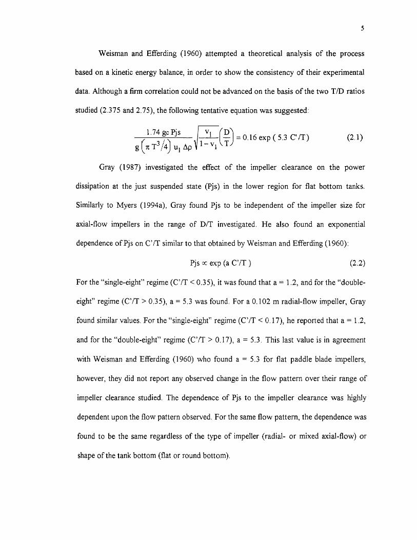
1.74 gc Pjs
g (7t T3 /14) u i Ap
v D\
— v= 0.16 exp ( 5.3 C' (2.1)
5
Weisman and Efferding (1960) attempted a theoretical analysis of the process
based on a kinetic energy balance, in order to show the consistency of their experimental
data. Although a firm correlation could not be advanced on the basis of the two T/D ratios
studied (2.375 and 2.75), the following tentative equation was suggested:
Gray (1987) investigated the effect of the impeller clearance on the power
dissipation at the just suspended state (Pjs) in the lower region for flat bottom tanks.
Similarly to Myers (1994a), Gray found Pjs to be independent of the impeller size for
axial-flow impellers in the range of D/T investigated. He also found an exponential
dependence of Pjs on C'/T similar to that obtained by Weisman and Efferding (1960):
Pjs x exp (a C'/T) (2.2)
For the "single-eight" regime (C'/T < 0.35), it was found that a = 1.2, and for the "double-
eight" regime (C'/T > 0.35), a = 5.3 was found. For a 0.102 m radial-flow impeller, Gray
found similar values. For the "single-eight" regime (C'/T < 0.17), he reported that a = 1.2,
and for the "double-eight" regime (C'/T > 0.17), a = 5.3. This last value is in agreement
with Weisman and Efferding (1960) who found a = 5.3 for flat paddle blade impellers,
however, they did not report any observed change in the flow pattern over their range of
impeller clearance studied. The dependence of Pjs to the impeller clearance was highly
dependent upon the flow pattern observed. For the same flow pattern, the dependence was
found to be the same regardless of the type of impeller (radial- or mixed axial-flow) or
shape of the tank bottom (flat or round bottom).
6
2.1.2 Power Number (Npo)
Rushton et al. (1950) and Bates et al. (1963) reported a general power relationship as a
function of physical and geometrical parameters:
-\ „, w A P vr\(„) i H) h c c') i wb) B (nor oB), (2.3)
Npo = K(Re) (FrrD) ID0) q)) D ) D D J
This relationship contains three basically different parameters: those defining the
boundary conditions and the geometry of the system (T/D, H/D, C'/D, LID, Wb, Ap, W5,
nb, nB); that pertaining to the action of viscosity and gravity (Re); and that which
characterizes the general flow pattern (Fr). This full form is seldom used in practical
power calculation. For the turbulent region, if geometrical similarity is assumed and if no
vortex is present, the Equation (2.3) reduces to:
(Npo = I pN3 D 5 J = constant
This dimensionless group of the power number (Npo) represents an important parameter
in the design of mixing operation.
O'Okane (1974) demonstrated that it was not possible to find values of the
exponents in the generalized power relationship which could be applied to all types of
impellers.
Nienow and Miles (1971) pointed out the considerable effect that minor
dimensions have on the power number, particularly the disk thickness-to-blade height
ratio. As this ratio increases, the friction loss from the inside edge of the blade of the disk
turbine would tend to decrease and therefore so would Npo.
(2.4)
7
Gray et al. (1982) proposed a power correlation for six-blade flat-disk turbine. The
result was a constant power number of 5.17 representing the data for C'/D > 1.1, and
varied with (C'/D)° "29 for C'/D < 1.1. The baffling effect was found to be negligible over
the range of standard size baffling, 1/12 W/T 1/10. The effect of D/T was small under
these conditions.
Rewatkar et al. (1990) found that Npo for the standard disk turbine (D/T = 1/3, C'
= D) and pitched-blade turbine was 5.18 and 1.67, respectively. The Npo was observed to
have a strong dependence on the flow pattern generated by the impellers. In general, Npo
increased for pitched-blade turbine and decreased for disk turbine with a decrease in
clearance. However, in practice, Npo decreased when the clearance was more than T/4
because of surface aeration. Without the effect of surface aeration, the liquid height was
found to have little effect on power consumption. Rewatkar et al. (1990) obtained an
overall correlation for the impeller power number for a pitched-blade turbine:
Npo = 0.653 ( T/D )0.11 (C'/T)-o.23 (n00.680601.82 (2.5)
for: 6 5_ T/D 3, W/D = 0.3, H/T = 1, 0.25 5_ C'/T 0.33, 0.5 5_ A' 5_ 1.05, 4 nb 8
Chang (1993) in his master thesis, conducted an extensive study on the effect of
the impeller clearance on Npo for four types of impellers: six-blade flat-disk turbines
(6FDT), six-blade flat-blade turbines (6FBT), six-blade flat (45°) pitched-blade turbine
(6FPT), and six-blade curve-blade turbine. The agitation system was very similar to the
present work. He studied over a wide range of impeller clearance, including the "single-
eight" and "double-eight" regime. No effect of the D/T (0.264-0.352) and H/T (1-2) ratios
was observed.
8
For the case of the 6FDT, at low impeller clearances (1/6 < C'/D < 1/3) a step
increase in Npo was observed (from 3.34 to 4.30). This was explained as due to the
reduction in the bottom circulation of the disk turbines at low clearances. In the range 1/3
< C'/D < 1, there was a moderate increase in the power number. The reason for this could
be the transition state of flow pattern around in the impeller blades. At CM = 1, the
power number increased to 4.9, while it increased to 5,10 at C'/D = 2.
For the case of the 6FBT, Npo moderately decreased with an increase in the
impeller clearance between 1/6 < C'/D < 1/2. Beyond this range, the rate of decrease was
lower. Furthermore, for C/D = 5/6, Npo reached the minimum value of 2.09.
Similar to the 6FBT, the power number in the 6FPT decreased from C/D = 1/6 to
C/D = 2, values of 1.90 and 1.34 were found, respectively. The higher values of Npo at
low impeller clearance was due to the throttling effect of the bottom tank.
2.1.3 Change of Flow Pattern
Conti et al. (1981) noted that by lowering C', the hydrodynamic regime changed from one
with large vortices above and below the impeller (the so-called double-eight figure) to that
where the lower vortices were absent (single-eight). The value of C' at which the change
occurred was always equal to about 0.22 T in the various systems examined, this value
was practically independent of either Njs or D/T (0.22 < D/T < 0.37). The power decrease
at C'/T = 0.22 was very considerable. The results showed that the dissipated power and
the minimum impeller velocity, for complete suspension of the solids, were strongly
dependent on the hydrodynamic regime.
9
Gray (1987) also found that the dependence of the power on the type of impeller
was highly dependent upon the pattern observed. For the same flow pattern, the
dependence was found to be similar for each type of impeller (radial or axial). The change
in the flow pattern was found to be independent of the D/T ratio over the limited range
studied. For disk impellers, the pattern change was found to occur at C'/T = 0.22 as found
by Conti et aL (1981) for eight-blade flat-blade disk turbine agitating in flat bottom tanks.
For six-blade flat-blade impellers, the flow pattern changed at C'/T = 0.17, similarly to
that observed by Nienow (1968), for six-blade flat-disk impellers. Axial-flow impellers
maintained the "single-eight" flow pattern for propellers up to C'/T = 0.35 in a flat bottom
tank. Zwietering (1958) observed the "single-eight" flow pattern for propellers up to C'/T
= 0.4, Round bottom tanks help to promote the "single-eight" pattern and for this study,
the "single-eight" pattern was observed at C'/T values as high as 0.67.
Armenante and Li (1993) noted that for the case of one radial-flow impeller the
flow pattern below the impeller was a function of the impeller clearance of the tank
bottom. For low C'/T values (corresponding to C'/T < 0.21), the flow pattern was
observed to be swirling outwards so that the particle suspension occurred from the
periphery of the tank. For high values of C'/T (corresponding to C'/T > 0.26), the swirling
action turned inward, and solid suspension occurred from the center of the tank bottom.
For intermediate values of C'/T, a transition region consisting of an unstable flow pattern
was noticed. The range in which the presence of the transition region occurred (0.21 <
C'/T < 0.26) was independent of the presence of additional impellers, at least if the
distance between impellers was kept equal to the impeller diameter.

10
2.2 Effects of Impeller Diameter, Tank Diameter, and Solids Loading
There has been a number of publications dealing with solids-suspension during the past 40
years. Unfortunately, the results obtained on the effect of the impeller diameter(D), tank
diameter (T), and solids loading (X) are different and can be confusing.
The exponent on the impeller diameter (constant tank diameter) found in the
literature varies between -1.16 (Raghava Rao et al., 1988b, mixed axial-flow impellers) to
-2.45 (Zwietering, 1958, radial-flow impellers), depending on the type of impeller and the
experimental conditions used. Baldi et al. (1978) reported a theoretical value of -1.67, for
disk turbines, using Kolmogoroff's theory of isotropic turbulence.
Raghava Rao et al. (1988b) presented an explanation on a rational basis, to
understand the effect of impeller diameter on the solid suspension for different designs of
impellers. For the case of radial-flow impellers, the solids suspension occurs because of
the liquid velocity and turbulence. The turbulence intensity decays along the length of the
flow path [ (T/2) - (D/2) + C' J. With an increase in the impeller diameter, less decay in
the turbulence will occur and the liquid velocity (— D 716) will increase. The overall effect of
increased liquid velocity and the lesser decay in turbulence makes the dependence on
impeller diameter very strong. For the case of a pitched-blade turbine downflow impeller,
the solids suspension occurs mainly because of the liquid flow generated by the impeller.
The average liquid velocity is proportional to ND. Therefore, Njs should be inversely
proportional to D. In this case, it is obvious that the length of the liquid path will not
change appreciably with changes in the impeller diameter, because the liquid flow is
downward directly from the impeller.
11
The dependence of the tank diameter is also expressed in a power form. For the
minimum agitation speed reported values of the dependence at constant impeller diameter-
to-tank diameter ratio lies between those reported by Baldi et al. (1978): -0.5 (C/D = 0.5)
to -0.89 (C/D = 1).
Chudacek (1986) reported values between -0.56 to -0.86, depending of the type of
impeller, tank bottom shape, and suspension criterion. Raghava Rao et al. (1988b)
reported an exponent of 0.31 for the case of constant impeller diameter for 6FPT. They
also explained on a rational basis the effect of the tank diameter.
Einenkel (1980) reported values of the exponent for the power per unit volume
dependence on the tank diameter, scale-up parameter. These values vary between -0.7 to
0.5. For a scale-up factor of 10, these extreme values represent a difference in power per
unit volume by a factor of 15.8. Chudacek (1986) investigated the relationship between
solids suspension criteria, mechanism of suspension, tank geometry, and this exponent.
The results indicated that this scale-up parameter is not constant and depends on the
mechanism of suspension.
Values of the exponent in the dependence of the minimum agitation speed on the
solids concentration fall into two groups: in the range 0.13 to 0.18 for low and moderately
concentrated suspensions, and zero for highly concentrated suspensions. (Chudacek,
1986). The reason for the discrepancy at lower concentration can be explained from the
statistical chance factor involved. The probability, for the suspension of the solids is less,
for lower concentrations, and is higher for higher concentrations. This probability factor
must be a function of solids concentration (Narayanan et al., 1969).

12
2.3 Effects of Other Variables
Liquid level exhibits a negligible effect on the minimum agitation speed (Zwietering,
1958), and on the power requirements (Weisman and Efferding, 1960), unless impeller
placement is such that the flow pattern is significantly affected by phenomena such as air
entrainment (Myers et al., 1994a).
Installing baffles destroys the vortices and promotes a flow pattern conductive to
good mixing (Oldshue, 1983). The standard baffles, four vertical baffles (1/12 to 1/10 the
tank diameter in width), provide conditions which are conductive to top-to-bottom
turnover, and the elimination of vortices. Based on the suspended slurry height, Weisman
and Efferding (1960) recommended to set the baffle off-bottom clearance one-half of the
impeller diameter (BC = 0.5 D), for six-blade paddle impellers. Myers and Fasano (1992)
suggested that all highly tangential flow impellers would particularly benefit setting the
baffle off-bottom clearance, one-fourth to one-half of the baffle width. The change in
baffle design would have a negligible effect on power draw characteristics.
Increasing the number of blades produces an increase in efficiency. Chapman et al.
(1983) reported that increasing the number of blades from four to six on an mixed flow
impeller pumping down (D/T = 0.25), slightly lowered the power (— 13%) and speed (-
9%) to just suspend a 1% concentration of soda glass ballotini.
Raghava Rao et al. (1988b) studied the effects of blade width and thickness, for
pitched-blade downflow turbines. For the blade width, they found a minimum value of Njs
at 0.35 D. The value of Njs slightly decreased with an increase in the blade thickness;
while keeping the other design parameter constant the power increased.
13
Inclination of blades also plays an important role in solids suspension. For a blade
inclination angle (a) of 30°, the radial flow rate may be considered insignificant. For a
blade inclination of 45°, however, radial volumetric flow rate becomes significant (Musil et
al., 1984).
The effect of the particle size (dp) on the minimum agitation speed seems to
depend of the hydraulic regime and the range of the particle size. The value of the
exponent on the particle size lies between the theoretical values of 0.66 for laminar settling
of particle and 0.16 for turbulent settling (Chudacek, 1986). Myers et al. (1994b), for all
the data in the range examined (85-19100 1.1m), found an exponent of 0.20 similar to that
of Zwietering (1958).
Myers et al. (1994b), similarly to Zwietering, also found that for mixed axial-flow
and axial-flow impellers, the dependence on the dimensionless density was :
Njs cc p pi )o.45 (2.6)
The dimensionless density was varied over three-hundred fold, from 0.0060 to 1.91. This
dependence seems to be the most accepted. Nienow (1968) reported an exponent of 0.43,
and Narayanan et al. (1969) an exponent of 0.5.
The experiments in the turbulent region confirm the negligible effect of viscous
forces. The dependence of the minimum agitation speed on the viscosity (v) is reported as
exponents in the range of 0.1-0.2.
The exponents of the variables: liquid viscosity, solids-liquid density difference,
particle size, and solids concentration have been found to be independent of impeller
clearance (Zwietering, 1958; Raghava Rao et al., 1988b).
14
2.4 Mechanisms of Suspension
A comparison of the suspension ability on the basis of suspension mechanism has been
reported in the literature. For the case of the radial impellers, the suspension is attributed
to random turbulent bursts (Baldi et al., 1978, Chapman et al., 1983). Raghava Rao et al
(1988b) state that a decrease in clearance results in the decrease of the path length; this
decrease causes a dual effect: decay of turbulence along the flow pattern reduces and the
liquid velocity is increased. Open impeller types (without the disk) do not normally pump
in a truly radial direction, since there is a pressure difference between each side of the
impeller. They tend to pump upward or downward while discharging radially (Oldshue,
1983). Because of the more uniform radial flow pattern, disk impellers tend to draw more
power than open impellers, which affect the economy of their application.
Since the axially discharging impellers are more efficient than radially discharging
impellers, producing higher flow but lower turbulence intensity, Chudacek (1985)
speculated that the flow and not the shear rate controls the suspension of solids for this
type of impeller. An alternative explanation might be that the path length between the
impeller and the point from which particles are last suspended is less for an axial-flow
impeller, reducing the probability of the turbulent eddies decaying (Chapman et al., 1983).
This type of impellers produces a flow that leaves the impeller tip, hits the vessel, scours
the bottom, and lifts the particles from the periphery. At very low impeller clearance, the
impeller stream hits the vessel bottom with higher velocity causing a sharp change in flow
direction, which dissipates more energy, increasing the power consumption and power
number (Raghava Rao and Joshi, 1988a).
15
2.5 Effect of Multiple Impellers
Very little effort has been directed towards understanding the effect of multiple impellers
on solid-liquid agitation. Weisman and Efferding (1960) attempted to study the effect of
two impellers, and recently Armenante et al. (1992) and Armenante and Li (1993)
conducted experiments to study the effect of two and three radial-flow impellers. They
found that in many situations the presence of multiple impellers reduced the minimum
agitation speed requirement to produce the just suspended state, but the power
consumption required for this purpose was significantly higher than that measured for
single impellers.
Armenante et al. (1992) found that the dependence of Njs on the impeller diameter
does not change too significantly with the number of impellers mounted on the shaft.
However, the clearance of the lowest impeller off the tank bottom plays a major role.
Later, Armenante and Li (1993) found that the region in which the change of flow pattern
occurred is not influenced by the presence of multiple impellers. They also observed that a
near linear relationship exists between Njs and the ratio C'/D (constant T), for the case in
which one impeller is used. However, the same does not apply when two impellers were
present. The lower impeller consumes slightly less power than the top one, but this
difference disappeared as C'/D increased. Njs was only a weak function of the spacing
between the impellers. The results obtained led to the following conclusions:
- The impeller closer to the bottom is primarily responsible for generating a suspension.
- The presence of additional impellers may result in a flow pattern interfering with the
primary low pattern of a single impeller, thus demanding higher agitation requirements.
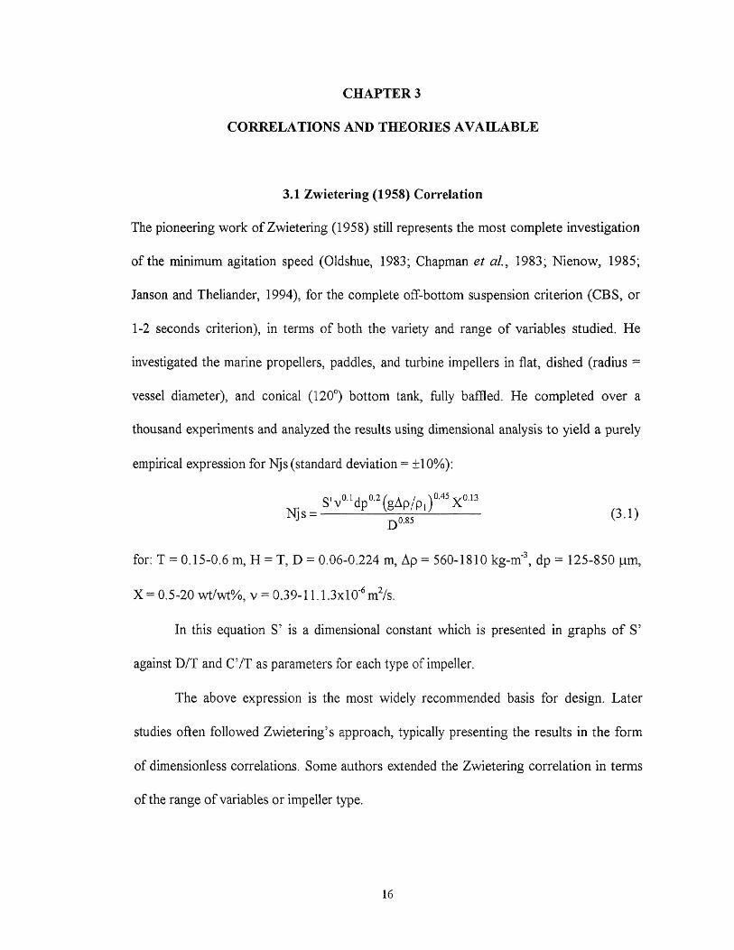
Njs =D°.85
v 0.1 dp 0.2 (gAp/p )0.45 X°'3
(3.1)
CHAPTER 3
CORRELATIONS AND THEORIES AVAILABLE
3.1 Zwietering (1958) Correlation
The pioneering work of Zwietering (1958) still represents the most complete investigation
of the minimum agitation speed (Oldshue, 1983; Chapman et al., 1983; Nienow, 1985;
Janson and Theliander, 1994), for the complete off-bottom suspension criterion (CBS, or
1-2 seconds criterion), in terms of both the variety and range of variables studied. He
investigated the marine propellers, paddles, and turbine impellers in flat, dished (radius —
vessel diameter), and conical (120 0) bottom tank, fully baffled. He completed over a
thousand experiments and analyzed the results using dimensional analysis to yield a purely
empirical expression for Njs (standard deviation = ±10%):
for: T = 0.15-0.6 m, H = T, D = 0.06-0.224 m, Ap = 560-1810 kg-m' 3 , dp = 125-850 !lin,
X = 0.5-20 wt/wt%, v = 0.39-11.1.3x10 -6 m2/s.
In this equation S' is a dimensional constant which is presented in graphs of S'
against D/T and Cif as parameters for each type of impeller.
The above expression is the most widely recommended basis for design. Later
studies often followed Zwietering's approach, typically presenting the results in the form
of dimensionless correlations. Some authors extended the Zwietering correlation in terms
of the range of variables or impeller type.
16
17
Nienow (1968) extended the range covered for the density difference, particle size,
and concentration, for the disk turbines. Chapman et all (1983) used two criteria (CBS
and concentration measurements near the base) to investigate the effects of particles and
liquid properties, tank diameters, and impeller type (radial and mixed-flow).
Chudacek (1985) analyzed phenomenologically in detail the solids suspension in
the classical flat bottom tank. A fully profiled bottom and a "cone and fillet" bottom tanks
were used as alternatives geometries. Chudacek (1986) made an extensive experimental
work showing the relationship between solids suspension criteria, mechanism of
suspension, tank geometry, and scale-up parameters.
Raghava Rao et al. (1988b) studied systematically the critical impeller speed for
solid suspension using pitched-blade turbines. They extended the number of variables
investigated by including the effect of blade width and blade thickness. Myers et al. (1992)
using an innovative video technique investigated the influence of baffle off-bottom
clearance on the solids suspension of pitched-blade and high efficiency impellers. Later,
Myers et al. (1994b) studied the influence of solid properties on the just suspended
agitation requirements of the above impellers. The general trends found in these studies
confirmed the results obtained by Zwietering and the validity of his correlation.
None of these published correlations predicts the effect of impeller position from
the tank bottom. Only recently, Aravinth et al. (1996) proposed a new correlation for
6FBT, in which the power form was used to quantify the effect of the impeller clearance.
However, the maximum deviation between experiments and the regression curve was
19.2%.
18
3.2 Baldi et al. (1978) Theoretical Model
Published suspension theories can be divided into six groups according to the presumed
suspension mechanism (Rieger and Ditl, 1992):
1. The first group is composed of those theories based on the balance between energy
dissipated by the settling particles and the energy dissipated in the fluid by the agitator.
The theories presented by Kolar (1961) and by Musil and Vlk (1978) were based on
this hypothesis. However, these models are based on an energy balance which is not
complete and assumed that the agitation tank is hydrodynamically homogeneous
(Chudacek, 1986). They also assumed that all power is consumed only for solids
suspension (for suspension of low concentration, this assumption is not satisfied). Not
all of the energy terms can be satisfactorily described at present and, even if they could,
their solution would be fairly complex. The energy balance model would therefore
appear to have only a slim chance of success.
2. Another group is composed of those theories based on the presumption that the energy
needed to suspend the particle from the bottom is proportional to that of turbulent
vortices. This group involves the theories presented by Baldi et al. (1978).
3. The third group is composed of theories based on a balance between the upward fluid
velocity and the particle's settling velocity. Narayanan et al. (1969) assumed that the
velocity of ascendant fluid to be equal to the mean fluid velocity, whereas Wichterle
(1988) assumed that the ratio of the velocity within the boundary layer and the settling
velocity of the particles is constant (simplified momentum balance). However, Janson
and Theliander (1994) showed that this ratio is not a constant.

19
4. The fourth group includes the paper published by Molerus and Latzel (1987a). Their
theory concerning the suspension of fine particles (Ar < 40) also rests on the boundary
layer theory, mainly on the balance between the force of a fluid affecting the particles
and the gravity force reduced in buoyancy.
5. The fifth group consists of theories based on the presumption that the agitator must
overcome the pressure difference caused by the differences in particle concentrations in
upward and downward flow. The theory of Molerus and Latzel (1987b) for large
particles (Ar > 40) are based on this presumption.
6. Rieger and Ditl (1992) also report a theory presented for relatively large particle forms.
This theory balances the potential energy necessary to achieve suspension with the
kinetic energy of fluid flow being discharged from the agitator.
Perhaps the most successful attempt to model solids suspension is due to Baldi et
al. (Chapman et al., 1983; Nienow, 1985; Rieger and Ditl, 1992). However, since it is
linked to mean energy dissipation rates and Kolmogoroff's theory of isotropic turbulence,
it is somewhat less realistic from the fluid mechanics point of view (Nienow, 1985). They
assumed that the particles being suspended are picked up by turbulent eddies of a critical
size. In general, these eddies are much larger than the Kolmogoroff scale of turbulence.
This size would be of the order of the particle size because smaller ones would be
insufficiently energetic to achieve suspension; and the low frequencies of arrival of larger
eddies would reduce their chance of achieving it. An energy balance could then be
performed on the basis that the kinetic energy imparted by the eddies was proportional to
the potential energy gained by the particle.

20
This energy balance led to the specification of a dimensionless group (Z), which
was related to the ratio of the energy dissipated on the tank base ([e T]B), responsible for
suspension, to the average energy dissipation in the tank (e T), i.e., for cylindrical vessels of
liquid height equal to the tank diameter:
dp 1/6 T(gAp/p ) 1/2
ZNpo 1/3 D 5/3 Nis
If [eT] B is proportional to eT, then it implies that Z is a constant. However, Baldi et al. also
considered that [eT]B/eT ratio actually depends on the fluid properties especially viscosity
and on the impeller size, position, and type. Therefore:
Z = f (Rem, T/D, C/D, impeller type) (3.3)
where, by analogy with the decay of turbulence downstream from a grid so that:
D 3 Nj s Rem = (3.4)
vT
Experimental data obtained with eight-blade flat-disk turbine, at constant C'/D and
independently from the ratio D/T, showed Z to follow the relation:
Z oc Remn (3.5)
The dependence of Njs on solids loading (X), was not accounted for in the model, but was
obtained empirically from experiments (Z cc Km), and agreed very close with Zwietering's
relationship. Nevertheless, assuming that the above relationship is known, an expression
for Njs can be deduced from their work:
vnAn-F1) (gAp /p1 )1/(211+1) dp 11(6n-1-6) TxmAn+i)Njs oc D (5+90(3n-f-3)Npo von+3)
(3.2)
(3.6)
21
(3.7)
(3.8)
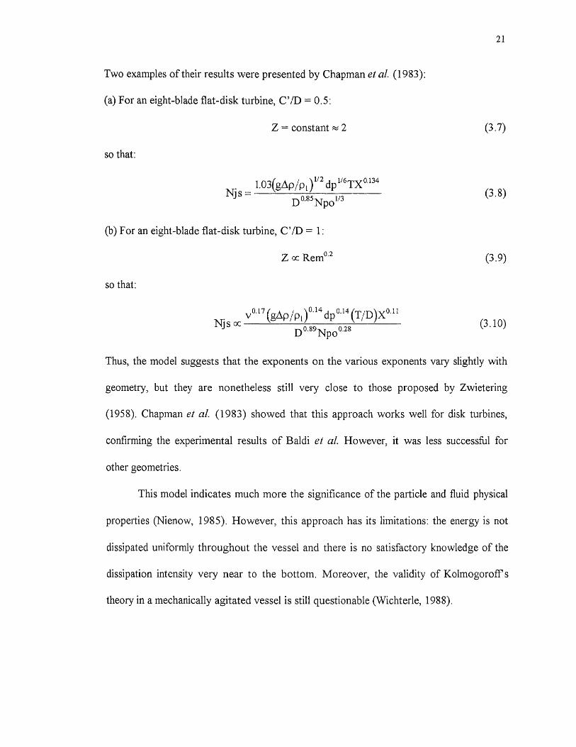
Two examples of their results were presented by Chapman et al. (1983):
(a)For an eight-blade flat-disk turbine, C'/D = 0.5:
Z constant N 2
so that:
1.03(gdp/p )1/2 dp1/6Tx0.134Nj s =
D m ll3Npo
(b) For an eight-blade flat-disk turbine, C'/D = 1:
Z oc Rem°.2 (3.9)
so that:
v0.17 (gAp ipi \ 0•14dp 0.14 (T/D)X °. "
Njs oc (3.10)D 0.89Npo 0.28
Thus, the model suggests that the exponents on the various exponents vary slightly with
geometry, but they are nonetheless still very close to those proposed by Zwietering
(1958). Chapman et al. (1983) showed that this approach works well for disk turbines,
confirming the experimental results of Baldi et al. However, it was less successful for
other geometries.
This model indicates much more the significance of the particle and fluid physical
properties (Nienow, 1985). However, this approach has its limitations: the energy is not
dissipated uniformly throughout the vessel and there is no satisfactory knowledge of the
dissipation intensity very near to the bottom. Moreover, the validity of Kolmogoroff's
theory in a mechanically agitated vessel is still questionable (Wichterle, 1988).
22
3.3 Conti et al. (1981) Correlation
Extending the theoretical model of Baldi et al., Conti et al. (1981) proposed empirical
correlations for eight-blade flat-disk impellers in which the dimensionless grouping Z, was
found to increase in value linearly with increasing impeller clearance. Two correlations
were given dependent upon the flow pattern observed.
Following the approach of Baldi et al., the experimental results by Conti et aL
were interpreted on the basis of the dimensionless numbers Z, Rem, Npo, C/D, T/D, and
X. When all the other parameters were constant, they found that the relation between Z
and X could be expressed as:
z x0.134CC constant (3.11)
Further, Z r 134 was found to be independent of D. Hence they proposed the following
relation:
Z x0.134 = f ( Rem*Npo, C'TT ) (3.12)
Using the experimental values for Njs and Npo, they found that the following expression
gave the best correlation:
Z x0.134= a (Rem*Npo) + b
where: for C'/T < 0.22 (Npo = 5.5):
a = 2.08E-5 - 6E-5 C'/T
b 0.575 - 1.25 C'/T
and for C'/T > 0.22 (Npo = 8):
a = 1.70E-5 - 4.55E-5 C'/T
b = 0.21
(3.13)
(3.14)
(3.15)

CHAPTER 4
EXPERIMENTAL EQUIPMENT AND PROCEDURE
4.1 Experimental Set-Up
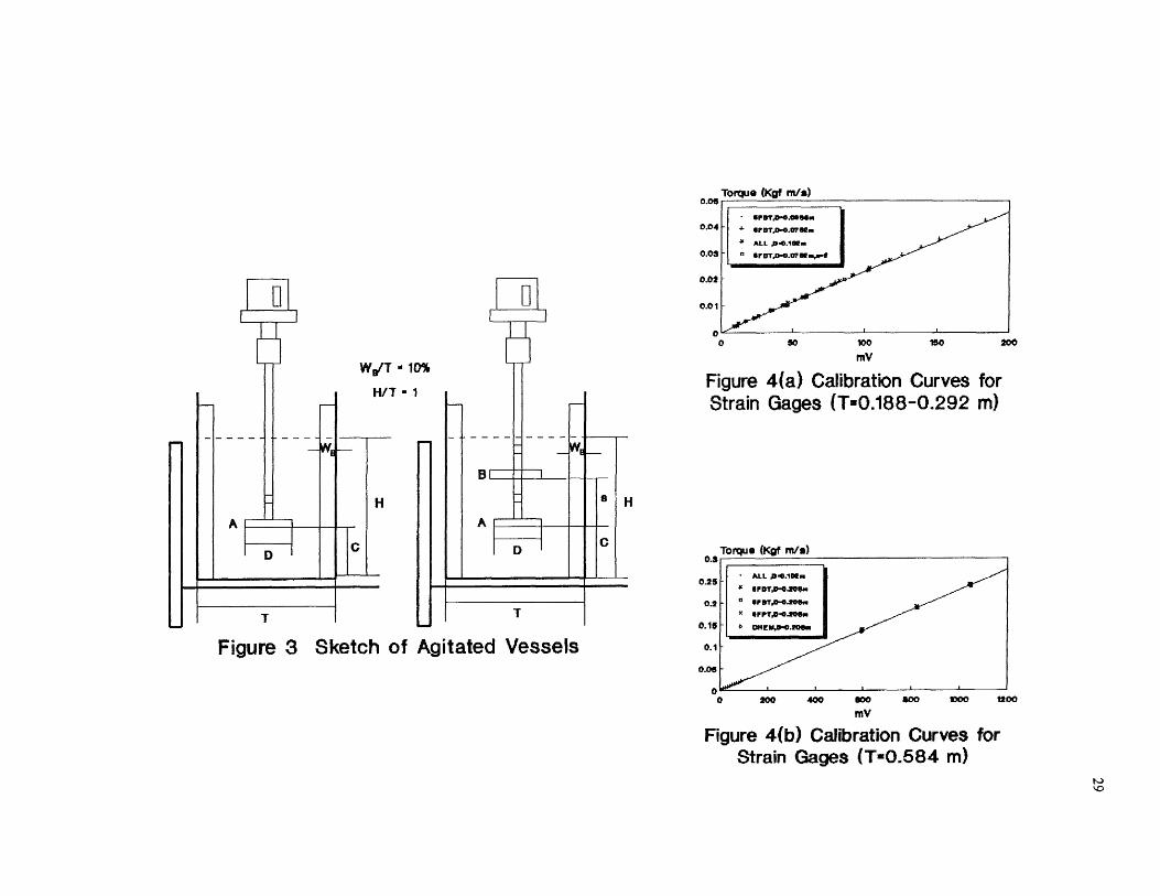
The experimental set-up is shown in Figure 1. The solids suspension experiments were
carried out in open, flat bottomed, cylindrical vessels. Four tank sizes were used: 0.188 m,
0.244 m, 0.292 m, and 0.584 m. The material of construction of these tanks was
Plexiglass. All the tanks were equipped with four baffles of standard width and equally
spaced. Since the main aim was to analyze the effect of the impeller clearance very near to
the tank bottom, the baffles were extended until the bottom. The vessels were located on a
tank support system that could be moved vertically so as to change the distance between
the (fixed) shaft with the impellers mounted on it and the tank bottom. Table 1 gives the
details of the vessel dimensions.

1
TACHOMETER
SLIP RING
STRAIN GAGE CONDITIONER
SUPPORT
00 00 0
0 0 0
CONTROLLER
••. ..... ..••••..•-•• """"
r 1
COMPUTER
MOTOR
INTERFACE
IMPELLER
BAFFLES
AGITATED VESSEL
Figure 1 Experimental Set-Up
STRAIN GAGE
TANK SUPPORT SYSTEM

25
The tanks were filled with tap water up to a liquid height equal to the tank
diameter. The air bubbles were eliminated by agitating the water and cleaning inside the
wall of the tanks. The temperature was measured in each experimental run, the average
value being 22±0.5 °C. The solid phase was made of glass beads (Superbrite, 110-5005),
having a particle size of 110 p.m, and density of 2500 kg/m 3 . A concentration of 0.5
wt/wt% was used in the majority of the experiments. Additionally, the effect of the solids
loading was studied using 1.0 and 1.5 wt/wt% of concentration in the 0.292 m tank, for
each type of impeller (0.102 m impeller size). The solid and liquid phases were changed
frequently to maintain them "clean", at least after three experimental runs.
Four types of impellers were investigated, namely, six-blade flat-disk turbine
(6FDT), six-blade flat-blade turbine (6FBT), six-blade flat (45°) pitched-blade turbine
(6FPT), and the high efficiency impeller Chemineer HE-3 (CHEM). For the radial-flow
impellers (6FDT and 6FBT) and the mixed axial-flow impeller (6FPT), four sizes were
used: 0.0635 m, 0.0762 m, 0.102 m, and 0.203 m. For the axial-flow impeller (CHEM),
five sizes were used: 0.102 m, 0.114 m, 0.178 m, 0.203 m, and 0.229 m. All the impellers
present standard design, except for the 0.0635 m 6FPT impeller. This impeller was made
from a 0.0762 m 6FPT impeller by reducing the length of the blades. The dimensions of
the impellers used in the tank of 0.188 m, 0.244 m, and 0.292 m diameter are shown in
Table 2(a), and those used only in the tank of 0.584 m are shown in Table 2(b). Figure 2
shows schematically the geometry of the impellers. From the tables, it can be observed
that strict geometrical similarity could be kept only for the major dimensions due to the
techniques of manufacture. Some minor dimensions change can be noticed.
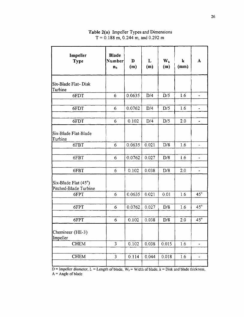
Table 2(a) Impeller Types and DimensionsT = 0.188 m, 0.244 m, and 0.292 m
26
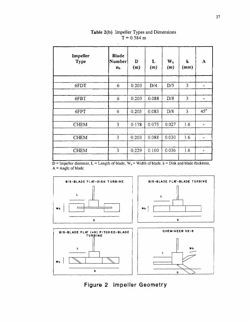
Table 2(b) Impeller Types and DimensionsT = 0.584 m
27
28
The rotational speed was measured with an optical tachometer with a light sensor
(Cole Parmer Instrument Co.), accurate within ±1 rpm. The power was provided to the
impeller by a 2.0 HP variable speed motor (G. K. Heller Corp.) with a maximum speed of
1,800 rpm, which rotated a centrally mounted hollow aluminum shaft (length of 83.8 cm).
To avoid lateral motion, the stationary slip ring was supported by a metal frame.
The hollow shaft was equipped with strain gages (Measurements Group Co.,
Raleigh, NC, CEA-06-187UV-350), which allowed the use of one or multiple impellers
(up to three). Metal collars having a length of 2.54 cm, an internal diameter equals to O.D.
of the shaft and an external diameter equal to the bore diameter of the impellers were
mounted onto the shaft. These collars could be moved along the shaft between two strain
gages. The arrangement allows the impellers to be mounted on the shaft without touching
the protruding strain gages, and enabled the impeller collar assemblies to be moved along
the shaft, thus permitting to vary the distances between them. A sketch of the agitation
vessel is shown in Figure 3. The system is very similar to those used by Armenante et al.
(1992), Chang (1993) and Armenante and Li (1993).
The strain gages were connected to a slip ring assembly (Electronics Co.,
Bayonne, NJ) with insulated lead wires passing through the hollow core of the shaft. The
gage signal was picked-up by an external gage conditioner and amplifier system (2120A
system, Measurement Group, Co.). A data acquisition system (Labtech Notebook,
Version # 6.3.0, 1991) installed in a computer was used to analyze the gage signal (mV)
from the conditioner, receive the signal from the tachometer, and calculate the power
drawn by each impeller from the product of angular velocity and torque.
0.05 Torque (Kgf m/s)
• IIIF DTM.0.011011s.0.04
+ er DTA.," el"44 ALL p.0.101/..
0.03
o IF OTAI•8.071/1 wort
0.02
0.01
0200
WD/T ■ 1H/T - 1
0%
O 50 100
150mV
Figure 4(a) Calibration Curves forStrain Gages (T-0.188-0.292 m)
•11•=11, we_
C
8 H
B I
HA
D
T T
Figure 3 Sketch of Agitated Vessels
Torque (Kgf m/s)
ALL p.0.1021.
44 If DTP-0104w
0.2
o OF BTA1•43.201510
• ell.PTA141).200i.
0.15
•
OH E KIS0.20emi
0.1
0.05
0O 200 400 800 500 1000
MV
Figure 4(b) Calibration Curves forStrain Gages (T-0.584 m)
of0.3
0.25
1200
30
The sampling frequency of the data acquisition was 30 times/60 seconds and the
representative power drawn was determined by calculating the average of 30 readings.
When two impellers were used, the upper strain gage gave the torque associated with the
two of them. Thus the power consumption of each impeller could be calculated. The
corresponding Npo was calculated using the Equation 2.4 (Rushton expression).
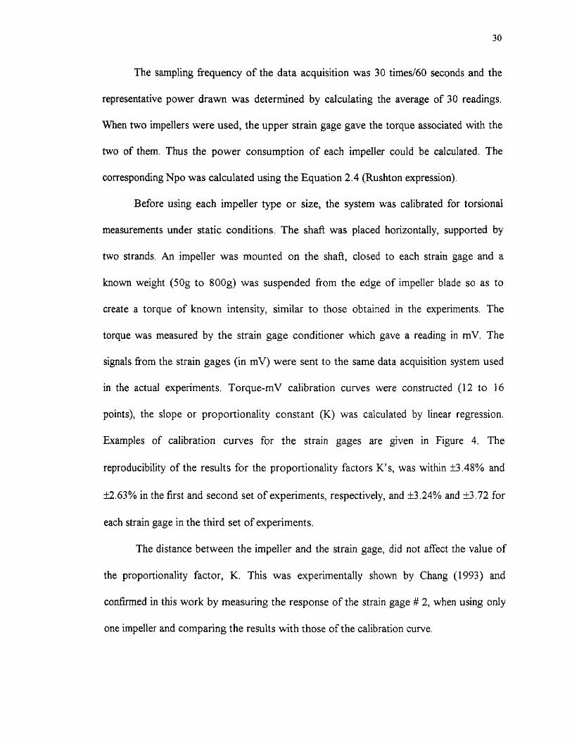
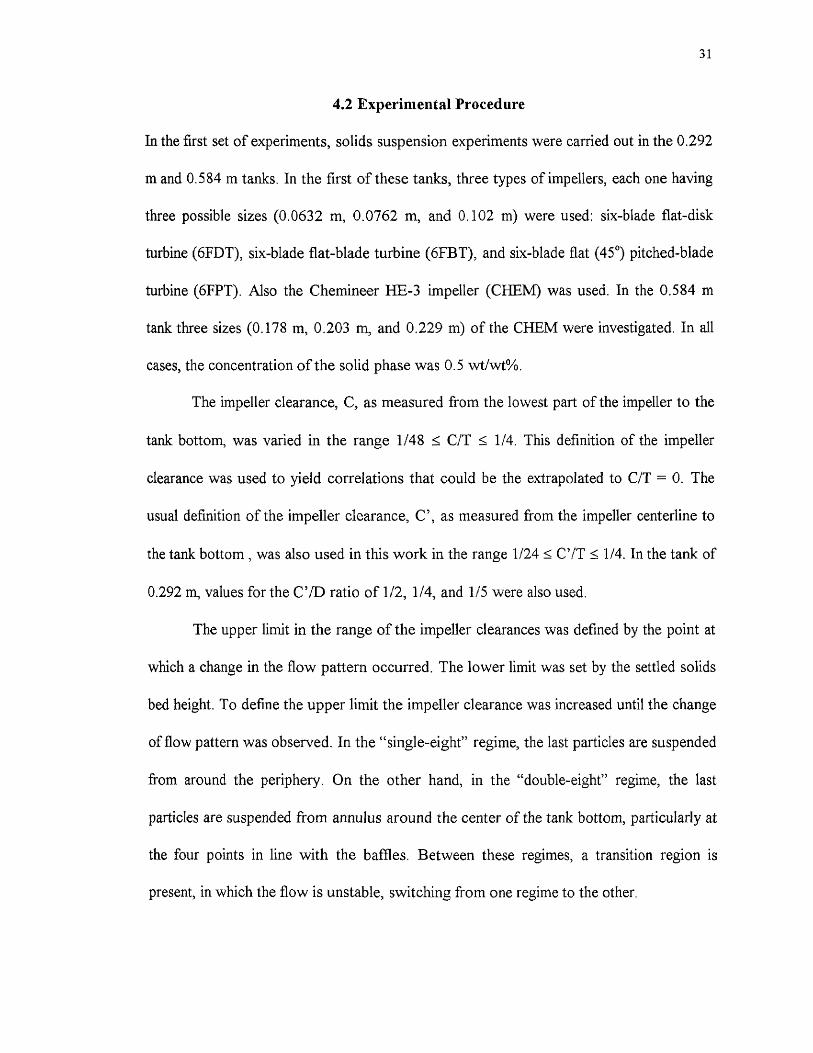
Before using each impeller type or size, the system was calibrated for torsional
measurements under static conditions, The shaft was placed horizontally, supported by
two strands. An impeller was mounted on the shaft, closed to each strain gage and a
known weight (50g to 800g) was suspended from the edge of impeller blade so as to
create a torque of known intensity, similar to those obtained in the experiments. The
torque was measured by the strain gage conditioner which gave a reading in mV. The
signals from the strain gages (in mV) were sent to the same data acquisition system used
in the actual experiments. Torque-mV calibration curves were constructed (12 to 16
points), the slope or proportionality constant (K) was calculated by linear regression.
Examples of calibration curves for the strain gages are given in Figure 4. The
reproducibility of the results for the proportionality factors K's, was within ±3.48% and
±2.63% in the first and second set of experiments, respectively, and ±3.24% and ±3.72 for
each strain gage in the third set of experiments.
The distance between the impeller and the strain gage, did not affect the value of
the proportionality factor, K. This was experimentally shown by Chang (1993) and
confirmed in this work by measuring the response of the strain gage # 2, when using only
one impeller and comparing the results with those of the calibration curve.
31
4.2 Experimental Procedure
In the first set of experiments, solids suspension experiments were carried out in the 0.292
m and 0.584 m tanks. In the first of these tanks, three types of impellers, each one having
three possible sizes (0.0632 m, 0.0762 m, and 0.102 m) were used: six-blade flat-disk
turbine (6FDT), six-blade flat-blade turbine (6FBT), and six-blade flat (45 °) pitched-blade
turbine (6FPT). Also the Chemineer HE-3 impeller (CHEM) was used. In the 0.584 m
tank three sizes (0.178 m, 0.203 m, and 0.229 m) of the CHEM were investigated. In all
cases, the concentration of the solid phase was 0.5 wt/w0/0.
The impeller clearance, C, as measured from the lowest part of the impeller to the
tank bottom, was varied in the range 1/48 C/T 1/4. This definition of the impeller
clearance was used to yield correlations that could be the extrapolated to C/T = 0. The
usual definition of the impeller clearance, C', as measured from the impeller centerline to
the tank bottom , was also used in this work in the range 1/24 C'/T 1/4. In the tank of
0.292 m, values for the C'/D ratio of 1/2, 1/4, and 1/5 were also used.
The upper limit in the range of the impeller clearances was defined by the point at
which a change in the flow pattern occurred. The lower limit was set by the settled solids
bed height. To define the upper limit the impeller clearance was increased until the change
of flow pattern was observed. In the "single-eight" regime, the last particles are suspended
from around the periphery. On the other hand, in the "double-eight" regime, the last
particles are suspended from annulus around the center of the tank bottom, particularly at
the four points in line with the baffles. Between these regimes, a transition region is
present, in which the flow is unstable, switching from one regime to the other.
32
Each run always began at low agitation speed. At each agitation speed, the system
was allowed to reach the steady state (— 10 min.). The speed was increased after each
observation until the point of complete off-bottom suspension was reached.
At a particular speed, some solids are suspended from the tank bottom after
moving vigorously. Increasing the speed the amount of solids suspended increases. When
a particular impeller speed is reached, all the particles move vigorously on the tank bottom
before being suspended. However, they momentarily stop for a while (which is prominent
enough to be noticed) before becoming suspending. With a slight increase in the impeller
speed, this momentarily stoppage of solid particles is eliminated. A similar observation was
described by Raghava Rao et al. (1988b). The position of the suspension of the last
particles depends on the impeller off-bottom clearance as mentioned before.
The complete off-bottom criterion used in the determination of the minimum
agitation speed, was those defined by Zwietering (1958), as the speed at which no particle
was visually observed at rest on the tank bottom for more than one or two seconds. A
mirror placed at 45° under the tank was used for the visual observation. A lamp of 150
watts was used to illuminate laterally the tank bottom.
For some experimental runs, the solids suspension for one value of the impeller
clearance was repeated (ten times), either by decreasing or increasing the agitation speed.
The reproducibility of Njs was less than ±4.22%. While keeping Njs constant, the
measurement of the power dissipation was also repeated. The reproducibility of the power
dissipation was approximately ±6.18%, although occasionally within ±12.79% for gage
signal readings less than 10 mV (accuracy within ±1 mV).

33
The power number (Npo) was calculated using the Equation (2.4), and the
experimental values of Njs and Pjs obtained in the solids suspension. For each value of
impeller off-bottom clearance used, Npo was also calculated using water only (without
solids), at different Reynolds numbers. In this case, the power number was calculated by
taking the average of the values measured at two different speeds (out of the range of
Njs). The objective in this calculation was twofold. First, the value obtained in the solids
suspension was compared with the value obtained using water only. Second, for the case
of using water only, the relation of the power and the agitation speed was also calculated.
Table 3 gives the rotational speeds (N) and the range of Reynolds number (Re) used in the
experimental determination of the power number (Npo) using water only.
Table 3 Experimental Determination of the Power Number (Npo) Using Water Only

34
In the second set of experiments, the effects of the tank diameter and solids
loading were investigated. The effect of the tank diameter was studied in two ways. First,
the D/T ratio was kept constant (D/T = 0.348). For the 6FDT, 6FBT, and 6FPT, the
0,0635m, 0.102 m, and 0.203 m impeller sizes were used in the tanks having a diameter of
0.188 m, 0.292 m, and 0.584 m, respectively. In this case, the conclusions drawn are
applicable for both constant C/T and constant C'/T. Additionally, experiments were
conducted in which the impeller diameter (D = 0.0762 m) was kept constant in the 0.188
m, 0.244 m, and 0.292 m diameter tanks. The conclusions drawn in this case are only
applicable for constant C/T
The effect of the solids loading was investigated in the 0.292 m diameter tank, and
using different types of impellers all having a 0.102 m diameter. Three values of
concentration were used: 0.5%, 1.0%, and 1.5%. Similarly to the first case of the effect of
tank diameter the results are applicable to both constant C/T and constant C'/T.
In the third set of experiments, the effect of the presence of two impellers was
investigated. The lower impeller was always positioned very close to the tank bottom. The
comparison with the case of using one impeller was performed positioning the lower
impeller of the dual-impeller system at the same impeller off-bottom clearance. This set of
experiments was carried out in the 0.292 m tank, using two 0.0762 m impellers of the
same type. The impellers were two 6FDTs, two 6FBTs, or two 6FPTs.
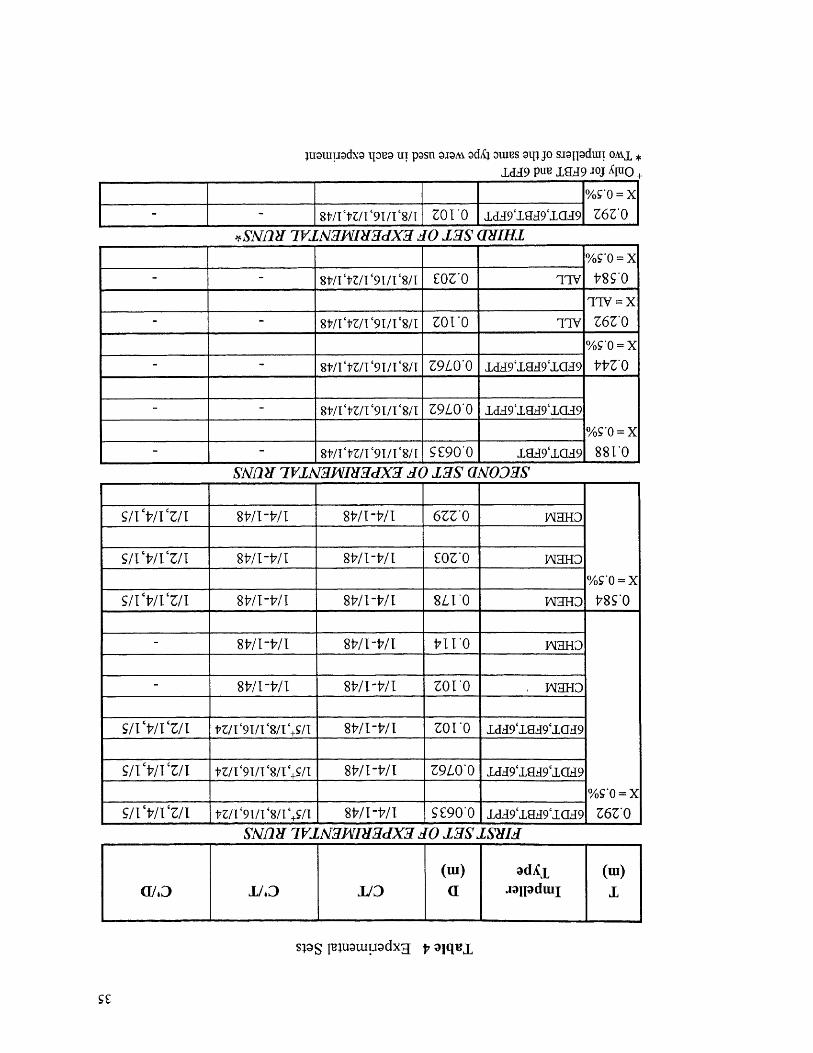
Table 4 summarizes the sets of experimental runs carried out in this work. In each
set the tank size, the impeller type and size, the range of C/T, and the values of C'/T and
C'/D used are shown.
luatupodxa 'pea ui posn aJOM ocIS4 atuus amp siallacku! ones *LID puu ig39 Aitio
Vos'0 = XZ6Z . 0 817/V17Z/1'91/V8n ZO I '0 .1,(139`,La49`,LCI39
*SNIDI 7VINIKnigdXJ JO LIS CIIIIH1%S.0 = X
t8 S'0- 8 t/I '17Z/I '9I/I '8/I £0Z'0 TryTIV = X
Z6Z . 0_ _ 817/1`tZ/1`91/1`8/1 ZOT . 0 Try% g " 0 = X
t17Z . 0_ - 8111'17Z/1'91/1'8/1 Z9L 0 . 0 Id39`,LEL49`1039
%CO = X881'0
- - 817/I '17Z/I '91/1`8/I Z9L0 ' 0 idd9'.1239'ICL49
- - 8t/rtZ/I'9I/e8/I SE90 . 0 Ia49'ICIA9SALIM 7VIAIghlnigdX.7 JO 13S aNO3gS
%co = x
-178 S . 0
S/1 17/I cZ/I WI -t/I 8t7/1 -WI 6ZZ ' 0 1A131-ID
S/r -t7/ ['VI 8t/I- b/ 1 817/1-17/1 £0Z.0 waHD
Sirtil. 'VI 817/1-17/1 8t/I-t/I 8L I . 0 TAIgHD
%S . 0 = XZ6Z*0
- 817/1-17/1 817/1-tin 171 1 . 0 InaHD
_ 817/I-t7/1 817/1-17/I ZO I '0 INaHD
SR ct7/1‘Z/I PZ/e9T/I'8/e+S/1 817/ I - t7/ 1 ZO 1 . 0 Ic139`IELD'ICIA9
Sit '17/1 'Zit nit `9T/I '8/1',S/I 817/I-V/I Z9LO' 0 1a19`,11139`1(1.49
SR 't7/i 'VI la/1'91/1'8/T `+S/I WI -WI S £90'0 1c139`1EL49`,LCE397V1A211111,7dXg JO Igg
C1/3 1/ID 1/D
(ui)a
adiCiaallachui
(w)I
sPS Igluatupodxg t, atqui
SE

CHAPTER 5
RESULTS AND DISCUSSION
5.1 Effect of Impeller Clearance
In the first set of experiments, the effect of the impeller clearance (including very small
clearances) on the minimum agitation speed (Njs), power dissipation at the minimum
agitation speed (Pjs), and power number (Npo) was investigated. The solids suspension
experiments were carried out in the 0.292 m tank, and three type of impellers were used:
six-blade flat-disk turbine (6FDT), six-blade flat-blade turbine (6FBT), and six-blade flat
(45°) pitched-blade turbine (6FPT). In addition, the high efficiency impeller Chemineer
HE-3 (CHEM) was also studied in the 0.584 m tank. In all cases, the power number
(Npo) was also calculated using water only (without solids) at two different Reynolds
numbers. The highest value of the impeller clearance was defined by the region in which
the change of flow pattern occurred. As low as possible impeller clearances, as allowed by
the system geometry or by the settled solids bed height were also used. The impeller
clearance range was 1/48 < C/T <-1/4.
Njs and Pjs were expressed as a function of impeller clearance (C/T), defined as
the distance from the lower part of the impeller to the tank bottom. This definition was
chosen to compare the values of Njs, Pjs, and Npo (calculated using the Rushton
expression) at C/T = 0. When necessary the impeller clearance was .expressed as C'/T (=
C/T + Wt,/2T). A comparison of the effect of C/T on Njs, Pjs, and Npo at constant D/T
ratio, between the different impellers used, is also presented.
36

37
5.1.1 Minimum Agitation Speed (Njs)
In Figure 5(a, b, c, d), the values of Njs have been plotted against C/T, for each type of
impeller. In general, it can be seen that the value of Njs decreases with a decrease in C/T,
for all the impellers. However, for the 6FPT and CHEM impellers with small D/T values,
there is a minimum clearance below which an increase in Njs with lower C/T values is
observed. This phenomenon has been attributed to a "throttling effect" resulting from the
sharp change in flow direction just below the impeller. When D/T is large this effect is not
appreciable, since the wider blades of these impellers produce a higher flow which is not
significantly hindered by the presence of the tank bottom (Chudacek, 1985). In Table 5,
the minimum clearances for Njs, also called optimum clearances, are shown.
Table 5 Optimum Clearances for Minimum Agitation Speed (Njs)
38
Njs was correlated as a function of the impeller clearance. Only the range of C/T in
which Njs decreases with a decrease of C/T was used. Three types of correlation were
analyzed: linear, exponential, and power law. In all cases, the correlation with the power
law was the poorest. This is in agreement with Zwietering (1958) and Chudacek (1986).
Recently, Aravinth et a/. (1996) proposed a new correlation for 61- ,BT, in which the power
law was used to account the effect of the impeller clearance. A maximum deviation of
19.2% was reported. In general, the correlations based on the linear and exponential forms
were similar, the exponential form being slightly superior.
In the literature, there are different opinions about the form of the impeller
clearance dependence on Njs. Conti et al. (1981) proposed empirical correlations for
eight-blade flat-disk turbine, in which Njs can be found as a quadratic function of the
impeller clearance. Musil and Vlk (1978) for conical and truncated cone bottom tanks,
defined two different regions for the effect of the impeller clearance on Njs. The first one
where the impeller clearance had no effect upon Njs, and the second one where a linear
dependence of Njs upon the impeller clearance was observed. According to Baldi et al.
(1978), the influence of the impeller clearance on Njs is more complex. The data reported
by Oldshue and Sharma (1992) indicate a constant value for Njs (0.05 < C'/T < 0.10), for
radial-flow and mixed axial-flow impellers. Armenante et al. (1992) suggested a near lineal
relationship between Njs and the C'/D ratio (0.5 < C'/D < 0.83), for six-blade flat-blade
turbines. The data presented by Myers et al. (1994a) suggested an exponential dependence
of Njs upon C'/T, for mixed axial-flow and axial-flow impellers. The selection of the
exponential form was based on the best correlation over the positive range of Njs.

Li £ t A —: — .o.: /X —
39

40
5.1.2 Power Dissipation at Minimum Agitation Speed (Pjs)
In Figure 6(a, b, c, d), the values of the power dissipation at minimum agitation speed
(Pjs) have been plotted against the impeller clearance for each type of impeller. Similarly
to Njs, the value of Pjs decreases when the impeller clearance decreases. For the case of
the mixed axial-flow (6FPT) and axial-flow (CHEM) impellers, Figures 6(c) and 6(d),
respectively, Pjs seems to be independent of the impeller sizes, as found by Gray (1987)
and Myers (1994a). For the 0.0635 m 6FPT impeller an increase (10%) of the power
dissipation can be seen as compared with the other sizes. This can be attributed to changes
in minor dimensions as will be explained later (See section 5.1.3, Power Number).
From Figures 6(c) and 6(d), it can also be observed that the throttling effect in the
power dissipation is more noticeable than in the case of Njs (the change in flow direction
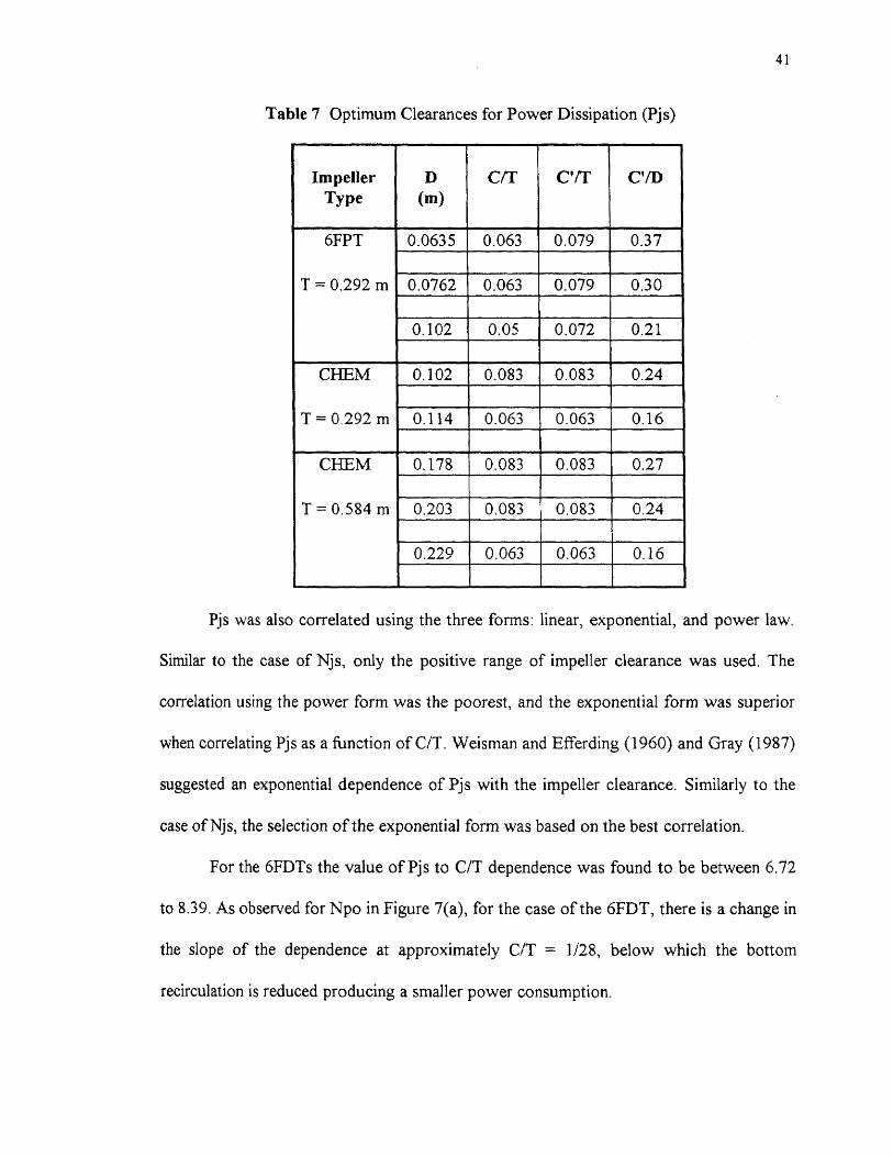
dissipates more energy). Table 7 shows the minimum clearances for Pjs, also referred as
the optimum suspension efficiencies (Chudacek, 1985). Since the throttling effect is not
significant for the case of the radial-flow (6FDT and 6FBT) impellers, they must be
positioned as low as possible for the task of maximum suspension efficiency. For the cases
of the mixed axial-flow (6FPT) and axial-flow (CHEM) impellers, they should be
positioned with minimum clearance, as governed either by the presence of the throttling
effect or by the agitation system geometry. These results support the observation given by
Chudacek (1985), using the complete off-bottom suspension criterion, for three blade
propellers, in different tank bottom geometry. Furthermore, the values shown in Table 7
do not support the current practice of universally positioning the impeller at 0.33 D, for
the task of complete off-bottom suspension.
41
Pjs was also correlated using the three forms: linear, exponential, and power law.
Similar to the case of Njs, only the positive range of impeller clearance was used. The
correlation using the power form was the poorest, and the exponential form was superior
when correlating Pjs as a function of C/T. Weisman and Efferding (1960) and Gray (1987)
suggested an exponential dependence of Pjs with the impeller clearance. Similarly to the
case of Njs, the selection of the exponential form was based on the best correlation.
For the 6FDTs the value of Pjs to C/T dependence was found to be between 6.72
to 8.39. As observed for Npo in Figure 7(a), for the case of the 6FDT, there is a change in
the slope of the dependence at approximately C/T = 1/28, below which the bottom
recirculation is reduced producing a smaller power consumption.
42
For the 6FBTs this value was found to be between 4.74 to 5.30, i. e., in agreement
with Weisman and Efferding (1960) who found a value of 5.3, for flat paddle impellers.
However, Gray (1987) found a value of 1.2 for a six flat-blade impeller in the region of the
"single eight" (C'/T < 0.17), and a value of 5.3 in the region of the "double-eight" (C'/T >
0.17), only one size was investigated in his work.
For the case of the 6FPTs, the exponent of C/T in the expression for Pjs was found
to be between 0.99 to 1,06 in agreement with Gray (1987), who found a value of 1.2, for
flat (45°) pitched-blade impellers. As mentioned before, Pjs for the 0.0635 m 6FPT
impeller shows an unusual increase as compared with the other sizes. However, the
dependence with C/T is similar for all the sizes used, the difference being due to the
experimental error. This suggests that changes in minor geometrical dimensions do not
affect the dependence of C/T on each type of impellers.
For the CHEMs, the exponent of C/T in the expression for Pjs was found to be
between 1.82 to 1.89 in the tank of 0.292 m diameter, and between 1.65 to 1.73 for the
tank of 0.584 m diameter.
The correlations for Pjs are shown in Table 8, for each type of impeller. The
6FDTs present two correlations, depending on the region in which the breakdown on Npo
was observed. For the 6FPT and CHEM impellers, in the region in which the throttling
effect is significant, no attempt was made to find a correlation. From Table 8, the
dependence of Pjs with C/T, follows a relation similar to Equation (5.1) for the case of Njs
(in both comparisons, the presence of only three blades for the CHEM must be noticed):
6FPT < CHEM < 6FBT < 6FDT (5.2)

Table 8 Correlations for Power Dissipation (Pis)
43
44
5.1.3 Power Number (Npo)
In Figure 7(a, b, c, d), the values of the power number (Npo) calculated using the
Equation (2.4), and the experimental values of Njs and Pjs, have been plotted against the
impeller clearance, for each type of impeller. Npo was also calculated using water only
(without solids). In Figure 7, the values of Npo using water only (calculated by taking the
average of the power numbers at two different rotational speed) are also included. A good
agreement between the values obtained can be observed.
For the 6FDTs, Figure 7(a), the power number is nearly constant from C/T = 1/8
to C/T = 1/28. A steep decrease was observed from C/T = 1/28 to C/T = 1/48. This can be
due to the reduction in the bottom recirculation as mentioned before. For the case of
0.0762 m and 0.102 m impellers, the power number seems to be independent of the D/T
ratio. The 0.0625 m impeller shows a decrease in the power number. This could be
attributed to the higher disk thickness-to-blade width ratio (1/8 for this size against 1/10
for the other sizes), which reduces Npo (Nienow and Miles, 1971). Although, all these
observations have been drawn from the plot of Npo against the impeller clearance (C/T) as
defined in this work, similar behavior can be observed by plotting Npo against C'/T (=
C/T + Wb/2T ).
For the case of the 6FBTs, Figure 7(b), the power number shows a slight increase
between C/T = 1/5 to C/T = 1/16. Then a steep increase is observed from C/T = 1/16 to
C/T = 1/48. A minimum value (2.14-2.16), for each impeller size, was observed in the
transition region (C/T > 1/5). In this case, the effect of the D/T ratio is more insignificant.
Again, these observations can also be drawn from a plot of Npo against C'/T .

45
The 6FPTs plot in Figure 7(c) shows the same behavior of the 6FBT, i. e., a slight
increase between C/T = 1/5 to C/T = 1/16 and a steep increase from C/T = 1/16 to C/T =
1/48. The power number seems to be independent of the D/T ratio for the 0.0762 m and
0.102 m impellers. However, contrary to the 6FDT, the 0.0635 m 6FPT shows an increase
in the power number. This could also be attributed to the considerable effect that minor
dimensions have on the power number. In this case, the blade height-to-impeller diameter
ratio is higher for the 0.0635 m 6FPT. A similar increase in the power number has been
reported by Bates et al. (1968) for the 6FBT. An increase of this ratio from 1/8 to 1/5
produce an increase of the power number of approximately 40%.
From Figure 7(d), the CHEMs also show a slight increase in Npo between C/T =
1/4 to C/T = 1/16 and then a steep increase from C/T = 1/16 to C/T = 1/48. In this case, a
slight decrease of the power number with the impeller diameter can be appreciated. All the
impellers present a similar blade thickness (1.6 mm, see Table 2). If the explanation given
above for the case of the disk turbine is applied in this situation, the power number must
increase with the impeller diameter since the blade thickness-to-impeller diameter ratio
decreases. However, this is not the case for this type of impeller, Npo decreases with a
decrease of the blade thickness-to-impeller diameter ratio. This must be due to the
different orientation of the blades (approximately 90° with respect to the disk turbine
blades), the effect of the blade length-to-impeller diameter ratio on the friction loss seems
to be most significant. For this reason, the power number decreases with an increase of the
blade length-to-impeller diameter ratio (LID = 0.37, 0.39, 0.42, 0.43, and 0.43 for D =
0.102 m, 0.114 m, 0.178 m, 0.203 m, and 0.229 m, respectively).
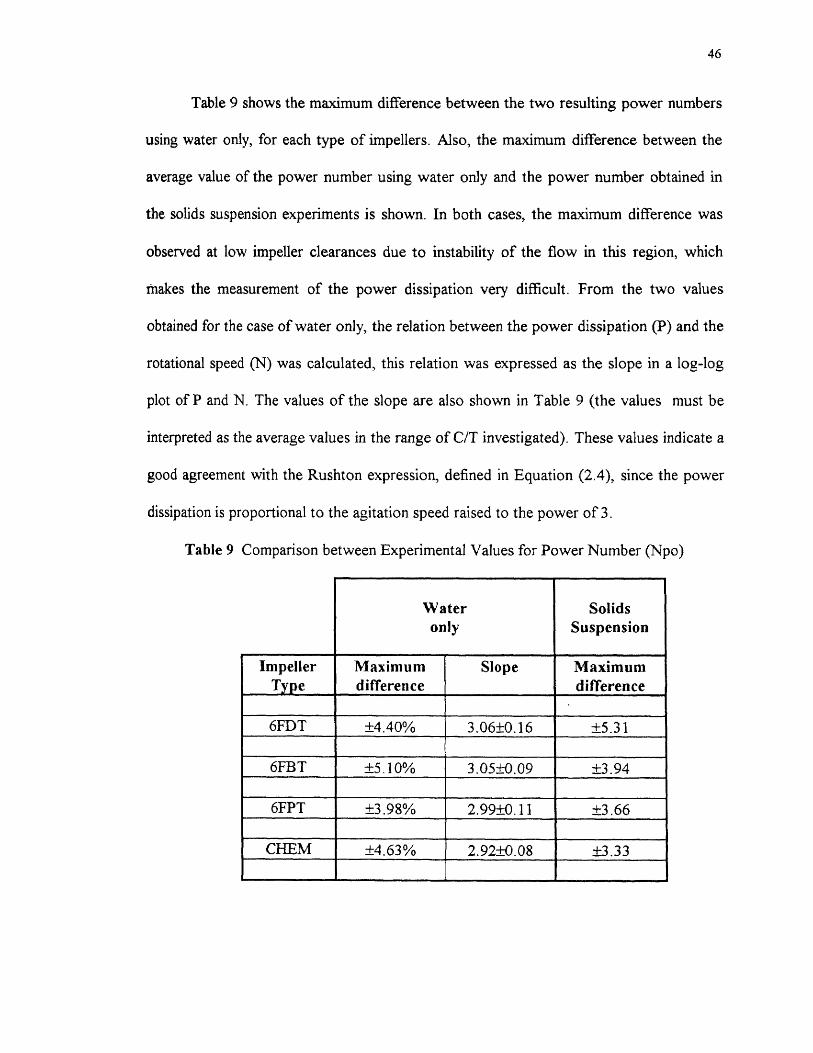
46
Table 9 shows the maximum difference between the two resulting power numbers
using water only, for each type of impellers. Also, the maximum difference between the
average value of the power number using water only and the power number obtained in
the solids suspension experiments is shown. In both cases, the maximum difference was
observed at low impeller clearances due to instability of the flow in this region, which
makes the measurement of the power dissipation very difficult. From the two values
obtained for the case of water only, the relation between the power dissipation (P) and the
rotational speed (N) was calculated, this relation was expressed as the slope in a log-log
plot of P and N. The values of the slope are also shown in Table 9 (the values must be
interpreted as the average values in the range of C/T investigated). These values indicate a
good agreement with the Rushton expression, defined in Equation (2.4), since the power
dissipation is proportional to the agitation speed raised to the power of 3.
Table 9 Comparison between Experimental Values for Power Number (Npo)
Wateronly
SolidsSuspension
ImpellerType
Maximumdifference
Slope Maximumdifference
6FDT ±4.40% 3.06±0.16 ±5.31
6FBT ±5 .10% 3.05±0.09 ±3.94
6FPT ±3.98% 2.99±0.11 ±3.66
CHEM ±4.63% 2.92±0.08 ±3.33

47
The power number was also correlated as a function of the impeller clearance. In
this case, the power law gave the best correlation. Following the Rushton equation (P
N3), the exponent of C/T for the expressions of Pjs (Table 8) must be three times the
values of the exponent of C/T found for Njs (Table 6). This relation is not followed for
these exponents. The difference can be attributed to the C/T dependence of Npo.
The correlations for constant C'/T follow a similar pattern. Since these correlations
will be used later, they are shown in Table 10. The experimental values of Npo obtained in
the 0.188 m and 0.244 m tank sizes were included in these correlations. For the 6FDT,
6FBT, and 6FPT, the values of Npo obtained in the 0.584 m tank size were always higher.
For the 6FDTs, two set of correlations are shown, one for the 0.0635 m impeller
size, and the other for the 0.0762 m and 0.102 m impeller sizes. This is due to the
difference in the disk thickness-to-impeller diameter ratio. Each set of correlation also
presents two ranges of impeller clearance, depending upon the region in which the change
in slope was observed. The correlations in the lower region show a very similar
dependence with C'/T (0.30-0.33) for both sets. The major difference in Npo is observed
in the region in which a constant value for Npo was found (3.92 and 4.21 for the lower
and the higher sizes, respectively). For the 6FPTs, due to the difference in the blade width-
to-impeller diameter, a different correlation for the 0.0635 m impeller was calculated.
However, the dependence with C'/T was similar in both cases. This supports the idea that
minor dimension differences do not affect the dependence with C'/T. Although there is a
slight decrease of Npo with the impeller diameter for the CHEMs, two sets of correlations
are shown depending on the tank size. Graphical comparison is shown in Figure 8.
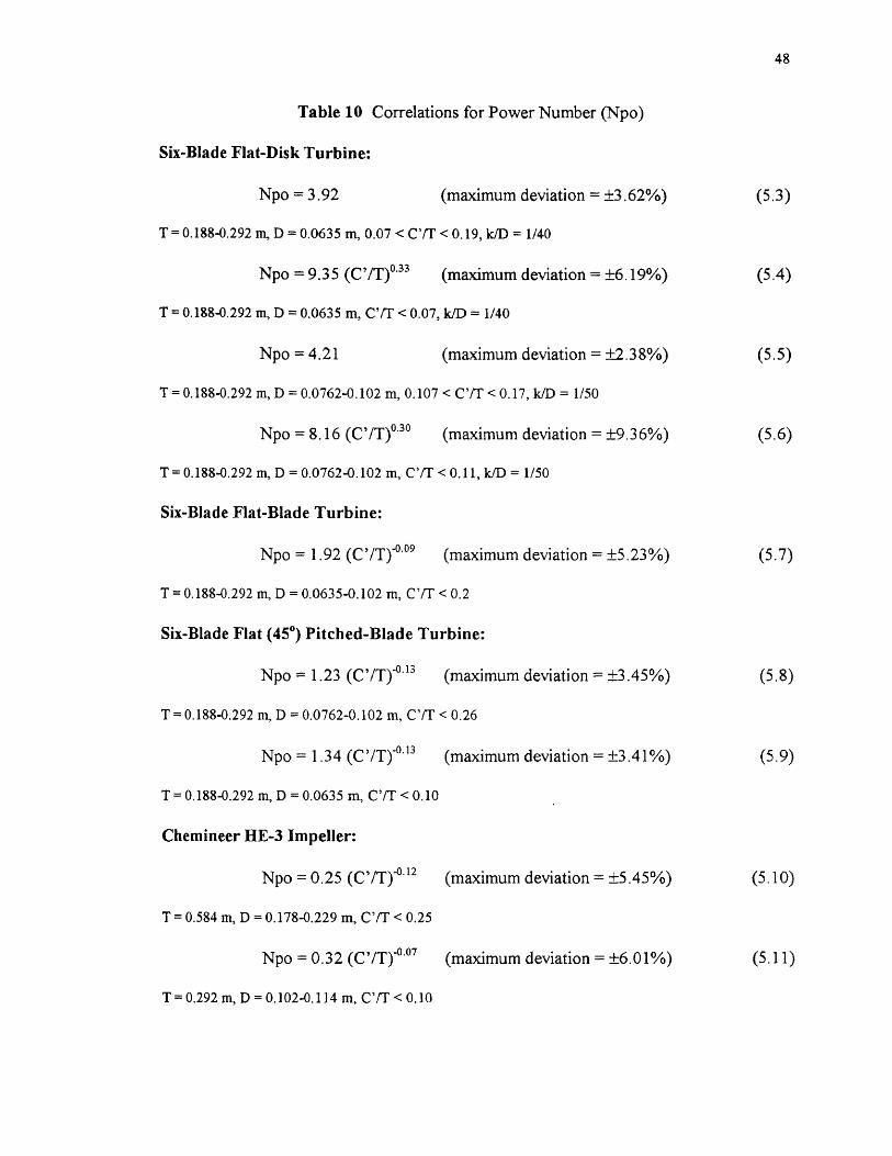
48
Table 10 Correlations for Power Number (Npo)
Six-Blade Flat-Disk Turbine:
Npo = 3.92 (maximum deviation = ±3.62%) (5.3)
T = 0.188-0.292 m, D = 0.0635 m, 0.07 < C'/T < 0.19, k/D = 1/40
Npo = 9.35 (CVT) °33 (maximum deviation = ±6.19%) (5.4)
T = 0.188-0.292 m, D = 0.0635 m, C'/T < 0.07, k/D = 1/40
Npo = 4.21 (maximum deviation = ±2.38%) (5.5)
T = 0.188-0.292 m, D = 0.0762-0.102 m, 0.107 < C'/T < 0.17, k/D = 1/50
Npo = 8.16 (C7T)0.3o (maximum deviation = ±9.36%) (5.6)
T = 0.188-0.292 m, D = 0.0762-0.102 m, C'/T < 0.11, k/D = 1/50
Six-Blade Flat-Blade Turbine:
Npo = 1.92 (C71')"" 9 (maximum deviation = ±5.23%) (5.7)
T = 0.188-0.292 m, D = 0.0635-0.102 m, C'/T < 0.2
Six-Blade Flat (45 0) Pitched-Blade Turbine:
Npo = 1.23 (C/T) -1113 (maximum deviation = ±3.45%) (5.8)
T = 0.188-0.292 in, D = 0.0762-0.102 m, C'/T < 0.26
Npo = 1.34 (Ca) .0.13 (maximum deviation = ±3.41%) (5.9)
T = 0.188-0.292 m, D = 0.0635 m, CUT < 0.10
Chemineer HE-3 Impeller:
Npo = 0.25 (C,a)-0.12 (maximum deviation = ±5.45%) (5.10)
T = 0.584 m, D = 0.178-0.229 m, C'/T < 0.25
Npo = 0.32 (C'/T)4 '" (maximum deviation = ±6.01%) (5.11)
T= 0.292 m, D = 0.102-0.114 m, C'/T < 0.10

49
5.1.4 Change of Flow Pattern
To define the upper limit of the "single-eight" regime, the impeller clearance was increased
until the change of the flow pattern was observed. For instance, the position of the last
particles was carefully observed. As described in Section 4.2, in the "single-eight" regime,
the last particles are suspended from the periphery of the tank bottom, while, in the
"double-eight" regime, the last particles are suspended from an annular space around the
center of the tank bottom.
In general, for the 6FDTs, the change of flow pattern occurred between 0.13 <
C/T < 0.19 (0.16 < C'/T < 0.21), and for the 6FBTs, this change was observed between
0.19 < C/T < 0.24 (0.21 < C'/T < 0.25). In the present work, the range in which the
transition region occurred was a function of the impeller type and size. This is in contrast
with previous authors who found the flow pattern change independently of the D/T ratio.
Nienow (1968) observed the flow pattern change at C'/T = 0.17 for a six flat disk turbine.
Conti et al. (1981) reported the flow pattern change at C'/T = 0.22 for an eight-blade flat-
disk turbine. For a six-blade flat-blade turbine, Gray (1978) reported the flow pattern
change at C'/T = 0.17, and Armenante et al. (1993) found that the transition region
occurred between 0.21 < C'/T < 0.26, independently of the number of impellers.
For the 6FPT and CHEM impellers, the "single-eight" regime was observed up to
C/T = 0.25 (C'/T = 0.26 and C'/T = 0.25, respectively). Zwietering (1958) observed the
"single-eight" flow pattern for propellers up to C'/T = 0.4, and Gray (1978) found that the
mixed axial-flow (6FPT) impellers maintained the "single-eight" flow pattern up to C'/T =
0.35 in a flat bottom tank.

50
Table 11 gives the range of C/T (C'IT), within which the change of flow pattern
was observed for each type and size of impellers. In general, the flow pattern change
occurred earlier for the 6FDT, followed by the 6FBT, and no change occurred up to C/T
= 0.25 for the mixed axial-flow (6FPT) and axial-flow (CHEM) impellers. A similar
sequence (6FDT-6FBT-6FPT, CHEM) has been observed for the minimum agitation
speed (Njs), the power dissipation (Pjs), and the power number (Npo):
Table 11 Change of Flow Pattern Observed in this Work
51
5.1.5 Coinparison of Njs and Pjs at Constant D/T
In Figures 9, 10 and 11, the comparison of Njs, Pjs, and Npo between the different
impellers at D/T ratios of 0.217, 0.261, and 0.348 m are shown, respectively. The
comparison at D/T = 0.348 will be discussed here, since, in this impeller size, the four
types of impellers could be compared. The conclusions drawn at this D/T ratio are also
applicable to the others D/T ratios.
From Figure 9(a), the minimum agitation speed is lower for the 6FDT as compared
with the 6FBT in the "single-eight" flow pattern regime. Njs for the 6FPT is lower than
for the 6FBT until the point in which the throttling effect increases the value of Njs. This
conclusion can be also drawn by comparing Njs for the 6FPT with that for the 6FDT. In
both cases, the value of the impeller clearance in which the tendency is reverted depends
of the impeller size. Similar results can be drawn when the experimental data of Raghava
Rao et al. (1988b) are analyzed. In all the range of impeller clearance investigated, Njs for
the CHEM was higher than for the other impellers. This impeller presents only three
blades against six blades for the other impellers. Chapman et al. (1983) found that
increasing the number of blades reduces both Njs and Pjs.
From Figure 9(b), it can be observed that the power dissipation (Pjs) for the 6FDT
is higher than for the other radial-flow impeller in the major part of the range of impeller
clearances. However, at the point (Ca = 1/28) at which the change in slope for Pjs
occurred, this value is lower than for the 6FBT. The power dissipation for the mixed-axial
flow (6FPT) and axial-flow (CHEM) impellers are lower than those of the radial-flow
impellers. The power dissipation for the 6FPT being higher than that of CHEM.
52
As shown in Figure 9(c), Npo is higher for the 6FDT, followed by the 6FBT. Npo
for the mixed axial-flow and axial-flow impellers are lower than for the radial-flow
impellers. Npo for the CHEM being lower than for the 6FPT.
At very small impeller clearances, 6FDT produces a flow pattern that scours the
base and is efficient for suspension (Nienow and Miles, 1978). For this type of impeller the
suspension is due to the random turbulent bursts (Baldi et al., 1978; Chapman et al.,
1983). Since the path length is reduced, the performance improves at very low impeller
clearance (Raghava Rao et at 1988b). However, it seems that only a part of the energy
supplied by the lowest half part of the impeller is available for the solids suspension, the
power consumption is higher than the mixed-axial flow and axial-flow impellers power
consumption. The behavior of the 6FBT seems to be between the 6FDT (radial-flow) and
the 6FPT (mixed axial-flow). Because of the more uniform radial-flow pattern, 6FDT tend
to draw more power than 6FBT (Oldshue, 1983).
The 6FPT produces a flow that leaves the impeller tip, hits the vessel, scours the
bottom, and lifts the particles from the periphery. At very low impeller clearances, the
impeller stream hits the vessel bottom with higher velocity causing a sharp change in flow
direction which dissipates more energy (throttling effect), increasing the power
consumption and power number (Raghava Rao and Joshi, 1988a). The same mechanism
can be applied for the CHEM. As observed by Myers (1994a) the much lower torque
requirement of the high-efficiency impeller represents a substantial decrease in capital
investment for new equipment, although the difference in power requirement of these
two impellers can not be overwhelming.

53
5,2 Effect of Impeller Diameter
The effect of the impeller diameter was investigated for three cases: constant C/T (Figure
12), constant C'/T (Figure 13), and constant C'/D (Figure 14).
In Figures 12(a) and 13(a), the values of Njs for the 6FDT have been plotted
against the impeller diameter for constant C/T and constant C'/T, respectively. In both
cases, the effect of the impeller diameter seems to be independent of the impeller
clearance. These dependencies can be expressed as:
Njs oc D-2.25±0.03 (1/48 < C/T < 1/8) (5.12)
Nj s cc D-2.29±0.03 (1/24 < C'/T < 1/8) (5.13)
These values are lower than -2.35 found by Zwietering (1958) and -2.45 found by
Chapman el aL (1983). Figure 14(a) shows the dependence of the Njs at constant C'/D .
For C'/D = 1/4 and 1/5, values of the exponent of -2.16 and -2.20 were found,
respectively; within the experimental error, the value of the exponent seems to be
independent of the D/T ratio (-2.18±0.03). At C'/D = 1/2 a value of -1.65 was found, this
value is in agreement with Baldi et al. (1978) who found -1.67, however, in this work at
C'/D = 1/2 the 0.102 m impeller was found in the region of the "double-eight".
From Figures 12(b) and 13(b), the dependence of Njs with the impeller diameter
for the 6FBT can be expressed as:
Njs oc D.2.07±0.433 (1/48 < C/T < 1/5) (5.14)
Njs oc D-2.c5±0.03 (1/24 < C'/T < 1/5) (5.15)
At constant C'/D, Figure 14(b), values of -1.83 (C'/D = 1/2), -1.95 (C'/D = 1/4) and -1.97
(C'/D = -1.97) were found. The average value being -1.91±0.07.

54
From Figures 12(c) and 13(c), the dependence for the 6FPT can be expressed as:
Njs cc D-1.66-±o.oi (1/20 < C/T <1/28) (5.16)
Njs cc D-1.67±0.03 (1/16 < C'/T < 1/4) (5.17)
For this impeller, only the positive range of the impeller clearance was used (in which Njs
decreases with a decrease of the impeller clearance). At constant CA), Figure 14(c),
values between -1.60 (C'/D = 1/2) to -1.63 (C'/D = 1/4) were found (-1.62±0.02). At
C'/D =1/5, when the throttling effect was present a value of 1.71 was found
From Figure 12(d), the dependence for the CHEM can be expressed as:
Njs cc D-1.62±0.02 (1/12 < C'/T < 1/4) (5.18)
Again, only the positive range was used for T = 0.584m. At constant C'/D, values
between 1.47 (C'/D = 1/2) to 1.56 (C'/D = 1/4) were found (-1.52±0.06), Figure 14(d).
At C'/D = 1/5, the value of the exponent found was -1.69, in this value the throttling
effect was present. Table 12 shows the comparison of the exponents found in each case.
Table 12 Comparison of Exponents Found for Impeller Diameter (D)
Exponent on D
ImpellerType
C/T C'/T C'/D
6FDT -2.25 -2.29 -2.18
6FBT -2.07 -2.07 -1.91
6FPT -1.66 -1.67 -1.62
CHEM -1.62 -1.62 -1.52
55
An inspection of these values reveals that the effect of D on Njs at constant C/T
(C'/T) are higher than the effect at constant C'/D. Armenante and Li (1993) observed that
a review of the literature on solids suspension, for radial-flow impellers, reveals that those
investigators that quantified the effect of D on Njs at constant C' reported values for the
exponent for D significantly higher than those who kept C'/D constant. For example, for
radial-flow impellers, Zwietering (1958), Nienow (1968), Narayanan et a/. (1969), and
Chapman et al. (1983) for constant C'/T, reported values of -2.35, -2.18, -2.00, and -2.45,
respectively. Baldi et al. (1978) and Armenante and Li (1993), for constant C'/D, reported
values of -1.67 and -1.77, respectively.
Raghava Rao et al. (1988b) explained on a rational basis, the effect of impeller
diameter on the solids suspension, for different designs of impeller. For the case of radial-
flow impellers, the effect of the length of the flow path [ (T/2) - (D/2) + C' J in the decay
of the turbulence, and the effect of the impeller diameter in the liquid velocity (— D 7 '6)
make the dependence on the impeller diameter very strong. In the case of axial-flow
impellers, the solids suspension occurs mainly because of the liquid flow generated by the
impeller; Chudacek (1986) also considered that it is the flow and not the shear rate that
controls the suspension of solids for three blade square pitch propellers. Since the average
liquid velocity is proportional to ND, Njs should be inversely proportional to D. In
conclusion, the effect of the impeller diameter for the radial-flow impellers is stronger than
for the mixed axial-flow and axial-flow impellers. The results obtained in this work, i.e.,
-2.29 and -2.07 for radial-flow impellers and -1.67 and -1.62 for axially discharging
impellers, at constant C'/T, support this conclusion.
56
5.3 Effect of Tank Diameter
The effect of tank diameter was studied in two ways. First, D/T was kept constant at a
value of 0.348 (T/D = 2.874), using the tanks of 0.188 m, 0.292 m, and 0.584 m. In the
first tank, the impeller diameter used was 0.0635 m, since the D/T ratio was 0.337 (T/D
2.961), a correction was performed. Njs was corrected using the expression Njs a D' xP,
using the exponents found in the Section 5.2. For the power number, an average value
between those for the 0.0762 m and 0.102 m impeller sizes was used, and Pjs was
calculated using the Equation (2.4).
In Figure 15(a, b, c), the effect of the tank diameter on Njs at constant 13/T is
shown, for each type of impeller. The following relationship was obtained:
Njs oc 7.-0.82±0.01 (5.19)
This relationship applies for the three impellers: 6FDT, 6FBT, and 6FPT, and for all
values of the impeller clearance (C/T or C'/T). Again, the impeller clearance does not
seem to affect this value. In the case of the CHEM, using only two tanks: 0.292 m and
0.584 m, and the same D/T ratio, the following expression was found:
Njs cc ro.78±-ami (5.20)
This value is applicable for all the values of the impeller clearance (C/T = C'/T) analyzed.
However, for the cases of the mixed axial-flow and axial impellers, only the positive range
for the impeller clearance was considered.
The values of exponent over T reported by Zwietering (1958) and Chapman et al.
(1983) are -0.85 and -0.76, respectively. These values are comparable to that obtained in
the present work.

57
In the second way, D = 0.0762 m was kept constant using the tanks of 0.188 m,
0.244 m, and 0.292 m. However, in this case the comparison was conducted only at
constant CIT. The following expressions were found, Figure 16(a, b, c):
Njs oc TI.4o±o.o] (6FDT) (5.21)
Njs oc T1.24-±0.03 (6FDT) (5.22)
Njs cc TO.87±0.03 (6FPT) (5.23)
In the first case, the overall effect of impeller diameter and tank diameter results in a
negative exponent. In the second case, when the same impeller size was used in the three
tanks, independent of the impeller clearance, the circulation path increased, resulting in a
positive exponent over T (Raghava Rao et al., 1988b). In Section 5.2, the exponent over
D was obtained at constant T and varying D (Njs oc D d, at constant T), while in the second
way in this section, D was kept constant and T was varied (Njs oc T t, at constant D).
Therefore, when both D and T are varied simultaneously while scaling up to keep the D/T
ratio constant, the exponent over T (at constant D/T) or D should be an overall effect of
the above situations (since Njs oc [D/T] d Te , at constant D/T, then t' = t + d). In other
words, from the values of the exponent on D (Table 12), and the results shown in
Equations (5.21), (5.22), and (5.23), the exponents over T in the first way should be -0.85
(= 1.40 - 2.25) for the 6FDT, -0.83 (= 1.24 - 2.07) for the 6FBT, and -0.79 (= 0.87 -
1.66) for the 6FPT. The values obtained of -0.82 are very close to these values.
The exponents on T found at constant D/T and constant D are shown in Table 13.
Only the C/T ranges are shown. However for constant D/T ratio, the value of the
exponents is also applicable to constant C'/T.

58
5.4 Effect of Solids Loading
The effect of solids loading was investigated using the 0.102 m impeller in the tank of
0.292 m (D/T = 0.348). Three concentrations were used: 0.5, 1.0, and 1.5 wt/wt%.
In Figure 17(a, b, c, d), the values of Njs have been plotted against the solids
loading, for each type of impeller. The following expressions were found:
Njs cc x0.13±0.003 (6FDT and 6FBT) (5.24)
Njs cc x0.11±0.001 (6FPT and CHEM) (5.25)
With an increase in solids loading, the liquid flow generated by the impeller decreases.
This is because some of the impeller energy dissipates at the solid-liquid interface
(Raghava Rao et al., 1988b).
In Table 13, the exponents on the solids concentration are shown. As before, the
exponents of the solids loading are applicable at both constant C/T and constant C'/T.
Table 13 Exponents of Njs Found in this WorkConstant C/T

59
5.5 Comparison at C/T = 0
Table 14 shows the values of Njs and Pjs, extrapolated for C/T = 0 from the correlations
presented in Tables 6 and 8, respectively. For the cases of the mixed axial-flow and axial-
flow impellers, the throttling effect is not included in this extrapolation.
The values of Njs can be interpreted as the minimum value required for the
impellers, when "touching" the bottom tank, to reach the periphery, and lift the particles.
The same concept can be applied to the values of Pjs , without considering the friction loss
between the impeller and the tank bottom. However, in the latter case, the values include
those required to "overcome" the resistance to the movement presented by the static fluid.
When the effect of D on Njs is analyzed, the values of the exponent are very
similar to those found in Section 5.2: -2.24, -2.03, -1.66, and -1.52, for the 6FDT, 6FBT,
6FPT (T = 0.292 m), and CHEM (T = 0.584 m), respectively. This suggests that the effect
of C/T is not appreciable over the exponents found on D, in all the range investigated.
Npo was calculated from two experimental values: Njs and Pjs. Considering the
experimental error and also the difference in the disk thickness-to-blade width ratio, Npo
appears to be independent of D/T at C/T = 0 for the 6FDTs (2.66±0.3) and for the 6FBTs
(2.57±0.04). The 6FPTs present two values: one for the 0.0762 m and 0.102 m impeller
sizes (1.80±0.02), and other for the 0.0635 m impeller size (1.97). The CHEMs also
present two values: one for the 0.292 m tank size (0.38±0.03), and other for the 0.584 m
tank size (0.33±0.01). For the 6FPTs and CHEMs, the different values observed seems to
be due to the difference in the blade width- and blade length-to-impeller diameter ratio
between the impeller sizes, respectively.

Tahle 14 Cnmnariscrn at Ca = 0
60
(5.27)Pjs x X3x
61
5.6 Scale-Up
The results and discussion presented in the last sections were concerned with the effects of
different variables (D, T, and X) on Njs at constant CIT. If the same procedure is followed
for the power dissipation (Pjs) at constant C'/T, the results shown in Table 15 can be
obtained. By comparison, the exponents of Njs found at constant C'/T are also shown.
Figures 18, 19, and 20, show the effect of these variables on Pjs.
It is an accepted practice (Zwietering, 1958; Chapman et al. ,1983) to calculate the
exponents of the power consumption using the simplified Rushton expression: Pjs oc p
Npo Njs3 D5 . If the effect of D, T (at constant Da ratio) and X on Njs, are expressed by
the following power law relations:
Njs cc DdNjs oc Njs cc Xx (5.26)
and combined with the Rushton expression, the following expressions can be obtained:
Pjs cc D 5+3d Pjs cc T5+3r
The values of the exponents calculated from the expressions in Equation (5.27)
were compared with the experimental values. For the 6FPT and CHEM, Pjs are shown as
independent of the impeller diameter. The comparison is also shown in Table 15.
From Table 15, it can be noticed that the experimental values of the exponent over
T are always higher than those calculated from the Equation (5.27), for the 6FDT, 6FBT,
and 6FPT. This is due to the increase in Pjs (and Npo) observed in the tank of 0.584 m. In
the case of CHEM, the experimental value is lower. This seems to be due to the increase
in the blade length-to-impeller diameter ratio in the 0.584 m tank size, which reduces the
friction loss and therefore produces a decrease in Npo .
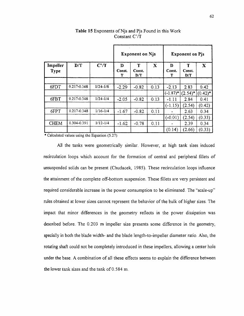
* Calculated values using the Equation (5.27)
All the tanks were geometrically similar. However, at high tank sizes induced
recirculation loops which account for the formation of central and peripheral fillets of
unsuspended solids can be present (Chudacek, 1985). These recirculation loops influence
the attainment of the complete off-bottom suspension. These fillets are very persistent and
required considerable increase in the power consumption to be eliminated. The "scale-up"
rules obtained at lower sizes cannot represent the behavior of the bulk of higher sizes. The
impact that minor differences in the geometry reflects in the power dissipation was
described before. The 0.203 m impeller size presents some difference in the geometry,
specially in both the blade width- and the blade length-to-impeller diameter ratio. Also, the
rotating shaft could not be completely introduced in these impellers, allowing a center hole
under the base. A combination of all these effects seems to explain the difference between
the lower tank sizes and the tank of 0.584 m.

63
5.7 Dual-Impeller Systems
The results obtained by Armenante et al. (1992) and Armenante and Li (1993) for multiple
radial-flow impellers system led to the conclusion that the phenomenon of solid suspension
off the tank bottom is largely dominated by the lower impeller, and that any interference in
the flow pattern generated by this impeller, such as those resulting from the presence of
more impellers, can result in higher energy requirements to achieve the same result.
The data presented in these works, for the case of two impellers, suggests that
when lowering the impeller clearance the minimum agitation speed remains constant or
slightly reduces as compared with the case of one impeller. Furthermore, the increase in
the power dissipation is lower. When the impellers are closer, at low impeller clearance,
the flow pattern of the upper impeller can be switched to that of the "single-eight", and the
detrimental effect of the interference between different flow patterns can be avoid. This
can be the case for axial-flow impellers (Oldshue, 1983).
In the present work, this observation was investigated. Three types of impellers:
6FDT, 6FBT, and 6FPT (0.0762 m) were investigated in the tank of 0.292 m. In all the
cases, impellers of the same type were used in the same shaft. The distance between
impellers was equal to the impeller diameter. For the case of the radial-flow impellers, the
lower impeller was always in the "single-eight" regime, and the upper impeller in the
"double-eight". For the 6FPTs both impellers were positioned in the "single-eight" regime.
The comparison with the single impeller was made by positioning the lower impeller at the
same impeller clearance. Figures 21, 22, and 23 show the results obtained for each dual-
impeller system, respectively.

64
For the dual-6FDT system, Figure 21(a), the minimum agitation speed and the
power consumption always increased. These observations support the detrimental effect
produced for the interference of the different flow patterns. The power consumption for
the lower impeller was always reduced, while the upper impeller consumed more power
(higher impeller clearance). For the lower impeller, the less power consumption seems to
be due to the reduction in the resistance to the movement of the impeller.
For the dual-6FBT system, Figure 22(a), the minimum agitation speed showed a
slight increase. The total power consumption was twice as compared with the single
impeller. The power consumed for each impeller was almost the same. In this case, it
seems that in the range of impeller clearance investigated, the interference of the different
flow pattern generated is not significant.
In Figure 23(a), the results obtained for the dual-6FPT system are shown. The
minimum agitation speed showed a slight decrease. The two impellers consume less power
than the single impeller. The interference between different flow patterns was avoided in
this system. However, the total power consumption was always higher. It was concluded
(see section 5.5) that all the impellers require a minimum power dissipation (as found at
C/T = 0) to overcome the resistance to the movement of the static fluid. The net effect for
the two impellers is the higher power consumption in the system.
In Figures 21(b), 22(b), and 23(b), the power number have been plotted for each
type of impeller. These figures support the conclusions obtained above. The values and
tendency observed are very similar to that obtained by Chang (1993), using a system very
similar to that used in this work.
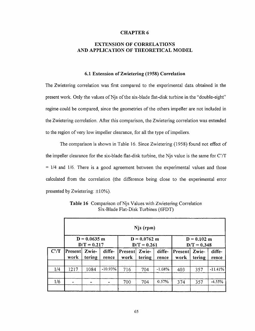
CHAPTER 6
EXTENSION OF CORRELATIONSAND APPLICATION OF THEORETICAL MODEL
6.1 Extension of Zwietering (1958) Correlation
The Zwietering correlation was first compared to the experimental data obtained in the
present work. Only the values of Njs of the six-blade flat-disk turbine in the "double-eight"
regime could be compared, since the geometries of the others impeller are not included in
the Zwietering correlation. After this comparison, the Zwietering correlation was extended
to the region of very low impeller clearance, for all the type of impellers.
The comparison is shown in Table 16. Since Zwietering (1958) found not effect of
the impeller clearance for the six-blade flat-disk turbine, the Njs value is the same for C'/T
= 1/4 and 1/6. There is a good agreement between the experimental values and those
calculated from the correlation (the difference being close to the experimental error
presented by Zwietering: ±10%).
Table 16 Comparison of Njs Values with Zwietering CorrelationSix-Blade Flat-Disk Turbines (6FDT)
D dVXVdp f (gAp/p i ) g
Nj s= a 2 exp[b 2 (C7T)1
(CIT) b3
(6.1b)
(6.1c)
66
Zwietering's correlation was extended to include the effect of the impeller
clearance, C'/T. All the experimental data were used (when necessary the relationship
between C' and C was used: C'/T = C/T + W b/2T). Three types of correlations — linear,
exponential, and power — were used:
Njs= a (C'/T) + b i (6.1a)
Dd T tru e dp f (gAp/p i ) g
Njs
D d T t rli e dp f (gAp/p i ) g
From the relation between Njs and D and T :
Njs cc Dd Ti = (D/T) d rd = (D/T)d Tt ' (6.2)
it follows that:
t = t' - d (6.3)
where both t' and d (also x) can be obtained from Table 15. Hence, it was possible to
calculate t for each of the (6.1) equations. For the case of the 6FDT, a value of 1.47 (= -
0.82 + 2.29) was obtained for t. Similarly, values of 1.25 (= -0.82 + 2.07), 0.85 (= -0.82 +
1.67), and 0.84 (= -0.78 + 1.62) for t could be obtained for the 6FBT, 6FPT, and CHEM,
respectively. These exponents were found for each type of impeller, whereas, Zwietering
correlation is for both radial-flow and axial-flow impellers. It appears that the effects of
impeller and tank diameter are different for different impeller designs (Raghava Rao et al.,
1988b).

67
For the exponent on v, dp, and (g Ap/p), the values reported by Zwietering (1958)
were assumed. These values are very similar to those reported by other authors. For the
case of the viscosity (v), a value of 0.1 is also reported by Raghava Rao et al. (1988b) and
Aravinth et al. (1996) for 6FPT and 6FBT, respectively; Chapman et al. (1983) observed
no significant effect of the viscosity for various type of impellers, and Baldi et al. (1978)
model suggests an exponent of 0.23, for eight-blade flat-disk turbine (C'/D = 1). The
value of 0.45 of the exponent on the dimensionless density (g Ltp/p) seems to be the most
accepted (Raghava Rao et al., 1988b; Myers et al., 1994b; Aravinth et al., 1996); Nienow
(1968) and Narayanan et al. (1969) reported values of 0.43 and 0.5, respectively. The
effect of the particle size (dp) on Njs seems to depend of the hydraulic regime and the
range of the particle size. A theoretical value of 0.16 for turbulent settling was reported by
Chudacek (1986). Myers et al. (1994b) found an exponent of 0.2 in the range examined
(85-19100 wn). Similar value is found in other works (Nienow, 1968; Aravinth et al.,
1996). In general, the exponents of these variables have been found to be independent of
the impeller clearance (Zwietering, 1958; Raghava Rao et al., 1988b).
For each type of correlation, the constants a's and b's and the standard deviation
were determined. As found in the preliminary correlations for Njs and Pjs in the section
5.1, the power law form was very poor in all cases. The exponential form was slightly
superior to the linear form. In Table 17, the final correlations are shown. The agreement
between the experimental values and the correlations presented are good, the maximum
deviation being of ±5.44%, ±2.72%, ±3.43%, and ±2.87%, for the 6FDT, 6FBT, 6FPT,
and CHEM, respectively. Graphical comparison are shown in Figure 24(a, b, c, d).

68
Table 17 Extension of Zwietering Correlation
For flat-bottom tank, fully baffled + :
Six-Blade Flat-Disk Turbine:
0.91 v" dp0.2 (gAp/p1)0.45 T1.47 x0.13 exp ( 2.15 C'/T )Njs' - (6.4)
D2.29
T = 0.188-0.584 m, D = 0.0635-0.203 m, C'/T < 0.16Glass beads, dp = 110 p.m, p, = 2,500 Kg/m 3 , X = 0.5-1.5 wt/w0/0, Tap water at 22 °C
Six-Blade Flat-Blade Turbine:
1.40 v" dp°'2 (gApip00.45 T1.25 -0.13 exp ( 1.96 C'/T )Njs' - (6.5)
D2.07
T = 0.188-0.584 m, D = 0.0635-0.203 m, C'/T < 0.21Glass beads, dp = 110 p.m, p s = 2,500 Kg/m3 , X = 0.5-1.5 wt/wt%, Tap water at 22 °C
Six-Blade Flat (45°) Pitched-Blade Turbine:
2.33 v" dpo.2 (gApio0.45 T0.87 -.o.11 exp ( 0.65 C'/T )Njs' - (6.6)
D1.67
T = 0.188-0.584 m, D = 0.0635-0.203 m, C'/T < 0.26Glass beads, dp = 110 p,m, p, = 2,500 Kg/m 3 , X = 0.5-1.5 wt/wt%, Tap water at 22 °C
Chemineer HE-3 Impeller:
3.72 v0•1 dp0.2 (gApipi)0. 45 T0.84 .‘ A .11 exp ( 0.72 C'/T )Njs' - (6.7)
D 1.62
T = 0.292-0.584 m, D = 0.102-0.229 m, C'/T < 0.25Glass beads, dp = 110 p, = 2,500 Kg/m3 , X = 0.5-1.5 wt/wt%, Tap water at 22 °C
Njs' in rps
69
6.2 Application of Baldi et al (1978) Theoretical Model
The theoretical model developed by Baldi et al. (1978) was also applied to the
experimental values obtained in this work. The experimental approach was similar and the
expression given in Equation (3.5) was used:
Z cc Rem'
A log-log plot (Z against 1/Rem), for C'/D ratios of 1/2, 1/4, and 1/5, are shown in Figure
25(a, b, c, d), for each type of impellers. In each case (C'/D ratio and impeller type), the Z
values were found to be independent of D/T (Baldi et aL, 1978; Chapman et al., 1983).
For the case of the 6FDT, Figure 25(a), at C'/D = 1/2, the 0.102 m impeller size
was found in the regime of the "double-eight". When this value is discarded, the

70
Z = 1.83±0.02 (C'/D = 1/2) (6.14)
Z oc Rem"4 (C'/D = 1/4) (6.15)
Z ac Rem"° (C/D = 1/5) (6.16)
For this case the Z values depend only slightly of the Rem.
For the case of the CHEM, for all the values of C/D, Z was found to be
independent of the Rem:
Z = 2.36±0.06 (C'/D = 1/2) (6.17)
Z = 2.45±0.04 (C'/D = 1/4) (6.18)
Z = 2.43±0.06 (C'/D = 1/5) (6.19)
For this case, the Z values do not depend of the Rem.
The exponents found for each type of impellers are very close, independent of the
C'/D ratio. A statistical analysis shows that there is no need to complicate the Equation
(3.5) by considering individual C'/D ratios. In this case, the following relationships
between the Z values and the Rem can be found:
Z cc Rem"6±°.06 (6FDT) (6.20)
2 oc Rem0.24±0.06 (6FBT) (6.21)
Z = 1.84±0.03 (6FPT) (6.22)
Z = 2.41±0.06 (CHEM) (6.23)
These results show the insensitivity of the exponents on the different variables to
variations of the impeller clearance as revealed by several authors (Zwietering, 1958;
Nienow, 1968; Chapman et al., 1983; Raghava Rao et al., 1988b).
71
Although, only one tank size (0.292 m) and one solids loading (0.5 wt/wt%) were
used, the results obtained in this work appear to be in disagreement with the experimental
observations of Baldi et al. (1978) and Chapman et al. (1983). Baldi et al. (1978) found
for eight-blade flat-disk turbines, that the dimensionless group Z (or the local dissipated
power to average dissipated power) was not affected by the hydrodynamic conditions very
near to the tank bottom (as low as C'/D = 0.5). Chapman et al. (1983) confirmed this
experimental result at C'/D = 0.5 for 6FDT, and found that the Baldi et aL model was not
successful for other geometries. The inadequacy of this model can be attributed to the
complex flow, which cannot be described by a simple equation (Nienow, 1985). In this
work, for the 6FDT in the 0.292 m tank, at C'/D = 0.5 ratio, the 0.102 m impeller size
was found in the "double-eight" regime. For the other sizes, a value of 1.22±0.05 for Z
can be found (1.18±0.08 for the three sizes) apparently in agreement with Baldi et al (2
for eight-blade flat-disk turbine) and Chapman et al. (1.17±0.15 for 6FDT). However, at
lower C'/D ratios (1/4 and 1/5), the effect of the hydrodynamic conditions is significant. It
must be noticed that the description of the solids suspension given by Baldi et al (1978) in
their work corresponds to the "double-eight" regime, and the experimental observation of
Chapman et al. (1983) was conducted using a value of C'/T = 1/4, corresponding also this
value to the "double-eight" regime. Unlike these studies, in this work, the application of
the model was performed in the "single-eight" regime, with the impeller very near to the
tank bottom. Although this represents the best attempt at a theoretical analysis of the
solids suspension, there are certain doubts on the application of the Baldi et al. model very
near to the tank bottom (Witcherle, 1988).
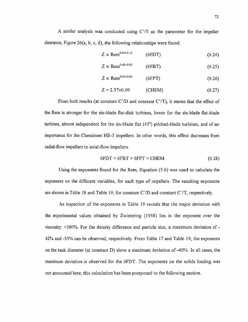
72
A similar analysis was conducted using C'/T as the parameter for the impeller
clearance, Figure 26(a, b, c, d), the following relationships were found:
Z cc Remo.91±0.15 (6FDT) (6.24)
Z cc Rem0.4o+0.03 (6FBT) (6.25)
Z cc Remo.o5±0.01 (6FPT) (6.26)
Z = 2.3 7±0. 09 (CHEM) (6.27)
From both results (at constant C'/D and constant C'/T), it seems that the effect of
the Rem is stronger for the six-blade flat-disk turbines, lower for the six-blade flat-blade
turbines, almost independent for the six-blade flat (45°) pitched-blade turbines, and of no
importance for the Chemineer HE-3 impellers. In other words, this effect decreases from
radial-flow impellers to axial-flow impellers:
6FDT > 6FBT > 6FPT > CHEM (6.28)
Using the exponents found for the Rem, Equation (3.6) was used to calculate the
exponents on the different variables, for each type of impellers. The resulting exponents
are shown in Table 18 and Table 19, for constant C'/D and constant C'/T, respectively.
An inspection of the exponents in Table 19 reveals that the major deviation with
the experimental values obtained by Zwietering (1958) lies in the exponent over the
viscosity: +380%. For the density difference and particle size, a maximum deviation of -
42% and -55% can be observed, respectively. From Table 17 and Table 19, the exponents
on the tank diameter (at constant D) show a maximum deviation of -40%. In all cases, the
maximum deviation is observed for the 6FDT. The exponents on the solids loading was
not accounted here, this calculation has been postponed to the following section.
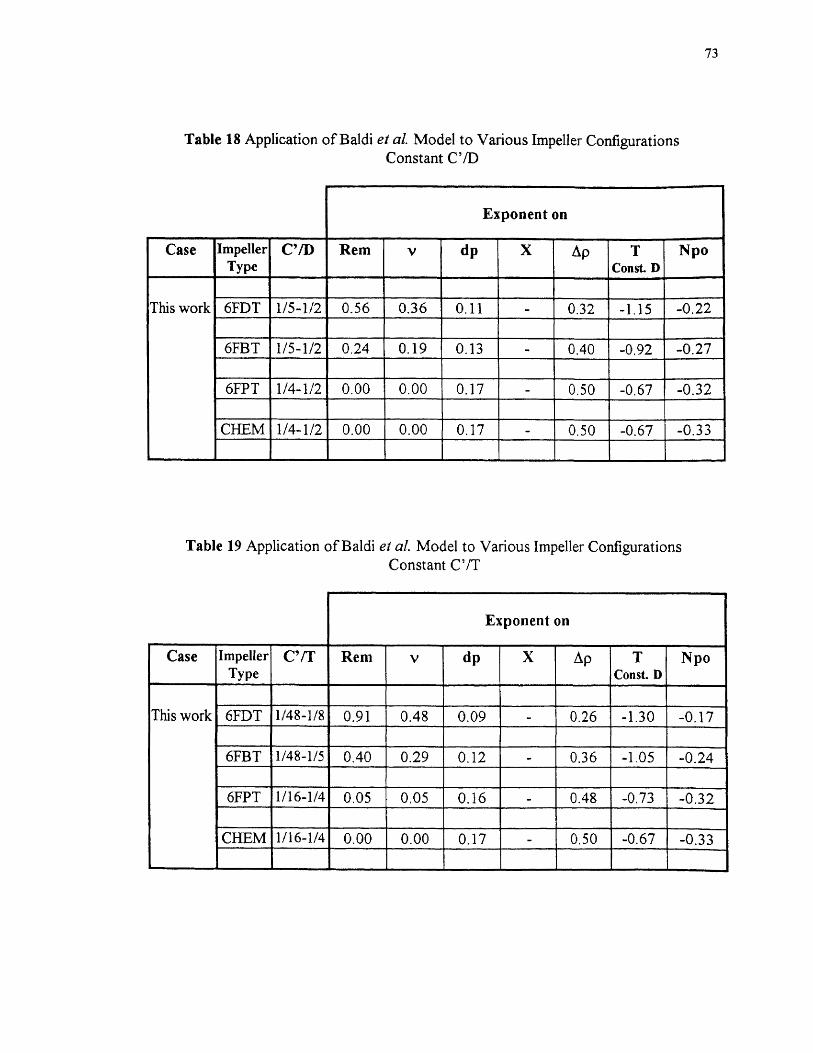
73

74
6.3 Extension of Baldi et al. (1978) Theoretical Model
The theoretical model of Baldi et aL (1978) was extended to include the impeller
clearance and solids loading effects. The experimental results were interpreted on the basis
of the dimensionless numbers Z, Rem, C'/T, and X:
Z = f (Rem, C'/T, X) (6.29)
Following the experimental approach of Baldi et al. (1978), Conti et al. (1981)
interpreted their results using the dimensionless numbers Z, Rem, Npo, C'/D, T/D, and X,
for eight-blade flat-disk turbine. Since Z was found to be independent of T/D, they used an
expression similar to Equation (6.29). When the Conti et al. correlation, Equation (3.13),
is used to calculate Njs for the 6FDT, the values are always higher than the experimental
Njs, Table 20. This correlation was deduced for eight-blade flat-disk turbines. Since Njs
increases with a decrease of the number of blades (Chapman et al., 1983), and also with a
decrease in the power number (deduced from the correlation), the agreement improves.
Table 20 Comparison of Njs Values with Conti et aL CorrelationSix-Blade Flat-Disk Turbine (6FDT)

75
From the observation of the experimental results, the following expression
between Z an X can be obtained:
Z oc (6.30)
This is in agreement with the experimental results obtained by Baldi et al. (1978) and
Conti et al. (1981). When this expression is combined with the Equation (3.5), the
following expression can be obtained:
Z = Rmn f(C/T) (6.31)
Similarly to the extension of the Zwietering correlation, three types of correlations
were tested for the effect of C'/T — linear, exponential, and power. Previously, the
correlation was conducted using only the experimental values of Njs and Npo obtained for
the tank of 0.292 m. When the values obtained for the tanks of 0.188 m, 0.244 m, and
0.584 m were included, the agreement found was always poor. This suggests a
disadvantage of these correlations when scaling-up. Conti et al. correlation was conducted
using only one tank size (0.19 m). The values for T = 0.584 m were discarded since the
Npo obtained in this tank were unusual high for the 6FDT, 6FBT, and 6FPT. For the same
reason the 0.0635 m 6FPT was not considered in the correlations. Since Njs oc 1 4, at
constant D, and based on the observation given above, the following scale-up rule was
used:
Njs/T oc T I-1 (6.32)
From Section 6.1 the exponents (t-1) can be obtained: 0.47 (= 1.47 - 1), 0.25 (= 1.25 - 1),
and -0.15 (= 0.85 - 1) for the 6FDT, 6FBT, and 6FPT, respectively. Hence, Z and Rem
can be corrected in the following way:

76
Z* = Z ( T/0.292 ) 14 (6.33)
Rem* Rem (T/0,292) #-1 (6,34)
Among the correlations tested, the exponential form gave the best results. The
effect of C'/T on both Njs and Npo are included in the exponential form. The correlations
obtained are shown in Table 21. For the CHEM, according to the observation given
before, two separated set of correlations for each tank size are shown.
The results obtained support the conclusions drawn before. When the impeller is
very near to the tank bottom, the hydrodynamic conditions affect more to the radial-flow
impellers than the mixed axial- and axial-flow impellers.
From the correlations in Table 21, expressions for Njs can be deduced using
Equation (3.6), These correlations are shown in Table 22, for 6FDT, 6FBT, and 6FPT,
and in Table 23 for CHEM. Experimental Njs values have been plotted against calculated
Njs values in Figure 27(a, b, c, d). The agreement between the experimental Njs and the
correlations are good, the maximum deviation being of ±5.20%, ±4.81%, ±2.02%, and
±2.81% for the 6FDT, 6FBT, 6FPT, and CHEM, respectively. Similarly to Section 6.2,
Table 22 and Table 23 show a big discrepancy in the exponent on the viscosity: +360%.,
when compared to the Zwietering correlation The maximum deviation for the density
difference, particle size, and tank diameter (constant D) are -40%, -56%, and -40%
respectively. Again, these maximum deviations occur for the 6FDT. The exponents on the
solids loading show a good agreement with the experimental values obtained in this work
(maximum deviation = ±15%). The effect of the impeller clearance are very similar to that
found in the extension of the Zwietering correlation.
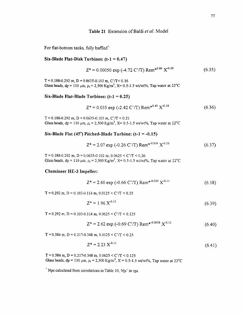
77
Table 21 Extension of Baldi et al. Model
For flat-bottom tanks, fully baffled+ :
Six-Blade Flat-Disk Turbines: (t-1 = 0.47)
Z* = 0.00050 exp (-4.72 C'/T) Rem* 086 r128(6.35)
T = 0.188-0.292 m, D = 0.0635-0.103 m, C'/T< 0.16Glass beads, dp = 110 pin, p s = 2,500 Kg,/m 3 , X= 0.5-1.5 wt/wt%, Tap water at 22 °C
Six-Blade Flat-Blade Turbines: (t-1 = 0.25)
Z* = 0.035 exp (-2.42 C'/T) Rem*" x-0,18 (6.36)
T = 0.188-0.292 m, D = 0.0635-0.103 m, C'/T < 0.21Glass beads, dp = 110 pm. ps = 2,500 Kg/m3 , X= 0.5-1.5 wtlwt%, Tap water at 22 °C
Six-Blade Flat (45 °) Pitched-Blade Turbine: (t-1 = -0.15)
Z* = 2.07 exp (-0.26 C'/T) Rem*-0,016 x-0.10 (6.37)
T = 0.188-0.292 m, D = 0.0635-0.102 m, 0.0625 < C'/T < 0.26Glass beads, dp = 110 p.m. p s = 2,500 Kg/m 3 , X= 0.5-1.5 wtlwt%, Tap water at 22 °C
Chemineer HE-3 Impeller:
Z* = 2.60 exp (-0.66 C'/T) Rem *-0.020 yO.11 (6.38)
T = 0.292 m, D = 0.103-0.114 0.0125 < C'/T < 0.25
Z * = 1.96 X j3A1 (6.39)
T = 0.292 m, D = 0.103-0.114 m, 0.0625 < C'/T < 0.125
Z * = 2.62 exp (-0.69 C'/T) Rem*4"°58 x-0.11 (6.40)
T= 0.584 m, D 0.217-0.348 m, 0.0125 < C'/T < 0.25
Z * = 2.23 X -"' (6.41)
T = 0.584 m, D = 0.217-0.348 m, 0.0625 < C'/T < 0.125Glass beads, dp = 110 wn, p s = 2,500 Kg,/m3, X = 0.5-1.5 wt/wt%, Tap water at 22 °C
Npo calculated from correlations in Table 10, Njs' in rps
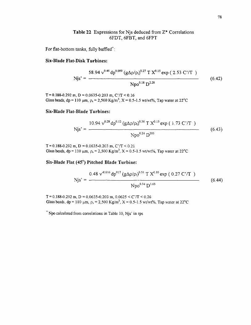
78
Table 22 Expressions for Njs deduced from Z* Correlations6FDT, 6FBT, and 6FPT
For flat-bottom tanks, fully baffled+ :
Six-Blade Flat-Disk Turbines:
58.94 v0.46 dp0.089 (gAp/p00.27 T .x0.15 exp ( 2.53 C'/T )Njs' — (6.42)
Npo°'18 D2.28
T = 0.188-0.292 m, ID = 0.0635-0.203 m, C'TT < 0.16Glass beads, dp = 110 p.m, p, = 2,500 Kg/m 3, X = 0.5-1.5 w-t/w-t%, Tap water at 22°C
Six-Blade Flat-Blade Turbines:
10.94 v0'28 dp0.12 (gApipoo.36 T x0.13 exp ( 1,73 C'/T )Njs' — (6.43)
Npoo.24 D205
T = 0.188-0.292 m, D = 0.0635-0.203 in, CR' < 0.21Glass beads, dp = 110 1.1m, ps = 2,500 Kg/m3 , X = 0.5-1.5 wt/ t%, Tap water at 22 °C
Six-Blade Flat (45°) Pitched Blade Turbine:
0.48 v"" 16 dp°17 (gAp/p1)" 1 T X°3° exp ( 0.27 C'/T )Njs' — (6.44)
Npo0.34 D 1.65
T = 0.188-0.292 m, D = 0.0635-0.203 m, 0.0625 < C'/T < 0.26Glass beads, dp = 110 1..cm, p s = 2,500 Kg/m3 , X = 0.5-1.5 wth.v0/0, Tap water at 22 °C
Npo calculated from correlations in Table 10, Njs' in rps

79
Table 23 Expressions for Njs deduced from Z* CorrelationsCHEM
For flat-bottom tanks, fully baffled + :
Chemineer HE-3 Impeller:
0.38 V0'02 dpo.17 (gApip1)0.51 T xr0.12 exp ( 0.68 C'/T )Njs' = (6.45)
Npo0.34 D 1.64
T = 0.292 m, D = 0.103-0.114 m, 0.125 < C'/T < 0.25
0.51 dp°•17 (gApip00.50 T x011
Njs' — (6.46)Npo°33 D 1.67
T = 0.292 m, D = 0.103-0.114 m, 0.0625 < C'/T < 0.125
0.38 v-0.006 dp0.17 (gdp/p1)0.5o T xo.n exp ( 0.69 C'/T )Njs' — (6.47)
Np00.34 D1.66
T = 0.584 m, D = 0.217-0.348 m, 0.125 < < 0.25
0.45 dp°'17 (gAp/p00.50 T x0.11
Njs' — (6.48)Npo°33 D1.67
T = 0.584 m, D = 0.217-0.348 m, 0.0625 < C'/T < 0.125Glass beads, dp = 110 1.tm, p, = 2,500 Kg/m 3 , X = 0.5-1.5 wt/wt%, Tap water at 22 °C
Npo calculated from correlations in Table 10, Njs' in rps
CHAPTER 7
CONCLUSIONS
- Mixed axial-flow and axial-flow impellers are more efficient than the radial-flow
impellers for complete off-bottom suspension, when the impeller is positioned close to
the tank bottom. However, in the range in which the throttling effect is significant, the
efficiency of the mixed axial-flow and axial-flow impellers decreases.
- The exponents for the impeller diameter, tank diameter, and solids loading in the Njs
equations are very similar to those reported in the literature, in particular, to those
presented by Zwietering (1958). The impeller off-bottom clearance does not appear to
affect these values.
- During scale-up, the effects of minor dimensions and minor differences in geometry are
significant for power consumption. These effects are not significant for scaling-up the
minimum agitation speed, for complete off-bottom suspension.
- Although, some improvement in the minimum agitation speed has been noticed, the
presence of a second impeller — with the lower impeller positioned very near to the
tank bottom — increases the total power consumption. This increase in the power
consumption does not justify the use of two impellers for the task of complete off-
bottom suspension.
- The extension of the Zwietering's correlation allows a prediction of the effect of the
impeller clearance very near to the tank bottom. This effect was included in a
modification of the Zwietering's equation using an exponential term.
80
81
The application of the Baldi et al. (1978) model, when the impeller is placed very close
to the tank bottom, reveals that the effect of the hydrodynamic conditions is more
significant for the radial-flow impellers than the mixed axial-flow and axial-flow
impellers. The results obtained here are in disagreement with the experimental
observations of Baldi et al. (1978) and Chapman et al. (1983). However, in their studies
the application of the model was conducted in the "double-eight" regime, while in this
work the model was applied to the "single-eight" regime. The extension of the model to
include the effect of the impeller clearance was successful; although, corrections for the
dimensionless group, Z, and the modified Reynolds number were required for scaling-
up. The expressions for Njs deduced after this extension show a big discrepancy in the
effect of the viscosity when compared to the Zwietering's correlation.
APPENDIX A
FIGURES FOR CHAPTER 5 AND 6
This appendix includes the figures described in Chapter 5 (Results and Discussion) and
Chapter 6 (Extension of Correlations and Application of Theoretical Model). For the
effect of the impeller clearance, these figures include:
Effect on Njs, Pjs, and Npo (Figure 5-Figure 7)
Npo correlation (Figure 8)
Comparison at constant D/T (Figure 9-Figure 11)
For the effects of impeller diameter, tank diameter, and solids loading, these figures
include:
Effects of D, T, and X on Njs (Figure 12-Figure 17)
Effects of D, T, and X on Pjs (Figure 18-Figure 20)
For dual-impeller systems, these figures include:
Dual-6FDT System (Figure 21)
Dual-6FBT system (Figure 22)
Dual-6FPT system (Figure 23)
For the extension of correlations and application of theoretical model, these figures
include:
Extension of Zwietering Correlation (Figure 24)
Effect of Rem on Z Values (Figure 25-Figure 26)
Extension of Baldi et al. model (Figure 27)
82

1600
1400
1200
1000
800
600
400
200
0
1600
1400
1200
1000
800
600
400
200
0
Njs (rprn)
83
1/48 1/24 1/16 1/12
1/8 1/6
1/4
C/TT-0.292 m, X-0.5 wt/wt%
Figure 5(a) Effect of C/T on Njs(6FDT)
Njs (rpm)
1/48 1/24 1/16 1/12
1/8 1/6
1/5
1/4
C/TT-0.292 m. X-0.5 wt/wt%
Figure 5(b) Effect of C/T on Njs(6FBT)
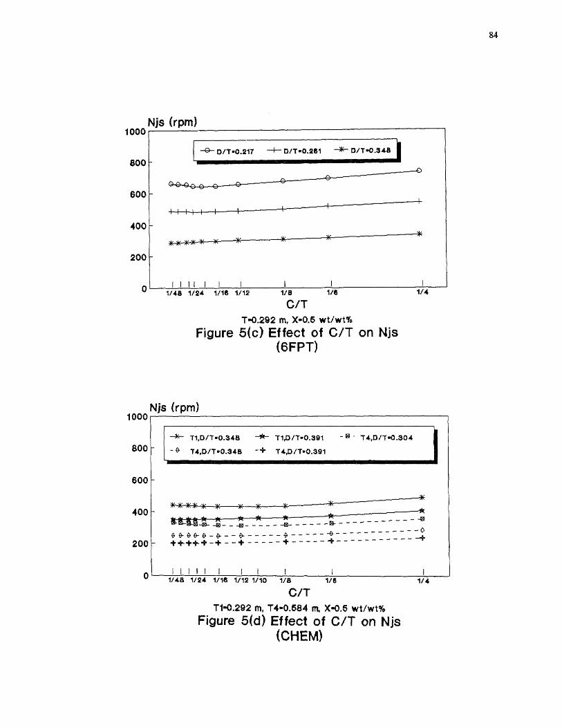
84
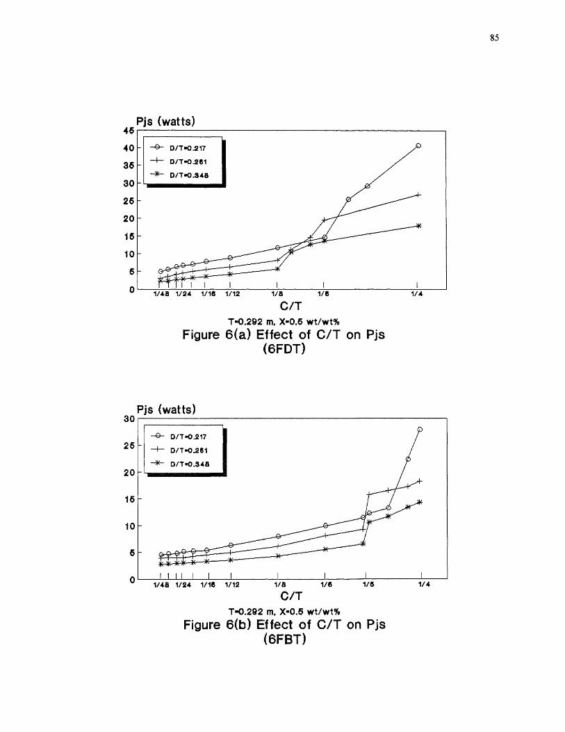
85
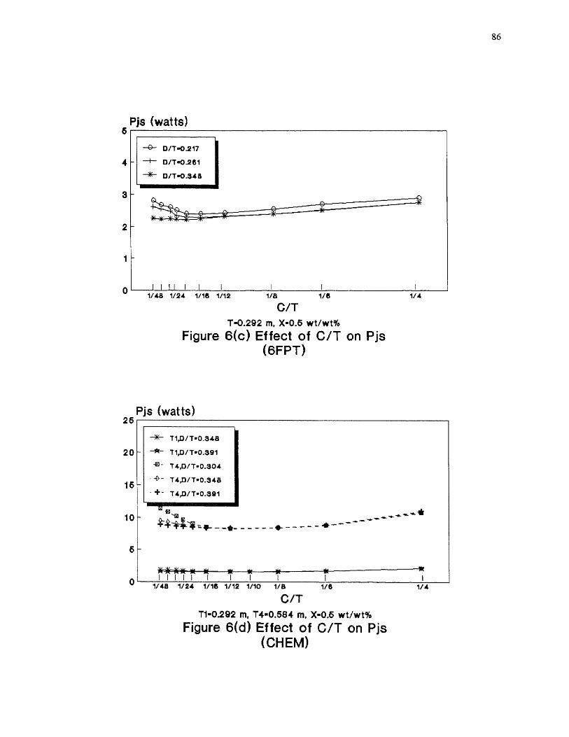
86
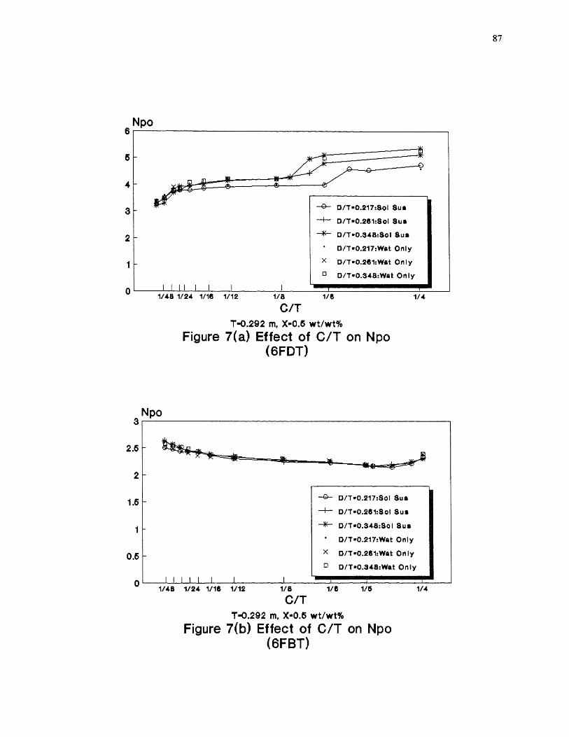
87
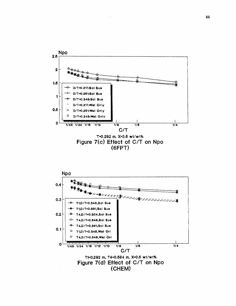
88
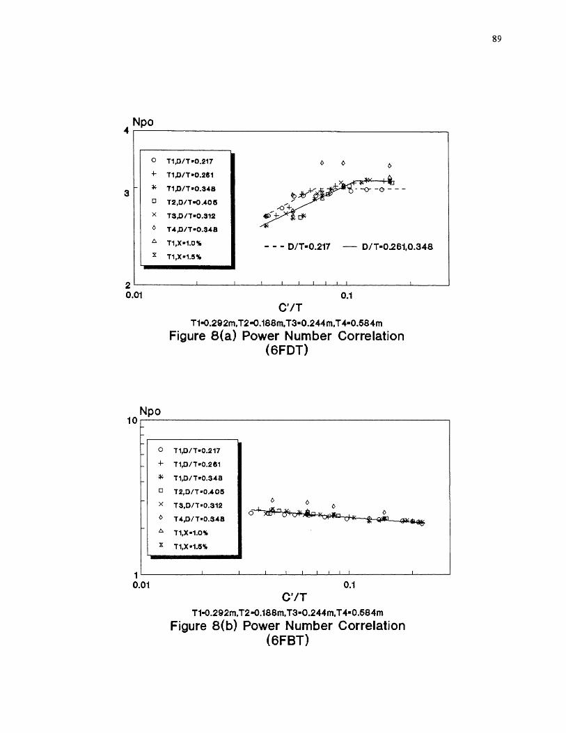
89
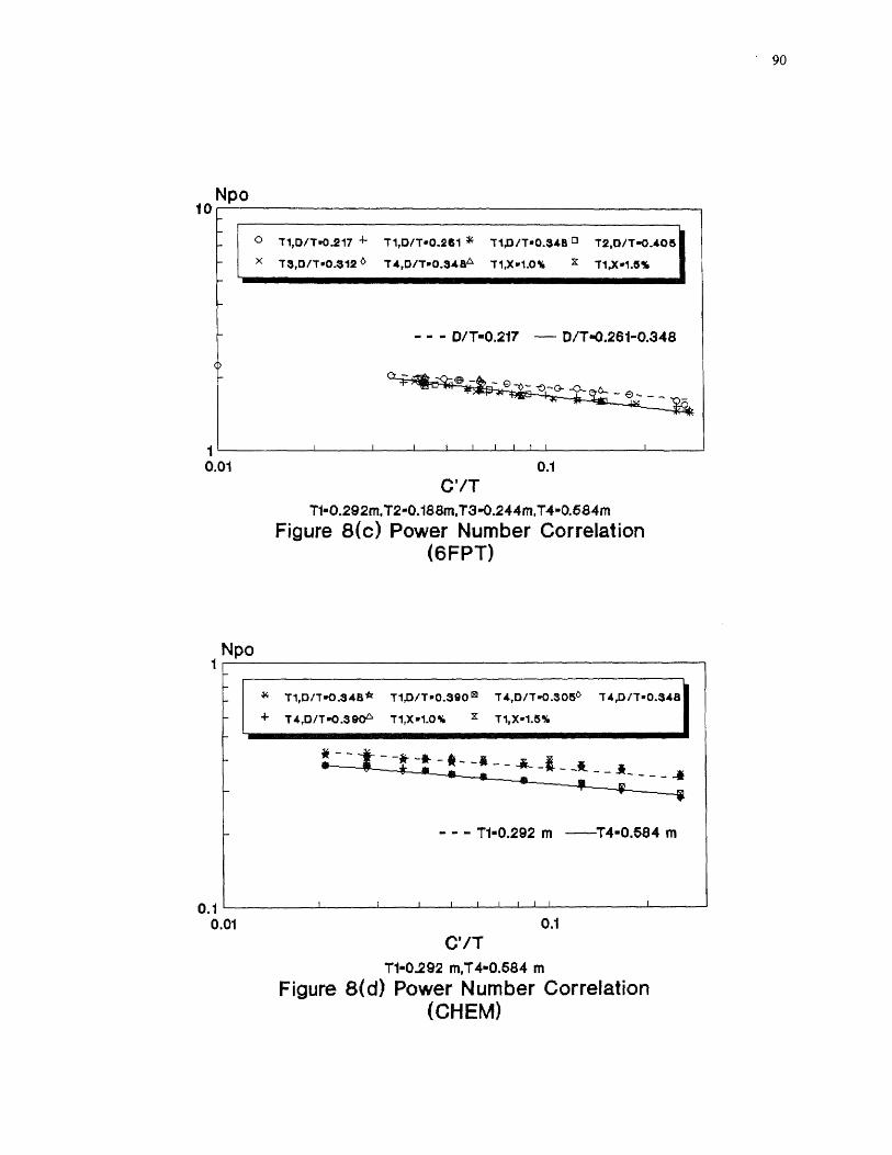
90

1/5 1/5 1/4 115 1/41/441 1/24 Vie 1/12 1/10 1/45 1/24 1115 1112 1110 1/5 1/5
-z- eFDT -*-- SFBT SFPT -+- CHEM
1-111-rt--1-1—t
C/T
C/TT.O202 frit X•0.5 wt/wt%
T-0292 m, Xe0.6wvvits
Figure 9(a) Comparison at D/T=0.348
Figure 9(b) Comparison at D/T-0.348(Njs)
(Pjs)
Npo
1/45 1/24 1/1111 1/12 1/10 1/11 1/5 1/4
C/TT.0292 rn, x-o.a wt/wt%
Figure 9(c) Comparison at D/T=0.348(Npo)
Comparison for D=0.102 m,T=0.292 m, X=0.5 wt/wt%
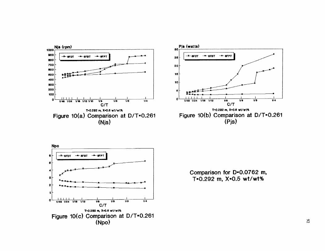
i000 NJ* (rpm)
900800
TOO
000
500
400
300
200
100
0 1/48 1124 Vie 1(12 1/10 1/8 115
C/TT■0292 m, X•0.5 wt/wt%
Figure 10(a) Comparison at D/T=0.261(Njs)
1/5 1/4 1/48 1/24 1/1e 1/12
1/8 1/5
1/5
1/4
C/TT•0292 m, x-ea wt/wt%
Figure 10(b) Comparison at D/T=0.261(Pjs)
Npo
eFDT 8F13T SFPT
I I I I I I 1/48 1/24 Me 1/12
VS 1/5
1/5
1/4
C/TT-0292 ni, X-0.5 wt/wt%
Figure 10(c) Comparison at D/T=0.261
a
a
4
a
2
10
Comparison for D-0.0762 m,T=0.292 m, X=0.5 wt/wt%
(Npo)
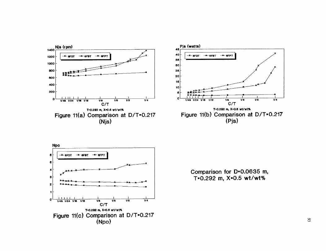
V41 1/24 1/16 1/12
VS 1/6
1/5
1/4
C/TT-0.292 m, X-0,6 Whitt%
Figure 11(a) Comparison at D/T=0.217(Njs)
1/41 1/24 1/16 1/12
VS 1/6
1/5
1/4
C/TT-0292 m, X-0.5 wt/wt%
Figure 11(b) Comparison at D/T-0.217(Pjs)
Npo
--x- eFDT SFBT --a- OFPT
Comparison for D=0.0635 m,T-0.292 m, X-0.5 wt/wt%
1 1 1 1 1 1 1 1 1 1 1 1/48 1/24 1116 1/12
1/1
VS
1/4
C/TT-0292 m, X-0.5 wt/wt%
Figure 11(c) Comparison at D/T-0.217(Npo)

94

95
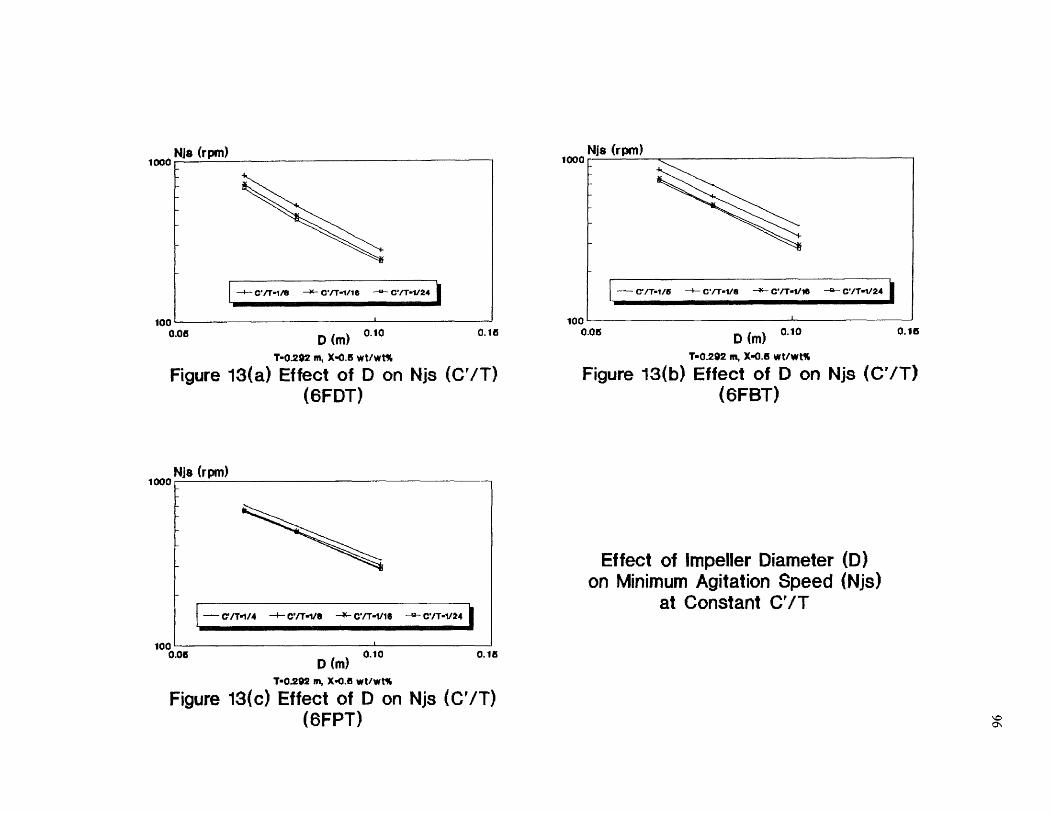
0.06 D (m) 0.10
0.16
T-0202 in, X-0.6 wt/wt%
Figure 13(a) Effect of D on Njs (Grin(6FDT)
0.15100
0.06 D (m) 0.10
T-0.292 ris, X-0.6 wt/wt%
Figure 13(b) Effect of D on Njs (C'/T)
Effect of Impeller Diameter (D)on Minimum Agitation Speed (Njs)
at Constant C'/T
(6FBT)
1000
T-0.292 in, x.o.es wt/wt%
Figure 13(c) Effect of D on Njs (C'/T)(6FPT) cr.
Nis (rpm)i000 Nis (rpm)
100
-1- C7T•1/8 -14- C'/T-1/16 -.-- C/T•1/24
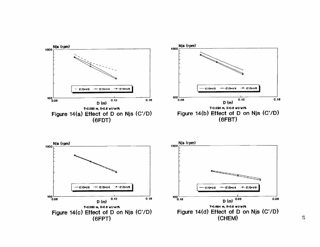
1000.06 0.10
D (r11)
T-0292 m, X-0.5 wt/wt%
Figure 14(a) Effect of D on Njs (C'/D)(6FDT)
D (m) 0.10
0.16
T-0.292 nt,
Figure 14(b) Effect of D on Njs (C'/D)(6FBT)
0.15
T-0.292 in, X-0.5 wt/wt% T-0.554 rts, X-0.5 wt/wt%
Figure 14(c) Effect of D on Njs (C'/D) Figure 14(d) Effect of D on Njs (CM)(6FPT) (CHEM)
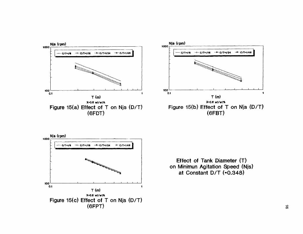
0.1
T (m)X-0.6 wt/wt%
Figure 15(a) Effect of T on Njs (D/T)(6FDT)
0.1T (m)
X-0.6 wt/wt%
Figure 15(b) Effect of T on Njs (D/T)(6FBT )
Effect of Tank Diameter (T)on Minimun Agitation Speed (Njs)
at Constant D/T (-0.348)
1000 Njs (rpm)
- C/T.1/19 -4- CIT.1/14 -44" C/T=1/24 -0- C/T-1148
100 0.1 1
T (m)X-0.6 wt/wt%
Figure 15(c) Effect of T on Njs (D/T)(6FPT)
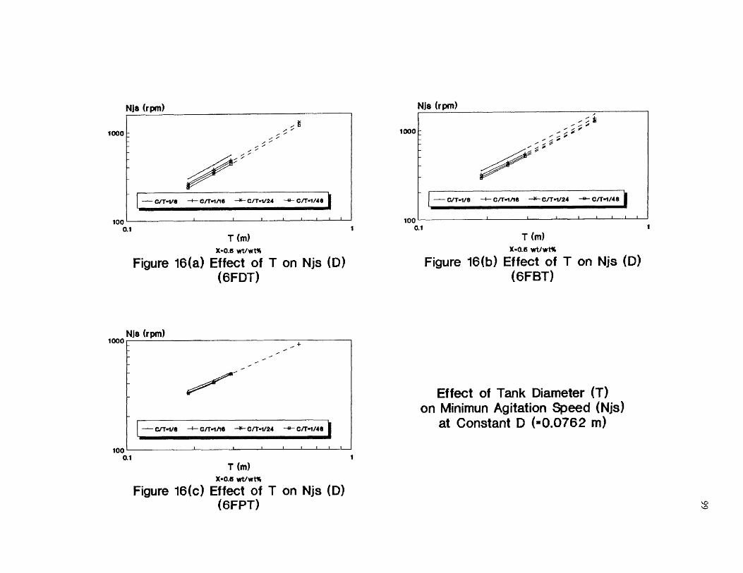
100100
1000 1000
Nis (rpm) Nis (rpm)
0.1 1
0.1T (m)
X0.6 wt/Wt%
Figure 16(a) Effect of T on Njs (D)(6FDT)
0.1T (m)
x.0.15 wt/wt%
Figure 16(b) Effect of T on Njs (D)(6FBT)
Effect of Tank Diameter (T)on Minimun Agitation Speed (Njs)
at Constant D (-0.0762 m)
T (m)x•o.a wt/wt%
Figure 16(c) Effect of T on Njs (D)(6FPT)
Nis (rpm)loco
100
4-
— Grrw1/11 —I-- Oft■Itie — C it w1/24 —0— C/T-1/41
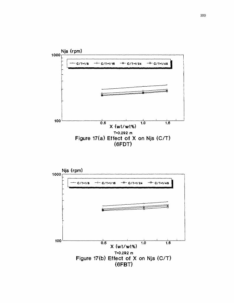
1.60.6 1.0X (wt/wt%)
T-0.292 mFigure 17(a) Effect of X on Njs (C/T)
(6FDT)
1.60.5 1.0X (Wt/Wt%)
T-0.292 mFigure 17(b) Effect of X on Njs (C/T)
(6FBT)
Njs (rpm)
Njs (rpm)
1000
100
1000
100
100
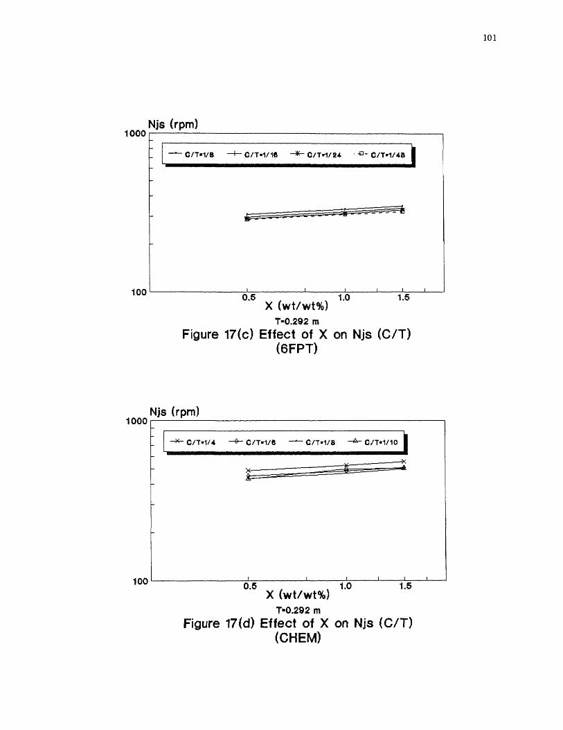
101

102

Pis (watts)too
CVT-1/7- C'/T1/12
1 0
-
C'/T-itle
- C'/T1/24
1
0.10.1
T (m)X-0.5 wtivit%
10
- V/T.1/12cifrone
- VIT•1/24
1
0.10.1 1
Pis (watts)too
0.1
1
T (m)X-0.5 wtivrt%
Figure 19(a) Effect of T on Pjs (D/T)(6FDT)
Figure 19(b) Effect of T on Pjs WIT)(6FBT)
T (m)X-0.6 wvwts
Figure 19(c) Effect of T on Pjs (D/T)(6FPT)
Effect of Tank Diameter (I)on Power Dissipation (Pjs)at Constant DIT (.0.348)

104
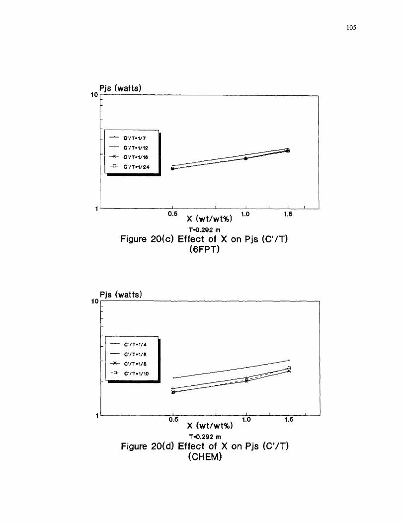
105

106
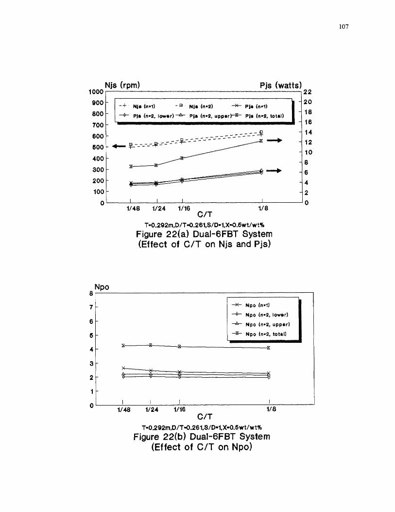
107
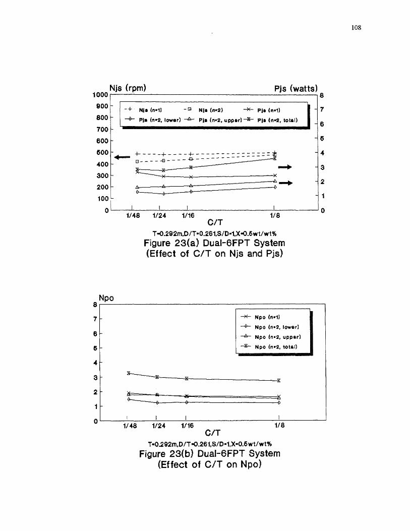
108
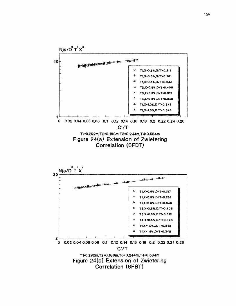
109

110

)
V/0.4/2 + C/D-1/4 4r C 71).1/6
x
4
1/RemilE05 8 1 0
T-0.202 in, X-0.8 wt/wt%
Figure 25(a) Effect of Rem on Z Valuesfor Various C'/D Ratios (6FDT)
4
a
101/Rern•E05
T-0202 m, X-0.8 wtlwt%
Figure 25(b) Effect of Rem on Z Valuesfor Various C'/D Ratios (6FBT)
2
Z values
C7C0.112 /D-i/ 4 CVD.1/15
4 8 101/Rem.E05
T-0.202 rn, X-0.6 wt/wt%
Figure 25(c) Effect of Rem on Z Valuesfor Various C'/D Ratios (6FPT)
3 Z values
2
1/Rem.E06T-0.884 tn, X-0.6 wtArt%
Figure 25(d) Effect of Rem on Z Valuesfor Various C'/D Ratios (CHEM)

Z values
Z values
104 1/Rem-1E06
1 0
T.0292 X-0. wt/wt%
Figure 26(a) Effect of Rem on Z Valuesfor Various C'/T Ratios (6FDT)
1/Rem.1E061.0292 m, X-0.5 wtiwt%
Figure 26(b) Effect of Rem on Z Valuesfor Various C7T Ratios (6FBT)
Z values3
2
0/1.1/4 -4-- 071.1/8 C./T.1/13 -0- C'/T-1/24
4
8
1 0 2
1/Rm. -1E06
1/Rem-1E061.0292 m, X.0.5 wt/wt%
X.0.8 wt/wt%
Figure 26(c) Effect of R on Z Values
Figure 26(d) Effect of R on Z Valuesfor Various C'/T Ratios (6FPT)
for Various C'/T Ratios (CHEM)

1200O 200 400 600 800 1000
Njs calculated (rpm)T1-0.292 m, T2-0.188 m, T3-0.244 m
Figure 27(b) Extension of Baldi et al.Model (6FBT)
Njs experimental (rpm)
1
T1,13/7.0.217-0.348
4- T2,13/7•0.405
44 T3,D17.0.312
o T1,0/7.0.3413,ALL X
-1111■1111111111111119111111111111111■111111111•11111111111111111■
O 200 400 600 800
Njs calculated (rpm)T1-0.292 m, T2-0.188 m, T3-0.244 m
Figure 27(a) Extension of Baldi et al.Model (6FDT)
Njs experimental (rpm)
113
12001000
1200
1000
800
600
400
200
0
1200
1000
800
600
400
200
0
T1,D/T•0-217-0.3413
- 72,13/T■0.405
;lc 13,1117■0.312
❑ T1 rD/T.0.3411,ALL X

500 6000 100 200 300 400
Njs calculated (rpm)T1-0.292 m, T2-0.188 m,T3-0.244 m
Figure 27(c) Extension of Baldi et al.Model (6FPT)
6005000 100 200 300 400
Njs calculated (rpm)T1-0.292 m, T4-0.684 m
Figure 27(d) Extension of Baldi et al.Model (CHEM)
Njs experimental (rpm)
Njs experimental (rpm)
114
600
600
400
300
200
100
0
600
500
400
300
200
100
0
71,D/1.0.2151-0.348
4- T2,13/7.0.405
T3,D/T.0.312
0 T1,13/7.0.3413,ALL X
-11111111111111111111111111111,111•1111111111111111111111111=11
One correlation for each tank size
T1,13/7•0.348-0.391
4- T4P/T.0.305-0.391
T1,D/T.'0.348,ALL X
APPENDIX B
EXPERIMENTAL DATA
This appendix tabulates the experimental data obtained in this work. The experimental
data for the effects of the impeller clearance on Njs, Pjs, and Npo include:
6FDT (Table 24-Table 26)
6FBT (Table 27-Table 29)
6FPT (Table 30-Table 31)
CHEM (Table 32-Table 34)
The experimental data for the effects of T and X include:
Effect of T (Table 35-Table 42)
Effect of X (Table 43-Table 46)
The experimental data for the dual-impeller systems include:
Dual-6FDT System (Table 47)
Dual-6FBT System (Table 47)
Dual-6FPT System (Table 47)
115
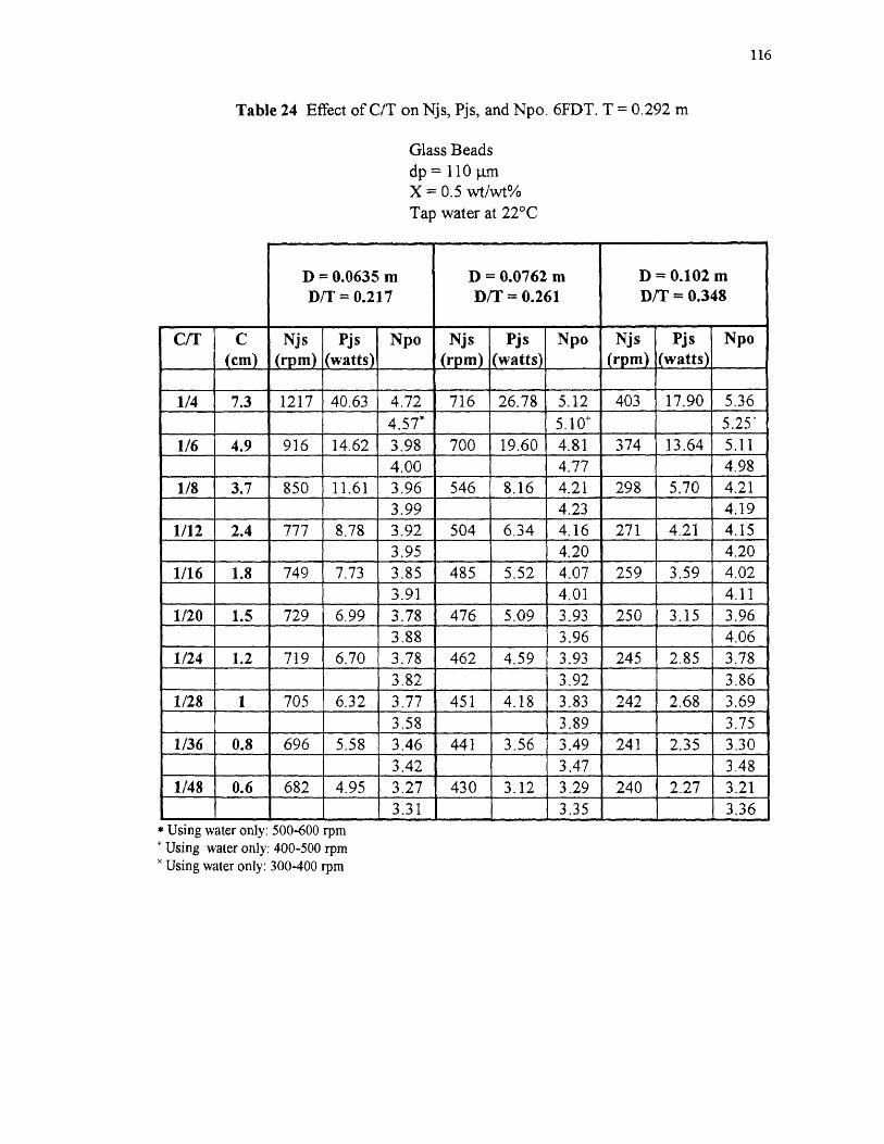
Table 24 Effect of C/T on Njs, Pjs, and Npo. 6FDT. T 0.292 m
Glass Beadsdp = 110 .t.mX = 0.5 wt/wt%Tap water at 22°C
116

Table 25 Effect of C'/D and C'/T on Njs, Pjs, and Npo. 6FDT. T = 0.292 m
Glass Beadsdp = 110 lamX 0.5 wt/wt%Tap water at 22°C
rvn (rim
117
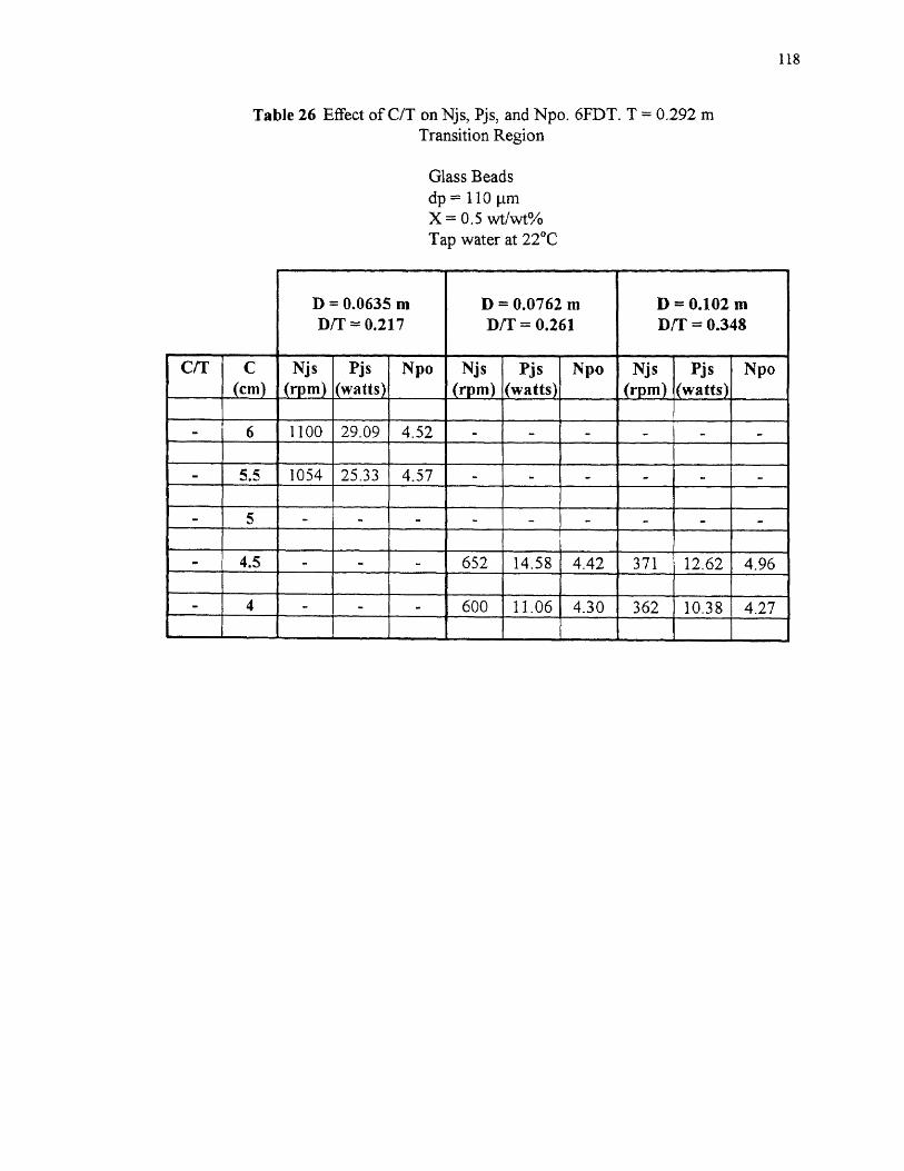
Table 26 Effect of C/T on Njs, Pjs, and Npo. 6FDT. T = 0.292 mTransition Region
Glass Beadsdp = 110 [trnX = 0.5 wt/wt%nr+
118
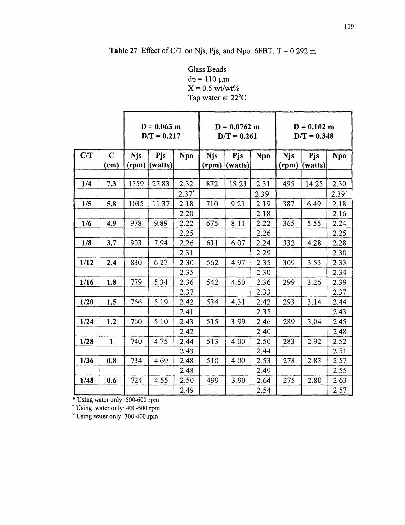
Table 27 Effect of C/T on Njs, Pjs, and Npo. 6FBT. T = 0.292 m
Glass Beadsdp = 110 pmX = 0.5 wt/wt%
119

Table 28 Effect of C'/D and C'IT on Njs, Pjs, and Npo. 6FBT. T = 0.292 m
Glass Beadsdp = 110 pmX = 0.5 wt/wt%Tap water at 22°C
C'/D (C/D)
120
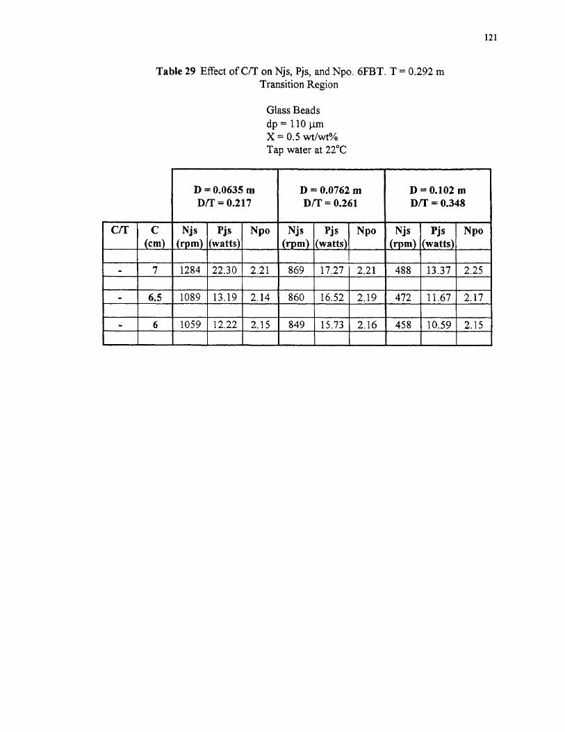
Table 29 Effect of C/T on Njs, Pjs, and Npo. 6FBT. T = 0.292 mTransition Region
Glass Beadsdp = 110 1..tmX = 0.5 wt/wt%Tap water at 22°C
121

Table 30 Effect of C/T on Njs, Pjs, and Npo. 6FPT. T = 0.292 m
Glass Beadsdp = 11011mX = 0.5 wt/wt%Tap water at 22°C
122
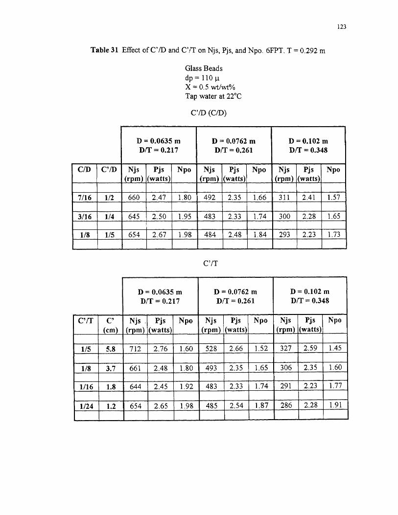
Table 31 Effect of C'/D and C'/T on Njs, Pjs, and Npo. 6FPT. T = 0,292 m
Glass Beadsdp = 110X = 0.5 wt/wt%Tap water at 22 °C
C'/D (CID)
123
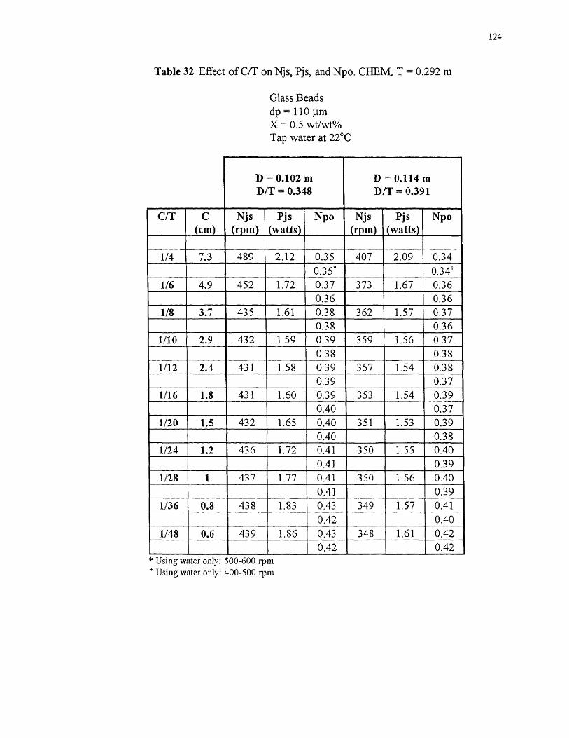
Table 32 Effect of C/T on Njs, Pjs, and Npo. CHEM. T = 0.292 m
Glass Beadsdp = 110 l_tmX = 0.5 wt/wt%Tap water at 22°C
124
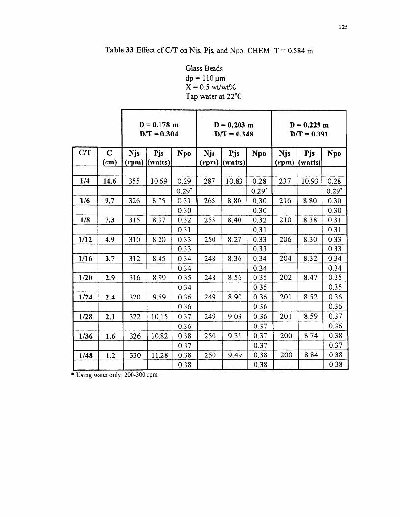
Table 33 Effect of C/T on Njs, Pjs, and Npo. CHEM. T = 0.584 m
Glass Beadsdp = 11011MX = 0.5 wt/wt%Tap water at 22°C
125

Table 34 Effect of C'/D on Njs, Pjs, and Npo. CHEM. T = 0.584 m
Glass Beadsdp = 110 p.mX = 0.5 wt/wt%Tap water at 22 °C
126

Table 35 Effect of T on Njs, Pjs, and Npo at Constant D/T (= 0.384). 6FDTConstant C/T (C'/T)
Glass Beadsdp = 110 pmX = 0.5 wt/wt%Tap water at 22°C
127

Table 36 Effect of T on Njs, Pjs, and Npo at Constant D (= 0.0762 m). 6FDTConstant C/T
Glass Beadsdp = 110 4mX = 0.5 wt/wt%Tao water at 22°C
128

Table 37 Effect of T on Njs, Pjs, and Npo at Constant D (= 0.0635 m). 6FDTConstant C/T
Glass Beadsdp = 110X = 0.5 wt/wt%Tan water at 22°C
129
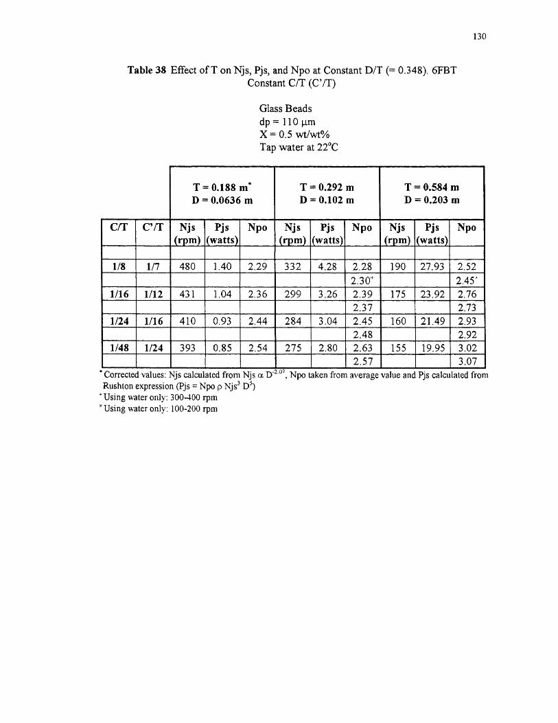
Table 38 Effect of T on Njs, Pjs, and Npo at Constant D/T (= 0.348). 6FBTConstant C/T (C'/T)
Glass Beadsdp = 110 pmX = 0.5 wt/wt%Tap water at 22 °C
130

Table 39 Effect of T on Njs, Pjs, and Npo at Constant D (= 0.0762 m). 6FBTConstant C/T
Glass Beadsdp = 110 .trriX = 0.5 wt/vvt%Tap water at 22°C
131

Table 40 Effect of T on Njs, Pjs, and Npo at Constant D (= 0.0635 m). 6FBTConstant C/T
Glass Beadsdp = 110 ilmX = 0.5 wt/wt%Tap water at 22°C
132
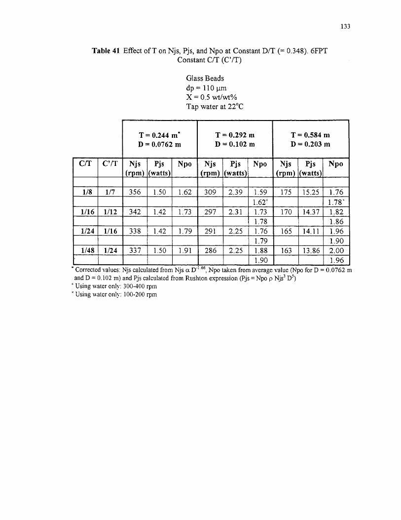
Table 41 Effect of T on Njs, Pjs, and Npo at Constant D/T (= 0.348). 6FPTConstant C/T (C'/T)
Glass Beadsdp = 110 pmX = 0.5 wt/wt%Tan water at 27°C
133

Table 42 Effect of T on Njs, Pjs, and Npo at Constant D (= 0.0762 m). 6FPTConstant C/T
Glass Beadsdp = 110 innX = 0.5 wt/wt%Tap water at 22°C
134
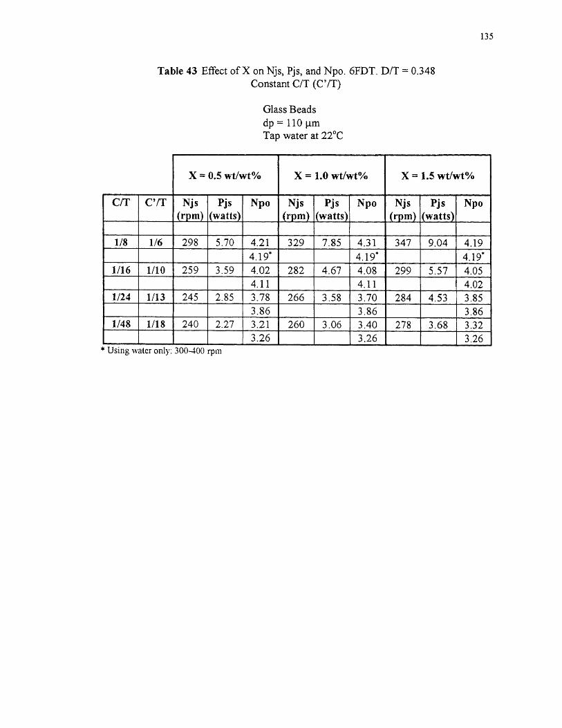
Table 43 Effect of X on Njs, Pjs, and Npo. 6FDT. D/T = 0.348Constant C/T (C'/T)
Glass Beadsdp = 110 p.mTap water at 22°C
135

Table 44 Effect of X on Njs, Pjs, and Npo. 6FBT. D/T = 0,348Constant CIT (C'/T)
Glass Beadsdp = HO pmTan -water at 22°C
136
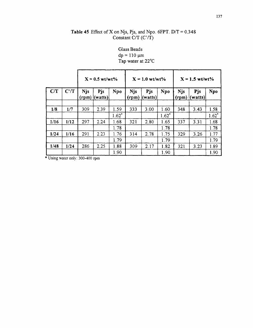
Table 45 Effect of X on Njs, Pjs, and Npo. 6FPT. D/T = 0.348Constant C/T (C'/T)
Glass Beadsdp = 110
137

Table 46 Effect of X on Njs, Pjs, and Npo. CHEM. D/T = 0.348Constant C/T (C'/T)
Glass Beadsdp = 110 p.mTap water at 22°C
138

Table 47 Dual-6FDT System. Effect of C/T on Njs, Pjs, and NpoT = 0.292 m, D/T = 0.261, S/D = 1
Glass Beadsdp = 110 [A,X = 0.5 wt/wt%Tan water at 22°C
139
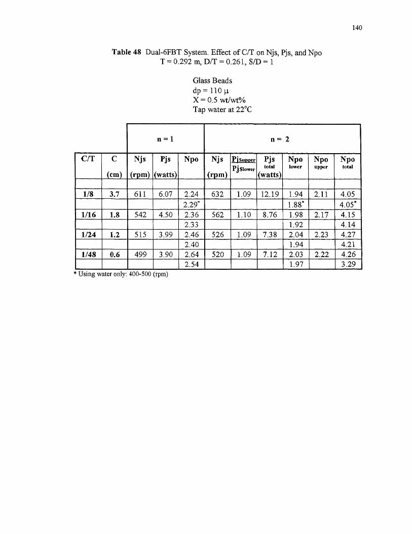
Table 48 Dual-6FBT System. Effect of C/T on Njs, Pjs, and NpoT = 0.292 m, D/T = 0.261, S/D = 1
Glass Beadsdp = 110 p,X = 0.5 wt/wt%Tap water at 22°C
140
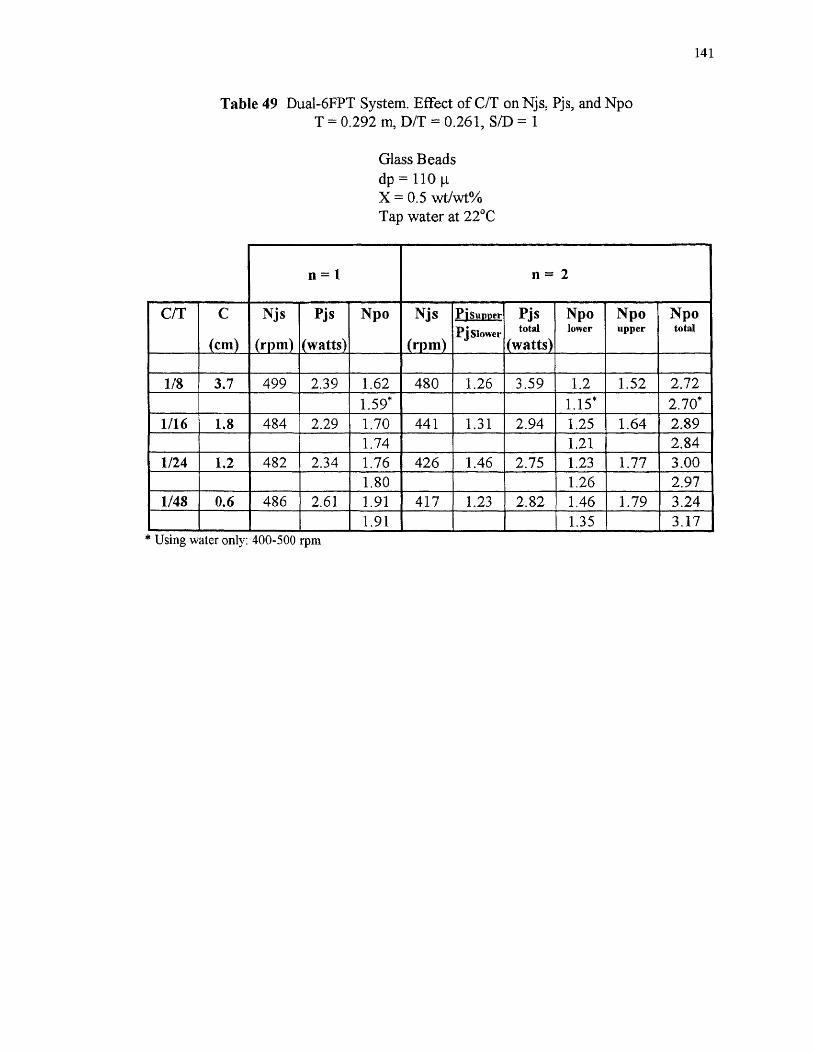
Table 49 Dual-6FPT System. Effect of C/T on Njs, Pjs, and NpoT = 0.292 m, D/T = 0.261, SID = 1
Glass Beadsdp = 110 p.X = 0.5 wt/wt%Tap water at 22°C
141
REFERENCES
Aravinth, S., Gangaghar Rao P., and Murugesan, T., 1996, Critical Impeller Speed forSolid Suspension in Turbine Agitated Contactors, Bioproc. Eng., 14: 97-99.
Armenante, P. M., and Li, T., 1993, Minimum Agitation Speed for Off-BottomSuspension of Solids in Agitated Vessels Provided with Multiple Flat-BladeImpellers, A.I.Ch.E. Symp. Ser., 89: 105-111.
Armenante, P. M., Huang, Y. T., and Li, T., 1992, Determination of the MinimumAgitation Speed to Attain the Just Dispersed State in Solid-Liquid and Liquid-Liquid Reactors Provided with Multiple Impellers, Chem. Eng. Sci., 47: 2865-2870.
Baldi, G., Conti, R., and Alaria, E., 1978, Complete Suspension of Particles inMechanically Agitated Vessels, Chem. Eng. Sci., 33: 21-25.
Bates, R. L., Fondy, P. L., and Corpstein, R. R., 1963, An Examination of SomeGeometric Parameters on Impeller Power, Ind. Eng. Chem. Process Des. Dev.,2:310-314.
Chang, G-M, 1993, Power Consumption in Single-Phase Agitated Vessels Provided withMultiple Impellers, M. S. Thesis, New Jersey Institute of Technology, Newark,NJ.
Chapman, C. M., Nienow, A. W., Cooke, M., and Middleton, J. C., 1983, Particle-Gas-Liquid Mixing in Stirred Vessels. Part I: Particle-Liquid Mixing, Trans. Inst.Chem. Eng., 61: 71-81.
Chudacek, M. W., 1985, Solids Suspension Behavior in Profiled Bottom and Flat BottomMixing Tanks, Chem. Eng. Sci., 40: 385-392.
Chudacek, M. W., 1986, Relationships between Solids Suspension Criteria, Mechanism ofSuspension, Tank Geometry, and Scale-Up Parameters in Stirred Tanks, Ind. Eng.Chem. Fundam., 25: 391-401.
Conti, R., Sicardi, S., and Specchia, V., 1981, Effect of the Stirrer Clearance onSuspension in Agitated Vessels, Chem. Eng. J., 22: 247-249.
Einenkel, W-D, 1980, Influence of Physical Properties and Equipment Design on theHomogeneity of Suspensions in Agitated Vessels, Ger. Chem. Eng., 3: 118-124.
142

143
Gray, D. J., 1987, Impeller Clearance Effect on Off-Bottom Particle Suspension inAgitated Vessels, Chem. Eng. Commun., 61: 151-158.
Gray, D. J., Treybal, R. E., and Barnett, S. M., 1982, Mixing of Single and Two PhaseSystems: Power Consumption of Impellers, A.I.Ch.E. 1., 28: 195-199.
Janzon, J., and Theliander, H., 1994, On the Suspension of Particles in an Agitated Vessel,Chem. Eng. Sci., 49: 3522 -3526.
Kolar, V., 1961, Studies on Mixing. X: Suspending Solid Particles in Liquids by means ofMechanical Agitation, Collec. Czech. Chem. Commun., 26: 613-627.
Molerus, M., and Latzel, W., 1987a, Suspension of Solid Particles in Agitated Vessels-I.Archimedes Number < 40, Chem. Eng. Sci., 42: 1423-1430.
Molerus, M., and Latzel, W., 1987b, Suspension of Solid Particles in Agitated Vessels-II.Archimedes Number > 40, Reliable Prediction of Minimum Stirrer AngularVelocities, Chem. Eng. Sci., 42: 1431-1437.
Musil, L., and Vlk, J., 1978, Suspending Solid Particles in an Agitated Conical-BottomTank, Cheni. Eng. Sci., 33: 1123-1131.
Musil, L., Vlk, J., and Jiroudkova, H., 1984, Suspending Solid Particles in an AgitatedTank with Axial-Type Impellers, Chem. Eng. Sci., 39: 621-627.
Myers, K. J., and Fasano, J. B., 1992, The Influence of Baffle Off-Bottom Clearance onthe Solids Suspension Performance of Pitched-Blade and High-EfficiencyImpellers, Can. J. Chem. Eng., 70: 596-599.
Myers, K. J., Corpstein, R. R., Bakker, A., and Fasano, J., 1994a, Solids SuspensionAgitator Design with Pitched-Blade and High-Efficiency Impellers, A.I.Ch.E.Symp. Ser., 90: 186 - 190.
Myers, K. 3., Fasano, J. B., and Corpstein, R. R., 1994b, The Influence of Solid Propertieson the Just-Suspended Agitation Requirements of Pitched-Blade and High-Efficiency Impellers, Can. J. Chem. Eng., 72: 745-748.
Narayanan, S., Bhathia, V. K., Guha, D. K., and Rao, M. N., 1969, Suspension of Solidsby Mechanical Agitation, Chem. Eng. Sci., 24: 223-230.
Nienow, A. W., 1968, Suspension of Solid Particles in Turbine-agitated, Baffled Vessels,Chem. Eng. Sci., 23: 1453 - 1459.
Nienow, A. W., and Miles, D., 1971, Impeller Power Numbers in Closed Vessels, Ind.Eng. Chem. Process Des. Dev., 10: 41 -43.

144
Nienow, A. W., and Miles, D., 1978, The Effect of Impeller/Tank Configurations onFluid-Particle Mass Transfer, Chem. Eng. J., 15: 13-24.
Niewow, A. W., 1985, The Dispersion of Solids in Liquids, in Mixing of Liquids byMechanical Agitation, by J. J. Ulbrecht and G. K. Patterson (editors), pp. 273-307, Gordon and Breach Science Publishers, London.
Oldshue, J. Y., 1983, Solids Suspensions, in Fluid Mixing Technology, pp. 94-124,McGraw-Hill, New York, NY.
Oldshue, J. Y., and Sharma, R. N., 1992, The Effect of Off-Bottom Distance of anImpeller for the "Just Suspended Speed", Njs, A.I. Ch.E. Symp. Ser., 88: 72-76.
O'Okane, K., 1974, The Effect of Geometric Parameters on the Power Consumption ofTurbine Impellers Operating in Non-viscous Fluids , Proc. 1st Europ. Conf onMixing, Cambridge, England, Sept. 9-11, paper A3: 23-31.
Raghava Rao, K. S. M. S., and Joshi, J. B., 1988a, Liquid Phase Mixing in MechanicallyAgitated Vessels, Chem. Eng. Commun., 74: 1-25.
Raghava Rao, K. S. M. S., Rewatkar, V. B., and Joshi, J. B., 1988b, Critical ImpellerSpeed for Solid Suspension in Mechanically Agitated Contactors, A.I.Ch.E. .1, 34:1332-1340.
Rewatkar, V. B., Raghava Rao, K. S. M. S., and Joshi, J. B., 1990, Power Consumptionin Mechanically Agitated Contactors Using Pitched Bladed Turbine Impeller,Chem. Eng. Commun., 88: 69-90.
Rieger, F., and Ditl, P., 1994, Suspension of Solid Particles, Chem. Eng. Sci., 49: 2219-2227.
Rushton, J. H., Costich, E. W., and Everett, H. J., 1950, Power Characteristics of MixingImpellers — Part I, Chem. Eng. Prog., 46: 395-404.
Weisman, J., and Efferding, L. E., 1960, Suspension of Slurries by Mechanical Mixers,A.I.Ch.E. J., 6: 419-426.
Wichterle, K., 1988, Conditions for Suspension of Solids in Agitated Vessels, Chem. Eng.Sci., 43: 467-471.
Zwietering, T. N., 1958, Suspending Solid Particles in Liquids by Agitators, Chem. Eng.Sci., 8: 244-253.
Related Documents