OPTO 22 • 800-321-6786 • 1-951-695-3000 • www.opto22.com • [email protected] © 2006–2018 Opto 22. All rights reserved. Dimensions and specifications are subject to change. Brand or product names used herein are trademarks or registered trademarks of their respective companies or organizations. DATA SHEET Form 0859-180904 SOLID-STATE RELAYS Features Rugged, epoxy encapsulation construction 4,000 volts of optical isolation Subjected to full load test and six times the rated current surge before and after encapsulation Unique heat-spreader technology Guaranteed for life OVERVIEW In 1974, Opto 22 introduced the first liquid epoxy-filled line of power solid-state relays (SSR). This innovation in SSR design greatly improved the reliability and reduced the cost of manufacturing. At that time, we also incorporated into our manufacturing process 100% testing under full-load conditions of every relay we produced. By 1978, Opto 22 had gained such a reputation for reliability that we were recognized as the world’s leading manufacturer of solid-state relays. Through continuous manufacturing improvements and the same 100% testing policy established over 40 years ago, Opto 22 is still recognized today for the very high quality and reliability of all our solid-state relays. DESCRIPTION Opto 22 offers a complete line of SSRs, from the rugged 120/240/380-volt AC Series to the small footprint MP Series, designed for mounting on printed circuit boards. All Opto 22 SSRs feature 4,000 volts of optical isolation, and most are UL and CSA recognized. The innovative use of room-temperature liquid epoxy encapsulation, coupled with Opto 22’s unique heat-spreader technology, are key to mass producing the world’s most reliable solid-state relays. > > > > > Opto 22 Power Series SSR Part Numbers Part Description AC Switching 120A10 120 VAC, 10 Amp, AC Control 120A25 120 VAC, 25 Amp, AC Control 240A10 240 VAC, 10 Amp, AC Control 240A25 240 VAC, 25 Amp, AC Control 240A45 240 VAC, 45 Amp, AC Control 120D3 120 VAC, 3 Amp, DC Control 120D10 120 VAC, 10 Amp, DC Control 120D25 120 VAC, 25 Amp, DC Control 120D45 120 VAC, 45 Amp, DC Control 240D3 240 VAC, 3 Amp, DC Control 240D10 240 VAC, 10 Amp, DC Control 240Di10 240 VAC, 10 Amp, DC Control, with LED Indicators 240D25 240 VAC, 25 Amp, DC Control 240Di25 240 VAC, 25 Amp, DC Control, with LED Indicators 240D30-HS 240 VAC, 30 Amp, DC Control, with integrated heatsink 240D45 240 VAC, 45 Amp, DC Control 240Di45 240 VAC, 45 Amp, DC Control, with LED Indicators 380D25 380 VAC, 25 Amp, DC Control 380D45 380 VAC, 45 Amp, DC Control 480D10-12 480 VAC, 10 Amp, DC Control, Transient Proof 480D15-12 480 VAC, 15 Amp, DC Control, Transient Proof 480D25-12 480 VAC, 25 Amp, DC Control, Transient Proof 480D25-HS 480 VAC, 25 Amp, DC Control, Transient Proof, with integrated heatsink 480D45-12 480 VAC, 45 Amp, DC Control, Transient Proof 575D15-12 575 VAC, 15 Amp, DC Control, Transient Proof 575D45-12 575 VAC, 45 Amp, DC Control, Transient Proof 575D30-HS 575 VAC, 30 Amp, DC Control, Transient Proof, with integrated heatsink 575Di45-12 575 VAC, 45 Amp, DC Control, Transient Proof, with LED Indicators MP120D2 or P120D2 120 VAC, 2 Amp, DC Control P model is low profile MP120D4 or P120D4 120 VAC, 4 Amp, DC Control P model is low profile MP240D2 or P240D2 240 VAC, 2 Amp, DC P model is low profile MP240D4 or P240D4 240 VAC, 4 Amp, DC P model is low profile MP380D4 380 VAC, 4 Amp, DC Z120D10 Z Model, 120 VAC, 10 Amp, DC Control Z240D10 Z Model, 240 VAC, 10 Amp, DC Control DC Switching DC60P or DC60MP 60 VDC, 3 Amp, DC Control P model is low profile DC200P or DC200MP 200 VDC, 1 Amp, DC Control P model is low profile DC60S-3 60 VDC, 3 Amp, DC Control DC60S-5 60 VDC, 5 Amp, DC Control Accessories SAFETY COVER Power Series SSR safety cover SSR-HS Power Series SSR heatsink SSR-THERMOPAD Thermal conductive pad (pack of 10) Part Description AC Switching

SOLID-STATE RELAYS Opto 22 Power Series SSR · OPTO 22 • 800-321-6786 • 1-951-695-3000 • • [email protected] DATA SHEET + ...
Nov 10, 2018
Welcome message from author
This document is posted to help you gain knowledge. Please leave a comment to let me know what you think about it! Share it to your friends and learn new things together.
Transcript
OPTO 22 • 800-321-6786 • 1-951-695-3000 • www.opto22.com • [email protected]
© 2006–2018 Opto 22. All rights reserved. Dimensions and specifications are subject to change. Brand or product names used herein are trademarks or registered trademarks of their respective companies or organizations.
PAGE 1
DATA SHEETForm 0859-180904
SOLID-STATE RELAYS
FeaturesRugged, epoxy encapsulation construction
4,000 volts of optical isolation
Subjected to full load test and six times the rated current surge before and after encapsulation
Unique heat-spreader technology
Guaranteed for life
OVERVIEWIn 1974, Opto 22 introduced the first liquid epoxy-filled line of power
solid-state relays (SSR). This innovation in SSR design greatly improved
the reliability and reduced the cost of manufacturing. At that time, we
also incorporated into our manufacturing process 100% testing under
full-load conditions of every relay we produced.
By 1978, Opto 22 had gained such a reputation for reliability that we
were recognized as the world’s leading manufacturer of solid-state
relays. Through continuous manufacturing improvements and the
same 100% testing policy established over 40 years ago, Opto 22 is
still recognized today for the very high quality and reliability of all our
solid-state relays.
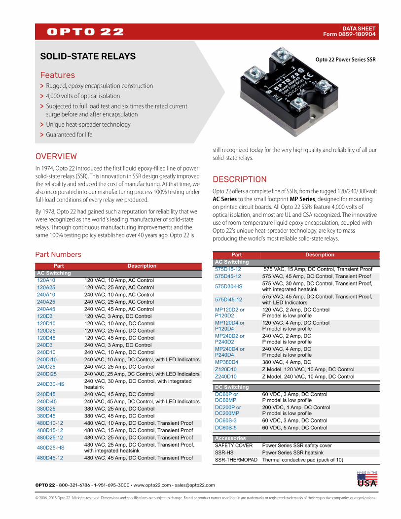
DESCRIPTIONOpto 22 offers a complete line of SSRs, from the rugged 120/240/380-volt
AC Series to the small footprint MP Series, designed for mounting
on printed circuit boards. All Opto 22 SSRs feature 4,000 volts of
optical isolation, and most are UL and CSA recognized. The innovative
use of room-temperature liquid epoxy encapsulation, coupled with
Opto 22’s unique heat-spreader technology, are key to mass
producing the world’s most reliable solid-state relays.
>>>
>>
Opto 22 Power Series SSR
Part Numbers
Part DescriptionAC Switching120A10 120 VAC, 10 Amp, AC Control120A25 120 VAC, 25 Amp, AC Control240A10 240 VAC, 10 Amp, AC Control240A25 240 VAC, 25 Amp, AC Control240A45 240 VAC, 45 Amp, AC Control120D3 120 VAC, 3 Amp, DC Control120D10 120 VAC, 10 Amp, DC Control120D25 120 VAC, 25 Amp, DC Control120D45 120 VAC, 45 Amp, DC Control240D3 240 VAC, 3 Amp, DC Control240D10 240 VAC, 10 Amp, DC Control240Di10 240 VAC, 10 Amp, DC Control, with LED Indicators240D25 240 VAC, 25 Amp, DC Control240Di25 240 VAC, 25 Amp, DC Control, with LED Indicators
240D30-HS 240 VAC, 30 Amp, DC Control, with integrated heatsink
240D45 240 VAC, 45 Amp, DC Control240Di45 240 VAC, 45 Amp, DC Control, with LED Indicators380D25 380 VAC, 25 Amp, DC Control380D45 380 VAC, 45 Amp, DC Control480D10-12 480 VAC, 10 Amp, DC Control, Transient Proof480D15-12 480 VAC, 15 Amp, DC Control, Transient Proof480D25-12 480 VAC, 25 Amp, DC Control, Transient Proof
480D25-HS 480 VAC, 25 Amp, DC Control, Transient Proof, with integrated heatsink
480D45-12 480 VAC, 45 Amp, DC Control, Transient Proof
575D15-12 575 VAC, 15 Amp, DC Control, Transient Proof575D45-12 575 VAC, 45 Amp, DC Control, Transient Proof
575D30-HS 575 VAC, 30 Amp, DC Control, Transient Proof, with integrated heatsink
575Di45-12 575 VAC, 45 Amp, DC Control, Transient Proof, with LED Indicators
MP120D2 or P120D2
120 VAC, 2 Amp, DC ControlP model is low profile
MP120D4 or P120D4
120 VAC, 4 Amp, DC ControlP model is low profile
MP240D2 or P240D2
240 VAC, 2 Amp, DCP model is low profile
MP240D4 or P240D4
240 VAC, 4 Amp, DCP model is low profile
MP380D4 380 VAC, 4 Amp, DCZ120D10 Z Model, 120 VAC, 10 Amp, DC ControlZ240D10 Z Model, 240 VAC, 10 Amp, DC Control
DC SwitchingDC60P or DC60MP
60 VDC, 3 Amp, DC ControlP model is low profile
DC200P or DC200MP
200 VDC, 1 Amp, DC ControlP model is low profile
DC60S-3 60 VDC, 3 Amp, DC ControlDC60S-5 60 VDC, 5 Amp, DC Control
AccessoriesSAFETY COVER Power Series SSR safety coverSSR-HS Power Series SSR heatsinkSSR-THERMOPAD Thermal conductive pad (pack of 10)
Part DescriptionAC Switching

PAGE 2
OPTO 22 • 800-321-6786 • 1-951-695-3000 • www.opto22.com • [email protected]
© 2006–2018 Opto 22. All rights reserved. Dimensions and specifications are subject to change. Brand or product names used herein are trademarks or registered trademarks of their respective companies or organizations.
DATA SHEETForm 0859-180904
Every Opto 22 solid-state relay is subjected to full load test and six
times the rated current surge both before and after encapsulation.
This double testing of every part before it leaves the factory means
you can rely on Opto 22 solid-state relays. All Opto 22 SSRs are
guaranteed for life.
Accessories for the Power-Series SSRs include a safety cover, a
heatsink, and a matching thermal conductive pad. See page 3.
Power Series SSRs
Opto 22 provides a full range of Power
Series relays with a wide variety of voltage
(120–575 volts) and current options (3–45
amps). All Power Series relays feature 4,000
volts of optical isolation and have a high
PRV rating. Some Power Series relays
include built-in LEDs to indicate operation.
See page 4.
DC Series
The DC Series delivers isolated DC control to large OEM customers
worldwide. All DC control SSRs are LS TTL compatible.
AC Series
The AC Series offers the ultimate in solid state reliability. All AC Power
Series relays feature a built-in snubber as well as zero-voltage turn-on
and zero-current turn-off. Transient-proof models offer self protection
for noisy electrical environments.
Z Series SSRs
The Z Series employs a unique heat transfer
system that makes it possible for Opto 22
to deliver a low-cost, 10-amp, solid-state
relay in an all-plastic case. The push-on,
tool-free quick-connect terminals make the
Z Series ideal for high-volume OEM
applications. Operating temperature:
–40 °C to 100 °C. See page 7.
Printed Circuit Series SSRs
Opto 22’s Printed Circuit Series allows
OEMs to easily deploy solid-state relays on
printed circuit boards. Two unique
packages are available, both of which will
switch loads up to four amps. Operating
temperature: –40 °C to 100 °C. See page 9.
MP Series
The MP Series packaging is designed with a minimum footprint to
allow maximum relay density on the printed circuit board.
P Series
The P Series power relays provide low-profile [0.5 in. (12.7 mm)]
center mounting on printed circuit boards.
HS Series SSRs
The HS Series features an integrated heatsink,
which makes them so cool. These relays have
less thermal resistance inside, so heat
dissipates more easily than in a standard SSR
mounted to the same heatsink. With the
heatsink built-in, you don't have to select
one from a catalog, and installation is much
easier. Includes a DIN-rail adapter. See
page 13.
SPECIFICATIONS(ALL POWER SERIES MODELS)• 4,000 V optical isolation, input to output
• Zero voltage turn-on
• Zero-current turn-off
• Turn-on time: 0.5 cycle maximum
• Turn-off time: 0.5 cycle maximum
• Operating temperature: –40 °C to 100 °C
• Operating frequency: 25 to 65 Hz
(operates at 400 Hz with six times off-state leakage)
• Coupling capacitance, input to output: 8 pF maximum
• Hermetically sealed
• DV/DT Off-state: 200 volts per microsecond
• DV/DT commutating: snubbed for rated current at 0.5 power
factor
• UL recognized
• CSA certified
• CE component
• Torque specs for screws (this spec is both the recommended
torque and the maximum torque you should use):
Control terminals, 10 in-lb (1.13 N-m)
Field terminals, 18 in-lb (2.03 N-m)
OPTO 22 • 800-321-6786 • 1-951-695-3000 • www.opto22.com • [email protected]
© 2006–2018 Opto 22. All rights reserved. Dimensions and specifications are subject to change. Brand or product names used herein are trademarks or registered trademarks of their respective companies or organizations.
PAGE 3
DATA SHEETForm 0859-180904
POWER SERIES SSR ACCESSORIES
Safety Cover
A plastic safety cover (Opto 22 part number SAFETY COVER) is
available for use with Opto 22 Power Series SSRs. The safety cover
reduces the chance of accidental contact with relay terminals, while
providing access holes for test instrumentation.
SSR-HS Heatsink
Custom designed for the Power Series SSRs, the SSR-HS heatsink
provides excellent heat dissipation when mounted to the SSR with a
matching thermal conductive pad, used in place of silicon grease.
One thermal pad is included with the heatsink. Additional pads may
be purchased in packs of 10 (part number SSR-THERMOPAD).
DIN-rail adapter is included.
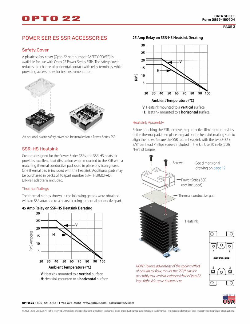
Thermal Ratings
The thermal ratings shown in the following graphs were obtained
with an SSR attached to a heatsink using a thermal conductive pad.
45 Amp Relay on SSR-HS Heatsink Derating
25 Amp Relay on SSR-HS Heatsink Derating
Heatsink Assembly
Before attaching the SSR, remove the protective film from both sides
of the thermal pad, then place the pad on the heatsink making sure to
align the holes. Secure the SSR to the heatsink with the two 8-32 x
3/8˝ panhead Phillips screws included in the kit. Use 20 in-lb (2.26
N-m) of torque.
An optional plastic safety cover can be installed on a Power Series SSR.
V
H
30
25
20
15
10
5
30 40 50 60 70 80 90 10020
Ambient Temperature (°C)
RMS
Am
per
es
V: Heatsink mounted to a vertical surface
H: Heatsink mounted to a horizontal surface.
30
25
20
15
10
5
30 40 50 60 70 80 90 10020
Ambient Temperature (°C)
RM
S
V
H
V: Heatsink mounted to a vertical surface
H: Heatsink mounted to a horizontal surface.
NOTE: To take advantage of the cooling effect
of natural air flow, mount the SSR/heatsink
assembly to a vertical surface with the Opto 22
logo right side up as shown here.
Screws
Thermal conductive pad
Power Series SSR
(not included)
Heatsink
See dimensional
drawing on page 12.
PAGE 4
OPTO 22 • 800-321-6786 • 1-951-695-3000 • www.opto22.com • [email protected]
© 2006–2018 Opto 22. All rights reserved. Dimensions and specifications are subject to change. Brand or product names used herein are trademarks or registered trademarks of their respective companies or organizations.
DATA SHEETForm 0859-180904
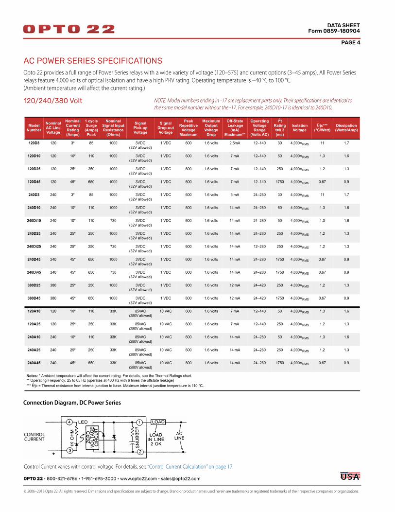
AC POWER SERIES SPECIFICATIONSOpto 22 provides a full range of Power Series relays with a wide variety of voltage (120–575) and current options (3–45 amps). All Power Series
relays feature 4,000 volts of optical isolation and have a high PRV rating. Operating temperature is –40 °C to 100 °C.
(Ambient temperature will affect the current rating.)
ModelNumber
NominalAC LineVoltage
NominalCurrentRating(Amps)
1 cycleSurge
(Amps)Peak
NominalSignal InputResistance
(Ohms)
SignalPick-upVoltage
SignalDrop-outVoltage
PeakRepetitive
VoltageMaximum
MaximumOutputVoltage
Drop
Off-State Leakage
(mA)Maximum**
OperatingVoltageRange
(Volts AC)
I2tRatingt=8.3(ms)
IsolationVoltage
jc***(°C/Watt)
Dissipation(Watts/Amp)
120D3 120 3* 85 1000 3VDC(32V allowed)
1 VDC 600 1.6 volts 2.5mA 12–140 30 4,000VRMS 11 1.7
120D10 120 10* 110 1000 3VDC(32V allowed)
1 VDC 600 1.6 volts 7 mA 12–140 50 4,000VRMS 1.3 1.6
120D25 120 25* 250 1000 3VDC(32V allowed)
1 VDC 600 1.6 volts 7 mA 12–140 250 4,000VRMS 1.2 1.3
120D45 120 45* 650 1000 3VDC(32V allowed)
1 VDC 600 1.6 volts 7 mA 12–140 1750 4,000VRMS 0.67 0.9
240D3 240 3* 85 1000 3VDC(32V allowed)
1 VDC 600 1.6 volts 5 mA 24–280 30 4,000VRMS 11 1.7
240D10 240 10* 110 1000 3VDC(32V allowed)
1 VDC 600 1.6 volts 14 mA 24–280 50 4,000VRMS 1.3 1.6
240Di10 240 10* 110 730 3VDC(32V allowed)
1 VDC 600 1.6 volts 14 mA 24–280 50 4,000VRMS 1.3 1.6
240D25 240 25* 250 1000 3VDC(32V allowed)
1 VDC 600 1.6 volts 14 mA 24–280 250 4,000VRMS 1.2 1.3
240Di25 240 25* 250 730 3VDC(32V allowed)
1 VDC 600 1.6 volts 14 mA 12–280 250 4,000VRMS 1.2 1.3
240D45 240 45* 650 1000 3VDC(32V allowed)
1 VDC 600 1.6 volts 14 mA 24–280 1750 4,000VRMS 0.67 0.9
240Di45 240 45* 650 730 3VDC(32V allowed)
1 VDC 600 1.6 volts 14 mA 24–280 1750 4,000VRMS 0.67 0.9
380D25 380 25* 250 1000 3VDC(32V allowed)
1 VDC 800 1.6 volts 12 mA 24–420 250 4,000VRMS 1.2 1.3
380D45 380 45* 650 1000 3VDC(32V allowed)
1 VDC 800 1.6 volts 12 mA 24–420 1750 4,000VRMS 0.67 0.9
120A10 120 10* 110 33K 85VAC(280V allowed)
10 VAC 600 1.6 volts 7 mA 12–140 50 4,000VRMS 1.3 1.6
120A25 120 25* 250 33K 85VAC(280V allowed)
10 VAC 600 1.6 volts 7 mA 12–140 250 4,000VRMS 1.2 1.3
240A10 240 10* 110 33K 85VAC(280V allowed)
10 VAC 600 1.6 volts 14 mA 24–280 50 4,000VRMS 1.3 1.6
240A25 240 25* 250 33K 85VAC(280V allowed)
10 VAC 600 1.6 volts 14 mA 24–280 250 4,000VRMS 1.2 1.3
240A45 240 45* 650 33K 85VAC(280V allowed)
10 VAC 600 1.6 volts 14 mA 24–280 1750 4,000VRMS 0.67 0.9
Notes: * Ambient temperature will affect the current rating. For details, see the Thermal Ratings chart. ** Operating Frequency: 25 to 65 Hz (operates at 400 Hz with 6 times the offstate leakage)***jc = Thermal resistance from internal junction to base. Maximum internal junction temperature is 110 °C.
120/240/380 Volt
Connection Diagram, DC Power Series
Control Current varies with control voltage. For details, see “Control Current Calculation” on page 17.
NOTE: Model numbers ending in -17 are replacement parts only. Their specifications are identical to
the same model number without the -17. For example, 240D10-17 is identical to 240D10.
OPTO 22 • 800-321-6786 • 1-951-695-3000 • www.opto22.com • [email protected]
© 2006–2018 Opto 22. All rights reserved. Dimensions and specifications are subject to change. Brand or product names used herein are trademarks or registered trademarks of their respective companies or organizations.
PAGE 5
DATA SHEETForm 0859-180904
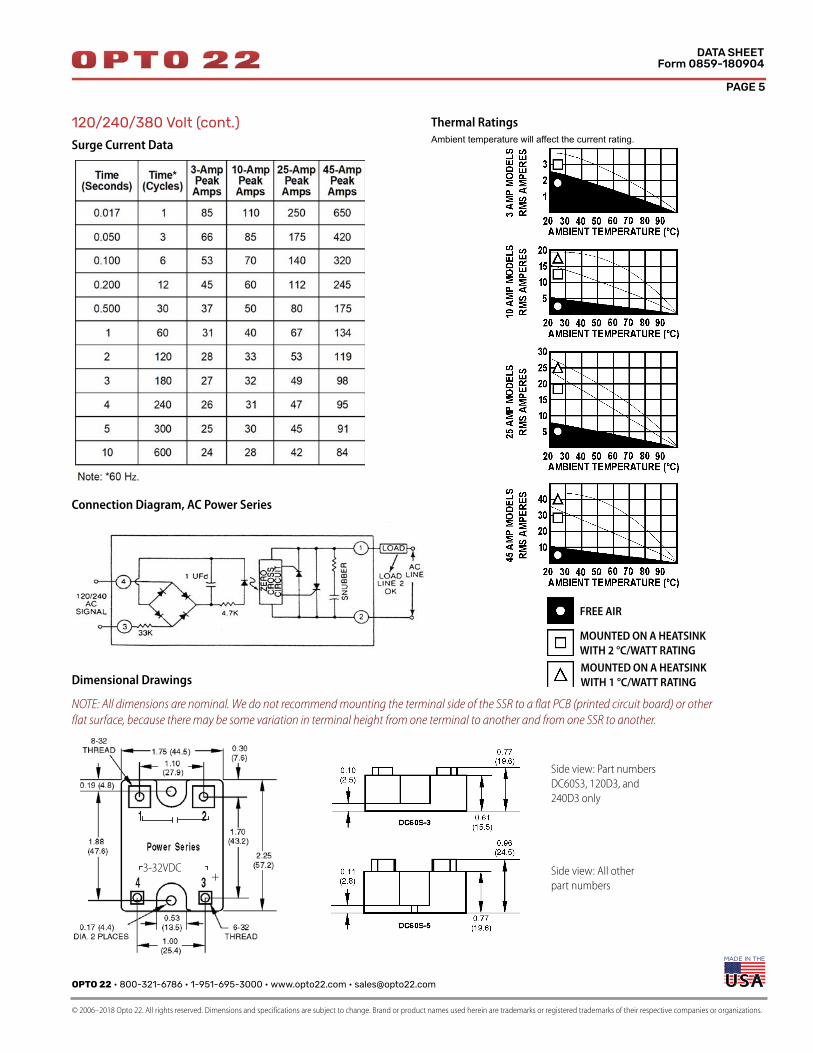
120/240/380 Volt (cont.)
Surge Current Data
Connection Diagram, AC Power Series
Thermal Ratings
Ambient temperature will affect the current rating.
MOUNTED ON A HEATSINK
WITH 2 °C/WATT RATING
MOUNTED ON A HEATSINK
WITH 1 °C/WATT RATING
FREE AIR
Side view: Part numbers
DC60S3, 120D3, and
240D3 only
Side view: All other
part numbers+
3-32VDC
Dimensional Drawings
NOTE: All dimensions are nominal. We do not recommend mounting the terminal side of the SSR to a flat PCB (printed circuit board) or other
flat surface, because there may be some variation in terminal height from one terminal to another and from one SSR to another.
Side view: Part numbers
DC60S3, 120D3, and
240D3 only
Side view: All other
part numbers+
3-32VDC
PAGE 6
OPTO 22 • 800-321-6786 • 1-951-695-3000 • www.opto22.com • [email protected]
© 2006–2018 Opto 22. All rights reserved. Dimensions and specifications are subject to change. Brand or product names used herein are trademarks or registered trademarks of their respective companies or organizations.
DATA SHEETForm 0859-180904
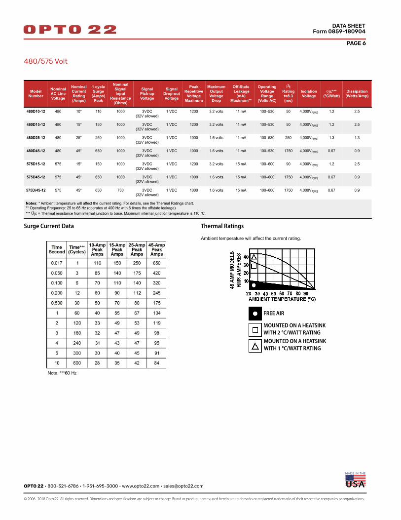
480/575 Volt
Surge Current Data Thermal Ratings
Ambient temperature will affect the current rating.
ModelNumber
NominalAC LineVoltage
NominalCurrentRating(Amps)
1 cycleSurge
(Amps)Peak
NominalSignal Input
Resistance(Ohms)
SignalPick-upVoltage
SignalDrop-outVoltage
PeakRepetitive
VoltageMaximum
MaximumOutputVoltage
Drop
Off-State Leakage
(mA)Maximum**
OperatingVoltageRange
(Volts AC)
I2tRatingt=8.3(ms)
IsolationVoltage
jc***(°C/Watt)
Dissipation(Watts/Amp)
480D10-12 480 10* 110 1000 3VDC(32V allowed)
1 VDC 1200 3.2 volts 11 mA 100–530 50 4,000VRMS 1.2 2.5
480D15-12 480 15* 150 1000 3VDC(32V allowed)
1 VDC 1200 3.2 volts 11 mA 100–530 50 4,000VRMS 1.2 2.5
480D25-12 480 25* 250 1000 3VDC(32V allowed)
1 VDC 1000 1.6 volts 11 mA 100–530 250 4,000VRMS 1.3 1.3
480D45-12 480 45* 650 1000 3VDC(32V allowed)
1 VDC 1000 1.6 volts 11 mA 100–530 1750 4,000VRMS 0.67 0.9
575D15-12 575 15* 150 1000 3VDC(32V allowed)
1 VDC 1200 3.2 volts 15 mA 100–600 90 4,000VRMS 1.2 2.5
575D45-12 575 45* 650 1000 3VDC(32V allowed)
1 VDC 1000 1.6 volts 15 mA 100–600 1750 4,000VRMS 0.67 0.9
575Di45-12 575 45* 650 730 3VDC(32V allowed)
1 VDC 1000 1.6 volts 15 mA 100–600 1750 4,000VRMS 0.67 0.9
Notes: * Ambient temperature will affect the current rating. For details, see the Thermal Ratings chart. ** Operating Frequency: 25 to 65 Hz (operates at 400 Hz with 6 times the offstate leakage)***jc = Thermal resistance from internal junction to base. Maximum internal junction temperature is 110 °C.
MOUNTED ON A HEATSINK
WITH 2 °C/WATT RATING
MOUNTED ON A HEATSINK
WITH 1 °C/WATT RATING
FREE AIR
OPTO 22 • 800-321-6786 • 1-951-695-3000 • www.opto22.com • [email protected]
© 2006–2018 Opto 22. All rights reserved. Dimensions and specifications are subject to change. Brand or product names used herein are trademarks or registered trademarks of their respective companies or organizations.
PAGE 7
DATA SHEETForm 0859-180904
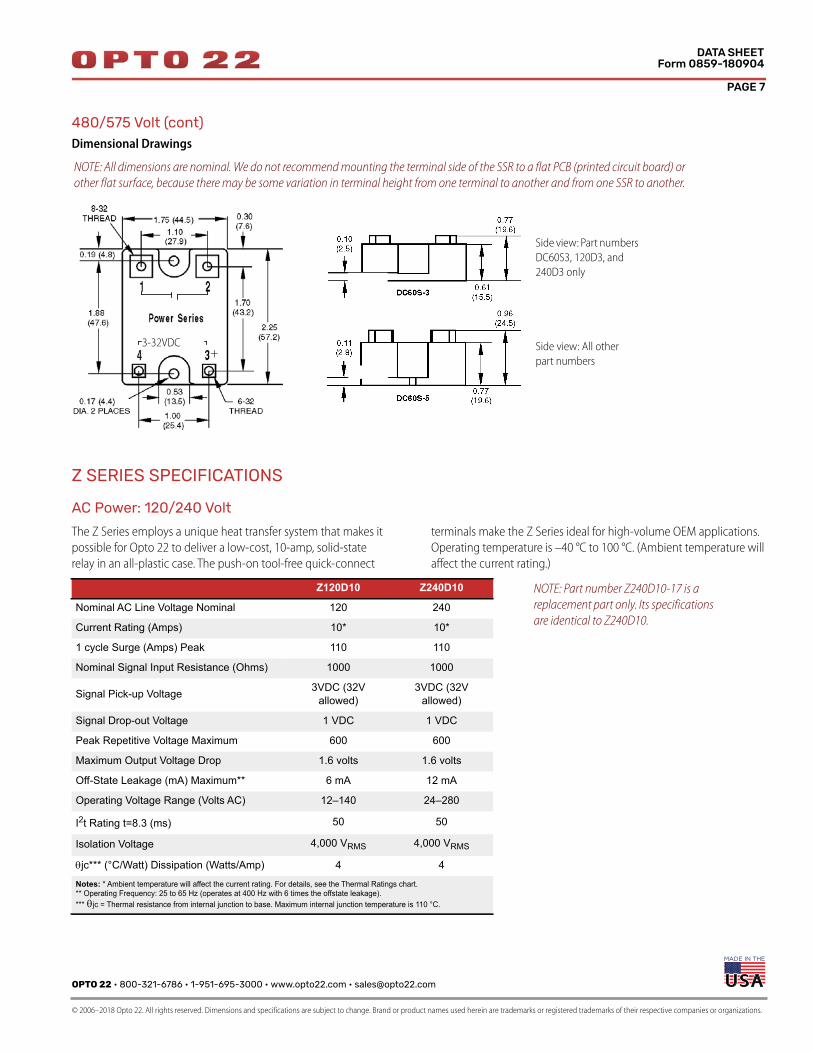
480/575 Volt (cont)Dimensional Drawings
Z SERIES SPECIFICATIONS
AC Power: 120/240 Volt
The Z Series employs a unique heat transfer system that makes it
possible for Opto 22 to deliver a low-cost, 10-amp, solid-state
relay in an all-plastic case. The push-on tool-free quick-connect
terminals make the Z Series ideal for high-volume OEM applications.
Operating temperature is –40 °C to 100 °C. (Ambient temperature will
affect the current rating.)
Side view: Part numbers
DC60S3, 120D3, and
240D3 only
Side view: All other
part numbers+
3-32VDC
NOTE: All dimensions are nominal. We do not recommend mounting the terminal side of the SSR to a flat PCB (printed circuit board) or
other flat surface, because there may be some variation in terminal height from one terminal to another and from one SSR to another.
Z120D10 Z240D10
Nominal AC Line Voltage Nominal 120 240
Current Rating (Amps) 10* 10*
1 cycle Surge (Amps) Peak 110 110
Nominal Signal Input Resistance (Ohms) 1000 1000
Signal Pick-up Voltage 3VDC (32V allowed)
3VDC (32V allowed)
Signal Drop-out Voltage 1 VDC 1 VDC
Peak Repetitive Voltage Maximum 600 600
Maximum Output Voltage Drop 1.6 volts 1.6 volts
Off-State Leakage (mA) Maximum** 6 mA 12 mA
Operating Voltage Range (Volts AC) 12–140 24–280
I2t Rating t=8.3 (ms) 50 50
Isolation Voltage 4,000 VRMS 4,000 VRMS
jc*** (°C/Watt) Dissipation (Watts/Amp) 4 4
Notes: * Ambient temperature will affect the current rating. For details, see the Thermal Ratings chart. ** Operating Frequency: 25 to 65 Hz (operates at 400 Hz with 6 times the offstate leakage).***jc = Thermal resistance from internal junction to base. Maximum internal junction temperature is 110 °C.
NOTE: Part number Z240D10-17 is a
replacement part only. Its specifications
are identical to Z240D10.
PAGE 8
OPTO 22 • 800-321-6786 • 1-951-695-3000 • www.opto22.com • [email protected]
© 2006–2018 Opto 22. All rights reserved. Dimensions and specifications are subject to change. Brand or product names used herein are trademarks or registered trademarks of their respective companies or organizations.
DATA SHEETForm 0859-180904
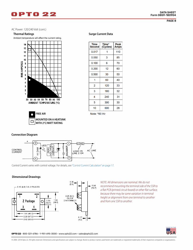
AC Power: 120/240 Volt (cont.)
Connection Diagram
Thermal Ratings
Ambient temperature will affect the current rating.
Surge Current Data
MOUNTED ON A HEATSINK
WITH 2°C/WATT RATING
FREE AIR
Control Current varies with control voltage. For details, see “Control Current Calculation” on page 17.
Dimensional Drawings
NOTE: All dimensions are nominal. We do not
recommend mounting the terminal side of the SSR to
a flat PCB (printed circuit board) or other flat surface,
because there may be some variation in terminal
height or alignment from one terminal to another
and from one SSR to another.
OPTO 22 • 800-321-6786 • 1-951-695-3000 • www.opto22.com • [email protected]
© 2006–2018 Opto 22. All rights reserved. Dimensions and specifications are subject to change. Brand or product names used herein are trademarks or registered trademarks of their respective companies or organizations.
PAGE 9
DATA SHEETForm 0859-180904
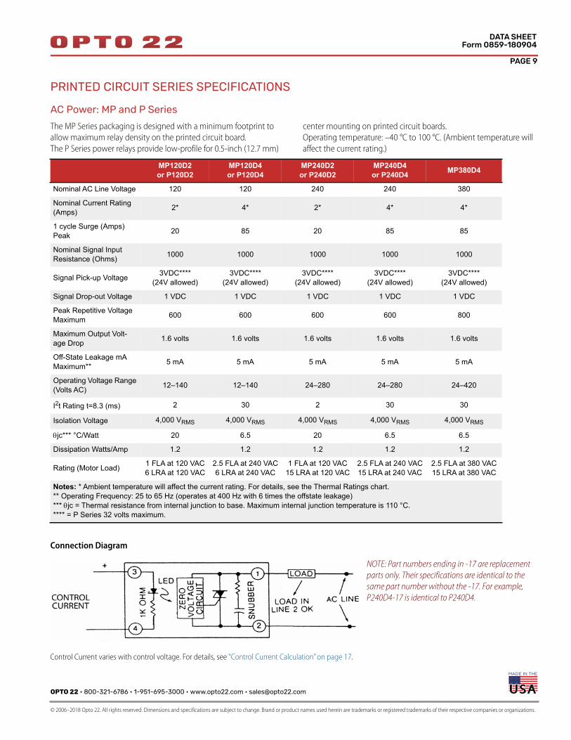
PRINTED CIRCUIT SERIES SPECIFICATIONS
AC Power: MP and P Series
The MP Series packaging is designed with a minimum footprint to
allow maximum relay density on the printed circuit board.
The P Series power relays provide low-profile for 0.5-inch (12.7 mm)
center mounting on printed circuit boards.
Operating temperature: –40 °C to 100 °C. (Ambient temperature will
affect the current rating.)
Connection Diagram
MP120D2 or P120D2
MP120D4 or P120D4
MP240D2 or P240D2
MP240D4 or P240D4 MP380D4
Nominal AC Line Voltage 120 120 240 240 380
Nominal Current Rating (Amps) 2* 4* 2* 4* 4*
1 cycle Surge (Amps) Peak 20 85 20 85 85
Nominal Signal InputResistance (Ohms) 1000 1000 1000 1000 1000
Signal Pick-up Voltage 3VDC****(24V allowed)
3VDC****(24V allowed)
3VDC****(24V allowed)
3VDC****(24V allowed)
3VDC****(24V allowed)
Signal Drop-out Voltage 1 VDC 1 VDC 1 VDC 1 VDC 1 VDC
Peak Repetitive Voltage Maximum 600 600 600 600 800
Maximum Output Volt-age Drop 1.6 volts 1.6 volts 1.6 volts 1.6 volts 1.6 volts
Off-State Leakage mA Maximum** 5 mA 5 mA 5 mA 5 mA 5 mA
Operating Voltage Range (Volts AC) 12–140 12–140 24–280 24–280 24–420
I2t Rating t=8.3 (ms) 2 30 2 30 30
Isolation Voltage 4,000 VRMS 4,000 VRMS 4,000 VRMS 4,000 VRMS 4,000 VRMS
jc*** °C/Watt 20 6.5 20 6.5 6.5
Dissipation Watts/Amp 1.2 1.2 1.2 1.2 1.2
Rating (Motor Load) 1 FLA at 120 VAC6 LRA at 120 VAC
2.5 FLA at 240 VAC6 LRA at 240 VAC
1 FLA at 120 VAC15 LRA at 120 VAC
2.5 FLA at 240 VAC15 LRA at 240 VAC
2.5 FLA at 380 VAC15 LRA at 380 VAC
Notes: * Ambient temperature will affect the current rating. For details, see the Thermal Ratings chart.** Operating Frequency: 25 to 65 Hz (operates at 400 Hz with 6 times the offstate leakage)***jc = Thermal resistance from internal junction to base. Maximum internal junction temperature is 110 °C.**** = P Series 32 volts maximum.
NOTE: Part numbers ending in -17 are replacement
parts only. Their specifications are identical to the
same part number without the -17. For example,
P240D4-17 is identical to P240D4.
Control Current varies with control voltage. For details, see “Control Current Calculation” on page 17.
PAGE 10
OPTO 22 • 800-321-6786 • 1-951-695-3000 • www.opto22.com • [email protected]
© 2006–2018 Opto 22. All rights reserved. Dimensions and specifications are subject to change. Brand or product names used herein are trademarks or registered trademarks of their respective companies or organizations.
DATA SHEETForm 0859-180904
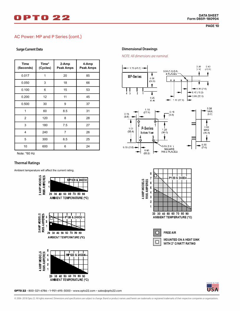
AC Power: MP and P Series (cont.)
Thermal Ratings
Ambient temperature will affect the current rating.
Surge Current Data
Time (Seconds)
Time*(Cycles)
2-AmpPeak Amps
4-AmpPeak Amps
0.017 1 20 85
0.050 3 18 66
0.100 6 15 53
0.200 12 11 45
0.500 30 9 37
1 60 8.5 31
2 120 8 28
3 180 7.5 27
4 240 7 26
5 300 6.5 25
10 600 6 24
Note: *60 Hz
Dimensional Drawings
NOTE: All dimensions are nominal.
OPTO 22 • 800-321-6786 • 1-951-695-3000 • www.opto22.com • [email protected]
© 2006–2018 Opto 22. All rights reserved. Dimensions and specifications are subject to change. Brand or product names used herein are trademarks or registered trademarks of their respective companies or organizations.
PAGE 11
DATA SHEETForm 0859-180904
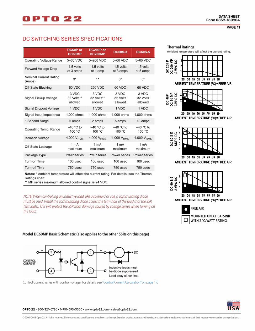
DC SWITCHING SERIES SPECIFICATIONS
Model DC60MP Basic Schematic (also applies to the other SSRs on this page)
NOTE: When controlling an inductive load, like a solenoid or coil, a commutating diode
must be used. Install the commutating diode across the terminals of the load (not the SSR
terminals). This will protect the SSR from damage caused by voltage spikes when turning off
the load.
DC60P or DC60MP
DC200P or DC200MP DC60S-3 DC60S-5
Operating Voltage Range 5–60 VDC 5–200 VDC 5–60 VDC 5–60 VDC
Forward Voltage Drop 1.5 voltsat 3 amps
1.5 volts at 1 amp
1.5 volts at 3 amps
1.5 volts at 5 amps
Nominal Current Rating (Amps) 3* 1* 3* 5*
Off-State Blocking 60 VDC 250 VDC 60 VDC 60 VDC
Signal Pickup Voltage3 VDC
32 Volts** allowed
3 VDC 32 Volts**allowed
3 VDC 32 Voltsallowed
3 VDC 32 Voltsallowed
Signal Dropout Voltage 1 VDC 1 VDC 1 VDC 1 VDC
Signal Input Impedance 1,000 ohms 1,000 ohms 1,000 ohms 1,000 ohms
1 Second Surge 5 amps 2 amps 5 amps 10 amps
Operating Temp. Range –40 °C to 100 °C
–40 °C to100 °C
–40 °C to100 °C
–40 °C to100 °C
Isolation Voltage 4,000 VRMS 4,000 VRMS 4,000 VRMS 4,000 VRMS
Off-State Leakage 1 mA maximum
1 mAmaximum
1 mAmaximum
1 mAmaximum
Package Type P/MP series P/MP series Power series Power series
Turn-on Time 100 usec 100 usec 100 usec 100 usec
Turn-off Time 750 usec 750 usec 750 usec 750 usec
Notes: * Ambient temperature will affect the current rating. For details, see the Thermal Ratings chart.** MP series maximum allowed control signal is 24 VDC.
Thermal RatingsAmbient temperature will affect the current rating.
MOUNTED ON A HEATSINK
WITH 2 °C/WATT RATING
FREE AIR
Control Current varies with control voltage. For details, see “Control Current Calculation” on page 17.
PAGE 12
OPTO 22 • 800-321-6786 • 1-951-695-3000 • www.opto22.com • [email protected]
© 2006–2018 Opto 22. All rights reserved. Dimensions and specifications are subject to change. Brand or product names used herein are trademarks or registered trademarks of their respective companies or organizations.
DATA SHEETForm 0859-180904
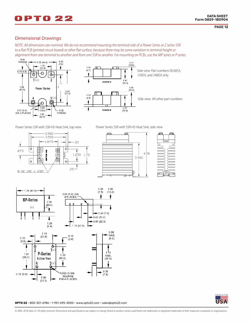
Dimensional Drawings
NOTE: All dimensions are nominal. We do not recommend mounting the terminal side of a Power Series or Z series SSR
to a flat PCB (printed circuit board) or other flat surface, because there may be some variation in terminal height or
alignment from one terminal to another and from one SSR to another. For mounting on PCBs, use the MP series or P series.
Side view: Part numbers DC60S3,
120D3, and 240D3 only
Side view: All other part numbers(+)
(+)
(+) (+)
(+)
(+)
Power Series SSR with SSR-HS Heat Sink, top view Power Series SSR with SSR-HS Heat Sink, side view
OPTO 22 • 800-321-6786 • 1-951-695-3000 • www.opto22.com • [email protected]
© 2006–2018 Opto 22. All rights reserved. Dimensions and specifications are subject to change. Brand or product names used herein are trademarks or registered trademarks of their respective companies or organizations.
PAGE 13
DATA SHEETForm 0859-180904
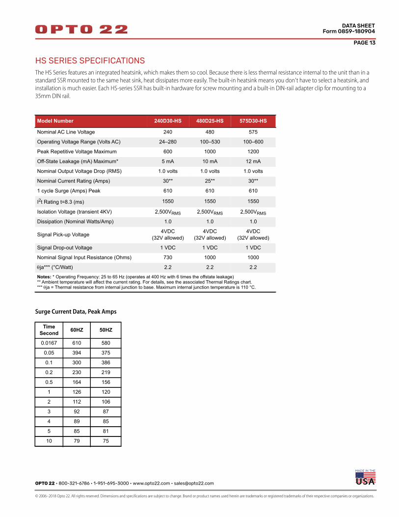
HS SERIES SPECIFICATIONSThe HS Series features an integrated heatsink, which makes them so cool. Because there is less thermal resistance internal to the unit than in a
standard SSR mounted to the same heat sink, heat dissipates more easily. The built-in heatsink means you don't have to select a heatsink, and
installation is much easier. Each HS-series SSR has built-in hardware for screw mounting and a built-in DIN-rail adapter clip for mounting to a
35mm DIN rail.
Surge Current Data, Peak Amps
Model Number 240D30-HS 480D25-HS 575D30-HS
Nominal AC Line Voltage 240 480 575
Operating Voltage Range (Volts AC) 24–280 100–530 100–600
Peak Repetitive Voltage Maximum 600 1000 1200
Off-State Leakage (mA) Maximum* 5 mA 10 mA 12 mA
Nominal Output Voltage Drop (RMS) 1.0 volts 1.0 volts 1.0 volts
Nominal Current Rating (Amps) 30** 25** 30**
1 cycle Surge (Amps) Peak 610 610 610
I2t Rating t=8.3 (ms) 1550 1550 1550
Isolation Voltage (transient 4KV) 2,500VRMS 2,500VRMS 2,500VRMS
Dissipation (Nominal Watts/Amp) 1.0 1.0 1.0
Signal Pick-up Voltage 4VDC (32V allowed)
4VDC(32V allowed)
4VDC(32V allowed)
Signal Drop-out Voltage 1 VDC 1 VDC 1 VDC
Nominal Signal Input Resistance (Ohms) 730 1000 1000
ja*** (°C/Watt) 2.2 2.2 2.2
Notes: * Operating Frequency: 25 to 65 Hz (operates at 400 Hz with 6 times the offstate leakage)** Ambient temperature will affect the current rating. For details, see the associated Thermal Ratings chart.*** ja = Thermal resistance from internal junction to base. Maximum internal junction temperature is 110 °C.
Time Second 60HZ 50HZ
0.0167 610 580
0.05 394 375
0.1 300 386
0.2 230 219
0.5 164 156
1 126 120
2 112 106
3 92 87
4 89 85
5 85 81
10 79 75

PAGE 14
OPTO 22 • 800-321-6786 • 1-951-695-3000 • www.opto22.com • [email protected]
© 2006–2018 Opto 22. All rights reserved. Dimensions and specifications are subject to change. Brand or product names used herein are trademarks or registered trademarks of their respective companies or organizations.
DATA SHEETForm 0859-180904
HS-SERIES (CONT.)Thermal Ratings
Ambient temperature will affect the current rating.
A
B
A: Single relay or with 0.75” spacing between relays. Derate above 40 °C; subtract 0.5 amp/°C.
B: Three relays side by side with 0.25” spacing. All relays with the same load. Derate above 40 °C; subtract 0.4 amp/°C.
30
25
20
15
10
5
30 40 50 60 70 80 90 10020
Ambient Temperature (°C)
30
Am
p M
od
els
RM
S A
mp
eres
30
25
20
15
10
5
30 40 50 60 70 80 90 10020
Ambient Temperature (°C)
25
Am
p M
od
els
RM
S A
mp
eres
NOTE: This data is for SSRs mounted to a horizontal surface. To take advantage
of the cooling effect of natural air flow, we recommend mounting HS-series SSRs
to a vertical surface with the Opto 22 logo right side up as shown here.
A
B
3.21" (81.6 mm)
3.90" (99.1 mm)
3.50" (88.9 mm) 0.20" (5.1 mm)
1.25"(31.8 mm)
4.81"(122.2 mm)
1.75"(44.5 mm)
0.25"(6.4 mm)
Dimensional Drawing
OPTO 22 • 800-321-6786 • 1-951-695-3000 • www.opto22.com • [email protected]
© 2006–2018 Opto 22. All rights reserved. Dimensions and specifications are subject to change. Brand or product names used herein are trademarks or registered trademarks of their respective companies or organizations.
PAGE 15
DATA SHEETForm 0859-180904
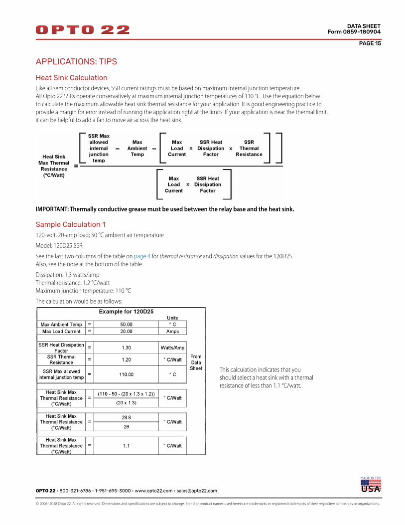
APPLICATIONS: TIPS
Heat Sink CalculationLike all semiconductor devices, SSR current ratings must be based on maximum internal junction temperature.
All Opto 22 SSRs operate conservatively at maximum internal junction temperatures of 110 °C. Use the equation below
to calculate the maximum allowable heat sink thermal resistance for your application. It is good engineering practice to
provide a margin for error instead of running the application right at the limits. If your application is near the thermal limit,
it can be helpful to add a fan to move air across the heat sink.
IMPORTANT: Thermally conductive grease must be used between the relay base and the heat sink.
Sample Calculation 1120-volt, 20-amp load; 50 °C ambient air temperature
Model: 120D25 SSR.
See the last two columns of the table on page 4 for thermal resistance and dissipation values for the 120D25.
Also, see the note at the bottom of the table.
Dissipation: 1.3 watts/amp
Thermal resistance: 1.2 °C/watt
Maximum junction temperature: 110 °C
The calculation would be as follows:
This calculation indicates that you
should select a heat sink with a thermal
resistance of less than 1.1 °C/watt.
PAGE 16
OPTO 22 • 800-321-6786 • 1-951-695-3000 • www.opto22.com • [email protected]
© 2006–2018 Opto 22. All rights reserved. Dimensions and specifications are subject to change. Brand or product names used herein are trademarks or registered trademarks of their respective companies or organizations.
DATA SHEETForm 0859-180904
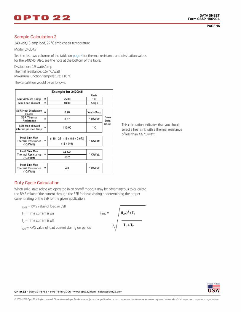
Sample Calculation 2240-volt,18-amp load, 25 °C ambient air temperature
Model: 240D45
See the last two columns of the table on page 4 for thermal resistance and dissipation values
for the 240D45. Also, see the note at the bottom of the table.
Dissipation: 0.9 watts/amp
Thermal resistance: 0.67 °C/watt
Maximum junction temperature: 110 °C
The calculation would be as follows:
Duty Cycle CalculationWhen solid-state relays are operated in an on/off mode, it may be advantageous to calculate
the RMS value of the current through the SSR for heat sinking or determining the proper
current rating of the SSR for the given application.
This calculation indicates that you should
select a heat sink with a thermal resistance
of less than 4.6 °C/watt.
IRMS = RMS value of load or SSR
T1 = Time current is on
T2 = Time current is off
ION = RMS value of load current during on period
IRMS =
T1 + T2
(ION)2 x T1
OPTO 22 • 800-321-6786 • 1-951-695-3000 • www.opto22.com • [email protected]
© 2006–2018 Opto 22. All rights reserved. Dimensions and specifications are subject to change. Brand or product names used herein are trademarks or registered trademarks of their respective companies or organizations.
PAGE 17
DATA SHEETForm 0859-180904
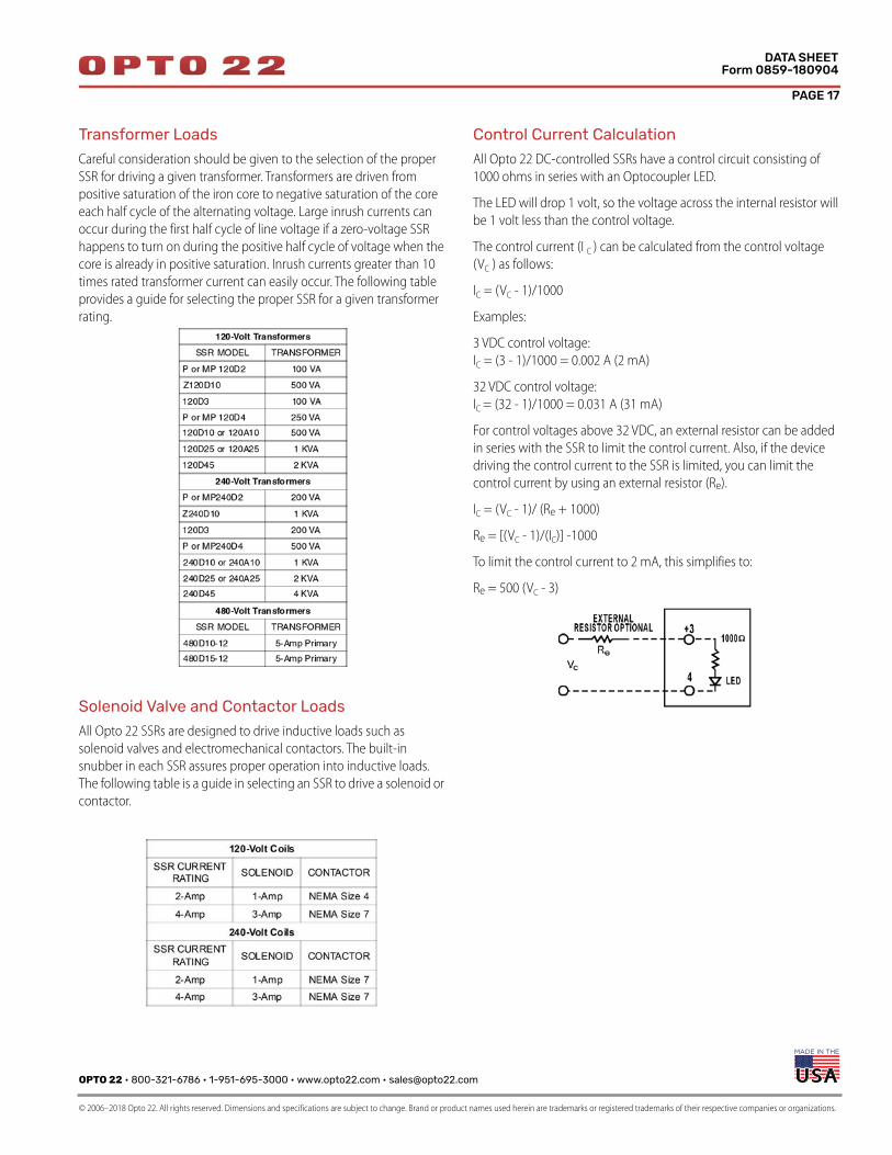
Transformer Loads
Careful consideration should be given to the selection of the proper
SSR for driving a given transformer. Transformers are driven from
positive saturation of the iron core to negative saturation of the core
each half cycle of the alternating voltage. Large inrush currents can
occur during the first half cycle of line voltage if a zero-voltage SSR
happens to turn on during the positive half cycle of voltage when the
core is already in positive saturation. Inrush currents greater than 10
times rated transformer current can easily occur. The following table
provides a guide for selecting the proper SSR for a given transformer
rating.
Solenoid Valve and Contactor Loads
All Opto 22 SSRs are designed to drive inductive loads such as
solenoid valves and electromechanical contactors. The built-in
snubber in each SSR assures proper operation into inductive loads.
The following table is a guide in selecting an SSR to drive a solenoid or
contactor.
Control Current Calculation
All Opto 22 DC-controlled SSRs have a control circuit consisting of
1000 ohms in series with an Optocoupler LED.
The LED will drop 1 volt, so the voltage across the internal resistor will
be 1 volt less than the control voltage.
The control current (I C ) can be calculated from the control voltage
(VC ) as follows:
IC = (VC - 1)/1000
Examples:
3 VDC control voltage:
IC = (3 - 1)/1000 = 0.002 A (2 mA)
32 VDC control voltage:
IC = (32 - 1)/1000 = 0.031 A (31 mA)
For control voltages above 32 VDC, an external resistor can be added
in series with the SSR to limit the control current. Also, if the device
driving the control current to the SSR is limited, you can limit the
control current by using an external resistor (Re).
IC = (VC - 1)/ (Re + 1000)
Re = [(VC - 1)/(IC)] -1000
To limit the control current to 2 mA, this simplifies to:
Re = 500 (VC - 3)
PAGE 18
OPTO 22 • 800-321-6786 • 1-951-695-3000 • www.opto22.com • [email protected]
© 2006–2018 Opto 22. All rights reserved. Dimensions and specifications are subject to change. Brand or product names used herein are trademarks or registered trademarks of their respective companies or organizations.
DATA SHEETForm 0859-180904
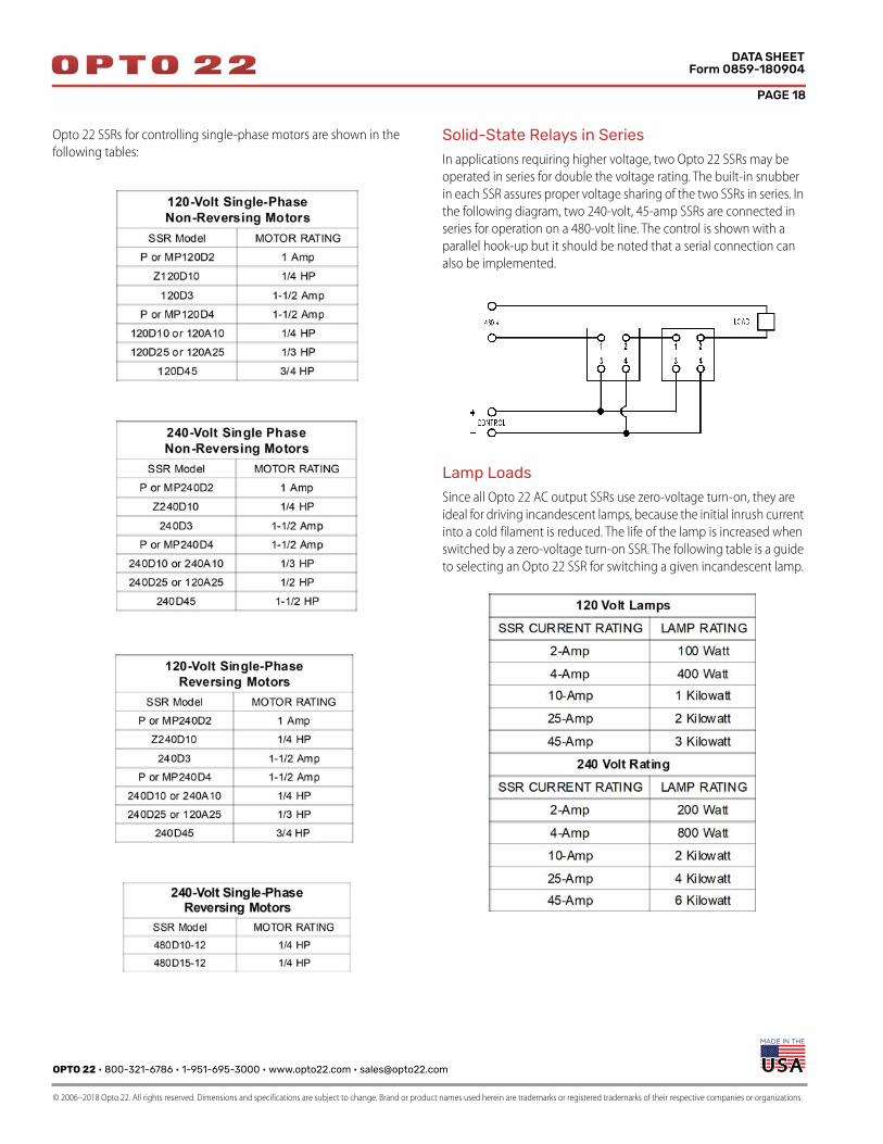
Opto 22 SSRs for controlling single-phase motors are shown in the
following tables:Solid-State Relays in Series
In applications requiring higher voltage, two Opto 22 SSRs may be
operated in series for double the voltage rating. The built-in snubber
in each SSR assures proper voltage sharing of the two SSRs in series. In
the following diagram, two 240-volt, 45-amp SSRs are connected in
series for operation on a 480-volt line. The control is shown with a
parallel hook-up but it should be noted that a serial connection can
also be implemented.
Lamp Loads
Since all Opto 22 AC output SSRs use zero-voltage turn-on, they are
ideal for driving incandescent lamps, because the initial inrush current
into a cold filament is reduced. The life of the lamp is increased when
switched by a zero-voltage turn-on SSR. The following table is a guide
to selecting an Opto 22 SSR for switching a given incandescent lamp.
OPTO 22 • 800-321-6786 • 1-951-695-3000 • www.opto22.com • [email protected]
© 2006–2018 Opto 22. All rights reserved. Dimensions and specifications are subject to change. Brand or product names used herein are trademarks or registered trademarks of their respective companies or organizations.
PAGE 19
DATA SHEETForm 0859-180904
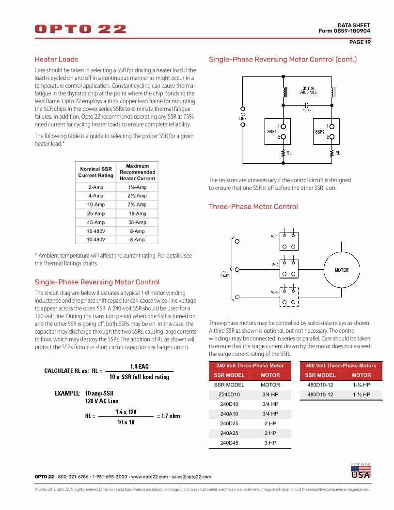
Heater Loads
Care should be taken in selecting a SSR for driving a heater load if the
load is cycled on and off in a continuous manner as might occur in a
temperature control application. Constant cycling can cause thermal
fatigue in the thyristor chip at the point where the chip bonds to the
lead frame. Opto 22 employs a thick copper lead frame for mounting
the SCR chips in the power series SSRs to eliminate thermal fatigue
failures. In addition, Opto 22 recommends operating any SSR at 75%
rated current for cycling heater loads to ensure complete reliability.
The following table is a guide to selecting the proper SSR for a given
heater load.*
* Ambient temperature will affect the current rating. For details, see
the Thermal Ratings charts.
Single-Phase Reversing Motor Control
The circuit diagram below illustrates a typical 1 Ø motor winding
inductance and the phase shift capacitor can cause twice-line voltage
to appear across the open SSR. A 240-volt SSR should be used for a
120-volt line. During the transition period when one SSR is turned on
and the other SSR is going off, both SSRs may be on. In this case, the
capacitor may discharge through the two SSRs, causing large currents
to flow, which may destroy the SSRs. The addition of RL as shown will
protect the SSRs from the short circuit capacitor discharge current.
Single-Phase Reversing Motor Control (cont.)
The resistors are unnecessary if the control circuit is designed
to ensure that one SSR is off before the other SSR is on.
Three-Phase Motor Control
Three-phase motors may be controlled by solid-state relays as shown.
A third SSR as shown is optional, but not necessary. The control
windings may be connected in series or parallel. Care should be taken
to ensure that the surge current drawn by the motor does not exceed
the surge current rating of the SSR.
240 Volt Three-Phase Motor 480 Volt Three-Phase Motors
SSR MODEL MOTOR SSR MODEL MOTOR
SSR MODEL MOTOR 480D10-12 1-½ HP
Z240D10 3/4 HP 480D15-12 1-½ HP
240D10 3/4 HP
240A10 3/4 HP
240D25 2 HP
240A25 2 HP
240D45 3 HP
PAGE 20
OPTO 22 • 800-321-6786 • 1-951-695-3000 • www.opto22.com • [email protected]
© 2006–2018 Opto 22. All rights reserved. Dimensions and specifications are subject to change. Brand or product names used herein are trademarks or registered trademarks of their respective companies or organizations.
DATA SHEETForm 0859-180904
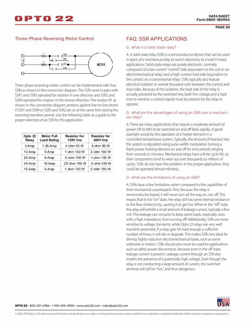
Three-Phase Reversing Motor Control
Three-phase reversing motor control can be implemented with four
SSRs as shown in the connection diagram. The SSRs work in pairs with
SSR1 and SSR3 operated for rotation in one direction and SSR2 and
SSR4 operated for rotation in the reverse direction. The resistor R1 as
shown in the connection diagram protects against line-to-line shorts
if SSR1 and SSR4 or SSR3 and SSR2 are on at the same time during the
reversing transition period. Use the following table as a guide to the
proper selection of an SSR for this application.
FAQ: SSR APPLICATIONS
Q : What is a solid-state relay?
A: A solid-state relay (SSR) is a semiconductor device that can be used
in place of a mechanical relay to switch electricity to a load in many
applications. Solid-state relays are purely electronic, normally
composed of a low current “control” side (equivalent to the coil on an
electromechanical relay) and a high-current load side (equivalent to
the contact on a conventional relay). SSRs typically also feature
electrical isolation to several thousand volts between the control and
load sides. Because of this isolation, the load side of the relay is
actually powered by the switched line; both line voltage and a load
(not to mention a control signal) must be present for the relay to
operate.
Q : What are the advantages of using an SSR over a mechani-cal relay?
A: There are many applications that require a moderate amount of
power (W to kW) to be switched on and off fairly rapidly. A good
example would be the operation of a heater element in a
controlled-temperature system. Typically, the amount of heat put into
the system is regulated using pulse-width modulation turning a
fixed-power heating element on and off for time periods ranging
from seconds to minutes. Mechanical relays have a finite cycle life, as
their components tend to wear out over thousands to millions of
cycles. SSRs do not have this problem; in the proper application, they
could be operated almost infinitely.
Q : What are the limitations of using an SSR?
A: SSRs have a few limitations when compared to the capabilities of
their mechanical counterparts. First, because the relay is
semiconductor-based, it will never turn all the way on, nor off. This
means that in the “on” state, the relay still has some internal resistance
to the flow of electricity, causing it to get hot. When in the “off” state,
the relay will exhibit a small amount of leakage current, typically a few
mA. This leakage can conspire to keep some loads, especially ones
with a high impedance, from turning off! Additionally, SSRs are more
sensitive to voltage transients; while Opto 22 relays are very well
transient-protected, if a relay gets hit hard enough a sufficient
number of times, it will die or degrade. This makes SSRs less ideal for
driving highly inductive electromechanical loads, such as some
solenoids or motors. SSRs should also never be used for applications
such as safety power disconnects, because even in the off state,
leakage current is present. Leakage current through an SSR also
implies the presence of a potentially high voltage. Even though the
relay is not conducting a large amount of current, the switched
terminal will still be “hot,” and thus dangerous.
OPTO 22 • 800-321-6786 • 1-951-695-3000 • www.opto22.com • [email protected]
© 2006–2018 Opto 22. All rights reserved. Dimensions and specifications are subject to change. Brand or product names used herein are trademarks or registered trademarks of their respective companies or organizations.
PAGE 21
DATA SHEETForm 0859-180904
Q: Which SSRs should I use with a printed circuit board (PCB)?
A: If you are mounting SSRs to a PCB, use the MP or P series SSRs
which are designed for that purpose.
We do not recommend mounting the terminal side of a Power Series
or Z series SSR to a flat PCB (or to any other flat surface), because there
may be some variation in terminal height or alignment from one
terminal to another and from one SSR to another.
Q : Do you make multi-pole or multi-throw SSRs?
A: Opto 22 manufactures only single-pole, single-throw SSRs. If
multi-phase operation is required, just use a relay on each phase.
Because of the limitations on semiconductor devices of the type used
in SSRs, it is not practical to build single-device multi-throw SSRs.
However, an alternative to multi-throw operation may be
accomplished with multiple relays.
Q : Can I hook up SSRs in parallel to achieve a higher current rating?
A: No. There is no way to guarantee that two or more relays will turn
on simultaneously when operated in parallel. Each relay requires a
minimum voltage across the output terminals to function; because of
the optical isolation feature, the “contact” part of the SSR is actually
powered by the line it switches. One relay turning on before the other
will cause the second relay to lose its turn-on voltage, and it won’t
ever turn on, or at least not until the first relay fails from carrying too
much current.
Q : What does a “zero-crossing” turn-on circuit refer to?
A: An AC sine wave will be positive for the first half of each cycle and
negative for the second half of each cycle. The voltage will cross
through zero when the sine wave changes from the positive
half-cycle to the negative half-cycle, and vice versa. So the voltage
crosses through zero twice with each full AC sine wave cycle.
“Zero-crossing” turn-on means that the SSR will only turn on when
the AC sine wave passes through zero voltage. The actual turn-on will
occur at or near zero voltage. All Opto 22 AC output solid-state relays
are designed with a zero-crossing turn-on circuit. Zero-voltage
turn-on has the benefit of minimizing electrical noise. All Opto 22 AC
output solid-state relays use a zero-current turn-off circuit as well.
Q : Can I use an AC SSR to switch DC?
A: No. Because of the zero-crossing circuit described above, the relay
will most likely never turn on, and even if it is on, it will most likely not
be able to be turned off.
Q : Can I use a DC SSR to switch AC?
A: No. The semiconductor device used in Opto 22’s DC SSRs is
polarized. It may break down and conduct for the portion of the
waveform that is reversed in polarity.
Q : Can a DC SSR be used to switch an analog signal?
A: This is not recommended at all. First, the voltage drop across the
relay will cause signal loss. Second, the conduction characteristics of
the SSR are very non-linear at low operating voltages and currents.
Use a mechanical relay; it will work much better.
Q : What agency approvals do your SSRs carry?
A: In general, Opto 22 relays carry UL, CSA, and CE approval. See
http://support.opto22.com. Additionally, some SSRs contain
VDE-approved optocouplers; contact Opto 22 for more information.
FAQ: SSR TROUBLESHOOTING
Q : My SSR does not function anymore. What may have hap-pened?
A: There is no “normal” mode of failure for SSRs. They just stop
working, by refusing to turn on or off. An improper installation is often
to blame for an SSR failure, as these are very simple, reliable devices. If
you have a failed SSR, it is important to look at the normal operating
parameters of that relay within the larger system to make sure that the
relay being used is appropriate to the application, and that the relay is
being properly installed in the system. The three most common
causes of SSR failure are as follows:
• SSR improperly matched to load. The relay was destroyed by
overheating from carrying too much current too long.
• SSR insufficiently protected. Remember, a semiconductor is
less tough than a simple metal contact. Reverse voltages
exceeding the PRV rating of the relay will cause damage. Voltage
spikes on the switched line, perhaps from inductive kickback, may
have destroyed one or more of the internal switching devices.
Remember to use snubbers, transorbs, MOVs, and/or
commutating diodes on highly inductive loads.
• SSR improperly installed. The SSR was not mounted to a large
enough heat sink, or no thermal compound was used, causing
the relay to overheat. Also, insufficient tightening of the load
terminals can cause arcing and ohmic heating of the relay.
Opto 22 recommends 18 inch-pounds of torque on the load
screw terminals. Similar failures have also been attributed to the
use of crimp-on terminal lugs or spades; make sure such terminals
are tightly crimped, and even drip some solder into the joint to
ensure good electrical contact and protection from corrosion.
Q : How can I test my SSR?
A: It is not possible to test an SSR by the same methods used to test
mechanical relays; a typical SSR will always show an infinite
impedance to a resistance meter placed across the output terminals.
There are a few reasons for this. First, the SSR requires a small amount
of power to operate, derived from whatever voltage source is placed
PAGE 22
OPTO 22 • www.opto22.com SALES • [email protected] SUPPORT • [email protected] Business Park Dr. Temecula, CA 92590-3614 800-321-6786 • 1-951-695-3000 800-835-6786 • 1-951-695-3080
© 2006–2018 Opto 22. All rights reserved. Dimensions and specifications are subject to change. Brand or product names used herein are trademarks or registered trademarks of their respective companies or organizations.
DATA SHEETForm 0859-180904
on the load terminals. A typical multimeter will not supply sufficient
voltage to cause the relay to change state. Second, AC SSRs contain
zero-voltage turn-on and zero-current turn-off circuits. The SSR will
not be able to turn on unless there is AC voltage connected to the
output terminals. Most test equipment will supply a DC voltage to the
relay, so it will never see the zero-voltage transition it requires to turn
on. To test an SSR, it is best to operate it at the actual line voltage it
will be used at, driving a load such as a large light bulb.
Q : I have an SSR driving a load. The load turns on okay, but never seems to turn off, unless I remove power from the relay entirely. What might be happening?
A: This is normally a problem when using an SSR with a
high-impedance load, such as a neon lamp or a small solenoid. Loads
like these often have relatively large initial currents, but relatively small
“hold in” currents. The result is that the off-state leakage current
through the relay (see previous section) is insufficient to cause the
load to turn on to start with, but sufficient to keep it on, once started.
The solution is to place a power resistor, sized for 8–10 times the rated
maximum leakage current for the SSR in parallel with the load. Make
sure that this resistor has a high enough power rating for the
application. For example, for a 5 mA leakage current at 120 VAC, a
resistor drawing 50 mA would be desirable. Using Ohm’s Law, the
resistor value becomes 2,400 ohms. This resistor will dissipate 6 watts,
so a 7.5 or 10-watt size power resistor should be used.
Q : I have a new AC SSR driving a solenoid. It turns on okay once, but will not turn on again. What is going on?
A: Some solenoids, some types of halogen lights, and some types of
strobe lights incorporate a diode in series with the coil or filament.
This causes the light to behave as a half-wave rectifier. Opto 22 SSRs
have a built-in R-C snubber circuit in parallel with the output. The
capacitor in this circuit charges up but cannot discharge through the
series diode, causing a voltage to appear across the SSR terminals.
Because the SSR must detect the AC waveform cross through zero
volts on the load terminals, it will not be able to turn on again. The
solution here would be to put a high-value resistor (several tens of
Kohms) across the terminals of the relay, to allow the capacitor to
drain its charge.
Related Documents