Journal of Chromatography A, 1044 (2004) 23–52 Review Sol–gel stationary phases for capillary electrochromatography Wen Li a , David P. Fries b , Abdul Malik a,∗ a Department of Chemistry, University of South Florida, Tampa, FL 33620-5250, USA b Marine Science, University of South Florida, 140 Seventh Avenue, South, St. Petersburg, FL 33701, USA Abstract A review is presented on the current state of the art and future trends in the development of sol–gel stationary phases for capillary electrochromatography (CEC). The design and synthesis of stationary phases with prescribed chromatographic and surface charge properties represent challenging tasks in contemporary CEC research. Further developments in CEC as a high-efficiency liquid-phase separation technique will greatly depend on new breakthroughs in the area of stationary phase development. The requirements imposed on CEC stationary phase performance are significantly more demanding compared with those for HPLC. The design of CEC stationary phase must take into consideration the structural characteristics that will provide not only the selective solute/stationary phase interactions leading to chromatographic separations but also the surface charge properties that determine the magnitude and direction of the electroosmotic flow responsible for the mobile phase movement through the CEC column. Therefore, the stationary phase technology in CEC presents a more complex problem than in conventional chromatographic techniques. Different approaches to stationary phase development have been reported in contemporary CEC literature. The sol–gel approach represents a promising direction in this important research. It is applicable to the preparation of CEC stationary phases in different formats: surface coatings, micro/submicro particles, and monolithic beds. Besides, in the sol–gel approach, appropriate sol–gel precursors and other building blocks can be selected to create a stationary phase with desired structural and surface properties. One remarkable advantage of the sol–gel approach is the mild thermal conditions under which the stationary phase synthesis can be carried out (typically at room temperature). It also provides an effective pathway to integrating the advantageous properties of organic and inorganic material systems, and thereby enhancing and fine-tuning chromatographic selectivity of the created hybrid organic-inorganic stationary phases. This review focuses on recent developments in the design, synthesis, characterization, properties, and applications of sol–gel stationary phases in CEC. © 2004 Elsevier B.V. All rights reserved. Keywords: Reviews; Sol–gel; Stationary phases, electrochromatography; Electrochromatography Contents 1. Introduction ........................................................................................................ 24 2. Sol–gel technology .................................................................................................. 25 2.1. Historical background ........................................................................................... 25 2.2. Fundamental chemical reactions in sol–gel process ................................................................ 26 3. General procedures involved in the preparation of CEC columns with sol–gel stationary phases ............................ 26 3.1. Pretreatment of the capillary ..................................................................................... 27 3.2. Sol solution ingredients for the fabrication of the sol–gel stationary phases .......................................... 27 3.3. Post-gelation treatment of CEC stationary phases .................................................................. 28 3.4. Characterization of sol–gel stationary phase ....................................................................... 28 3.4.1. The morphology of sol–gel stationary phases .................................................................. 28 3.4.2. Study of the chemical bonds within sol–gel structure ........................................................... 29 ∗ Corresponding author. Tel.: +1 813 974 9688; fax: +1 813 974 3203. E-mail address: [email protected] (A. Malik). 0021-9673/$ – see front matter © 2004 Elsevier B.V. All rights reserved. doi:10.1016/j.chroma.2004.04.079

Welcome message from author
This document is posted to help you gain knowledge. Please leave a comment to let me know what you think about it! Share it to your friends and learn new things together.
Transcript
Journal of Chromatography A, 1044 (2004) 23–52
Review
Sol–gel stationary phases for capillary electrochromatography
Wen Lia, David P. Friesb, Abdul Malika,∗a Department of Chemistry, University of South Florida, Tampa, FL 33620-5250, USA
b Marine Science, University of South Florida, 140 Seventh Avenue, South, St. Petersburg, FL 33701, USA
Abstract
A review is presented on the current state of the art and future trends in the development of sol–gel stationary phases for capillaryelectrochromatography (CEC). The design and synthesis of stationary phases with prescribed chromatographic and surface charge propertiesrepresent challenging tasks in contemporary CEC research. Further developments in CEC as a high-efficiency liquid-phase separation techniquewill greatly depend on new breakthroughs in the area of stationary phase development. The requirements imposed on CEC stationary phaseperformance are significantly more demanding compared with those for HPLC. The design of CEC stationary phase must take into considerationthe structural characteristics that will provide not only the selective solute/stationary phase interactions leading to chromatographic separationsbut also the surface charge properties that determine the magnitude and direction of the electroosmotic flow responsible for the mobile phasemovement through the CEC column. Therefore, the stationary phase technology in CEC presents a more complex problem than in conventionalchromatographic techniques. Different approaches to stationary phase development have been reported in contemporary CEC literature. Thesol–gel approach represents a promising direction in this important research. It is applicable to the preparation of CEC stationary phasesin different formats: surface coatings, micro/submicro particles, and monolithic beds. Besides, in the sol–gel approach, appropriate sol–gelprecursors and other building blocks can be selected to create a stationary phase with desired structural and surface properties. One remarkableadvantage of the sol–gel approach is the mild thermal conditions under which the stationary phase synthesis can be carried out (typically atroom temperature). It also provides an effective pathway to integrating the advantageous properties of organic and inorganic material systems,and thereby enhancing and fine-tuning chromatographic selectivity of the created hybrid organic-inorganic stationary phases. This reviewfocuses on recent developments in the design, synthesis, characterization, properties, and applications of sol–gel stationary phases in CEC.© 2004 Elsevier B.V. All rights reserved.
Keywords: Reviews; Sol–gel; Stationary phases, electrochromatography; Electrochromatography
Contents
1. Introduction. . . . . . . . . . . . . . . . . . . . . . . . . . . . . . . . . . . . . . . . . . . . . . . . . . . . . . . . . . . . . . . . . . . . . . . . . . . . . . . . . . . . . . . . . . . . . . . . . . . . . . . . 242. Sol–gel technology. . . . . . . . . . . . . . . . . . . . . . . . . . . . . . . . . . . . . . . . . . . . . . . . . . . . . . . . . . . . . . . . . . . . . . . . . . . . . . . . . . . . . . . . . . . . . . . . . . 25
2.1. Historical background. . . . . . . . . . . . . . . . . . . . . . . . . . . . . . . . . . . . . . . . . . . . . . . . . . . . . . . . . . . . . . . . . . . . . . . . . . . . . . . . . . . . . . . . . . . 252.2. Fundamental chemical reactions in sol–gel process. . . . . . . . . . . . . . . . . . . . . . . . . . . . . . . . . . . . . . . . . . . . . . . . . . . . . . . . . . . . . . . . 26
3. General procedures involved in the preparation of CEC columns with sol–gel stationary phases. . . . . . . . . . . . . . . . . . . . . . . . . . . . 263.1. Pretreatment of the capillary. . . . . . . . . . . . . . . . . . . . . . . . . . . . . . . . . . . . . . . . . . . . . . . . . . . . . . . . . . . . . . . . . . . . . . . . . . . . . . . . . . . . . 273.2. Sol solution ingredients for the fabrication of the sol–gel stationary phases. . . . . . . . . . . . . . . . . . . . . . . . . . . . . . . . . . . . . . . . . . 273.3. Post-gelation treatment of CEC stationary phases. . . . . . . . . . . . . . . . . . . . . . . . . . . . . . . . . . . . . . . . . . . . . . . . . . . . . . . . . . . . . . . . . . 283.4. Characterization of sol–gel stationary phase. . . . . . . . . . . . . . . . . . . . . . . . . . . . . . . . . . . . . . . . . . . . . . . . . . . . . . . . . . . . . . . . . . . . . . . 28
3.4.1. The morphology of sol–gel stationary phases. . . . . . . . . . . . . . . . . . . . . . . . . . . . . . . . . . . . . . . . . . . . . . . . . . . . . . . . . . . . . . . . . . 283.4.2. Study of the chemical bonds within sol–gel structure. . . . . . . . . . . . . . . . . . . . . . . . . . . . . . . . . . . . . . . . . . . . . . . . . . . . . . . . . . . 29
∗ Corresponding author. Tel.:+1 813 974 9688; fax:+1 813 974 3203.E-mail address: [email protected] (A. Malik).
0021-9673/$ – see front matter © 2004 Elsevier B.V. All rights reserved.doi:10.1016/j.chroma.2004.04.079
24 W. Li et al. / J. Chromatogr. A 1044 (2004) 23–52
4. Sol–gel technology for silica-based packed columns in CEC. . . . . . . . . . . . . . . . . . . . . . . . . . . . . . . . . . . . . . . . . . . . . . . . . . . . . . . . . . . . 294.1. Sol–gel frits for packed columns. . . . . . . . . . . . . . . . . . . . . . . . . . . . . . . . . . . . . . . . . . . . . . . . . . . . . . . . . . . . . . . . . . . . . . . . . . . . . . . . . 304.2. Packed columns with sol–gel entrapped stationary phase particles. . . . . . . . . . . . . . . . . . . . . . . . . . . . . . . . . . . . . . . . . . . . . . . . . . . 32
5. Open-tubular CEC columns with silica-based sol–gel coatings. . . . . . . . . . . . . . . . . . . . . . . . . . . . . . . . . . . . . . . . . . . . . . . . . . . . . . . . . . 356. Silica based sol–gel monolithic columns. . . . . . . . . . . . . . . . . . . . . . . . . . . . . . . . . . . . . . . . . . . . . . . . . . . . . . . . . . . . . . . . . . . . . . . . . . . . . . 387. Nonsilica-based sol–gel stationary phases for CEC. . . . . . . . . . . . . . . . . . . . . . . . . . . . . . . . . . . . . . . . . . . . . . . . . . . . . . . . . . . . . . . . . . . . . 498. Conclusion. . . . . . . . . . . . . . . . . . . . . . . . . . . . . . . . . . . . . . . . . . . . . . . . . . . . . . . . . . . . . . . . . . . . . . . . . . . . . . . . . . . . . . . . . . . . . . . . . . . . . . . . . 49References. . . . . . . . . . . . . . . . . . . . . . . . . . . . . . . . . . . . . . . . . . . . . . . . . . . . . . . . . . . . . . . . . . . . . . . . . . . . . . . . . . . . . . . . . . . . . . . . . . . . . . . . . . . . 49
1. Introduction
Capillary electrochromatography (CEC) is a rapidly grow-ing area[1] in separation science. The prevailing extraor-dinary level of theoretical and practical interests in CEC isexplained by the fact that CEC effectively combines inher-ent advantages of two major separation techniques: capillaryzone electrophoresis (CZE) providing high separation effi-ciency and HPLC (providing tunable selectivity and remark-able versatility in separation), and may potentially become aviable alternative to HPLC, micro HPLC and CZE[2]. WhileCZE separation is based on differential electrophoretic mi-gration rates of charged analytes (CZE is not applicable tothe separation of uncharged analytes) in an electric field, andHPLC separation relies on differential strengths of molecularlevel interactions offered by the stationary and mobile phasesystems toward the analytes, CEC effectively combines bothof these separation mechanisms and thereby provides effi-cient separations for both charged and uncharged solutes.The surfactant-free nature of CEC mobile phases, combinedwith low mobile phase flow rates used in CEC makes thetechnique ideally suited for hyphenation with mass spec-trometry[3]. In this respect, CEC enjoys a significant advan-tage over micellar electrokinetic chromatography (MEKC)[4] that uses surfactant-based micellar solutions as a pseudo-stationary phase in an electrically driven separation mode toachieve high-efficiency liquid-phase separation of unchargedanalytes. The presence of surfactants in the eluting liquidphase causes compatibility problems, and presents a serioushurdle to the hyphenation of MEKC with mass spectrometry.
Unlike HPLC, CEC does not require high-pressurepumping systems for mobile phase delivery. The typicalhigh-voltage operation in CEC is associated with electroos-motic pumping mechanism that serves as the driving forcefor the mobile phase flow through the CEC column. Thepossibility of pressure-free operation in CEC provides thetechnique with some significant advantages over HPLC,and makes CEC operation practically free from particlesize-, column length-, and available maximum pressurelimitations inherent in HPLC. Thus, CEC opens up realpossibilities to achieve extremely high separation efficien-cies and column performances in liquid-phase separation.However, materialization of this great potential of CECwill require effective solution of a number of problems –mostly in the area of stationary phase development and col-umn technology. In CEC, the role of the stationary phase
is two-fold: (a) like in HPLC, it selectively interacts withvarious types of solute molecules causing them to acquiredifferential rates of migration through the column, and (b)the CEC stationary phase also facilitates the generationof electroosmotic flow (EOF) the driving force for mo-bile phase movement through the column. The magnitudeand direction of EOF within the CEC column is deter-mined by net amount and sign of the electric charge onthe stationary phase surface. As a mobile phase propulsionmechanism in CEC, EOF finds its origin in the electricaldouble layer formed at the interface between the stationaryand the mobile phase systems. Therefore, the design, syn-thesis, and evaluation of stationary phase in CEC presentsa more complex problem than in conventional chromato-graphic separation techniques like GC or HPLC. Becauseof its high separation efficiency, CEC has been termedby Knox [5] as “the high-resolution liquid-phase analogof capillary gas chromatography”. It provides a uniqueseparation methodology[6–11] that has been successfullyused to separate a wide variety of analytes[12–16] includ-ing polycyclic aromatic hydrocarbons,[17–21] carbonylcompounds,[22,23] phenols, [24,25] acidic [26,27] andbasic analytes,[28–30] chiral compounds,[31,32] environ-mental pollutants,[33–35] explosives,[36,37] pesticides,[38–39] herbicides,[40–42] natural products,[43] lipids,[44,45] vitamins,[46,47] illicit drugs, [48–50] pharmaceu-ticals, [51–56] amino acids,[57–59] peptides and proteins,[60–62] carbohydrates,[63–64] nucleic acids,[62,65] anda host of other important samples[66–69]. In addition tothe applications in separation, CEC columns have also beenused as a means for on-line preconcentration of varioussamples[70–74].
A number of factors may affect the performance inCEC. These include the composition, surface charge, andstructural characteristics of the stationary phase, chemicalmake-up and concentration of the running buffer (mobilephase), the magnitude and direction of the applied electricfield, nature of the solutes and the sample matrix, capillarytemperature, and the detector characteristics. In CEC, likein all other chromatographic techniques, stationary phaseis perhaps the most important element directly responsiblefor the physical separation of analytes. This is explained bythe two important functions carried out by the stationaryphase in CEC. First, it provides suitable medium for thedistribution of analytes between itself and the mobile phase.Second, the stationary phase provides the surface charge
W. Li et al. / J. Chromatogr. A 1044 (2004) 23–52 25
facilitating the formation of the electrical double layer—thephysical basis for electroosmotic pumping of the mobilephase through the column under high-voltage operation.Since stationary phase is the key to achieving enhancedperformance in CEC, scientific research involving develop-ment of superior stationary phases has been drawing a lotof attention worldwide.
In separation science, stationary phase and column are twoclosely related concepts, the column being the tubular sepa-ration chamber in which a chromatographically active mate-rial system, the stationary phase, may be secured in differentformats: as a particle-packed bed, a porous monolithic sepa-ration medium encapsulated within the tubular chamber, or athin coating on the inner surface of the tube used to preparethe column. Accordingly, the columns used in CEC can besimply classified into three categories (1) packed columns,(2) monolithic columns, and (3) open-tubular columns. Toavoid excessive Joule heating during high-voltage opera-tion CEC columns are prepared using small-diameter tubing(typically 25–100�m i.d. capillaries).
A number of review articles have been published on thesubject of column technology and stationary phases in CEC[75–83]. Various techniques have been developed to pre-pare the stationary phases in which the chromatographicallyactive ligands are either physically or chemically attachedto the substrate (capillary wall or the support material).Perhaps, the simplest of these approaches is the dynamiccoating procedure which is used for unmodified packings[84]. By this method, the stationary phase is attached tothe surface of capillary or packing materials merely bythe physical forces of adsorption. Although simple to pre-pare, such stationary phases often suffer from insufficientstability. A significant improvement in stationary phase sta-bility can be achieved by using methods involving chemicalbonding of chromatographic ligands to the support material.Stationary phases prepared by chemical methods can with-stand harsher experimental conditions such as temperature,pH, and organo-aqueous solvent systems that are commonin CEC. A number of procedures have been employed toprepare chemically bonded stationary phases. These in-clude methods based on surface derivatization using silanechemistry, organic polymerization-based techniques, andthe sol–gel approach providing organic–inorganic hybridsol–gel stationary phases. A careful look at the publishedpapers devoted to the fabrication of CEC stationary phasesover the last decade reveals that sol–gel technology is arapidly growing direction in CEC stationary phase researchand development. Over the years, the number of publica-tion on sol–gel based stationary phases in CEC has steadilyincreased. This is especially obvious since the beginning ofthe new century.
In this review, we summarize the advances made in thearea of scientific research devoted to the design, synthe-sis, characterization, and application of sol–gel stationaryphases for various CEC column formats, including packedcolumns, monolithic columns, and open-tubular columns.
The advantages of sol–gel stationary phases are pointed out.Although silica-based sol–gel CEC stationary phases con-stitute the primary emphasis of this review, other non-silicamaterial-based sol–gel stationary phases are also covered tosome extent, considering the infancy of those areas.
2. Sol–gel technology
2.1. Historical background
Sol–gel technology provides a versatile approach to thesynthesis of inorganic polymers and organic–inorganic hy-brid materials. Its existence can be traced back to mid 1800s[85]. Almost one century later, this technology was used inthe glass industry by the Schott glass company in Germany[85]. Since sol–gel processes can occur under extraordinar-ily mild conditions (often at room temperature), and can beused to obtain products of various shapes, sizes, and for-mats (e.g., monoliths, films, fibers, and monosized particles)sol–gel technology has found ever increasing applications ina diverse range of scientific and engineering fields, such asceramic industry[85], nuclear-fuel industry[85], and elec-tronic industry[85]. The inherent advantages of sol–gel pro-cess are summarized inTable 1 [86]. It can be noticed thatsome of these advantages bring significant promise to fur-ther development chromatographic stationary phases.
The use of sol–gel technology for the creation of chro-matographic stationary phases started only very recently. In1987, Cortes et al.[87] reported the sol–gel technology tocreate monolithic ceramic beds within small-diameter cap-illaries and used such capillaries as separation columns inliquid chromatography (LC). In 1993, Crego et al.[88] de-scribed a method for the in situ preparation of a sol–gel sta-tionary phase in the form of surface-bonded coating for opentubular liquid chromatography. Using a similar method, Guo
Table 1Some advantages of the sol–gel method that can be utilized in preparingstationary phases for CEC
Advantage of the sol–gel process
1 Better homogeneity-from raw materials2 Better purity-from raw materials3 Lower temperature of preparation4 Good mixing for multi-component systems5 Control of particle size, shape and properties6 Better products from special properties of gel7 Special products such as films8 New non-crystalline solids outside the range of normal glass
formation9 Possibility of creating hybrid organic–inorganic materials,
and thereby fine-tuning chromatographic selectivity10 Possibility to design the material structure and property
through proper selection of sol–gel precursor and otherbuilding blocks
11 Possibility to achieve enhanced stationary phase stability andperformance in chromatographic separations
Adapted from[86] and complemented.
26 W. Li et al. / J. Chromatogr. A 1044 (2004) 23–52
and Colón prepared sol–gel based open-tubular columns forCEC in 1995[89,90], in which C8-TEOS/TEOS precur-sors were employed to prepare C8-bonded sol–gel station-ary phase coatings for open tubular electrochromatography(OTEC). The authors also used these sol–gel coated capillar-ies in open tubular liquid chromatography[89]. The sol–gelprocess was acid-catalyzed, and the sol–gel approach to col-umn technology provided an effective means to chemicallybind chromatographic stationary phases to the column innersurface. The sol–gel approach brought new promise to pro-vide high stationary phase stability and column efficiency inliquid-phase separations. These early works stimulated fur-ther developments in the area of sol–gel stationary phasesin chromatographic,[91–97]and electrophoretic separations[98–105] and sample preparation technologies.[106–109]Meanwhile, the choice of sol–gel matrix is being further ex-tended to non-silica-based materials. Primary focus of thepresent review is on silica-based sol–gel stationary phasesin CEC. A brief description will also be provided on the cur-rent status of transition metal oxide-based sol–gel stationaryphases in CEC.
2.2. Fundamental chemical reactions in sol–gel process
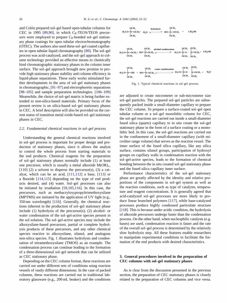
Understanding the general chemical reactions involvedin sol–gel process is important for proper design and pro-duction of stationary phases, since it allows the analystto control the whole process from starting materials tothe end products. Chemical reagents for the preparationof sol–gel stationary phases normally include (1) at leastone precursor, which is usually a metal alkoxide M(OR)x,[110] (2) a solvent to disperse the precursor(s), (3) a cat-alyst, which can be an acid,[111,112] a base,[113] ora fluoride [114,115] depending on the type of end prod-ucts desired, and (4) water. Sol–gel processes can alsobe initiated by irradiation[59,105,116]. In this case, theprecursors, such as methacryloxypropyltrimethoxysilane(MPTMS) are initiated by the application of UV light (e.g.,350 nm wavelength)[116]. Generally, the chemical reac-tions inherent in the production of sol–gel stationary phaseinclude (1) hydrolysis of the precursor(s); (2) alcohol- orwater condensation of the sol–gel-active species present inthe sol solution. The sol–gel-active species may include thealkoxysilane-based precursors, partial or complete hydrol-ysis products of these precursors, and any other chemicalspecies reactive to alkoxysilane, silanol, and analogousnon-silica species.Fig. 1 illustrates hydrolysis and conden-sation of tetramethoxysilane (TMOS) as an example. Thecondensation process can continue leading to the formationof a three-dimensional sol–gel network that can be utilizedas CEC stationary phase.
Depending on the CEC column format, these reactions arecarried out under different sets of conditions using reactionvessels of vastly different dimensions. In the case of packedcolumns, these reactions are carried out in traditional lab-oratory glassware (e.g., 200 mL beaker) and the conditions
Si OCH3H3CO
OCH3
OCH3
+ H2O
hydrolysisSi OCH3HO
OCH3
OCH3
CH3OH
Si OCH3H3COOCH3
OCH3
Si OCH3HO
OCH3
OCH3 alcohol condensationSi OH3CO
OCH3
OCH3
+
+ Si OCH3
OCH3
OCH3
+ CH3OH
Si OCH3HO
OCH3
OCH3
Si OHH3CO
OCH3
OCH3
+ Si OH3CO
OCH3
OCH3
Si OCH3
OCH3
OCH3
+ H2Owater condensation
Fig. 1. Typical chemical reactions in sol–gel process.
are adjusted to create micrometer or sub-micrometer sizesol–gel particles. The prepared sol–gel particles are subse-quently packed inside a small-diameter capillary to preparethe CEC column. To prepare a surface-coated sol–gel opentubular column or a sol–gel monolithic column for CEC,the sol–gel reactions are carried out inside a small-diameterfused silica (quartz) capillary to in situ create the sol–gelstationary phase in the form of a surface coating or a mono-lithic bed. In this case, the sol–gel reactions are carried outin the confinement of a small-diameter capillary (with mi-croliter range volume) that serves as the reaction vessel. Theinner surface of the fused silica capillary, like any silicasurface, contains silanol groups, participation of hydroxylgroups on capillary walls in condensation reaction with thesol–gel-active species, leads to the formation of chemicalbonding between the in situ created sol–gel stationary phaseand the fused silica capillary inner surface.
Performance characteristics of the sol–gel stationaryphase are greatly affected by the identity and relative pro-portions of the components in sol–gel system as well asthe reaction conditions, such as type of catalysts, tempera-ture and reagent concentrations. It is generally agreed thatacid-catalyzed sol–gel processes are more likely to pro-duce linear branched polymers [117], while base-catalyzedprocesses produce highly condensed particulate structure[118]. This is because under acidic condition, the hydrolysisof alkoxide precursors undergo faster than the condensationprocess. On the other hand, when nucleophilic catalysts (e.g.bases) are used, condensation reaction is faster and the rateof the overall sol–gel process is determined by the relativelyslow hydrolysis step. All these features enable researchersto manipulate experimental conditions to facilitate the for-mation of the end products with desired characteristics.
3. General procedures involved in the preparation ofCEC columns with sol–gel stationary phases
As is clear from the discussion presented in the previoussection, the preparation of CEC stationary phases is closelyrelated to the preparation of CEC columns and vice versa.
W. Li et al. / J. Chromatogr. A 1044 (2004) 23–52 27
Therefore, these two topics should be discussed in conjunc-tion with each other.
Several steps are involved in the preparation of CECcolumns with sol–gel stationary phases. The preparation pro-cedures vary depending on the types of the columns and theintended applications. They include pretreatment of the cap-illary, fabrication of the sol–gel stationary phases, and thepost-gelation treatment of the CEC stationary phases.
3.1. Pretreatment of the capillary
The purpose of capillary pretreatment is to increase theconcentration of surface silanol groups. Since silanol groupson the capillary surface represent the principal binding sitesfor in situ created sol–gel stationary phases, higher concen-tration of these binding sites on the capillary surface wouldfacilitate the formation of highly secured sol–gel stationaryphases through chemical bonding with the capillary innerwalls. Alkali solutions are used to clean the capillary surfacein addition of some organic solvents [89,90]. In the reportedone-step synthesis of monolithic silica column by Freitag’sgroup [119], the pretreatment of the bare fused silica wasaccomplished by flushing with 1 M NaOH, then, with 0.1 MHCl, and followed by rinsing with purified water. The simi-lar pretreatment method was used in other research groups toprepare sol–gel open-tubular [120] and monolithic columns[121–123]. Toyo’oka and co-workers [102,103,124] per-formed capillary pretreatment using methacryloxypropyl-trimethoxysilane (MPTMS) to form an anchor onto thesilicate matrix and prevent the gel from being leached outof the capillary. In Zare’s group [104,105], the pretreatmentprocedure was simplified by mere flushing the capillarywith a filling solution to wet the wall surface. No specialpretreatment was necessary for the bonding of photopoly-merized sol–gel monoliths on the wall. Hayes and Malik[100,101] reported the use of hydrothermal treatment of theinner surface of the fused silica capillary for the preparationof both sol–gel monolithic [100] and sol–gel open tubular[101] columns. The purpose of hydrothermal pretreatmentwas explained to be two-folds: cleaning the capillary innersurface and increasing the surface concentration of silanolgroups to effectively anchor the in situ created sol–gel sta-tionary phases, and it is also being used by other researchers[125,126].
3.2. Sol solution ingredients for the fabrication of thesol–gel stationary phases
The typical major components in the sol solution includeprecursor(s), a solvent system, a catalyst and water. How-ever, the actual operations for creating sol–gel stationaryphases involve the use of various additives to provide thedesired end products. In the sol solution, a porogen is oftenused, especially in creating a porous monolithic bed. Poro-gens play a dual role: they serve (a) as a thorough-pore tem-plate and (b) as a solubilizer of silane reagent. A porogen is
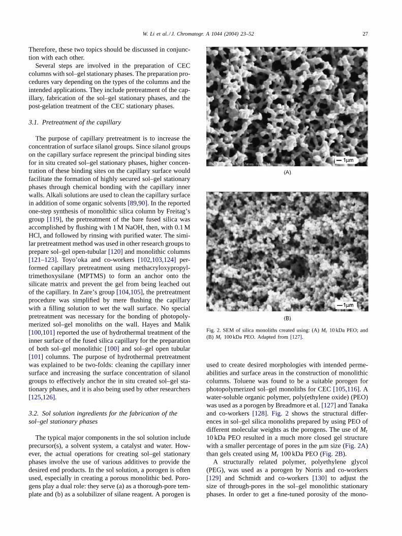
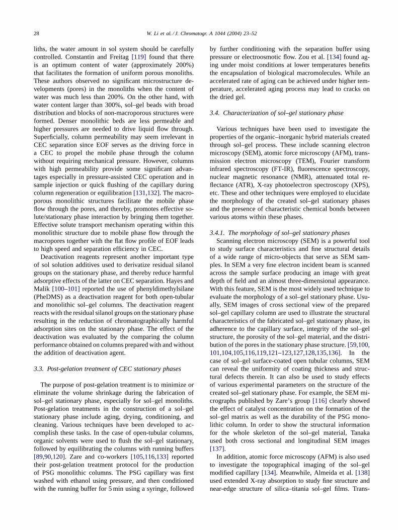
Fig. 2. SEM of silica monoliths created using: (A) Mr 10 kDa PEO; and(B) Mr 100 kDa PEO. Adapted from [127].
used to create desired morphologies with intended perme-abilities and surface areas in the construction of monolithiccolumns. Toluene was found to be a suitable porogen forphotopolymerized sol–gel monoliths for CEC [105,116]. Awater-soluble organic polymer, poly(ethylene oxide) (PEO)was used as a porogen by Breadmore et al. [127] and Tanakaand co-workers [128]. Fig. 2 shows the structural differ-ences in sol–gel silica monoliths prepared by using PEO ofdifferent molecular weights as the porogens. The use of Mr10 kDa PEO resulted in a much more closed gel structurewith a smaller percentage of pores in the �m size (Fig. 2A)than gels created using Mr 100 kDa PEO (Fig. 2B).
A structurally related polymer, polyethylene glycol(PEG), was used as a porogen by Norris and co-workers[129] and Schmidt and co-workers [130] to adjust thesize of through-pores in the sol–gel monolithic stationaryphases. In order to get a fine-tuned porosity of the mono-
28 W. Li et al. / J. Chromatogr. A 1044 (2004) 23–52
liths, the water amount in sol system should be carefullycontrolled. Constantin and Freitag [119] found that thereis an optimum content of water (approximately 200%)that facilitates the formation of uniform porous monoliths.These authors observed no significant microstructure de-velopments (pores) in the monoliths when the content ofwater was much less than 200%. On the other hand, withwater content larger than 300%, sol–gel beads with broaddistribution and blocks of non-macroporous structures wereformed. Denser monolithic beds are less permeable andhigher pressures are needed to drive liquid flow through.Superficially, column permeability may seem irrelevant inCEC separation since EOF serves as the driving force ina CEC to propel the mobile phase through the columnwithout requiring mechanical pressure. However, columnswith high permeability provide some significant advan-tages especially in pressure-assisted CEC operation and insample injection or quick flushing of the capillary duringcolumn regeneration or equilibration [131,132]. The macro-porous monolithic structures facilitate the mobile phaseflow through the pores, and thereby, promotes effective so-lute/stationary phase interaction by bringing them together.Effective solute transport mechanism operating within thismonolithic structure due to mobile phase flow through themacropores together with the flat flow profile of EOF leadsto high speed and separation efficiency in CEC.
Deactivation reagents represent another important typeof sol solution additives used to derivatize residual silanolgroups on the stationary phase, and thereby reduce harmfuladsorptive effects of the latter on CEC separation. Hayes andMalik [100–101] reported the use of phenyldimethylsilane(PheDMS) as a deactivation reagent for both open-tubularand monolithic sol–gel columns. The deactivation reagentreacts with the residual silanol groups on the stationary phaseresulting in the reduction of chromatographically harmfuladsorption sites on the stationary phase. The effect of thedeactivation was evaluated by the comparing the columnperformance obtained on columns prepared with and withoutthe addition of deactivation agent.
3.3. Post-gelation treatment of CEC stationary phases
The purpose of post-gelation treatment is to minimize oreliminate the volume shrinkage during the fabrication ofsol–gel stationary phase, especially for sol–gel monoliths.Post-gelation treatments in the construction of a sol–gelstationary phase include aging, drying, conditioning, andcleaning. Various techniques have been developed to ac-complish these tasks. In the case of open-tubular columns,organic solvents were used to flush the sol–gel stationary,followed by equilibrating the columns with running buffers[89,90,120]. Zare and co-workers [105,116,133] reportedtheir post-gelation treatment protocol for the productionof PSG monolithic columns. The PSG capillary was firstwashed with ethanol using pressure, and then conditionedwith the running buffer for 5 min using a syringe, followed
by further conditioning with the separation buffer usingpressure or electroosmotic flow. Zou et al. [134] found ag-ing under moist conditions at lower temperatures benefitsthe encapsulation of biological macromolecules. While anaccelerated rate of aging can be achieved under higher tem-perature, accelerated aging process may lead to cracks onthe dried gel.
3.4. Characterization of sol–gel stationary phase
Various techniques have been used to investigate theproperties of the organic–inorganic hybrid materials createdthrough sol–gel process. These include scanning electronmicroscopy (SEM), atomic force microscopy (AFM), trans-mission electron microscopy (TEM), Fourier transforminfrared spectroscopy (FT-IR), fluorescence spectroscopy,nuclear magnetic resonance (NMR), attenuated total re-flectance (ATR), X-ray photoelectron spectroscopy (XPS),etc. These and other techniques were employed to elucidatethe morphology of the created sol–gel stationary phasesand the presence of characteristic chemical bonds betweenvarious atoms within these phases.
3.4.1. The morphology of sol–gel stationary phasesScanning electron microscopy (SEM) is a powerful tool
to study surface characteristics and fine structural detailsof a wide range of micro-objects that serve as SEM sam-ples. In SEM a very fine electron incident beam is scannedacross the sample surface producing an image with greatdepth of field and an almost three-dimensional appearance.With this feature, SEM is the most widely used technique toevaluate the morphology of a sol–gel stationary phase. Usu-ally, SEM images of cross sectional view of the preparedsol–gel capillary column are used to illustrate the structuralcharacteristics of the fabricated sol–gel stationary phase, itsadherence to the capillary surface, integrity of the sol–gelstructure, the porosity of the sol–gel material, and the distri-bution of the pores in the stationary phase structure. [59,100,101,104,105,116,119,121–123,127,128,135,136]. In thecase of sol–gel surface-coated open tubular columns, SEMcan reveal the uniformity of coating thickness and struc-tural defects therein. It can also be used to study effectsof various experimental parameters on the structure of thecreated sol–gel stationary phase. For example, the SEM mi-crographs published by Zare’s group [116] clearly showedthe effect of catalyst concentration on the formation of thesol–gel matrix as well as the durability of the PSG mono-lithic column. In order to show the structural informationfor the whole skeleton of the sol–gel material, Tanakaused both cross sectional and longitudinal SEM images[137].
In addition, atomic force microscopy (AFM) is also usedto investigate the topographical imaging of the sol–gelmodified capillary [134]. Meanwhile, Almeida et al. [138]used extended X-ray absorption to study fine structure andnear-edge structure of silica–titania sol–gel films. Trans-
W. Li et al. / J. Chromatogr. A 1044 (2004) 23–52 29
mission electron microscopy (TEM) was used by Yan et al.[139] to characterize the magnesium silicate thin filmsobtained through sol–gel technique.
3.4.2. Study of the chemical bonds within sol–gel structureTo study the chemical bonds in sol–gel structure, vari-
ous techniques, such as Fourier transform infrared (FT-IR)[139–141], fluorescence [140] and nuclear magnetic reso-nance (NMR) [140,142–144] have been used. FT-IR is oneof the commonly used spectroscopic methods for study-ing polymers. Since spectra can be scanned, recorded, andtransformed in an extremely rapid pace, this technique en-ables the study of sol–gel process in its progression withtime. Toyo’oka and co-workers [145] used attenuated totalreflectance (ATR) FT-IR hybrid technique to monitor thecontent of residual silanol groups in sol–gel material as thegelation process progressed. Zuo et al. [134] used the FT-IRtechnique to confirm the encapsulation of bovine serum al-bumin (BSA) in the sol–gel matrix. IR technique was usedby Zeng and co-workers [146] to characterize the capillarymodified with macrocylic dioxopolyamine stationary phase.The typical IR absorptions of NH stretching (3303 cm−1),NH bending (1560 cm−1), C=O stretching (1652 cm−1),and CH stretching (2866–2933 cm−1) obtained from themodified capillaries provided the evidence for successfulpreparation of dioxo[13]aneN4—modified capillary foropen-tubular capillary electrochromatography.
To investigate the esterification reaction between stearicacid and the epoxy groups of glycidoxypropyltrimethoxysi-lane, Zhao et al. [120] used X-ray photoelectron spec-troscopy (XPS). The obtained XPS spectrum providedevidence on existence of carbon in the reaction productindicating to the success of the on-column octadecyl silyla-tion reaction. Consequently, the C18 group from the stearicacid, intended to act as the stationary phase, was confirmedto be chemically bonded to the sol–gel matrix.
Nuclear magnetic resonance (NMR), another powerfulanalytical technique, was used by Rodriguez and Colón[147] to investigate the species present in the sol–gel so-lution used to modify the inner surface of an open tubu-lar CEC column. It is established that in a sol–gel solutioncontaining more than one precursor, a homogenous hybridsystem is usually formed if the monomeric precursors un-dergo hydrolysis reactions at similar rates. However, if oneof the precursors has much faster rate for the hydrolysisreaction leading to pronounced self-condensation [148], aheterogeneous composite will be produced. Since the prop-erties of the final sol–gel columns can be indicated by thespecies present in the sol–gel solutions prior to the coatingprocess, it is very important to understand the characteris-tics of the sol–gel solution in details. The C18-TEOS/TEOSsol–gel system was studied by 29Si NMR [147]. The ac-quired spectra indicated the reactions of C18-TEOS were in-creased when reacting in the C18-TEOS/TEOS hybrid sys-tem, and the maximum degree condensation was achievedwithin 2 h.
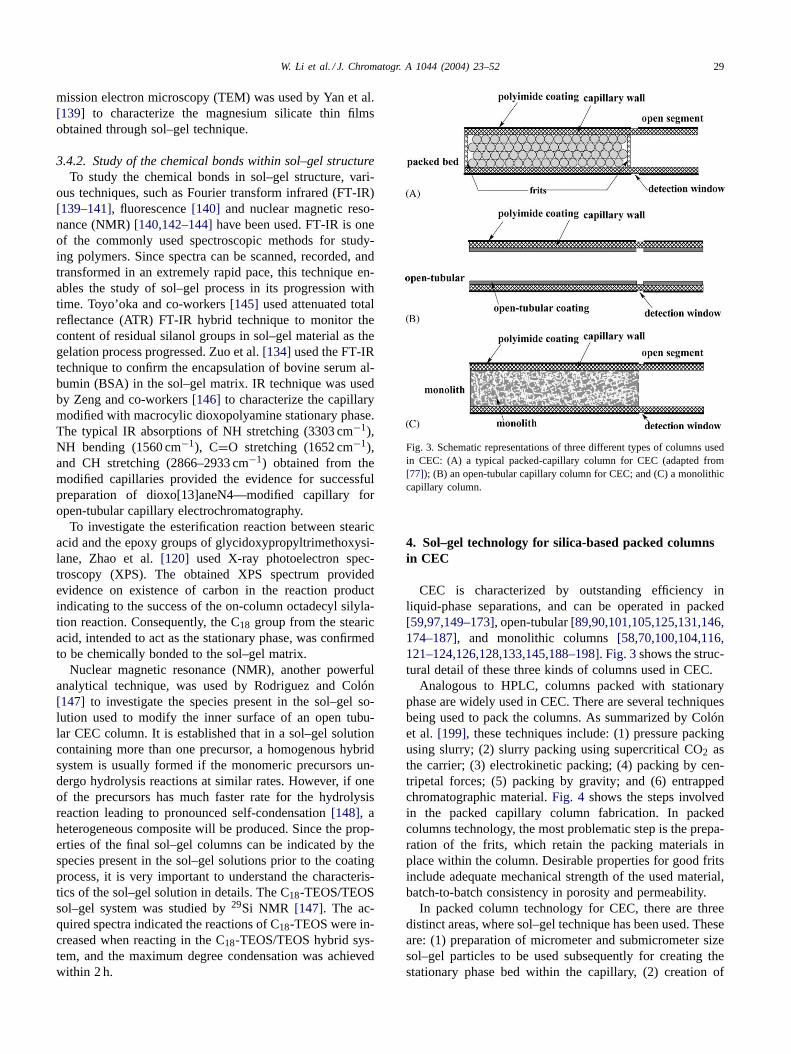
Fig. 3. Schematic representations of three different types of columns usedin CEC: (A) a typical packed-capillary column for CEC (adapted from[77]); (B) an open-tubular capillary column for CEC; and (C) a monolithiccapillary column.
4. Sol–gel technology for silica-based packed columnsin CEC
CEC is characterized by outstanding efficiency inliquid-phase separations, and can be operated in packed[59,97,149–173], open-tubular [89,90,101,105,125,131,146,174–187], and monolithic columns [58,70,100,104,116,121–124,126,128,133,145,188–198]. Fig. 3 shows the struc-tural detail of these three kinds of columns used in CEC.
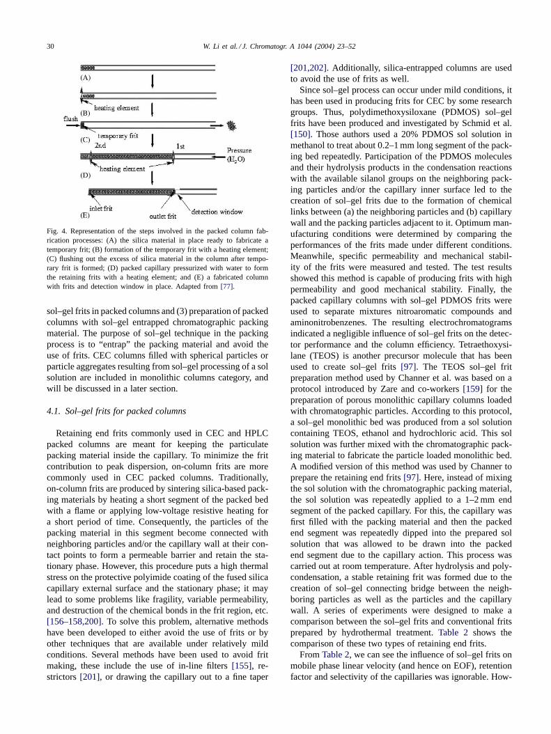
Analogous to HPLC, columns packed with stationaryphase are widely used in CEC. There are several techniquesbeing used to pack the columns. As summarized by Colónet al. [199], these techniques include: (1) pressure packingusing slurry; (2) slurry packing using supercritical CO2 asthe carrier; (3) electrokinetic packing; (4) packing by cen-tripetal forces; (5) packing by gravity; and (6) entrappedchromatographic material. Fig. 4 shows the steps involvedin the packed capillary column fabrication. In packedcolumns technology, the most problematic step is the prepa-ration of the frits, which retain the packing materials inplace within the column. Desirable properties for good fritsinclude adequate mechanical strength of the used material,batch-to-batch consistency in porosity and permeability.
In packed column technology for CEC, there are threedistinct areas, where sol–gel technique has been used. Theseare: (1) preparation of micrometer and submicrometer sizesol–gel particles to be used subsequently for creating thestationary phase bed within the capillary, (2) creation of
30 W. Li et al. / J. Chromatogr. A 1044 (2004) 23–52
Fig. 4. Representation of the steps involved in the packed column fab-rication processes: (A) the silica material in place ready to fabricate atemporary frit; (B) formation of the temporary frit with a heating element;(C) flushing out the excess of silica material in the column after tempo-rary frit is formed; (D) packed capillary pressurized with water to formthe retaining frits with a heating element; and (E) a fabricated columnwith frits and detection window in place. Adapted from [77].
sol–gel frits in packed columns and (3) preparation of packedcolumns with sol–gel entrapped chromatographic packingmaterial. The purpose of sol–gel technique in the packingprocess is to “entrap” the packing material and avoid theuse of frits. CEC columns filled with spherical particles orparticle aggregates resulting from sol–gel processing of a solsolution are included in monolithic columns category, andwill be discussed in a later section.
4.1. Sol–gel frits for packed columns
Retaining end frits commonly used in CEC and HPLCpacked columns are meant for keeping the particulatepacking material inside the capillary. To minimize the fritcontribution to peak dispersion, on-column frits are morecommonly used in CEC packed columns. Traditionally,on-column frits are produced by sintering silica-based pack-ing materials by heating a short segment of the packed bedwith a flame or applying low-voltage resistive heating fora short period of time. Consequently, the particles of thepacking material in this segment become connected withneighboring particles and/or the capillary wall at their con-tact points to form a permeable barrier and retain the sta-tionary phase. However, this procedure puts a high thermalstress on the protective polyimide coating of the fused silicacapillary external surface and the stationary phase; it maylead to some problems like fragility, variable permeability,and destruction of the chemical bonds in the frit region, etc.[156–158,200]. To solve this problem, alternative methodshave been developed to either avoid the use of frits or byother techniques that are available under relatively mildconditions. Several methods have been used to avoid fritmaking, these include the use of in-line filters [155], re-strictors [201], or drawing the capillary out to a fine taper
[201,202]. Additionally, silica-entrapped columns are usedto avoid the use of frits as well.
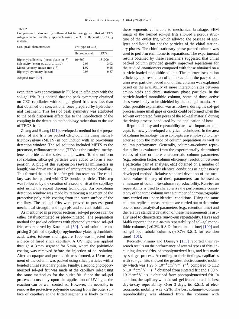
Since sol–gel process can occur under mild conditions, ithas been used in producing frits for CEC by some researchgroups. Thus, polydimethoxysiloxane (PDMOS) sol–gelfrits have been produced and investigated by Schmid et al.[150]. Those authors used a 20% PDMOS sol solution inmethanol to treat about 0.2–1 mm long segment of the pack-ing bed repeatedly. Participation of the PDMOS moleculesand their hydrolysis products in the condensation reactionswith the available silanol groups on the neighboring pack-ing particles and/or the capillary inner surface led to thecreation of sol–gel frits due to the formation of chemicallinks between (a) the neighboring particles and (b) capillarywall and the packing particles adjacent to it. Optimum man-ufacturing conditions were determined by comparing theperformances of the frits made under different conditions.Meanwhile, specific permeability and mechanical stabil-ity of the frits were measured and tested. The test resultsshowed this method is capable of producing frits with highpermeability and good mechanical stability. Finally, thepacked capillary columns with sol–gel PDMOS frits wereused to separate mixtures nitroaromatic compounds andaminonitrobenzenes. The resulting electrochromatogramsindicated a negligible influence of sol–gel frits on the detec-tor performance and the column efficiency. Tetraethoxysi-lane (TEOS) is another precursor molecule that has beenused to create sol–gel frits [97]. The TEOS sol–gel fritpreparation method used by Channer et al. was based on aprotocol introduced by Zare and co-workers [159] for thepreparation of porous monolithic capillary columns loadedwith chromatographic particles. According to this protocol,a sol–gel monolithic bed was produced from a sol solutioncontaining TEOS, ethanol and hydrochloric acid. This solsolution was further mixed with the chromatographic pack-ing material to fabricate the particle loaded monolithic bed.A modified version of this method was used by Channer toprepare the retaining end frits [97]. Here, instead of mixingthe sol solution with the chromatographic packing material,the sol solution was repeatedly applied to a 1–2 mm endsegment of the packed capillary. For this, the capillary wasfirst filled with the packing material and then the packedend segment was repeatedly dipped into the prepared solsolution that was allowed to be drawn into the packedend segment due to the capillary action. This process wascarried out at room temperature. After hydrolysis and poly-condensation, a stable retaining frit was formed due to thecreation of sol–gel connecting bridge between the neigh-boring particles as well as the particles and the capillarywall. A series of experiments were designed to make acomparison between the sol–gel frits and conventional fritsprepared by hydrothermal treatment. Table 2 shows thecomparison of these two types of retaining end frits.
From Table 2, we can see the influence of sol–gel frits onmobile phase linear velocity (and hence on EOF), retentionfactor and selectivity of the capillaries was ignorable. How-
W. Li et al. / J. Chromatogr. A 1044 (2004) 23–52 31
Table 2Comparison of standard hydrothermal frit technology with that of TEOSsol–gel/coupled capillary approach using the 3 �m Hypersil CEC C18
material
CEC peak characteristics Frit type (n = 3)
Hydrothermal TEOS
Biphenyl efficiency (mean plates m−1) 194600 181000Selectivity (mean αanisole/benzamide) 2.95 3.02Linear velocity (mean mm s−1) 1.02 0.96Biphenyl symmetry (mean) 0.98 0.87
Adapted from [97].
ever, there was approximately 7% loss in efficiency with thesol–gel frit. It is noticed that the peak symmetry obtainedon CEC capillaries with sol–gel glued frits was less thanthat obtained on conventional ones prepared by hydrother-mal treatment. This loss of peak symmetry was attributedto the peak dispersion effect due to the introduction of thecoupling in the detection methodology rather than to the useof TEOS frits.
Zhang and Huang [151] developed a method for the prepa-ration of end frits for packed CEC columns using methyl-triethoxysilane (METS) in conjunction with an on-columndetection window. The sol solution included METS as theprecursor, trifluoroacetic acid (TFA) as the catalyst, methy-lene chloride as the solvent, and water. To the uniformsol solution, silica gel particles were added to form a sus-pension. A plug of this suspension (several millimeters inlength) was drawn into a piece of empty pretreated capillary.This formed the outlet frit after gelation reaction. The capil-lary was then packed with ODS-bonded particles. This stepwas followed by the creation of a second frit at the capillaryinlet using the repeat dipping technology. An on-columndetection window was made by removing a segment of theprotective polyimide coating from the outer surface of thecapillary. The sol–gel frits were proved to possess goodmechanical strength, and high pH and solvent stabilities.
As mentioned in previous sections, sol–gel process can beeither catalyst-initiated or photo-initiated. The preparationmethod for packed columns with photopolymerized sol–gelfrits was reported by Kato et al. [59]. A sol solution com-prising 3-(trimethoxysilyl)propylmethacrylate, hydrochloricacid, water, toluene and Irgacure 1800 was injected intoa piece of fused silica capillary. A UV light was appliedthrough a 3 mm segment for 5 min, where the polyimidecoating was removed before the injection of sol solution.After an opaque and porous frit was formed, a 15 cm seg-ment of the column was packed using silica particles with abonded chiral stationary phase. Finally, a second photopoly-merized sol–gel frit was made at the capillary inlet usingthe same method as for the outlet frit. Since the sol–gelprocess occurs only upon the application of UV light, thereaction can be well controlled. However, the necessity toremove the protective polyimide coating from the outer sur-face of capillary at the fritted segments is likely to make
these segments vulnerable to mechanical breakage. SEMimage of the formed sol–gel frits showed a porous struc-ture of the outlet frit, which allowed the passage of ana-lytes and liquid but not the particles of the chiral station-ary phases. The chiral stationary phase packed column wasused to perform enantiomeric separations. The experimentalresults obtained by these researchers suggested that chiralpacked column provided greatly improved separations forthe studied enantiomers compared with those obtained on aparticle-loaded monolithic column. The improved separationefficiency and resolution of amino acids in the packed col-umn over particle-loaded monolithic column was explainedbased on the availability of more interaction sites betweenamino acids and chiral stationary phase particles. In theparticle-loaded monolithic column, some of those activesites were likely to be shielded by the sol–gel matrix. An-other possible explanation was as follows: during the sol–gelprocess, some small gaps or cracks could be formed when thesolvent evaporated from pores of the sol–gel material duringthe drying process conducted by the application of heat.
Reproducibility and repeatability are two important con-cepts for newly developed analytical techniques. In the areaof column technology, these concepts are employed to char-acterize both the method of column preparation as well ascolumn performance. Generally, column-to-column repro-ducibility is evaluated from the experimentally determinedvalues of one or more characteristic column parameters(e.g., retention factor, column efficiency, resolution betweena particular pair of analytes, etc.) obtained on a number ofcolumns prepared under identical conditions using the newlydeveloped method. Relative standard deviation of the mea-sured values for any of these parameters can be used asa measure of column-to-column reproducibility. Run-to-runrepeatability is used to characterize the performance consis-tency of the same column over a number of chromatographicruns carried out under identical conditions. Using the samecolumn, replicate measurements are carried out to determineone or more analytical parameters (e.g., retention time) andthe relative standard deviation of these measurements is usu-ally used to characterize run-to-run repeatability. Hayes andMalik reported the run-to-run repeatability of sol–gel mono-lithic columns (<0.3% R.S.D. for retention time) [100] andsol–gel open tubular columns (<0.7% R.S.D. for retentiontime) [101].
Recently, Piraino and Dorsey’s [153] reported their re-search results on the performance of several types of frits, in-cluding sintered frits, photopolymerized frits, and frits madeby sol–gel process. According to their findings, capillarieswith sol–gel frits showed the greatest electroosmotic mobil-ity which was 1.29 × 10⁻³ cm2 V−1 s−1, compared to 1.12× 10⁻³ cm2 V−1 s−1 obtained from sintered frit and 1.00 ×10⁻³ cm2 V−1 s−1 obtained from photopolymerized frit. Inaddition, the capillary with the sol–gel frit exhibited the bestday-to-day repeatability. Over 3 days, its R.S.D. of elec-troosmotic mobility was <2%. The best column-to-columnreproducibility was obtained from the columns with
32 W. Li et al. / J. Chromatogr. A 1044 (2004) 23–52
photopolymerized frits. The R.S.D. for all runs was <3%.However, its electroosmotic mobility was the slowest. Thesintered frits contributed to the least amount of band broad-ening. Euerby and co-workers [97] studied the repeatabilityand reproducibility of three different sol–gel related ap-proaches for frit production in terms of migration speed,retention time, retention factor, column efficiency and se-lectivity.
4.2. Packed columns with sol–gel entrapped stationaryphase particles
Since the use of frits is associated with a number ofproblems, including bubble formation during CEC opera-tion [154], column fragility [155], variable permeability andrelated shortcomings [156–158], attempts have been madeto find methods to prepare fritless packed columns. Packedcolumns with entrapped chromatographic materials makeit possible to avoid the use of frits. Sol–gel technologyhas been used to entrap the bonded stationary phase par-ticles inside the capillary. The methodology developed byZare’s research group [159] involved the preparation of asol–gel solution containing TEOS, ethanol, and hydrochlo-ric acid followed by addition of ODS particles to create asuspension. This suspension was then introduced into thecapillary by pressure. A microscope was used to ensure thata relatively uniform distribution of ODS particles occurredthroughout the column. Polymerization of the sol–gel ma-trix due to condensation reaction led to effective entrapmentof the particles within the sol–gel matrix. And the wholestructure was tightly fixed onto the wall of the capillary.Good electroosmotic flow was obtained through the packedcolumns with sol–gel-entrapped chromatographic station-ary phase. To evaluate the performance of the packed col-umn, a mixture of aromatic and non-aromatic compoundswere used. The sol–gel-entrapped packed column providedbaseline separation for all the test solutes. Efficiencies ofup to 80 000 plates/m were achieved in columns packedwith 3 �m ODS particles. This technique was used to pre-pare a sol–gel entrapped particle-loaded column for theenantiomeric separation of protein- and non-protein aminoacids [203]. Silica particles (5 �m) were modified with chi-ral selectors (S)-N-3,5-dinitrobenzoyl-1-naphthylglycine or(S)-N-3,5-dinitrophenylaminocarbonyl-valine, respectively.Enantiomeric separation was achieved using columns ob-tained by entrapping those particles within a fused silicacapillary using a sol solution. A similar strategy has beensuccessfully used by Ratnayake et al. [160,204] to prepareparticle loaded sol–gel monolithic columns for CEC. It wasfurther demonstrated that this method to entrap chromato-graphic material inside the capillary without the use of fritswas suitable for CEC.
Another approach to produce packed columns with en-trapped chromatographic materials by sol–gel technologywas introduced by Tang et al. [161], who described a methodthat differed from that developed by Zare [159] in that the
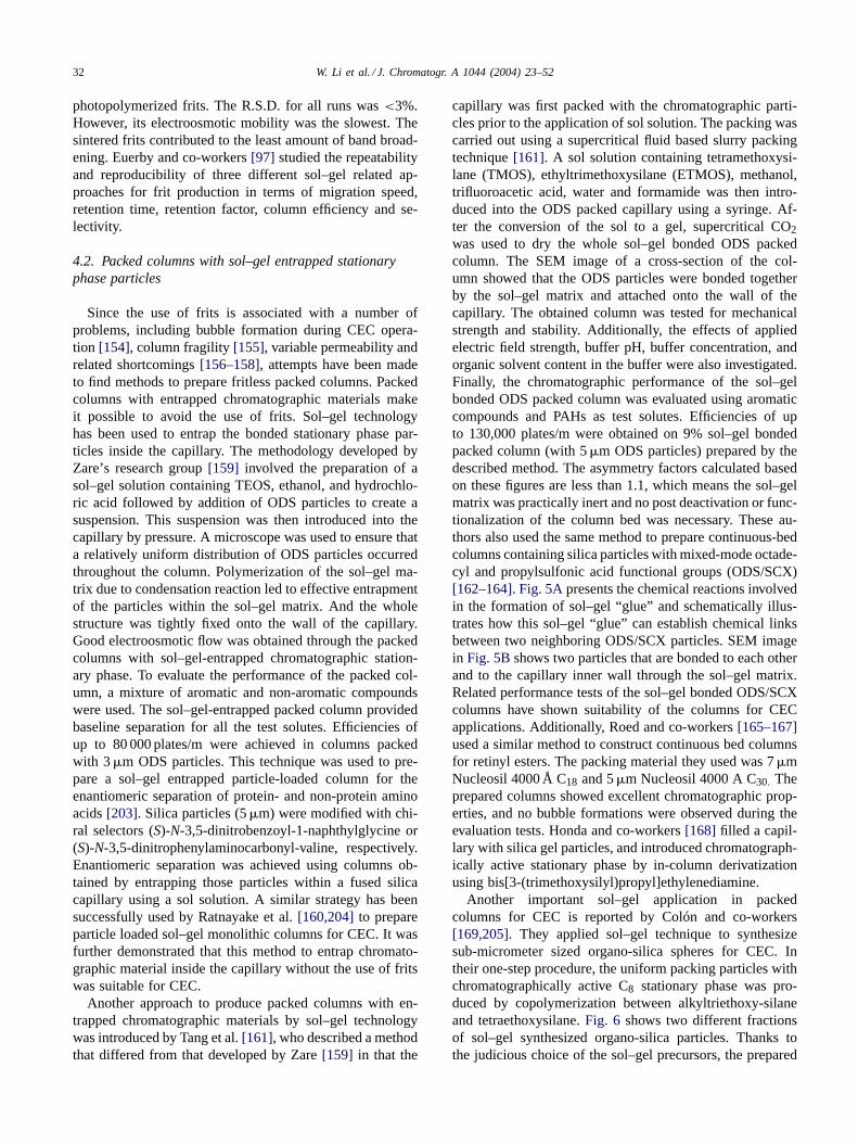
capillary was first packed with the chromatographic parti-cles prior to the application of sol solution. The packing wascarried out using a supercritical fluid based slurry packingtechnique [161]. A sol solution containing tetramethoxysi-lane (TMOS), ethyltrimethoxysilane (ETMOS), methanol,trifluoroacetic acid, water and formamide was then intro-duced into the ODS packed capillary using a syringe. Af-ter the conversion of the sol to a gel, supercritical CO2was used to dry the whole sol–gel bonded ODS packedcolumn. The SEM image of a cross-section of the col-umn showed that the ODS particles were bonded togetherby the sol–gel matrix and attached onto the wall of thecapillary. The obtained column was tested for mechanicalstrength and stability. Additionally, the effects of appliedelectric field strength, buffer pH, buffer concentration, andorganic solvent content in the buffer were also investigated.Finally, the chromatographic performance of the sol–gelbonded ODS packed column was evaluated using aromaticcompounds and PAHs as test solutes. Efficiencies of upto 130,000 plates/m were obtained on 9% sol–gel bondedpacked column (with 5 �m ODS particles) prepared by thedescribed method. The asymmetry factors calculated basedon these figures are less than 1.1, which means the sol–gelmatrix was practically inert and no post deactivation or func-tionalization of the column bed was necessary. These au-thors also used the same method to prepare continuous-bedcolumns containing silica particles with mixed-mode octade-cyl and propylsulfonic acid functional groups (ODS/SCX)[162–164]. Fig. 5A presents the chemical reactions involvedin the formation of sol–gel “glue” and schematically illus-trates how this sol–gel “glue” can establish chemical linksbetween two neighboring ODS/SCX particles. SEM imagein Fig. 5B shows two particles that are bonded to each otherand to the capillary inner wall through the sol–gel matrix.Related performance tests of the sol–gel bonded ODS/SCXcolumns have shown suitability of the columns for CECapplications. Additionally, Roed and co-workers [165–167]used a similar method to construct continuous bed columnsfor retinyl esters. The packing material they used was 7 �mNucleosil 4000 Å C18 and 5 �m Nucleosil 4000 A C30. Theprepared columns showed excellent chromatographic prop-erties, and no bubble formations were observed during theevaluation tests. Honda and co-workers [168] filled a capil-lary with silica gel particles, and introduced chromatograph-ically active stationary phase by in-column derivatizationusing bis[3-(trimethoxysilyl)propyl]ethylenediamine.
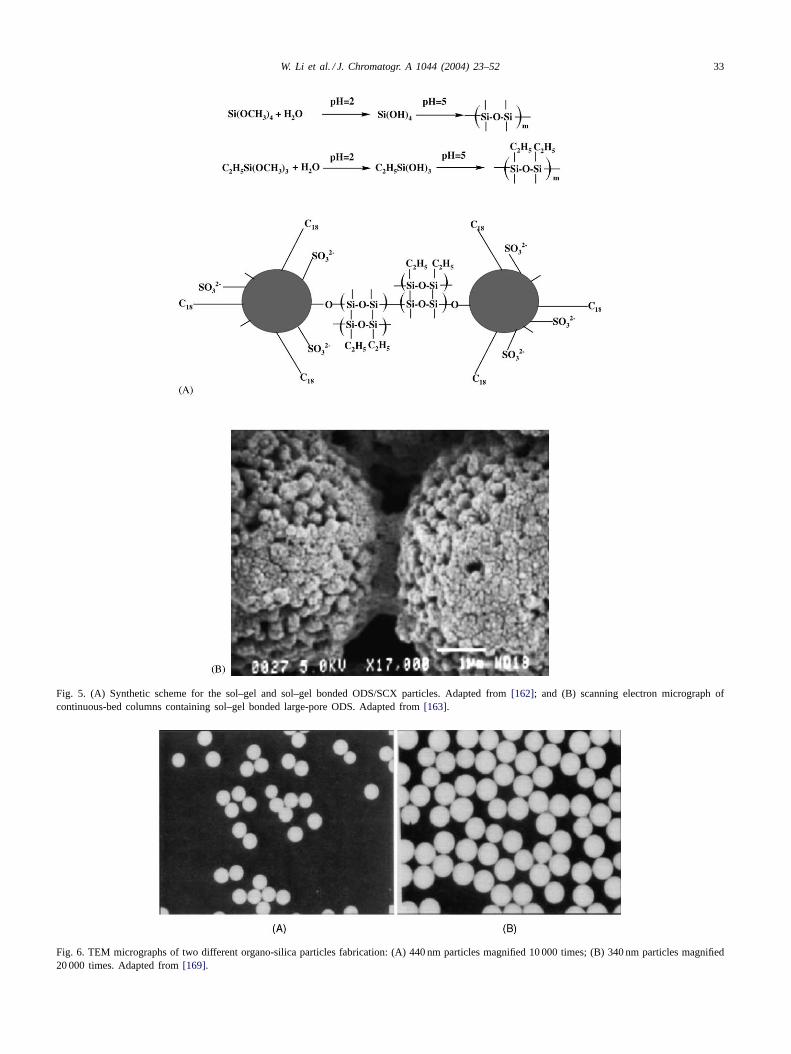
Another important sol–gel application in packedcolumns for CEC is reported by Colón and co-workers[169,205]. They applied sol–gel technique to synthesizesub-micrometer sized organo-silica spheres for CEC. Intheir one-step procedure, the uniform packing particles withchromatographically active C8 stationary phase was pro-duced by copolymerization between alkyltriethoxy-silaneand tetraethoxysilane. Fig. 6 shows two different fractionsof sol–gel synthesized organo-silica particles. Thanks tothe judicious choice of the sol–gel precursors, the prepared
W. Li et al. / J. Chromatogr. A 1044 (2004) 23–52 33
Fig. 5. (A) Synthetic scheme for the sol–gel and sol–gel bonded ODS/SCX particles. Adapted from [162]; and (B) scanning electron micrograph ofcontinuous-bed columns containing sol–gel bonded large-pore ODS. Adapted from [163].
Fig. 6. TEM micrographs of two different organo-silica particles fabrication: (A) 440 nm particles magnified 10 000 times; (B) 340 nm particles magnified20 000 times. Adapted from [169].
34 W. Li et al. / J. Chromatogr. A 1044 (2004) 23–52
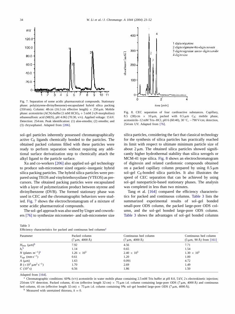
Fig. 7. Separation of some acidic pharmaceutical compounds. Stationaryphase: poly(styrene-divinylbenzene)-encapsulated hybrid silica packing(350 nm). Column: 48 cm (16.5 cm effective length) × 250 �m. Mobilephase: acetonitrite (ACN)-buffer [1 mM HClO4 + 5 mM 2-(N-morpholino)ethanesulfonic acid (MES), pH 4.06] (70:30, v/v). Applied voltage: 15 kV.Detection: 254 nm. Peak identification: (1) aloe-emodin; (2) emodin; and(3) chrysophanol. Adapted from [206].
sol–gel particles inherently possessed chromatographicallyactive C8 ligands chemically bonded to the particles. Theobtained packed columns filled with these particles wereready to perform separation without requiring any addi-tional surface derivatization step to chemically attach thealkyl ligand to the particle surface.
Xu and co-workers [206] also applied sol–gel technologyto produce sub-micrometer sized organic–inorganic hybridsilica packing particles. The hybrid silica particles were pre-pared using TEOS and vinyltriethoxysilane (VTEOS) as pre-cursors. The obtained packing particles were encapsulatedwith a layer of polymerization product between styrene anddivinylbenzene (DVB). The formed stationary phase wasused in CEC and the chromatographic behaviors were stud-ied. Fig. 7 shows the electrochromatogram of a mixture ofsome acidic pharmaceutical compounds.
The sol–gel approach was also used by Unger and cowork-ers [76] to synthesize micrometer- and sub-micrometer size
Table 3Efficiency characteristics for packed and continuous bed columnsa
Parameter Packed column(7 �m, 4000 Å)
Continuous bed column(7 �m, 4000 Å)
Continuous bed column(5 �m, 90 Å) from [161]
Hmin (�m)b 7.92 4.56 7.71hr
b 1.14 0.65 1.54N (plates m−1)b 1.26 × 10⁵ 2.40 × 10⁵ 1.30 × 10⁵
Vopt (mm s−1) 0.61 1.20 1.00A (�m) 1.63 0.091 4.72B (×103 �m2 s−1) 1.70 2.69 1.49C (103 s) 6.56 1.86 1.50
Adapted from [164].a Chromatographic conditions: 60% (v/v) acetonitrile in water mobile phase containing 2.5 mM Tris buffer at pH 8.0, 5 kV, 2 s electrokinetic injection;
254 nm UV detection. Packed column, 41 cm (effective length 32 cm) × 75 �m i.d. column containing large-pore ODS (7 �m, 4000 Å) and continuousbed column, 41 cm (effective length 32 cm) × 75 �m i.d. column containing 9% sol–gel bonded large-pore ODS (7 �m, 4000 Å).
b Measured with unretained thioruea, k = 0.
Fig. 8. CEC separation of four cardioactive substances. Capillary,8.5 (38) cm × 10 �m, packed with 0.5 �m C8; mobile phase,acetonitrile–12 mM Tris–HCl, pH 6 (60:40), 30 ◦C, −790 V/cm; detection,254 nm UV. Adapted from [76].
silica particles, considering the fact that classical technologyfor the synthesis of silica particles has practically reachedits limit with respect to ultimate minimum particle size ofabout 2 �m. The obtained silica particles showed signifi-cantly higher hydrothermal stability than silica xerogels orMCM-41 type silica. Fig. 8 shows an electrochromatogramof digitoxin and related cardiotonic compounds obtainedon a packed capillary column prepared by using 0.5 �msol–gel C8-bonded silica particles. It also illustrates thespeed of CEC separation that can be achieved by usingsol–gel nanoparticle-based stationary phases. The analysiswas completed in less than two minutes.
Tang et al. [164] compared the efficiency characteris-tics for packed and continuous columns. Table 3 lists thesummarized experimental results of sol–gel bondedsmall-pore ODS column, the packed large-pore ODS col-umn, and the sol–gel bonded large-pore ODS column.Table 3 shows the advantages of sol–gel bonded columns
W. Li et al. / J. Chromatogr. A 1044 (2004) 23–52 35
over packed column in terms of efficiency, EOF, and masstransfer.
5. Open-tubular CEC columns with silica-based sol–gelcoatings
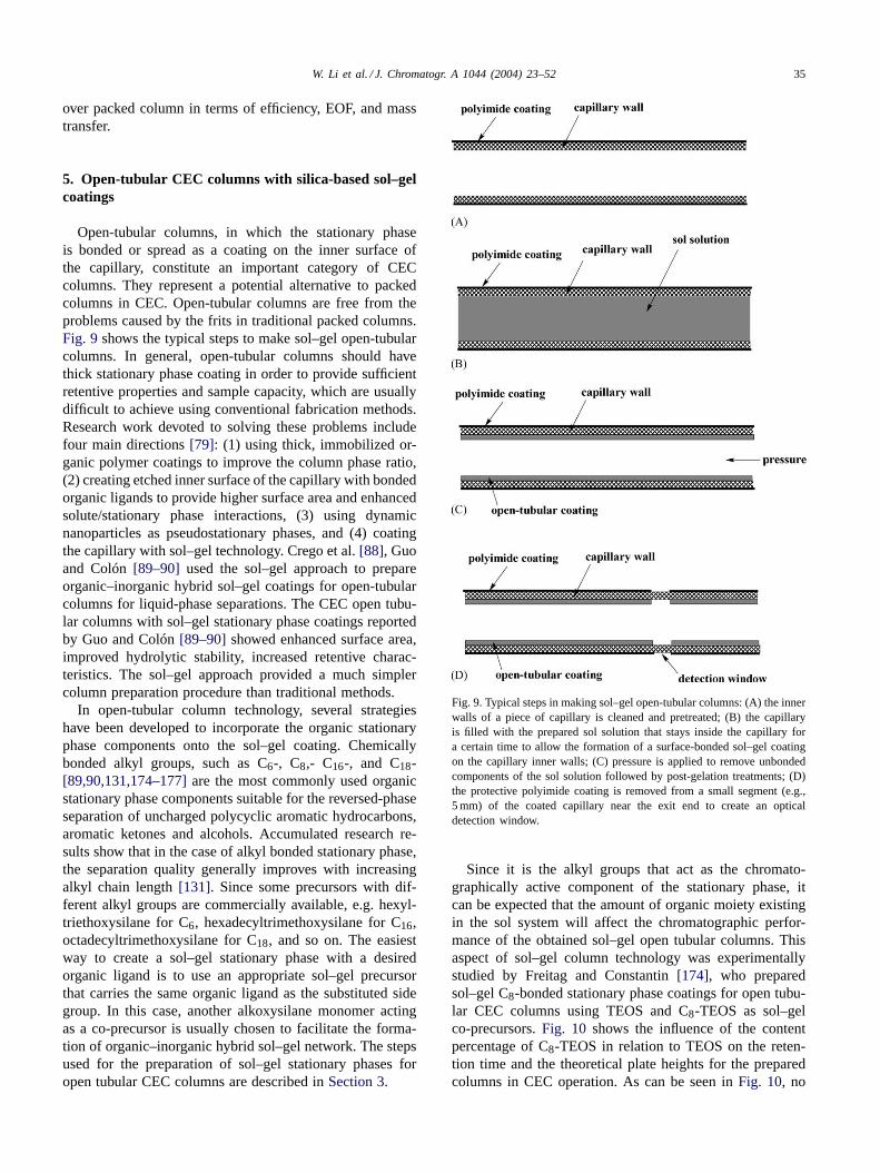
Open-tubular columns, in which the stationary phaseis bonded or spread as a coating on the inner surface ofthe capillary, constitute an important category of CECcolumns. They represent a potential alternative to packedcolumns in CEC. Open-tubular columns are free from theproblems caused by the frits in traditional packed columns.Fig. 9 shows the typical steps to make sol–gel open-tubularcolumns. In general, open-tubular columns should havethick stationary phase coating in order to provide sufficientretentive properties and sample capacity, which are usuallydifficult to achieve using conventional fabrication methods.Research work devoted to solving these problems includefour main directions [79]: (1) using thick, immobilized or-ganic polymer coatings to improve the column phase ratio,(2) creating etched inner surface of the capillary with bondedorganic ligands to provide higher surface area and enhancedsolute/stationary phase interactions, (3) using dynamicnanoparticles as pseudostationary phases, and (4) coatingthe capillary with sol–gel technology. Crego et al. [88], Guoand Colón [89–90] used the sol–gel approach to prepareorganic–inorganic hybrid sol–gel coatings for open-tubularcolumns for liquid-phase separations. The CEC open tubu-lar columns with sol–gel stationary phase coatings reportedby Guo and Colón [89–90] showed enhanced surface area,improved hydrolytic stability, increased retentive charac-teristics. The sol–gel approach provided a much simplercolumn preparation procedure than traditional methods.
In open-tubular column technology, several strategieshave been developed to incorporate the organic stationaryphase components onto the sol–gel coating. Chemicallybonded alkyl groups, such as C6-, C8,- C16-, and C18-[89,90,131,174–177] are the most commonly used organicstationary phase components suitable for the reversed-phaseseparation of uncharged polycyclic aromatic hydrocarbons,aromatic ketones and alcohols. Accumulated research re-sults show that in the case of alkyl bonded stationary phase,the separation quality generally improves with increasingalkyl chain length [131]. Since some precursors with dif-ferent alkyl groups are commercially available, e.g. hexyl-triethoxysilane for C6, hexadecyltrimethoxysilane for C16,octadecyltrimethoxysilane for C18, and so on. The easiestway to create a sol–gel stationary phase with a desiredorganic ligand is to use an appropriate sol–gel precursorthat carries the same organic ligand as the substituted sidegroup. In this case, another alkoxysilane monomer actingas a co-precursor is usually chosen to facilitate the forma-tion of organic–inorganic hybrid sol–gel network. The stepsused for the preparation of sol–gel stationary phases foropen tubular CEC columns are described in Section 3.
Fig. 9. Typical steps in making sol–gel open-tubular columns: (A) the innerwalls of a piece of capillary is cleaned and pretreated; (B) the capillaryis filled with the prepared sol solution that stays inside the capillary fora certain time to allow the formation of a surface-bonded sol–gel coatingon the capillary inner walls; (C) pressure is applied to remove unbondedcomponents of the sol solution followed by post-gelation treatments; (D)the protective polyimide coating is removed from a small segment (e.g.,5 mm) of the coated capillary near the exit end to create an opticaldetection window.
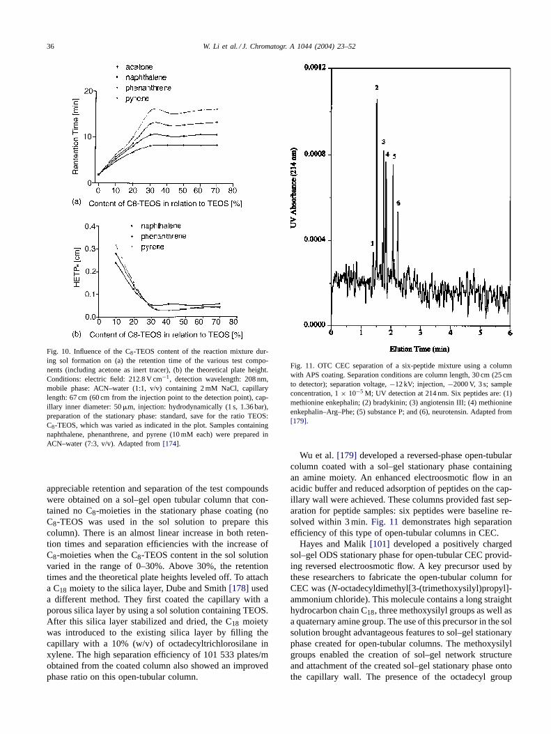
Since it is the alkyl groups that act as the chromato-graphically active component of the stationary phase, itcan be expected that the amount of organic moiety existingin the sol system will affect the chromatographic perfor-mance of the obtained sol–gel open tubular columns. Thisaspect of sol–gel column technology was experimentallystudied by Freitag and Constantin [174], who preparedsol–gel C8-bonded stationary phase coatings for open tubu-lar CEC columns using TEOS and C8-TEOS as sol–gelco-precursors. Fig. 10 shows the influence of the contentpercentage of C8-TEOS in relation to TEOS on the reten-tion time and the theoretical plate heights for the preparedcolumns in CEC operation. As can be seen in Fig. 10, no
36 W. Li et al. / J. Chromatogr. A 1044 (2004) 23–52
Fig. 10. Influence of the C8-TEOS content of the reaction mixture dur-ing sol formation on (a) the retention time of the various test compo-nents (including acetone as inert tracer), (b) the theoretical plate height.Conditions: electric field: 212.8 V cm−1, detection wavelength: 208 nm,mobile phase: ACN–water (1:1, v/v) containing 2 mM NaCl, capillarylength: 67 cm (60 cm from the injection point to the detection point), cap-illary inner diameter: 50 �m, injection: hydrodynamically (1 s, 1.36 bar),preparation of the stationary phase: standard, save for the ratio TEOS:C8-TEOS, which was varied as indicated in the plot. Samples containingnaphthalene, phenanthrene, and pyrene (10 mM each) were prepared inACN–water (7:3, v/v). Adapted from [174].
appreciable retention and separation of the test compoundswere obtained on a sol–gel open tubular column that con-tained no C8-moieties in the stationary phase coating (noC8-TEOS was used in the sol solution to prepare thiscolumn). There is an almost linear increase in both reten-tion times and separation efficiencies with the increase ofC8-moieties when the C8-TEOS content in the sol solutionvaried in the range of 0–30%. Above 30%, the retentiontimes and the theoretical plate heights leveled off. To attacha C18 moiety to the silica layer, Dube and Smith [178] useda different method. They first coated the capillary with aporous silica layer by using a sol solution containing TEOS.After this silica layer stabilized and dried, the C18 moietywas introduced to the existing silica layer by filling thecapillary with a 10% (w/v) of octadecyltrichlorosilane inxylene. The high separation efficiency of 101 533 plates/mobtained from the coated column also showed an improvedphase ratio on this open-tubular column.
Fig. 11. OTC CEC separation of a six-peptide mixture using a columnwith APS coating. Separation conditions are column length, 30 cm (25 cmto detector); separation voltage, −12 kV; injection, −2000 V, 3 s; sampleconcentration, 1 × 10⁻⁵ M; UV detection at 214 nm. Six peptides are: (1)methionine enkephalin; (2) bradykinin; (3) angiotensin III; (4) methionineenkephalin–Arg–Phe; (5) substance P; and (6), neurotensin. Adapted from[179].
Wu et al. [179] developed a reversed-phase open-tubularcolumn coated with a sol–gel stationary phase containingan amine moiety. An enhanced electroosmotic flow in anacidic buffer and reduced adsorption of peptides on the cap-illary wall were achieved. These columns provided fast sep-aration for peptide samples: six peptides were baseline re-solved within 3 min. Fig. 11 demonstrates high separationefficiency of this type of open-tubular columns in CEC.
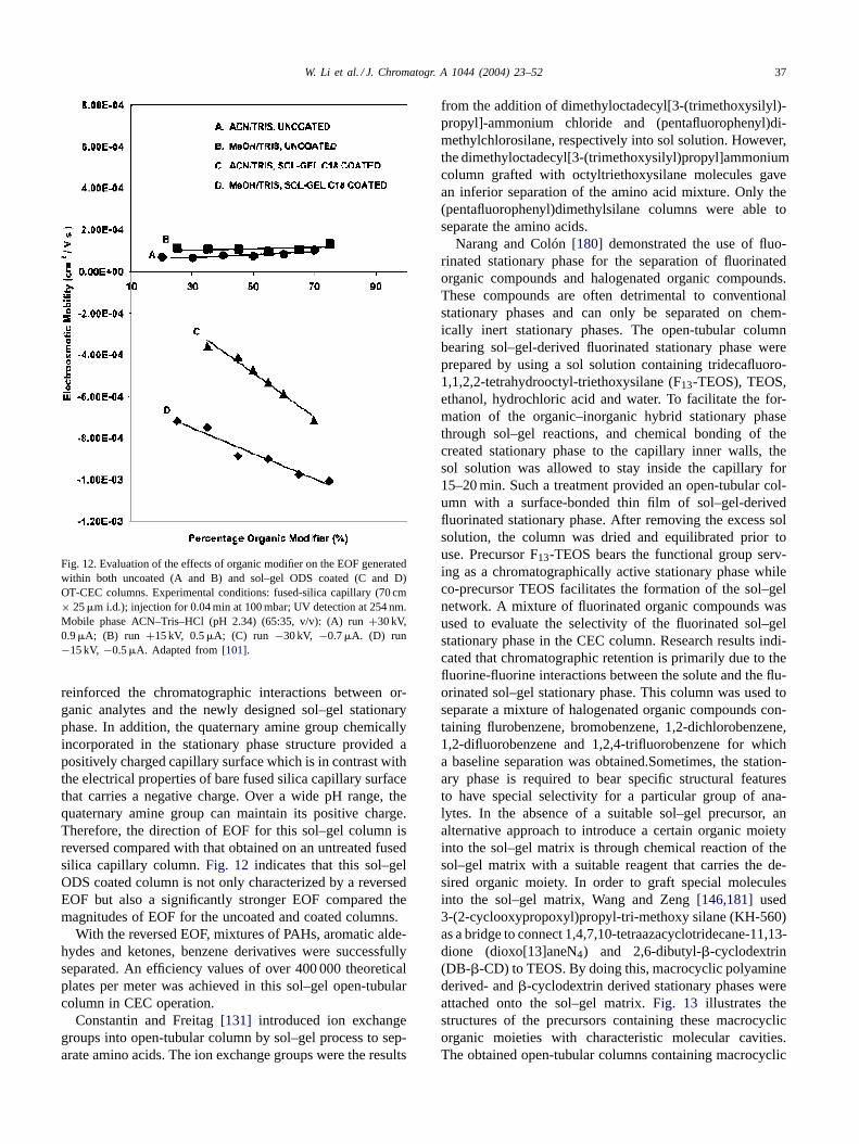
Hayes and Malik [101] developed a positively chargedsol–gel ODS stationary phase for open-tubular CEC provid-ing reversed electroosmotic flow. A key precursor used bythese researchers to fabricate the open-tubular column forCEC was (N-octadecyldimethyl[3-(trimethoxysilyl)propyl]-ammonium chloride). This molecule contains a long straighthydrocarbon chain C18, three methoxysilyl groups as well asa quaternary amine group. The use of this precursor in the solsolution brought advantageous features to sol–gel stationaryphase created for open-tubular columns. The methoxysilylgroups enabled the creation of sol–gel network structureand attachment of the created sol–gel stationary phase ontothe capillary wall. The presence of the octadecyl group
W. Li et al. / J. Chromatogr. A 1044 (2004) 23–52 37
Fig. 12. Evaluation of the effects of organic modifier on the EOF generatedwithin both uncoated (A and B) and sol–gel ODS coated (C and D)OT-CEC columns. Experimental conditions: fused-silica capillary (70 cm× 25 �m i.d.); injection for 0.04 min at 100 mbar; UV detection at 254 nm.Mobile phase ACN–Tris–HCl (pH 2.34) (65:35, v/v): (A) run +30 kV,0.9 �A; (B) run +15 kV, 0.5 �A; (C) run −30 kV, −0.7 �A. (D) run−15 kV, −0.5 �A. Adapted from [101].
reinforced the chromatographic interactions between or-ganic analytes and the newly designed sol–gel stationaryphase. In addition, the quaternary amine group chemicallyincorporated in the stationary phase structure provided apositively charged capillary surface which is in contrast withthe electrical properties of bare fused silica capillary surfacethat carries a negative charge. Over a wide pH range, thequaternary amine group can maintain its positive charge.Therefore, the direction of EOF for this sol–gel column isreversed compared with that obtained on an untreated fusedsilica capillary column. Fig. 12 indicates that this sol–gelODS coated column is not only characterized by a reversedEOF but also a significantly stronger EOF compared themagnitudes of EOF for the uncoated and coated columns.
With the reversed EOF, mixtures of PAHs, aromatic alde-hydes and ketones, benzene derivatives were successfullyseparated. An efficiency values of over 400 000 theoreticalplates per meter was achieved in this sol–gel open-tubularcolumn in CEC operation.
Constantin and Freitag [131] introduced ion exchangegroups into open-tubular column by sol–gel process to sep-arate amino acids. The ion exchange groups were the results
from the addition of dimethyloctadecyl[3-(trimethoxysilyl)-propyl]-ammonium chloride and (pentafluorophenyl)di-methylchlorosilane, respectively into sol solution. However,the dimethyloctadecyl[3-(trimethoxysilyl)propyl]ammoniumcolumn grafted with octyltriethoxysilane molecules gavean inferior separation of the amino acid mixture. Only the(pentafluorophenyl)dimethylsilane columns were able toseparate the amino acids.
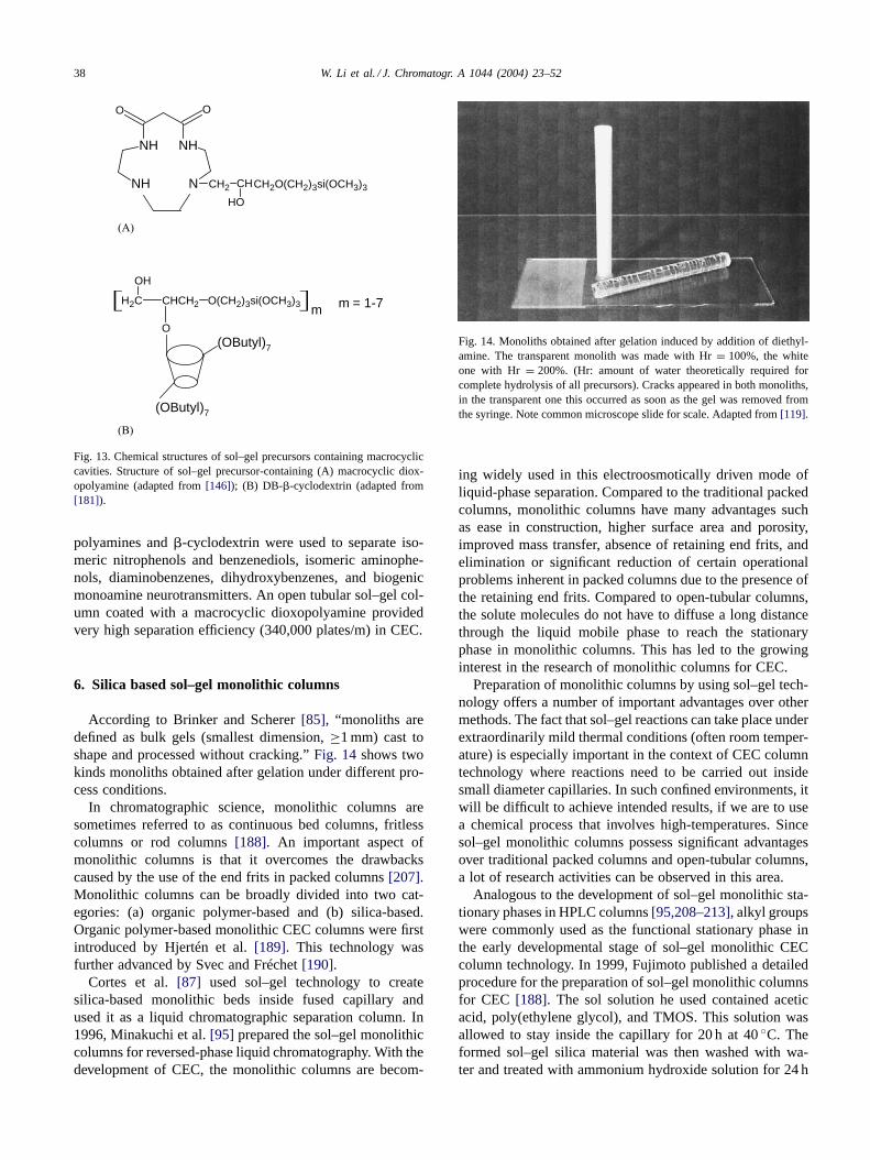
Narang and Colón [180] demonstrated the use of fluo-rinated stationary phase for the separation of fluorinatedorganic compounds and halogenated organic compounds.These compounds are often detrimental to conventionalstationary phases and can only be separated on chem-ically inert stationary phases. The open-tubular columnbearing sol–gel-derived fluorinated stationary phase wereprepared by using a sol solution containing tridecafluoro-1,1,2,2-tetrahydrooctyl-triethoxysilane (F13-TEOS), TEOS,ethanol, hydrochloric acid and water. To facilitate the for-mation of the organic–inorganic hybrid stationary phasethrough sol–gel reactions, and chemical bonding of thecreated stationary phase to the capillary inner walls, thesol solution was allowed to stay inside the capillary for15–20 min. Such a treatment provided an open-tubular col-umn with a surface-bonded thin film of sol–gel-derivedfluorinated stationary phase. After removing the excess solsolution, the column was dried and equilibrated prior touse. Precursor F13-TEOS bears the functional group serv-ing as a chromatographically active stationary phase whileco-precursor TEOS facilitates the formation of the sol–gelnetwork. A mixture of fluorinated organic compounds wasused to evaluate the selectivity of the fluorinated sol–gelstationary phase in the CEC column. Research results indi-cated that chromatographic retention is primarily due to thefluorine-fluorine interactions between the solute and the flu-orinated sol–gel stationary phase. This column was used toseparate a mixture of halogenated organic compounds con-taining flurobenzene, bromobenzene, 1,2-dichlorobenzene,1,2-difluorobenzene and 1,2,4-trifluorobenzene for whicha baseline separation was obtained.Sometimes, the station-ary phase is required to bear specific structural featuresto have special selectivity for a particular group of ana-lytes. In the absence of a suitable sol–gel precursor, analternative approach to introduce a certain organic moietyinto the sol–gel matrix is through chemical reaction of thesol–gel matrix with a suitable reagent that carries the de-sired organic moiety. In order to graft special moleculesinto the sol–gel matrix, Wang and Zeng [146,181] used3-(2-cyclooxypropoxyl)propyl-tri-methoxy silane (KH-560)as a bridge to connect 1,4,7,10-tetraazacyclotridecane-11,13-dione (dioxo[13]aneN4) and 2,6-dibutyl-�-cyclodextrin(DB-�-CD) to TEOS. By doing this, macrocyclic polyaminederived- and �-cyclodextrin derived stationary phases wereattached onto the sol–gel matrix. Fig. 13 illustrates thestructures of the precursors containing these macrocyclicorganic moieties with characteristic molecular cavities.The obtained open-tubular columns containing macrocyclic
38 W. Li et al. / J. Chromatogr. A 1044 (2004) 23–52
N
NH
NH
NH
OO
CH2 CH
HO
CH2O(CH2)3si(OCH3)3
H2C CHCH2
OH
O(CH2)3si(OCH3)3
O(OButyl)7
(OButyl)7
m m = 1-7
(A)
(B)
Fig. 13. Chemical structures of sol–gel precursors containing macrocycliccavities. Structure of sol–gel precursor-containing (A) macrocyclic diox-opolyamine (adapted from [146]); (B) DB-�-cyclodextrin (adapted from[181]).
polyamines and �-cyclodextrin were used to separate iso-meric nitrophenols and benzenediols, isomeric aminophe-nols, diaminobenzenes, dihydroxybenzenes, and biogenicmonoamine neurotransmitters. An open tubular sol–gel col-umn coated with a macrocyclic dioxopolyamine providedvery high separation efficiency (340,000 plates/m) in CEC.
6. Silica based sol–gel monolithic columns
According to Brinker and Scherer [85], “monoliths aredefined as bulk gels (smallest dimension, ≥1 mm) cast toshape and processed without cracking.” Fig. 14 shows twokinds monoliths obtained after gelation under different pro-cess conditions.
In chromatographic science, monolithic columns aresometimes referred to as continuous bed columns, fritlesscolumns or rod columns [188]. An important aspect ofmonolithic columns is that it overcomes the drawbackscaused by the use of the end frits in packed columns [207].Monolithic columns can be broadly divided into two cat-egories: (a) organic polymer-based and (b) silica-based.Organic polymer-based monolithic CEC columns were firstintroduced by Hjertén et al. [189]. This technology wasfurther advanced by Svec and Fréchet [190].
Cortes et al. [87] used sol–gel technology to createsilica-based monolithic beds inside fused capillary andused it as a liquid chromatographic separation column. In1996, Minakuchi et al. [95] prepared the sol–gel monolithiccolumns for reversed-phase liquid chromatography. With thedevelopment of CEC, the monolithic columns are becom-
Fig. 14. Monoliths obtained after gelation induced by addition of diethyl-amine. The transparent monolith was made with Hr = 100%, the whiteone with Hr = 200%. (Hr: amount of water theoretically required forcomplete hydrolysis of all precursors). Cracks appeared in both monoliths,in the transparent one this occurred as soon as the gel was removed fromthe syringe. Note common microscope slide for scale. Adapted from [119].
ing widely used in this electroosmotically driven mode ofliquid-phase separation. Compared to the traditional packedcolumns, monolithic columns have many advantages suchas ease in construction, higher surface area and porosity,improved mass transfer, absence of retaining end frits, andelimination or significant reduction of certain operationalproblems inherent in packed columns due to the presence ofthe retaining end frits. Compared to open-tubular columns,the solute molecules do not have to diffuse a long distancethrough the liquid mobile phase to reach the stationaryphase in monolithic columns. This has led to the growinginterest in the research of monolithic columns for CEC.
Preparation of monolithic columns by using sol–gel tech-nology offers a number of important advantages over othermethods. The fact that sol–gel reactions can take place underextraordinarily mild thermal conditions (often room temper-ature) is especially important in the context of CEC columntechnology where reactions need to be carried out insidesmall diameter capillaries. In such confined environments, itwill be difficult to achieve intended results, if we are to usea chemical process that involves high-temperatures. Sincesol–gel monolithic columns possess significant advantagesover traditional packed columns and open-tubular columns,a lot of research activities can be observed in this area.
Analogous to the development of sol–gel monolithic sta-tionary phases in HPLC columns [95,208–213], alkyl groupswere commonly used as the functional stationary phase inthe early developmental stage of sol–gel monolithic CECcolumn technology. In 1999, Fujimoto published a detailedprocedure for the preparation of sol–gel monolithic columnsfor CEC [188]. The sol solution he used contained aceticacid, poly(ethylene glycol), and TMOS. This solution wasallowed to stay inside the capillary for 20 h at 40 ◦C. Theformed sol–gel silica material was then washed with wa-ter and treated with ammonium hydroxide solution for 24 h
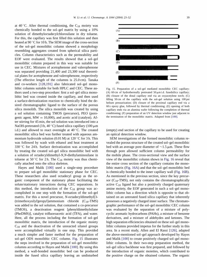
W. Li et al. / J. Chromatogr. A 1044 (2004) 23–52 39
at 40 ◦C. After thermal conditioning, the C18 moiety waschemically bonded to the sol–gel matrix by using a 10%solution of dimethyloctadecylchlorosilane in dry toluene.For this, the capillary was first filled this solution and thenheated at 90 ◦C for 10 h. The SEM image of the cross-sectionof the sol–gel monolithic column showed a morphologyresembling aggregates created from spherical silica parti-cles. Column characteristics such as the permeability andEOF were evaluated. The results showed that a sol–gelmonolithic column prepared in this way was suitable foruse in CEC. Mixtures of acetophenone and valerophenonewas separated providing 21,400 and 23,300 total theoreti-cal plates for acetophenone and valerophenone, respectively(The effective length of the columns is 25.0 cm). Tanakaand co-workers [128,191] also fabricated sol–gel mono-lithic columns suitable for both HPLC and CEC. These au-thors used a two-step procedure: first a sol–gel silica mono-lithic bed was created inside the capillary, and then useda surface-derivatization reaction to chemically bind the de-sired chromatographic ligand to the surface of the poroussilica monolith. The silica monolith was created by usinga sol solution containing TMOS (precursor), PEO (poro-genic agent, MW = 10,000), and acetic acid (catalyst). Af-ter stirring for 45 min, the sol solution was introduced into aNaOH-pretreated (3 h, 40 ◦C) fused silica capillary (100 �mi.d.) and allowed to react overnight at 40 ◦C. The createdmonolithic silica bed was further treated with aqueous am-monium hydroxide solution (0.01 M) at 120 ◦C for 3 h. Thiswas followed by wash with ethanol and heat treatment at330 ◦C for 24 h. Surface derivatization was accomplishedby treating the created sol–gel silica monolithic bed witha solution of octadecyldimethyl-N,N-diethylaminosilane intoluene at 50 ◦C for 2 h. The C18 moiety was thus chemi-cally attached onto the silica skeleton.
Hayes and Malik [100] used a single-step procedureto prepare sol–gel monolithic stationary phase for CEC.These researchers also used octadecyl group as the or-ganic component of the stationary phase facilitating thesolute/stationary interactions during CEC separations. Inthis method, the introduction of the C18 group was ac-complished in one step with the formation of the sol–gelmatrix. For this a novel precursor, N-octadecyldimethyl[3-(trimethoxysilyl)propyl]ammonium chloride (C18-TMS)was added to the sol solution, that contained a co-precursor(TMOS), a deactivation reagent [phenyldimethylsilane(PheDMS)], catalyst trifluoroacetic acid (TFA), and water.Here, all the process including the formation of sol–gelmonolithic matrix, the introduction of the organic moietyC18 and the deactivation of the unreacted silanol groupswere accomplished virtually in one step. This provideda much simpler and faster method for the preparation ofsol–gel ODS monolithic CEC column. Fig. 15 illustratesthe steps involved in the preparation of sol–gel monolithiccolumns according to Hayes and Malik [100]. By using thismethod, a wall-bonded monolithic bed can be producedinside the fused silica capillary leaving an undisturbed
Fig. 15. Preparation of a sol–gel mediated monolithic CEC capillary:(A) 60 cm of hydrothermally pretreated 50 �m i.d. fusedsilica capillary;(B) closure of the distal capillary end via an oxyacetylene torch; (C)filling 50 cm of the capillary with the sol–gel solution using 100 psihelium pressurization; (D) closure of the proximal capillary end via a60 s epoxy glue, followed by thermal conditioning; (E) opening of bothcapillary ends via an alumina wafer following the completion of thermalconditioning; (F) preparation of an UV detection window just adjacent tothe termination of the monolithic matrix. Adapted from [100].
(empty) end section of the capillary to be used for creatingan optical detection window.
SEM investigations of the formed monolithic column re-vealed the porous structure of the created sol–gel monolithicbed with an average pore diameter of ∼1.5 �m. These flowthrough pore allowed sufficient column permeability forthe mobile phase. The cross-sectional view and the surfaceview of the monolithic column shown in Fig. 16 reveal thatthe entire cross section of the capillary contains the mono-lithic matrix (Fig. 16A) and that the sol–gel monolithic bedis chemically bonded to the inner capillary wall (Fig. 16B).As mentioned in the previous section, since the key precur-sor (C18-TMS), not only contains the chromatographicallyactive C18 ligand but also a positively charged quaternaryamine moiety, the EOF generated in such a sol–gel mono-lithic column has a direction which is opposite to that ob-tained on an untreated fused silica capillary that inherentlypossesses a negatively charged inner surface. The chromato-graphic performance of the sol–gel monolithic CEC columnwas evaluated by the separation of a mixture of poly-cyclic aromatic hydrocarbons (PAHs), a mixture of benzenederivatives, and a mixture of aldehydes and ketones. Thehigh separation efficiencies obtained on these sol–gel mono-lithic columns provided impetus for the further study in thisarea. In a recent study, Allen and El Rassi [126], adaptedthe above-mentioned sol–gel approach developed by Hayesand Malik [100] to create positively charged sol–gel mono-lithic columns. In their two-step preparation method, thesol–gel silica backbone was first prepared, and followed bythe introduction of organic moieties, which contributed tothe positive charge on the obtained columns. The organic
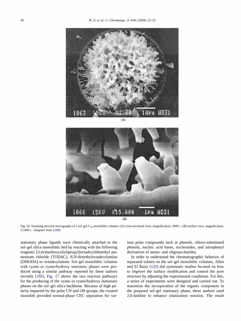
40 W. Li et al. / J. Chromatogr. A 1044 (2004) 23–52
Fig. 16. Scanning electron micrographs of a sol–gel C18 monolithic column: (A) cross-sectional view, magnification, 1800×; (B) surface view, magnification,15 000×. Adapted from [100].
stationary phase ligands were chemically attached to thesol–gel silica monolithic bed by reacting with the followingreagents: [3-(trimethoxysilyl)propyl]octadecyldimethyl am-monium chloride (TODAC), N,N-dimethyloctadecylamine(DMODA) or octadecylamine. Sol–gel monolithic columnswith cyano or cyano/hydroxy stationary phases were pro-duced using a similar pathway reported by these authorsrecently [192]. Fig. 17 shows the two reaction pathwaysfor the producing of the cyano or cyano/hydroxy stationaryphases on the sol–gel silica backbone. Because of high po-larity imparted by the polar CN and OH groups, the createdmonolith provided normal-phase CEC separation for var-
ious polar compounds such as phenols, chloro-substitutedphenols, nucleic acid bases, nucleosides, and nitrophenylderivatives of mono- and oligosaccharides.
In order to understand the chromatographic behavior ofseparated solutes on the sol–gel monolithic columns, Allenand El Rassi [125] did systematic studies focused on howto improve the surface modification and control the porestructure by adjusting the experimental conditions. For this,a series of experiments were designed and carried out. Tomaximize the incorporation of the organic component inthe prepared sol–gel stationary phase, these authors used2,6-lutidine to enhance silanization reaction. The result
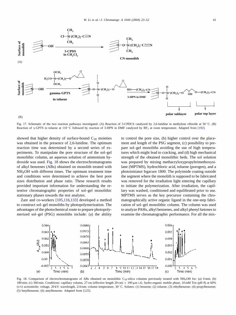
W. Li et al. / J. Chromatogr. A 1044 (2004) 23–52 41
Si O Si (CH2)3
CH3
CH3
C N
Cl Si (CH2)3
CH3
CH3
C N
Surf
ace
ofm
onol
ith Si OH
3-CPDS in CH2Cl2
Surf
ace
ofm
onol
ith
Si OH
CN-monolith
H3CO Si (CH2)3
OCH3
OCH3
O
O
Si O Si (CH2)3
O
O
O
O
Si O Si (CH2)3
O
O
O OHO (CH2)2 CN
3-HPN in DMF
OH (CH2)2 CN
polar sublayer polar top layer
gamma-GPTS
in toluene
(A)
(B)
Fig. 17. Schematic of the two reaction pathways investigated. (A) Reaction of 3-CPDCS catalyzed by 2,6-lutidine in methylene chloride at 50 ◦C. (B)Reaction of �-GPTS in toluene at 110 ◦C followed by reaction of 3-HPN in DMF catalyzed by BF3 at room temperature. Adapted from [192].
showed that higher density of surface-bound C18 moietieswas obtained in the presence of 2,6-lutidine. The optimumreaction time was determined by a second series of ex-periments. To manipulate the pore structure of the sol–gelmonolithic column, an aqueous solution of ammonium hy-droxide was used. Fig. 18 shows the electrochromatogramsof alkyl benzenes (ABs) obtained on monolith treated withNH4OH with different times. The optimum treatment timeand conditions were determined to achieve the best poresizes distribution and phase ratio. These research resultsprovided important information for understanding the re-tentive chromatographic properties of sol–gel monolithicstationary phases towards the test analytes.
Zare and co-workers [105,116,133] developed a methodto construct sol–gel monoliths by photopolymerization. Theadvantages of the photochemical route to prepare photopoly-merized sol–gel (PSG) monoliths include: (a) the ability
Fig. 18. Comparison of electrochromatograms of ABs obtained on monolithic C18-silica columns previously treated with NH4OH for: (a) 0 min; (b)180 min; (c) 360 min. Conditions: capillary column, 27 cm (effective length 20 cm) × 100 �m i.d.; hydro-organic mobile phase, 10 mM Tris (pH 8) at 60%(v/v) acetonitrile; voltage, 20 kV; wavelength, 214 nm; column temperature, 30 ◦C. Solutes: (1) benzene; (2) toluene; (3) ethylbenzene; (4) propylbenzene;(5) butylbenzene; (6) amylbenzene. Adapted from [125].
to control the pore size, (b) higher control over the place-ment and length of the PSG segment, (c) possibility to pre-pare sol–gel monoliths avoiding the use of high tempera-tures which might lead to cracking, and (d) high mechanicalstrength of the obtained monolithic beds. The sol solutionwas prepared by mixing methacryloxypropyltrimethoxysi-lane (MPTMS), hydrochloric acid, toluene (porogen), and aphotoinitiator Irgacure 1800. The polyimide coating outsidethe segment where the monolith is supposed to be fabricatedwas removed for the irradiation light entering the capillaryto initiate the polymerization. After irradiation, the capil-lary was washed, conditioned and equilibrated prior to use.MPTMS serves as the key precursor containing the chro-matographically active organic ligand in the one-step fabri-cation of sol–gel monolithic column. The column was usedto analyze PAHs, alkyl benzenes, and alkyl phenyl ketones toexamine the chromatographic performance. For all the mix-
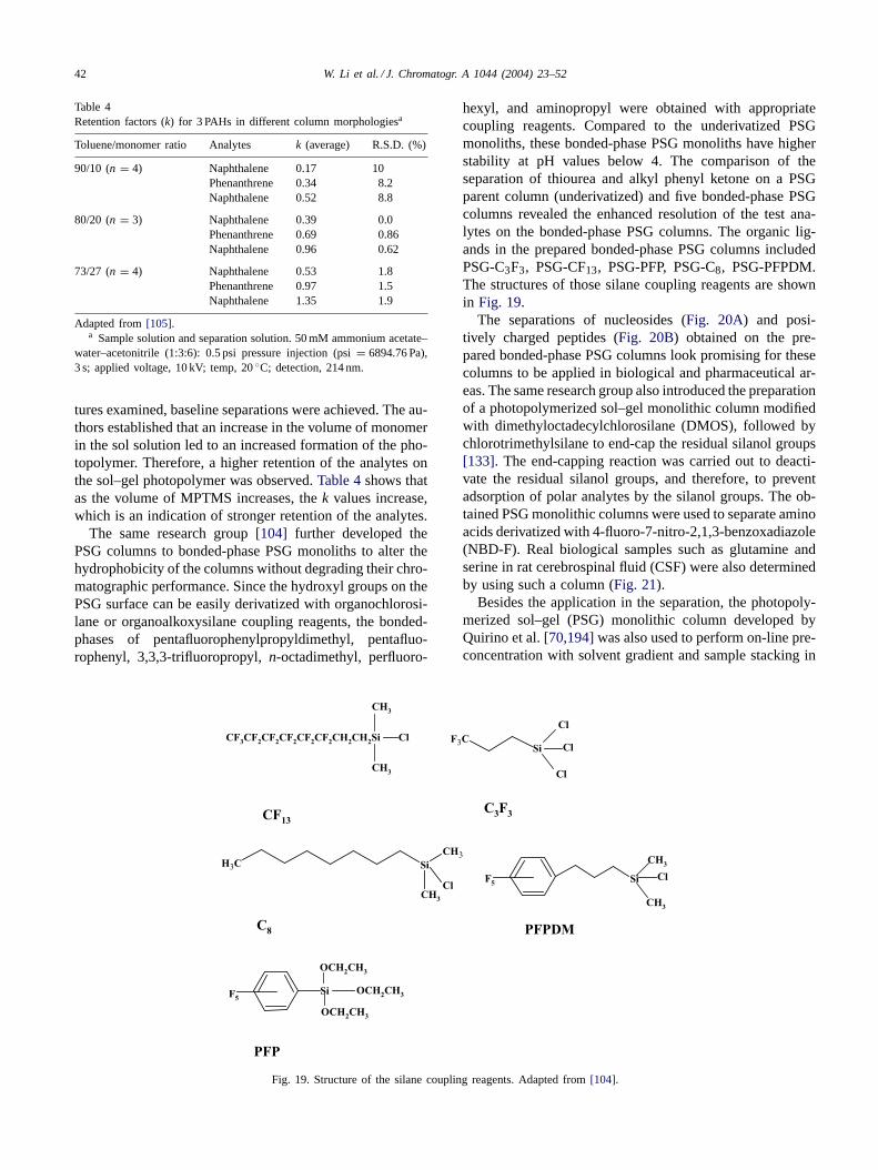
42 W. Li et al. / J. Chromatogr. A 1044 (2004) 23–52
Table 4Retention factors (k) for 3 PAHs in different column morphologiesa
Toluene/monomer ratio Analytes k (average) R.S.D. (%)
90/10 (n = 4) Naphthalene 0.17 10Phenanthrene 0.34 8.2Naphthalene 0.52 8.8
80/20 (n = 3) Naphthalene 0.39 0.0Phenanthrene 0.69 0.86Naphthalene 0.96 0.62
73/27 (n = 4) Naphthalene 0.53 1.8Phenanthrene 0.97 1.5Naphthalene 1.35 1.9
Adapted from [105].a Sample solution and separation solution. 50 mM ammonium acetate–
water–acetonitrile (1:3:6): 0.5 psi pressure injection (psi = 6894.76 Pa),3 s; applied voltage, 10 kV; temp, 20 ◦C; detection, 214 nm.
tures examined, baseline separations were achieved. The au-thors established that an increase in the volume of monomerin the sol solution led to an increased formation of the pho-topolymer. Therefore, a higher retention of the analytes onthe sol–gel photopolymer was observed. Table 4 shows thatas the volume of MPTMS increases, the k values increase,which is an indication of stronger retention of the analytes.
The same research group [104] further developed thePSG columns to bonded-phase PSG monoliths to alter thehydrophobicity of the columns without degrading their chro-matographic performance. Since the hydroxyl groups on thePSG surface can be easily derivatized with organochlorosi-lane or organoalkoxysilane coupling reagents, the bonded-phases of pentafluorophenylpropyldimethyl, pentafluo-rophenyl, 3,3,3-trifluoropropyl, n-octadimethyl, perfluoro-
CF3CF2CF2CF2CF2CF2CH2CH2Si
CH3
CH3
Cl F3CSi
Cl
Cl
Cl
CH3 SiCH3
ClCH3
Si
CH3
CH3
ClF5
F5Si
OCH2CH3
OCH2CH3
OCH2CH3
CF13C3F3
C8 PFPDM
PFP
Fig. 19. Structure of the silane coupling reagents. Adapted from [104].
hexyl, and aminopropyl were obtained with appropriatecoupling reagents. Compared to the underivatized PSGmonoliths, these bonded-phase PSG monoliths have higherstability at pH values below 4. The comparison of theseparation of thiourea and alkyl phenyl ketone on a PSGparent column (underivatized) and five bonded-phase PSGcolumns revealed the enhanced resolution of the test ana-lytes on the bonded-phase PSG columns. The organic lig-ands in the prepared bonded-phase PSG columns includedPSG-C3F3, PSG-CF13, PSG-PFP, PSG-C8, PSG-PFPDM.The structures of those silane coupling reagents are shownin Fig. 19.
The separations of nucleosides (Fig. 20A) and posi-tively charged peptides (Fig. 20B) obtained on the pre-pared bonded-phase PSG columns look promising for thesecolumns to be applied in biological and pharmaceutical ar-eas. The same research group also introduced the preparationof a photopolymerized sol–gel monolithic column modifiedwith dimethyloctadecylchlorosilane (DMOS), followed bychlorotrimethylsilane to end-cap the residual silanol groups[133]. The end-capping reaction was carried out to deacti-vate the residual silanol groups, and therefore, to preventadsorption of polar analytes by the silanol groups. The ob-tained PSG monolithic columns were used to separate aminoacids derivatized with 4-fluoro-7-nitro-2,1,3-benzoxadiazole(NBD-F). Real biological samples such as glutamine andserine in rat cerebrospinal fluid (CSF) were also determinedby using such a column (Fig. 21).
Besides the application in the separation, the photopoly-merized sol–gel (PSG) monolithic column developed byQuirino et al. [70,194] was also used to perform on-line pre-concentration with solvent gradient and sample stacking in
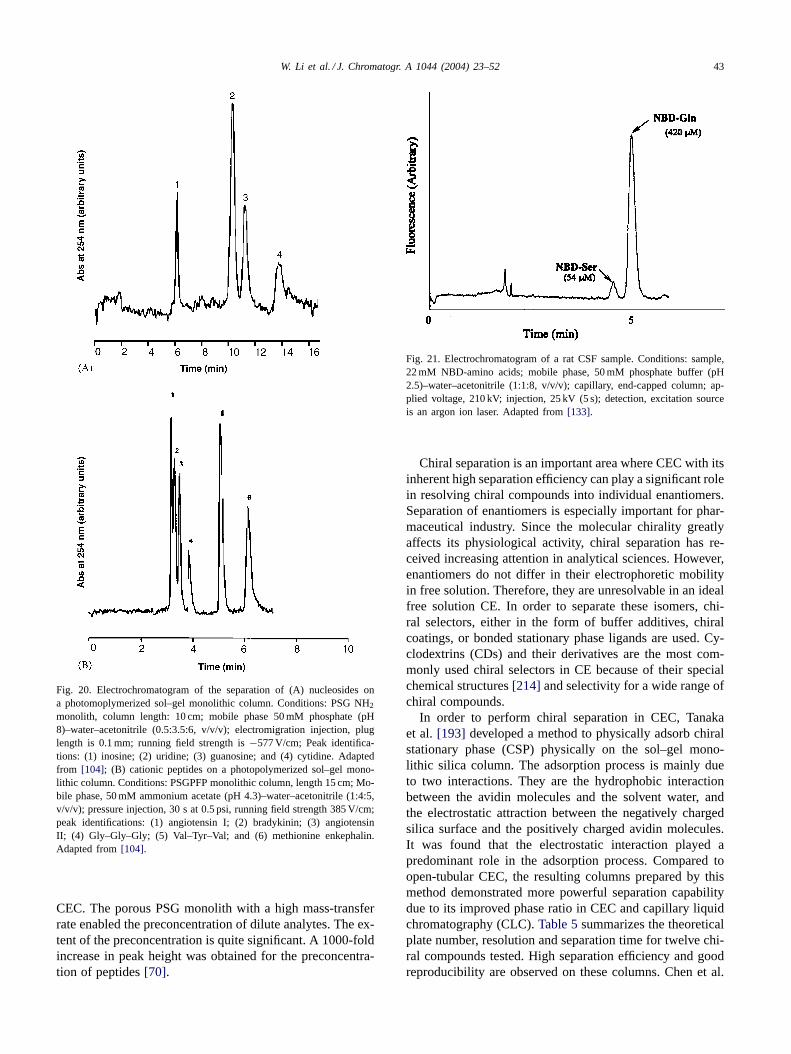
W. Li et al. / J. Chromatogr. A 1044 (2004) 23–52 43
Fig. 20. Electrochromatogram of the separation of (A) nucleosides ona photomoplymerized sol–gel monolithic column. Conditions: PSG NH2
monolith, column length: 10 cm; mobile phase 50 mM phosphate (pH8)–water–acetonitrile (0.5:3.5:6, v/v/v); electromigration injection, pluglength is 0.1 mm; running field strength is −577 V/cm; Peak identifica-tions: (1) inosine; (2) uridine; (3) guanosine; and (4) cytidine. Adaptedfrom [104]; (B) cationic peptides on a photopolymerized sol–gel mono-lithic column. Conditions: PSGPFP monolithic column, length 15 cm; Mo-bile phase, 50 mM ammonium acetate (pH 4.3)–water–acetonitrile (1:4:5,v/v/v); pressure injection, 30 s at 0.5 psi, running field strength 385 V/cm;peak identifications: (1) angiotensin I; (2) bradykinin; (3) angiotensinII; (4) Gly–Gly–Gly; (5) Val–Tyr–Val; and (6) methionine enkephalin.Adapted from [104].
CEC. The porous PSG monolith with a high mass-transferrate enabled the preconcentration of dilute analytes. The ex-tent of the preconcentration is quite significant. A 1000-foldincrease in peak height was obtained for the preconcentra-tion of peptides [70].
Fig. 21. Electrochromatogram of a rat CSF sample. Conditions: sample,22 mM NBD-amino acids; mobile phase, 50 mM phosphate buffer (pH2.5)–water–acetonitrile (1:1:8, v/v/v); capillary, end-capped column; ap-plied voltage, 210 kV; injection, 25 kV (5 s); detection, excitation sourceis an argon ion laser. Adapted from [133].
Chiral separation is an important area where CEC with itsinherent high separation efficiency can play a significant rolein resolving chiral compounds into individual enantiomers.Separation of enantiomers is especially important for phar-maceutical industry. Since the molecular chirality greatlyaffects its physiological activity, chiral separation has re-ceived increasing attention in analytical sciences. However,enantiomers do not differ in their electrophoretic mobilityin free solution. Therefore, they are unresolvable in an idealfree solution CE. In order to separate these isomers, chi-ral selectors, either in the form of buffer additives, chiralcoatings, or bonded stationary phase ligands are used. Cy-clodextrins (CDs) and their derivatives are the most com-monly used chiral selectors in CE because of their specialchemical structures [214] and selectivity for a wide range ofchiral compounds.
In order to perform chiral separation in CEC, Tanakaet al. [193] developed a method to physically adsorb chiralstationary phase (CSP) physically on the sol–gel mono-lithic silica column. The adsorption process is mainly dueto two interactions. They are the hydrophobic interactionbetween the avidin molecules and the solvent water, andthe electrostatic attraction between the negatively chargedsilica surface and the positively charged avidin molecules.It was found that the electrostatic interaction played apredominant role in the adsorption process. Compared toopen-tubular CEC, the resulting columns prepared by thismethod demonstrated more powerful separation capabilitydue to its improved phase ratio in CEC and capillary liquidchromatography (CLC). Table 5 summarizes the theoreticalplate number, resolution and separation time for twelve chi-ral compounds tested. High separation efficiency and goodreproducibility are observed on these columns. Chen et al.
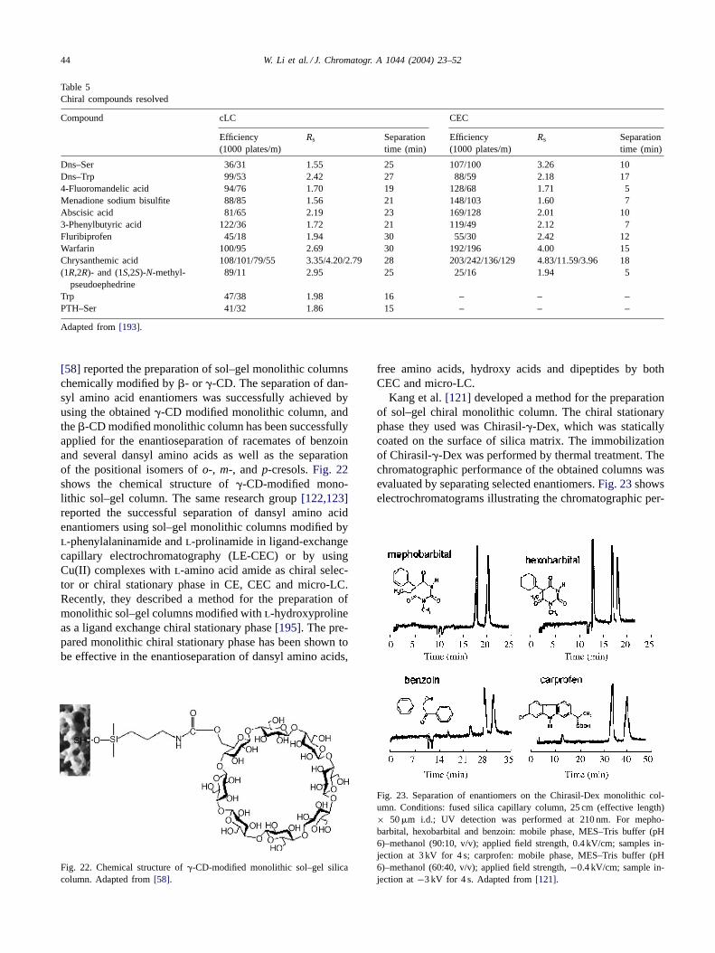
44 W. Li et al. / J. Chromatogr. A 1044 (2004) 23–52
Table 5Chiral compounds resolved
Compound cLC CEC
Efficiency(1000 plates/m)
Rs Separationtime (min)
Efficiency(1000 plates/m)
Rs Separationtime (min)
Dns–Ser 36/31 1.55 25 107/100 3.26 10Dns–Trp 99/53 2.42 27 88/59 2.18 174-Fluoromandelic acid 94/76 1.70 19 128/68 1.71 5Menadione sodium bisulfite 88/85 1.56 21 148/103 1.60 7Abscisic acid 81/65 2.19 23 169/128 2.01 103-Phenylbutyric acid 122/36 1.72 21 119/49 2.12 7Fluribiprofen 45/18 1.94 30 55/30 2.42 12Warfarin 100/95 2.69 30 192/196 4.00 15Chrysanthemic acid 108/101/79/55 3.35/4.20/2.79 28 203/242/136/129 4.83/11.59/3.96 18(1R,2R)- and (1S,2S)-N-methyl-
pseudoephedrine89/11 2.95 25 25/16 1.94 5
Trp 47/38 1.98 16 – – –PTH–Ser 41/32 1.86 15 – – –
Adapted from [193].
[58] reported the preparation of sol–gel monolithic columnschemically modified by �- or �-CD. The separation of dan-syl amino acid enantiomers was successfully achieved byusing the obtained �-CD modified monolithic column, andthe �-CD modified monolithic column has been successfullyapplied for the enantioseparation of racemates of benzoinand several dansyl amino acids as well as the separationof the positional isomers of o-, m-, and p-cresols. Fig. 22shows the chemical structure of �-CD-modified mono-lithic sol–gel column. The same research group [122,123]reported the successful separation of dansyl amino acidenantiomers using sol–gel monolithic columns modified byl-phenylalaninamide and l-prolinamide in ligand-exchangecapillary electrochromatography (LE-CEC) or by usingCu(II) complexes with l-amino acid amide as chiral selec-tor or chiral stationary phase in CE, CEC and micro-LC.Recently, they described a method for the preparation ofmonolithic sol–gel columns modified with l-hydroxyprolineas a ligand exchange chiral stationary phase [195]. The pre-pared monolithic chiral stationary phase has been shown tobe effective in the enantioseparation of dansyl amino acids,
Fig. 22. Chemical structure of �-CD-modified monolithic sol–gel silicacolumn. Adapted from [58].
free amino acids, hydroxy acids and dipeptides by bothCEC and micro-LC.
Kang et al. [121] developed a method for the preparationof sol–gel chiral monolithic column. The chiral stationaryphase they used was Chirasil-�-Dex, which was staticallycoated on the surface of silica matrix. The immobilizationof Chirasil-�-Dex was performed by thermal treatment. Thechromatographic performance of the obtained columns wasevaluated by separating selected enantiomers. Fig. 23 showselectrochromatograms illustrating the chromatographic per-
Fig. 23. Separation of enantiomers on the Chirasil-Dex monolithic col-umn. Conditions: fused silica capillary column, 25 cm (effective length)× 50 �m i.d.; UV detection was performed at 210 nm. For mepho-barbital, hexobarbital and benzoin: mobile phase, MES–Tris buffer (pH6)–methanol (90:10, v/v); applied field strength, 0.4 kV/cm; samples in-jection at 3 kV for 4 s; carprofen: mobile phase, MES–Tris buffer (pH6)–methanol (60:40, v/v); applied field strength, −0.4 kV/cm; sample in-jection at −3 kV for 4 s. Adapted from [121].
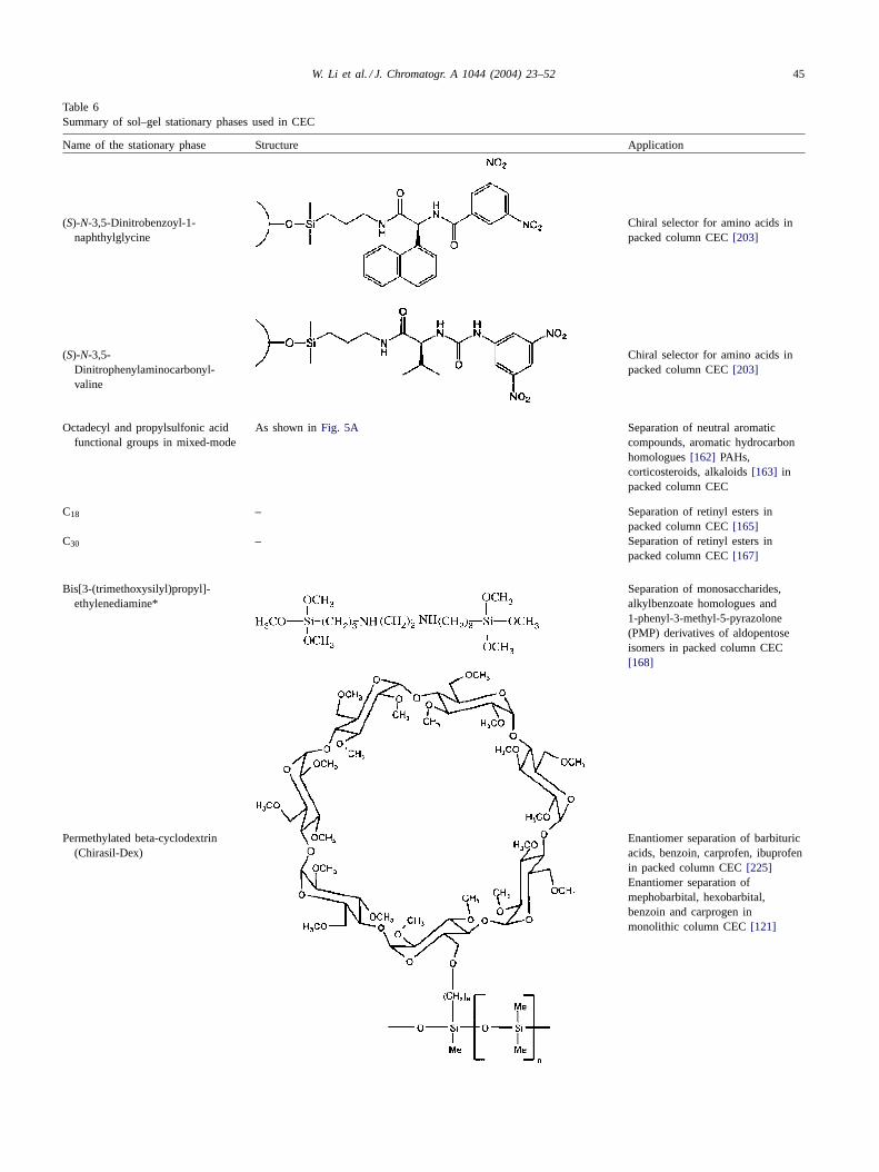
W. Li et al. / J. Chromatogr. A 1044 (2004) 23–52 45
Table 6Summary of sol–gel stationary phases used in CEC
Name of the stationary phase Structure Application
(S)-N-3,5-Dinitrobenzoyl-1-naphthylglycine
Chiral selector for amino acids inpacked column CEC [203]
(S)-N-3,5-Dinitrophenylaminocarbonyl-valine
Chiral selector for amino acids inpacked column CEC [203]
Octadecyl and propylsulfonic acidfunctional groups in mixed-mode
As shown in Fig. 5A Separation of neutral aromaticcompounds, aromatic hydrocarbonhomologues [162] PAHs,corticosteroids, alkaloids [163] inpacked column CEC
C18 – Separation of retinyl esters inpacked column CEC [165]
C30 – Separation of retinyl esters inpacked column CEC [167]
Bis[3-(trimethoxysilyl)propyl]-ethylenediamine*
Separation of monosaccharides,alkylbenzoate homologues and1-phenyl-3-methyl-5-pyrazolone(PMP) derivatives of aldopentoseisomers in packed column CEC[168]
Permethylated beta-cyclodextrin(Chirasil-Dex)
Enantiomer separation of barbituricacids, benzoin, carprofen, ibuprofenin packed column CEC [225]Enantiomer separation ofmephobarbital, hexobarbital,benzoin and carprogen inmonolithic column CEC [121]
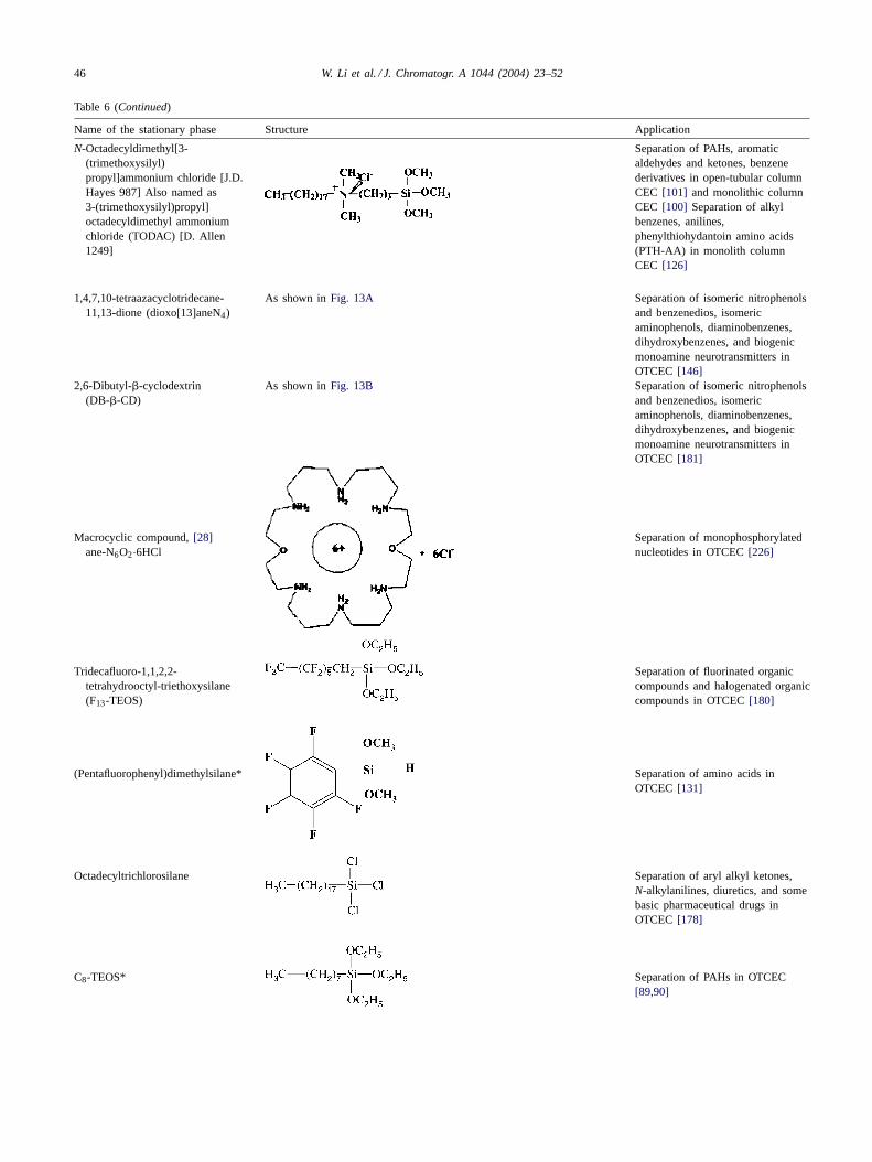
46 W. Li et al. / J. Chromatogr. A 1044 (2004) 23–52
Table 6 (Continued)
Name of the stationary phase Structure Application
N-Octadecyldimethyl[3-(trimethoxysilyl)propyl]ammonium chloride [J.D.Hayes 987] Also named as3-(trimethoxysilyl)propyl]octadecyldimethyl ammoniumchloride (TODAC) [D. Allen1249]
Separation of PAHs, aromaticaldehydes and ketones, benzenederivatives in open-tubular columnCEC [101] and monolithic columnCEC [100] Separation of alkylbenzenes, anilines,phenylthiohydantoin amino acids(PTH-AA) in monolith columnCEC [126]
1,4,7,10-tetraazacyclotridecane-11,13-dione (dioxo[13]aneN4)
As shown in Fig. 13A Separation of isomeric nitrophenolsand benzenedios, isomericaminophenols, diaminobenzenes,dihydroxybenzenes, and biogenicmonoamine neurotransmitters inOTCEC [146]
2,6-Dibutyl-�-cyclodextrin(DB-�-CD)
As shown in Fig. 13B Separation of isomeric nitrophenolsand benzenedios, isomericaminophenols, diaminobenzenes,dihydroxybenzenes, and biogenicmonoamine neurotransmitters inOTCEC [181]
Macrocyclic compound, [28]ane-N6O2·6HCl
Separation of monophosphorylatednucleotides in OTCEC [226]
Tridecafluoro-1,1,2,2-tetrahydrooctyl-triethoxysilane(F13-TEOS)
Separation of fluorinated organiccompounds and halogenated organiccompounds in OTCEC [180]
(Pentafluorophenyl)dimethylsilane* Separation of amino acids inOTCEC [131]
Octadecyltrichlorosilane Separation of aryl alkyl ketones,N-alkylanilines, diuretics, and somebasic pharmaceutical drugs inOTCEC [178]
C8-TEOS* Separation of PAHs in OTCEC[89,90]
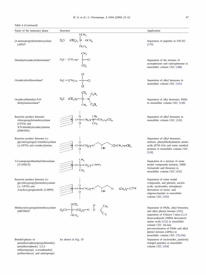
W. Li et al. / J. Chromatogr. A 1044 (2004) 23–52 47
Table 6 (Continued)
Name of the stationary phase Structure Application
(3-aminopropyl)trimethoxysilane(APS)*
Separation of peptides in OTCEC[179]
Dimethyloctadecylchlorosilane* Separation of the mixture ofacetophenone and valerophenone inmonolithic column CEC [188]
Octadecyltrichlorosilane* Separation of alkyl benzenes inmonolithic column CEC [191]
Octadecyldimethyl-N,N-diethylaminosilane*
Separation of alky benzenes, PAHsin monolithic column CEC [128]
Reaction product betweenchloropropyltrimethoxysilane(CPTS) andN,N-dimethyloctadecylamine(DMODA)
Separation of alkyl benzenes inmonolithic column CEC [126]
Reaction product between (�-glycidoxypropyl) trimethoxysilane(�-GPTS) and octadecylamine.
Separation of alkyl benzenes,anilines, phenylthiohydantoin aminoacids (PTH-AA) and some standardproteins in monolithic column CEC[126]
3-Cyanopropyldimethylchlorosilane(3-CPDCS)
Separation of a mixture of somemodel compounds (toluene, DMF,formamide and thiourea) inmonolithic column CEC [192]
Reaction product between (�-glycidoxypropyl)trimethoxysilane(�- GPTS) and3-hydroxypropionitrile (3-HPN)
Separation of some modelcompounds, and phenols, nucleicacids, nucleosides, nitrophenylderivatives of mono- andoligosaccharides in monolithiccolumn CEC [192]
Methacryloxypropyltrimethoxysilane(MPTMS)*
Separation of PAHs, alkyl benzenes,and alkyl phenyl ketones [105],separation of 4-fluoro-7-nitro-2,1,3-benzoxadiazole (NBD) derivatizedamino acids [133] in monolithiccolumn CEC On-linepreconcentration of PAHs and alkylphenyl ketones (APKs) inmonolithic column CEC [70,194]
Bonded-phases ofpentafluorophenylpropyldimethyl,pentafluorophenyl, 3,3,3-trifluoropropyl, n-octadimethyl,perfluorohexyl, and aminopropyl
As shown in Fig. 19 Separation of nucleosides, positivelycharged peptides in monolithiccolumn CEC [104]
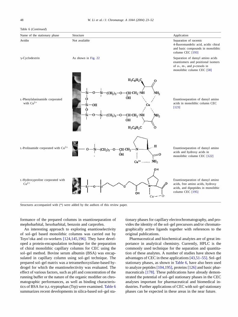
48 W. Li et al. / J. Chromatogr. A 1044 (2004) 23–52
Table 6 (Continued)
Name of the stationary phase Structure Application
Avidin Not available Separation of racemic4-fluoromandelic acid, acidic chiraland basic compounds in monolithiccolumn CEC [193]
�-Cyclodextrin As shown in Fig. 22 Separation of dansyl amino acidsenantiomers and positional isomersof o-, m-, and p-cresols inmonolithic column CEC [58]
l-Phenylalaninamide corporatedwith Cu2+
Enantioseparation of dansyl aminoacids in monolithic column CEC[123]
l-Prolinamide corporated with Cu2+ Enantioseparation of dansyl aminoacids and hydroxy acids inmonolithic column CEC [122]
l-Hydroxyproline corporated withCu2+
Enantioseparation of dansyl aminoacids, free amino acids, hydroxyacids, and dipeptides in monolithiccolumn CEC [195]
Structures accompanied with (*) were added by the authors of this review paper.
formance of the prepared columns in enantioseparation ofmephobarbital, hexobarbital, benzoin and carprofen.
An interesting approach to exploring enantioselectivityof sol–gel based monolithic columns was carried out byToyo’oka and co-workers [124,145,196]. They have devel-oped a protein-encapsulation technique for the preparationof chiral monolithic capillary columns for CEC using thesol–gel method. Bovine serum albumin (BSA) was encap-sulated in capillary column using sol–gel technique. Theprepared sol–gel matrix was a tetramethoxysilane-based hy-drogel for which the enantioselectivity was evaluated. Theeffect of various factors, such as pH and concentration of therunning buffer or the nature of the organic modifier on chro-matographic performances, as well as binding characteris-tics of BSA for d,l-tryptophan (Trp) were examined. Table 6summarizes recent developments in silica-based sol–gel sta-
tionary phases for capillary electrochromatography, and pro-vides the identity of the sol–gel precursors and/or chromato-graphically active ligands together with references to theoriginal publications.
Pharmaceutical and biochemical analytes are of great im-portance in analytical chemistry. Currently, HPLC is thecommonly used technique for the separation and quantita-tion of these analytes. A number of studies have shown theadvantages of CEC in these applications [43,51–55]. Sol–gelstationary phases, as shown in Table 6, have also been usedto analyze peptides [104,195], proteins [126] and basic phar-maceuticals [178]. These publications have already demon-strated the potential of sol–gel stationary phases in the CECanalyses important for pharmaceutical and biomedical in-dustries. Further applications of CEC with sol–gel stationaryphases can be expected in these areas in the near future.
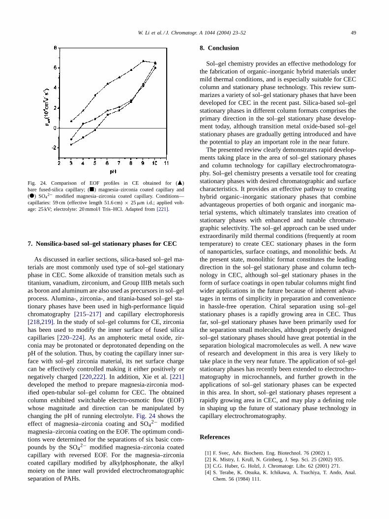
W. Li et al. / J. Chromatogr. A 1044 (2004) 23–52 49
Fig. 24. Comparison of EOF profiles in CE obtained for (�)bare fused-silica capillary; (�) magnesia–zirconia coated capillary and(�) SO4
2− modified magnesia–zirconia coated capillary. Conditions—capillaries: 59 cm (effective length 51.6 cm) × 25 �m i.d.; applied volt-age: 25 kV; electrolyte: 20 mmol/l Tris–HCl. Adapted from [221].
7. Nonsilica-based sol–gel stationary phases for CEC
As discussed in earlier sections, silica-based sol–gel ma-terials are most commonly used type of sol–gel stationaryphase in CEC. Some alkoxide of transition metals such astitanium, vanadium, zirconium, and Group IIIB metals suchas boron and aluminum are also used as precursors in sol–gelprocess. Alumina-, zirconia-, and titania-based sol–gel sta-tionary phases have been used in high-performance liquidchromatography [215–217] and capillary electrophoresis[218,219]. In the study of sol–gel columns for CE, zirconiahas been used to modify the inner surface of fused silicacapillaries [220–224]. As an amphoteric metal oxide, zir-conia may be protonated or deprotonated depending on thepH of the solution. Thus, by coating the capillary inner sur-face with sol–gel zirconia material, its net surface chargecan be effectively controlled making it either positively ornegatively charged [220,222]. In addition, Xie et al. [221]developed the method to prepare magnesia-zirconia mod-ified open-tubular sol–gel column for CEC. The obtainedcolumn exhibited switchable electro-osmotic flow (EOF)whose magnitude and direction can be manipulated bychanging the pH of running electrolyte. Fig. 24 shows theeffect of magnesia–zirconia coating and SO4
2− modifiedmagnesia–zirconia coating on the EOF. The optimum condi-tions were determined for the separations of six basic com-pounds by the SO4
2− modified magnesia–zirconia coatedcapillary with reversed EOF. For the magnesia–zirconiacoated capillary modified by alkylphosphonate, the alkylmoiety on the inner wall provided electrochromatographicseparation of PAHs.
8. Conclusion
Sol–gel chemistry provides an effective methodology forthe fabrication of organic–inorganic hybrid materials undermild thermal conditions, and is especially suitable for CECcolumn and stationary phase technology. This review sum-marizes a variety of sol–gel stationary phases that have beendeveloped for CEC in the recent past. Silica-based sol–gelstationary phases in different column formats comprises theprimary direction in the sol–gel stationary phase develop-ment today, although transition metal oxide-based sol–gelstationary phases are gradually getting introduced and havethe potential to play an important role in the near future.
The presented review clearly demonstrates rapid develop-ments taking place in the area of sol–gel stationary phasesand column technology for capillary electrochromatogra-phy. Sol–gel chemistry presents a versatile tool for creatingstationary phases with desired chromatographic and surfacecharacteristics. It provides an effective pathway to creatinghybrid organic–inorganic stationary phases that combineadvantageous properties of both organic and inorganic ma-terial systems, which ultimately translates into creation ofstationary phases with enhanced and tunable chromato-graphic selectivity. The sol–gel approach can be used underextraordinarily mild thermal conditions (frequently at roomtemperature) to create CEC stationary phases in the formof nanoparticles, surface coatings, and monolithic beds. Atthe present state, monolithic format constitutes the leadingdirection in the sol–gel stationary phase and column tech-nology in CEC, although sol–gel stationary phases in theform of surface coatings in open tubular columns might findwider applications in the future because of inherent advan-tages in terms of simplicity in preparation and conveniencein hassle-free operation. Chiral separation using sol–gelstationary phases is a rapidly growing area in CEC. Thusfar, sol–gel stationary phases have been primarily used forthe separation small molecules, although properly designedsol–gel stationary phases should have great potential in theseparation biological macromolecules as well. A new waveof research and development in this area is very likely totake place in the very near future. The application of sol–gelstationary phases has recently been extended to electrochro-matography in microchannels, and further growth in theapplications of sol–gel stationary phases can be expectedin this area. In short, sol–gel stationary phases represent arapidly growing area in CEC, and may play a defining rolein shaping up the future of stationary phase technology incapillary electrochromatography.
References
[1] F. Svec, Adv. Biochem. Eng. Biotechnol. 76 (2002) 1.[2] K. Mistry, I. Krull, N. Grinberg, J. Sep. Sci. 25 (2002) 935.[3] C.G. Huber, G. Holzl, J. Chromatogr. Libr. 62 (2001) 271.[4] S. Terabe, K. Otsuka, K. Ichikawa, A. Tsuchiya, T. Ando, Anal.
Chem. 56 (1984) 111.
50 W. Li et al. / J. Chromatogr. A 1044 (2004) 23–52
[5] J.H. Knox, R. Boughtflower, Trends Anal. Chem. 19 (2000) 643.[6] K. Walhagen, K.K. Unger, M.T.W. Hearn, J. Chromatogr. A 887
(2000) 165.[7] C. Ericson, S. Hjertén, Anal. Chem. 71 (1999) 1621.[8] Y. Zhang, W. Shi, L. Zhang, H. Zou, J. Chromatogr. A 802 (1998)
59.[9] G. Choudhary, A. Apffel, H. Yin, W. Hancock, J. Chromatogr. A
887 (2000) 85.[10] L.A. Colón, G. Burgos, T.D. Maloney, J.M. Cintrón, R.L. Rodrı́guez,
Electrophoresis 21 (2000) 3965.[11] Z. Deyl, F. Svec (Eds.), Capillary Electrochromatography, vol. 62,
Journal of Chromatography Library, Elsevier, Amsterdam, 2001.[12] A. Dermaux, P. Sandra, Electrophoresis 20 (1999) 3027.[13] N.W. Smith, A.S. Carter-Finch, J. Chromatogr. A 892 (2000) 219.[14] Z. Deyl, I. Miksik, J. Chromatogr. Libr. 62 (2001) 341.[15] S. Eeltink, G.P. Rozing, W.Th. Kok, Electrophoresis 24 (2003) 3935.[16] V.T. Remcho, S.L. Clark, A. Doneau, G.S. Chirica, in: A.S. Rathore,
A. Gutmann (Eds.), Electrokinetic Phenomena: Principles and Ap-plications in Analytical Chemistry and Microchip Technology, Mar-cel Dekker, New York, 2004, pp. 345–425.
[17] C. Yan, R. Dadoo, H. Zhao, R.N. Zare, D.J. Rakestraw, Anal. Chem.67 (1995) 2026.
[18] K.W. Whitaker, Capillary Electrochromatographic Separations ofPolycyclic Aromatic Hydrocarbons, University of Tennessee,Knoxville, TN, 1998.
[19] B. Xin, M.L. Lee, Electrophoresis 20 (1999) 67.[20] Y. Fintschenko, W.-Y. Choi, S.M. Ngola, T.J. Shepodd, Fresenius’
J. Anal. Chem. 371 (2001) 174.[21] Z. Yao, G. Jiang, M. Ye, H. Zou, Int. J. Environ. Anal. Chem. 81
(2001) 15.[22] Y.-S. Fung, Y.H. Long, Electrophoresis 22 (2001) 2270.[23] Z. Liu, H. Zou, M. Ye, Electrophoresis 22 (2001) 1298.[24] Y.-S. Fung, Y.H. Long, J. Chromatogr. A 907 (2001) 301.[25] M. Saeed, M. Depala, D.H. Craston, I.G.M. Anderson, Chro-
matographia 49 (1999) 391.[26] K.D. Altria, N.W. Smith, C.H. Turnbull, J. Chromatogr. B 717
(1998) 341.[27] I.S. Lurie, T.S. Conver, V.L. Ford, Anal. Chem. 70 (1998) 4563.[28] W. Wei, G.A. Luo, G.Y. Hua, C. Yan, J. Chromatogr. A 817 (1998)
65.[29] M.M. Dittmann, K. Masuch, G.P. Rozing, J. Chromatogr. A 887
(2000) 209.[30] A.M. Enlund, G. Hagman, R. Isaksson, D. Westerlund, Trends Anal.
Chem. 21 (2002) 412.[31] S. Fanali, P. Catarcini, G. Blaschke, B. Chankvetadze, Electrophore-
sis 22 (2001) 3131.[32] J. Kang, D. Wistuba, V. Schurig, Electrophoresis 23 (2002) 4005.[33] L. Zhang, H. Zou, W. Shi, J. Ni, Y. Zhang, J. Cap. Electrophoresis
5 (1998) 97.[34] N.P. Cassells, C.S. Lane, M. Depala, M. Saeed, D.H. Craston,
Chemosphere 40 (2000) 609.[35] E. Dabek-Zlotorzynska, H. Chen, L. Ding, Electrophoresis 24
(2003) 4128.[36] C.G. Bailey, C. Yan, Anal. Chem. 70 (1998) 3275.[37] A. Hilmi, J.H.T. Luong, Electrophoresis 21 (2000) 1395.[38] A. Karcher, Z. El Rassi, Electrophoresis 20 (1999) 3280.[39] P.A. Cooper, K.M. Jessop, F. Moffatt, Electrophoresis 21 (2000)
1574.[40] V. Lopez-Avila, J. Benedicto, C. Yan, J. Chromatogr. Sci. 37 (1999)
165.[41] C.M. Polcaro, A. Berti, A. De Rossi, C. Desiderio, Chromatographia
57 (2003) 623.[42] J.A. Starkey, S. Abrantes, Y. Mechref, M.V. Novotny, J. Sep. Sci.
26 (2003) 1635.[43] A. Dermaux, P. Sandra, in: K.D. Bartle, P. Myers (Eds.), Capillary
Electrochromatography, Royal Society of Chemistry, Cambridge,2001, pp. 125–145.
[44] A. Dermaux, P. Sandra, M. Ksir, K.F.F. Zarrouck, J. High Resolut.Chromatogr. 21 (1998) 545.
[45] S.L. Abidi, S. Thiam, I.M. Warner, J. Chromatogr. A 949 (2002)195.
[46] S. Fanali, P. Catarcini, M.G. Quaglia, E. Camera, M. Rinaldi, M.Picardo, J. Pharm. Biomed. Anal. 29 (2002) 973.
[47] K.D. Altria, N.W. Smith, C.H. Turnbull, Chromatographia 46 (1997)664.
[48] I.S. Lurie, Forensic Sci. Int. 92 (1998) 125.[49] J.T. Lim, R.N. Zare, C.G. Bailey, D.J. Rakestraw, C. Yan, Elec-
trophoresis 21 (2000) 737.[50] I.S. Lurie, D.S. Anex, Y. Fintschenko, W.-Y. Choi, J. Chromatogr.
A 924 (2001) 421.[51] N.W. Smith, M.B. Evans, Chromatographia 38 (1994) 649.[52] K.D. Altria, M.A. Kelly, B.J. Clark, Trends Anal. Chem. 17 (1998)
204.[53] P.D.A. Angus, Dissertation, University of Kansas, Lawrence, KS,
1999.[54] M.R. Euerby, N.C. Gillott, in: K.D. Bartle, P. Myers (Eds.), Cap-
illary Electrochromatography, Royal Society of Chemistry, Cam-bridge, 2001, pp. 107–124.
[55] J. Jiskra, H.A. Claessens, C.A. Cramers, J. Sep. Sci. 26 (2003) 43.[56] H. Fu, W. Jin, H. Xiao, C. Xie, B. Guo, H. Zou, Electrophoresis
25 (2004) 600.[57] D. Hoegger, R. Freitag, J. Chromatogr. A 1004 (2003) 195.[58] Z. Chen, H. Ozawa, K. Uchiyama, T. Hobo, Electrophoresis 24
(2003) 2550.[59] M. Kato, M.T. Dulay, B.D. Bennett, J.P. Quirino, R.N. Zare, J.
Chromatogr. A 924 (2001) 187.[60] S. Zhang, J. Zhang, Cs. Horváth, J. Chromatogr. A 965 (2002) 83.[61] M. Ye, H. Zou, Z. Liu, R. Wu, Z. Lei, J. Ni, J. Pharm. Biomed.
Anal. 27 (2002) 651.[62] I.S. Krull, A. Sebag, R. Stevenson, J. Chromatogr. A 887 (2000)
137.[63] S. Suzuki, S. Honda, Chromatography 22 (2001) 171.[64] Z. El Rassi, in: Z. El Rassi (Ed.), Carbohydrate Analysis by Mod-
ern Chromatography and Electrophoresis, vol. 66, Journal of Chro-matography Library, Elsevier, Amerterdam, 2002, p. 597.
[65] M. Zhang, C. Yang, Z. El Rassi, Anal. Chem. 71 (1999) 3277.[66] A. Dermaux, P. Sandra, V. Ferraz, Electrophoresis 20 (1999) 74.[67] D.A. Stead, R.G. Reid, R.B. Taylor, J. Chromatogr. A 798 (1998)
259.[68] C. Huber, G. Choudhary, Cs. Horváth, Anal. Chem. 69 (1997) 4429.[69] R.M. Seifar, W.T. Kok, J.C. Kraak, H. Poppe, J. Chromatogr. A
808 (1998) 71.[70] J.P. Quirino, M.T. Dulay, R.N. Zare, Anal. Chem. 73 (2001) 5557.[71] S. Oguri, H. Tanagaki, M. Hamaya, M. Kato, T. Toyo’oka, Anal.
Chem. 75 (2003) 5240.[72] M.C. Breadmore, A.S. Palmer, M. Curran, M. Macka, N. Avdalovic,
P.R. Haddad, Anal. Chem. 74 (2002) 2112.[73] W. Wall, J. Li, Z. El Rassi, J. Sep. Sci. 25 (2002) 1231.[74] W. Li, D.P. Fries, A. Malik, Anal. Chem. 76 (2004) 218.[75] U. Pyell, J. Chromatogr. A 892 (2000) 257.[76] K.K. Unger, D. Kumar, M. Grün, G. Büchel, S. Lüdtke, Th. Adam,
K. Schumacher, S. Renker, J. Chromatogr. A 892 (2000) 47.[77] L.A. Colón, T.D. Maloney, J. Anspach, H. Colon, Adv. Chromatogr.
42 (2003) 43.[78] M. Pursch, L.C. Sander, J. Chromatogr. A 887 (2000) 313.[79] A. Malik, Electrophoresis 23 (2002) 3973.[80] C. Legido-Quigley, N.D. Marlin, V. Melin, A. Manz, N.W. Smith,
Electrophoresis 24 (2003) 917.[81] A.-M. Siouffi, J. Chromatogr. A 1000 (2003) 801.[82] J. Jiskra, H.A. Claessens, C.A. Cramers, J. Sep. Sci. 26 (2003)
1305.[83] Q. Tang, M.L. Lee, Trends Anal. Chem. 19 (2000) 648.[84] M. Ye, H. Zou, Z. Liu, J. Ni, Y. Zhang, J. Chromatogr. A 855
(1999) 137.
W. Li et al. / J. Chromatogr. A 1044 (2004) 23–52 51
[85] C.J. Brinker, G.W. Scherer, Sol–gel Science, Academic Press,Boston, MA, 1990.
[86] J.D. Mackenzie, D.R. Ulrich (Eds.), Ultrastructure Processing ofAdvanced Ceramics, Wiley, New York, 1988.
[87] H.J. Cortes, C.D. Pfeiffer, B.E. Richter, T.S. Stevens, J. High Res-olut. Chromatogr. Chromatogr. Commun. 10 (1987) 446.
[88] A.L. Crego, J.C. Diez-Masa, M.V. Dabrio, Anal. Chem. 65 (1993)1615.
[89] Y. Guo, L.A. Colón, Anal. Chem. 67 (1995) 2511.[90] Y. Guo, L.A. Colón, J. Microcol. Sep. 7 (1995) 485.[91] D. Wang, S.L. Chong, A. Malik, Anal. Chem. 69 (1997) 4566.[92] R. Cervini, G. Day, A. Hibberd, G. Sharp, Chem. Aust. 68 (2001)
16.[93] Z. Zeng, W. Qiu, H. Xing, Z. Huang, Anal. Sci. 16 (2000) 851.[94] C. Shende, A. Kabir, E. Townsend, A. Malik, Anal. Chem. 75
(2003) 3518.[95] H. Minakuchi, K. Nakanishi, N. Soga, N. Ishizuka, N. Tanaka,
Anal. Chem. 68 (1996) 3498.[96] N. Ishizuka, H. Kobayashi, H. Minakuchi, K. Nakanishi, K. Hirao,
K. Hosoya, T. Ikegami, N. Tanaka, J. Chromatogr. A 960 (2002) 85.[97] B. Channer, P.U. Uhl, M.R. Euerby, A.P. McKeown, H. Lomax,
G.G. Skellern, D.G. Watson, Chromatographia 58 (2003) 135.[98] J.D. Hayes, Ph.D. Dissertation, University of South Florida, Tampa,
FL, 2000.[99] J.D. Hayes, A. Malik, J. Chromatogr. B 695 (1997) 3.
[100] J.D. Hayes, A. Malik, Anal. Chem. 72 (2000) 4090.[101] J.D. Hayes, A. Malik, Anal. Chem. 73 (2001) 987.[102] K. Sakai-Kato, M. Kato, T. Toyo’oka, Anal. Chem. 74 (2002) 2943.[103] K. Sakai-Kato, M. Kato, T. Toyo’oka, Anal. Biochem. 308 (2002)
278.[104] M.T. Dulay, J.P. Quirino, B.D. Bennett, R.N. Zare, J. Sep. Sci. 25
(2002) 3.[105] M.T. Dulay, J.P. Quirino, B.D. Bennett, M. Kato, R.N. Zare, Anal.
Chem. 73 (2001) 3921.[106] S. Bigham, J. Medlar, A. Kabir, C. Shende, A. Alli, A. Malik,
Anal. Chem. 74 (2002) 752.[107] X. Li, Z. Zeng, S. Gao, H. Li, J. Chromatogr. A 1023 (2004) 15.[108] S.L. Chong, D. Wang, J.D. Hayes, B.W. Wilhite, A. Malik, Anal.
Chem. 69 (1997) 3889.[109] A. Malik, S.-L. Chong, in: J. Pawliszyn (Ed.), Applications of
Solid-Phase, Microextraction, Royal Society of Chemistry, Cam-bridge, 1999, pp. 73–91.
[110] R.C. Mehrotra, J. Non-Cryst. Solids 121 (1990) 1.[111] J. Sanchez, S.E. Rankin, A.V. McCormick, Ind. Eng. Chem. Res.
35 (1996) 117.[112] K.G. Sharp, J. Sol Gel Sci. Technol. 35 (1996) 35.[113] S. Yoda, S. Ohshima, K. Kamiya, A. Kawai, K. Uchida, A. Gotoh,
F. Ikazaki, J. Non-Cryst. Solids 208 (1996) 191.[114] F.A. Pavan, S.A. Gobbi, C.C. Moro, T.M. Costa, E.V. Benvenutti,
J. Porous Mater. 9 (2002) 307.[115] L. He, K. Powers, R.H. Baney, L. Gower, R.S. Duran, P. Sheth,
S.R. Carino, J. Non-Cryst. Solids 289 (2001) 97.[116] M. Kato, K. Sakai-Kato, T. Toyo’oka, M.T. Dulay, J.P. Quirino,
B.D. Bennett, R.N. Zare, J. Chromatogr. A 961 (2002) 45.[117] I.C. Tilgner, P. Fischer, F.M. Bohnen, H. Rehage, W.F. Maier,
Microporous Mater. 5 (1995) 77.[118] M.I. Sarwar, Z. Ahmad, Eur. Polym. J. 36 (2000) 89.[119] S. Constantin, R. Freitag, J. Sol Gel Sci. Technol. 28 (2003) 71.[120] Y. Zhao, R. Zhao, D. Shangguan, G. Liu, Electrophoresis 23 (2002)
2990.[121] J. Kang, D. Wistuba, V. Schurig, Electrophoresis 23 (2002) 1116.[122] Z. Chen, T. Hobo, Electrophoresis 22 (2001) 3339.[123] Z. Chen, T. Hobo, Anal. Chem. 73 (2001) 3348.[124] M. Kato, K. Sakai-Kato, N. Matsumoto, T. Toya’oka, Anal. Chem.
74 (2002) 1915.[125] D. Allen, Z. El Rassi, Electrophoresis 24 (2003) 408.[126] D. Allen, Z. El Rassi, Analyst 128 (2003) 1249.
[127] M.C. Breadmore, S. Shrinivasan, K.A. Wolfe, M.E. Power, J.P.Ferrance, B. Hosticka, P.M. Norris, J.P. Landers, Electrophoresis23 (2002) 3487.
[128] N. Ishizuka, H. Minakuchi, K. Nakanishi, N. Soga, K. Hosoya, N.Tanaka, Anal. Chem. 72 (2000) 1275.
[129] J. Martin, B. Hosticka, C. Lattimer, P.M. Norris, J. Non-Cryst.Solids 285 (2001) 222.
[130] P. Judeinstein, J. Titman, M. Stamm, H. Schmidt, Chem. Mater. 6(1994) 127.
[131] S. Constantin, R. Freitag, J. Sep. Sci. 25 (2002) 1245.[132] G.J.M. Bruin, P.P.H. Tock, J.C. Kraak, H. Poppe, J. Chromatogr.
517 (1990) 557.[133] M. Kato, H. Jin, K. Sakai-Kato, T. Toyo’oka, M.T. Dulay, R.N.
Zare, J. Chromatogr. A 1004 (2003) 209.[134] X. Zuo, K. Wang, L. Zhou, S. Huang, Electrophoresis 24 (2003)
3202.[135] M.C. Breadmore, S. Shrinivasan, J. Karlinsey, J.P. Ferrance, P.M.
Norris, J.P. Landers, Electrophoresis 24 (2003) 1261.[136] K. Morishima, B.D. Bennett, M.T. Dulay, J.P. Quirino, R.N. Zare,
J. Sep. Sci. 25 (2002) 1226.[137] N. Tanaka, H. Kobayashi, N. Ishizuka, H. Minakuchi, K. Nakanishi,
K. Hosoya, T. Ikegami, J. Chromatogr. A 965 (2002) 35.[138] R.M. Almeida, M.I. de Barros Marques, X. Orignac, J. Sol Gel.
Sci. Technol. 8 (1997) 293.[139] Y. Yan, Y. Hoshino, Z. Duan, S.R. Chaudhuri, Chem. Mater. 9
(1997) 2583.[140] J.D. Brennan, J.S. Hartman, E.I. Ilnicki, M. Rakic, Chem. Mater.
11 (1999) 1853.[141] A. Fidalgo, L.M. Ilharco, J. Non-Cryst. Solids 283 (2001) 144.[142] M. Pursch, A. Jager, T. Schneller, R. Brindle, K. Albert, E. Lindner,
Chem. Mater. 8 (1996) 1245.[143] S.A. Jone, S. Wong, J.M. Burlitch, S. Viswanathan, D.L. Kohlstedt,
Chem. Mater. 9 (1997) 2567.[144] L. Delattre, F. Babonneau, Chem. Mater. 9 (1997) 2385.[145] K. Sakai-Kato, M. kato, H. Nakakuki, T. Toyo’oka, J. Pharm.
Biomed. Anal. 31 (2003) 299.[146] Y. Wang, Z. Zeng, C. Xie, N. Guan, E. Fu, J. Cheng, Chro-
matographia 54 (2001) 475.[147] S.A. Rodriguez, L.A. Colón, Appl. Spectrosc. 55 (2001) 472.[148] N. Re, J. Non-Cryst. Solids 142 (1992) 1.[149] A.M. Fermier, L.A. Colón, J. Microcol. Sep. 10 (1998) 439.[150] M. Schmid, F. Bäuml, A.P. Köhne, T. Welsch, J. High Resolut.
Chromatogr. 22 (1999) 438.[151] X. Zhang, S. Huang, J. Chromatogr. A 910 (2001) 13.[152] C. Fujimoto, Anal. Sci. 18 (2000) 19.[153] S.M. Piraino, J.G. Dorsey, Anal. Chem. 75 (2003) 4292.[154] R.A. Carney, M.M. Robson, K.D. Bartle, P. Myers, J. High Resolut.
Chromatogr. 22 (1999) 29.[155] S.E. van den Bosch, S. Heemstra, J.C. Kraak, H. Poppe, J. Chro-
matogr. A 755 (1996) 165.[156] H. Rebscher, U. Pyell, Chromatographia 38 (1994) 737.[157] E.F. Hilder, C.W. Klampfl, M. Macka, P.R. Haddad, P. Myers,
Analyst 125 (2000) 1.[158] M.M. Robson, S.C.P. Roulin, S.M. Shariff, M.W. Raynor, K.D.
Bartle, A.A. Clifford, P. Myers, M.R. Euerby, C.M. Johnson, Chro-matographia 43 (1996) 313.
[159] M.T. Dulay, R.P. Kulkarni, R.N. Zare, Anal. Chem. 70 (1998) 5103.[160] C.K. Ratnayake, C.S. Oh, M.P. Henry, J. Chromatogr. A 887 (2000)
277.[161] Q. Tang, B. Xin, M.L. Lee, J. Chromatogr. A 837 (1999) 35.[162] Q. Tang, M.L. Lee, J. Chromatogr. A 887 (2000) 265.[163] Q. Tang, M.L. Lee, J. High Resolut. Chromatogr. 23 (2000) 73.[164] Q. Tang, N. Wu, M.L. Lee, J. Microcol. Sep. 11 (1999) 550.[165] L. Roed, E. Lundanes, T. Greibrokk, J. Chromatogr. A 890 (2000)
347.[166] L. Roed, E. Lundanes, T. Greibrokk, J. Microcol. Sep. 12 (2000)
561.
52 W. Li et al. / J. Chromatogr. A 1044 (2004) 23–52
[167] L. Roed, E. Lundanes, L. Greibrokk, J. Sep. Sci. 24 (2001) 435.[168] S. Suzuki, Y. Kuwahara, K. Makiura, S. Honda, J. Chromatogr. A
873 (2000) 247.[169] K.J. Reynolds, L.A. Colón, J. Liq. Chromatogr. Rel. Technol. 23
(2000) 161.[170] K.J. Reynolds, L.A. Colón, Analyst 123 (1998) 1493.[171] Q. Tang, Ph.D. Dissertation, Brigham Young University, Provo, UT,
2000.[172] T. Adam, K.K. Unger, M.M. Dittmann, G.P. Rozing, J. Chromatogr.
A 887 (2000) 327.[173] T.D. Maloney, L.A. Colón, J. Sep. Sci. 25 (2002) 1215.[174] R. Freitag, S. Constantin, J. Sep. Sci. 26 (2003) 835.[175] S. Constantin, R. Freitag, D. Solignac, A. Sayah, M.A.M. Gijs,
Sens. Actuat. B 78 (2001) 267.[176] S. Constantin, R. Freitag, J. Chromatogr. A 887 (2000) 253.[177] S.A. Rodriguez, L.A. Colón, Anal. Chim. Acta 397 (1999) 207.[178] S. Dube, R.M. Smith, Chromatographia 57 (2003) 485.[179] J.-T. Wu, P. Huang, M.X. Li, M.G. Qian, D.M. Lubman, Anal.
Chem. 69 (1997) 320.[180] P. Narang, L.A. Colón, J. Chromatogr. A 773 (1997) 65.[181] Y. Wang, Z. Zeng, N. Guan, J. Cheng, Electrophoresis 22 (2001)
2167.[182] C.P. Kapnissi-Christodoulou, X. Zhu, I.M. Warner, Electrophoresis
24 (2003) 3917.[183] F. Li, H. Jin, J. Gu, R. Fu, J. Beijing Inst. Technol. 5 (1996) 122.[184] F. Li, H. Zhang, D. Gao, G. Lu, J. Gu, R. Fu, Chin. Sci. Bull. 43
(1998) 790.[185] M.-J. Xie, Y.-Q. Feng, S.-L. Da, Fenxi Kexue Xuebao 19 (2003) 1.[186] M. Ye, H. Zou, Z. Liu, J. Ni, Q. Zhuang, Y. Zhang, Sepu 17 (1999)
142.[187] Y. Wang, Z. Zeng, N. Guan, E. Fu, J. Cheng, Fenxi Huaxue 30
(2002) 227.[188] C. Fujimoto, J. High Resolut. Chromatogr. 23 (2000) 89.[189] S. Hjertén, Y.-M. Li, J.-L. Liao, J. Mohammad, K. Nakazato, G.
Pettersson, Nature 356 (1992) 810.[190] F. Svec, J.M.J. Fréchet, Science 273 (1996) 205.[191] N. Tanaka, H. Nagayama, H. Kobayashi, T. Ikegami, K. Hosoya,
J. High Resolut. Chromatogr. 23 (2000) 111.[192] D. Allen, Z. El Rassi, J. Chromatogr. A 1029 (2004) 239.[193] Z. Liu, K. Otsuka, S. Terabe, M. Motokawa, N. Tanaka, Elec-
trophoresis 23 (2002) 2973.[194] J.P. Quirino, M.T. Dulay, B.D. Bennett, R.N. Zare, Anal. Chem. 73
(2001) 5539.[195] Z. Chen, T. Nishiyama, K. Uchiyama, T. Hobo, Anal. Chim. Acta
501 (2004) 17.[196] M. Kato, N. Matsumoto, K. Sakai-Kato, T. Toyo’oka, J. Pharm.
Biomed. Anal. 30 (2003) 1845.[197] D. Allen, Z. El Rassi, Electrophoresis 24 (2003) 3962.[198] L. Yan, L. Zhang, Q. Zhang, L. Tong, Y. Feng, W. Zhang, Y. Zhang,
Fenxin Huaxue 32 (2004) 1.
[199] L.A. Colón, T.D. Maloney, A.M. Fermier, J. Chromatogr. A 887(2000) 43.
[200] B. Behnke, J. Johansson, S. Zhang, E. Bayer, S. Nilsson, J. Chro-matogr. A 818 (1998) 257.
[201] G.A. Lord, D.B. Gordon, P. Myers, B.W. King, J. Chromatogr. A768 (1997) 9.
[202] M. Mayer, E. Rapp, C. Marck, J.M. Bruin, Electrophoresis 20(1999) 43.
[203] M. Kato, M.T. Dulay, B. Bennett, J. Chen, R.N. Zare, Electrophore-sis 21 (2000) 3145.
[204] C.K. Ratnayake, C.S. Oh, M.P. Henry, J. High Resolut. Chromatogr.23 (2000) 81.
[205] L.A. Colon, K. Reynolds, G. Burgos, T.D. Maloney, J. Lopez,Chromatography 20 (1999) 306.
[206] Y.S. Li, B. Li, N.Y. Han, B.J. Xu, J. Chromatogr. A 1021 (2003)183.
[207] A.-M. Siouffi, Spectra Anal. 31 (2002) 15.[208] H. Minakuchi, K. Nakanishi, N. Soga, N. Ishizuka, N. Tanaka, J.
Chromatogr. A 762 (1997) 135.[209] H. Minakuchi, K. Nakanishi, N. Soga, N. Ishizuka, N. Tanaka, J.
Chromatogr. A 797 (1998) 121.[210] H. Minakuchi, N. Ishizuka, K. Nakanishi, N. Soga, N. Tanaka, J.
Chromatogr. A 828 (1998) 83.[211] N. Ishizuka, H. Minakuchi, K. Nakanishi, N. Soga, N. Tanaka, J.
Chromatogr. A 797 (1998) 133.[212] N. Ishizuka, H. Minakuchi, K. Nakanishi, N. Soga, K. Hosoya, N.
Tanaka, J. High Resolut. Chromatogr. 21 (1998) 477.[213] K. Nakanishi, H. Minakuchi, N. Soga, N. Tanaka, J. Sol Gel Sci.
Technol. 8 (1997) 547.[214] B. Chankvetadze, Capillary Electrophoresis in Chiral Analysis, Wi-
ley, Chichester, 1997.[215] U. Trüdinger, G. Müller, K. Unger, J. Chromatogr. 535 (1990) 111.[216] M. Grün, A. Kurganov, S. Schacht, F. Schüth, K. Unger, J. Chro-
matogr. A 740 (1996) 1.[217] J.J. Pesek, M.T. Matyska, J.E. Sandoval, E.J. Williamsen, J. Liq.
Chromatogr. Rel. Technol. 19 (1996) 2843.[218] C. Fujimoto, Electrophoresis 23 (2002) 2929.[219] L. Xu, Y.-Q. Feng, Z.-G. Shi, S.-L. Da, Y.-Y. Ren, J. Chromatogr.
A 1028 (2004) 165.[220] M. Xie, Y. Feng, S. Da, J. Sep. Sci. 24 (2001) 62.[221] M. Xie, Y. Feng, S. Da, D. Meng, L. Ren, Anal. Chim. Acta 428
(2001) 255.[222] M. Crosnier de Bellaistre, O. Mathieu, J. Randon, J.L. Rocca, J.
Chromatogr. A 971 (2002) 199.[223] J. Randon, M. Crosnier de Bellaistre, J.L. Rocca, Chromatographia
57 (Suppl.) (2003) S/355.[224] D. Xia, Y.-Q. Feng, S.-L. Da, J. Liq. Chromatogr. Rel. Technol. 24
(2001) 1881.[225] D. Wistuba, V. Schurig, Electrophoresis 21 (2000) 3152.[226] S.-Y. Lin, W.-H. Chen, C.-Y. Liu, Electrophoresis 23 (2002) 1230.
Related Documents


![Capillary thermostatting in capillary electrophoresis · Capillary thermostatting in capillary electrophoresis ... 75 µm BF 3 Injection: ... 25-µm id BF 5 capillary. Voltage [kV]](https://static.cupdf.com/doc/110x72/5c176ff509d3f27a578bf33a/capillary-thermostatting-in-capillary-electrophoresis-capillary-thermostatting.jpg)