Chapter 1 SOLAR POWERED HOUSE 1.1 Introduction A house which generates electricity by means of solar energy is known as Solar Powered house. Solar power is the conversion of sunlight into electricity, either directly using photovoltaics (PV), or indirectly using concentrated solar power (CSP). Concentrated solar power systems use lenses or mirrors and tracking systems to focus a large area of sunlight into a small beam. Photovoltaics convert light into electric current using the photovoltaic effect. Photovoltaics were initially, and still are, used to power small and medium-sized applications, from the calculator powered by a single solar cell to off-grid homes powered by a photovoltaic array. They are an important and relatively inexpensive source of electrical energy where grid power is inconvenient, unreasonably expensive to connect, or simply unavailable. However, as the cost of solar electricity is falling, solar power is also increasingly being used even in grid-connected situations as a way to feed low-carbon energy into the grid. In our seminar topic we will take the use of solar photovoltaic panels to generate electricity for our daily use. Roshit Kadiru (11ERAEE208) 1 | Page Aravali Institute Of Technical Studies, Udaipur Electrical Dept.

Solar powered house report
Jan 28, 2015
A complete report on solar powered house with almost all the details needed. In this report you will find the load calculation, battery size calculation, inverter size calculation, solar panel size calculation, types of connection use for solar powered house
Welcome message from author
This document is posted to help you gain knowledge. Please leave a comment to let me know what you think about it! Share it to your friends and learn new things together.
Transcript
Chapter 1
SOLAR POWERED HOUSE
1.1 Introduction
A house which generates electricity by means of solar energy is known as Solar
Powered house.
Solar power is the conversion of sunlight into electricity, either directly using
photovoltaics (PV), or indirectly using concentrated solar power (CSP). Concentrated
solar power systems use lenses or mirrors and tracking systems to focus a large area of
sunlight into a small beam. Photovoltaics convert light into electric current using the
photovoltaic effect.
Photovoltaics were initially, and still are, used to power small and medium-sized
applications, from the calculator powered by a single solar cell to off-grid homes powered
by a photovoltaic array. They are an important and relatively inexpensive source of
electrical energy where grid power is inconvenient, unreasonably expensive to connect, or
simply unavailable. However, as the cost of solar electricity is falling, solar power is also
increasingly being used even in grid-connected situations as a way to feed low-carbon
energy into the grid.
In our seminar topic we will take the use of solar photovoltaic panels to generate
electricity for our daily use.
Roshit Kadiru (11ERAEE208) 1 | P a g eAravali Institute Of Technical Studies, Udaipur Electrical Dept.
Chapter 2
SOLAR ENERGY
2.1 Energy from the Sun
The Earth receives 174 petawatts (PW) of incoming solar radiation at the upper
atmosphere. Approximately 30% is reflected back to space while the rest is absorbed by
clouds, oceans and land masses. The spectrum of solar light at the Earth's surface is
mostly spread across the visible and near-infrared ranges with a small part in the near-
ultraviolet.
The total solar energy absorbed by Earth's atmosphere, oceans and land masses is
approximately 3,850,000 exajoules (EJ) per year. In 2002, this was more energy in one
hour than the world used in one year.
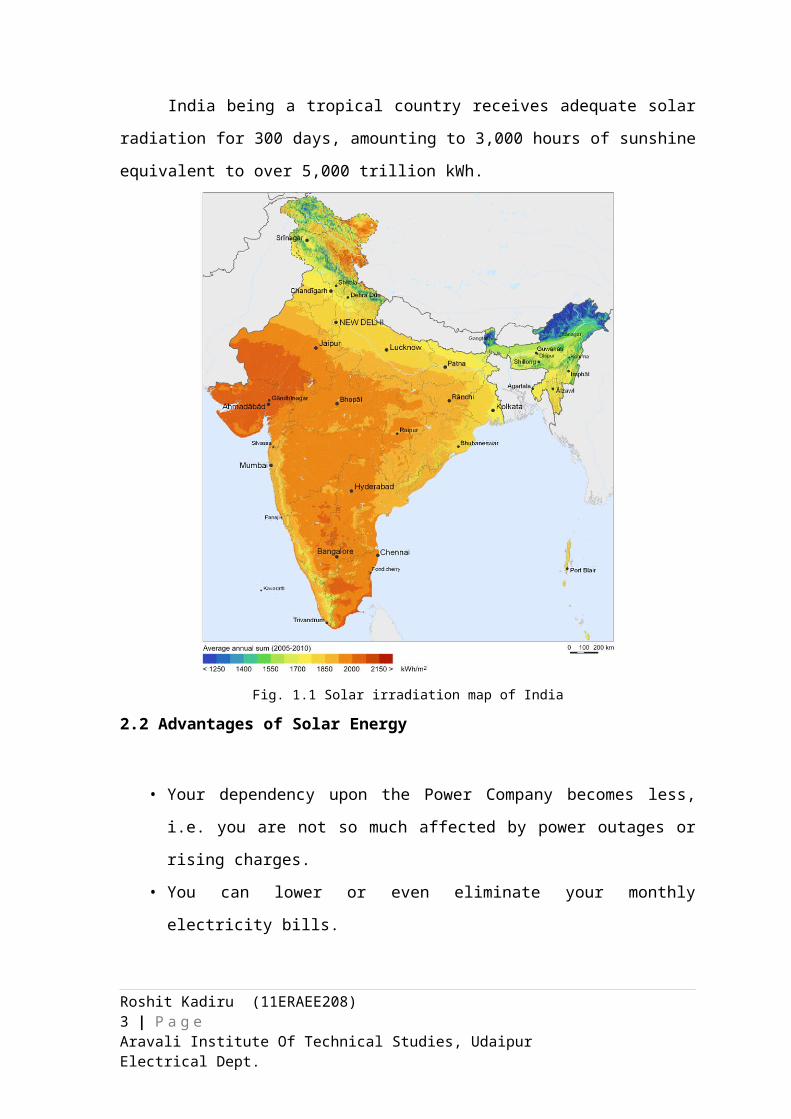
India being a tropical country receives adequate solar radiation for 300 days,
amounting to 3,000 hours of sunshine equivalent to over 5,000 trillion kWh.
Fig. 1.1 Solar irradiation map of India
Roshit Kadiru (11ERAEE208) 2 | P a g eAravali Institute Of Technical Studies, Udaipur Electrical Dept.
2.2 Advantages of Solar Energy
• Your dependency upon the Power Company becomes less, i.e. you are not so
much affected by power outages or rising charges.
• You can lower or even eliminate your monthly electricity bills.
• You will go green - fossil fuel-driven power stations will emit less greenhouse
gasses if enough houses use solar electricity as the demand will be less.
• Energy from the sun allows electricity to be produced in the place where it is
consumed (i.e. your home), also known as distributed generation. Since sunlight
hours overlap nicely with peak demand, PV panels produce electricity when it is
both most costly and most required.
• You will add more value to your property.
• Your solar power installation can operate with little maintenance or intervention
after initial setup.
• You can even get money from the Power Company for generating surplus
electricity that they can re-distribute, or get a rebate from the Power Company for
installing a solar power system (depending on where you live).
2.3 Disadvantages of Solar Energy
• Solar energy can only be harnessed when it is daytime and sunny.
• Solar collectors, panels and cells are relatively expensive to manufacture although
prices are falling rapidly.
• Solar power stations can be built but they do not match the power output of
similar sized conventional power stations. They are also very expensive.
• In countries such as the UK, the unreliable climate means that solar energy is also
unreliable as a source of energy. Cloudy skies reduce its effectiveness.
• Large areas of land are required to capture the suns energy. Collectors are usually
arranged together especially when electricity is to be produced and used in the
same location.
• Solar power is used to charge batteries so that solar powered devices can be used
at night. However, the batteries are large and heavy and need storage space. They
also need replacing from time to time.
Roshit Kadiru (11ERAEE208) 3 | P a g eAravali Institute Of Technical Studies, Udaipur Electrical Dept.
2.4 Advantages of Solar Panels
Solar panels are a great way to use sustainable, natural resources to create energy.
They can be used to collect sunlight and convert it into energy that can be used for
electricity.
You can convert any type of home or business into one that uses electricity
created from solar energy. Even if you don’t collect enough sunlight for all of your
electricity, you can collect enough of it to significantly reduce what you do use.
• Solar energy is a renewable, sustainable resource. Oil, on the other hand, is not
renewable or sustainable. Once it is gone, it is gone.
• Solar cells are totally silent. They can extract energy from the sun without making
any noise.
• Energy is non-polluting. Of all the advantages of solar energy over those of oil,
this is, perhaps, the most important. The burning of oil releases carbon dioxide
and other greenhouse gases and carcinogens into the air.
• Solar cells require very little maintenance. They have no moving parts that need to
be fixed and so last a long time. Although solar panels may be expensive to buy at
the onset, you can save money in the long run. After all, you do not have to pay
for energy from the sun. On the other hand, we are all aware of the rising cost of
oil.
As you can see, there are many benefits of solar energy. There are also many advantages
of solar energy which range from financial benefits to environmental benefits.
Roshit Kadiru (11ERAEE208) 4 | P a g eAravali Institute Of Technical Studies, Udaipur Electrical Dept.
Chapter 3
PHOTOVOLTAICS
3.1 History of Solar Cells
The photovoltaic effect was first experimentally demonstrated by French physicist
A. E. Becquerel. In 1839, at age 19, experimenting in his father's laboratory, he built the
world's first photovoltaic cell. Willoughby Smith first described the "Effect of Light on
Selenium during the passage of an Electric Current" in an article that was published in the
20 February 1873 issue of Nature. However, it was not until 1883 that the first solid state
photovoltaic cell was built, by Charles Fritts, who coated the semiconductor selenium
with an extremely thin layer of gold to form the junctions. The device was only around
1% efficient. In 1888 Russian physicist Aleksandr Stoletov built the first cell based on the
outer photoelectric effect discovered by Heinrich Hertz earlier in 1887.
Albert Einstein explained the underlying mechanism of light instigated carrier
excitation—the photoelectric effect—in 1905, for which he received the Nobel prize in
Physics in 1921. Russell Ohl patented the modern junction semiconductor solar cell in
1946, which was discovered while working on the series of advances that would lead to
the transistor.
The first practical photovoltaic cell was developed in 1954 at Bell Laboratories by
Daryl Chapin, Calvin Souther Fuller and Gerald Pearson. They used a diffused silicon p–
n junction that reached 6% efficiency, compared to the selenium cells that found it
difficult to reach 0.5%. Les Hoffman CEO of Hoffman Electronics Corporation had his
Semiconductor Division pioneer the fabrication and mass production of solar cells. From
1954 to 1960 Hoffman improved the efficiency of Solar Cells from 2% to 14%. At first,
cells were developed for toys and other minor uses, as the cost of the electricity they
produced was very high; in relative terms, a cell that produced 1 watt of electrical power
in bright sunlight cost about $250, comparing to $2 to $3 per watt for a coal plant.
Solar cells were brought from obscurity by the suggestion to add them, probably
due to the successes made by Hoffman Electronics, to the Vanguard I satellite, launched
in 1958. In the original plans, the satellite would be powered only by battery, and last a
short time while this ran down. By adding cells to the outside of the body, the mission
time could be extended with no major changes to the spacecraft or its power systems. In
Roshit Kadiru (11ERAEE208) 5 | P a g eAravali Institute Of Technical Studies, Udaipur Electrical Dept.
1959 the United States launched Explorer 6. It featured large solar arrays resembling
wings, which became a common feature in future satellites. These arrays consisted of
9600 Hoffman solar cells. There was some skepticism at first, but in practice the cells
proved to be a huge success, and solar cells were quickly designed into many new
satellites, notably Bell's own Telstar.
Improvements were slow over the next two decades, and the only widespread use
was in space applications where their power-to-weight ratio was higher than any
competing technology. However, this success was also the reason for slow progress;
space users were willing to pay anything for the best possible cells, there was no reason to
invest in lower-cost solutions if this would reduce efficiency. Instead, the price of cells
was determined largely by the semiconductor industry; their move to integrated circuits in
the 1960s led to the availability of larger boules at lower relative prices. As their price
fell, the price of the resulting cells did as well. However these effects were limited, and
by 1971 cell costs were estimated to be $100 per watt.
3.2 Photovoltaic Cell / Solar cell
A solar cell (also called a photovoltaic cell) is an electrical device that converts
the energy of light directly into electricity by the photovoltaic effect. It is a form of
photoelectric cell (in that its electrical characteristics—e.g. current, voltage, or resistance
—vary when light is incident upon it) which, when exposed to light, can generate and
support an electric current without being attached to any external voltage source, but do
require an external load for power consumption.
The term "photovoltaic" comes from the Greek φῶς (phōs) meaning "light", and
from "volt", the unit of electro-motive force, the volt, which in turn comes from the last
name of the Italian physicist Alessandro Volta, inventor of the battery (electrochemical
cell). The term "photo-voltaic" has been in use in English since 1849.
Photovoltaics is the field of technology and research related to the practical
application of photovoltaic cells in producing electricity from light, though it is often used
specifically to refer to the generation of electricity from sunlight. Cells can be described
as photovoltaic even when the light source is not necessarily sunlight (lamplight, artificial
light, etc.). In such cases the cell is sometimes used as a photodetector (for example
Roshit Kadiru (11ERAEE208) 6 | P a g eAravali Institute Of Technical Studies, Udaipur Electrical Dept.
infrared detectors), detecting light or other electromagnetic radiation near the visible
range, or measuring light intensity.
The operation of a photovoltaic (PV) cell requires 3 basic attributes:
• The absorption of light, generating either electron-hole pairs or exactions.
• The separation of charge carriers of opposite types.
• The separate extraction of those carriers to an external circuit.
3.3 Working of Solar Cell
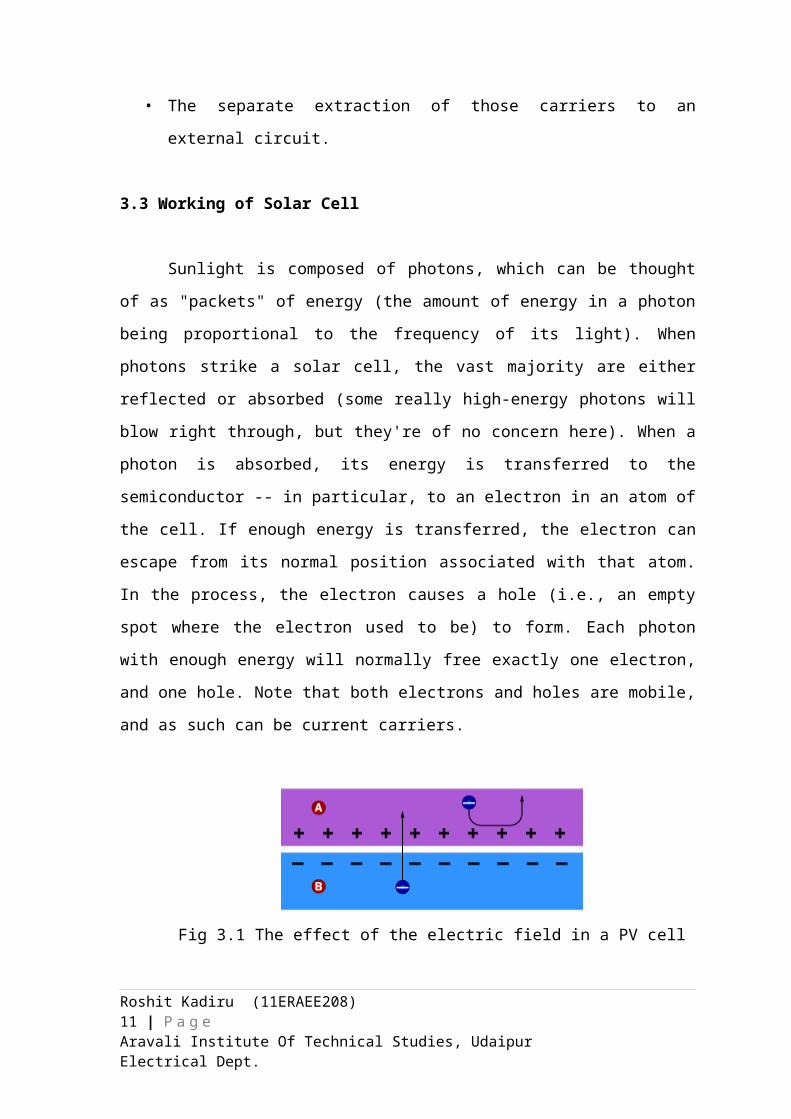
Sunlight is composed of photons, which can be thought of as "packets" of energy
(the amount of energy in a photon being proportional to the frequency of its light). When
photons strike a solar cell, the vast majority are either reflected or absorbed (some really
high-energy photons will blow right through, but they're of no concern here). When a
photon is absorbed, its energy is transferred to the semiconductor -- in particular, to an
electron in an atom of the cell. If enough energy is transferred, the electron can escape
from its normal position associated with that atom. In the process, the electron causes a
hole (i.e., an empty spot where the electron used to be) to form. Each photon with enough
energy will normally free exactly one electron, and one hole. Note that both electrons and
holes are mobile, and as such can be current carriers.
Fig 3.1 The effect of the electric field in a PV cell
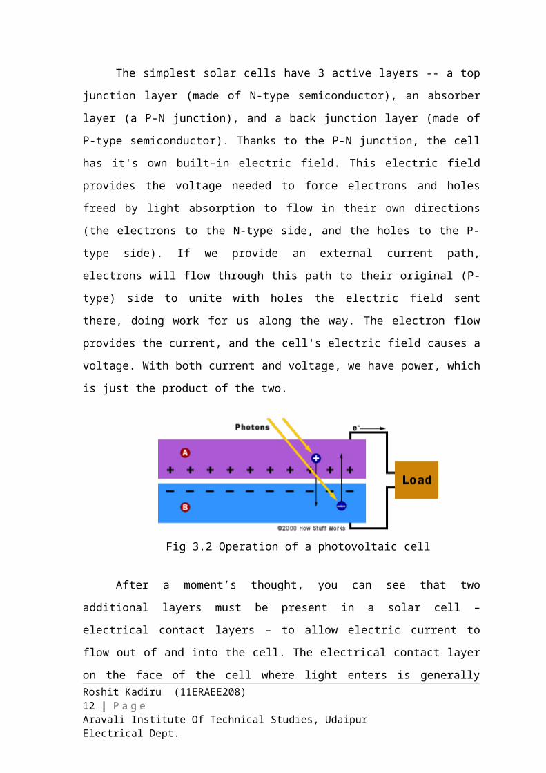
The simplest solar cells have 3 active layers -- a top junction layer (made of N-
type semiconductor), an absorber layer (a P-N junction), and a back junction layer (made
of P-type semiconductor). Thanks to the P-N junction, the cell has it's own built-in
electric field. This electric field provides the voltage needed to force electrons and holes
freed by light absorption to flow in their own directions (the electrons to the N-type side,
and the holes to the P-type side). If we provide an external current path, electrons will
flow through this path to their original (P-type) side to unite with holes the electric field
Roshit Kadiru (11ERAEE208) 7 | P a g eAravali Institute Of Technical Studies, Udaipur Electrical Dept.
sent there, doing work for us along the way. The electron flow provides the current, and
the cell's electric field causes a voltage. With both current and voltage, we have power,
which is just the product of the two.
Fig 3.2 Operation of a photovoltaic cell
After a moment’s thought, you can see that two additional layers must be present
in a solar cell –electrical contact layers – to allow electric current to flow out of and into
the cell. The electrical contact layer on the face of the cell where light enters is generally
present in some grid pattern and is composed of a good conductor such as a metal. The
grid pattern does not cover the entire face of the cell since grid materials, though good
electrical conductors are generally not transparent to light. Hence, the grid pattern must
be widely spaced to allow light to enter the solar cell but not to the extent that the
electrical contact layer will have difficulty collecting the current produced by the cell.
The back electrical contact layer has no such restrictions – it need simply provide an
electrical contact and thus covers the entire back surface of the cell.
Roshit Kadiru (11ERAEE208) 8 | P a g eAravali Institute Of Technical Studies, Udaipur Electrical Dept.
Chapter 4
SOLAR POWER SYSTEM
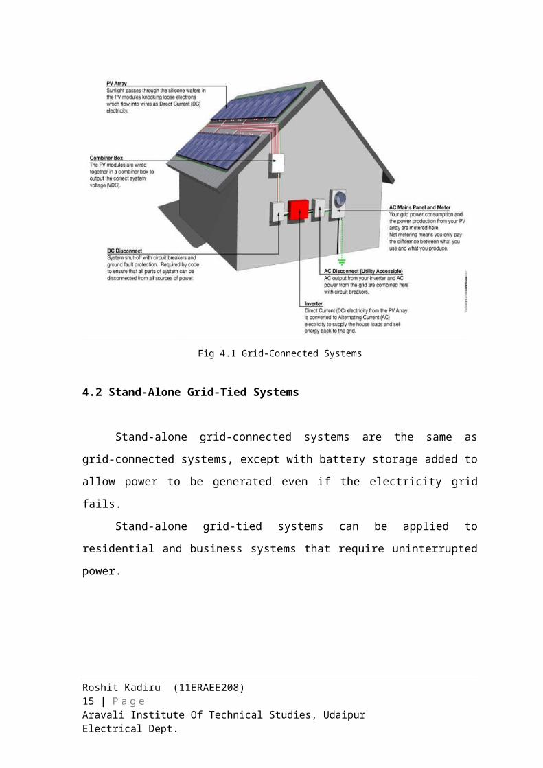
4.1 Grid-Connected Systems
In grid-connected or grid-tied systems, solar energy is used during the day by the
system owner. At night, the owner draws on the previously established electricity grid.
An addition benefit of the grid-tied system is that the solar system does not need to be
sized to meet peak loads—overages can be drawn from the grid. In many cases, surplus
energy generated during the day can be exported back to the grid. Grid-connected systems
must meet utility requirements. For example, inverters must not emit noise that can
interfere with equipment reception. Inverters must also switch off in cases of grid failure.
Finally, they must retain acceptable levels of harmonic distortion, such as voltage quality
and current output waveforms.
Grid-connected systems can be applied to residential installations.
Fig 4.1 Grid-Connected Systems
Roshit Kadiru (11ERAEE208) 9 | P a g eAravali Institute Of Technical Studies, Udaipur Electrical Dept.
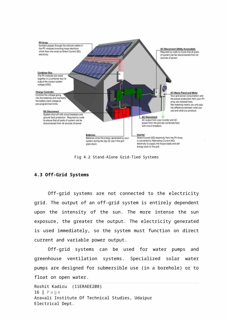
4.2 Stand-Alone Grid-Tied Systems
Stand-alone grid-connected systems are the same as grid-connected systems,
except with battery storage added to allow power to be generated even if the electricity
grid fails.
Stand-alone grid-tied systems can be applied to residential and business systems
that require uninterrupted power.
Fig 4.2 Stand-Alone Grid-Tied Systems
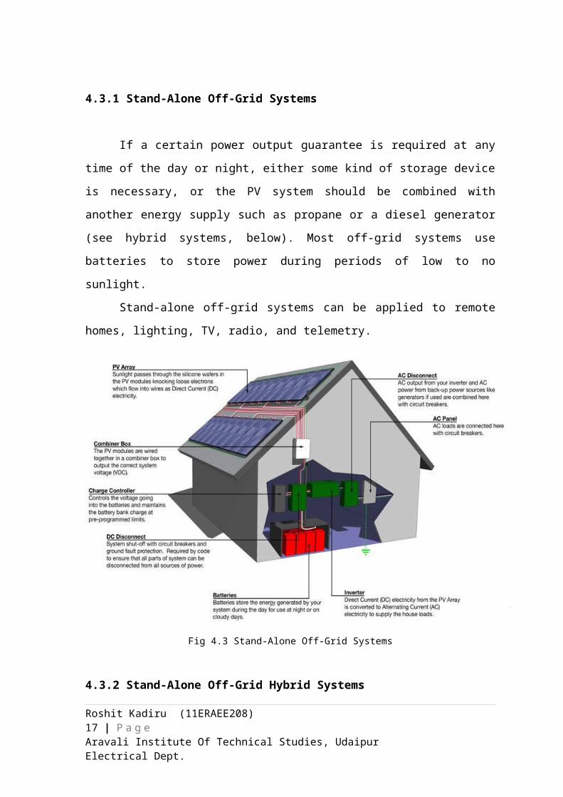
4.3 Off-Grid Systems
Off-grid systems are not connected to the electricity grid. The output of an off-
grid system is entirely dependent upon the intensity of the sun. The more intense the sun
exposure, the greater the output. The electricity generated is used immediately, so the
system must function on direct current and variable power output.
Roshit Kadiru (11ERAEE208) 10 | P a g eAravali Institute Of Technical Studies, Udaipur Electrical Dept.
Off-grid systems can be used for water pumps and greenhouse ventilation
systems. Specialized solar water pumps are designed for submersible use (in a borehole)
or to float on open water.
4.3.1 Stand-Alone Off-Grid Systems
If a certain power output guarantee is required at any time of the day or night,
either some kind of storage device is necessary, or the PV system should be combined
with another energy supply such as propane or a diesel generator (see hybrid systems,
below). Most off-grid systems use batteries to store power during periods of low to no
sunlight.
Stand-alone off-grid systems can be applied to remote homes, lighting, TV, radio,
and telemetry.
Fig 4.3 Stand-Alone Off-Grid Systems
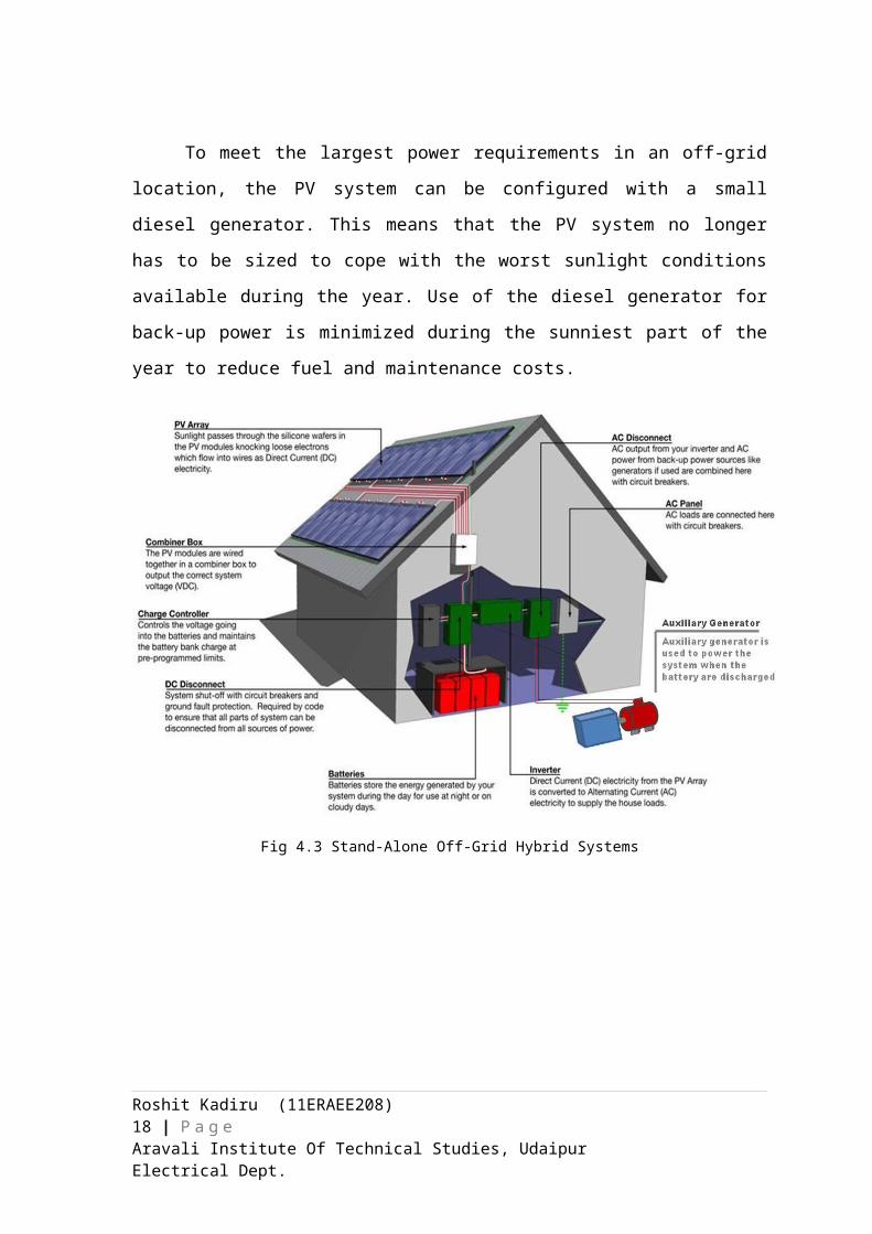
4.3.2 Stand-Alone Off-Grid Hybrid Systems
To meet the largest power requirements in an off-grid location, the PV system can
be configured with a small diesel generator. This means that the PV system no longer has
Roshit Kadiru (11ERAEE208) 11 | P a g eAravali Institute Of Technical Studies, Udaipur Electrical Dept.
to be sized to cope with the worst sunlight conditions available during the year. Use of the
diesel generator for back-up power is minimized during the sunniest part of the year to
reduce fuel and maintenance costs.
Fig 4.3 Stand-Alone Off-Grid Hybrid Systems
Roshit Kadiru (11ERAEE208) 12 | P a g eAravali Institute Of Technical Studies, Udaipur Electrical Dept.
Chapter 5
EQUIPMENTS USED IN SOLAR POWERED HOUSING
5.1 Solar Panel
A solar panel is a set of solar photovoltaic modules electrically connected and
mounted on a supporting structure. A photovoltaic module is a packaged, connected
assembly of solar cells. The solar panel can be used as a component of a larger
photovoltaic system to generate and supply electricity in commercial and residential
applications. Each module is rated by its DC output power under standard test conditions
(STC), and typically ranges from 100 to 320 watts. The efficiency of a module determines
the area of a module given the same rated output - an 8% efficient 230 watt module will
have twice the area of a 16% efficient 230 watt module. A single solar module can
produce only a limited amount of power; most installations contain multiple modules. A
photovoltaic system typically includes a panel or an array of solar modules, an inverter,
and sometimes a battery and/or solar tracker and interconnection wiring.
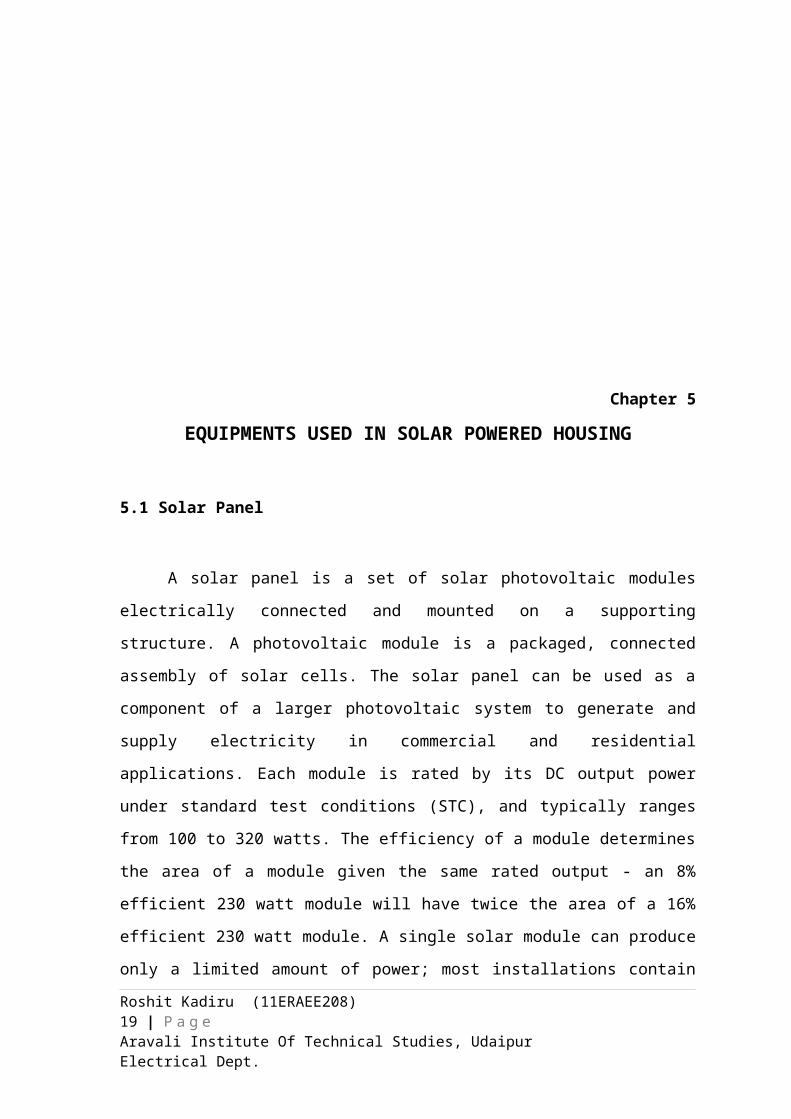
Fig. 5.1 Solar Cell
5.1.1 Construction of Solar Panel
Solar modules use light energy (photons) from the sun to generate electricity
through the photovoltaic effect. The majority of modules use wafer-based crystalline
Roshit Kadiru (11ERAEE208) 13 | P a g eAravali Institute Of Technical Studies, Udaipur Electrical Dept.
silicon cells or thin-film cells based on cadmium telluride or silicon. The structural (load
carrying) member of a module can either be the top layer or the back layer. Cells must
also be protected from mechanical damage and moisture. Most solar modules are rigid,
but semi-flexible ones are available, based on thin-film cells. These early solar modules
were first used in space in 1958.
Electrical connections are made in series to achieve a desired output voltage
and/or in parallel to provide a desired current capability. The conducting wires that take
the current off the modules may contain silver, copper or other non-magnetic conductive
transition metals. The cells must be connected electrically to one another and to the rest of
the system. Externally, popular terrestrial usage photovoltaic modules use MC3 (older) or
MC4 connectors to facilitate easy weatherproof connections to the rest of the system.
Bypass diodes may be incorporated or used externally, in case of partial module shading,
to maximize the output of module sections still illuminated.
Some recent solar module designs include concentrators in which light is focused
by lenses or mirrors onto an array of smaller cells. This enables the use of cells with a
high cost per unit area in a cost-effective way.
5.1.2 Efficiency of Solar Panel
Depending on construction, photovoltaic modules can produce electricity from a
range of frequencies of light, but usually cannot cover the entire solar range (specifically,
ultraviolet, infrared and low or diffused light). Hence much of the incident sunlight
energy is wasted by solar modules, and they can give far higher efficiencies if illuminated
with monochromatic light. Therefore, another design concept is to split the light into
different wavelength ranges and direct the beams onto different cells tuned to those
ranges.[citation needed] This has been projected to be capable of raising efficiency by
50%.
A research by Imperial College, London has shown that the efficiency of a solar
panel can be improved by studding the light-receiving semiconductor surface with
aluminium nano-cylinders similar to the ridges on Lego blocks. The scattered light then
travels along a longer path in the semiconductor which meant that more photons could be
absorbed and converted into current. Although these nano-cylinders were used previously
in which aluminium was preceded by gold and silver, the light scattering occurred in the
near infrared region and visible light was absorbed strongly. Aluminium was found to
Roshit Kadiru (11ERAEE208) 14 | P a g eAravali Institute Of Technical Studies, Udaipur Electrical Dept.
have absorbed ultraviolet part of the spectrum and the visible and near infrared parts of
the spectrum were found to be scattered by the aluminium surface. This, the research
argued, could bring down the cost significantly and improve the efficiency as aluminium
is more abundant and less costly than gold and silver. The research also noted that the
increase in current makes thinner film solar panels technically feasible without
compromising power conversion efficiencies, thus reducing material consumption.
5.2 Inverter
A power inverter, or inverter, is an electronic device or circuitry that changes
direct current (DC) to alternating current (AC). The input voltage, output voltage and
frequency, and overall power handling, are dependent on the design of the specific device
or circuitry.
A power inverter can be entirely electronic or may be a combination of
mechanical effects (such as a rotary apparatus) and electronic circuitry. Static inverters do
not use moving parts in the conversion process.
Typical applications for power inverters include:
Portable consumer devices that allow the user to connect a battery, or set of
batteries, to the device to produce AC power to run various electrical items such
as lights, televisions, kitchen appliances, and power tools.
Use in power generation systems such as electric utility companies or solar
generating systems to convert DC power to AC power.
Use within any larger electronic system where an engineering need exists for
deriving an AC source from a DC source.
5.2.1 Input of Inverter
A typical power inverter device or circuit will require a relatively stable DC
power source capable of supplying enough current for the intended overall power
handling of the inverter. Possible DC power sources include: rechargeable batteries, DC
power supplies operating off of the power company line, and solar cells. The inverter
does not produce any power, the power is provided by the DC source. The inverter
translates the form of the power from direct current to an alternating current waveform.
Roshit Kadiru (11ERAEE208) 15 | P a g eAravali Institute Of Technical Studies, Udaipur Electrical Dept.
The level of the needed input voltage depends entirely on the design and purpose
of the inverter. In many smaller consumer and commercial inverters a 12V DC input is
popular because of the wide availability of powerful rechargeable 12V lead acid batteries
which can be used as the DC power source.
5.2.2 Output Waveform
An inverter can produce square wave, modified sine wave, pulsed sine
wave, or sine wave depending on circuit design. The two dominant commercialized
waveform types of inverters as of 2007 are modified sine wave and sine wave.
There are two basic designs for producing household plug-in voltage from a
lower-voltage DC source, the first of which uses a switching boost converter to produce a
higher-voltage DC and then converts to AC. The second method converts DC to AC at
battery level and uses a line-frequency transformer to create the output voltage.
5.2.2.1 Sine wave
A power inverter device which produces a smooth sinusoidal AC waveform is
referred to as a sine wave inverter. To more clearly distinguish from "modified sine
wave" or other creative terminology, the phrase pure sine wave inverter is sometimes
used.
In situations involving power inverter devices which substitute for standard line
power, a sine wave output is extremely desirable because the vast majority of electric
plug in products and appliances are engineered to work well with the standard electric
utility power which is a true sine wave.
At present, sine wave inverters tend to be more complex and have significantly
higher cost than a modified sine wave type of the same power handling.
Fig. 5.2 Sine Wave
Roshit Kadiru (11ERAEE208) 16 | P a g eAravali Institute Of Technical Studies, Udaipur Electrical Dept.
5.2.2.2 Modified sine wave
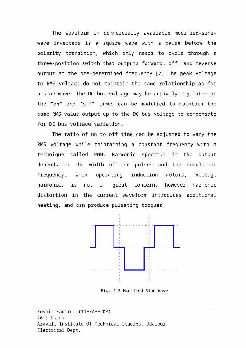
The terminology "modified sine wave" has come into use and refers to an
output waveform that is a useful rough approximation of a sine wave for power
translation purposes.
The waveform in commercially available modified-sine-wave inverters is a square
wave with a pause before the polarity transition, which only needs to cycle through a
three-position switch that outputs forward, off, and reverse output at the pre-determined
frequency.[2] The peak voltage to RMS voltage do not maintain the same relationship as
for a sine wave. The DC bus voltage may be actively regulated or the "on" and "off"
times can be modified to maintain the same RMS value output up to the DC bus voltage
to compensate for DC bus voltage variation.
The ratio of on to off time can be adjusted to vary the RMS voltage while
maintaining a constant frequency with a technique called PWM. Harmonic spectrum in
the output depends on the width of the pulses and the modulation frequency. When
operating induction motors, voltage harmonics is not of great concern, however harmonic
distortion in the current waveform introduces additional heating, and can produce
pulsating torques.
Fig. 5.3 Modified Sine Wave
Numerous electric equipment will operate quite well on modified sine wave
power inverter devices, especially any load that is resistive in nature such as a traditional
incandescent light bulb.
Most AC motors will run on MSW inverters with an efficiency reduction of about
20% due to the harmonic content.
Roshit Kadiru (11ERAEE208) 17 | P a g eAravali Institute Of Technical Studies, Udaipur Electrical Dept.
5.3 Battery (For Off Grid System)
The lead–acid battery was invented in 1859 by French physicist Gaston Planté and
is the oldest type of rechargeable battery. Despite having a very low energy-to-weight
ratio and a low energy-to-volume ratio, its ability to supply high surge currents means
that the cells have a relatively large power-to-weight ratio. These features, along with
their low cost, make it attractive for use in motor vehicles to provide the high current
required by automobile starter motors.
As they are inexpensive compared to newer technologies, lead-acid batteries are
widely used even when surge current is not important and other designs could provide
higher energy densities. Large-format lead-acid designs are widely used for storage in
backup power supplies in cell phone towers, high-availability settings like hospitals, and
stand-alone power systems. For these roles, modified versions of the standard cell may be
used to improve storage times and reduce maintenance requirements. Gel-cells and
absorbed glass-mat batteries are common in these roles, collectively known as VRLA
(valve-regulated lead-acid) batteries.
During the 1970s researchers developed the sealed version of "gel battery", which
mixes a silica gelling agent into the electrolyte (Silica gel based lead Acid batteries used
in Portable Radios from early 1930s were not fully sealed). This converts the formerly
liquid interior of the cells into a semi-stiff paste, providing many of the same advantages
of the AGM. Such designs are even less susceptible to evaporation and are often used in
situations where little or no periodic maintenance is possible. Gel cells also have lower
freezing and higher boiling points than the liquid electrolytes used in conventional wet
cells and AGMs, which makes them suitable for use in extreme conditions.
The only downside to the gel design is that the gel prevents rapid motion of the
ions in the electrolyte, which reduces carrier mobility and thus surge current capability.
For this reason, gel cells are most commonly found in energy storage applications like
off-grid systems.
Both gel and AGM designs are sealed, do not requiring watering, can be used in
any orientation, and use a valve for gas blowoff. For this reason, both designs can be
called maintenance free, sealed and VRLA. However, it is quite common to find
resources stating that these terms refer to one or another of these designs, specifically
Roshit Kadiru (11ERAEE208) 18 | P a g eAravali Institute Of Technical Studies, Udaipur Electrical Dept.
5.3.1 Deep cycle batteries
Specially designed deep-cycle cells are much less susceptible to degradation due
to cycling, and are required for applications where the batteries are regularly discharged,
such as photovoltaic systems, electric vehicles (forklift, golf cart, electric cars and other)
and uninterruptible power supplies. These batteries have thicker plates that can deliver
less peak current, but can withstand frequent discharging.
A deep-cycle battery is designed to discharge between 45% and 75% of its
capacity, depending on the manufacturer and the construction of the battery. Although
these batteries can be cycled down to 20% charge, the best lifespan versus cost method is
to keep the average cycle at about 45% discharge. There is a direct correlation between
the depth of discharge of the battery, and the number of charge and discharge cycles it
can perform.
5.3.2 Battery Connections
The first thing you need to know is that there are 2 ways to successfully connect
two or more batteries. The first is Series and the second is parallel
5.3.2.1 Series Connection
Series adds the voltage of the two batteries, but keeps the same amperage rating
(also known as Amp Hours). For example, these two 6 Volt batteries joined in series now
produce 12 Volts, but still have a total capacity of 10 Amps. To connect batteries in a
series, use a jumper wire to connect the negative terminal of the first battery to the
positive terminal of the second battery. Use another set of cables to connect the open
positive and negative terminals to your application.
Fig. 5.4 Series Connection
Roshit Kadiru (11ERAEE208) 19 | P a g eAravali Institute Of Technical Studies, Udaipur Electrical Dept.
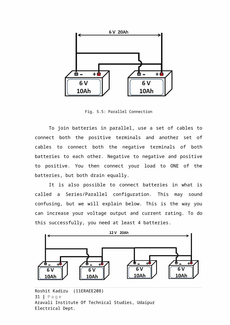
5.3.2.2 Parallel Connection
Parallel connections will increase your current rating, but the voltage will stay the
same. In the diagram to the left, we're back to 6 Volts, but the Amps increase to 20. It's
important to note that because the amperage of the batteries increased, you may need a
heavier duty cable to avoid the cables burning out.
Fig. 5.5: Parallel Connection
To join batteries in parallel, use a set of cables to connect both the positive
terminals and another set of cables to connect both the negative terminals of both batteries
to each other. Negative to negative and positive to positive. You then connect your load
to ONE of the batteries, but both drain equally.
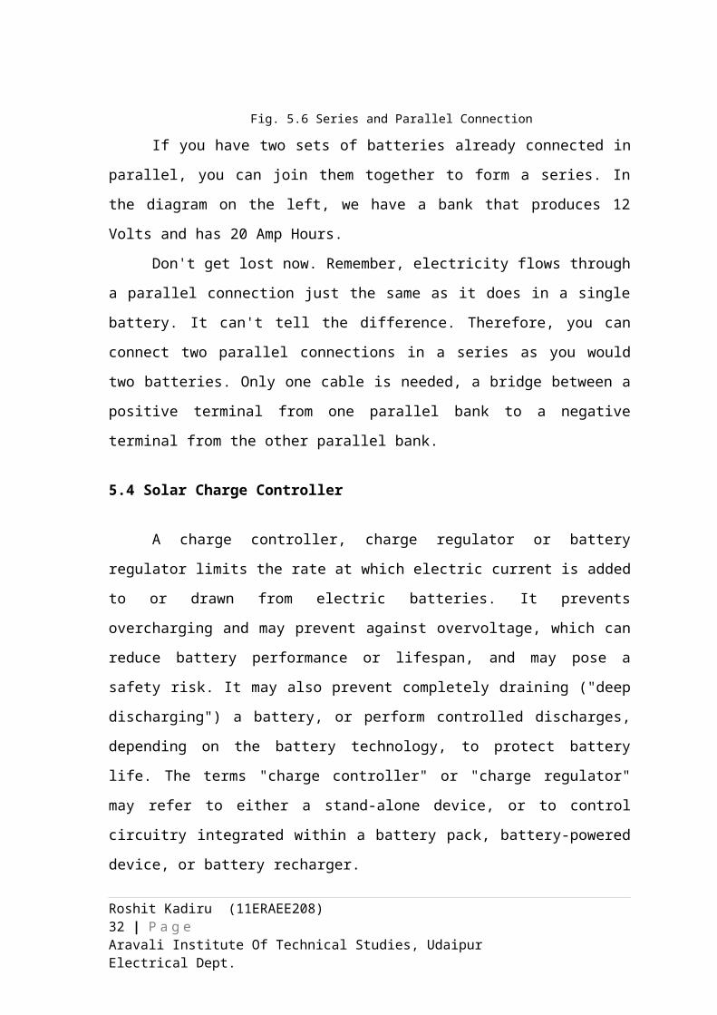
It is also possible to connect batteries in what is called a Series/Parallel
configuration. This may sound confusing, but we will explain below. This is the way you
can increase your voltage output and current rating. To do this successfully, you need at
least 4 batteries.
Fig. 5.6 Series and Parallel Connection
Roshit Kadiru (11ERAEE208) 20 | P a g eAravali Institute Of Technical Studies, Udaipur Electrical Dept.
If you have two sets of batteries already connected in parallel, you can join them
together to form a series. In the diagram on the left, we have a bank that produces 12
Volts and has 20 Amp Hours.
Don't get lost now. Remember, electricity flows through a parallel connection just
the same as it does in a single battery. It can't tell the difference. Therefore, you can
connect two parallel connections in a series as you would two batteries. Only one cable is
needed, a bridge between a positive terminal from one parallel bank to a negative
terminal from the other parallel bank.
5.4 Solar Charge Controller
A charge controller, charge regulator or battery regulator limits the rate at which
electric current is added to or drawn from electric batteries. It prevents overcharging and
may prevent against overvoltage, which can reduce battery performance or lifespan, and
may pose a safety risk. It may also prevent completely draining ("deep discharging") a
battery, or perform controlled discharges, depending on the battery technology, to protect
battery life. The terms "charge controller" or "charge regulator" may refer to either a
stand-alone device, or to control circuitry integrated within a battery pack, battery-
powered device, or battery recharger.
In solar applications, charge controllers may also be called solar regulators. Some
charge controllers / solar regulators have additional features, such as a low voltage
disconnect (LDV), a separate circuit which powers down the load when the batteries
become overly discharged (some battery chemistries are such that over-discharge can ruin
the battery).
A series charge controller or series regulator disables further current flow into
batteries when they are full. A shunt charge controller or shunt regulator diverts excess
electricity to an auxiliary or "shunt" load, such as an electric water heater, when batteries
are full.
Simple charge controllers stop charging a battery when they exceed a set high
voltage level, and re-enable charging when battery voltage drops back below that level.
Pulse width modulation (PWM) and maximum power point tracker (MPPT) technologies
are more electronically sophisticated, adjusting charging rates depending on the battery's
level, to allow charging closer to its maximum capacity.
Roshit Kadiru (11ERAEE208) 21 | P a g eAravali Institute Of Technical Studies, Udaipur Electrical Dept.
Charge controllers may also monitor battery temperature to prevent overheating.
Some charge controller systems also display data, transmit data to remote displays, and
data logging to track electric flow over time.
5.5 Bi-directional Meter (Net Metering – For Grid Tie system)
While you're away, your house is generating energy but you're not using it.
Meanwhile at night, when you have the lights and TV blaring, your solar system is sitting
idle. You could buy an expensive battery to store the extra energy you generate during the
day, but there's another option that allows you to send your extra power to the grid in
exchange for banked energy credit that you can use when you need it. It's called net
metering.
When your home is equipped with a renewable energy source, it sends the excess
energy that's generated back into the grid to power other homes. An electrical converter
called an inverter turns the DC (direct current) power coming from your renewable
energy source into AC (alternating current) power, which matches the voltage of the
electricity flowing through the power line. As that excess energy is being generated, your
power meter spins backward rather than forward, giving you a credit that you can use to
pay for your future energy use.
If you've generated more energy than you've used at the end of the year, your
electric company may pay you back for the extra power at the retail rate. If you have
market-rate net metering, the utility company will pay only a wholesale rate, which is less
than retail and won't earn you anything (it's kind of like giving away your extra energy),
but you'll still save on your overall power bill.
Net metering can be measured over the month or year. Annualized net metering
provides a more accurate measurement because it takes into account your changing
energy usage and production over the four seasons.
Roshit Kadiru (11ERAEE208) 22 | P a g eAravali Institute Of Technical Studies, Udaipur Electrical Dept.
Chapter 6
LOAD AND EQUIPMENT RATING CALCULATIONS
6.1 Load Calculation
Items of electrical equipment like light bulbs, computers, and fans, take energy in
the form of electricity, and use it to do useful things for us. Really they're converting the
energy into other forms (heat, motion etc.), but we say that they're "using" it because we
don't really care about what exactly is happening to it, we just want our equipment to
work when we switch it on and stop when we switch it off.
The rate at which these things use energy is their power. Or, depending on the
thing, and the person you're talking to, you might hear it called their "load" or their
"demand", or you might just hear it referred to in terms of a W or kW value.
Light bulbs are a simple example: if you have a 100 W light bulb you know that it
will use 100 W of power when it's running (100 W of power being the same as 0.1 kW of
power). The watts aren't affected by how long the 100 W light bulb is running for... A
second, an hour, a day - no difference - so long as it's switched on it will be using 100 W
of power. If it's not switched on it won't be using any power (i.e. 0 W).
Some equipment is more complicated. Consider a laptop: at any one instant it
might be using 50 W of power, or 30 W of power, or 43 W of power, or any similar such
value. It depends on what it's doing - if it's sitting there doing nothing it'll probably use
less power than if you're hammering away on an Excel spreadsheet, listening to some
music, and burning a DVD, all at the same time.
We make a distinction between instantaneous power and average power:
6.1.1 Instantaneous power
The instantaneous power (or instantaneous demand, or instantaneous load) is the
power that something is using (or generating) at any one moment in time. Put your laptop
on standby and its instantaneous power will drop immediately. Bring it back to life and its
instantaneous power will rise immediately.
If, at any particular moment, everything in an office building is switched on, that
office building might be using 42 kW of power. That's 42 kW of instantaneous power. If,
Roshit Kadiru (11ERAEE208) 23 | P a g eAravali Institute Of Technical Studies, Udaipur Electrical Dept.
at any particular moment, everything in the office building is switched off, that building
should be using 0 kW of power. That's 0 kW of instantaneous power.
The instantaneous power of most buildings varies constantly. People are
constantly switching things on and off, and many items of equipment within the building
have instantaneous power that is constantly changing too.
6.1.2 Average power
The average power represents the power that something uses or generates, on average:
Over a specific period of time (e.g. yesterday); or
Over multiple periods of time (e.g. across all the weekends on record); or
Throughout a certain type of operation (e.g. typical laptop usage, or typical
building usage - Monday to Friday 09:00 to 17:00, or typical efficiency for
something that's generating power).
Remember our example of an office building that uses 42 kW of power when
everything's switched on, and 0 kW of power when everything's switched off? If, on
average, half the things in the office building are switched on, and half are switched off,
then the average power will be around 21 kW overall (21 kW being half of 42 kW).
Or maybe that's just the average power of the office building on weekdays. On
weekends, when people are at home, and most equipment in the building is switched off,
the average power might be lower, maybe 5 or 10 kW.
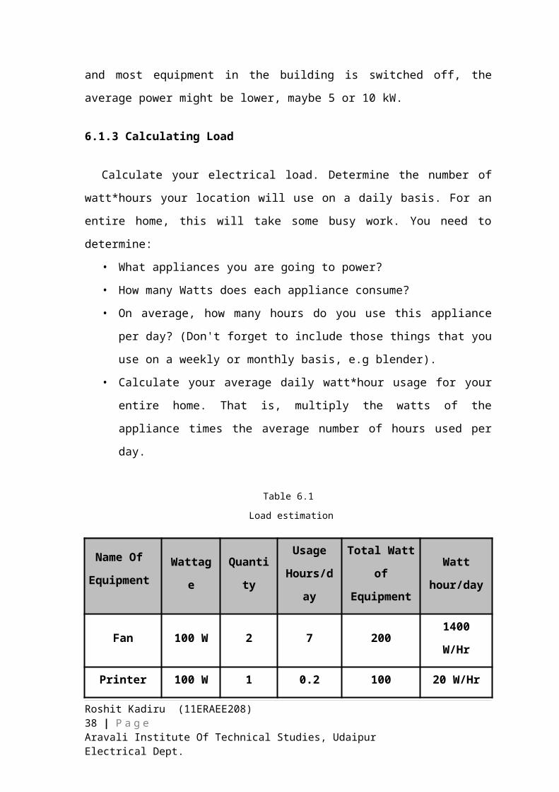
6.1.3 Calculating Load
Calculate your electrical load. Determine the number of watt*hours your location will
use on a daily basis. For an entire home, this will take some busy work. You need to
determine:
• What appliances you are going to power?
• How many Watts does each appliance consume?
• On average, how many hours do you use this appliance per day? (Don't forget to
include those things that you use on a weekly or monthly basis, e.g blender).
• Calculate your average daily watt*hour usage for your entire home. That is,
multiply the watts of the appliance times the average number of hours used per
day.
Roshit Kadiru (11ERAEE208) 24 | P a g eAravali Institute Of Technical Studies, Udaipur Electrical Dept.
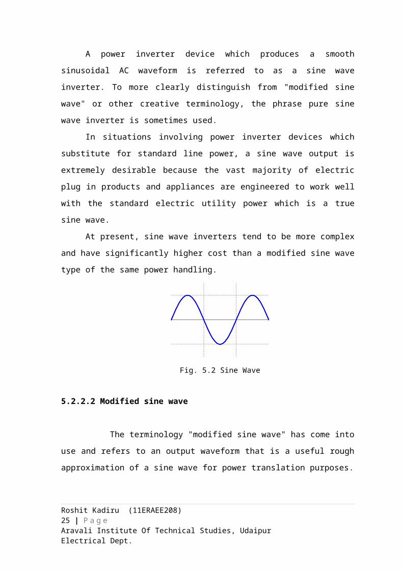
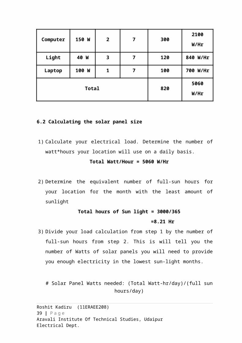
Table 6.1
Load estimation
Name Of
Equipment Wattage QuantityUsage
Hours/day
Total Watt of
Equipment
Watt
hour/day
Fan 100 W 2 7 200 1400 W/Hr
Printer 100 W 1 0.2 100 20 W/Hr
Computer 150 W 2 7 300 2100 W/Hr
Light 40 W 3 7 120 840 W/Hr
Laptop 100 W 1 7 100 700 W/Hr
Total 820 5060 W/Hr
6.2 Calculating the solar panel size
1) Calculate your electrical load. Determine the number of watt*hours your location
will use on a daily basis.
Total Watt/Hour = 5060 W/Hr
2) Determine the equivalent number of full-sun hours for your location for the month
with the least amount of sunlight
Total hours of Sun light = 3000/365
=8.21 Hr
3) Divide your load calculation from step 1 by the number of full-sun hours from step 2.
This is will tell you the number of Watts of solar panels you will need to provide you
enough electricity in the lowest sun-light months.
# Solar Panel Watts needed: (Total Watt-hr/day)/(full sun hours/day)
Size of Solar Panel = 5060/8.21 = 616 Watt
Roshit Kadiru (11ERAEE208) 25 | P a g eAravali Institute Of Technical Studies, Udaipur Electrical Dept.
4) Compensate for system inefficiencies. Every part of a solar powered system has some inefficiency in it. The rule of thumb is if you are going to use an inverter (to produce AC) your total system inefficiency will be 30%. For systems that will be using the DC voltage directly from the battery bank, the inefficiency factor is 20%. So, to compensate for inefficiencies multiply your answer to step 3 by 1.3 (or 1.2, if there's no inverter). This answer is the number of watts of solar panels you will need to provide enough electricity for your loads.
New size of solar panel = 616 * 1.3
= 800 W
5) Finally, to determine how many solar panels you will need, take your answer from
step 4 and divide it by the rated power output (watts) of the solar panel that you have
chosen.
Total No. of Solar Panels Needed = (Total Solar Panel Watts Needed)/(Solar Panel
Rated output)
No. of Solar Panel needed = 800/200
= 4 Panels
6.3 Battery Size Calculation
The first thing you have to decide on is if you are going to use a 12V, 24V or 48V
DC system (these are the most common selections). The advantages to using a larger DC
voltage system is that the wires/cabling you will need to use can be of a smaller gauge
(smaller diameter). Systems with higher DC voltages lose less energy due to resistances
in wiring that those of lower DC voltage (e.g. 12V).
The downside to higher voltage systems is that you have to buy everything in sets,
and it may increase your overall cost. For instance, a 24V system will require you to buy
solar panels in sets of 2 (assuming each panel produces 12V -> 12V+12V=24V). In the
case of batteries, if you plan to use 6V batteries you have to buy them in sets of four (4 x
6V = 24V) to match the system voltage.
Another downside to higher voltage systems, is that the voltage levels become
more dangerous as they get higher. Whereas, 12V systems are less likely to seriously
harm you.
Roshit Kadiru (11ERAEE208) 26 | P a g eAravali Institute Of Technical Studies, Udaipur Electrical Dept.
An advantage to 12V system is that it's a bit easier to find equipment you can
power directly off of the batteries (i.e. 12V). Whereas if you were to power 12V
appliances off of a 48V system, you would need to also buy a DC voltage converter.
6.3.1 Steps to Decide the Battery Size
1. Decide the voltage of the battery.
2. Determine the total watt hours you will be using per day. = 5060 WHr
3. Determine the Days of autonomy. (Means decide the no. of days you want your
battery to support your electrical systems) = 1
4. Multiply the number of watt*hours from your load calculation (Step 2) by the
number of storage days (Step 3).
= 5060 * 1 = 5060 W
5. Determine how deeply you want to discharge your batteries. 80% is considered
the maximum amount you can discharge your lead-acid battery array, whereas
50% is an optimal amount for battery longevity. Then divide the amount
calculated in Step 4 by 0.80 or 0.50.
= 5060/0.8
= 6325 WHr
6. Find the watt hour capacity of the battery you selected. This is the voltage of the
battery times the ampere hour capacity. For example, the PVX-4050HT Solar
Battery is a 6V, 266 Ah battery. So it's Watt*Hour capacity is: 6Vx266Ah = 1596
WHr.
7. Determine the number of batteries you need (almost). Divide the value you
calculated for Step 5 by the value you found for Step 6.
Example: 6325/1596= 4 Batteries
8. Round the number of batteries to fit the system voltage you selected. For instance,
a 12V system will require that you use 6V batteries in sets of 2, or a 24V system
will require 6V batteries to be used in sets of four. , if you are planning to have a
12V system and your calculations from Step 8 give you 5 batteries, you must
round that number up to 6 batteries.
6.4 Inverter Size Calculation
To determine the inverter size we must find the peak load or maximum wattage of
your home. This is found by adding up the wattage of the appliances and devices that
Roshit Kadiru (11ERAEE208) 27 | P a g eAravali Institute Of Technical Studies, Udaipur Electrical Dept.
could be run at the same time. Include everything from microwaves and lights to
computers and clocks. The sum will tell you which inverter size you need.
Table 6.1
Load estimation for inverter size
Name Of Equipment
Wattage Quantity Total equipment watt
Fan 100 W 2 200 W
Printer 100 W 1 100 W
Computer 150 W 2 300 W
Light 40 W 3 120 W
Laptop 100 W 1 100 W
Total Watt 820 W
6.5 Charge Controller Rating Calculation
Once you have sized your battery bank and solar panel array, determining which
charge controller to use is comparatively straight forward. All we have to do is find the
current through the controller by using power = voltage x current. Take the power
produced by the solar panels and divide by the voltage of the batteries.
Example: Our solar array is producing 800 W and charging battery bank is of 12 V.
Then the controller size will be = 800/12
= 67 A
Now multiply the value of safety factor 1.25 with the value of size controller
= 67 * 1.25
= 84 A
Chapter 7
OPTIMUM TILT OF SOLAR PANELS
To get the most from solar panels, you need to point them in the direction that
captures the most sun. But there are a number of variables in figuring out the best
Roshit Kadiru (11ERAEE208) 28 | P a g eAravali Institute Of Technical Studies, Udaipur Electrical Dept.
direction. This page is designed to help you find the best placement for your solar panels
in your situation.
This advice applies to any type of panel that gets energy from the sun;
photovoltaic, solar hot water, etc. We assume that the panel is fixed, or has a tilt that can
be adjusted seasonally. (Panels that track the movement of the sun throughout the day can
receive 10% (in winter) to 40% (in summer) more energy than fixed panels. This page
doesn’t discuss tracking panels.)
Solar panels should always face true south if you are in the northern hemisphere,
or true north if you are in the southern hemisphere. True north is not the same as magnetic
north. If you are using a compass to orient your panels, you need to correct for the
difference, which varies from place to place. Search the web for “magnetic declination”
to find the correction for your location.
The next question is, at what angle from horizontal should the panels be tilted?
Books and articles on solar energy often give the advice that the tilt should be equal to
your latitude, plus 15 degrees in winter or minus 15 degrees in summer. It turns out that
you can do better than this - about 4% better.
It is simplest to mount your solar panels at a fixed tilt and just leave them there.
But because the sun is higher in the summer and lower in the winter, you can capture
more energy during the whole year by adjusting the tilt of the panels according to the
season. The following table shows the effect of adjusting the angle, using a system at 40°
latitude as an example. (The comparison would be a little different for different latitudes.)
Each option is compared with the energy received by the best possible tracker that always
keeps the panel pointed directly at the sun.
Table 7.1
Utilization as per season
Fixed Adj. 2 seasons Adj. 4 seasons 2-axis tracker
% of optimum 71.1% 75.2% 75.7% 100%
In short, adjusting the tilt twice a year gives you a meaningful boost in energy.
Adjusting four times a year produces only a little more, but could be important if you
need to optimize production in spring and fall. You can jump to the section on the best
fixed tilt angle, or skip to the sections on two-season or four-season adjusting.
Roshit Kadiru (11ERAEE208) 29 | P a g eAravali Institute Of Technical Studies, Udaipur Electrical Dept.
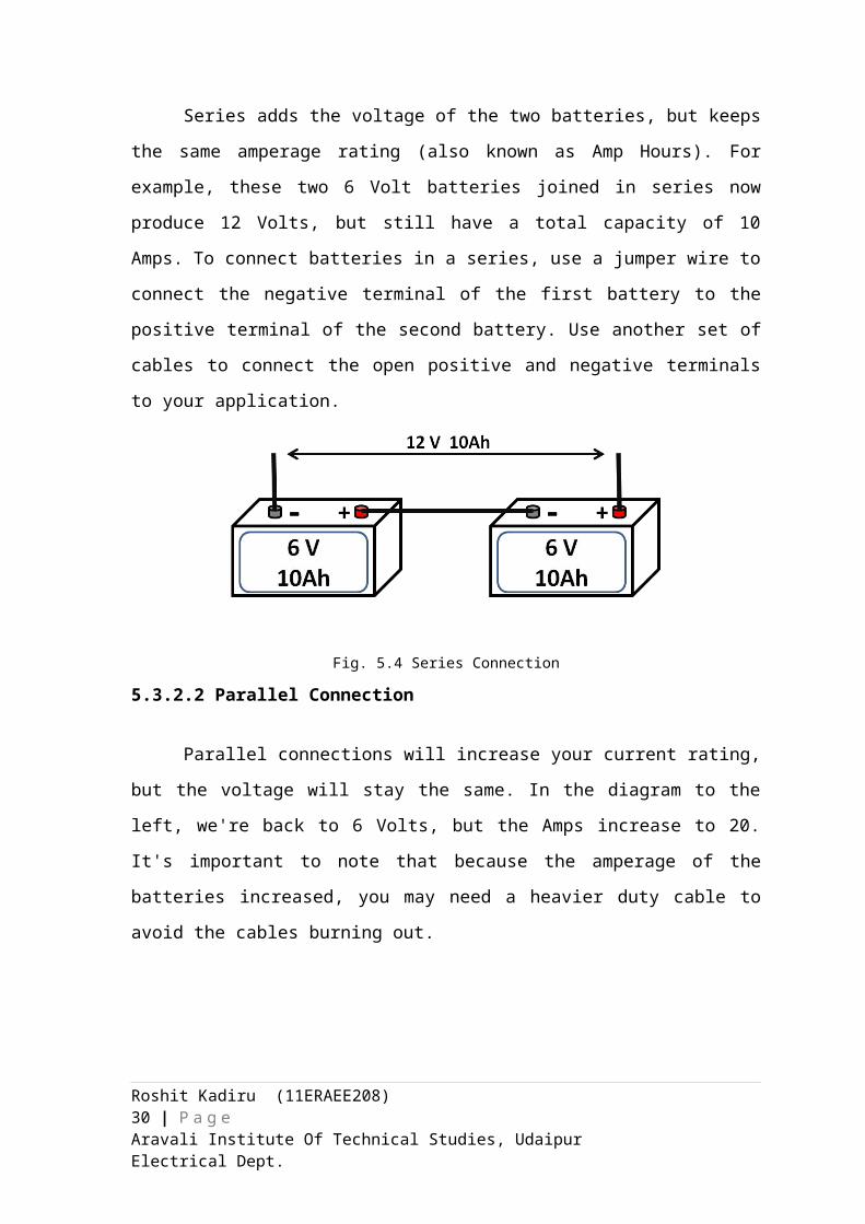
Fig. 7.1 Optimization graph as per season
7.1 Fixed Position
If your solar panels will have a fixed tilt angle, and you want to get the most
energy over the whole year, then this section is for you. A fixed angle is convenient, but
note that there are some disadvantages. As mentioned above, you’ll get less power than if
you adjusted the angle. Also, if you live where there is snow, adjusting the panels to a
steeper angle in winter makes it more likely that they will shed snow. A panel covered in
snow produces little or no power.
Use one of these formulas to find the best angle from the horizontal at which the panel
should be tilted:
If your latitude is below 25°, use the latitude times 0.87.
If your latitude is between 25° and 50°, use the latitude, times 0.76, plus 3.1 degrees.
This table gives some examples for different latitudes. It also shows the average
insolation on the panel over the year (in kWh/m2 per day), and the energy received
compared to the best possible tracker.
Table 7.2
Insolation as per tilt angle
Latitude Full year angle Avg. insolation on panel % of optimum
Roshit Kadiru (11ERAEE208) 30 | P a g eAravali Institute Of Technical Studies, Udaipur Electrical Dept.
0° 0.0 6.5 72%
5° 4.4 6.5 72%
10° 8.7 6.5 72%
15° 13.1 6.4 72%
20° 17.4 6.3 72%
25° 22.1 6.2 72%
30° 25.9 6.1 71%
35° 29.7 6.0 71%
40° 33.5 5.7 71%
45° 37.3 5.4 71%
50° 41.1 5.1 70%
7.2 Adjusting the tilt twice a year
If you are going to adjust the tilt of your solar panels twice a year, and you want to
get the most energy over the whole year, then this section is for you.
If your latitude is between 25° and 50°, then the best tilt angle for summer is the
latitude, times 0.93, minus 21 degrees. The best tilt angle for winter is the latitude, times
0.875, plus 19.2 degrees. This table gives some examples
Table 7.3
Optimization as per Latitude
LatitudeSummer
angleWinter angle
Average isolation on panel
% of optimum
25° 2.3 41.1 6.6 76%
30° 6.9 45.5 6.4 76%
35° 11.6 49.8 6.2 76%
40° 16.2 54.2 6.0 75%
45° 20.9 58.6 5.7 75%
Roshit Kadiru (11ERAEE208) 31 | P a g eAravali Institute Of Technical Studies, Udaipur Electrical Dept.
50° 25.5 63.0 5.3 74%
7.3 Adjusting the tilt four times a year
If you are going to adjust the tilt of your solar panels four times a year, and you
want to get the most energy over the whole year, then this section is for you. This would
be your situation if you are connected to the grid and can use or sell all the power you
produce.
If your latitude is between 25° and 50°, then the best tilt angles are:
For summer, take the latitude, multiply by 0.92, and subtract 24.3 degrees.
For spring and autumn, take the latitude, multiply by 0.98, and subtract 2.3
degrees.
For winter, take the latitude, multiply by 0.89, and add 24 degrees
If you want to adjust the tilt of your panels four times a year, you can use these figures to
keep capturing the most energy year-round.
Table 7.4
Tilt angle as per Seasons
Latitude Summer angle Spring/autumn angle Winter angle
25° -1.3 22.2 46.3
30° 3.3 27.1 50.7
35° 7.9 32.0 55.2
40° 12.5 36.9 59.6
45° 17.1 41.8 64.1
50° 21.7 46.7 68.5
In winter, a panel fixed at the winter angle will be relatively efficient, capturing 81
to 88 percent of the energy compared to optimum tracking. In the spring, summer, and
Roshit Kadiru (11ERAEE208) 32 | P a g eAravali Institute Of Technical Studies, Udaipur Electrical Dept.
autumn, the efficiency is lower (74-75% in spring/autumn, and 68-74% in summer),
because in these seasons the sun travels a larger area of the sky, and a fixed panel can’t
capture as much of it. These are the seasons in which tracking systems give the most
benefit.
Note that the winter angle is about 5° steeper than what has been commonly
recommended. The reason is that in the winter, most of the solar energy comes at midday,
so the panel should be pointed almost directly at the sun at noon. The angle is fine-tuned
to gather the most total energy throughout the day.
The summer angles are about 12 degrees flatter than is usually recommended. In
fact, at 25° latitude in summer, the panel should actually be tilted slightly away from the
equator.
7.4 Solar Panel Angle Calculation
If you live in the northern hemisphere, you would point your panels due south. If
you live in southern hemisphere, your panels should be pointed north. Most homeowners
with solar energy systems mount their panels in a fixed position, where the panels can be
manually tilted as needed (for example, they can be adjusted seasonally). Here's how to
calculate the best angle for your solar panels:
The quick and easy (but less effective) way: take your latitude and add 15
degrees for the winter, or subtract 15 degrees for the summer.
For example: if your latitude is 40 degrees, the angle you want to tilt your panels
in the winter is: 40 + 15 = 55 degrees.
In the summer, it would be: 40 - 15 = 25 degrees.
The better way (winter): in the winter months, when there's less sun, take your
latitude, multiply it by 0.9, and then add 29 degrees.
For example: if your latitude is 40 degrees, the angle you want to tilt your panels
in the winter is: (40 * 0.9) + 29 = 65 degrees.
This is about 10 degrees steeper than the "quick and easy" way! It's also more
effective, because you want your panels to be directly facing the sun at mid-day
during those short winter days.
The better way (summer): take your latitude, multiply it by 0.9, and subtract
23.5 degrees.
Roshit Kadiru (11ERAEE208) 33 | P a g eAravali Institute Of Technical Studies, Udaipur Electrical Dept.
For example: if your latitude is 40 degrees, your panels should be tilted at: (40 *
0.9) - 23.5 = 12.5 degrees.
The better way (spring & fall): take your latitude and subtract 2.5 degrees.
For example: if your latitude is 40 degrees, the best tilt for your panels in the
spring & fall is: 40 - 2.5 = 37.5 degrees.
Table 7.5
Optimization as per Latitude
SEASON ANGLE / TILT CALCULATION
Winter (Latitude * 0.9) + 29 degrees
Summer (Latitude * 0.9) - 23.5 degrees
Spring and Fall Latitude - 2.5 degrees
Chapter 8
SOLAR
8.1 Maintenance of Solar Panel
Solar panels generally require very little maintenance since there are no moving
parts. A few times a year, the panels should be inspected for any dirt or debris that may
collect on them. Always make sure you are safety conscious when inspecting panels and
don’t take any needless risks! If your panels are too high up on the roof to see very well
from the ground, use caution with ladders.
For a general cleaning, simply use a standard garden hose to wash the face of the
panels during either the early morning or in the evening. Avoid spraying cold water onto
hot panels or you could risk cracking them!
There are also automated cleaners that work similar to sprinklers, such as the Heliotex
system, which can be programmed to clean your panels as needed - a good choice if you
are in an especially dusty area.
Roshit Kadiru (11ERAEE208) 34 | P a g eAravali Institute Of Technical Studies, Udaipur Electrical Dept.
Professional solar panel cleaners are also in abundance and can come out
periodically to clean them throughout the year. Check local listings for high-rated,
reputable solar panel cleaning companies. This is a better choice for panels that are too
high to reach well with a garden hose or if you want a more thorough cleaning.
8.1.1 Steps to clean solar panels
1. The first thing you want to do is to check with your solar panel manufacturer. They
might have specific recommendations for cleaning.
2. Solar panels can become incredible hot in sunshine. Either clean your solar panels in
the morning/afternoon, or pick a relatively cool day.
3. First try if your garden hose alone does the job. If a lot of dust and dirt has
accumulated you might need to clean more thoroughly.
4. Fill a bucket or spray bottle with warm water and soap – no other special equipment
is needed.
5. Clean the surface of the solar panel with a soft cloth or sponge. You do not have to
clean the wiring underneath.
8.2 Life Span of Solar Panel
Solar panels are increasingly becoming popular as a way to use the sun's energy to
conduct electricity which in turn operates equipment in the household or workplace. The
newer solar panel models in the market are expected to have a 40 year lifespan although
they rarely have warranties of more than 20 to 25 years.
With care and attention, solar panels may actually last forty years after installation
although their performance will have deteriorated even if it is not a noticeable
deterioration. The forty year life expectancy goes for both mono-crystalline and
polycrystalline solar panels, and the amount of watts the mono-crystalline or
polycrystalline solar panels produce do not matter; they will still generally have
warranties of up to 25 years and possibly go on to last a lot longer. Some solar panels are
even seen to produce 80% of their initial output after forty years
Roshit Kadiru (11ERAEE208) 35 | P a g eAravali Institute Of Technical Studies, Udaipur Electrical Dept.
Chapter 9
POPULARITY AND NEED OF SOLAR ENERGY
9.1 Why Solar panel is not much used?
Solar power cannot be obtained at night.
Solar cells (or) solar panels are very expensive
Air pollution and whether can affect the production of electricity
They need large area of land to produce more efficient power supply
Due to PV efficiency and low market demand, technological progression is slow.
Large land areas needed to produce energy on a power plant scale
Lack of subsidies and tax credits in India.
Lack of awareness about the benefits of solar energy towards environment.
9.2 Why to use solar power system?
Roshit Kadiru (11ERAEE208) 36 | P a g eAravali Institute Of Technical Studies, Udaipur Electrical Dept.
Solar power reduces your carbon footprint.
As calculated the coal left will last only for 109 years.
According to the IEA Clean Coal Centre, there are over 2300 coal-fired power
stations worldwide as per 2011.
The average household generates 7.4 tons of carbon dioxide per year through
electrical use.
Temperature of the earth has started to increase Since the early 20th century, the
global air and sea surface temperature has increased about 0.8°C (1.4°F)
Due this high emission of carbon dioxide the Glaciers have started melting which
will result in rise of sea level by 23 inches within the next 100 years which in result
will drown many areas of the planet.
CONCLUSION
As of now, I may be able to switch to solar power with a slight gain or slight loss
depending on the amount of size of the solar power and its cost
However, as technology increases, solar prices fall, and electricity prices rise, this may
become a more economical solution.
It also greatly reduce the amount of harmful emissions by using solar power.
Government should introduce more incentives so that the solar powered house gets
more popular among the people.
Government should also give tax benefits to the people using the solar powered house.
Roshit Kadiru (11ERAEE208) 37 | P a g eAravali Institute Of Technical Studies, Udaipur Electrical Dept.
REFRENCES
Wholesale solar - http://www.wholesalesolar.com/gridtie.html
India Solar Energy - http://www.eai.in/ref/ae/sol/sol.html#sthash.2ajthLN6.dpuf
How stuff works –
http://www.howstuffworks.com/environmental/green-science/net-metering.html
CTI Solar sales brochure - http://www.cti-solar.com/userfiles/file/brochlet%20CTI-
SOLAR%20vers%20EN.pdf
SunPower e20 Module –
http://us.sunpowercorp.com/cs/Satellite?blobcol=urldata&blobheader=application
%2Fpdf&blobheadername3=Content-Disposition&blobheadervalue3=attachment
%3B+filename
%3D11_317_sp_e20_327_sf_ds_en_ltr_p.pdf&blobkey=id&blobtable=MungoBlobs&
blobwhere=1300275818929&ssbinary=true
Solar Power world- http://www.solarpowerworldonline.com/top-250-solar-contractors/
Roshit Kadiru (11ERAEE208) 38 | P a g eAravali Institute Of Technical Studies, Udaipur Electrical Dept.
Inverter Technology for the Solar Industry –
http://www.industry.usa.siemens.com/topics/us/en/solarexchange/2009/Documents/
Kerns_Solar_Exchange_Tempe.pdf
Grid-Tied Inverter Safety - http://homepower.com/article/?file=HP130_pg28_ATE_2
Solar PV warranties - http://solarconsumerreporting.webs.com/warranties.html
PV operation and maintenance costs -
http://www1.eere.energy.gov/solar/pdfs/46025.pdf
Inverter Technology for the Solar Industry –
http://www.industry.usa.siemens.com/topics/us/en/solarexchange/2009/Documents/
Kerns_Solar_Exchange_Tempe.pdf
Grid-connected photovoltaic system -
http://www.soe-townsville.org/data/Gridconnected_photovoltaic_systems.pdf
Grid Connected Solar Electric - Photovoltaic (PV) Systems –
http://www.powernaturally.org/programs/solar/PhotoVoltaic.asp?i=1
Roshit Kadiru (11ERAEE208) 39 | P a g eAravali Institute Of Technical Studies, Udaipur Electrical Dept.
Related Documents