USER MANUAL 1.5U Solar Panel

Welcome message from author
This document is posted to help you gain knowledge. Please leave a comment to let me know what you think about it! Share it to your friends and learn new things together.
Transcript
USER MANUAL 1.5U Solar Panel
SOLAR PANELS 1.5U – USER MANUAL
ENDUROSAT 2
1 Change Log ........................................................................................................................ 3
2 Acronyms List ..................................................................................................................... 4
3 Description ......................................................................................................................... 5
4 Product Performance And Properties .................................................................................. 5 4.1 Solar Panels Features And Characteristics ................................................................... 5 4.2 Solar Cell Features And Characteristic .......................................................................... 6
5 Available Configurations ...................................................................................................... 6 5.1 1.5U Solar Panels X/Y .................................................................................................. 7 5.2 1.5U Solar Panels X/Y With RBF .................................................................................. 8
6 Connector Pinout ................................................................................................................ 9 6.1 Connectors Location .................................................................................................... 9
6.1.1 H1 Power Connector ........................................................................................... 10 6.1.2 H2 Power Connector ........................................................................................... 10 6.1.3 H3 Sensors Connector ........................................................................................ 10
6.2 Connector Pinout 1.5u Solar Panel X/Y With RBF ....................................................... 11 6.2.1 Communication Interface Connector .................................................................... 12 6.2.2 RBF Connector .................................................................................................... 12
7 Specifications ................................................................................................................... 13
8 Mechanical Characteristics ............................................................................................... 15 8.1 1.5U Solar Panels X/Y ................................................................................................ 15 8.2 1.5U Solar Panels X/Y With RBF ................................................................................ 17
9 Customization ................................................................................................................... 19
10 Material And Assembling ................................................................................................... 19
11 Included In The Shipment ................................................................................................. 19
12 Handling And Storage ....................................................................................................... 20
13 Warnings .......................................................................................................................... 21
SOLAR PANELS 1.5U – USER MANUAL
ENDUROSAT 3
SOLAR PANEL – 1.5U USER MANUAL
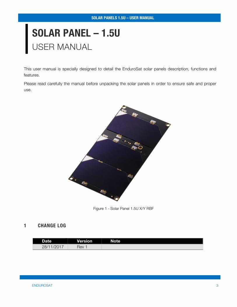
This user manual is specially designed to detail the EnduroSat solar panels description, functions and features.
Please read carefully the manual before unpacking the solar panels in order to ensure safe and proper use.
Figure 1 - Solar Panel 1.5U X/Y RBF
1 CHANGE LOG
Date Version Note 28/11/2017 Rev 1
SOLAR PANELS 1.5U – USER MANUAL
ENDUROSAT 4
2 ACRONYMS LIST
CIE International Commission on Illumination
ECSS European Cooperation Space Standardization
ESA European Space Agency
GEO Geostationary Earth Orbit
GEVS General Environmental Verification Standard
GND Ground
LEO Low Earth Orbit
PCB Printed Circuit Board
RBF Remove Before Flight
RH Relative humidity
SCA Solar Cell Assembly
SPI Serial Peripheral Interface
SOLAR PANELS 1.5U – USER MANUAL
ENDUROSAT 5
3 DESCRIPTION EnduroSat 1.5U Solar Panels are equipped with 3 CESI Solar cells CTJ30 with 29.5% efficiency. The wide effective cell area provides up to 3.6 Watts in LEO per panel.
On the PCB, a network of sensors (Gyroscope, Sun sensor, temperature sensor) and magnetorquer provide inputs and output of the attitude determination and control system. Furthermore, the PCB is equipped with a connector for external magnetorquer.
For bigger CubeSats, multiple panels can be connected in series or in parallel. Also, customization of the panel for external connectors (e.g. remove before flight pin) and interfaces to access the Satellite can be provided upon request.
4 PRODUCT PERFORMANCE AND PROPERTIES 4.1 Solar Panels Features and Characteristics
• CESI Solar Cells CTJ30, space qualified triple junction (specs in the following paragraph); • 90.45cm2 effective cell area (3 solar cells); • Temperature Sensor with SPI Interface (Accuracy: ±1.5°C from -25°C to 85°C (max), ±2.0°C
from -55°C to 125°C (max)); • Up to 3.6 Watt in LEO; • Gold plated invar interconnectors; • Space-grade silicone adhesive with minimum outgassing behavior; • Gyroscope; • Sun Sensor; • Multiple panels can be connected in series or parallel; • Two internal 70µm copper layers; • Plated, countersink mounting holes with ground connection; • Connector for external magnetorquer; • Max Voltage 1: up to 6.99V (3.61W); • Max Voltage 2: up to 4.66V (3.21W); • Max Current 1: up to 517mA; • Max Current 2: up to 688mA;
SOLAR PANELS 1.5U – USER MANUAL
ENDUROSAT 6
4.2 Solar Cell Features and Characteristic
• Efficiency 29.5%; • Triple Junction Solar Cells InGaP/GaAs/Ge; • Polarity N on P; • Very low solar cell mass (81-89 mg/cm2); • Thickness 150 μm ±20 μm; • Fully qualified under ESA Standard ECSS E ST20-08C for LEO and GEO; • External By-pass diode for reverse bias protection; • Size 30.15 cm2; • High Radiation Resistance; • Cover glass; • Good mechanical strength;
5 AVAILABLE CONFIGURATIONS EnduroSat 1.5U Solar Panels are available in 3 configurations.
• 1.5U Solar Panel X/Y • 1.5U Solar Panel X/Y MTQ (with Magnetorquer) • 1.5U Solar Panel X/Y RBF (with Remove Before Flight pin)
All configurations can be ordered with white or black solder mask.
SOLAR PANELS 1.5U – USER MANUAL
ENDUROSAT 7
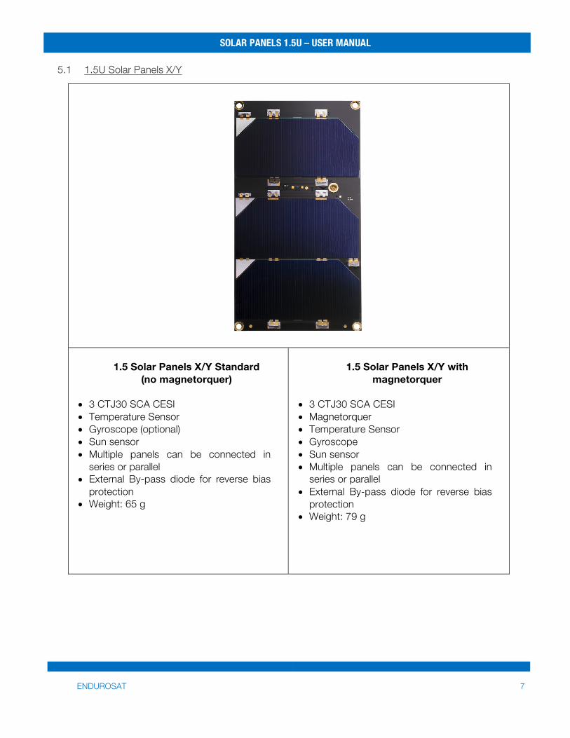
5.1 1.5U Solar Panels X/Y
1.5 Solar Panels X/Y Standard
(no magnetorquer)
• 3 CTJ30 SCA CESI • Temperature Sensor • Gyroscope (optional) • Sun sensor • Multiple panels can be connected in
series or parallel • External By-pass diode for reverse bias
protection • Weight: 65 g
1.5 Solar Panels X/Y with
magnetorquer • 3 CTJ30 SCA CESI • Magnetorquer • Temperature Sensor • Gyroscope • Sun sensor • Multiple panels can be connected in
series or parallel • External By-pass diode for reverse bias
protection • Weight: 79 g
SOLAR PANELS 1.5U – USER MANUAL
ENDUROSAT 8
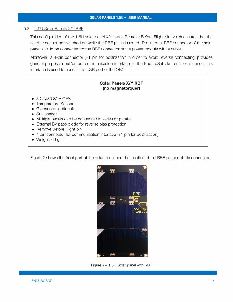
5.2 1.5U Solar Panels X/Y RBF
This configuration of the 1.5U solar panel X/Y has a Remove Before Flight pin which ensures that the satellite cannot be switched on while the RBF pin is inserted. The internal RBF connector of the solar panel should be connected to the RBF connector of the power module with a cable.
Moreover, a 4-pin connector (+1 pin for polarization in order to avoid reverse connecting) provides general purpose input/output communication interface. In the EnduroSat platform, for instance, this interface is used to access the USB port of the OBC.
Solar Panels X/Y RBF
(no magnetorquer)
• 3 CTJ30 SCA CESI • Temperature Sensor • Gyroscope (optional) • Sun sensor • Multiple panels can be connected in series or parallel • External By-pass diode for reverse bias protection • Remove Before Flight pin • 4 pin connector for communication interface (+1 pin for polarization) • Weight: 66 g
Figure 2 shows the front part of the solar panel and the location of the RBF pin and 4-pin connector.
Figure 2 – 1.5U Solar panel with RBF
SOLAR PANELS 1.5U – USER MANUAL
ENDUROSAT 9
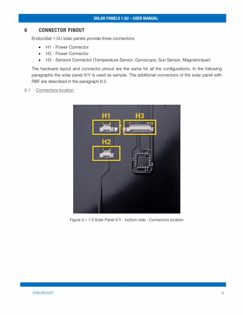
6 CONNECTOR PINOUT EnduroSat 1.5U solar panels provide three connectors:
• H1 - Power Connector • H2 - Power Connector • H3 - Sensors Connector (Temperature Sensor, Gyroscope, Sun Sensor, Magnetorquer)
The hardware layout and connector pinout are the same for all the configurations. In the following paragraphs the solar panel X/Y is used as sample. The additional connectors of the solar panel with RBF are described in the paragraph 6.2.
6.1 Connectors location
Figure 3 – 1.5 Solar Panel X/Y - bottom side - Connectors location
SOLAR PANELS 1.5U – USER MANUAL
ENDUROSAT 10
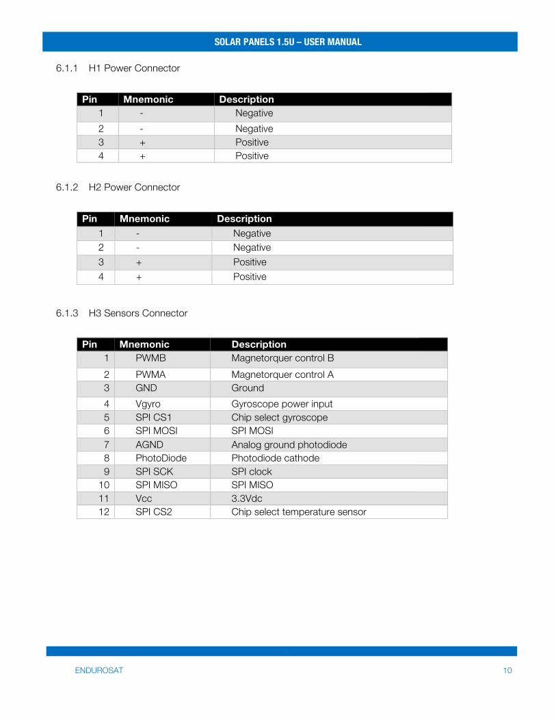
6.1.1 H1 Power Connector
Pin Mnemonic Description 1 - Negative 2 - Negative 3 + Positive 4 + Positive
6.1.2 H2 Power Connector
Pin Mnemonic Description
1 - Negative 2 - Negative 3 + Positive 4 + Positive
6.1.3 H3 Sensors Connector
Pin Mnemonic Description 1 PWMB Magnetorquer control B 2 PWMA Magnetorquer control A 3 GND Ground 4 Vgyro Gyroscope power input 5 SPI CS1 Chip select gyroscope 6 SPI MOSI SPI MOSI 7 AGND Analog ground photodiode 8 PhotoDiode Photodiode cathode 9 SPI SCK SPI clock
10 SPI MISO SPI MISO 11 Vcc 3.3Vdc 12 SPI CS2 Chip select temperature sensor
SOLAR PANELS 1.5U – USER MANUAL
ENDUROSAT 11
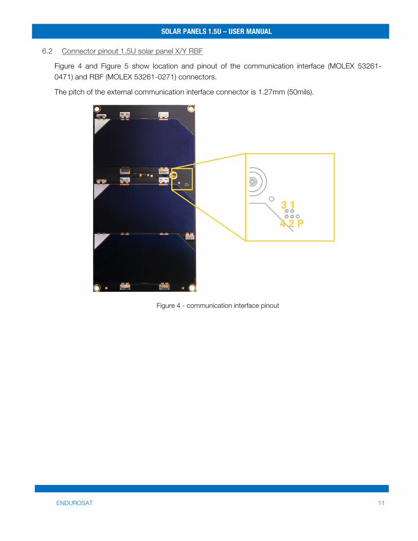
6.2 Connector pinout 1.5U solar panel X/Y RBF
Figure 4 and Figure 5 show location and pinout of the communication interface (MOLEX 53261-0471) and RBF (MOLEX 53261-0271) connectors.
The pitch of the external communication interface connector is 1.27mm (50mils).
Figure 4 - communication interface pinout
SOLAR PANELS 1.5U – USER MANUAL
ENDUROSAT 12
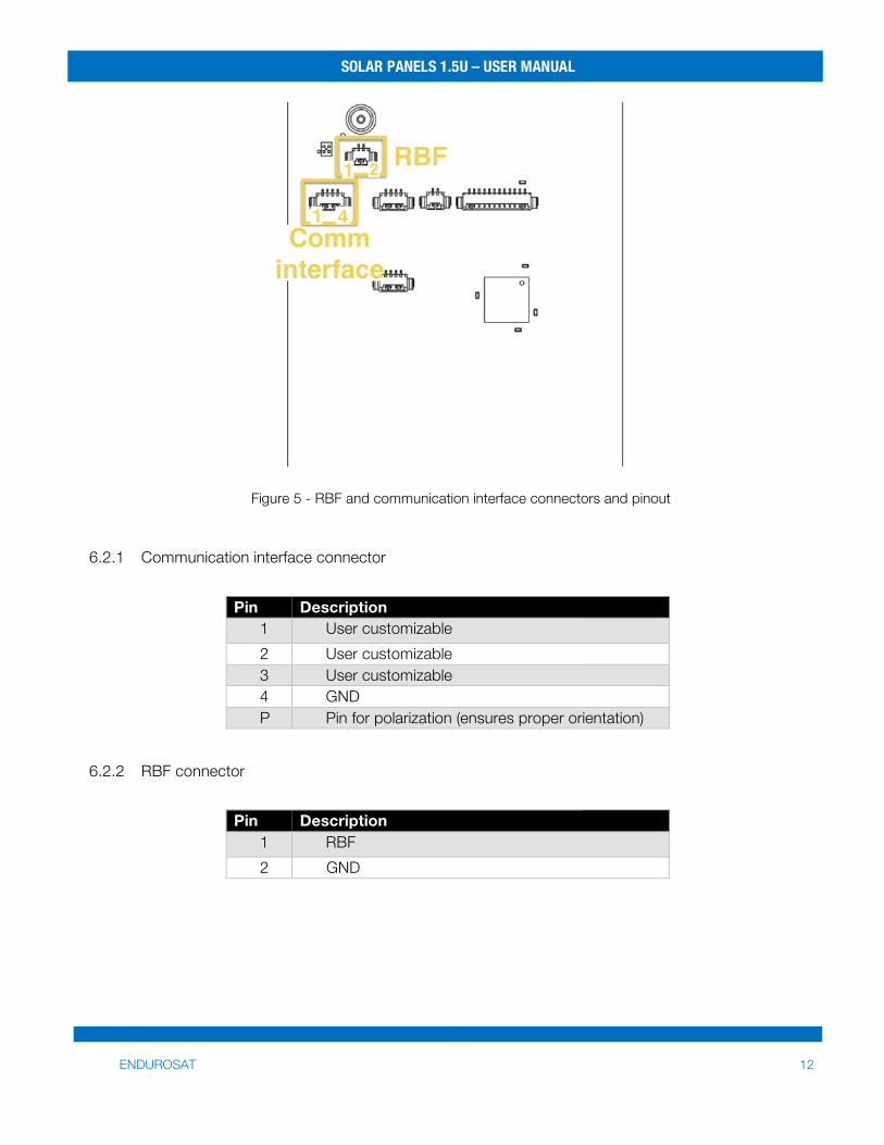
Figure 5 - RBF and communication interface connectors and pinout
6.2.1 Communication interface connector
Pin Description
1 User customizable 2 User customizable 3 User customizable 4 GND P Pin for polarization (ensures proper orientation)
6.2.2 RBF connector
Pin Description 1 RBF 2 GND
SOLAR PANELS 1.5U – USER MANUAL
ENDUROSAT 13
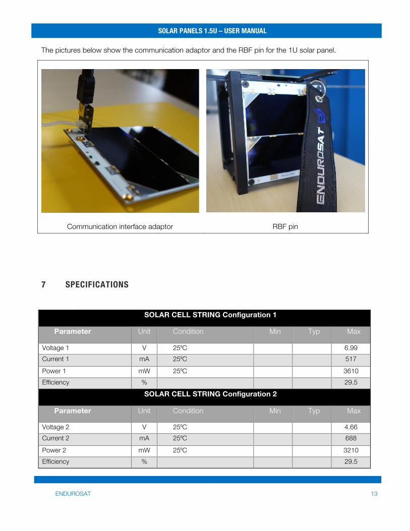
The pictures below show the communication adaptor and the RBF pin for the 1U solar panel.
Communication interface adaptor
RBF pin
7 SPECIFICATIONS
SOLAR CELL STRING Configuration 1
Parameter Unit Condition Min Typ Max
Voltage 1 V 25⁰C 6.99 Current 1 mA 25⁰C 517
Power 1 mW 25⁰C 3610 Efficiency % 29.5
SOLAR CELL STRING Configuration 2
Parameter Unit Condition Min Typ Max
Voltage 2 V 25⁰C 4.66 Current 2 mA 25⁰C 688
Power 2 mW 25⁰C 3210 Efficiency % 29.5
SOLAR PANELS 1.5U – USER MANUAL
ENDUROSAT 14
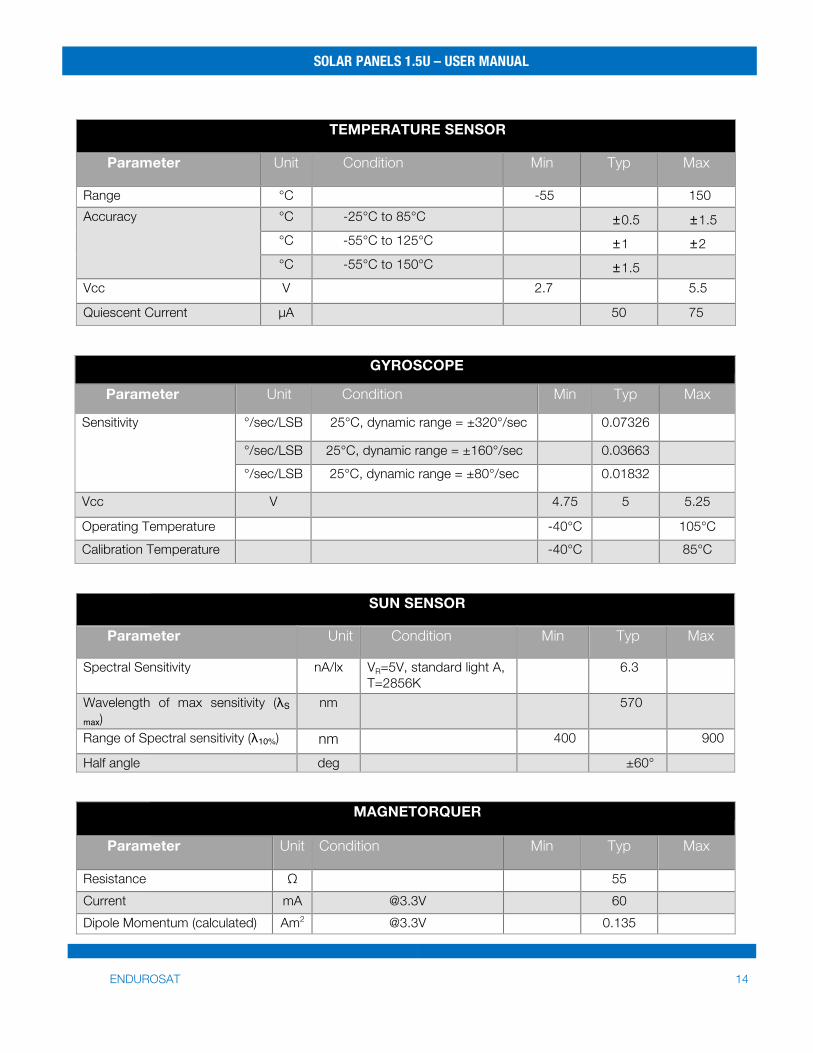
TEMPERATURE SENSOR
Parameter Unit Condition Min Typ Max
Range °C -55 150 Accuracy °C -25°C to 85°C ±0.5 ±1.5
°C -55°C to 125°C ±1 ±2 °C -55°C to 150°C ±1.5
Vcc V 2.7 5.5
Quiescent Current µA 50 75
GYROSCOPE
Parameter Unit Condition Min Typ Max
Sensitivity °/sec/LSB 25°C, dynamic range = ±320°/sec
0.07326
°/sec/LSB 25°C, dynamic range = ±160°/sec 0.03663 °/sec/LSB 25°C, dynamic range = ±80°/sec 0.01832
Vcc V 4.75 5 5.25
Operating Temperature -40°C 105°C Calibration Temperature -40°C 85°C
SUN SENSOR
Parameter Unit Condition Min Typ Max
Spectral Sensitivity nA/lx VR=5V, standard light A, T=2856K
6.3
Wavelength of max sensitivity (λS
max) nm 570
Range of Spectral sensitivity (λ10%) nm 400 900
Half angle deg ±60°
MAGNETORQUER
Parameter Unit Condition Min Typ Max
Resistance Ω 55 Current mA @3.3V 60 Dipole Momentum (calculated) Am2 @3.3V 0.135
SOLAR PANELS 1.5U – USER MANUAL
ENDUROSAT 15
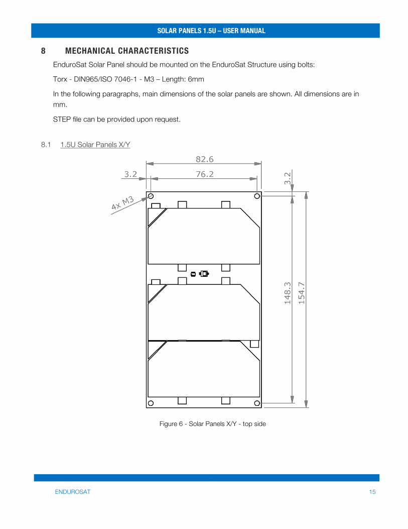
8 MECHANICAL CHARACTERISTICS EnduroSat Solar Panel should be mounted on the EnduroSat Structure using bolts:
Torx - DIN965/ISO 7046-1 - M3 – Length: 6mm
In the following paragraphs, main dimensions of the solar panels are shown. All dimensions are in mm.
STEP file can be provided upon request.
8.1 1.5U Solar Panels X/Y
Figure 6 - Solar Panels X/Y - top side
SOLAR PANELS 1.5U – USER MANUAL
ENDUROSAT 16
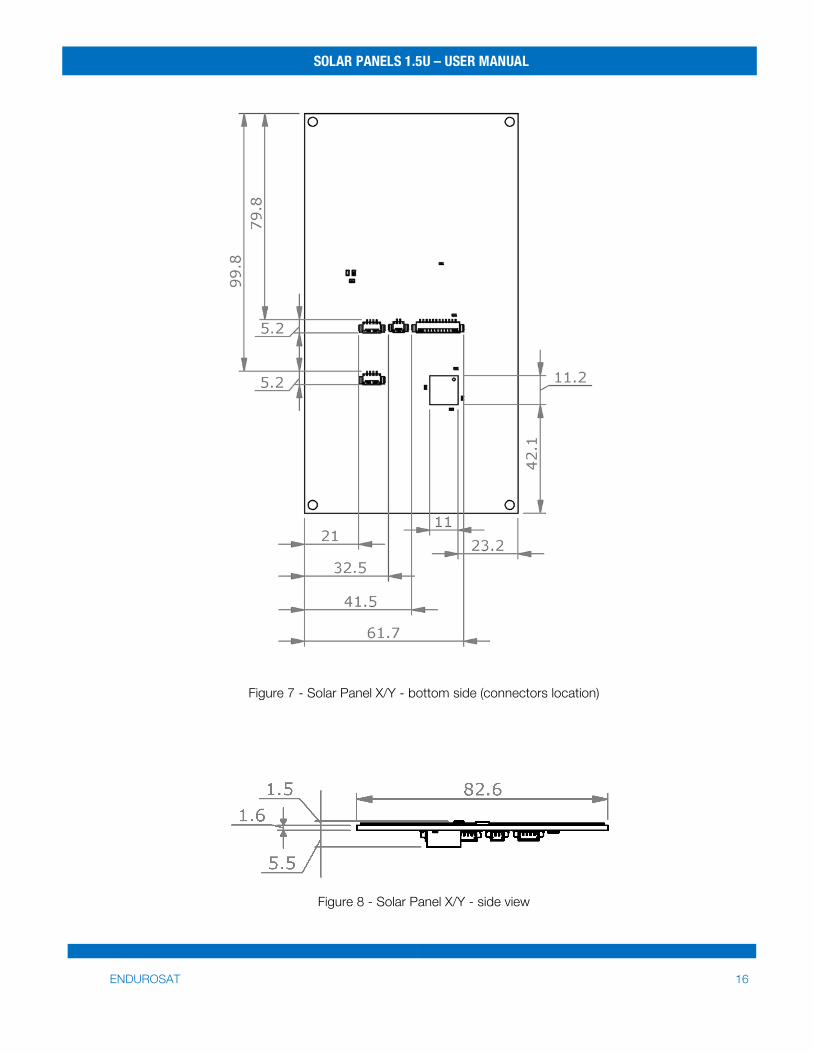
Figure 7 - Solar Panel X/Y - bottom side (connectors location)
Figure 8 - Solar Panel X/Y - side view
SOLAR PANELS 1.5U – USER MANUAL
ENDUROSAT 17
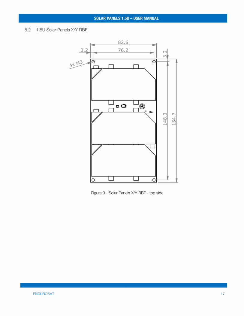
8.2 1.5U Solar Panels X/Y RBF
Figure 9 - Solar Panels X/Y RBF - top side
SOLAR PANELS 1.5U – USER MANUAL
ENDUROSAT 18
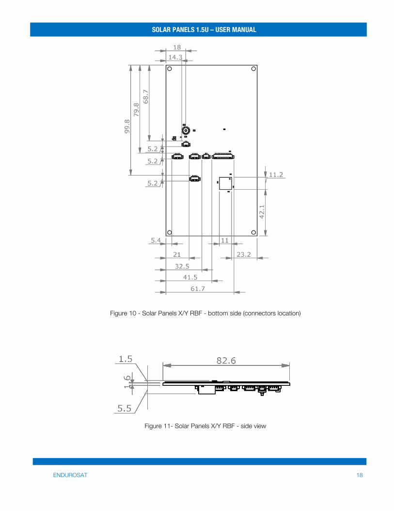
Figure 10 - Solar Panels X/Y RBF - bottom side (connectors location)
Figure 11- Solar Panels X/Y RBF - side view
SOLAR PANELS 1.5U – USER MANUAL
ENDUROSAT 19
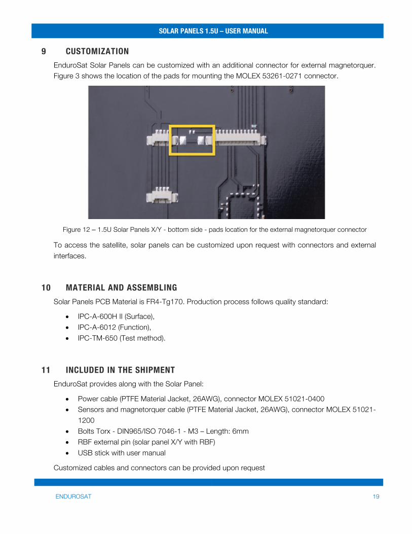
9 CUSTOMIZATION EnduroSat Solar Panels can be customized with an additional connector for external magnetorquer. Figure 3 shows the location of the pads for mounting the MOLEX 53261-0271 connector.
Figure 12 – 1.5U Solar Panels X/Y - bottom side - pads location for the external magnetorquer connector
To access the satellite, solar panels can be customized upon request with connectors and external interfaces.
10 MATERIAL AND ASSEMBLING Solar Panels PCB Material is FR4-Tg170. Production process follows quality standard:
• IPC-A-600H Ⅱ (Surface), • IPC-A-6012 (Function), • IPC-TM-650 (Test method).
11 INCLUDED IN THE SHIPMENT EnduroSat provides along with the Solar Panel:
• Power cable (PTFE Material Jacket, 26AWG), connector MOLEX 51021-0400 • Sensors and magnetorquer cable (PTFE Material Jacket, 26AWG), connector MOLEX 51021-
1200 • Bolts Torx - DIN965/ISO 7046-1 - M3 – Length: 6mm • RBF external pin (solar panel X/Y with RBF) • USB stick with user manual
Customized cables and connectors can be provided upon request
SOLAR PANELS 1.5U – USER MANUAL
ENDUROSAT 20
12 HANDLING AND STORAGE Particular attention shall be paid to the avoidance of damage to the Solar Cells of the solar panels during handling, storage and preservation. The handling of the Solar Panel should be performed in compliance with the following instructions:
• Handle using PVC, latex, cotton (lint free) or nylon gloves. • The environment where the solar panels will be handled shall meet the requirements for a
class environment 100,000, free of contaminants such dust, oil, grease, fumes and smoke from any source.
• Do not touch the solar cells • Solar panels must be handled by touching PCB edges only • Solar Panels shall be stored in such a manner as to preclude stress and prevent damage • To prevent the deterioration of the Solar Cells, Solar panel must be stored in a controlled
environment, i.e. the temperature and humidity levels shall be maintained in the proper ranges:
o Ideal storage temperature range: 15ºC to 27ºC o Ideal storage humidity range: 30% to 60% relative humidity (RH)
SOLAR PANELS 1.5U – USER MANUAL
ENDUROSAT 21
13 WARNINGS
This product uses very fragile components. Observe precautions for Handling.
This product uses semiconductors that can be damaged by electrostatic discharge (ESD). Observe precautions for Handling
Sensitive Electronic device. Do not ship or store near strong electrostatic, electromagnetic, magnetic or radioactive fields.
Related Documents


