PDF generated using the open source mwlib toolkit. See http://code.pediapress.com/ for more information. PDF generated at: Sun, 06 Mar 2011 20:24:54 UTC Solar Energy Home Design

Welcome message from author
This document is posted to help you gain knowledge. Please leave a comment to let me know what you think about it! Share it to your friends and learn new things together.
Transcript

PDF generated using the open source mwlib toolkit. See http://code.pediapress.com/ for more information.PDF generated at: Sun, 06 Mar 2011 20:24:54 UTC
Solar Energy Home Design

ContentsArticlesIntroduction 1
Passive solar building design 1Zero-energy building 12Passive house 23Green building 32Daylight harvesting 39Daylighting 42Solar thermal energy 48
Tools 65
Architectural light shelf 65Roof lantern 66Oculus 67Light tube 69Clerestory 75LiTraCon 78Sunroom 79Greenhouse 81Green roof 86Cool roof 96Solar water heating 104Trombe wall 123Windcatcher 126Barra system 129Brise soleil 131Earth sheltering 133Superinsulation 142Solar air conditioning 145Passive cooling 150Absorption heat pump 152Radiant cooling 154Natural ventilation 156Underfloor air distribution 160

Solar chimney 163Solar lamp 167Solar cooker 168Ground-coupled heat exchanger 176Seasonal thermal store 180Absorption refrigerator 184Annualized geo solar 187
ReferencesArticle Sources and Contributors 188Image Sources, Licenses and Contributors 192
Article LicensesLicense 196

1
Introduction
Passive solar building design
Elements of passive solar design, shown in a directgain application
Active and passive solar systems are used in the Solar Umbrellahouse to achieve nearly 100% energy neutrality.
In passive solar building design, windows, walls, andfloors are made to collect, store, and distribute solarenergy in the form of heat in the winter and reject solarheat in the summer. This is called passive solar designor climatic design because, unlike active solar heatingsystems, it doesn't involve the use of mechanical andelectrical devices.
The key to designing a passive solar building is to besttake advantage of the local climate. Elements to beconsidered include window placement and glazingtype, thermal insulation, thermal mass, and shading.Passive solar design techniques can be applied mosteasily to new buildings, but existing buildings can beadapted or "retrofitted".
As a science
The scientific basis for passive solar building designhas been developed from a combination of climatology,thermodynamics (particularly heat transfer), and humanthermal discomfort (for buildings to be inhabited byhumans and animals). Specific attention is dissected tothe site and location of the dwelling, the prevailinglevel of rain, design and construction, solar orientation,placement of walls, and incorporation of biomass.While these considerations may be directed to anybuilding, achieving an ideal solution requires carefulintegration of these principles. Modern refinementsthrough computer modeling and application of othertechnology can achieve significant energy savingswithout necessarily sacrificing functionality oraesthetics.[1] [2] In fact it is for this reason that thisnewly coined term, known as Architectural Science orArchitectural Technology, has become an upcomingsubject area in most schools of Architecture worldwide.

Passive solar building design 2
The solar path in passive design
Solar altitude over a year; latitude based on New York, New York
The ability to achieve these goalssimultaneously is fundamentally dependenton the seasonal variations in the sun's paththroughout the day.This occurs as a result of the inclination ofthe Earth's axis of rotation in relation to itsorbit. The sun path is unique for any givenlatitude.
In Northern Hemisphere non-tropicallatitudes farther than 23.5 degrees from theequator:• The sun will reach its highest point
toward the South (in the direction of theequator)
• As winter solstice approaches, the angle at which the sun rises and sets progressively moves further toward theSouth and the daylight hours will become shorter
• The opposite is noted in summer where the sun will rise and set further toward the North and the daylight hourswill lengthen[3]
The converse is observed in the Southern Hemisphere, but the sun rises to the east and sets toward the westregardless of which hemisphere you are in.In equatorial regions at less than 23.5 degrees, the position of the sun at solar noon will oscillate from north to southand back again during the year.[4]
In regions closer than 23.5 degrees from either north-or-south pole, during summer the sun will trace a completecircle in the sky without setting whilst it will never appear above the horizon six months later, during the height ofwinter.[5]
The 47-degree difference in the altitude of the sun at solar noon between winter and summer forms the basis ofpassive solar design. This information is combined with local climatic data (degree day) heating and coolingrequirements to determine at what time of the year solar gain will be beneficial for thermal comfort, and when itshould be blocked with shading. By strategic placement of items such as glazing and shading devices, the percent ofsolar gain entering a building can be controlled throughout the year.One passive solar sun path design problem is that although the sun is in the same relative position six weeks before,and six weeks after, the solstice, due to "thermal lag" from the thermal mass of the Earth, the temperature and solargain requirements are quite different before and after the summer or winter solstice. Movable shutters, shades, shadescreens, or window quilts can accommodate day-to-day and hour-to-hour solar gain and insulation requirements.Careful arrangement of rooms completes the passive solar design. A common recommendation for residentialdwellings is to place living areas facing solar noon and sleeping quarters on the opposite side.[6] A heliodon is atraditional movable light device used by architects and designers to help model sun path effects. In modern times, 3Dcomputer graphics can visually simulate this data, and calculate performance predictions.[1]

Passive solar building design 3
Passive solar thermodynamic principles
Solar panels are used in passive andactive solar hot water systems
Personal thermal comfort is a function of personal health factors (medical,psychological, sociological and situational),ambient air temperature, meanradiant temperature, air movement (wind chill, turbulence) and relativehumidity (affecting human evaporative cooling). Heat transfer in buildingsoccurs through convection, conduction, and thermal radiation through roof,walls, floor and windows.[7]
Convective heat transfer
Convective heat transfer can be beneficial or detrimental. Uncontrolled airinfiltration from poor weatherization / weatherstripping / draft-proofing cancontribute up to 40% of heat loss during winter,[8] however strategic placement of operable windows or vents canenhance convection, cross-ventilation, and summer cooling when the outside air is of a comfortable temperature andrelative humidity.[9] Filtered energy recovery ventilation systems may be useful to eliminate undesirable humidity,dust, pollen, and microorganisms in unfiltered ventilation air.
Natural convection causing rising warm air and falling cooler air can result in an uneven stratification of heat. Thismay cause uncomfortable variations in temperature in the upper and lower conditioned space, serve as a method ofventing hot air, or be designed in as a natural-convection air-flow loop for passive solar heat distribution andtemperature equalization. Natural human cooling by perspiration and evaporation may be facilitated through naturalor forced convective air movement by fans, but ceiling fans can disturb the stratified insulating air layers at the top ofa room, and accelerate heat transfer from a hot attic, or through near by windows. In addition, high relative humidityinhibits evaporative cooling by humans.
Radiative heat transferThe main source of heat transfer is radiant energy, and the primary source is the sun. Solar radiation occurspredominantly through the roof and windows (but also through walls). Thermal radiation moves from a warmersurface to a cooler one. Roofs receive the majority of the solar radiation delivered to a house. A cool roof, or greenroof in addition to a radiant barrier can help prevent your attic from becoming hotter than the peak summer outdoorair temperature[10] (see albedo, absorptivity, emissivity, and reflectivity).Windows are a ready and predictable site for thermal radiation.[11] Energy from radiation can move into a window inthe day time, and out of the same window at night. Radiation uses photons to transmit electromagnetic wavesthrough a vacuum, or translucent medium. Solar heat gain can be significant even on cold clear days. Solar heat gainthrough windows can be reduced by insulated glazing, shading, and orientation. Windows are particularly difficult toinsulate compared to roof and walls. Convective heat transfer through and around window coverings also degrade itsinsulation properties.[11] When shading windows, external shading is more effective at reducing heat gain thaninternal window coverings.[11]
Western and eastern sun can provide warmth and lighting, but are vulnerable to overheating in summer if not shaded.In contrast, the low midday sun readily admits light and warmth during the winter, but can be easily shaded withappropriate length overhangs or angled louvres during summer. The amount of radiant heat received is related to thelocation latitude, altitude, cloud cover, and seasonal / hourly angle of incidence (see Sun path and Lambert's cosinelaw).Another passive solar design principle is that thermal energy can be stored in certain building materials and releasedagain when heat gain eases to stabilize diurnal (day/night) temperature variations. The complex interaction ofthermodynamic principles can be counterintuitive for first-time designers. Precise computer modeling can help avoidcostly construction experiments.

Passive solar building design 4
Site specific considerations during design• Latitude and sun path• Seasonal variations in solar gain e.g. cooling or heating degree days, solar insolation, humidity• Diurnal variations in temperature• Micro-climate details related to breezes, humidity, vegetation and land contour• Obstructions / Over-shadowing - to solar gain or local cross-winds
Design elements for residential buildings in temperate climates• Placement of room-types, internal doors & walls, & equipment in the house.• Orienting the building to face the equator (or a few degrees to the East to capture the morning sun)[6]
• Extending the building dimension along the east/west axis• Adequately sizing windows to face the midday sun in the winter, and be shaded in the summer.• Minimising windows on other sides, especially western windows[11]
• Erecting correctly sized, latitude-specific roof overhangs,[12] or shading elements (shrubbery, trees, trellises,fences, shutters, etc.)[13]
• Using the appropriate amount and type of insulation including radiant barriers and bulk insulation to minimiseseasonal excessive heat gain or loss
• Using thermal mass to store excess solar energy during the winter day (which is then re-radiated during thenight)[14]
The precise amount of equator-facing glass and thermal mass should be based on careful consideration of latitude,altitude, climatic conditions, and heating/cooling degree day requirements.Factors that can degrade thermal performance:• Deviation from ideal orientation and north/south/east/west aspect ratio• Excessive glass area ('over-glazing') resulting in overheating (also resulting in glare and fading of soft
furnishings) and heat loss when ambient air temperatures fall• Installing glazing where solar gain during the day and thermal losses during the night cannot be controlled easily
e.g. West-facing, angled glazing, skylights[15]
• Thermal losses through non-insulated or unprotected glazing• Lack of adequate shading during seasonal periods of high solar gain (especially on the West wall)• Incorrect application of thermal mass to modulate daily temperature variations• Open staircases leading to unequal distribution of warm air between upper and lower floors as warm air rises• High building surface area to volume - Too many corners• Inadequate weatherization leading to high air infiltration• Lack of, or incorrectly installed, radiant barriers during the hot season. (See also cool roof and green roof)• Insulation materials that are not matched to the main mode of heat transfer (e.g. undesirable
convective/conductive/radiant heat transfer)

Passive solar building design 5
Efficiency and economics of passive solar heatingTechnically, PSH is highly efficient. Direct-gain systems can utilize (i.e. convert into "useful" heat) 65-70% of theenergy of solar radiation that strikes the aperture or collector. To put this in perspective relative to another energyconversion process, the photosynthetic efficiency theoretical limit is around 11%.Passive solar fraction (PSF) is the percentage of the required heat load met by PSH and hence represents potentialreduction in heating costs. RETScreen International has reported a PSF of 20-50%. It must be noted that within thefield of sustainability, energy conservation even of the order of 15% is considered substantial.Other sources report the following PSFs:• 5-25% for modest systems• 40% for "highly optimized" systems• Up to 75% for "very intense" systemsIn favorable climates such as the southwest United States, highly optimized systems can exceed 75% PSF.[16]
Key passive solar building design conceptsThere are six primary passive solar energy configurations:[17]
• direct solar gain• indirect solar gain• isolated solar gain• heat storage• insulation and glazing• passive cooling
Direct solar gainDirect gain attempts to control the amount of direct solar radiation reaching the living space. This direct solar gain isa critical part of passive solar house designation as it imparts to a direct gain.The cost effectiveness of these configurations are currently being investigated in great detail and are demonstratingpromising results.[18]
Indirect solar gainIndirect gain attempts to control solar radiation reaching an area adjacent but not part of the living space. Heat entersthe building through windows and is captured and stored in thermal mass (e.g. water tank, masonry wall) and slowlytransmitted indirectly to the building through conduction and convection. Efficiency can suffer from slow response(thermal lag) and heat losses at night. Other issues include the cost of insulated glazing and developing effectivesystems to redistribute heat throughout the living area.
Isolated solar gainIsolated gain involves utilizing solar energy to passively move heat from or to the living space using a fluid, such aswater or air by natural convection or forced convection. Heat gain can occur through a sunspace, solarium or solarcloset. These areas may also be employed usefully as a greenhouse or drying cabinet. An equator-side sun room mayhave its exterior windows higher than the windows between the sun room and the interior living space, to allow thelow winter sun to penetrate to the cold side of adjacent rooms. Glass placement and overhangs prevent solar gainduring the summer. Earth cooling tubes or other passive cooling techniques can keep a solarium cool in the summer.Measures should be taken to reduce heat loss at night e.g. window coverings or movable window insulationExamples:

Passive solar building design 6
• Thermosiphon• Barra system• Double envelope house• Thermal buffer zone[19]
• Solar space heating system• Solar chimney
Heat StorageThe sun doesn't shine all the time. Heat storage, or thermal mass keeps the building warm when the sun can't heat it.In diurnal solar houses, the storage is designed for one or a few days. The usual method is a custom-constructedthermal mass. These include a Trombe wall, a ventilated concrete floor, a cistern, water wall or roof pond.In subarctic areas, or areas that have long terms without solar gain (e.g. weeks of freezing fog), purpose-built thermalmass is very expensive. Don Stephens pioneered an experimental technique to use the ground as thermal mass largeenough for annualized heat storage. His designs run an isolated thermosiphon 3m under a house, and insulate theground with a 6m waterproof skirt.[20]
InsulationThermal insulation or superinsulation (type, placement and amount) reduces unwanted leakage of heat.[7] Somepassive buildings are actually constructed of insulation.
Special glazing systems and window coveringsThe effectiveness of direct solar gain systems is significantly enhanced by insulative (e.g. double glazing), spectrallyselective glazing (low-e), or movable window insulation (window quilts, bifold interior insulation shutters, shades,etc.).[21]
Generally, Equator-facing windows should not employ glazing coatings that inhibit solar gain.There is extensive use of super-insulated windows in the German Passive House standard. Selection of differentspectrally selective window coating depends on the ratio of heating versus cooling degree days for the designlocation.
Glazing selection
Equator-facing glass
The requirement for vertical equator-facing glass is different from the other three sides of a building. Reflectivewindow coatings and multiple panes of glass can reduce useful solar gain. However, direct-gain systems are moredependent on double or triple glazing to reduce heat loss. Indirect-gain and isolated-gain configurations may still beable to function effectively with only single-pane glazing. Nevertheless, the optimal cost-effective solution is bothlocation and system dependent.

Passive solar building design 7
Roof-angle glass / Skylights
Skylights admit sunlight either horizontally (a flat roof) or pitched at the same angle as the roof slope. In most cases,horizontal skylights are used with reflectors to increase the intensity of solar radiation depending on the angle ofincidence. Large skylights should be provided with shading devices to prevent heat loss at night and heat gain duringthe summer months.Skylights on roofs that face away from the equator provide fairly constant but cool illumination. Those oneast-facing roofs provide maximum light and solar heat gain in the morning. West-facing skylights provide afternoonsunlight and heat gain. Equatorial-facing skylights provide the greatest potential for desirable winter passive solarheat gain than any other location, but often allow unwanted heat gain in the summer. You can prevent unwantedsolar heat gain by installing the skylight in the shade of deciduous (leaf-shedding) trees or adding a movable windowcovering on the inside or outside of the skylight. Some modern designs have special glazing that can help controlsolar heat gain while still allowing high levels of visible light transmittance. Skylights are often the only method tobring passive solar into the core of a commercial or industrial application.
Angle of incident radiation
The amount of solar gain transmitted through glass is also affected by the angle of the incident solar radiation.Sunlight striking glass within 20 degrees of perpendicular is mostly transmitted through the glass, whereas sunlightat more than 35 degrees from perpendicular is mostly reflected[22]
All of these factors can be modeled more precisely with a photographic light meter and a heliodon or optical bench,which can quantify the ratio of reflectivity to transmissivity, based on angle of incidence.Alternatively, passive solar computer software can determine the impact of sun path, and cooling-and-heating degreedays on energy performance. Regional climatic conditions are often available from local weather services.
Operable shading and insulation devicesA design with too much equator-facing glass can result in excessive winter, spring, or fall day heating,uncomfortably bright living spaces at certain times of the year, and excessive heat transfer on winter nights andsummer days.Although the sun is at the same altitude 6-weeks before and after the solstice, the heating and cooling requirementsbefore and after the solstice are significantly different. Heat storage on the Earth's surface causes "thermal lag."Variable cloud cover influences solar gain potential. This means that latitude-specific fixed window overhangs,while important, are not a complete seasonal solar gain control solution.Control mechanisms (such as manual-or-motorized interior insulated drapes, shutters, exterior roll-down shadescreens, or retractable awnings) can compensate for differences caused by thermal lag or cloud cover, and helpcontrol daily / hourly solar gain requirement variations.Home automation systems that monitor temperature, sunlight, time of day, and room occupancy can preciselycontrol motorized window-shading-and-insulation devices.

Passive solar building design 8
Exterior colors reflecting - absorbingMaterials and colors can be chosen to reflect or absorb solar thermal energy. Using information on a Color forelectromagnetic radiation to determine its thermal radiation properties of reflection or absorption can assist thechoices.See Lawrence Berkeley National Laboratory and Oak Ridge National Laboratory: "Cool Colors" [23]
Landscaping and gardensEnergy-efficient landscaping materials for careful passive solar choices include hardscape building material and"softscape" plants. The use of landscape design principles for selection of trees, hedges, and trellis-pergola featureswith vines; all can be used to create summer shading. For winter solar gain it is desirable to use deciduous plants thatdrop their leaves in the autumn gives year round passive solar benefits. Non-deciduous evergreen shrubs and treescan be windbreaks, at variable heights and distances, to create protection and shelter from winter wind chill.Xeriscaping with 'mature size appropriate' native species of-and drought tolerant plants, drip irrigation, mulching,and organic gardening practices reduce or eliminate the need for energy-and-water-intensive irrigation, gas poweredgarden equipment, and reduces the landfill waste footprint. Solar powered landscape lighting and fountain pumps,and covered swimming pools and plunge pools with solar water heaters can reduce the impact of such amenities.• Sustainable gardening• Sustainable landscaping• Sustainable landscape architecture
Other passive solar principles
Passive solar lightingPassive solar lighting techniques enhance taking advantage of natural illumination for interiors, and so reducereliance on artificial lighting systems.This can be achieved by careful building design, orientation, and placement of window sections to collect light.Other creative solutions involve the use of reflecting surfaces to admit daylight into the interior of a building.Window sections should be adequately sized, and to avoid over-illumination can be shielded with a Brise soleil,awnings, well placed trees, glass coatings, and other passive and active devices.[17]
Another major issue for many window systems is that they can be potentially vulnerable sites of excessive thermalgain or heat loss. Whilst high mounted clerestory window and traditional skylights can introduce daylight in poorlyoriented sections of a building, unwanted heat transfer may be hard to control.[24] [25] Thus, energy that is saved byreducing artificial lighting is often more than offset by the energy required for operating HVAC systems to maintainthermal comfort.Various methods can be employed to address this including but not limited to window coverings, insulated glazingand novel materials such as aerogel semi-transparent insulation, optical fiber embedded in walls or roof, or hybridsolar lighting at Oak Ridge National Laboratory [26].
Interior reflecting
Reflecting elements, from active and passive daylighting collectors, such as light shelves, lighter wall and floor colors, mirrored wall sections, interior walls with upper glass panels, and clear or translucent glassed hinged doors and sliding glass doors take the captured light and passively reflect it further inside. The light can be from passive windows or skylights and solar light tubes or from active daylighting sources. In traditional Japanese architecture the Shōji sliding panel doors, with translucent Washi screens, are an original precedent. International style, Modernist and Mid-century modern architecture were earlier innovators of this passive penetration and reflection in industrial,

Passive solar building design 9
commercial, and residential applications.
Passive solar water heatingThere are many ways to use solar thermal energy to heat water for domestic use. Different active-and-passive solarhot water technologies have different location-specific economic cost benefit analysis implications.Fundamental passive solar hot water heating involves no pumps or anything electrical. It is very cost effective inclimates that do not have lengthy sub-freezing, or very-cloudy, weather conditions. Other active solar water heatingtechnologies, etc. may be more appropriate for some locations.It is possible to have active solar hot water which is also capable of being "off grid" and qualifies as sustainable. Thisis done by the use of a photovoltaic cell which uses energy from the sun to power the pumps.
Comparison to the Passive House standard in EuropeThere is growing momentum in Europe for the approach espoused by the Passive House Institute in Germany.Rather than relying solely on traditional passive solar design techniques, this approach seeks to make use of allpassive sources of heat, minimises energy usage, and emphasises the need for high levels of insulation reinforced bymeticulous attention to detail in order to address thermal bridging and cold air infiltration. Most of the buildings builtto the Passive House standard also incorporate an active heat recovery ventilation unit with or without a small(typically 1 kW) incorporated heating component.The energy design of Passive House buildings is developed using a spreadsheet-based modeling tool called thePassive House Planning Package (PHPP) which is updated periodically. The current version is PHPP2007, where2007 is the year of issue. A building may be certified as a 'Passive House' when it can be shown that it meets certaincriteria, the most important being that the annual specific heat demand for the house should not exceed 15kWh/m2a.
Design toolsTraditionally a heliodon was used to simulate the altitude and azimuth of the sun shining on a model building at anytime of any day of the year.[27] In modern times, computer programs can model this phenomenon and integrate localclimate data (including site impacts such as overshadowing and physical obstructions) to predict the solar gainpotential for a particular building design over the course of a year. This provides the designer the ability to evaluatedesign elements and orientation prior to building works commencing. Energy performance optimization normallyrequires an iterative-refinement design-and-evaluate process.
Levels of application
PragmaticMany detached suburban houses can achieve reductions in heating expense without obvious changes to theirappearance, comfort or usability.[28] This is done using good siting and window positioning, small amounts ofthermal mass, with good-but-conventional insulation, weatherization, and an occasional supplementary heat source,such as a central radiator connected to a (solar) water heater. Sunrays may fall on a wall during the daytime and raisethe temperature of its thermal mass. This will then radiate heat into the building in the evening. This can be aproblem in the summer, especially on western walls in areas with high degree day cooling requirements. Externalshading, or a radiant barrier plus air gap, may be used to reduce undesirable summer solar gain.

Passive solar building design 10
AnnualisedAn extension of the "passive solar" approach to seasonal solar capture and storage of heat and cooling. These designsattempt to capture warm-season solar heat, and convey it to a seasonal thermal store for use months later during thecold season ("annualised passive solar.") Increased storage is achieved by employing large amounts of thermal massor earth coupling. Anecdotal reports suggest they can be effective but no formal study has been conducted todemonstrate their superiority. The approach also can move cooling into the warm season.Examples:• Passive Annual Heat Storage (PAHS) - by John Hait• Annualized Geothermal Solar (AGS) heating - by Don Stephen• Earthed-roof
Minimum machineryA "purely passive" solar-heated house would have no mechanical furnace unit, relying instead on energy capturedfrom sunshine, only supplemented by "incidental" heat energy given off by lights, computers, and other task-specificappliances (such as those for cooking, entertainment, etc.), showering, people and pets. The use of naturalconvection air currents (rather than mechanical devices such as fans) to circulate air is related, though not strictlysolar design.Passive solar building design sometimes uses limited electrical and mechanical controls to operate dampers,insulating shutters, shades, awnings, or reflectors. Some systems enlist small fans or solar-heated chimneys toimprove convective air-flow. A reasonable way to analyse these systems is by measuring their coefficient ofperformance. A heat pump might use 1 J for every 4 J it delivers giving a COP of 4. A system that only uses a 30 Wfan to more-evenly distribute 10 kW of solar heat through an entire house would have a COP of 300.
Zero Energy BuildingPassive solar building design is often a foundational element of a cost-effective zero energy building.[29] [30] [31]
Although a ZEB uses multiple passive solar building design concepts, a ZEB is usually not purely passive, havingactive mechanical renewable energy generation systems such as: wind turbine, photovoltaics, micro hydro,geothermal, and other emerging alternative energy sources.
References[1] "Rating tools" (http:/ / web. archive. org/ web/ 20070930015551/ http:/ / www. greenhouse. gov. au/ yourhome/ technical/ fs110. htm).
Archived from the original (http:/ / www. greenhouse. gov. au/ yourhome/ technical/ fs110. htm) on September 30, 2007. . Retrieved2008-01-14.
[2] Your Home Design Guide - Home Page (http:/ / www. greenhouse. gov. au/ yourhome/ technical/ fs71. htm)[3] http:/ / www. srrb. noaa. gov/ highlights/ sunrise/ fig5_40n. gif[4] http:/ / www. srrb. noaa. gov/ highlights/ sunrise/ fig5_0n. gif[5] http:/ / www. srrb. noaa. gov/ highlights/ sunrise/ fig5_90n. gif[6] Your Home Design Guide - Home Page (http:/ / www. greenhouse. gov. au/ yourhome/ technical/ fs13. htm)[7] Your Home Design Guide - Home Page (http:/ / www. greenhouse. gov. au/ yourhome/ technical/ fs16a. htm)[8] "BERC - Airtightness" (http:/ / www. ornl. gov/ sci/ roofs+ walls/ whole_wall/ airtight. html). Ornl.gov. 2004-05-26. . Retrieved 2010-03-16.[9] Your Home Design Guide - Home Page (http:/ / www. greenhouse. gov. au/ yourhome/ technical/ fs15. htm)[10] "EERE Radiant Barriers" (http:/ / www. eere. energy. gov/ consumer/ your_home/ insulation_airsealing/ index. cfm/ mytopic=11680).
Eere.energy.gov. 2009-05-28. . Retrieved 2010-03-16.[11] "Glazing - Overview" (http:/ / web. archive. org/ web/ 20071215075543/ http:/ / www. greenhouse. gov. au/ yourhome/ technical/ fs18a.
htm). Archived from the original (http:/ / www. greenhouse. gov. au/ yourhome/ technical/ fs18a. htm) on December 15, 2007. . Retrieved2008-01-14.
[12] Springer, John L. (December 1954). "The 'Big Piece' Way to Build" (http:/ / www. popsci. com/ archive-viewer?id=1yADAAAAMBAJ&pg=157& query=1955). Popular Science 165 (6): 157. .
[13] Your Home Design Guide - Technical Manual - Shading (http:/ / www. yourhome. gov. au/ technical/ fs44. html)

Passive solar building design 11
[14] Your Home Design Guide - Technical Manual - Thermal Mass (http:/ / www. yourhome. gov. au/ technical/ fs49. html)[15] "Introductory Passive Solar Energy Technology Overview" (http:/ / www. passivesolarenergy. info/ #S1). U.S. DOE - ORNL Passive Solar
Workshop. . Retrieved 2007-12-23.[16] "Passive Solar Design" (http:/ / www. nmsea. org/ Passive_Solar/ Passive_Solar_Design. htm). New Mexico Solar Association. .[17] Chiras, D. The Solar House: Passive Heating and Cooling. Chelsea Green Publishing Company; 2002.[18] "Zero Energy Buildings" (http:/ / www. fsec. ucf. edu/ en/ research/ buildings/ zero_energy/ index. htm). Fsec.ucf.edu. . Retrieved
2010-03-16.[19] "Two Small Delta Ts Are Better Than One Large Delta T" (http:/ / www. zeroenergydesign. com/ Passive Solar Cooling. html#c22). Zero
Energy Design. . Retrieved 2007-12-23.[20] Annualized Geo-Solar Heating, Don Stephens (http:/ / greenershelter. org/ TokyoPaper. pdf)- Accessed 2009-02-05[21] William A. Shurcliff. Thermal Shutters & Shades - Over 100 Schemes for Reducing Heat Loss through Windows 1980.
ISBN 0-931790-14-X.[22] "Solar Heat Gain Through Glass" (http:/ / irc. nrc-cnrc. gc. ca/ pubs/ cbd/ cbd039_e. html). Irc.nrc-cnrc.gc.ca. 2010-03-08. . Retrieved
2010-03-16.[23] http:/ / www. energy. ca. gov/ 2006publications/ CEC-500-2006-067/ CEC-500-2006-067. PDF[24] "[ARCHIVED CONTENT] Insulating and heating your home efficiently : Directgov - Environment and greener living" (http:/ / www.
direct. gov. uk/ en/ Environmentandgreenerliving/ Greenerhome/ DG_064374). Direct.gov.uk. . Retrieved 2010-03-16.[25] "Reduce Your Heating Bills This Winter - Overlooked Sources of Heat Loss in the Home" (http:/ / www. allwoodwork. com/ article/
homeimprovement/ reduce_your_heating_bills. html). Allwoodwork.com. 2003-02-14. . Retrieved 2010-03-16.[26] http:/ / www. ornl. gov/ sci/ solar/[27] (http:/ / www. heliodon. com. mx/ productos/ heliodon/ gal/ helio_u_c_colon. JPG)[28] "Industrial Technologies Program: Industrial Distributed Energy" (http:/ / www. eere. energy. gov/ de/ passive_solar_design. html).
Eere.energy.gov. . Retrieved 2010-03-16.[29] "Cold-Climate Case Study for Affordable Zero Energy Homes: Preprint" (http:/ / www. nrel. gov/ docs/ fy06osti/ 39678. pdf) (PDF). .
Retrieved 2010-03-16.[30] "Zero Energy Homes: A Brief Primer" (http:/ / www. toolbase. org/ PDF/ CaseStudies/ ZEHPrimer. pdf) (PDF). . Retrieved 2010-03-16.[31] Moving Toward Zero Energy Homes (Fact Sheet) (http:/ / www. eere. energy. gov/ buildings/ info/ documents/ pdfs/ 35317. pdf)
External links• www.solarbuildings.ca (http:/ / www. solarbuildings. ca/ ) - Canadian Solar Buildings Research Network• www.greenbuilder.com (http:/ / www. greenbuilder. com/ sourcebook/ PassiveSol. html) - Passive Solar Design• Direct space heating and daylighting (http:/ / www. practicalsolar. com/ photos/ photos. html) with heliostats
(photos)• www.eere.energy.gov (http:/ / www. eere. energy. gov/ de/ passive_solar_design. html) - US Department of
Energy (DOE) Guidelines• www.greenhouse.gov.au (http:/ / www. greenhouse. gov. au) - Australian Dept of Climate Change• www.ornl.gov (http:/ / www. ornl. gov/ sci/ btc/ apps/ ) - Oak Ridge National Laboratory (ORNL) Building
Technology• www.FSEC.UCF.edu (http:/ / www. FSEC. UCF. edu) - Florida Solar Energy Center• www.ZeroEnergyDesign.com (http:/ / www. ZeroEnergyDesign. com) - 28 Years of Passive Solar Building
Design• Passive Solar Design Guidelines (http:/ / nmsea. org/ Curriculum/ Courses/ Passive_Solar_Design/ Guidelines/
Guidelines. htm)• http:/ / www. solaroof. org/ wiki• Calculation of insolation (houses, garden, roof, apartment...) (http:/ / www. sun-time. org/ english)• www.PassiveSolarEnergy.info (http:/ / www. PassiveSolarEnergy. info) - Passive Solar Energy Technology
Overview• www.gaisma.com (http:/ / www. gaisma. com)- Sun path calculator for selected cites• http:/ / sunposition. info/ sunposition/ spc/ locations. php (http:/ / sunposition. info/ sunposition/ spc/ locations.
php) - Sun path by location and date• www.yourhome.gov.au/technical/index.html (http:/ / www. yourhome. gov. au/ technical/ index. html) -
Technical Manual developed by the Commonwealth of Australia to promote good design and sustainable homes.

Passive solar building design 12
• amergin.tippinst.ie/downloadsEnergyArchhtml.html (http:/ / amergin. tippinst. ie/ downloadsEnergyArchhtml.html)- Energy in Architecture, The European Passive Solar Handbook, Goulding J.R, Owen Lewis J, SteemersTheo C, Sponsored by the European Commission, published by Batsford 1986, reprinted 1993
• www.viking-house.ie (http:/ / www. viking-house. ie/ solar-house) High standard in Passive solar design Co.Cork Ireland
• www.solaraspects.com (http:/ / www. solaraspects. com) - website that provides advice on maximizing the solarpassive design potential for new homes
Zero-energy building
BedZED zero energy housing in the UK
A zeronet energy building (ZNE) is a popular term to describe abuilding's use with zero net energy consumption and zero carbonemissions annually. ZeroNet Energy buildings can be usedautonomously from the energy grid supply – energy can beharvested on-site usually in combination with energy producingtechnologies like Solar and Wind while reducing the overall use ofenergy with extremely efficient HVAC and Lighting technologies.The ZeroNet design principle is becoming more practical inadopting due to the increasing costs of traditional fossil fuels andtheir negative impact on the planet's climate and ecologicalbalance.
The ZNE consumption principle is gaining considerable interest as renewable energy harvesting as a means to cutgreenhouse gas emissions. Traditional building use consumes 40% of the total fossil energy in the US and EuropeanUnion.[1] [2] In developing countries many people have to live in zero-energy buildings out of necessity. Manypeople live in huts, yurts, tents and caves exposed to temperature extremes and without access to electricity. Theseconditions and the limited size of living quarters would be considered uncomfortable in the developed countries.
Modern EvolutionThe development of modern ZeroNet Energy (ZNE) buildings became possible not only through the progress madein new construction technologies and techniques, but it has also been significantly improved by academic researchon traditional and experimental buildings, which collected precise energy performance data. Today's advancedcomputer models can show the efficacy of engineering design decisions.Energy use can be measured in different ways (relating to cost, energy, or carbon emissions) and, irrespective of thedefinition used, different views are taken on the relative importance of energy harvest and energy conservation toachieve a net energy balance. Although zero energy buildings remain uncommon in developed countries, they aregaining importance and popularity. The ZeroNet Energy approach has potential to reduce carbon emissions, andreduce dependence on fossil fuels.A building approaching ZeroNet Energy use may be called a near-zero energy building or ultra-low energy house.Buildings that produce a surplus of energy during a portion of the year may be known as energy-plus buildings.If the building is located in an area that requires heating or cooling throughout parts of the year, it is easier to achieveZeroNet Energy consumption when the available living space is kept small.

Zero-energy building 13
DefinitionsDespite sharing the name zeronet energy, there are several definitions of what ZNE means in practice, with aparticular difference in usage between North America and Europe.[3]
ZeroNet site energy useIn this type of ZNE, the amount of energy provided by on-site renewable energy sources is equal to theamount of energy used by the building. In the United States, “zeronet energy building” generally refers to thistype of building.
ZeroNet source energy useThis ZNE generates the same amount of energy as is used, including the energy used to transport the energy tothe building. This type accounts for losses during electricity transmission. These ZNEs must generate moreelectricity than ZeroNet site energy buildings.
Net zero energy emissionsOutside the United States and Canada, a ZEB is generally defined as one with zero net energy emissions, alsoknown as a zero carbon building or zero emissions building. Under this definition the carbon emissionsgenerated from on-site or off-site fossil fuel use are balanced by the amount of on-site renewable energyproduction. Other definitions include not only the carbon emissions generated by the building in use, but alsothose generated in the construction of the building and the embodied energy of the structure. Others debatewhether the carbon emissions of commuting to and from the building should also be included in thecalculation.
Net zero costIn this type of building, the cost of purchasing energy is balanced by income from sales of electricity to thegrid of electricity generated on-site. Such a status depends on how a utility credits net electricity generationand the utility rate structure the building uses.
Net off-site zero energy useA building may be considered a ZEB if 100% of the energy it purchases comes from renewable energysources, even if the energy is generated off the site.
Off-the-gridOff-the-grid buildings are stand-alone ZEBs that are not connected to an off-site energy utility facility. Theyrequire distributed renewable energy generation and energy storage capability (for when the sun is not shining,wind is not blowing, etc.). An energy autarkic house is a building concept where the balance of the ownenergy consumption and production can be made on an hourly or even smaller basis. Energy autarkic housescan be taken off-the-grid.
Design and ConstructionThe most cost-effective steps toward a reduction in a building's energy consumption usually occurs during the design process.[4] To achieve efficient energy use, zero energy design departs significantly from conventional construction practice. Successful zero energy building designers typically combine time tested passive solar, or natural conditioning, principles that work with the on site assets. Sunlight and solar heat, prevailing breezes, and the cool of the earth below a building, can provide daylighting and stable indoor temperatures with minimum mechanical means. ZEBs are normally optimized to use passive solar heat gain and shading, combined with thermal mass to stabilize diurnal temperature variations throughout the day, and in most climates are superinsulated.[5] All the technologies needed to create zero energy buildings are available off-the-shelf today. Sophisticated 3D computer simulation tools are available to model how a building will perform with a range of design variables such as building orientation (relative to the daily and seasonal position of the sun), window and door type and placement, overhang

Zero-energy building 14
depth, insulation type and values of the building elements, air tightness (weatherization), the efficiency of heating,cooling, lighting and other equipment, as well as local climate. These simulations help the designers predict how thebuilding will perform before it is built, and enable them to model the economic and financial implications onbuilding cost benefit analysis, or even more appropriate - life cycle assessment.Zero-Energy Buildings are built with significant energy-saving features. The heating and cooling loads are loweredby using high-efficiency equipment, added insulation, high-efficiency windows, natural ventilation, and othertechniques. These features vary depending on climate zones in which the construction occurs. Water heating loadscan be lowered by using water conservation fixtures, heat recovery units on waste water, and by using solar waterheating, and high-efficiency water heating equipment. In addition, daylighting with skylites or solartubes can provide100% of daytime illumination within the home. Nighttime illumination is typically done with fluorescent and LEDlighting that use 1/3 or less power then incandescent lights, without adding unwanted heat. And miscellaneouselectric loads can be lessened by choosing efficient appliances and minimizing phantom loads or standby power.Other techniques to reach net zero (dependent on climate) are Earth sheltered building principles, superinsulationwalls using straw-bale construction, Vitruvianbuilt [6] pre-fabricated building panels and roof elements plus exteriorlandscaping for seasonal shading.Zero-energy buildings are often designed to make dual use of energy including white goods; for example, usingrefrigerator exhaust to heat domestic water, ventilation air and shower drain heat exchangers, office machines andcomputer servers, and body heat to heat the building. These buildings make use of heat energy that conventionalbuildings may exhaust outside. They may use heat recovery ventilation, hot water heat recycling, combined heat andpower, and absorption chiller units.
Energy harvestZEBs harvest available energy to meet their electricity and heating or cooling needs. In the case of individual houses,various microgeneration technologies may be used to provide heat and electricity to the building, using solar cells orwind turbines for electricity, and biofuels or solar collectors linked to seasonal thermal stores for space heating. Tocope with fluctuations in demand, zero energy buildings are frequently connected to the electricity grid, exportelectricity to the grid when there is a surplus, and drawing electricity when not enough electricity is beingproduced.[7] Other buildings may be fully autonomous.Energy harvesting is most often more effective (in cost and resource utilization) when done on a local but combinedscale, for example, a group of houses, co-housing, local district, village, etc. rather than an individual basis. Anenergy benefit of such localized energy harvesting is the virtual elimination of electrical transmission and electricitydistribution losses. These losses amount to about 7.2%-7.4% of the energy transferred.[8] Energy harvesting incommercial and industrial applications should benefit from the topography of each location. The production of goodsunder net zero fossil energy consumption requires locations of geothermal, microhydro, solar, and wind resources tosustain the concept.[9]
Zero-energy neighborhoods, such as the BedZED development in the United Kingdom, and those that are spreadingrapidly in California and China, may use distributed generation schemes. This may in some cases include districtheating, community chilled water, shared wind turbines, etc. There are current plans to use ZEB technologies tobuild entire off-the-grid or net zero energy use cities.

Zero-energy building 15
The "energy harvest" versus "energy conservation" debateOne of the key areas of debate in zero energy building design is over the balance between energy conservation andthe distributed point-of-use harvesting of renewable energy (solar energy and wind energy). Most zero energy homesuse a combination of the two strategies.As a result of significant government subsidies for photovoltaic solar electric systems, wind turbines, etc., there arethose who suggest that a ZEB is a conventional house with distributed renewable energy harvesting technologies.Entire additions of such homes have appeared in locations where photovoltaic (PV) subsidies are significant,[10] butmany so called "Zero Energy Homes" still have utility bills. This type of energy harvesting without added energyconservation may not be cost effective with the current price of electricity generated with photovoltaic equipment(depending on the local price of power company electricity),[11] and may also requires greater embodied energy andgreater resources so be thus the less ecological approach.Since the 1980s passive solar building design and passive house have demonstrated heating energy consumptionreductions of 70% to 90% in many locations, without active energy harvesting. For new builds, and with expertdesign, this can be accomplished with little additional construction cost for materials over a conventional building.Very few industry experts have the skills or experience to fully capture benefits of the passive design. Such passivesolar designs are much more cost effective than adding expensive photovoltaic panels on the roof of a conventionalinefficient building.[11] A few kilowatt-hours of photovoltaic panels (costing 2 to 3 dollars per annual kW-hrproduction, U.S. dollar equivalent) may only reduce external energy requirements by 15% to 30%. A 100000 BTU(110 MJ) high seasonal energy efficiency ratio 14 conventional air conditioner requires over 7 kW of photovoltaicelectricity while it is operating, and that does not include enough for off-the-grid night-time operation. Passivecooling, and superior system engineering techniques, can reduce the air conditioning requirement by 70% to 90%.Photovoltaic generated electricity becomes more cost-effective when the overall demand for electricity is lower.
Occupant behaviorThe energy used in a building can vary greatly depending on the behavior of its occupants. The acceptance of what isconsidered comfortable varies widely. Studies of identical homes in the United States have shown dramaticdifferences in energy use, with some homes using more than twice the energy of others.[12] Occupant behavior canvary from differences in setting and programming thermostats, varying levels of illumination and hot water, and theamount of miscellaneous electric devices used.[4]
Development effortsWide acceptance of zero energy building technology may require more government incentives or building coderegulations, the development of recognized standards, or significant increases in the cost of conventional energy.The Google photovoltaic campus, and the Microsoft 480-kilowatt photovoltaic campus relied on U.S. Federal, andespecially California, subsidies and financial incentives. California is now providing $3.2 billion USD insubsidies[13] for residential-and-commercial near-zero-energy buildings, due to California's serious electricityshortage, frequent power outages, and air pollution problems. The details of other American states' renewable energysubsidies (up to $5.00 USD per watt) can be found in the Database of State Incentives for Renewables andEfficiency.[14] The Florida Solar Energy Center has a slide presentation on recent progress in this area.[15]
The World Business Council for Sustainable Development[16] has launched a major initiative to support thedevelopment of ZEB. Led by the CEO of United Technologies and the Chairman of Lafarge, the organization hasboth the support of large global companies and the expertise to mobilize the corporate world and governmentalsupport to make ZEB a reality. Their first report, a survey of key players in real estate and construction, indicatesthat the costs of building green are overestimated by 300 percent. Survey respondents estimated that greenhouse gasemissions by buildings are 19 percent of the worldwide total, in contrast to the actual value of roughly 40 percent.[17]

Zero-energy building 16
Influential zero- and low-energy buildingsThose who commissioned construction of Passive Houses and Zero Energy Homes (over the last three decades) wereessential to iterative, incremental, cutting-edge, technology innovations. Much has been learned from manysignificant successes, and a few expensive failures.The zero energy building concept has been a progressive evolution from other low-energy building designs. Amongthese, the Canadian R-2000 and the German passive house standards have been internationally influential.Collaborative government demonstration projects, such as the superinsulated Saskatchewan House, and theInternational Energy Agency's Task 13, have also played their part.
Advantages and disadvantages
Advantages• isolation for building owners from future energy price increases• increased comfort due to more-uniform interior temperatures (this can be demonstrated with comparative
isotherm maps)• reduced requirement for energy austerity• reduced total cost of ownership due to improved energy efficiency• reduced total net monthly cost of living• improved reliability - photovoltaic systems have 25-year warranties - seldom fail during weather problems - the
1982 photovoltaic systems on the Walt Disney World EPCOT Energy Pavilion are still working fine today, aftergoing through 3 recent hurricanes
• extra cost is minimized for new construction compared to an afterthought retrofit• higher resale value as potential owners demand more ZEBs than available supply• the value of a ZEB building relative to similar conventional building should increase every time energy costs
increase• future legislative restrictions, and carbon emission taxes/penalties may force expensive retrofits to inefficient
buildings
Disadvantages• initial costs can be higher - effort required to understand, apply, and qualify for ZEB subsidies• very few designers or builders have the necessary skills or experience to build ZEBs[18]
• possible declines in future utility company renewable energy costs may lessen the value of capital invested inenergy efficiency
• new photovoltaic solar cells equipment technology price has been falling at roughly 17% per year - It will lessenthe value of capital invested in a solar electric generating system - Current subsidies will be phased out asphotovoltaic mass production lowers future price
• challenge to recover higher initial costs on resale of building - appraisers are uninformed - their models do notconsider energy
• climate-specific design may limit future ability to respond to rising-or-falling ambient temperatures (globalwarming)
• while the individual house may use an average of net zero energy over a year, it may demand energy at the timewhen peak demand for the grid occurs. In such a case, the capacity of the grid must still provide electricity to allloads. Therefore, a ZEB may not reduce the required power plant capacity.
• without an optimised thermal envelope the embodied energy, heating and cooling energy and resource usage ishigher than needed. ZEB by definition do not mandate a minimum heating and cooling performance level thusallowing oversized renewable energy systems to fill the energy gap.

Zero-energy building 17
• solar energy capture using the house envelope only works in locations unobstructed from the South. The solarenergy capture cannot be optimized in South facing shade or wooded surroundings.
Zero energy building versus green buildingThe goal of green building and sustainable architecture is to use resources more efficiently and reduce a building'snegative impact on the environment.[19] Zero energy buildings achieve one key green-building goal of completely orvery significantly reducing energy use and greenhouse gas emissions for the life of the building. Zero energybuildings may or may not be considered "green" in all areas, such as reducing waste, using recycled buildingmaterials, etc. However, zero energy, or net-zero buildings do tend to have a much lower ecological impact over thelife of the building compared with other 'green' buildings that require imported energy and/or fossil fuel to behabitable and meet the needs of occupants.Because of the design challenges and sensitivity to a site that are required to efficiently meet the energy needs of abuilding and occupants with renewable energy (solar, wind, geothermal, etc.), designers must apply holistic designprinciples, and take advantage of the free naturally occurring assets available, such as passive solar orientation,natural ventilation, daylighting, thermal mass, and night time cooling.
Certification
Many Green building certification programs do not require a building to have net zero energy use, only to reduceenergy use a few percentage points below the minimum required by law. The Leadership in Energy andEnvironmental Design (LEED) certification developed by the U.S. Green Building Council, and Green Globes,involve check lists that are measurement tools, not design tools. Inexperienced designers or architects maycherry-pick points to meet a target certification level, even though those points may not be the best design choicesfor a specific building or climate.
Worldwide
Canada• In Canada the Net-Zero Energy Home Coalition[20] is an industry association promoting net-zero energy home
construction and the adoption of a near net-zero energy home (nNZEH), NZEH Ready and NZEH standard.• The Canada Mortgage and Housing Corporation is sponsoring the EQuilibrium Sustainable Housing
Competition[21] that will see the completion of fifteen zero-energy and near-zero-energy demonstration projectsacross the country starting in 2008.
• The EcoTerra House in Eastman, Quebec, is Canada's first nearly net zero-energy housing built through theCMHC EQuilibrium Sustainable Housing Competition.[22] The house was designed by Dr. Masa Noguchi of theMackintosh School of Architecture for Alouette Homes and engineered by Prof. Dr. Andreas K. Athienitis ofConcordia University.[23]
• EcoPlusHome in Bathurst, New Brunswick. The Eco Plus Home is a prefabricated test house built by Maple LeafHomes and with technology from Bosch Thermotechnology.[24] [25]
China• One example of the new generation of zero energy office buildings is the 71-story Pearl River Tower, which
opened in 2009, as the Guangdong Company headquarters. It uses both modest energy efficiency, and a bigdistributed renewable energy generation from both solar and wind. Designed by Skidmore Owings Merrill LLP inGuangzhou, China,[26] the tower is receiving economic support from government subsidies that are now fundingmany significant conventional fossil-fuel (and nuclear energy) energy reduction efforts.
• Dongtan Eco-City near Shanghai

Zero-energy building 18
Germany• Technische Universität Darmstadt won first place in the international zero energy design 2007 Solar Decathlon
competition, with a passivhaus design (Passive house) + renewables, scoring highest in the Architecture, Lighting,and Engineering contests[27]
• Self-Sufficient Solar House [28] Fraunhofer Institute for Solar Energy Systems(ISE), Freiburg im Breisgau
IrelandIn 2005 Scandinavian Homes[29] launched the worlds first standardised passive house in Ireland, this concept makesthe design and construction of passive house a standardised process. Conventional low energy constructiontechniques have been refined and modelled on the PHPP (Passive House Design Package) to create the standardisedpassive house. Building offsite allows high precision techniques to be utilised and reduces the possibility of errors inconstruction.In 2009 the same company started a project to use 23,000 liters of water in a seasonal storage tank,[30] heated up byevacuated solar tubes throughout the year, with the aim to provide the house with enough heat throughout the wintermonths thus eliminating the need for any electrical heat to keep the house comfortably warm. The system ismonitored and documented by a research team from The University of Ulster and the results will be included in partof a PhD thesis.
MalaysiaIn October 2007, the Malaysia Energy Centre (PTM) successfully completed the development and construction ofthe PTM Zero Energy Office (ZEO) Building. The building has been designed to be a super-energy-efficientbuilding using only 286 kW·h/day. The renewable energy - photovoltaic combination is expected to result in a netzero energy requirement from the grid. The building is currently undergoing a fine tuning process by the local energymanagement team. Findings are expected to be published in a year.[31]
NorwayIn February 2009, the Research Council of Norway assigned The Faculty of Architecture and Fine Art at theNorwegian University of Science and Technology to host the Research Centre on Zero Emission Buildings (ZEB),which is one of eight new national Centres for Environment-friendly Energy Research (FME). The main objective ofthe FME-centres is to contribute to the development of good technologies for environmentally friendly energy and toraise the level of Norwegian expertise in this area. In addition, they should help to generate new industrial activityand new jobs. Over the next eight years, the FME-Centre ZEB will develop competitive products and solutions forexisting and new buildings that will lead to market penetration of zero emission buildings related to their production,operation and demolition.
SingaporeSingapore’s First Zero Energy Building Launched at the Inaugural Singapore Green Building Weekhttp:/ / www. bca. gov. sg/ Newsroom/ others/ SGBWb_ZEB_Media_release_non. pdf
United Arab Emirates• Masdar City in Abu Dhabi
United KingdomIn December 2006 the government announced that by 2016 all new homes in England will be zero energy buildings. To encourage this, an exemption from Stamp Duty Land Tax is planned. In Wales the plan is for the standard to be

Zero-energy building 19
met earlier in 2011, although it is looking more likely that the actual implementation date will be 2012.• BedZED development
United States
Net Zero Court zero emissions office buildingprototype in St. Louis, Missouri
In the US, ZEB research is currently being supported by the USDepartment of Energy (DOE) Building America Program ,[32]
including industry-based consortia and researcher organizations atthe National Renewable Energy Laboratory (NREL), the FloridaSolar Energy Center (FSEC), Lawrence Berkeley NationalLaboratory (LBNL), and Oak Ridge National Laboratory (ORNL).From fiscal year 2008 to 2012, DOE plans to award $40 million tofour Building America teams, the Building Science Corporation;IBACOS; the Consortium of Advanced Residential Buildings; andthe Building Industry Research Alliance, as well as a consortiumof academic and building industry leaders. The funds will be usedto develop net-zero-energy homes that consume at 50% to 70%less energy than conventional homes.[33]
DOE is also awarding $4.1 million to two regional building technology application centers that will accelerate theadoption of new and developing energy-efficient technologies. The two centers, located at the University of CentralFlorida and Washington State University, will serve 17 states, providing information and training on commerciallyavailable energy-efficient technologies.[33]
The U.S. Energy Independence and Security Act of 2007[34] created 2008 through 2012 funding for a new solar airconditioning research and development program, which should soon demonstrate multiple new technologyinnovations and mass production economies of scale.Arizona• Zero Energy House developed by the NAHB Research Center and John Wesley Miller Companies, Tucson.California• The IDeAs Z2 Design Facility [35] is a net zero energy, zero carbon retrofit project occupied since 2007. It uses
less than one fourth the energy of a typical U.S. office [36] by applying strategies such as daylighting, radiantheating/cooling with a ground-source heat pump and high energy performance lighting and computing. Theremaining energy demand is met with renewable energy from its building-integrated photovoltaic array. In 2009,building owner and occupant Integrated Design Associates [37] (IDeAs) recorded actual measured energy useintensity of 21.17 kbtu/sf-year, with 21.72 kbtu/sf-year produced, for a net of -0.55 kbtu/sf-yr. The building isalso carbon neutral, with no gas connection, and with carbon offsets purchased to cover the embodied carbon ofthe building materials used in the renovation.
• Googleplex, Google's headquarters in Mountain View, California, completed a 1.6 megawatt photovoltaiccampus-wide renewable power generation system. Google (and others) have developed advanced technology formajor reductions in computer-server energy consumption (which is becoming a major portion of modernzero-energy commercial building design, along with daylighting and efficient electrical lighting systems). NotZEB/NZE. Remove this paragraph.
Florida• The 1999 side-by-side Florida Solar Energy Center Lakeland Florida demonstration project[38] was called the
"Zero Energy Home." It was a first-generation university effort that significantly influenced the creation of the U.S. Department of Energy, Energy Efficiency and Renewable Energy, Zero Energy Home program. George

Zero-energy building 20
Bush's Solar America Initiative is funding research and development into widespread near-future development ofcost-effective Zero Energy Homes in the amount of $148 million in 2008.[39] [40]
Michigan• The Mission Zero House [41][42] [43] is the 110-year-old Ann Arbor home of Greenovation.TV host and
Environment Report contributor Matthew Grocoff.[44] As of 2011, the home is the oldest home in America toachieve net-zero energy.[45] [46] The owners are chronicling their project on Greenovation.TV [47] and theEnvironment Report on public radio.
• The Vineyard Project is a Zero Energy Home (ZEH) thanks to the Passive Solar Design, 3.3 Kws ofPhotovoltaics,Solar Hot Water and Geothermal Heating and Cooling. The home is pre-wired for a future windturbine and only uses 600kwh of energy per month while a minimum of 20 kWh of electricity per day with manydays net-metering backwards. The project also used ICF insulation throughout the entire house and is certified asPlatinum under the LEED for Homes certification. This Project was awarded Green Builder Magazine Home ofthe Year 2009 [48]
Missouri• In 2010, architectural firm HOK worked with energy and daylighting consultant The Weidt Group to design a
170,735-square-foot net zero carbon emissions Class A office building prototype in St. Louis, Missouri.[49] Theteam chronicled its process and results on Netzerocourt.com. [50]
New Jersey• The 31 Tannery Project, located in Branchburg, New Jersey, serves as the corporate headquarters for Ferreira
Construction, the Ferreira Group, and Noveda Technologies. The 42,000-square-foot (3,900 m2) office and shopbuilding was constructed in 2006 and is the 1st building in the state of New Jersey to meet New Jersey'sExecutive Order 54. The building is also the first Net Zero Electric Commercial Building in the United States.
Oklahoma• The first 5000-square-foot (460 m2) Zero Energy Design® [51] home was built in 1979 with support from
President Carter's new United States Department of Energy. It relied heavily on passive solar building design forspace heat, water heat and space cooling. It heated and cooled itself effectively in a climate where the summerpeak temperature was 110 degrees Fahrenheit, and the winter low temperature was -10 F. It did not use activesolar systems. It is a double envelope house that uses a gravity-fed natural convection air flow design to circulatepassive solar heat from 1000 square feet (93 m2) of south-facing glass on its greenhouse through a thermal bufferzone in the winter. A swimming pool in the greenhouse provided thermal mass for winter heat storage. In thesummer, air from two 24-inch 100-foot (30 m)-long underground earth tubes is used to cool the thermal bufferzone and exhaust heat through 7200 cfm of outer-envelope roof vents.
Vermont• The Putney School's net zero Field House was opened October 10, 2009. In use for a over a year, as of December,
2010, the Field House used 48,374 kWh and produced a total of 51,371 kWh during the first 12 months ofoperation, thus performing at slightly better than net-zero [52]. Also in December, the building won anAIA-Vermont Honor Award [53].
• The Charlotte Vermont House [54] designed by Pill - Maharam Architects [55] is a verified net zero energy housecompleted in 2007. The project won the Northeast Sustainable Energy Association's [56] Net Zero Energy awardin 2009.

Zero-energy building 21
References[1] Baden, S., et al., "Hurdling Financial Barriers to Lower Energy Buildings: Experiences from the USA and Europe on Financial Incentives and
Monetizing Building Energy Savings in Private Investment Decisions." (http:/ / www. fsec. ucf. edu/ en/ publications/ pdf/ FSEC-PF-396-06.pdf) Proceedings of 2006 ACEEE Summer Study on Energy Efficiency in Buildings, American Council for an Energy Efficient Economy,Washington DC, August 2006.
[2] US Department of Energy. Annual Energy Review 2006 (http:/ / www. eia. doe. gov/ emeu/ aer/ contents. html) 27 June 2007. Accessed 27April 2008.
[3] Torcellini et al. Zero Energy Buildings: A Critical Look at the Definition. (http:/ / www. nrel. gov/ docs/ fy06osti/ 39833. pdf) NationalEnergy Renewable Laboratory (NREL). June 2006.
[4] Vieira, R., "The Energy Policy Pyramid - A Hierarchal Tool For Decision Makers". (http:/ / www. fsec. ucf. edu/ en/ publications/ html/FSEC-PF-401-06/ ), Fifteenth Symposium on Improving Building Systems in Hot and Humid Climates, July 24–26, 2006 Orlando, FL.
[5] Frej, Anne, editor (2005). Green Office Buildings: A Practical Guide to Development. Urban Land Institute. pp. 138–142. ISBN 2005904468.[6] http:/ / www. Vitruvianbuilt. com[7] http:/ / www. nrel. gov/ docs/ fy06osti/ 39833. pdf[8] Powerwatch. Domestic Energy Use in the UK. (http:/ / www. powerwatch. org. uk/ energy/ graham. asp) 2000.[9] http:/ / www. lowcarbonoptions. net/ Strategy/ Construction/ ZEB. html[10] Database of State Incentives for Renewables & Efficiency (DSIRE) Home. (http:/ / www. dsireusa. org/ ) 2007.[11] P. Eiffert. Guidelines for the Economic Evaluation of Building-Integrated Photovoltaic Power Systems (http:/ / www. nrel. gov/ docs/
fy03osti/ 31977. pdf). Prepared for National Renewable Energy Laboratory. January 2003.[12] Parker, D., Hoak, D., Cummings, J., “Pilot Evaluation of Energy Savings from Residential Energy Demand Feedback Devices,” (http:/ /
www. fsec. ucf. edu/ en/ publications/ pdf/ FSEC-CR-1742-08. pdf) Florida Solar Energy Center, January 2008.[13] Go Solar California (http:/ / www. gosolarcalifornia. ca. gov/ )[14] Database of State Incentives for Renewables & Efficiency (http:/ / www. dsireusa. org/ )[15] Energy: The Grand Challenge of the 21st Century (http:/ / www. usda. gov/ rus/ electric/ engineering/ sem2006/ lynn-pv. pdf)[16] World Business Council for Sustainable Development (WBCSD) (http:/ / www. wbcsd. org)[17] World Business Council for Sustainable Development, August 2007, Energy Efficiency in Buildings: Business Realities and Opportunities
(http:/ / www. wbcsd. org/ includes/ getTarget. asp?type=d& id=MjU5MTI/ ) Retrieved: 2007-09-05.[18] Spiegel, Jan Allen. "The House that Green Built." (http:/ / www. nytimes. com/ 2008/ 04/ 20/ nyregion/ nyregionspecial2/ 20Rgreen.
html?pagewanted=1& sq=energy star& st=nyt& scp=14) New York Times. 20 April 2008. Accessed on 29 June 2008.[19] US Environmental Protection Agency, "Green Building," (http:/ / www. epa. gov/ greenbuilding/ pubs/ about. htm) 16 Apr. 2008. Accessed
on: 17 May 2008.[20] Net-Zero Energy Home (NZEH) Coalition (http:/ / www. netzeroenergyhome. ca/ ), Canada[21] Equilibrium Housing Competition (http:/ / www. cmhc-schl. gc. ca/ en/ inpr/ su/ eqho/ index. cfm) Canada[22] EcoTerra House (http:/ / www. chba. ca/ membersarea/ news/ committeecouncil/ nmc/ Jun6-08/ AchievingNetZero Jun6-08. pdf/ ), Canada[23] Net Zero-energy home design strategies (http:/ / www. openhouse-int. com/ abdisplay. php?xvolno=33_3_8/ ), Canada[24] http:/ / telegraphjournal. canadaeast. com/ article/ 767343[25] http:/ / www. ecoplushome. com, Canada[26] "Skidmore, Owings & Merrill Pearl River Tower" (http:/ / usa. autodesk. com/ adsk/ servlet/ item?siteID=123112& id=9801302). .
Retrieved 2008-04-14.[27] DOE Solar Decathlon: Final Results:First Place: Technische Universität Darmstadt (http:/ / www. solardecathlon. org/ scores_standings.
html#first)[28] http:/ / www. ise. fraunhofer. de/ publications/ information-material/ brochures-and-product-information/ energy-efficient-buildings/
the-solar-house-in-freiburg/ at_download/ file[29] Scandinavian Homes Ltd (http:/ / www. scanhome. ie)[30] Scandinavian Homes Ltd, Research (http:/ / www. scanhome. ie/ research/ solarseasonal. php)[31] PTM Zero Energy Office Building Project. (http:/ / www. ptm. org. my/ PTM_Building) August 2006.[32] Building Technologies Program: Building America (http:/ / www. buildingamerica. gov)[33] "U.S. DOE - 2007 Solar Decathlon Closing Ceremony and Awards" (http:/ / www. energy. gov/ news/ 5648. htm). October 2007. .
Retrieved 2008-04-14.[34] "U.S. Energy Independence and Security Act of 2007" (http:/ / www. thomas. gov/ cgi-bin/ query/ z?c110:H. R. 6. ENR:). . Retrieved
2007-12-23.[35] ASHRAE: Atlanta, Georgia:High Performance Buildings Case Study (http:/ / www. hpbmagazine. org/ images/ stories/ articles/ Ideas. pdf)[36] U.S Energy Information Administration. EIA Commercial Buildings Energy Consumption Survey.Table C3A. Consumption and Gross
Energy Intensity on for Sum of Major Fuels for All Buildings 2003: Part 3: Office Building Energy Intensity, 92.9. (http:/ / www. eia. doe.gov/ emeu/ cbecs/ cbecs2003/ detailed_tables_2003/ 2003set14/ 2003pdf/ c3a. pdf)
[37] http:/ / www. ideasi. com[38] ZEH: Lakeland, Florida:Examining the Limits of Building Energy Efficiency Through Side-by-Side Testing (http:/ / www. fsec. ucf. edu/
en/ research/ buildings/ zero_energy/ lakeland/ )

Zero-energy building 22
[39] Budget of the United States Government, FY 2008: DEPARTMENT OF ENERGY (http:/ / www. whitehouse. gov/ omb/ budget/ fy2008/energy. html)
[40] Office of the Press Secretary (August 8, 2005)Fact Sheet: President Bush Signs Into Law a National Energy Plan (http:/ /georgewbush-whitehouse. archives. gov/ news/ releases/ 2005/ 08/ 20050808-4. html)
[41] http:/ / www. MissionZeroHouse. com[42] http:/ / www. MissionZeroHouse. com[43] http:/ / www. mnn. com/ your-home/ green-building-remodeling/ blogs/ mission-zero-achieved-in-ann-arbor[44] http:/ / www. Greenovation. TV[45] http:/ / www. oldhouseweb. com/ blog/ americas-oldest-net-zero-solar-house/[46] http:/ / content. usatoday. com/ communities/ greenhouse/ post/ 2010/ 06/ century-plus-victorian-renovated-to-power-itself/ 1[47] http:/ / www. Greenovation. TV[48] Green Builder Magazine, December 2009 Pages 31-34 (http:/ / viewer. zmags. com/ publication/ 277aa969#/ 277aa969/ 31)[49] A Net Zero Office Today (http:/ / www. metropolismag. com/ pov/ 20101119/ a-net-zero-office-today)[50] http:/ / www. netzerocourt. com[51] "Zero Energy Design® ABUNDANT ENERGY In Harmony With Nature®" (http:/ / www. zeroenergydesign. com/ ). . Retrieved
2010-11-26.[52] http:/ / www. putneyschool. org/ putneynews/ ?p=1328[53] http:/ / www. putneyschool. org/ putneynews/ ?p=1296[54] http:/ / www. pillmaharam. com/ projects/ residential/ Charlotte_2. html[55] http:/ / www. pillmaharam. com[56] http:/ / www. nesea. org/ inspirationawards/ zeroenergy/ 2009winner/
External links• U.S. Department of Energy Building America (http:/ / www. eere. energy. gov/ buildings/ building_america)• Oak Ridge National Laboratory Building Technologies and Integration Center (http:/ / www. ornl. gov/ sci/ ees/
etsd/ btric)• IEA ECBCS-SHC joint project 'Towards Net Zero Energy Solar Buildings' (http:/ / www. ecbcs. org/ annexes/
annex52. htm)• Zero Energy Building Database from U.S. Department of Energy's Building Technologies Program (http:/ / zeb.
buildinggreen. com/ )
Further reading• Nisson, J. D. Ned; and Gautam Dutt, "The Superinsulated Home Book", John Wiley & Sons, 1985, ISBN
0-471-88734-X, ISBN 0-471-81343-5.• Markvart, Thomas; Editor, "Solar Electricity" John Wiley & Sons; 2nd edition, 2000, ISBN 0-471-98853-7.• Clarke, Joseph; "Energy Simulation in Building Design", Second Edition Butterworth-Heinemann; 2nd edition,
2001, ISBN 0-7506-5082-6.• National Renewable Energy Laboratory, 2000 ZEB meeting report (http:/ / www. eere. energy. gov/ buildings/
info/ documents/ pdfs/ oct00_zeb_meetrpt. pdf)• Noguchi, Masa, ed., "The Quest for Zero Carbon Housing Solutions", Open House International, Vol.33, No.3,
2008, Open House International (http:/ / www. openhouse-int. com/ volissudisplay. php?xvolno=33_3)

Passive house 23
Passive house
One of the original 1990 Passive Houses, located in Darmstadt, Germany.
The term passive house (Passivhaus inGerman) refers to the rigorous, voluntary,Passivhaus standard for energy efficiency ina building, reducing its ecologicalfootprint.[1] It results in ultra-low energybuildings that require little energy for spaceheating or cooling.[2] [3] A similar standard,MINERGIE-P, is used in Switzerland.[4] Thestandard is not confined to residentialproperties; several office buildings, schools,kindergartens and a supermarket have alsobeen constructed to the standard. Passivedesign is not an attachment or supplement toarchitectural design, but a design processthat is integrated with architectural design.[5]
Although it is mostly applied to newbuildings, it has also been used for refurbishments.
Estimates of the number of Passivhaus buildings around the world in late 2008 ranged from 15,000 to 20,000structures.[6] [7] As of August 2010, there were approximately 25,000 such certified structures of all types in Europe,while in the United States there were only 13, with a few dozens more under construction.[1] The vast majority ofpassive structures have been built in German-speaking countries and Scandinavia. [6]
History
Prof. Bo Adamson of Sweden, co-originator of the Passivhaus concept.
Prof. Wolfgang Feist of Germany, co-originator of the Passivhaus concept, and founder of the Passivhaus Institut.
The Passivhaus standard originated from a conversation in May 1988 between Professors Bo Adamson of Lund University, Sweden, and Wolfgang Feist of the Institut für Wohnen und Umwelt (Institute for Housing and the

Passive house 24
Environment, Germany).[8] Their concept was developed through a number of research projects, [9] aided byfinancial assistance from the German state of Hessen.
First examples
The eventual building of four row houses (terraced houses or town homes), was designed for four private clients bythe architectural firm of professors Bott, Ridder and Westermeyer. The first Passivhaus residences were built inDarmstadt, Germany in 1990, and occupied by the clients by the following year.
Further implementation and councils
In September 1996 the Passivhaus-Institut was founded, also in Darmstadt, to promote and control the standards.Since then, thousands of Passivhaus structures have been built, to an estimated 25,000+ as of 2010.[6] [10] [1] Mostare located in Germany and Austria, with others in various countries worldwide.After the concept had been validated at Darmstadt, with space heating 90% less than required for a standard newbuilding of the time, the Economical Passive Houses Working Group was created in 1996. This group developed theplanning package and initiated the production of the novel components that had been used, notably the windows andthe high-efficiency ventilation systems. Meanwhile further passive houses were built in Stuttgart (1993), Naumburg,Hesse, Wiesbaden, and Cologne (1997).[11]
The products developed for the Passivhaus standard were further commercialised during and following the EuropeanUnion sponsored CEPHEUS project, which proved the concept in five European countries over the winter of2000-2001. In North America the first Passivhaus was built in Urbana, Illinois in 2003, [12] and the first to becertified was built in 2006 near Bemidji, Minnesota in Camp Waldsee of the German Concordia Language Villages.[13]
The first US passive retrofit project was certified in July 2010: the remodeled 2,400 sf craftsman O'Neill house inSonoma, California.[14]
The world's first standardised passive prefabricated house was built in Ireland in 2005 by Scandinavian Homes,[15]
[16] a Swedish company that has since built more passive houses in England and Poland.[17]
Present day
Estimates on the number of passive houses around the world range from 15,000 to 20,000.[6] [18] The vast majorityhave been built in German-speaking countries or Scandinavia.[6]
Standards

Passive house 25
The dark colours on this thermogram of a Passive house, at right, shows how littleheat is escaping compared to a traditional building to the left.
While some techniques and technologieswere specifically developed for the PassiveHouse standard, others, such assuperinsulation, already existed, and theconcept of passive solar building designdates back to antiquity. There was also otherprevious experience with low-energybuilding standards, notably the GermanNiedrigenergiehaus (low-energy house)standard, as well as from buildingsconstructed to the demanding energy codesof Sweden and Denmark.
Requirements
The Passivhaus standard for central Europe requires that the building fulfills the following requirements:[19] [20]
• The building must be designed to have an annual heating demand as calculated with the Passivhaus PlanningPackage of not more than 15 kWh/m² per year (4746 btu/ft² per year) in heating and 15 kWh/m² per year coolingenergy OR to be designed with a peak heat load of 10W/m²
• Total primary energy (source energy for electricity and etc.) consumption (primary energy for heating, hot waterand electricity) must not be more than 120 kWh/m² per year (3.79 × 10⁴ btu/ft² per year)
• The building must not leak more air than 0.6 times the house volume per hour (n50 ≤ 0.6 / hour) at 50 Pa (N/m²)as tested by a blower door,
Recommendations• Further, the specific heat load for the heating source at design temperature is recommended, but not required, to
be less than 10 W/m² (3.17 btu/ft² per hour).These standards are much higher than houses built to most normal building codes. For comparisons, see theinternational comparisons section below.National partners within the 'consortium for the Promotion of European Passive Houses' are thought to have someflexibility to adapt these limits locally.[21]
Space heating requirementBy achieving the Passivhaus standards, qualified buildings are able to dispense with conventional heating systems.While this is an underlying objective of the Passivhaus standard, some type of heating will still be required and mostPassivhaus buildings do include a system to provide supplemental space heating. This is normally distributedthrough the low-volume heat recovery ventilation system that is required to maintain air quality, rather than by aconventional hydronic or high-volume forced-air heating system, as described in the space heating section below.
Construction costsIn Passivhaus buildings, the cost savings from dispensing with the conventional heating system can be used to fundthe upgrade of the building envelope and the heat recovery ventilation system. With careful design and increasingcompetition in the supply of the specifically designed Passivhaus building products, in Germany it is now possible toconstruct buildings for the same cost as those built to normal German building standards, as was done with thePassivhaus apartments at Vauban, Freiburg.[22] On average, however, passive houses are still up to 14% moreexpensive upfront than conventional buildings.[23]

Passive house 26
Evaluations have indicated that while it is technically possible, the costs of meeting the Passivhaus standard increasesignificantly when building in Northern Europe above 60° latitude.[24] [25] European cities at approximately 60°include Helsinki in Finland and Bergen in Norway. London is at 51°; Moscow is at 55°.These facts have led a number of architects to construct buildings that use the ground under the building for massiveheat storage to shift heat production from the winter to the summer. Some buildings can also shift cooling from thesummer to the winter. At least one designer uses a passive thermosiphon carrying only air, so the process can beaccomplished without expensive, unreliable machinery.[26] (See also Annualized geo solar)
Design and construction
The Passivhaus uses a combination of low-energy building techniques andtechnologies.
Achieving the major decrease in heatingenergy consumption required by thestandard involves a shift in approach tobuilding design and construction. Design iscarried out with the aid of the 'PassivhausPlanning Package' (PHPP) [27] , and usesspecifically designed computer simulations.
To achieve the standards, a number oftechniques and technologies are used incombination:[2]
Passive solar design and landscape
Passive solar building design andenergy-efficient landscaping support thePassive house energy conservation and canintegrate them into a neighborhood andenvironment. Following passive solarbuilding techniques, where possible buildings are compact in shape to reduce their surface area, with principlewindows oriented towards the equator - south in the northern hemisphere and north in the southern hemisphere - tomaximize passive solar gain. However, the use of solar gain, especially in temperate climate regions, is secondary tominimizing the overall house energy requirements. In climates and regions needing to reduce excessive summerpassive solar heat gain, whether from the direct or reflected sources, can be done with a Brise soleil, trees, attachedpergolas with vines, vertical gardens, green roofs, and other techniques.
Passive houses can be constructed from dense or lightweight materials, but some internal thermal mass is normallyincorporated to reduce summer peak temperatures, maintain stable winter temperatures, and prevent possibleover-heating in spring or autumn before the higher sun angle "shades" mid-day wall exposure and windowpenetration. Exterior wall color, when the surface allows choice, for reflection or absorption insolation qualitiesdepends on the predominant year-round ambient outdoor temperature. The use of deciduous trees and wall trellisedor self attaching vines can assist in climates not at the temperature extremes.

Passive house 27
SuperinsulationPassivhaus buildings employ superinsulation to significantly reduce the heat transfer through the walls, roof andfloor compared to conventional buildings.[28] A wide range of thermal insulation materials can be used to provide therequired high R-values (low U-values, typically in the 0.10 to 0.15 W/(m².K) range). Special attention is given toeliminating thermal bridges.A disadvantage resulting from the thickness of wall insulation required is that, unless the external dimensions of thebuilding can be enlarged to compensate, the internal floor area of the building may be less compared to traditionalconstruction.In Sweden, to achieve passive house standards, the insulation thickness would be 335 mm (about 13 in) (0.10W/(m².K)) and the roof 500 mm (about 20 in) (U-value 0.066 W/(m².K)).
Advanced window technology
Typical Passive House windows
To meet the requirements of the Passivhausstandard, windows are manufactured withexceptionally high R-values (low U-values,typically 0.85 to 0.70 W/(m².K) for theentire window including the frame). Thesenormally combine triple-pane insulatedglazing (with a good solar heat-gaincoefficient,[2] [29] low-emissivity coatings,sealed argon or krypton gas filled inter-panevoids, and 'warm edge' insulating glassspacers) with air-seals and speciallydeveloped thermally broken window frames.
In Central Europe and most of the UnitedStates, for unobstructed south-facing Passivhaus windows, the heat gains from the sun are, on average, greater thanthe heat losses, even in mid-winter.
AirtightnessBuilding envelopes under the Passivhaus standard are required to be extremely airtight compared to conventionalconstruction. Air barriers, careful sealing of every construction joint in the building envelope, and sealing of allservice penetrations through it are all used to achieve this.[30]
Airtightness minimizes the amount of warm - or cool- air that can pass through the structure, enabling themechanical ventilation system to recover the heat before discharging the air externally.[2]
VentilationPassive methods of natural ventilation by singular or cross ventilation; by a simple opening or enhanced by the stackeffect from smaller ingress - larger egress windows and/or clerestory-openable skylight use; is obvious when theexterior temperature is acceptable.When not, mechanical heat recovery ventilation systems, with a heat recovery rate of over 80% and high-efficiencyelectronically commutated motors (ECM), are employed to maintain air quality, and to recover sufficient heat todispense with a conventional central heating system.[2] Since the building is essentially air-tight, the rate of airchange can be optimized and carefully controlled at about 0.4 air changes per hour. All ventilation ducts areinsulated and sealed against leakage.

Passive house 28
Although not compulsory, earth warming tubes (typically ≈200 mm (~7,9 in) diameter, ≈40 m (~130 ft) long at adepth of ≈1.5 m (~5 ft)) are often buried in the soil to act as earth-to-air heat exchangers and pre-heat (or pre-cool)the intake air for the ventilation system. In cold weather the warmed air also prevents ice formation in the heatrecovery system's heat exchanger.Alternatively, an earth to air heat exchanger, can use a liquid circuit instead of an air circuit, with a heat exchanger(battery) on the supply air.
Space heating
Passivhaus: In addition to the heat exchanger (centre), a micro-heat pump extractsheat from the exhaust air (left) and hot water heats the ventilation air (right). The
ability to control building temperature using only the normal volume of ventilationair is fundamental.
In addition to using passive solar gain,Passivhaus buildings make extensive use oftheir intrinsic heat from internalsources—such as waste heat from lighting,white goods (major appliances) and otherelectrical devices (but not dedicatedheaters)—as well as body heat from thepeople and other animals inside thebuilding. This is due to the fact that people,on average, emit heat equivalent to 100watts each of radiated thermal energy.
Together with the comprehensive energyconservation measures taken, this meansthat a conventional central heating system isnot necessary, although they are sometimesinstalled due to client skepticism.[31]
Instead, Passive houses sometimes have adual purpose 800 to 1,500 watt heatingand/or cooling element integrated with thesupply air duct of the ventilation system, foruse during the coldest days. It isfundamental to the design that all the heat required can be transported by the normal low air volume required forventilation. A maximum air temperature of 50 °C (122 °F) is applied, to prevent any possible smell of scorchingfrom dust that escapes the filters in the system.
The air-heating element can be heated by a small heat pump, by direct solar thermal energy, annualized geothermalsolar, or simply by a natural gas or oil burner. In some cases a micro-heat pump is used to extract additional heatfrom the exhaust ventilation air, using it to heat either the incoming air or the hot water storage tank. Smallwood-burning stoves can also be used to heat the water tank, although care is required to ensure that the room inwhich stove is located does not overheat.Beyond the recovery of heat by the heat recovery ventilation unit, a well designed Passive house in the Europeanclimate should not need any supplemental heat source if the heating load is kept under 10W/m² [32] .Because the heating capacity and the heating energy required by a passive house both are very low, the particularenergy source selected has fewer financial implications than in a traditional building, although renewable energysources are well suited to such low loads.

Passive house 29
Lighting and electrical appliancesTo minimize the total primary energy consumption, the many passive and active daylighting techniques are the firstdaytime solution to employ. For low light level days, non-daylighted spaces, and nighttime; the use ofcreative-sustainable lighting design using low-energy sources such as 'standard voltage' compact fluorescent lampsand solid-state lighting with Light-emitting diode-LED lamps, organic light-emitting diodes, and PLED - polymerlight-emitting diodes; and 'low voltage' electrical filament-Incandescent light bulbs, and compact Metal halide,Xenon and Halogen lamps, can be used.Solar powered exterior circulation, security, and landscape lighting - with photovoltaic cells on each fixture orconnecting to a central Solar panel system, are available for gardens and outdoor needs. Low voltage systems can beused for more controlled or independent illumination, while still using less electricity than conventional fixtures andlamps. Timers, motion detection and natural light operation sensors reduce energy consumption, and light pollutioneven further for a Passivhaus setting.Appliance consumer products meeting independent energy efficiency testing and receiving Ecolabel certificationmarks for reduced electrical-'natural-gas' consumption and product manufacturing carbon emission labels arepreferred for use in Passive houses. The ecolabel certification marks of Energy Star and EKOenergy are examples.
Traits of passive housesDue to their design, passive houses usually have the following traits:• The air is fresh, and very clean. Note that for the parameters tested, and provided the filters (minimum F6) are
maintained, HEPA quality air is provided. 0.3 air changes per hour (ACH) are recommended, otherwise the aircan become "stale" (excess CO2, flushing of indoor air pollutants) and any greater, excessively dry (less than 40%humidity). This implies careful selection of interior finishes and furnishings, to minimize indoor air pollutionfrom VOC's (e.g., formaldehyde). The use of a mechanical venting system also implies higher positive ion values.This can be counteracted somewhat by opening a window for a very brief time, by plants, and by indoorfountains. However, failure to exchange air with the outside during occupied periods is not advisable.
• Because of the high resistance to heat flow (high R-value insulation), there are no "outside walls" which arecolder than other walls.
• Inside temperature is homogeneous; it is impossible to have single rooms (e.g. the sleeping rooms) at a differenttemperature from the rest of the house. Note that the relatively high temperature of the sleeping areas isphysiologically not considered desirable by some building scientists. Bedroom windows can be cracked openslightly to alleviate this when necessary.
• The temperature changes only very slowly - with ventilation and heating systems switched off, a passive housetypically loses less than 0.5 °C (1 °F) per day (in winter), stabilizing at around 15 °C (59 °F) in the centralEuropean climate.
• Opening windows or doors for a short time has only a very limited effect; after the windows are closed, the airvery quickly returns to the "normal" temperature.
International comparisons• In the United States, a house built to the Passive House standard results in a building that requires space heating
energy of 1 BTU per square foot per heating degree day, compared with about 5 to 15 BTUs per square foot perheating degree day for a similar building built to meet the 2003 Model Energy Efficiency Code. This is between75 and 95% less energy for space heating and cooling than current new buildings that meet today's US energyefficiency codes. The Passivhaus in the German-language camp of Waldsee, Minnesota uses 85% less energythan a house built to Minnesota building codes.[33]

Passive house 30
• In the United Kingdom, an average new house built to the Passive House standard would use 77% less energy forspace heating, compared to the Building Regulations.[34]
• In Ireland, it is calculated that a typical house built to the Passive House standard instead of the 2002 BuildingRegulations would consume 85% less energy for space heating and cut space-heating related carbon emissions by94%.[35]
Comparison with zero energy buildingsA net zero-energy building (ZEB) is a building that over a year does not use more energy than it generates. The first1979 Zero Energy Design ® building used passive solar heating and cooling techniques with air-tight constructionand super insulation. A few ZEB’s fail to fully exploit more affordable conservation technology and all use onsiteactive renewable energy technologies like photovoltaic to offset the building's primary energy consumption. PassiveHouse and ZEB are complementary synergistic technology approaches, based on the same physics of thermal energytransfer and storage: ZEBs drive the annual energy consumption down to 0 kWh/m2 from the already lowPassivHaus criteria of 120 kWh/m2 with help from on-site renewable energy sources. Energy Plus housesEnergy-plus-house are similar to both PassivHaus and ZEB but emphasize the production of more energy per yearthan they consume, e.g., annual energy performance of -25 kWh/m2 is an Energy Plus house.
Tropical climate needsIn a tropical climate, it could be helpful for ideal internal conditions to use Energy Recovery Ventilation instead ofHeat Recovery Ventilation to reduce the humidity load of ventilation on the mechanical dehumidification system.Although dehumidifiers might be used, heat pump hot water heaters also will act to cool and condense interiorhumidity (where it can be dumped into drains ) and dump the heat into the hot water tank. Passive cooling, solar airconditioning, and other solutions in passive solar building design need to be studied to adapt the Passive houseconcept for use in more regions of the world.There is a certified Passive House in the hot and humid climate of Lafayette, Louisiana, USA, which uses EnergyRecovery Ventilation and an efficient one ton air-conditioner to provide cooling and dehumidification. [36]
ReferencesNotes[1] Zeller, Jr., Tom. Beyond Fossil Fuels: Can We Build in a Brighter Shade of Green? (http:/ / www. nytimes. com/ 2010/ 09/ 26/ business/
energy-environment/ 26smart. html?_r=1& ref=earth& pagewanted=all), New York Times, September 26, 2010, p.BU1.[2] Gröndahl, Mika & Gates, Guilbert. The Secrets of a Passive House (http:/ / www. nytimes. com/ interactive/ 2010/ 09/ 26/ business/ smart.
html?ref=energy-environment), New York Times website, September 25, 2010. Retrieved September 27, 2010.[3] Definition of Passive House (http:/ / www. passivhaustagung. de/ Passive_House_E/ passivehouse_definition. html)[4] Minergie-Standard (http:/ / www. minergie. ch/ fr/ index. php?standards-6)[5] Yan Ji and Stellios Plainiotis (2006): Design for Sustainability. Beijing: China Architecture and Building Press. ISBN 7-112-08390-7[6] Rosenthal, Elisabeth (December 26, 2008). "Houses With No Furnace but Plenty of Heat" (http:/ / www. nytimes. com/ 2008/ 12/ 27/ world/
europe/ 27house. html?ref=world& pagewanted=all). New York Times. . Retrieved 2008-12-27. "There are now an estimated 15,000 passivehouses around the world, the vast majority built in the past few years in German-speaking countries or Scandinavia."
[7] "Timber Frame takes the Passivhaus tour" (http:/ / www. buildingtalk. com/ news/ tim/ tim140. html). January 23, 2009. . Retrieved2009-06-05.
[8] Institute for Housing and the Environment (http:/ / www. iwu. de/ homep_e. htm)[9] Evaluation of the First Passive House (http:/ / www. passivhaustagung. de/ Kran/ First_Passive_House_Kranichstein_en. html)[10] 11th International Passive House Conference 2007 (http:/ / www. passivhaustagung. de/ elfte/ english/ 01_start_home. html)[11] European Continental Passive Houses (http:/ / www. buildingforafuture. co. uk/ winter05/ 1-29. pdf)[12] First US Passive House (http:/ / www. e-colab. org/ ecolab/ SmithHouse. html)[13] Certified US Passive House (http:/ / www. waldseebiohaus. typepad. com/ )[14] Solar Knights Construction (http:/ / www. solar-knights. com) Website has Passive House Institute U.S.certification and project details; this
house is also the first certified passive house in California.

Passive house 31
[15] Construct Ireland Articles - Passive Resistance (http:/ / www. constructireland. ie/ articles/ 0209passivehouse. php)[16] Scandinavian Homes Ltd (http:/ / www. scanhome. ie)[17] Diss Express, UK - How to build a house in days (http:/ / www. dissexpress. co. uk/ video/ Slideshow-How-to-build-a. 5043373. jp)[18] "Timber Frame takes the Passivhaus tour" (http:/ / www. buildingtalk. com/ news/ tim/ tim140. html). January 23, 2009. . Retrieved
2009-06-05.[19] Passive House Requirements (http:/ / www. cepheus. de/ eng/ index. html)[20] Concepts and market acceptance of a cold climate Passive House (http:/ / www. passivhusnorden. no/ foredrag/ Session 9 - Haraldsalen - 3
april - 1030/ VTT Passivehouse Presentation Final. pdf)[21] europeanpassivehouses(PEP) (http:/ / www. europeanpassivehouses. org/ )[22] Cost Efficient Apartment Passive House (http:/ / www. passivhaus-vauban. de/ passivhaus. en. html)[23] "Passivhäuser im Bau bis zu 14% teurer" (http:/ / www. sonnenseite. com/ Aktuelle+ News,Passivhaeuser+ im+ Bau+ bis+ zu+ 14v. h. +
teurer,6,a11845. html). Franz Alt. . Retrieved 2009-06-05.[24] Passive Houses in High Latitudes (http:/ / erg. ucd. ie/ pep/ pdf/ Henk_Kaan. pdf)[25] Passive Houses in Norway (http:/ / erg. ucd. ie/ pep/ pdf/ Tor_Helge_Dokka. pdf)[26] Annualized Geo-Solar Heating, Don Stephens (http:/ / greenershelter. org/ TokyoPaper. pdf) Accessed 2009-02-05[27] Passivhaus Planning Package (http:/ / www. passiv. de/ 07_eng/ phpp/ PHPP2004. htm)[28] Swanson, 2010. pp.1, 3–4, 8.[29] Swanson, 2010. p.2.[30] Swanson, 2010. pp.1, 5–7.[31] Zeller, 2010. p.BU1. Example: in the case of the Landau home described in the NYT's article, several insurance companies refused to insure
their home when they were told there was no home furnace in the structure, fearing that they would be held financially liable for frozen waterpipe damage.
[32] Passive House Estate in Hannover-Kronsberg p72 (http:/ / www. passivhaustagung. de/ zehnte/ englisch/ texte/PEP-Info1_Passive_Houses_Kronsberg. pdf)
[33] Waldsee BioHaus design (http:/ / waldseebiohaus. typepad. com/ biohaus/ design. html)[34] Energy Saving Potential of Passive Houses in the UK (http:/ / erg. ucd. ie/ pep/ pdf/ Energy_Saving_Potential_2. pdf)[35] Passive Houses in Ireland (http:/ / erg. ucd. ie/ pep/ pdf/ Irena_Kondratenko. pdf)[36] http:/ / www. greenbuildingadvisor. com/ blogs/ dept/ green-building-news/ following-passive-house-deep-south
Bibliiography• Swanson, Herb. Energy Efficiency, a Step Further (http:/ / www. nytimes. com/ slideshow/ 2010/ 09/ 26/
business/ energy-environment/ Passive. html?ref=energy-environment), New York Times website. RetrievedSeptember 29, 2010.
• Zeller, Jr., Tom. Beyond Fossil Fuels: Can We Build in a Brighter Shade of Green? (http:/ / www. nytimes. com/2010/ 09/ 26/ business/ energy-environment/ 26smart. html?_r=1& ref=earth& pagewanted=all), New YorkTimes, September 26, 2010, p.BU1.
External links• The international Passive House Magazine (iPHM) (http:/ / the-passive-house-magazine. info/ )• Passive House Institute U.S. (http:/ / www. passivehouse. us/ passiveHouse/ PHIUSHome. html)• Passivhaus Germany (http:/ / www. energiesparhaus. info/ passivhaus/ )• Passivhaus Institut (http:/ / www. passiv. de/ )• Passivhaus Infos (http:/ / www. muellersbuero. com/ de/ infos/ passivhaus. html)• Passivhaus.org (http:/ / www. passivhaus. org)• History of the Passivhaus (http:/ / www. passivhaustagung. de/ Kran/ First_Passive_House_Kranichstein_en.
html)• CEPHEUS Final Report (http:/ / www. passivehouse. com/ 07_eng/ news/ CEPHEUS_final_long. pdf) (5MB)
Major European Union research project. Technical report on as-built thermal performance.• Passive houses in Sweden: Experiences from design and construction phase (http:/ / www. ebd. lth. se/ fileadmin/
energi_byggnadsdesign/ images/ Publikationer/ Lic_avhandling_UJ_web. pdf) Lund University (5MB)• Passive House for the Olympic Winter Games 2010 (http:/ / www. whistler. ca/ index. php?option=com_content&
task=view& id=771& Itemid=1)
http://www.ebd.lth.se/fileadmin/energi_byggnadsdesign/images/Publikationer/Lic_avhandling_UJ_web.pdf

Green building 32
Green building
US EPA Kansas City Science & Technology Center.This facility features the following green attributes:
*LEED 2.0 Gold certified*Green Power
*Native Landscaping
Green building (also known as green construction orsustainable building) refers to a structure and using process thatis environmentally responsible and resource-efficient throughout abuilding's life-cycle: from siting to design, construction, operation,maintenance, renovation, and demolition. This practice expandsand complements the classical building design concerns ofeconomy, utility, durability, and comfort.[1]
Although new technologies are constantly being developed tocomplement current practices in creating greener structures, thecommon objective is that green buildings are designed to reducethe overall impact of the built environment on human health andthe natural environment by:• Efficiently using energy, water, and other resources• Protecting occupant health and improving employee productivity• Reducing waste, pollution and environmental degradation[1]
A similar concept is natural building, which is usually on a smaller scale and tends to focus on the use of naturalmaterials that are available locally.[2] Other related topics include sustainable design and green architecture. Greenbuilding does not specifically address the issue of the retrofitting existing homes.
Reducing environmental impactGreen building practices aim to reduce the environmental impact of new buildings. Buildings account for a largeamount of land
Goals of green building
the Blu Homes mkSolaire, a green building designedby Michelle Kaufmann.
The concept of sustainable development can be traced to theenergy (especially fossil oil) crisis and the environment pollutionconcern in the 1970s.[3] The green building movement in the U.S.originated from the need and desire for more energy efficient andenvironmentally friendly construction practices. There are anumber of motives to building green, including environmental,economic, and social benefits. However, modern sustainabilityinitiatives call for an integrated and synergistic design to both newconstruction and in the retrofitting of an existing structure. Alsoknown as sustainable design, this approach integrates the buildinglife-cycle with each green practice employed with a design-purpose to create a synergy amongst the practices used.
Green building brings together a vast array of practices and techniques to reduce and ultimately eliminate theimpacts of new buildings on the environment and human health. It often emphasizes taking advantage of renewableresources, e.g., using sunlight through passive solar, active solar, and photovoltaic techniques and using plants andtrees through green roofs, rain gardens, and for reduction of rainwater run-off. Many other techniques, such as usingpacked gravel or permeable concrete instead of conventional concrete or asphalt to enhance replenishment of groundwater, are used as well.

Green building 33
While the practices, or technologies, employed in green building are constantly evolving and may differ from regionto region, there are fundamental principles that persist from which the method is derived: Siting and StructureDesign Efficiency, Energy Efficiency, Water Efficiency, Materials Efficiency, Indoor Environmental QualityEnhancement, Operations and Maintenance Optimization, and Waste and Toxics Reduction.[4] [5] The essence ofgreen building is an optimization of one or more of these principles. Also, with the proper synergistic design,individual green building technologies may work together to produce a greater cumulative effect.On the aesthetic side of green architecture or sustainable design is the philosophy of designing a building that is inharmony with the natural features and resources surrounding the site. There are several key steps in designingsustainable buildings: specify 'green' building materials from local sources, reduce loads, optimize systems, andgenerate on-site renewable energy.
Siting and structure design efficiencyThe foundation of any construction project is rooted in the concept and design stages. The concept stage, in fact, isone of the major steps in a project life cycle, as it has the largest impact on cost and performance.[6] In designingenvironmentally optimal buildings, the objective is to minimize the total environmental impact associated with alllife-cycle stages of the building project. However, building as a process is not as streamlined as an industrial process,and varies from one building to the other, never repeating itself identically. In addition, buildings are much morecomplex products, composed of a multitude of materials and components each constituting various design variablesto be decided at the design stage. A variation of every design variable may affect the environment during all thebuilding's relevant life-cycle stages.[7]
Energy efficiencyGreen buildings often include measures to reduce energy use. To increase the efficiency of the building envelope,(the barrier between conditioned and unconditioned space), they may use high-efficiency windows and insulation inwalls, ceilings, and floors. Another strategy, passive solar building design, is often implemented in low-energyhomes. Designers orient windows and walls and place awnings, porches, and trees[8] to shade windows and roofsduring the summer while maximizing solar gain in the winter. In addition, effective window placement (daylighting)can provide more natural light and lessen the need for electric lighting during the day. Solar water heating furtherreduces energy loads.Onsite generation of renewable energy through solar power, wind power, hydro power, or biomass can significantlyreduce the environmental impact of the building. Power generation is generally the most expensive feature to add toa building.
Water efficiencyReducing water consumption and protecting water quality are key objectives in sustainable building. One criticalissue of water consumption is that in many areas, the demands on the supplying aquifer exceed its ability to replenishitself. To the maximum extent feasible, facilities should increase their dependence on water that is collected, used,purified, and reused on-site. The protection and conservation of water throughout the life of a building may beaccomplished by designing for dual plumbing that recycles water in toilet flushing. Waste-water may be minimizedby utilizing water conserving fixtures such as ultra-low flush toilets and low-flow shower heads. Bidets helpeliminate the use of toilet paper, reducing sewer traffic and increasing possibilities of re-using water on-site. Point ofuse water treatment and heating improves both water quality and energy efficiency while reducing the amount ofwater in circulation. The use of non-sewage and greywater for on-site use such as site-irrigation will minimizedemands on the local aquifer.[9]

Green building 34
Materials efficiencyBuilding materials typically considered to be 'green' include (Expanded polystyrene) rapidly renewable plantmaterials like bamboo (because bamboo grows quickly) and straw, lumber from forests certified to be sustainablymanaged, insulated concrete forms, dimension stone, recycled stone, recycled metal, and other products that arenon-toxic, reusable, renewable, and/or recyclable (e.g. Trass, Linoleum, sheep wool, panels made from paper flakes,compressed earth block, adobe, baked earth, rammed earth, clay, vermiculite, flax linen, sisal, seagrass, cork,expanded clay grains, coconut, wood fibre plates, calcium sand stone, concrete (high and ultra high performance,roman self-healing concrete[10] ) , etc.[11] [12] ) The EPA (Environmental Protection Agency) also suggests usingrecycled industrial goods, such as coal combustion products, foundry sand, and demolition debris in constructionprojects [13] Building materials should be extracted and manufactured locally to the building site to minimize theenergy embedded in their transportation. Where possible, building elements should be manufactured off-site anddelivered to site, to maximise benefits of off-site manufacture including minimising waste, maximising recycling(because manufacture is in one location), high quality elements, better OHS management, less noise and dust.
Indoor environmental quality enhancementThe Indoor Environmental Quality (IEQ) category in LEED standards, one of the five environmental categories, wascreated to provide comfort, well-being, and productivity of occupants. The LEED IEQ category addresses design andconstruction guidelines especially: indoor air quality (IAQ), thermal quality, and lighting quality.[14]
Indoor Air Quality seeks to reduce volatile organic compounds, or VOC's, and other air impurities such as microbialcontaminants. Buildings rely on a properly designed HVAC system to provide adequate ventilation and air filtrationas well as isolate operations (kitchens, dry cleaners, etc.) from other occupancies. During the design and constructionprocess choosing construction materials and interior finish products with zero or low emissions will improve IAQ.Many building materials and cleaning/maintenance products emit toxic gases, such as VOC's and formaldehyde.These gases can have a detrimental impact on occupants' health and productivity as well. Avoiding these productswill increase a building's IEQ.Personal temperature and airflow control over the HVAC system coupled with a properly designed buildingenvelope will also aid in increasing a building's thermal quality. Creating a high performance luminous environmentthrough the careful integration of natural and artificial light sources will improve on the lighting quality of astructure.[9] [15]
Operations and maintenance optimizationNo matter how sustainable a building may have been in its design and construction, it can only remain so if it isoperated responsibly and maintained properly. Ensuring operations and maintenance(O&M) personnel are part of theproject's planning and development process will help retain the green criteria designed at the onset of the project.[16]
Every aspect of green building is integrated into the O&M phase of a building's life. The addition of new greentechnologies also falls on the O&M staff. Although the goal of waste reduction may be applied during the design,construction and demolition phases of a building's life-cycle, it is in the O&M phase that green practices such asrecycling and air quality enhancement take place.
Waste reductionGreen architecture also seeks to reduce waste of energy, water and materials used during construction. For example,in California nearly 60% of the state's waste comes from commercial buildings[17] During the construction phase,one goal should be to reduce the amount of material going to landfills. Well-designed buildings also help reduce theamount of waste generated by the occupants as well, by providing on-site solutions such as compost bins to reducematter going to landfills.

Green building 35
To reduce the impact on wells or water treatment plants, several options exist. "Greywater", wastewater from sourcessuch as dishwashing or washing machines, can be used for subsurface irrigation, or if treated, for non-potablepurposes, e.g., to flush toilets and wash cars. Rainwater collectors are used for similar purposes.Centralized wastewater treatment systems can be costly and use a lot of energy. An alternative to this process isconverting waste and wastewater into fertilizer, which avoids these costs and shows other benefits. By collectinghuman waste at the source and running it to a semi-centralized biogas plant with other biological waste, liquidfertilizer can be produced. This concept was demonstrated by a settlement in Lubeck Germany in the late 1990s.Practices like these provide soil with organic nutrients and create carbon sinks that remove carbon dioxide from theatmosphere, offsetting greenhouse gas emission. Producing artificial fertilizer is also more costly in energy than thisprocess.[18]
Cost and payoffThe most criticized issue about constructing environmentally friendly buildings is the price. Photo-voltaics, newappliances, and modern technologies tend to cost more money. Most green buildings cost a premium of <2%, butyield 10 times as much over the entire life of the building.[19] The stigma is between the knowledge of up-frontcost[20] vs. life-cycle cost. The savings in money come from more efficient use of utilities which result in decreasedenergy bills. It is projected that different sectors could save $130 Billion on energy bills.[21] Also, higher worker orstudent productivity can be factored into savings and cost deductions.Studies have shown over a 20 year life period, some green buildings have yielded $53 to $71 per square foot back oninvestment.[22] Confirming the rentability of green building investments, further studies of the commercial real estatemarket have found that LEED and Energy Star certified buildings achieve significantly higher rents, sale prices andoccupancy rates as well as lower capitalization rates potentially reflecting lower investment risk.[23] [24] [25]
Regulation and operationMany countries have developed their own standards for green building or energy efficiency for buildings. Some ofthe major building environmental assessment tools currently in use include:• Australia: Nabers [26] / Green Star [27]• Brazil: AQUA [28] / LEED Brasil [29]• Canada: LEED Canada [30] / Green Globes [31]• China: GBAS [32]• Finland: PromisE [33]• France: HQE [34]• Germany: DGNB [35] / CEPHEUS [36]• Hong Kong: HKBEAM [37]• India: Indian Green Building Council (IGBC)[38] / GRIHA [39]• Italy: Protocollo Itaca [40] / Green Building Counsil Italia [41]• Japan: CASBEE [42]• Korea: KGBC [43]• Malaysia: GBI Malaysia [44]• Mexico: LEED Mexico [45]• Netherlands: BREEAM Netherlands [46]• New Zealand: Green Star NZ [47]• Philippines: BERDE [48] / Philippine Green Building Council [49]• Portugal: Lider A [50]• Republic of China(Taiwan):Green Building Label [51]• Singapore: Green Mark [52]

Green building 36
• South Africa: Green Star SA [53]• Spain: VERDE• Switzerland: Minergie [54]• United States: LEED [55] / Living Building Challenge [56] / Green Globes [31] / Build it Green [57] / NAHB
NGBS [58] / International Green Construction Code International Green Construction Code (IGCC)• United Kingdom: BREEAM [59]• United Arab Emirates: Estidama [60]• IAPGSA Pakistan Institute of Architecture Pakistan Green Sustainable Architecture
International frameworks and assessment toolsIPCC Fourth Assessment Report
Climate Change 2007, the Fourth Assessment Report (AR4) of the United Nations Intergovernmental Panel onClimate Change (IPCC), is the fourth in a series of such reports. The IPCC was established by the WorldMeteorological Organization (WMO) and the United Nations Environment Programme (UNEP) to assess scientific,technical and socio-economic information concerning climate change, its potential effects and options for adaptationand mitigation.[61]
UNEP and Climate change [62]UNEP works to facilitate the transition to low-carbon societies, support climate proofing efforts, improveunderstanding of climate change science, and raise public awareness about this global challenge.GHG Indicator[63]The GHG Indicator: UNEP Guidelines for Calculating Greenhouse Gas Emissions for Businesses andNon-Commercial OrganizationsAgenda 21[64]Agenda 21 is a programme run by the United Nations (UN) related to sustainable development. It is a comprehensiveblueprint of action to be taken globally, nationally and locally by organizations of the UN, governments, and majorgroups in every area in which humans impact on the environment. The number 21 refers to the 21st century.FIDIC's PSM[65]FIDIC’s Project Sustainability Management Guidelines were created in order to assist project engineers and otherstakeholders in setting sustainable development goals for their projects that are recognized and accepted by as beingin the interests of society as a whole. The process is also intended to allow the alignment of project goals with localconditions and priorities and to assist those involved in managing projects to measure and verify their progress.The PSM Guidelines are structured with Themes and Sub-Themes under the three main sustainability headings ofSocial, Environmental and Economic. For each individual Sub-Theme a core project indicator is defined along withguidance as to the relevance of that issue in the context of an individual project.The Sustainability Reporting Framework provides guidance for organizations to use as the basis for disclosure abouttheir sustainability performance, and also provides stakeholders a universally applicable, comparable framework inwhich to understand disclosed information.The Reporting Framework contains the core product of the Sustainability Reporting Guidelines, as well as Protocolsand Sector Supplements. The Guidelines are used as the basis for all reporting. They are the foundation upon whichall other reporting guidance is based, and outline core content for reporting that is broadly relevant to allorganizations regardless of size, sector, or location. The Guidelines contain principles and guidance as well asstandard disclosures – including indicators – to outline a disclosure framework that organizations can voluntarily,flexibly, and incrementally, adopt.

Green building 37
Protocols underpin each indicator in the Guidelines and include definitions for key terms in the indicator,compilation methodologies, intended scope of the indicator, and other technical references.Sector Supplements respond to the limits of a one-size-fits-all approach. Sector Supplements complement the use ofthe core Guidelines by capturing the unique set of sustainability issues faced by different sectors such as mining,automotive, banking, public agencies and others.IPD Environment Code
The IPD Environment Code was launched in February 2008. The Code is intended as a good practice global standardfor measuring the environmental performance of corporate buildings. Its aim is to accurately measure and managethe environmental impacts of corporate buildings and enable property executives to generate high quality,comparable performance information about their buildings anywhere in the world. The Code covers a wide range ofbuilding types (from offices to airports) and aims to inform and support the following;• Creating an environmental strategy• Inputting to real estate strategy• Communicating a commitment to environmental improvement• Creating performance targets• Environmental improvement plans• Performance assessment and measurement• Life cycle assessments• Acquisition and disposal of buildings• Supplier management• Information systems and data population• Compliance with regulations• Team and personal objectivesIPD estimate that it will take approximately three years to gather significant data to develop a robust set of baselinedata that could be used across a typical corporate estate.ISO 21931
ISO/TS 21931:2006, Sustainability in building construction—Framework for methods of assessment forenvironmental performance of construction works—Part 1: Buildings, is intended to provide a general framework forimproving the quality and comparability of methods for assessing the environmental performance of buildings. Itidentifies and describes issues to be taken into account when using methods for the assessment of environmentalperformance for new or existing building properties in the design, construction, operation, refurbishment anddeconstruction stages. It is not an assessment system in itself but is intended be used in conjunction with, andfollowing the principles set out in, the ISO 14000 series of standards.
References[1] U.S. Environmental Protection Agency. (October 28, 2009). Green Building Basic Information. Retrieved Decem\ ber 10, 2009, from http:/ /
www. epa. gov/ greenbuilding/ pubs/ about. htm[2] Hopkins, R. 2002. A Natural Way of Building. (http:/ / transitionculture. org/ articles/ a-natural-way-of-building-2002/ ) Transition Culture.
Retrieved: 2007-03-30.[3] Mao, X., Lu, H., & Li, Q. (2009). International Conference on Management and Service Science, 2009. MASS '09., 1-5.
doi:10.1109/ICMSS.2009.5303546[4] • U.S. Environmental Protection Agency. (October 28, 2009). Green Building Home. Retrieved November 28, 2009, from http:/ / www. epa.
gov/ greenbuilding/ pubs/ components. htm[5] • WBDG Sustainable Committee. (August 18, 2009). Sustainable. Retrieved November 28, 2009, from http:/ / www. wbdg. org/
designsustainable. php[6] Hegazy, T. (2002). Life-cycle stages of projects. Computer-Based Construction Project Management, 8.[7] Pushkar, S., Becker, R., & Katz, A.(2005). A methodology for design of environmentally optimal buildings by variable grouping. Building
and Environment, 40. doi:10.1016/j.buildenv.2004.09.004

Green building 38
[8] Simpson, J.R. Energy and Buildings, Improved Estimates of tree-shade effects on residential energy use, February 2002. (http:/ / www.sciencedirect. com/ science?_ob=ArticleURL& _udi=B6V2V-45CDGYM-1& _user=1516330& _rdoc=1& _fmt=& _orig=search& _sort=d&view=c& _acct=C000053443& _version=1& _urlVersion=0& _userid=1516330& md5=53953efbeaec609a01bb19f0727c9451)Retrieved:2008-04-30.
[9] California Integrated Waste Management Board. (January 23, 2008). Green Building Home Page. Retrieved November 28, 2009, from ....
http:/ / www. ciwmb. ca. gov/ GREENBUILDING/ basics. htm[10] Roman concrete self-healing (http:/ / www. springerlink. com/ content/ p622060212607mj7/ )[11] Duurzaam en Gezond Bouwen en Wonen by Hugo Vanderstadt[12] Time:Cementing the future (http:/ / www. time. com/ time/ magazine/ article/ 0,9171,1864315,00. html)[13] http:/ / www. epa. gov/ greenbuilding/ pubs/ components. htm#materials[14] Lee YS, Guerin DA, Indoor environmental quality differences between office types in LEED-certified buildings in the US, Building and
Environment (2009), doi:10.1016/j.buildenv.2009.10.019[15] WBDG Sustainable Committee. (August 18, 2009). Sustainable. Retrieved October 28, 2009, from http:/ / www. wbdg. org/ design/ ieq. php[16] WBDG Sustainable Committee. (August 18, 2009). Sustainable. Retrieved November 28, 2009, from http:/ / www. wbdg. org/ design/
optimize_om. php[17] Kats, Greg; Alevantis Leon; Berman Adam; Mills Evan; Perlman, Jeff. The Cost and Financial Benefits of Green Buildings, October 2003
(http:/ / www. usgbc. org/ Docs/ News/ News477. pdf) Retrieved:November 3rd, 2008.[18] Lange, Jorg; Grottker, Mathias; Otterpohl, Ralf. Water Science and Technology, Sustainable Water and Waste Management In Urban Areas,
June 1998. (http:/ / www. sciencedirect. com/ science?_ob=ArticleURL& _udi=B6VBB-3SWJJHD-F& _user=10& _rdoc=1& _fmt=&_orig=search& _sort=d& view=c& _acct=C000050221& _version=1& _urlVersion=0& _userid=10&md5=a16968ef65ef0f292f3862293694c27crom) Retrieved:April 30, 2008.
[19] Kats, Greg, Leon Alevantis, Adam Berman, Evan Mills, Jeff Perlman. The Cost and Financial Benefits of Green Buildings, November 3rd,2008.
[20] California Sustainability Alliance, Green Buildings. Retrieved June 16, 2010, from http:/ / sustainca. org/ programs/green_buildings_challenges
[21] Fedrizzi, Rick,“Intro – What LEED Measures.” United States Green Building Council, October 11, 2009.[22] Langdon, Davis. The Cost of Green Revisited. Publication. 2007.[23] Fuerst, Franz; McAllister, Pat. Green Noise or Green Value? Measuring the Effects of Environmental Certification on Office Property
Values. 2009. (http:/ / papers. ssrn. com/ sol3/ papers. cfm?abstract_id=1140409) Retrieved: November 5, 2010[24] Pivo, Gary; Fisher, Jeffrey D. Investment Returns from Responsible Property Investments: Energy Efficient, Transit-oriented and Urban
Regeneration Office Properties in the US from 1998-2008. 2009. (http:/ / www. responsibleproperty. net/ assets/ files/pivo_fisher_investmentreturnsfromrpi3_3_09. pdf) Retrieved: November 5, 2010
[25] Fuerst, Franz; McAllister, Pat. An Investigation of the Effect of Eco-Labeling on Office Occupancy Rates. 2009. (http:/ / www. costar. com/josre/ JournalPdfs/ 03-Effect-Eco-Labeling. pdf) Retrieved: November 5, 2010
[26] http:/ / www. nabers. com. au/ faqs. aspx[27] http:/ / www. gbca. org. au/[28] http:/ / www. vanzolini. org. br/[29] http:/ / www. gbcbrasil. org. br/ pt/[30] http:/ / www. cagbc. org/[31] http:/ / www. greenglobes. com/[32] http:/ / www. cngbn. com/[33] http:/ / www. vtt. fi/[34] http:/ / www. certivea. fr/[35] http:/ / www. dgnb. de/[36] http:/ / www. cepheus. de/[37] http:/ / www. hk-beam. org. hk/[38] http:/ / www. igbc. in/[39] http:/ / www. grihaindia. org/[40] http:/ / www. itaca. org/[41] http:/ / www. gbcitalia. org/[42] http:/ / www. ibec. or. jp/ CASBEE/ english/ overviewE. htm[43] http:/ / greenbuilding. or. kr[44] http:/ / www. greenbuildingindex. org/[45] http:/ / www. mexicogbc. org[46] http:/ / www. dgbc. nl/[47] http:/ / www. nzgbc. org. nz/[48] http:/ / berderatingsystem. org/[49] http:/ / philgbc. org/[50] http:/ / www. lidera. info/

Green building 39
[51] http:/ / www. cabc. org. tw/ gbm/ en/ HTML/ website/ index. asp[52] http:/ / www. bca. gov. sg/ GreenMark/ green_mark_buildings. html[53] http:/ / www. gbcsa. org. za/[54] http:/ / www. minergie. com/ home_en. html[55] http:/ / www. usgbc. org/ LEED/[56] http:/ / www. cascadiagbc. org/ lbc[57] http:/ / www. builditgreen. org/[58] http:/ / www. nahbgreen. org/[59] http:/ / www. breeam. org/[60] http:/ / www. estidama. org/[61] (http:/ / www. ipcc. ch/ )[62] http:/ / www. unep. org/ themes/ climatechange/ default. asp[63] http:/ / www. uneptie. org/ energy/ tools/ GHGin/ index. htm[64] http:/ / www. un. org/ esa/ sustdev/ documents/ agenda21/ index. htm[65] http:/ / www. fidic. org/
Daylight harvestingDaylight Harvesting is the term used in sustainable architecture and the building controls and active daylightingindustries for a control system that reduces the use of artificial lighting with electric lamps in building interiors whennatural daylight is available, in order to reduce energy consumption.
System design and componentsDaylight harvesting systems are typically designed to maintain a minimum recommended light level. This light levelwill vary according to the needs and use of the space; for example, the commonly recommended light level foroffices in North America is 500 Lux (or around 50 footcandles) on the desktop.[1]
PhotosensorsAll daylight harvesting systems use a light level sensor, a photosensor, to detect the prevailing light level, luminanceor brightness, in open-loop or closed-loop systems. Photosensors are used to integrate an electric lighting systemwith a daylighting system so lights operate only when daylighting is insufficient.[2] [3] In an open-loop system, thephotosensor detects the amount of available daylight only, and can be positioned on the building's exterior wall orroof, or inside the building facing the window or skylight. In a closed-loop system, the photosensor detects the totalphotometric amount of light, from both daylight and electric sources in the space. For example, in an office aclosed-loop photosensor can be positioned on the ceiling facing the desktops in order to detect the amount of light onthe work surface, as placing the sensor on the desktop itself would be impractical. In both the open- and closed-loopconfigurations, the signal from the photosensor must be carefully calibrated to accurately indicate the effect ofexterior daylight variations on the light level on 'important functions' areas in the space. [4]
Control modules and dimmingThe signal from the photosensor is interpreted by a lighting control system module, an automated light switching device, in the electric lighting system which can reduce the electric lighting, by shutting off or dimming fixtures as appropriate.[5] [6] If the electric lighting is dimmable, then the artificial lighting may be continuously adjusted in proportion to the amount of daylight available. If the electric lighting is on-off only, then an electric lighting fixture or lamp must remain on at full output until daylight can meet the entire recommended light level for the space. Non-dimming variants include having multiple non-adjacent light fixtures such as alternate units in the ceiling 'grid layout,' or daylight source adjacent fixtures near windows or skylights, linked for module on-off switching. Another variant of on-off switching is step switching (sometimes referred to as "bi-level switching"), in which multiple lamps

Daylight harvesting 40
in a single light fixture can be switched on and off independent of each other. This allows for typically one or twosteps between full output and zero.[7] [8]
Dimming systems are generally more expensive than on-off systems. They have the potential to save more energy,because they can reduce electric light output when daylight can only partially meet the needs of the space. However,dimming systems may also require a little more energy for their basic operation. If a dimming system iswell-calibrated, the occupants of the space will not notice changes in electric lighting due to daylight harvesting,whereas they are very likely to notice the changes due to on-off or step switching.
Energy SavingsSeveral studies have recorded the energy savings due to daylight harvesting. Energy savings for electric lighting inthe range of 20-60% are common. [9] Savings are very dependent on the type of space the light harvesting controlsystem is deployed in, and its usage.[10] Clearly, savings can only accrue in spaces with substantial daylight whereelectric lighting would have been otherwise used. Therefore daylight harvesting works best in spaces with access toconventional or clerestory windows, skylights, light tube groups, glass block walls, and other passive daylightingsources from sunlight; and where electric lighting would otherwise be left on for long periods. Such spaces haveincluded offices, atria, interior public multistory plazas and shopping mall courts, and schools.It is too simplistic to try to increase energy savings by increasing the size of windows. Daylight over-illuminationmay cause glare for occupants, causing them to deploy blinds or other window shading devices, and compromisingthe daylight harvesting system. Even partially-deployed venetian blinds can cut energy savings in half. [11]
Impressive energy savings estimates may not be realized in practice due to poor system design, calibration, orcommissioning. Systems that dim or switch electric lighting in a distracting manner, or that produce overall lightlevels that are perceived as too low, can be sabotaged by occupants. [12] (For example, simply taping over a sensorwill create constant electric lighting at maximum output.)The adoption of daylight harvesting technologies has been hampered by high costs and imperfect performance of thetechnologies. However, studies have shown that by using daylight harvesting technologies, owners can see anaverage annual energy savings of 24%.[13]
One method of predicting energy savings it to use commercially-available software programs, such as the (freeware)DOE-2, which considers thermal loads.[14]
Payback, and Drivers for AdoptionThere is an incremental cost to daylight harvesting systems. Dividing this cost by the annual energy savings providesa "simple payback", the number of years for the system to pay for itself. The shorter the calculated payback period,the more likely it is that a building owner will invest in the system. Costs vary for a whole host of local factors, butgenerally if energy costs rise, or the cost of the control hardware and installation falls, the payback period will bereduced.
SustainabilityThe green building-sustainable building movement encourages sustainable architecture design and building practices. Various green building ecolabel certification marks exist around the world, such as LEED, BOMA Best, BREEAM, HKBeam, and Green Star. All of these programs offer points for various building design features that promote sustainability, and certification at various levels is awarded for reaching a given number of points. One of the principal ways to gain points is through energy saving measures. [15] Therefore, daylight harvesting is a common feature of green buildings. [16] Thus green building practices are increasing the production of daylight harvesting components, leading to lower prices. Many electric utilities provide financial incentives for their customers to save energy. One such incentive is rebates

Daylight harvesting 41
on daylight harvesting systems [17] , which also reduces payback periods.In addition, energy codes and standards are beginning to address daylight harvesting. For example the CaliforniaEnergy Code Title 24-2008 recognizes primary and secondary daylight zones. At least 50% of the general lighting inprimary zones must be controlled separately from other lighting, with automatic control required for larger zones.The code encourages automatic daylight harvesting in secondary zones by awarding power adjustment factor creditsthat can be applied to the lighting design.[18] The 2009 International Energy Conservation Code (IECC) recognizesdaylight zones around vertical fenestration and skylights, and requires that the lighting in these zones be controlledseparately from the general lighting in the space. The 2010 ASHRAE 90.1 energy standard, expected to be publishedin the fall 2010, is also expected to address daylight harvesting. Meanwhile, ASHRAE 189.1, the first of a generationof sustainable construction codes, defines daylight zones and requires daylight harvesting control.
References[1] ANSI-IESNA; Newsham, G. R. (2004). "American National Standard Practice for Office Lighting, RP-1". ANSI-IESNA.[2] http:/ / www. lrc. rpi. edu/ researchAreas/ reducingbarriers/ photosensorSolutions. asp[3] http:/ / www. lrc. rpi. edu/ programs/ NLPIP/ PDF/ VIEW/ SR_Photosensors. pdf[4] Rubinstein, F.; Ward, G.; Verderber, R. (1989). "Improving the performance of photo-electrically controlled lighting systems" (http:/ / gaia.
lbl. gov/ btech/ papers/ 24871. pdf). Journal of the Illuminating Engineering Society, 18(1). pp. 70–94. . Retrieved 06 September 2009.[5] http:/ / www. lrc. rpi. edu/ programs/ daylighting/ pdf/ 14005DayswitchReport. pdf[6] http:/ / www. lrc. rpi. edu/ programs/ daylighting/ pdf/ DaySwitchDemoRpt. pdf[7] O’Connor, J.; Lee, E.; Rubinstein, F.; Selkowitz, S. (1997). "Tips for Daylighting with Windows" (http:/ / windows. lbl. gov/ daylighting/
designguide/ dlg. pdf). Lawrence Berkeley National Laboratory, LBNL-39945. pp. Chapter 8. . Retrieved 03 September 2009.[8] Bierman, A. (2007). "Photosensors: dimming and switching systems for daylight harvesting" (http:/ / www. lightingresearch. org/ programs/
NLPIP/ PDF/ VIEW/ SR_Photosensors. pdf). Lighting Research Center, NLPIP, 11(1). . Retrieved 03 September 2009.[9] Galasiu, A.D.; Newsham, G. R.; Suvagau, C.; Sander, D. M. (2007). "Energy saving lighting control systems for open-plan offices: a field
study" (http:/ / www. nrc-cnrc. gc. ca/ obj/ irc/ doc/ pubs/ nrcc49498/ nrcc49498. pdf). Leukos, 4(1). pp. 7–29. . Retrieved 15 August 2009.[10] http:/ / www. lrc. rpi. edu/ programs/ NLPIP/ PDF/ VIEW/ SR_Photosensors. pdf[11] Galasiu, A.D.; Atif, M.R.; MacDonald, R.A. (2004). "Impact of window blinds on daylight-linked dimming and automatic on/off lighting
controls" (http:/ / www. nrc-cnrc. gc. ca/ obj/ irc/ doc/ pubs/ nrcc46780/ nrcc46780. pdf). Solar Energy, 76(5). pp. 523–544. . Retrieved 03September 2009.
[12] HMG (2006). "Sidelighting Photocontrols Field Study" (http:/ / www. nwalliance. org/ research/ reports/ 152. pdf). Northwest EnergyEfficiency Alliance. . Retrieved 03 September 2009.
[13] Leslie, R.P., R. Raghavan, O. Howlett, and C. Eaton. 2005 The Potential of Simplified Concepts for Daylight Harvesting. Lighting Researchand Technology 37 (1): 21-40. Online at: http:/ / www. lrc. rpi. edu/ programs/ daylighting/ rp_simplifiedconcepts. asp
[14] http:/ / www. doe2. com[15] Birt, B.; Newsham, G. R. (2009). "Post-occupancy evaluation of energy and indoor environment quality in green buildings: a review" (http:/
/ www. nrc-cnrc. gc. ca/ obj/ irc/ doc/ pubs/ nrcc51211. pdf). 3rd International Conference on Smart and Sustainable Built Environments,Delft, the Netherlands, June 15–19. . Retrieved 03 September 2009.
[16] Baylon, D.; Storm, P. (2008). "Comparison of commercial LEED buildings and non-LEED buildings within the 2002-2004 PacificNorthwest commercial building stock". Proceedings of ACEEE Summer Study on Energy Efficiency in Buildings (Pacific Grove, CA).pp. 4.1–4.12.
[17] National Grid (2009). "National Grid’s lighting incentive and eligibility requirements manual for Massachusetts, Rhode Island andNantucket customers, Design 2000plus Program" (http:/ / www. nationalgridus. com/ non_html/ shared_energyeff_lighting_newconst. pdf).National Grid. . Retrieved 03 September 2009.
[18] "California's Energy Efficiency Standards for Residential and Nonresidential Buildings" (http:/ / www. energy. ca. gov/ title24/2008standards/ ). 2008. .

Daylight harvesting 42
External links• Cost Effective Simplified Controls for Daylight Harvesting (http:/ / cltc. ucdavis. edu/ images/ _projects/
research/ simplified_daylight_harvesting/ aceee_cost_effective_simplified_controls_for_daylight_harvesting. pdf)California Lighting Technology Center, University of California, Davis
• Daylight Harvesting Made Simple (http:/ / www. energy. ca. gov/ 2008publications/ CEC-500-2008-067/CEC-500-2008-067-FS. PDF) California Energy Commission
• Daylighting (http:/ / www. wbdg. org/ resources/ daylighting. php) Whole Building Design Guide• Daylight Harvesting (http:/ / www. rainbowgrocery. org/ thecoop/ daylightharvesting. html) Implementation by
Rainbow Grocery (http:/ / www. rainbowgrocery. org/ index. html) Co-op• National Research Council Institute for Research in Construction (NRC-IRC) Lighting Research (http:/ / www.
nrc-cnrc. gc. ca/ eng/ programs/ irc/ ie/ projects-list. html#lighting)• Harvest Daylight and Reap Rewards (http:/ / www. daintree. net/ downloads/ whitepapers/ daylighting. pdf) by
Daintree Networks• Dayswitch technology (http:/ / www. lrc. rpi. edu/ programs/ daylighting/ pdf/ 14005DayswitchReport. pdf)• Daylight Dividends, a research organization (http:/ / www. lrc. rpi. edu/ programs/ daylighting/ about. asp)• Welch Allyn Headquarters Renovations (http:/ / www. lrc. rpi. edu/ programs/ designWorks/ projects/
WelchAllyn/ index. asp) a renovation project utilizing daylight harvesting technology
Daylighting
A skylight providing internal illumination
Daylighting is the practice of placingwindows or other openings and reflectivesurfaces so that during the day natural lightprovides effective internal lighting.Particular attention is given to daylightingwhile designing a building when the aim isto maximize visual comfort or to reduceenergy use. Energy savings can be achievedeither from the reduced use of artificial(electric) lighting or from passive solarheating or cooling. Artificial lighting energyuse can be reduced by simply installingfewer electric lights because daylight ispresent, or by dimming/switching electriclights automatically in response to thepresence of daylight, a process known as daylight harvesting.
Daylighting is a technical term given to a common centuries-old, geography and culture independent design basicwhen "rediscovered" by 20th century architects.There is no direct sunlight on the polar-side wall of a building from the autumnal equinox to the spring equinox. Traditionally, houses were designed with minimal windows on the polar side but more and larger windows on the equatorial-side. Equatorial-side windows receive at least some direct sunlight on any sunny day of the year (except in tropical latitudes in summertime) so they are effective at daylighting areas of the house adjacent to the windows. Even so, during mid-winter, light incidence is highly directional and casts deep shadows. This may be partially ameliorated through light diffusion and through somewhat reflective internal surfaces. In fairly low latitudes in

Daylighting 43
summertime, windows that face east and west and sometimes those that face toward the pole receive more sunlightthan windows facing toward the equator.
WindowsWindows are the most common way to admit daylight into a space. Their vertical orientation means that theyselectively admit sunlight and diffuse daylight at different times of the day and year. Therefore windows on multipleorientations must usually be combined to produce the right mix of light for the building, depending on the climateand latitude. There are three ways to improve the amount of light available from a window:[1]
• Place window close to a light colored wall.• Slant the sides of window openings so the inner opening is larger than the outer opening.• Use a large light colored window sill to project light into the room.
Adjustable light reflector
Different types and grades of glass and different window treatments can also affect theamount of light transmission through the windows.
Light reflectors
Once used extensively in office buildings, the manually adjustable light reflector isseldom in use today having been supplanted by a combination of other methods inconcert with artificial illumination. The reflector had found favor where the choices ofartificial light provided poor illumination compared to modern electric lighting.
Heliostats
A heliostat. The mirror rotates on acomputer-controlled, motor-driven alt-azimuth
mount.
The use of heliostats, mirrors which are moved automatically to reflectsunlight in a constant direction as the sun moves across the sky, isgaining popularity as an energy-efficient method of lighting. A heliostatcan be used to shine sunlight directly through a window or skylight, orinto any arrangement of optical elements, for example light tubes, thatdistribute the light where it is needed.
.

Daylighting 44
Light shelves
Light shelves are an effective way to enhance the lighting from windows onthe equator-facing side of a structure, this effect being obtained by placing awhite or reflective metal light shelf outside the window. Usually the windowwill be protected from direct summer season sun by a projecting eave. Thelight shelf projects beyond the shadow created by the eave and reflectssunlight upward to illuminate the ceiling. This reflected light can contain littleheat content and the reflective illumination from the ceiling will typicallyreduce deep shadows, reducing the need for general illumination.
In the cold winter, a natural light shelf is created when there is snow on theground. As the outside temperature drops below freezing, moisture in theatmosphere precipitates out, often in the form of snow (or freezing rain). Thismakes the ground highly reflective. Low winter sun (see Sun path) reflects off
the snow and increases solar gain through equator-facing glass by one-to-two thirds which brightly lights the ceilingof these rooms. Glare control (drapes) may be required.
.
Skylights
A skylight and the optimal placementthereof
Skylight is any horizontal window, Roof lantern or Oculus, placed at the roofof the building, often used for daylighting. White translucent acrylic is a'Lambertian Diffuser' meaning transmitted light is perfectly diffused anddistributed evenly over affected areas. This means, among other advantages,that light source quality standards are measured relative to white acrylictransmission. White acrylic domes provide even light distribution throughoutthe day. Skylights admit more light per unit area than windows, and distributeit more evenly over a space.
Construction of a DIY skylight
The optimal area of skylights (usually quantified as "effective aperture")varies according to climate, latitude, and the characteristics of the skylight,but is usually 4-8% of floor area. The thermal performance of skylights isaffected by stratification, i.e. the tendency of warm air to collect in theskylight wells, which in cool climates increases the rate of heat loss. Duringwarm seasons, skylights with transparent glazings will cause internal heatproblems, which is best treated by placing white translucent acrylic over orunder the transparent skylight glazing.

Daylighting 45
Skylights can also double for naturalventilation systems
With proper skylight design, there can be significant energy savings incommercial and industrial applications. Savings from daylighting can cutlighting energy use by up to 80 percent according to the US Department ofEnergy's Federal Energy Management Program. In terms of cost savings, theDOE reported that many commercial buildings can reduce total energy costsby up to one-third through the optimal use of daylighting.Poorly constructed or installed skylights may have leaking problems andsingle-paned skylights may weep with condensation. Using modern designswith proper installation will eliminate issues with leaks and provide greaterenergy efficiency.
Light tubes
Light tube illustrated
Another type of device used is the light tube, also called a solartube, which is placed into a roof and admits light to a focused areaof the interior. These somewhat resemble recessed ceiling lightfixtures. They do not allow as much heat transfer as skylightsbecause they have less surface area.
Tubular Daylighting Devices (TDDs) use modern technology totransmit visible light through opaque walls and roofs. The tubeitself is a a passive component consisting of either a simplereflective interior coating or a light conducting fiber optic bundle.It is frequently capped with a transparent, roof-mounted dome'light collector' and terminated with a diffuser assembly that
admits the daylight into interior spaces and distributes the available light energy evenly (or else efficiently if the useof the lit space is reasonably fixed, and the user desired one or more 'bright-spots').
Clerestory windows
Another important element in creating daylighting is the use of clerestorywindows. These are high, vertically-placed windows. They can be used toincrease direct solar gain when oriented towards the equator. When facingtoward the sun, clerestories and other windows may admit unacceptable glare.In the case of a passive solar house, clerestories may provide a direct lightpath to polar-side (north in the northern hemisphere; south in the southernhemisphere) rooms that otherwise would not be illuminated. Alternatively,clerestories can be used to admit diffuse daylight (from the north in thenorthern hemisphere) that evenly illuminates a space such as a classroom oroffice.
Often, clerestory windows also shine onto interior wall surfaces painted whiteor another light color. These walls are placed so as to reflect indirect light tointerior areas where it is needed. This method has the advantage of reducing the directionality of light to make itsofter and more diffuse, reducing shadows.

Daylighting 46
Sawtooth RoofAnother roof-angled glass alternative is a "sawtooth roof" (found on older factories). Sawtooth roofs have verticalroof glass facing away from the equator side of the building to capture diffused light (not harsh direct equator-sidesolar gain). The angled portion of the glass-support structure is opaque and well insulated with a cool roof andradiant barrier. The sawtooth roof's lighting concept partially reduces the summer "solar furnace" skylight problem,but still allows warm interior air to rise and touch the exterior roof glass in the cold winter, with significantundesirable heat transfer.
SolariumIn a well-designed isolated solar gain building with a solarium, sunroom, greenhouse, etc., there is usuallysignificant glass on the equator side. A large area of glass can also be added between the sun room and your interiorliving quarters. Low-cost high-volume-produced patio door safety glass is an inexpensive way to accomplish thisgoal.The doors used to enter a room, should be opposite the sun room interior glass, so that a user can see outsideimmediately when entering most rooms. Halls should be minimized with open spaces used instead. If a hall isnecessary for privacy or room isolation, inexpensive patio door safety glass can be placed on both sides of the hall.Drapes over the interior glass can be used to control lighting. Drapes can optionally be automated with sensor-basedelectric motor controls that are aware of room occupancy, daylight, interior temperature, and time of day. Passivesolar buildings with no central air conditioning system need control mechanisms for hourly, daily, and seasonal,temperature-and-daylight variations. If the temperature is correct, and a room is unoccupied, the drapes canautomatically close to reduce heat transfer in either direction.To help distribute sun room daylight to the sides of rooms that are farthest from the equator, inexpensiveceiling-to-floor mirrors can be used.Building codes require a second means of egress, in case of fire. Most designers use a door on one side of bedrooms,and an outside window, but west-side windows provide very-poor summer thermal performance. Instead of awest-facing window, designers use an R-13 foam-filled solid energy-efficient exterior door. It may have a glassstorm door outside with the inner door allowing light to pass through when opened. East/west glass doors andwindows should be fully shaded top-to-bottom or a spectrally-selective coating can be used to reduce solar gain.
Fiber-optic concrete wallAnother way to make a secure structural concrete wall translucent is to embed optical fiber cables in it.[2] Daylight(and shadow images) can then pass directly through a thick solid-concrete wall.
Hybrid solar lightingOak Ridge National Laboratory (ORNL) has developed a new alternative to skylights called Hybrid Solar Lighting.This design uses a roof-mounted light collector, large-diameter optical fiber, and modified efficient fluorescentlighting fixtures that have transparent rods connected to the optical fiber cables. Essentially no electricity is neededfor daytime natural interior lighting.Field tests conducted in 2006 and 2007 of the new HSL technology were promising, but the low-volume equipmentproduction is still expensive. HSL should become more cost effective in the near future. A version that can withstandwindstorms could begin to replace conventional commercial fluorescent lighting systems with improvedimplementations in 2008 and beyond. The U.S. 2007 Energy Bill provides funding for HSL R&D, and multiple largecommercial buildings are ready to fund further HSL application development and deployment.

Daylighting 47
At night, ORNL HSL uses variable-intensity fluorescent lighting electronic control ballasts. As the sunlightgradually decreases at sunset, the fluorescent fixture is gradually turned up to give a near-constant level of interiorlighting from daylight until after it becomes dark outside.HSL may soon become an option for commercial interior lighting. It can transmit about half of the direct sunlight itreceives.[3]
References[1] Sun/Earth Buffering and Superinsulation page 68 ISBN 0960442243[2] Oliver Graydon (March 11, 2004). "Concrete casts new light in dull rooms" (http:/ / optics. org/ article/ 19184). optics.org. . Retrieved
2010-08-27.[3] Muhs, Jeff. "Design and Analysis of Hybrid Solar Lighting and Full-Spectrum Solar Energy Systems" (http:/ / www. ornl. gov/ sci/ solar/
pdfs/ Muhs_ASME_Paper. pdf). Oak Ridge National Laboratory. . Retrieved 2007-12-23.
External links• U.S. Department of energy page on passive daylighting (http:/ / www. eere. energy. gov/ buildings/ info/ design/
integratedbuilding/ passivedaylighting. html)• Daylighting (http:/ / www. learn. londonmet. ac. uk/ packages/ synthlight/ handbook/ doc/ chapter2. pdf), Chapter
2 of the SynthLight Handbook, Low Energy Architecture Research Unit, London Metropolitan University, April2004
• Sun Light Redirecting Devices (http:/ / www. arch. hawaii. edu/ site/ fileadmin/ user_upload/ Files/arch316_Steve/ Daylight/ Dayltg_intermed_4. pdf) - examples of geometrical set-up of light shelves etc.
• Solar control façades (http:/ / gaia. lbl. gov/ hpbf/ techno_a. htm) and Daylighting façades (http:/ / gaia. lbl. gov/hpbf/ techno_b. htm), University of California, Berkeley
• MIT, Building Technology Program, Daylighting Lab (http:/ / daylighting. mit. edu/ home. php)• Photos of a small-scale heliostat system in action (http:/ / www. practicalsolar. com/ photos/ photos. html)

Solar thermal energy 48
Solar thermal energy
Solar thermal system for water heating in Santorini, Greece.
Solar thermal energy (STE)[1] is a technology forharnessing solar energy for thermal energy (heat). Solarthermal collectors are classified by the USA EnergyInformation Administration as low-, medium-, orhigh-temperature collectors. Low temperature collectorsare flat plates generally used to heat swimming pools.Medium-temperature collectors are also usually flat platesbut are used for heating water or air for residential andcommercial use. High temperature collectors concentratesunlight using mirrors or lenses and are generally used forelectric power production. STE is different fromphotovoltaics, which convert solar energy directly intoelectricity. While only 600 megawatts of solar thermalpower is up and running worldwide in October 2009 according to Dr David Mills of Ausra, another 400 megawattsis under construction and there are 14,000 megawatts of the more serious concentrating solar thermal (CST) projectsbeing developed.[2]
Low-temperature collectorsOf the 21000000 square feet ( m2) of solar thermal collectors produced in the United States in 2006,16000000 square feet ( m2) were of the low-temperature variety.[3] Low-temperature collectors are generallyinstalled to heat swimming pools, although they can also be used for space heating. Collectors can use air or water asthe medium to transfer the heat to their destination.
Heating, cooling, and ventilation
MIT's Solar House #1 built in 1939 used seasonalthermal storage for year round heating.
In the United States, heating, ventilation, and air conditioning (HVAC)systems account for over 25 percent (4.75 EJ) of the energy used incommercial buildings and nearly half (10.1 EJ) of the energy used inresidential buildings.[4] [5] Solar heating, cooling, and ventilationtechnologies can be used to offset a portion of this energy.
Thermal mass materials store solar energy during the day and releasethis energy during cooler periods. Common thermal mass materialsinclude stone, concrete, and water. The proportion and placement ofthermal mass should consider several factors such as climate,daylighting, and shading conditions. When properly incorporated,thermal mass can passively maintain comfortable temperatures whilereducing energy consumption. A solar chimney (or thermal chimney)is a passive solar ventilation system composed of a hollow thermal mass connecting the interior and exterior of abuilding. As the chimney warms, the air inside is heated causing an updraft that pulls air through the building. Thesesystems have been in use since Roman times and remain common in the Middle East.
Solar space heating with solar air heat collectors is more popular in the USA and Canada than heating with solarliquid collectors since most buildings already have a ventilation system for heating and cooling. The two main typesof solar air panels are glazed and unglazed.

Solar thermal energy 49
Glazed Solar Collectors are designed primarily for space heating and they recirculate building air through a solar airpanel where the air is heated and then directed back into the building. These solar space heating systems require atleast two penetrations into the building and only perform when the air in the solar collector is warmer than thebuilding room temperature. Most glazed collectors are used in the residential sector.
Unglazed, "transpired" air collector
Unglazed Solar Collectors are primarily used to pre-heat make-upventilation air in commercial, industrial and institutional buildings witha high ventilation load. They turn building walls or sections of wallsinto low cost, high performance, unglazed solar collectors. Also called,"transpired solar panels", they employ a painted perforated metal solarheat absorber that also serves as the exterior wall surface of thebuilding. Heat conducts from the absorber surface to the thermalboundary layer of air 1 mm thick on the outside of the absorber and toair that passes behind the absorber. The boundary layer of air is drawninto a nearby perforation before the heat can escape by convection tothe outside air. The heated air is then drawn from behind the absorberplate into the building's ventilation system.A Trombe wall is a passive solar heating and ventilation systemconsisting of an air channel sandwiched between a window and a sun-facing thermal mass. During the ventilationcycle, sunlight stores heat in the thermal mass and warms the air channel causing circulation through vents at the topand bottom of the wall. During the heating cycle the Trombe wall radiates stored heat.[6]
Solar roof ponds are unique solar heating and cooling systems developed by Harold Hay in the 1960s. A basicsystem consists of a roof-mounted water bladder with a movable insulating cover. This system can control heatexchange between interior and exterior environments by covering and uncovering the bladder between night andday. When heating is a concern the bladder is uncovered during the day allowing sunlight to warm the water bladderand store heat for evening use. When cooling is a concern the covered bladder draws heat from the building's interiorduring the day and is uncovered at night to radiate heat to the cooler atmosphere. The Skytherm house in Atascadero,California uses a prototype roof pond for heating and cooling.[7]
Active solar cooling can be achieved via absorption refrigeration cycles, desiccant cycles, and solar mechanicalprocesses. In 1878, Auguste Mouchout pioneered solar cooling by making ice using a solar steam engine attached toa refrigeration device.[8] Thermal mass, smart windows and shading methods can also be used to provide cooling.The leaves of deciduous trees provide natural shade during the summer while the bare limbs allow light and warmthinto a building during the winter. The water content of trees will also help moderate local temperatures.
Process heat
Solar Evaporation Ponds in the Atacama Desert.
Solar process heating systems are designed to provide large quantitiesof hot water or space heating for nonresidential buildings.[9]
Evaporation ponds are shallow ponds that concentrate dissolved solidsthrough evaporation. The use of evaporation ponds to obtain salt fromsea water is one of the oldest applications of solar energy. Modern usesinclude concentrating brine solutions used in leach mining andremoving dissolved solids from waste streams. Altogether, evaporationponds represent one of the largest commercial applications of solarenergy in use today.[10]
Unglazed transpired collectors (UTC) are perforated sun-facing walls used for preheating ventilation air. UTCs can raise the incoming air temperature up to 22 °C and deliver outlet temperatures of 45-60 °C. The short payback period

Solar thermal energy 50
of transpired collectors (3 to 12 years) make them a more cost-effective alternative to glazed collection systems. Asof 2009, over 1500 systems with a combined collector area of 300,000 m² had been installed worldwide.Representatives include an 860 m² collector in Costa Rica used for drying coffee beans and a 1300 m² collector inCoimbatore, India used for drying marigolds.[11] [12]
A food processing facility in Modesto, California uses parabolic troughs to produce steam used in the manufacturingprocess. The 5,000 m² collector area is expected to provide 4.3 GJ per year.[13]
Medium-temperature collectorsThese collectors could be used to produce approximately 50% and more of the hot water needed for residential andcommercial use in the United States.[14] In the United States, a typical system costs $4000–$6000 retail ($1400 to$2200 wholesale for the materials) and 30% of the system qualifies for a federal tax credit + additional state creditexists in about half of the states. Labor for a simple open loop system in southern climates can take 3–5 hours for theinstallation and 4–6 hours in Northern areas. Northern system require more collector area and more complexplumbing to protect the collector form freezing. With this incentive, the payback time for a typical household is fourto nine years, depending on the state. Similar subsidies exist in parts of Europe. A crew of one solar plumber and twoassistants with minimal training can install a system per day. Thermosiphon installation have negligible maintenancecosts (costs rise if antifreeze and mains power are used for circulation) and in the US reduces a households' operatingcosts by $6 per person per month. Solar water heating can reduce CO2 emissions of a family of four by 1 ton/year (ifreplacing natural gas) or 3 ton/year (if replacing electricity).[15] Medium-temperature installations can use any ofseveral designs: common designs are pressurized glycol, drain back, batch systems and newer low pressure freezetolerant systems using polymer pipes containing water with photovoltaic pumping. European and Internationalstandards are being reviewed to accommodate innovations in design and operation of medium temperaturecollectors. Operational innovations include "permanently wetted collector" operation. This innovation reduces oreven eliminates the occurrence of no-flow high temperature stresses called stagnation which would otherwise reducethe life expectancy of collectors.
Solar dryingSolar thermal energy can be useful for drying wood for construction and wood fuels such as wood chips forcombustion. Solar is also used for food products such as fruits, grains, and fish. Crop drying by solar means isenvironmentally friendly as well as cost effective while improving the quality. The less money it takes to make aproduct, the less it can be sold for, pleasing both the buyers and the sellers. Technologies in solar drying include ultralow cost pumped transpired plate air collectors based on black fabrics. Solar thermal energy is helpful in the processof drying products such as wood chips and other forms of biomass by raising the heat while allowing air to passthrough and get rid of the moisture.[16]
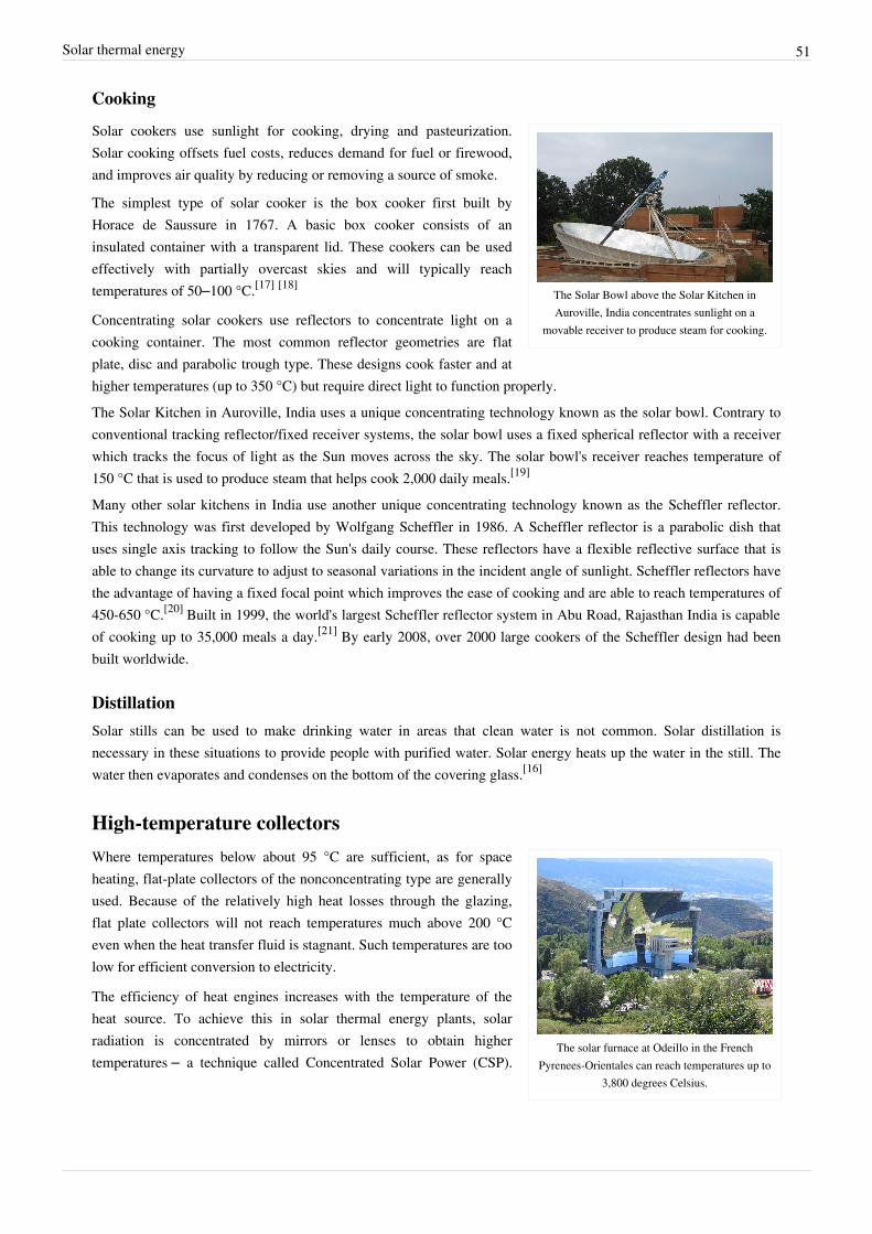
Solar thermal energy 51
Cooking
The Solar Bowl above the Solar Kitchen inAuroville, India concentrates sunlight on a
movable receiver to produce steam for cooking.
Solar cookers use sunlight for cooking, drying and pasteurization.Solar cooking offsets fuel costs, reduces demand for fuel or firewood,and improves air quality by reducing or removing a source of smoke.
The simplest type of solar cooker is the box cooker first built byHorace de Saussure in 1767. A basic box cooker consists of aninsulated container with a transparent lid. These cookers can be usedeffectively with partially overcast skies and will typically reachtemperatures of 50–100 °C.[17] [18]
Concentrating solar cookers use reflectors to concentrate light on acooking container. The most common reflector geometries are flatplate, disc and parabolic trough type. These designs cook faster and athigher temperatures (up to 350 °C) but require direct light to function properly.The Solar Kitchen in Auroville, India uses a unique concentrating technology known as the solar bowl. Contrary toconventional tracking reflector/fixed receiver systems, the solar bowl uses a fixed spherical reflector with a receiverwhich tracks the focus of light as the Sun moves across the sky. The solar bowl's receiver reaches temperature of150 °C that is used to produce steam that helps cook 2,000 daily meals.[19]
Many other solar kitchens in India use another unique concentrating technology known as the Scheffler reflector.This technology was first developed by Wolfgang Scheffler in 1986. A Scheffler reflector is a parabolic dish thatuses single axis tracking to follow the Sun's daily course. These reflectors have a flexible reflective surface that isable to change its curvature to adjust to seasonal variations in the incident angle of sunlight. Scheffler reflectors havethe advantage of having a fixed focal point which improves the ease of cooking and are able to reach temperatures of450-650 °C.[20] Built in 1999, the world's largest Scheffler reflector system in Abu Road, Rajasthan India is capableof cooking up to 35,000 meals a day.[21] By early 2008, over 2000 large cookers of the Scheffler design had beenbuilt worldwide.
DistillationSolar stills can be used to make drinking water in areas that clean water is not common. Solar distillation isnecessary in these situations to provide people with purified water. Solar energy heats up the water in the still. Thewater then evaporates and condenses on the bottom of the covering glass.[16]
High-temperature collectors
The solar furnace at Odeillo in the FrenchPyrenees-Orientales can reach temperatures up to
3,800 degrees Celsius.
Where temperatures below about 95 °C are sufficient, as for spaceheating, flat-plate collectors of the nonconcentrating type are generallyused. Because of the relatively high heat losses through the glazing,flat plate collectors will not reach temperatures much above 200 °Ceven when the heat transfer fluid is stagnant. Such temperatures are toolow for efficient conversion to electricity.
The efficiency of heat engines increases with the temperature of theheat source. To achieve this in solar thermal energy plants, solarradiation is concentrated by mirrors or lenses to obtain highertemperatures – a technique called Concentrated Solar Power (CSP).

Solar thermal energy 52
Concentrated solar power plant using parabolictrough design.
The practical effect of high efficiencies is to reduce the plant's collectorsize and total land use per unit power generated, reducing theenvironmental impacts of a power plant as well as its expense.
As the temperature increases, different forms of conversion becomepractical. Up to 600 °C, steam turbines, standard technology, have anefficiency up to 41%. Above 600 °C, gas turbines can be moreefficient. Higher temperatures are problematic because differentmaterials and techniques are needed. One proposal for very hightemperatures is to use liquid fluoride salts operating between 700 °C to800 °C, using multi-stage turbine systems to achieve 50% or morethermal efficiencies.[22] The higher operating temperatures permit theplant to use higher-temperature dry heat exchangers for its thermal exhaust, reducing the plant's water use – criticalin the deserts where large solar plants are practical. High temperatures also make heat storage more efficient,because more watt-hours are stored per unit of fluid.
Since the CSP plant generates heat first of all, it can store the heat before conversion to electricity. With currenttechnology, storage of heat is much cheaper and more efficient than storage of electricity. In this way, the CSP plantcan produce electricity day and night. If the CSP site has predictable solar radiation, then the CSP plant becomes areliable power plant. Reliability can further be improved by installing a back-up system that uses fossil energy. Theback-up system can reuse most of the CSP plant, which decreases the cost of the back-up system.With reliability, unused desert, no pollution, and no fuel costs, the obstacles for large deployment for CSP are cost,aesthetics, land use and similar factors for the necessary connecting high tension lines. Although only a smallpercentage of the desert is necessary to meet global electricity demand, still a large area must be covered withmirrors or lenses to obtain a significant amount of energy. An important way to decrease cost is the use of a simpledesign.
System designsDuring the day the sun has different positions. If the mirrors or lenses do not move, then the focus of the mirrors orlenses changes. Therefore it seems unavoidable that there needs to be a tracking system that follows the position ofthe sun (for solar photovoltaic a solar tracker is only optional). The tracking system increases the cost andcomplexity. With this in mind, different designs can be distinguished in how they concentrate the light and track theposition of the sun.
Parabolic trough designs

Solar thermal energy 53
Sketch of a parabolic trough design. A change ofposition of the sun parallel to the receiver does
not require adjustment of the mirrors.
Parabolic trough power plants use a curved, mirrored trough whichreflects the direct solar radiation onto a glass tube containing a fluid(also called a receiver, absorber or collector) running the length of thetrough, positioned at the focal point of the reflectors. The trough isparabolic along one axis and linear in the orthogonal axis. For changeof the daily position of the sun perpendicular to the receiver, the troughtilts east to west so that the direct radiation remains focused on thereceiver. However, seasonal changes in the in angle of sunlight parallelto the trough does not require adjustment of the mirrors, since the lightis simply concentrated elsewhere on the receiver. Thus the troughdesign does not require tracking on a second axis.
The receiver may be enclosed in a glass vacuum chamber. The vacuumsignificantly reduces convective heat loss.A fluid (also called heat transfer fluid) passes through the receiver and becomes very hot. Common fluids aresynthetic oil, molten salt and pressurized steam. The fluid containing the heat is transported to a heat engine whereabout a third of the heat is converted to electricity.
Andasol 1 in Gaudix, Spain uses the Parabolic Trough design which consists of long parallel rows of modular solarcollectors. Tracking the sun from East to West by rotation on one axis, the high precision reflector panelsconcentrate the solar radiation coming directly from the sun onto an absorber pipe located along the focal line of thecollector. A heat transfer medium, a synthetic oil like in car engines, is circulated through the absorber pipes attemperatures up to 400 °C and generates live steam to drive the steam turbine generator of a conventional powerblock.
Concentrating solar power systems are a fastgrowing source of sustainable energy.
Full-scale parabolic trough systems consist of many such troughs laidout in parallel over a large area of land. Since 1985 a solar thermalsystem using this principle has been in full operation in California inthe United States. It is called the SEGS system.[23] Other CSP designslack this kind of long experience and therefore it can currently be saidthat the parabolic trough design is the most thoroughly proven CSPtechnology.
The Solar Energy Generating System (SEGS) is a collection of nineplants with a total capacity of 350MW. It is currently the largestoperational solar system (both thermal and non-thermal). A newer
plant is Nevada Solar One plant with a capacity of 64MW. Under construction are Andasol 1 and Andasol 2 in Spainwith each site having a capacity of 50MW. Note however, that those plants have heat storage which requires a largerfield of solar collectors relative to the size of the steam turbine-generator to store heat and send heat to the steamturbine at the same time. Heat storage enables better utilization of the steam turbine. With day and some nighttimeoperation of the steam-turbine Andasol 1 at 50MW peak capacity produces more energy than Nevada Solar One at64 MW peak capacity, due to the former plant's thermal energy storage system and larger solar field.
553MW new capacity is proposed in Mojave Solar Park, California.[24] Furthermore, 59MW hybrid plant with heatstorage is proposed near Barstow, California.[25] Near Kuraymat in Egypt, some 40MW steam is used as input for agas powered plant.[26] [27] Finally, 25MW steam input for a gas power plant in Hassi R'mel, Algeria.[28]

Solar thermal energy 54
Power tower designs
Solar Two. Flat mirrors focus the light on the topof the tower. The white surfaces below thereceiver are used for calibrating the mirror
positions.
eSolar's 5 MW Sierra SunTower facility featuresarrays of heliostats (mirrors with sun-trackingmotion) to concentrate sunlight on to a centralreceiver mounted at the top of a tower. SierraSunTower is located in Lancaster, California.
Power towers (also known as 'central tower' power plants or 'heliostat'power plants) capture and focus the sun's thermal energy withthousands of tracking mirrors (called heliostats) in roughly a twosquare mile field. A tower resides in the center of the heliostat field.The heliostats focus concentrated sunlight on a receiver which sits ontop of the tower. Within the receiver the concentrated sunlight heatsmolten salt to over 1000 °F (538 °C). The heated molten salt thenflows into a thermal storage tank where it is stored, maintaining 98%thermal efficiency, and eventually pumped to a steam generator. Thesteam drives a standard turbine to generate electricity. This process,also known as the "Rankine cycle" is similar to a standard coal-firedpower plant, except it is fueled by clean and free solar energy.
The advantage of this design above the parabolic trough design is thehigher temperature. Thermal energy at higher temperatures can beconverted to electricity more efficiently and can be more cheaplystored for later use. Furthermore, there is less need to flatten theground area. In principle a power tower can be built on a hillside.Mirrors can be flat and plumbing is concentrated in the tower. Thedisadvantage is that each mirror must have its own dual-axis control,while in the parabolic trough design one axis can be shared for a largearray of mirrors.
Some or all of the following reads like a press release orcommercial promotion, please assist by rewriting, simplifying,and trimming as needed
SolarReserve, a Santa Monica, CA-based solar developer, uses thistechnology for the development of its concentrated solar thermal plantswith storage. The plants were designed by United TechnologiesCorporation. United Technologies' subsidiary, Rocketdyne,demonstrated the technology at the Solar One (1982–1986) and SolarTwo (1995–1999) power tower plants in Southern California, althoughthese plants were designed by the Department of Energy (DOE),Southern California Edison, LA Dept of Water and Power, andCalifornia Energy Commission. United Technologies has granted SolarReserve an exclusive worldwide license todevelop such power plants.
In November 2009, SolarReserve and a Madrid-based renewable energy developer, Preneal, received the keyenvironmental permit that is necessary for the construction of their 50 megawatt solar plant in Spain. This projectwill generate more than 300,000 megawatt hours of electricity per year, or enough electricity to power almost 70,000houses in the region. The Alcazar Solar Thermal Power Project will use molten salt as a coolant, which isexclusively licensed to SolarReserve by United Technologies Corporation (UTC).
In December 2009, SolarReserve announced two power contracts in the United States. The first was with Pacific Gas and Electric (PG&E) for the sale of electricity from SolarReserve's [29] Rice Solar Energy Project. The 150-megawatt solar energy project will be located 30 miles (48 km) northwest of the city of Blythe in eastern Riverside County, California. When completed, SolarReserve's facility will supply approximately 450,000 megawatt-hours annually of clean, reliable electricity – enough to power up to 68,000 homes during peak electricity

Solar thermal energy 55
periods – and will use thermal energy storage for nighttime power generation. The second power contract was a25-year power purchase agreement with NV Energy for the sale of electricity from SolarReserve's Crescent DunesSolar Energy Project. Developed and owned by SolarReserve's subsidiary, [30] Tonopah Solar Energy, LLC, theproject will be located near the town of Tonopah in Nye County, Nevada. When completed, Tonopah Solar Energy'sfacility will supply approximately 480,000 megawatt hours annually.In June 2008, eSolar [31], a Pasadena, CA-based company founded by Idealab CEO Bill Gross with funding fromGoogle [32], announced a power purchase agreement (PPA) with the utility Southern California Edison to produce245 megawatts of power [33]. Also, in February 2009, eSolar announced it had licensed its technology to twodevelopment partners, the Princeton, N.J.-based NRG Energy, Inc. [34], and the India-based ACME Group. In thedeal with NRG, the companies announced plans to jointly build 500 megawatts of concentrating solar thermal plantsthroughout the United States. The target goal for the ACME Group was nearly double; ACME plans [35] to startconstruction on its first eSolar power plant this year, and will build a total of 1 gigawatt over the next 10 years.eSolar's proprietary sun-tracking software coordinates the movement of 24,000 1 meter-square mirrors per 1 towerusing optical sensors [36] to adjust and calibrate the mirrors in real time. This allows for a high density of reflectivematerial which enables the development of modular concentrating solar thermal (CSP) power plants in 46 megawatt(MW) units on approximately π square mile parcels of land, resulting in a land-to-power ratio of 4 acres (16000 m2)per 1 megawatt.BrightSource Energy entered into a series of power purchase agreements with Pacific Gas and Electric Company inMarch 2008 for up to 900MW of electricity, the largest solar power commitment ever made by a utility.[37]
BrightSource is currently developing a number of solar power plants in Southern California, with construction of thefirst plant planned to start in 2009.In June 2008, BrightSource Energy dedicated its 4-6 MW [38] Solar Energy Development Center (SEDC) in Israel'sNegev Desert. The site, located in the Rotem Industrial Park, features more than 1,600 heliostats that track the sunand reflect light onto a 60 meter-high tower. The concentrated energy is then used to heat a boiler atop the tower to550 degrees Celsius, generating superheated steam.[39]
A working tower power plant is PS10 in Spain with a capacity of 11MW.The 15MW Solar Tres plant with heat storage is under construction in Spain. In South Africa, a 100MW solar powerplant is planned with 4000 to 5000 heliostat mirrors, each having an area of 140 m².[40] A 10MW power plant inCloncurry, Australia (with purified graphite as heat storage located on the tower directly by the receiver).[41]
Out of commission are the 10MW Solar One (later redeveloped and made into Solar Two) and the 2MW Themisplants.A cost/performance comparison between power tower and parabolic trough concentrators was made by the NRELwhich estimated that by 2020 electricity could be produced from power towers for 5.47 ₡/kWh and for 6.21 ₡/kWhfrom parabolic troughs. The capacity factor for power towers was estimated to be 72.9% and 56.2% for parabolictroughs.[42] There is some hope that the development of cheap, durable, mass producible heliostat power plantcomponents could bring this cost down.[43]

Solar thermal energy 56
Dish designs
A parabolic solar dish concentrating the sun'srays on the heating element of a Stirling engine.
The entire unit acts as a solar tracker.
A dish system uses a large, reflective, parabolic dish (similar in shapeto satellite television dish). It focuses all the sunlight that strikes thedish up onto to a single point above the dish, where a receiver capturesthe heat and transforms it into a useful form. Typically the dish iscoupled with a Stirling engine in a Dish-Stirling System, but alsosometimes a steam engine is used.[44] These create rotational kineticenergy that can be converted to electricity using an electricgenerator.[45]
The advantage of a dish system is that it can achieve much highertemperatures due to the higher concentration of light (as in towerdesigns). Higher temperatures leads to better conversion to electricityand the dish system is very efficient on this point. However, there arealso some disadvantages. Heat to electricity conversion requiresmoving parts and that results in maintenance. In general, a centralized approach for this conversion is better than thedencentralized concept in the dish design. Second, the (heavy) engine is part of the moving structure, which requiresa rigid frame and strong tracking system. Furthermore, parabolic mirrors are used instead of flat mirrors and trackingmust be dual-axis.In 2005 Southern California Edison announced an agreement to purchase solar powered Stirling engines fromStirling Energy Systems over a twenty year period and in quantities (20,000 units) sufficient to generate 500megawatts of electricity.[46] Stirling Energy Systems announced another agreement with San Diego Gas & Electricto provide between 300 and 900 megawatts of electricity.[47] In January 2010, Stirling Energy Systems and TesseraSolar commissioned the first demonstration 1.5-megawatt power plant ("Maricopa Solar") using Stirling technologyin Peoria, Arizona.[48]
Fresnel reflectors
Wind load is avoided by the low position of themirrors. Light construction of tracking system
due to separation from the receiver.
A linear Fresnel reflector power plant uses a series of long, narrow,shallow-curvature (or even flat) mirrors to focus light onto one or morelinear receivers positioned above the mirrors. On top of the receiver asmall parabolic mirror can be attached for further focusing the light.These systems aim to offer lower overall costs by sharing a receiverbetween several mirrors (as compared with trough and dish concepts),while still using the simple line-focus geometry with one axis fortracking. This is similar to the trough design (and different from centraltowers and dishes with dual-axis). The receiver is stationary and sofluid couplings are not required (as in troughs and dishes). The mirrorsalso do not need to support the receiver, so they are structurallysimpler. When suitable aiming strategies are used (mirrors aimed atdifferent receivers at different times of day), this can allow a denser packing of mirrors on available land area.
Recent prototypes of these types of systems have been built in Australia (CLFR[49] ) and by Solarmundo in Belgium.The Solarmundo research and development project, with its pilot plant at Liège, was closed down after successfulproof of concept of the Linear Fresnel technology. Subsequently, Solar Power Group GmbH (SPG [50]), based inMunich, Germany, was founded by some Solarmundo team members. A Fresnel-based prototype with direct steamgeneration was built by SPG in conjunction with the German Aerospace Center (DLR[51] ).

Solar thermal energy 57
Based on the Australian prototype, a 177MW plant had been proposed near San Luis Obispo in California and wouldbe built by Ausra.[52] But Ausra sold its planned California solar farm to First Solar. First Solar will not build theCarrizo project, and the deal has resulted in the cancellation of Ausra’s contract to provide 177 megawatts to P.G.&E.[53] Small capacity plants are an enormous economical challenge with conventional parabolic trough and drivedesign – few companies build such small projects. There are plans for SHP Europe, former Ausra subsidiary, tobuild a 6.5 MW combined cycle plant in Portugal. The German company SK Energy[54] ]) has plans to build severalsmall 1-3 MW plants in Southern Europe (esp. in Spain) using Fresnel mirror and steam drive technology (PressRelease[55] ).In May 2008, the German Solar Power Group GmbH and the Spanish Laer S.L. agreed the joint execution of a solarthermal power plant in central Spain. This will be the first commercial solar thermal power plant in Spain based onthe Fresnel collector technology of the Solar Power Group. The planned size of the power plant will be 10 MW asolar thermal collector field with a fossil co-firing unit as backup system. The start of constructions is planned for2009. The project is located in Gotarrendura, a small renewable energy pioneering village, about 100 km northwestof Madrid, Spain.A Multi-Tower Solar Array (MTSA) concept, that uses a point-focus Fresnel reflector idea, has also beendeveloped,[56] but has not yet been prototyped.Since March 2009, the Fresnel solar power plant PE 1 of the German company Novatec Biosol is in commercialoperation in southern Spain . The solar thermal power plant is based on linear Fresnel collector technology and hasan electrical capacity of 1.4 MW. Beside a conventional power block, PE 1 comprises a solar boiler with mirrorsurface of around 18,000m². The steam is generated by concentrating direct solar irradiation onto a linear receiverwhich is 7.40m above the ground. An absorber tube is positioned in the focal line of the mirror field in which wateris evaporated directly into saturated steam at 270 °C and at a pressure of 55 bar by the concentrated solar energy.
Linear Fresnel reflector technologies
Fresnel solar power plant PE 1 in southern Spain
Rival single axis tracking technologies include the relatively new linearFresnel reflector (LFR) and compact-LFR (CLFR) technologies. TheLFR differs from that of the parabolic trough in that the absorber isfixed in space above the mirror field. Also, the reflector is composed ofmany low row segments, which focus collectively on an elevated longtower receiver running parallel to the reflector rotational axis.[57]
This system offers a lower cost solution as the absorber row is sharedamong several rows of mirrors. However, one fundamental difficultywith the LFR technology is the avoidance of shading of incoming solarradiation and blocking of reflected solar radiation by adjacentreflectors. Blocking and shading can be reduced by using absorber towers elevated higher or by increasing theabsorber size, which allows increased spacing between reflectors remote from the absorber. Both these solutionsincrease costs, as larger ground usage is required.The CLFR offers an alternate solution to the LFR problem. The classic LFR has only one linear absorber on a singlelinear tower. This prohibits any option of the direction of orientation of a given reflector. Since this technologywould be introduced in a large field, one can assume that there will be many linear absorbers in the system.Therefore, if the linear absorbers are close enough, individual reflectors will have the option of directing reflectedsolar radiation to at least two absorbers. This additional factor gives potential for more densely packed arrays, sincepatterns of alternative reflector inclination can be set up such that closely packed reflectors can be positioned withoutshading and blocking.[58]
CLFR power plants offer reduced costs in all elements of the solar array.[58] These reduced costs encourage the advancement of this technology. Features that enhance the cost effectiveness of this system compared to that of the

Solar thermal energy 58
parabolic trough technology include minimized structural costs, minimized parasitic pumping losses, and lowmaintenance. Minimized structural costs are attributed to the use of flat or elastically curved glass reflectors insteadof costly sagged glass reflectors are mounted close to the ground. Also, the heat transfer loop is separated from thereflector field, avoiding the cost of flexible high pressure lines required in trough systems. Minimized parasiticpumping losses are due to the use of water for the heat transfer fluid with passive direct boiling. The use ofglass-evacuated tubes ensures low radiative losses and is inexpensive. Studies of existing CLFR plants have beenshown to deliver tracked beam to electricity efficiency of 19% on an annual basis as a preheater.[57]
Fresnel lenses
Prototypes of Fresnel lens concentrators have been produced for the collection of thermal energy by InternationalAutomated Systems [59]. No full-scale thermal systems using Fresnel lenses are known to be in operation, althoughproducts incorporating Fresnel lenses in conjunction with photovoltaic cells are already available.[60]
The advantage of this design is that lenses are cheaper than mirrors. Furthermore, if a material is chosen that hassome flexibility, then a less rigid frame is required to withstand wind load. A new concept of a lightweight,'non-disruptive' solar concentrator technology using asymmetric Fresnel lenses that occupies minimal ground surfacearea and allows for large amounts of concentrated solar energy per concentrator is seen in the 'Desert Blooms' [61]
project, though a prototype has yet to be made.
MicroCSP
"MicroCSP"[62] [63] references solar thermal technologies in which concentrating solar power (CSP) collectors arebased on the designs used in traditional Concentrating Solar Power systems found in the Mojave Desert[64] but aresmaller in collector size, lighter and operate at lower thermal temperatures usually below 315 °C (600 °F). Thesesystems are designed for modular field or rooftop installation where they are easy to protect from high winds, snowand humid deployments.[65] Solar manufacturer Sopogy completed construction on a 1MW CSP plant at the NaturalEnergy Laboratory of Hawaii.[66]
MicroCSP is used for community-sized power plants (1MW to 50MW), for industrial, agricultural andmanufacturing 'process heat' applications, and when large amounts of hot water are needed, such as resort swimmingpools, water parks, large laundry facilities, sterilization, distillation and other such uses.
Heat exchangeHeat in a solar thermal system is guided by five basic principles: heat gain; heat transfer; heat storage; heat transport;and heat insulation.[67] Here, heat is the measure of the amount of thermal energy an object contains and isdetermined by the temperature, mass and specific heat of the object. Solar thermal power plants use heat exchangersthat are designed for constant working conditions, to provide heat exchange.Heat gain is the heat accumulated from the sun in the system. Solar thermal heat is trapped using the greenhouseeffect; the greenhouse effect in this case is the ability of a reflective surface to transmit short wave radiation andreflect long wave radiation. Heat and infrared radiation (IR) are produced when short wave radiation light hits theabsorber plate, which is then trapped inside the collector. Fluid, usually water, in the absorber tubes collect thetrapped heat and transfer it to a heat storage vault.Heat is transferred either by conduction or convection. When water is heated, kinetic energy is transferred byconduction to water molecules throughout the medium. These molecules spread their thermal energy by conductionand occupy more space than the cold slow moving molecules above them. The distribution of energy from the risinghot water to the sinking cold water contributes to the convection process. Heat is transferred from the absorber platesof the collector in the fluid by conduction. The collector fluid is circulated through the carrier pipes to the heattransfer vault. Inside the vault, heat is transferred throughout the medium through convection.

Solar thermal energy 59
Heat storage enables solar thermal plants to produce electricity during hours without sunlight. Heat is transferred to athermal storage medium in an insulated reservoir during hours with sunlight, and is withdrawn for power generationduring hours lacking sunlight. Thermal storage mediums will be discussed in a heat storage section. Rate of heattransfer is related to the conductive and convection medium as well as the temperature differences. Bodies with largetemperature differences transfer heat faster than bodies with lower temperature differences.Heat transport refers to the activity in which heat from a solar collector is transported to the heat storage vault. Heatinsulation is vital in both heat transport tubing as well as the storage vault. It prevents heat loss, which in turn relatesto energy loss, or decrease in the efficiency of the system.
Heat storageHeat storage allows a solar thermal plant to produce electricity at night and on overcast days. This allows the use ofsolar power for baseload generation as well as peak power generation, with the potential of displacing both coal andnatural gas fired power plants. Additionally, the utilization of the generator is higher which reduces cost.Heat is transferred to a thermal storage medium in an insulated reservoir during the day, and withdrawn for powergeneration at night. Thermal storage media include pressurized steam, concrete, a variety of phase change materials,and molten salts such as sodium and potassium nitrate.[68] [69]
Steam accumulatorThe PS10 solar power tower stores heat in tanks as pressurized steam at 50 bar and 285 °C. The steam condenses andflashes back to steam, when pressure is lowered. Storage is for one hour. It is suggested that longer storage ispossible, but that has not been proven yet in an existing power plant.[70]
Molten salt storageA variety of fluids have been tested to transport the sun's heat, including water, air, oil, and sodium, but molten saltwas selected as best. Molten salt is used in solar power tower systems because it is liquid at atmosphere pressure, itprovides an efficient, low-cost medium in which to store thermal energy, its operating temperatures are compatiblewith today's high-pressure and high-temperature steam turbines, and it is non-flammable and nontoxic. In addition,molten salt is used in the chemical and metals industries as a heat-transport fluid, so experience with molten-saltsystems exists in non-solar settings.The molten salt is a mixture of 60 percent sodium nitrate and 40 percent potassium nitrate, commonly calledsaltpeter. New studies show that calcium nitrate could be included in the salts mixture to reduce costs and withtechnical benefits. The salt melts at 220 °C (430 °F) and is kept liquid at 290 °C (550 °F) in an insulated storagetank. The uniqueness of this solar system is in de-coupling the collection of solar energy from producing power,electricity can be generated in periods of inclement weather or even at night using the stored thermal energy in thehot salt tank. Normally tanks are well insulated and can store energy for up to a week. As an example of their size,tanks that provide enough thermal storage to power a 100-megawatt turbine for four hours would be about 9 m(30 ft) tall and 24 m (80 ft) in diameter.The Andasol power plant in Spain is the first commercial solar thermal power plant to utilize molten salt for heatstorage and nighttime generation. It came online March 2009.[71]

Solar thermal energy 60
Graphite heat storageDirectThe proposed power plant in Cloncurry Australia will store heat in purified graphite. The plant has a power towerdesign. The graphite is located on top of the tower. Heat from the heliostats goes directly to the storage. Heat forenergy production is drawn from the graphite. This simplifies the design.[72]
IndirectMolten salt coolants are used to transfer heat from the reflectors to heat storage vaults. The heat from the salts aretransferred to a secondary heat transfer fluid via a heat exchanger and then to the storage media, or alternatively, thesalts can be used to directly heat graphite. Graphite is used as it has relatively low costs and compatibility with liquidfluoride salts. The high mass and volumetric heat capacity of graphite provide an efficient storage medium.[73]
Phase-change materials for storagePhase Change Material (PCMs) offer an alternate solution in energy storage. Using a similar heat transferinfrastructure, PCMs have the potential of providing a more efficient means of storage. PCMs can be either organicor inorganic materials. Advantages of organic PCMs include no corrosives, low or no undercooling, and chemicaland thermal stability. Disadvantages include low phase-change enthalpy, low thermal conductivity, andflammability. Inorganics are advantageous with greater phase-change enthalpy, but exhibit disadvantages withundercooling, corrosion, phase separation, and lack of thermal stability. The greater phase-change enthalpy ininorganic PCMs make hydrate salts a strong candidate in the solar energy storage field.[74]
Use of waterA design which requires water for condensation or cooling may conflict with location of solar thermal plants indesert areas with good solar radiation but limited water resources. The conflict is illustrated by plans of SolarMillennium, a German company, to build a plant in the Amargosa Valley of Nevada which would require 20% of thewater available in the area. Some other projected plants by the same and other companies in the Mojave Desert ofCalifornia may also be affected by difficulty in obtaining adequate and appropriate water rights. California water lawcurrently prohibits use of potable water for cooling.[75]
Other designs require less water. The proposed Ivanpah Solar Power Facility in south-eastern California willconserve scarce desert water by using air-cooling to convert the steam back into water. Compared to conventionalwet-cooling, this results in a 90 percent reduction in water usage . The water is then returned to the boiler in a closedprocess which is environmentally friendly.[76]
Conversion rates from solar energy to electrical energyOf all of these technologies the solar dish/stirling engine has the highest energy efficiency. A single solardish-Stirling engine installed at Sandia National Laboratories National Solar Thermal Test Facility produces as muchas 25 kW of electricity, with a conversion efficiency of 31.25%.[77]
Solar parabolic trough plants have been built with efficiencies of about 20%. Fresnel reflectors have an efficiencythat is slightly lower (but this is compensated by the denser packing).The gross conversion efficiencies (taking into account that the solar dishes or troughs occupy only a fraction of thetotal area of the power plant) are determined by net generating capacity over the solar energy that falls on the totalarea of the solar plant. The 500-megawatt (MW) SCE/SES plant would extract about 2.75% of the radiation (1kW/m²; see Solar power for a discussion) that falls on its 4,500 acres (18.2 km²).[78] For the 50 MW AndaSol PowerPlant[79] that is being built in Spain (total area of 1,300×1,500 m = 1.95 km²) gross conversion efficiency comes outat 2.6%

Solar thermal energy 61
Furthermore, efficiency does not directly relate to cost: on calculating total cost, both efficiency and the cost ofconstruction and maintenance should be taken into account.
Levelised costSince a solar power plant does not use any fuel, the cost consists mostly of capital cost with minor operational andmaintenance cost. If the lifetime of the plant and the interest rate is known, then the cost per kWh can be calculated.This is called the levelised energy cost.The first step in the calculation is to determine the investment for the production of 1 kWh in a year. Example, thefact sheet of the Andasol 1 project shows a total investment of 310 million euros for a production of 179 GWh ayear. Since 179 GWh is 179 million kWh, the investment per kWh a year production is 310 / 179 = 1.73 euro.Another example is Cloncurry solar power station in Australia. It is planned to produce 30 million kWh a year for aninvestment of 31 million Australian dollars. So, if this is achieved in reality, the cost would be 1.03 Australian dollarfor the production of 1 kWh in a year. This would be significantly cheaper than Andasol 1, which can partially beexplained by the higher radiation in Cloncurry over Spain. The investment per kwh cost for one year should not beconfused with the cost per kwh over the complete lifetime of such a plant.In most cases the capacity is specified for a power plant (for instance Andasol 1 has a capacity of 50MW). Thisnumber is not suitable for comparison, because the capacity factor can differ. If a solar power plant has heat storage,then it can also produce output after sunset, but that will not change the capacity factor, it simply displaces theoutput. The average capacity factor for a solar power plant, which is a function of tracking, shading and location, isabout 20%, meaning that a 50MW capacity power plant will typically provide a yearly output of 50 MW × 24 hrs ×365 days × 20% = 87,600 MWh/year, or 87.6 GWh/yr.Although the investment for one kWh year production is suitable for comparing the price of different solar powerplants, it does not give the price per kWh yet. The way of financing has a great influence on the final price. If thetechnology is proven, an interest rate of 7%[80] should be possible. However, for a new technology investors want amuch higher rate to compensate for the higher risk. This has a significant negative effect on the price per kWh.Independent of the way of financing, there is always a linear relation between the investment per kWh production ina year and the price for 1 kWh (before adding operational and maintenance cost). In other words, if by enhancementsof the technology the investments drop by 20%, then the price per kWh also drops by 20%.If a way of financing is assumed where the money is borrowed and repaid every year, in such way that the debt andinterest decreases, then the following formula can be used to calculate the division factor: (1 - (1 + interest / 100) ^-lifetime) / (interest / 100). For a lifetime of 25 years and an interest rate of 7%, the division factor is 11.65. Forexample, the investment of Andasol 1 was 1.73 euro per kWh, divided by 11.65 results in a price of 0.15 euro perkWh. If one cent operation and maintenance cost is added, then the levelized cost is 0.16 euro per kWh. Other waysof financing, different way of debt repayment, different lifetime expectation, different interest rate, may lead to asignificantly different number.If the cost per kWh may follow the inflation, then the inflation rate can be added to the interest rate. If an investorputs his money on the bank for 7%, then he is not compensated for inflation. However, if the cost per kWh is raisedwith inflation, then he is compensated and he can add 2% (a normal inflation rate) to his return. The Andasol 1 planthas a guaranteed feed-in tariff of 0.21 euro for 25 years. If this number is fixed, after 25 years with 2% inflation, 0.21euro will have a value comparable with 0.13 euro now.Finally, there is some gap between the first investment and the first production of electricity. This increases theinvestment with the interest over the period that the plant is not active yet. The modular solar dish (but also solarphotovoltaic and wind power) have the advantage that electricity production starts after first construction.Given the fact that solar thermal power is reliable, can deliver peak load and does not cause pollution, a price of US$0.10 per kWh[81] starts to become competitive. Although a price of US$0.06 has been claimed[82] With some

Solar thermal energy 62
operational cost a simple target is 1 dollar (or lower) investment for 1 kWh production in a year.
Standards• EN 12975 (efficiency test)
References[1] "It's solar power's time to shine" (http:/ / articles. moneycentral. msn. com/ Investing/ SuperModels/ ItsSolarPowersTimeToShine.
aspx?page=1). MSN Money. . Retrieved 2008-06-05.[2] Manning, Paddy (10 October 2009). "With green power comes great responsibility" (http:/ / www. smh. com. au/ business/
with-green-power-comes-great-responsibility-20091009-gqvt. html). Sydney Morning Herald. . Retrieved 2009-10-12.[3] EIA Renewable Energy- Shipments of Solar Thermal Collectors by Market Sector, End Use, and Type (http:/ / www. eia. doe. gov/ cneaf/
solar. renewables/ page/ solarreport/ table2_10. html)[4] "Energy Consumption Characteristics of Commercial Building HVAC Systems" (http:/ / web. archive. org/ web/ 20080410212543/ http:/ /
www. eere. energy. gov/ buildings/ info/ documents/ pdfs/ hvacvolume1finalreport. pdf) (PDF). United States Department of Energy. pp. 1–6,2-1. Archived from the original (http:/ / www. eere. energy. gov/ buildings/ info/ documents/ pdfs/ hvacvolume1finalreport. pdf) on2008-04-10. . Retrieved 2008-04-09.
[5] Apte, J. et al.. "Future Advanced Windows for Zero-Energy Homes" (http:/ / windows. lbl. gov/ adv_Sys/ ASHRAE Final DynamicWindows. pdf) (PDF). ASHRAE. . Retrieved 2008-04-09.
[6] "Indirect Gain (Trombe Walls)" (http:/ / www. eere. energy. gov/ consumer/ your_home/ designing_remodeling/ index. cfm/mytopic=10300). United States Department of Energy. . Retrieved 2007-09-29.
[7] Douglass, Elizabeth (2007-11-10). "His passion for solar still burns" (http:/ / web. archive. org/ web/ 20071215081145/ http:/ / www. latimes.com/ business/ la-fi-haroldhay10nov10,1,5782216. story?coll=la-headlines-business). Los Angeles Times. Archived from the original (http:/ /www. latimes. com/ business/ la-fi-haroldhay10nov10,1,5782216. story?coll=la-headlines-business) on 2007-12-15. . Retrieved 2007-11-14.
[8] Butti and Perlin (1981), p.72[9] http:/ / www. nrel. gov/ learning/ re_solar_process. html[10] Bartlett (1998), p.393-394[11] Leon (2006), p.62[12] "Solar Buildings (Transpired Air Collectors – Ventilation Preheating)" (http:/ / www. nrel. gov/ docs/ fy06osti/ 29913. pdf) (PDF). National
Renewable Energy Laboratory. . Retrieved 2007-09-29.[13] "Frito-Lay solar system puts the sun in SunChips, takes advantage of renewable energy" (http:/ / www. modbee. com/ 1618/ story/ 259206.
html). The Modesto Bee. . Retrieved 2008-04-25.[14] Denholm, P. (March 2007) (PDF). The Technical Potential of Solar Water Heating to Reduce Fossil Fuel Use and Greenhouse Gas
Emissions in the United States (http:/ / www. nrel. gov/ docs/ fy07osti/ 41157. pdf). National Renewable Energy Laboratory. . Retrieved2007-12-28.
[15] Kincaid, J. (May 2006). Durham Campaign for Solar Jobs (http:/ / web. archive. org/ web/ 20070715053709/ http:/ / www.cleanenergydurham. org/ why/ solarjobreport. doc). Archived from the original (http:/ / www. cleanenergydurham. org/ why/ solarjobreport.doc) on 2007-07-15. . Retrieved 2007-12-28.
[16] "Solar Thermal Energy" (http:/ / practicalaction. org/ icts/ docs/ technical_information_service/ solar_thermal_energy. pdf). . Retrieved Oct.8, 2009.
[17] Butti and Perlin (1981), p.54-59[18] "Design of Solar Cookers" (http:/ / www. azsolarcenter. com/ technology/ solcook-4. html). Arizona Solar Center. . Retrieved 2007-09-30.[19] "The Solar Bowl" (http:/ / www. auroville. org/ research/ ren_energy/ solar_bowl. htm). Auroville Universal Township. . Retrieved
2008-04-25.[20] "Scheffler-Reflector" (http:/ / www. solare-bruecke. org/ English/ scheffler_e-Dateien/ scheffler_e. htm). Solare Bruecke. . Retrieved
2008-04-25.[21] "Solar Steam Cooking System" (http:/ / web. archive. org/ web/ 20071111132802/ http:/ / gadhia-solar. com/ products/ steam. htm). Gadhia
Solar. Archived from the original (http:/ / gadhia-solar. com/ products/ steam. htm) on 2007-11-11. . Retrieved 2008-04-25.[22] ORNL's liquid fluoride proposal. (http:/ / www. ornl. gov/ sci/ scale/ pubs/ SOL-05-1048_1. pdf)[23] SEGS system (http:/ / www. fplenergy. com/ portfolio/ contents/ segs_viii. shtml)[24] Israeli company to build largest solar park in world in US (http:/ / www. ynetnews. com/ articles/ 0,7340,L-3430085,00. html) Ynetnews, 26
July 2007.[25] Solar thermal electric hybrid power plant for barstow (http:/ / www. earthtoys. com/ news. php?section=view& id=3361)[26] Iberdrola to build 150MW Egyptian thermal solar plant (http:/ / www. bbj. hu/ main/ news_32058_iberdrola+ to+ build+ 150+ mw+
egyptian+ thermal+ solar+ plant. html)[27] Solar Millennium Tochter Flagsol erhält Auftrag für erstes Parabolrinnen-Kraftwerk Ägyptens (http:/ / www. faz. net/ d/ invest/ meldung.
aspx?id=62644991)

Solar thermal energy 63
[28] Abener Signs Contract for Solar Thermal Electric - Combined Cycle Hybrid Plant (http:/ / www. solarbuzz. com/ News/ NewsAFPR26.htm), Solarbuzz.com
[29] http:/ / www. ricesolarenergy. com/[30] http:/ / www. tonopahsolar. com/[31] http:/ / www. esolar. com/[32] http:/ / www. esolar. com/ news/ press/ 2009_01_23[33] http:/ / www. esolar. com/ news/ press/ 2008_06_03[34] http:/ / www. esolar. com/ news/ press/ 2009_02_23[35] http:/ / www. esolar. com/ news/ press/ 2009_03_03[36] http:/ / www. esolar. com/ news/ press/ 2008_09_30[37] "BrightSource Energy signs whopper solar contract with PG&E" (http:/ / news. cnet. com/ 8301-11128_3-9907089-54. html). CNET News.
2008-03-31. . Retrieved 2008-06-11.[38] "SOLAR ENERGY DEVELOPMENT CENTER (SEDC) – NEGEV, ISRAEL" (http:/ / www. brightsourceenergy. com/ projects/ sedc).
BrightSource Energy. .[39] "BrightSource / Luz II Dedicate Negev Solar Energy Development Center" (http:/ / cleantech-israel. blogspot. com/ 2008/ 06/
brightsource-luz-ii-dedicate-negev. html). Cleantech Investing in Israel. 2008-06-12. . Retrieved 2008-06-12.[40] 100 MW Solar Thermal Electric Project in South Africa (http:/ / solar4africa. net/ news/ viewnews. php?ID=249)[41] Cloncurry to run on solar alone (http:/ / www. theage. com. au/ news/ National/ Cloncurry-to-run-on-solar-alone-Bligh/ 2007/ 11/ 04/
1194117867247. html)[42] Assessment of Parabolic Trough and Power Tower Solar Technology Cost and Performance Forecasts (http:/ / www. nrel. gov/ solar/
parabolic_trough. html)[43] Google's Goal: Renewable Energy Cheaper than Coal November 27, 2007 (http:/ / www. google. com/ intl/ en/ press/ pressrel/
20071127_green. html)[44] ANU 'Big Dish', http:/ / solar-thermal. anu. edu. au/[45] Stirling Energy Systems Inc. - Solar Overview (http:/ / www. stirlingenergy. com/ solar_overview. htm)[46] World's largest solar installation to use Stirling engine technology (http:/ / pesn. com/ 2005/ 08/ 11/ 9600147_Edison_Stirling_largest_solar/
)[47] Stirling Energy Systems Signs New Contract for 300 MW (http:/ / pesn. com/ 2005/ 10/ 12/ 9600186_Stirling_300MW/ )[48] O'Grady, Patrick (23 January 2010). "SES, Tessera debut new solar plant in Peoria" (http:/ / phoenix. bizjournals. com/ phoenix/ stories/
2010/ 01/ 18/ daily87. html). Phoenix Business Journal. . Retrieved June 17, 2010.[49] CLFR (http:/ / jpye. dyndns. org)[50] http:/ / www. solarpowergroup. com/[51] DLR - Institut für Technische Thermodynamik - Home (http:/ / www. dlr. de/ tt)[52] PG&E links with Ausra for 177 megawatts of solar thermal power (http:/ / www. news. com/ 8301-11128_3-9810199-54. html?part=rss&
subj=news& tag=2547-1009_3-0-10)[53] Ausra Sells Planned Plant to First Solar (http:/ / greeninc. blogs. nytimes. com/ 2009/ 11/ 05/ ausra-sells-planned-plant-to-first-solar/ )[54] SK Energy GmbH (http:/ / www. sk-energy. com)[55] SK Energy GmbH: neuer deutscher Hersteller steigt in den Markt für kleine bis mittelgroße solarthermische Kraftwerke ein (http:/ / www.
iwrpressedienst. de/ Textausgabe. php?id=2819)[56] Mills, D (January 2004). "Advances in solar thermal electricity technology". Solar Energy (Elsevier) 76 (1): 19.
doi:10.1016/S0038-092X(03)00102-6.[57] Mills, D. "Advances in Solar Thermal Electricity Technology." Solar Energy 76 (2004): 19-31. 28 May 2008.[58] Mills, D, and Morrison L. Graham. "Compact Linear Fresnel Reflector Solar Thermal Powerplants." Solar Energy 68 (2000): 263-283. 28
May 2008.[59] http:/ / iaus. com/ AdvancedSolarCollector. aspx[60] SunCube (http:/ / www. greenandgoldenergy. com. au/ )[61] Desert Blooms Land Art Generator Initiative Competition (http:/ / www. landartgenerator. org/ blagi/ archives/ 963)[62] http:/ / www. seia. org/ galleries/ pdf/ 2008_Year_in_Review_Slides. pdf[63] Hawaiian Firm Shrinks Solar Thermal Power (http:/ / www. news. com/ Hawaiian-firm-shrinks-solar-thermal-power/
2100-11392_3-6207877. html)[64] SEGS[65] MicroCSP in Idaho (http:/ / www. earthtoys. com/ news. php?section=view& id=2992)[66] (http:/ / www. hawaii247. org/ 2009/ 12/ 11/ sopogy-introduces-new-solar-technology-at-nelha/ )[67] Canivan, John. "Five Solar Thermal Principles." JC Solarhomes. 26 May 2008 <http://www.jc-solarhomes.com/five.htm>.[68] Sandia National Lab Solar Thermal Test Facility (http:/ / www. sandia. gov/ Renewable_Energy/ solarthermal/ NSTTF/ salt. htm)[69] National Renewable Energy Laboratory (http:/ / www. nrel. gov/ csp/ troughnet/ thermal_energy_storage. html)[70] Ausra (http:/ / www. sciam. com/ article. cfm?articleID=1FC8E87E-E7F2-99DF-3253ADDFDBEC8D41), article in Scientific American[71] (http:/ / www. solarmillennium. de/ front_content. php?idart=155& lang=2)[72] Lloyd Energy Storage (http:/ / www. lloydenergy. com/ ), see news, Cloncurry Solar Thermal Storage Project

Solar thermal energy 64
[73] Forsberg, Charles W., Per F. Peterson, and Haihua Zhao. "High Temperature Liquied Fluoride Salt Closed Brayton Cycle Solar PowerTowers." Journal of Solar Energy Engineering 129 (2007): 141
[74] Zalba, Belen, Jose M. Marin, Luisa F. Cabeza, and Harald Mehling. "Review on Thermal Energy Storage with Phase Change: Materials,Heat Transfer Analysis and Applications." Applied Thermal Engineering 23 (2003): 251-283.
[75] "Alternative Energy Projects Stumble on a Need for Water" (http:/ / www. nytimes. com/ 2009/ 09/ 30/ business/ energy-environment/30water. html) article by Todd Woody in The New York Times September 29, 2009
[76] BrightSource & Bechtel Partner on 440-MW Ivanpah CSP Project (http:/ / www. renewableenergyworld. com/ rea/ news/ article/ 2009/ 09/brightsource-bechtel-partner-on-440-mw-ivanpah-csp-project?cmpid=SolarNL-Tuesday-September15-2009) Renewable Energy World,September 10, 2009.
[77] Sandia National Laboratories (2008-02-12). "Sandia, Stirling Energy Systems set new world record for solar-to-grid conversion efficiency"(http:/ / www. sandia. gov/ news/ resources/ releases/ 2008/ solargrid. html). Press release. .
[78] Major New Solar Energy Project Announced By Southern California Edison and Stirling Energy Systems, Inc. (http:/ / www. hydrogennow.org/ HNews/ PressReleases/ SCE/ SCE-SES-Project. htm), press release
[79] 2x50 MW AndaSol Power Plant Projects in Spain (http:/ / www. solarpaces. org/ News/ Projects/ Spain. htm)[80] Solar Thermal Industry Needs Loan Guarantees (http:/ / earth2tech. com/ 2007/ 09/ 11/
ausra-chairman-solar-thermal-industry-needs-loan-guarantees/ )[81] "Under 10 cents is sort of the magic line" (http:/ / richardlalancette. blogspot. com/ 2007/ 07/ shrinking-cost-for-solar-power. html)[82] Development of Two Solar-thermal Electric Hybridized Power Plant Debuts in Southern California (http:/ / www. newswiretoday. com/
news/ 25722/ )
External links• Onsite Renewable Technologies (http:/ / www. epa. gov/ oaintrnt/ energy/ renewtech. htm) at United States
Environmental Protection Agency website• Renewable solar energy websites (http:/ / www. dmoz. org/ Science/ Technology/ Energy/ Renewable/ Solar/ ) at
the Open Directory Project• Assessment of the World Bank/GEF Strategy for the Market Development of Concentrating Solar Thermal Power
(http:/ / siteresources. worldbank. org/ GLOBALENVIRONMENTFACILITYGEFOPERATIONS/ Resources/Publications-Presentations/ SolarThermal. pdf)
• Concentrating Solar Power (http:/ / europe. theoildrum. com/ node/ 2583) An overview of the technology byGerry Wolff, coordinator of TREC-UK
• NREL Concentrating Solar Power Program Site (http:/ / www. nrel. gov/ csp)• Comprehensive review of parabolic trough technology and markets (http:/ / www. nrel. gov/ csp/ troughnet)• Nevada Gets First U.S. Solar Thermal Plant (http:/ / www. renewableenergyaccess. com/ rea/ news/
story?id=50850)

65
Tools
Architectural light shelfA light shelf is an architectural element that allows daylight to penetrate deep into a building. This horizontallight-reflecting overhang is placed above eye-level and has a high-reflectance upper surface. This surface is thenused to reflect daylight onto the ceiling and deeper into a space. Light shelves are generally made of an extrudedaluminium chassis system and aluminium composite panel surfaces. Extruded components can be painted oranodized and they are all field fabricated and assembled from stock lengths.Light shelves are typically used in high-rise and low-rise office buildings, as well as institutional buildings. Thisdesign is generally used on the equator-facing side of the building, which is where maximum sunlight is found, andas a result is most effective. Not only do light shelves allow light to penetrate through the building, they are alsodesigned to shade near the windows, due to the overhang of the shelf, and help reduce window glare. Exteriorshelves are generally more effective shading devices than interior shelves. A combination of exterior and interiorshelves will work best in providing an even illumination gradient. For maximum benefit, perimeter lighting shouldbe controlled by photo-sensors, with lighting zones appropriate to the particular installation
BenefitsArchitectural light shelves have been proven to reduce the amount of artificial lighting in a building. Since they canreflect light deeper into a space, the use of incandescent and fluorescent lighting can be reduced or completelyeliminated, depending on the space. Light shelves make it possible for daylight to penetrate the space up to 2.5 timesthe distance between the floor and the top of the window. Today, advanced light shelf technology makes it possibleto increase the distance up to 4 times. In spaces such as classrooms and offices, light shelves have been proven toincrease occupant comfort and productivity. Furthermore, incorporating light shelves in a building design isadmissible for the Leadership in Energy and Environmental Design point system, falling under the “IndoorEnvironment Quality: Daylight & Views” category.
AestheticsLight shelves integrate themselves with window designs or curtain wall systems which make them aestheticallypleasing. They are made of very light materials which make them visible but not distracting. The aluminiumcomposite panel surfaces can be painted or anodized, and can be ordered in various colours. Two options areavailable, the fascia cap and the continuous panel
LimitationsLight shelves may not be suitable for all climates. They are generally used in mild climates and not in tropical ordesert climates due to the intense solar heat gain. These hot climates, compared to mild climates, require very smallwindow openings to reduce the amount of heat infiltration.The fact that light shelves extend a fair distance into a room may result in interference with sprinkler systems. InCanada, they cannot exceed 1200 mm (4 ft.) in width if sprinklers are present or the design will require integrationwith sprinkler system to cover the floor area under the light shelf. They also require a higher than averagefloor-to-ceiling heights in order for them to be effective, or daylight may be inadvertently redirected into occupants'eyes.

Architectural light shelf 66
The distance into a space that light is cast is variable depending on both the time of day and the time of year.Light Shelves also increase maintenance requirements and window coverings must be coordinated with light shelfdesign.
AlternativesAlternatives to light shelves for window daylighting include blinds and louver systems, both of which can be interioror exterior.Blinds reduce solar gain, but do little to redirect light into the interior space.Exterior louver systems often rely on adjustments from either complex servo motors or building occupantsthroughout the day to operate well. Both of these systems can be unreliable at times, reducing the overall benefit ofhaving a daylighting system.Some newer products have found solutions to many of these problems. Products like LightLouver [1], which arehung on the inside of overhead windows, use fixed louvers with a complex geometry to redirect incoming daylightabove 5° onto an interior ceiling. The effect is much like that of a light shelf, only with much more consistentillumination.
References[1] http:/ / www. lightlouver. com
Roof lantern
Roof Lantern
Internal View of Roof Lantern
The term roof lantern in its most common use today describes amulti-paned glass structure that sits atop a typically flat roof in order toprovide natural light into the room below. A roof lantern is in effect askylight. The term has also been used (Roof Top Lantern) to describethe decorative lighted lanterns atop Japanese taxi cabs designed tomimic the cultural heritage of Japanese lanterns.
Roof lanterns derived from structures first built in 16th century Franceand Italy called Orangeries. Orangeries were brick or frame structureswith tall glass side windows and a central glass area in the flat roof foradded sunlight. Orangeries were built to grow fruit in non-temperateclimates. Orangeries today are considered a form or style ofconservatory. Roof lanterns today serve as an architectural featurebeyond the common version of commercial and plain skylights used oncountless homes and commercial structures. They allow for uniqueviews of the outdoors, and provide considerably more internal andexternal architectural appeal than common skylights, without the highcost of a full scale orangery or conservatory. Traditional architecturalstyles characterize most roof lanterns and the term is usedinterchangeably in the UK where roof lanterns are a common productin the building vernacular.
The first roof lanterns were made of timber and glass and were often prone to leaking.“Initially wood-framed in the 18th and 19th centuries, skylights became even more popular in metal construction with the advent of sheet-metal shops during the Victorian era. Virtually every urban row

Roof lantern 67
house of the late-19th and early-20th centuries relied upon a metal-framed skylight to illuminate itsenclosed stairwell. More elaborate dwellings of the era showed a fondness for the Roof Lantern, inwhich the humble ceiling-window design of the skylight is elaborated into a miniature glass-paneledconservatory-style roof cupola or tower” [1]
With advancements in glazing and sealing techniques, modern roof lanterns can have the same traditional look alongwith the benefits of high performance insulated glass and sealants, which reduce energy loss and providewater-tightness in the same manner as typical skylights. Today roof lanterns are built of both wood and aluminum,depending upon the style of building it is being added to and the owner’s personal preference.
References[1] ""Skylights & Roof Lanterns" (http:/ / www. period-homes. com/ ph3-sky. htm). .
OculusThis page is about the architectural term. See also: eye.
The Oculus (top) in the dome of thePantheon, Rome
An Oculus or circular window is a feature of Classical architecture since the16th century. They are often denoted by their French name, oeil de boeuf, or"bull's-eye". Such circular or oval windows express the presence of a mezzanineon a building's façade without competing for attention with the majorfenestration. Circular windows set in dormers have been a feature of FrenchClassical architecture since the beginning of the seventeenth century. Forstructural reasons, they are also found as the portholes of ships.
Oculus (plural oculi) is the Latin word for eye,[1] and the word remains in use incertain contexts, as the name of the round opening in the top of the dome of thePantheon in Rome,[2] and in reference to other round windows, openings, andskylights.
The Oculus in the Pantheon has always been open to the weather, allowing rainto enter and fall to the floor, where it is carried away through drains. In thepicture, right, sunlight streams through the opening and strikes the lower part ofthe dome. The bright opening and the surrounding smooth concrete above thecoffering resembles an eye, giving the opening its name.
In archaeology, oculus is the name given to a motif found in western European prehistoric art. It consists of a pair ofcircular or spiral marks, often interpreted as eyes, and appears on pottery, statues and megaliths. The oculus motifmay represent the watchful gaze of a god or goddess and was especially common during the Neolithic period.

Oculus 68
Notes[1] While oculus is not in common use in English, words derived from it such as ocular (relating to the eye) are, primarily in medical and optical
fields. Also, the terms Oculus Dexter (right eye), Oculus Sinister (left eye), and Oculus Uterque (both eyes) are used in medicine, usuallyabbreviated OD, OS, and OU, respectively.
[2] Since the revival of dome construction beginning in the Italian Renaissance, open oculi have been replaced by light-transmitting cupolas.
Effect of the view into a cupolathrough an oculus under natural
light (Wambierzyce, Poland)
Detail of oculus set in acartouche with the head ofMercury (Beaux-Arts New
York and New JerseyTelephone Company Building,
Brooklyn)
A bowl with two oculi fromthe Copper-Age site Los
Millares in Spain.
A porthole.
View of an oculus opening into acupola in the Hasht Behesht,
Isfahan

Light tube 69
Light tube
Light tubes
Light tubes or light pipes are used fortransporting or distributing natural orartificial light. In their application todaylighting, they are also often calledsun pipes, sun scopes, solar lightpipes, or daylight pipes.
Generally speaking, a light pipe orlight tube may refer to:
• a tube or pipe for transport of lightto another location, minimizing theloss of light;
• a transparent tube or pipe fordistribution of light over its length,either for equidistribution along theentire length (see also sulfur lamp)or for controlled light leakage.
Both have the purpose of lighting, for example in Architecture.
Materials and set-up
Light tube with reflective material
A light tube installed in the subterranean train station atPotsdamer Platz, Berlin, seen from above ...
Also known as a "tubular skylight", "SunScope" or "TubularDaylighting Device", this is the oldest and most widespread typeof light tube used for daylighting. The concept was originallydeveloped by the ancient Egyptians. The first commercial reflectorsystems were patented and marketed in the 1850s by Paul EmileChappuis in London, utilising various forms of angled mirrordesigns. Chappuis Ltd's reflectors were in continuous productionuntil the factory was destroyed in 1943.[1] The concept wasrediscovered and patented in 1986 by Solatube International ofAustralia.[2] This system has been marketed for widespreadresidential and commercial use. Other daylighting products are onthe market under various generic names, such as "SunScope","solar pipe", "light pipe", "light tube" and "tubular skylight".
A tube lined with highly reflective material leads the light raysthrough a building, starting from an entrance-point located on itsroof or one of its outer walls. A light tube is not intended forimaging (in contrast to a periscope, for example), thus imagedistortions pose no problem and are in many ways encouraged dueto the reduction of "directional" light.

Light tube 70
... and below ground.(More images on Wikimedia Commons)
The entrance point usually comprises a dome (cupola), which hasthe function of collecting and reflecting as much sunlight aspossible into the tube. Many units also have directional"collectors", "reflectors" or even Fresnel lens devices that assist incollecting additional directional light down the tube.
A set-up in which a laser cut acrylic panel is arranged to redirectsunlight into a horizontally or vertically orientated mirrored pipe,combined with a light spreading system with a triangulararrangement of laser cut panels that spread the light into the room,was developed at the Queensland University of Technology inBrisbane.[3] In 2003, Veronica Garcia Hansen, Ken Yeang, andIan Edmonds were awarded the Far East Economic ReviewInnovation Award in bronze for this development.[4] [5]
Light transmission efficiency is greatest if the tube is short andstraight. In longer, angled, or flexible tubes, part of the lightintensity is lost. To minimize losses, a high reflectivity of the tubelining is crucial; manufacturers claim reflectivities of theirmaterials, in the visible range, of up to 98 to almost 99.5percent.[6] [7]
At the end point (the point of use), a diffuser spreads the light intothe room.To further optimize the use of solar light, a heliostat can be installed which tracks the movement of the sun, therebydirecting sunlight into the light tube at all times of the day as far as the surroundings´ limitations allow, possibly withadditional mirrors or other reflective elements that influence the light path. The heliostat can be set to capturemoonlight at night.
Optical fiber
Optical fibers are well known as fiberscopes for imaging applications and as light guides for a wide range ofnon-imaging applications. In the latter context, they can also be used for daylighting: a solar lighting system basedon plastic optical fibers was in development at Oak Ridge National Laboratory in 2004;[8] [9] the system wasinstalled at the American Museum of Science and Energy, Tennessee, USA, in 2005,[10] and brought to market thesame year by the company Sunlight Direct.[11] [12]
A similar system, but using optical fibers of glass, had earlier been under study in Japan.[13]
In view of the usually small diameter of the fibers, an efficient daylighting set-up requires a parabolic collector totrack the sun and concentrate its light.Optical fibers intended for light transport need to propagate as much light as possible within the core; in contrast,optical fibers intended for light distribution are designed to let part of the light leak through their cladding.[14]

Light tube 71
Transparent hollow light guidesA prism light guide was developed in 1981[15] and has been used in solar lighting for both transport and distributionof light.[16] [17] A large solar pipe based on the same principle has been set up in a narrow courtyard of a 14-floorbuilding of a Washington D.C. law firm in 2001,[18] [19] [20] [21] [22] and a similar proposal has been made forLondon.[23] A further system has been installed in Berlin.[24]
The 3M company developed a system based on optical lighting film[25] and developed the 3M light pipe,[26] which isa light guide designed to distribute light uniformly over its length, with a thin film incorporating microscopicprisms,[15] which has been marketed in connection with artificial light sources, e.g. sulfur lamps.In contrast to an optical fiber which has a solid core, a prism light guide leads the light through air and is thereforereferred to as hollow light guide.The project ARTHELIO,[27] [28] partially funded by the European Commission, was an investigation in years 1998 to2000 into a system for adaptive mixing of solar and artificial light, and which includes a sulfur lamp, a heliostat, andhollow light guides for light transport and distribution.
Fluorescence based systemIn a system developed by Fluorosolar and the University of Technology, Sydney, two fluorescent polymer layers in aflat panel capture short wave sunlight, particularly ultraviolet light, generating red and green light, respectively,which is guided into the interior of a building. There, the red and green light is mixed with artificial blue light toyield white light, without infrared or ultraviolet. This system, which collects light without requiring mobile partssuch as a heliostat or a parabolic collector, is intended to transfer light to any place within a building. [29] [30] [31] Bycapturing ultraviolet the system can be especially effective on bright but overcast days; this since ultraviolet isdiminished less by cloud cover than are the visible components of sunlight.
Properties and applications
Solar and hybrid lighting systemsSolar light pipes, compared to conventional skylights and other windows, offer better heat insulation properties andmore flexibility for use in inner rooms, but less visual contact with the external environment.In the context of seasonal affective disorder, it may be worth consideration that an additional installation of lighttubes increases the amount of natural daily light exposure. It could thus possibly contribute to residents´ oremployees´ well-being while avoiding over-illumination effects.Compared to artificial lights, light tubes have the advantage of providing natural light and of saving energy. Thetransmitted light varies over the day; should this not be desired, light tubes can be combined with artificial light in ahybrid set-up.[16] [32] [33] [34]
Some artificial light sources are marketed which have a spectrum similar to that of sunlight, at least in the humanvisible spectrum range,[35] [36] [37] as well as low flicker.[37] Their spectrum can be made to vary dynamically such asto mimick the changes of natural light over the day. Manufacturers and vendors of such light sources claim that theirproducts can provide the same or similar health effects as natural light.[37] [38] [39] When considered as alternatives tosolar light pipes, such products may have lower installation costs but do consume energy during use; therefore theymay well be more wasteful in terms of overall energy resources and costs.On a more practical note, light tubes do not require electric installations or insulation, and are thus especially usefulfor indoor wet areas such as bathrooms and pools. From a more artistic point of view, recent developments,especially those pertaining to transparent light tubes, open new and interesting possibilities for architectural design.

Light tube 72
Security ApplicationsDue to the relatively small size and high light output of sun pipes, they have an ideal application to security orientedsituations, such as prisons, police cells and other locations where restricted access is required. Being of a narrowdiameter, and not largely affected by internal security grills, this provides daylight to areas without providingelectrical connections or escape access, and without allowing objects to be passed into a secure area.
Light tubes in electronic devicesMolded plastic light tubes are commonly used in the electronics industry to conduct illumination from LEDs on acircuit board to indicator symbols or buttons. These light tubes typically take on a highly complex shape that useseither gentle curving bends as in an optic fiber or have sharp prismatic folds which reflect off the angled corners.Multiple light tubes are often molded from a single piece of plastic, permitting easy device assembly since the longthin light tubes are all part of a single rigid component that snaps into place.Light tube indicators make electronics cheaper to manufacture since the old way would be to mount a tiny lamp intoa small socket directly behind the spot to be illuminated. This often requires extensive hand-labor for installation andwiring. Light tubes permit all lights to be mounted on a single flat circuit board, but the illumination can be directedup and away from the board by several inches, wherever it is required.
References[1] Science & Society Picture Library (http:/ / www. scienceandsociety. co. uk/ results. asp?image=10422108) Advertisement for Chappuis’
patent reflectors, c 1851-1870.[2] Solatube International, history (http:/ / www. solatube. com. au/ corporate/ about_history. php)[3] Ken Yeang: Light Pipes: An Innovative Design Device for Bringing Natural Daylight and Illumination into Buildings with Deep Floor Plan
(http:/ / www. trhamzahyeang. com/ features/ img/ Light pipe paper. pdf), Nomination for the Far East Economic Review Asian InnovationAwards 2003
[4] Lighting up your workplace — Queensland student pipes light to your office cubicle (http:/ / www. scienceinpublic. com/ freshinnovators/2005/ Veronica/ veronicagarciahansen. htm), May 9, 2005
[5] Kenneth Yeang (http:/ / www. worldcities. com. sg/ speaker3. htm#kenneth01), World Cities Summit 2008, June 23—25, 2008, Singapore[6] (http:/ / www. alanod. de/ opencms/ sites/ alanod. de/ de/ miro/ MIRO_Produkte/ MIRO_LIGHTPIPE/ index. html)[7] (French) http:/ / www. acoram. biz/ frtubelumiere. htm[8] Article on Hybrid Solar Lighting "Let the Sun Shine in", Discover Magazine, Vol. 25, No. 07, July 2004 (http:/ / www. ornl. gov/ sci/ solar/
pdfs/ Let the Sun Shine In. pdf)[9] ORNL - Solar Technologies Program (http:/ / www. ornl. gov/ sci/ solar/ )[10] HSL Featured in Popular Science's What's New Section (http:/ / www. popsci. com/ popsci/ whatsnew/
7b1f0e0796b84010vgnvcm1000004eecbccdrcrd. html) June 2005, Page 28[11] Oak Ridge National Laboratory - New Oak Ridge company putting hybrid solar lighting on map (http:/ / www. ornl. gov/ info/
press_releases/ get_press_release. cfm?ReleaseNumber=mr20050830-00)[12] Sunlight Direct- Architectural Design Information (http:/ / www. sunlight-direct. com/ overview. html)[13] Hybrid Solar Lighting: Bringing a little sunshine into our lives (http:/ / www. msnbc. msn. com/ id/ 7287168/ page/ 2/ ), MSNBC, March
2005[14] Use Of Diffusive Optical Fibers For Plant Lighting (http:/ / ncr101. montana. edu/ Light1994Conf/ 6_8_Kozai/ Kozai Fiber text. htm)[15] Use Of Prismatic Films To Control Light Distribution (http:/ / ncr101. montana. edu/ Light1994Conf/ 6_6_Kneipp/ Kneipp text. htm)[16] Solar Canopy Illumination: Solar Lighting at UBC (http:/ / www. physics. ubc. ca/ ssp/ research/ solarlighting. htm)[17] research frame (http:/ / www. physics. ubc. ca/ ssp/ ssp_research. htm#lightpipe)[18] Solar Light Pipe in Washington, D.C (http:/ / www. detail. de/ Archiv/ En/ HoleArtikel/ 5331/ Artikel)[19] IDOnline.com - The International Design Magazine - Graphic Design, Product Design, Architecture (http:/ / www. idonline. com/ adr03/
solar_contemp_eco. asp)[20] http:/ / www. bomin-solar. de/ Acrobat/ Heliostat/ H-4158-USA-Washington-SLP-2001. pdf[21] (German) http:/ / www. bomin-solar. de/ Acrobat/ Press/ DETAIL_4-04_SLP-Washington. pdf[22] "Solar Light Pipe in Washington, D.C.", DETAIL 4/2004, Building with light (http:/ / www. detail. de/
rw_5_Archive_En_HoleArtikel_5331_Artikel. htm)[23] Apple London - Special Ceiling (http:/ / carpenterlowings. com/ clad_projects_regent street. htm)[24] (German) "Tageslicht aus der Tube", Faktor Licht, Nr. 4, 2003 (http:/ / www. energie. gr. ch/ merkblatter/ faktorlicht04. pdf) (with a
description of the light pipe on Potsdamer Platz, Berlin)

Light tube 73
[25] Heliobus with 3M Optical Lighting Film (OLF) (http:/ / www. mmm. com/ intl/ CH/ english/ archive/ story4_980326. html)[26] 3M Light Management Solutions (US) (http:/ / cms. 3m. com/ cms/ US/ en/ 2-197/ krcziFU/ view. jhtml)[27] http:/ / erg. ucd. ie/ enerbuild/ pdfs/ ARTHELIO. pdf[28] (http:/ / www. iuav. it/ Didattica1/ pagine-web/ facolt--di/ Antonio-Ca/ master-pro/ Lux-Europa-2001. PDF)[29] Fluorosolar (http:/ / www. fluorosolar. com)[30] FluoroSolar - bringing the subshine inside (http:/ / www. treehugger. com/ files/ 2006/ 05/ fluorosolar_bri. php), Treehugger, February 5,
2006 (retrieved on January 13, 2007)[31] Video (http:/ / www. abc. net. au/ catalyst/ stories/ s1610451. htm) on fluorescence based system[32] Night Lite (http:/ / www. sunpipe. com/ NightLite. htm)[33] (http:/ / www. natural-light-skylights. com/ pages/ light_kit. html)[34] Sunlight Direct- Lighting Design Information (http:/ / www. sunlight-direct. com/ lighting. html)[35] True-Lite (http:/ / www. xternet. de/ bioelektrik/ en/ true-lite. htm)[36] "What is SoLux?" (http:/ / www. solux. net/ ). Solux.net. . Retrieved 2010-09-29.[37] (German) http:/ / www. e-wenzl. at/ lichtliteratur/ vollspektrum_001. html[38] (German) http:/ / www. j-lorber. de/ shm/ licht/ vollspektrum-bedeutg. htm[39] (German) http:/ / www. villiton. ch/ vollspektrumlicht. php
External links
Overview• Light Tubes on "Potsdamer Platz" are made by Heliobus AG Switzerland (http:/ / www. heliobus. com)• "Smart Lighting for a Smart House" (an overview over daylighting, listing also light pipes) - [1] , HTML (http:/ /
www. google. com/ search?q=cache:hfq4UoFXUMIJ:www. smarthouse. duke. edu/ downloads/smart_lighting_noor. ppt+ sunlight+ courtyard+ heliostat& hl=de& gl=de& ct=clnk& cd=1)
• Solar lighting (http:/ / www. fsec. ucf. edu/ BLDG/ ACTIVE/ fenestration/ solLighting/ index. htm) andIllumination of Buildings using Light Pipes (http:/ / www. fsec. ucf. edu/ BLDG/ ACTIVE/ fenestration/solLighting/ piped. htm), Florida Solar Energy Center (at the University of Central Florida)
• Daylighting Using Tubular Light Guide Systems (http:/ / etheses. nottingham. ac. uk/ archive/ 00000026/ 01/Thesis_-_Joel_Callow. pdf) (thesis)
• (German) an overview over light guidance - PDF (http:/ / bine. info/ pdf/ infoplus/ pro0100systematik. pdf),HTML (http:/ / www. google. com/ search?q=cache:yWQqhEXs2doJ:bine. info/ pdf/ infoplus/pro0100systematik. pdf+ "light+ pipe"+ 3M+ solar& hl=de& gl=de& ct=clnk& cd=4)
• "A Study of Performance of Light Pipes Under Cloudy and Sunny Conditions in the UK" (http:/ / www. google.com/ search?q=cache:p75yHX4tgw4J:www. iaeel. org/ iaeel/ archive/ right_light_proceedings/Proceedings_body/ BOK4/ RL4shao. pdf+ "light+ pipe"+ 3M+ solar& hl=de& gl=de& ct=clnk& cd=20)
• "Sunlight in a tube", World Science, 2005 (http:/ / www. world-science. net/ othernews/ 050310_suntubefrm.htm)
• A series of technical reference (http:/ / www. sunpipe. co. uk/ technical/ index. php) information pages from theUK, referring to installation and mounting information
• "Use of prismatic films to control light distribution", K. G. Kneipp, International Lighting in ControlledEnvironments Workshop, T.W.Tibbitts (editor), 1994, NASA-CP-95-3309 (http:/ / ncr101. montana. edu/Light1994Conf/ 6_6_Kneipp/ Kneipp text. htm) (with an overview on the piping of light)
• (German) Alexander Rosemann: Hohllichtleiter für Tageslichtnutzung. Pflaum Verlag, München 2002. ISBN3-7905-0862-4
• "A Design Tool for Predicting the Performances of Light Pipes" Jenkins et al. link title (http:/ / www.sciencedirect. com/ science?_ob=MImg& _imagekey=B6V2V-4DVTGNF-3-1& _cdi=5712& _user=273788&_orig=search& _coverDate=05/ 01/ 2005& _sk=999629994& view=c& _alid=448611134& _rdoc=34&wchp=dGLbVzz-zSkzk& md5=580292344ec5f606ba4c271817fa2ca2& ie=/ sdarticle. pdf)
• UK based Monodraught SunPipe (http:/ / www. sunpipe. co. uk/ sunpipe/ index. php) (and www.sunpipe.info)with extensive technical and reference information

Light tube 74
• UK based <http://www.glidevale.com/downloads/Sunscoop%20Tubular%20Rooflights.pdf> andwww.glidevail.com with extensive technical and reference information
• Monodraught (http:/ / www. monodraught. co. uk) SunPipe - the UK's largest and most successful vendor of LightTube products and solutions.
• Case study installing light tubes in an older residential bungalow (http:/ / www. humphrey-house. com/ search/label/ suntunnel)
Other approaches to sunlight capture and transmission• the Japanese approach of "depthscraper" (http:/ / blog. modernmechanix. com/ 2006/ 06/ 01/
depthscrapers-defy-earthquakes/ #more-715) : a rotating mirror planned to throw sunlight deep down into acourtyard.
• Courtyard facade with heliostats in Karl-Scharnagl-Ring Street in Munich, Germany - PDF (http:/ / www. learn.londonmet. ac. uk/ packages/ synthlight/ handbook/ doc/ cs3_munich. pdf), HTML (http:/ / www. google. com/search?q=cache:4hD3uwS11LAJ:www. learn. londonmet. ac. uk/ packages/ synthlight/ handbook/ doc/cs3_munich. pdf+ sunlight+ courtyard+ heliostat& hl=de& gl=de& ct=clnk& cd=2)
• Heliostats in New York City, USA (http:/ / www. tribecatrib. com/ newsjune05/ mirrors. htm)• Description, among other topics, of the 3M Solar Optical Products Daylighting Panel (http:/ / ncr101. montana.
edu/ Light1994Conf/ 6_6_Kneipp/ Kneipp text. htm)• Listing of patent publications (http:/ / v3. espacenet. com/ searchResults?locale=en_EP& EC=F21S11/ 00&
ST=advanced& compact=false& DB=EPODOC) within the ECLA class F21S11/00 (http:/ / v3. espacenet. com/eclasrch?locale=en_EP& ECLA=/ espacenet/ ecla/ f21s/ f21s11. htm?q=11-00) (“Lighting devices or systemsusing daylight”), for example:• US patent 4761716 (http:/ / www. freepatentsonline. com/ 4761716. html)• US patent 6502950 (http:/ / www. freepatentsonline. com/ 6502950. html)• US patent 6840645 (http:/ / www. freepatentsonline. com/ 6502950. html)
[1] (http:/ / www. smarthouse. duke. edu/ downloads/ smart_lighting_noor. ppt)
• LED tube light (http:/ / www. effort-lighting. com/ )

Clerestory 75
Clerestory
The church of St Nicolai, Stralsund. The clerestory is the levelbetween the two green roofs.
Clerestory (pronounced /ˈklɪərstɔri/; lit. clear storey,also clearstory, clearstorey, or overstorey) is anarchitectural term that historically denoted an upperlevel of a Roman basilica or of the nave of aRomanesque or Gothic church, the walls of which riseabove the rooflines of the lower aisles and are piercedwith windows. In modern usage, clerestory refers toany high windows above eye level. In either case, thepurpose is to bring outside light, fresh air, or both intothe inner space.
History
The walls of the clerestory of the "basilica" styleMonreale cathedral are covered with mosaic.
Ancient world
The technology of the clerestory appears to originate in the temples ofEgypt. The term "clerestory" is applicable to Egyptian temples, wherethe lighting of the hall of columns was obtained over the stone roofs ofthe adjoining aisles, through slits pierced in vertical slabs of stone.Clerestory appeared in Egypt at least as early as the Amarna period.[1]
In the Minoan palaces of Crete such as Knossos, by contrast, lightwellswere employed in addition to clerestories.[2]
The clerestory was used in the Hellenistic architecture of the Greeks.The Romans applied clerestories to basilicas of justice and to the
basilica-like bath-houses and palaces.

Clerestory 76
Early Christian and Byzantine basilicasEarly Christian churches and some Byzantine churches, particularly in Italy, are based closely on the RomanBasilica, and maintained the form of a central nave flanked by lower aisles on each side. The nave and aisles areseparated by columns or piers, above which rises a wall pierced by clerestory windows.
Malmesbury Abbey, Wiltshire, England. Thenave wall is divided into three stages, the upper
stage with windows is the clerestory, beneath it isthe triforium, the lowest stage is the arcade.
Romanesque period
During the Romanesque period, many churches of the basilica formwere constructed all over Europe. Many of these churches havewooden roofs with clerestories below them. Some Romanesquechurches have barrel vaulted ceilings with no clerestory. Thedevelopment of the groin vault and ribbed vault made possible theinsertion of clerestory windows.
Initially the nave of a large aisled and clerestoried church was of twolevels, arcade and clerestory. During the Romanesque period a thirdlevel was inserted between them, a gallery called the "triforium". Thetriforium generally opens into space beneath the sloping roof of theaisle. This became a standard feature of later Romanesque and Gothiclarge abbey and cathedral churches. Sometimes another gallery set intothe wall space above the triforium and below the clerestory. Thisfeature is found in some late Romanesque and early Gothic buildingsin France.
Gothic period
In smaller churches, clerestory windows may be quatrefoils or spherical triangles. In some Italian churches they areoccular. In most large churches they are an important feature, both for beauty and utility. The ribbed vaulting andflying buttresses of Gothic architecture concentrated the weight and thrust of the roof, freeing wall-space for largerclerestory fenestration. In Gothic churches, the clerestory is generally divided into bays by the vaulting shafts thatcontinue the same tall columns that form the arcade separating the aisles from the nave.

Clerestory 77
The clerestory of Amiens Cathedral is 12 metrestall, accounting for nearly a third of the height of
the interior.
The tendency from the early Romanesque period to the late Gothicperiod was for the clerestory level to become progressively taller andthe size of the windows to get proportionally larger in relation to wallsurface.
Modern usage
By extension, "clerestory lights" are any rows of windows above eyelevel that allow light into a space. In modern architecture, clerestoriesprovide light without distractions of a view or compromising privacy.Factory buildings are often built with clerestory windows; modernhousing designs sometimes include them as well. Another example isthe new Crosby Theatre of the Santa Fe Opera where the front and rearportions of the roof are joined by a clerestory window. Paolo Soleriuses clerestories in his work, calling them light scoops.[3]
Other uses
The word "clerestory" is also used to denote a style of railway rollingstock (predominantly passenger), for example the Great Western Railway Clerestory carriage of the Victorian erahad the windows in the roof 'cupola' which provided access to, and ventilation for, the vehicle's gas lighting.
References[1] Gwendolyn Leick and Francis J. Kirk, A Dictionary of Ancient Near Eastern Architecture, 1988, Routledge, 261 pages ISBN 041500240[2] C. Michael Hogan, Knossos fieldnotes, Modern Antiquarian (2007) (http:/ / www. themodernantiquarian. com/ site/ 10854/ knossos.
html#fieldnotes)[3] http:/ / www. arcosanti. org/ today/ 2006/ 02/ 27/ 1141066452000. html, retrieved Oct 1, 2009.

LiTraCon 78
LiTraConLiTraCon ("light transmitting concrete") is a translucent concrete building material. Made of fine concreteembedded with 4% by weight of optical glass fibers,[1] [2] it was developed in 2001 by Hungarian architect ÁronLosonczi working with scientists at the Technical University of Budapest.[3]
LiTraCon is manufactured by the inventor's company, LiTraCon Bt, which was founded in spring 2004. The headoffice and workshop is located 160 km from the Hungarian capital city of Budapest near the town of Csongrád. As of2006 all LiTraCon products have been produced by LiTraCon Bt. The concrete comes in precast blocks of differentsizes.The most notable installation of it to date is Europe Gate - a 4 m high sculpture made of LiTraCon blocks, erected in2004 in observance of the entry of Hungary into the European Union. The product won the German "Red Dot 2005Design Award" for 'highest design qualities'.[4]
Though expensive, Litracon appeals to architects because it is stronger than glass and translucent unlike concrete. Ithas been considered as possible sheathing for New York's Freedom Tower.[5]
References[1] Kellogg, Craig, "Space-Age Concrete Blocks That Let You See the Light." New York Times. (Late Edition (East Coast)). New York, N.Y.:
Apr 15, 2004. pg. F.3.[2] Gomez, Kevin, "LiTraCon shows concrete in new light." Construction Contractor (Australia), Aug. 2005.[3] Birch, Amanda (2005-03-18). "Material world" (http:/ / www. bdonline. co. uk/ story. asp?sectioncode=453& storycode=3048414& c=1).
Building Design. . Retrieved 2009-01-19.[4] Anonymous. "Translucent concrete developed in Europe." Civil Engineering : Magazine of the South African Institution of Civil
Engineering. Yeoville: Oct 2005. Vol. 13, Iss. 10; p. 27. Source type: Periodical. ISSN: 10212000. ProQuest document ID: 958844411. TextWord Count 340. Document URL: (http:/ / proquest. umi. com/ pqdweb?did=958844411& sid=1& Fmt=4& clientId=76566& RQT=309&VName=PQD) (Proquest: subscription required). retrieved Dec. 22, 2006
[5] Collins, Glenn; Dunlap, David W. (2005-06-07). "Security at Symbol of Resolve: Many Demands on New Ground Zero Tower" (http:/ /www. nytimes. com/ 2005/ 06/ 07/ nyregion/ 07security. html?pagewanted=3). The New York Times. . Retrieved 2009-01-19.
External links• Official website (http:/ / www. litracon. hu/ )• LiTraCon European Patent (http:/ / v3. espacenet. com/ textdoc?DB=EPODOC& IDX=US2005183372& F=0)

Sunroom 79
Sunroom
A sun room in Tokyo, Japan.
A sunroom is a structure, usually constructed onto theside of a house, to allow enjoyment of the surroundinglandscape while being sheltered from adverse weatherconditions such as rain and wind. The concept ispopular in the United States, Europe, Canada, NorthernIreland, Australia and New Zealand.
In Great Britain, it is normally described as aconservatory, although the room may not containplants. However a British sunroom has a solid opaqueroof whereas a conservatory has a transparent orsemi-transparent roof.
Design
The structure is often referred to as a patio room, solarium, conservatory, patio enclosure or Florida Room. It can beconstructed of brick, breeze block, wood, glass or PVC. The brick or wood base makes up the main support for thePVC, referred to as the "knee wall", which is attached to the top of it. The glass panels are large and often clearinstead of frosted. The roof may be of glass panels but is more usually of a plastic material which lets in sunlight.Some sunrooms are designed for scenic view, while others are designed to collect sunlight for warmth and light.These, usually called solariums, are found in Northern (low sun angle) or cold (high altitude) locations. Solariumshave walls made up of glass (or plastic), often curved joining windows, and glass roofs. Sunrooms tend to haveconventional roofs.
Gable sun rooms offer high ceilings and a morespacious feel. Its pitched roof complements existing
roof lines.
Newer rooms are typically constructed of aluminum framing withtempered glass as the primary structure. The room system isnormally constructed of aluminum insulated panels or glass for the"high end" options. Skylights may be included in the insulatedpanels. The outside of the roof is normally constructed with ashingled roofing material.Whereas the majority of florida rooms or sunrooms of the pastappeared to be disassociated with the home, newer public tasteplaces a great deal of emphasis in blending the sunroom into thearchitecture of the home.With the latest technologies of glass and heat resistant technology,sunrooms are now able to be used as efficiently in the southernstates such as Florida, Texas and Arizona as is possible in the
colder, northern states.

Sunroom 80
HistoryFarmhouses and urban row homes featured a covered porch as a place for the user to sit and relax. With thesuburbanization of America, families increasingly used their back patios and gardens for this purpose. However,weather conditions often made patios unusable at times, providing an incentive for families to cover and screen intheir patios for privacy and for shelter.As this trend evolved, so did improvements in glass manufacture, making it possible to attach storm windowstogether to enclose a patio space.During the 1960s, professional re-modelling companies developed affordable systems to enclose a patio or deck,offering design, installation, and full service warranties. Patio rooms featured lightweight, engineered roof panels,single pane glass, and aluminium construction. These versatile patio rooms extended the outdoor season, providedprotection from rain, wind and insects, and gave homeowners extra space. The interior of a sun room warms quicklyin sunlight, even on cold days, and may provide a means of heating the part of the main house into which the sunroom or conservatory opens. Furniture and plants located in a sun room/conservatory should be resistant totemperature change.As customers became more energy conscious and building technology aware, patio and sunrooms became availablewith insulated glass, vinyl and vinyl-wood composite framework, and more elaborate designs. Many Americancompanies also began to offer greenhouses and conservatories, which were popular in Europe.
Niche marketsEuropean companies discovered a niche market where customers wanted extra privacy. This meant that blinds andcurtains were specially developed to be fitted into the sunroom without damaging the stability of the structure. Thishas proved a profitable industry where blinds can now be controlled from electronic hand-held devices.Another market is for specialised flooring in sunrooms. In earlier sunrooms, floors were often tiled because of thepossibility of roof leaks, and cold air entering resulted in the room becoming chilly. Floors with heated pipe andinsulation are now available. Types of flooring are available in a wide variety of materials and forms and customersare no longer restricted to tiles. Older sunrooms which are not structurally sound may be prone to leaks and draughts,so traditional tiled floors are still in demand.Newer pre-engineered sunroom designs must meet strict criteria to obtain building permits and product approvalsthrough various agencies. Certain features such as thermal breaks and glass that is designed to meet the highdemands of a sunroom will greatly aid in the utilization of the sunroom in a manner that will prevent leakage andallow for full year 'round usage.
SolariumA solarium is similar to a sunroom in that both are glass structures designed for people to enjoy the sun withoutbeing directly touched by the rays of the sun. The chief difference is that solariums often have curved glass cornersand glass roofs.

Greenhouse 81
Greenhouse
Victoria amazonica (giant Amazon water lily) at the Saint PetersburgBotanical Garden, Russia.
The Royal Greenhouses of Laeken, Brussels, Belgium. An exampleof 19th-century greenhouse architecture
The Eden Project, in Cornwall, England, the United Kingdom'slargest greenhouse
A greenhouse (also called a glasshouse) is a buildingwhere plants are grown. These structures range in sizefrom small sheds to very large buildings. A miniaturegreenhouse is known as a cold frame.
A greenhouse is a structure with different types ofcovering materials, such as a glass or plastic roof andfrequently glass or plastic walls; it heats up becauseincoming visible solar radiation (for which the glass istransparent) from the sun is absorbed by plants, soil,and other things inside the building. Air warmed by theheat from hot interior surfaces is retained in thebuilding by the roof and wall. In addition, the warmedstructures and plants inside the greenhouse re-radiatesome of their thermal energy in the infra-red, to whichglass is partly opaque, so some of this energy is alsotrapped inside the glasshouse. However, this latterprocess is a minor player compared with the former(convective) process. Thus, the primary heatingmechanism of a greenhouse is convection. This can bedemonstrated by opening a small window near the roofof a greenhouse: the temperature drops considerably.This principle is the basis of the autovent automaticcooling system. Thus, the glass used for a greenhouseworks as a barrier to air flow, and its effect is to trapenergy within the greenhouse. The air that is warmednear the ground is prevented from rising indefinitelyand flowing away.
Although there is some heat loss due to thermalconduction through the glass and other buildingmaterials, there is a net increase in energy (andtherefore temperature) inside the greenhouse.Greenhouses can be divided into glass greenhouses andplastic greenhouses. Plastics mostly used are PEfilmand multiwall sheet in PC or PMMA. Commercialglass greenhouses are often high tech productionfacilities for vegetables or flowers. The glassgreenhouses are filled with equipment like screeninginstallations, heating, cooling, lighting and may beautomatically controlled by a computer.

Greenhouse 82
La Mojonera, Almeria, Andalusia, Spain. Coast of Almeria filledwith greenhouses
Uses
Greenhouses protect crops from too much heat or cold,shield plants from dust storms and blizzards, and helpto keep out pests. Light and temperature control allowsgreenhouses to turn inarable land into arable land,thereby improving food production in marginalenvironments.
Because greenhouses allow certain crops to be grownthroughout the year, greenhouses are increasinglyimportant in the food supply of high latitude countries.One of the largest greenhouse complexes in the worldis in Almeria, Spain, where greenhouses cover almost 50000 acres (200 km2). Sometimes called the sea of plastics[1].
Greenhouses are often used for growing flowers, vegetables, fruits, and tobacco plants. Bumblebees are thepollinators of choice for most greenhouse pollination, although other types of bees have been used, as well asartificial pollination. Hydroponics can be used in greenhouses as well to make the most use of the interior space.
Besides tobacco, many vegetables and flowers are grown in greenhouses in late winter and early spring, and thentransplanted outside as the weather warms. Started plants are usually available for gardeners in farmers' markets attransplanting time. Special greenhouse varieties of certain crops such as tomatoes are generally used for commercialproduction.
The closed environment of a greenhouse has its own unique requirements, compared with outdoor production. Pestsand diseases, and extremes of heat and humidity, have to be controlled, and irrigation is necessary to provide water.Significant inputs of heat and light may be required, particularly with winter production of warm-weather vegetables.
Because the temperature and humidity of greenhouses must be constantly monitored to ensure optimal conditions, awireless sensor network can be used to gather data remotely. The data is transmitted to a control location and used tocontrol heating, cooling, and irrigation systems.[2]
History
Cucumbers reached to the ceiling in a greenhouse in Richfield,Minnesota, where market gardeners grew a wide variety of produce
for sale in Minneapolis. ca. 1910
The idea of growing plants in environmentallycontrolled areas has existed since Roman times. TheRoman emperor Tiberius ate a cucumber-like[3]
vegetable daily. The Roman gardeners used artificialmethods (similar to the greenhouse system) of growingto have it available for his table every day of the year.Cucumbers were planted in wheeled carts which wereput in the sun daily, then taken inside to keep themwarm at night.[4] The cucumbers were stored underframes or in cucumber houses glazed with either oiledcloth known as "specularia" or with sheets of selenite(a.k.a. lapis specularis), according to the description byPliny the Elder.[5]

Greenhouse 83
19th Century Orangerie in Weilburg, Germany
Giant greenhouses in the Netherlands
The first modern greenhouses were built in Italy in the 13th century[6]
to house the exotic plants that explorers brought back from the tropics.They were originally called giardini botanici (botanical gardens). Theconcept of greenhouses soon spread to the Netherlands and thenEngland, along with the plants. Some of these early attempts requiredenormous amounts of work to close up at night or to winterize. Therewere serious problems with providing adequate and balanced heat inthese early greenhouses. Today the Netherlands has many of the largestgreenhouses in the world, some of them so vast that they are able toproduce millions of vegetables every year.
The French botanist Charles Lucien Bonaparte is often credited with building the first practical modern greenhousein Leiden, Holland to grow medicinal tropical plants.
Originally on the estates of the rich, with the growth of the science of botany, greenhouses spread to the universities.The French called their first greenhouses orangeries, since they were used to protect orange trees from freezing. Aspineapples became popular pineries, or pineapple pits, were built. Experimentation with the design of greenhousescontinued during the Seventeenth Century in Europe as technology produced better glass and constructiontechniques improved. The greenhouse at the Palace of Versailles was an example of their size and elaborateness; itwas more than 500 feet (150 m) long, 42 feet (13 m) wide, and 45 feet (14 m) high.In the nineteenth Century the largest greenhouses were built. The conservatory at Kew Gardens in England is aprime example of the Victorian greenhouse. Although intended for both horticultural and non-horticulturalexhibition these included London's Crystal Palace, the New York Crystal Palace and Munich’s Glaspalast. JosephPaxton, who had experimented with glass and iron in the creation of large greenhouses as the head gardener atChatsworth, in Derbyshire, working for the Duke of Devonshire, designed and built the first, London's CrystalPalace. A major architectural achievement in monumental greenhouse building were the Royal Greenhouses ofLaeken (1874–1895) for King Leopold II of Belgium.In Japan, the first greenhouse was built in 1880 by Samuel Cocking, a British merchant who exported herbs.In the Twentieth Century the geodesic dome was added to the many types of greenhouses. A notable example is theEden Project, in Cornwall.Greenhouse structures adapted in the 1960s when wider sheets of polyethylene film became widely available. Hoophouses were made by several companies and were also frequently made by the growers themselves. Constructed ofaluminium extrusions, special galvanized steel tubing, or even just lengths of steel or PVC water pipe, construction

Greenhouse 84
costs were greatly reduced. This meant many more greenhouses on smaller farms and garden centers. Polyethylenefilm durability increased greatly when more effective inhibitors were developed and added in the 1970s. These UVinhibitors extended the usable life of the film from one or two years up to 3 and eventually 4 or more years.Gutter-connected greenhouses became more prevalent in the 1980s and 1990s. These greenhouses have two or morebays connected by a common wall, or row of support posts. Heating inputs were reduced as the ratio of floor area toroof area was increased substantially. Gutter connected greenhouses are now commonly used both in production andin situations where plants are grown and sold to the public as well. Gutter connected greenhouses are commonlycovered with a double layer of polyethylene film with air blown between to provide increased heating efficiencies, orstructured polycarbonate materials.
Netherlands
Greenhouses in Westland, Netherlands.
The Netherlands has some of thelargest greenhouses in the world. Suchis the scale of food production in thecountry that in 2000, greenhousesoccupied 10,526 hectares, or 0.25% ofthe total land area of theNetherlands.[7]
Greenhouses began to be built in theWestland area of the Netherlands in the mid-nineteenth century. The addition of sand to bogs and clay soil createdfertile soil for agriculture, and around 1850, grapes were grown in the first greenhouses, simple glass constructionswith one of the sides consisting of solid wall. By the early 20th century, greenhouses began to be constructed ofnothing but glass, and they began to be heated. This also allowed for the production of fruits and vegetables that didnot ordinarily grow in the area. Today, the Westland and the area around Aalsmeer have the highest concentration ofgreenhouse agriculture in the world. The Westland produces mostly vegetables, besides plants and flowers;Aalsmeer is noted mainly for the production of flowers and potted plants. Since the twentieth century, the areaaround Venlo (in Limburg) and parts of Drenthe have also become important regions for greenhouse agriculture.
Since 2000, technical innovations include the "closedgreenhouse", a completely closed system allowingthe grower complete control over the growingprocess while using less energy. Floatinggreenhouses are used in watery areas of the country.
The Netherlands has around 9,000 greenhouseenterprises that operate over 10,000 hectares ofgreenhouses and employ some 150,000 workers,efficiently producing €4.5 billion worth ofvegetables, fruit, plants, and flowers, some 80% ofwhich is exported.

Greenhouse 85
Gallery
Victorianconservatory, Kew
Gardens
A modernglasshouse in RHS
Wisley
A greenhouse inSaint Paul,Minnesota.
Greenhouses lit at night nearAmsterdam (seen from an
airplane)
Charles Darwin's lean-togreenhouse at Down House on
the outskirts of London where thenaturalist conducted many
experiments
Large commercial greenhouse[8] with open roof system in
Illinois, United States.
References
Notes[1] http:/ / www. portal-cifi. com/ scifi/ images/ noticias/ Almeria_ISS_Ir_invernaderos. jpg[2] Banner Engineering (November 2009), Application Notes (http:/ / www. bannerengineering. com/ en-US/ wireless/ surecross_web_appnotes),[3] Annals of Botany, doi:10.1093/aob/mcm242 The Cucurbits of Mediterranean Antiquity: Identification of Taxa from Ancient Images and
Descriptions. Jules Janick1, Harry S. Paris and David C. Parrish (http:/ / aob. oxfordjournals. org/ cgi/ content/ abstract/ mcm242v1)[4] Richmond Oak: An Update On Our History of Conservatory Glass (http:/ / www. oakconservatories. co. uk/ weblog/ weblog.
php?subaction=showfull& id=1188683444& archive=& start_from=& ucat=& )[5] rogueclassicism: Roman Greenhouses? (http:/ / www. atrium-media. com/ rogueclassicism/ 2004/ 01/ 07. html) Cartilaginum generis
extraque terram est cucumis, mira voluptate Tiberio principi expetitus. nullo quippe non die contigit ei, pensiles eorum hortos promoventibusin solem rotis olitoribus rursusque hibernis diebus intra specularium munimenta revocantibus
[6] Italian Government Tourist Board: Botanical Gardens in Italy (http:/ / www. italiantourism. com/ botanic. html) "the first structures of thiskind were already founded in the 13th century at the Vatican in Rome and in the 14th century at Salerno, although both are no longer inexistence."
[7] gwptoolbox.org (http:/ / www. gwptoolbox. org/ index. php?option=com_case& id=124)[8] http:/ / www. prinsusa. com
Bibliography• Cunningham, Anne S. (2000) Crystal palaces : garden conservatories of the United States Princeton
Architectural Press, New York, ISBN 1-56898-242-9 ;• Lemmon, Kenneth (1963) The covered garden Dufour, Philadelphia;• Muijzenberg, Erwin W B van den (1980) A history of greenhouses Institute for Agricultural Engineering,
Wageningen, Netherlands;• Vleeschouwer, Olivier de (2001) Greenhouses and conservatories Flammarion, Paris, ISBN 2-08-010585-X ;• Woods, May (1988)Glass houses: history of greenhouses, orangeries and conservatories Aurum Press, London,
ISBN 0-906053-85-4 ;

Greenhouse 86
External links• Enoshima Jinja Shrine Botanical Garden (http:/ / www. asahi-net. or. jp/ ~qm9t-kndu/ enoshima. htm)• North Carolina State University Greenhouse Food Production website (http:/ / www. ces. ncsu. edu/ depts/ hort/
greenhouse_veg)• Organic Greenhouse Tomato Production (http:/ / attra. ncat. org/ attra-pub/ ghtomato. html)• Planning and Building a Greenhouse (http:/ / www. wvu. edu/ ~agexten/ hortcult/ greenhou/ building. htm)
Green roof
Traditional sod roofs can be seen in many placesin the Faroe Islands.
Green roof of City Hall in Chicago, Illinois.
A green roof is a roof of a building that is partially or completelycovered with vegetation and a growing medium, planted over awaterproofing membrane. It may also include additional layers such asa root barrier and drainage and irrigation systems. (The use of “green”refers to the growing trend of environmentalism and does not refer toroofs which are merely colored green, as with green roof tiles or roofshingles.)
Container gardens on roofs, where plants are maintained in pots, arenot generally considered to be true green roofs, although this is an areaof debate. Rooftop ponds are another form of green roofs which areused to treat greywater.
Also known as “living roofs”, green roofs serve several purposes for abuilding, such as absorbing rainwater, providing insulation, creating ahabitat for wildlife, and helping to lower urban air temperatures andcombat the heat island effect. There are two types of green roofs:intensive roofs, which are thicker and can support a wider variety ofplants but are heavier and require more maintenance, and extensiveroofs, which are covered in a light layer of vegetation and are lighterthan an intensive green roof.
The term green roof may also be used to indicate roofs that use someform of "green" technology, such as a cool roof, a roof with solarthermal collectors or photovoltaic modules. Green roofs are also referred to as eco-roofs, oikosteges, vegetated roofs,living roofs, and greenroofs.

Green roof 87
Environmental benefits
A modern green roof (CaliforniaAcademy of Sciences). Constructedfor low maintenance by intentionallyavoiding many native plant species,
with only the hardiest survivingvarieties selected for installation on
the roof.[1]
Green roofs are used to:• Reduce heating (by adding mass and thermal resistance value)A 2005 study by Brad Bass of the University of Toronto showed that green roofscan also reduce heat loss and energy consumption in winter conditions.[2]
• Reduce cooling (by evaporative cooling) loads on a building by fifty to ninetypercent[3]
• especially if it is glassed in so as to act as a terrarium and passive solar heatreservoir — a concentration of green roofs in an urban area can even reducethe city's average temperatures during the summer
• Reduce stormwater run off [4] — see water-wise gardening• Natural Habitat Creation [5] — see urban wilderness• Filter pollutants and carbon dioxide out of the air which helps lower disease
rates such as asthma [6] — see living wall• Filter pollutants and heavy metals out of rainwater• Help to insulate a building for sound; the soil helps to block lower frequencies
and the plants block higher frequencies[7]
• If installed correctly many living roofs can contribute to LEED points• Increase agricultural space
Financial benefits• Increase roof life span dramatically• Increase real estate valueA green roof is often a key component of an autonomous building.Several studies have been carried out in Germany since the 1970s. Berlin is one of the most important centers ofgreen roof research in Germany. Particularly in the last 10 years, much more research has begun. About ten greenroof research centers exist in the US and activities exist in about 40 countries. In a recent study on the impacts ofgreen infrastructure, in particular green roofs in the Greater Manchester area, researchers found that adding greenroofs can help keep temperatures down, particularly in urban areas: “adding green roofs to all buildings can have adramatic effect on maximum surface temperatures, keeping temperatures below the 1961-1990 current form case forall time periods and emissions scenarios. Roof greening makes the biggest difference…where the buildingproportion is high and the evaporative fraction is low. Thus, the largest difference was made in the town centers.” [8]

Green roof 88
Types
An intensive roof garden in Manhattan
Green roofs can be categorized as intensive, "semi-intensive", orextensive, depending on the depth of planting medium and the amountof maintenance they need. Traditional roof gardens, which require areasonable depth of soil to grow large plants or conventional lawns, areconsidered "intensive" because they are labour-intensive, requiringirrigation, feeding and other maintenance. Intensive roofs are morepark-like with easy access and may include anything from kitchenherbs to shrubs and small trees.[9] "Extensive" green roofs, by contrast,are designed to be virtually self-sustaining and should require only aminimum of maintenance, perhaps a once-yearly weeding or anapplication of slow-release fertiliser to boost growth. Extensive roofsare usually only accessed for maintenance.[9] They can be established on a very thin layer of "soil" (most usespecially formulated composts): even a thin layer of rockwool laid directly onto a watertight roof can support aplanting of Sedum species and mosses.
Another important distinction is between pitched green roofs and flat green roofs. Pitched sod roofs, a traditionalfeature of many Scandinavian buildings, tend to be of a simpler design than flat green roofs. This is because the pitchof the roof reduces the risk of water penetrating through the roof structure, allowing the use of fewer waterproofingand drainage layers.
History
Re-creation of Viking houses in Newfoundland
Sod roofs on 18th century farm buildings inHeidal, Norway.
Green Roofs have a centuries-long history.Modern green roofs, which are made of a system of manufacturedlayers deliberately placed over roofs to support growing medium andvegetation, are a relatively new phenomenon. However, green roofs orsod roofs in Northern Scandinavia have been around for centuries. Themodern "trend" started when green roofs were developed in Germanyin the 1960s, and have since spread to many countries. Today, it isestimated that about 10% of all German roofs have been “greened”.[10]
Green roofs are also becoming increasingly popular in the UnitedStates, although they are not as common as in Europe.
A number of European Countries have very active associationspromoting green roofs, including Germany, Switzerland, theNetherlands, Norway, Italy, Austria, Hungary, Sweden, the UK andGreece.[11] The City of Linz in Austria has been paying developers toinstall green roofs since 1983 and in Switzerland it has been a federallaw since the late 1990s. In the UK their up-take has been slow but anumber of cities have developed policies to encourage their use,notably in London and Sheffield.
Many green roofs are installed to comply with local regulations andgovernment fees, often regarding stormwater runoff management.[12]
In areas with combined sewer-stormwater systems, heavy storms can

Green roof 89
On the green roof of the Mountain EquipmentCo-op store in Toronto, Canada.
overload the wastewater system and cause it to flood, dumping rawsewage into the local waterways. Green roofs decrease the total amountof runoff and slow the rate of runoff from the roof. It has been foundthat they can retain up to 75% of rainwater, gradually releasing it backinto the atmosphere via condensation and transpiration, while retainingpollutants in their soil.[13] Elevation 314 [14], a new development inWashington D.C., uses green roofs to filter and store some of itsstormwater on site, avoiding the need for expensive underground sandfilters to meet D.C. Department of Health stormwater regulations.
Combating the urban heat island effect[15] is another reason forcreating a green roof. Traditional building materials soak up the sun's
radiation and re-emit it as heat, making cities at least 4 degrees Celsius (7 °F) hotter than surrounding areas. OnChicago's City Hall, by contrast, which features a green roof, roof temperatures on a hot day are typically 14–44degrees Celsius (25–80 °F) cooler than they are on traditionally roofed buildings nearby.[16]
Green roofs are becoming common in Chicago, as well as Atlanta, Portland, and other United States cities, wheretheir use is encouraged by regulations to combat the urban heat island effect. In the case of Chicago, the city haspassed codes offering incentives to builders who put green roofs on their buildings. The Chicago City Hall greenroof is one of the earliest and most well-known examples of green roofs in the United States; it was planted as anexperiment to determine the effects a green roof would have on the microclimate of the roof. Following this andother studies, it has now been estimated that if all the roofs in a major city were "greened", urban temperatures couldbe reduced by as much as 7 degrees Celsius.[17]
Green roofs have also been found to dramatically improve a roof’s insulation value. A study conducted byEnvironment Canada found a 26% reduction in summer cooling needs and a 26% reduction in winter heat losseswhen a green roof is used.[18] In addition, greening a roof is expected to lengthen a roof’s lifespan by two or threetimes, according to Penn State University’s Green Roof Research Center.[10]
Rooftop water purification is also being implemented in green roofs. These forms of green roofs are actuallytreatment ponds built into the rooftops. They are built either from a simple substrate (as being done in Dongtan[19] )or with plant-based ponds (as being done by WaterWorks UK Grow System[20] and Waterzuiveren.be[21] Plants usedinclude calamus, Menyanthes trifoliata, Mentha aquatica, etc.[22] )Green roofs also provide habitats for plants, insects, and animals that otherwise have limited natural space in cities.Even in high-rise urban settings as tall as 19 stories, it has been found that green roofs can attract beneficial insects,birds, bees and butterflies. Rooftop greenery complements wild areas by providing "stepping stones" for songbirds,migratory birds and other wildlife facing shortages of natural habitat.
Brown roofsIndustrial brownfield sites can be valuable ecosystems, supporting rare species of plants, animals and invertebrates. Increasingly in demand for redevelopment, these habitats are under threat. "Brown roofs", also known as "biodiverse roofs",[23] can partly mitigate this loss of habitat by covering the flat roofs of new developments with a layer of locally sourced material. Construction techniques for brown roofs are typically similar to those used to create flat green roofs, the main difference being the choice of growing medium (usually locally sourced rubble, gravel, spoil etc...) to meet a specific biodiversity objective.[24] In Switzerland it is common to use alluvial gravels from the foundations; in London a mix of brick rubble and some concrete has been used. Although the original idea was to allow the roofs to self-colonise with plants, they are sometimes seeded to increase their biodiversity potential in the short term, although such practices are derided by purists.[25] The roofs are colonised by spiders and insects (many of which are becoming extremely rare in the UK as such sites are developed) and provide a feeding site for

Green roof 90
insectivorous birds. Laban, a centre for contemporary dance in London, has a brown roof specifically designed toencourage the nationally rare black redstart.[26] (In 2003 Laban won the RIBA Stirling Prize.) A green roof, 160mabove ground level, and claimed to be the highest in the UK and Europe "and probably in the world" to act as naturereserve, is on the Barclays Bank HQ in Canary Wharf.[27] Designed combining the principles of green and brownroofs, it is already home to a range of rare invertebrates.
Examples by country
Green roof planted with native species at L'Historial de la Vendée, anew museum in western France
Switzerland
Switzerland has one of Europe's oldest green roofs,created in 1914 at the Moos lake water-treatment plant,Wollishofen, Zürich. Its filter-tanks have 30000 squaremetres ( sq ft) of flat concrete roofs. To keep theinterior cool and prevent bacterial growth in thefiltration beds, a drainage layer of gravel and a 15 cm(6 in) layer of soil was spread over the roofs, which hadbeen waterproofed with asphalt. A meadow developedfrom seeds already present in the soil; it is now a havenfor many plant species, some of which are nowotherwise extinct in the district, most notably 6,000Orchis morio (green-winged orchid). More recentSwiss examples can be found at Klinikum 1 and Klinikum 2, the Cantonal Hospitals of Basel, and the Sihlpostplatform at Zürich's main railway station.
SwedenWhat is claimed[28] to be the world's first green roof botanical garden was set up in Augustenborg, a suburb ofMalmö, in May 1999. The International Green Roof Institute (IGRI) opened to the public in April 2001 as a researchstation and educational facility. (It has since been renamed the Scandinavian Green Roof Institute (SGRI) [29], inview of the increasing number of similar organisations around the world.) Green roofs are well-established inMalmö: the Augustenborg housing development near the SGRI botanical garden incorporates green roofs andextensive landscaping of streams, ponds and soakaways between the buildings to deal with storm water run-off.The new Bo01 urban residential development (in the Västra Hamnen (Western Harbour) close to the foot of theTurning Torso office and apartment block, designed by Santiago Calatrava) is built on the site of old shipyards andindustrial areas, and incorporates many green roofs.
GermanyLong-held green roof traditions since the early industrialization about 100 years ago exist in Germany. Since the 1970s, a vibrant green roof industry also exists. Building codes developed by the Fachvereinigung Bauwerksbegrünung, have existed since the 1980s. The current issue was published in 2008. Since the 1980s, environmental mitigation regulations have helped to push green roofs to reduce the ecological footprint of buildings. Now, about 10,000,000 m² of new green roofs are be constructed each year. About 3/4 of these are extensive, the last 1/4 are roof gardens. The two cities with the most green roofs in Germany are Berlin and Stuttgart. Surveys about the status of regulation are done by the FBB (Fachvereinigung Bauwerksbegrünung = German organization for green building technologies). Nearly one third of all cities have regulations to support green roof and rain water technology. Green roof research institutions in Germany are located in several cities as including Hannover, Berlin,

Green roof 91
Geisenheim and Neubrandenburg.
Iceland
Sod roof Church at Hof, Iceland
Sod roofs are frequently found on traditional farmhouses and farmbuildings in Iceland.
United Kingdom
British examples can be found at the University of NottinghamLibrary, and in London at the Horniman Museum and Canary Wharf.The Ethelred Estate, close to the River Thames in central London, isthe British capital's largest roof-greening project to date. Toxteth inLiverpool is also a candidate for a major roof-greening project.
In the United Kingdom, green roofs are often used in built-up city areas where residents and workers often do nothave access to gardens or local parks. They have also been used by companies such as Rolls-Royce Motor Cars, whohave one of the biggest green roofs in Europe (covering more than 32,000m² to help their factory, at Goodwood,West Sussex, blend into its rural surroundings.[30]
CanadaThe city of Toronto approved a by-law in May 2009,[31] mandating green roofs on residential and industrialbuildings. There is criticism from Green Roofs for Healthy Cities that the new laws are not stringent enough, sincethey will only apply to residential building that are a minimum of six storeys high. By 31 January 2011, industrialbuildings will be required to render 10% or 2,000m² of their roofs green.[32] In 2008, the Vancouver ConventionCenter installed a six-acre living roof of indigenous plants and grasses on its West building, making it the largestgreen roof in Canada.[33]
FranceIn France, a huge green roof of roughly 8000 square metres (86000 sq ft) has been incorporated into the newmuseum L'Historial de la Vendée which opened in June 2006 at Les Lucs-sur-Boulogne.
Greece
The oikostegi, a green roof on the Treasurybuilding in Athens
The Greek Ministry of Finance has now installed a green roof on theTreasury in Constitution Square in Athens.[34] The so called"oikostegi" (Greek - oiko, pronounced eeko, meaningbuilding-ecological, and stegi, pronounced staygee, meaningroof-abode-shelter) was inaugurated in September, 2008. Studies of thethermodynamics of the roof in September 2008 concluded that thethermal performance of the building was significantly affected by theinstallation.[35] In further studies, in August 2009, energy savings of50% were observed for air conditioning in the floor directly below theinstallation. The ten-floor building has a total floor space of 1.4hectares. The oikostegi covers 650m², equalling 52% of the roof spaceand 8% of the total floor space. Despite this, energy savings totalling
€5,630 per annum were recorded, which translates to a 9% saving in air conditioning and a 4% saving in heating bills for the whole building.[36] An additional observation and conclusion of the study was that the thermodynamic

Green roof 92
performance of the oikostegi had improved as biomass was added over the 12 months between the first and secondstudy. This suggests that further improvements will be observed as the biomass increases still further. The study alsostated that while measurements were being made by thermal cameras, a plethora of beneficial insects were observedon the roof, such as butterflies, honey bees and ladybirds. Obviously this was not the case before installation. Finally,the study suggested that both the micro-climate and biodiversity of Constitution Square, in Athens, Greece had beenimproved by the oikostegi.
SpainThe roof to Banco Santander's headquarters in Madrid, Spain is currently home to Europe's biggest green roof at justover 100,000sqm in size. The roof was made using a mix of both extensive and intensive planting systems.
EgyptIn Egypt, soil-less agriculture is used to grow plants on the roofs of buildings. No soil is placed directly on the roofitself, thus eliminating the need for an insulating layer; instead, plants are grown on wooden tables. Vegetables andfruit are the most popular candidates, providing a fresh, healthy source of food that is free from pesticides.[37]
A more advanced method (aquaponics), being used experimentally in Egypt, is farming fish next to plants in a closedcycle. This allows the plants to benefit from the ammonia excreted by the fish, helping the plants to grow better andat the same time eliminating the need for changing the water for the fish, because the plants help to keep it clean byabsorbing the ammonia. The fish also get some nutrients from the roots of the plants.
United States of America
The undulating green roof of the CaliforniaAcademy of Sciences, under construction in San
Francisco.
One of the largest expanses of extensive green roof is to be found inthe US, at Ford Motor Company's River Rouge Plant, Dearborn,Michigan, where 42000 square metres ( sq ft) of assembly plant roofsare covered with sedum and other plants, designed by WilliamMcDonough. Built over Millennium Park Garage, Chicago's 24.5-acre(99000 m2) Millennium Park is considered one of the largest intensivegreen roofs.[38] Other well-known American examples includeChicago’s City Hall and the Gap headquarters in San Bruno, CA.Recently, the American Society of Landscape Architects retrofittedtheir existing headquarters building in Washington, D.C. with a greenroof designed by landscape architect Michael Van Valkenburgh.[39]
Another example of a green roof in the United States is the BallardLibrary [40] in Seattle. The landscape architect was Swift & Co. and the building architect was Bohlin CywinskiJackson. This green roof has over 18,000 plants to help with insulation and reduce runoff. The plants used on theroof include Achillea tomentosa (woolly yarrow), Armeria maritima (sea pink, sea thrift), Carex inops pensylvanica(long-stoloned sedge), Eriphyllum lanatum (Oregon sunshine), Festuca rubra (red creeping fescue), Festucaidahoensis (Idaho fescue), Phlox subulata (creeping phlox), Saxifrage cespitosa (tufted saxifrage), Sedum oreganum(Oregon stonecrop), Sedum album (white stonecrop), Sedum spurium (two-row stonecrop), Sisyrinchium idahoensis(blue-eyed grass), Thymus serpyllum (wild thyme), Triteleia hyacintha (fool's onion).
The new California Academy of Sciences building in San Francisco's Golden Gate Park has a green roof thatprovides 2.5 acres (10000 m2) of native vegetation designed as a habitat for indigenous species, including thethreatened Bay checkerspot butterfly. According to the Academy's fact sheet on the building,[41] the buildingconsumes 30-35% less energy than required by code.

Green roof 93
An early green roofed building (completed in 1971) is the 358000 sq ft (33300 m2) Weyerhaeuser CorporateHeadquarters building in Federal Way, Washington. Its 5 story office roof system comprises a series of stepped backterraces covered in greenery. From the air, the building blends into the landscape.The first green roof in New York City was installed in midtown Manhattan atop the United States Postal Service'sMorgan Processing and Distribution Center. Construction on the 109000 sq ft (10100 m2) project began inSeptember 2008, and was finished and dedicated in July 2009. Covered in native vegetation and having an expectedlifetime of fifty years, this green roof will not only save the USPS approximately $30,000 a year in heating andcooling costs, but will also significantly reduce the amount of storm water containments entering the municipal watersystem.[42] [43]
AustraliaGreen roofs have been increasing in popularity in Australia over the past 10 years. Some of the early examplesinclude the Freshwater Place residential tower in Melbourne (2002) with its Level 10 rooftop Half Acre Garden,CH2 building housing the Melbourne City Council (2006) - Australia’s first 6-star Green Star Design commercialoffice building as certified by the Green Building Council of Australia, and Condor Tower (2005) with a 75 squaremetre lawn on the 4th floor.In 2010, the largest Australian green roof project was announced. The Victorian Desalination Project [44] will have a“living tapestry” of 98,000 Australian indigenous plants over a roof area spanning more than 26,000 square metres.The roof will form part of the desalination plant’s sophisticated roof system, designed to blend the building into thelandscape, provide acoustic protection, corrosion resistance, thermal control and reduced maintenance. The greenroof will be installed by Fytogreen Australia [45]Since 2008 City Councils and influential business groups in Australia have become active promoting the benefits ofgreen roofs. “The Blueprint to Green Roof Melbourne” is one program being run by the Committee forMelbourne.[46]
CostsA properly designed and installed green roof system can cost 15 to 20 dollars per square foot as a total cost, notincluding the roof's waterproof layers[47] . In Europe a well-designed and professionally installed fully integratedgreen roof can cost anywhere between 100 to 200 euros per square meter, depending on the kind of roof, the buildingstructure, and which plants are used.Some cost can also be attributed to maintenance. Extensive green roofs have low maintenance requirements but theyare generally not maintenance free. German research has quantified the need to remove unwanted seedlings toapproximately 0,1 min/(m²*year).[48] Maintenance of green roofs often includes fertilization to increase floweringand succulent plant cover. If aesthetics is not an issue, fertilization and maintenance is generally not needed.Extensive green roofs should only be fertilized with controlled release fertilizers in order to avoid pollution of thestorm-water. Conventional fertilizers should never be used on extensive vegetated roofs.[49] [50] German studies haveapproximated the nutrient requirement of vegetated roofs to 5gN/m². It is also important to use a substrate that doesnot contain too much available nutrients. The FLL-guidelines specify maximum allowable nutrient content ofsubstrates.[51]

Green roof 94
DisadvantagesThe main disadvantage of green roofs is the higher initial cost. Some types of green roofs do have more demandingstructural standards especially in seismic regions of the world. Some existing buildings cannot be retrofitted withcertain kinds of green roof because of the weight load of the substrate and vegetation exceeds permitted staticloading. Depending on what kind of green roof it is, the maintenance costs could be higher, but some types of greenroof have little or no ongoing cost. Some kinds of green roofs also place higher demands on the waterproofingsystem of the structure both because water is retained on the roof and due to the possibility of roots penetrating thewaterproof membrane. "However, a sedum covering doesn't need water to be retained on the roof as these plants cantolerate long periods without rainfall, so a drainage layer will combat this particular problem" (Chris Sorrell).Moreover, properly designed and installed systems include root barriers. It is true that installing adequatewaterproofing systems and root barriers can increase the initial cost of the roof, however, due to the fact that a greenroof protects the waterproofing membrane from the elements, particularly UV light, the life expectancy of themembranes is doubled or even tripled, leading to recovered initial cost differentials.
References[1] California (magazine of the University of California Alumni Association), Sept/Oct 2008, cover and pp. 52-53[2] "University of Toronto - News@UofT - Green roofs in winter: Hot design for a cold climate" (http:/ / web. archive. org/ web/
20080411230309/ http:/ / www. news. utoronto. ca/ bin6/ 051117-1822. asp). 17 November 2005. Archived from the original (http:/ / www.news. utoronto. ca/ bin6/ 051117-1822. asp) on 11 April 2008. . Retrieved 2008-06-10.
[3] Living Roofs designer http:/ / www. roofgreening. ca/ living_roofs. php[4] http:/ / www. roofgreening. ca/ content/ Improved_Final. pdf[5] http:/ / www. roofgreening. ca/ content/ Habitat_Final. pdf[6] http:/ / www. roofgreening. ca/ content/ AirQuality_Final. pdf[7] Green Roofs for Healthy Cities: About Green Roofs. www.greenroofs.org[8] Gill, S.E., J.F. Handley, A.R. Ennos and S. Pauleit. “Adapting Cities for climate Change: The Role of the Green Infrastructure.” Built
Environment Vol 33 No. 1, page 122-123.[9] Seattle Department of Planning and Development (12 February 2007, 3 November 2008). "City Green Building - Green Roofs" (http:/ / www.
seattle. gov/ dpd/ greenbuilding/ ourprogram/ resources/ technicalbriefs/ dpds_009485. asp#whatis). .[10] "Penn State Green Roof Research: About Green Roofs" (http:/ / hortweb. cas. psu. edu/ research/ greenroofcenter/ history. html). . Retrieved
2008-06-10.[11] http:/ / www. efb-greenroof. eu[12] Earth Pledge (2005). Green Roofs : Ecological Design and Construction. Atglen, PA: Schiffer Pub..[13] U.S. EPA. "Green Roofs - Heat Island Effect" (http:/ / www. epa. gov/ heatisland/ strategies/ greenroofs. html). . Retrieved 2008-06-10.[14] http:/ / www. momirents. com/ ELEVATION. html[15] "Here Comes Urban Heat" (http:/ / science. nasa. gov/ headlines/ y2000/ essd16mar_1m. htm). . Retrieved 2008-06-10.[16] "Plant-Covered Roofs Ease Urban Heat" (http:/ / news. nationalgeographic. com/ news/ 2002/ 11/ 1115_021115_GreenRoofs_2. html). .
Retrieved 2008-06-10.[17] "Is that a Garden on Your Roof? - Enterprise The Future of Energy - MSNBC.com" (http:/ / web. archive. org/ web/ 20080523102407/ http:/
/ www. msnbc. msn. com/ id/ 6002705/ site/ newsweek/ ). Archived from the original (http:/ / msnbc. msn. com/ id/ 6002705/ site/ newsweek/) on 23 May 2008. . Retrieved 2008-06-10.
[18] "Green Roofs for Healthy Cities - About Green Roofs" (http:/ / www. greenroofs. net/ index. php?option=com_content& task=view&id=26& Itemid=40). . Retrieved 2008-06-10.
[19] "Dongtan green roofs filter water" (http:/ / www. eukn. org/ eukn/ themes/ Urban_Policy/ Urban_environment/Environmental_sustainability/ dongtan-eco-city_1348. html). .
[20] "WWUK rooftop water purification with plants" (http:/ / www. wwuk. co. uk/ grow. htm). .[21] waterzuiveren.be. "Building water-purifying roofponds" (http:/ / www. waterzuiveren. be/ concepten/ dakvijvers). .[22] "Description of plants used in water-purifying rooftop ponds" (http:/ / www. toontoelen. be/ index. php?option=com_content& task=view&
id=684& Itemid=58). .[23] {{cite web url=http://livingroofs.org/|url=http://www.brownroofs.co.uk/brown-roof-biodiversity.php
|title=Brown Roofs and Biodiversity}}[24] {{cite web
These ideas were brought to the UK by people who have now set up one of the UK's url=http://www.greenroofconsultancy.com/|leading green roof advisory bodies. |url=http:/ / www. safeguardeurope.
http://www.seattle.gov/dpd/greenbuilding/ourprogram/resources/technicalbriefs/dpds_009485.asp#whatis

Green roof 95
com/ applications/ biodiverse-roofs. php |title=Biodiverse Roofs}}[25] {{cite web url=http://www.livingroofs.org.php
|title=Creating Brown Roof Habitats}}[26] "Case Study - Laban Dance Centre, Deptford SE8" (http:/ / www. livingroofs. org/ livingpages/ caselaban. html). .[27] "Green roof case study - Barclays Bank HQ, Canary Wharf" (http:/ / www. livingroofs. org/ livingpages/ casebarclaysbank. html). .[28] Green Roof – Augustenborg's Botanical Roof Garden – History (http:/ / www. greenroof. se/ ?pid=38& sub=20)[29] http:/ / www. greenroof. se/[30] http:/ / www. rolls-roycemotorcars. com/ lo-band/ rollsroyce_environment. htm[31] "Toronto Makes Green Roofs the Law, Approves Controversial Bike Lanes" (http:/ / www. treehugger. com/ files/ 2009/ 05/
toronto-green-roofs-law-passed. php). .[32] "Council approves stringent green-roof rules" (http:/ / www. theglobeandmail. com/ news/ national/
council-approves-stringent-green-roof-rules/ article1154619/ ). .[33] "Vancouver Convention Centre Expansion Project" (http:/ / www. greenroofs. com/ projects/ pview. php?id=545). .[34] http:/ / www. mnec. gr/ el/ press_office/ DeltiaTypou/ articles/ article0933. html[35] http:/ / www. mech. ntua. gr/ gr/ staff/ DEP/ rogdakis_gr[36] http:/ / oikosteges. gr/ index. php/ greenroofs/ research[37] http:/ / weekly. ahram. org. eg/ 2005/ 745/ en2. htm[38] http:/ / www. msnbc. msn. com/ id/ 24056306/ greenroofspoppingupinbigcities[39] "ASLA Green Roof Demonstration Project" (http:/ / www. asla. org/ greenroof). .[40] http:/ / www. spl. org/ default. asp?pageID=branch_open_other& branchID=3[41] "California Academy of Sciences - Newsroom" (http:/ / www. calacademy. org/ geninfo/ newsroom/ releases/ 2005/ Green_building_facts.
html). . Retrieved 2008-06-10.[42] "USPS News Release: U.S. Postal Service Opens First Green Roof" (http:/ / www. usps. com/ communications/ newsroom/ 2009/ pr09_063.
htm). July 22 2009. . Retrieved February 11 2011.[43] "Green Roof: Morgan Processing and Distribution Center (P&DC)" (http:/ / www. usps. com/ communications/ newsroom/ greennews/ pdf/
greenkit_5. pdf) (PDF). . Retrieved February 11 2011.[44] http:/ / www. aquasure. com. au[45] http:/ / www. fytogreen. com. au[46] http:/ / www. growingup. org. au/[47] http:/ / greenroofs. org/ Green Roofs for Healthy Cities[48] Kolb, W. and T. Schwarz (2002). "Gepflegtes grün auf dem dach". Deutscher Gartenbau (7): 32–34.[49] Emilsson, T., Czemiel Berndtsson, J., Mattsson, J-E and Rolf, K., 2007 Effect of using conventional and controlled release fertilizer on
nutrient runoff from various vegetated roof systems, Ecological Engineering, Volume 29, Issue 3, Pages 260-271, http:/ / dx. doi. org/ 10.1016/ j. ecoleng. 2006. 01. 001
[50] Czemiel Berndtsson, J., Emilsson, T. and Bengtsson, L., 2006 The influence of extensive vegetated roofs on runoff water quality, Science ofThe Total Environment, Volume 355, Issues 1-3, Pages 48-63, http:/ / dx. doi. org/ 10. 1016/ j. scitotenv. 2005. 02. 035
[51] Forschungsgesellschaft Landschaftsentwicklung Landschaftsbau e.V., http:/ / www. fll. de
Further reading• Miller-Klein, Jan. Gardening for Butterflies, Bees and other beneficial insects ISBN 978-0-9555288-0-4 has
large section on green and brown roofs and brownfields, including how to make your own, with contributionsfrom several UK practitioners.
• Scholz-Barth, Katrin. "Harvesting $ from Green Roofs: Green Roofs Present a Unique Business Opportunity withTangible Benefits for Developers." Urban land 64.6 (2005): 83-7.
• Roland Appl, Reimer Meier, Wolfgang Ansel: Green Roofs - Bringing Nature Back to Town. Publisher:International Green Roof Association IGRA, ISBN 978-3-9812978-1-2, http:/ / www. greenroofworld. com/bestellform/ bestellformular. php?lang=EN

Green roof 96
External links• Green roof (http:/ / www. dmoz. org/ Business/ Construction_and_Maintenance/ Building_Types/
Sustainable_Architecture/ Green_Roofs/ ) at the Open Directory Project
Cool roofIn the world of industrial and commercial buildings, a cool roof is a roofing system that can deliver high solarreflectance (the ability to reflect the visible, infrared and ultraviolet wavelengths of the sun, reducing heat transfer tothe building) and high thermal emittance (the ability to radiate absorbed, or non-reflected solar energy). Most coolroofs are white or other light colors.In tropical Australia, zinc-galvanized (silvery) sheeting (usually corrugated) do not reflect heat as well as the truly"cool" color of white, especially as metallic surfaces fail to emit infrared back to the sky.[1] European fashion trendsare now using darker-colored aluminium roofing, to pursue consumer fashions.Cool roofs enhance roof durability and reduce both building cooling loads and the urban heat island effect.Also known as albedo, solar reflectance is expressed either as a decimal fraction or a percentage. A value of 0indicates that the surface absorbs all solar radiation, and a value of 1 represents total reflectivity. Thermal emittanceis also expressed either as a decimal fraction between 0 and 1, or a percentage. Another method of evaluatingcoolness is the solar reflectance index (SRI), which incorporates both solar reflectance and emittance in a singlevalue. SRI quantifies how hot a surface would get relative to standard black and standard white surfaces . It isdefined such that a standard black (reflectance 0.05, emittance 0.90) is 0 and a standard white (reflectance 0.80,emittance 0.90) is 100.[2] The use of SRI as a combined measurement of reflectance has been disputed , since it hasbeen shown that two different products with identical SRI numbers can yield significantly different energy savingsresults depending on what geographic region they are applied in, and the climatic conditions present in this region ].Cool roofs are an effective alternative to bulk attic insulation under roofs in humid tropical and subtropical climates.Bulk insulation can be entirely replaced by roofing systems that both reflect solar radiation and provide emission tothe sky. This dual function is crucial, and relies on the performance of cool roof materials in both the visiblespectrum (which needs to be reflected) and far infra-red which needs to be emitted.Cool roof can also be used as a geoengineering technique to tackle global warming based on the principle of solarradiation management, provided that the materials used not only reflect solar energy, but also emit infra-red radiationto cool the planet. This technique can give between 0.01-0.19 W/m2 of globally-averaged negative forcing,depending on whether cities or all settlements are so treated.[3] This is generally small when compared to the3.7 W/m2 of positive forcing from a doubling of CO2. However, in many cases it can be achieved at little or no costby simply selecting different materials. Further, it can reduce the need for air conditioning, which causes CO2emissions which worsen global warming.[4] For this reason alone it is still demonstrably worth pursuing as ageoengineering technique.

Cool roof 97
Benefits of cool roofsMost of the roofs in the world (including over 90% of the roofs in the United States) are dark-colored. In the heat ofthe full sun, the surface of a black roof can increase in temperature as much as 50 °C (122 °F), reaching temperaturesof 70 to 90 °C (150-190 °F). This heat increase can contribute to:• Increased cooling energy use and higher utility bills;• Higher peak electricity demand (the maximum energy load, in megawatts, an electric utility experiences to supply
customers instantaneously, generally experienced in summer late afternoons as businesses and residences turn uptheir air conditioners), raised electricity production costs, and a potentially overburdened power grid;
• Reduced indoor comfort;• Increased air pollution due to the intensification of the "heat island effect"• Accelerated deterioration of roofing materials, increased roof maintenance costs, and high levels of roofing waste
sent to landfills.Any building with a dark colored roof, but particularly large buildings, will consume more energy for airconditioning than a “cooler” building – a strain on both operating costs and the electric power grid. Cool roofs offerboth immediate and long-term savings in building energy costs. White reflective membranes, metal roofing with"cool roof" pigments, coated roofs and planted or green roofs can:• Reduce building heat-gain, as a white or reflective roof typically increases only 5–14 °C (10–25 °F) above
ambient temperature during the day.• Create 15–30% savings on summertime air conditioning expenditures.• Enhance the life expectancy of both the roof membrane and the building’s cooling equipment.• Improve thermal efficiency of the roof insulation; this is because as temperature increases, the thermal
conductivity of the roof’s insulation also increases.• Reduce the demand for electric power by as much as 10 percent on hot days.• Reduce resulting air pollution and greenhouse gas emissions.[5]
• Provide energy savings, even in northern climates on sunny (not necessarily “hot”) days.Note that today's "cool roof" pigments allow metal roofing products to be EnergyStar rated in dark colors, evenblack. They aren't as reflective as whites or light colors, but can still save energy over other paints.
Energy calculatorsCalculating cost savings resulting from the use of cool roofs can be done using several tools developed by federalagencies.[6]
U.S. Department of Energy (DOE) Cool Roof Calculator[7]
This tool developed by DOE's Oak Ridge National Laboratory estimates cooling and heating savings for low sloperoof applications with non-black surfaces.ENERGY STAR Roofing Comparison Calculator[8]
This tool developed by the U.S. EPA calculates the net savings accruing from installing an ENERGY STAR labeledroof product on an air conditioned building. In addition to cooling savings, the program considers any resultingdifferences in heating costs.

Cool roof 98
Cool roofs in cool climatesNo matter where cool roofs are installed, they cut down on the urban heat island effect, however they do not alwayslower a building’s carbon footprint. In climates where there are more heating days than cooling days, white reflectiveroofs are not typically a worthwhile investment in terms of energy efficiency or savings. The cooling benefits of ahighly reflective roof surface do not outweigh the winter month heating benefits of a less reflective, or black, roofsurface in cooler climates. Heating accounts for 29% of commercial buildings' yearly energy consumption, while airconditioning only accounts for 6% of that same yearly energy consumption. Therefore, in cooler climates, it is morebeneficial to utilize a dark-colored roof surface to help lower heating costs, which far outweigh annual airconditioning expenses. Energy calculators generally show a yearly net savings for dark-colored roof systems in coolclimates. Oftentimes, reflective roofing materials get dirty, and their reflective benefits diminish, after only a fewyears. Without a proper maintenance program to keep the material clean, reflective roofing materials seldom providethe energy-saving benefits that could be fully experienced based on their initial SRI.Additionally, higher R values for insulating materials can lessen the impact of roof surface color. Snow on roofs alsoprovides insulation, but it also adds considerable weight to the roofing assembly, which may not have beenaccounted for in the initial design. For a medium density of snow the resistance per 25 mm is about 0.110(m2-°C)/W, 300 mm of snow cover can provide an equivalent of 50 mm of good insulating material. Cool roofscontribute to the retention of snow on roofs in moderate snow fall areas. Dark-colored roofs heat up more quicklyand therefore help melt rooftop snow. There can be a 26 °C difference in membrane temperature between areashaving 300 mm of snow cover compared to areas having no snow.Research and practical experience with the degradation of roofing membranes over a number of years have shownthat heat from the sun is one of the most potent factors that affects durability.[9] High temperatures and largevariations; seasonally or daily, at the roofing level are detrimental to the longevity of roof membranes. Reducing theextremes of temperature change will reduce the incidence of damage to membrane systems. Covering membraneswith materials that reflect ultraviolet and infrared radiation will reduce damage caused by u/v and heat degradation.White surfaces reflect more than half of the radiation that reaches them, while black surfaces absorb almost all.White or white coated roofing membranes, or white gravel cover would appear to be the best approach to controlthese problems where membranes must be left exposed to solar radiation.[10]
There are some studies that have shown that reflective roofs are not always best in cool climates. Benchmark Inc. dida study in five different cities and used the energy star calculator and the DOE calculator to find the annual savings.Because the DOE calculator includes differences in heating losses, there were significant differences between thesavings in all of the cities. However, in Chicago, the annual savings became slightly negative in one of the modelsbecause of heating costs. The following graph shows the results:[11]
Calculations performed using the DOE Energy Star Calculator show that high-reflectivity, medium-emissivity roofcoatings, such as aluminum roof coatings can yield greater savings in colder regions. http:/ / www. energystar. gov/ia/ partners/ prod_development/ revisions/ downloads/ roofs/ RCMA-CommentLetter-081606. pdfMiller-McCune published a blog article by Robert Reale expressing an opinion that areas where heating is more of aconcern than cooling would not benefit, and so cool roofs are only appropriate in climate zones 1-3.[12] ASHRAE(American Society of Heating, Refrigerating and Air Conditioning Engineers') position on reflective roofs falls inline with Mr. Reale's article. ASHRAE now promotes the use of reflective roofs only in climate zones 1-3. In zones 4and above, darker-colored roofing materials are more beneficial. An article in ecobroker.com also does notrecommend reflective roofs in cooler climates. This site is designed to aid real estate agents in finding their clientsgreen homes.[13]
Green roofs are another option to consider for flat roofs in cooler climates.One issue that is rarely talked about in terms of cool/reflective roofing is "What happens to the heat/UV that isreflective from the roof surface?" Well, if it's coming from a lower building adjacent to taller buildings, the energy is

Cool roof 99
likely transferred into the adjacent building. This negates the energy-saving benefits for the building with thereflective rooftop, however it increases the heat gain, and subsequent energy costs, for the adjacent building.Furthermore, studies show that heat gain through windows has more than 10x the impact on energy costs andconsumption that heat gained through the roof assembly. So, the reduction in energy costs (and subsequent carbonemissions) from the building with a reflective roof is multiplied by the adjacent building that picked it up via thewindows.
Types of cool roofsCool roofs for commercial and industrial buildings fall into one of three categories: roofs made from inherently coolroofing materials, roofs made of materials that have been coated with a solar reflective coating, or green plantedroofs.Inherently cool roofs
White vinyl roofs, which are inherently reflective, achieve some of the highest reflectance and emittancemeasurements of which roofing materials are capable. A roof made of thermoplastic white vinyl, for example, canreflect 80 percent or more of the sun’s rays and emit at least 70% of the solar radiation that the building absorbs. Anasphalt roof only reflects between 6 and 26% of solar radiation, resulting in greater heat transfer to the buildinginterior and greater demand for air conditioning – a strain on both operating costs and the electric power grid.Coated roofs
An existing (or new) roof can be made reflective by applying a solar reflective coating to its surface. The reflectivityand emissivity ratings for over 1000 reflective roof products can be found in the CRRC (Cool Roofs Rating Council)website [14].Planet Supra [15] claims to offer "nanotechnology thermal barrier paints", which conflicts with their specifying athermal emittance of 93.6%; their treatment is solar-reflective, not heat reflective. As for nanotechnology, any paintwith a particulate pigment can make the same claim.Their claim to reflect "almost 95% of solar radiation" is difficult to reconcile with the chart from their webpage:• Near-infrared rays area: 94.6%• All wavelength band area: 92.3%• Visible ray area: 90.4%• Thermal emittance: 93.6%The other numbers are similar to those from the CRRC (Cool Roofs Rating Council) website [14], revealing it to bean unexceptional Cool-Roof paint.Green roofs
A green roof typically consist of an insulation layer; a waterproof membrane; a drainage layer, usually made oflightweight gravel, clay, or plastic; a geotextile or filter mat that allows water to soak through but prevents erosion offine soil particles; a growing medium; plants; and, sometimes, a wind blanket. Green roofs are classified as eitherintensive or extensive; some green roof designs incorporate both intensive and extensive elements.Intensive green roofs require at least one foot of soil and appear as a traditional garden with trees, shrubs and otherattractive landscapes. They are multi-layer constructions with elaborate irrigation and drainage systems. These roofsare often designed for recreational purposes and accommodate foot traffic. Intensive green roofs add considerableload to a structure and require intensive maintenance, so they are more common with large businesses or governmentbuildings rather than free-standing homes.Extensive roofs usually require less maintenance. The soil is shallower (less than 6 inches) and home to smaller,lighter plants such as mosses or wildflowers.Both types of green roofs offer a variety of benefits including:

Cool roof 100
• Improved air quality as the plants absorb and convert carbon dioxide to oxygen• Long lifespan - some green roofs in Europe have lasted more than 40 years• Excellent insulation• Cooled surrounding environment• Potentially increases the area of habitat for wildlife such as birds and insects
A cool roof case studyIn a 2001 federal study,[16] the Lawrence Berkeley National Laboratory (LBNL) measured and calculated thereduction in peak energy demand associated with a cool roof’s surface reflectivity. LBNL found that, compared tothe original black rubber roofing membrane on the Texas retail building studied, a retrofitted vinyl membranedelivered an average decrease of 24 °C (43 °F) in surface temperature, an 11 percent decrease in aggregate airconditioning energy consumption, and a corresponding 14 percent drop in peak hour demand. The average dailysummertime temperature of the black roof surface was 75 °C (168 °F), but once retrofitted with a white reflectivesurface, it measured 52 °C (125 °F). Without considering any tax benefits or other utility charges, annual energyexpenditures were reduced by $7,200 or $0.07/sq. ft.Instruments measured weather conditions on the roof, temperatures inside the building and throughout the rooflayers, and air conditioning and total building power consumption. Measurements were taken with the original blackrubber roofing membrane and then after replacement with a white vinyl roof with the same insulation and HVACsystems in place.
Programs promoting the use of cool roofs
Across the U.S. Federal GovernmentUSDOE has announced a series of initiatives to more broadly implement cool roof technologies on DOE facilitiesand buildings across the country. As part of the new efforts, DOE will install a cool roof, whenever cost effectiveover the lifetime of the roof, during construction of a new roof or the replacement of an old one at a DOE facility.[17]
Energy StarENERGY STAR is a joint program of the U.S. Environmental Protection Agency and the U.S. Department ofEnergy designed to reduce greenhouse gas emissions and help businesses and consumers save money by makingenergy-efficient product choices.For low slope roof applications, a roof product qualifying for the ENERGY STAR label[18] under its Roof ProductsProgram must have an initial solar reflectivity of at least 0.65, and weathered reflectance of at least 0.50, inaccordance with EPA testing procedures. Warranties for reflective roof products must be equal in all materialrespects to warranties offered for comparable non-reflective roof products, either by a given company or relative toindustry standards.

Cool roof 101
Certification requirements for different cool roof programs
Slope Solar Reflectance Emittance Solar Reflectance Index
ENERGY STAR
Low, initial 0.65
Low, aged 0.50
Steep, initial 0.25
Steep, aged 0.15
Green Globes
0.65 0.90
USGBC LEED
Low Slope 78
Steep Slope 29
Cool Roof Rating Council (CRRC)CRRC has created a rating system for measuring and reporting the solar reflectance and thermal emittance of roofingproducts. This system has been put into an online directory[19] of more than 850 roofing products and is available forenergy service providers, building code bodies, architects and specifiers, property owners and community planners.CRRC conducts random testing each year to ensure the credibility of its rating directory.CRRC’s rating program allows manufacturers and sellers to appropriately label their roofing products according tospecific CRRC measured properties. The program does not, however, specify minimum requirements for solarreflectance or thermal emittance.
Green GlobesThe Green Globes system is used in Canada and the United States. In the U.S., Green Globes is owned and operatedby the Green Building Initiative (GBI). In Canada, the version for existing buildings is owned and operated byBOMA Canada under the brand name 'Go Green' (Visez vert).Green Globes[20] uses performance benchmark criteria to evaluate a building’s likely energy consumption,comparing the building design against data generated by the EPA’s Target Finder, which reflects real buildingperformance. Buildings may earn a rating of between one and four globes. This is an online system; a building’sinformation is verified by a Green Globes-approved and trained licensed engineer or architect. To qualify for arating, roofing materials must have a solar reflectance of at least .65 and thermal emittance of at least .90. As manyas 10 points may be awarded for 1-100 percent roof coverage with either vegetation or highly reflective materials orboth.
LEEDThe U.S. Green Building Council’s Leadership in Energy and Environmental Design (LEED) rating system[21] is avoluntary, continuously evolving national standard for developing high performance sustainable buildings. LEEDprovides standards for choosing products in designing buildings, but does not certify products.In the area of roofing, to receive LEED Sustainable Sites Credit 7.2, at least 75% of the surface of a roof must usematerials having a Solar Reflective Index (SRI) of at least 78. This criterion may also be met by installing avegetated roof for at least 50% of the roof area, or installing a high albedo and vegetated roof that, in combination,meets this formula: (Area of SRI Roof/0.75)+(Area of vegetated roof/0.5) = Total Roof Area.

Cool roof 102
As of August 2008,[22] various LEED initiatives including legislation, executive orders, resolutions, ordinances,policies, and incentives are in place in 98 cities, 29 counties, 25 towns, 31 states, 12 federal agencies or departments,15 public school jurisdictions and 38 institutions of higher education across the United States.Examples of LEED-certified buildings with white reflective roofs are:[23]
Building Name Owner Location LEEDLevel
Donald Bren School of EnvironmentalScience & Management
University of California, Santa Barbara Santa Barbara,California
Platinum
Frito-Lay Jim Rich Service Center Frito-Lay, Inc. Rochester, NewYork
Gold
Edifice Multifunction Travaux Public et ServicesGouvernementaux Canada
Montreal, Quebec Gold
Seattle Central Library City of Seattle Seattle, Wash. Silver
National Geography SocietyHeadquarters Complex
National Geographic Society Washington, D.C. Silver
Utah Olympic Oval Salt Lake City Olympic Winter Games 2002Organizing Committee
Salt Lake City,Utah
Certified
Premier Automotive Group NorthAmerican Headquarters
Ford Motor Company Irvine, California Certified
COOL ROOFS EUROPEhttp:/ / www. coolroofs-eu. eu/ .This project is co-financed by the European Union in the framework of the Intelligent Energy Europe Programme.The aim of the proposed action is to create and implement an Action Plan for the cool roofs in EU. The specificobjectives are: to support policy development by transferring experience and improving understanding of the actualand potential contributions by cool roofs to heating and cooling consumption in the EU; to remove market barriers[24] and simplify the procedures for cool roofs integration in construction and building’s stock; to change thebehaviour of decision-makers and stakeholders so to improve acceptability of the cool roofs; to disseminate andpromote the development of innovative legislation, codes, permits and standards, including application procedures,construction and planning permits concerning cool roofs. The work will be developed in four axes, technical, market,policy and end-users.
The urban heat island effectFor hundreds of millions to perhaps billions of people living in and near cities, urban heat islands are a growingconcern. An urban heat island occurs where the combination of heat-absorbing infrastructure such as dark asphaltparking lots and road pavement and expanses of black rooftops, coupled with sparse vegetation, raises airtemperature by several degrees Celsius higher than the temperature in the surrounding countryside.Green building programs advocate the use of cool roofing to mitigate the urban heat island effect and the resultingpoorer air quality (in the form of smog) the effect causes. By reflecting sunlight, light-colored roofs minimize thetemperature rise and reduce smog formation. In some densely populated areas, a quarter of the land cover may beroof surface alone.To best combat the urban heat island effect, a combined strategy that maximizes the amount of vegetation by planting trees along streets and in open spaces, as well as by building green roofs and painting buildings with solar reflective coatings, offers more potential cooling than any individual strategy.[25] Abating the urban heat island effect

Cool roof 103
even has worthwhile effects in cooler climates. An LBNL study showed that, if strategies to mitigate this effect,including cool roofs, were widely adopted, the Greater Toronto metropolitan area could save more than $11 millionannually on energy costs.[26]
References[1] H. Suehrcke, E. L. Peterson and N. Selby (2008). "Effect of roof solar reflectance on the building heat gain in a hot climate". Energy and
Buildings 40: 2224–35. doi:10.1016/j.enbuild.2008.06.015.[2] (http:/ / www. coolmetalroofing. org/ elements/ uploads/ news/ TMI_CaseStudy_10. pdf)[3] Lenton, T. M., Vaughan, N. E. (2009). "The radiative forcing potential of different climate geoengineering options" (http:/ / www.
atmos-chem-phys-discuss. net/ 9/ 2559/ 2009/ acpd-9-2559-2009. pdf). Atmos. Chem. Phys. Discuss. 9: 2559–2608. .[4] Amanda Kimble-Evans (November 10, 2009). "Why a White Roof Is a Cool Roof, for the Planet and Your Pocketbook" (http:/ / www.
motherearthnews. com/ Green-Homes/ Cool-Roof-White-Roof. aspx). Mother Earth News. . Retrieved 2010-05-10.[5] http:/ / www. energy. ca. gov/ 2008publications/ CEC-999-2008-020/ CEC-999-2008-020. PDF[6] Making the case for reflectivity, Environmental Design + Construction (http:/ / www. edcmag. com/ CDA/ Articles/ Cool_Roof/
BNP_GUID_9-5-2006_A_10000000000000299109)[7] Department of Energy Calculator (http:/ / www. ornl. gov/ sci/ roofs+ walls/ facts/ CoolCalcEnergy. htm)[8] ENERGY STAR Calculator (http:/ / www. roofcalc. com/ RoofCalcBuildingInput. aspx)[9] Properties and performance of membranes - NRC-IRC (http:/ / irc. nrc-cnrc. gc. ca/ pubs/ bsi/ 89-3_e. html)[10] Maxwell C Baker (1980). Roofs: Design, Application and Maintenance. Polyscience Publications. p. 145. ISBN 0-921317-03-4.[11] http:/ / www. benchmark-inc. com/ searcharticles/ articles/ Perspective%20Articles/ Volume63a. pdf[12] http:/ / www. miller-mccune. com/ news/ white-roof-isnt-always-right-roof-1217[13] http:/ / www. ecobroker. com/ misc/ articleview. aspx?ArticleID=40[14] http:/ / www. coolroofs. org/[15] http:/ / www. tradinggreenltd. com/ en/ thermal-barrier-paint. html[16] Konopacki and H. Akbari (June 2001). "Measured Energy Savings and Demand Reduction from a Reflective Roof Membrane on a Large
Retail Store in Austin" (http:/ / www. vinylroofs. org/ downloads/ sustainability/ LBNL_study2. pdf). Lawrence Berkeley NationalLaboratory, Environmental Energy Technologies Division. .
[17] http:/ / apps1. eere. energy. gov/ news/ news_detail. cfm/ news_id=16175[18] ENERGY STAR Product Choices (http:/ / www. energystar. gov/ ia/ products/ prod_lists/ roofs_prod_list. pdf)[19] Cool Roof Rating Directory (http:/ / www. coolroofs. org)[20] Green Globes (http:/ / www. thegbi. org/ commercial/ about-green-globes)[21] Leadership in Energy and Environmental Design (LEED) (http:/ / www. usgbc. org/ DisplayPage. aspx?CMSPageID=222)[22] Comprehensive LEED Program List (https:/ / www. usgbc. org/ ShowFile. aspx?DocumentID=691)[23] LEED Buildings Table (http:/ / vinylroofs. org/ cool-roofs/ green-programs-leed. html)[24] http:/ / coolroofs. univ-lr. fr/ index. php?option=com_content& view=category& layout=blog& id=8& Itemid=22& lang=en[25] Mitigating the Heat Island Effect (http:/ / vinylroofs. org/ downloads/ library/ apr_nyserda_report. pdf)[26] S. Konopacki and H. Akbari (November 2001). "Energy Impacts of Heat Island Reduction Strategies in the Greater Toronto Area, Canada"
(http:/ / www. epa. gov/ hiri/ resources/ pdf/ toronto_energysavings. pdf). Lawrence Berkeley National Laboratory, Heat Island Group. .
External links• Comprehensive Cool Roof Guide from the Vinyl Roofing Division of the Chemical Fabrics and Film Association
(http:/ / vinylroofs. org/ cool-roofs/ cool-roofs-explained. html)• Cool Roofs Cool Roof Rating Council (http:/ / coolroofs. org/ codes_and_programs. html)• Cool Colors Project (http:/ / coolcolors. lbl. gov)• Heat Island (http:/ / eetd. lbl. gov/ HeatIsland/ CoolRoofs/ HeatTransfer/ #Sunlight)• Cool Roofs Europe (http:/ / www. coolroofs-eu. eu)• Green Log Awards (http:/ / www. precisioncraft. com/ greenlogawards. html)• SimRoof roof thermal simulator (http:/ / people. csail. mit. edu/ jaffer/ SimRoof)

Solar water heating 104
Solar water heating
Roof-mounted close-coupled thermosiphon solarwater heater.
Solar water heating (SWH) systems comprise several innovations andmany mature renewable energy (or SHW Solar Hot Water)technologies which have been accepted in most countries for manyyears. SWH has been widely used in Greece, Turkey, Israel, Australia,Japan, Austria and China.
In a "close-coupled" SWH system the storage tank is horizontallymounted immediately above the solar collectors on the roof. Nopumping is required as the hot water naturally rises into the tankthrough thermosiphon flow. In a "pump-circulated" system the storagetank is ground or floor mounted and is below the level of thecollectors; a circulating pump moves water or heat transfer fluidbetween the tank and the collectors.
SWH systems are designed to deliver the optimum amount of hot water for most of the year. However, in winterthere sometimes may not be sufficient solar heat gain to deliver sufficient hot water. In this case a gas or electricbooster is normally used to heat the water.
OverviewHot water heated by the sun is used in many ways. While perhaps best known in a residential setting to provide hotdomestic water, solar hot water also has industrial applications, e.g. to generate electricity [1] . Designs suitable forhot climates can be much simpler and cheaper, and can be considered an appropriate technology for these places.The global solar thermal market is dominated by China, Europe, Japan and India.
A solar hot water heater installed on a house inBelgium
In order to heat water using solar energy, a collector, often fastened toa roof or a wall facing the sun, heats working fluid that is eitherpumped (active system) or driven by natural convection (passivesystem) through it. The collector could be made of a simple glasstopped insulated box with a flat solar absorber made of sheet metalattached to copper pipes and painted black, or a set of metal tubessurrounded by an evacuated (near vacuum) glass cylinder. In industrialcases a parabolic mirror can concentrate sunlight on the tube. Heat isstored in a hot water storage tank. The volume of this tank needs to belarger with solar heating systems in order to allow for bad weather, andbecause the optimum final temperature for the solar collector is lower than a typical immersion or combustionheater. The heat transfer fluid (HTF) for the absorber may be the hot water from the tank, but more commonly (atleast in active systems) is a separate loop of fluid containing anti-freeze and a corrosion inhibitor which delivers heatto the tank through a heat exchanger (commonly a coil of copper tubing within the tank). Anotherlower-maintenance concept is the 'drain-back': no anti-freeze is required; instead all the piping is sloped to causewater to drain back to the tank. The tank is not pressurized and is open to atmospheric pressure. As soon as the pumpshuts off, flow reverses and the pipes are empty before freezing could occur.
Residential solar thermal installations fall into two groups: passive (sometimes called "compact") and active (sometimes called "pumped") systems. Both typically include an auxiliary energy source (electric heating element or connection to a gas or fuel oil central heating system) that is activated when the water in the tank falls below a minimum temperature setting such as 55°C. Hence, hot water is always available. The combination of solar water

Solar water heating 105
heating and using the back-up heat from a wood stove chimney to heat water[2] can enable a hot water system towork all year round in cooler climates, without the supplemental heat requirement of a solar water heating systembeing met with fossil fuels or electricity.When a solar water heating and hot-water central heating system are used in conjunction, solar heat will either beconcentrated in a pre-heating tank that feeds into the tank heated by the central heating, or the solar heat exchangerwill replace the lower heating element and the upper element will remain in place to provide for any heating thatsolar cannot provide. However, the primary need for central heating is at night and in winter when solar gain islower. Therefore, solar water heating for washing and bathing is often a better application than central heatingbecause supply and demand are better matched. In many climates, a solar hot water system can provide up to 85% ofdomestic hot water energy. This can include domestic non-electric concentrating solar thermal systems. In manynorthern European countries, combined hot water and space heating systems (solar combisystems) are used toprovide 15 to 25% of home heating energy.
HistoryThere are records of solar collectors in the United States dating back to before 1900[3] , comprising a black-paintedtank mounted on a roof. In 1896 Clarence Kemp of Baltimore, USA enclosed a tank in a wooden box, thus creatingthe first 'batch water heater' as they are known today. Although flat-plate collectors for solar water heating were usedin Florida and Southern California in the 1920s there was a surge of interest in solar heating in North America after1960, but specially after the 1973 oil crisis.
Work in Israel
Passive (thermisiphon) solar water heaters on a rooftopin Jerusalem
Flat plate solar systems were perfected and used on a very largescale in Israel. In the 1950s there was a fuel shortage in the newIsraeli state, and the government forbade heating water between 10p.m. and 6 a.m.. Levi Yissar built the first prototype Israeli solarwater heater and in 1953 he launched the NerYah Company,Israel's first commercial manufacturer of solar water heating[4] .Despite the abundance of sunlight in Israel, solar water heaterswere used by only 20% of the population by 1967. Following theenergy crisis in the 1970s, in 1980 the Israeli Knesset passed a lawrequiring the installation of solar water heaters in all new homes(except high towers with insufficient roof area)[5] . As a result,Israel is now the world leader in the use of solar energy per capitawith 85% of the households today using solar thermal systems(3% of the primary national energy consumption)[6] , estimated tosave the country two million barrels of oil a year, the highest percapita use of solar energy in the world.[7] .

Solar water heating 106
Other countries
New solar hot water installations during 2007,worldwide.
The world saw a rapid growth of the use of solar warm water after1960, with systems being marketed also in Japan and Australia[3]
Technical innovation has improved performance, life expectancyand ease of use of these systems. Installation of solar water heatinghas become the norm in countries with an abundance of solarradiation, like the Mediterranean[8] , and Japan and Austria, wherethere Colombia developed a local solar water heating industrythanks to the designs of Las Gaviotas, directed by Paolo Lugari.Driven by a desire to reduce costs in social housing, the team ofGaviotas studied the best systems from Israel, and madeadaptations as to meet the specifications set by the Banco CentralHipotecario (BCH) which prescribed that the system must beoperational in cities like Bogotá where there are more than 200days overcast. The ultimate designs were so successful that LasGaviotas offered in 1984 a 25 year warranty on any of itsinstallations. Over 40,000 were installed, and still function aquarter of a century later.
In 2005, Spain became the first country in the world to require the installation of photovoltaic electricity generationin new buildings, and the second (after Israel) to require the installation of solar water heating systems in 2006.[9]
Australia has a variety of incentives (national and state) and regulations (state) for solar thermal introduced startingwith MRET in 1997 [10] [11] [12] .Solar water heating systems have become popular in China, where basic models start at around 1,500 yuan(US$190), much cheaper than in Western countries (around 80% cheaper for a given size of collector). It is said thatat least 30 million Chinese households now have one, and that the popularity is due to the efficient evacuated tubeswhich allow the heaters to function even under gray skies and at temperatures well below freezing [13] . Israel andCyprus are the per capita leaders in the use of solar water heating systems with over 30%-40% of homes usingthem.[14]
See Appendix 1 at the bottom of this article for a number of country-specific statistics on the "Use of solar waterheating worldwide". Wikipedia also has country-specific articles about solar energy use (thermal as well asphotovoltaic) in Australia, Canada, China, Germany, India, Israel, Japan, Portugal, Romania, Spain, the UnitedKingdom and the United States.

Solar water heating 107
Types of Solar Water Heating (SWH) systems
A monobloc (thermosiphon) solar heater inCirque de Mafate, La Réunion
The type and complexity of a solar water heating system is mostlydetermined by:• The changes in ambient temperature during the day-night cycle.• Changes in ambient temperature and solar radiation between
summer and winter.• The temperature of the water required from the system.The minimum efficiency of the system is determined by the amount ortemperature of hot water required during winter (when the largestamount of hot water is often required). The maximum efficiency of thesystem is determined by the need to prevent the water in the systemfrom becoming too hot (to boil, in an extreme case). There are twomain categories of solar water heating systems. Passive systems rely on convection or heat pipes to circulate water orheating fluid in the system, while active systems use a pump. In addition, there are a number of other systemcharacteristics that distinguish different designs:• The type of collector used (see below)• The location of the collector - roof mount, ground mount, wall mount• The location of the storage tank in relation to the collector• The method of heat transfer - open-loop or closed-loop (via heat exchanger)• Photovoltaic thermal hybrid solar collectors can be designed to produce both hot water and electricity.
Passive systems
An integrated collector storage (ICS) system
A special type of passive system is the IntegratedCollector Storage (ICS or Batch Heater) where thetank acts as both storage and solar collector. Batchheaters are basically thin rectilinear tanks with glass infront of it generally in or on house wall or roof. Theyare seldom pressurised and usually depend on gravityflow to deliver their water. They are simple, efficientand less costly than plate and tube collectors but areonly suitable in moderate climates with good sunshine.
A step up from the ICS is the Convection HeatStorage unit (CHS or thermosiphon). These are oftenplate type or evacuated tube collectors with built-ininsulated tanks. The unit uses convection (movementof hot water upward) to move the water from collectorto tank. Neither pumps nor electricity are used toenforce circulation. It is more efficient than an ICS asthe collector heats a small(er) amount of water thatconstantly rises back to the tank. It can be used in areas with less sunshine than the ICS. An CHS also known as acompact system or monobloc has a tank for the heated water and a solar collector mounted on the same chassis.Typically these systems will function by natural convection or heat pipes to transfer the heat energy from thecollector to the tank.

Solar water heating 108
Direct systems: (A) Passive CHS system with tank above collector. (B) Active systemwith pump and controller driven by a photovoltaic panel
Direct ('open loop') passive systemsuse water from the main householdwater supply to circulate between thecollector and the storage tank. Whenthe water in the collector becomeswarm, convection causes it to rise andflow towards the water storage tank.They are often not suitable for coldclimates since, at night, the water inthe collector can freeze and damagethe panels.
Indirect ('closed loop') passive systemsuse a non-toxic antifreeze heat transfer fluid (HTF) in the collector. When this fluid is heated, convection causes it toflow to the tank where a passive heat exchanger transfers the heat of the HTF to the water in the tank.
The attraction of passive solar water heating systems lies in their simplicity. There are no mechanical or electricalparts that can break or that require regular supervision or maintenance. Consequently the maintenance of a passivesystem is simple and cheap. The efficiency of a passive system is often somewhat lower than that of an active systemand overheating is largely avoided by the inherent design of a passive system.
Active systems
Indirect active systems: (C) Indirect system with heat exchanger in tank; (D) Drainbacksystem with drainback reservoir. In these schematics the controller and pump are driven
by mains electricity
Active solar hot water systems employa pump to circulate water or HTFbetween the collector and the storagetank. Like their passive counterparts,active solar water heating systemscome as two types: direct activesystems pump water directly to thecollector and back to the storage tank(direct collectors can containconventional freeze-vulnerable metalpipes or low pressure freeze-tolerantsilicone rubber pipes), indirect activesystems which are usually made ofmetals pump heat transfer fluid (HTF),the heat of which is transferred to thewater in the storage tank. Because thepump should only operate when thefluid in the collector is hotter than thewater in the storage tank, a controlleris required to turn the pump on and off.The use of an electronically controlledpump has several advantages:• The storage tank can be situated
lower than the collectors. In passive systems the storage tank must be located above the collector so that the

Solar water heating 109
thermosiphon effect can transport water or HTF from collector to tank. The use of a pump allows the storage tankto be located lower than the collector since the circulation of water or HTF is enforced by the pump. A pumpedsystem allows the storage tank to be located out of sight.
• Because of the fact that active systems allow freedom in the location of the storage tank, the tank can be locatedwhere heat loss from the tank is reduced, e.g. inside the roof of a house. This increases the efficiency of the solarwater heating system.
• New active solar water heating systems can make use of an existing warm water storage tanks ("geysers"), thusavoiding duplication of equipment.
• Reducing the risk of overheating. If no water from the solar hot water system is used (e.g. when water users areaway), the water in the storage tank is likely to overheat. Several pump controllers avoid overheating byactivating the pump during the day at during times of low sunlight, or at night. This pumps hot water or HTF fromthe storage tank through the collector (which can be cool in low light levels), thus cooling the water in the storagetank.
• Reducing the risk of freezing. For direct active systems in cold weather, where freeze tolerant collectors or draindown approaches are not used, the pump controller can pump hot water from the water storage tank through thecollector in order to prevent the water in the collector from freezing, thus avoiding damage to the metal parts ofthe system.
Active systems can tolerate higher water temperatures than would be the case in an equivalent passive system.Consequently active systems are often more efficient than passive systems but are more complex, more expensive,more difficult to install and rely on either mains or PV sourced electricity to run the pump and controller.
Active systems with intelligent controllers
Modern active solar water systems have electronic controllers that permit a wide range of functionality such as fullprogrammability; interaction with a backup electric or gas-driven water heater; measurement of the energy produced;sophisticated safety functions; thermostatic and time-clock control of auxiliary heat, hot water circulation loops, orothers; display of error messages or alarms; remote display panels; and remote or local datalogging.
A typical programmable differential controller
The most popular pump controller is a differential controller thatsenses temperature differences between water leaving the solarcollector and the water in the storage tank near the heat exchanger. In atypical indirect configuration, the controller turns the pump on whenthe water in the collector is about 8-10°C warmer than the water in thetank and it turns the pump off when the temperature differenceapproaches 0 °C. This ensures the water always gains heat from thecollector when the pump operates and prevents the pump from cyclingon and off too often. In direct systems this "on differential" can bereduced to around 4C because there is no heat exchanger impediment.By allowing more "pump on" time, this improves performance at lowlight levels.
Although the pumps of most active systems are driven by mainselectricity, some active solar systems obtain energy to power the pumpby a photovoltaic (PV) panel. The PV panel converts sunlight intoelectricity, which in turn drives the direct current (DC) pump. In thisway, water flows through the collector only when the sun is shining. The DC-pump and PV panel must be suitablymatched to ensure proper performance. The pump starts when there is sufficient solar radiation available to heat the

Solar water heating 110
solar collector and to start the pump. This "pump starting" irradiation varies from 4% to 10% of full sunlight,depending on the pump and its PV power supply. It shuts off later in the day when the available solar energydiminishes. Several DC-pumps are intelligent and employ maximum power point (MPP) tracking to optimise pumprate, for instance during periods of small amounts of electricity from the PV panel during cloudy weather. A PVpowered solar controller is sometimes used to prevent the pump from running when there is sunlight to power thepump but the collector is still cooler than the water in storage. The main environmental advantage of a PV-drivenpump is that it eliminates the energy / carbon clawback or "parasitics" associated with using a solar thermal systems.Also the solar hot water can still be collected during a power outage. The pump is operated by the sun and iscompletely independent from mains electricity. Some differential controllers use power from the PV panel whensunlight is available, but revert to mains electricity when light is not available.The low /variable flow from PV powered pumps for domestic hot water only (no heating) is typically matched with atemperature maximising solar absorber of the serpentine type. This in conjunction with a stratified hot water tankdesign maximises a small quantity of hot water that reduces the need for the standby heating system to operate. Thisstategy has been found to maximise efficiency and is the basis for the Swiss compact systems (low /variable flow)developed by Institut für Solartechnik SPF.
Active systems with drainback
A drain-back system is an indirect active system where heat transfer fluid circulates through the collector, beingdriven by a pump. However the collector piping is not pressurised and includes an open drainback reservoir. If thepump is switched off, all the heat transfer fluid drains into the drainback reservoir and none remains in the collector.Consequently the collector cannot be damaged by freezing or overheating.[15] This makes this type of systemwell-suited to colder climates.
Active systems with a bubble pump
The bubble separator of a bubble-pump system
An active solar water heating system can be equippedwith a bubble pump (also known as geyser pump)instead of an electric pump. A bubble pump circulatesthe heat transfer fluid (HTF) between collector andstorage tank using solar power and without any externalenergy source and is suitable for flat panel as well asvacuum tube systems. In a bubble pump system, theclosed HTF circuit is under reduced pressure, whichcauses the liquid to boil at low temperature as it isheated by the sun. The steam bubbles form a geyserpump, causing an upward flow. The system is designedsuch that the bubbles are separated from the hot fluidand condensed at the highest point in the circuit, afterwhich the fluid flows downward towards the heatexchanger caused by the difference in fluid levels.[16] [17] [18] The HTF typically arrives at the heat exchanger at 70°C and returns to the circulating pump at 50 °C. In frost prone climates the HTF is water with propylene glycolanti-freeze added, usually in the ratio of 60 to 40. Pumping typically starts at about 50°C and increases as the sunrises until equilibrium is reached depending on the efficiency of the heat exchanger, the temperature of the waterbeing heated and the strength of the sun.

Solar water heating 111
Freeze protection
Freeze protection measures prevent damage to the system due to the expansion of freezing transfer fluid. Somesystems drain the transfer fluid from the system when the pump stops. In indirect systems (where the transfer fluid isseparated from the heated water), this is called drainback and in direct systems (where the heated water is used as thetransfer fluid) it is called draindown. Many indirect systems use anti-freeze (e.g. propylene glycol) in the heattransfer fluid. This approach is simpler and more reliable than drainback and is common in climates where freezingtemperatures occur often.In both direct and indirect systems, automatic recirculation may be used for freeze protection. When the water in thecollector reaches a temperature near freezing, the controller turns the pump on for a few minutes to warm thecollector with water from the tank.In some direct systems, the collectors are manually drained when freezing is expected. This approach is common inclimates where freezing temperatures do not occur often.Other direct systems use freeze tolerant solar collectors. Here the water channels of the collector are made of flexiblepolymers such as silicone rubber. Being non-metal, these can freeze solid without cracking. One European solarcollector is being produced to this specification under the Solar Keymark and EN 12975 standards.
Overheat protection
Particularly when no hot water has been used for some time, the water from the collector can reach very hightemperatures in good sunshine, or if the pump fails to operate, such as during a power cut. Designs which may boilthe hot water store usually allow for relief of pressure and excess heat through a heat dump. Almost all sealed andunvented solar circuits have pressure relief valves through which excessive water pressure or steam can be vented.Vented systems have a simpler safety feature already built in via the open vent, a simple and virtually fail-safeapproach. Some active systems deliberately cool the water in the storage tank by heat export: circulating hot waterthrough the collector at times when there is little sunlight or at night (when solar energy does not heat the collector).Heat export operates most effectively in systems which do not use basal heat exchangers to add heat to the waterstore (because cool water sinks below hot water).11 possible types of overheat control in solar thermal have been identified in the International Energy Agency's TaskGroup 39 on Polymeric materials in solar heating and cooling.
A rough comparison of solar hot water systems
Comparison of SWH systems[19]
Characteristic ICS (Batch) Thermosyphon Active direct Active indirect Drainback Bubble Pump
Low profile-unobtrusive
Lightweight collector
Survives freezing weather
Low maintenance
Simple: no ancillary control
Retrofit potential to existing store
Space saving: no extra storage tank

Solar water heating 112
Collectors used in modern domestic solar water heating systemsSolar thermal collectors capture and retain heat from the sun and transfer this heat to a liquid. Two importantphysical principles govern the technology of solar thermal collectors:• Any hot object ultimately returns to thermal equilibrium with its environment, due to heat loss from the hot
object. The processes that result in this heat loss are conduction, convection and radiation[20] . The efficiency of asolar thermal collector is directly related to heat losses from the collector surface (efficiency being defined as theproportion of heat energy that can be retained for a predefined period of time). Within the context of a solarcollector, convection and radiation are the most important sources of heat loss. Thermal insulation is used to slowdown heat loss from a hot object to its environment. This is actually a direct manifestation of the Second law ofthermodynamics but we may term this the 'equilibrium effect'.
• Heat is lost more rapidly if the temperature difference between a hot object and its environment is larger. Heatloss is predominantly governed by the thermal gradient between the temperature of the collector surface and theambient temperature. Conduction, convection as well as radiation occur more rapidly over large thermalgradients[21] . We may term this the 'delta-t effect'.
The most simple approach to solar heating of water is to simply mount a metal tank filled with water in a sunnyplace. The heat from the sun would then heat the metal tank and the water inside. Indeed, this was how the very firstSWH systems worked more than a century ago[3] . However, this setup would be inefficient due to an oversight ofthe equilibrium effect, above: once when the tank and water has started to be heated, the heat gained would be lostback into the environment, ultimately until the water in the tank would assume the ambient temperature. Thechallenge is therefore to limit the heat loss from the tank, thus delaying the time until thermal equilibrium is reached.ICS or batch collectors overcome the above problem by putting the water tank in a box that limits the loss of heatfrom the tank back into the environment[22] [23] . This is achieved by encasing the water tank in a glass-topped boxthat allows heat from the sun to reach the water tank[24] . However, the other walls of the box are thermallyinsulated, reducing convection as well as radiation to the environment[25] . In addition, the box can also have areflective surface on the inside. This reflects heat lost from the tank back towards the tank. In a simple way onecould consider an ICS solar water heater as a water tank that has been enclosed in a type of 'oven' that retains heatfrom the sun as well as heat of the water in the tank. Using a box does not eliminate heat loss from the tank to theenvironment, but it largely reduces this loss. There are many variations on this basic design, with some ICScollectors comprising several smaller water containers and even including evacuated glass tube technology[22] . Thisis because ICS collectors have a characteristic that strongly limits the efficiency of the collector: a smallsurface-to-volume ratio[26] . Since the amount of heat that a tank can absorb from the sun is largely dependent on thesurface of the tank directly exposed to the sun, it follows that a small surface would limit the degree to which thewater can be heated by the sun. Cylindrical objects such as the tank in an ICS collector inherently have a smallsurface-to-volume ratio and most modern collectors attempt to increase this ratio for efficient warming of the waterin the tank.
Flat plate and evacuated tube collectorsside-by-side.
Flat plate collectors are an extension of the basic idea to place acollector in an 'oven'-like box[22] . Here, a pipe is connected to thewater tank and the water is circulated through this pipe and back intothe tank. The water tank is now outside the collector that only containsthe pipes. Since the surface-to-volume ratio increases sharply as thediameter of a pipe decreases, most flat-plate collectors have pipes lessthan 1 cm in diameter. The efficiency of the heating process istherefore sharply increased. The design of a flat-plate collectortherefore typically takes the shape of a flat box with a robust glass top

Solar water heating 113
oriented towards the sun, enclosing a network of piping. In many flat-plate collectors the metal surface of the pipe isincreased with flat metal flanges or even a large, flat metal plate to which the pipes are connected[27] . Since thewater in a flat-plate collector usually reaches temperatures much higher than that of an ICS, the problem of radiationof heat back to the environment is very important, even though a box-like 'oven' is used. This is because the 'delta-teffect' is becoming important. Formed collectors are a degenerate modification of a flat-plate collector in that thepiping of the collector is not enclosed in a box-like 'oven'. Consequently these types of collectors are much lessefficient for domestic water heating. However, since water colder than the ambient temperature is heated, thesecollectors are efficient for that specific purpose[28] .Evacuated tube collectors are a way in which heat loss to the environment[22] , inherent in flat plates, has beenreduced. Since heat loss due to convection cannot cross a vacuum, it forms an efficient isolation mechanism to keepheat inside the collector pipes[29] . Since two flat sheets of glass are normally not strong enough to withstand avacuum, the vacuum is rather created between two concentric tubes. Typically, the water piping in an evacuated tubecollector is therefore surrounded by two concentric tubes of glass with a vacuum in between that admits heat fromthe sun (to heat the pipe) but which limits heat loss back to the environment. The inner tube is coated with a thermalabsorbent[30] .Flat plate collectors are generally more efficient than evacuated tube collectors in full sunshine conditions. However,the energy output of flat plate collectors drops off rapidly in cloudy or cool conditions compared to the output ofevacuated tube collectors that decrease less rapidly[22] . In-depth discussion of different solar collector types andtheir respective applications and performance, also those used in industrial applications, can be found in theWikipedia article on Solar thermal collectors.
Heating of swimming poolsBoth pool covering systems floating atop the water and separate solar thermal collectors may be used for poolheating.Pool covering systems, whether solid sheets or floating disks, act as solar collectors and provide pool heatingbenefits which, depending on climate, may either supplement the solar thermal collectors discussed below or makethem unnecessary. See Swimming Pool Covers for a detailed discussion.Solar thermal collectors for nonpotable pool water use are often made of plastic. Pool water, mildly corrosive due tochlorine, is circulated through the panels using the existing pool filter or supplemental pump. In mild environments,unglazed plastic collectors are more efficient as a direct system. In cold or windy environments evacuated tubes orflat plates in an indirect configuration do not have pool water pumped through them, they are used in conjunctionwith a heat exchanger that transfers the heat to pool water. This causes less corrosion. A fairly simple differentialtemperature controller is used to direct the water to the panels or heat exchanger either by turning a valve oroperating the pump.[31] . Once the pool water has reached the required temperature, a diverter valve is used to returnpool water directly to the pool without heating[32] . Many systems are configured as drainback systems where thewater drains into the pool when the water pump is switched off.The collector panels are usually mounted on a nearby roof, or ground-mounted on a tilted rack. Due to the lowtemperature difference between the air and the water, the panels are often formed collectors or unglazed flat platecollectors. A simple rule-of-thumb for the required panel area needed is 50% of the pool's surface area[32] . This isfor areas where pools are used in the summer season only, not year 'round. Adding solar collectors to a conventionaloutdoor pool, in a cold climate, can typically extend the pool's comfortable usage by some months or more if aninsulating pool cover is also used[33] . An active solar energy system analysis program may be used to optimize thesolar pool heating system before it is built.

Solar water heating 114
Economics, energy, environment, and system costs
A laundromat in California with panels on theroof providing hot washing water.
Energy production
The amount of heat delivered by a solar water heating system dependsprimarily on the amount of heat delivered by the sun at a particularplace (the insolation). In tropical places the insolation can be relativelyhigh, e.g. 7 kW.h/m2 per day, whereas the insolation can be muchlower in temperate areas where the days are shorter in winter, e.g.3.2 kW.h/m2 per day. Even at the same latitude the average insolationcan vary a great deal from location to location due to differences inlocal weather patterns and the amount of overcast. Useful calculatorsfor estimating insolation at a site can be found with the Joint ResearchLaboratory of the European Commission[34] and the AmericanNational Renewable Energy Laboratory[35] [36] .
Below is a table that gives a rough indication of the specifications and energy that could be expected from a solarwater heating system involving some 2 m2 of absorber area of the collector, demonstrating two evacuated tube andthree flat plate solar water heating systems. Certification information or figures calculated from those data are used.The bottom two rows give estimates for daily energy production (kW.h/day) for a tropical and a temperate scenario.These estimates are for heating water to 50 degrees C above ambient temperature.With most solar water heating systems, the energy output scales linearly with the surface area of the absorbers.Therefore, when comparing figures, take into account the absorber area of the collector because collectors with lessabsorber area yield less heat, even within the 2 m2 range. Specifications for many complete solar water heatingsystems and separate solar collectors can be found at Internet site of the SRCC[37] .
Daily energy production (kWth
.h) of five solar thermal systems. The evac tube systems used below both have 20 tubes
Technology Flat plate Flat plate Flat plate Evac tube Evac tube
Configuration Direct active[38] Thermosiphon[39] Indirect active[40] Indirect active[41] Direct active[42]
Overall size (m2) 2.49 1.98 1.87 2.85 2.97
Absorber size (m2) 2.21 1.98 1.72 2.85 2.96
Maximum efficiency 0.68 0.74 0.61 0.57 0.46
Energy production (kW.h/day):- Insolation 3.2 kW.h/m2/day(temperate)- e.g. Zurich, Switzerland
5.3 3.9 3.3 4.8 4.0
- Insolation 6.5 kW.h/m2/day (tropical)- e.g. Phoenix, USA
11.2 8.8 7.1 9.9 8.4
The figures are fairly similar between the above collectors, yielding some 4 kW.h/day in a temperate climate and some 8 kW.h/day in a more tropical climate when using a collector with an absorber area of about 2m2 in size. In the temperate scenario this is sufficient to heat 200 litres of water by some 17 degrees C. In the tropical scenario the equivalent heating would be by some 33 degrees C. Many thermosiphon systems are quite efficient and have comparable energy output to equivalent active systems. The efficiency of evacuated tube collectors is somewhat lower than for flat plate collectors because the absorbers are narrower than the tubes and the tubes have space between them, resulting in a significantly larger percentage of inactive overall collector area. Some methods of comparison[43] calculate the efficiency of evacuated tube collectors based on the actual absorber area and not on the

Solar water heating 115
'roof area' of the system as has been done in the above table. The efficiency of the collectors becomes lower if onedemands water with a very high temperature.
System cost
In sunny, warm locations, where freeze protection is not necessary, an ICS (batch type) solar water heater can beextremely cost effective[44] . In higher latitudes, there are often additional design requirements for cold weather,which add to system complexity. This has the effect of increasing the initial cost (but not the life-cycle cost) of asolar water heating system, to a level much higher than a comparable hot water heater of the conventional type. Thebiggest single consideration is therefore the large initial financial outlay of solar water heating systems[45] .Offsetting this expense can take several years[46] and the payback period is longer in temperate environments wherethe insolation is less intense[47] . When calculating the total cost to own and operate, a proper analysis will considerthat solar energy is free, thus greatly reducing the operating costs, whereas other energy sources, such as gas andelectricity, can be quite expensive over time. Thus, when the initial costs of a solar system are properly financed andcompared with energy costs, then in many cases the total monthly cost of solar heat can be less than other moreconventional types of hot water heaters (also in conjunction with an existing hot water heater). At higher latitudes,solar heaters may be less effective due to lower solar energy, possibly requiring larger and/or dual-heatingsystems[48] . In addition, federal and local incentives can be significant.The calculation of long term cost and payback period for a household SWH system depends on a number of factors.Some of these are:• Price of purchasing solar water heater (more complex systems are more expensive)• Efficiency of SWH system purchased• Installation cost• State or government subsidy for installation of a solar water heater• Price of electricity per kW.h• Number of kW.h of electricity used per month by a household• Annual tax rebates or subsidy for using renewable energy• Annual maintenance cost of SWH system• Savings in annual maintenenance of conventional (electric/gas/oil) water heating systemThe following table gives some idea of the cost and payback period to recover the costs. It does not take into accountannual maintenance costs, annual tax rebates and installation costs. However the table does give an indication of thetotal cost and the order of magnitude of the payback period. The table assumes an energy savings of 140 kW.h permonth (about 4.6 kW.h/day) due to SWH. Unfortunately payback times can vary greatly due to regional sun, extracost due to frost protection needs of collectors, household hot water use etc. so more information may be needed toget accurate estimates for individual households and regions. For instance in central and southern Florida thepayback period could easily be 7 years or less rather than the 21 years indicated on the chart for the US.[49]
Costs and payback periods assuming a household electricity savings of 140 kW.h/month due to SWH (using 2010 data)
Country Currency Systemcost
Subsidy(%) Effectivecost
Electricitycost/kW.h
Electricitysavings/month
Paybackperiod(y)
Australia $Aus 5000[50] 40[51] 3000 0.18[52] 25 9.9
Belgium Euro 4000[53] 50[54] 2000 0.1[55] 14 11.9
Brazil Real 2500[56] 0 2500 0.25 35 6.0
South Africa ZA Rand 14000 15[57] 11900 0.9 126 7.9
UnitedKingdom
UK Pound 4000[58] 10[59] 3600 0.11[60] 15.4 19.4

Solar water heating 116
United States US$ 5000[61] 30[62] 3500 0.10[61] 14 20.8
Two points are clear from the above table. Firstly, the payback period is shorter in countries with a large amount ofinsolation and even in parts of the same country with more insolation. This is evident from the payback period lessthan 10 years in most southern hemisphere countries, listed above. This is partly because of good sunshine, allowingusers in those countries to need smaller systems than in temperate areas. Secondly, even in the northern hemispherecountries where payback periods are often longer than 10 years, solar water heating is financially extremely efficient.This is partly because the SWH technology is efficient in capturing irradiation. The payback period for photovoltaicsystems is much longer[63] . In many cases the payback period for a SWH system is shortened if it supplies all ornearly all of the warm water requirements used by a household. Many SWH systems supply only a fraction of warmwater needs and are augmented by gas or electric heating on a daily basis[46] , thus extending the payback period ofsuch a system.Solar leasing is now available in Spain for solar water heating systems from Pretasol[64] with a typical systemcosting around 59 euros and rising to 99 euros per month for a system that would provide sufficient hot water for atypical family home of six persons. The payback period would be five years.Australia has instituted a system of Renewable Energy Credits, based on national renewable energy targets. Thisexpands an older system based only on rebates[51] .
Operational Carbon / Energy Footprint and Life Cycle Assessment
Unfortunately this topic can seem a bit jargon-laden, so to clarify, here are some synonyms.Operational energy footprint (OEF) is also called energy parasitics ratio (EPR) or coefficient of performance (CoP).Operational carbon footprint (OCF) is also called carbon clawback ratio (CCR).Life cycle assessment is usually referred to as LCA.The source of electricity in an active SWH system determines the extent to which a system contributes toatmospheric carbon during operation. Active solar thermal systems that use mains electricity to pump the fluidthrough the panels are called 'low carbon solar'. In most systems the pumping cancels the energy savings by about8% and the carbon savings of the solar by about 20%[65] . However, some new low power pumps will start operationwith 1W and use a maximum of 20W.[66] [67] Assuming a solar collector panel delivering 4 kW.h/day and a pumprunning intermittently from mains electricity for a total of 6 hours during a 12-hour sunny day, the potentiallynegative effect of such a pump can be reduced to about 3% of the total power produced.The carbon footprint of such household systems varies substantially, depending on whether electricity or other fuelssuch as natural gas are being displaced by the use of solar. Except where a high proportion of electricity is alreadygenerated by non-fossil fuel means, natural gas, a common water heating fuel, in many countries, has typically onlyabout 40% of the carbon intensity of mains electricity per unit of energy delivered. Therefore the 3% or 8% energyclawback in a gas home referred to above could therefore be considered 8% to 20% carbon clawback, a very lowfigure compared to technologies such as heat pumps.However, zero-carbon active solar thermal systems typically use a 5-30 W PV panel which faces in the samedirection as the main solar heating panel and a small, low power diaphragm pump or centrifugal pump to circulatethe water. This represents a zero operational carbon and energy footprint: a growing design goal for solar thermalsystems.Work is also taking place in a number of parts of the world on developing alternative non-electrical zero carbonpumping systems. These are generally based on thermal expansion and phase changes of liquids and gases, a varietyof which are under development.Now looking at a wider picture than just the operational environmental impacts, recognised standards can be used to deliver robust and quantitative life cycle assessment (LCA). LCA takes into account the total environmental cost of

Solar water heating 117
acquisition of raw materials, manufacturing, transport, using, servicing and disposing of the equipment. There areseveral aspects to such an assessment, including:• The financial costs and gains incurred during the life of the equipment.• The energy used during each of the above stages.• The CO2 emissions due to each of the above stages.Each of these aspects may present different trends with respect to a specific SWH device.Financial assessment. The table in the previous section as well as several other studies suggest that the cost ofproduction is gained during the first 5–12 years of use of the equipment, depending on the insolation, with costefficiency increasing as the insolation does[68] .In terms of energy, some 60% of the materials of a SWH system goes into the tank, with some 30% towards thecollector[69] (thermosiphon flat plate in this case) (Tsiligiridis et al.). In Italy[70] , some 11 GJ of electricity are usedin producing the equipment, with about 35% of the energy going towards the manufacturing the tank, with another35% towards the collector and the main energy-related impact being emissions. The energy used in manufacturing isrecovered within the first two to three years of use of the SWH system through heat captured by the equipment a thissouthern European study.Moving further north into colder, less sunny climates, the energy payback time of a solar water heating system in aUK climate is reported as only 2 years.[71] . This figure was derived from the studied solar water heating systembeing: direct, retrofitted to an existing water store, PV pumped, freeze tolerant and of 2.8 sqm aperture. Forcomparison, a solar electric (PV) installation took around 5 years to reach energy payback, according to the samecomparative study.In terms of CO2 emissions, a large degree of the emissions-saving traits of a SWH system is dependent on the degreeto which water heating by gas or electricity is used to supplement solar heating of water. Using the Eco-indicator 99points system as a yardstick (i.e. the yearly environmental load of an average European inhabitant) in Greece[69] , apurely gas-driven system may be cheaper in terms of emissions than a solar system. This calculation assumes that thesolar system produces about half of the hot water requirements of a household. The production of a test SWH systemin Italy[70] produced about 700 kg of CO2, with all the components of manufacture, use and disposal contributingsmall parts towards this. Maintenance was identified as an emissions-costly activity when the heat transfer fluid(Glycol-based) was periodically replaced. However, the emissions cost was recovered within about two years of useof the equipment through the emissions saved by solar water heating. In Australia[72] , the life cycle emissions of aSWH system are also recovered fairly rapidly, where a SWH system has about 20% of the impact of an electricalwater heater and half of the emissions impact of a gas water heater.Analysing their lower impact retrofit solar water heating system, Allen et al (qv) report a production CO2 impact of337 kg, which is around half the environmental impact reported in the Ardente et al (qv) study.Where information based on established standards are available, the environmental transparency afforded by lifecycle analysis allows consumers (of all products) to make increasingly well-informed product selection decisions. Asfor identifying sectors where this information is likely to appear first, environmental technology suppliers in themicrogeneration and renewable energy technology arena are increasingly being pressed by consumers to reporttypical CoP and LCA figures for their products.In summary, the energy and emissions cost of a SWH system forms a small part of the life cycle cost and can berecovered fairly rapidly during use of the equipment. Their environmental impacts can be reduced further bysustainable materials sourcing, using non-mains circulation, by reusing existing hot water stores and, in coldclimates, by eliminating antifreeze replacement visits.

Solar water heating 118
DIY solar water heating systems (DIY SWH)With an ever-rising do-it-yourself-community and their increasing environmental awareness, people have begunbuilding their own (small-scale) solar water heating systems from scratch or buying easy to install kits. Plans forsolar water heating systems are available on the Internet.[73] [74] [75] [76] [77] [78] and people have set about buildingthem for their own domestic requirements. DIY solar water heating systems are usually much cheaper thancommercial ones, and installation costs can sometimes be avoided as well. The DIY solar water heating systems arebeing used both in the developed world, as in the developing world, to generate hot water.[79]
Rather than build DIY solar water heating systems from scratch, many DIY solar enthusiasts are buying simpleoff-the-shelf solar DIY kits. In particular the new freeze tolerant, zero-carbon PV active systems, are becomingcommon in parts of Europe. Their simplicity enables them to be plumbed in quickly and safely without the need of amains electrician. In such installations a low voltage PV powered controller, switches the variable speed pump. Insome PV pumped systems, overnight display of temperatures is enabled by internal energy stores such as largesupercapacitors.
Considerations for specifying and installing a solar water heating (SWH)system• Except in rare instances it will be inefficient to install a SWH system with no electrical or gas or other fuel
backup. Many SWH systems (e.g. thermosiphon systems) have an integrated electrical heater in the integratedtank. Conversely, many active solar systems incorporate a conventional "geyser". But even in a tropicalenvironment there are rainy and cloudy days when the insolation is low and the temperature of the water in thetank increases very little on account of solar heating. Electrical or other backup heating ensures a reliable supplyof hot water and ensures control of legionella risks when heated to the base.
• The temperature stability of a system is dependent on the ratio of the volume of warm water used per day as afraction of the size of the water reservoir/tank that stores the hot water. If a large proportion of hot water in thereservoir is used each day, a large fraction of the water in the reservoir needs to be heated. This brings about largefluctuations in water temperature every day, with risks of overheating or underheating. Since the amount ofheating that needs to take place every day is proportional to hot water usage and not to the size of the reservoir, itpays to have a fairly large reservoir, larger than three times the hot water daily usage. A larger reservoir decreasesthe daily fluctuations in hot water temperature.
• Usually a large SWH system is more efficient economically than a small system [69] . This is because the price ofa system is not linearly proportional to the size of the collector, so a square meter of collector is cheaper in alarger system. If this is the case, it pays to use a system that covers all or nearly all of the domestic hot waterneeds, and not only a small fraction of the needs. This facilitates more rapid cost recovery.
• Not all installations require new replacement solar hot water stores. Existing stores may be large enough and insuitable condition. Direct systems can be retrofitted to existing stores while indirect systems can be alsosometimes be retrofitted using internal and external heat exchangers.
• The installation of a SWH system needs to be complemented with efficient insulation of all the water pipesconnecting the collector and the water storage tank, as well as the storage tank (or "geyser") and the mostimportant warm water outlets. The installation of efficient lagging significantly reduces the heat loss from the hotwater system. The installation of lagging on at least two meters of pipe on the cold water inlet of the storage tankreduces heat loss, as does the installation of a "geyser blanket" around the storage tank (if inside a roof). In coldclimates the installation of lagging and insulation is often performed even in the absence of a SWH system.
• On the zero or low carbon choice arena, the most efficient PV pumps are designed start to operate very slowly invery low light levels, so if connected uncontrolled, they may cause a small amount of unwanted circulation earlyin the morning - for example when there is enough light to drive the pump but while the collector is still cold. Toeliminate the risk of hot water in the storage tank from being coothata way this is very important. solar controller

Solar water heating 119
may be required.• The modularity of an evacuated tube collector array allows the adjustment of the collector size by removing some
tubes or their heat pipes. Budgeting for a larger than required array of tubes therefore allows for the customisationof collector size to the needs of a particular application, especially in warmer climates.
• Particularly in locations further towards the poles than 45 degrees from the equator, roof mounted sun facingcollectors tend to outperform wall mounted collectors in terms of total energy output. However it is total usefulenergy output which usually matters most to consumers. So arrays of sunny wall mounted steep collectors cansometimes produce more useful energy because there can be a small increase in winter gain at the expense of alarge unused summer surplus.
Standards
Europe
• EN 806: Specifications for installations inside buildings conveying water for human consumption. General.• EN 1717: Protection against pollution of potable water in water installations and general requerements of devices
to prevent pollution by backflow.• EN 60335: Specification for safety of household and similar electrical appliances. (2-21)• UNE 94002:2005 Thermal solar systems for domestic hot water production. Calculation method for heat demand.
APPENDIX 1. Use of solar water heating worldwide
Top countries worldwide
Top countries using solar thermal power, worldwide: GWth [80] [81] [82] [83] [84]
# Country 2005 2006 2007 2008 2009
1 China 55.5 67.9 84.0 105.0 134.0
- European Union 11.2 13.5 15.5 20.0 22.8
2 Turkey 5.7 6.6 7.1 7.8 N/A
3 Japan 5.0 4.7 4.9 5.0 N/A
4 Israel 3.3 3.8 3.5 3.6 N/A
5 Brazil 1.6 2.2 2.5 2.4 2.9
6 United States 1.6 1.8 1.7 2.0 2.2
7 Australia 1.2 1.3 1.2 1.3 N/A
8 India 1.1 1.2 1.5 1.7 N/A
9 Germany 0.5 0.6 0.6 0.8 0.9
10 Mexico ? ? ? 0.7 N/A
World (GWth
) 88 105 126 149 N/A

Solar water heating 120
Solar heating in European Union + CH
Solar thermal heating in European Union (MWth)[85]
New installations All installations
# Country 2006 2007 2008 2008 2009[84]
1 Germany 1,050 665 1,470 7,766 9,030
2 Austria 205 197 243 2,268 3,031
3 Greece 168 198 209 2,708 2,853
4 Italy 130 172 295 1,124 1,410
5 France 154 179 272 1,137 1,396
6 Spain 123 183 304 988 1,306
7 Netherlands 10 14 18 493 542
8 Cyprus 42 46 48 485 491
9 Czech Republic 15 18 25 297 360
10 Poland 29 47 91 256 357
11 Denmark 18 16 23 293 339
12 United Kingdom 38 38 57 273 333
13 Portugal 14 18 60 223 312
14 Sweden 20 18 19 272 295
15 Belgium 25 30 64 188 235
16 Slovenia 5 8 11 96 111
17 Ireland 4 11 31 52 85
18 Romania 0 0 6 66 80
19 Slovakia 6 6 9 67 73
20 Hungary 1 6 8 18 47
21 Malta 3 4 4 25 31
22 Bulgaria 2 2 3 22 26
23 Finland 2 3 3 18 20
24 Luxembourg 2 2 3 12 14
25 Latvia 1 1 1 5 6
26 Lithuania 0 0 1 3 3
27 Estonia 0 0 0 1 2
EU27 (MWth
) 2,060 1,870 3,280 19,967 22,786

Solar water heating 121
By country• Australia: Solar hot water in Australia
References[1] Marken C. (2009) Solar collectors - behind the glass. Homepower magazine 133,70-76[2] Heating water with a wood stove (http:/ / www. woodheat. org/ dhw/ dhw. htm)[3] Solar Evolution - The History of Solar Energy (http:/ / www. californiasolarcenter. org/ history_solarthermal. html), John Perlin, California
Solar Center[4] Petrotyranny by John C. Bacher, David Suzuki, published by Dundurn Press Ltd., 2000; reference is at Page 70 (http:/ / books. google. com/
books?id=P7LPZk8NuBgC& pg=PA70& lpg=PA70& dq=Levi+ Yissar& source=web& ots=gvKMZgYqNZ&sig=DKXQT9_oPFwvQrUI8IqB1dBYRWQ& hl=en& sa=X& oi=book_result& resnum=10& ct=result#PPA70,M1)
[5] http:/ / www. climate. org/ topics/ international-action/ israel-solar. html#i[6] The Samuel Neaman Institute for Advanced Studies in Science and Technology - Publications - Solar energy for the production of heat
Summary and recommendations of the 4th assembly of the energy forum at SNI (http:/ / www. neaman. org. il/ neaman/ publications/publication_item. asp?fid=590& parent_fid=490& iid=3639)
[7] Israeli Section of the International Solar Energy Society (http:/ / www. ises. org. il/ assets/ files/ ISES Info/ IsraelSectionISESfinal. pdf),edited by Gershon Grossman, Faculty of Mechanical Energy, Technion, Haifa; Final draft.
[8] "Solar Thermal Manufacturer" (http:/ / www. heatingcentral. com/ Chromagen_Solar_Water_Heating_Systems). .[9] "REN21 - Renewable Energy and Policy Network for the 21st Century" (http:/ / www. ren21. net/ globalstatusreport/ g2009. asp). ren21.net. .
Retrieved May 20, 2010.[10] http:/ / www. docstoc. com/ docs/ 26723075/ 5-Star-Housing-%E2%80%93-Performance-Based-Building-Regulation-Delivers[11] http:/ / www. environment. gov. au/ sustainability/ energyefficiency/ buildings/ homes/ index. html[12] http:/ / www. aares. info/ files/ 2005_delmundo. pdf[13] Energy-Hungry China Warms to Solar Water Heaters (http:/ / www. planetark. org/ dailynewsstory. cfm?newsid=36636) - discusses China
Himin Solar Energy Group in Dezhou. - Reuters article, posted on Planet Ark site[14] Del Chiaro, Bernadette and Telleen-Lawton, Timothy. "Solar Water Heating (How California Can Reduce Its Dependence on Natural Gas)"
(http:/ / www. environmentcalifornia. org/ uploads/ at/ 56/ at563bKwmfrtJI6fKl9U_w/ Solar-Water-Heating. pdf) (PDF). EnvironmentCalifornia Research and Policy Center. . Retrieved 2007-09-29.
[15] Lane, T. and Olson, K. (2002) Solar hot water for cold climates: Part II - Drainback systems. Homepower Magazine 86,62-70[16] A van Houten (Sunnovations), How a Geyser Pump works (http:/ / www. sunnovations. com/ content/ how-sunnovations-system-works)[17] Wilfried C. Sorensen, Autogeneous solar water heater (http:/ / www. google. com/ patents?id=pjkyAAAAEBAJ), US Patent 4607688
(1985).[18] Bubble pump description (http:/ / www. bubbleactionpumps. com/ overview/ pumpovr1. htm) at bubbleactionpumps.com[19] Homepower web site http:/ / homepower. com/ basics/ hotwater/[20] W.M. Rohsenow, J.P. Harnett, Y.I Cho (1998). Handbook of heat transfer 3rd Ed.. McGraw-Hill, Chicago, USA.[21] W.M. Rohsenow, J.P. Harnett, Y.I Cho (1998). Handbook of heat transfer 3rd Ed.. McGraw-Hill, Chicago, USA.[22] C. Marken (2009) Solar collectors: Behind the glass. HomePower 133,70-76[23] C. Schmidt, A. Goetzberger A. (1990) Single-tube integrated collector storage systems with transparent insulation and involute reflector.
Solar Energy Volume 45,93–100.[24] M. Smyth, P.C. Eames, B. Norton. (2006) Integrated collector storage solar water heaters. Renewable and Sustainable Energy Reviews
Volume 10,503–38.[25] M. Souliotis, S. Kalogirou, Y. Tripanagnostopoulos. Modelling of an ICS solar water heater using artificial neural networks and TRNSYS
Renewable Energy 34 (2009) 1333–1339[26] Y. Tripanagnostopoulos, M. Souliotis, T. Nousia (1999) Solar ICS systems with two cylindrical storage tanks. Renewable Energy Volume
16,665–668.[27] J. Cadafalch (2009) A detailed numerical model for flat-plate solar thermal devices. Solar Energy, Volume 83,157-2164[28] D. Lane (2003) Solar pool heating basics, Part 1. HomePower 94,70-77[29] Yong Kim, Taebeom Seo (2007) Thermal performances comparisons of the glass evacuated tube solar collectors with shapes of absorber
tube. Renewable Energy, Volume 32,772-795[30] Shi Yueyan, Yang Xiaoji (1999) Selective absorbing surface for evacuated solar collector tubes Renewable Energy, Volume 16,632-634[31] "Solar Pool Heating - Control and Automation" (http:/ / rimstar. org/ renewnrg/ solar_pool_heating_control_automation.
htm#AUTOMATIC_CONTROL). rimstar.org. . Retrieved August 16, 2010.[32] D. Lane (2003) Solar pool heating basics, Part 2. HomePower 95,60-67[33] D. Lane (2003) Solar pool heating basics, Part 1. HomePower 94,70-77[34] http:/ / sunbird. jrc. it/ pvgis/ imaps[35] http:/ / rredc. nrel. gov/ solar/ calculators/ PVWATTS/ version1/[36] http:/ / www. nrel. gov

Solar water heating 122
[37] http:/ / www. solar-rating. org/ certification/ certification. htm[38] http:/ / securedb. fsec. ucf. edu/ srcc/ sys_detail?srcc_id=2001023A[39] http:/ / securedb. fsec. ucf. edu/ srcc/ sys_detail?srcc_id=2001012A[40] http:/ / securedb. fsec. ucf. edu/ srcc/ sys_detail?srcc_id=2003001A[41] http:/ / securedb. fsec. ucf. edu/ srcc/ sys_detail?srcc_id=2004001A[42] http:/ / securedb. fsec. ucf. edu/ srcc/ coll_detail?srcc_id=2007033B[43] ISO 9806-2:1995. Test methods for solar collectors -- Part 2: Qualification test procedures. International Organization for Standardization,
Geneva, Switzerland[44] M. Souliotis, S. Kalogirou, Y. Tripanagnostopoulos. Modelling of an ICS solar water heater using artificial neural networks and TRNSYS
Renewable Energy 34 (2009) 1333–1339[45] H. M. Healey. (2007). Economics of Solar. Cogeneration & Distributed Generation Journal. Volume 22,35-49[46] R. H. Crawford; G. J. Treloar; B. D. Ilozor; P. E. D. Love. (2003) Comparative greenhouse emissions analysis of domestic solar hot water
systems. Journal Building Research & Information, Volume 31,34-47[47] C. Marken, J. Sanchez. (2008) PV vs. Solar Water Heating: Simple Solar Payback. HomePower 127,40-45[48] C. Marken, J. Sanchez. (2008) PV vs. Solar Water Heating: Simple Solar Payback.HomePower 127,40-45[49] FSEC solar hot water calculator, default scenario in central/southern Florida (http:/ / www. fsec. ucf. edu/ en/ consumer/ solar_hot_water/
homes/ calculator/ index. htm)[50] http:/ / www. enviro-friendly. com/ evacuated-tube-solar-hot-water. shtml[51] http:/ / www. environment. gov. au/ energyefficiency/ index. html[52] http:/ / www. aer. gov. au/ content/ index. phtml/ itemId/ 717887[53] http:/ / www2. vlaanderen. be/ economie/ energiesparen/ doc/ folder_zonneboiler. pdf[54] http:/ / www. vlaanderen. be/ servlet/ Satellite?pagename=Infolijn/ View& cid=1090509343446& c=Solution_C& p=1186804409590&
context=[55] http:/ / www. electrabel. be/ residential/ energy_saving/ duplicate/ build_renovate/ build_renew_hot_water_nl. aspx[56] Milton S. & Kaufman S. (2005). Solar Water Heating as a Climate Protection Strategy: The Role for Carbon Finance. Grren Markets
International. Arlington MA, USA[57] http:/ / www. eskom. co. za[58] http:/ / www. energysavingtrust. org. uk/ Generate-your-own-energy/ Solar-water-heating[59] http:/ / www. lowcarbonbuildings. org. uk/[60] http:/ / www. ukpower. co. uk/ tools/ running_costs_electricity/[61] http:/ / www. srpnet. com/ environment/ earthwise/ solar/ default. aspx[62] http:/ / www. energystar. gov/ index. cfm?c=tax_credits. tx_index[63] Marken, C. & Sanches, J. (2008) PV vs. Solar Water Heating: Simple payback. Homepower #127,40-45[64] Solar Leasing Pretasol (http:/ / www. pretasol. com)[65] C. Martin and M. Watson. 2001. Side by side testing of eight solar water heating systems. DTI publication URN 01/1292. London, UK[66] "Laing D5 solar pumps can run off of as little as 1 watt." (http:/ / lainginc. itt. com/ LG-pump-DC-Solar-Pumps. asp). lainginc.itt.com. .
Retrieved November 5, 2010.[67] "Nominaties VSK Awards [Laing ITT Ecocirc pump nominated for prestigious VSK award in heating category]" (http:/ / www.
bouwwereld. nl/ web/ Actueel/ Nieuws/ Nieuws/ 08820/ Nominaties-VSK-Awards. htm) (in Dutch). bouwwereld.nl. . Retrieved November 5,2010.
[68] R. H. Crawford; G. J. Treloar; B. D. Ilozor; P. E. D. Love (2003) Comparative greenhouse emissions analysis of domestic solar hot watersystems. Journal Building Research & Information, Volume 31,34-47
[69] G. Tsilingiridis, G. Martinopoulos and N. Kyriakis (2004) Life cycle environmental impact of a thermosyphonic domestic solar hot watersystem in comparison with electrical and gas water heating. Renewable Energy Volume 29,1277-1288
[70] F. Ardente, G. Beccali, M. Cellura. (2005) Life cycle assessment of a solar thermal collector: sensitivity analysis, energy and environmentalbalances. Renewable Energy Volume 30,109-130.
[71] INTEGRATED APPRAISAL OF MICRO-GENERATORS: METHODS AND APPLICATIONS S.R. Allen, G.P. Hammond, H. Harajli1,C.I. Jones, M.C. McManus and A.B. Winnett, University of Bath, Bath. BA2 7AY. United Kingdom. Department of Mechanical EngineeringInternational Centre for the Environment (ICE) Department of Economics and International Development, Fig 1, Page 5.
[72] R. H. Crawford; G. J. Treloar; B. D. Ilozor; P. E. D. Love (2003) Comparative greenhouse emissions analysis of domestic solar hot watersystems Journal Building Research & Information, Volume 31,34 - 47
[73] How to build a simple solar water heater (http:/ / www. iwilltry. org/ w/ index. php?title=How_to_build_a_simple_solar_water_heater)[74] Builditsolar collection of diy solar heaters (http:/ / www. builditsolar. com/ Projects/ WaterHeating/ water_heating. htm)[75] 3 other diy solar panels from the Sietch (http:/ / www. thesietch. org/ projects. htm)[76] Making a simple solar water heater (http:/ / www. rebelwolf. com/ images/ pngs/ Sep05. png) by DIY Solar Water Heater by Rebel Wolf
Online[77] DMOZ DIY Solar water heating collector (http:/ / www. dmoz. org/ Science/ Technology/ Energy/ Renewable/ Solar/ Solar_Thermal/ )[78] 300 USD Solar Water Heater that uses PVC (http:/ / www. myfixlog. com/ fix. php?fid=1)

Solar water heating 123
[79] DIY solar hot water heating in the developing world (http:/ / practicalaction. org/ practicalanswers/ product_info. php?cPath=21_59&products_id=174)
[80] Renewables Global Status Report: Energy Transformation Continues Despite Economic Slowdown (http:/ / www. ren21. net/globalstatusreport/ g2009. asp) REN 21 Pariisi 13.5.2009
[81] Programa Especial para el Aprovechamiento de Energías Renovables 2009-2012 (http:/ / dof. gob. mx/ PDF/ 060809-MAT. pdf) pag.35[82] http:/ / www. ren21. net/ pdf/ RE_GSR_2009_Update. pdf[83] REN21: Renewables Global Status Report 2010 (http:/ / www. ren21. net/ globalstatusreport/ REN21_GSR_2010_full. pdf)[84] Solar thermal energy barometer 2010 (http:/ / www. eurobserv-er. org/ pdf/ baro197. pdf) EurObserv’ER Systèmes solaires Le journal des
énergies renouvelables n° 197, 5/2010[85] Solar thermal market grows strongly in Europe (http:/ / www. estif. org/ fileadmin/ estif/ content/ market_data/ downloads/ 2008
Solar_Thermal_Markets_in_Europe_2008. pdf) Trends and Market Statistics 2008, ESTIF 5/2009
External links• Using Excel to predict solar water heating, and heating of other objects (http:/ / rack1. ul. cs. cmu. edu/ hotcars)• Parts of a solar heating system (http:/ / www. nrel. gov/ docs/ fy04osti/ 34279. pdf)
Trombe wall
Passive solar design using an unvented trombe walland summer shading
A Trombe wall is a sun-facing wall patented in 1881 by itsinventor, Edward Morse, and popularized in 1964 by Frenchengineer Félix Trombe and architect Jacques Michel. It is amassive wall separated from the outdoors by glazing and an airspace, which absorbs solar energy and releases it selectivelytowards the interior at night.
Even single-pane glass works for this process, because glass istransparent to visible light, but less so to infra-red radiation (heat).Modern variations include insulating glass to retain more of thestored solar heat and high and low — sometimes operable — ventsto allow convective heat transfer to the indoors.

Trombe wall 124
Current basic design
A Trombe wall
Rammed earth trombe wall built by the DesignBuild Bluff organization
Modern Trombe walls have ventsadded to the top and bottom of the airgap between the glazing and thethermal mass. Heated air flows viaconvection into the building interior.The vents have one-way flaps whichprevent convection at night, therebymaking heat flow strongly directional.This kind of design is an indirectpassive thermal collector. By movingthe heat away from the collectionsurface, it greatly reduces thermallosses at night and improves net heatgain. Generally, the vents to theinterior are closed in summer monthswhen heat gain is not wanted.Because temperature variations tend topropagate through dense masonrymaterials (thermal diffusion) at a rateof approximately 1 inch per hour,daytime heat gain will be available atthe interior surface of the thermal massin the early evening when it's needed.This time lag property of thermal mass,combined with its thermal decrement(dampening of temperature variations),allows the use of fluctuating daytimesolar energy as a more uniformnight-time heat source.
Common variations
Common modifications to the Trombewall include:• Exhaust vent near the top that is
opened to vent to the outside during the summer. Such venting makes the Trombe wall act as a solar chimneypumping fresh air through the house during the day, even if there is no breeze.
• Windows in the trombe wall. This lowers the efficiency but may be done for natural lighting or aesthetic reasons.If the outer glazing has high ultraviolet transmittance, and the window in the trombe wall is normal glass, thisallows efficient use of the ultraviolet light for heating. At the same time, it protects people and furnishings fromultraviolet radiation more than do windows with high ultraviolet transmittance.
• Electric blowers controlled by thermostats, to improve air and heat flow.• Fixed or movable shades, which can reduce night-time heat losses.• Trellises to shade the solar collector during summer months.• Insulating covering used at night on the glazing surface.• Tubes or water tanks as part of a solar hot water system.

Trombe wall 125
• Fish tanks as thermal mass.• Using a selective surface to increase the absorption of solar radiation by the thermal mass.
Application in developing regionsIn Ladakh, India, the Ladakh Project is designing Trombe walls that complement Ladakh's traditional architecture [1]
and has promoted building them in Ladakhi homes. This has shown Ladhakis a clean, reliable alternative to fire as asource of heat. The traditional fuel, dung, burns poorly and offers poor relief from the bitter winter temperatures. Thesmoldering dung produces significant amounts of smoke that fouls the air and causes many health problems. Trombewalls offer relief from both the cold and the smoke. Ladakh receives about 320 days of sun annually, and thetraditional building materials — stone and mud brick — provide the thermal mass needed for heat collection in aTrombe wall.[2]
The Druk White Lotus School in Ladakh uses Trombe walls[3] and as part of "a model of appropriate design anddevelopment".[4]
References[1] http:/ / www. trekearth. com/ gallery/ Asia/ India/ photo226032. htm[2] Hales, Carolyn (1986). The Ladakh Project. Cultural Survival, 10.3 (Fall 1986) Mountain Peoples. Retrieved from http:/ / www.
culturalsurvival. org/ publications/ cultural-survival-quarterly/ hales/ ladakh-project.[3] Drukpa Trust (2008). Sustainable Design Examples page. Retrieved from http:/ / www. dwls. org/ Sustainable-Design-Examples. html.[4] Drukpa Trust (2008). Overview of Awards page. Retrieved from http:/ / www. dwls. org/ Overview-Of-Awards. html.
External links• Community Office for Resource Efficiency (http:/ / www. aspencore. org/ file/ Trombe_Wall_Heating. html) A
Primer in Trombe Walls with Photos• Druk White Lotus School website (http:/ / www. dwls. org) including Trombe wall example (http:/ / www. dwls.
org/ Sustainable-Design-Examples. html).• Trombe Walls (http:/ / www. nrel. gov/ docs/ fy04osti/ 36277. pdf) -- NREL page extolling Trombe walls, with
no reference to heat loss issues.

Windcatcher 126
Windcatcher
An ab anbar with double domes and windcatchers in the centraldesert city of Naeen, near Yazd.
A windcatcher (Persian: ریگداب Bâdgir, Arabic: فقلم
Malqaf or ليجراب "Barjeel" in Eastern Arabia) is atraditional Persian architectural device used for manycenturies to create natural ventilation in buildings. It isnot known who first invented the windcatcher, but it stillcan be seen in many countries today. Windcatchers comein various designs: uni-directional, bi-directional, andmulti-directional. Examples of windcatchers can be foundin traditional Persian-influenced architecture throughoutthe Middle East, Pakistan and Afghanistan.
Background
Central Iran has a very large day-night temperature difference, ranging from cool to extremely hot, and the air tendsto be very dry all day long. Most buildings are constructed of very thick ceramics with extremely high insulationvalues. Furthermore, towns centered on desert oases tend to be packed very closely together with high walls andceilings relative to Western architecture, maximizing shade at ground level. The heat of direct sunlight is minimizedwith small windows that do not face the sun.
Function
A windcatcher or malqaf used in traditional persian / arabicarchitecture.
The windcatcher or malqaf can function by severalmethods:One of the most common uses of the badgir is as anarchitectural feature to cool the inside of the dwelling, andis often used in combination with courtyards and domes asan overall ventilation / heat management strategy. Themalqaf is essentially a tall, capped tower with one faceopen at the top. This open side faces the prevailing wind,thus 'catching' it, and bringing it down the tower into theheart of the building to maintain air flow, thus cooling theinterior of the building. This is the most direct way ofdrawing air into the building, but importantly it does notnecessarily cool the air, but relies on a rate of air flow to provide a cooling effect. This use of the malqaf orwindcatcher has been employed in this manner for thousands of years, as detailed by contemporary Egyptianarchitect Hassan Fathy.

Windcatcher 127
A windcatcher and qanat used for cooling.
The second usage is in combination with a qanat, orunderground canal. In this method however, the open sideof the tower faces away from the direction of the prevailingwind. (This can be adjusted by having directional ports atthe top). By closing all but the one facing away from theincoming wind, air is drawn upwards using the Coandăeffect, similar to how opening the one facing towards thewind would pull air down into the shaft.
As there is now a pressure differential on one side of thebuilding, air is drawn down into the passage on the otherside. This hot air is brought down into the qanat tunnel,and is cooled by the combination of coming into contactwith the cold earth (as it is several meters below ground,the earth stays continuously cool) as well as the cold waterrunning through the qanat. The air is therefore cooledsignificantly, and is then drawn up through the windcatcherby the same Coandă effect. This therefore brings cool airup through the building, cooling the structure overall, with the additional benefit that the water vapour from theqanat has an added cooling effect.Finally, in a windless environment or waterless house, a windcatcher functions as a solar chimney. It creates apressure gradient which allows less dense hot air to travel upwards and escape out the top. This is also compoundedsignificantly by the day-night cycle mentioned above, trapping cool air below. The temperature in such anenvironment cannot drop below the nightly low temperature. These last two functions have gained some ground inWestern architecture, and there are several commercial products using the name windcatcher.When coupled with thick adobe that exhibits high heat transmission resistance qualities, the windcatcher is able tochill lower level spaces in mosques and houses (e.g. shabestan) in the middle of the day to frigid temperatures.So effective has been the windcatcher in Persian architecture that it has been routinely used as a refrigerating device(yakhchal) for ages. Many traditional water reservoirs (ab anbars) are built with windcatchers that are capable ofstoring water at near freezing temperatures for months in summer. The evaporative cooling effect is strongest in thedriest climates, such as on the Iranian plateau, hence the ubiquitous use of these devices in drier areas such as Yazd,Kerman, Kashan, Sirjan, Nain, and Bam. This is especially visible in ab anbars that use windcatchers.A small windcatcher (badgir) is called a "shish-khan" in traditional Persian architecture. Shish-khans can still be seenon top of ab anbars in Qazvin, and other northern cities in Iran. These seem to be more designed as a pure ventilatingdevice, as opposed to temperature regulators as are their larger cousins in the central deserts of Iran.

Windcatcher 128
Gallery
Thewindcatcher of"Dowlat-abad"in Yazd, is one
of the tallestextant
windcatchers.
Borujerdi ha House, in centralIran. Built in 1857, it is an
excellent example of ancientPersian desert architecture. Thetwo tall windcatchers cool theandaruni section of the house.
The tower onthis Barastimade (Palm
Fronds) housecatches thewind in the
same way as anormal wind
tower and coolsthe interior
Wind towers inDubai.
Windcatchers in the Persian Gulf
Windtower of Isa bin Ali House, in Muharraq, Bahrain
Windtowers in the Arab world date to theAbbasid era, where it had its fame. Themosque of Al-Salih Tala'i has the oldestremaining windcatchers in the world, theusage of Windcatchers in the Gulf area wasrecorded by the Syrian pilgrim "Murtaḍá ibn'Alwān" a who visited the area around 1722.
In Muharraq and also in parts of Manamathere are many buildings, which are no morethan two stories high and houses built withnatural ventilation, using wind towers andbadghirs, the devices for speeding up theflow of air and which consists of horizontalslats in the lower part of the walls. Badghirmeans ‘wind trap’ and is also the word usedto describe the wind tower.
In Kuwait there are four remaining buildings using windcatchers, they date to the early 18th century and are part ofthe "traditional area" in Kuwait city, which is preserved by the Government and considered one of Kuwait touristattractions.

Windcatcher 129
References
External links• Hassan Fathy: " Natural Energy and Vernacular Architecture (http:/ / www. unu. edu/ unupress/ unupbooks/
80a01e/ 80A01E00. htm#Contents)"• Bahadori, Mehdi N. (February 1978). "Passive Cooling Systems in Iranian Architecture" (http:/ / paccs.
fugadeideas. org/ disclaimer/ fairuse. php?file=cooling_syst_iran. html& title=Passive Cooling Systems in IranianArchitecture). Scientific American 238 (2): 144–154. doi:10.1038/scientificamerican0278-144. Retrieved2007-07-17.
• Bahadori, Mehdi N. (August 1994). "Viability of wind towers in achieving summer comfort in the hot aridregions of the middle east". Renewable Energy 5 (5-8): 879–892. doi:10.1016/0960-1481(94)90108-2.
• A. A'zami. "Badgir in traditional Iranian architecture" (http:/ / www. inive. org/ members_area/ medias/ pdf/Inive\palenc\2005\Azami2. pdf) (PDF). Retrieved 2007-07-17.
• Yazd, the city of windcatchers. (http:/ / www. ibchamber. org/ Magazine 8/ yazd. htm)• The famous Dowlat-abad windcatcher in Yazd (http:/ / www. gimizu. de/ cgi-bin/ Orient. cgi?de:/ 2004/ yazd/
bagh-e_dolatabad:0913_d13)• Windcatchers are incorporated into the architectural expression of traditional Persian buildings. Notice this
sample, with 6 symmetrical badgirs, in Yazd. (http:/ / www. yazd. com/ images/ Yazd 20001127. jpg)• ventilation cowl on a ship (http:/ / gotouring. com/ razzledazzle/ articles/ libertyphoto010. html)
Barra systemThe Barra system is a passive solar building technology developed by Horazio Barra in Italy. It uses a collector wallto capture solar radiation in the form of heat. It also uses the thermosiphon effect to distribute the warmed airthrough channels incorporated into the reinforced concrete floors, warming the floors and hence the building.Alternatively, in hot weather, cool nighttime air can be drawn through the floors to chill them in a form of airconditioning.Barra's are said to have more uniform north-south temperature distributions than other passive solar houses. Manysuccessful systems were built in Europe, but Barra seems fairly unknown elsewhere.
Passive solar collectorTo convert the sun's light into heat indirectly, a separate insulated space is constructed on the sunny side of the housewalls. Looking at the outside, and moving through a cross section there is an outside clear layer. This wastraditionally built using glass, but with the advent of cheap, robust Polycarbonate glazing most designs use twin- ortriple-wall polycarbonate greenhouse sheeting. Typically the glazing is designed to pass visible light, but block IR toreduce losses, and block UV to protect building materials.The next layer is an absorption space. This absorbs most of the light entering the collector. It usually consists of anair gap of around 10cm thickness with one or more absorption meshs suspended vertically in the space. Oftenwindow fly screen mesh is used, or horticultural shade cloth. The mesh itself can hold very little heat and warms uprapidly in light. The heat is absorbed by air passing around and through the mesh, and so the mesh is suspended withan air gap on both the front and back sides.Finally a layer of insulation sits between the absorption space and the house. Usually this is normal house insulation,using materials such as polyisocyanurate foam, rock wool, foil and polystyrene.

Barra system 130
This collector is very agile - in the sun it heats up rapidly and the air inside starts to convect. If the collector were tobe directly connected to the building using a hole near the floor and a hole near the ceiling an indirect solar gainsystem would be created. One problem with this that, like Trombe walls, the heat would radiate back out at night,and a convection current would chill the room during the night. Instead, the air movement can be stopped usingautomatic dampers, similar to those used for ventilating foundation spaces in cold climates, or plastic film dampers,which work by blocking air flow in one direction with a very lightweight flap of plastic. The addition of the dampermakes the design an efficient isolated solar gain system.
Thermal storeTo store the thermal energy from the collector, the Barra system suspends a "spancrete" slab of concrete as a ceilingto store heat. This is fairly expensive and requires strong support. An alternative is to use water, which can store 5times as much heat for a given weight. A simple, cheap and effective way is to store the water in sealed 100 mmdiameter PVC storm pipe with end caps.Whether water or concrete is used, the heat is transferred from the air in the collector into the storage material duringthe day, and released on demand using a ceiling fan into the room at night.Where "spancrete" slabs are used, the ceiling also heats the house by radiation. Some houses are fitted with louvers(similar to those used on satellites) to adjust the radiation transfer. Warm air travels through the slab tunnels fromsouth to north, where it exits and travels back north through the bulk of the room to the air heater inlet near the floor.
Intermediate thermal storeIn most places a system designed for 5 successive days of no sun provides enough storage for all but a few days in ahundred years. Heat can be stored over a number of days using a large container of water. An 8 foot cube of water inthe basement might store 15 kL of water, which is heated using a copper tube with fins in the collector. Theperformance of this can be further improved by putting the finned tube inside another layer of glazing at the back ofthe main collector, allowing the temperature to build up more than the surrounding air stream. On cloudy days theheat is transferred back out of the store to heat the house.
References• The Barra system is described on pages 169-171 and 181 of Baruch Givoni's Climate Considerations book
(Wiley, 1998.)• The basic reference is Barra, O. A., G. Artese, L. Franceschi, R. K. Joels and A. Nicoletti. 1987. The Barra
Thermosyphon Air System: Residential and Agricultural Applications in Italy, UK, and in the Sahara.International Conference of Building Energy Management. Lausanne, Switzerland.
External links• The Barra system [1]
References[1] http:/ / www. ambthair. com/ coolingandlowenergy. html#barra

Brise soleil 131
Brise soleil
A basic brise soleil at the Underground gallery at theYorkshire Sculpture Park. This photo was taken atnoon in April, a little after the vernal equinox. Note
how the top of the glazing is in shade. As the passageof summer continues, the noon shading on the glass
will be greater.
Brise soleil, sometimes brise-soleil (French pronunciation: [bʁiːzsɔlɛj], plural, "brise-soleil" (invariable), from French, "sunbreaker"), in architecture refers to a variety of permanentsun-shading techniques, ranging from the simple patternedconcrete walls popularized by Le Corbusier to the elaboratewing-like mechanism devised by Santiago Calatrava for theMilwaukee Art Museum or the mechanical, pattern-creatingdevices of the Institut du Monde Arabe by Jean Nouvel.
In the typical form, a horizontal projection extends from thesunside facade of a building. This is most commonly used toprevent facades with a large amount of glass from overheatingduring the summer. Often louvers are incorporated into the shadeto prevent the high-angle summer sun falling on the facade, butalso to allow the low-angle winter sun to provide some passivesolar heating.
Gallery
I. The movable Burke brise soleilon the Quadracci Pavilion of the
Milwaukee Art Museum closes atsunset
II. III. Side view of the brise soleil onthe Quadracci Pavilion

Brise soleil 132
Concrete brise soleil GustavoCapanema Palacein Rio de Janeiro
Detail of north facade of GustavoCapanema Palace
The Carpenter Center for theVisual Arts at night
Unité d'Habitation in Berlin
External links• Brise soleil at the Milwaukee Art Museum [1]
• British-Yemini Society [2] Influence of climate on window design
References[1] http:/ / www. mam. org/ visit/ details/ detail_burke. php[2] http:/ / www. al-bab. com/ bys/ articles/ windows. htm

Earth sheltering 133
Earth sheltering
Turf houses in Keldur, Iceland.
Turf house in Sænautasel, Iceland.
Turf house in Sænautasel, Iceland. Inside view showing the turflayers on the walls.
Earth sheltering is the architectural practice of usingearth against building walls for external thermal mass,to reduce heat loss, and to easily maintain a steadyindoor air temperature. Earth sheltering is popular inmodern times among advocates of passive solar andsustainable architecture, but has been around for nearlyas long as humans have been constructing their ownshelter.
Background
Living within earth shelters has been a large part ofhuman history. The connection to earth shelterdwellings began with the utilization of caves, and overtime evolving technologies led to the construction ofcustomized earth dwellings. Today, earth shelterconstruction is a rare practice, especially in the U.S.A.During the energy crisis and the 1973 Oil Crisis,[1]
along with the back-to-the-land movement, there was asurge of interest in earth shelter/underground homeconstruction in an effort toward self-sufficient living.However, progress has been slow, and earth shelterconstruction is often viewed by architects, engineers,and the public alike as an unconventional method ofbuilding. Techniques of earth sheltering have not yetbecome common knowledge, and much of society stillremains unaware of the process or benefits of this typeof building construction.
Types of construction
• Earth berming: Earth is piled up against exteriorwalls and packed, sloping down away from thehouse. The roof may, or may not be, fully earthcovered, and windows/openings may occur on oneor more sides of the shelter. Due to the buildingbeing above ground, fewer moisture problems areassociated with earth berming in comparison tounderground/fully recessed construction.
• In-hill construction: The house is set into a slope orhillside. The most practical application is using a hillfacing towards the equator (south in the Northern

Earth sheltering 134
Hemisphere and north in the Southern Hemisphere). There is only one exposed wall in this type of earthsheltering, the wall facing out of the hill, all other walls are embedded within the earth/hill.
• Underground/fully recessed construction: The ground is excavated, and the house is set in below grade. It canalso be referred to as an Atrium style due to the common atrium/courtyard constructed in the middle of the shelterto provide adequate light and ventilation.
BenefitsThe benefits of earth sheltering are numerous. They include: taking advantage of the earth as a thermal mass,offering extra protection from the natural elements, energy savings, providing substantial privacy, efficient use ofland in urban settings, shelters have low maintenance requirements, and earth sheltering commonly takes advantageof passive solar building design.The Earth's mass absorbs and retains heat. Over time, this heat is released to surrounding areas, such as an earthshelter. Because of the high density of the earth, change in the earth’s temperature occurs slowly. This is known as‘thermal lag.’ Because of this principle, the earth provides a fairly constant temperature for the underground shelters,even when the outdoor temperature undergoes great fluctuation. In most of the United States, the averagetemperature of the earth once below the frost line is between 55 and 57 degrees Fahrenheit (13 to 14 degreesCelsius). Frost line depths vary from region to region. In the USA frost lines can range from roughly 20 inches tomore than 40 inches. Thus, at the base of a deep earth berm, the house is heated against an exterior temperaturegradient of perhaps ten to fifteen degrees, instead of against a steeper temperature grade where air is on the outsideof the wall instead of earth. During the summer, the temperature gradient helps to cool the house.The reduction of air infiltration within an earth shelter can be highly profitable. Because three walls of the structureare mainly surrounded by earth, very little surface area is exposed to the outside air. This alleviates the problem ofwarm air escaping the house through gaps around windows and door. Furthermore, the earth walls protect againstcold winter winds which might otherwise penetrate these gaps. However, this can also become a potential indoor airquality problem. Healthy air circulation is key.As a result of the increased thermal mass of the structure, the thermal lag of the earth, the protection againstunwanted air infiltration and the combined use of passive solar techniques, the need for extra heating and cooling isminimal. Therefore, there is a drastic reduction in energy consumption required for the home compared to homes oftypical construction.Earth shelters also provide privacy from neighbours, as well as soundproofing. The ground provides acousticprotection against outside noise. This can be a major benefit in urban areas or near highways. In urban areas, anotherbenefit of underground sheltering is the efficient use of land. Many houses can sit below grade without spoiling thehabitat above ground. Each site can contain both a house and a lawn/garden.
Potential problemsProblems of water seepage, internal condensation, bad acoustics, and poor indoor air quality can occur if an earthshelter has not been properly designed.Issues also include the sustainability of building materials. Earth sheltering often requires heavier construction thanconventional building techniques, and many construction companies have limited or no experience with earthsheltered construction, potentially compromising the physical construction of even the best designs.The threat of water seepage occurs around areas where the waterproofing layers have been penetrated. Vents andducts emerging from the roof can cause specific problems due to the possibility of movement. Precast concrete slabscan have a deflection of 1/2 inch or more when the earth/soil is layered on top of it. If the vents or ducts are heldrigidly in place during this deflection, the result is usually the failure of the waterproofing layer. To avoid thisdifficulty, vents can be placed on other sides of the building (besides the roof), or separate segments of pipes can be

Earth sheltering 135
installed. A narrower pipe in the roof that fits snugly into a larger segment within the building can also be used. Thethreat of water seepage, condensation, and poor indoor air quality can all be overcome with proper waterproofingand ventilation.The building materials for earth sheltered construction tend to be of non-biodegradable substances. Because thematerials must keep water out, they are often made of plastics. Concrete is another material that is used in greatquantity. More sustainable products are being tested to replace the cement within concrete (such as fly ash), as wellas alternatives to reinforced concrete (see more under Materials: Structural). The excavation of a site is alsodrastically time- and labor-consuming. Overall, the construction is comparable to conventional construction, becausethe building requires minimal finishing and significantly less maintenance.Condensation and poor quality indoor air problems can be solved by using earthtubes, or what is known as ageothermal heat pump - a concept different from earth sheltering. With modification, the idea of earthtubes can beused for underground buildings: instead of looping the earthtubes, leave one end open downslope to draw in fresh airusing the chimney effect by having exhaust vents placed high in the underground building.
Landscape and site planningThe site planning for an earth sheltered building is an integral part of the overall design; investigating the landscapeof a potential building site is crucial. There are many factors to assess when surveying a site for undergroundconstruction. The topography, regional climate, vegetation, water table and soil type of varying landscapes all playdynamic roles in the design and application of earth shelters.
TopographyOn land that is relatively flat, a fully recessed house with an open courtyard is the most appropriate design. On asloping site, the house is set right into the hill. The slope will determine the location of the window wall; a southfacing exposed wall is the most practical in the Northern hemisphere (and north facing in the southern hemisphere)due to solar benefits.
Regional climateDepending on the region and site selected for earth sheltered construction, the benefits and objectives of the earthshelter construction vary. For cool and temperate climates, objectives consist of retaining winter heat, avoidinginfiltration, receiving winter sun, using thermal mass, shading and ventilating during the summer, and avoidingwinter winds and cold pockets. For hot, arid climates objectives include maximizing humidity, providing summershade, maximizing summer air movement, and retaining winter heat. For hot, humid climates objective includeavoiding summer humidity, providing summer ventilation, and retaining winter heat.Regions with extreme daily and seasonal temperatures emphasize the value of earth as a thermal mass. In this way,earth sheltering is most effective in regions with high cooling and heating needs, and high temperature differentials.In regions such as the south eastern United States, earth sheltering may need additional care in maintenance andconstruction due to condensation problems in regard to the high humidity. The ground temperature of the region maybe too high to permit earth cooling if temperatures fluctuate only slightly from day to night. Preferably, there shouldbe adequate winter solar radiation, and sufficient means for natural ventilation. Wind is a critical aspect to evaluateduring site planning, for reasons regarding wind chill and heat loss, as well as ventilation of the shelter. In theNorthern Hemisphere, south facing slopes tend to avoid cold winter winds typically blown in from the north. Fullyrecessed shelters also offer adequate protection against these harsh winds. However, atria within the structure havethe ability to cause minor turbulence depending on the size. In the summer, it is helpful to take advantage of theprevailing winds. Because of the limited window arrangement in most earth shelters, and the resistance to airinfiltration, the air within a structure can become stagnant if proper ventilation is not provided. By making use of thewind, natural ventilation can occur without the use of fans or other active systems. Knowing the direction, and

Earth sheltering 136
intensity, of seasonal winds is vital in promoting cross ventilation. Vents are commonly placed in the roof of bermedor fully recessed shelters to achieve this effect.
VegetationThe plant cover of the landscape is another important factor. Adding plants can be both positive and negative.Nearby trees may be valuable in wet climates because their roots remove water. However a prospective buildershould know what types of trees are in the area and how large and rapidly they tend to grow, due to possiblesolar-potential compromise with their growth. Vegetation can provide a windbreak for houses exposed to winterwinds. The growth of small vegetation, especially those with deep roots, also helps in the prevention of erosion, onthe house and in the surrounding site.
Soil and drainageThe soil type is one of the most essential factors during site planning. The soil needs to provide adequate bearingcapacity and drainage, and help to retain heat. With respects to drainage, the most suitable type of soil for earthsheltering is a mixture of sand and gravel. Well graded gravels have a large bearing capacity (about 8,000 pounds persquare foot), excellent drainage and a low frost heave potential. Sand and clay, however, do not compact well andcan be susceptible to erosion as a result. Clay soils, while least susceptible to erosion, often do not allow for properdrainage, and have a higher potential for frost heaves. Clay soils are more susceptible to thermal shrinking andexpanding. Being aware of the moisture content of the soil and the fluctuation of that content throughout the yearwill help prevent potential heating problems. Frost heaves can also be problematic in some soil. Fine grain soilsretain moisture the best and are most susceptible to heaving. A few ways to protect against capillary actionresponsible for frost heaves are placing foundations below the freezing zone or insulating ground surface aroundshallow footings, replacement of frost sensitive soils with granular material, and interrupting capillary draw ofmoisture by putting a drainage layer of coarser material in the existing soil.Water can cause potential damage to earth shelters if it ponds around the shelter. Avoiding sites with a high watertable is crucial. Drainage, both surface and subsurface, must be properly dealt with. Waterproofing applied to thebuilding is essential.Atrium designs have an increased risk of flooding, so the surrounding land should slope away from the structure onall sides. A drain pipe at the perimeter of the roof edge can help collect and remove additional water. For bermedhomes, an interceptor drain at the crest of the berm along the edge of the roof top is recommended. An interceptordrainage swale in the middle of the berm is also helpful or the back of the berm can be terraced with retaining walls.On sloping sites runoff may cause problems. A drainage swale or gully can be built to divert water around the house,or a gravel filled trench with a drain tile can be installed along with footing drains.Soil stability should also be considered, especially when evaluating a sloping site. These slopes may be inherentlystable when left alone, but cutting into them can greatly compromise their structural stability. Retaining walls andbackfills may have to be constructed to hold up the slope prior to shelter construction.
Construction methods
Current methodsIn earth sheltered construction there is often extensive excavation done on the building site. An excavation severalfeet larger than the walls' planned perimeter is made to allow for access to the outside of the wall for waterproofingand insulation. Once the site is prepared and the utility lines installed, a foundation of reinforced concrete is poured.The walls are then installed. Usually they are either poured in place or formed either on or off site and then movedinto place. Reinforced concrete is the most common choice. The process is repeated for the roof structure. If thewalls, floor and roof are all to be poured in place, it is possible to make them with a single pour. This can reduce the

Earth sheltering 137
likelihood of there being cracks or leaks at the joints where the concrete has cured at different times.On the outside of the concrete a waterproofing system is applied. The most frequently used waterproofing systemincludes a layer of liquid asphalt onto which a heavy grade waterproof membrane is affixed, followed by a finalliquid water sealant which may be sprayed on. It is very important to make sure that all of the seams are carefullysealed. It is very difficult to locate and repair leaks in the waterproofing system after the building is completed.One or more layers of insulation board or foam are added on the outside of the waterproofing. If the insulationchosen is porous a top layer of waterproofing is added. After everything is complete, earth is backfilled into theremaining space at the exterior of the wall and sometimes over the roof to accommodate a green roof. Any exposedwalls and the interior are finished according to the owners' preferences.
Materials
Structural
Reinforced concrete is the most commonly used structural material in earth shelter construction. It is strong andreadily available. Untreated wood rots within five years of use in earth shelter construction. Steel can be used, butneeds to be encased by concrete to keep it from direct contact with the soil which corrodes the metal. Bricks andCMUs (concrete masonry units) are also possible options in earth shelter construction but must be reinforced to keepthem from shifting under vertical pressure unless the building is constructed with arches and vaults.Unfortunately, reinforced concrete is not the most environmentally sustainable material. The concrete industry isworking to develop products that are more earth-friendly in response to consumer demands. Products like Grancreteand Hycrete are becoming more readily available. They claim to be environmentally friendly and either reduce oreliminate the need for additional waterproofing. However, these are new products and have not been extensivelyused in earth shelter construction yet.Some unconventional approaches are also proposed. One such method is a PSP method proposed by Mike Oehler.The PSP method uses, wooden posts, plastic sheeting and non-conventional ideas that allow more windows andventilation. This design also reduces some runoff problems associated with conventional designs. The method useswood posts, a frame that acts like a rib to distribute settling forces, specific construction methods which rely onfewer pieces of heavy equipment, plastic sheeting, and earth floors with plastic and carpeting.
Waterproofing
Several layers are used for waterproofing in earth shelter construction. The first layer is meant to seal any cracks orpores in the structural materials, also working as an adhesive for the waterproof membrane. The membrane layer isoften a thick flexible polyethylene sheeting called EPDM. EPDM is the material usually used in water garden, pondand swimming pool construction. This material also prevents roots from burrowing through the waterproofing.EPDM is very heavy to work with, and can be chewed through by some common insects like fire ants. It is alsomade from petrochemicals, making it less than perfect environmentally.There are various cementitious coatings that can be used as waterproofing. The product is sprayed directly onto theunprotected surface. It dries and acts like a huge ceramic layer between the wall and earth. The challenge with thismethod is, if the wall or foundation shifts in any way, it cracks and water is able to penetrate through it easily.Bituthene (Registered name) is very similar to the three coat layering process only in one step. It comes alreadylayered in sheets and has a self adhesive backing. The challenge with this is the same as with the manual layeringmethod, in addition it is sun sensitive and must be covered very soon after application.Eco-Flex is an environmentally friendly waterproofing membrane that seems to work very well on foundations, butnot much is known about its effectiveness in earth sheltering. It is among a group of liquid paint-on waterproofingproducts. The main challenges with these are they must be carefully applied, making sure that every area is coveredto the right thickness, and that every crack or gap is tightly sealed.

Earth sheltering 138
Bentonite clay is the alternative that is closest to optimum on the environmental scale. It is naturally occurring andself-healing. The drawback to this system is that it is very heavy and difficult for the owner/builder to install.
Insulation
Unlike conventional building, earth shelters require the insulation on the exterior of the building rather than insidethe wall. One reason for this is that it provides protection for the waterproof membrane against freeze damage,another is that the earth shelter is able to better retain its desired temperature. There are two types of insulation usedin earth shelter construction. The first is close-celled extruded polystyrene sheets. Two to three inches glued to theoutside of the waterproofing is generally sufficient. The second type of insulation is a spray on foam. This worksvery well where the shape of the structure is unconventional, rounded or difficult to get to. Foam insulation requiresan additional protective top coat such as foil to help it resist water penetration.In some low budget earth shelters, insulation may not be applied to the walls. These methods rely on the U factor orthermal heat storage capacity of the earth itself below the frost layer. These designs are the exception however andrisk frost heave damage in colder climates. The theory behind no insulation designs relies on using the thermal massof the earth to store heat, rather than relying on a heavy masonry or cement inner structures that exist in a typicalpassive solar house. This is the exception to the rule and cold temperatures may extend down into the earth above thefrost line making insulation necessary for higher efficiencies.
Design for energy conservationEarth sheltered homes are often constructed with energy conservation and savings in mind. Specific designs of earthshelters allow for maximum savings. For bermed or in-hill construction, a common plan is to place all the livingspaces on the side of the house facing the equator. This provides maximum solar radiation to bedrooms, livingrooms, and kitchen spaces. Rooms that do not require natural daylight and extensive heating such as the bathroom,storage and utility room are typically located on the opposite (or in hill) side of the shelter. This type of layout canalso be transposed to a double level house design with both levels completely underground. This plan has the highestenergy efficiency of earth sheltered homes because of the compact configuration as well as the structure beingsubmerged deeper in the earth. This provides it with a greater ratio of earth cover to exposed wall than a one storyshelter would.With an atrium earth shelter the living spaces are concentrated around the atrium. The atrium arrangement provides amuch less compact plan than that of the one or two story bermed/inhill design; therefore it is commonly less energyefficient, in terms of heating needs. This is one of the reasons why atrium designs are classically applied to warmerclimates. However, the atrium does tend to trap air within it which is then heated by the sun and helps reduce heatloss.
Earth sheltering with solar heatingEarth sheltering is often combined with solar heating systems. Most commonly, the utilization of passive solar design techniques is used in earth shelters. A south facing structure with the north, east, and west sides covered with earth, is the most effective application for passive solar systems. A large double glazed window, triple glazed or Zomeworks beadwall (vacuum/blower pumps that filled your double pane solar windows with styrofoam balls at night for extra insulation and vacuumed the beads out in the morning, patent now expired), spanning most of the length of the south wall is critical for solar heat gain. It is helpful to accompany the window with insulated drapes to protect against heat loss at night. Also, during the summer months, providing an overhang, or some sort of shading device, is useful to block out excess solar gain. Combining solar heating with earth sheltering is referred to as "annualized geo solar design", "Passive annual heat storage", or sometimes as an "Umbrella house." (See Nick Pine's posting on usenet alt.homepower and alt.solar.thermal groups about this type of house.) In the umbrella house, Polystyrene insulation extends around 23 feet radius from underground walls. A plastic film covers the insulation

Earth sheltering 139
(for waterproofing), and soil is layer on top. The materials slope downward, like an umbrella. It sheds excess waterwhile keeping the soil temperature warm and dry.Passive cooling which pulls air with a fan or convection from a near constant temperature air into buried Earthcooling tubes and then into the house living space. This also provides fresh air to occupants and the air exchangerequired by ASHRAE.
Earth shelter construction: history and examples
BermingHistorically, earth berming was a common building practice that combined heavy timber framing and rough stonework with stacking thick layers of sod or peat against the walls and on the roof. This served as excellent protectionfrom the elements. In a relatively short period of time the earth layers grow together leaving the structure with anappearance of a hill with a door.
Earth Sheltered rest area along Interstate 77 inOhio
In these early structures, the heavy timber framing acted as structuralsupport and added comfort and warmth to the interior. Rough stonewas often stacked along the outer walls with a simple lime mortar forstructural support and often serves as an exterior facing wall andfoundation. There is a greater use of stone work in earth shelterstructures in areas where timber is scarce. These are the mostsustainable of the earth shelters as far as materials go because they areable to decompose and return to earth. This is why there are fewremaining example like Hvalsey Church in Greenland where only thestacked stones remain. One of the oldest examples of berming, datingback some 5,000 years, can be found at Skara Brae in the OrkneyIslands off northern Scotland.
Today’s bermed earth structures are built quite differently from those of the past. Common construction employslarge amounts of steel reinforced concrete acting as structural support and building shell. Bulldozers or bobcats areused to pile earth around the building and on the roof instead of stacking earth in place. A community of 5 bermedearth structures can be found in Hockerton in Nottinghamshire,UK.
In-hillOne historical example of in-hill earth shelters would be Mesa Verde, in the southwest United States. These buildingare constructed directly onto the ledges and caves on the face of the cliffs. The front wall is built up with local stoneand earth to enclose the structure. Similarly today, in-hill earth shelter construction utilizes the natural formation of ahillside for two to three of the exterior walls and sometimes the roof of a structure. Alternative builders craft a typeof in-hill structure known as an Earthship. In Earthship construction, tires rammed with earth are used as structuralmaterials for three of the walls and generally have a front façade of windows to capture passive solar energy.The most famous and probably the largest earth-sheltered home is the residence of Bill Gates, who had it built over aperiod of several years on a heavily wooded site on the shore of Lake Washington. It is an excellent example of thelack of obtrusiveness of this kind of home, since it appears much smaller than it actually is, when seen from the lake.

Earth sheltering 140
UndergroundThough underground construction is relatively uncommon in the US, successful examples can be found in Australiawhere the ground is so hard that there is little to no need for structural supports and a pick ax and shovel are the toolsof the builder/remodeler. See Coober Pedy and Lightning Ridge. The Forestiere Underground Gardens in Fresno,California is a North American example.In the early 1970s, China undertook the construction of Dixia Cheng, a city underneath Beijing. It was primarily acomplex of bomb shelters that could house 40% of the population at that time. It was a response to the fear of Sovietattack. Parts of it are now used in more commercial ventures.
Gallery
Loir-et-Cher, France Kandovan in Iran Hôtel Sididriss in Matmatain Tunisia
Interior of a cave in Matmata(Tunisia)
Granada, Spain
Notes[1] Earth Sheltered Homes (www.motherearthnews.com) (http:/ / www. motherearthnews. com/ Green-Homes/ 2006-10-01/
Earth-sheltered-Homes. aspx)
References• Baggs, Sydney A., Baggs, Joan C. & Baggs, David W., Australian Earth-Covered Building New South Wales
University Press, NSW Aus, 1991 ISBN 0868400602• Berge, Bjorn. The Ecology of Building Materials. Architectural Press, 2000. This book includes detailed
information about building materials.• Campbell, Stu. The Underground House Book. Vermont: Garden Way, Inc., 1980.• De Mars, John. Hydrophobic Concrete Sheds Waterproofing Membrane. Concrete Products, January 2006.
Concrete industry magazine it can be accessed online at (http:/ / www. concreteproducts. com).• Debord, David Douglas, and Thomas R. Dunbar. Earth Sheltered Landscapes. New York: Wan Nostrand
Reinhold Company, 1985.• Edelhart, Mike. The Handbook of Earth Shelter Design. Dolphin Books, 1982. This has in depth information
about earth shelter construction with many illustrations.• Miller, David E. Toward a New Regionalism. University of Washington Press, 2005. It includes examples and
information of sustainable building including earth shelters.

Earth sheltering 141
• Reid, Esmond. Understanding Buildings. The MIT Press, 1984. This book includes detailed construction andbuilding information.
• Roy, Robert. Earth Sheltered Houses. New Society Publishers, 2006. This book is an up to date guide of theowner builder. It features much of the information that is in his earlier book.
• Roy, Robert. Underground Houses: How to Build a Low-Cost Home. New York: Sterling Publishing Co. Inc.,1979.
• Terman, Max R. Earth Sheltered Housing: Principles in Practice. New York: Van Norstrand ReinholdCompany, 1985.
• The Underground Space Center University of Minnesota. Earth Sheltered Housing Design. Van NostrandReinhold Company, ed. 1978 and ed. 1979. This is an academic look at how to construct an earth shelter building.
• Wade, Herb, Jeffrey Cook, Ken Labs, and Steve Selkowitz. Passive Solar: Subdivisions, windows,underground. Kansas City: American Solar Energy Society, 1983.
• Oehler, Mike. The $50 & up underground house book. Mole publishing Co, 1978.
External links• British Earth Sheltering Association (http:/ / www. besa-uk. org)• Earth Sheltered Structures: A Pathfinder and Annotated Bibliography (http:/ / www. geotecture. org/ )• Eco-Flex Rubber (http:/ / www. aquasealusa. com) - Eco-Flex is a water based, solvent free, non flammable,
liquid waterproofing membrane.• Formworks Building Inc. (http:/ / www. formworksbuilding. com) - Designer of contemporary earth-sheltered
homes.• Grancrete (http:/ / www. grancrete. net) - Grancrete claims to be a green product that is stronger than concrete, is
water and fire resistant and sets up quickly.• Hockerton Housing Project (http:/ / www. hockertonhousingproject. org. uk) - Community of 5 earth sheltered
homes near Nottingham, UK• Hycrete Technologies (http:/ / www. hycrete. com) - Hycrete admixture has the highest “cradle to cradle” rating
for sustainability.• StocktonUnderground : An Owner-Builder Approach (http:/ / www. freewebs. com/ stocktonunderground)• Home Sweet Earth Home (http:/ / undergroundhomes. com/ ) - Designers and builders of earth sheltered homes

Superinsulation 142
Superinsulation
The passivhaus standard combines superinsulation with other techniques andtechnologies to achieve ultra-low energy use.
Superinsulation is an approach to buildingdesign, construction, and retrofitting thatdramatically reduces heat loss (and gain) byusing much higher levels of insulation andairtightness than normal. A superinsulatedhouse is intended reduce heating needs verysignificantly and may even be heatedpredominantly by intrinsic heat sources(waste heat generated by appliances and thebody heat of the occupants) with very smallamounts of backup heat. This has beendemonstrated to work even in very coldclimates but requires close attention toconstruction details in addition to theinsulation (see IEA Solar Heating &Cooling Implementing Agreement Task 13).
Superinsulation is one of the ancestors ofthe passive house approach. A related approach to efficient building design is zero energy building.
There is no set definition of superinsulation, but superinsulated buildings typically include:• Very high levels of insulation (typically Rip40 walls and Rip60 roof)• Details to ensure insulation continuity where walls meet roofs, foundations, and other walls• Airtight construction, especially around doors and windows• a Heat recovery ventilation to provide fresh air• No large windows facing any particular direction• Much smaller than conventional heating system, sometimes just a small backup heaterNisson & Dutt (1985) suggest that a house might be described as "superinsulated" if the cost of space heating islower than the cost of water heating.
HistoryThe term "superinsulation" was coined by Wayne Schick at the University of Illinois at Urbana-Champaign. In 1976he was part of a team that developed a design called the "Lo-Cal" house, using computer simulations based on theclimate of Madison, Wisconsin. Several houses, duplexes and condos based on Lo-Cal principles were built inChampaign-Urbana, Illinois in the 1970s[1] .In 1978 the "Saskatchewan House" was built in Regina, Saskatchewan by a group of several Canadian governmentagencies. It was the first house to publicly demonstrate the value of superinsulation and generated a lot of attention.It originally included some experimental evacuated-tube solar panels, but they were not needed and were laterremoved.In 1979 the "Leger House" was built by Eugene Leger, in East Pepperell, Massachusetts. It had a more conventionalappearance than the "Saskatchewan House", and also received extensive publicity.Publicity from the "Saskatchewan House" and the "Leger House" influenced other builders, and many superinsulatedhouses were built over the next few years, but interest declined as energy prices fell. Many US builders now usemore insulation than will fit in a traditional 2x4 stud wall (either using 2x6 studs or by adding rigid foam to the

Superinsulation 143
outside of the wall), but few would qualify as "superinsulated".Numerous custom homes and demonstration superinsulated homes continue to be built Westford House [2].
RetrofitsIt is possible, and increasingly desirable, to retrofit superinsulation to an existing older house or building. The easiestway is often to add layers of continuous rigid exterior insulation [3] , and sometimes by building new exterior wallsthat allow more space for insulation. A vapor barrier can be installed on the outside of the original framing but maynot be needed. An improved continuous air barrier is almost always worth adding, as older homes tend to be leaky,and such an air barrier can be important for energy savings and durability. Care should be exercised when adding avapor barrier as it can reduce drying of incidental moisture, or even cause summer (in climates with humid summers)condensation and consequent mold and mildew. This may cause health problems for the occupants and damage theexisting structure. Many builders in northern Canada use a simple 1/3 to 2/3 approach, placing the vapor barrier nofurther out than 1/3 of the R-value of the insulated portion of the wall. This method is generally valid for interiorwalls that have little or no vapor resistance (e.g. they use fibrous insulation) and controls air leakage condensation aswell as vapor diffusion condensation. This approach will ensure that condensation does not occur on or to the insideof the vapor barrier during cold weather. The 1/3:2/3 rule will ensure that the vapor barrier temperature will not fallbelow the dew point temperature of the interior air, and will minimize the possibility of cold-weather condensationproblems. For example, with an internal room temperature of 20°C (68°F), the vapor barrier will then only reach 7.3°C (45 °F) when the outside temperatures is at −18°C (-1°F). Indoor air dewpoint temperatures are more likely to bein the order of around 0 °C (32 °F) when it is that cold outdoors, much lower than the predicted vapor barriertemperature, and hence the 1/3:2/3 rules is quite conservative. For climates that do not often experience -18°C, the1/3:2/3 rule should be amended to 40:60% or 50:50. As the interior air dewpoint temperature is an important basisfor such rules, buildings with high interior humidities during cold weather (e.g., museums, swimming pools,humdified or poorly ventilated airtight homes) may require different rules, as can buildings with drier interiorenvironments (such as highly ventilated buildings, warehouses). The 2009 International Residential Code (IRC)embodies more sophisticated rules to guide the choice of insulation on the exterior of new homes, which can beapplied when retrofitting older homes.A vapor permeable building wrap on the outside of the original wall helps keep the wind out, yet allows the wallassembly to dry to the exterior. Asphalt felt and other products such as permeable polymer based products areavailable for this purpose, and usually double as the Water Resistant Barrier / drainage plane as well.Interior retrofits are possible where the owner wants to preserve the old exterior siding, or where setbackrequirements don't leave space for an exterior retrofit. Sealing the air barrier is more difficult and the thermalinsulation continuity compromised (because of the many partition, floor, and service penetrations), the original wallassembly is rendered colder in cold weather (and hence more prone to condensation and slower to dry), occupantsare exposed t major disruptions, and the house is left with less interior space. Another approach is to use the 1/3 to2/3 method mentioned above — that is, to install a vapor retarder on the inside of the existing wall (if there isn't onethere already) and add insulation and support structure to the inside. This way, utilities (power, telephone, cable, andplumbing) can be added in this new wall space without penetrating the air barrier. Polyethylene vapor barriers arerisky except in very cold climates, because they limit the wall's ability to dry to the interior. This approach also limitsthe amount of interior insulation that can be added to a rather small amount (e.g., only R6 can be added to a 2x4 R12wall).

Superinsulation 144
Costs and benefitsIn new construction, the cost of the extra insulation and wall framing may be offset by not requiring a dedicatedcentral heating system. In homes with numerous rooms, more than one floor, air conditioning or large sized, a centralfurnace is often justified or required to ensure sufficiently uniform thermal conditions. Small furnaces are not veryexpensive and some ductwork to every room is almost always required to provide ventilation air in any case.Because the peak demand and annual energy use is low, sophisticated and expensive central heating systems are notoften required. Hence, even electric resistance heaters may be used. Electric heaters are typically only used on thecoldest winter nights when overall demand for electricity is low. Other forms of backup heater are widely used, suchas wood pellets, wood stoves, natural gas boilers or even furnaces. The cost of a superinsulation retrofit may need tobe balanced against the future cost of heating fuel (which can be expected to fluctuate from year to year due tosupply problems, natural disasters or geopolitical events), the desire to reduce pollution from heating a building, orthe desire to provide exceptional thermal comfort.A superinsulated house takes longer to cool in the event of an extended power failure during cold weather, forexample after a severe ice storm disrupts electric transmission because heat loss is much less than normal buildings,but the thermal storage capacity of the structural materials and contents is the same. Adverse weather may hamperefforts to restore power, leading to outages lasting a week or more. When deprived of their continuous supply ofelectricity (either for heat directly, or to operate gas-fired furnaces), conventional houses cool more rapidly duringcold weather, and may be at greater risk of costly damage due to freezing water pipes. Residents who usesupplemental heating methods without proper care during such episodes, or at any other time, may subjectthemselves to risk of fire or carbon monoxide poisoning.
Notes[1] McCulley, M. (2008, November). Pioneering superinsulation and the Lo-Cal House: Design, construction, evaluation and conclusions. Paper
presented at the 3rd Annual North American Passive House Conference, Duluth, MN[2] http:/ / www. buildingscience. com/ documents/ insights/ bsi-018-westford-house[3] Ueno, K., "Residential Exterior Wall Superinsulation Retrofit Details and Analysis", ASHRAE Buildings 11 Conference, 2010.
References• Computation and description of an outside insulation house: To build for tomorrow (http:/ / jehhan. ifrance. com/
index. html) (translated from French)• Booth, Don, Sun/Earth Buffering and Superinsulation, 1983, ISBN 0-9604422-4-3• Nisson, J. D. Ned; and Gautam Dutt, The Superinsulated Home Book, John Wiley & Sons, 1985 ISBN
0-471-88734-X, ISBN 0-471-81343-5• Marshall, Brian; and Robert Argue, The Super-Insulated Retrofit Book, Renewable Energy in Canada, 1981 ISBN
0-920456-45-6, ISBN 0-920456-43-X• Shurcliff, William A., Superinsulated houses: A survey of principles and practice, Brick House Pub. Co, 1981,
1982 ISBN 0-931790-25-5• Shurcliff, William A., Superinsulated Houses and Air-To-Air Heat Exchangers, Brick House Pub Co, 1988, ISBN
0-931790-73-5• Ueno, K., "Residential Exterior Wall Superinsulation Retrofit Details and Analysis", ASHRAE Buildings 11
Conference, Clearwater Beach, December, 2010. http:/ / www. buildingscience. com/ documents/ reports/rr-1012-residential-exterior-wall-superinsulation-retrofit

Superinsulation 145
External links• Optimization of the Building Shell with Superinsulation (http:/ / www. quadlock. com/ green_building/
building_shell_superinsulation. htm)• Saskatchewan House (Mother Earth News) (http:/ / www. motherearthnews. com/ Green-Home-Building/
1982-05-01/ Saskatoons-Superinsulated-Houses. aspx)• Why Superinsulation is so important in building to passive house standard (http:/ / www. scanhome. ie/
philosophy. php)• Drawings and specs of 12 different superinsulated wall assemblies (http:/ / www. buildingscience. com/
resources/ high-r-value)• Superinsulation retrofit of a 1915 Sears Roebuck house (http:/ / www. buildingscience. com/ documents/ digests/
bsd-139-deep-energy-retrofit-of-a-sears-roebuck-house-a-home-for-the-next-100-years)
Solar air conditioningSolar air conditioning refers to any air conditioning (cooling) system that uses solar power.This can be done through passive solar, solar thermal energy conversion and photovoltaic conversion (sun toelectricity). The U.S. Energy Independence and Security Act of 2007[1] created 2008 through 2012 funding for a newsolar air conditioning research and development program, which should develop and demonstrate multiple newtechnology innovations and mass production economies of scale. Solar air conditioning will play an increasing rolein zero energy and energy-plus buildings design.
Solar A/C using desiccantsAir can be passed over common, solid desiccants (like silica gel or zeolite) to draw moisture from the air to allow anefficient evaporative cooling cycle. The desiccant is then regenerated by using solar thermal energy to dry it out, in acost-effective, low-energy-consumption, continuously repeating cycle.[2] A photovoltaic system can power alow-energy air circulation fan, and a motor to slowly rotate a large disk filled with desiccant.Energy recovery ventilation systems provide a controlled way of ventilating a home while minimizing energy loss.Air is passed through an "enthalpy wheel" (often using silica gel) to reduce the cost of heating ventilated air in thewinter by transferring heat from the warm inside air being exhausted to the fresh (but cold) supply air. In thesummer, the inside air cools the warmer incoming supply air to reduce ventilation cooling costs.[3] This low-energyfan-and-motor ventilation system can be cost-effectively powered by photovoltaics, with enhanced naturalconvection exhaust up a solar chimney - the downward incoming air flow would be forced convection (advection).A desiccant like calcium chloride can be mixed with water to create an attractive recirculating waterfall, thatdehumidifies a room using solar thermal energy to regenerate the liquid, and a PV-powered low-rate water pump.(See Liquid Desiccant Waterfall for attractive building dehumidification [4])The potential for near-future exploitation of this type of innovative solar-powered desiccant air conditioningtechnology is great.Active solar cooling wherein solar thermal collectors provide input energy for a desiccant cooling system: A packed column air-liquid contactor has been studied in application to air dehumidification and regeneration in solar air conditioning with liquid desiccants. A theoretical model has been developed to predict the performance of the device under various operating conditions. Computer simulations based on the model are presented which indicate the practical range of air to liquid flux ratios and associated changes in air humidity and desiccant concentration. An experimental apparatus has been constructed and experiments performed with monoethylene glycol (MEG) and lithium bromide as desiccants. MEG experiments have yielded inaccurate results and have pointed out some

Solar air conditioning 146
practical problems associated with the use of glycols. LiBr experiments show very good agreement with thetheoretical model. Preheating of the air is shown to greatly enhance desiccant regeneration. The packed columnyields good results as a dehumidifier/regenerator, provided pressure drop can be reduced with the use of suitablepacking.[5]
Passive solar coolingIn this type of cooling solar thermal energy is not used directly to create a cold environment or drive any directcooling processes. Instead, solar building design aims at slowing the rate of heat transfer into a building in thesummer, and improving the removal of unwanted heat. It involves a good understanding of the mechanisms of heattransfer: heat conduction, convective heat transfer, and thermal radiation, the latter primarily from the sun.For example, a sign of poor thermal design is an attic that gets hotter in summer than the peak outside airtemperature. This can be significantly reduced or eliminated with a cool roof or a green roof, which can reduce theroof surface temperature by 70 °F (40 °C) in summer. A radiant barrier and an air gap below the roof will blockabout 97% of downward radiation from roof cladding heated by the sun.Passive solar cooling is much easier to achieve in new construction than by adapting existing buildings. There aremany design specifics involved in passive solar cooling. It is a primary element of designing a zero energy buildingin a hot climate.
Solar thermal coolingActive solar cooling uses solar thermal collectors to provide thermal energy to drive thermally driven chillers(usually adsorption or absorption chillers).[6] The Sopogy concentrating solar thermal collector, for example,provides solar thermal heat by concentrating the sun’s energy on a collection tube and heating the recirculated heattransfer fluid within the system.[7] The generated heat is then used in conjunction with absorption chillers to providea renewable source of industrial cooling.[8]
The solar thermal energy system can be also used to produce hot water.There are multiple alternatives to compressor-based chillers that can reduce energy consumption, with less noise andvibration. Solar thermal energy can be used to efficiently cool in the summer, and also heat domestic hot water andbuildings in the winter. Single, double or triple iterative absorption cooling cycles are used in differentsolar-thermal-cooling system designs. The more cycles, the more efficient they are.Efficient absorption chillers require water of at least 190 °F (88 °C). Common, inexpensive flat-plate solar thermalcollectors only produce about 160 °F (71 °C) water. In large scale installations there are several projects successfulboth technical and economical in operation world wide including e.g. on the headquartes of Caixa Geral deDepósitos in Lisbon with 1579m² solar collectors and 545 kW cooling power or on the Olympic Sailing Village inQingdao/China. In 2011 the most powerful plant at Singapores new constructed United World College will becommissioned (1500 kW).These projects have shown that flat plate solar collectors specially developed for temperatures over 200 °F (featuringdouble glazing, increased backside insulation, etc.) can be effective and cost efficient.[9] Evacuated-tube solar panelscan be used as well. Concentrating solar collectors required for absorption chillers are less effective in hot humid,cloudy environments, especially where the overnight low temperature and relative humidity are uncomfortably high.Where water can be heated well above 190 °F (88 °C), it can be stored and used when the sun is not shining.The Audubon Environmental Center in Los Angeles has an example solar air conditioning installation.[10] TheSouthern California Gas Co. (The Gas Company), and its sister utility, San Diego Gas & Electric (SDG&E), are alsotesting the practicality of solar thermal cooling systems at their Energy Resource Center (ERC) in Downey,California. Solar Collectors from Sopogy and HelioDynamics were installed on the rooftop at the ERC and areproducing cooling for the building’s air conditioning system.[8]

Solar air conditioning 147
In the late 19th century, the most common phase change refrigerant material for absorption cooling was a solution ofammonia and water. Today, the combination of lithium and bromide is also in common use. One end of the systemof expansion/condensation pipes is heated, and the other end gets cold enough to make ice. Originally, natural gaswas used as a heat source in the late 19th century. Today, propane is used in recreational vehicle absorption chillerrefrigerators. Innovative hot water solar thermal energy collectors can also be used as the modern "free energy" heatsource.For 150 years, absorption chillers have been used to make ice (before the electric light bulb was invented).[11] Thisice can be stored and used as an "ice battery" for cooling when the sun is not shining, as it was in the 1995 HotelNew Otani in Tokyo Japan.[12] Mathematical models are available in the public domain for ice-based thermal energystorage performance calculations.[13]
The ISAAC Solar Icemaker is an intermittent solar ammonia-water absorption cycle. The ISAAC uses a parabolictrough solar collector and a compact and efficient design to produce ice with no fuel or electric input, and with nomoving parts.[14]
Makers include SOLID [15] and Mirroxx [16] for commercial installations and ClimateWell,[17] Fagor-Rotartica,Sopogy, SorTech and Daikin mostly for residential systems.
Photovoltaic (PV) solar coolingPhotovoltaics can provide the power for any type of electrically powered cooling be it conventionalcompressor-based or adsorption/absorption-based, though the most common implementation is with compressorswhich is the least efficient form of electrical cooling methods.For small residential and small commercial cooling (less than 5 MWh/yr) PV-powered cooling has been the mostfrequently implemented solar cooling technology. The reason for this is debated, but commonly suggested reasonsinclude incentive structuring, lack of residential-sized equipment for other solar-cooling technologies, the advent ofmore efficient electrical coolers, or ease of installation compared to other solar-cooling technologies (like radiantcooling).Since PV cooling's cost effectiveness depends largely on the cooling equipment and given the poor efficiencies inelectrical cooling methods until recently it has not been cost effective without subsidies. Pairing PV with 14 SEERand less coolers is the least efficient of all solar cooling methods. Using more efficient electrical cooling methodsand allowing longer payback schedules is changing that scenario.For example, a 100,000 BTU U.S. Energy Star rated air conditioner with a high seasonal energy efficiency ratio(SEER) of 14 requires around 7 kW of electric power for full cooling output on a hot day. This would require over a7 kW solar photovoltaic electricity generation system (with morning-to-evening, and seasonal solar trackercapability to handle the 47-degree summer-to-winter difference in solar altitude). The photovoltaics would onlyproduce full output during the sunny part of clear days.A solar-tracking 7 kW photovoltaic system would probably have an installed price well over $20,000 USD (with PVequipment prices currently falling at roughly 17% per year). (New advances in ingot manufacturing have droppedraw silicon (refined sand) costs... leading to lower crystalline silicon; with the advances places likewww.sunelec.com can sell inferior strip amorphous silicon modules for $1.20-1.50/kwh of raw modules;infrastructure, wiring., mounting and NEC code costs may add up to an additional cost; for instance a 3120 wattsolar panel grid tie system has a panel cost of $0.99/watt hour peak, but still costs ~$2.2/watt hour peak. Othersystems of different capacity cost even more, let alone battery backup systems, which cost even more. Due to theadvent of net metering allowed by utility companies, your photovoltaic system can produce enough energy in thecourse of the year to completely offset the cost of the electricity used to run air conditioning, depending on theamount of your electric costs you wish to offset.

Solar air conditioning 148
A more efficient air conditioning system would require a smaller, less-expensive photovoltaic system. A high-qualitygeothermal heat pump installation can have a SEER in the range of 20 (+/-). A 100,000 BTU SEER 20 airconditioner would require less than 5 kW while operating.Newer and lower power technology including reverse inverter DC heat pumps can achieve SEER ratings up to 26,the Fujitsu Halycon line being one notable example, but its requirements of 200-250v AC input makes its use in theUSA in smaller grids newer.There are new non-compressor-based electrical air conditioning systems with a SEER above 20 coming on themarket. New versions of phase-change indirect evaporative coolers use nothing but a fan and a supply of water tocool buildings without adding extra interior humidity (such as at McCarran Airport Las Vegas Nevada). In dry aridclimates with relative humidity below 45% (about 40% of the continental U.S.) indirect evaporative coolers canachieve a SEER above 20, and up to SEER 40. A 100,000 BTU indirect evaporative cooler would only need enoughphotovoltaic power for the circulation fan (plus a water supply).A less-expensive partial-power photovoltaic system can reduce (but not eliminate) the monthly amount of electricitypurchased from the power grid for air conditioning (and other uses). With American state government subsidies of$2.50 to $5.00 USD per photovoltaic watt,[18] the amortized cost of PV-generated electricity can be below $0.15 perkWh. This is currently cost effective in some areas where power company electricity is now $0.15 or more. ExcessPV power generated when air conditioning is not required can be sold back to the power grid in many locations,which can reduce (or eliminate) annual net electricity purchase requirement. (See Zero energy building)The key to solar air conditioning cost effectiveness is in lowering the cooling requirement for the building. Superiorenergy efficiency can be designed into new construction (or retrofitted to existing buildings). Since the U.S.Department of Energy was created in 1977, their Weatherization Assistance Program[19] has reducedheating-and-cooling load on 5.5 million low-income affordable homes an average of 31%. A hundred millionAmerican buildings still need improved weatherization. Careless conventional construction practices are stillproducing inefficient new buildings that need weatherization when they are first occupied.It is fairly simple to reduce the heating-and-cooling requirement for new construction by one half. This can often bedone at no additional net cost, since there are cost savings for smaller air conditioning systems and other benefits.Since U.S. President Carter created the Solar Energy Tax Incentives in 1978, hundreds of thousands of passive solarand zero energy buildings have demonstrated 70% to 90% heating-and-cooling load reductions (and even 100%reduction in some climates). In contrast, well over 25 million new conventional U.S. buildings have ignoredwell-documented energy efficiency techniques since 1978. As a result, U.S. buildings waste more energy (39%) thantransportation or industry.[20] If their architects and builders had listened to the U.S. Department Of Energypresentations at the National Energy Expositions three decades ago, American buildings could be using $200 billionUSD less energy per year today.
Geothermal coolingEarth sheltering or Earth cooling tubes can take advantage of the ambient temperature of the Earth to reduce oreliminate conventional air conditioning requirements. In many climates where the majority of humans live, they cangreatly reduce the build up of undesirable summer heat, and also help remove heat from the interior of the building.They increase construction cost, but reduce or eliminate the cost of conventional air conditioning equipment.Earth cooling tubes are not cost effective in hot humid tropical environments where the ambient Earth temperatureapproaches human temperature comfort zone. A solar chimney or photovoltaic-powered fan can be used to exhaustundesired heat and draw in cooler, dehumidified air that has passed by ambient Earth temperature surfaces. Controlof humidity and condensation are important design issues.A geothermal heat pump uses ambient Earth temperature to improve SEER for heat and cooling. A deep well recirculates water to extract ambient Earth temperature (typically at 6 to 10 gallons per minute). Ambient earth

Solar air conditioning 149
temperature is much lower than peak summer air temperature. And, much higher than the lowest extreme winter airtemperature. Water is 25 times more thermally conductive than air, so it is much more efficient than an outside airheat pump, (which become less effective when the outside temperature drops).The same type of geothermal well can be used without a heat pump but with greatly diminished results. AmbientEarth temperature water is pumped through a shrouded radiator (like an automobile radiator). Air is blown across theradiator, which cools without a compressor-based air conditioner. Photovoltaic solar electric panels produceelectricity for the water pump and fan—eliminating conventional air-conditioning utility bills. This concept iscost-effective, as long as the location has ambient Earth temperature below the human thermal comfort zone. (Notthe tropics)
Zero energy buildingsGoals of zero energy buildings include sustainable, green building technologies that can significantly reduce, oreliminate, net annual energy bills. The supreme achievement is the totally off the grid autonomous building that doesnot have to be connected to utility companies. In hot climates with significant degree days of cooling requirement,leading-edge solar air conditioning will be an increasingly important critical success factor.
References[1] "U.S. Energy Independence and Security Act of 2007" (http:/ / www. thomas. gov/ cgi-bin/ query/ z?c110:H. R. 6. ENR:). . Retrieved
2007-12-23.[2] San, J. Y., Lavan, Z., Worek, W. M., Jean-Baptiste Monnier, Franta, G. E., Haggard, K., Glenn, B. H., Kolar, W. A., Howell, J. R. (1982).
"Exergy analysis of solar powered desiccant cooling system". Proc. of the American Section of the Intern. Solar Energy Society: 567-572[3] EERE Consumer's Guide: Energy Recovery Ventilation Systems (http:/ / www. eere. energy. gov/ consumer/ your_home/
insulation_airsealing/ index. cfm/ mytopic=11900)[4] http:/ / solarteam. org/ page. php?id=641[5] A packed bed dehumidifier/regenerator for solar air conditioning with liquid desiccants (http:/ / adsabs. harvard. edu/ abs/ 1980SoEn. . . 24. .
541F) (by Factor, H. M. and Grossman, G., Technion – Israel Institute of Technology)[6] George O. G. Löf (1993). Active solar systems (http:/ / books. google. com/ books?id=E4uOagBuHD0C& pg=RA1-PA682&
dq=solar-cooling+ adsorption-or-absorption& ei=_QcvSsD4ApzazQSS-Y2jBw). MIT Press. p. 682. ISBN 9780262121675. .[7] "Solar Air Conditioning Explained" (http:/ / sopogy. com/ blog/ 2009/ 08/ 20/ solar-air-conditioning-explained/ )[8] Nathan Olivarez-Giles (2009-08-20). "Using solar heat to power air conditioning" (http:/ / www. latimes. com/ business/
la-fi-solar20-2009aug20,0,996681. story). Los Angeles Times. . Retrieved 2009-09-15.[9] "Solar Cooling." (http:/ / www. solid. at/ index. php?option=com_content& task=view& id=53& Itemid=73) www.solid.at. Accessed on 1
July 2008[10] Les Hamasaki. "10 Ton Solar Air Conditioning at the Debs Park Audubon Environmental Center in Los Angeles (6 minute video)" (http:/ /
www. youtube. com/ watch?v=AtMC2MXc_n8). . Retrieved 2007-12-23.[11] Gearoid Foley, Robert DeVault, Richard Sweetser. "The Future of Absorption Technology in America" (http:/ / www. eere. energy. gov/ de/
pdfs/ absorption_future. pdf). U.S. DOE Energy Efficiency and Renewable Energy (EERE). . Retrieved 2007-11-08.[12] "Ice-cooling System Reduces Environmental Burden" (http:/ / www. newotani. co. jp/ en/ group/ noc/ news/ 05. htm). The New Otani News.
New Otani Co.,Ltd.. 2000-06-28. . Retrieved 2007-11-08.[13] "Development of a thermal energy storage model for EnergyPlus" (http:/ / gundog. lbl. gov/ dirpubs/ 04_moncef. pdf). 2004. . Retrieved
2008-04-06.[14] http:/ / www. energy-concepts. com/ isaac[15] http:/ / www. solid. at/[16] http:/ / www. mirroxx. com/[17] http:/ / www. climatewell. com/[18] Dsire: Dsire Home (http:/ / www. dsireusa. org)[19] EERE: Department of Energy Weatherization Assistance Program Home Page (http:/ / www. eere. energy. gov/ weatherization/ )[20] http:/ / www. aia. org/ SiteObjects/ files/ architectsandclimatechange. pdf

Solar air conditioning 150
External links• Absorption Heat Pumps (http:/ / apps1. eere. energy. gov/ consumer/ your_home/ space_heating_cooling/ index.
cfm/ mytopic=12680) (EERE)• AbsorPilot (http:/ / www. argem. es/ servlet/ integra. servlets.
Multimedias?METHOD=VERMULTIMEDIA_2059& nombre=TRIPTICO_ABSORPILOT. pdf) (Spanish)
• EU: solar Heating and Cooling: (http:/ / ec. europa. eu/ energy/ res/ sectors/ solar_thermal_heat_en. htm).• Cooling with Solar Heat: Growing Interest in Solar Air Conditioning (http:/ / www. solarserver. de/ solarmagazin/
artikeljuni2002-e. html).• Liquid Desiccant Waterfall for attractive building dehumidification (http:/ / solarteam. org/ page. php?id=641)• Passive solar cooling (http:/ / www. azsolarcenter. com/ technology/ pas-3. html)• Passive solar cooling in a hot humid climate (http:/ / www. ZeroEnergyDesign. com/ Passive Solar Cooling. html)• Solar Heating and Cooling Programme, International Energy Agency (http:/ / www. iea-shc. org/ ).• Solar Thermal Absortion Cooling System (http:/ / www. cf. ac. uk/ archi/ research/ stacs/ STACS. htm).• Ultra High Vacuum (UHV) panels from SRB (Segura Roig Benvenuti) (http:/ / www. roig. es/ principal/ index.
php?idioma=eng) and CERN.• Fraunhofer-Institut für Solare Energiesysteme ISE, Solar Cooling (http:/ / www. ise. fhg. de/ veroffentlichungen/
2007/ solar-cooling/ view?set_language=en)• Distributed Energy Resources Customer Adoption Model (DER-CAM) (http:/ / der. lbl. gov)• Center for Energy and innovative Technologies (http:/ / www. cet. or. at)• Advantix Systems - Solar-Powered Liquid Desiccant HVAC Systems (http:/ / www. advantixsystems. com)• SOLEM Consulting - International consortium of solar cooling engineering consultants (http:/ / www.
solem-consulting. com)
Passive coolingPassive cooling refers to technologies or design features used to cool buildings without power consumption, such asthose technologies discussed in the Passive house project.
Passive coolingThe term "passive" implies that energy-consuming mechanical components like pumps and fans are not used.Passive cooling building design attempts to integrate principles of physics into the building exterior envelope to:1. Slow heat transfer into a building. This involves an understanding of the mechanisms of heat transfer: heat
conduction, convective heat transfer, and thermal radiation (primarily from the sun).2. Remove unwanted heat from a building. In mild climates with cool dry nights this can be done with
ventilating. In hot humid climates with uncomfortable warm / humid nights, ventilation is counterproductive, andsome type of solar air conditioning may be cost effective.
ShadingShading a building from solar radiation can be achieved in many ways.Buildings can be orientated to take advantage of winter sun (longer in the East / West dimension), while shadingwalls and windows from direct hot summer sun. This can be achieved by designing location-specific wide eaves oroverhangs above the Equator-side vertical windows (South side in the Northern hemisphere, North side in theSouthern hemisphere).

Passive cooling 151
Passive solar buildings should not allow direct sunlight through, use large glass areas directly into the living space inthe summer. A greenhouse / solarium is usually integrated into the equator side of the building. It captures lowwinter sun, and blocks direct sunlight in the summer, when the sun's altitude is 47 degrees higher. The outer glass ofthe solarium, plus interior glass between the solarium and the interior living quarters acts like a Thermal BufferZone[1] - Two smaller temperature differentials produce much lower heat transfer than one large temperaturedifferential.The quality of window-and-door fenestration can have a significant impact on heat transfer rate (and therefore onheating and cooling requirement). A solid wood door with no windows conducts heat about twelve times faster thana foam-filled Energy Star door. Older fenestration, and lower-quality doors and windows can leak a lot of outside airinfiltration, conduct and radiate a lot of undesirable heat transfer through the exterior envelope of a building, whichcan account for a major portion of heating and cooling energy bills.For many good thermal reasons, roof-angled glass is not a great option in any building in any climate. In thesummer, it creates a solar furnace, with the sun nearly perpendicular to it. On cold winter days, the low angle of thesun mostly reflects off of roof-angled glass. Warm air rises by natural convection, touches the roof angled glass, andthen conducts and radiates heat outside. Vertical equator-facing glass is far superior for solar gain, blocking summerheat, and daylighting throughout a well-designed passive solar building.Awnings, shade screen, trellises or climbing plants can be fitted to existing buildings for a similar effect.West-facing rooms are especially prone to overheating because the low afternoon sun penetrates deeper into roomsduring the hottest part of the day. Methods of shading against low East and West sun are deciduous planting andvertical shutters or blinds. West-facing windows should be minimized or eliminated in passive solar design.Solar heat also enters a building through its walls and roof. In temperate climates, a poorly insulated building canoverheat in summer and will require more heating in winter.One sign of poor thermal design is an attic that gets hotter than the peak outside summer air temperature. This can besignificantly reduced or eliminated with a cool roof or a green roof, which can reduce the roof surface temperatureby 70 degrees F (21 degrees C) in the summer. Below the roof there should be a radiant barrier and an air gap, whichblocks 97% of downward radiation from the sun.Of the three mechanisms of heat transfer (conduction, convection and radiation), radiation is one of the mostsignificant in most climates, and is the least easy to model. There is a linear relationship between temperaturedifferential and conductive / convective heat transfer rate. But, radiation is an exponential relationship, which ismuch more significant when the temperature differential is large (summer or winter).The rate of heat transfer (which is related to heating-and-cooling requirement) is determined in part by the surfacearea of the building. Decorative corners can double or triple the exterior envelope surface area, and also create moreopportunities for air infiltration leaks.In mild arid climates with comfortable cool dry nights, two types of natural ventilation can be achieved throughcareful design: cross ventilation and passive-stack ventilation.Cross ventilation requires openings on two sides of a room.Passive-stack ventilation uses a vertical space, like a tower, that creates a vacuum as air rises by natural convection.An inlet for cool air at the bottom of this space creates an upward-moving air current.Allergens such as pollen can be an issue when windows are used for fresh air ventilation. Anything that creates an airpressure difference (like an externally vented clothes dryer, fireplace, kitchen and bathroom vents) will drawunfiltered outside air in through every small air leak in a building. As an alternative, air can be filtered through aMinimum Efficiency Reporting Value MERV 8+ air filter to remove allergens.An energy audit uses a calibrated exhaust fan to measure and locate poor-weatherization air-infiltration leaks causeby careless conventional construction.

Passive cooling 152
In hot humid climates with uncomfortable nights, fresh air ventilation can be controlled, filtered, dehumidified, andcooled (possibly using an air exchanger). A solar air conditioner can be used to cool and dehumidify hot humid air.ASHRAE, an international society of HVAC engineers, recommends a minimum 0.35 air changes / hour AND 15CFM of fresh air for each person in a room (year round regardless of outside conditions). Carbon dioxide monitorscan be used to increase fresh air intake in high-occupancy rooms when the air becomes unhealthy.In a climate that is cool at night and too warm in the day, thermal mass can be strategically placed and insulated toslow the heating of the building when the sun is hot. Phase change materials can be designed to extract unwantedheat during the day, and release it at night.
Examples• Druk White Lotus School [2] in Ladakh, India makes using of both passive heating and cooling systems.
References[1] "Two Small Delta Ts Are Better Than One Large Delta T" (http:/ / www. zeroenergydesign. com/ Passive Solar Cooling. html#c22). Zero
Energy Design. . Retrieved 2007-12-23.[2] http:/ / www. dwls. org
Absorption heat pumpAbsorption heat pump is essentially an air-source heat pump driven not by electricity, but by a heat source such assolar-heated water, or geothermal-heated water. There are also absorption coolers available that work on the sameprinciple, but are not reversible and cannot serve as a heat source.
14,000 kW absorption heat pump
Solar thermal
Single, double or triple iterative absorption cooling cycles are used indifferent solar-thermal-cooling system designs. The more cycles, themore efficient they are.In the late 19th century, the most common phase change refrigerantmaterial for absorption cooling was a solution of ammonia and water.Today, the combination of lithium bromide and water is also incommon use. One end of the system of expansion/condensation pipesis heated, and the other end gets cold enough to make ice. Originally,natural gas was used as a heat source in the late 19th century. Today, propane is used in recreational vehicleabsorption chiller refrigerators. Innovative hot water solar thermal energy collectors can also be used as the modern"free energy" heat source.
Efficient absorption chillers require water of at least 190 °F (88 °C). Common, inexpensive flat-plate solar thermalcollectors only produce about 160 °F (70 °C) water, but several successful commercial projects in the US, Asia andEurope have shown that flat plate solar collectors specially developed for temperatures over 200 °F (featuring doubleglazing, increased backside insulation, etc.) can be effective and cost efficient.[1] Evacuated-tube solar panels can beused as well. Concentrating solar collectors required for absorption chillers are less effective in hot humid, cloudyenvironments, especially where the overnight low temperature and relative humidity are uncomfortably high. Wherewater can be heated well above 190 °F (88+ °C), it can be stored and used when the sun is not shining.For 150 years, absorption chillers have been used to make ice (before the electric light bulb was invented).[2] This ice can be stored and used as an "ice battery" for cooling when the sun is not shining, as it was in the 1995 Hotel New

Absorption heat pump 153
Otani in Tokyo Japan.[3] Mathematical models are available in the public domain for ice-based thermal energystorage performance calculations.[4]
The ISAAC Solar Icemaker is an intermittent solar ammonia-water absorption cycle. The ISAAC uses a parabolictrough solar collector and a compact and efficient design to produce ice with no fuel or electric input, and with nomoving parts.[5]
Makers include ClimateWell,[6] Fagor-Rotartica and Daikin.
OtherBy using a fuel cell as opposed to a burner to create heat, it would be theoretically possible to create anair-conditioner which converted approximately 55% of the fuel (assuming a methane fuel cell) to electricity and therest to driving an air-conditioner.
References[1] "Solar Cooling." (http:/ / www. solid. at/ index. php?option=com_content& task=view& id=53& Itemid=73) www.solid.at. Accessed on 1
July 2008[2] Gearoid Foley, Robert DeVault, Richard Sweetser. "The Future of Absorption Technology in America" (http:/ / www. eere. energy. gov/ de/
pdfs/ absorption_future. pdf). U.S. DOE Energy Efficiency and Renewable Energy (EERE). . Retrieved 2007-11-08.[3] "Ice-cooling System Reduces Environmental Burden" (http:/ / www. newotani. co. jp/ en/ group/ noc/ news/ 05. htm). The New Otani News.
New Otani Co.,Ltd.. 2000-06-28. . Retrieved 2007-11-08.[4] "Development of a thermal energy storage model for EnergyPlus" (http:/ / gundog. lbl. gov/ dirpubs/ 04_moncef. pdf). 2004. . Retrieved
2008-04-06.[5] http:/ / www. energy-concepts. com/ isaac[6] http:/ / www. climatewell. com/
External links• Absorption Heat Pumps (http:/ / apps1. eere. energy. gov/ consumer/ your_home/ space_heating_cooling/ index.
cfm/ mytopic=12680) (EERE)

Radiant cooling 154
Radiant coolingA radiant cooling system refers to a temperature-controlled surface that cools indoor temperatures by removingsensible heat and where more than half of heat transfer occurs through thermal radiation.[1] Heat will flow fromobjects, occupants, equipment and lights in a space to a cooled surface as long as their temperatures are warmer thanthat of the cooled surface and they are within the line of sight of the cooled surface. The process of radiant exchangehas a negligible effect on air temperature, but through the process of convection, the air temperature will be loweredwhen air comes in contact with the cooled surface. Radiant cooling systems use the opposite effect of radiant heatingsystems, which rely on the process of heat flow from a heated surface to objects and occupants.
System designRadiant cooling systems are usually hydronic, cooling using circulating water running in pipes in thermal contactwith the surface. Typically the circulating water only needs to be 2-4°C below the desired indoor air temperature.[2]
Once having been absorbed by the actively cooled surface, heat is removed by water flowing through a hydroniccircuit, replacing the warmed water with cooler water.Since the majority of the cooling process results from removing sensible heat through radiant exchange with peopleand objects and not air, occupant thermal comfort can be achieved with warmer interior air temperatures than withair based cooling systems. As a result of the high cooling capacity of water, and the delivery of a cooled surfaceclose to the desired indoor air temperature, radiant cooling systems potentially offer reductions in cooling energyconsumption.[3] The latent loads (humidity) from occupants,infiltration and processes generally need to be managedby an independent system. Radiant cooling may also be integrated with other energy-efficient strategies such as nighttime flushing, indirect evaporative cooling, or ground source heat pumps as it requires a small difference intemperature between desired indoor air temperature and the cooled surface.[2]
System typesWhile there are a broad range of system technologies, there are two primary types of radiant cooling systems. Thefirst type is systems that deliver cooling through the building structure, usually slabs, this systems are also namethermally activated building systems (TABS).[4] The second type is systems that deliver cooling through specializedpanels. Systems using concrete slabs are generally cheaper than panel systems and offer the advantage of thermalmass while panel systems offer faster temperature control and flexibility.
Chilled slabsRadiant cooling from a slab can be delivered to a space from the floor or ceiling. Since radiant heating systems tendto be in the floor, the obvious choice would be to use the same circulation system for cooled water. While this makessense in some cases, delivering cooling from the ceiling has several advantages. First, it is easier to leave ceilingsexposed to a room than floors, increasing the effectiveness of thermal mass. Floors offer the downside of coveringsand furnishings that decrease the effectiveness of the system. Second, greater convective heat exchange occursthrough a chilled ceiling as warm air rises, leading to more air coming in contact with the cooled surface. Coolingdelivered through the floor makes the most sense when there is a high amount of solar gains from sun penetration, asthe cool floor can more easily remove those loads than the ceiling.[2] Chilled slabs, compared to panels, offer moresignificant thermal mass and therefore can take better advantage of outside diurnal temperatures swings. Chilledslabs cost less per unit of surface area, and are more integrated with structure.

Radiant cooling 155
Ceiling panelsRadiant cooling panels are generally attached to ceilings, but can be attached to walls. They are usually suspendedfrom the ceiling, but can also be directly integrated with continuous dropped ceilings. Modular construction offersincreased flexibility in terms of placement and integration with lighting or other electrical systems. Lower thermalmass compared to chilled slabs means they can’t easily take advantage of passive cooling from thermal storage, butcontrols in panels can more quickly adjust to changes in outdoor temperature. Chilled panels are also better suited tobuildings with spaces that have a greater variance in cooling loads.[1] Perforated panels also offer better acousticaldampening than chilled slabs. Ceiling panels are also very suitable for retrofits as they can be attached to any ceiling.Chilled ceiling panels can be more easily integrated with ventilation supplied from the ceiling. Panels tend to costmore per unit of surface area than chilled slabs.
AdvantagesRadiant cooling systems offer lower energy consumption than conventional cooling systems based on researchconducted by the Lawrence Berkeley National Laboratory. Radiant cooling energy savings depend on the climate,but on average across the US savings are in the range of 30% compared to conventional systems. Cool, humidregions might have savings of 17% while hot, arid regions have savings of 42%.[3] Hot, dry climates offer thegreatest advantage for radiant cooling as they have the largest proportion of cooling by way of removing sensibleheat. While this research is informative, more research needs to be done to account for the limitations of simulationtools and integrated system approaches. Much of the energy savings is also attributed to the lower amount of energyrequired to pump water as opposed to distribute air with fans. By coupling the system with building mass, radiantcooling can shift some cooling to off-peak night time hours. Radiant cooling appears to have lower first costs [5] andlifecycle costs compared to conventional systems. Lower first costs are largely attributed to integration with structureand design elements, while lower life cycle costs result from decreased maintenance.
Limiting factorsBecause of the potential for condensate formation on the cold radiant surface (resulting in water damage, mold andthe like), radiant cooling systems have not been widely applied. Condensation caused by Humidity is a limitingfactor for the cooling capacity of a radiant cooling system. The surface temperature should not be equal or below thedew point temperature in the space. Some standards suggest a limit for the relative humidity in a space to 60% or70%. An air temperature of 26°C (79°F) would mean a dew point between 17°C and 20°C (63°F and 68°F).[2] Thereis, however, evidence that suggests decreasing the surface temperature to below the dew point temperature for ashort period of time may not cause condensation.[5] Also, the use of an additional system, such as a dehumidifier, canlimit humidity and allow for increased cooling capacity.
References[1] ASHRAE Handbook. HVAC Systems and Equipment. Chapter 6. Panel Heating and Cooling Design. ASHRAE. 2008.[2] Olesen, Bjarne W. (September 2008). "Hydronic Floor Cooling Systems". ASHRAE Journal.[3] Stetiu, Corina (jUNE 1999). "Energy and peak power savings potential of radiant cooling systems in US commercial buildings". Energy and
Buildings 30 (2): 127–138. doi:10.1016/S0378-7788(98)00080-2.[4] Gwerder, M.; B. Lehmann, J. Tödtli, V. Dorer and F. Renggli (July 2008). "Control of thermally-activated building systems (TABS)".
Applied Energy 85 (7): 565–581. doi:doi:10.1016/j.apenergy.2007.08.001.[5] Mumma, S.A. (2002). "Chilled ceilings in parallel with dedicated outdoor air systems: Addressing the concerns of condensation, capacity,
and cost". ASHRAE Transactions 108 (2): 220–231.

Radiant cooling 156
Further readingASHRAE Handbook. HVAC Systems and Equipment 2008. Chapter 12. Hydronic Heating and Cooling SystemDesign.Kessling, W., Holst, S., Schuler, M. Innovative Design Concept for the New Bangkok International Airport, NBIA.Olesen, B.W. Radiant Heating and Cooling by Water-based systems. Technical University of Denmark, InternationalCentre for Indoor Environment and Energy.
Natural ventilation
The ventilation system of a regular earthship.
Natural ventilation is the process of supplying andremoving air through an indoor space by natural means.There are two types of natural ventilation occurring inbuildings: wind driven ventilation and stack ventilation.The pressures generated by buoyancy, also known as'the stack effect', are quite low (typical values: 0.3 Pa to3 Pa) while wind pressures are usually far greater (~1Pa to 35 Pa). The majority of buildings employingnatural ventilation rely primarily on wind drivenventilation, but stack ventilation has several benefits.The most efficient design for a natural ventilationbuilding should implement both types of ventilation.
ProcessThe static pressure of air is the pressure in a free-flowing air stream and is depicted by isobars in weather maps.Differences in static pressure arise from global and microclimate thermal phenomena and create the air flow we callwind. Dynamic pressure is the pressure exerted when the wind comes into contact with an object such as a hill or abuilding and it is related to the air density and the square of the wind speed. The impact of wind on a building affectsthe ventilation and infiltration rates through it and the associated heat losses or heat gains. Wind speed increases withheight and is lower towards the ground due to frictional drag=)The impact of wind on the building form creates areas of positive pressure on the windward side of a building andnegative pressure on the leeward and sides of the building. Thus building shape is crucial in creating the windpressures that will drive air flow through its apertures. In practical terms wind pressure will vary considerablycreating complex air flows and turbulence by its interaction with elements of the natural environment (trees, hills)and urban context (buildings, structures). Vernacular and traditional buildings in different climatic regions relyheavily on natural ventilation for maintaining human comfort conditions in the enclosed spaces=}

Natural ventilation 157
DesignTypical building design relies on rules of thumb for harnessing the power of wind for the purpose of naturalventilation. Design guidelines are offered in building regulations and other related literature and include a variety ofrecommendations on many specific areas such as:• Building location and orientation• Building form and dimensions• Window typologies and operation• Other aperture types (doors, chimneys)• Construction methods and detailing (infiltration)• External elements (walls, screens)• Urban planning conditionsWind driven ventilation has several significant benefits:• Greater magnitude and effectiveness• Readily available (natural occurring force)• Relatively economic implementation• User friendly (when provisions for control are provided to occupants)Some of the important limitations of wind driven ventilation:• Unpredictableness and difficulties in harnessing due to speed and direction variations• The quality of air it introduces in buildings may be polluted for example due to proximity to an urban or industrial
area• May create strong draughts, discomfort.
Wind driven ventilationWind driven ventilation or roof mounted ventilation design in buildings provides ventilation to occupants using theleast amount of resources. Mechanical ventilation drawbacks include the use of equipment that is high in embodiedenergy and the consumption of energy during operation. By utilising the design of the building, Wind drivenventilation takes advantage of the natural passage of air without the need for high energy consuming equipment.Windcatchers are able to aid wind driven ventilation by directing air in and out of buildings.Wind driven ventilation depends on wind behavior, on the interactions with the building envelope and on openingsor other air exchange devices such as inlets or chimneys. For a simple volume with two openings, the cross windflow rate was calculated by Aynsley et al.:[1]
Q=Uwind√((Cp1-Cp2)/(1/A12C1
2)+(1/A22C2
2) (1)The knowledge of the urban climatology i.e. the wind around the buildings is crucial when evaluating the air qualityand thermal comfort inside buildings as air and heat exchange depends on the wind pressure on facades. As we cansee in the equation (1), the air exchange depends linearly on the wind speed in the urban place where thearchitectural project will be built. CFD (Computational Fluid Dynamics) tools and zonal modelings are usually usedto calculate pressure. One of these CFD tools, called UrbaWind (UrbaWind [2]) makes the link between this pressureand the real urban climatology. It computes with a macroscopic method the mass flow rate incoming the building foreach wind characteristic (incidence and velocity magnitude), to finally give cross ventilation statistics according tothe wind statistics of the considered urban location. It helps quantifying the natural cross ventilation induced by thewind flow crossing the buildings.

Natural ventilation 158
Stack driven ventilation(For more details, see Stack effect)
The stack effect used for high-rise naturalventilation
Stack effect is temperature induced. When there is a temperature differencebetween two adjoining volumes of air the warmer air will have lower densityand be more buoyant thus will rise above the cold air creating an upward airstream. Forced stack effect in a building takes place in a traditional fire place.Passive stack ventilators are common in most bathrooms and other type ofspaces without direct access to the outdoors. In order for a building to beventilated adequately via stack effect the inside and outside temperaturesmust be different so that warmer indoor air rises and escapes the building athigher apertures, while colder, denser air from the exterior enters the buildingthrough lower level openings. Stack effect increases with greater temperaturedifference and increased height between the higher and lower apertures. Theneutral plane in a building occurs at the location between the high and lowopenings at which the internal pressure will be the same as the externalpressure (in the absence of wind). Above the neutral plane, the air pressurewill be positive and air will rise. Below the neutral plane the air pressure will be negative and external air will bedrawn into the space. Stack driven ventilation has several significant benefits:• Does not rely on wind: can take place on still, hot summer days when it is most needed.• Natural occurring force (hot air rises)• Stable air flow (compared to wind)• Greater control in choosing areas of air intake• Sustainable methodLimitations of stack driven ventilation:• Lower magnitude compared to wind ventilation• Relies on temperature differences (inside/outside)• Design restrictions (height, location of apertures) and may incur extra costs (ventilator stacks, taller spaces)• The quality of air it introduces in buildings may be polluted for example due to proximity to an urban or industrial
areaNatural ventilation in buildings relies mostly in wind pressure differences but stack effect can augment this type ofventilation and partly restore air flow rates during hot, still days. Stack ventilation can be implemented in ways thatair inflow in the building does not rely solely on wind direction. In this respect it may provide improved air qualityin some types of polluted environments such as cities. For example air can be drawn through the backside orcourtyards of buildings avoiding the direct pollution and noise of the street facade. Wind can augment the stackeffect but also reduce its effect depending on its speed, direction and the design of air inlets and outlets. Thereforeprevailing winds must be taken into account when designing for stack effect ventilation.Examples of stack effect ventilation can be seen on aluminium smelters, steel mills, and glass plants. Stack effectventilators have undergone numerous evolutionary steps in recent years to correspond to new safety standards forprotection against weather pentration, air hygiene for plant workforce and methodology of construction to reducetotal installed costs of greenfield and brownfield projects.

Natural ventilation 159
Estimating stack effect ventilationThe natural ventilation flow rate can be estimated with this equation:[3]
English units:
where:
QS
= Stack vent airflow rate, ft³/s
A = cross-sectional area of opening, ft² (assumes equal area for inlet and outlet)
Cd
= Discharge coefficient for opening
g = gravitational acceleration, around 32.2 ft/s² on Earth
Hd
= Height from midpoint of lower opening to neutral pressure level (NPL), ft
NPL = location/s in the building envelope with no pressure difference between inside and outside (ASHRAE 2001, p.26.11)
TI
= Average indoor temperature between the inlet and outlet, °R
TO
= Outdoor temperature, °R
SI units:
where:
QS
= Stack vent airflow rate, m³/s
A = cross-sectional area of opening, m² (assumes equal area for inlet and outlet)
Cd
= Discharge coefficient for opening
g = gravitational acceleration, around 9.8 m/s² on Earth
Hd
= Height from midpoint of lower opening to neutral pressure level (NPL), m
NPL = location/s in the building envelope with no pressure difference between inside and outside (ASHRAE 2001, p.26.11)
TI
= Average indoor temperature between the inlet and outlet, K
TO
= Outdoor temperature, K
Natural ventilation of boiler rooms and industrial buildingsDue to high internal heat loads, natural ventilation of boiler rooms, warehouses, and other similar spaces is oftenemployed. Often, conventional or overhead doors are manually opened to provide ventilation. When naturalventilation does not suffice alone, large box fans are often employed to enhance air movement.But to provide security, and cooling-by-ventilation, some buildings have two sets of overhead doors in hot boiler andequipment rooms. The second set of doors are custom-made grilles with bird screens, similar to the security grillesused by some stores at indoor shopping malls. Some of the custom grilles have solid slats in the lowest section toreduce the amount of trash that might blow into the rooms. During hot weather the grilles help secure the openingwhile the solid doors are fully open. During cool and cold weather the solid doors can be partially or fully closed.

Natural ventilation 160
References[1] R.M. Aynsley, W. Melbourn, and B.J. Vickery, Architectural aerodynamics, Applied Science Publishers, London 1977[2] http:/ / www. meteodyn. com/ en/ software/ urbawind. html[3] Natural Ventilation Lecture (http:/ / www. arch. hku. hk/ teaching/ lectures/ airvent/ sect03. htm) (scroll to section 3.3)
Underfloor air distribution
Diagram of air movement in a underfloor airdistribution system
Underfloor air distribution (UFAD) is an air distribution strategy forproviding ventilation and space conditioning in buildings as part of thedesign of an HVAC system. UFAD systems use the air plenum beneatha raised floor to provide conditioned air through diffusers directly tothe occupied zone.
Applications
Underfloor air distribution is frequently used in office buildings,particularly highly-reconfigurable and open plan offices where raisedfloors are desirable for cable management. UFAD is also common incommand centers, IT data centers and computer rooms which havelarge cooling loads from electronic equipment and requirements forrouting power and data cables. The ASHRAE Underfloor AirDistribution Design Guide suggests that any building considering a raised floor for cable distribution should considerUFAD.[1]
System descriptionLike other HVAC systems, UFAD systems rely on air handling units to filter and condition air to the appropriatesupply conditions so it can be delivered to the occupied zone. While overhead systems typically use ducts todistribute the air, UFAD systems use the plenum formed by installation of a raised floor. The plenum generally sits0.3-0.48 m (12-18 in) above the structural concrete slab, although lower heights are possible. Specially designedfloor diffusers are used as the supply outlets[2] . The most common UFAD configuration consists of a central airhandling unit delivering air through a pressurized plenum and into the space through floor diffusers. Otherapproaches may incorporate fan powered thermal units at the outlets, underfloor ducts, desktop vents or connectionsto Personal Environmental Control Systems.[3]
UFAD air distribution and stratificationUFAD systems rely on the natural stratification that occurs when warm air rises due to thermal buoyancy. In aUFAD design, cold, fresh air stays in the lower, occupied part of the room, while heat sources such as occupants andequipment generate thermal plumes, which carry the warm air and pollutants towards the ceiling where they areexhausted through the return air ducts.[4] The optimal ventilation strategy controls the supply outlets to limit themixing of supply air with room air to just below the breathing height of the space. Above this height, stratified andmore polluted air is allowed to occur. The air that the occupant breathes will have a lower concentration ofcontaminants compared to conventional uniformly mixed systems.[5]
Many factors, including the ceiling height,[6] diffuser characteristics, number of diffusers, supply air temperature, total flow rate, cooling load and conditioning mode[7] affect the efficacy of the UFAD system. Swirl diffusers and perforated-floor-panel diffusers have been shown to create a low air velocity in the occupied zone, while linear

Underfloor air distribution 161
diffusers created the highest velocity in the occupied zone, disturbing thermal stratification and posing a potentialdraft risk.[8]
UFAD and energyThe energy efficiency of UFAD systems is a not fully solved issue, currently generating numerous research projectswithin the building science and mechanical engineering community. Proponents of UFAD point to the lower fanpressures required to deliver air in a building via the plenum as compared to through ducts. Typical plenum pressuresare 0.1 in. H2O (25 Pa) or less.[9] The improvements in cooling-system efficiency inherent in operation at highertemperatures save energy, and relatively higher supply air temperatures allow longer periods of economizeroperation. However, an economizer strategy is highly climate-dependent and necessitate careful control of humidityto avoid condensation.[10] Critics, on the other hand, cite the shortage of rigorous research and testing to account forvariations in climate, system design, thermal comfort and air quality to question whether UFAD is able to deliverimproved energy efficiency in practice. Limited simulation tools, the shortage of design standards and relativelyscarcity of exemplar projects compound these problems.[11] [12]
Thermal decayThermal decay is the temperature increase of the conditioned air due to convective heat gain as it travels through theunderfloor supply plenum from the plenum inlet to the floor diffusers.[13] This is caused by cool supply air cominginto contact with the concrete slab and raised floor warmed by heat gains, for example from the story below.Modeling studies have shown that for a range of typical operating conditions the total supply plenum heat gain canamount to 30-40% of the total system heat gain.[14]
UFAD compared to other distribution systems
Overhead (mixing)Conventional overhead mixing systems usually locate both the supply and return air ducts at the ceiling level. Supplyair is supplied at velocities higher then typically acceptable for human comfort and the air temperature may be lower,higher or the same as desired room temperature depending on the cooling/heating load. High speed turbulent air jetsmix incoming supply air with the room air.
Displacement ventilationDisplacement Ventilation systems (DV) work on similar principals as UFAD systems. DV systems deliver cool airinto the conditioned space at or near the floor level and return air at the ceiling level. This works by utilizing thenatural buoyancy of warm air and the thermal plumes generated by heat sources as cooler air is delivered from lowerelevations. While similar, UFAD tends to encourage more mixing within the occupied zone. The major practicaldifferences are that in UFAD, air is supplied at a higher velocity through smaller sized supply outlets than in DV,and the supply outlets are usually controlled by the occupants.[15]

Underfloor air distribution 162
References[1] Bauman, Fred and Allan Daly. Underfloor Air Distribution Design Guide. ASHRAE, 2003.[2] http:/ / www. cbe. berkeley. edu/ underfloorair/ diffusers. htm[3] Bauman, Fred. "Underfloor Air Distribution Design Guide." ASHRAE Research Project RP-1064, 2003, section 1[4] Lee, Kisup et. al. "Air distribution effectiveness with stratified air distribution systems." ASHRAE Research Project RP-1373, 2009, pg. 1[5] Bauman, Fred. "Underfloor Air Distribution Design Guide." ASHRAE Research Project RP-1064, 2003, section 1[6] Lee, Kisup et. al. "Comparison of airflow and contaminant distributions in rooms with traditional displacement ventilation and underfloor air
distribution systems." ASHRAE Research Project RP-1373, 2009, pg. 15[7] Lee, Kisup et. al. "Air distribution effectiveness with stratified air distribution systems." ASHRAE Research Project RP-1373, 2009, pg.
11-12[8] Lee, Kisup et. al. "Air distribution effectiveness with stratified air distribution systems." ASHRAE Research Project RP-1373, 2009, pg. 15[9] Bauman, Fred. "Underfloor Air Distribution Design Guide." ASHRAE Research Project RP-1064, 2003, section 1[10] Bauman, Fred. "Underfloor Air Distribution Design Guide." ASHRAE Research Project RP-1064, 2003, section 7[11] Lehrer, David et. al.(2003) Hype vs. Reality new research findings on underfloor air distribution systems. UC Berkeley: Center for the Built
Environment . Retrieved http:/ / escholarship. org/ uc/ item/ 2bb1c9t0;jsessionid=133DF44F2517392DA5D3A9B5DA540F6B#page-6[12] Woods, James. (2004). What real world experience tells us about the UFAD alternative. Testing Adjusting and Balancing Bureau. Retrieved
from: ASHRAE Journal, 2004 - doas-radiant.psu.edu[13] Bauman, Fred. "Underfloor Air Distribution Design Guide." ASHRAE Research Project RP-1064, 2003, section 4.4.1[14] Bauman , Vol. 49. pg 37, Fred; T. Webster, and C. Benedek (October 2007). "Cooling Airflow Design Calculations for UFAD" (http:/ /
www. cbe. berkeley. edu/ research/ pdf_files/ Bauman2007_UFADairflowDesign. pdf). ASHRAE Journal 49: 36–44. . Retrieved 17 December2010.
[15] Bauman, Fred. "Underfloor Air Distribution Design Guide." ASHRAE Research Project RP-1064, 2003, section 2
External linksUniversity-based research centers that currently conduct UFAD research:1. The Center for the Built Environment (CBE), University of California, Berkeley. http:/ / www. cbe. berkeley.
edu/2. The International Centre for Indoor Environment and Energy (ICIEE), Technical University of Denmark. http:/ /
www. ie. dtu. dk/Professional and Trade groups which provide research funding and publish standards or guides regarding UFADsystems include:1. American Society of Heating, Refrigerating and Air-Conditioning Engineers, (ASHRAE) http:/ / www. ashrae.
org/2. Air-Conditioning and Refrigeration Technology Institute (ARTI)3. The Air-Conditioning, Heating, and Refrigeration Institute (AHRI) http:/ / www. ahrinet. org/

Solar chimney 163
Solar chimneyThis article refers to a device for ventilation. For the power generation technology, see Solar updraft tower.
A solar chimney — often referred to as a thermal chimney — is a way of improving the natural ventilation ofbuildings by using convection of air heated by passive solar energy. A simple description of a solar chimney is thatof a vertical shaft utilizing solar energy to enhance the natural stack ventilation through a building.The solar chimney has been in use for centuries, particularly in the Middle east and Near East by the Persians, aswell as in Europe by the Romans.
DescriptionIn its simplest form, the solar chimney consists of a black-painted chimney. During the day solar energy heats thechimney and the air within it, creating an updraft of air in the chimney. The suction created at the chimney's base canbe used to ventilate and cool the building below.[1] In most parts of the world it is easier to harness wind power forsuch ventilation as is done with a Badgir (ریگداب), but on hot windless days a Solar chimney can provide ventilationwhere otherwise there would be none.There are however a number of solar chimney variations. The basic design elements of a solar chimney are:• The solar collector area: This can be located in the top part of the chimney or can include the entire shaft. The
orientation, type of glazing, insulation and thermal properties of this element are crucial for harnessing, retainingand utilizing solar gains
• The main ventilation shaft: The location, height, cross section and the thermal properties of this structure are alsovery important.
• The inlet and outlet air apertures: The sizes, location as well as aerodynamic aspects of these elements are alsosignificant.
A principle has been proposed for solar power generation, using a large greenhouse at the base rather than relyingsolely on heating the chimney itself. (For further information on this issue, see Solar updraft tower.)Solar chimneys are painted black so that they absorb the sun's heat more easily and efficiently. When the air insidethe chimney is heated, it rises and pulls cold air out from under the ground via the heat exchange tubes.
Solar chimney and sustainable architecture
This solar chimney draws air through a geothermal heat exchange toprovide passive home cooling.[2]
Air conditioning and mechanical ventilation havebeen for decades the standard method ofenvironmental control in many building types,especially offices, in developed countries. Pollutionand reallocating energy supplies have led to a newenvironmental approach in building design.Innovative technologies along with bioclimaticprinciples and traditional design strategies are oftencombined to create new and potentially successfuldesign solutions. The solar chimney is one of theseconcepts currently explored by scientists as well asdesigners, mostly through research andexperimentation.

Solar chimney 164
A Solar chimney can serve many purposes. Direct gain warms air inside the chimney causing it to rise out the topand drawing air in from the bottom. This drawing of air can be used to ventilate a home or office, to draw air througha geothermal heat exchange, or to ventilate only a specific area such as a composting toilet.Natural ventilation can be created by providing vents in the upper level of a building to allow warm air to rise byconvection and escape to the outside. At the same time cooler air can be drawn in through vents at the lower level.Trees may be planted on that side of the building to provide shade for cooler outside air.This natural ventilation process can be augmented by a solar chimney. The chimney has to be higher than the rooflevel, and has to be constructed on the wall facing the direction of the sun. Absorption of heat from the sun can beincreased by using a glazed surface on the side facing the sun. Heat absorbing material can be used on the opposingside. The size of the heat-absorbing surface is more important than the diameter of the chimney. A large surface areaallows for more effective heat exchange with the air necessary for heating by solar radiation. Heating of the airwithin the chimney will enhance convection, and hence airflow through the chimney. Openings of the vents in thechimney should face away from the direction of the prevailing wind.To further maximize the cooling effect, the incoming air may be led through underground ducts before it is allowedto enter the building. The solar chimney can be improved by integrating it with a trombe wall. The added advantageof this design is that the system may be reversed during the cold season, providing solar heating instead.A variation of the solar chimney concept is the solar attic. In a hot sunny climate the attic space is often blazingly hotin the summer. In a conventional building this presents a problem as it leads to the need for increased airconditioning. By integrating the attic space with a solar chimney, the hot air in the attic can be put to work. It canhelp the convection in the chimney, improving ventilation.[3]
The use of a solar chimney may benefit natural ventilation and passive cooling strategies of buildings thus helpreduce energy use, CO2 emissions and pollution in general. Potential benefits regarding natural ventilation and use ofsolar chimneys are:
CAD (TAS) Solar Chimney model
• Improved ventilation rates on still, hotdays
• Reduced reliance on wind and winddriven ventilation
• Improved control of air flow though abuilding
• Greater choice of air intake (i.e. leewardside of building)
• Improved air quality and reduced noiselevels in urban areas
• Increased night time ventilation rates• Allow ventilation of narrow, small spaces
with minimal exposure to externalelements
Potential benefits regarding passive coolingmay include:• Improved passive cooling during warm
season (mostly on still, hot days)• Improved night cooling rates• Enhanced performance of thermal mass (cooling, cool storage)• Improved thermal comfort (improved air flow control, reduced draughts)

Solar chimney 165
Precedent Study: The Environmental BuildingThe Building Research Establishment (BRE) office building in Garston, incorporates solar assisted passiveventilation stacks as part of its ventilation strategy.Designed by architects Feilden Clegg Bradley, the BRE offices aim to reduce energy consumption and CO2emissions by 30% from current best practice guidelines and sustain comfortable environmental conditions withoutthe use of air conditioning. The passive ventilation stacks, solar shading, and hollow concrete slabs with embeddedunder floor cooling are key features of this building. Ventilation and heating systems are controlled by the buildingmanagement system (BMS) while a degree of user override is provided to adjust conditions to occupants' needs.The building utilizes five vertical shafts as an integral part of the ventilation and cooling strategy. The maincomponents of theses stacks are a south facing glass-block wall, thermal mass walls and stainless steel roundexhausts rising a few meters above roof level. The chimneys are connected to the curved hollow concrete floor slabswhich are cooled via night ventilation. Pipes embedded in the floor can provide additional cooling utilizinggroundwater.On warm windy days air is drawn in through passages in the curved hollow concrete floor slabs. Stack ventilationnaturally rising out through the stainless steel chimneys enhances the air flow through the building. The movementof air across the chimney tops enhances the stack effect. During warm, still days, the building relies mostly on thestack effect while air is taken from the shady north side of the building. Low-energy fans in the tops of the stacks canalso be used to improve airflow.Overnight, control systems enable ventilation paths through the hollow concrete slab removing the heat stored duringthe day and storing coolth for the following day. The exposed curved ceiling gives more surface area than a flatceiling would, acting as a cool ‘radiator’, again providing summer cooling. Research based on actual performancemeasurements of the passive stacks found that they enhanced the cooling ventilation of the space during warm andstill days and may also have the potential to assist night-time cooling due to their thermally massive structure.[4]
Passive down-draft cooltower
Cool tower at Zion National Park's Visitor Center provides cool air.
A technology closely related to the solar chimney is theevaporative down-draft cooltower. In areas with a hot,arid climate this approach may contribute to asustainable way to provide air conditioning forbuildings.
Evaporation of moisture from the pads on top of theToguna buildings built by the Dogon people of Mali,Africa contribute to the coolness felt by the men whorest underneath. The women's buildings on the outskirtsof town are functional as more conventional solarchimneys.The principle is to allow water to evaporate at the top of a tower, either by using evaporative cooling pads or byspraying water. Evaporation cools the incoming air, causing a downdraft of cool air that will bring down thetemperature inside the building.[5] Airflow can be increased by using a solar chimney on the opposite side of thebuilding to help in venting hot air to the outside.[6] This concept has been used for the Visitor Center of ZionNational Park. The Visitor Center was designed by the High Performance Buildings Research of the NationalRenewable Energy Laboratory (NREL).
The principle of the downdraft cooltower has been proposed for solar power generation as well. (See Energy towerfor more information.)

Solar chimney 166
References• Afonso, Clito; Oliveira, Armando (June 2000). "Solar chimneys: Simulation and experiment". Energy and
Buildings (IOP Publishing Limited) 32 (1): 71–79. doi:10.1016/S0378-7788(99)00038-9. ISSN 0378-7788.• Trombe, A.; Serres, L. (1994). "Air-earth exchanger study in real site experimentation and simulation". Energy
and Buildings 21 (2): 155–162. doi:10.1016/0378-7788(94)90008-6• Szikra, Csaba (April 2004). "Hybrid ventilation systems" [7] (PDF). Retrieved 2007-03-10.• Pearlmutter, D.; E. Erell, Y. Etzion, I. A. Meir, H. Di (March 1996). "Refining the use of evaporation in an
experimental down-draft cool tower" [8]. Energy and Buildings (Elsevier) 23 (3): 191–197.doi:10.1016/0378-7788(95)00944-2. Retrieved 2007-03-13.
• Dai, Y. J.; K. Sumathy, R. Z. Wang, and Y. G. Li (January 2003). "Enhancement of natural ventilation in a solarhouse with a solar chimney and a solid adsorption cooling cavity". Solar Energy (Elsevier Science B.V.) 74 (1):65–75. doi:10.1016/S0038-092X(03)00106-3.
External links• Solar Innovation Ideas - Victorian Solar Innovation Initiative "Ventilation Systems - Solar chimney" [9] (PDF).
Sustainability Victoria. Retrieved 2007-03-10.• Architectural Environmental Analysis - A guide to environmental design "Ventilation" [10]. EcoResearch.
Retrieved 2007-03-10.• Sourcebook Passive Solar Design "Passive Solar Guidelines" [11]. Sustainable Sources [12]. Retrieved 2007-03-10.• Passive Solar Heating & Cooling Manual "Natural Cooling" [13]. Arizona Solar Center [14]. Retrieved
2007-03-10.• "DOE: High Performance Zion Visitor Center - Cooltower" [15]. U.S. Department of Energy. 2006-08-30.
Retrieved 2007-03-10.• Sustainability at SCU - Tour Sustainable Features "The Commons on Kennedy Mall" [16]. Santa Clara University.
Retrieved 2007-03-10. - includes simple description and graphic of solar chimney used in a "GreenDemonstration Building".
• Ventilation Improved Pit (VIP) Latrines at the award winning[17] Druk White Lotus School [18], Ladakh, India
Notes[1] "Solar powered Air Conditioning" (http:/ / www. sxlist. com/ techref/ other/ spac. htm#Vent). . Retrieved 2007-03-10.[2] "A Theory of Power" (http:/ / www. ibookdb. net/ interest. php?content=309& item=0595330304) ISBN 0-595-33030-4 Vail, Jeff
(2005-06-28). "Passive Solar & Independence" (http:/ / www. jeffvail. net/ 2005/ 06/ passive-solar-independence. html). . Retrieved2007-03-10.
[3] Murti Nugroho, Agung; Mohd Hamdan bin Ahmad, Makmal Sain Bangunan. "Possibility to Use Solar Induced Ventilation Strategies inTropical Conditions by Computational Fluid Dynamic Simulation" (http:/ / eprints. utm. my/ 2315/ 1/ 17-Appendix_B. pdf) (PDF). . Retrieved2007-03-10.
[4] Ní Riain, C.; M. Kolokotroni, M. Davies, J. Fisher, M. White, J. Littler (1999). "Cooling Effectiveness of South Façade Passive Stacks in aNaturally Ventilated Office Building - Case Study". Indoor and Built Environment 8 (5): 309–321. doi:10.1159/000024659.
[5] Torcellini, Paul A.; Ron Judkoff, and Sheila J. Hayter (2002-08-23). "Zion National Park Visitor Center: Significant Energy SavingsAchievedthrough A Whole-Building Design Process" (http:/ / www. nrel. gov/ docs/ fy02osti/ 32157. pdf) (PDF). Office of Scientific and TechnicalInformation (http:/ / www. osti. gov/ ). . Retrieved 2007-03-10.
[6] Elliot, Tom. "Passive Air Conditioning" (http:/ / www. thefarm. org/ charities/ i4at/ lib2/ aircool. htm). Institute for Appropriate Technology(http:/ / www. i4at. org/ index. html). . Retrieved 2007-03-10.
[7] http:/ / www. europeangreencities. com/ pdf/ activities/ ConfApr2004/ 15. pdf[8] http:/ / www. bgu. ac. il/ CDAUP/ evaporative/ evapo1. html[9] http:/ / www. seav. sustainability. vic. gov. au/ ftp/ buildings/ VSII/ solar_chimney. pdf[10] http:/ / www. ecosensual. net/ drm/ eco/ ecovent1. html[11] http:/ / www. greenbuilder. com/ sourcebook/ PassSolGuide3. html[12] http:/ / www. greenbuilder. com/[13] http:/ / www. azsolarcenter. com/ design/ pas-3. html

Solar chimney 167
[14] http:/ / www. azsolarcenter. com/[15] http:/ / www. eere. energy. gov/ buildings/ highperformance/ zion/ cooltower. html[16] http:/ / www. scu. edu/ sustainability/ commons/ tour. cfm[17] World Architecture Awards - Arup’s education project is a triple award winner | Arup (http:/ / arup. com/ Projects/
Druk_White_Lotus_School. aspx)[18] http:/ / www. dwls. org/ Sustainable-Design-Examples. html
Solar lamp
A garden solar lamp
A solar lamp is a portable light fixture composed of a LED lamp, aphotovoltaic solar panel, and a rechargeable battery.
Solar panel on top the lamp recharges the battery.
Outdoor lamps are used for lawn and garden decorations. Indoorsolar lamps are also used for general illumination (i.e. for garagesand the solar panel is deattached of the LED lamp).
Solar lights are used for decoration, and come in a wide variety ofdesigns. They are sometimes holiday-themed and may come inanimal shapes. They are frequently used to mark, for example,footpaths or the areas around swimming pools.
Solar lamps recharge during the day. At dusk, they turn on(usually automatically, although some of them include a switch foron, off and automatic) and remain illuminated overnight,depending on how much sunlight they receive during the day.Discharging time is generally 8 to 10 hours.
Some solar lights do not provide as much light as a line-powered lighting system, but they are easily installed andmaintained, and provide a cheaper alternative to wired lamps.

Solar lamp 168
References
Solar cooker
In Ghana, Zouzugu villagers like this woman prevent dracunculiasis and otherwaterborne diseases by pasteurizing water in a CooKit solar cooker.
A solar oven or solar cooker is a devicewhich uses sunlight as its energy source.Because they use no fuel and they costnothing to run, humanitarian organizationsare promoting their use worldwide to helpslow deforestation and desertification,caused by using wood as fuel for cooking.Solar cookers are a form of outdoor cookingand are often used in situations whereminimal fuel consumption is important, orthe danger of accidental fires is high.
Types
Sun Oven experiments
There are a variety of types of solar cookers: over 65 major designsand hundreds of variations of them. The basic principles of all solarcookers are:• Concentrating sunlight: Some device, usually a mirror or some type
of reflective metal, is used to concentrate light and heat from thesun into a small cooking area, making the energy more concentratedand therefore more potent.
• Converting light to heat: Any black on the inside of a solar cooker,as well as certain materials for pots, will improve the effectivenessof turning light into heat. A black pan will absorb almost all of thesun's light and turn it into heat, substantially improving the effectiveness of the cooker. Also, the better a panconducts heat, the faster the oven will work.
• Trapping heat: Isolating the air inside the cooker from the air outside the cooker makes an important difference.Using a clear solid, like a plastic bag or a glass cover, will allow light to enter, but once the light is absorbed andconverted to heat, a plastic bag or glass cover will trap the heat inside. This makes it possible to reach similartemperatures on cold and windy days as on hot days.

Solar cooker 169
Sun Oven
• Plastic Sheet: Uses plastic sheets to assure that liquids do not seepthrough into the oven. Also to prevent staining of the underlyingsheet in the oven.
The top can usually be removed to allow dark pots containing food tobe placed inside. One or more reflectors of shiny metal or foil-linedmaterial may be positioned to bounce extra light into the interior of theoven chamber. Cooking containers and the inside bottom of the cookershould be dark-colored or black. Inside walls should be reflective toreduce radiative heat loss and bounce the light towards the pots and thedark bottom, which is in contact with the pots.
Box cookers
Global Sun Oven
Insulator for the solar box cooker has to be able to withstandtemperatures up to 150°C (300 °F) without melting or off-gassing.Crumpled newspapers, wool, rags, dry grass, sheets of cardboard, etc.can be used to insulate the walls of the cooker, but since most of theheat escapes through the top glass or plastic, very little insulation in thewalls is necessary. The transparent top is either glass, which is durablebut hard to work with, or an oven cooking bag, which is lighter,cheaper, and easier to work with, but less durable. If dark pots and/orbottom trays cannot be located, these can be darkened either withflat-black spray paint (one that is non-toxic when warmed), blacktempera paint, or soot from a fire.
The solar box cooker typically reaches a temperature of 150 °C (300 °F). This is not as hot as a standard oven, butstill hot enough to cook food over a somewhat longer period of time. Food containing a lot of moisture cannot getmuch hotter than 100 °C (212 °F) in any case, so it is not always necessary to cook at the high temperatures indicatedin standard cookbooks. Because the food does not reach too high a temperature, it can be safely left in the cooker allday without burning. It is best to start cooking before noon, though. Depending on the latitude and weather, food canbe cooked either early or later in the day. The cooker can be used to warm food and drinks and can also be used topasteurize water or milk.[1] If you use an indoor stove for your actual cooking, you can save significant fuel by usingthe solar cooker to preheat the water to be used for cooking grains, soups, etc., to nearly boiling.Solar box cookers can be made of locally available materials or be manufactured in a factory for sale.[2] They rangefrom small cardboard devices, suitable for cooking a single meal when the sun is shining, to wood and glass boxesbuilt into the sunny side of a house.[3] Although invented by Horace de Saussure, a Swiss naturalist, as early as 1767,solar box cookers have only gained popularity since the 1970s. These surprisingly simple and useful appliances areseen in growing numbers in almost every country of the world.[4] An index of detailed wiki pages for each countrycan be found here.

Solar cooker 170
Panel cookersPanel solar cookers are very inexpensive solar cookers that use shiny panels to direct sunlight to a cooking pot that isenclosed in a clear plastic bag. A common model is the CooKit. Developed in 1994 by Solar Cookers International,it is often produced locally by pasting a reflective material, such as aluminum foil, onto a cut and folded backing,usually corrugated cardboard. It is lightweight and folds for storage. When completely unfolded, it measures aboutthree feet by four feet (1 m by 1.3 m). Using materials purchased in bulk, the typical cost is about US$5. However,CooKits can also be made entirely from reclaimed materials, including used cardboard boxes and foil from the insideof cigarette boxes.[5]
The CooKit is considered a low-to-moderate temperature solar cooker, easily reaching temperatures high enough topasteurize water or cook grains such as rice. On a sunny day, one CooKit can collect enough solar energy to cookrice, meat or vegetables to feed a family with up to three or four children. Larger families use two or more cookers.
The HotPot cooking vessel consists of a dark potsuspended inside a clear pot with a lid
To use a panel cooker, it is folded into a bowl shape. Food is placed ina dark-colored pot, covered with a tightly fitted lid. The pot is placed ina clear plastic bag and tied, clipped, or folded shut. The panel cooker isplaced in direct sunlight until the food is cooked, which usuallyrequires several hours for a full family-sized meal. For faster cooking,the pot can be raised on sticks or wires to allow the heated air tocirculate underneath it.
High-temperature plastic bags (oven roasting bags) can be re-used formore than a month, but any plastic bag will work, if measures (such assticks or wires) are taken to keep the bag from touching the hotcooking pot and melting to it. The purpose of the plastic bag is to trapheated air next to the pot; it may not be needed on very bright, windless days.A recent development is the HotPot developed by US NGO Solar Household Energy, Inc. The cooking vessel in thiscooker is a large clear pot with a clear lid into which a dark pot is suspended. This design has the advantage of veryeven heating since the sun is able to shine onto the sides and the bottom of the pot during cooking. An addedadvantage is that the clear lid allows the food to be observed while it is cooking without removing the lid. TheHotPot provides an alternative to using plastic bags in a panel cooker.
Solar tea kettle, Norbulingka, Tibet
Solar kettles
Solar kettles are solar thermal devices that can heat water to boilingpoint through the reliance on solar energy alone. Some of them useevacuated solar glass tube technology to capture, accumulate and storesolar energy needed to power the kettle. Besides heating liquids, sincethe stagnating temperature of solar vacuum glass tubes is a high 220 °C(425 °F), solar kettles can also deliver dry heat and function as ovensand autoclaves. Moreover, since solar vacuum glass tubes work onaccumulated rather than concentrated solar thermal energy, solarkettles only need diffused sunlight to work and needs no sun trackingat all. If solar kettles use solar vacuum tubes technologies, the vacuuminsulating properties will keep previously heated water hot throughoutthe night e.g. the SK-TF [6].

Solar cooker 171
Parabolic Solar Cooker
Cookers with parabolic reflectors
Scheffler cooker. The reflector has an area of 16m², and concentrates 3 kW of heat.
Although these types of solar cookers can cook as well as aconventional oven, they are difficult to construct. Parabolic cookersreach high temperatures and cook quickly, but require frequentadjustment and supervision for safe operation. Several hundredthousand exist, mainly in China. They are especially useful forlarge-scale institutional cooking.
Parabolic reflectors that have their centres of mass coincident withtheir focal points are useful. They can be easily turned, to follow thesun's motions in the sky, rotating about an axis that passes through thefocus. The cooking pot therefore stays stationary. If the paraboloid isaxially symmetrical and is made of material of uniform thickness, thiscondition occurs if the depth of the paraboloid is 1.8478 times its focallength.
Using two parabolic troughs to simulate a paraboloid
It is possible to use two parabolic troughs, curved in perpendiculardirections, to bring sunlight to a point focus as does a paraboloidalreflector. The incoming light strikes one of the troughs, which sends ittoward a line focus. The second trough intercepts the converging lightand focuses it to a point. A diagram that shows the principle is at:http:/ / kmr. nada. kth. se/ files/ pointfocus/ PointFocus/PointFocus-cyl-1+ 2-rays. jpg
Compared with a single paraboloid, using two partial troughs has important advantages. The troughs are "singlecurves", which can be made by bending a sheet of metal without any need for cutting, crumpling, or stretching. Also,the light that reaches the target - the cooking pot - is directed approximately downward, which reduces the danger ofdamage to the eyes of anyone nearby. On the other hand, there are disadvantages. More mirror material is needed,increasing the cost, and the light is reflected by two surfaces instead of one, which inevitably increases the amountthat is lost.Experimental arrangements of this kind have been made, and have worked well. The two troughs have been held in afixed orientation relative to each other by being both fixed to a wooden frame, The whole assembly of frame andtroughs has to be moved to track the sun as it moves in the sky. http:/ / kmr. nada. kth. se/ files/ pointfocus/ pics/Mirror-cradle. jpgHowever, this idea does not yet seem to have been tried in a practical cooker.

Solar cooker 172
Cookers with spherical reflectorsThe Solar Bowl is a unique concentrating technology used by the Solar Kitchen in Auroville, India. Unlike nearly allconcentrating technologies that use tracking reflector systems, the solar bowl uses a stationary spherical reflector.This reflector focuses light along a line perpendicular to the sphere's surface and a computer control system movesthe receiver to intersect this line. Steam is produced in the solar bowl's receiver at temperatures reaching 150 °C andthen used for process heat in the kitchen where 2,000 meals are prepared daily.[7]
Hybrid cookersA hybrid solar oven is a solar box cooker equipped with a conventional electrical heating element for cloudy days ornighttime cooking. Hybrid solar ovens are therefore more independent. However, they lack the cost advantages ofsome other types of solar cookers, and so they have not caught on as much in third world countries where electricityor fuel sources simply do not exist.A hybrid solar grill consists of an adjustable parabolic reflector suspended in a tripod with a movable grill surface.[8]
These outperform solar box cookers in temperature range and cooking times. When solar energy is not available, thedesign uses any conventional fuel as a heat source, including gas, electricity, or wood.
Using a solar cooker
Solar oven in use
The different kinds of solar cookers have somewhat differentmethods for use, but most follow the same basic principles.Food is prepared as it would be for an oven or stove top. Becausefood cooks faster when it is in smaller pieces, solar cookersusually cut the food into smaller pieces than they mightotherwise.[9] For example, potatoes are usually cut into bite-sizedpieces rather than being roasted whole.[10] For very simplecooking, such as melting butter or cheese, a lid may not be neededand the food may be placed on an uncovered tray or in a bowl. Ifseveral foods are to be cooked separately, then they are placed indifferent containers.
The container of food is placed inside the solar cooker, perhapselevated on a brick, rocks, metal trivet, or other heat sink, and thesolar cooker is placed in direct sunlight.[9] If the solar cooker isentirely in direct sunlight, then the shadow of the solar cooker willnot overlap with the shadow of any nearby object. Foods that cookquickly may be added to the solar cooker later. Rice for a mid-daymeal might be started early in the morning, with vegetables,cheese, or meat added to the solar cooker in the middle of the morning. Depending on the size of the solar cookerand the number and quantity of cooked foods, a family may use one or more solar cookers.
The solar cooker is turned towards the sun and left until the food is cooked. Unlike cooking on a stove or over a fire,which may require more than an hour of constant supervision, food in a solar cooker is generally not stirred or turnedover, both because it is unnecessary and because opening the solar cooker allows the trapped heat to escape andthereby slows the cooking process. If wanted, the solar cooker may be checked every one to two hours, to turn thecooker to face the sun more precisely and to ensure that shadows from nearby buildings or plants have not blockedthe sunlight. If the food will be left untended for many hours during the day, then the solar cooker is often turned toface the point where the sun will be when it is higher in the sky, instead of towards its current position.[11]

Solar cooker 173
The cooking time depends primarily on the equipment being used, the amount of sunlight at the time, and thequantity of food that needs to be cooked. Air temperature, wind, and latitude also affect performance. Food cooksfaster in the two hours before and after the local solar noon than it does in either the early morning or the lateafternoon. Larger quantities of food, and food in larger pieces, take longer to cook. As a result, only general figurescan be given for cooking time. For a small solar panel cooker, it might be possible to melt butter in 15 minutes, tobake cookies in 2 hours, and to cook rice for four people in 4 hours. However, depending on the local conditions andthe solar cooker type, these projects could take half as long, or twice as long.It is difficult to burn food in a solar cooker.[10] Food that has been cooked even an hour longer than necessary isusually indistinguishable from minimally cooked food. The exception to this rule is some green vegetables, whichquickly change from a perfectly cooked bright green to olive drab, while still retaining the desirable texture.For most foods, such as rice, the typical person would be unable to tell how it was cooked from looking at the finalproduct. There are some differences, however: Bread and cakes brown on their tops instead of on bottom. Comparedto cooking over a fire, the food does not have a smoky flavor.
AdvantagesSolar ovens can be used to prepare anything that can be made in a conventional oven or stove—from baked bread tosteamed vegetables to roasted meat. Since solar ovens are placed outside, they do not contribute unwanted heatinside houses.Solar cookers use no fuel, which means that their users do not need to fetch or pay for firewood, gas, electricity, orother fuels.Solar cookers do not produce any smoke. The indoor concentration of health-damaging pollutants from a typicalwood-fired cooking stove creates carbon monoxide and other noxious fumes at anywhere between seven and 500times over the allowable limits.[12] Fire-based cooking also produces ashes and soot, which make the home dirtier.Unlike cooking over an open fire, children cannot be burned by touching solar cookers, which are made from thecardboard or plastic and do not get hot. Unlike all fuel-based cooking arrangements, solar cookers are not firehazards.
DisadvantagesSolar cooking system provide hot food during or shortly after the hottest part of the day, when people are lessinclined to eat a hot meal. However, a thick pan that conducts heat slowly (such as cast iron) will lose heat at aslower rate, and that, combined with the insulation of the oven or an insulated basket, can be used to keep food warmwell into the evening.Solar cookers take longer time to cook food compared to an oven. Using a solar oven therefore requires that foodpreparation be started several hours before the meal. However, it requires less hands-on time cooking, so this is oftenconsidered a reasonable trade-off.Cooks may need to learn special cooking techniques to cook common foods, such as fried eggs or flatbreads likechapatis and tortillas. It may not be possible to safely or completely cook some thick foods, such as large roasts,loaves of bread, or pots of soup, particularly in small panel cookers; the cook may need to divide these into smallerportions before cooking.Solar cookers are less usable in cloudy or rainy weather, so some fuel-based backup heat source must still beavailable to cook food at these times. Some solar cooker designs are affected by strong winds, which can slow thecooking process, cool the food, and disturb the reflector.

Solar cooker 174
Solar cooking projects
Students perform an experiment, using a solar cooker built out of anumbrella.
Bakeries in Lesotho
Michael Hönes of Germany has established solarcooking in Lesotho, enabling small groups of women tobuild up community bakeries using solar ovens.[13]
Darfur refugee camps
Cardboard, aluminum foil, and plastic bags for wellover 10,000 solar cookers have been donated to theIridimi refugee camp and Touloum refugee camps inChad by the combined efforts of the Jewish WorldWatch, the Dutch foundation KoZon [14], and SolarCookers International. The refugees construct thecookers themselves, using the donated supplies andlocally purchased Arabic gum,[15] and use them formidday and evening meals. The goal of this project was to reduce the Darfuri women's need to leave the relativesafety of the camp to gather firewood, which exposed them to a high risk of being beaten, raped, kidnapped, ormurdered.[16] [17] [18] It has also significantly reduced the amount of time women spend tending open fires each day,with the results that they are healthier and they have more time to grow vegetables for their families and makehandicrafts for export.[15] By 2007, the Jewish World Watch had trained 4,500 women, and had provided 10,000solar cookers to refugees. The project has also reduced the number of foraging trips by as much as 70 percent, thusreducing the number of attacks.[19]
Indian solar cooker villageBysanivaripalle, a silk-producing village that is 125 km (80 mi) northwest of Tirupati in the Indian state of in AndhraPradesh, is the first of its kind: an entire village that uses only solar cooking. Intersol, an Austrian non-governmentalorganisation, sponsored the provision of powerful "Sk-14" parabolic solar cookers in 2004.[20]
GazaSome Gazans have started to make solar cookers in order to cook their meals, due to a lack of cooking fuels. Thecooker is made from cement bricks, mud mixed with straw and two sheets of glass. About 40 to 45 Palestinianhouseholds are said to have started using these solar cookers.[21]
References[1] "A Simple Solar Water Pasteurizer" (http:/ / solarcooking. org/ plans/ spasteur. htm). SolarCooking.org. . Retrieved 2008-03-04.[2] "Solar Cooking Documents in the Solar Cooking Archive, Solar Cooker Manufacturers" (http:/ / solarcooking. org/ manufacture. htm). .
Retrieved 2008-03-04.[3] "Solar Box Journal #17: Through-the Wall Ovens" (http:/ / solarcooking. org/ wallovn1. htm). . Retrieved 2008-03-04.[4] "International Directory of Solar Cooking Promoters" (http:/ / solarcooking. org/ directory. htm). . Retrieved 2008-03-04.[5] Patricia McArdle (2007). ""My Solar Cooker Epiphany" in the Solar Cooker Reviasdfew" (http:/ / solarcooking. org/ newsletters/ scrmar07.
htm#epiphany). Solar Cookers International. . Retrieved 2008-04-26.[6] http:/ / www. freewebs. com/ solarkettle/[7] "The Solar Bowl" (http:/ / www. auroville. org/ research/ ren_energy/ solar_bowl. htm). Auroville Universal Township. . Retrieved
2008-04-25.[8] "Tripod Solar Hybrid Grill Kit - Solar Cooking - a Wikia wiki" (http:/ / solarcooking. wikia. com/ wiki/ Tripod_Solar_Hybrid_Grill). .
Retrieved 2008-03-04.

Solar cooker 175
[9] Linda Frederick Yaffe (2007). Solar Cooking for Home and Camp. Mechanicsburg, PA: Stackpole Books. pp. 16–20. ISBN 0-8117-3402-1.[10] Halacy, D. S.; Halacy, Beth (1992). Cooking with the sun. La Fayette, CA: Morning Sun Press. pp. 46–47. ISBN 0-9629069-2-1.[11] Halacy, D. S.; Halacy, Beth (1992). Cooking with the sun. La Fayette, CA: Morning Sun Press. p. 89. ISBN 0-9629069-2-1.[12] Indoor air pollution – the killer in the kitchen (http:/ / www. who. int/ mediacentre/ news/ statements/ 2004/ statement5/ en/ )[13] "Financial Mail Innovations" (http:/ / free. financialmail. co. za/ innovations/ 2july/ inn. htm). . Retrieved 2008-03-06.[14] http:/ / www. kozon. org/ ENG_text. html[15] "Solar lifeline saves Darfur women - CNN.com" (http:/ / edition. cnn. com/ 2007/ TECH/ 09/ 12/ solar. darfur/ index.
html?iref=mpstoryview). 2007-09-17. . Retrieved 2008-03-06.[16] Sides, Phyllis. Local woman helps keep the spotlight on the crisis in Darfur (http:/ / www. journaltimes. com/ nucleus/ index.
php?itemid=12999). Journal Times: Beyond Wisconsin. May 16, 2007, accessed May 29, 2007[17] Jewish World Watch. Solar Cooker Project (http:/ / jewishworldwatch. org/ donate/ solarcookerproject. html). 2007, accessed May 29,
2007.[18] Tugend, Tom Jewish World Watch Eyes National Stage (http:/ / www. jewishjournal. com/ home/ preview. php?id=16010). Jewish Journal
of Greater Los Angeles. June 16, 2006, accessed May 29, 2007.[19] Resch, Rhone, and Noah Kaye. "Giving Life with the Sun: The Darfur Solar Cookers Project." UN Chronicle 44.2 (2007): 65(1). General
OneFile. Web. 10 Oct. 2009.[20] "An Indian village full of solar cookers (Mitra - Natural Innovation)" (http:/ / www. mitra. biz/ blog/ archives/ 2005/ 01/ an_indian_villa.
html). . Retrieved 2008-03-06.[21] Inventions "Heating Up" With Gaza Siege (http:/ / www. islamonline. net/ servlet/ Satellite?c=Article_C& cid=1226908778412&
pagename=Zone-English-HealthScience/ HSELayout)
Sun Cook - solar oven projects in Australia and the Pacific www.SunCooking.com.au (http:/ / www. SunCooking.com. au)
External linksInformation
• solarcooking.wikia.com (http:/ / solarcooking. wikia. com/ wiki/ Category:Solar_cooker_designs) on building andusing 100+ types of solar cookers
• Solar Cooking Atlas: Make a sun oven (http:/ / atlascuisinesolaire. com/ make_own_sun_oven_cooking. php)• www.terra.org (http:/ / www. terra. org/ html/ s/ sol/ cocina/ directorioen. php) 60 examples (En español también)• The Solar Cooking Archive (http:/ / solarcooking. org)• U.S. Department of Energy page (http:/ / www. eia. doe. gov/ emeu/ plugs/ plrecs01. html) on residential energy
use• The Solar Bowl at Auroville (http:/ / www. auroville. org/ research/ ren_energy/ solar_bowl. htm)• Solar Funnel (http:/ / ces. iisc. ernet. in/ hpg/ envis/ enedoc. html) analysis of a design• Infinitely large solar furnace (http:/ / www. amasci. com/ amateur/ mirror. html), suggested as a possible project
for students• Cornell University Solar Ovens Team Wiki (https:/ / confluence. cornell. edu/ display/ SolarCooker/ Home)• Solar Ibex Project (http:/ / www. solaribex. com)• STC.UNM Solar Oven Plan (http:/ / www. flintbox. com/ public/ project/ 5539/ )• Bolivia Inti Sud Soleil (http:/ / www. boliviainti-sudsoleil. org/ )

Ground-coupled heat exchanger 176
Ground-coupled heat exchangerA ground-coupled heat exchanger is an underground heat exchanger loop that can capture or dissipate heat to orfrom the ground. They use the Earth's near constant subterranean temperature to warm or cool air or other fluids forresidential, agricultural or industrial uses. If building air is blown through the heat exchanger for heat recoveryventilation, they are called earth tubes (also known as earth cooling tubes or earth warming tubes) in Europe orearth-air heat exchangers (EAHE or EAHX) in North America. These systems are known by several other names,including: air-to-soil heat exchanger, earth channels, earth canals, earth-air tunnel systems, ground tube heatexchanger, hypocausts, subsoil heat exchangers, underground air pipes, and others.Earth tubes are often a viable and economical alternative or supplement to conventional central heating or airconditioning systems since there are no compressors, chemicals or burners and only blowers are required to movethe air. These are used for either partial or full cooling and/or heating of facility ventilation air. Their use can helpbuildings meet the German Passive House standards or the North American LEED's (Leadership in Energy andEnvironmental Design) Green Building rating system.Earth-air heat exchangers have been used in agricultural facilities (animal buildings) and horticultural facilities(greenhouses) in the United States over the past several decades and have been used in conjunction with solarchimneys in hot arid areas for thousands of years, probably beginning in the Persian Empire. Implementation ofthese systems in Austria, Denmark, Germany, and India has become fairly common since the mid-1990s, and isslowly being adopted into North America.Ground-coupled heat exchanger may also use water or antifreeze as a heat transfer fluid, often in conjunction with ageothermal heat pump. See, for example downhole heat exchangers.[1] The rest of this article deals primarily withearth-air heat exchangers or earth tubes.
Design
Heat recovery ventilation, often including an earth-to-air heat exchanger, isessential to achieve the German passivhaus standard
Earth-air heat exchangers can be analyzedfor performance with several softwareapplications using weather gage data. Thesesoftware applications include GAEA,AWADUKT Thermo, EnergyPlus,L-EWTSim, WKM, and others. However,numerous earth-air heat exchanger systemshave been designed and constructedimproperly, and failed to meet designexpectations. Earth-air heat exchangersappear best suited for air pretreatment ratherthan for full heating or cooling. Pretreatmentof air for an air-source heat pump orground-source heat pump often provides thebest economic return on investment, withsimple payback often achieved within oneyear after installation.
Most systems are usually constructed from 100 to 600 mm (4 to 24 inch) diameter,

Ground-coupled heat exchanger 177
Earth pipe before being covered with ground
smooth-walled (so they do not easily trap condensationmoisture and mold), rigid or semi-rigid plastic,plastic-coated metal pipes or plastic pipes coated withinner antimicrobial layers, buried 1.5 to 3 m (5 to 10 ft)underground where the ambient earth temperature istypically 10 to 23 °C (50-73 °F ) all year round in thetemperate latitudes where most humans live. Groundtemperature becomes more stable with depth, andbetween about 3 m and 12 m (10 ft and 40 ft) the soil issteadily at - or close to - the median annual airtemperature.
Smaller diameter tubes require more energy to movethe air and have less earth contact surface area. Largertubes permit a slower airflow, which also yields moreefficient energy transfer and permits much highervolumes to be transferred, permitting more airexchanges in a shorter time period, when, for example,you want to clear the building of objectionable odors orsmoke. It is more efficient to pull air through a longtube than to push it with a fan. A solar chimney can usenatural convection (warm air rising) to create a vacuumto draw filtered passive cooling tube air through thelargest diameter cooling tubes. Natural convection may be slower than using a solar-powered fan. Sharp 90-degreeangles should be avoided in the construction of the tube - two 45-degree bends produce less-turbulent, more efficientair flow. While smooth-wall tubes are more efficient in moving the air, they are less efficient in transferring energy.
There are three configurations, a closed loop design, an open 'fresh air' system or a combination:• Closed loop system: Air from inside the home or structure is blown through a U-shaped loop(s) of typically 30 to
150 m (100 to 500 ft) of tube(s) where it is moderated to near earth temperature before returning to be distributedvia ductwork throughout the home or structure. The closed loop system can be more effective (during airtemperature extremes) than an open system, since it cools and recools the same air.
• Open system: outside air is drawn from a filtered air intake (Minimum Efficiency Reporting Value MERV 8+ airfilter is recommended). The cooling tubes are typically 30 m (100 ft) long (or more) of straight tube into thehome. An open system combined with energy recovery ventilation can be nearly as efficient (80-95%) as a closedloop, and ensures that entering fresh air is filtered and tempered.
• Combination system: This can be constructed with dampers that allow either closed or open operation, dependingon fresh air ventilation requirements. Such a design, even in closed loop mode, could draw a quantity of fresh airwhen an air pressure drop is created by a solar chimney, clothes dryer, fireplace, kitchen or bathroom exhaustvents. It is better to draw in filtered passive cooling tube air than unconditioned outside air.
Single-pass earth air heat exchangers offer the potential for indoor air quality improvement over conventionalsystems by providing an increased supply of outdoor air. In some configurations of single-pass systems, a continuoussupply of outdoor air is provided. This type of system would usually include one or more ventilation heat recoveryunits.
Ground-coupled heat exchanger 178
SafetyIf humidity and associated mold colonization is not addressed in system design, occupants may face health risks. Atsome sites, the humidity in the earth tubes may be controlled simply by passive drainage if the water table issufficiently deep and the soil has relatively high permeability. In situations where passive drainage is not feasible orneeds to be augmented for further moisture reduction, active (dehumidifier) or passive (desiccant) systems may treatthe air stream.Formal research indicates that earth-air heat exchangers reduce building ventilation air pollution. Rabindra (2004)states, “The tunnel [earth-Air heat exchanger] is found not to support the growth of bacteria and fungi; rather it isfound to reduce the quantity of bacteria and fungi thus making the air safer for humans to inhale. It is therefore clearthat the use of EAT [Earth Air Tunnel] not only helps save the energy but also helps reduce the air pollution byreducing bacteria and fungi.” Likewise, Flueckiger (1999) in a study of twelve earth-air heat exchangers varying indesign, pipe material, size and age, stated, “This study was performed because of concerns of potential microbialgrowth in the buried pipes of ground-coupled air systems. The results however demonstrate, that no harmful growthoccurs and that the airborne concentrations of viable spores and bacteria, with few exceptions, even decreases afterpassage through the pipe-system”, and further stated, “Based on these investigations the operation of ground-coupledearth-to-air heat exchangers is acceptable as long as regular controls are undertaken and if appropriate cleaningfacilities are available”.Whether using earth tubes with or without antimicrobial material, it is extremely important that the undergroundcooling tubes have an excellent condensation drain and be installed at a 2-3 degree grade to ensure the constantremoval of condensed water from the tubes. When implementing in a house without a basement on a flat lot, anexternal condensation tower can be installed at a depth lower than where the tube enters into the house and at a pointclose to the wall entry. The condensation tower installation requires the added use of a condensate pump in which toremove the water from the tower. For installations in houses with basements, the pipes are graded so that thecondensation drain located within the house is at the lowest point. In either installation, the tube must continuallyslope towards either the condensation tower or the condensation drain. The inner surface of the tube, including alljoints must be smooth to aid in the flow and removal of condensate. Corrugated or ribbed tubes and rough interiorjoints must not be used. Joints connecting the tubes together must be tight enough to prevent water or gas infiltration.In certain geographic areas, it is important that the joints prevent Radon gas infiltration. Porous materials likeuncoated concrete tubes cannot be used. Ideally, Earth Tubes with antimicrobial inner layers should be used ininstallations to inhibit the potential growth of molds and bacteria within the tubes.
EffectivenessImplementations of earth-air heat exchangers for either partial or full cooling and/or heating of facility ventilation airhave had mixed success. The literature is, unfortunately, well populated with over-generalizations about theapplicability of these systems - both supportive and unsupportive. A key aspect of earth-air heat exchangers is thepassive nature of operation and consideration of the wide variability of conditions in natural systems.Earth-air heat exchangers can be very cost effective in both up-front/capital costs as well as long-term operation andmaintenance costs. However, this varies widely depending on the location latitude, altitude, ambient Earthtemperature, climatic temperature-and-relative-humidity extremes, solar radiation, water table, soil type (thermalconductivity), soil moisture content and the efficiency of the building's exterior envelope design / insulation.Generally, dry-and-low-density soil with little or no ground shade will yield the least benefit, while dense damp soilwith considerable shade should perform well. A slow drip watering system may improve thermal performance.Damp soil in contact with the cooling tube conducts heat more efficiently than dry soil.Earth cooling tubes are much less effective in hot humid climates (like Florida) where the ambient temperature of the earth approaches human comfort temperature. The higher the ambient temperature of the earth, the less effective they

Ground-coupled heat exchanger 179
are for cooling and dehumidification. However, they can be used to partially cool and dehumidify the replacementfresh air intake for passive-solar thermal buffer zone[2] areas like the laundry room, or a solarium / greenhouse,especially those with a hot tub, swim spa, or indoor swimming pool, where warm humid air is exhausted in thesummer, and a supply of cooler drier replacement air is desired.Not all regions and sites are suitable for earth-air heat exchangers. Conditions which may hinder or preclude properimplementation include shallow bedrock, high water table, and insufficient space, among others. In some areas, onlycooling or heating may be afforded by earth-air heat exchangers. In these areas, provision for thermal recharge of theground must especially be considered. In dual function systems (both heating and cooling), the warm seasonprovides ground thermal recharge for the cool season and the cool season provides ground thermal recharge for thewarm season, though overtaxing the thermal reservoir must be considered even with dual function systems.Renata Limited, a prominent pharmaceutical company in Bangladesh, tried out a pilot project trying to find outwhether they could use the Earth Air Tunnel technology to complement the conventional air conditioning system.Concrete pipes (total length 60 feet, inner diameter 9 inches, outer diameter 11 inches) were placed at a depth of 9feet underground and a blower of 1.5 kW rated power was employed. The underground temperature at that depth wasfound to be around 28°C. The mean velocity of air in the tunnel was about 5 m/s. The Coefficient of Performance(COP) of the underground heat exchanger thus designed was poor ranging from 1.5-3. The results convinced theauthorities that in hot and humid climates, it is unwise to implement the concept of Earth-Air heat exchanger. Thecooling medium (earth itself) being at a temperature approaching that of the ambient environment happens to be theroot cause of the failure of such principles in hot, humid areas (parts of Southeast Asia, Florida in the U.S.A. etc.).However, investigators from places like Britain and Turkey have reported very encouraging COPs-well above 20.The underground temperature seems to be of prime importance when planning an Earth-Air heat exchanger.
Environmental impactIn the context of today's diminishing fossil fuel reserves, increasing electrical costs, air pollution and globalwarming, properly-designed earth cooling tubes offer a sustainable alternative to reduce or eliminate the need forconventional compressor-based air conditioning systems, in non-tropical climates. They also provide the addedbenefit of controlled, filtered, temperate fresh air intake, which is especially valuable in tight, well-weatherized,efficient building envelopes.
Water to earthAn alternative to the earth-to-air heat exchanger is the "water" to earth heat exchanger. This is typically similar to ageothermal heat pump tubing embedded horizontally in the soil (or could be a vertical sonde) to a similar depth ofthe earth-air heat exchanger. It uses approximately double the length of pipe of 35 mm diameter, e.g., around 80 mcompared to an EAHX of 40 m. A heat exchanger coil is placed before the air inlet of the heat recovery ventilator.Typically a brine liquid (heavily salted water) is used as the heat exchanger fluid.Many European installations are now using this setup due to the ease of installation. No fall or drainage point isrequired and it is safe because of the reduced risk from mold.

Ground-coupled heat exchanger 180
References[1] http:/ / geoheat. oit. edu/ bulletin/ bull20-3/ art1. pdf[2] "Two Small Delta Ts Are Better Than One Large Delta T" (http:/ / www. zeroenergydesign. com/ Passive Solar Cooling. html#c22). U.S.
DOE / ORNL Zero Energy Design Workshop. . Retrieved 2007-12-23.
• International Energy Agency, Air Infiltration and Ventilation Center, Ventilation Information Paper No. 11, 2006,"Use of Earth to Air Heat Exchangers for Cooling"
External links• Energy Savers: Earth Cooling Tubes (US Dept of Energy) (http:/ / www. energysavers. gov/ your_home/
space_heating_cooling/ index. cfm/ mytopic=12460)• Performance of Single Pass Earth-Tube Heat Exchanger: An Experimental Study, Girja Sharan, Ratan Jadhav
(http:/ / www. builditsolar. com/ Projects/ Cooling/ Earth Tubes2003-01-07GirjaSharan. pdf)• Small home system using 4" earth air pipes - 7 year retrospective: Vermont, USA (http:/ / sugarmtnfarm. com/
blog/ 2008/ 09/ earth-air-tubes. html)
Seasonal thermal storeA seasonal thermal store (also known as a seasonal heat store or inter-seasonal thermal store) is a store designedto retain heat deposited during the hot summer months for use during colder winter weather. The heat is typicallycaptured using solar collectors, although other energy sources are sometime used separately or in parallel.
Types of seasonal thermal storage systemSeasonal (or "annualized") thermal storage can be divided into three broad categories:• Low-temperature systems use the soil adjoining the building as a low-temperature seasonal heat store (reaching
temperatures similar to average annual air temperature), drawing upon the stored heat for space heating. Suchsystems can also be seen as an extension to the building design (normally passive solar building design), as thedesign involves some simple but significant differences when compared to 'traditional' buildings.
• Warm-temperature interseasonal heat stores also use soil to store heat, but employ active mechanisms of solarcollection in summer to heat thermal banks in advance of the heating season.
• High-temperature seasonal heat stores are essentially an extension of the building's HVAC and water heatingsystems. Water is normally the storage medium, stored in tanks at temperatures that can approach boiling point.Phase change materials (which are expensive but which require much smaller tanks) and high-tech soil heatingsystems (remote from the building) are occasionally used instead. For systems installed in individual buildings,additional space is required to accommodate the size of the storage tanks.
In all cases, very effective above-ground insulation / superinsulation of the building structure is required to minimizeheat-loss from the building, and hence the amount of heat that needs to be stored and used for space heating.Despite the differences in design that they involve, low-temperature systems tend to offer simple and relativelyinexpensive implementations which are less vulnerable to equipment failure. They do, however, require the site ofthe building to be clear of the water table, bedrock and existing buildings, and are limited to temperate (or warmer)climate zones and to space heating only. High-temperature systems share the same vulnerabilities as conventionalspace and water heating systems due to their 'active' mechanical and electrical components, as well as theiradvantage of enabling greater control. They can also be employed in colder climates.

Seasonal thermal store 181
Low-temperature seasonal heat storesOne of the original motivations of early man's movement into caves was probably the ability of the earth to naturallyeven out variations in temperature. At depths of about 20 feet (6m) temperature is naturally “annualised” at a stableyear-round temperature.With the development of modern passive solar building design, during the 1970s and 1980s a number of techniqueswere developed in the US that enabled thermally and moisture-protected soil to be used as an effective seasonalstorage medium for space heating, with direct conduction as the heat return method.Two basic techniques can be employed:• In the Passive Annual Heat Storage (PAHS) [1] and similar direct solar gain systems, solar heat is directly
captured by the structure's spaces (through windows and other surfaces) in summer and then passively transferred(by conduction) through its floors, walls (and, sometimes, roof) into adjoining thermally-buffered soil. It is thenpassively returned (by conduction and radiation) as those spaces cool in winter. These techniques were advocatedin Daniel Geery's 1982 book Solar Greenhouses: Underground and John Hait's 1983 Passive Annual HeatStorage - Improving the Design of Earth Shelters.
• The Annualized Geothermal Solar (AGS) concept [2] involves the capture of heat by isolated solar gain devices(rather than the building structure). From here it is deposited in the earth (or other storage masses or mediums)adjoining the building using active or passive technology. The depth at which the heat is deposited is calculated(according to soil type) to provide a controlled 6-month heat-return time-lag to the building through conduction asthe building cools. This alternative was posed by Don Stephens.
These concepts are compared in greater detail at: www.greenershelter.org [3].
Warm-temperature seasonal heat storesWarm-temperature heat stores are a development of low-temperature stores in that solar collectors are used tocapture surplus heat in summer and actively raise the temperature of large thermal banks of soil so that heat can beextracted more easily (and more cheaply) in winter. Interseasonal Heat Transfer[4] uses water circulating in pipesembedded in asphalt solar collectors to transfer heat to Thermal Banks[5] beneath the insulated foundation ofbuildings. A ground source heat pump is used in winter to extract the warmth from the Thermal Bank to providespace heating via underfloor heating. A high Coefficient of Performance is obtained because the heat pump startswith a warm temperature of 25°C (77°F) from the thermal store, instead of a cold temperature of 10°C (50°F) fromthe ground [6] .
High-temperature seasonal thermal storesHigh-temperature seasonal thermal stores are found on a variety of scales, from those installed in individual housesto those serving neighbourhoods via district heating.
Individual structuresAlthough the use of high-temperature seasonal thermal stores within individual buildings dates back to at least 1939(MIT Solar House #1), the United States, Switzerland and Germany have all been notable pioneers in this field.One example of this active approach is the experimental “Jenni-Haus” built in 1989 in Oberburg, Switzerland. Thishas three tanks storing a total of 118m³ (4,100 cubic feet) providing far more heat than is required to heat thebuilding.The more recent “Zero Heating Energy House”, completed in 1997 in Berlin as part of the IEA Task 13 low energyhousing demonstration project, stores water at temperatures up to 90 °C (195 °F) inside a 20m³ (700 cubic feet) tankin the basement [7] , and is now one of a growing number of similar properties.

Seasonal thermal store 182
Another similar example was set up in Ireland in 2009. The solar seasonal store[8] consists of a 23m³ (23,000 liters)tank, filled with water [9] , which was installed in the ground, heavily insulated all around, to store heat fromevacuated solar tubes during the year. The system was installed as an experiment to heat the world's firststandardised pre-fabricated passive house[10] in Galway, Ireland. The aim was to find out if this heat would besufficient to eliminate the need for any electricity in the already highly efficient home during the winter months. Thesystem is monitored and documented by a research team from The University of Ulster and the results will beincluded in part of a PhD thesis.
NeighbourhoodsAt the neighbourhood level, the Wiggenhausen-Süd solar development at Friedrichshafen has received internationalattention. This features a 12,000 m³ (424,000 cubic feet) reinforced concrete thermal store linked to 4,300m² (46,000square feet) of solar collectors, which will supply the 570 houses with around 50% of their heating and hot water [11]
.A different approach is illustrated by the Drake Landing Solar Community development in Okotoks, Alberta. Thiscommunity consists of 52 houses built to the stringent R-2000 building code. Here the store is created from theground itself, with solar heated water pumped into a Borehole Thermal Energy Storage (BTES)[12] system. Itconsists of 144 boreholes, each 37 m (121 ft) deep, which heat the ground to a maximum of around 90 °C (195 °F)[13] . During the winter, the hot water flows from the BTES field to the houses through a distribution network. Onceinside the house, it flows through coil units, over which air is blown. The hot air then heats the house. Each housealso has an independent solar thermal system installed on its sloped roof to provide domestic hot water. This systemhas a 90% solar fraction, meaning 90% of the energy required to heat the air and water within the community isprovided by the sun. This results in a reduction of over 5 tonnes of CO2 equivalent, per house.
Greenhouses
A heat pump in combination with heatand cold storage
Thermal storage (sometimes referred to as heat and cold storage) is also usedextensively for applications as the heating of greenhouses.[14] In summer, thegreenhouse is cooled with ground water, pumped from an aquifer, which isthe cold source. This heats the water, which is then stored by the system in awarm source. In winter, the warm water is pumped up to supply heat. Thenow cooled water is returned to the cold source. [14] [15] [16] [17] [18] Thecombination of cold and heat storage with heat pumps has an additionalbenefit for greenhouses, as it may be combined with humidification. In the(closed circuit) system, the hot water is stored in one aquifer, while the coldwater is stored in another. The water is used to heat or cool the air, which is moved by fans.[19] Such a system can becompletely automated.[20]

Seasonal thermal store 183
References[1] Passive Annual Heat Storage - Improving the Earth Shelter: Chapter 1 (http:/ / earthshelters. com/ free/ chapter-1)[2] Greener Shelter (http:/ / www. greenershelter. org/ index. php?pg=3) - Capturing Heat While the Sun Shines,to Warm Your Home Next
Winter(Annualized Geo-Solar Design)by Don Stephens[3] http:/ / www. greenershelter. org/ index. php?pg=2[4] Interseasonal Heat Transfer (http:/ / www. icax. co. uk)[5] Thermal Banks (http:/ / www. icax. co. uk/ thermalbank. html)[6] Report on Interseasonal Heat Transfer by the Highways Agency (http:/ / www. icax. co. uk/ report_on_iht_by_trl. html)[7] pp.109-114, Solar Energy Houses, Hestnes et al., 2003 ISBN 1902916433[8] Scandinavian Homes Ltd, Research - Solar seasonal store (http:/ / www. scanhome. ie/ research/ solarseasonal. php)[9] http:/ / www. ukstudentpassivhausconference. org. uk/ uploads/ 4/ 7/ 2/ 1/ 4721930/ shane_colclough_ph_conf_uk. pdf[10] Construct Ireland Articles - Passive Resistance (http:/ / www. constructireland. ie/ articles/ 0209passivehouse. php)[11] Case Study: Solar district heating in Friedrichshafen, Germany on the ManagEnergy Website (http:/ / www. managenergy. net/ products/
R430. htm)[12] Borehole Thermal Energy Storage (http:/ / www. icax. co. uk/ alternative_energy. html).[13] Drake Landing Solar Community (http:/ / www. dlsc. ca)[14] Heat pumps combination with cold/heat storage (http:/ / www2. vlaanderen. be/ economie/ energiesparen/ doc/ brochure_warmtepomp. pdf)
(see page 28)[15] Heat and Cold Storage info (http:/ / www. iea-eces. org/ energy-storage/ storage-techniques/ underground-thermal-energy-storage. html)[16] diagrams of several types of cold/heat storage system with heatpumps (http:/ / www. warmtepompenindeglastuinbouw. nl/ bodemkaart/
alg_info. html)[17] 2 diagrams of heat/cold storage with heatpumps in summer and winter (http:/ / www. geotherm. nl/ producten/ wko. htm)[18] Explanation of regular and electrified systems of cold/heat storage with heatpumps (http:/ / www. shpegs. org/ )[19] Schematic of similar system of aquifers with fans-regulation (http:/ / www. zonneterp. nl/ english/ index_uk. html)[20] Automation of underground Heat and Cold Storage system by Hortimax (http:/ / www. hortimax. com/ content/ Multima_water. aspx)
External links• December 2005, Seasonal thermal store being fitted in an ENERGETIKhaus100 (http:/ / www. energetikhaus100.
de/ tagebuch. html)• October 1998, Fujita Research report (http:/ / www. fujitaresearch. com/ reports/ solarpower. html)• Earth Notes: Milk Tanker Thermal Store with Heat Pump (http:/ / www. earth. org. uk/ milk-tanker-thermal-store.
html)• Heliostats used for concentrating solar power (photos) (http:/ / www. practicalsolar. com/ photos/ photos. html)• Wofati Eco building with annualized thermal inertia (http:/ / www. richsoil. com/ wofati. jsp)
Absorption refrigerator 184
Absorption refrigeratorAn absorption refrigerator is a refrigerator that uses a heat source (e.g., solar, kerosene-fueled flame) to providethe energy needed to drive the cooling system. Absorption refrigerators are a popular alternative to regularcompressor refrigerators where electricity is unreliable, costly, or unavailable, where noise from the compressor isproblematic, or where surplus heat is available (e.g., from turbine exhausts or industrial processes). For example,absorption refrigerators powered by heat from the combustion of liquefied petroleum gas are often used for foodstorage in recreational vehicles.Both absorption and compressor refrigerators use a refrigerant with a very low boiling point (less than 0 °F/−18 °C).In both types, when this refrigerant evaporates (boils), it takes some heat away with it, providing the cooling effect.The main difference between the two types is the way the refrigerant is changed from a gas back into a liquid so thatthe cycle can repeat. An absorption refrigerator changes the gas back into a liquid using a different method thatneeds only heat, and has no moving parts. In comparison, a compressor refrigerator uses an electrically-poweredcompressor to increase the pressure on the gas, and then condenses the hot high pressure gas back to a liquid by heatexchange with a coolant (usually air). Once the high pressure gas has cooled and condensed into a liquid, it passesthrough an orifice which creates a pressure drop, which causes the liquid to evaporate. The evaporation processabsorbs heat, and the temperature of the refrigerant drops to its boiling point at the (now) low pressure. The otherdifference between the two types is the refrigerant used. Compressor refrigerators typically use an HCFC or HFC,while absorption refrigerators typically use ammonia.The standard for the absorption refrigerator is given by the ANSI/AHRI standard 560-2000[1] .
PrinciplesAbsorptive refrigeration uses a source of heat to provide the energy needed to drive the cooling process. The mostcommon use is in commercial climate control and cooling of machinery. Absorptive refrigeration is also used toair-condition buildings using the waste heat from a gas turbine or water heater. This use is very efficient, since thegas turbine produces electricity, hot water and air-conditioning (called Trigeneration).
Absorption
The absorption cooling cycle can be described in three phases:1. Evaporation: A liquid refrigerant evaporates in a low partial
pressure environment, thus extracting heat from its surroundings –the refrigerator.
2. Absorption: The gaseous refrigerant is absorbed – dissolved into another liquid - reducing its partial pressure inthe evaporator and allowing more liquid to evaporate.
3. Regeneration: The refrigerant-laden liquid is heated, causing the refrigerant to evaporate out. It is then condensedthrough a heat exchanger to replenish the supply of liquid refrigerant in the evaporator.

Absorption refrigerator 185
Simple salt and water systemA simple absorption refrigeration system common in large commercial plants uses a solution of lithium bromide saltand water. Water under low pressure is evaporated from the coils that are being chilled. The water is absorbed by alithium bromide/water solution. The water is driven off the lithium bromide solution using heat.
Water spray absorption refrigeration
Water Spray Absorption Refrigeration
Another variant, depicted to the right, uses air, water, and a salt watersolution. The intake of warm, moist air is passed through a sprayedsolution of salt water. The spray lowers the humidity but does notsignificantly change the temperature. The less humid, warm air is thenpassed through an evaporative cooler, consisting of a spray of freshwater, which cools and re-humidifies the air. Humidity is removedfrom the cooled air with another spray of salt solution, providing theoutlet of cool, dry air.
The salt solution is regenerated by heating it under low pressure,causing water to evaporate. The water evaporated from the salt solution is re-condensed, and rerouted back to theevaporative cooler.
Single pressure absorption refrigeration
Labeled photo of a domestic absorptionrefrigerator.
A single-pressure absorption refrigerator uses three substances:ammonia, hydrogen gas, and water. At standard atmosphericconditions, ammonia is a gas with a boiling point of -33°C, but asingle-pressure absorption refrigerator is pressurised to the point wherethe ammonia is a liquid. The cycle is closed, with all hydrogen, waterand ammonia collected and endlessly reused.
The cooling cycle starts with liquefied ammonia entering theevaporator at room temperature. The ammonia is mixed in theevaporator with hydrogen. The partial pressure of the hydrogen is usedto regulate the total pressure, which in turn regulates the vapourpressure and thus the boiling point of the ammonia. The ammonia boilsin the evaporator, providing the cooling required.
The next three steps exist to separate the gaseous ammonia and thehydrogen. First, in the absorber, the mixture of gasses enters thebottom of an uphill series of tubes, into which water is added at the top. The ammonia dissolves in the water,producing a mixture of ammonia solution and hydrogen. The hydrogen is collected at the top of the absorber, withthe ammonia solution collected at the bottom.
The second step is to separate the ammonia and water. In the generator, heat is applied to the solution, to distill theammonia from the water. Some water remains with the ammonia, in the form of vapour and bubbles. This is dried inthe final separation step, called the separator, by passing it through an uphill series of twisted pipes with minorobstacles to pop the bubbles, allowing the collected water to drain back to the generator.Finally the pure ammonia gas enters the condenser. In this heat exchanger, the hot ammonia gas is cooled to roomtemperature and hence condenses to a liquid, allowing the cycle to restart.

Absorption refrigerator 186
HistoryAbsorption cooling was invented by the French scientist Ferdinand Carré in 1858.[2] The original design used waterand sulfuric acid.In 1922 Baltzar von Platen and Carl Munters, while they were still students at the Royal Institute of Technology inStockholm, Sweden, enhanced the principle with a 3 fluids configuration. This "Platen-Munters" design can operatewithout a pump.Commercial production began in 1923 by the newly formed company AB Arctic, which was bought by Electrolux in1925. In the 60s the absorption refrigeration saw a renaissance due to the substantial demand for refrigerators forcaravans. AB Electrolux established a subsidiary in the U.S, named Dometic Sales Corporation. The companymarketed refrigerators for caravans under the Dometic brand. In 2001 Electrolux sold most of its Leisure Productsline to the venture-capital company EQT. The Dometic Group was created.In 1926 Albert Einstein and his former student Leó Szilárd proposed an alternative design known as Einsteinrefrigerator[3] .In 2007, Adam Grosser presented his research of a new, very small, "intermittent absorption" refrigeration systemfor use in third world countries at the TED Conference. The refrigerator is a small unit placed over a campfire, thatcan later be used to cool 3 gallons of water to just above freezing for 24 hours in a 30 degree Celsius environment.[4]
References[1] http:/ / www. ahrinet. org/ Content/ FindaStandard_218. aspx?Listing_PK=150[2] Eric Granryd & Björn Palm, Refrigerating engineering, Stockholm Royal Institute of Technology, 2005, see chap. 4-3[3] "US Patent 1781541" (http:/ / www. google. com/ patents?q=1781541). .[4] "Adam Grosser and his sustainable fridge" (http:/ / www. youtube. com/ watch?v=HSdXqmnNCp0). TED. . Retrieved 2010-04-18.
External links• ANSI/AHRI Standard 560-2000 (http:/ / www. ahrinet. org/ Content/ FindaStandard_218. aspx?Listing_PK=150).• Absorption Heat Pumps (http:/ / apps1. eere. energy. gov/ consumer/ your_home/ space_heating_cooling/ index.
cfm/ mytopic=12680) (EERE).• Arizona Energy (http:/ / www. arizonaenergy. org/ AltEnergyClub/ SMALL AMMONIA REFRIGERATOR.
htm) Explanation with diagrams• Design Analysis of the Einstein Refrigeration Cycle, Andrew Delano (1998) (http:/ / www. me. gatech. edu/
energy/ andy_phd/ ). Retrieved September 13, 2005.• How It Works, Details about the absorption system (http:/ / gasrefrigerators. com/ howitworks). Retrieved June
26, 2009.• Ohio State University Center of Excellence in Absorption Technology: Theory of Heat Pump Operation (http:/ /
rcl. eng. ohio-state. edu/ ~christ-r/ ceat/ theory/ theory. html)• Air Conditioning Thermodynamics (http:/ / www. arb. ca. gov/ cc/ ccms/ documents/ august_tsd/
ac_thermo_august. pdf), published by the California EPA, Air Resources Board• Thermally-Activated Machines Refrigeration Cycle (http:/ / www. northeastchp. org/ nac/ businesses/
refrigeration. htm): Northeast CHP Application Center at the University of Massachusetts Amherst and PaceUniversity

Annualized geo solar 187
Annualized geo solarAnnualized Geo-Solar enables passive solar heating in even cold, foggy north temperate areas. It uses the groundunder or around a building as thermal mass to heat and cool the building. After a designed, conductive thermal lag of6 months the heat is returned to, or removed from, the inhabited spaces of the building. In hot climates, exposing thecollector to the frigid night sky in winter can cool the building in summer.[1]
The six month thermal lag is provided by about three meters (ten feet) of dirt. A six-meter-wide (20ft) buried skirt ofinsulation around the building keeps rain and snow melt out of the dirt, which is usually under the building. The dirtdoes radiant heating and cooling through the floor or walls. A thermal siphon moves the heat between the dirt andthe solar collector. The solar collector may be a sheet-metal compartment in the roof, or a wide flat box on the sideof a building or hill. The siphons may be made from plastic pipe and carry air. Using air prevents water leaks andwater-caused corrosion. Plastic pipe doesn't corrode in damp earth, as metal ducts can.AGS heating systems typically consist of:• A very well-insulated, energy efficient, eco-friendly living space;• Heat captured in the summer months from a sun-warmed sub-roof or attic space, a sunspace or greenhouse, a
ground-based, flat-plate, thermosyphon collector, or other solar-heat collection device;• Heat transported from the collection source into (typically) the earth mass under the living space (for storage), this
mass surrounded by a sub-surface perimeter "cape" or "umbrella" providing both insulation from easy heat-lossback up to the outdoors air and a barrier against moisture migration through that heat-storage mass;
• A high-density floor whose thermal properties are designed to radiate heat back into the living space, but onlyafter the proper sub-floor-insulation-regulated time-lag;
• A control-scheme or system which activates (often PV-powered) fans and dampers, when the warm-season air issensed to be hotter in the collection area(s) than in the storage mass, or allows the heat to be moved into thestorage-zone by passive convection (often using a solar chimney and thermally-activated dampers.)
Usually it requires several years for the storage earth-mass to fully preheat from the local at-depth soil temperature(which varies widely by region and site-orientation) to an optimum Fall level at which it can provide up to 100% ofthe heating requirements of the living space through the winter. This technology continues to evolve, with a range ofvariations (including active-return devices) being explored.[2] The listserve where this innovation is most oftendiscussed is "Organic Architecture" at Yahoo.This system is almost exclusively deployed in northern Europe. One system has been built at Drake Landing inNorth America.
References[1] "'Annualized Geo-Solar Heating' as a Sustainable Residential-scale Solution for Temperate Climates with Less than Ideal Daily Heating
Season Solar Availability." (http:/ / www. greenershelter. com/ TokyoPaper. pdf) ("Requested Paper for the Global Sustainable BuildingConference 2005, Tokyo, Japan"). Greenershelter.org website. Retrieved on 2007-09-16.
[2] Greener Shelter (http:/ / www. greenershelter. org/ index. php?pg=2)

Article Sources and Contributors 188
Article Sources and ContributorsPassive solar building design Source: http://en.wikipedia.org/w/index.php?oldid=414532587 Contributors: -- April, After Midnight, Aiden898, Aitias, Alex.tan, Anastrophe, AndrewHowse,Andrewglaser, Anticipation of a New Lover's Arrival, The, Antonrojo, AxelBoldt, Barrylb, Becky Sayles, Behun, Biopresto, Bobblewik, Borys bond, Burlywood, Buster2058, COMPFUNK2,Capricorn42, Cartman02au, Changeclimate, Chasecarter, ChemGardener, Chris Chittleborough, Chriswaterguy, Ckatz, Darkside99990, Darkwind, David Gale, David Latapie, Doczilla, Dogears,Dymonite, Ecgossett, Echuck215, EdgeOfEpsilon, Ehaugsjaa, Einsteincode, Elekhh, Erosphil, Escientist, Esthdam, Eugene Kelly, Exergetic, Feroshki, Freestylefrappe, GB fan, GGByte, GaiusCornelius, Gbleem, Gene Nygaard, Gfoley4, Gioto, GoingBatty, Gralo, Greenbuilders, Gregzeng, Gutt2007, Hamiltonstone, Hartz, Heron, Hmains, IW.HG, Ich, Inwind, J.delanoy, JForget,JackyR, Jaknouse, JdH, Jefflundberg, Joel Russ, Johnfos, Jorfer, Kayau, Kbdank71, Kozuch, Kurykh, Lawrencekhoo, LeaveSleaves, LeeHunter, Leonard G., Lommer, Look2See1, Lumos3,MaTa-UK, Mandarax, MaxEnt, Mboverload, McGeddon, Mcginnly, Meisterkoch, Mindmatrix, Miscreant, Muffinon, NathanHurst, Naught101, Nopetro, NrDg, OldakQuill, Olivier, Paleorthid,Parvazbato59, Pdcook, Pdn, Pgan002, Phileros, Philip Trueman, Pinethicket, RHaworth, RJaguar3, Ralph Purtcher, Ray Van De Walker, Rbean, RedWolf, Reyk, Rich Farmbrough, Rickproser,Riumplus, Rjwilmsi, Rl, Rob1155, Rogerspeed23, Rorrim9, RussBlau, SCEhardt, Scm83x, Sfan00 IMG, Skier Dude, Skyemoor, Smile a While, Srleffler, Stanleycr1, SunCreator, Sunposition,TVBZ28, Teles, Tintenfischlein, Tspearing, Txomin, Vbuh1, Vegetator, Wavelength, WebHamster, Welsh, Wisterea, Woohookitty, Wordie, Worrydream, Zingi, Zzzzzzzzzzz, 433 anonymousedits
Zero-energy building Source: http://en.wikipedia.org/w/index.php?oldid=416582139 Contributors: Acalamari, Aent, Alan Liefting, Anastrophe, AndyKali, Ark2120, Arthur Rubin, Aseaturtle,Astrochemist, Atlant, B-lilja, Beetstra, Belovedfreak, Blittled, Bobo192, Calebklaces, Captain Dondo, Chris Howard, Chris the speller, Chriswaterguy, Closedmouth, DGJM, Dan100, DavidElfstrom, DirkvdM, Dkelly1966, Dogears, Dzwarych, Energy slim, Epbr123, Escientist, Flowanda, GGByte, Gilliam, Gioto, Gogo Dodo, Gralo, Granitethighs, Green3314, GreenSpur,Grenavitar, Haroldarmitage, Honinbou, Huggsy, Hydronics, IstvanWolf, Javawizard, Jimp, Jmh649, John Broughton, John Nevard, John of Reading, Jons63, Jrsnbarn, Jwanders, Keulenae,Kymacpherson, Lambiam, LeaveSleaves, Levin, Look2See1, MVFER, Mac, Magdalena424, ManOfPurple, MartinThoma, Mild Bill Hiccup, Millere08, Mishlai, MorrisRob, MrOllie,Mstory2011, Muffinon, Necron999, Nflight1, Ochlocratie, Odlanern, Passfan, Pearle, PeterJDraper, PeterReefman, Philip Trueman, Prelitz, Psinu, R'n'B, Radiojon, Ralph Purtcher, Recycle9876,Rhyford Arocha, Rich Farmbrough, Rjwilmsi, Robinoke, Robocoder, Rtdixon86, SarahBachmann, Sccornwell, Scott McNay, Scottshell, Serotta07, Sfilmsactiwo, Shoefly, Signalhead, SimonShek, Skier Dude, Smartin73, Snozzer, Spandlingford, Stomv, SunCreator, Susten.biz, Tabletop, Tarndt, Tbonnie, Tdenzer, Teratornis, That Guy, From That Show!, Therese.koujikov,Tincandanedo, Tinkoh, Tinwithli, Tnsullivan, Tomlegg77, Tritium6, Ulric1313, Vegaswikian, Vortexrealm, Wavelength, William Avery, YUL89YYZ, Yun-Yuuzhan (lost password), Zodon, 251anonymous edits
Passive house Source: http://en.wikipedia.org/w/index.php?oldid=416805025 Contributors: 159753, 52 Pickup, @pple, A. B., Aatox, AeoniosHaplo, Alan Liefting, Alansohn, Andrewglaser,Behun, Biopresto, Bobblewik, Boothy443, Budapester, BuildingScientist, Chester Markel, Chowbok, Chris Chittleborough, Chriswaterguy, Clive Jones, Cmdrjameson, Cymru.lass, DavidWPI,Dogears, Donottawa, Doradus, DuLithgow, EMSR, Ecochris, Ecominimalnick, Editore99, Eenemy, Ega278, Elatb, Electron9, Elekhh, Ericoides, Erosphil, Extopia, Firsfron, Frasor, GTBacchus,Gaius Cornelius, Gary Cziko, Gblandst, Gioto, Gralo, Granitethighs, Greenhd7, GroveGuy, Hairy Dude, Halrhp, Harryzilber, Hkandy, Holladay, Ich, Inwind, JREL, JabberWok, Jan Pospíšil,JdH, Jeff Colley, Jeff G., Jlfd, Johnfos, Jorfer, Jwanders, Kakirderf, Kevintdickson, Killiondude, Kirrages, Kollision, Kymacpherson, LeaveSleaves, Look2See1, M3taphysical, Mahlum,Margin1522, MasterOfHisOwnDomain, Matthew.homola, Mbbradford, Mboverload, Mcstrother, Michael Devore, Mindmatrix, Mion, Mitar, Mitchoyoshitaka, Monkofthetrueschool, Mrshaba,Muffinon, Mullet, New England, Nick Number, Niteowlneils, Norm mit, Nyenyec, Nzroller, O'neillhouse, Odlanern, OldakQuill, Omega132, Ospalh, Osquar F, OtherAJ, Passfan, Passive house,Pgan002, PhilKnight, Quiddity, Ralph Purtcher, Rar74B, Ray Van De Walker, Recycle9876, Rich Farmbrough, Richard Arthur Norton (1958- ), Rjwilmsi, Rkmlai, Rl, RoGBC, Scm83x, Sec55,Shiftchange, Shoefly, Simhedges, Sinus, SiobhanHansa, Skier Dude, Skyemoor, Skypower1, Skysmith, Solja123, Stevepeterson, Susten.biz, Svetovid, That Guy, From That Show!, That can't beright?, ThePassiveHouse, Tktktk, Tommason, Tspearing, Uncle Milty, Vegaswikian, Wavelength, WhatamIdoing, Wizardman, Wtshymanski, 240 anonymous edits
Green building Source: http://en.wikipedia.org/w/index.php?oldid=417263564 Contributors: 122589423KM, A little insignificant, AJZimm, Abauman, Abductive, Acalamari, Acroterion,Addshore, Adowd, Adrianponce, Aille, Alan Liefting, Alansohn, Alchemist2001, Ale jrb, Alex.muller, Alexdsouza771, Algonquinpark, Alice7, All Is One, Alphastream, Alsandro, Alysa.elaine,Ambientbp, Amcbride, Anastrophe, Andrewglaser, Andy Marchbanks, Annie Warmke, Antlieberman, Antonin Lupisek, Arathey, Archerav, Archinect, Asaugutis, Atnissel, AuburnPilot, Barkeep,Bcoste1, Bearcat, Beetstra, Behun, Beland, Bento00, Bhadani, Bibliophylax, Biruitorul, Bje2089, Bkonrad, Blueelectricstorm, Blueshadow2, Bmhtayl, Bobblewik, Bobo192, BostonDIYer,Brokerma, Brusegadi, Burlywood, Bw66, C+C, C777, CALR, Calliopejen1, Calton, Cameron Scott, Camw, Captain-tucker, Casey789, Cathyqaz, Cdgaines, Cei2008, CelesteYates,ChemGardener, Chowbok, Chris Chittleborough, Chriswaterguy, Chunky Rice, Cisakow, Cit helper, Ckatz, Closedmouth, Cpag007, Csarose, Cstate2000, Cullen328, Cwmoseley, D6,DAnderson, DOSGuy, Daa89563, Daniel Case, DanielDeibler, Darkwind, David Q Zhao, Dennis Stilger Jr, Discospinster, Djhyperman, Dogears, Download, Dpanda, Dreadstar, Drewp69,Drkfirecloud61, Drmies, Drstuey, Duduziq, ERPinDC, ESkog, EagleOne, Eberzins, Ecgossett, Ecoarchitect, Edgejr, Edward, Elwenelf, Emilywl, Encycl wiki 01, EnergyRA, Equilux, ErinInglish, Erosphil, Escientist, EurekaLott, Extransit, Extraordinary, Farosdaughter, Fionah, Flowanda, Fmkhan21, Frankenpuppy, Fredgoat, GGByte, Gaius Cornelius, Ggpab, Giftlite, Gilliam,Gnfnrf, GoGreenConstruction, Gogo Dodo, GraemeL, Gralo, Green finance, Green3314, Greenerpastures2, Greeninfo, GregorB, Hai398, Halrhp, Hankwang, Happysailor, Hard Raspy Sci,Hempcouk, Heyyoubumb, Hmains, Howard Silverman, Hu12, Hut 8.5, Ianneub, Iceland1119, Idahodude, Ihope127, ImperatorExercitus, ImperfectlyInformed, Ingolfson, Intern8, Irishkid3895,Itsmejudith, J.delanoy, Jaycorrales, Jbay12, Jbernier, Jbntj, Jehandz, Jehochman, Jennavecia, Jerehill, Jessica Woolliams, Jessicajensen, Jleon, JohnLoewe, Johnfos, Johopf, Jollygreeng, JoshParris, Jpopolizio, Jrsnbarn, Jsbarrie, KVDP, Kaaamaa, Karen Jamal, Kelly Martin, Khan.found, Killervogel5, Kingpin13, Kiwi128, Kjkolb, Krashlandon, Krellis, Krishmuralieswar, Kriskross8,Ksandler, Ksawery11, Kwiki, L Kensington, Lasarkis, Lawrencekhoo, Leafyplant, Lean greener, Leszek Jańczuk, Lightmouse, Liquidsparkles, Lockley, Lonewolf1977, Look2See1, Louis-H.Campagna, LowImpactLiving, Lredman, Lunette 18, Lydsbylls, MER-C, Mac, Magioladitis, Mahalie, Mambg, Marcok, Margarethoward, Mariaperez, Mark, Martyr13, Matt Yeager, Mattoutandabout, Matthew Yeager, McRae2009, Mdevitopg, Mentisock, Menwith, Mgehrig, Michael Devore, Michael Hardy, Middayexpress, Mikiemike, Millere08, Mindmatrix, Minimac,Miscreant, Mishlai, Misternuvistor, Mistyprana, Mjoachim72, Monkeyman, Montenegro-news, Mowyouover, MrOllie, Muffinon, Mwanner, Mydoorisopen, Mzkagan, N5iln, Nab2005, Nani5864, Nationalparks, Naturalhomes, Neelix, Nelson50, NerdyScienceDude, New England, Nhelm83, Nick carson, Niteowlneils, Nogoodnikenstein, Nopetro, NuclearWarfare, Nukeless,Orangemike, OrganicQueso, Organicjack, Ottre, Paleorthid, Pandion auk, Pdiperna, Pengo, Pequenadiosa, Peter Campbell, Petrolmaps, Philip Trueman, Philip W Bush, Pinethicket, Pmath,Pnkrockr, Poeloq, Pohick2, Praveenmadimetla, Prelitz, Prospect77, Purenergy, Pvyas, Qaddosh, Qwyrxian, RJASE1, RNL Architecture, RSido, Ra28, Ralph Purtcher, Rballengee, Recycle9876,Redman433, Redvers, Rewang67, Rgm0613, Rich Farmbrough, Rjwilmsi, Robocoder, Rockfang, Ronhjones, Ronz, Rounded Developments, Rrburke, RudolfSimon, RussellDavies, Salix alba,Salsb, Sandeep6880, Sandypatience, SarahBachmann, Satori Son, Schi, Scm83x, Scoppettone, Scottkenemore, Scribsott, Sealevelns, SebastianHelm, Sercib, SethLMiller, Shell Kinney, Shralk,Siddharth Tampi, Silver seren, SiobhanHansa, SirGrant, Skier Dude, Smabbitt, Smart Homeowner, Solipsist, Somedianetworks, Sophie, Spiel, Spindustrious, Stephanoxis, Stevepeterson,Stormbear, Strong800, Sunray, Sustainca, Syra987, T griffen, THB, TVBZ28, Tabletop, Tadkins, Tasermon's Partner, TastyPoutine, Tclaridge, The Rambling Man, Thunderbird2, Tinwithli,Tman3033, Tmulqueen, Tombomp, Tomlegg77, Toolbase, Trevor MacInnis, Truthbetold, Unspeakably jack large, User A1, V767, VT-GBB, Valerielgreen, Valfontis, Varano, Veinor,Velvetsmog, Victorysl77, Vsmith, Wackymacs, Wavelength, WhatamIdoing, Wikicnh, Wikipelli, Willickers, Workkarl, Wwoods, Wysprgr2005, Xacte, Xochipilli BE, Zollerriia, ゴーヤーズ,795 anonymous edits
Daylight harvesting Source: http://en.wikipedia.org/w/index.php?oldid=393004924 Contributors: Cata-girl, Ckatz, Joseph Solis in Australia, Look2See1, Miyagawa, Pbadams, Pelham88,R'n'B, Sherazade96, Signalhead, Timberframe, WOSlinker, Zombieapocalypsenow, 7 anonymous edits
Daylighting Source: http://en.wikipedia.org/w/index.php?oldid=400970861 Contributors: A M Spock, AgnosticPreachersKid, Ahruman, Alan1676, Amtiss, Anastrophe, Anticipation of a NewLover's Arrival, The, BeckenhamBear, Brism, Bullzeye, Chris Howard, Chris the speller, DOwenWilliams, David Shankbone, Deconstructhis, Eagle4000, Eclipses63, Energywiser,EnglishGlassman, Escientist, Ewlyahoocom, FelisLeo, GGByte, Graham87, Hossam Tork, Jaknouse, Johnfos, KVDP, Kjkolb, Leolaursen, Leonard G., Lightdarkness, Linegen, Look2See1,Looxix, Lukobe, Magioladitis, Martindelaware, Mattisse, McSly, Mccluna, Mcrae01, Michael Hardy, Mindmatrix, Mkbnett, Muffinon, MusicScience, Paulmcdonald, Pelham88, Pointillist,Rebroad, Roregan, SDC, Scbarry, Soap, Srleffler, Teapotgeorge, The Bearded One, Timpo, Twinsday, Vanished User 1004, Wisterea, Yumegusa, Šedý, 69 anonymous edits
Solar thermal energy Source: http://en.wikipedia.org/w/index.php?oldid=416700304 Contributors: 1ForTheMoney, Aa77zz, Acalamari, Ahruman, Akadruid, AlaskaTrekker, Ale jrb, Alexselkirk1704, Alfio, Amikake3, Anlai neu, ArchonMagnus, Ariel., Ascidian, Atopiboy, Avoided, Beagel, Behun, Benderson2, Benjaminruggill, Biscuittin, Bluefoxicy, Bobblewik, Bobo192, Brice one, Bushcarrot, Calvin 1998, CambridgeBayWeather, Cartman02au, Cbailward, Ceicsi, Chaosdruid, Chelseadude, Chikoo25, Chivista, Chriswaterguy, Cjfsyntropy, Ckatz, Cometstyles, CommonsDelinker, Courtjester555, D0li0, DARTH SIDIOUS 2, DImfeld, DOwenWilliams, Daisystanton, Davidih, Davidnikko, Debresser, Deglr6328, Delldot, Dicklyon, Dionbreend, Dmh, Dogears, Eatcacti, Egregius, Elekhh, Energee5, Engineman, Enviroboy, EoGuy, Ettrig, F Notebook, Finemann, Fingers-of-Pyrex, Flexme, Foobar, Fred Bauder, Freddicus, Fredrik Stal, GGByte, Gadar-love, Gene Nygaard, Geoffrey.landis, Gharbeia, Glane23, Glenn, Gralo, Green Waterfire, GreenEconomy, Grj23, Hamiltonstone, Hankwang, HawaiiSolar, Headbomb, Heeeenry, Heron, Hertz1888, Horselover Frost, Hu12, Hulagutten, IRP, Ideal gas equation, Inwind, J00tel, JForget, JVPurvis, Jacob Snyder, Jake Wartenberg, JdH, Jdpipe, Jeff110, Jefflundberg, Jfinlayson, John, John Deas, Johnfos, Johnfravolda, Jojalozzo, Jomegat, Jorfer, Josh the Nerd, Jpkoester1, Jshapira, Khym Chanur, Kimonj4, Kjkolb, Kops2222, Kostmo, Kragen, Kruzzeli, LarrisM, Lawrencekhoo, Lcolson, Lelievre12, Leonard G., Lightmouse, Linas, Lkruijsw, M0s6p, Mac, Maury Markowitz, Mbc362, Mcfender, Mentifisto, Meowist, Mfield, Michael Hardy, Michaelkrewson, Michameir, Mild Bill Hiccup, Mindmatrix, Minimac, Mion, Mr. Berry, MrOllie, Mrshaba, Mwanner, Nadyes, Narvalo, Nasdram, Neutrality, NewEnglandYankee, Nopetro, Ohnoitsjamie, Olivesun, Originalwana, P Carn, Pachunkachunk, Paokaras77, Phanly, Piano non troppo, Poltair, Possum, Prix memoir, Pseudomonas, Pstudier, Ptredway, Pwatnet2001, R Stillwater, R'n'B, Racheljenkins, Radon210, Ralph.mannuni, Raquel Costa, Ray Van De Walker, Rich Farmbrough, Rjwilmsi, Rmhermen, Roberta F., Robvanbasten, Rohar1, Rossenglish, Rudjek, Saddy Dumpington, Sam Korn, Satori Son, Savennieres, Scbomber, Scottcronk, Seahorsy, Seanmmuller, Secretlondon, Shadowjams, Shanes, Sillybilly, Skier Dude, Skoosh, Smartychick, Snapperman2, Solardell, Solarenola, Solarenthusiast, Solarmind, Spadejames, Splach, Squash, Stambouliote, Stanleycr1, Stevage, Struthious Bandersnatch, Suffusion of Yellow, Sustain4people, Tanaats, TedPavlic, The way, the truth, and the light, Themfromspace, Tiel123, Tom 1, Toney the ninja, Toro9970, Tspearing, Turuncueller, Twicus, Unless 68, Vegaswikian,

Article Sources and Contributors 189
Veinor, Waggers, Watersoftheoasis, Wavelength, Wheatinvest, Wikidemon, Willemferguson, William M. Connolley, Witbrock, Woohookitty, Worrydream, Xaviateur, Yamamoto Ichiro,Zaneselvans, 344 anonymous edits
Architectural light shelf Source: http://en.wikipedia.org/w/index.php?oldid=389697582 Contributors: 1 Tornado Alley, Anselan, Chowbok, DARTH SIDIOUS 2, Fabrictramp, Gary King,Leolaursen, Michal Nebyla, Nono64, Ppetti, Rjwilmsi, Sculptorjones, 7 anonymous edits
Roof lantern Source: http://en.wikipedia.org/w/index.php?oldid=406460560 Contributors: Bitbut, EnglishGlassman, Leonard G., Look2See1, Loveglassarchitecture, Mindmatrix, Sunroom63,ThaddeusB, WikHead, Woohookitty, 6 anonymous edits
Oculus Source: http://en.wikipedia.org/w/index.php?oldid=403986261 Contributors: AED, Abe Lincoln, Adamsan, B9 hummingbird hovering, Balthazarduju, Beland, Brim, Circeus, Colorprobe, Deror avi, Dougweller, Eagle4000, Elekhh, Fordmadoxfraud, Gestrait, Grm wnr, IP 84.5, JForget, Jamelan, Jirka62, Jonathan.s.kt, Kaisershatner, Kapgains, Kenchikuben, KrakatoaKatie,Loupeter, Maverick Leonhart, Mild Bill Hiccup, My willy is bigger than yours!, Notinasnaid, Nuttyskin, Plaxo, Pshent, RafaAzevedo, Sam Clark, Sam Hocevar, Slash, Someformofhuman, Tom,UNIT A4B1, Unara, Versus22, Wetman, Zereshk, 25 anonymous edits
Light tube Source: http://en.wikipedia.org/w/index.php?oldid=402092692 Contributors: Agency2, Alexf, Amalas, Bradford1124, CapitalR, Chris Howard, ChristianWickham, DMahalko,Davepjenkins, Davidhorman, Dbnett, Delicious carbuncle, Djembayz, Ephebi, GreenEconomy, JIP, Jac16888, Jerry-va, LeodenBesten, Leonard G., Look2See1, Maverick Leonhart, Mcrae01,Michael.Ahern, Mormegil, Muffinon, Nohat, Rich Farmbrough, Roygbiv666, SDC, Sandstein, Slash, Solarkingoftexas, Solarkingoftexas2, Stefan Kühn, TheHerbalGerbil, Tide rolls, Tnxman307,Torrens44, Vegaswikian, Vegetator, Wadems, Will Beback, Τριπλή διάσταση, 67 anonymous edits
Clerestory Source: http://en.wikipedia.org/w/index.php?oldid=409692119 Contributors: 1oddbins1, Amandajm, Ambitus, Andre Engels, Arpingstone, Atlant, Bdiscoe, CJ DUB, Catgut,Cewvero, DTOx, DanMS, Darkildor, Duncharris, Dysprosia, Erianna, Eritain, Esprit15d, Eusebius, Fnorp, Frankie Rae, Gaius Octavius Atellus, Ghirlandajo, Grafen, Hadrianheugh, Hkustony,Hoary, Jasmineflower108, JohnyDog, Jrleighton, Klugschnacker, Knerses, Kwamikagami, Look2See1, Mattis, Maverick Leonhart, Maw.design, Mcginnly, Mgelormino, Mwanner, NickNak,Nuno Tavares, Olivier, Oneirist, Ouedbirdwatcher, Paxse, Raven in Orbit, Rebroad, RedWolf, RobertG, Seann, Sgd bbc, SimonP, Slash, Tamfang, Viva-Verdi, Wetman, 24 anonymous edits
LiTraCon Source: http://en.wikipedia.org/w/index.php?oldid=395891921 Contributors: Bidgee, Boothy443, CarolGray, Celebration81, Conscious, Dbasulto, Deon Steyn, ELApro, Edison,Extraordinary, Flondin, Grutness, Hu12, Jackelfive, Ohnoitsjamie, Pan Dan, Quarl, Shrimpy414, Srleffler, TFNorman, TheParanoidOne, 18 anonymous edits
Sunroom Source: http://en.wikipedia.org/w/index.php?oldid=401187755 Contributors: A. B., Activision45, Alansohn, Badgernet, Barticus88, Betterdefinition, Bihco, Blooddraken, Bovineone,Bradeos Graphon, Brandonbeckham, Buistr, CSWarren, Cephal-odd, Chasingsol, Chriswaterguy, Conservatory expert, CraftBilt, Dar-Ape, Discospinster, Erebus555, Gilgamesh, Goldencomm,Jeepday, John254, Josh Parris, Jrsub, Kozuch, Lancasterconservatories, Litlover, Look2See1, Manticore, Matt.lohkamp, Mattisse, Mild Bill Hiccup, MyFLsunroom, Nuberger13, Patioman,Patioman1, Patioman2, Patioman3, Pgan002, Philip Trueman, Refrainin' Diamonds, Rowdytx, Ruby Phoenix, Shrew, SimonP, Studioni, Sunromsman, Sunshineandroses, Sweetness46, The NextDoctor, Tinton5, Tnytusa, Ukjuggalo, Vanished user 39948282, Veecort, Vegaswikian, Vsmith, Wesley M. Curtus, Wizard191, Woodshed, Woohookitty, 100 anonymous edits
Greenhouse Source: http://en.wikipedia.org/w/index.php?oldid=415489385 Contributors: (jarbarf), Airplaneman, Albertronico, Ale jrb, Alexander336, AnakngAraw, Andre Engels,Andrewmc123, AngelOfSadness, Antandrus, Aranymalinko, Avjoska, Axeman, Babij, Bantman, Beetstra, Bejnar, Benwildeboer, Betacommand, Bjvw006, Blackdeath543, Blueelectricstorm,Bobblewik, Bookandcoffee, Brandonbeckham, Brendenhull, Bwithh, CalJW, Calmer Waters, Can't sleep, clown will eat me, Carlaclaws, Chamal N, CharlesGunnLol, CharlesTomlin,ChemGardener, Clark89, Closedmouth, CommonsDelinker, Cookpee, Cortonin, Cuckooman4, Cymru.lass, DARTH SIDIOUS 2, DVD R W, David Martland, David.Monniaux, Davidruben,DerHexer, Dessymona, Directoryguru, Discospinster, Djihinne, Dlohcierekim's sock, Don Gosiewski, Dr. Blofeld, Drew R. Smith, Drmies, Drplantgurl, Dryman, Dungodung, Ecogreenhouse, EdPoor, EncycloPetey, Environnement2100, Epbr123, Erianna, Erud, Eugene van der Pijll, Faradayplank, Fattyjwoods, Favonian, Floaterfluss, Francisco Valverde, Fæ, Galaxiaad, Galoubet,Ghgwh37, Giftlite, Gogo Dodo, Golgofrinchian, Green100, HARIS355, Halfflat, HayleyJohnson21, HeavyD14, Hede2000, Hephaestos, Hilton Johani, Hmains, Horatio, Hu12, Hutz13, Icemuon,Igoldste, Improbcat, IngerAlHaosului, Insanity Incarnate, Iridescent, Islander, J.delanoy, Jayen466, Jh12, JoeSmack, Johantheghost, Johnbrewe, Joris Van Grieken, Josh Parris, Jovianeye,Jusdafax, Jyusin, KGasso, KeithH, Kingpin13, Kiore, Kjaer, KoshVorlon, Kostisl, Lancasterconservatories, Lanster69, Leonard G., Light current, Loupeter, Lradrama, Ludwigs2, MER-C, Macy,Magnus Manske, Mani1, Marco Krohn, Marj Tiefert, MarkGallagher, Martywarwick, Mato, Matsuiny2004, Matt.T, Matthew5261, Mboverload, Mentifisto, Michael Hardy, Michellacrois,Michellecrisp, MiguelMunoz, Mindmatrix, Minna Sora no Shita, MuZemike, Mubashir0101, NaidNdeso, NathanHurst, Nepenthes, Nesbit, Nifky?, Niteowlneils, Nmedlam, Noonoob,Northmetpit, Nsaa, Obarskyr, Oblivious, Old Moonraker, Oliphaunt, Oscarthecat, Otisjimmy1, Oxymoron83, P Carn, Palladinus, Pascal.Tesson, Pawyilee, Pekinduck, Peter McGinley, PeterRet,PhilKnight, Philip Trueman, Piano non troppo, Pinethicket, Pixeltoo, Pollinator, Poop7123, Quill, RW Marloe, Raven in Orbit, RazorICE, Recycledagplastic, RedWordSmith, Regan123,Richfieldhistoricalsociety, Rjwilmsi, Rkitko, Rodhullandemu, Ronhjones, Rosser1954, Rreuling, Rsteves00, Ryulong, SSchnelbach, Salgueiro, Salvor, Saxifrage, Sceptre, Sciencegenius12,Scipius, Scriberius, Sfdan, SilkTork, SiobhanHansa, Sirex98, Sky Attacker, Someguy1221, Soulkeeper, Spartan-James, Stan Shebs, Steven Zhang, Storm Rider, SunflowerOcity, Surena,SwinSvinoza, THEN WHO WAS PHONE?, Tabletop, Tb, Teles, The Thing That Should Not Be, The Utahraptor, TheMaster42, Tide rolls, TimBentley, Tldtld, Tmopkisn, Tom harrison,Tomhannen, Tony Corsini, Trialsanderrors, Trusilver, Tsavage, Tshaw99, Twang, Ufwuct, Uncutfilmes, Unschool, Unyoyega, Uthbrian, Vanished user 47736712, Vaughan Pratt, Vegaswikian,Versus22, Viriditas, Vsmith, WOSlinker, Wavelength, Wayne Slam, Wexeb, White Shadows, WikHead, WikiJedits, William M. Connolley, WormRunner, Woyzzeck, Xcaliber14, Yuje, 493anonymous edits
Green roof Source: http://en.wikipedia.org/w/index.php?oldid=415686263 Contributors: -Midorihana-, 20053130, A. B., A8UDI, AadaamS, Adamsofen, Adspug, Agiglio, Ahmad87, Ahunt,Aldaron, All Is One, AlphaEta, Andrew Michael Clements, Andy Dingley, Anlace, Anpaoliello, Aramismv, Archytect, Arthena, Arthur Rubin, Atrian, AubreyEllenShomo, Avidmosh, B greenroof, B.navez, BD2412, Bepp, Betterusername, Bibliophylax, Bkwillwm, Black bag, Blathnaid, Bobblehead, Bobblewik, Bodhi.peace, Bogey97, Bongwarrior, Bovineone, Britiniport, BruceR,Burn, Bymabear, CF ROOFING, CMcMahonSYDNEY, CairoEast, Calliopejen1, Calvin 1998, CanadianLinuxUser, Capt. James T. Kirk, Cathyqaz, Ccrrccrr, Chadsichello, CindyBlain,CleaLauren, CommonsDelinker, ConradKilroy, Courcelles, Currysagirl, DWaterson, DancingPenguin, Danofweaver, Dark Serge, Deli nk, Dlae, Dlohcierekim, Dustygedge, Egregius, Elekhh,Eltharian, Esprit15d, Euchiasmus, Fergycool, Fieldday-sunday, Flowanda, Fluri, FocalPoint, Gene Nygaard, Gene.arboit, Gilesmorant, Gioto, Glane23, Glaurung, Glen, Gobawoo,Grassroofcompany, Green australia, Greenroof406, Greenroofsrock, Greggygreggreg, Grenavitar, Grstain, Gueneverey, H-nerden, Harmonyshenk, Hasanisawi, Hede2000, Hem3, Hersfold,Hlemonick, Hooperbloob, Hu12, Hurker, Husond, I already forgot, I've Got Stripes, IGeMiNix, II MusLiM HyBRiD II, Igoldste, Imc, Ingolfson, Irishguy, Islescape, Istill316, Jadine,JamesBWatson, JanButterfly, Jasminlives, Jc19951995, Jmanikel, Jorfer, Jose Icaza, Jutta, Jörg Breuning, KVDP, Katalaveno, KatherineN, Kcgrant, Kejamu82, Kevin Hayes, Kilmer-san,Kozuch, KuroiGetsuga, Leonard G., Lightmouse, LilHelpa, Lincolnite, LivingWall, Look2See1, LowImpactLiving, Lowestofthekeys12, MJCdetroit, Maniago, MarcusHawksley, Masteve,Mathsinger, Matt4287, Mattisse, Max Naylor, Meathead1962, Miguemac, Mike411, Mindmatrix, Miztah frawg, Mmuroff, MoeGirl4455, Mokupahu, Mordicai, Muffinon, Mwanner, Nadacevia,Naerii, Natronomonas, Naught101, Nefariousopus, Neffk, Netalarm, New England, No such user, Notinasnaid, Nucleusboy, Organicjack, PRRfan, Paul D. Anderson, Peter Campbell, PhilipTrueman, Phoenix913, Piano non troppo, Pierreuk, Pigsonthewing, Pinethicket, Plorimer, Polinizador, Poltrackt, Qwfp, RHaworth, RJaguar3, RUL3R, RekishiEJ, Renaissancee, Rettetast, RichFarmbrough, RingtailedFox, Rkmlai, Rmaul, Roede, RogerDodgerJackson, Ryno7007, SchuminWeb, Seba5618, Shadowjams, Shvineporoh, SiGarb, Sidonuke, SilkTork, Skeezix1000, SkierDude, Skinnywhiteboy, Sky Attacker, Sssuuuzzzaaannn, Stuart mcmillen, Sunderland06, Tarquin, TastyPoutine, TeaDrinker, The Thing That Should Not Be, Think outside the box, TimotheusCanens, Trekphiler, Tresiden, Tribalisles, Trikiwi, Triwbe, Twatson603, TyrS, Ulric1313, Viriditas, Vw3a, Wavelength, Wikipe-tan, Yintan, 342 anonymous edits
Cool roof Source: http://en.wikipedia.org/w/index.php?oldid=415220902 Contributors: Adamtester, Afnos, Alexcua, Anaxial, Andrewjlockley, Archeng, Arnold.denes, Aubrey Jaffer, Behmod,Bluemoose, Bogdangiusca, Bryansix, Buosu, Calltech, Ccrrccrr, Chowbok, Chrissalazar, Colonies Chris, CommonsDelinker, Coolroofer, D.l.merrill, Dan100, Danski14, Ewlyahoocom,Foamroofguru, FreplySpang, Galinks, Gioto, Gregzeng, Hamiltha, Inwind, January, Jeffmcneill, Jrsnbarn, KimDabelsteinPetersen, Kisholi, Kjkolb, Koskim, Lightmouse, Linwencin, MKoltnow,Marcosaedro, Matt Crypto, Metricmike, Muffinon, Neo-Jay, OgdenPub, Peruvianllama, PigFlu Oink, Polinizador, RDBrown, Skier Dude, Solace098, SpecWriter, Susfele, TeaDrinker,Thedursch, ThermalGirl, Thurt, Vsmith, Wendyyunnan, Will Beback, Woohookitty, Zollerriia, 81 anonymous edits
Solar water heating Source: http://en.wikipedia.org/w/index.php?oldid=416707628 Contributors: 0x6D667061, 78.26, ABF, Aaronantrim, Acalamari, Aitias, Ajkevents, Akadavid, Alansohn,Alphastream, Andy Dingley, Anthony717, Avhouten, Batbob, Bde7765, Benjaminruggill, BillMcGonigle, BillyPreset, Bobrayner, Brastein, Brewsterkahle, Bunnyhop11, Buster2058,COMPFUNK2, CambridgeBayWeather, Cazamic, Charles Brooking, Charlie Tango, ChemGardener, Chenzw, Chriswaterguy, Courcelles, Crowsnest, David Shankbone, DeathChihuahua,Dicklyon, Discospinster, Docdik, Doczilla, Dogears, Doniago, Douglas71, DougsTech, Dragomman123, Drat, Driedroz, Dymonite, Easchiff, Easytreasure, Ebeing, Edward, Edward321, Elizetxe,Enarche, Enviro1, Epbr123, Esthdam, Esydor, Firebladed, FocalPoint, FrankBlackCat, Fred Bradstadt, GGByte, Gaius Cornelius, Gcpeoples, George Plhak, Gilabrand, Graham87, Gralo, Grubb79, Hamiltonstone, Hankwang, Hu12, Huadpe, Hvatum, IE, [email protected], Ibangalorean, Ikos74, Inholms, J.delanoy, J04n, JForget, Jacklaidlaw, Jdpipe, Jdunck, Jeff G., Jeriee,Jklamo, Jo Stainless, Johnfos, Jojalozzo, Jwhferguson, KPH2293, KVDP, Kardrak, Karoria, Karpada, Kimcbrown, KitSolidor, Krawi, Kulystab, Lawrencekhoo, LeContexte, Lee-Anne, LilHelpa,LittleOldMe, LuvUFO, MER-C, MaartenVidal, Mac, Magda herrera123, Makingitbetter7, Marokwitz, Martin451, Materialscientist, Matilda, Mecker, Menswear, Mentifisto, Metric america,Mfield, Michael Devore, Michka B, Mika13Deu, Mikiemike, Mkwilson27, MortimerCat, MrOllie, Mrshaba, MuZemike, Mulp, Mwanner, NJGW, NawlinWiki, Netjeff, Nopetro, Nsprieg,Okedem, Olivesun, Olly150, Peternewell, Pgan002, Phanly, PhilKnight, Picofluidicist, Pietleeu, Pottsy1985, Prillen, Raaj81, Racheljenkins, Recycle9876, Reishidave, Remyrem1, Rhtcmu, RichFarmbrough, Rippajohn, Rjwilmsi, Rmhermen, RyanCross, SDC, Sailalcyone, Scottcronk, Seanmmuller, Shadowjams, Signalhead, Sjlutz, Skittleys, Skyemoor, SmokeySteve, Snozzer,Sookinoby, Stanleycr1, Staphylococcus, Steelllaaaa, Stephen Burnett, Stephenb, Svetovid, Tespiliakis, The Quill, The man across the street, Thehelpfulone, Themfromspace, Thgoiter, TimTL,Timneu22, Tlawson444, ToddDeLuca, Tom 1, Tpotishm, Tspearing, Ttrenaissance, Uch, Vanished user 47736712, Vegaswikian, Veinor, Victor falk, Wagsbags, Wapley, WereSpielChequers,Wikibeing, Willemferguson, WriterHound, Xiaoxiangyufei, Xiong Chiamiov, Yorhaboy, Yug, Zhaomiao, 489 anonymous edits

Article Sources and Contributors 190
Trombe wall Source: http://en.wikipedia.org/w/index.php?oldid=401340858 Contributors: Adfc, Alan Liefting, Alansohn, AlexTingle, Amberroom, Behun, Cartman02au, CaseInPoint, Circeus,CommonsDelinker, Coop872, Crs2117, CyrilB, David Gale, Dogears, E0steven, Fredbauder, Gbleem, Gralo, Hasanisawi, Heron, Hydrargyrum, Iain.mcclatchie, J04n, JdH, Jim Winters,Johnbibby, Johnfos, Jorfer, JuniorB03, Kuebi, Kymacpherson, LeadSongDog, Leonard G., Ludmiła Pilecka, Madmarigold, Meekrob, Merovingian, Neworion, Peko, Pgan002, Qst, RedWolf,Rich Farmbrough, Riversong, Skier Dude, Themightypickles, Vegaswikian, Wmahan, Wookey, Yeng-Wang-Yeh, Zanudaaa, Zippy, Zonneson, 57 anonymous edits
Windcatcher Source: http://en.wikipedia.org/w/index.php?oldid=415779595 Contributors: 1ForTheMoney, Agari, Arab Hafez, Arabbi, Arthur Rubin, Ashashyou, Az29, BBnet3000, BD2412,Bagrationi, Behun, Chriswaterguy, Circeus, CommonsDelinker, Confuciou, Cybercobra, CyrusShares, Dcamp314, Denni, Donreed, Dvd Avins, Ebehn, Eric.dane, Fellanamedlime, Ferred, GaiusCornelius, Gobonobo, Graham87, Grue, H005, Harriseldon, Ingolfson, JdH, Jeff3000, Jorfer, Kozuch, Lesqual, Marcosaedro, Marm, Marmoulak, Materialscientist, Mcginnly, Mikiemike,Mindmatrix, NathanHurst, Pietrow, Ragesoss, Rich Farmbrough, Rjwilmsi, Robocoder, Rostami55, Selket, Shijaz, Skier Dude, SlaveToTheWage, Stephan Leeds, Taranah, Taxman, Thunderbird,Tinglepal, Tintazul, Tom, Tom harrison, Zereshk, 46 anonymous edits
Barra system Source: http://en.wikipedia.org/w/index.php?oldid=410743749 Contributors: Alan Liefting, Bardsandwarriors, Behun, Chavoda, Gioto, Gralo, Jorfer, Marcosaedro, Nono64,Ottershrew, Pgan002, Pinkadelica, Rjwilmsi, Skier Dude, 7 anonymous edits
Brise soleil Source: http://en.wikipedia.org/w/index.php?oldid=411698386 Contributors: Beland, Boffob, Christopherlin, Circeus, CommonsDelinker, Davidnikko, Drawn Some, Epastore,IstvanWolf, Jonkerz, Kingpin13, Kwamikagami, Lockley, Mcginnly, Mindmatrix, MisfitToys, Muffinon, Naturalvent, Nicoli nicolivich, PhilKnight, Steven Andrew Miller, THB, Trialsanderrors,22 anonymous edits
Earth sheltering Source: http://en.wikipedia.org/w/index.php?oldid=417476636 Contributors: 24fan24, ABlake, Alkivar, Altenmann, Aspirefire, BRAINedit, Behun, Bhludzin, Blueacre,Bobo192, BramDumolin, Btyner, CSWarren, Chris 73, Christian75, Chuq, Covertzed, DarkArcher, David Gale, David Schaich, Davnor, Dogears, Earthshelters, Ecgossett, EdgeOfEpsilon, El T,Gioto, Gurch, Gw2005, Halcionne, HarryHenryGebel, Hayden120, Hiddekel, Hobbitliz, Hu12, Ingolfson, Interlope, Jaknouse, Jareha, JesseGarrett, Jon234567890, Jorfer, Jswhitten, Jzylstra,Jóhann Heiðar Árnason, Kevlar67, Lichen-studios, LynnMaudlin, Mbubel, Meika, Michael Hardy, Michael4444, MichaelLau, Mild Bill Hiccup, Mindmatrix, Mushroom, Nahaj, Nailedtooth,Nightscream, Noclevername, Nukeless, OldakQuill, Organicjack, Oydman, Paleorthid, Pershing10, RamBow, Rbarreira, RepublicanJacobite, Rich Farmbrough, Securiger, Septegram, Serendeva,Shiftchange, Skier Dude, Snori, Stefanbcn, Stephen Bain, Stormbear, Strange Quirk, T.woelk, TVBZ28, Taestell, Tetraedycal, The Thing That Should Not Be, Thegreypawn, Trasel, Vicarious,Wafulz, Wavelength, Wdfarmer, WriterHound, Wuhwuzdat, Yvwv, Yworo, Zoe, Zrebbesh, 143 anonymous edits
Superinsulation Source: http://en.wikipedia.org/w/index.php?oldid=411239260 Contributors: Alan Liefting, Atlant, Behun, Bstpierre, Btyner, BuildingScientist, Ccrrccrr, Chriswaterguy,Dan100, Dogears, ESkog, Ebarrett, Ewlyahoocom, Gary Cziko, Gioto, Gralo, Granitethighs, H Bruthzoo, Johnv474, Jorfer, Jwanders, Kozuch, M.B, Markus Kuhn, NevilleDNZ, Piperh, Rbean,Recycle9876, Riversong, Rmcammidge, Rmhermen, Saber girl08, Scott McNay, Septegram, Skier Dude, Skyemoor, Susten.biz, Teratornis, Vortexrealm, Wcoole, WriterHound, Xinos2, 43anonymous edits
Solar air conditioning Source: http://en.wikipedia.org/w/index.php?oldid=415437608 Contributors: Aeromantis, Anastrophe, Anna Lincoln, Bfiggis, Blaxthos, Caliento, ChrisCork,Davea0511, Dicklyon, DocKrin, Edward, Egregius, Escientist, Fak119, Fasten, Flowanda, GGByte, Gaius Cornelius, Gene Nygaard, Gioto, GlassCobra, Hamiltha, Hmains, HybridBoy, Jerry,Jez1000, JohnCD, Johnfos, Lambiam, LouScheffer, Lynbarn, MER-C, Mac, Mbeychok, Meaghan, MichaelVernonDavis, MortimerCat, Muffinon, Nopetro, PandasCanFry, Pinethicket, R'n'B,Ratel, Rich Farmbrough, SDC, SilkTork, Solarch en, Tlesher, Tom harrison, Toro9970, Twiek, Wavelength, Woohookitty, Xklaim, 138 anonymous edits
Passive cooling Source: http://en.wikipedia.org/w/index.php?oldid=416891408 Contributors: Alan Liefting, Centrx, Dv82matt, Goffrie, Granitethighs, Gueneverey, Haakon, Jdpipe,Jessicawinter, Kenchikuben, MarSch, Marcosaedro, Mboverload, Midnightdreary, Mjbt, Qbert203, Scohoust, Stardust8212, Tabby, Wnt, 42 anonymous edits
Absorption heat pump Source: http://en.wikipedia.org/w/index.php?oldid=408434478 Contributors: Chaosdruid, Danradu, Gene Nygaard, Hamtechperson, Hmains, LachlanA,Makeyourmove, Mm67, Nopetro, Reinraum, Saintrain, Tom2146, 19 anonymous edits
Radiant cooling Source: http://en.wikipedia.org/w/index.php?oldid=411572565 Contributors: Btrosenblum, DragonflySixtyseven, Stefano Schiavon, 18 anonymous edits
Natural ventilation Source: http://en.wikipedia.org/w/index.php?oldid=415708872 Contributors: Akadruid, Alan Liefting, Arthena, ArthurDenture, Arx Fortis, Burzmali, Crowsnest, Djln,FactsAndFigures, Flubeca, Gene Nygaard, Gilliam, Glenn, Hqb, KVDP, Leaderpro, MarkWahl, Materialscientist, Mbeychok, Mindmatrix, Mookie25, Pietrow, Pillaisir, Psud, Robert Weemeyer,Scbarry, StringRay, Tedb1965, Tikiwont, Tirkfl, Wolfkeeper, 33 anonymous edits
Underfloor air distribution Source: http://en.wikipedia.org/w/index.php?oldid=410936927 Contributors: Adabhael, LilHelpa, Stefano Schiavon, StefanoHB, 15 anonymous edits
Solar chimney Source: http://en.wikipedia.org/w/index.php?oldid=401892187 Contributors: 84user, Alan Liefting, [email protected], Andrewa, Audioelite, Behun, BrandonR, Bryan Derksen,Caringsoulmates, Cartman02au, Charles Matthews, Chriswaterguy, Ciphergoth, Crazyredwizard, DanielVonEhren, Deelkar, Dogears, Drawde83, Dtcdthingy, ELApro, Efpalinos, Enerjiturk, EricShalov, EugeneKay, Frecklefoot, GGByte, Gardar Rurak, Geni, Gustavb, Hasanisawi, Hughdbrown, Ida Shaw, JH-man, Jabowery, Jake11, JdH, Jeffvail, Jorfer, Juanjo p m, Kbdank71, Kozuch,KrzysztofLis, Lantrix, Lightdarkness, Madmarigold, Marcika, Mattisse, Mild Bill Hiccup, Mion, Mordemur, Nickj, Njd27, One Salient Oversight, Pablo2garcia, Pearle, Pieter Kuiper, Proton44,RAM, ROY BOB BACON, Reedy, Rejinx, Rhobite, Rich Farmbrough, Rjwilmsi, Salsb, Sam Hocevar, Sebquantic, Skier Dude, Srleffler, StefanoC, Taxman, Terjepetersen, Timvasquez,Tintazul, Tom harrison, Ultramarine, Vortexrealm, Vrmlguy, Vsmith, Wikiacc, Woohookitty, ZeroOne, Ziusudra, 80 anonymous edits
Solar lamp Source: http://en.wikipedia.org/w/index.php?oldid=395611683 Contributors: Bathrick, Blarskos, Ceyockey, Dppowell, Evil saltine, Excirial, F Notebook, GGByte, Garion96, JeffG., Jezzz, LeaveSleaves, Mac, Millionguru, Mindmatrix, Nopetro, Nudecline, OverlordQ, Thorseth, Trevor MacInnis, Wiki-User03, Wtshymanski, YUL89YYZ, Yousaf465, 19 anonymous edits
Solar cooker Source: http://en.wikipedia.org/w/index.php?oldid=416986875 Contributors: 293.xx.xxx.xx, A. B., A.PRIYAN, Abce2, Accurizer, Acroterion, Adacore, AdamNealis,Akayconsult, Alansohn, Albatross2147, Antandrus, Anthony717, Arentath8, Arjunsharma1993xyz, Arknascar44, Arthena, Ashok rao kundapur, Ashokraok, Assassin001, Astropithicus,Atlascuisinesolaire, Atmoz, Avnjay, Azxten, B. Wolterding, Baa, BarretBonden, Bdc101, Ben Ben, Bhadani, BigrTex, Binaryarbiter, BirdValiant, Blue Rhino, Blurpeace, Bobby543, Bobguy89,Bobo192, Bogey97, Boing! said Zebedee, Bongwarrior, Bsadowski1, Caltas, Calvin 1998, CanadianLinuxUser, Carninia, Chicocvenancio, ChiragPatnaik, Chriswaterguy, Chungalin, Chzz,CiaranG, Clambake01, Cmichael, CommonsDelinker, Courcelles, Cpl Syx, DOwenWilliams, Darkstar1st, Dddstone, DeadEyeArrow, DerHexer, Discospinster, Dragon456789, Dtrick5610x,ELApro, Egmonster, Elenseel, Elockid, Epbr123, Eregli bob, Espoo, Etheridge1995, Ewen, Excirial, Ezmeralda101, Fieldday-sunday, Flowanda, Folic Acid, Frymaster, GGByte, Gene Nygaard,Giants27, Gilliam, Go229, Goose789, Haikupoet, HamburgerRadio, Hasek is the best, HeckXX, Hertz1888, Hibou8, Hu12, Hydrargyrum, Hydro2, IRP, Informationforall, InspectorSands,Iridescent, Ixfd64, J.delanoy, JForget, JNW, Ja 62, Jameskelley, JdH, Jfdwolff, JimVC3, John, John Hill, John42093, Johnfos, Johnman239, Juancamarotti, Jwanders, KVDP, Kbh3rd, Kdevans,Kf6tss, Kingboyk, Kingpin13, Kirikou, Kjkolb, Ksyrie, Kubigula, Kuru, Kyui707, L Kensington, L3g3nd.101, L3lackitty, Lerdthenerd, Leujohn, Leuko, Lighted Match, LizardJr8, Lizrael,Loserpenguin15, MASQUERAID, Mario777Zelda, Martin451, Martinmora, McGeddon, Merryy, MetsFan76, Michaelbusch, Mikiemike, MikyT, Mlbandit, Molinari, Mombas, Moreschi,MrOllie, Myasuda, NJGW, Nicke L, Nlu, No1lakersfan, Noctibus, Nopetro, Ocanter, Okloster, Optakeover, OrangeDog, Orphan Wiki, Otisjimmy1, Otolemur crassicaudatus, Oxymoron83,PLOTH, PSHS2012, PaperTruths, Pearle, Pedia161, Pescan, Pete Iriarte, Pgan002, Pharaoh of the Wizards, Philip Trueman, Pinethicket, Pingveno, PirateMonkey, Plasmasun, ProudMutt,Psychonaut, RHM22, Radio Guy, Rangek, Reaper6918, Reedy, RembertRover, RexNL, Rjm656s, Robvaler, Rror, Rsteves00, Ruby.red.roses, Sbwhatt12, Scarian, Schwarzenschafe, Scooternz,Shadowarmy75, ShelfSkewed, Skier Dude, Skunkboy74, Slowking Man, Snigbrook, Solarcooker nate, Specs112, Spellmaster, Strobilus, Sunhail, Sunpower, Suntech, SuperHamster, TapirTerrific, Thatguy134, The Thing That Should Not Be, The Transhumanist, Thingg, Tide rolls, Tobias Bergemann, Tohd8BohaithuGh1, Tom Sponheim, Tomhannen, Tslocum, Tulpan, Useight,User A1, VI, Valley2city, Vegaswikian, Vermtt, Vicarious, Virek, Wanderwonder, WhatamIdoing, Wiki1658, Wizardman, Worky worky, Wperdue, X!, Xuaxo, Yggdrasilsroot, Yintan, Yt95,ZX81, Zappernapper, Zoonfafer, 666 anonymous edits
Ground-coupled heat exchanger Source: http://en.wikipedia.org/w/index.php?oldid=392436408 Contributors: Alan Liefting, Allstarecho, Amniarix, BAxelrod, Behun, Bender235, Borysbond, Bryan Derksen, Caringsoulmates, Culmensis, Dcamp314, Decoratrix, Gralo, Iridescent, JdH, Jorfer, Jpo, KentHartland, Lawrencekhoo, LilHelpa, Mrshaba, Nsprieg, Pearle, Peter.schild,Rehau, Seres, Skier Dude, Spitfired, Stephan Leeds, Susten.biz, Tashnmic, That Guy, From That Show!, Tiggerjay, Voyagerfan5761, Walpole, Whitepaw, Wizodd, Woohookitty, Wprlh,Ytrottier, 57 anonymous edits
Seasonal thermal store Source: http://en.wikipedia.org/w/index.php?oldid=404538566 Contributors: AlfredHeller, Behun, Cylon86323, Dymonite, Edward, Fluorrfluor, GGByte, Gioto, Gralo,Heron, Itai, Izzy182tj, JdH, Jorfer, KVDP, Lightmouse, Madkayaker, Matsuiny2004, Mindmatrix, Nesnad, Nopetro, Passfan, Rumeteau, Ryanzizzo, Skier Dude, Spitfired, Tabletop, Tspearing,WikHead, Wisterea, Xofc, Yakushima, Zahid Abdassabur, 15 anonymous edits
Absorption refrigerator Source: http://en.wikipedia.org/w/index.php?oldid=417395059 Contributors: AdjustShift, Adpsimpson, [email protected], Aubri, Back ache, Barek, Bilious, Bohus1,Brambleclawx, Captain Quirk, Caringsoulmates, DMahalko, Dhollm, Dicklyon, Epbr123, Esmith512, Eva Bengtsson, Flowanda, Fæ, Geekosaurus, Groveco, Hauskalainen, Headbomb,JakeVortex, Janko, Jgbwiki, Jimking, Johnuniq, Jusdafax, KVDP, Kaihsu, Karthik6129, KillerChihuahua, Kjkolb, Lombar2, Mac, Maltwhiskman, Marcosaedro, Mdebets, Mion, Mjbt, Napishtim,Naxletus, Netjeff, Old Moonraker, Pashute, Pcrooker, PeterEastern, Pmetzger, Ppipr, Qasidsafir, Rawalsandeep, Reconsider the static, RepublicanJacobite, Riki, Sansumaria, ScottMHoward,ShakespeareFan00, Stephan Leeds, Subversive.sound, Toro9970, Tucvbif, Wadebigfork, Welsh, 81 anonymous edits

Article Sources and Contributors 191
Annualized geo solar Source: http://en.wikipedia.org/w/index.php?oldid=414290558 Contributors: Aegirthor, Colonies Chris, Crastinbic, Don Stephens, GGByte, Gueneverey, Longhair,Mbbradford, Muffinon, Nopetro, RHaworth, Ray Van De Walker, Rich Farmbrough, Trasel, Ytrottier, 6 anonymous edits

Image Sources, Licenses and Contributors 192
Image Sources, Licenses and ContributorsImage:Illust passive solar d1.gif Source: http://en.wikipedia.org/w/index.php?title=File:Illust_passive_solar_d1.gif License: Public Domain Contributors: http://www.eere.energy.govImage:Solar Umbrella001.jpg Source: http://en.wikipedia.org/w/index.php?title=File:Solar_Umbrella001.jpg License: Creative Commons Attribution-Sharealike 3.0 Contributors:User:CalderOliverFile:Solar altitude.svg Source: http://en.wikipedia.org/w/index.php?title=File:Solar_altitude.svg License: GNU Free Documentation License Contributors: User:HartzImage:Laundromat-SolarCell.png Source: http://en.wikipedia.org/w/index.php?title=File:Laundromat-SolarCell.png License: GNU Free Documentation License Contributors: Alanmak,Geofrog, Georg Slickers, Gveret Tered, JackyR, Marcl1984, Tano4595, Tetris L, 24 anonymous editsImage:bedzed.jpg Source: http://en.wikipedia.org/w/index.php?title=File:Bedzed.jpg License: unknown Contributors: Paul MillerImage:Net_Zero_Court.jpg Source: http://en.wikipedia.org/w/index.php?title=File:Net_Zero_Court.jpg License: Creative Commons Attribution 3.0 Contributors: HOKImage:Passivhaus Darmstadt Kranichstein Fruehling 2006.JPG Source: http://en.wikipedia.org/w/index.php?title=File:Passivhaus_Darmstadt_Kranichstein_Fruehling_2006.JPG License:GNU Free Documentation License Contributors: Passivhaus InstitutImage:Bo Adamson.jpg Source: http://en.wikipedia.org/w/index.php?title=File:Bo_Adamson.jpg License: GNU Free Documentation License Contributors: Passivhaus InstitutImage:Wolfgang Feist.jpg Source: http://en.wikipedia.org/w/index.php?title=File:Wolfgang_Feist.jpg License: GNU Free Documentation License Contributors: Passivhaus InstitutImage:Passivhaus thermogram gedaemmt ungedaemmt.png Source: http://en.wikipedia.org/w/index.php?title=File:Passivhaus_thermogram_gedaemmt_ungedaemmt.png License: GNUFree Documentation License Contributors: Passivhaus InstitutImage:Passivhaus section en.jpg Source: http://en.wikipedia.org/w/index.php?title=File:Passivhaus_section_en.jpg License: GNU Free Documentation License Contributors: PassivhausInstitutImage:Passivhaus Fenster Beispiele.png Source: http://en.wikipedia.org/w/index.php?title=File:Passivhaus_Fenster_Beispiele.png License: GNU Free Documentation License Contributors:Passivhaus InstitutImage:Passivhaus heating de Kompakt.png Source: http://en.wikipedia.org/w/index.php?title=File:Passivhaus_heating_de_Kompakt.png License: GNU Free Documentation License Contributors: Passivhaus InstitutFile:Kansas stc.jpg Source: http://en.wikipedia.org/w/index.php?title=File:Kansas_stc.jpg License: Public Domain Contributors: Original uploader was Ksandler at en.wikipediaFile:Blu Homes mkSolaire front2.jpg Source: http://en.wikipedia.org/w/index.php?title=File:Blu_Homes_mkSolaire_front2.jpg License: Creative Commons Attribution-Sharealike 3.0 Contributors: User:KVDPFile:Flag of Australia.svg Source: http://en.wikipedia.org/w/index.php?title=File:Flag_of_Australia.svg License: Public Domain Contributors: Ian FieggenFile:Flag of Brazil.svg Source: http://en.wikipedia.org/w/index.php?title=File:Flag_of_Brazil.svg License: Public Domain Contributors: Brazilian GovernmentFile:Flag of Canada.svg Source: http://en.wikipedia.org/w/index.php?title=File:Flag_of_Canada.svg License: Public Domain Contributors: User:E Pluribus Anthony, User:MzajacFile:Flag of the People's Republic of China.svg Source: http://en.wikipedia.org/w/index.php?title=File:Flag_of_the_People's_Republic_of_China.svg License: Public Domain Contributors:User:Denelson83, User:SKopp, User:Shizhao, User:Zscout370File:Flag of Finland.svg Source: http://en.wikipedia.org/w/index.php?title=File:Flag_of_Finland.svg License: Public Domain Contributors: User:SKoppFile:Flag of France.svg Source: http://en.wikipedia.org/w/index.php?title=File:Flag_of_France.svg License: Public Domain Contributors: (Spanish)File:Flag of Germany.svg Source: http://en.wikipedia.org/w/index.php?title=File:Flag_of_Germany.svg License: Public Domain Contributors: User:Madden, User:Pumbaa80, User:SKoppFile:Flag of Hong Kong.svg Source: http://en.wikipedia.org/w/index.php?title=File:Flag_of_Hong_Kong.svg License: Public Domain Contributors: Designed byFile:Flag of India.svg Source: http://en.wikipedia.org/w/index.php?title=File:Flag_of_India.svg License: Public Domain Contributors: User:SKoppFile:Flag of Italy.svg Source: http://en.wikipedia.org/w/index.php?title=File:Flag_of_Italy.svg License: Public Domain Contributors: see belowFile:Flag of Japan.svg Source: http://en.wikipedia.org/w/index.php?title=File:Flag_of_Japan.svg License: Public Domain Contributors: VariousFile:Flag of Korea 1882.svg Source: http://en.wikipedia.org/w/index.php?title=File:Flag_of_Korea_1882.svg License: GNU General Public License Contributors: Daniil IvanovFile:Flag of Malaysia.svg Source: http://en.wikipedia.org/w/index.php?title=File:Flag_of_Malaysia.svg License: Public Domain Contributors: User:SKoppFile:Flag of Mexico.svg Source: http://en.wikipedia.org/w/index.php?title=File:Flag_of_Mexico.svg License: Public Domain Contributors: User:AlexCovarrubiasFile:Flag of the Netherlands.svg Source: http://en.wikipedia.org/w/index.php?title=File:Flag_of_the_Netherlands.svg License: Public Domain Contributors: User:Zscout370File:Flag of New Zealand.svg Source: http://en.wikipedia.org/w/index.php?title=File:Flag_of_New_Zealand.svg License: Public Domain Contributors: Adambro, Arria Belli, Avenue,Bawolff, Bjankuloski06en, ButterStick, Denelson83, Donk, Duduziq, EugeneZelenko, Fred J, Fry1989, Hugh Jass, Ibagli, Jusjih, Klemen Kocjancic, Mamndassan, Mattes, Nightstallion, O,Peeperman, Poromiami, Reisio, Rfc1394, Shizhao, Tabasco, Transparent Blue, Väsk, Xufanc, Zscout370, 35 anonymous editsFile:Flag of the Philippines.svg Source: http://en.wikipedia.org/w/index.php?title=File:Flag_of_the_Philippines.svg License: Public Domain Contributors: Aira CutamoraFile:Flag of Portugal.svg Source: http://en.wikipedia.org/w/index.php?title=File:Flag_of_Portugal.svg License: Public Domain Contributors: User:NightstallionFile:Flag of the Republic of China.svg Source: http://en.wikipedia.org/w/index.php?title=File:Flag_of_the_Republic_of_China.svg License: Public Domain Contributors: 555, Bestalex,Bigmorr, Denelson83, Ed veg, Gzdavidwong, Herbythyme, Isletakee, Kakoui, Kallerna, Kibinsky, Mattes, Mizunoryu, Neq00, Nickpo, Nightstallion, Odder, Pymouss, R.O.C, Reisio, Reuvenk,Rkt2312, Rocket000, Runningfridgesrule, Samwingkit, Sasha Krotov, Shizhao, Tabasco, Vzb83, Wrightbus, ZooFari, Zscout370, 72 anonymous editsFile:Flag of Singapore.svg Source: http://en.wikipedia.org/w/index.php?title=File:Flag_of_Singapore.svg License: Public Domain Contributors: VariousFile:Flag of South Africa.svg Source: http://en.wikipedia.org/w/index.php?title=File:Flag_of_South_Africa.svg License: unknown Contributors: Adriaan, Anime Addict AA, AnonMoos,BRUTE, Daemonic Kangaroo, Dnik, Duduziq, Dzordzm, Fry1989, Homo lupus, Jappalang, Juliancolton, Kam Solusar, Klemen Kocjancic, Klymene, Lexxyy, Mahahahaneapneap, Manuelt15,Moviedefender, Ninane, Poznaniak, SKopp, ThePCKid, ThomasPusch, Tvdm, Ultratomio, Vzb83, Zscout370, 33 anonymous editsFile:Flag of Spain.svg Source: http://en.wikipedia.org/w/index.php?title=File:Flag_of_Spain.svg License: Public Domain Contributors: Pedro A. Gracia Fajardo, escudo de Manual de ImagenInstitucional de la Administración General del EstadoFile:Flag of Switzerland.svg Source: http://en.wikipedia.org/w/index.php?title=File:Flag_of_Switzerland.svg License: Public Domain Contributors: User:-xfi-, User:Marc Mongenet,User:Zscout370File:Flag of the United States.svg Source: http://en.wikipedia.org/w/index.php?title=File:Flag_of_the_United_States.svg License: Public Domain Contributors: User:Dbenbenn,User:Indolences, User:Jacobolus, User:Technion, User:Zscout370File:Flag of the United Kingdom.svg Source: http://en.wikipedia.org/w/index.php?title=File:Flag_of_the_United_Kingdom.svg License: Public Domain Contributors: User:Zscout370File:Flag of the United Arab Emirates.svg Source: http://en.wikipedia.org/w/index.php?title=File:Flag_of_the_United_Arab_Emirates.svg License: Public Domain Contributors: AnimeAddict AA, Avala, Dbenbenn, Duduziq, F l a n k e r, Fry1989, Fukaumi, Gryffindor, Guanaco, Homo lupus, Kacir, Klemen Kocjancic, Krun, Madden, Neq00, Nightstallion, Piccadilly Circus,Pmsyyz, RamzyAbueita, 4 anonymous editsFile:Flag of Pakistan.svg Source: http://en.wikipedia.org/w/index.php?title=File:Flag_of_Pakistan.svg License: Public Domain Contributors: Abaezriv, AnonMoos, Badseed, Dbenbenn,Duduziq, F. F. Fjodor, Fry1989, Gabbe, Himasaram, Homo lupus, Juiced lemon, Klemen Kocjancic, Mattes, Mollajutt, Neq00, Pumbaa80, Rfc1394, Srtxg, ThomasPusch, Túrelio, Zscout370, 9anonymous editsFile:Daylighting - Skylight.jpg Source: http://en.wikipedia.org/w/index.php?title=File:Daylighting_-_Skylight.jpg License: Creative Commons Attribution-Sharealike 3.0 Contributors:User:AgnosticPreachersKidImage:L-Tageslichtreflektor.png Source: http://en.wikipedia.org/w/index.php?title=File:L-Tageslichtreflektor.png License: unknown Contributors: Kolossos, VictoriaDFong,WikipediaMasterImage:heliostat.jpg Source: http://en.wikipedia.org/w/index.php?title=File:Heliostat.jpg License: Creative Commons Attribution-Sharealike 3.0 Contributors: User:David66Image:LightingshelvesUSDOE.jpg Source: http://en.wikipedia.org/w/index.php?title=File:LightingshelvesUSDOE.jpg License: Public Domain Contributors: Leonard G., VictoriaDFongImage:SkylightPlacement.JPG Source: http://en.wikipedia.org/w/index.php?title=File:SkylightPlacement.JPG License: Public Domain Contributors: User:KVDPImage:SkylightConstruction.JPG Source: http://en.wikipedia.org/w/index.php?title=File:SkylightConstruction.JPG License: Public Domain Contributors: User:KVDPImage:EarthshipVentilation new.png Source: http://en.wikipedia.org/w/index.php?title=File:EarthshipVentilation_new.png License: Public Domain Contributors: User:KVDP, User:Tirkfl

Image Sources, Licenses and Contributors 193
Image:Sonnenrohr.svg Source: http://en.wikipedia.org/w/index.php?title=File:Sonnenrohr.svg License: Creative Commons Attribution-Sharealike 2.5 Contributors: User:Stefan KühnImage:ClerestorywindowUSDOE.jpg Source: http://en.wikipedia.org/w/index.php?title=File:ClerestorywindowUSDOE.jpg License: Public Domain Contributors: Leonard G., VictoriaDFongImage:Solar panels, Santorini.jpg Source: http://en.wikipedia.org/w/index.php?title=File:Solar_panels,_Santorini.jpg License: Creative Commons Attribution-Sharealike 2.5 Contributors:Stan ZurekImage:Flipped MIT Solar One house.png Source: http://en.wikipedia.org/w/index.php?title=File:Flipped_MIT_Solar_One_house.png License: Public Domain Contributors: DOE, modifiedby Mrshaba Original uploader was Mrshaba at en.wikipediaImage:Transpired Air Collector.PNG Source: http://en.wikipedia.org/w/index.php?title=File:Transpired_Air_Collector.PNG License: Public Domain Contributors: National RenewableEnergy Laboratory. Original uploader was Mrshaba at en.wikipediaImage:Solar Evaporation Ponds, Atacama Desert.jpg Source: http://en.wikipedia.org/w/index.php?title=File:Solar_Evaporation_Ponds,_Atacama_Desert.jpg License: Public Domain Contributors: This image was taken by the NASA Expedition 19 crewImage:Auroville Solar Bowl.JPG Source: http://en.wikipedia.org/w/index.php?title=File:Auroville_Solar_Bowl.JPG License: Attribution Contributors: Original uploader was Mrshaba aten.wikipediaImage:Four-solaire-odeillo-02.jpg Source: http://en.wikipedia.org/w/index.php?title=File:Four-solaire-odeillo-02.jpg License: Creative Commons Attribution-Sharealike 2.0 Contributors:User:Warden, User:WardenImage:Solar Array.jpg Source: http://en.wikipedia.org/w/index.php?title=File:Solar_Array.jpg License: Public Domain Contributors: ArséniureDeGalliumImage:Solarpipe-scheme.svg Source: http://en.wikipedia.org/w/index.php?title=File:Solarpipe-scheme.svg License: Creative Commons Attribution-Sharealike 2.5 Contributors: User:McSushImage:Moody Sunburst.jpg Source: http://en.wikipedia.org/w/index.php?title=File:Moody_Sunburst.jpg License: Public Domain Contributors: Sandia National LaboratoryImage:Solar Two 2003.jpg Source: http://en.wikipedia.org/w/index.php?title=File:Solar_Two_2003.jpg License: Creative Commons Attribution-Sharealike 2.5 Contributors: Kjkolb, 4anonymous editsImage:Esolar 13.jpg Source: http://en.wikipedia.org/w/index.php?title=File:Esolar_13.jpg License: Creative Commons Attribution-Sharealike 3.0 Contributors: User:BardotImage:SolarStirlingEngine.jpg Source: http://en.wikipedia.org/w/index.php?title=File:SolarStirlingEngine.jpg License: Public Domain Contributors: Original uploader was Skyemoor aten.wikipediaImage:Fresnel reflectors ausra.jpg Source: http://en.wikipedia.org/w/index.php?title=File:Fresnel_reflectors_ausra.jpg License: GNU Free Documentation License Contributors: Lkruijsw, 1anonymous editsFile:Luftaufnahme PE 1.JPG Source: http://en.wikipedia.org/w/index.php?title=File:Luftaufnahme_PE_1.JPG License: Free Art License Contributors: NOVATEC BIOSOLImage:Smith-richmond001.jpg Source: http://en.wikipedia.org/w/index.php?title=File:Smith-richmond001.jpg License: Creative Commons Attribution 3.0 Contributors:User:EnglishGlassmanImage:OriglioUpView.jpg Source: http://en.wikipedia.org/w/index.php?title=File:OriglioUpView.jpg License: Creative Commons Attribution 3.0 Contributors: User:EnglishGlassmanImage:Oculus of the Pantheon.jpg Source: http://en.wikipedia.org/w/index.php?title=File:Oculus_of_the_Pantheon.jpg License: unknown Contributors: Original uploader was Gestrait aten.wikipediaImage:Wambierzyce - Basilica of the Visitation of Our Lady - ceiling 2.jpg Source:http://en.wikipedia.org/w/index.php?title=File:Wambierzyce_-_Basilica_of_the_Visitation_of_Our_Lady_-_ceiling_2.jpg License: GNU Free Documentation License Contributors: user:GuérinNicolasImage:Oculus of mercury.jpg Source: http://en.wikipedia.org/w/index.php?title=File:Oculus_of_mercury.jpg License: GNU Free Documentation License Contributors: FordmadoxfraudImage:Cuenco de Los Millares.png Source: http://en.wikipedia.org/w/index.php?title=File:Cuenco_de_Los_Millares.png License: Creative Commons Attribution-Sharealike 2.5 Contributors:User:Locutus BorgImage:Porthole of HMS Gannet.jpg Source: http://en.wikipedia.org/w/index.php?title=File:Porthole_of_HMS_Gannet.jpg License: Public Domain Contributors: Original uploader wasMark.murphy at en.wikipediaImage:Plafond hasht behesht esfahan.jpg Source: http://en.wikipedia.org/w/index.php?title=File:Plafond_hasht_behesht_esfahan.jpg License: Creative Commons Attribution-Sharealike 2.5 Contributors: User:FabienkhanImage:Bahnhof Berlin Potsdamer Platz Lichtröhre Straße Detail.jpg Source: http://en.wikipedia.org/w/index.php?title=File:Bahnhof_Berlin_Potsdamer_Platz_Lichtröhre_Straße_Detail.jpg License: Creative Commons Attribution-Sharealike 2.5 Contributors: User:DabbeljuImage:Berlin light tube.jpg Source: http://en.wikipedia.org/w/index.php?title=File:Berlin_light_tube.jpg License: Creative Commons Attribution 2.0 Contributors: Till KrechImage:Stralsund, st Nikolai (2007-01-24) d.JPG Source: http://en.wikipedia.org/w/index.php?title=File:Stralsund,_st_Nikolai_(2007-01-24)_d.JPG License: Creative CommonsAttribution-Sharealike 2.5 Contributors: KlugschnackerImage:Monreale.jpg Source: http://en.wikipedia.org/w/index.php?title=File:Monreale.jpg License: GNU Free Documentation License Contributors: DenghiùComm, G.dallorto, Mac9, Urban,WstImage:malmesbury.abbey.clerestory.arp.jpg Source: http://en.wikipedia.org/w/index.php?title=File:Malmesbury.abbey.clerestory.arp.jpg License: Public Domain Contributors:++gardenfriend++, Arpingstone, Bohème, Look2See1, Lusitana, Mattis, YarlFile:Cathedrale d'Amiens - Grandes verrieres et voutes de la nef.jpg Source:http://en.wikipedia.org/w/index.php?title=File:Cathedrale_d'Amiens_-_Grandes_verrieres_et_voutes_de_la_nef.jpg License: Creative Commons Attribution 3.0 Contributors: User:EusebiusFile:Hatoyama Hall (sun-room).jpg Source: http://en.wikipedia.org/w/index.php?title=File:Hatoyama_Hall_(sun-room).jpg License: Public Domain Contributors: User:LombrosoFile:Sunroom.JPG Source: http://en.wikipedia.org/w/index.php?title=File:Sunroom.JPG License: Public Domain Contributors: User:Tnytusa1Image:Botanical Garden V.L. Komarov Botanical Institute.jpg Source: http://en.wikipedia.org/w/index.php?title=File:Botanical_Garden_V.L._Komarov_Botanical_Institute.jpg License:unknown Contributors: User:Владимир ИвановImage:Laeken Greenhouses.jpg Source: http://en.wikipedia.org/w/index.php?title=File:Laeken_Greenhouses.jpg License: Public Domain Contributors: Joris Van Grieken, Vsmith, 2anonymous editsImage:Eden project.JPG Source: http://en.wikipedia.org/w/index.php?title=File:Eden_project.JPG License: Public Domain Contributors: A1personage, 1 anonymous editsImage:Mojonera plastic sea.jpg Source: http://en.wikipedia.org/w/index.php?title=File:Mojonera_plastic_sea.jpg License: Public Domain Contributors: User:AlbertronicoImage:Bachman greenhouse.jpg Source: http://en.wikipedia.org/w/index.php?title=File:Bachman_greenhouse.jpg License: Public Domain Contributors: RichfieldhistoricalsocietyImage:Weilburg-Orangerie-1.png Source: http://en.wikipedia.org/w/index.php?title=File:Weilburg-Orangerie-1.png License: GNU Free Documentation License Contributors: PhotographerChristian Bickel, editing by Thaddeus P. BejnarFile:Westland s-gravenzande 2.jpg Source: http://en.wikipedia.org/w/index.php?title=File:Westland_s-gravenzande_2.jpg License: unknown Contributors: Quistnix, TldtldFile:Westland kassen.jpg Source: http://en.wikipedia.org/w/index.php?title=File:Westland_kassen.jpg License: unknown Contributors: HenkvD, Quistnix, TldtldFile:TomateJungpflanzenAnzuchtNiederlande.jpg Source: http://en.wikipedia.org/w/index.php?title=File:TomateJungpflanzenAnzuchtNiederlande.jpg License: GNU Free DocumentationLicense Contributors: User:GoldlockiImage:Kew.gardens.palm.house.london.arp.jpg Source: http://en.wikipedia.org/w/index.php?title=File:Kew.gardens.palm.house.london.arp.jpg License: Public Domain Contributors:Arpingstone, H005, Man vyi, TldtldImage:RHSGlasshouse.JPG Source: http://en.wikipedia.org/w/index.php?title=File:RHSGlasshouse.JPG License: Creative Commons Attribution-Sharealike 2.5 Contributors: Mark BoyceImage:Greenhouse.jpeg Source: http://en.wikipedia.org/w/index.php?title=File:Greenhouse.jpeg License: GNU Free Documentation License Contributors: Honeybee, Infrogmation, TldtldImage:Greenhouses Holland IMG 5944.jpg Source: http://en.wikipedia.org/w/index.php?title=File:Greenhouses_Holland_IMG_5944.jpg License: Creative Commons Attribution-Sharealike3.0 Contributors: User:David.MonniauxImage:Darwin's greenhouse.JPG Source: http://en.wikipedia.org/w/index.php?title=File:Darwin's_greenhouse.JPG License: Creative Commons Attribution-Sharealike 3.0 Contributors:User:Tony CorsiniImage:Greenhouse.pdf Source: http://en.wikipedia.org/w/index.php?title=File:Greenhouse.pdf License: Creative Commons Attribution-Sharealike 3.0 Contributors: User:Bjvw006Image:Norðragøta, Faroe Islands (2).JPG Source: http://en.wikipedia.org/w/index.php?title=File:Norðragøta,_Faroe_Islands_(2).JPG License: GNU Free Documentation License Contributors: User:Erik Christensen

Image Sources, Licenses and Contributors 194
Image:20080708 Chicago City Hall Green Roof.JPG Source: http://en.wikipedia.org/w/index.php?title=File:20080708_Chicago_City_Hall_Green_Roof.JPG License: GNU FreeDocumentation License Contributors: TonyTheTigerImage:CalifAcadSciRoof 0820.JPG Source: http://en.wikipedia.org/w/index.php?title=File:CalifAcadSciRoof_0820.JPG License: Public Domain Contributors: User:Leonard G.Image:Green City.jpg Source: http://en.wikipedia.org/w/index.php?title=File:Green_City.jpg License: Creative Commons Attribution 2.0 Contributors: FlickrLickr, FlickreviewR, Gene.arboit,Infrogmation, Mordicai, Ronaldino, ÜberraschungsbilderImage:Authentic Viking recreation.jpg Source: http://en.wikipedia.org/w/index.php?title=File:Authentic_Viking_recreation.jpg License: Creative Commons Attribution 2.0 Contributors:FlickrLickr, FlickreviewR, Gene.arboit, Glenn, Hogne, Lena Dyrdal Andersen, Mattes, QuartierLatin1968, Skeezix1000, ÜberraschungsbilderImage:Heidal.jpg Source: http://en.wikipedia.org/w/index.php?title=File:Heidal.jpg License: Creative Commons Attribution 3.0 Contributors: User:RoedeImage:MEC's green roof among others.jpg Source: http://en.wikipedia.org/w/index.php?title=File:MEC's_green_roof_among_others.jpg License: Creative Commons Attribution 2.0 Contributors: Raysonho, Skeezix1000Image:Green Roof at Vendée Historial, les Lucs.jpg Source: http://en.wikipedia.org/w/index.php?title=File:Green_Roof_at_Vendée_Historial,_les_Lucs.jpg License: Public Domain Contributors: User:SiGarbFile:Church at Hof.jpg Source: http://en.wikipedia.org/w/index.php?title=File:Church_at_Hof.jpg License: Creative Commons Attribution-Sharealike 3.0 Contributors: User:IgoldsteImage:The Treasury - Syntagma.jpg Source: http://en.wikipedia.org/w/index.php?title=File:The_Treasury_-_Syntagma.jpg License: Creative Commons Attribution 3.0 Contributors: AndrewMichael ClementsImage:CaliforniaAcademyofSciences.jpg Source: http://en.wikipedia.org/w/index.php?title=File:CaliforniaAcademyofSciences.jpg License: Public Domain Contributors: Original uploaderwas Adamsofen at en.wikipediaFile:Calefon solar termosifonico compacto.jpg Source: http://en.wikipedia.org/w/index.php?title=File:Calefon_solar_termosifonico_compacto.jpg License: GNU Free Documentation License Contributors: User:CachogarayImage:ThermodynamicPanelsInstalled.jpg Source: http://en.wikipedia.org/w/index.php?title=File:ThermodynamicPanelsInstalled.jpg License: Public Domain Contributors: User:KVDPImage:Solarboiler.jpg Source: http://en.wikipedia.org/w/index.php?title=File:Solarboiler.jpg License: Creative Commons Attribution 2.5 Contributors: Gilabrand at en.wikipediaimage:SolarGlobal2007V2.png Source: http://en.wikipedia.org/w/index.php?title=File:SolarGlobal2007V2.png License: Public Domain Contributors: User:JwhfergusonImage:Solar heater dsc00632.jpg Source: http://en.wikipedia.org/w/index.php?title=File:Solar_heater_dsc00632.jpg License: Creative Commons Attribution-Sharealike 2.5 Contributors:User:David.MonniauxImage:Batch solar thermal collectorColour.jpg Source: http://en.wikipedia.org/w/index.php?title=File:Batch_solar_thermal_collectorColour.jpg License: Public Domain Contributors: USADept Energy. Original uploader was Jwhferguson at en.wikipedia. Later version(s) were uploaded by Willemferguson at en.wikipedia.Image:DirectSolarSystems.jpg Source: http://en.wikipedia.org/w/index.php?title=File:DirectSolarSystems.jpg License: Public Domain Contributors: User:JwhfergusonImage:IndirectSystemSchematics2.jpg Source: http://en.wikipedia.org/w/index.php?title=File:IndirectSystemSchematics2.jpg License: Public Domain Contributors: User:SomnusDe,User:WillemfergusonImage:SolarController2.gif Source: http://en.wikipedia.org/w/index.php?title=File:SolarController2.gif License: Public Domain Contributors: User:WillemfergusonFile:Bubble pump.ogv Source: http://en.wikipedia.org/w/index.php?title=File:Bubble_pump.ogv License: Creative Commons Attribution-Sharealike 2.0 Contributors: Wilfred SorensenFile:Green check.svg Source: http://en.wikipedia.org/w/index.php?title=File:Green_check.svg License: Public Domain Contributors: User:gmaxwellImage:Collectors flatplate evactube.jpg Source: http://en.wikipedia.org/w/index.php?title=File:Collectors_flatplate_evactube.jpg License: Creative Commons Attribution-Sharealike 2.5 Contributors: ITS-solar Ltd, South AfricaFile:Flag of Belgium (civil).svg Source: http://en.wikipedia.org/w/index.php?title=File:Flag_of_Belgium_(civil).svg License: Public Domain Contributors: Bean49, David Descamps,Dbenbenn, Denelson83, Fry1989, Howcome, Ms2ger, Nightstallion, Oreo Priest, Rocket000, Sir Iain, ThomasPusch, Warddr, Zscout370, 4 anonymous editsFile:Flag of Europe.svg Source: http://en.wikipedia.org/w/index.php?title=File:Flag_of_Europe.svg License: Public Domain Contributors: User:-xfi-, User:Dbenbenn, User:Funakoshi,User:Jeltz, User:Nightstallion, User:Paddu, User:Verdy p, User:Zscout370File:Flag of Turkey.svg Source: http://en.wikipedia.org/w/index.php?title=File:Flag_of_Turkey.svg License: Public Domain Contributors: User:DbenbennFile:Flag of Israel.svg Source: http://en.wikipedia.org/w/index.php?title=File:Flag_of_Israel.svg License: Public Domain Contributors: AnonMoos, Bastique, Bobika, Brown spite, CaptainZizi, Cerveaugenie, Drork, Etams, Fred J, Fry1989, Geagea, Himasaram, Homo lupus, Humus sapiens, Klemen Kocjancic, Kookaburra, Luispihormiguero, Madden, Neq00, NielsF, Nightstallion,Oren neu dag, Patstuart, PeeJay2K3, Pumbaa80, Ramiy, Reisio, SKopp, Technion, Typhix, Valentinian, Yellow up, Zscout370, 31 anonymous editsFile:Flag of Austria.svg Source: http://en.wikipedia.org/w/index.php?title=File:Flag_of_Austria.svg License: Public Domain Contributors: User:SKoppFile:Flag of Greece.svg Source: http://en.wikipedia.org/w/index.php?title=File:Flag_of_Greece.svg License: Public Domain Contributors: (of code) (talk)File:Flag of Cyprus.svg Source: http://en.wikipedia.org/w/index.php?title=File:Flag_of_Cyprus.svg License: Public Domain Contributors: AnonMoos, Bukk, Consta, Dbenbenn, Denelson83,Duduziq, Er Komandante, F. F. Fjodor, Fry1989, Homo lupus, Klemen Kocjancic, Krinkle, Mattes, NeoCy, Neq00, Nightstallion, Oleh Kernytskyi, Pumbaa80, Reisio, Telim tor, ThomasPusch,Vzb83, 15 anonymous editsFile:Flag of the Czech Republic.svg Source: http://en.wikipedia.org/w/index.php?title=File:Flag_of_the_Czech_Republic.svg License: Public Domain Contributors: special commission (ofcode): SVG version by cs:-xfi-. Colors according to Appendix No. 3 of czech legal Act 3/1993. cs:Zirland.File:Flag of Poland.svg Source: http://en.wikipedia.org/w/index.php?title=File:Flag_of_Poland.svg License: Public Domain Contributors: User:Mareklug, User:WantedFile:Flag of Denmark.svg Source: http://en.wikipedia.org/w/index.php?title=File:Flag_of_Denmark.svg License: Public Domain Contributors: User:MaddenFile:Flag of Sweden.svg Source: http://en.wikipedia.org/w/index.php?title=File:Flag_of_Sweden.svg License: Public Domain Contributors: User:Jon Harald SøbyFile:Flag of Slovenia.svg Source: http://en.wikipedia.org/w/index.php?title=File:Flag_of_Slovenia.svg License: Public Domain Contributors: User:SKopp, User:Vzb83, User:Zscout370File:Flag of Ireland.svg Source: http://en.wikipedia.org/w/index.php?title=File:Flag_of_Ireland.svg License: Public Domain Contributors: User:SKoppFile:Flag of Romania.svg Source: http://en.wikipedia.org/w/index.php?title=File:Flag_of_Romania.svg License: Public Domain Contributors: User:AdiJapanFile:Flag of Slovakia.svg Source: http://en.wikipedia.org/w/index.php?title=File:Flag_of_Slovakia.svg License: Public Domain Contributors: User:SKoppFile:Flag of Hungary.svg Source: http://en.wikipedia.org/w/index.php?title=File:Flag_of_Hungary.svg License: Public Domain Contributors: User:SKoppFile:Flag of Malta.svg Source: http://en.wikipedia.org/w/index.php?title=File:Flag_of_Malta.svg License: Public Domain Contributors: Fry1989, Gabbe, Homo lupus, Klemen Kocjancic,Liftarn, Mattes, Nightstallion, Peeperman, Pumbaa80, Ratatosk, Zscout370, 2 anonymous editsFile:Flag of Bulgaria.svg Source: http://en.wikipedia.org/w/index.php?title=File:Flag_of_Bulgaria.svg License: Public Domain Contributors: Avala, Denelson83, Fry1989, Homo lupus,Ikonact, Kallerna, Klemen Kocjancic, Martyr, Mattes, Neq00, Pumbaa80, SKopp, Scroch, Serjio-pt, Spacebirdy, Srtxg, Ultratomio, Vonvon, Zscout370, 9 anonymous editsFile:Flag of Luxembourg.svg Source: http://en.wikipedia.org/w/index.php?title=File:Flag_of_Luxembourg.svg License: Public Domain Contributors: User:SKoppFile:Flag of Latvia.svg Source: http://en.wikipedia.org/w/index.php?title=File:Flag_of_Latvia.svg License: Public Domain Contributors: User:SKoppFile:Flag of Lithuania.svg Source: http://en.wikipedia.org/w/index.php?title=File:Flag_of_Lithuania.svg License: Public Domain Contributors: User:SKoppFile:Flag of Estonia.svg Source: http://en.wikipedia.org/w/index.php?title=File:Flag_of_Estonia.svg License: Public Domain Contributors: User:PeepP, User:SKoppImage:Illust passive solar d2 319pxW.gif Source: http://en.wikipedia.org/w/index.php?title=File:Illust_passive_solar_d2_319pxW.gif License: Public Domain Contributors: User:Leonard G.Image:Trombe_wall.jpg Source: http://en.wikipedia.org/w/index.php?title=File:Trombe_wall.jpg License: GNU Free Documentation License Contributors: ALE!, Cwbm (commons),Fakoester, Hydrargyrum, VegetatorImage:rammed earth.jpg Source: http://en.wikipedia.org/w/index.php?title=File:Rammed_earth.jpg License: unknown Contributors: Original uploader was Libbyhaslam at en.wikipediaImage:AbAnbarNain2.jpg Source: http://en.wikipedia.org/w/index.php?title=File:AbAnbarNain2.jpg License: GNU Free Documentation License Contributors: Ervaude, Fabienkhan,Lambdacore, Look2See1, Zereshk, 1 anonymous editsFile:malqaf.jpg Source: http://en.wikipedia.org/w/index.php?title=File:Malqaf.jpg License: Public Domain Contributors: User:FellanamedlimeFile:Qanat wind tower.svg Source: http://en.wikipedia.org/w/index.php?title=File:Qanat_wind_tower.svg License: Creative Commons Attribution 3.0 Contributors: User:Confuciouimage:Bad Gir Yazd Dolat Abad.jpg Source: http://en.wikipedia.org/w/index.php?title=File:Bad_Gir_Yazd_Dolat_Abad.jpg License: Creative Commons Attribution-Sharealike 2.5 Contributors: User:Fabienkhanimage:Borujerdiha.jpg Source: http://en.wikipedia.org/w/index.php?title=File:Borujerdiha.jpg License: Public Domain Contributors: Original uploader was Zereshk at en.wikipedia

Image Sources, Licenses and Contributors 195
Image:Wind Tower Dubai.jpg Source: http://en.wikipedia.org/w/index.php?title=File:Wind_Tower_Dubai.jpg License: Creative Commons Attribution-Sharealike 2.0 Contributors: DeniseChan from Hong Kong, Chinaimage:Windtower Heritage Village Dubai March 2008.JPG Source: http://en.wikipedia.org/w/index.php?title=File:Windtower_Heritage_Village_Dubai_March_2008.JPG License: GNUFree Documentation License Contributors: User:GryffindorFile:Isa Bin Ali House.jpg Source: http://en.wikipedia.org/w/index.php?title=File:Isa_Bin_Ali_House.jpg License: Creative Commons Attribution-Sharealike 2.0 Contributors: fuzzytnth3Image:Yorkshire sculpture park underground gallery.JPG Source: http://en.wikipedia.org/w/index.php?title=File:Yorkshire_sculpture_park_underground_gallery.JPG License: CreativeCommons Attribution-Sharealike 2.5 Contributors: User:McginnlyImage:Milwaukee Art Museum 1 (Mulad).jpg Source: http://en.wikipedia.org/w/index.php?title=File:Milwaukee_Art_Museum_1_(Mulad).jpg License: Creative Commons Attribution 2.0 Contributors: Aviad2001, Howcheng, Jkelly, Para, Rocket000, TrialsanderrorsImage:Milwaukee Art Museum 2 (Mulad).jpg Source: http://en.wikipedia.org/w/index.php?title=File:Milwaukee_Art_Museum_2_(Mulad).jpg License: Creative Commons Attribution 2.0 Contributors: FlickreviewR, Husky, Myrabella, TrialsanderrorsImage:Milwaukee Art Museum 3 (Mulad).jpg Source: http://en.wikipedia.org/w/index.php?title=File:Milwaukee_Art_Museum_3_(Mulad).jpg License: Creative Commons Attribution 2.0 Contributors: FlickreviewR, Husky, Myrabella, TrialsanderrorsImage:Milwaukee Art Museum.jpg Source: http://en.wikipedia.org/w/index.php?title=File:Milwaukee_Art_Museum.jpg License: GNU Free Documentation License Contributors:User:SulfurImage:Brise-soleil.jpg Source: http://en.wikipedia.org/w/index.php?title=File:Brise-soleil.jpg License: Public Domain Contributors: LockleyImage:MESP4.jpg Source: http://en.wikipedia.org/w/index.php?title=File:MESP4.jpg License: Public Domain Contributors: Imagens AMBImage:MESP1.JPG Source: http://en.wikipedia.org/w/index.php?title=File:MESP1.JPG License: Public Domain Contributors: Imagens AMBImage:IMG 1078 1.JPG Source: http://en.wikipedia.org/w/index.php?title=File:IMG_1078_1.JPG License: unknown Contributors: Dogears, Midnightdreary, WmeintjesImage:Corbusier Unite Berlin.jpg Source: http://en.wikipedia.org/w/index.php?title=File:Corbusier_Unite_Berlin.jpg License: GNU Free Documentation License Contributors: Aviad2001,BLueFiSH.as, Beek100, Jcornelius, Kocio, MB-one, Olivier2, Ronaldino, Shaqspeare, Srittau, WiiiiImage:Iceland Keldur Earth covered homes.JPG Source: http://en.wikipedia.org/w/index.php?title=File:Iceland_Keldur_Earth_covered_homes.JPG License: unknown Contributors: Chris73, Fingalo, Hogne, Str4nd, 3 anonymous editsImage:Iceland Saenautasel Earth covered home outside.JPG Source: http://en.wikipedia.org/w/index.php?title=File:Iceland_Saenautasel_Earth_covered_home_outside.JPG License:unknown Contributors: Chris 73, Fingalo, 1 anonymous editsImage:Iceland Saenautasel Earth covered home inside.JPG Source: http://en.wikipedia.org/w/index.php?title=File:Iceland_Saenautasel_Earth_covered_home_inside.JPG License: unknown Contributors: Chris 73, Fingalo, 1 anonymous editsImage:EarthShelterRestAreaOH.JPG Source: http://en.wikipedia.org/w/index.php?title=File:EarthShelterRestAreaOH.JPG License: GNU Free Documentation License Contributors:Oydman (talk). Original uploader was Oydman at en.wikipediaFile:Troglodyte home (hobbit hole) Troo Loir et Cher.jpg Source: http://en.wikipedia.org/w/index.php?title=File:Troglodyte_home_(hobbit_hole)_Troo_Loir_et_Cher.jpg License: CreativeCommons Attribution 2.0 Contributors: Berrucomons, Croquant, FlickrLickr, FlickreviewR, Olivier2File:Village troglodyte kandovan iran.jpg Source: http://en.wikipedia.org/w/index.php?title=File:Village_troglodyte_kandovan_iran.jpg License: Creative Commons Attribution-Sharealike2.5 Contributors: User:FabienkhanFile:Hotel-sididriss.jpg Source: http://en.wikipedia.org/w/index.php?title=File:Hotel-sididriss.jpg License: Creative Commons Attribution-Sharealike 2.5 Contributors: User Acarvin onen.wikipediaFile:Troglodyte Matmata.jpg Source: http://en.wikipedia.org/w/index.php?title=File:Troglodyte_Matmata.jpg License: Creative Commons Attribution-Sharealike 2.0 Contributors:Berrucomons, FlickreviewR, Masen, Moumou82, 1 anonymous editsFile:Cuevas en Guadix.jpg Source: http://en.wikipedia.org/w/index.php?title=File:Cuevas_en_Guadix.jpg License: unknown Contributors: Original uploader was Monmagan at es.wikipediaImage:Absorption heat pump.jpg Source: http://en.wikipedia.org/w/index.php?title=File:Absorption_heat_pump.jpg License: Public Domain Contributors: User:ReinraumImage:EarthshipVentilation_new.png Source: http://en.wikipedia.org/w/index.php?title=File:EarthshipVentilation_new.png License: Public Domain Contributors: User:KVDP, User:TirkflFile:Natural ventilation high-rise buildings.svg Source: http://en.wikipedia.org/w/index.php?title=File:Natural_ventilation_high-rise_buildings.svg License: Creative CommonsAttribution-Sharealike 3.0 Contributors: User:Fred the Oyster, User:KVDPFile:UFAD_cutaway_diagram.svg Source: http://en.wikipedia.org/w/index.php?title=File:UFAD_cutaway_diagram.svg License: Creative Commons Attribution 3.0 Contributors: DavidLehrerImage:solarchimney.jpg Source: http://en.wikipedia.org/w/index.php?title=File:Solarchimney.jpg License: Public Domain Contributors: Original uploader was Jeffvail at en.wikipediaImage:Solar chimney TAS model.jpg Source: http://en.wikipedia.org/w/index.php?title=File:Solar_chimney_TAS_model.jpg License: Creative Commons Attribution 2.5 Contributors:Original uploader was Efpalinos at en.wikipediaImage:Zion Visitors Center Cool Tower.PNG Source: http://en.wikipedia.org/w/index.php?title=File:Zion_Visitors_Center_Cool_Tower.PNG License: Public Domain Contributors: P.Torcellini, R. Judkoff, and S. Hayter, National Renewable Energy LaboratoryImage:Solarlight.JPG Source: http://en.wikipedia.org/w/index.php?title=File:Solarlight.JPG License: unknown Contributors: Childzy, Sfan00 IMGFile:Solar garden Lights top.jpg Source: http://en.wikipedia.org/w/index.php?title=File:Solar_garden_Lights_top.jpg License: Creative Commons Attribution 3.0 Contributors:User:Yousaf465Image:Solar-Panel-Cooker-in-front-of-hut.jpg Source: http://en.wikipedia.org/w/index.php?title=File:Solar-Panel-Cooker-in-front-of-hut.jpg License: Public Domain Contributors: TomSponheimFile:Fours solaires ULOG sun oven horno solar.jpg Source: http://en.wikipedia.org/w/index.php?title=File:Fours_solaires_ULOG_sun_oven_horno_solar.jpg License: Public Domain Contributors: http://atlascuisinesolaire.free.frFile:FOUR SOLAIRE SUN OVEN HORNO SOLAR.JPG Source: http://en.wikipedia.org/w/index.php?title=File:FOUR_SOLAIRE_SUN_OVEN_HORNO_SOLAR.JPG License: PublicDomain Contributors: http://atlascuisinesolaire.free.frFile:GSO.JPG Source: http://en.wikipedia.org/w/index.php?title=File:GSO.JPG License: Public Domain Contributors: http://atlascuisinesolaire.free.frImage:HotPot-cooking-vessel.jpg Source: http://en.wikipedia.org/w/index.php?title=File:HotPot-cooking-vessel.jpg License: Public Domain Contributors: Original uploader was TomSponheim at en.wikipediaImage:Solar tea kettle.JPG Source: http://en.wikipedia.org/w/index.php?title=File:Solar_tea_kettle.JPG License: unknown Contributors: Original uploader was John Hill at en.wikipedia.Later version(s) were uploaded by Hfarmer at en.wikipedia.File:ALSOL.jpg Source: http://en.wikipedia.org/w/index.php?title=File:ALSOL.jpg License: Public Domain Contributors: http://www.atlascuisinesolaire.comFile:Parabole de cuisson solaire Scheffler coccion solar cooking.jpg Source: http://en.wikipedia.org/w/index.php?title=File:Parabole_de_cuisson_solaire_Scheffler_coccion_solar_cooking.jpg License: Public Domain Contributors: User:AtlascuisinesolaireFile:Solar oven Portugal 2007.jpg Source: http://en.wikipedia.org/w/index.php?title=File:Solar_oven_Portugal_2007.jpg License: Creative Commons Attribution-Sharealike 3.0 Contributors:User:XuaxoImage:SOLAR COOKER 001.JPG Source: http://en.wikipedia.org/w/index.php?title=File:SOLAR_COOKER_001.JPG License: Public Domain Contributors: User:PSHS2012Image:Bild eines Erdreichwärmetauschers vor dem Einbau.jpg Source: http://en.wikipedia.org/w/index.php?title=File:Bild_eines_Erdreichwärmetauschers_vor_dem_Einbau.jpg License:GNU Free Documentation License Contributors: Sven Anders (Benutzer:Tabacha)File:HeatAndColdStorageWithHeatPump.svg Source: http://en.wikipedia.org/w/index.php?title=File:HeatAndColdStorageWithHeatPump.svg License: Creative CommonsAttribution-Sharealike 3.0 Contributors: User:Fred the Oyster, User:KVDPFile:Absorbtion.png Source: http://en.wikipedia.org/w/index.php?title=File:Absorbtion.png License: Creative Commons Attribution-Sharealike 3.0 Contributors: User:QasidsafirImage:Absorptive refrigeration.svg Source: http://en.wikipedia.org/w/index.php?title=File:Absorptive_refrigeration.svg License: Public Domain Contributors: Original uploader was Biliousat en.wikipediaImage:Absorption fridge.jpg Source: http://en.wikipedia.org/w/index.php?title=File:Absorption_fridge.jpg License: GNU Free Documentation License Contributors: User:Bohus1

License 196
LicenseCreative Commons Attribution-Share Alike 3.0 Unportedhttp:/ / creativecommons. org/ licenses/ by-sa/ 3. 0/
Related Documents