August 1998 Solar Cells Technical Handbook ‘98/99 PDF File Technical Handbook NOTICE TO READERS It is the responsibility of each user to ensure that each battery application system is adequately designed safe and compatible with all conditions encountered during use, and in conformance with existing standards and requirements. Any circuits contained herein are illustrative only and each user must ensure that each circuit is safe and otherwise completely appropriate for the desired application. This literature contains information concerning cells and batteries manufactured by Matsushita Battery Industrial Co., Ltd. This information is generally descriptive only and is not intended to make or imply any representation guarantee or warranty with respect to any cells and batteries. Cell and battery designs are subject to modification without notice. All descriptions and warranties are solely as contained in formal offers to sell or quotations made by Matsushita Battery Industrial Co., Ltd. Panasonic Sales Companies and Panasonic Agencies. Matsushita Battery Industrial Co., Ltd. Copyright 1998 Matsushita Battery Industrial Co., Ltd. All rights Reserved. No part of this technical handbook pdf file may be changed, altered, reproduced in any form or by any means without the prior written permission of Matsushita Battery Industrial Co., Ltd.

Welcome message from author
This document is posted to help you gain knowledge. Please leave a comment to let me know what you think about it! Share it to your friends and learn new things together.
Transcript
August 1998
Solar CellsTechnical Handbook ‘98/99
PDF File Technical Handbook
NOTICE TO READERS
It is the responsibility of each user to ensure that each battery application system is adequately designed safe and compatible with all conditionsencountered during use, and in conformance with existing standards and requirements. Any circuits contained herein are illustrative only and eachuser must ensure that each circuit is safe and otherwise completely appropriate for the desired application.
This literature contains information concerning cells and batteries manufactured by Matsushita Battery Industrial Co., Ltd. This information isgenerally descriptive only and is not intended to make or imply any representation guarantee or warranty with respect to any cells and batteries. Celland battery designs are subject to modification without notice. All descriptions and warranties are solely as contained in formal offers to sell orquotations made by Matsushita Battery Industrial Co., Ltd. Panasonic Sales Companies and Panasonic Agencies.
Matsushita Battery Industrial Co., Ltd.
Copyright 1998 Matsushita Battery Industrial Co., Ltd. All rights Reserved. No part of this technical handbook pdf filemay be changed, altered, reproduced in any form or by any means without the prior written permission of MatsushitaBattery Industrial Co., Ltd.
Panasonic Solar Cells Handbook, Page 1 August 1998
SOLAR CELLS: TABLE OF CONTENTS
SOLAR CELLS: TABLE OF CONTENTS
Thin-Film Solar Cells (Sunceram II)
Thin-Film Solar Cells (Sunceram II) ............................................................ 2• General Information, Principle of Power Generation,
Construction, Sunceram II Features, OutputCharacteristics of Solar Cells, Dependence of Cells onSeries Connection, Light-Sensing Area and Dependenceon Light Intensity, Temperature Characteristics, TypicalApplications
Sunceram II Cells for Indoor Use.................................................................. 7• General Information, Features, Applications,
Specifications, Dimensions, Operating-Current vs.Operating voltage, Precautions for use
Sunceram II Cells for Outdoor Use............................................................... 10• General Information, Features, Applications,
Specifications, Dimensions, Operating-Current vs.Operating voltage, Precautions for use
Sunceram II Modules for Outdoor Use ........................................................ 15• General Information, Features, Applications,
Specifications, Dimensions, Voltage-CurrentCharacteristics, Precautions for use
Thin Film Solar Cell Sunceram II Outdoor Solar Power Supply Units.... 18• General Information, Features, Applications, Standard
Specification, Guidelines for the Usable ConsumptionCurrent, External Dimensions
Sunceram II Power Units for Outdoor Use.................................................. 20• General Information, Features, Applications,
Specifications, Daily usable Current Capacity,Dimensions
Micro Power Sign Unit ................................................................................... 22• General Information, Features, Applications
Solar Cell - Powered Warning Lights ........................................................... 26• General Information, Features, Applications
Silicon Solar Modules Silicon Solar Modules ..................................................................................... 28
• General Information Features Applications Structureand Electricity Generation Principle of Silicon SolarCells Specifications Dimensions Individual DataSheets
Silicon Solar Modules with Array Support .................................................. 31• General Information Features Specifications Figures
Dimensions Overcharge Protection Circuits: Distribution Panels ................................. 35
• General Information Features Specifications FiguresDimensions
Solar Cell Design ............................................................................................. 39

Panasonic Solar Cells Handbook, Page 2 August 1998
1. THIN-FILM SOLAR CELLS (SUNCERAM II)
1.1. General Information
Research conducted by Panasonic over many years onsolar cells and the application of this new technologyculminated in 1984 with the successful development ofthe world’s first thin-film solar cell using compoundsemiconductors. The company named these cellsSunceram II. The Sunceram II cells have good weatherproofproperties and high spectral sensitivity characteristicsover a wide wavelength range. Furthermore, since theentire film-forming process involves only screen-printing and since belt sintering is employed, these cellsare very amenable to mass production. It also means thathigh-voltage type solar cells can be formed at a highdensity on a single glass substrate, and that it is easy toproduce them with larger surface areas. Besides developing compact and lightweight SunceramII modules for outdoor use which maintain a stableperformance over prolonged periods, Panasonic hasdeveloped compact, high-performance Sunceram II signunits which are used in combination with the company'sown coin-type rechargeable batteries. With its sights firmly fixed on power sources for thenew forms of soft energy which will be abundant in thetwenty-first century, Panasonic is committed todeveloping new products which will fill the needs of themarket.
1.2. Principle of Power Generation
The principle of power generation behind the SunceramII solar cells consists of the utilization of thephotovoltaic effect of semiconductors. When such a cellis exposed to light, electron-hole pairs are generated inproportion to the intensity of the light. Solar cells aremade by bonding together p-type and n-typesemiconductors. The negatively charged electrons moveto the n-type semiconductor while the positively chargedholes move to the p-type semiconductor. They collect atboth electrodes to form a potential. When the two electrodes are connected by a wire, acurrent flows and the electric power thus generated canbe transferred to an outside application.
Load
Negative electrode
Positive electrode
Electrons
Positively charged holes(positive charge dueto absence of electrons)
Light
Glass substrate
Current-collector
p-typesemiconductor
n-typesemiconductor
Cross-sectional view of Sunceram II

Panasonic Solar Cells Handbook, Page 3 August 1998
THIN-FILM SOLAR CELLS (SUNCERAM II) - CONTINUED
1.3. Construction
Since screen printing is used for the entire film-formingprocess, the Sunceram II cells with a large surface areacan be made relatively easily, while any number of cellsin any required shape can be connected in series or inparallel on the glass substrate at the same time as thefilms are formed. The figures below show two typicalexamples of the construction of cells connected inseries. When the cells are used in calculators and otherapplications involving relatively faint currents,connection method (a) is mainly used; when they areused in high-brightness conditions with high currents,method (b) is used. 1.3.1. Construction of Sunceram II cells connected
in series (a) Connection at lower edge of each cell (b) Connection along entire length of cell sides
1.4 Sunceram II Features
1. High, wide-ranging spectral sensitivitycharacteristics The cells have wider spectral characteristics in variouswavelength regions than crystalline silicon and are moresensitive over a wider wavelength region thanamorphous silicon. Emission spectrum of light sources Spectral sensitivity characteristics of solar cells 2. Excellent sunlight irradiation characteristics Compared with amorphous silicon, Sunceram II operatesmore stabile over longer periods of time when irradiatedby sunlight.
Wavelength (nm)
Re
lati
ve s
en
siti
vity
of
ligh
t so
urc
e 100
50
0300 500 700 900 1100
Cool white fluorescent light
Incandescent bulb
Sunlight AMI.5)
Wavelength (nm)
Re
lati
ve s
pe
ctra
l se
nsi
tivi
ty
100
50
0300 500 700 900 1100
Amorphoussilicon
Sunceram II
Crystalline silicon
N-typesemiconductor
P-typesemiconductor
Currentcollector
( )
Electrode(positive)
Electrodes (for series connection)Electrode (negative)
( )
Glass
Electrode (positive)
( )
Currentcollector
P-type semiconductor
N-typesemiconductor
Glass
( )Electrode (negative)
Electrodes (for series connection)
1.1
1.0
0.9
0.8
0.7
0.6
0.50 30 60 90 120 150 180 210 240
Light source: Solar simulator
100mW cm2
Amorphous silicon
Sunceram II
(In-company comparison)
Time (hours)
Ou
tpu
t va
ria
tio
n r
ate
Panasonic Solar Cells Handbook, Page 4 August 1998
THIN-FILM SOLAR CELLS (SUNCERAM II) - CONTINUED
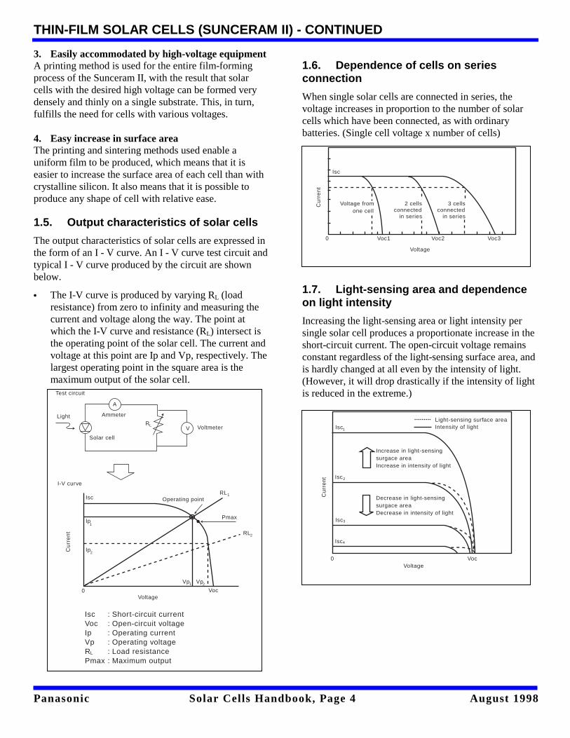
3. Easily accommodated by high-voltage equipment A printing method is used for the entire film-formingprocess of the Sunceram II, with the result that solarcells with the desired high voltage can be formed verydensely and thinly on a single substrate. This, in turn,fulfills the need for cells with various voltages. 4. Easy increase in surface area The printing and sintering methods used enable auniform film to be produced, which means that it iseasier to increase the surface area of each cell than withcrystalline silicon. It also means that it is possible toproduce any shape of cell with relative ease.
1.5. Output characteristics of solar cells
The output characteristics of solar cells are expressed inthe form of an I - V curve. An I - V curve test circuit andtypical I - V curve produced by the circuit are shownbelow. • The I-V curve is produced by varying RL (load
resistance) from zero to infinity and measuring thecurrent and voltage along the way. The point atwhich the I-V curve and resistance (RL) intersect isthe operating point of the solar cell. The current andvoltage at this point are Ip and Vp, respectively. Thelargest operating point in the square area is themaximum output of the solar cell.
1.6. Dependence of cells on seriesconnection
When single solar cells are connected in series, thevoltage increases in proportion to the number of solarcells which have been connected, as with ordinarybatteries. (Single cell voltage x number of cells)
1.7. Light-sensing area and dependenceon light intensity
Increasing the light-sensing area or light intensity persingle solar cell produces a proportionate increase in theshort-circuit current. The open-circuit voltage remainsconstant regardless of the light-sensing surface area, andis hardly changed at all even by the intensity of light.(However, it will drop drastically if the intensity of lightis reduced in the extreme.)
A
Test circuit
Light Ammeter
Solar cell
VRL Voltmeter
I-V curve
Operating pointIsc
Ip
Ip
1
2Cu
rre
nt
RL
Pmax
RL
Vp Vp2
2
1
1
VocVoltage
IscVocIpVpRPmax
: Short-circuit current: Open-circuit voltage: Operating current: Operating voltage: Load resistance: Maximum output
L
0
0 Voc1 Voc2 Voc3
Voltage from one cell
2 cellsconnected in series
3 cellsconnected in series
Cu
rre
nt
Isc
Voltage
Voltage
Cu
rre
nt
Light-sensing surface areaIntensity of light
Increase in light-sensingsurgace areaIncrease in intensity of light
Decrease in light-sensingsurgace areaDecrease in intensity of light
Isc
Isc
Isc
1
2
3
Isc4
0 Voc
Panasonic Solar Cells Handbook, Page 5 August 1998
THIN-FILM SOLAR CELLS (SUNCERAM II) – CONTINUED
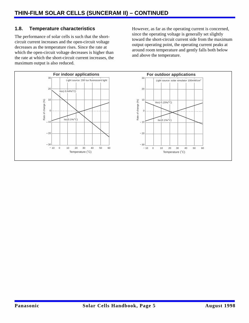
1.8. Temperature characteristics
The performance of solar cells is such that the short-circuit current increases and the open-circuit voltagedecreases as the temperature rises. Since the rate atwhich the open-circuit voltage decreases is higher thanthe rate at which the short-circuit current increases, themaximum output is also reduced.
However, as far as the operating current is concerned,since the operating voltage is generally set slightlytoward the short-circuit current side from the maximumoutput operating point, the operating current peaks ataround room temperature and gently falls both belowand above the temperature.
For indoor applications30
20
10
0
10
20
30
Rat
e of
cha
nge
(%)
10 0 10 20 30 40 50 60
Temperature (˚C)
Light source: 200 lux fluorescent light
Voc(-0.64%/˚C)
Isc(0.1%/˚C)
For outdoor applications30
20
10
0
10
20
30
Rat
e of
cha
nge
(%)
10 0 10 20 30 40 50 60
Temperature (˚C)
Light source: solar simulator 100mW/cm
Voc(-0.15%/˚C)
Isc(0.1%/˚C)
2
Panasonic Solar Cells Handbook, Page 6 August 1998
2. SUNCERAM II CELLS FOR INDOOR USE
2.1. General Information
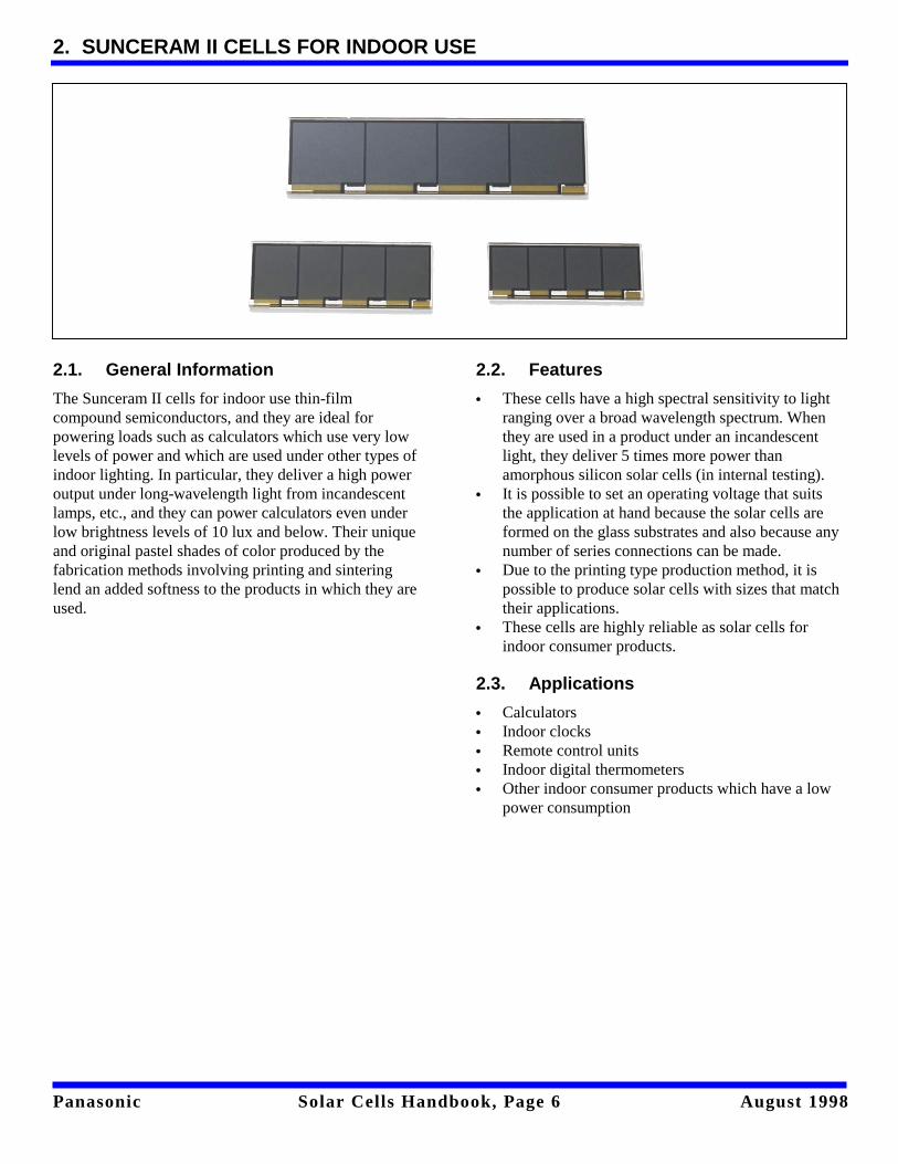
The Sunceram II cells for indoor use thin-filmcompound semiconductors, and they are ideal forpowering loads such as calculators which use very lowlevels of power and which are used under other types ofindoor lighting. In particular, they deliver a high poweroutput under long-wavelength light from incandescentlamps, etc., and they can power calculators even underlow brightness levels of 10 lux and below. Their uniqueand original pastel shades of color produced by thefabrication methods involving printing and sinteringlend an added softness to the products in which they areused.
2.2. Features
• These cells have a high spectral sensitivity to lightranging over a broad wavelength spectrum. Whenthey are used in a product under an incandescentlight, they deliver 5 times more power thanamorphous silicon solar cells (in internal testing).
• It is possible to set an operating voltage that suitsthe application at hand because the solar cells areformed on the glass substrates and also because anynumber of series connections can be made.
• Due to the printing type production method, it ispossible to produce solar cells with sizes that matchtheir applications.
• These cells are highly reliable as solar cells forindoor consumer products.
2.3. Applications
• Calculators• Indoor clocks• Remote control units• Indoor digital thermometers• Other indoor consumer products which have a low
power consumption
Panasonic Solar Cells Handbook, Page 7 August 1998
SUNCERAM II CELLS FOR INDOOR USE
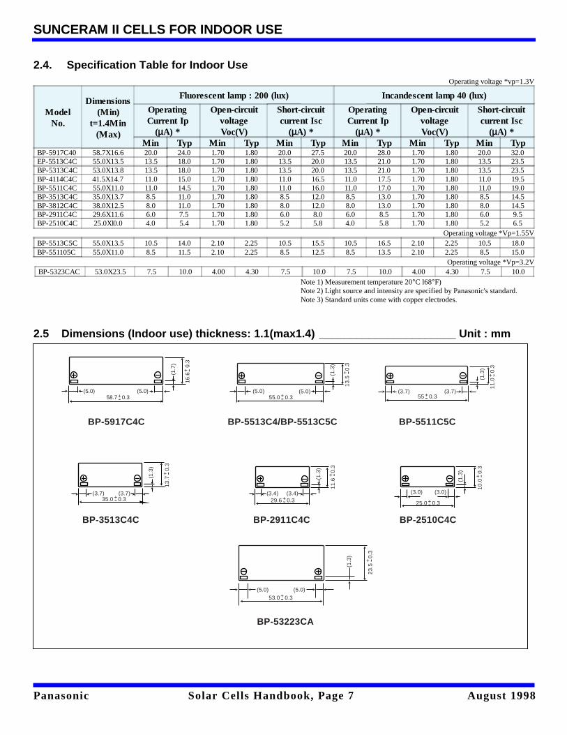
2.4. Specification Table for Indoor UseOperating voltage *vp=1.3V
ModelNo.
Dimensions(Min)
t=1.4Min(Max)
Fluorescent lamp : 200 (lux) Incandescent lamp 40 (lux)
OperatingCurrent Ip
(µA) *
Open-circuitvoltageVoc(V)
Short-circuitcurrent Isc
(µA) *
OperatingCurrent Ip
(µA) *
Open-circuitvoltageVoc(V)
Short-circuitcurrent Isc
(µA) *Min Typ Min Typ Min Typ Min Typ Min Typ Min Typ
BP-5917C40 58.7X16.6 20.0 24.0 1.70 1.80 20.0 27.5 20.0 28.0 1.70 1.80 20.0 32.0EP-5513C4C 55.0X13.5 13.5 18.0 1.70 1.80 13.5 20.0 13.5 21.0 1.70 1.80 13.5 23.5BP-5313C4C 53.0X13.8 13.5 18.0 1.70 1.80 13.5 20.0 13.5 21.0 1.70 1.80 13.5 23.5BP-4114C4C 41.5X14.7 11.0 15.0 1.70 1.80 11.0 16.5 11.0 17.5 1.70 1.80 11.0 19.5BP-5511C4C 55.0X11.0 11.0 14.5 1.70 1.80 11.0 16.0 11.0 17.0 1.70 1.80 11.0 19.0BP-3513C4C 35.0X13.7 8.5 11.0 1.70 1.80 8.5 12.0 8.5 13.0 1.70 1.80 8.5 14.5BP-3812C4C 38.0X12.5 8.0 11.0 1.70 1.80 8.0 12.0 8.0 13.0 1.70 1.80 8.0 14.5BP-2911C4C 29.6X11.6 6.0 7.5 1.70 1.80 6.0 8.0 6.0 8.5 1.70 1.80 6.0 9.5BP-2510C4C 25.0Xl0.0 4.0 5.4 1.70 1.80 5.2 5.8 4.0 5.8 1.70 1.80 5.2 6.5
Operating voltage *Vp=1.55VBP-5513C5C 55.0X13.5 10.5 14.0 2.10 2.25 10.5 15.5 10.5 16.5 2.10 2.25 10.5 18.0BP-551105C 55.0X11.0 8.5 11.5 2.10 2.25 8.5 12.5 8.5 13.5 2.10 2.25 8.5 15.0
Operating voltage *Vp=3.2VBP-5323CAC 53.0X23.5 7.5 10.0 4.00 4.30 7.5 10.0 7.5 10.0 4.00 4.30 7.5 10.0
Note 1) Measurement temperature 20°C l68°F)Note 2) Light source and intensity are specified by Panasonic's standard.Note 3) Standard units come with copper electrodes.
2.5 Dimensions (Indoor use) thickness: 1.1(max1.4) ______________________ Unit : mm
(5.0) (5.0)
(1.7
)
16.6
0.
3+ -
58.7 0.3+-
BP-5917C4C BP-5513C4/BP-5513C5C
(5.0) (5.0)55.0 0.3
(1.3
)
13.5
0
.3
(3.7)55 0.3
(3.7)
(1.3
)
11.0
0
.3(3.0) (3.0)
25.0 0.3
(1.3
)
10.0
0
.3
(3.4) (3.4)29.6 0.3
(3.7) (3.7)35.0 0.3
(1.3
)
13.7
0
.3
(5.0) (5.0)
53.0 0.3
(1.3
)
23.5
0
.3
(1.3
)
11.6
0
.3
BP-5511C5C
BP-2510C4CBP-2911C4CBP-3513C4C
BP-53223CA
+ -
+-
+ -
+-
+ -
+-
+ -
+-
+ -
+-
+ -
+-

Panasonic Solar Cells Handbook, Page 8 August 1998
SUNCERAM II CELLS FOR INDOOR USE - CONTINUED
2.6. Operating-Current vs. Operating-Voltage
BP-5917C4C
BP-2911C4C
BP-5511C5C
40
30
20
10
00 0.5 1.0 1.5 2.0 2.5
Voltage (V)
200 x
50 x
Flourescent lamp
Cu
rre
nt
(µA
)
Cu
rre
nt
(µA
)
40
30
20
10
00 0.5 1.0 1.5 2.0 2.5
40 x
10 x
Incandescent lamp
Voltage (V)
10
7.5
5
2.5
00 0.5 1.0 1.5 2.0 2.5
Voltage (V)
200 x
50 x
Flourescent lamp
Cu
rre
nt
(µA
)
Cu
rre
nt
(µA
)
0 0.5 1.0 1.5 2.0 2.5
40 x
10 x
Incandescent lamp
Voltage (V)
10
7.5
5
2.5
0
20
16
12
8
00 0.5 1.0 1.5 2.0 2.5 3.0
Voltage (V)
200 x
50 x
Flourescent lamp
Cu
rre
nt
(µA
)
Cu
rre
nt
(µA
)
40 x
10 x
Incandescent lamp
Voltage (V)
4
20
16
12
8
0
4
0 0.5 1.0 1.5 2.0 2.5 3.0
Panasonic Solar Cells Handbook, Page 9 August 1998
SUNCERAM II CELLS FOR INDOOR USE - CONTINUED
2.7. Precautions for use
[Adhere strictly to the guidelines below since mishandling the cells may impair their performance.]
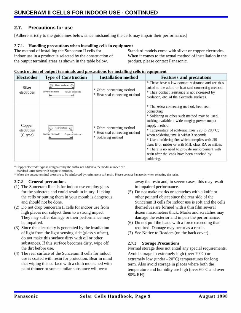
2.7.1. Handling precautions when installing cells in equipmentThe method of installing the Sunceram II cells forindoor use in a product is selected by the construction ofthe output terminal areas as shown in the table below.
Standard models come with silver or copper electrodes.When it comes to the actual method of installation in theproduct, please contact Panasonic.
Construction of output terminals and precautions for installing cells in equipmentElectrodes Type of Construction Installation method Features and precautions
Silverelectrodes
* Zebra connecting method* Heat seal connecting method
* These have a low contact resistance and are thussuited to the zebra or heat seal connecting method.* Their contact resistance is not increased byoxidation, etc. of the electrode surfaces.
Copperelectrodes(C type)
* Zebra connecting method* Heat seal connecting method* Soldering method
* The zebra connecting method, heat sealconnecting.* Soldering or other such method may be used,making available a wide-ranging power outputsupply method.* Temperature of soldering Iron: 220 to 280°C;when soldering time is within 3 seconds.* Use a soldering flux which complies with JISclass B or milder or with MIL class RA or milder.* There is no need to provide reinforcement withresin after the leads have been attached bysoldering.
* Copper electrode: type is designated by the suffix not added to the model number "C". Standard units come with copper electrodes.* When the output terminal areas are to be reinforced by resin, use a soft resin. Please contact Panasonic when selecting the resin.
2.7.2 General precautions(1) The Sunceram II cells for indoor use employ glass
for the substrate and could result in injury. Lickingthe cells or putting them in your mouth is dangerousand should not be done.
(2) Do not drop Sunceram II cells for indoor use fromhigh places nor subject them to a strong impact.They may suffer damage or their performance maybe impaired.
(3) Since the electricity is generated by the irradiationof light from the light-sensing side (glass surface),do not make this surface dirty with oil or othersubstances. If this surface becomes dirty, wipe offthe dirt before use.
(4) The rear surface of the Sunceram II cells for indooruse is coated with resin for protection. Bear in mindthat wiping this surface with a cloth moistened withpaint thinner or some similar substance will wear
away the resin and, in severe cases, this may resultin impaired performance.
(5) Do not make marks or scratches with a knife orother pointed object since the rear side of theSunceram II cells for indoor use is soft and the cellsthemselves are formed with a thin film severaldozen micrometers thick. Marks and scratches maydamage the exterior and impair the performance.
(6) Do not pull the leads with a force exceeding thatrequired. Damage may occur as a result.
(7) See Notice to Readers (on the back cover).
2.7.3 Storage PrecautionsNormal storage does not entail any special requirements.Avoid storage in extremely high (over 70°C) orextremely low (under - 20°C) temperatures for longterm. Also avoid storage in places where both thetemperature and humidity are high (over 60°C and over80% RH).
Silver electrode Silver electrode
Rear surface
Copper electrode Copper electrode
Rear surface
Panasonic Solar Cells Handbook, Page 10 August 1998
3. SUNCERAM II CELL FOR OUTDOOR USE
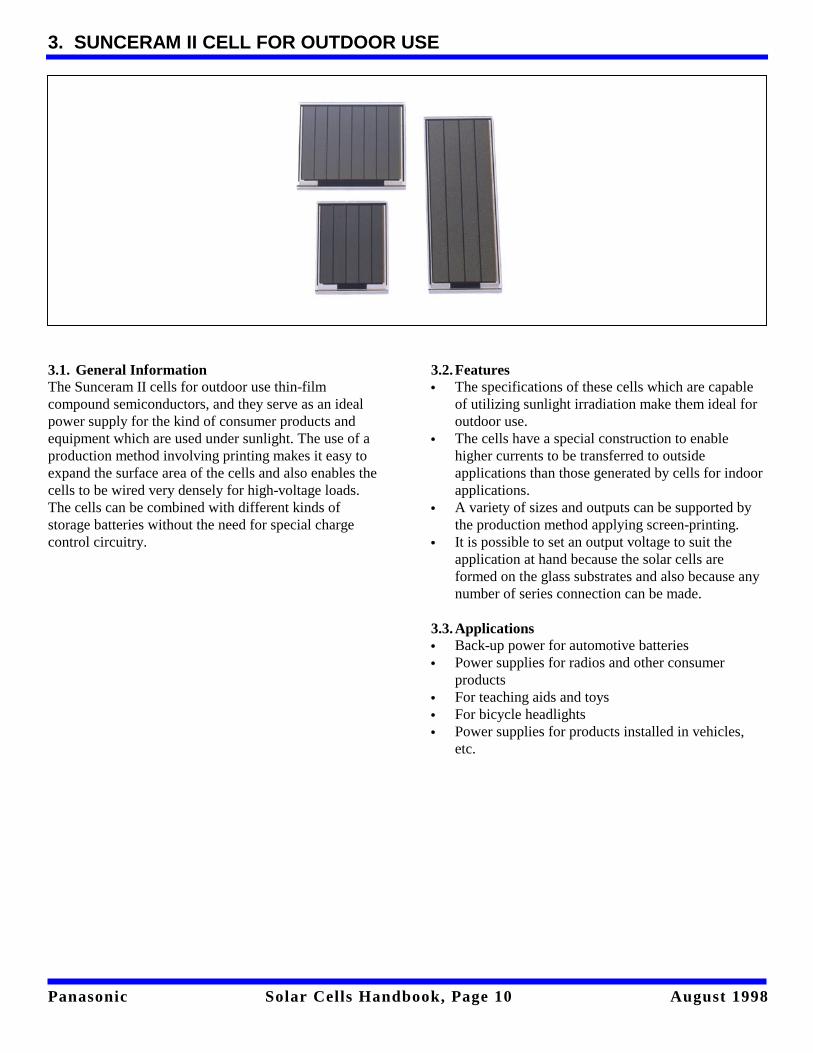
3.1. General InformationThe Sunceram II cells for outdoor use thin-filmcompound semiconductors, and they serve as an idealpower supply for the kind of consumer products andequipment which are used under sunlight. The use of aproduction method involving printing makes it easy toexpand the surface area of the cells and also enables thecells to be wired very densely for high-voltage loads.The cells can be combined with different kinds ofstorage batteries without the need for special chargecontrol circuitry.
3.2. Features• The specifications of these cells which are capable
of utilizing sunlight irradiation make them ideal foroutdoor use.
• The cells have a special construction to enablehigher currents to be transferred to outsideapplications than those generated by cells for indoorapplications.
• A variety of sizes and outputs can be supported bythe production method applying screen-printing.
• It is possible to set an output voltage to suit theapplication at hand because the solar cells areformed on the glass substrates and also because anynumber of series connection can be made.
3.3. Applications• Back-up power for automotive batteries• Power supplies for radios and other consumer
products• For teaching aids and toys• For bicycle headlights• Power supplies for products installed in vehicles,
etc.

Panasonic Solar Cells Handbook, Page 11 August 1998
SUNCERAM II CELL FOR OUTDOOR USE - CONTINUED
3.4.Specification Table for Outdoor Use
Model No.Dimensions (mm)t =1.4mm (Max.)
light source AM=1.5 : 100mW/cm
Operatingvoltage Vp
(V)
Operating current Ip(mA)
Open-circuit voltageVoc (V)
Short-circuit currentIsc (mA)
Average Average AverageBR-243318C 24.0X33.0
1.816.4 3.45 17.5
BR-246618C 24.0X66.0 35.0 2.80 39.0BR-242221C 24.0X22.0 2.1 6.6 4.15 7.0BP-372234C 37.0X22.0
3.4
8.5 5.50 9.0BP-373334C 37.0X33.0 14.5 5.50 15.5BP-376634C 37.0X66.0 31.5 5.50 33.0BR-378234C 37.0X82.0 40.0 5.50 43.0BR-160334C 165.0X27.0 650 5.50 71.5BR-748264C 74.0X82.0 6.4 40.0 11.0 43.0BR-111108C 110.0X110.0 8.0 76.0 12.0 84.0BR-160416C 162.5X41.0
16.019.1 24.0 20.5
BP-160516C 162.5X48.0 22.1 24.0 23.5BR-160716C 162.5X73.0 34.0 24.0 36.0
Note 1) Measurement temperature 25°C (77°F)Note 2) Light source and intensity are specified by Panasonic’s standard.Note 3) Standard units come with copper electrodes.
3.5.Dimensions (Outdoor use) thickness: 1.1(maxl.4) ___________________________________ Unit: mm
(1.4)(6
.0)
16.6
0.
3+ -
162.5 0.3+-
BP-160716C
(1.4)(6.0)
37.0 0.3
(1.6
) 66.0
0.
3
(6.0)
+-
+ -
BP-376634C

Panasonic Solar Cells Handbook, Page 12 August 1998
SUNCERAM II CELL FOR OUTDOOR USE - CONTINUED
3.6. Operating-Current vs. Operating-Voltage
100mW/cm²
75mW/cm²
50mW/cm²
25mW/cm²
100mW/cm²
75mW/cm²
50mW/cm²
25mW/cm²
50
40
30
20
10
0
50
40
30
20
10
0
Cur
rent
(m
A)
50
40
30
20
10
0
Cur
rent
(m
A)
50
40
30
20
10
0
100mW/cm²
75mW/cm²
50mW/cm²
25mW/cm²
Cur
rent
(m
A)
Voltage (V)
0 1 2 3 4 5
AM1.5BP-246618C BP-242221C
AM1.5
Voltage (V)
0 1 2 3 4 5
100mW/cm²
75mW/cm²
50mW/cm²
25mW/cm²
100mW/cm²
75mW/cm²
50mW/cm²
25mW/cm²
Cur
rent
(m
A)
Voltage (V)
0 2 4 6 8 10
AM1.5BP-373334C BP-376634C
AM1.5
Voltage (V)
100mW/cm²
75mW/cm²
50mW/cm²
25mW/cm²
0 2 4 6 8 10
50
40
30
20
10
0
Cur
rent
(m
A)
50
40
30
20
10
0
Cur
rent
(m
A)
Voltage (V)
0 3 6 9 12 15
AM1.5BP-748264C BP-160716C
AM1.5
Voltage (V)
0 6 12 18 24 30

Panasonic Solar Cells Handbook, Page 13 August 1998
SUNCERAM II CELL FOR OUTDOOR USE - CONTINUED
3.7. Precautions for use
[Adhere strictly to the guidelines below sincemishandling the cells may impair their performance.]
3.7.1. Handling precautions for installationIt should be borne in mind that the Sunceram II cells foroutdoor use applications are energized by sunlight andnot by fluorescent or incandescent lights. Forapplications such as back-up power for car batteries, invehicle-mounted products such as ventilator fans, radar
detectors and deodorizers, and in teaching aids and toys,these cells are designed to be suitable for uses which donot involve direct and/or continuous exposure to rainand wind. This not withstanding, they are used in all-outdoor environments, (eg: garden lights, bicycleheadlights, outdoor clocks powered by solar cells, andwork indicator lights). If the cells are to be employed insuch ways, the following handling precautions must bestrictly adhered to.See Notice to Readers (on the back cover).
3.7.2. Handling precautions when installing cells in appliances1. Connecting the leadsThe table below shows the output terminal choicesavailable for the electrodes of the Sunceram II cells for
outdoor applications. (The standard units have copperelectrodes.)
Construction of output terminals and precautions for installing cells in equipmentElectrodes Type of Construction Features and precautions
Copper electrodes(C type)
* Temperature of the soldering iron tip 220 to 280°C* Completion of soldering within 3 seconds.* Soldering flux: Must comply with JIS class B or milder or withMIL class RA or milder.
Pre-Soldered electrodes(S type)
* Temperature of the soldering iron tip 220 to 260°C* Completion of soldering within 3 seconds.* Soldering flux Must comply with JIS class B or milder or withMIL class RA or milder.
With lead wire(L type) * Do not pull the leads beyond what is required.
* Copper electrodes type is designated by the suffix not added to the model number “C". Standard units come with copper electrodes.* When the output terminal areas are to be reinforced by resin use a soft resin. Please contact Panasonic when selecting the resin.
2. Installing Sunceram II cells for outdoor use inappliancesImproper installation of Sunceram II cells for outdooruse in appliance may impair proper functioning of theunits.• Protecting Sunceram II cells for outdoor use with a
transparent coverProtect Sunceram II cells for outdoor use from theelement with a transparent cover. Weatherproofmaterials such as acrylic resin and polycarbonate arerecommended for this purpose. As shown in thefigure below, ideally, the shield should completelycover Sunceram II cells for outdoor use.
Mounting Sunceram II(1) To mount Sunceram II cells for outdoor use to
appliances, use a flexible means of a attachmentwhich will not accumulate heat, such as double-sided adhesive tape.
(2) In mounting Sunceram II cells for outdoor use, donot press down on the unit from above. If pressure isabsolutely necessary, press on the edge of SunceramII cells for outdoor use without compressing theentire unit and use a soft material to grasp it.
(3) In mounting Sunceram II cells for outdoor use ontoappliances, allow some space between theappliances and Sunceram II cells as shown in thepicture below. If no space is left, Sunceram II cellsfor outdoor use may break through expansion andcontraction caused by heat. Use heat and weather-proof materials for installation.
Cross--sectional view
transparent cover
Fastening parts
Sunceram II cells for outdoor use
Copper electrode Copper electrode
Rear surface
solder electrode solder electrode
Rear surface
Rear surface
SolderelectrodeLead wire
Panasonic Solar Cells Handbook, Page 14 August 1998
SUNCERAM II CELL FOR OUTDOOR USE - CONTINUED
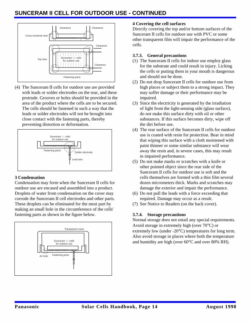
(4) The Sunceram II cells for outdoor use are provided
with leads or solder electrodes on the rear, and theseprotrude. Grooves or holes should be provided in thearea of the product where the cells are to be secured.The cells should be fastened in such a way that theleads or solder electrodes will not be brought intoclose contact with the fastening parts, therebypreventing distortion or deformation.
3 CondensationCondensation may form when the Sunceram II cells foroutdoor use are encased and assembled into a product.Droplets of water from condensation on the cover maycorrode the Sunceram II cell electrodes and other parts.These droplets can be eliminated for the most part bymaking an small hole in the circumference of the cells'fastening parts as shown in the figure below.
4 Covering the cell surfacesDirectly covering the top and/or bottom surfaces of theSunceram II cells for outdoor use with PVC or someother transparent film will impair the performance of thecells.
3.7.3. General precautions(1) The Sunceram II cells for indoor use employ glass
for the substrate and could result in injury. Lickingthe cells or putting them in your mouth is dangerousand should not be done.
(2) Do not drop Sunceram II cells for outdoor use fromhigh places or subject them to a strong impact. Theymay suffer damage or their performance may beimpaired.
(3) Since the electricity is generated by the irradiationof light from the light-sensing side (glass surface),do not make this surface dirty with oil or othersubstances. If this surface becomes dirty, wipe offthe dirt before use.
(4) The rear surface of the Sunceram II cells for outdooruse is coated with resin for protection. Bear in mindthat wiping this surface with a cloth moistened withpaint thinner or some similar substance will wearaway the resin and, in severe cases, this may resultin impaired performance.
(5) Do not make marks or scratches with a knife orother pointed object since the rear side of theSunceram II cells for outdoor use is soft and thecells themselves are formed with a thin film severaldozen micrometers thick. Marks and scratches maydamage the exterior and impair the performance.
(6) Do not pull the leads with a force exceeding thatrequired. Damage may occur as a result.
(7) See Notice to Readers (on the back cover).
3.7.4. Storage precautionsNormal storage does not entail any special requirements.Avoid storage in extremely high (over 70°C) orextremely low (under -20°C) temperatures for long term.Also avoid storage in places where both the temperatureand humidity are high (over 60°C and over 80% RH).
Sunceram II cells for outdoor use
Top view
Cross-sectional view
Fastening parts
Clearance
Clearance
Clearance
Clearance
Fastening parts
Sunceram II cells for outdoor use
Solder electrode
Lead wire
Transparent cover
Fastening partsAir hole
Sunceram II cells for outdoor use
Panasonic Solar Cells Handbook, Page 15 August 1998
4. SUNCERAM II MODULES FOR OUTDOOR USE
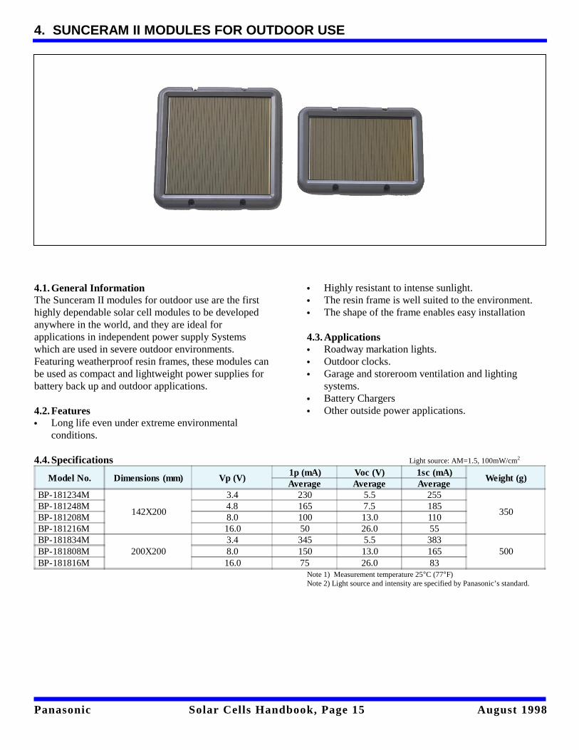
4.1.General InformationThe Sunceram II modules for outdoor use are the firsthighly dependable solar cell modules to be developedanywhere in the world, and they are ideal forapplications in independent power supply Systemswhich are used in severe outdoor environments.Featuring weatherproof resin frames, these modules canbe used as compact and lightweight power supplies forbattery back up and outdoor applications.
4.2.Features• Long life even under extreme environmental
conditions.
• Highly resistant to intense sunlight.• The resin frame is well suited to the environment.• The shape of the frame enables easy installation
4.3.Applications• Roadway markation lights.• Outdoor clocks.• Garage and storeroom ventilation and lighting
systems.• Battery Chargers• Other outside power applications.
4.4.Specifications Light source: AM=1.5, 100mW/cm2
Model No. Dimensions (mm) Vp (V)1p (mA) Voc (V) 1sc (mA)
Weight (g)Average Average Average
BP-181234M
142X200
3.4 230 5.5 255
350BP-181248M 4.8 165 7.5 185BP-181208M 8.0 100 13.0 110BP-181216M 16.0 50 26.0 55BP-181834M
200X2003.4 345 5.5 383
500BP-181808M 8.0 150 13.0 165BP-181816M 16.0 75 26.0 83
Note 1) Measurement temperature 25°C (77°F)Note 2) Light source and intensity are specified by Panasonic’s standard.
Panasonic Solar Cells Handbook, Page 16 August 1998
SUNCERAM II MODULES FOR OUTDOOR USE - CONTINUED
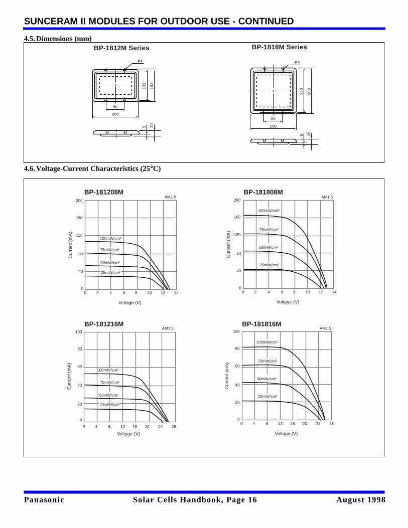
4.5.Dimensions (mm)
4.6.Voltage-Current Characteristics (25°C)
BP-1818M SeriesBP-1812M Series
4
132
142
80
20080
200
190
200
4
5 20
5 20
100mW/cm²
75mW/cm²
50mW/cm²
25mW/cm²
0 4 8 12 16 20 24 28
Voltage (V)
100
80
60
40
20
0
Cur
rent
(m
A)
BP-181816MAM1.5
100mW/cm²
75mW/cm²
50mW/cm²
25mW/cm²
0 4 8 12 16 20 24 28
Voltage (V)
100
80
60
40
20
0
Cur
rent
(m
A)
BP-181216MAM1.5
100mW/cm²
75mW/cm²
50mW/cm²
25mW/cm²
0 2 4 6 8 10 12 14
Voltage (V)
200
160
120
80
40
0
Cur
rent
(m
A)
100mW/cm²
75mW/cm²
50mW/cm²
25mW/cm²
0 2 4 6 8 10 12 14
Voltage (V)
200
160
120
80
40
0
Cur
rent
(m
A)
BP-181808MBP-181208MAM1.5 AM1.5
Panasonic Solar Cells Handbook, Page 17 August 1998
SUNCERAM II MODULES FOR OUTDOOR USE - CONTINUED
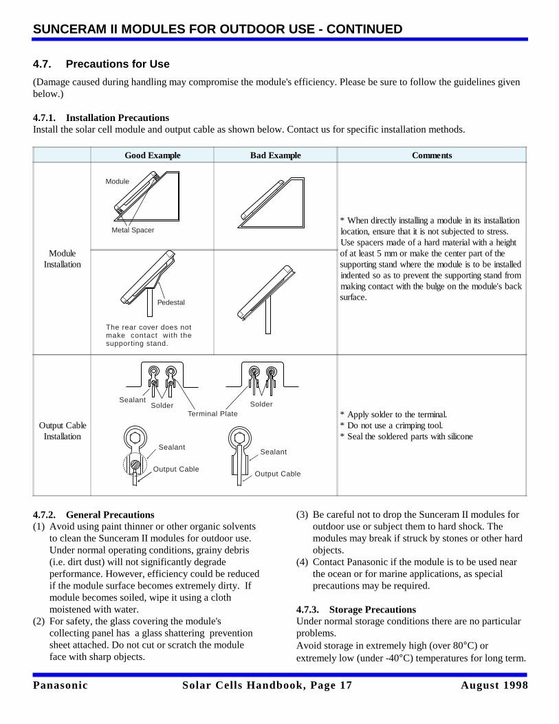
4.7. Precautions for Use
(Damage caused during handling may compromise the module's efficiency. Please be sure to follow the guidelines givenbelow.)
4.7.1. Installation PrecautionsInstall the solar cell module and output cable as shown below. Contact us for specific installation methods.
Good Example Bad Example Comments
ModuleInstallation
* When directly installing a module in its installationlocation, ensure that it is not subjected to stress.Use spacers made of a hard material with a heightof at least 5 mm or make the center part of thesupporting stand where the module is to be installedindented so as to prevent the supporting stand frommaking contact with the bulge on the module's backsurface.
Output CableInstallation
* Apply solder to the terminal.* Do not use a crimping tool.* Seal the soldered parts with silicone
4.7.2. General Precautions(1) Avoid using paint thinner or other organic solvents
to clean the Sunceram II modules for outdoor use.Under normal operating conditions, grainy debris(i.e. dirt dust) will not significantly degradeperformance. However, efficiency could be reducedif the module surface becomes extremely dirty. Ifmodule becomes soiled, wipe it using a clothmoistened with water.
(2) For safety, the glass covering the module'scollecting panel has a glass shattering preventionsheet attached. Do not cut or scratch the moduleface with sharp objects.
(3) Be careful not to drop the Sunceram II modules foroutdoor use or subject them to hard shock. Themodules may break if struck by stones or other hardobjects.
(4) Contact Panasonic if the module is to be used nearthe ocean or for marine applications, as specialprecautions may be required.
4.7.3. Storage PrecautionsUnder normal storage conditions there are no particularproblems.Avoid storage in extremely high (over 80°C) orextremely low (under -40°C) temperatures for long term.
Module
Metal Spacer
Pedestal
The rear cover does notmake contact with thesupporting stand.
SolderSealant
Terminal PlateSolder
Sealant
Output Cable
Sealant
Output Cable
Panasonic Solar Cells Handbook, Page 18 August 1998
5. THIN FILM SOLAR CELL SUNCERAM II OUTDOOR SOLAR POWER SUPPLY
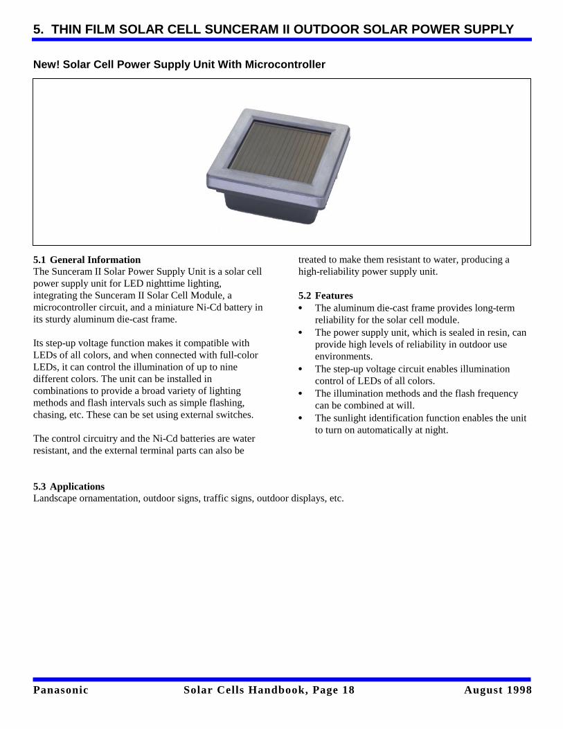
New! Solar Cell Power Supply Unit With Microcontroller
5.1 General InformationThe Sunceram II Solar Power Supply Unit is a solar cellpower supply unit for LED nighttime lighting,integrating the Sunceram II Solar Cell Module, amicrocontroller circuit, and a miniature Ni-Cd battery inits sturdy aluminum die-cast frame.
Its step-up voltage function makes it compatible withLEDs of all colors, and when connected with full-colorLEDs, it can control the illumination of up to ninedifferent colors. The unit can be installed incombinations to provide a broad variety of lightingmethods and flash intervals such as simple flashing,chasing, etc. These can be set using external switches.
The control circuitry and the Ni-Cd batteries are waterresistant, and the external terminal parts can also be
treated to make them resistant to water, producing ahigh-reliability power supply unit.
5.2 Features• The aluminum die-cast frame provides long-term
reliability for the solar cell module.• The power supply unit, which is sealed in resin, can
provide high levels of reliability in outdoor useenvironments.
• The step-up voltage circuit enables illuminationcontrol of LEDs of all colors.
• The illumination methods and the flash frequencycan be combined at will.
• The sunlight identification function enables the unitto turn on automatically at night.
5.3 ApplicationsLandscape ornamentation, outdoor signs, traffic signs, outdoor displays, etc.
Panasonic Solar Cells Handbook, Page 19 August 1998
THIN FILM SOLAR CELL SUNCERAM II OUTDOOR SOLAR POWER SUPPLY UNIT
• Standard SpecificationsSolar cell output: 3.4 V 80 mA (AM 1.5, 100 mW/cm2)Ni-Cd battery rating: 2.4 V 500 mAh (5 hour ratio)No. of outputs (maximum number of LED line connectors)
For monochrome LED use: 6 lines (2 lines per terminal)For full-color LED use: 3 lines (2 lines per terminal)
Illumination Method:For monochrome LED use: Continuous illumination, flashing, chasing, alternating, fluorescent flashingFor full-color LED use: Continuous, flashing, multi-color chasingFlash Interval: 0.1 sec., 0.5 sec., 1.0 sec., 2.0 sec. (the fluorescent light flash interval is fixed at
3.0 sec.)Duty cycle:
Flashing, chasing, alternating,and multi-color chasing: Approx. 5%Fluorescent flashing: Approx. 15%
LED Operating Current:Flashing, chasing, alternating: max 40 mA/chMulticolor chasing: max 40 mA/chFluorescent flashing: max 20 mA/chContinuous illumination: max 3 mA/ch
Control Method: External switchSunlight Identification Level: 20 to 200 Lx
• Guidelines for the Useable Consumption CurrentRegion and Time of Use Daily Sunlight (average installation) Useable Consumption Current
Winter in the cold regions of Japan 1.2 kWh/m2 80 mAh/dayWinter in the Pacific Ocean side of Japan 2.0 kWh/m2 130 mAh/day
Japanese average throughout the year 3.5 kWh/m2 240 mAh/dayJapan in the summer. 4.5 kWh/m2 310 mAh/day
* This assumes 85% charge and discharge efficiency.
(Notes and Cautions Regarding Use)(1) When the photoreceptor side of the solar cell isinstalled at an angle of 45° facing south, the useableelectricity in the average installation in the winter timewill increase by a factor of approximately 1.5 relative toa horizontal installation; however, the power in thesummer time will fall approximately 15%.(2) Be aware that the amount of electricity producedmay suffer due to the proximity of trees and buildings.
(3) Be aware that the night light may not turn on if theunit is exposed to strong external lights such as streetlights.(4) If the units are stored for an extended period of time,use the unit only after fully charging in direct sunlight.(5) See the user specifications for other details andcautions.
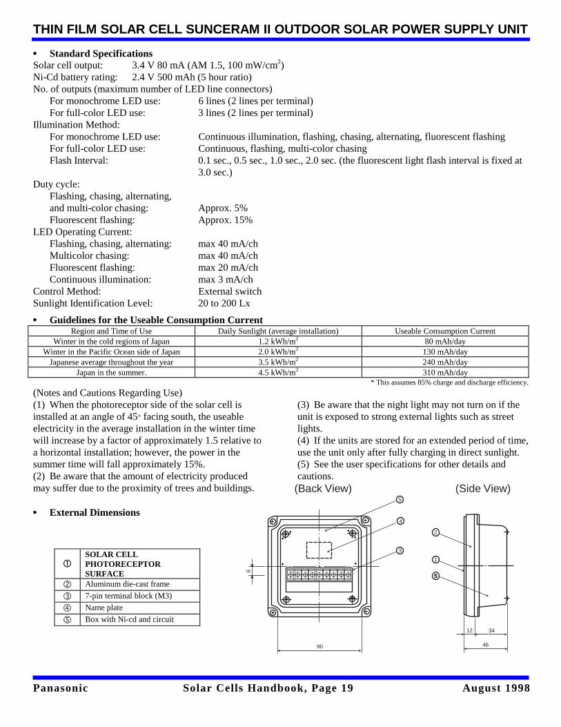
• External Dimensions
ccSOLAR CELLPHOTORECEPTORSURFACE
d Aluminum die-cast frame
e 7-pin terminal block (M3)
f Name plate
g Box with Ni-cd and circuit
2
1
5
12 34
46
3
4
5
90
6
(Side View)(Back View)
Panasonic Solar Cells Handbook, Page 20 August 1998
6. SUNCERAM II POWER UNITS FOR OUTDOOR USE
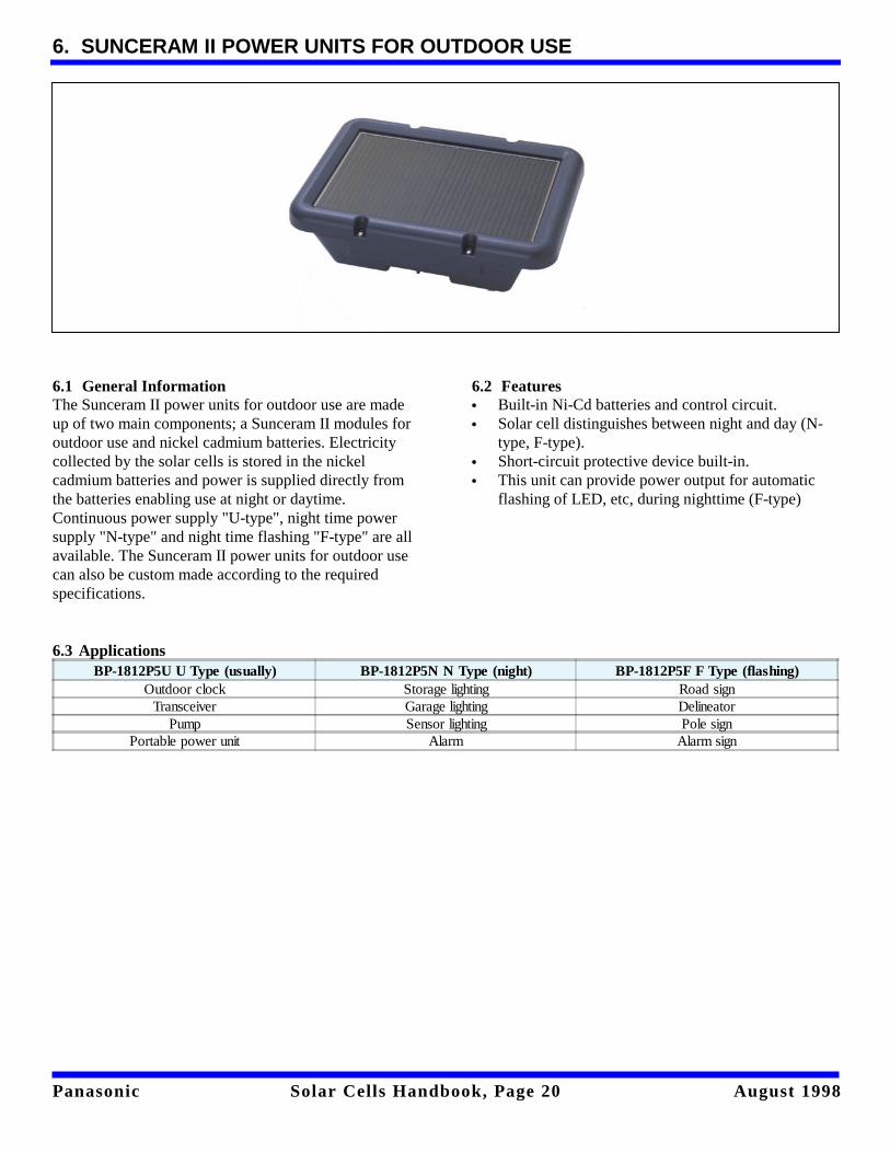
6.1 General InformationThe Sunceram II power units for outdoor use are madeup of two main components; a Sunceram II modules foroutdoor use and nickel cadmium batteries. Electricitycollected by the solar cells is stored in the nickelcadmium batteries and power is supplied directly fromthe batteries enabling use at night or daytime.Continuous power supply "U-type", night time powersupply "N-type" and night time flashing "F-type" are allavailable. The Sunceram II power units for outdoor usecan also be custom made according to the requiredspecifications.
6.2 Features• Built-in Ni-Cd batteries and control circuit.• Solar cell distinguishes between night and day (N-
type, F-type).• Short-circuit protective device built-in.• This unit can provide power output for automatic
flashing of LED, etc, during nighttime (F-type)
6.3 ApplicationsBP-1812P5U U Type (usually) BP-1812P5N N Type (night) BP-1812P5F F Type (flashing)
Outdoor clock Storage lighting Road signTransceiver Garage lighting Delineator
Pump Sensor lighting Pole signPortable power unit Alarm Alarm sign
Panasonic Solar Cells Handbook, Page 21 August 1998
SUNCERAM II POWER UNITS FOR OUTDOOR USE - CONTINUED
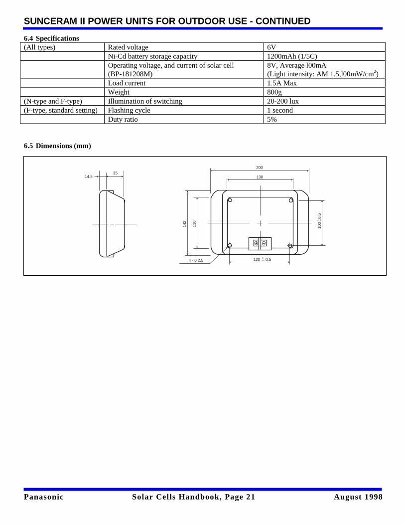
6.4 Specifications(All types) Rated voltage 6V
Ni-Cd battery storage capacity 1200mAh (1/5C)Operating voltage, and current of solar cell(BP-181208M)
8V, Average l00mA(Light intensity: AM 1.5,l00mW/cm2)
Load current 1.5A MaxWeight 800g
(N-type and F-type) Illumination of switching 20-200 lux(F-type, standard setting) Flashing cycle 1 second
Duty ratio 5%
6.5 Dimensions (mm)
200
130
120 0.5+-
100
0.5
+ -
4 - 0 2.5
142
110
14.535
Panasonic Solar Cells Handbook, Page 22 August 1998
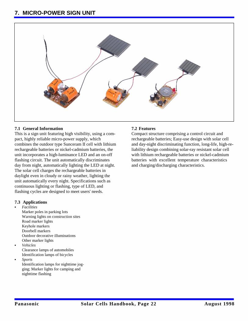
7. MICRO-POWER SIGN UNIT
7.1 General InformationThis is a sign unit featuring high visibility, using a com-pact, highly reliable micro-power supply, whichcombines the outdoor type Sunceram II cell with lithiumrechargeable batteries or nickel-cadmium batteries, theunit incorporates a high-luminance LED and an on-offflashing circuit. The unit automatically discriminatesday from night, automatically lighting the LED at night.The solar cell charges the rechargeable batteries indaylight even in cloudy or rainy weather, lighting theunit automatically every night. Specifications such ascontinuous lighting or flashing, type of LED, andflashing cycles are designed to meet users' needs.
7.2 FeaturesCompact structure comprising a control circuit andrechargeable batteries; Easy-use design with solar celland day-night discriminating function, long-life, high-re-liability design combining solar-ray resistant solar cellwith lithium rechargeable batteries or nickel-cadmiumbatteries with excellent temperature characteristicsand charging/discharging characteristics.
7.3 Applications• Facilities
Marker poles in parking lots Warning lights on construction sites Road marker lights Keyhole markers Doorbell markers Outdoor decorative illuminations Other marker lights
• Vehicles Clearance lamps of automobilesIdentification lamps of bicycles
• SportsIdentification lamps for nighttime jog-ging; Marker lights for camping andnighttime flashing
Panasonic Solar Cells Handbook, Page 23 August 1998
MICRO-POWER SIGN UNIT - CONTINUED
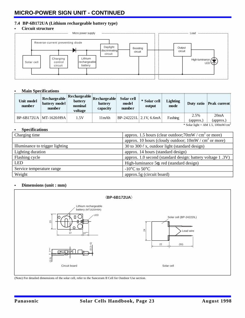
7.4 BP-6B172UA (Lithium rechargeable battery type)• Circuit structure • Main Specifications
Unit modelnumber
Rechargeablebattery model
number
Rechargeablebatterynominalvoltage
Rechargeablebatterycapacity
Solar cellmodel
number
* Solar celloutput
Lightingmode
Duty ratio Peak current
BP-6B172UA MT-1620/H9A 1.5V 11mAh BP-242221L 2.1V, 6.6mA Fashing2.5%
(approx.)20mA
(approx.) * Solar light = AM 1.5, 100mW/cm2
• Specifications Charging time approx. 1.5 hours (clear outdoor;70mW / cm2 or more) approx. 10 hours (cloudy outdoor; 10mW / cm2 or more) Illuminance to trigger lighting 30 to 300" x, outdoor light (standard design) Lighting duration approx. 14 hours (standard design) Flashing cycle approx. 1.0 second (standard design: battery voltage 1 .3V) LED High-luminance 5φ, red (standard design) Service temperature range -10°C to 50°C Weight approx.5g (circuit board) • Dimensions (unit : mm)
(Note) For detailed dimensions of the solar cell, refer to the Sunceram II Cell for Outdoor Use section.
Reverse-current preventing diode
Solar cellCharging control circuit
Lithiumrechargeable battery
Daylightdiscriminating circuit
Boosting circuit
Output circuit
High-luminance LED
Micro power supply Load
BP-6B172UA
Lithium rechargeablebattery (MT1620/H9A)
LED
1037
23
MAX
Circuit board
(2.5
)7
MA
X
(0.3
1)
Lead wire
(50)22
24
Solar cell (BP-24222IL)
Solar cell
Panasonic Solar Cells Handbook, Page 24 August 1998
MICRO-POWER SIGN UNIT - CONTINUED
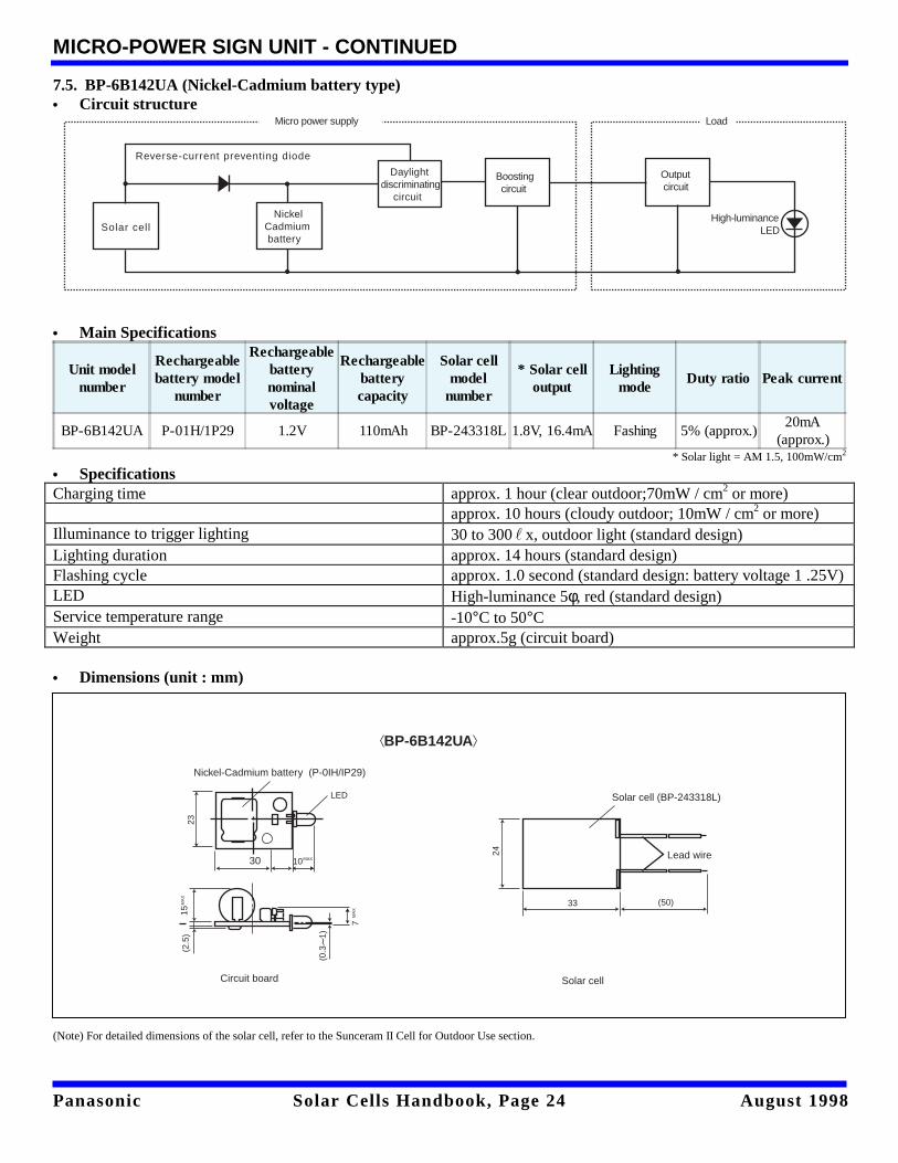
7.5. BP-6B142UA (Nickel-Cadmium battery type)• Circuit structure • Main Specifications
Unit modelnumber
Rechargeablebattery model
number
Rechargeablebatterynominalvoltage
Rechargeablebatterycapacity
Solar cellmodel
number
* Solar celloutput
Lightingmode
Duty ratio Peak current
BP-6B142UA P-01H/1P29 1.2V 110mAh BP-243318L 1.8V, 16.4mA Fashing 5% (approx.)20mA
(approx.) * Solar light = AM 1.5, 100mW/cm2
• Specifications Charging time approx. 1 hour (clear outdoor;70mW / cm2 or more) approx. 10 hours (cloudy outdoor; 10mW / cm2 or more) Illuminance to trigger lighting 30 to 300" x, outdoor light (standard design) Lighting duration approx. 14 hours (standard design) Flashing cycle approx. 1.0 second (standard design: battery voltage 1 .25V) LED High-luminance 5φ, red (standard design) Service temperature range -10°C to 50°C Weight approx.5g (circuit board) • Dimensions (unit : mm)
(Note) For detailed dimensions of the solar cell, refer to the Sunceram II Cell for Outdoor Use section.
Reverse-current preventing diode
Solar cell Nickel Cadmium battery
Daylightdiscriminating circuit
Boosting circuit
Output circuit
High-luminance LED
Micro power supply Load
BP-6B142UA
LED
10
23
MAX
Circuit board
(2.5
)15
MA
X
(0.3
1)
Lead wire
(50)
24
Solar cell (BP-243318L)
Solar cell
33
30
Nickel-Cadmium battery (P-0IH/IP29)
7M
AX
Panasonic Solar Cells Handbook, Page 25 August 1998
MICRO-POWER SIGN UNIT - CONTINUED
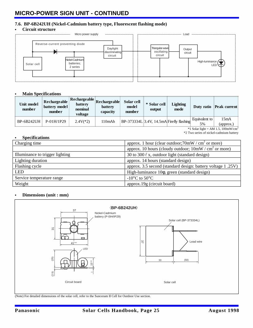
7.6. BP-6B242UH (Nickel-Cadmium battery type, Fluorescent flashing mode)• Circuit structure • Main Specifications
Unit modelnumber
Rechargeablebattery model
number
Rechargeablebatterynominalvoltage
Rechargeablebatterycapacity
Solar cellmodel
number
* Solar celloutput
Lightingmode
Duty ratio Peak current
BP-6B242UH P-01H/1P29 2.4V(*2) 110mAh BP-373334L 3.4V, 14.5mA Firefly flashingEquivalent to
5%15mA
(approx.) *1 Solar light = AM 1.5, 100mW/cm2
*2 Two series of nickel-cadmium battery
• Specifications Charging time approx. 1 hour (clear outdoor;70mW / cm2 or more) approx. 10 hours (cloudy outdoor; 10mW / cm2 or more) Illuminance to trigger lighting 30 to 300" x, outdoor light (standard design) Lighting duration approx. 14 hours (standard design) Flashing cycle approx. 3.5 second (standard design: battery voltage 1 .25V) LED High-luminance 10φ, green (standard design) Service temperature range -10°C to 50°C Weight approx.19g (circuit board) • Dimensions (unit : mm)
(Note) For detailed dimensions of the solar cell, refer to the Sunceram II Cell for Outdoor Use section.
Reverse-current preventing diode
Solar cell
Daylightdiscriminating circuit
Output circuit
High-luminance LED
Micro power supply Load
Triangular-wave oscillating circuit
Nickel-Cadmium batteries; 2 series
BP-6B242UH
Circuit board
(2.5
)
Lead wire
(50)
Solar cell (BP-373334L)
Solar cell
33
15M
AX
37
37
31
41MAX
Nickel-Cadmiumbattery (P-0IH/IP29)
(25)
LED
Panasonic Solar Cells Handbook, Page 26 August 1998
8. SOLAR CELL-POWERED WARNING LIGHTS
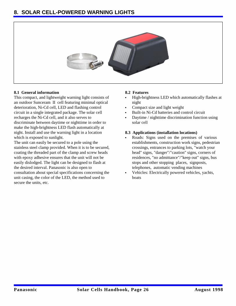
8.1 General informationThis compact, and lightweight warning light consists ofan outdoor Sunceram II cell featuring minimal opticaldeterioration, Ni-Cd cell, LED and flashing controlcircuit in a single integrated package. The solar cellrecharges the Ni-Cd cell, and it also serves todiscriminate between daytime or nighttime in order tomake the high-brightness LED flash automatically atnight. Install and use the warning light in a locationwhich is exposed to sunlight.The unit can easily be secured to a pole using thestainless steel clamp provided. When it is to be secured,coating the threaded part of the clamp and screw headswith epoxy adhesive ensures that the unit will not beeasily dislodged. The light can be designed to flash atthe desired interval. Panasonic is also open toconsultation about special specifications concerning theunit casing, the color of the LED, the method used tosecure the units, etc.
8.2 Features• High-brightness LED which automatically flashes at
night• Compact size and light weight• Built-in Ni-Cd batteries and control circuit• Daytime / nighttime discrimination function using
solar cell
8.3 Applications (installation locations)• Roads: Signs used on the premises of various
establishments, construction work signs, pedestriancrossings, entrances to parking lots, "watch yourhead" signs, "danger"/"caution" signs, corners ofresidences, "no admittance"/"keep out" signs, busstops and other stopping places, signposts,telephones, automatic vending machines
• Vehicles: Electrically powered vehicles, yachts,boats
Panasonic Solar Cells Handbook, Page 27 August 1998
SOLAR CELL-POWERED WARNING LIGHTS - CONTINUED
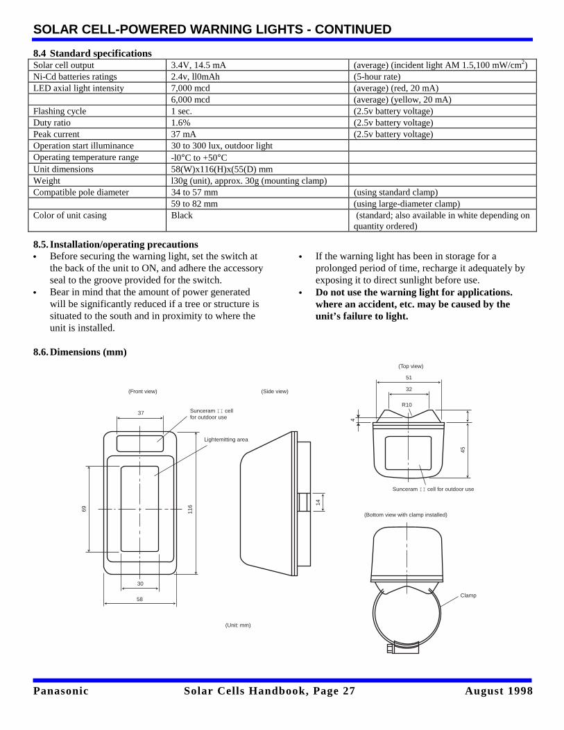
8.4 Standard specificationsSolar cell output 3.4V, 14.5 mA (average) (incident light AM 1.5,100 mW/cm2)Ni-Cd batteries ratings 2.4v, ll0mAh (5-hour rate)LED axial light intensity 7,000 mcd (average) (red, 20 mA)
6,000 mcd (average) (yellow, 20 mA)Flashing cycle 1 sec. (2.5v battery voltage)Duty ratio 1.6% (2.5v battery voltage)Peak current 37 mA (2.5v battery voltage)Operation start illuminance 30 to 300 lux, outdoor lightOperating temperature range -l0°C to +50°CUnit dimensions 58(W)x116(H)x(55(D) mmWeight l30g (unit), approx. 30g (mounting clamp)Compatible pole diameter 34 to 57 mm (using standard clamp)
59 to 82 mm (using large-diameter clamp)Color of unit casing Black (standard; also available in white depending on
quantity ordered)
8.5. Installation/operating precautions• Before securing the warning light, set the switch at
the back of the unit to ON, and adhere the accessoryseal to the groove provided for the switch.
• Bear in mind that the amount of power generatedwill be significantly reduced if a tree or structure issituated to the south and in proximity to where theunit is installed.
• If the warning light has been in storage for aprolonged period of time, recharge it adequately byexposing it to direct sunlight before use.
• Do not use the warning light for applications.where an accident, etc. may be caused by theunit’s failure to light.
8.6. Dimensions (mm)
69 116
Lightemitting area
30
58
37
(Front view)
Sunceram II cellfor outdoor use
(Unit: mm)
(Side view)
14
(Bottom view with clamp installed)
Clamp
(Top view)
4
R10
32
51
45
Sunceram II cell for outdoor use
Panasonic Solar Cells Handbook, Page 28 August 1998
9. SILICON SOLAR MODULES
High conversion efficiency and long-term reliability
9.1. General InformationCrystal system silicon solar modules are attractingattention through the world today primarily as high-efficiency solar cells. This is because high-efficiencysolar modules are capable of converting the radiantenergy of sunlight directly into electrical energy whichis easy to use. Panasonic began marketing crystal siliconsolar modules and solar power supply systems in 1963.We have continued to develop them for use in everyfield, from the home to industry, improving theirperformance and reliability while reducing their cost.We have developed a variety of outdoor power supplydevices for observation, water discharge warningstations and radio relay stations for dam control. Wehave also developed solar clocks which have beeninstalled in more than 4,300 locations worldwide. Ourlatest research and streamlined design systems arehighly regarded in many fields all over the world. This isbecause our work is based on field data from over 10years in a wide variety of solar battery utilization fields.
9.2. Features• High in performance with a module using silicon
cells.• Superb reliability and long-lasting durability to meet
the operating conditions in various naturalenvironments.
9.3. Applications• Independent power supply systems for radio relay
stations, measuring systems, etc.• Large-scale solar power generation systems linked
with commercial power.
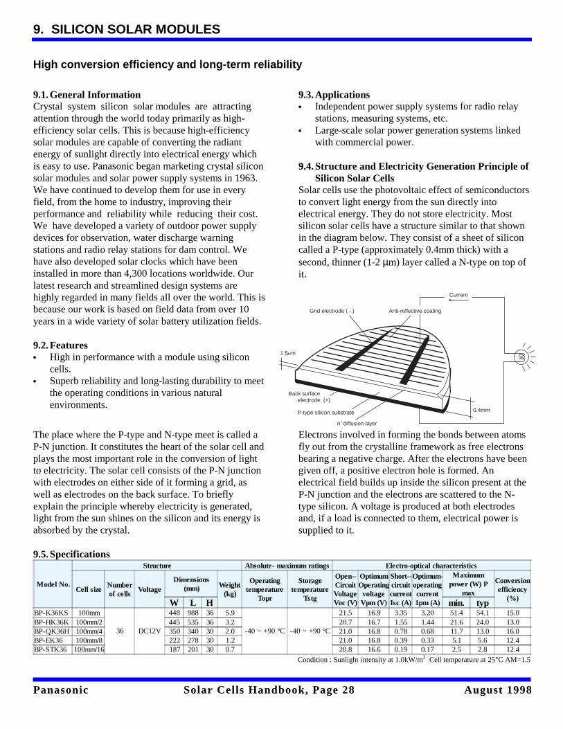
9.4.Structure and Electricity Generation Principle ofSilicon Solar Cells
Solar cells use the photovoltaic effect of semiconductorsto convert light energy from the sun directly intoelectrical energy. They do not store electricity. Mostsilicon solar cells have a structure similar to that shownin the diagram below. They consist of a sheet of siliconcalled a P-type (approximately 0.4mm thick) with asecond, thinner (1-2 µm) layer called a N-type on top ofit.
The place where the P-type and N-type meet is called aP-N junction. It constitutes the heart of the solar cell andplays the most important role in the conversion of lightto electricity. The solar cell consists of the P-N junctionwith electrodes on either side of it forming a grid, aswell as electrodes on the back surface. To brieflyexplain the principle whereby electricity is generated,light from the sun shines on the silicon and its energy isabsorbed by the crystal.
Electrons involved in forming the bonds between atomsfly out from the crystalline framework as free electronsbearing a negative charge. After the electrons have beengiven off, a positive electron hole is formed. Anelectrical field builds up inside the silicon present at theP-N junction and the electrons are scattered to the N-type silicon. A voltage is produced at both electrodesand, if a load is connected to them, electrical power issupplied to it.
9.5. Specifications
Model No.
Structure Absolute- maximum ratings Electro-optical characteristics
Cell sizeNumberof cells
VoltageDimensions
(mm) Weight(kg)
Operatingtemperature
Topr
Storagetemperature
Tstg
Open--CircuitVoltageVoc (V)
OptimumOperatingvoltageVpm (V)
Short--circuitcurrentIsc (A)
Optimum--operatingcurrent1pm (A)
Maximumpower (W) P
max
Conversionefficiency
(%)W L H min. typBP-K36KS 100mm
36 DC12V
448 988 36 5.9
-40 ~ +90 °C -40 ~ +90 °C
21.5 16.9 3.35 3.20 51.4 54.1 15.0BP-HK36K 100mm/2 445 535 36 3.2 20.7 16.7 1.55 1.44 21.6 24.0 13.0BP-QK36H 100mm/4 350 340 30 2.0 21.0 16.8 0.78 0.68 11.7 13.0 16.0BP-EK36 100mm/8 222 278 30 1.2 21.0 16.8 0.39 0.33 5.1 5.6 12.4BP-STK36 100mm/16 187 201 30 0.7 20.8 16.6 0.19 0.17 2.5 2.8 12.4
Condition : Sunlight intensity at 1.0kW/m2 Cell temperature at 25°C AM=1.5
Grid electrode ( - ) Anti-reflective coating
0.4mm
Current
n diffusion layer
P-type silicon substrate
Back surface electrode (+)
1.5 m
+

Panasonic Solar Cells Handbook, Page 29 August 1998
SILICON SOLAR MODULES - CONTINUED
BP-K36KS
BP-HK36K
BP-QK36H
Fixing hole
Terminal boxAl frame
Dimensions : mm
36
448
409
930
988
10- 7
Ope
n-ci
rcui
t vo
ltage
(V
) V
oc
25
20
15
10
5
0
5.0
4.0
3.0
2.0
1.0
0.2 0.4 0.6 0.8 1.0
Light intensity (kW/m )2
Sho
rt-c
ircui
t cur
rent
(A
) Is
c
Tc = 25˚C
Voc
Isc
Operating voltage (V)
Ope
ratin
g-cu
rren
t (A
)
Ee = 1.0kW/m2
0 5 10 15 20 25 30
56˚C
25˚C
4.0
3.5
3.0
2.5
2.0
1.5
1.0
0.5
0
Open-circuit voltage, short-circuit current vs.light intensity Operating-current vs. operating voltage
Fixing hole4 - 7 Terminal box
Al frameDimensions : mm
480535
406
445
36 Ope
n-ci
rcui
t vol
tage
(V
) Voc
25
20
15
10
5
0
2.5
2.0
1.5
1.0
0.5
0.2 0.4 0.6 0.8 1.0
Light intensity (kW/m )2
Sho
rt-c
ircui
t cur
rent
(A
) Is
c
Tc = 25˚C
Voc
Isc
Operating voltage (V)
Ope
ratin
g-cu
rren
t (A
)
Ee = 1.0kW/m2
0 5 10 15 20 25 30
56˚C
25˚C
2.00
1.75
1.50
1.25
1.00
0.75
0.50
0.25
0
Open-circuit voltage, short-circuit current vs.light intensity Operating-current vs. operating voltage
Fixing hole4 - 9.5
Terminal boxAl frame
Dimensions : mm
2034
0
300
3030350290
124
30
20
Ope
n-ci
rcui
t vo
ltage
(V
) V
oc
24
20
16
12
8
4
00.2 0.4 0.6 0.8 1.0
Light intensity (kW/m )2
Sho
rt-c
ircui
t cur
rent
(A
) Is
c
Tc = 25˚C
Voc
Isc
0.9
0.75
0.6
0.45
0.3
0.15
00
Operating voltage (V)
Ope
ratin
g-cu
rren
t (A
)
Ee = 1.0kW/m2
0.9
0.75
0.6
0.45
0.3
0.15
00 4 8 12 16 20 24
56˚C
25˚C
Open-circuit voltage, short-circuit current vs.light intensity Operating-current vs. operating voltage

Panasonic Solar Cells Handbook, Page 30 August 1998
SILICON SOLAR MODULES - CONTINUED
BP-EK36
BP-STK36
Fixing hole4 - 9.5
Terminal boxAl frame
Dimensions : mm
2122
2
180
3030278218
124
30
21
Ope
n-ci
rcui
t vo
ltage
(V
) V
oc
24
20
16
12
8
4
00.2 0.4 0.6 0.8 1.0
Light intensity (kW/m )2
Sho
rt-c
ircui
t cur
rent
(A
) Is
c
Tc = 25˚C
Voc
Isc
0.42
0.35
0.28
0.21
0.14
0.07
00
Ope
n-ci
rcui
t vo
ltage
(V
) V
oc
24
20
16
12
8
4
00.2 0.4 0.6 0.8 1.0
Light intensity (kW/m )2
Sho
rt-c
ircui
t cur
rent
(A
) Is
c
Tc = 25˚C
Voc
Isc
0.24
0.20
0.16
0.12
0.08
0.04
00
Open-circuit voltage, short-circuit current vs.light intensity Operating-current vs. operating voltage
Al frameTerminal box
Fixing holeDimensions : mm
4 - 0 9.5
3030 30201
2118
7
145
Ope
n-ci
rcui
t vo
ltage
(V
) V
oc
24
20
16
12
8
4
00.2 0.4 0.6 0.8 1.0
Light intensity (kW/m )2
Sho
rt-c
ircui
t cur
rent
(A
) Is
c
Tc = 25˚C
Voc
Isc
0.42
0.35
0.28
0.21
0.14
0.07
00
Ope
n-ci
rcui
t vo
ltage
(V
) V
oc
24
20
16
12
8
4
00.2 0.4 0.6 0.8 1.0
Light intensity (kW/m )2
Sho
rt-c
ircui
t cur
rent
(A
) Is
c
Tc = 25˚C
Voc
Isc
0.24
0.20
0.16
0.12
0.08
0.04
00
Open-circuit voltage, short-circuit current vs.light intensity Operating-current vs. operating voltage

Panasonic Solar Cells Handbook, Page 31 August 1998
10. SILICON SOLAR MODULES WITH ARRAY SUPPORTS
Suitable for highly reliable power supplies
10.1. General InformationSolar modules with array supports are often combinedwith storage batteries to create independent powersupplies for applications such as telemeter systems inremote or inaccessible areas, lights to guide shipping,firefighter's radio systems and marine monitoringsystems.Solar module array supports consist of solar modulesselected to match the required power consumption loadand usage conditions, support angle posts, poles to keep
away birds, etc. The solar module array supports areinstalled with the light collecting surface facing duesouth and at an angle of 30 degrees (standard).
10.2 Features• Stands up to the elements for superior reliability
over the long term.• Simple set up and maintenance make it easy to
provide a stable power supply.
10.3 Specifications
Model No.
Output Number ofmodules(series) x(parallel)
Arraysupport
installationmethod
Approximateweight (kg)
External viewand parts
diagram No.Output (W)Output voltage
(V)
54.0 16.9 1 x 1 Rooftop type 15.9 BP-K36KSU1N 1108.0 16.9 (33.8) 1 x 2 (2 x 1) Rooftop type 25.0 BP-K36KSU2N 2162.0 16.9 1 x 3 Rooftop type 41.8 BP-K36KSU3N 324.0 16.7 1 x 1 Rooftop type 8.7 BP-HK36KU1N 411.5 16.8 1 x 1 Rooftop type 6.1 BP-QK36HU1N 554.0 16.9 1 x 1 Panza type 20.0 BP-K36KSP1N
624.0 16.7 1 x 1 Panza type 12.0 BP-HK36KP1N11.5 16.8 1 x 1 Panza type 8.8 BP-QK36HP1N
Panasonic Solar Cells Handbook, Page 32 August 1998
SILICON SOLAR MODULES WITH ARRAY SUPPORTS - CONTINUED
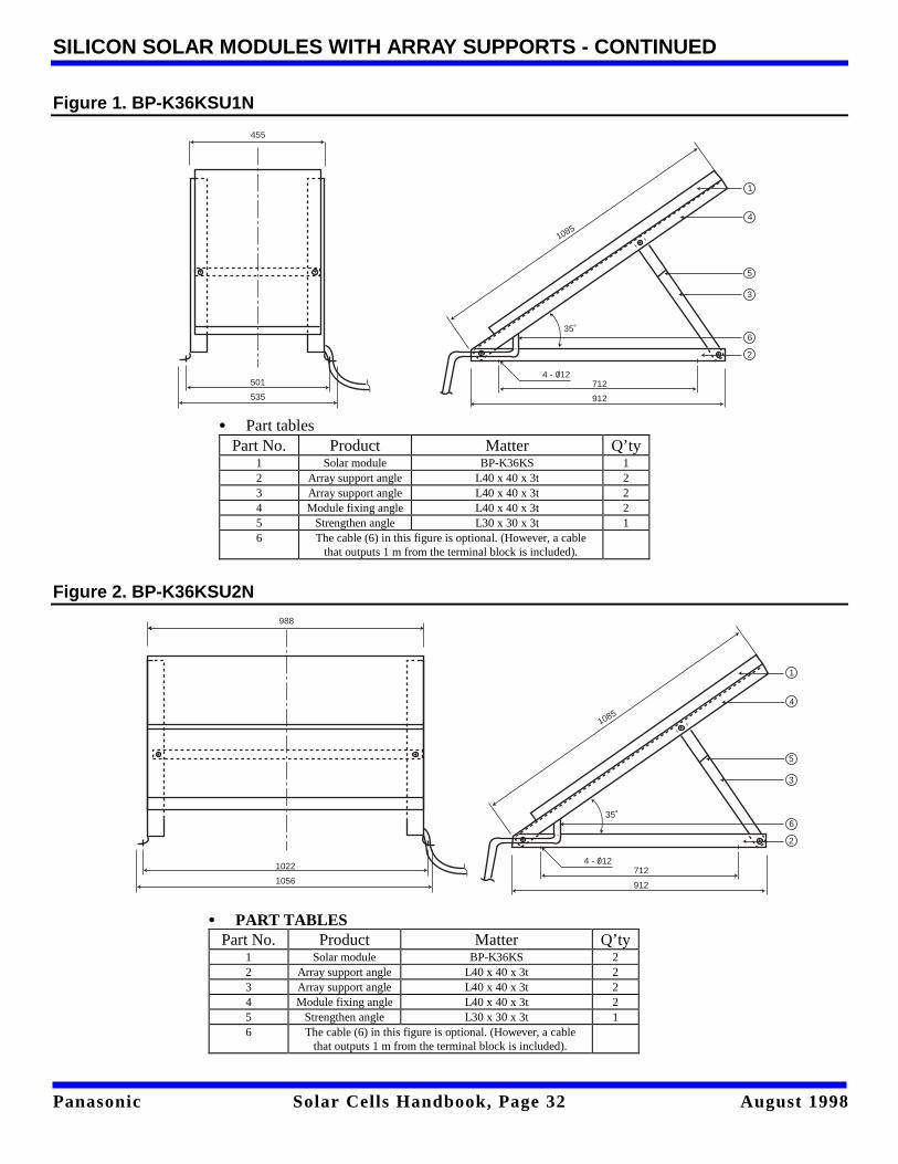
Figure 1. BP-K36KSU1N
Figure 2. BP-K36KSU2N
• Part tables Part No. Product Matter Q’ty
1 Solar module BP-K36KS 1 2 Array support angle L40 x 40 x 3t 2 3 Array support angle L40 x 40 x 3t 2 4 Module fixing angle L40 x 40 x 3t 2 5 Strengthen angle L30 x 30 x 3t 1 6 The cable (6) in this figure is optional. (However, a cable
that outputs 1 m from the terminal block is included).
• PART TABLES Part No. Product Matter Q’ty
1 Solar module BP-K36KS 2 2 Array support angle L40 x 40 x 3t 2 3 Array support angle L40 x 40 x 3t 2 4 Module fixing angle L40 x 40 x 3t 2 5 Strengthen angle L30 x 30 x 3t 1 6 The cable (6) in this figure is optional. (However, a cable
that outputs 1 m from the terminal block is included).
35˚
4 - 012712
912
1085
1
4
5
3
6
2
455
501
535
35˚
4 - 012712
912
1085
1
4
5
3
6
2
988
1022
1056

Panasonic Solar Cells Handbook, Page 33 August 1998
SILICON SOLAR MODULES WITH ARRAY SUPPORTS - CONTINUED
Figure 3. BP-K36KSU3N
Figure 4. BP-HK36KU1N
• Part tables Part No. Product Matter Q’ty
1 Solar module BP-K36KS 3 2 Array support angle L40 x 40 x 3t 2 3 Array support angle L40 x 40 x 3t 2 4 Module fixing angle L50 x 50 x 4t 2 5 Strengthen angle L40 x 40 x 3t 1 6 The cable (6) in this figure is optional. (However, a cable
that outputs 1 m from the terminal block is included).
• PART TABLES Part No. Product Matter Q’ty
1 Solar module BP-HK36K 1 2 Array support angle L30 x 30 x 3t 2 3 Array support angle L30 x 30 x 3t 2 4 Module fixing angle L30 x 30 x 3t 2 5 Strengthen angle SUS304 ∅ 1.5 3 6 The cable (6) in this figure is optional. (However, a cable
that outputs 1 m from the terminal block is included).
1026
1060
988
1495
35˚
848
1248
4- 12
3
4
1
2
5
6
3
4
1
2
5
6
474
500
445
540
35˚
4- 12356
456
Panasonic Solar Cells Handbook, Page 34 August 1998
SILICON SOLAR MODULES WITH ARRAY SUPPORTS - CONTINUED
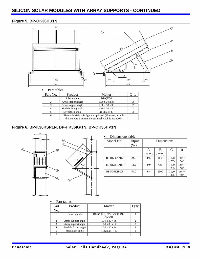
Figure 5. BP-QK36HU1N
Figure 6. BP-K36KSP1N, BP-HK36KP1N, BP-QK36HP1N
340
368
394
35˚
12
350
50 220 50
320
3
4
1
2
5
6
˚
3
4
1
2
5
6
4
C
A
B
• Part tablesPartNo.
Product Matter Q’ty
1 Solar module BP-K36KS, BP-HK36K, BP-QK36H
1
2 Array support angle L30 x 30 x 3t 23 Array support angle L30 x 30 x 3t 24 Module fixing angle L30 x 30 x 3t 45 Strengthen angle SUS304 ∅ 1.5 26
• Dimensions tableModel No. Output
(W)Dimensions
A(mm)
B(mm)
C θ
BP-HK36KP1N 24.0 445 880 ∅120~ 265
30° ~50°
BP-QK36HP1N 11.5 340 645 ∅120~ 265
30° ~50°
BP-K36KSP1N 54.0 448 1500 ∅120~ 265
30° ~50°
• Part tables Part No. Product Matter Q’ty
1 Solar module BP-QK36 1 2 Array support angle L30 x 30 x 3t 2 3 Array support angle L30 x 30 x 3t 2 4 Module fixing angle L30 x 30 x 3t 2 5 Strengthen angle SUS304 ∅ 1.5 3 6 The cable (6) in this figure is optional. (However, a cable
that outputs 1 m from the terminal block is included).
Panasonic Solar Cells Handbook, Page 35 August 1998
11. OVERCHARGE PROTECTION CIRCUITS: DISTRIBUTION PANELS
Suitable for highly reliable power supplies
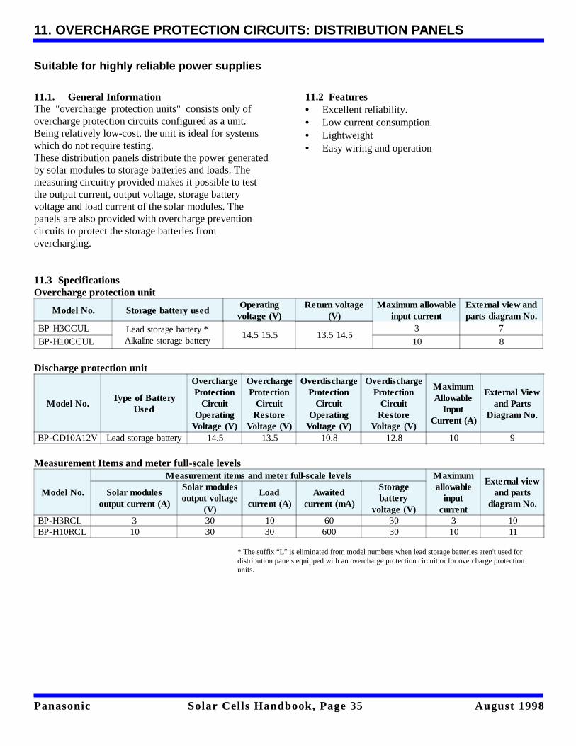
11.1. General InformationThe "overcharge protection units" consists only ofovercharge protection circuits configured as a unit.Being relatively low-cost, the unit is ideal for systemswhich do not require testing.These distribution panels distribute the power generatedby solar modules to storage batteries and loads. Themeasuring circuitry provided makes it possible to testthe output current, output voltage, storage batteryvoltage and load current of the solar modules. Thepanels are also provided with overcharge preventioncircuits to protect the storage batteries fromovercharging.
11.2 Features• Excellent reliability.• Low current consumption.• Lightweight• Easy wiring and operation
11.3 SpecificationsOvercharge protection unit
Model No. Storage battery usedOperatingvoltage (V)
Return voltage(V)
Maximum allowableinput current
External view andparts diagram No.
BP-H3CCUL Lead storage battery *Alkaline storage battery
14.5 15.5 13.5 14.53 7
BP-H10CCUL 10 8
Discharge protection unit
Model No.Type of Battery
Used
OverchargeProtection
CircuitOperating
Voltage (V)
OverchargeProtection
CircuitRestore
Voltage (V)
OverdischargeProtection
CircuitOperating
Voltage (V)
OverdischargeProtection
CircuitRestore
Voltage (V)
MaximumAllowable
InputCurrent (A)
External Viewand Parts
Diagram No.
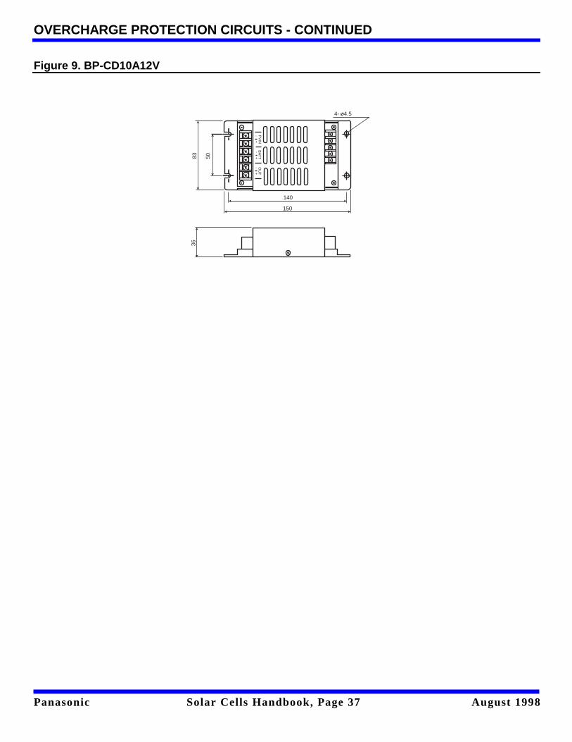
BP-CD10A12V Lead storage battery 14.5 13.5 10.8 12.8 10 9
Measurement Items and meter full-scale levels
Model No.
Measurement items and meter full-scale levels Maximumallowable
inputcurrent
External viewand parts
diagram No.Solar modules
output current (A)
Solar modulesoutput voltage
(V)
Loadcurrent (A)
Awaitedcurrent (mA)
Storagebattery
voltage (V)BP-H3RCL 3 30 10 60 30 3 10BP-H10RCL 10 30 30 600 30 10 11
* The suffix “L” is eliminated from model numbers when lead storage batteries aren't used fordistribution panels equipped with an overcharge protection circuit or for overcharge protectionunits.
Panasonic Solar Cells Handbook, Page 36 August 1998
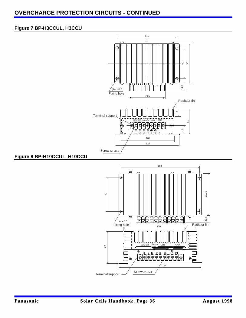
OVERCHARGE PROTECTION CIRCUITS - CONTINUED
Figure 7 BP-H3CCUL, H3CCU
Figure 8 BP-H10CCUL, H10CCU
Fixing hole(4) - 4.5
70.5
14.5
60 80
115
Terminal support
Screw (7) M3.5
1 2 3 4 5 6 7
Solar cellStoragebattery Load GND
105
125
19
51
15
Radiator fin
Solar cell Storage battery
Load GND
194
Screw (7) - M4
Radiator fin170
17.5
Terminal support
77
Fixing hole4- 3.5
100.
5
184
80
Panasonic Solar Cells Handbook, Page 37 August 1998
OVERCHARGE PROTECTION CIRCUITS - CONTINUED
Figure 9. BP-CD10A12V
PV
INB
ATT
OU
T- +
- +- +
4- 4.5
140
150
83 50
36
Panasonic Solar Cells Handbook, Page 38 August 1998
OVERCHARGE PROTECTION CIRCUITS - CONTINUED
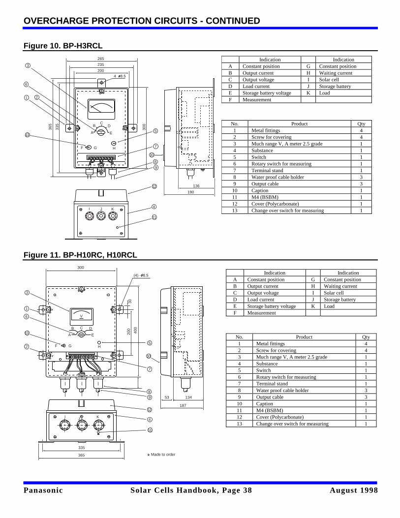
Figure 10. BP-H3RCL
Figure 11. BP-H10RC, H10RCL
Indication IndicationA Constant position G Constant positionB Output current H Waiting currentC Output voltage I Solar cellD Load current J Storage batteryE Storage battery voltage K LoadF Measurement
No. Product Qty1 Metal fittings 42 Screw for covering 43 Much range V, A meter 2.5 grade 14 Substance 15 Switch 16 Rotary switch for measuring 17 Terminal stand 18 Water proof cable holder 39 Output cable 310 Caption 111 M4 (BSBM) 112 Cover (Polycarbonate) 113 Change over switch for measuring 1
A
BC
D
E
F G H
3
4
1 2
5
6
7
8
9
10
11
12
13
365
335
300
265
235
2004 8.5
136
190
I J K
A
B C D
E
HGF
V
I J K
335
365
53 134
187
200
400
(4) - 8.5
300
30
3
4
1
25
6
7
89
10
11
12
13
* Made to order
Indication IndicationA Constant position G Constant positionB Output current H Waiting currentC Output voltage I Solar cellD Load current J Storage batteryE Storage battery voltage K LoadF Measurement
No. Product Qty1 Metal fittings 42 Screw for covering 43 Much range V, A meter 2.5 grade 14 Substance 15 Switch 16 Rotary switch for measuring 17 Terminal stand 18 Water proof cable holder 39 Output cable 310 Caption 111 M4 (BSBM) 112 Cover (Polycarbonate) 113 Change over switch for measuring 1
Panasonic Solar Cells Handbook, Page 39 August 1998
12. SOLAR CELL DESIGN
Solar cells are devices that convert light into electricity,but they do not store electric power. In addition, sincethe actual amount of power produced varies dependingon factors such as the installation conditions andlocation, as well as the weather, there are a fewrequirements which must be borne in mind whendesigning a system. Power supply systems employingsolar cells generally fall into one of the following threecategories.
(1) Direct connection to load(2) Paired with storage battery(3) Paired with commercial power supply
Presented below are a few simple guidelines andequations to aid in the selection of solar cells andstorage batteries, based on the basic systemconfiguration and the load presented by the equipmentto be driven. Panasonic has been conducting research onsolar cell power supply systems for many years and hascollected a voluminous amount of data on the subject.Please consult your Panasonic representative for specificdesign details.
12.1 Solar Cell Power Supply System Basic Configuration
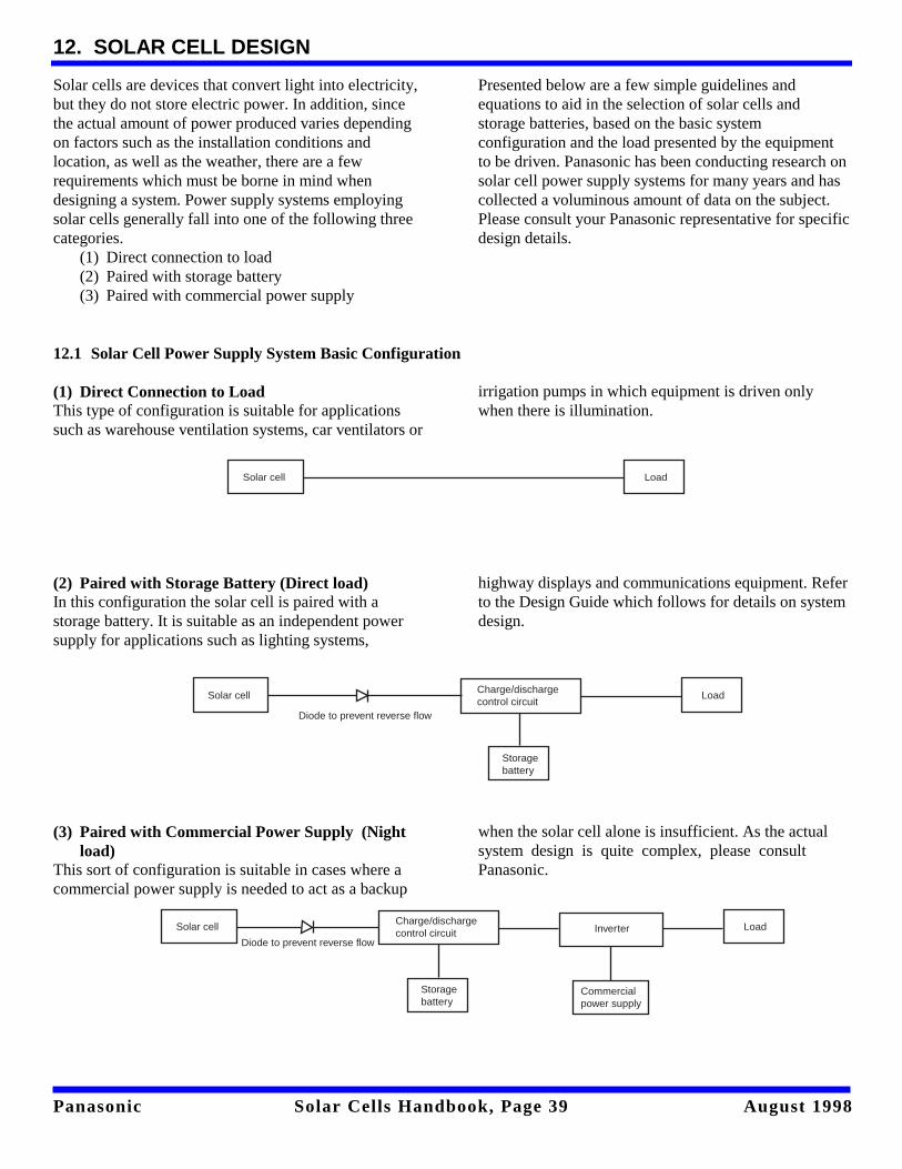
(1) Direct Connection to Load This type of configuration is suitable for applicationssuch as warehouse ventilation systems, car ventilators or
irrigation pumps in which equipment is driven onlywhen there is illumination.
(2) Paired with Storage Battery (Direct load) In this configuration the solar cell is paired with astorage battery. It is suitable as an independent powersupply for applications such as lighting systems,
highway displays and communications equipment. Referto the Design Guide which follows for details on systemdesign.
(3) Paired with Commercial Power Supply (Night
load)This sort of configuration is suitable in cases where acommercial power supply is needed to act as a backup
when the solar cell alone is insufficient. As the actualsystem design is quite complex, please consultPanasonic.
Solar cell Load
Solar cell LoadCharge/dischargecontrol circuit
Storagebattery
Diode to prevent reverse flow
Solar cell LoadCharge/dischargecontrol circuit
Storagebattery
Diode to prevent reverse flowInverter
Commercialpower supply
Panasonic Solar Cells Handbook, Page 40 August 1998
SOLAR CELL DESIGN - CONTINUED
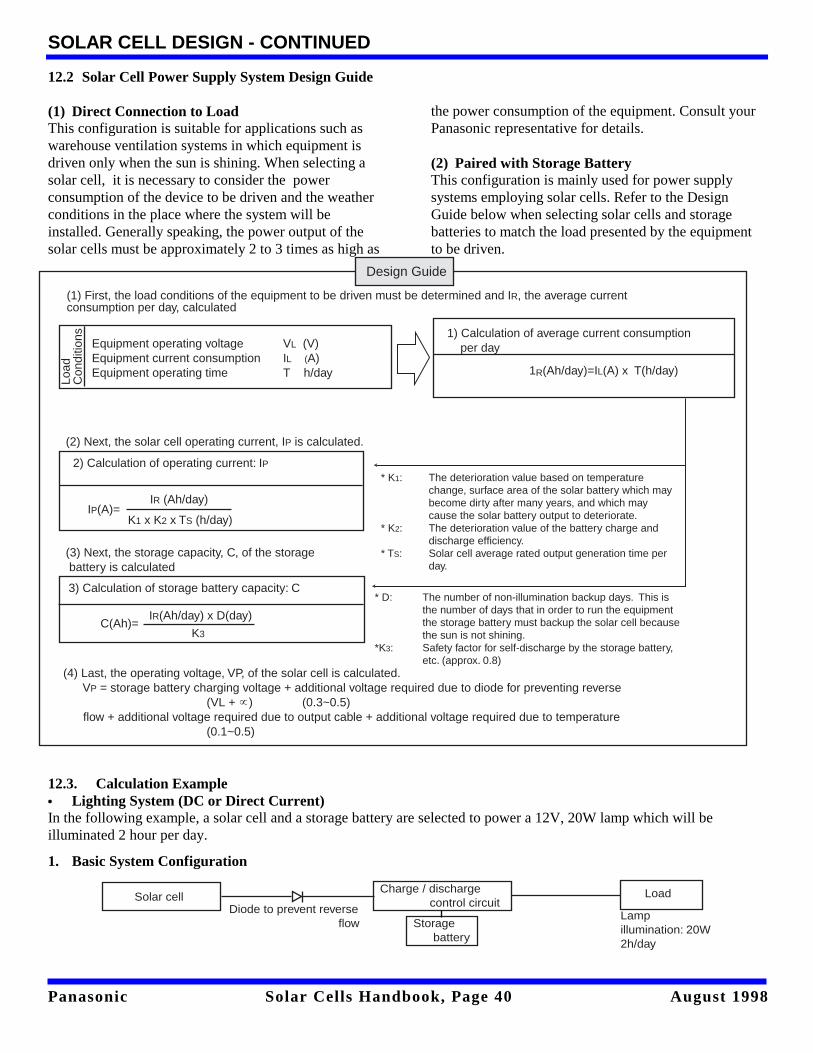
12.2 Solar Cell Power Supply System Design Guide
(1) Direct Connection to Load This configuration is suitable for applications such aswarehouse ventilation systems in which equipment isdriven only when the sun is shining. When selecting asolar cell, it is necessary to consider the powerconsumption of the device to be driven and the weatherconditions in the place where the system will beinstalled. Generally speaking, the power output of thesolar cells must be approximately 2 to 3 times as high as
the power consumption of the equipment. Consult yourPanasonic representative for details. (2) Paired with Storage BatteryThis configuration is mainly used for power supplysystems employing solar cells. Refer to the DesignGuide below when selecting solar cells and storagebatteries to match the load presented by the equipmentto be driven.
12.3. Calculation Example• Lighting System (DC or Direct Current)In the following example, a solar cell and a storage battery are selected to power a 12V, 20W lamp which will beilluminated 2 hour per day.
1. Basic System Configuration
(1) First, the load conditions of the equipment to be driven must be determined and IR, the average currentconsumption per day, calculated
1) Calculation of average current consumption per day
1R(Ah/day)=IL(A) x T(h/day)
Equipment operating voltage VL (V)Equipment current consumption IL (A)Equipment operating time T h/day
2) Calculation of operating current: IP
3) Calculation of storage battery capacity: C
(4) Last, the operating voltage, VP, of the solar cell is calculated. VP = storage battery charging voltage + additional voltage required due to diode for preventing reverse
(VL + ) (0.3~0.5) flow + additional voltage required due to output cable + additional voltage required due to temperature
(0.1~0.5)
C(Ah)= IR(Ah/day) x D(day)
K3
IP(A)= IR (Ah/day)
K1 x K2 x TS (h/day)
Load
Con
ditio
ns
(2) Next, the solar cell operating current, IP is calculated.
(3) Next, the storage capacity, C, of the storage battery is calculated
* K1: The deterioration value based on temperature change, surface area of the solar battery which maybecome dirty after many years, and which may cause the solar battery output to deteriorate.
* K2: The deterioration value of the battery charge anddischarge efficiency.
* TS: Solar cell average rated output generation time perday.
* D: The number of non-illumination backup days. This is the number of days that in order to run the equipmentthe storage battery must backup the solar cell becausethe sun is not shining.
*K3: Safety factor for self-discharge by the storage battery, etc. (approx. 0.8)
Design Guide
Diode to prevent reverse flow
Solar cellCharge / discharge control circuit
Storage battery
Load
Lampillumination: 20W2h/day
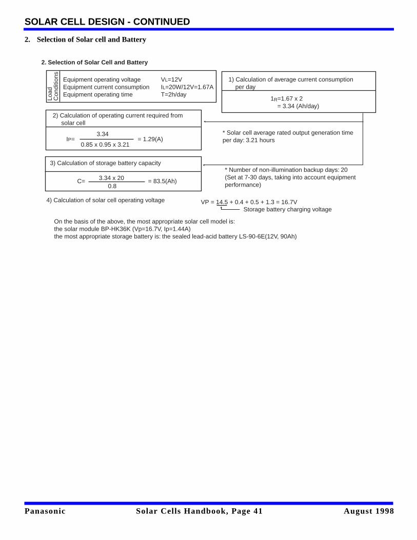
Panasonic Solar Cells Handbook, Page 41 August 1998
SOLAR CELL DESIGN - CONTINUED
2. Selection of Solar cell and Battery
1) Calculation of average current consumption per day
1R=1.67 x 2 = 3.34 (Ah/day)
Equipment operating voltage VL=12VEquipment current consumption IL=20W/12V=1.67AEquipment operating time T=2h/day
2. Selection of Solar Cell and Battery
2) Calculation of operating current required from solar cell
3) Calculation of storage battery capacity
4) Calculation of solar cell operating voltage
On the basis of the above, the most appropriate solar cell model is:the solar module BP-HK36K (Vp=16.7V, Ip=1.44A)the most appropriate storage battery is: the sealed lead-acid battery LS-90-6E(12V, 90Ah)
* Number of non-illumination backup days: 20(Set at 7-30 days, taking into account equipment performance)
* Solar cell average rated output generation timeper day: 3.21 hours
C= = 83.5(Ah)3.34 x 200.8
IP= = 1.29(A)3.34
0.85 x 0.95 x 3.21
VP = 14.5 + 0.4 + 0.5 + 1.3 = 16.7VStorage battery charging voltage
Load
Con
ditio
ns
Related Documents