Simplified approximate method for analysis of rocking systems accounting for soil inelasticity and foundation uplifting I. Anastasopoulos a,n,1 , Th. Kontoroupi b,1 a Division of Civil Engineering, University of Dundee, United Kingdom b Department of Civil Engineering and Engineering Mechanics, Columbia University, United States article info Article history: Received 22 October 2012 Received in revised form 25 September 2013 Accepted 1 October 2013 Keywords: Rocking foundation Nonlinear analysis Simplified method Soil–structure interaction abstract A simplified approximate method to analyze the rocking response of SDOF systems lying on compliant soil is introduced, accounting for soil inelasticity and foundation uplifting. The soil–foundation system is replaced by a nonlinear rotational spring, accompanied by a linear rotational dashpot, and linear horizontal and vertical springs and dashpots. Considering a square footing on clay under undrained conditions, the necessary moment–rotation (M–θ) relations are computed through monotonic pushover finite element (FE) analyses, employing a thoroughly-validated constitutive model. Cyclic pushover analyses are performed to compute the damping–rotation (C R –θ) relations, necessary to calibrate the rotational dashpot, and the settlement–rotation (Δw–θ) relations, required to estimate the dynamic settlement. The effectiveness of the simplified method is verified through dynamic time history analyses, comparing its predictions with the results of 3D FE analyses. The simplified method is shown to capture the entire rotation time history θ(t) with adequate accuracy. The latter is used to compute the time history of dynamic settlement w(t), employing a simplified approximate procedure. The proposed simplified method should, by no means, be considered a substitute for more sophisticated analysis methods. However, despite its limitations, it may be utilized for (at least preliminary) design purposes. & 2013 Elsevier Ltd. All rights reserved. 1. Introduction Soil–foundation–structure interaction (SFSI) has been the object of extensive research over the last decades in an attempt to gain deeper insight into the seismic performance of structures (e.g., [35,59,36,21,57,61,22]). Nevertheless, a principal goal of foundation design, as entrenched in current seismic codes, is to maintain “elastic” soil–foundation response. According to capacity design principles, full mobilization of strength in the foundation is prevented, by guiding failure onto the superstructure (through application of appropriate over-strength factors). Strong earth- quakes over the last 20 years, though, have shown that inelastic soil–foundation response may be inevitable. In fact, seismic records from the earthquakes of Northridge (1994) and Kobe (1995) have proved that very high levels of PGA and PGV can be experienced in near-fault zones. The recent Tohoku (2011) earth- quake is another example of dramatically strong recorded PGA of up to 3 g [17]. Apparently, under such severe seismic shaking the assumption of elastic soil–foundation response cannot be considered realistic. Yet, it has been suggested by a growing body of researchers that soil–foundation nonlinear response may have a beneficial effect on the superstructure and it should be therefore considered in design (e.g., [50,24,53,18,46,54,32,19,3,2,27,28,38,39]). Nonlinear founda- tion behavior may involve sliding and/or uplifting of the foundation from the supporting soil, and/or mobilization of soil bearing capacity. In any of these cases, the finite capacity of the foundation may act as “rocking isolation” [46], limiting the inertia forces transmitted onto the superstructure, thus protecting it against seismic motions exceeding its design. Besides, such a design alternative offers greater safety margins in terms of ductility, since it exploits the inherent ductility associated with progressive soil failure. To this end, an urgent need is arising to explicitly account for nonlinear SFSI and its beneficial effects in modern seismic design. Nonlinear foundation response could be allowed during strong seismic shaking, while ensuring that the developing displacements and rotations will not jeopardize the structural integrity of the superstructure. So far, a substantial amount of research has been conducted, including experimental (e.g. [45,18,41,37,9,51,19]) and analytical studies: (i) finite element (FE) or boundary element approaches, in which both the structure and the soil are modeled together in one single system through an assemblage of elements (e.g. [11,10,58,44,31,23,30]); (ii) rigorous plasticity-based macro- element formulations (e.g., [49,50,43,13,12,16]); (iii) Winkler-based Contents lists available at ScienceDirect journal homepage: www.elsevier.com/locate/soildyn Soil Dynamics and Earthquake Engineering 0267-7261/$ - see front matter & 2013 Elsevier Ltd. All rights reserved. http://dx.doi.org/10.1016/j.soildyn.2013.10.001 n Corresponding author. Tel.: þ44 1382 385720; fax: þ44 1382 384816. E-mail addresses: [email protected], [email protected] (I. Anastasopoulos). 1 Formerly National Technical University of Athens, Greece. Soil Dynamics and Earthquake Engineering 56 (2014) 28–43

Welcome message from author
This document is posted to help you gain knowledge. Please leave a comment to let me know what you think about it! Share it to your friends and learn new things together.
Transcript

Simplified approximate method for analysis of rocking systemsaccounting for soil inelasticity and foundation uplifting
I. Anastasopoulos a,n,1, Th. Kontoroupi b,1
a Division of Civil Engineering, University of Dundee, United Kingdomb Department of Civil Engineering and Engineering Mechanics, Columbia University, United States
a r t i c l e i n f o
Article history:Received 22 October 2012Received in revised form25 September 2013Accepted 1 October 2013
Keywords:Rocking foundationNonlinear analysisSimplified methodSoil–structure interaction
a b s t r a c t
A simplified approximate method to analyze the rocking response of SDOF systems lying on compliantsoil is introduced, accounting for soil inelasticity and foundation uplifting. The soil–foundation system isreplaced by a nonlinear rotational spring, accompanied by a linear rotational dashpot, and linearhorizontal and vertical springs and dashpots. Considering a square footing on clay under undrainedconditions, the necessary moment–rotation (M–θ) relations are computed through monotonic pushoverfinite element (FE) analyses, employing a thoroughly-validated constitutive model. Cyclic pushoveranalyses are performed to compute the damping–rotation (CR–θ) relations, necessary to calibrate therotational dashpot, and the settlement–rotation (Δw–θ) relations, required to estimate the dynamicsettlement. The effectiveness of the simplified method is verified through dynamic time history analyses,comparing its predictions with the results of 3D FE analyses. The simplified method is shown to capturethe entire rotation time history θ(t) with adequate accuracy. The latter is used to compute the timehistory of dynamic settlement w(t), employing a simplified approximate procedure. The proposedsimplified method should, by no means, be considered a substitute for more sophisticated analysismethods. However, despite its limitations, it may be utilized for (at least preliminary) design purposes.
& 2013 Elsevier Ltd. All rights reserved.
1. Introduction
Soil–foundation–structure interaction (SFSI) has been theobject of extensive research over the last decades in an attemptto gain deeper insight into the seismic performance of structures(e.g., [35,59,36,21,57,61,22]). Nevertheless, a principal goal offoundation design, as entrenched in current seismic codes, is tomaintain “elastic” soil–foundation response. According to capacitydesign principles, full mobilization of strength in the foundation isprevented, by guiding failure onto the superstructure (throughapplication of appropriate over-strength factors). Strong earth-quakes over the last 20 years, though, have shown that inelasticsoil–foundation response may be inevitable. In fact, seismicrecords from the earthquakes of Northridge (1994) and Kobe(1995) have proved that very high levels of PGA and PGV can beexperienced in near-fault zones. The recent Tohoku (2011) earth-quake is another example of dramatically strong recorded PGA ofup to 3 g [17].
Apparently, under such severe seismic shaking the assumptionof elastic soil–foundation response cannot be considered realistic.
Yet, it has been suggested by a growing body of researchers thatsoil–foundation nonlinear response may have a beneficial effect onthe superstructure and it should be therefore considered in design(e.g., [50,24,53,18,46,54,32,19,3,2,27,28,38,39]). Nonlinear founda-tion behavior may involve sliding and/or uplifting of the foundationfrom the supporting soil, and/or mobilization of soil bearingcapacity. In any of these cases, the finite capacity of the foundationmay act as “rocking isolation” [46], limiting the inertia forcestransmitted onto the superstructure, thus protecting it againstseismic motions exceeding its design. Besides, such a designalternative offers greater safety margins in terms of ductility, sinceit exploits the inherent ductility associated with progressive soilfailure.
To this end, an urgent need is arising to explicitly account fornonlinear SFSI and its beneficial effects in modern seismic design.Nonlinear foundation response could be allowed during strongseismic shaking, while ensuring that the developing displacementsand rotations will not jeopardize the structural integrity of thesuperstructure. So far, a substantial amount of research has beenconducted, including experimental (e.g. [45,18,41,37,9,51,19]) andanalytical studies: (i) finite element (FE) or boundary elementapproaches, in which both the structure and the soil are modeledtogether in one single system through an assemblage of elements(e.g. [11,10,58,44,31,23,30]); (ii) rigorous plasticity-based macro-element formulations (e.g., [49,50,43,13,12,16]); (iii) Winkler-based
Contents lists available at ScienceDirect
journal homepage: www.elsevier.com/locate/soildyn
Soil Dynamics and Earthquake Engineering
0267-7261/$ - see front matter & 2013 Elsevier Ltd. All rights reserved.http://dx.doi.org/10.1016/j.soildyn.2013.10.001
n Corresponding author. Tel.: þ44 1382 385720; fax: þ44 1382 384816.E-mail addresses: [email protected],
[email protected] (I. Anastasopoulos).1 Formerly National Technical University of Athens, Greece.
Soil Dynamics and Earthquake Engineering 56 (2014) 28–43
approaches, where the soil is replaced by a series of distributednonlinear springs and dashpots (e.g., [33,1,56]); and (iv) simplifiedapproaches, such as the iterative procedure proposed by Paolucciet al. [52] to be incorporated to the Direct Displacement-BasedDesign (DDBD) method [55].
Nonlinear FE simulation, where both the superstructure and thesoil–foundation system are modeled as a whole, is probably one ofthe best ways to simulate the response of rocking-isolated systems.However, such an approach is not computationally efficient andrequires (reasonably) sophisticated and adequately validated consti-tutive models, rendering its application difficult in everyday engi-neering practice. Meanwhile, the current state-of-the art in nonlinearanalysis of foundations emphasizes the development of macro-element models. According to this approach, the entire soil-foundation system is replaced by a single element, capable ofportraying the rocking response in terms of rotation and dynamicsettlement. However, the developed macro-element models have notyet been introduced in commercial FE codes and therefore, their useis limited. Moreover, extensive calibration is required in order toproduce ready-to-use parameter “libraries” – a major issue thatshould be addressed in order to encourage their use in practice.
On the other hand, simplified methods that account for non-linear SFSI, such as the procedure proposed by Paolucci et al. [52],may have substantial benefits, including: (i) easy implementationin commercial numerical analysis codes; (ii) limited calibrationrequirements; and (iii) applicability by non-specialists. Moreover,such simplified consideration of the nonlinear response of the soil-foundation system allows for more detailed and realistic modelingof the superstructure, which is likely to be a key issue in real-lifeengineering projects. Last but not least, by avoiding complicated3D FE modeling, great savings in terms of computation time can beachieved. Consequently, the development of simplified approachesto account for nonlinear SFSI is of paramount importance in orderto facilitate the application of such novel seismic design conceptsin engineering practice.
Aiming to overcome the aforementioned barriers concerningthe existing more sophisticated methods of analysis (such asmacro-elements and 3D FE modeling), and to provide a frameworkfor future research on the subject, this paper introduces asimplified approximate method to simulate the seismic responseof a system rocking on compliant soil, accounting for fully inelastic
soil response and geometric nonlinearities (such as foundationuplifting and second order effects). To demonstrate its effective-ness, the proposed simplified method is applied to a single degreeof freedom (SDOF) system, representative of a bridge pier, compar-ing the predicted response with the results of more rigorous 3D FEanalyses. The introduced simplified analysis method should, by nomeans, be viewed as capable of reproducing all aspects of complexsoil response, or as a substitute of more elaborate methods.However, despite its limitations, it may be utilized for (at leastpreliminary) design purposes.
2. Problem definition and outline of the simplified method
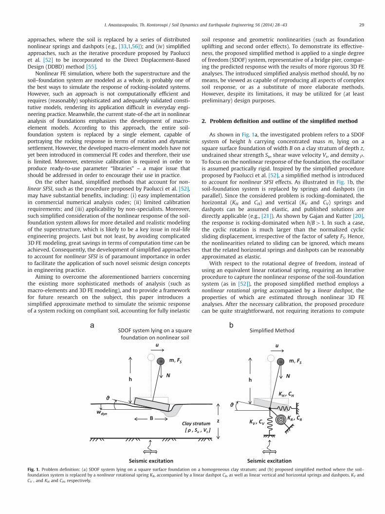
As shown in Fig. 1a, the investigated problem refers to a SDOFsystem of height h carrying concentrated mass m, lying on asquare surface foundation of width B on a clay stratum of depth z,undrained shear strength Su, shear wave velocity Vs, and density ρ.To focus on the nonlinear response of the foundation, the oscillatoris assumed practically rigid. Inspired by the simplified procedureproposed by Paolucci et al. [52], a simplified method is introducedto account for nonlinear SFSI effects. As illustrated in Fig. 1b, thesoil-foundation system is replaced by springs and dashpots (inparallel). Since the considered problem is rocking-dominated, thehorizontal (KH and CH) and vertical (KV and CV) springs anddashpots can be assumed elastic, and published solutions aredirectly applicable (e.g., [21]). As shown by Gajan and Kutter [20],the response is rocking-dominated when h/B41. In such a case,the cyclic rotation is much larger than the normalized cyclicsliding displacement, irrespective of the factor of safety FS. Hence,the nonlinearities related to sliding can be ignored, which meansthat the related horizontal springs and dashpots can be reasonablyapproximated as elastic.
With respect to the rotational degree of freedom, instead ofusing an equivalent linear rotational spring, requiring an iterativeprocedure to capture the nonlinear response of the soil-foundationsystem (as in [52]), the proposed simplified method employs anonlinear rotational spring accompanied by a linear dashpot, theproperties of which are estimated through nonlinear 3D FEanalyses. After the necessary calibration, the proposed procedurecan be quite straightforward, not requiring iterations to compute
Fig. 1. Problem definition: (a) SDOF system lying on a square surface foundation on a homogeneous clay stratum; and (b) proposed simplified method where the soil–foundation system is replaced by a nonlinear rotational spring KR, accompanied by a linear dashpot CR, as well as linear vertical and horizontal springs and dashpots, KV andCV , and KH and CH, respectively.
I. Anastasopoulos, Th. Kontoroupi / Soil Dynamics and Earthquake Engineering 56 (2014) 28–43 29
the response of the rocking foundation–structure system. Sincesuch elements can be easily introduced in commercial FE codes,capable of performing dynamic time history analyses, the pro-posed methodology can be easily applicable in practice, withoutrequiring calibration of sophisticated models and avoiding theneed for time consuming 3D FE analyses. As it will be shown lateron, the proposed method may capture with adequate accuracy theentire rotation time history θ(t). The latter is used to compute thetime history of dynamic settlement w(t), employing a simplifiedapproximate procedure, also based on FE analysis results. A similarprocedure had been earlier postulated by Kutter et al. [42] andDeng et al. [14], who suggested that the settlement can becorrelated with the rotation time history θ(t).
In order to implement the proposed method, three relations arerequired, all of them being a function of the factor of safety againstvertical loads FS ¼Nuo=N, where Nuo is the bearing capacity of thefooting under purely vertical loading, and N ¼ mg is the verticalload due to the mass of the superstructure (assuming that thefooting is massless): (a) the moment–rotation (M–θ) relation,required to define the nonlinear rotational spring KR; (b) thedamping coefficient–rotation (CR–θ) relation, required to definethe rotational dashpot CR; and (c) the dynamic settlement–rota-tion (Δwdyn–θ) relation, required to compute the settlement. Thethree necessary relations are computed employing the FE method,applying a thoroughly validated soil constitutive model [4], andfocusing on square shallow foundations. The same methodologycan be employed for other footing shapes (rectangular, circular,strip), or for embedded foundations (see also [25]). Alternatively,the required relations can be produced experimentally, on the basisof cyclic pushover tests (e.g., [40,18,5]). Thus, the practicingengineer may directly apply the proposed methodology utilizingthe provided FE-derived relations, or select from the literatureother relations that may be considered more appropriate.
The vertical component of the seismic motion has not beenincluded in the analyses, and its effect on settlement accumulationcannot be addressed through the presented simplified method.Although this is clearly a limitation of the proposed simplifiedanalysis method, it is not expected to have an appreciable effect onthe response, at least as far as the natural vertical component ofthe earthquake is concerned. The latter is typically of much higherfrequency and not correlated to the horizontal component. Itseffect has been shown to be of minimal importance in Kourkouliset al. [39], using a 2-storey rocking-isolated frame structure as anexample. However, a valley-generated parasitic vertical compo-nent can be detrimental for overlying structures, and its effectshould be taken into account. In contrast to the natural verticalcomponent, being a direct result of geometry, it is fully correlatedand of practically the same dominant period with the horizontalcomponent [26], and can therefore have a detrimental effect onsystem performance and the accumulated settlements.
3. Numerical analysis methodology
The three necessary relations (M–θ, CR–θ, and Δw–θ) are derivedthrough 3D FE analysis of the foundation–structure system. The M–θrelations are computed on the basis of displacement-controlledmonotonic pushover analyses; cyclic pushover analyses are con-ducted to derive the CR–θ and Δw–θ relations. Then, the seismicperformance of the rocking system is computed through dynamictime history analysis: (a) employing the 3D FE model of the soil–foundation–structure system; and (b) applying the proposedsimplified method. The results of the two approaches are com-pared to verify the effectiveness of the simplified method, and toderive insights on the main factors affecting the response.
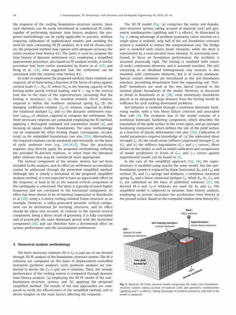
The 3D FE model (Fig. 1a) comprises the entire soil–founda-tion–structure system, taking account of material (soil) and geo-metric nonlinearities (uplifting and P–Δ effects). As illustrated inFig. 2, taking advantage of problem symmetry (since rotation on asingle plane is studied), only half of the soil–foundation–structuresystem is modeled to reduce the computational cost. The bridgepier is modeled with elastic beam elements, while the deck isrepresented by a concentrated mass element. As previously men-tioned, to focus on foundation performance, the oscillator isassumed practically rigid. The footing is modeled with elastic(8-node) continuum elements, and is assumed massless. The soil,consisting of an idealized homogeneous clay stratum, is alsomodeled with continuum elements, but is of course nonlinear.Special contact elements are introduced at the soil–foundationinterface, permitting detachment from the supporting soil. “Free-field” boundaries are used at the two lateral (normal to therotation plane) boundaries of the model. However, as discussedin detail in Kourkoulis et al. [38], even elementary boundariesplaced at an adequately large distance from the footing would besufficient for such rocking-dominated problems.
Soil behavior is modeled through a nonlinear kinematic hard-ening model, with a Von Mises failure criterion and associatedflow rule [4]. The evolution law of the model consists of anonlinear kinematic hardening component, which describes thetranslation of the yield surface in the stress space, and an isotropichardening component, which defines the size of the yield surfaceas a function of plastic deformation (see also [29]). Calibration ofmodel parameters requires knowledge of: (a) the undrained shearstrength Su; (b) the small-strain stiffness (expressed through Go orVs); and (c) the stiffness degradation (G–γ and ξ–γ curves). Moredetails on the model, as well as model calibration and comparisonsof model predictions in terms of G–γ and ξ–γ curves againstexperimental results can be found in [4].
In the case of the simplified approach (Fig. 1b), the super-structure is modeled using exactly the same model, but the soil–foundation system is replaced by linear horizontal (KH and CH) andvertical (KV and CV) springs and dashpots, a nonlinear rotationalspring KR, and a linear rotational dashpot CR. While KH, KV, CH, andCV are calibrated on the basis of published solutions [21], thederived M–θ and CR–θ relations are used for KR and CR. Thesimplified model is subjected to dynamic time history analysis,employing as seismic excitation the acceleration time history atthe ground surface. Based on the computed rotation time history θ(t),
Fig. 2. Rigorous 3D finite element model comprising the entire soil–foundation–structure system, taking account of material (soil) and geometric nonlinearities(uplifting and P–Δ effects). Taking advantage of problem symmetry, only half of themodel is analyzed.
I. Anastasopoulos, Th. Kontoroupi / Soil Dynamics and Earthquake Engineering 56 (2014) 28–4330
and the derived Δw–θ relations, a simplified procedure is employed tocompute the settlement time history w(t).
3.1. Model validation
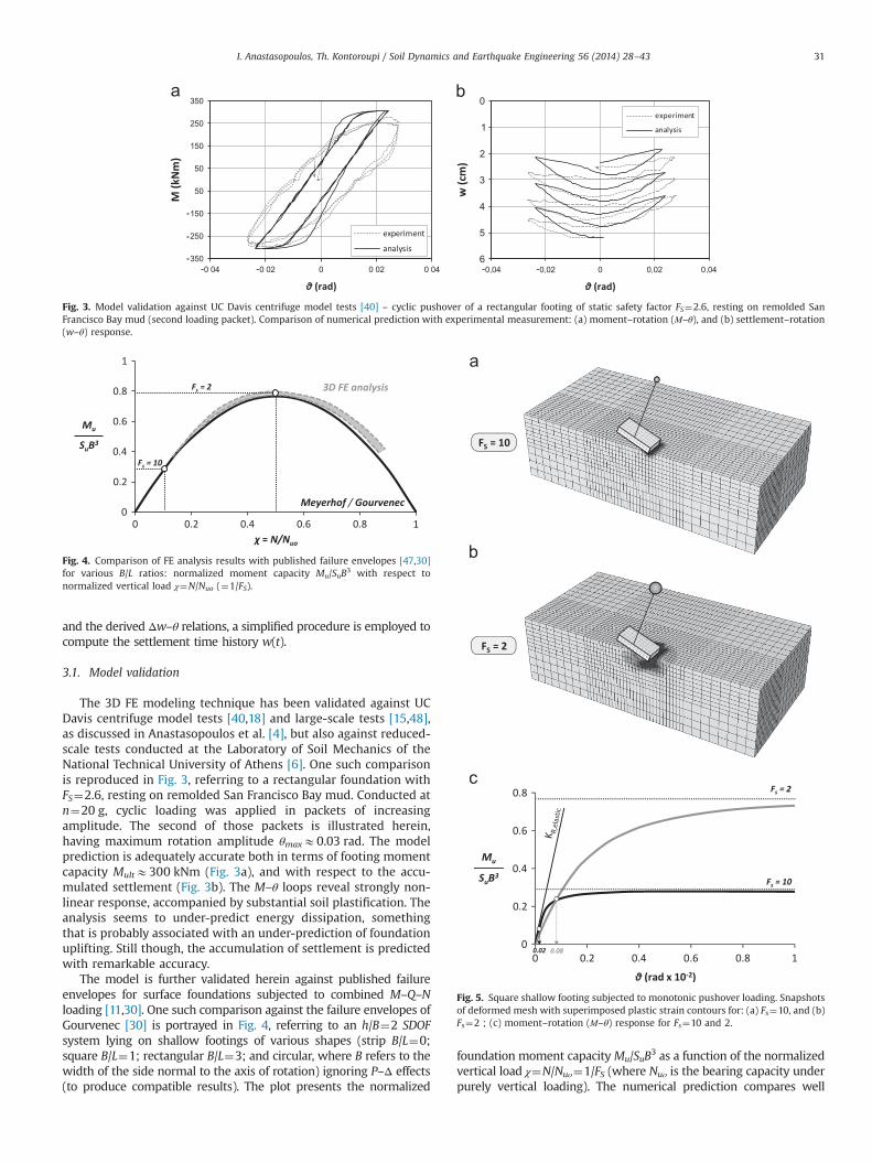
The 3D FE modeling technique has been validated against UCDavis centrifuge model tests [40,18] and large-scale tests [15,48],as discussed in Anastasopoulos et al. [4], but also against reduced-scale tests conducted at the Laboratory of Soil Mechanics of theNational Technical University of Athens [6]. One such comparisonis reproduced in Fig. 3, referring to a rectangular foundation withFS¼2.6, resting on remolded San Francisco Bay mud. Conducted atn¼20 g, cyclic loading was applied in packets of increasingamplitude. The second of those packets is illustrated herein,having maximum rotation amplitude θmaxE0.03 rad. The modelprediction is adequately accurate both in terms of footing momentcapacity MultE300 kNm (Fig. 3a), and with respect to the accu-mulated settlement (Fig. 3b). The M–θ loops reveal strongly non-linear response, accompanied by substantial soil plastification. Theanalysis seems to under-predict energy dissipation, somethingthat is probably associated with an under-prediction of foundationuplifting. Still though, the accumulation of settlement is predictedwith remarkable accuracy.
The model is further validated herein against published failureenvelopes for surface foundations subjected to combined M–Q–Nloading [11,30]. One such comparison against the failure envelopes ofGourvenec [30] is portrayed in Fig. 4, referring to an h/B¼2 SDOFsystem lying on shallow footings of various shapes (strip B/L¼0;square B/L¼1; rectangular B/L¼3; and circular, where B refers to thewidth of the side normal to the axis of rotation) ignoring P–Δ effects(to produce compatible results). The plot presents the normalized
foundation moment capacityMu/SuB3 as a function of the normalizedvertical load χ¼N/Nuο¼1/FS (where Nuο is the bearing capacity underpurely vertical loading). The numerical prediction compares well
Fig. 3. Model validation against UC Davis centrifuge model tests [40] – cyclic pushover of a rectangular footing of static safety factor FS¼2.6, resting on remolded SanFrancisco Bay mud (second loading packet). Comparison of numerical prediction with experimental measurement: (a) moment–rotation (Μ–θ), and (b) settlement–rotation(w–θ) response.
Fig. 4. Comparison of FE analysis results with published failure envelopes [47,30]for various B/L ratios: normalized moment capacity Mu/SuB3 with respect tonormalized vertical load χ¼N/Nuo (¼1/FS).
Fig. 5. Square shallow footing subjected to monotonic pushover loading. Snapshotsof deformed mesh with superimposed plastic strain contours for: (a) Fs¼10, and (b)Fs¼2 ; (c) moment–rotation (Μ–θ) response for Fs¼10 and 2.
I. Anastasopoulos, Th. Kontoroupi / Soil Dynamics and Earthquake Engineering 56 (2014) 28–43 31
with the classic solution of Meyerhof [47], overestimatingMu/SuB3 byabout 10% for χ40.3 (i.e., for FSo3). Ignoring P–Δ effects, themoment capacity of the foundation is maximized for a critical valueof the safety factor against vertical loads FS¼2 (χ¼0.5).
Admittedly, the model employed herein has not yet beenvalidated for all possible combinations of moment to shear ratio,embedment depth, and footing shape. While there is a breadth offailure envelopes in the literature, the experimental data dealingwith cyclic or dynamic loading are much more limited. Specificcases have been tested experimentally, and only these can and havebeen used for validation as summarized in Anastasopoulos et al. [7].
4. Moment–rotation relations
TheM–θ relations are computed through displacement-controlledmonotonic pushover analyses, utilizing the previously presented 3DFE model. To derive results of generalized applicability, the analysis isconducted following the dimensional formulation presented inKourkoulis et al. [38]. The FE analyses are conducted for differentfactors of safety against vertical loading FS¼2, 2.5, 3.3, 5, and 10(corresponding to χ¼Ν/Nuο¼0.5, 0.4, 0.3, 0.2, and 0.1). Static factorsof safety FSo2 are rarely applied in practice (to limit settlement),and are therefore not considered herein. On the other hand, forFS410 the rocking response is almost purely uplifting-dominated,with soil inelasticity playing only a minor role. For the case of clay,this has been shown in Gazetas et al. (2013). In the case of sand, soilnonlinearity may be important even for much larger FS. All of theresults presented herein refer to a relatively slender system, havinga slenderness ratio h/B¼2 (corresponding to a slenderness ratioH/B¼4 of the equivalent rigid block, where H¼2h).
Example analysis results are depicted in Fig. 5, comparing themonotonic pushover response of a (very) lightly-loaded (FS¼10) tothat of a heavily-loaded (FS¼2) footing. As revealed by the snap-shots of deformed mesh with superimposed plastic strain con-tours, while the response of the lightly-loaded footing is clearlyuplifting-dominated (Fig. 5a), substantial soil yielding is observedin the case of the heavily-loaded (Fig. 5b). In other words, thedecrease of FS tends to diminish the extent of uplifting, leading toan increase of soil plastification at the same time. The moment–rotation (M–θ) response of the two footings is compared in Fig. 5c.In accord with the failure envelopes of Fig. 4, the moment capacityof the heavily-loaded footing is substantially larger than that of thelightly-loaded. Exactly the opposite is observed in terms of theinitial (i.e., for θ-0) rotational stiffness KR,0, with the lightly-loaded footing being substantially stiffer.
To define the necessary relations, the M–θ response is dividedin three characteristic phases, which are described in detail in thenext sections: (a) quasi-elastic response (for very small rotationθ-0); (b) plastic response (referring to the ultimate capacity, forlarge rotation θ); and (c) nonlinear response (which is the inter-mediate stage between the quasi-elastic and the plastic phases).
4.1. Quasi-elastic response
The first phase of response refers to very small rotation θ. Theeffective (secant) rotational stiffness is a function of θ and FS:KR ¼ f ðθ; FSÞ. For a given factor of safety FS, the initial (i.e., for θ-0)rotational stiffness can be defined as
KR;0 ¼ KRð0; FSÞ ð1ÞAs shown in Fig. 5c, for the lightly-loaded (FS¼10) footing, KR,0 isvery close to the purely elastic rotational stiffness [21]:
KR;elastic ¼ 3:65Gb3
1�νð2Þ
where b¼B/2, G is the small strain shear modulus of soil, and ν thePoisson's ratio. Since the rocking mechanism is quite shallow,estimating G as the average shear modulus to a depth equal to thewidth B of the foundation is considered as a reasonable approx-imation. In fact, this has been indirectly confirmed by the reduced-scale experiments reported in Anastasopoulos et al. [5,6], where itwas shown that the soil properties at depth larger than B are notaffecting the rocking response. In stark contrast, a substantialdifference is observed for the heavily-loaded (FS¼2) footing. Thisreduction of KR,0 is directly related to the initial soil yielding due tothe imposed vertical load N (before application of moment load-ing). In other words, even before the lateral loading is applied, thesoil underneath the foundation behaves in a nonlinear manner,and this affects the initial value of the rotational stiffness KR,0.Based on the 3D FE analysis results, KR,0 can be (approximately)expressed as
KR;0 ¼ KR;elastic 1�0:81FS
� �ð3Þ
The 0.8 parameter in the above equation has been “fitted” toanalysis results and can be claimed to be valid for FSZ1.1. Giventhat the latter refer to clay, the specific parameter will not beapplicable to sand. Still though, Eq. (3) is not expected to bedifferent in qualitative terms. This will be covered in a forthcomingpublication, based on recently conducted reduced-scale experi-ments of rocking foundations lying on sand.
4.2. Plastic response
This phase refers to the ultimate capacity of the footing, and isquite straight-forward to define on the basis of the previouslydiscussed failure envelopes. As thoroughly discussed in Gazetaset al. [25], the failure envelope can be defined as follows (see alsoFig. 4):
Mu
NuB¼ 0:55 1� Nu
Nuo
� �ð4Þ
where Nuo is the bearing capacity for purely vertical loading[47,30]:
Nuo � ðπþ3ÞSuB3 ð5ÞThe above expression (Eq. (4)) exceeds by just 10% the classicalsolution of Meyerhof [47], the failure envelopes of Gourvenec [30],and to what is suggested by Deng et al. [14]. Observe that themaximum moment capacity MuE0.138NuB is attained for Nu/Nuo¼0.5 (or Fs¼2), being just a little higher than the classic valueMu¼0.125Nuo.
4.3. Nonlinear response
This corresponds to the intermediate phase, bridging the gapbetween the quasi-elastic and plastic response. If the soil behavedas an ideally elastic–plastic material, there would be no need toconsider this intermediate phase of response, and the previouslydescribed solutions would be enough to completely define thenecessary M–θ relations. However, as revealed by Fig. 5c, the soil–foundation system exhibits strongly nonlinear response longbefore reaching its ultimate capacity. Hence, there is a need for a“connection” between the quasi-elastic and the plastic part of theM–θ relations. This is performed on the basis of 3D FE analysisresults, following the dimensional formulation presented in Kour-koulis et al. [38] and Gazetas et al. [25].
As shown in Fig. 5c, the initiation of the nonlinear phase is afunction of Fs. While the lightly-loaded (Fs¼10) footing startsexhibiting nonlinear response for θE0.02�10�2 rad, in the caseof the heavily-loaded (Fs¼2) nonlinearity becomes observable
I. Anastasopoulos, Th. Kontoroupi / Soil Dynamics and Earthquake Engineering 56 (2014) 28–4332
much later, for θE0.08�10�2 rad. This difference is due to thevertical load N acting on the foundation, the increase of whichtends to hinder separation and uplifting. In the absence of soilnonlinearity, considering a footing (of any shape) rocking onelastic half-space, the overturning moment to initiate uplifting(i.e., the contact stresses at the edge of the footing are reduced tozero) would be [8]:
Muplif t �NB4
ð6Þ
where B is the width of the footing in the direction of rocking.Therefore, the uplifting rotation θuplift can be defined as
θuplif t �N B
4 KR; elasticð7Þ
As previously discussed, the initial quasi-elastic rotational stiffnessKR,0 decreases with the decrease of Fs due to the increasinglyimportant initial soil yielding (due to the vertical load N, beforeapplication of moment loading). Therefore, when considering soilinelasticity it is reasonable to assume that the equivalent “uplift-ing” rotation will be a function of KR,0 rather than KR,elastic. Hence,combining Eqs. (3) and (7), a characteristic rotation θS is defined:
θS �NB
4KR;0¼ NB
4KR;elastic 1�0:8 1FS
� � ð8Þ
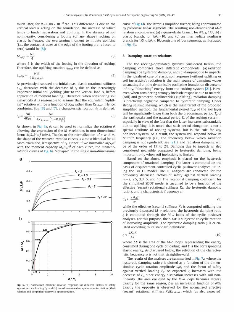
As shown in Fig. 6a, θS can be used to normalize the rotation θ,allowing the expression of the M–θ relations in non-dimensionalform: M/SuB3¼ f (θ/θS). Thanks to the normalization of θ with θS,the shape of the moment–rotation curves is almost identical for allcases examined, irrespective of FS. Hence, if we normalize M/SuB3
with the moment capacity Mu/SuB3 of each curve, the moment–rotation curves of Fig. 6a “collapse” in the single non-dimensional
curve of Fig. 6b. The latter is simplified further, being approximatedby piecewise linear segments. The resulting non-dimensional M–θrelation encompasses: (a) a quasi-elastic branch, for θ/θsr1/3; (b) aplastic branch, for θ/θs410; and (c) an intermediate nonlinearbranch, for 1/3oθ/θsr10, consisting of four segments, as illustratedin Fig. 6b.
5. Damping–rotation relations
For the rocking-dominated systems considered herein, thedamping comprises three different components: (a) radiationdamping, (b) hysteretic damping, and (c) damping due to impacts.In the idealized case of elastic soil response (without uplifting orsoil inelasticity), radiation is the main source of damping: wavesemanating from the dynamically oscillating foundation disperse toinfinity, “absorbing” energy from the rocking system [21]. How-ever, when considering strongly inelastic response due to material(soil) and geometric nonlinearities (uplifting), radiation dampingis practically negligible compared to hysteretic damping. Understrong seismic shaking, which is the main target of the proposedsimplified method, the fundamental period Tsoil of the soil layerwill be significantly lower than both the predominant period Tp ofthe earthquake and the natural period Tn of the rocking system –
especially in view of the fact that the latter increases substantiallydue to uplifting. It is noted that such period elongation is not aspecial attribute of rocking systems, but is the rule for anynonlinear system. As a result, the system will respond below its“cutoff” frequency (i.e., the frequency below which radiationdamping is not significant, see [21]), and radiation damping willbe of the order of 1% to 2%. Damping due to impacts is alsoconsidered negligible compared to hysteretic damping, beingimportant only when soil inelasticity is limited.
Based on the above, emphasis is placed on the hystereticcomponent of rotational damping. The latter is computed on thebasis of displacement-controlled cyclic pushover analyses, utiliz-ing the 3D FE model. The FE analyses are conducted for thepreviously discussed factors of safety against vertical loadingFS¼2, 2.5, 3.3, 5, and 10. The rotational damping coefficient forthe simplified SDOF model is assumed to be a function of theeffective (secant) rotational stiffness KR, the hysteretic dampingratio ξ, and a characteristic frequency ω:
CR �2 KRξ
ωð9Þ
while the effective (secant) stiffness KR is computed utilizing thepreviously discussed M–θ relations, the hysteretic damping ratioξ is computed through the M–θ loops of the cyclic pushoveranalyses. For this purpose, the SDOF is subjected to cyclic rotationof increasing amplitude. The hysteretic damping ratio ξ is calcu-lated according to its standard definition:
ξ� ΔΕ=Ε4π
ð10Þ
where ΔΕ is the area of the M–θ loops, representing the energyconsumed during one cycle of loading, and E is the correspondingelastic energy. As discussed below, the selection of the character-istic frequency ω is not that straightforward.
The results of the analyses are summarized in Fig. 7a, where thehysteretic damping ratio ξ is plotted as a function of the dimen-sionless cyclic rotation amplitude θ/θS and the factor of safetyagainst vertical loading FS. As expected, ξ increases with thedecrease of FS, since energy dissipation increases with soil non-linearity (the area enclosed by the M–θ loops becomes larger).Exactly for the same reason, ξ is an increasing function of θ/θS.Exactly the opposite is observed for the normalized effective(secant) rotational stiffness KR/KR,elastic, which (as also expected)
Fig. 6. (a) Normalized moment–rotation response for different factors of safetyagainst vertical loading FS; and (b) non-dimensional unique moment–rotation (M–θ)relation and simplified piecewise approximation.
I. Anastasopoulos, Th. Kontoroupi / Soil Dynamics and Earthquake Engineering 56 (2014) 28–43 33
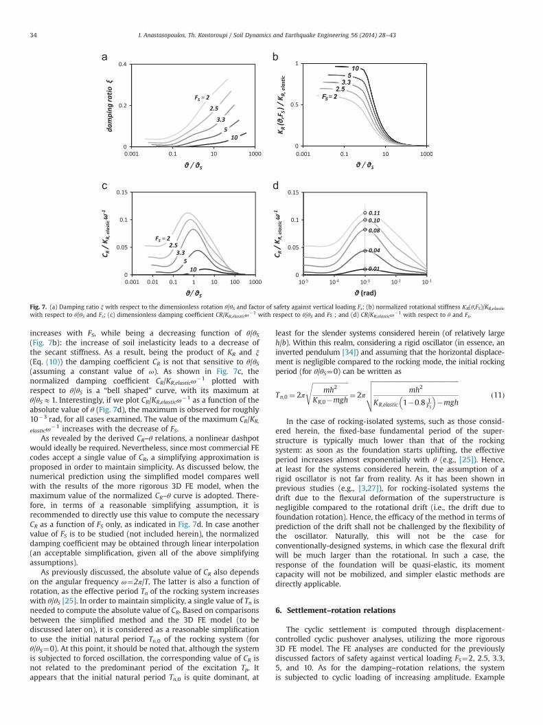
increases with FS, while being a decreasing function of θ/θS(Fig. 7b): the increase of soil inelasticity leads to a decrease ofthe secant stiffness. As a result, being the product of KR and ξ(Eq. (10)) the damping coefficient CR is not that sensitive to θ/θS(assuming a constant value of ω). As shown in Fig. 7c, thenormalized damping coefficient CR/KR,elasticω
�1 plotted withrespect to θ/θS is a “bell shaped” curve, with its maximum atθ/θSE1. Interestingly, if we plot CR/KR,elasticω
�1 as a function of theabsolute value of θ (Fig. 7d), the maximum is observed for roughly10�3 rad, for all cases examined. The value of the maximum CR/KR,
elasticω�1 increases with the decrease of FS.
As revealed by the derived CR–θ relations, a nonlinear dashpotwould ideally be required. Nevertheless, since most commercial FEcodes accept a single value of CR, a simplifying approximation isproposed in order to maintain simplicity. As discussed below, thenumerical prediction using the simplified model compares wellwith the results of the more rigorous 3D FE model, when themaximum value of the normalized CR–θ curve is adopted. There-fore, in terms of a reasonable simplifying assumption, it isrecommended to directly use this value to compute the necessaryCR as a function of FS only, as indicated in Fig. 7d. In case anothervalue of FS is to be studied (not included herein), the normalizeddamping coefficient may be obtained through linear interpolation(an acceptable simplification, given all of the above simplifyingassumptions).
As previously discussed, the absolute value of CR also dependson the angular frequency ω¼2π/T. The latter is also a function ofrotation, as the effective period Tn of the rocking system increaseswith θ/θS [25]. In order to maintain simplicity, a single value of Tn isneeded to compute the absolute value of CR. Based on comparisonsbetween the simplified method and the 3D FE model (to bediscussed later on), it is considered as a reasonable simplificationto use the initial natural period Tn,0 of the rocking system (forθ/θS¼0). At this point, it should be noted that, although the systemis subjected to forced oscillation, the corresponding value of CR isnot related to the predominant period of the excitation Tp. Itappears that the initial natural period Tn,0 is quite dominant, at
least for the slender systems considered herein (of relatively largeh/b). Within this realm, considering a rigid oscillator (in essence, aninverted pendulum [34]) and assuming that the horizontal displace-ment is negligible compared to the rocking mode, the initial rockingperiod (for θ/θS¼0) can be written as
Tn;0 ¼ 2π
ffiffiffiffiffiffiffiffiffiffiffiffiffiffiffiffiffiffiffiffiffiffiffimh2
KR;0�mgh
s¼ 2π
ffiffiffiffiffiffiffiffiffiffiffiffiffiffiffiffiffiffiffiffiffiffiffiffiffiffiffiffiffiffiffiffiffiffiffiffiffiffiffiffiffiffiffiffiffiffiffiffiffiffiffiffiffiffimh2
KR;elastic 1�0:8 1FS
� ��mgh
vuuut ð11Þ
In the case of rocking-isolated systems, such as those consid-ered herein, the fixed-base fundamental period of the super-structure is typically much lower than that of the rockingsystem: as soon as the foundation starts uplifting, the effectiveperiod increases almost exponentially with θ (e.g., [25]). Hence,at least for the systems considered herein, the assumption of arigid oscillator is not far from reality. As it has been shown inprevious studies (e.g., [3,27]), for rocking-isolated systems thedrift due to the flexural deformation of the superstructure isnegligible compared to the rotational drift (i.e., the drift due tofoundation rotation). Hence, the efficacy of the method in terms ofprediction of the drift shall not be challenged by the flexibility ofthe oscillator. Naturally, this will not be the case forconventionally-designed systems, in which case the flexural driftwill be much larger than the rotational. In such a case, theresponse of the foundation will be quasi-elastic, its momentcapacity will not be mobilized, and simpler elastic methods aredirectly applicable.
6. Settlement–rotation relations
The cyclic settlement is computed through displacement-controlled cyclic pushover analyses, utilizing the more rigorous3D FE model. The FE analyses are conducted for the previouslydiscussed factors of safety against vertical loading FS¼2, 2.5, 3.3,5, and 10. As for the damping–rotation relations, the systemis subjected to cyclic loading of increasing amplitude. Example
Fig. 7. (a) Damping ratio ξ with respect to the dimensionless rotation θ/θS and factor of safety against vertical loading Fs; (b) normalized rotational stiffness ΚR(θ,FS)/KR,elastic
with respect to θ/θS and Fs; (c) dimensionless damping coefficient CR/KR,elasticω�1 with respect to θ/θS and Fs ; and (d) CR/KR,elasticω
�1 with respect to θ and Fs.
I. Anastasopoulos, Th. Kontoroupi / Soil Dynamics and Earthquake Engineering 56 (2014) 28–4334
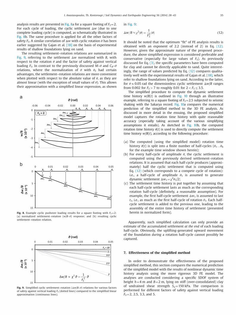
analysis results are presented in Fig. 8a for a square footing of FS¼2.For each cycle of loading, the cyclic settlement Δw (due to onecomplete loading cycle) is computed, as schematically illustrated inFig. 8b. The same procedure is applied for all the other factors ofsafety FS. A similar correlation of Δw with cyclic rotation θ has beenearlier suggested by Gajan et al. [18] on the basis of experimentalresults of shallow foundations lying on sand.
The resulting settlement–rotation relations are summarized inFig. 9, referring to the settlement Δw normalized with B, withrespect to the rotation θ and the factor of safety against verticalloading FS. In contrast to the previously discussed M–θ and CR–θrelations, where the normalization of θ with θS had certainadvantages, the settlement–rotation relations are more convenientwhen plotted with respect to the absolute value of θ, as they arealmost linear (with the exception of small values of θ). This allowstheir approximation with a simplified linear expression, as shown
in Fig. 9:
Δw=B� χ2jθj ¼ 1
F2Sθjj ð12Þ
It should be noted that the optimum “fit” of FE analysis results isobtained with an exponent of 2.2 (instead of 2) in Eq. (12).However, given the approximate nature of the proposed proce-dure, the above simplified expression is considered preferable andconservative (especially for large values of FS). As previouslydiscussed for Eq. (3), the specific parameters have been computedfor clay and cannot be directly applicable to sand. Quite interest-ingly, the range of values predicted by Eq. (12) compares qualita-tively well with the experimental results of Gajan et al. [18], whichrefer to shallow foundations lying on sand. According to the latter,for θE0.05 rad the dimensionless cyclic settlement Δw/B rangesfrom 0.002 for FS47 to roughly 0.01 for 2oFSr3.5.
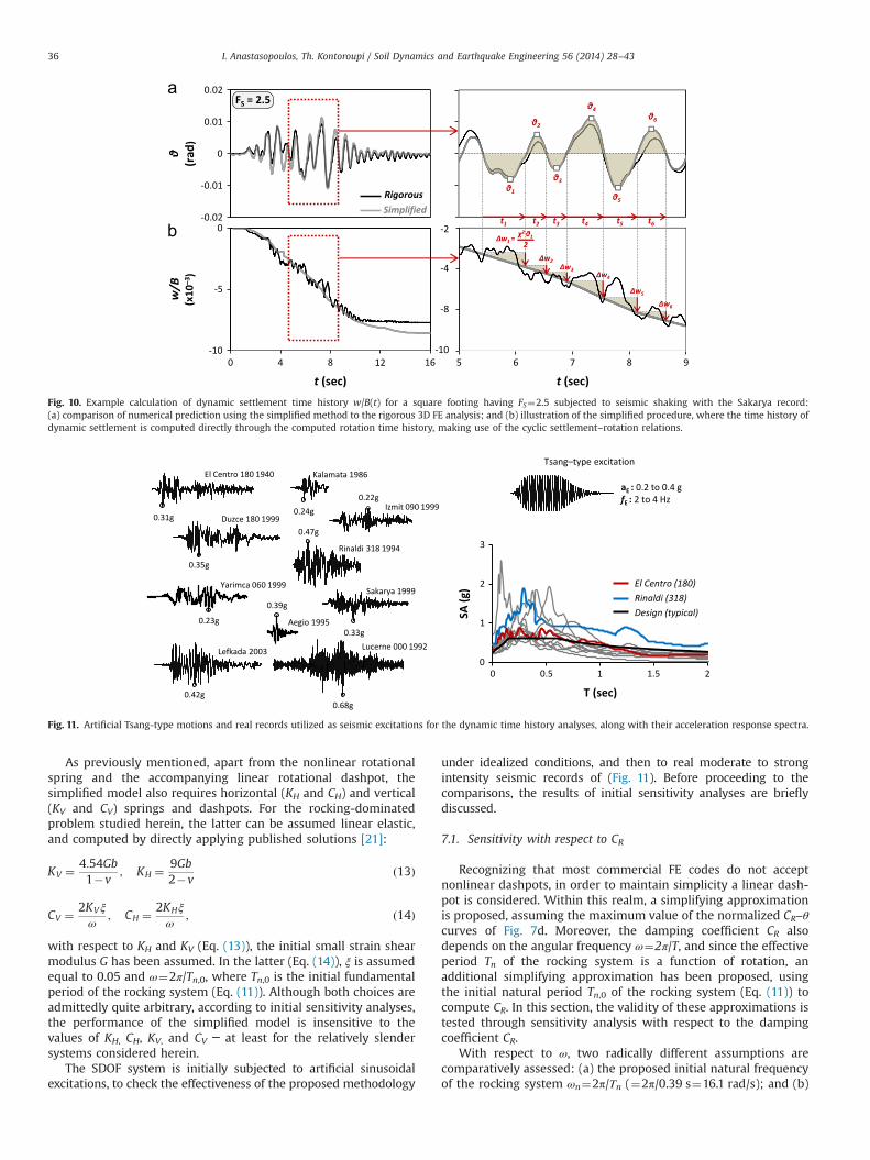
The simplified procedure to compute the dynamic settlementtime history w/B(t) is outlined in Fig. 10 through an illustrativeexample, referring to a square footing of FS¼2.5 subjected to seismicshaking with the Sakarya record. Fig. 10a compares the numericalprediction of the simplified method to the 3D FE analysis. Asdiscussed in more detail in the ensuing, the proposed simplifiedmodel captures the rotation time history with quite reasonableaccuracy (especially taking account of the various simplifyingassumptions it entails). As sketched in Fig. 10b, the computedrotation time history θ(t) is used to directly compute the settlementtime history w/B(t), according to the following procedure:
(a) The computed (using the simplified model) rotation timehistory θ(t) is split into a finite number of half-cycles (θ1…θ6for the example time window shown herein);
(b) For every half-cycle of amplitude θ, the cyclic settlement iscomputed using the previously derived settlement–rotationrelations. It is assumed that each half-cycle produces (approxi-mately) half the cyclic settlement that is computed usingEq. (12) (which corresponds to a compete cycle of rotation):i.e., a half-cycle of amplitude θ1 is assumed to generatedynamic settlement Δw1¼χ2θ1/2;
(c) The settlement time history is put together by assuming thateach half-cycle settlement lasts as much as the correspondingrotation half-cycle (definitely, a reasonable assumption). Forexample, the first half-cycle settlement Δw1 is assumed to lastt1, i.e., as much as the first half-cycle of rotation θ1. Each half-cycle settlement is added to the previous one, leading to theassembly of the entire time history of settlement (presentedherein in normalized form).
Apparently, such simplified calculation can only provide anestimate of the accumulated settlement at the end of each loadinghalf-cycle. Obviously, the uplifting-generated upward movementof the foundation during a rotation half-cycle cannot possibly becaptured.
7. Effectiveness of the simplified method
In order to demonstrate the effectiveness of the proposedsimplified method, this section compares the numerical predictionof the simplified model with the results of nonlinear dynamic timehistory analysis using the more rigorous 3D FE model. Theanalyses are conducted considering a specific SDOF system ofheight h¼4 m and B¼2 m, lying on stiff (over-consolidated) clayof undrained shear strength Su¼150 kPa. The comparison isperformed for different factors of safety against vertical loadingFS¼2, 2.5, 3.3, and 5.
Fig. 8. Example cyclic pushover loading results for a square footing with FS¼2:(a) normalized settlement–rotation (w/B–θ) response; and (b) resulting cyclicsettlement–rotation relation.
Fig. 9. Simplified cyclic settlement–rotation (Δw/B–θ) relations for various factorsof safety against vertical loading FS (dotted lines) compared to the simplified linearapproximation (continuous lines).
I. Anastasopoulos, Th. Kontoroupi / Soil Dynamics and Earthquake Engineering 56 (2014) 28–43 35
As previously mentioned, apart from the nonlinear rotationalspring and the accompanying linear rotational dashpot, thesimplified model also requires horizontal (KH and CH) and vertical(KV and CV) springs and dashpots. For the rocking-dominatedproblem studied herein, the latter can be assumed linear elastic,and computed by directly applying published solutions [21]:
KV ¼ 4:54Gb1�v
; KH ¼ 9Gb2�v
ð13Þ
CV ¼ 2KVξ
ω; CH ¼ 2KHξ
ω; ð14Þ
with respect to KH and KV (Eq. (13)), the initial small strain shearmodulus G has been assumed. In the latter (Eq. (14)), ξ is assumedequal to 0.05 and ω¼2π/Tn,0, where Tn,0 is the initial fundamentalperiod of the rocking system (Eq. (11)). Although both choices areadmittedly quite arbitrary, according to initial sensitivity analyses,the performance of the simplified model is insensitive to thevalues of KH, CH, KV, and CV ─ at least for the relatively slendersystems considered herein.
The SDOF system is initially subjected to artificial sinusoidalexcitations, to check the effectiveness of the proposed methodology
under idealized conditions, and then to real moderate to strongintensity seismic records of (Fig. 11). Before proceeding to thecomparisons, the results of initial sensitivity analyses are brieflydiscussed.
7.1. Sensitivity with respect to CR
Recognizing that most commercial FE codes do not acceptnonlinear dashpots, in order to maintain simplicity a linear dash-pot is considered. Within this realm, a simplifying approximationis proposed, assuming the maximum value of the normalized CR–θcurves of Fig. 7d. Moreover, the damping coefficient CR alsodepends on the angular frequency ω¼2π/T, and since the effectiveperiod Tn of the rocking system is a function of rotation, anadditional simplifying approximation has been proposed, usingthe initial natural period Tn,0 of the rocking system (Eq. (11)) tocompute CR. In this section, the validity of these approximations istested through sensitivity analysis with respect to the dampingcoefficient CR.
With respect to ω, two radically different assumptions arecomparatively assessed: (a) the proposed initial natural frequencyof the rocking system ωn¼2π/Τn (¼2π/0.39 s¼16.1 rad/s); and (b)
Fig. 10. Example calculation of dynamic settlement time history w/B(t) for a square footing having FS¼2.5 subjected to seismic shaking with the Sakarya record:(a) comparison of numerical prediction using the simplified method to the rigorous 3D FE analysis; and (b) illustration of the simplified procedure, where the time history ofdynamic settlement is computed directly through the computed rotation time history, making use of the cyclic settlement–rotation relations.
Fig. 11. Artificial Tsang-type motions and real records utilized as seismic excitations for the dynamic time history analyses, along with their acceleration response spectra.
I. Anastasopoulos, Th. Kontoroupi / Soil Dynamics and Earthquake Engineering 56 (2014) 28–4336
the predominant frequency of the seismic excitation ωp¼2π/Τp.To make a strong point, the Lucerne(000) record from the 1992 MS
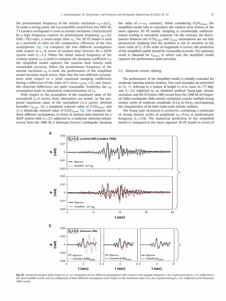
7.3 Landers earthquake is used as seismic excitation. Characterizedby a high frequency content, its predominant frequency ωp¼2π/0.08¼78.5 rad/s, is much larger than ωn. The 3D FE model is usedas a yardstick to infer on the comparative efficiency of the twoassumptions. Fig. 12a compares the two different assumptionswith respect to ω, in terms of rotation time histories for a SDOFsystem with FS¼3.3. When the initial natural frequency of therocking system ωn is used to compute the damping coefficient CR,the simplified model captures the rotation time history withremarkable accuracy. When the predominant frequency of theseismic excitation ωp is used, the performance of the simplifiedmodel becomes much worse. Note that the two different assump-tions with respect to ω yield rotational damping coefficientshaving a difference of the order of 5 (since ωp/ωnE5), and, hence,the observed differences are quite reasonable. Evidently, the ωp
assumption leads to substantial underestimation of CR.With respect to the assumption of the maximum value of the
normalized CR–θ curves, three alternatives are tested: (a) the pro-posed maximum value of the normalized CR–θ curves, denotedhereafter CR,max; (b) a somehow reduced value of 0.75CR,max; and(c) a drastically reduced value of 0.25CR,max. Fig. 12b compares thethree different assumptions, in terms of rotation time histories for aSDOF system with FS¼2.5 subjected to a moderate intensity seismicrecord, from the 1986 MS 6 Kalamata (Greece) earthquake (keeping
the value of ω¼ωn constant). When considering 0.25CR,max, thesimplified model fails to reproduce the rotation time history of themore rigorous 3D FE model: damping is considerably underesti-mated, leading to unrealistic response. On the contrary, the discre-pancies between the 0.75CR,max and CR,max assumptions are not thatpronounced, implying that the problem is not so sensitive to theexact value of CR: if the order of magnitude is correct, the predictionof the simplified model should be reasonably accurate. The optimumresult is obtained for CR,max, in which case the simplified modelcaptures the performance quite precisely.
7.2. Moderate seismic shaking
The performance of the simplified model is initially evaluated formoderate intensity seismic motions. Two such examples are presentedin Fig. 13, referring to a system of height h¼4m, mass m¼75 Mgr,and Fs¼2.5 subjected to an idealized artificial Tsang-type seismicexcitation, and the El Centro (180) record from the 1940MS 6.9 Imper-ial Valley earthquake. Both seismic excitations contain multiple strongmotion cycles of moderate amplitude (0.3 g to 0.4 g), encompassingthe characteristics of far-field multi-cycle seismic motions.
The Tsang-type excitation is symmetric, containing a multitudeof strong motion cycles of amplitude aΕ¼0.4 g at predominantfrequency fΕ¼2 Hz. The numerical prediction of the simplifiedmodel is compared to the more rigorous 3D FE model in terms of
-0.02
-0.01
0
0.01
0.02
0 6 12 18 24
Rigorous
Simplified : ω = ωp
-0.02
-0.01
0
0.01
0.02Lucerne 000 (Landers 1992)
Rigorous
Simplified : ω = ωn
0 4 8
t (sec)0 4 8
t (sec)
-0.04
-0.02
0
0.02
0.04
0 4 8
t (sec)
(Kalamata 1986)
Rigorous Simplified: 0.25CR,max
Rigorous Simplified:0.75CR,max
Rigorous Simplified:CR,max
FS= 3.3
FS= 2.5
t (sec)
(rad
)(r
ad)
(rad
)
Fig. 12. Sensitivity analysis with respect to CR: (a) comparison of two different assumptions with respect to the angular frequency ω for a system having FS¼3.3, subjected tothe Lucerne(000) record; and (b) comparison of three different assumptions with respect to the maximum value of CR for a system having FS¼2.5, subjected to the Kalamata1986 record.
I. Anastasopoulos, Th. Kontoroupi / Soil Dynamics and Earthquake Engineering 56 (2014) 28–43 37
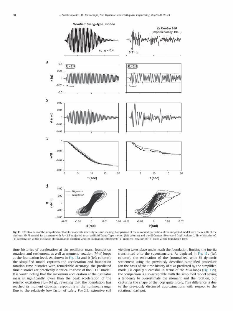
time histories of acceleration at the oscillator mass, foundationrotation, and settlement, as well as moment–rotation (M–θ) loopsat the foundation level. As shown in Fig. 13a and b (left column),the simplified model captures the acceleration and foundationrotation time histories with remarkable accuracy: the predictedtime histories are practically identical to those of the 3D FE model.It is worth noting that the maximum acceleration at the oscillatormass is significantly lower than the peak acceleration of theseismic excitation (aΕ¼0.4 g), revealing that the foundation hasreached its moment capacity, responding in the nonlinear range.Due to the relatively low factor of safety FS¼2.5, extensive soil
yielding takes place underneath the foundation, limiting the inertiatransmitted onto the superstructure. As depicted in Fig. 13c (leftcolumn), the estimation of the (normalized with B) dynamicsettlement using the previously described simplified procedure(on the basis of the time history of θ, as predicted by the simplifiedmodel) is equally successful. In terms of the M–θ loops (Fig. 13d),the comparison is also acceptable, with the simplified model havinga tendency to overestimate the moment and the rotation, butcapturing the shape of the loop quite nicely. This difference is dueto the previously discussed approximations with respect to therotational dashpot.
0 5 10 15 20
El Centro 180(Imperial Valley,1940)
0.31 g
0 5 10 15 20
Modified Tsang–type motion
aE : g = 0.4 a
(g)
acut–off acut–off
-0.02
-0.01
0
0.01
20
t (sec) 5 10 15 20
-0.03
-0.02
-0.01
0
0 5 10 15 20
t (sec)
w/B
-1400
-700
0
700
1400
-0.02 -0.01 0 00.01 0.02
RigorousSimplified
M(k
Nm
)
-0.02 -0.01 0.01 0.02
FS= 2.5 FS= 2.5
-0.5
-0.25
0
0.25
20
(rad
)
(rad) (rad)
0.02
0.5
Fig. 13. Effectiveness of the simplified method for moderate intensity seismic shaking. Comparison of the numerical prediction of the simplified model with the results of therigorous 3D FE model, for a system with FS¼2.5 subjected to an artificial Tsang-Type motion (left column) and the El Centro(180) record (right column). Time histories of:(a) acceleration at the oscillator, (b) foundation rotation, and (c) foundation settlement; (d) moment–rotation (M–θ) loops at the foundation level.
I. Anastasopoulos, Th. Kontoroupi / Soil Dynamics and Earthquake Engineering 56 (2014) 28–4338
The El Centro (180) record is selected for two reasons: (i) havinga PGA¼0.31 g, and containing a multitude of strong motion cyclesof various frequencies, it may be considered representative of atypical design earthquake, at least in terms of spectral acceleration(see Fig. 11); and (ii) being a far-field record, it is not affected byforward-rupture directivity effects, which tend to complicate theresponse of strongly nonlinear systems, such as the one investi-gated herein. As shown in Fig. 13a–c (right column), the simplifiedmodel captures the acceleration, rotation, and settlement timehistories quite nicely. The latter cannot possibly be reproduced indetail, as the simplified procedure does not account for the upliftingduring each half-cycle of loading. Finally, the comparison is alsoquite successful in terms of M–θ loops (Fig. 13d). Observe that the
real record, despite having a lower PGA (0.31 g as opposed to 0.4 gof the Tsang-type motion), leads to the development of largerfoundation rotation θ and increased soil inelasticity. On the otherhand, due to its multitude of strong motion cycles (of constantamplitude aΕ¼0.4 g), the Tsang-type excitation produces substan-tially larger dynamic settlement.
7.3. Strong seismic shaking
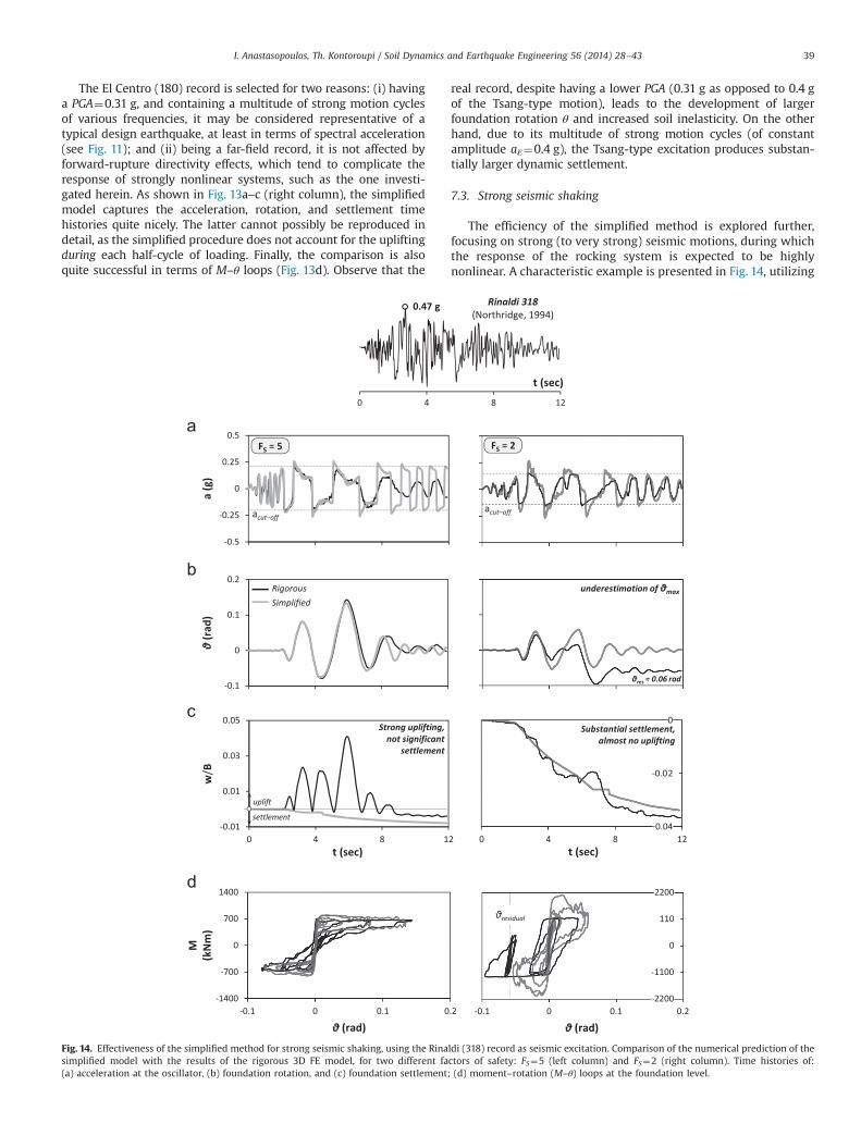
The efficiency of the simplified method is explored further,focusing on strong (to very strong) seismic motions, during whichthe response of the rocking system is expected to be highlynonlinear. A characteristic example is presented in Fig. 14, utilizing
Fig. 14. Effectiveness of the simplified method for strong seismic shaking, using the Rinaldi (318) record as seismic excitation. Comparison of the numerical prediction of thesimplified model with the results of the rigorous 3D FE model, for two different factors of safety: FS¼5 (left column) and FS¼2 (right column). Time histories of:(a) acceleration at the oscillator, (b) foundation rotation, and (c) foundation settlement; (d) moment–rotation (M–θ) loops at the foundation level.
I. Anastasopoulos, Th. Kontoroupi / Soil Dynamics and Earthquake Engineering 56 (2014) 28–43 39
the Rinaldi (318) record from the 1994 MS 7.2 Northridge asseismic excitation. The latter is a particularly destructive near-field record, encompassing the effects of forward-rupture direc-tivity. Two different factors of safety are investigated, one beingrepresentative of (relatively) lightly-loaded systems, FS¼5 (leftcolumn), and the other referring to more heavily-loaded systems,FS¼2 (right column).
As evidenced by the acceleration time histories of Fig. 14a, theRinaldi record is, indeed, quite extreme for the lightly-loaded FS¼5system. Observe the acceleration cut-off at roughly 0.24 g (corre-sponding to the critical acceleration of the rocking system), whichis repeatedly of particularly long-duration. During each accelera-tion “plateau”, the foundation reaches its moment capacity,exhibiting strongly-nonlinear response. Limiting the inertia trans-mitted to the superstructure, this acceleration cut-off is obviouslyadvantageous. As a result, however, the system is forced toexcessively large rotations of the order of 0.1 rad (Fig. 14b) –
almost an order of magnitude larger compared to the previouscases. The simplified model captures correctly the accelerationcut-off, being less accurate in terms of the details of the accelera-tion time history. Interestingly, despite these discrepancies, therotation time history is predicted with impressive accuracy (minordiscrepancies can be observed only towards the end). Althoughthe footing develops large rotations, the residual rotation at theend of shaking is practically negligible: an inherent self-centeringattribute of rocking systems, provided that the factor of safetyagainst vertical loading is adequately large (FsZ5 for clay), so as toensure uplifting-dominated response. As shown in Fig. 14c, the
residual settlement is slightly overestimated, being, however,almost negligible thanks to the uplifting-dominated response ofthe system. As previously discussed, the simplified approximatesettlement–rotation relations of Eq. (12) are conservative, espe-cially for large Fs (see Fig. 9). Hence, this difference is quite natural.Moreover, the upward displacement due to uplifting cannotpossibly be captured by the simplified method. Finally, thecomparison is excellent in terms of moment–rotation (M–θ) loops(Fig. 14d).
In the case of the heavily-loaded FS¼2 system (right column ofFig. 14), the discrepancies between the simplified and the 3D FEmodel are far more pronounced. Although the simplified modeldoes capture the moment capacity of the system, as evidenced bythe acceleration cut-off in Fig. 14b, due to the very low FS excessiveplastic deformation takes place during strong seismic shakingleading to the development of very large irrecoverable rotations(Fig. 14b). As a result, the residual rotation θresE0.06 rad is not atall negligible, and cannot possibly be captured by the simplifiedmodel. Quite surprisingly, the total prediction of the dynamicsettlement is satisfactory (Fig. 14c). Although this might seem as aparadox, it is quite easily explainable. With the exception ofrotation accumulation, the rotation time history is not poorlypredicted, at least with respect to the amplitude of individualrotation half-cycles. Consequently, there is no reason for thesettlement not to be predicted correctly. The M–θ loops ofFig. 14d confirm the yielding-dominated behavior of the system,and the (natural and expected) inability of the simplified model tocapture the residual rotation. Most importantly, in this case the
θresidual
-0.04
-0.02
0
0.02
0.04RigorousSimplified
-0.03
-0.02
-0.01
0
0 5 10 15 20
t (sec)
limited soil plastification
extensive soil plastification
-0.005
0
0.005
0.01
0 5 10 15 20
uplift
settlement
strong uplifting, not significant settlement
t (sec)
w/B
θmax
FS= 5 FS= 2
(rad
)
Fig. 15. Effectiveness of the simplified method for strong seismic shaking, using the Yarimca (060) record as seismic excitation. Comparison of the numerical prediction ofthe simplified model with the results of the rigorous 3D FE model, for two different factors of safety: FS¼5 (let column) and FS¼2 (right column): (a) deformed mesh withplastic strain contours (rigorous model); time histories of (b) foundation rotation, and (c) settlement.
I. Anastasopoulos, Th. Kontoroupi / Soil Dynamics and Earthquake Engineering 56 (2014) 28–4340
simplified model substantially overestimates the developingmoment. This is directly related to the linear dashpot, which isconnected in parallel with the nonlinear rotational spring. It is aclear shortcoming of the simplified method, which is, however, ofimportance for low factors of safety FS combined with very strongdirectivity-affected seismic excitations. In such cases, the simpli-fied model should be used with caution, as the error in predictingthe inertia loading of the system can be quite substantial. Theproblem can be solved by connecting the spring in series, asdescribed by Wang et al. [60].
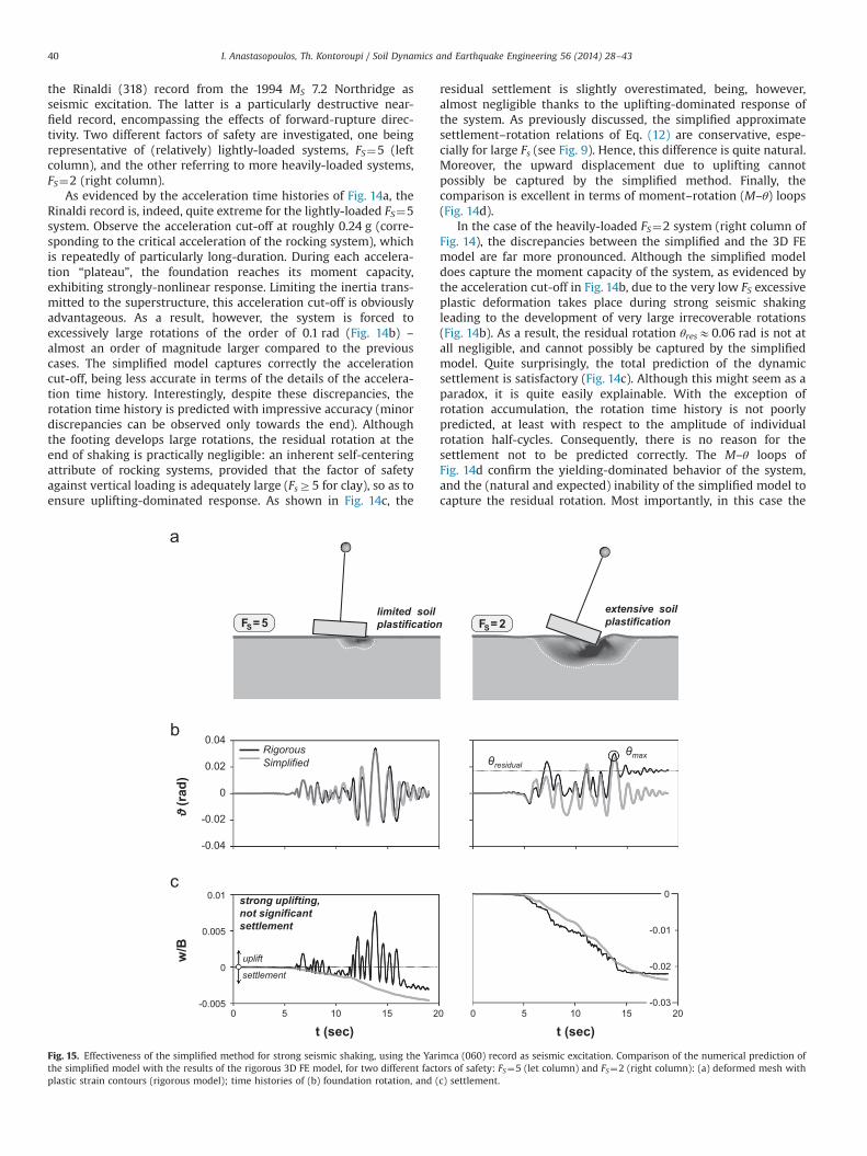
It should be emphasized, however, that the previous example isactually a worst-case scenario, not being representative of theoverall performance of the simplified method. In general, even forvery low FS and seismic motions containing strong directivitypulses, its performance is on average quite acceptable. Actually, inthe majority of the cases examined the accumulation of residualrotation does not seem to affect the estimation of maximumrotation, which is of prime significance for design purposes. Onesuch example is given in Fig. 15, referring to the same factors ofsafety (FS¼5 and 2), but using as seismic excitation the Yarimca(060) record from the 1999 MS 7.4 Kocaeli earthquake. The twosnapshots of deformed mesh with superimposed plastic straincontours (computed with the more rigorous 3D FE model) at theend of seismic shaking (Fig. 15a) show vividly the fundamentaldifference in the response of the two systems. While for FS¼5 thebehavior is clearly uplifting-dominated, with plastic deformationbeing localized within a very narrow zone underneath the foun-dation, the performance of the FS¼2 system is characterized byextensive soil plastification. As expected, for the lightly-loaded(FS¼5) system the simplified method predicts the time history ofrotation quite accurately (Fig. 15b). But even for the heavily-loaded(FS¼2) system, although the rotation time histories do not
perfectly match (due to the unavoidable accumulation of rotation),the maximum value of θ is predicted quite successfully. As for theprevious example, the simplified method captures the settlementwith remarkable accuracy (Fig. 15c). Despite the above mentionedproblems, the simplified method seems to perform better for theheavily-loaded system, overestimating the settlement of thelightly-loaded one. This is directly associated to the conservatismof the proposed Δw–θ relations (see Eq. (12)).
8. Synopsis and conclusions
This paper has introduced a simplified method to analyze theseismic performance of rocking systems, taking account of soilinelasticity and foundation uplifting. The soil–foundation system isreplaced by springs and dashpots. While the horizontal (KH and CH)and vertical (KV and CV) springs and dashpots are assumed elastic,directly obtained by published solutions [21], for the rotationaldegree of freedom a nonlinear rotational spring is employed,accompanied by a linear dashpot. Three relations are required, allof them being a function of the factor of safety against verticalloading FS: (a) the moment–rotation (M–θ) relation, (b) the dampingcoefficient–rotation (CR–θ) relation, and (c) the dynamic settle-ment–rotation (Δwdyn–θ) relation. Focusing on square shallowfoundations, the necessary relations are computed through 3D FEanalyses, applying a thoroughly validated constitutive model [4].
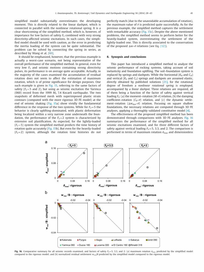
The effectiveness of the proposed simplified method has beendemonstrated through comparisons with 3D FE analyses. Fig. 16summarizes the performance of the simplified method for allseismic excitations examined, and for three different factors ofsafety against vertical loading FS¼5, 3.3, and 2. The comparison isperformed in terms of maximum rotation θmax and dimensionless
0
0.08
0 0.08 0.160
0 0.08 0.160
0.08
0.16
0 0.08 0.16
max
: sim
plifi
ed
-0.04
-0.02
0-0.04-0.020
-0.02
0-0.04-0.020
-0.04
-0.02
0-0.04-0.020
Kalamata Pyrgos Aegio Lefkada Sakarya Izmit 090
Yarimca 060 Duzce 180 Lucerne 000 El Centro 180 Rinaldi 318
FS= 5 FS= 3.3 FS= 2
wres /B : rigorous wres /B : rigorous wres /B : rigorous
wre
s/B
: si
mpl
ified
max : rigorous max : rigorous max : rigorous
Fig. 16. Comparative summary for all seismic records examined, and factors of safety FS¼5, 3.3, and 2: (a) maximum rotation θmax predicted by the simplified modelcompared to the rigorous model; and (b) normalized residual settlement wres/B predicted by the simplified model compared to the rigorous model.
I. Anastasopoulos, Th. Kontoroupi / Soil Dynamics and Earthquake Engineering 56 (2014) 28–43 41
residual settlement wres/B, plotting the prediction of the simplifiedmodel (vertical axis) against the corresponding results of therigorous 3D FE model (horizontal axis). At least for the casesexamined, the effectiveness of the simplified method is fullyconfirmed. In terms of θmax (Fig. 16a), its effectiveness is quiteimpressive for all factors of safety. The only substantial discre-pancy is observed for the heavily-loaded (FS¼2) system subjectedto the directivity-affected Rinaldi record. This is related to theinability of the simplified model to capture residual rotations – anunavoidable shortcoming, which is, however, of importancemainly for (unrealistically) low FS combined with very strongseismic shaking with directivity-affected seismic excitations. Theresidual settlement is accurately predicted for all cases examined(Fig. 16b).
Although the proposed simplified method is based on severalsimplifying approximations (some of them being, admittedly, quitecrude), it is considered as a valid alternative for the preliminarydesign of rocking-isolated systems. Being easily implementable incommercial FE codes, without requiring calibration of sophisticatedmodels and avoiding the need for time consuming 3D FE analyses,it has the potential of being applied in practice in the near future.The proposed procedure is simple and straightforward, not requiringiterations to compute the response. Although this paper has focusedon square foundations, the same methodology can be employed forother footing shapes (rectangular, circular, strip), or for embeddedfoundations. Alternatively, the required relations can be producedexperimentally, on the basis of cyclic pushover tests (e.g., [40,18,5,6]).Hence, the practicing engineer may directly apply the proposedmethodology utilizing the provided FE-derived relations, or selectfrom the literature other relations that may be considered moreappropriate.
Acknowledgment
The financial support for this paper has been provided underthe research project “DARE”, which is funded through the EuropeanResearch Council's (ERC) “IDEAS” Programme, in Support ofFrontier Research-Advanced Grant, under contract/number ERC-2-9-AdG228254-DARE to Prof. G. Gazetas.
References
[1] Allotey N, El Naggar MH. An investigation into the Winkler modeling of thecyclic response of rigid footings. Soil Dynamics and Earthquake Engineering2007;28:44–57.
[2] Anastasopoulos Ι. Beyond conventional capacity design: towards a new designphilosophy. In: Orense RP, Chouw N, Pender MJ, editors. Soil–Foundation–Structure Interaction. New York: CRC Press, Taylor & Francis Group; 2010.
[3] Anastasopoulos I, Gazetas G, Loli M, Apostolou M, Gerolymos N. Soil failurecan be used for seismic protection of structures. Bulletin of EarthquakeEngineering 2010;8:309–26.
[4] Anastasopoulos I, Gelagoti F, Kourkoulis R, Gazetas G. Simplified Constitutivemodel for simulation of cyclic response of shallow foundations: validationagainst laboratory tests. Journal of Geotechnical and GeoenvironmentalEngineering, ASCE 2011;137(12)1154–68.
[5] Anastasopoulos I, Kourkoulis R, Gelagoti F, Papadopoulos E. Metaplasticrocking response of SDOF systems on shallow improved sand: an experi-mental study. Soil Dynamics and Earthquake Engineering 2012;40:15–33.
[6] Anastasopoulos I, Loli M, Gelagoti F, Kourkoulis R, Gazetas G. Nonlinear soil–foundation interaction: numerical analysis. In: Proceedings of the 2nd inter-national conference on performance-based design in earthquake geotechnicalengineering. Taormina, Italy, May 28–30; 2012b.
[7] Anastasopoulos I, Gelagoti F, Spyridaki A, Sideri Tz, Gazetas G. Seismic rockingisolation of asymmetric frame on spread footings. Journal of Geotechnical andGeoenvironmental Engineering, ASCE 2014;140(1). http://dx.doi.org/10.1061/(ASCE)GT.1943-5606.0001012.
[8] Apostolou M, Gazetas G. Analytical modelling of footings under large over-turning moment. In: Proceedings of the 2nd Japan–Greece workshop on seismicdesign, observation, retrofit of foundations. Tokyo, Japan; 2007. p. 165–184.
[9] Bienen B, Gaudin C, Cassidy MJ. Centrifuge tests of shallow footing behavior onsand under combined vertical-torsional loading. International Journal ofPhysical Modelling in Geotechnics 2007;2:1–21.
[10] Bransby MF, Randolph MF. Combined loading of skirted foundations. Géo-technique 1998;48(5):637–55.
[11] Butterfield R, Gottardi G. A complete three-dimensional failure envelope forshallow footings on sand. Géotechnique 1994;44(1):181–4.
[12] Chatzigogos CT, Pecker A, Salençon J. Macroelement modeling of shallowfoundations. Soil Dynamics and Earthquake Engineering 2009;29(5):765–81.
[13] Crémer C, Pecker A, Davenne L. Cyclic macro-element for soil–structureinteraction: material and geometrical nonlinearities. International Journalfor Numerical and Analytical methods in Geomechanics 2001;25(12):1257–84.
[14] Deng L, Kutter BL, Kunnath SK. Centrifuge modeling of bridge systemsdesigned for rocking foundations. Journal of Geotechnical and Geoenviron-mental Engineering 2012;138(3):335–44.
[15] Faccioli E, Paolucci R, Vanini M, editors. TRISEE: 3D site effects and soil–foundation interaction in earthquake and vibration risk evaluation. EuropeanCommission Publications; 1999.
[16] Figini R, Paolucci R, Chatzigogos CT. A macro‐element model for non‐linearsoil–shallow foundation–structure interaction under seismic loads: theoreticaldevelopment and experimental validation on large scale tests. EarthquakeEngineering and Structural Dynamics 2012;41:475–93.
[17] Furumura T, Takemura S, Noguchi S, Takemoto T, Maeda T, Iwai K, et al. Strongground motions from the 2011 off-the-Pacific-Coast-of-Tohoku, Japan(Mw¼9.0) earthquake obtained from a dense nationwide seismic network.Landslides 2011;8(3):333–8.
[18] Gajan S, Phalen JD, Kutter BL, Hutchinson TC, Martin G. Centrifuge modeling ofload deformation behavior of rocking shallow foundations. Soil Dynamics andEarthquake Engineering 2005;25(7–10):773–83.
[19] Gajan S, Kutter BL. Capacity, settlement and energy dissipation of shallowfootings subjected to rocking. Journal of Geotechnical and GeoenvironmentalEngineering, ASCE 2008;134(8)1129–41.
[20] Gajan S, Kutter BL. Effects of moment-to-shear ratio on combined cyclic load–displacement behavior of shallow foundations from centrifuge experiments.Journal of Geotechnical and Geoenvironmental Engineering, ASCE 2009;135(8)1044–55.
[21] Gazetas G. Analysis of machine foundation vibrations: state of the art. SoilDynamics and Earthquake Engineering 1983;2:2–42.
[22] Gazetas G. Formulas and charts for impedances of surface and embeddedfoundations. Journal of Geotechnical Engineering, ASCE 1991;117(9)1363–81.
[23] Gazetas G, Apostolou M. Nonlinear soil–structure interaction: foundationuplifting and soil yielding. In: Proceedings 3rd UJNR workshop on soil–structure interaction. Menlo Park, California, USA (CD-ROM); 2004.
[24] Gazetas G, Apostolou M, Anastasopoulos I. Seismic uplifting of foundations onsoft soil, with examples from Adapazari (Izmit 1999, Earthquake). BGAinternational conference of foundations: innovations, observations, designand practice. Scotland: University of Dundee; 2003; 37–50.
[25] Gazetas G, Anastasopoulos I, Adamidis O, Kontoroupi T. Nonlinear rocking stiffnessof foundations. Soil Dynamics and Earthquake Engineering 2013;47:83–91.
[26] Gelagoti F, Kourkoulis R, Anastasopoulos I, Gazetas G. Seismic wave propaga-tion in Alluvial Valleys: sensitivity to ground motion details and soilnonlinearity, generation of parasitic vertical component. Bulletin of theSeismological Society of America 2010;100(6):3035–54.
[27] Gelagoti F, Kourkoulis R, Anastasopoulos I, Gazetas G. Rocking isolation of lowrise frame structures founded on separate footings. Earthquake Engineeringand Structural Dynamics 2012;41:1177–97.
[28] Gelagoti F, Kourkoulis R, Anastasopoulos I, Gazetas G. Rocking-isolated framestructures: margins of safety against toppling collapse and simplified designapproach. Soil Dynamics and Earthquake Engineering 2012;32(1):87–102.
[29] Gerolymos N, Gazetas G. Seismic response of yielding pile in non-linear soil.In: Proceedings of the 1st Greece–Japan workshop on seismic design,observation, retrofit of foundations. Athens, Greece; 2005. p. 25–37.
[30] Gourvenec S. Shape effects on the capacity of rectangular footings undergeneral loading. Géotechnique 2007;57(8):637–46.
[31] Gourvenec S, Randolph MF. Effect of strength non-homogeneity on the shapeand failure envelopes for combined loading of strip and circular foundationson clay. Géotechnique 2003;53(6):527–33.
[32] Harden C, Hutchinson T. Investigation into the effects of foundation uplift onsimplified seismic design procedures. Earthquake Spectra 2006;22(3):663–92.
[33] Houlsby GT, Amorosi A, Rojas E. Elastic moduli of soils dependent on pressure:a hyperelastic formulation. Géotechnique 2005;55(5):383–92.
[34] Housner GW. The behaviour of inverted pendulum structures duringearthquake. Bulletin of the Seismological Society of America 1963;53(2):403–17.
[35] Jennings PC, Bielak J. Dynamics of building–soil interaction. Bulletin of theSeismological Society of America 1973;63(1):9–48.
[36] Kausel E, Roesset JM. Dynamic stiffness of circular foundations. Journal ofEngineering Mechanics Division, ASCE 1975771–85.
[37] Knappett JA, Haigh SK, Madabhushi SPG. Mechanisms of failure for shallowfoundations under earthquake loading. Soil Dynamics and Earthquake Engi-neering 2006;26:91–102.
[38] Kourkoulis R, Anastasopoulos I, Gelagoti F, Kokkali P. Dimensional analysis ofSDOF system rocking on inelastic soil. Journal of Earthquake Engineering2012;16:995–1022.
[39] Kourkoulis R, Gelagoti F, Anastasopoulos I. Rocking isolation of frames onisolated footings: design insights and limitations. Journal of EarthquakeEngineering 2012;16(3):374–400.
[40] Kutter BL, Martin G, Hutchinson TC, Harden C, Gajan S, Phalen JD. Status reporton study of modeling of nonlinear cyclic load–deformation behavior of
I. Anastasopoulos, Th. Kontoroupi / Soil Dynamics and Earthquake Engineering 56 (2014) 28–4342

shallow foundations. University of California, Davis, Proceedings of the PEERWorkshop; 2003.
[41] Kutter BL, Wilson DL. Physical modeling of dynamic behavior of soil–founda-tion–superstructure systems. International Journal of Physical Modeling inGeotechnics 2006;6(1):1–12.
[42] Kutter et al., Estimation of displacement demand for seismic design of bridgeswith rocking shallow foundations. In: Proceedings of the 5th Internationalconference on recent advances in geotechnical earthquqke engineering andsoil dynamics, San Diego; 2010.
[43] Le Pape Y, Sieffert JP. Application of thermodynamics to the global modelingof shallow foundations on frictional material. International Journal forNumerical and Analytical Methods in Geomechanics 2001;25:1377–408.
[44] Martin CM, Houlsby GT. Combined loading of spudcan foundations on clay:numerical modeling. Géotechnique 2001;51(8):687–99.
[45] Maugeri M, Musumeci G, Novità D, Taylor CA. Shaking table test of failure of ashallow foundation subjected to an eccentric load. Soil Dynamics and Earth-quake Engineering 2000;20(5–8):435–44.
[46] Mergos PE, Kawashima K. Rocking isolation of a typical bridge pier on spreadfoundation. Journal of Earthquake Engineering 2005;9(2):395–414.
[47] Meyerhof GG. The bearing capacity of foundations under eccentric andinclined loads. In: Proceedings of the 3rd international conference of soilmechanics and foundation engineering, Zurich, vol. 1; 1953. p. 440–445.
[48] Negro P, Paolucci R, Pedretti S, Faccioli E. Large scale soil–structure interactionexperiments on sand under cyclic load. In: Proceedings of 12th worldconference on earthquake engineering, Paper no. 1191, Auckland, NewZealand; 2000.
[49] Nova R, Montrasio L. Settlement of shallow foundations on sand. Géotechnique1991;41(2):243–56.
[50] Paolucci R. Simplified evaluation of earthquake induced permanent displacementsof shallow foundations. Journal of Earthquake Engineering 1997;1:563–79.
[51] Paolucci R, Shirato M, Yilmaz MT. Seismic behavior of shallow foundations:shaking table experiments vs. numerical modeling. Earthquake Engineering &Structural Dynamic 2008;37(4):577–95.
[52] Paolucci R, Figini R, di Prisco C, Petrini L, Vecchiotti M. Accounting fornonlinear dynamic soil–structure interaction in the displacement-basedseismic design. In: Proceedings of the 5th international conference on earth-quake geotechnical engineering. Santiago, Chile (CD-ROM); 2011.
[53] Pecker A. A seismic foundation design process, lessons learned from twomajor projects: the Vasco de Gama and the Rion Antirion bridges. ACIInternational Conference on Seismic Bridge Design and Retrofit. La Jolla,USA: University of California at San Diego; 2003.
[54] Pender M. Seismic design and performance of surface foundations. In:Proceedings of the 4th international conference on earthquake geotechnicalengineering, Thessaloniki, Greece (CD-ROM); 2007.
[55] Priestley MJN, Calvi GM, Kowalski MJ. Displacement based seismic design ofstructures. Pavia: IUSS press; 2007.
[56] Raychowdhury P, Hutchinson T. Performance evaluation of a nonlinearWinkler-based shallow foundation model using centrifuge test results. Earth-quake Engineering and Structural Dynamics 2009;38(5):679–98.
[57] Tassoulas JL. An investigation of the effect of rigid sidewalls on the response ofembedded circular foundations to obliquely-incident SV and P waves.Dynamic Soil–Structure Interaction. Rotterdam: A.A.Balkemal; 1984; 55–63.
[58] Ukritchon B, Whittle AJ, Sloan SW. Undrained limit analysis for combinedloading of strip footings on clay. Journal of Geotechnical and Geoenviron-mental Engineering, ASCE 1998;124(3)265–76.
[59] Veletsos AS, Nair VV. Seismic interaction of structures on hysteretic founda-tions. Journal of Structural Engineering, ASCE 1975;101(1)109–29.
[60] Wang S, Kutter BL, Chacko MJ, Wilson DW, Boulanger RW, Abghari A. Nonlinearseismic soil–pile structure interaction. Earthquake Spectra 1998;14(2):377–96.
[61] Wong HL, Luco JE. Tables of impedance functions for square foundations onlayered media. Soil Dynamics and Earthquake Engineering 1985;4:64–81.
I. Anastasopoulos, Th. Kontoroupi / Soil Dynamics and Earthquake Engineering 56 (2014) 28–43 43
Related Documents
![[Drum] The Best Of Modern Drummer Rock.pdf](https://static.cupdf.com/doc/110x72/577c7c9f1a28abe0549b5457/drum-the-best-of-modern-drummer-rockpdf.jpg)