Appendix O Soil and Water Management Plan

Welcome message from author
This document is posted to help you gain knowledge. Please leave a comment to let me know what you think about it! Share it to your friends and learn new things together.
Transcript
Appendix O
Soil and Water Management Plan
Empire Bay Drive at The Scenic Road, Kincumber Intersection Upgrade Soil and Water Management Report
Roads and Maritime Services | February 2018

THIS PAGE LEFT INTENTIONALLY BLANK
Prepared by NGH Environmental and Roads and Maritime Services
Roads and Maritime Services Publication Number:
(NGH Environmental Reference: 17-308)
Copyright: The concepts and information contained in this document are the property of NSW Roads and
Maritime Services. Use or copying of this document in whole or in part without the written permission of
NSW Roads and Maritime Services constitutes an infringement of copyright.
Empire Bay Drive at The Scenic Road Intersection Upgrade Soil and Water Management Report Roads and Maritime Services | February 2018
Document controls
Approval and authorisation
Title Empire Bay Drive at The Scenic Road, Kincumber Intersection Upgrade Soil & Water Management Report
Accepted on behalf of NSW Roads and Maritime Services by:
Tony Lai Project Engineer
Signed:
Dated: 20/02/18
Document status
Document status Date Prepared by Reviewed by
Draft February 2018 Michael Guinane Peter Wark
Approval February 2018 Michael Guinane Peter Wark
Empire Bay Drive, Scenic Road, Kincumber Intersection Upgrade SWMP
1
Contents
Contents .......................................................................................................................................... 1
1 Introduction ............................................................................................................................... 2
1.1 Purpose .............................................................................................................................. 2
1.2 Background ........................................................................................................................ 2
2 Legal and Other Requirements ................................................................................................ 4
2.1 Legislation .......................................................................................................................... 4
2.2 Guidelines and Standards .................................................................................................. 4
3 Existing Environment ............................................................................................................... 6
3.1 Geology and Soils .............................................................................................................. 6
3.2 Surface Water Quality ........................................................................................................ 7
3.3 Groundwater ....................................................................................................................... 7
3.4 Climate ............................................................................................................................... 8
3.5 Flooding .............................................................................................................................. 8
4 Environmental Aspects and Impacts ...................................................................................... 9
5 Environmental Mitigation Measures ...................................................................................... 12
6 Compliance Management ....................................................................................................... 16
6.1 Roles and Responsibilities ............................................................................................... 16
6.2 Training ............................................................................................................................. 16
6.3 Environmental Work Method Statements ......................................................................... 16
6.4 Progressive Erosion and Sediment Control Plans ............................................................ 16
6.5 Monitoring and Inspections ............................................................................................... 17
6.6 Environmental non-conformances and contingency planning .......................................... 18
6.7 Complaints ........................................................................................................................ 18
6.8 Audits ................................................................................................................................ 18
References ..................................................................................................................................... 19
Terms and acronyms used in this REF ....................................................................................... 20
Appendices
Appendix A Soil and Water Management Reports
Appendix B Unexpected Discovery of Contaminated Materials Procedure
Appendix C Acid Sulphate Soil Management Procedure
Empire Bay Drive, Scenic Road, Kincumber Intersection Upgrade SWMP
2
1 Introduction
1.1 Purpose This Soil and Water Management Report (SWMP) describes how potential environmental impacts on surface and ground water will be managed during construction of the Empire Bay Drive, Scenic Road Intersection Upgrade (the Proposal) This SWMP has been prepared to address the requirements of RMS Specification G36 Environmental Protection, G38 Soil and Water Management, Managing Urban Stormwater – Soils and Construction and relevant guidelines and legislation. This report provides guidance for the construction contractor's development of a Construction Environmental Management Plan.
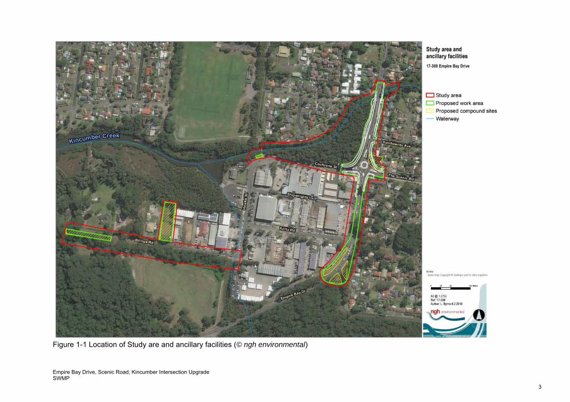
1.2 Background The implementation of the mitigation measures in this SWMP will assist to substantially reduce the potential impacts on surface and groundwater quality in the Study Area. The location of the proposal is shown in Figure 1-2.
Empire Bay Drive, Scenic Road, Kincumber Intersection Upgrade SWMP
3
Figure 1-1 Location of Study are and ancillary facilities (© ngh environmental)
Empire Bay Drive, Scenic Road, Kincumber Intersection Upgrade SWMP
4
2 Legal and Other Requirements
2.1 Legislation Legislation relevant to soil and water management includes: Environmental Planning and Assessment Act 1979 (EP&A Act) Environmental Planning and Assessment Regulation 2000 Protection of the Environment Operations Act 1997 (POEO Act) Water Management Act 2000 (WM Act) Fisheries Management Act 1994 (FM Act) Commonwealth Environment Protection and Biodiversity Conservation Act 1999 (EPBC Act) Water Act 1912 (Water Act).
2.2 Guidelines and Standards The main guidelines, specifications and policy documents relevant to this WMP include: Acid Sulfate Soil Manual (ASSMAC 1998) Acid Sulfate Soil and Rock – Victorian EPA Publication 655.1 – July 2009 Australian and New Zealand Guidelines for Fresh and Marine Water Quality (ANZECC and
ARMCANZ 2000) National Water Quality Management Strategy (NWQMS) (Department of Sustainability,
Environment, Water, Population and Communities (DSEWPC), 1994) NSW Water Quality and River Flow Objectives (DECCW, 2006) Department of Environment and Conservation (DEC): Bunding & Spill Management. Insert to the Environment Protection Manual for Authorised Officers - Technical section
"Bu" November 1997 Managing Urban Stormwater: Soils and Construction. Landcom, (4th Edition) March 2004
(reprinted 2006) (the “Blue Book”). Volume 1 and Volume 2 Volume 2A Installation of Services (DECCW 2008) Volume 2C Unsealed Roads (DECCW 2008) Volume 2D Main Roads Construction (DECCW 2008) DIPNR Roads and Salinity Guideline, 2003 DLWC, 1998. Constructed Wetlands Manual Fairfull, S. and Witheridge, G. (2003) Why do Fish Need to Cross the Road? Fish Passage
Requirements for Waterway Crossings. NSW Fisheries, Cronulla, 16 pp NSW Fisheries, November 2003. Fishnote – Policy and Guidelines for Fish Friendly Waterway Crossings (Ref: NSWF – 1181) RMS Pacific Highway Practice Note for Dewatering RTA’s Code of Practice for Water Management – Road Development and Management (1999) Approved Methods for the Sampling and Analysis of Water Pollutants in NSW (EPA, March
2004) Guidelines for the Management of Acid Sulphate materials: Acid Sulphate Soils, Acid Sulphate
Rock and Monosulphidic Black Ooze (RTA 2005) RMS Environment Direction Management of Tannins from Vegetation Mulch RMS Technical Guideline: Temporary stormwater drainage for road construction Stockpile Site
Management Guideline, RMS 2011 Environmental Best Management Practice Guideline for Concreting Contractors (DEC, 2004 RMS Road Design Guideline: Section 8 Erosion and Sedimentation (RTA, 2003) RMS Guideline for Construction Phase Water Quality Monitoring (RTA, n.d.) RMS Erosion and Sedimentation Management Procedure (RTA, 2009) Procedures for Selecting Treatment Strategies to Control Road Runoff (RTA, 2003a) RMS Water Policy (RTA, 1997) Road Runoff and Drainage: Environmental Impacts and Management Options, AP-R180
(Austroads, 2001)
Empire Bay Drive, Scenic Road, Kincumber Intersection Upgrade SWMP
5
Floodplain Development Manual (NSW Government, 2005) RMS Technical Guideline: Environmental Management of Construction Site Dewatering (RTA,
2011) Coastal Lakes: Independent Inquiry into Coastal Lakes and Statement of Joint Intent (Healthy
Rivers Commission of NSW, 2002) The relevant targets within the State Water Management Outcomes Plan (NOW, 2003) State Groundwater Policy Framework Document (Department of Land and Water Conservation
(DLWC), 1997) he NSW State Groundwater Quality Protection Policy (DLWC, 1998) (Draft) NSW State Groundwater Quantity Management Policy (DLWC, n.d.) NSW State Groundwater Dependent Ecosystems Policy (DLWC, 2002) National Water Quality Management Strategy Guidelines for Groundwater Protection in
Australia (Agriculture and Resource Management Council of Australia and New Zealand (ARMCANZ) and ANZECC, 1995)
Guidelines for Treatment of Stormwater Runoff from Road Infrastructure, AP-R232 (Austroads, 2003)
Guidelines for the Assessment and Management of Groundwater Contamination (NSW DEC, 2007).
Empire Bay Drive, Scenic Road, Kincumber Intersection Upgrade SWMP
6
3 Existing Environment
The following sections summarise the factors influencing soil and water within and adjacent to the Proposal.
3.1 Geology and Soils
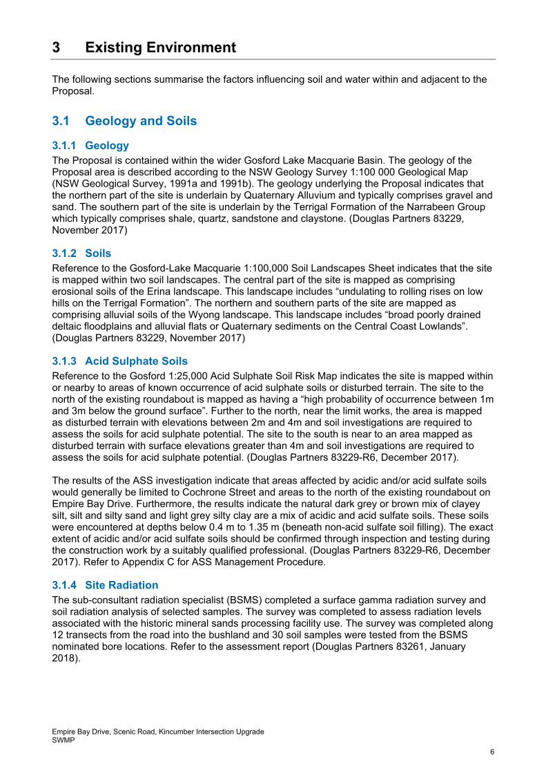
3.1.1 Geology The Proposal is contained within the wider Gosford Lake Macquarie Basin. The geology of the Proposal area is described according to the NSW Geology Survey 1:100 000 Geological Map (NSW Geological Survey, 1991a and 1991b). The geology underlying the Proposal indicates that the northern part of the site is underlain by Quaternary Alluvium and typically comprises gravel and sand. The southern part of the site is underlain by the Terrigal Formation of the Narrabeen Group which typically comprises shale, quartz, sandstone and claystone. (Douglas Partners 83229, November 2017)
3.1.2 Soils Reference to the Gosford-Lake Macquarie 1:100,000 Soil Landscapes Sheet indicates that the site is mapped within two soil landscapes. The central part of the site is mapped as comprising erosional soils of the Erina landscape. This landscape includes “undulating to rolling rises on low hills on the Terrigal Formation”. The northern and southern parts of the site are mapped as comprising alluvial soils of the Wyong landscape. This landscape includes “broad poorly drained deltaic floodplains and alluvial flats or Quaternary sediments on the Central Coast Lowlands”. (Douglas Partners 83229, November 2017)
3.1.3 Acid Sulphate Soils Reference to the Gosford 1:25,000 Acid Sulphate Soil Risk Map indicates the site is mapped within or nearby to areas of known occurrence of acid sulphate soils or disturbed terrain. The site to the north of the existing roundabout is mapped as having a “high probability of occurrence between 1m and 3m below the ground surface”. Further to the north, near the limit works, the area is mapped as disturbed terrain with elevations between 2m and 4m and soil investigations are required to assess the soils for acid sulphate potential. The site to the south is near to an area mapped as disturbed terrain with surface elevations greater than 4m and soil investigations are required to assess the soils for acid sulphate potential. (Douglas Partners 83229-R6, December 2017). The results of the ASS investigation indicate that areas affected by acidic and/or acid sulfate soils would generally be limited to Cochrone Street and areas to the north of the existing roundabout on Empire Bay Drive. Furthermore, the results indicate the natural dark grey or brown mix of clayey silt, silt and silty sand and light grey silty clay are a mix of acidic and acid sulfate soils. These soils were encountered at depths below 0.4 m to 1.35 m (beneath non-acid sulfate soil filling). The exact extent of acidic and/or acid sulfate soils should be confirmed through inspection and testing during the construction work by a suitably qualified professional. (Douglas Partners 83229-R6, December 2017). Refer to Appendix C for ASS Management Procedure.
3.1.4 Site Radiation The sub-consultant radiation specialist (BSMS) completed a surface gamma radiation survey and soil radiation analysis of selected samples. The survey was completed to assess radiation levels associated with the historic mineral sands processing facility use. The survey was completed along 12 transects from the road into the bushland and 30 soil samples were tested from the BSMS nominated bore locations. Refer to the assessment report (Douglas Partners 83261, January 2018).
Empire Bay Drive, Scenic Road, Kincumber Intersection Upgrade SWMP
7
The surface gamma radiation survey reported radiation levels below the assessment limit for roads and footpaths (i.e. 2.5 μSv/hr). Furthermore, BSMS concluded that there were no soil concentration results that would impact humans during the proposed construction activities. However, a small area identified as KCR-T2 reported results (i.e. maximum of 0.82 μSv/hr) above the NSW Guideline for residential use (0.7 μSv/hr). This radiation level would prevent the beneficial use of this soil at an offsite location, but it would not prevent disposal to an appropriately licensed landfill. Radiation levels in soil are not sufficiently high for the material to be classified as radioactive. (Douglas Partners 83261, January 2018).
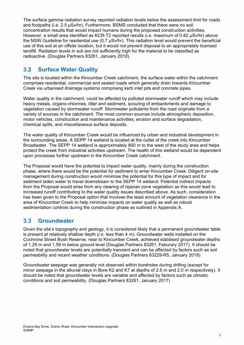
3.2 Surface Water Quality The site is located within the Kincumber Creek catchment, the surface water within the catchment comprises residential, commercial and sealed roads which generally drain towards Kincumber Creek via urbanised drainage systems comprising kerb inlet pits and concrete pipes. Water quality in the catchment, could be affected by polluted stormwater runoff which may include heavy metals, organo-chlorines, litter and sediment, scouring of embankments and damage to vegetation caused by stormwater runoff. Stormwater pollutants from the road originate from a variety of sources in the catchment. The most common sources include atmospheric deposition, motor vehicles, construction and maintenance activities, erosion and surface degradation, chemical spills, and miscellaneous surface deposits. The water quality of Kincumber Creek would be influenced by urban and industrial development in the surrounding areas. A SEPP 14 wetland is located at the outlet of the creek into Kincumber Broadwater. The SEPP 14 wetland is approximately 800 m to the west of the study area and helps protect the creek from industrial activities upstream. The health of this wetland would be dependent upon processes further upstream in the Kincumber Creek catchment. The Proposal would have the potential to impact water quality, mainly during the construction phase, where there would be the potential for sediment to enter Kincumber Creek. Diligent on-site management during construction would minimise the potential for this type of impact and for sediment laden water to travel downstream to the SEPP 14 wetland. Potential indirect impacts from the Proposal would arise from any clearing of riparian zone vegetation as this would lead to increased runoff contributing to the water quality issues described above. As such, consideration has been given to the Proposal option that involves the least amount of vegetation clearance in the area of Kincumber Creek to help minimise impacts on water quality as well as robust sedimentation controls during the construction phase as outlined in Appendix A.
3.3 Groundwater Given the site’s topography and geology, it is considered likely that a permanent groundwater table is present at relatively shallow depth (i.e. less than 4 m). Groundwater wells installed on the Cochrone Street Bush Reserve, near to Kincumber Creek, achieved stabilised groundwater depths of 1.29 m and 1.59 m below ground level (Douglas Partners 83261, Feburary 2017). It should be noted that groundwater levels are potentially transient and can be affected by factors such as soil permeability and recent weather conditions. (Douglas Partners 83229-R5, January 2018) Groundwater seepage was generally not observed within boreholes during drilling (except for minor seepage in the alluvial clays in Bore K2 and K7 at depths of 2.6 m and 2.0 m respectively). It should be noted that groundwater levels are variable and affected by factors such as climatic conditions and soil permeability. (Douglas Partners 83261, January 2017)
Empire Bay Drive, Scenic Road, Kincumber Intersection Upgrade SWMP
8
3.4 Climate The Central Coast region is characterised by mild-to-warm summers and cold winters. Meteorological data are collected by the Bureau of Meteorology (BoM), and the closest BoM weather station is located at Gosford AWS, about 5 km to the west of the Proposal. January is the hottest month, with a mean maximum temperature of 27.8ºC, and July is the coldest month with a mean minimum temperature of 6.5ºC. February is the wettest month with a mean rainfall of 158.4mm and July is the driest month with a mean rainfall of 68.3mm.
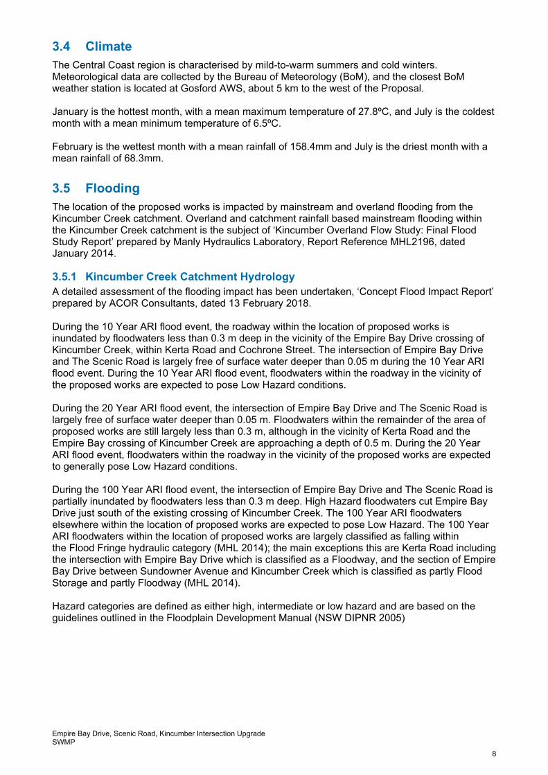
3.5 Flooding The location of the proposed works is impacted by mainstream and overland flooding from the Kincumber Creek catchment. Overland and catchment rainfall based mainstream flooding within the Kincumber Creek catchment is the subject of ‘Kincumber Overland Flow Study: Final Flood Study Report’ prepared by Manly Hydraulics Laboratory, Report Reference MHL2196, dated January 2014.
3.5.1 Kincumber Creek Catchment Hydrology A detailed assessment of the flooding impact has been undertaken, ‘Concept Flood Impact Report’ prepared by ACOR Consultants, dated 13 February 2018. During the 10 Year ARI flood event, the roadway within the location of proposed works is inundated by floodwaters less than 0.3 m deep in the vicinity of the Empire Bay Drive crossing of Kincumber Creek, within Kerta Road and Cochrone Street. The intersection of Empire Bay Drive and The Scenic Road is largely free of surface water deeper than 0.05 m during the 10 Year ARI flood event. During the 10 Year ARI flood event, floodwaters within the roadway in the vicinity of the proposed works are expected to pose Low Hazard conditions. During the 20 Year ARI flood event, the intersection of Empire Bay Drive and The Scenic Road is largely free of surface water deeper than 0.05 m. Floodwaters within the remainder of the area of proposed works are still largely less than 0.3 m, although in the vicinity of Kerta Road and the Empire Bay crossing of Kincumber Creek are approaching a depth of 0.5 m. During the 20 Year ARI flood event, floodwaters within the roadway in the vicinity of the proposed works are expected to generally pose Low Hazard conditions. During the 100 Year ARI flood event, the intersection of Empire Bay Drive and The Scenic Road is partially inundated by floodwaters less than 0.3 m deep. High Hazard floodwaters cut Empire Bay Drive just south of the existing crossing of Kincumber Creek. The 100 Year ARI floodwaters elsewhere within the location of proposed works are expected to pose Low Hazard. The 100 Year ARI floodwaters within the location of proposed works are largely classified as falling within the Flood Fringe hydraulic category (MHL 2014); the main exceptions this are Kerta Road including the intersection with Empire Bay Drive which is classified as a Floodway, and the section of Empire Bay Drive between Sundowner Avenue and Kincumber Creek which is classified as partly Flood Storage and partly Floodway (MHL 2014). Hazard categories are defined as either high, intermediate or low hazard and are based on the guidelines outlined in the Floodplain Development Manual (NSW DIPNR 2005)
Empire Bay Drive, Scenic Road, Kincumber Intersection Upgrade SWMP
9
4 Environmental Aspects and Impacts
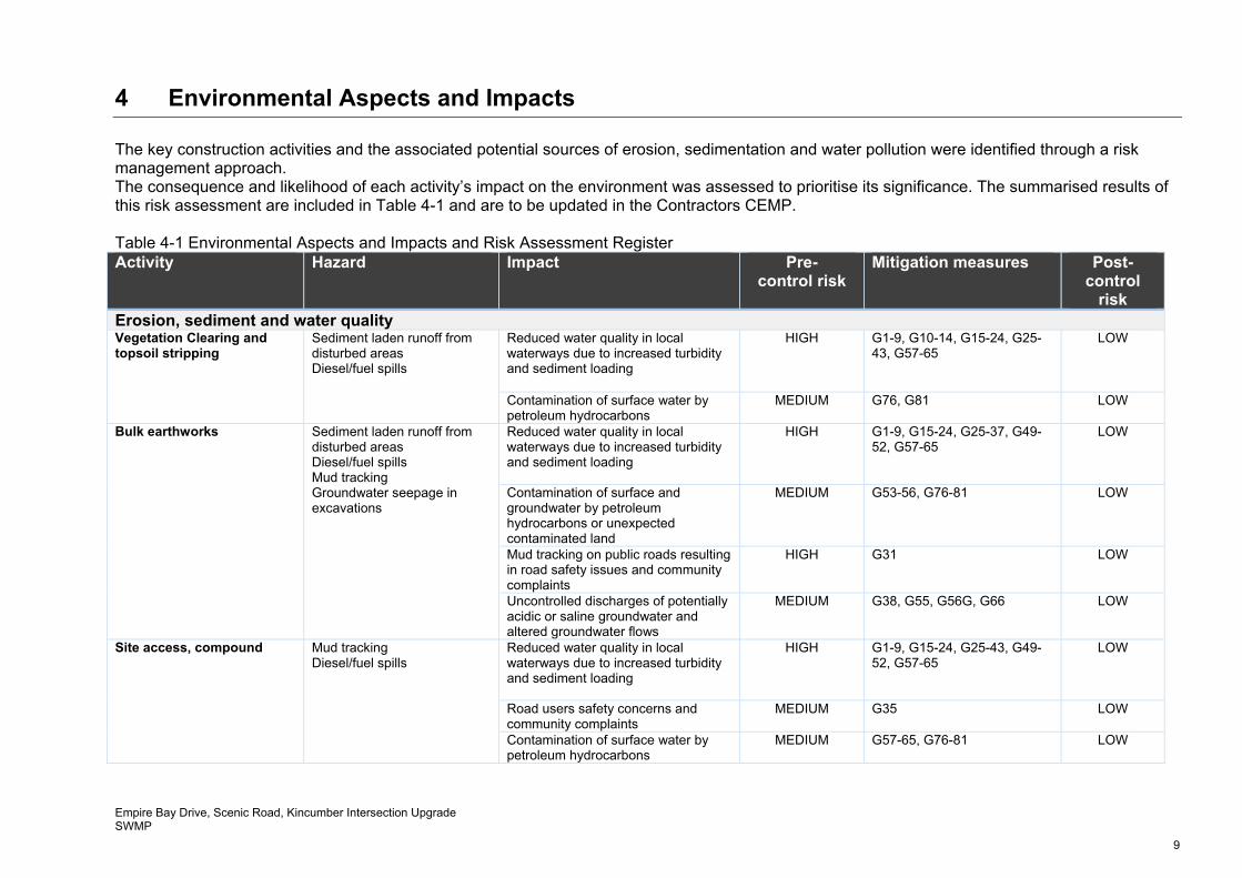
The key construction activities and the associated potential sources of erosion, sedimentation and water pollution were identified through a risk management approach. The consequence and likelihood of each activity’s impact on the environment was assessed to prioritise its significance. The summarised results of this risk assessment are included in Table 4-1 and are to be updated in the Contractors CEMP. Table 4-1 Environmental Aspects and Impacts and Risk Assessment Register Activity Hazard Impact Pre-
control risk Mitigation measures Post-
control risk
Erosion, sediment and water quality Vegetation Clearing and topsoil stripping
Sediment laden runoff from disturbed areas Diesel/fuel spills
Reduced water quality in local waterways due to increased turbidity and sediment loading
HIGH G1-9, G10-14, G15-24, G25-43, G57-65
LOW
Contamination of surface water by petroleum hydrocarbons
MEDIUM G76, G81 LOW
Bulk earthworks Sediment laden runoff from disturbed areas Diesel/fuel spills Mud tracking Groundwater seepage in excavations
Reduced water quality in local waterways due to increased turbidity and sediment loading
HIGH G1-9, G15-24, G25-37, G49-52, G57-65
LOW
Contamination of surface and groundwater by petroleum hydrocarbons or unexpected contaminated land
MEDIUM G53-56, G76-81 LOW
Mud tracking on public roads resulting in road safety issues and community complaints
HIGH G31 LOW
Uncontrolled discharges of potentially acidic or saline groundwater and altered groundwater flows
MEDIUM G38, G55, G56G, G66 LOW
Site access, compound Mud tracking Diesel/fuel spills
Reduced water quality in local waterways due to increased turbidity and sediment loading
HIGH G1-9, G15-24, G25-43, G49-52, G57-65
LOW
Road users safety concerns and community complaints
MEDIUM G35 LOW
Contamination of surface water by petroleum hydrocarbons
MEDIUM G57-65, G76-81 LOW
Empire Bay Drive, Scenic Road, Kincumber Intersection Upgrade SWMP
10
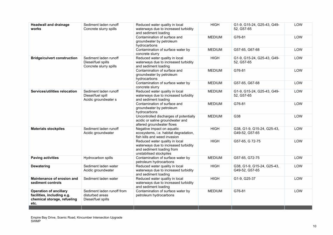
Headwall and drainage works
Sediment laden runoff Concrete slurry spills
Reduced water quality in local waterways due to increased turbidity and sediment loading
HIGH G1-9, G15-24, G25-43, G49-52, G57-65
LOW
Contamination of surface and groundwater by petroleum hydrocarbons
MEDIUM G76-81 LOW
Contamination of surface water by concrete slurry
MEDIUM G57-65, G67-68 LOW
Bridge/culvert construction Sediment laden runoff Diesel/fuel spills Concrete slurry spills
Reduced water quality in local waterways due to increased turbidity and sediment loading
HIGH G1-9, G15-24, G25-43, G49-52, G57-65
LOW
Contamination of surface and groundwater by petroleum hydrocarbons
MEDIUM G76-81 LOW
Contamination of surface water by concrete slurry
MEDIUM G57-65, G67-68 LOW
Services/utilities relocation Sediment laden runoff Diesel/fuel spill Acidic groundwater s
Reduced water quality in local waterways due to increased turbidity and sediment loading
MEDIUM G1-9, G15-24, G25-43, G49-52, G57-65
LOW
Contamination of surface and groundwater by petroleum hydrocarbons
MEDIUM G76-81 LOW
Uncontrolled discharges of potentially acidic or saline groundwater and altered groundwater flows
MEDIUM G38 LOW
Materials stockpiles Sediment laden runoff Acidic groundwater
Negative impact on aquatic ecosystems, i.e. habitat degradation, fish kills and weed invasion
HIGH G38, G1-9, G15-24, G25-43, G49-52, G57-65
LOW
Reduced water quality in local waterways due to increased turbidity and sediment loading from unstabilised stockpiles
HIGH G57-65, G 72-75 LOW
Paving activities Hydrocarbon spills Contamination of surface water by petroleum hydrocarbons
MEDIUM G57-65, G72-75 LOW
Dewatering Sediment laden water Acidic groundwater
Reduced water quality in local waterways due to increased turbidity and sediment loading
HIGH G38, G1-9, G15-24, G25-43, G49-52, G57-65
LOW
Maintenance of erosion and sediment controls
Sediment laden water Reduced water quality in local waterways due to increased turbidity and sediment loading
HIGH G1-9, G25-37 LOW
Operation of ancillary facilities, including e.g. chemical storage, refueling etc.
Sediment laden runoff from disturbed areas Diesel/fuel spills
Contamination of surface water by petroleum hydrocarbons
MEDIUM G76-81 LOW
Empire Bay Drive, Scenic Road, Kincumber Intersection Upgrade SWMP
11
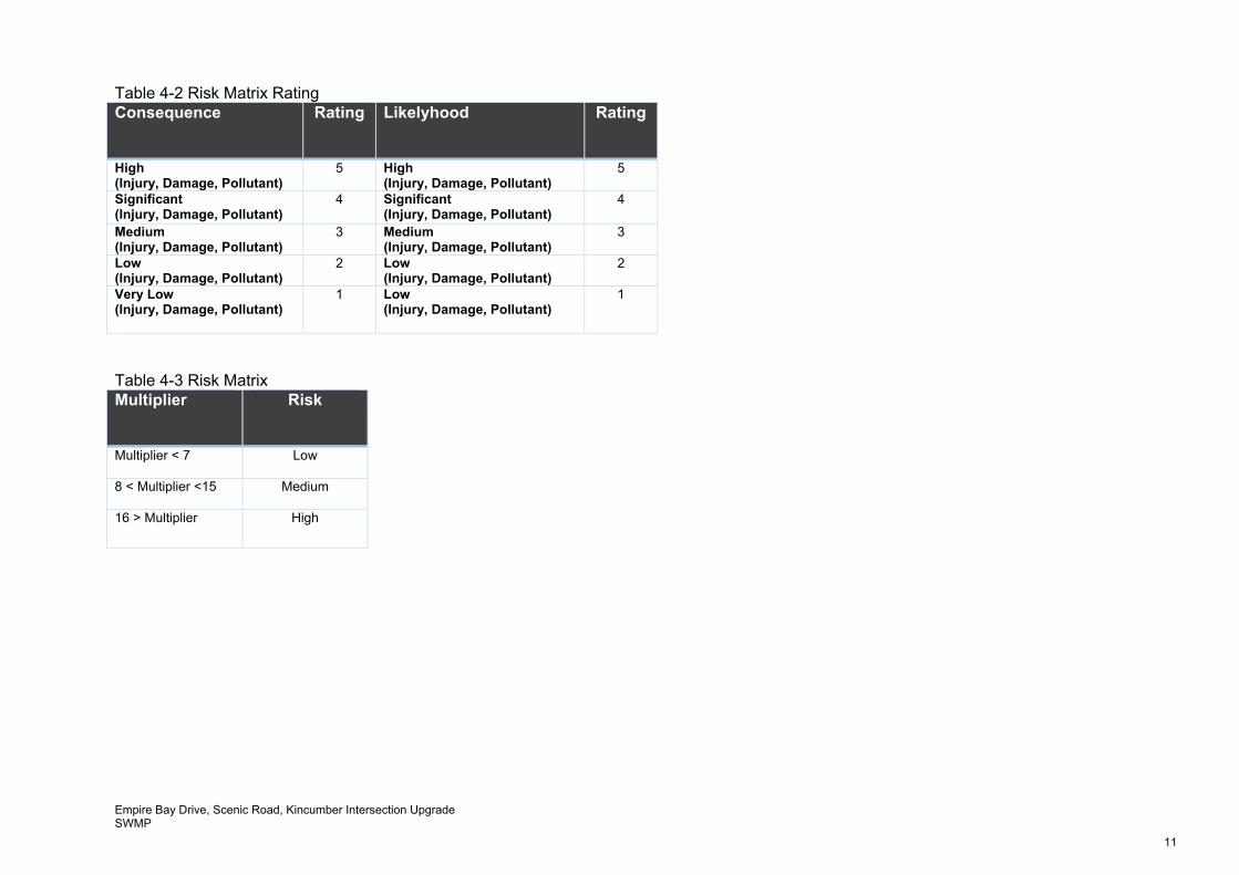
Table 4-2 Risk Matrix Rating Consequence Rating Likelyhood Rating
High (Injury, Damage, Pollutant)
5
High (Injury, Damage, Pollutant)
5
Significant (Injury, Damage, Pollutant)
4
Significant (Injury, Damage, Pollutant)
4
Medium (Injury, Damage, Pollutant)
3
Medium (Injury, Damage, Pollutant)
3
Low (Injury, Damage, Pollutant)
2
Low (Injury, Damage, Pollutant)
2
Very Low (Injury, Damage, Pollutant)
1 Low (Injury, Damage, Pollutant)
1
Table 4-3 Risk Matrix Multiplier Risk
Multiplier < 7
Low
8 < Multiplier <15
Medium
16 > Multiplier High
Empire Bay Drive, Scenic Road, Kincumber Intersection Upgrade SWMP
12
5 Environmental Mitigation Measures
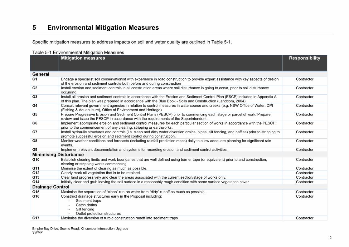
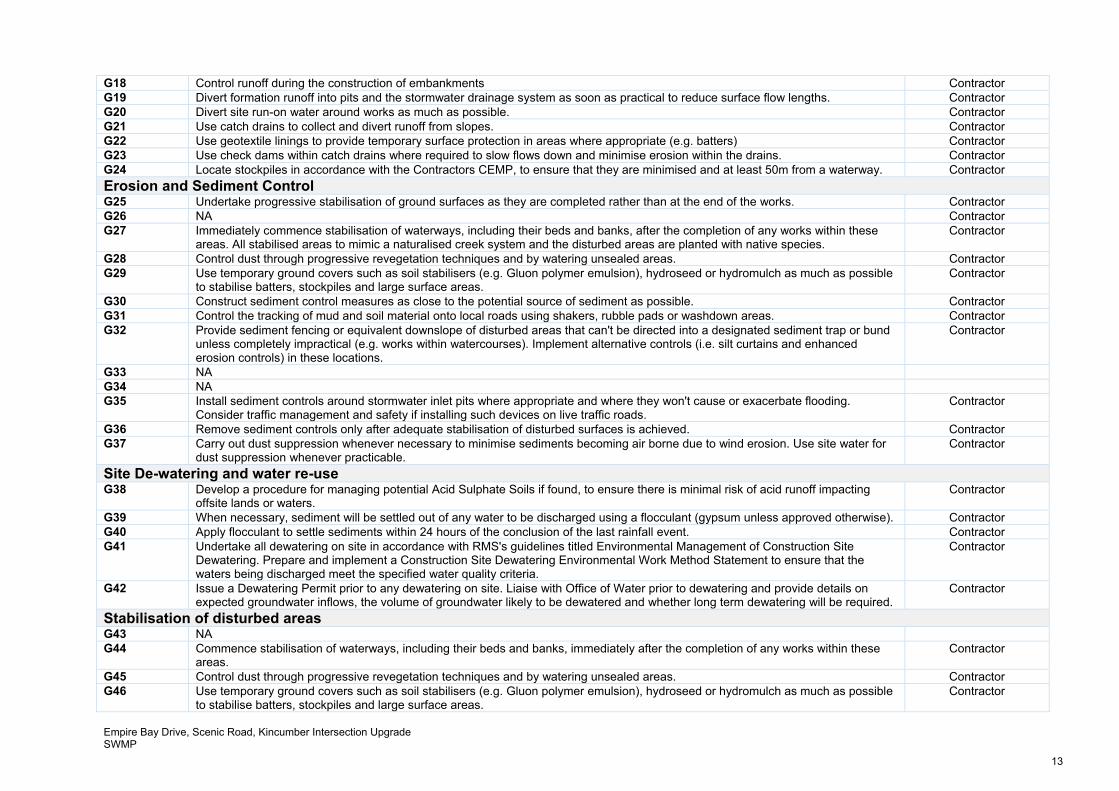
Specific mitigation measures to address impacts on soil and water quality are outlined in Table 5-1. Table 5-1 Environmental Mitigation Measures Mitigation measures Responsibility
General G1 Engage a specialist soil conservationist with experience in road construction to provide expert assistance with key aspects of design
of the erosion and sediment controls both before and during construction Contractor
G2 Install erosion and sediment controls in all construction areas where soil disturbance is going to occur, prior to soil disturbance occurring.
Contractor
G3 Install all erosion and sediment controls in accordance with the Erosion and Sediment Control Plan (ESCP) included in Appendix A of this plan. The plan was prepared in accordance with the Blue Book - Soils and Construction (Landcom, 2004).
Contractor
G4 Consult relevant government agencies in relation to control measures in watercourse and creeks (e.g. NSW Office of Water, DPI (Fishing & Aquaculture), Office of Environment and Heritage)
Contractor
G5 Prepare Progressive Erosion and Sediment Control Plans (PESCP) prior to commencing each stage or parcel of work. Prepare, review and issue the PESCP in accordance with the requirements of the Superintendent.
Contractor
G6 Implement appropriate erosion and sediment control measures for each particular section of works in accordance with the PESCP, prior to the commencement of any clearing, stripping or earthworks.
Contractor
G7 Install hydraulic structures and controls (i.e. clean and dirty water diversion drains, pipes, silt fencing, and baffles) prior to stripping to promote successful erosion and sediment control during construction.
Contractor
G8 Monitor weather conditions and forecasts (including rainfall prediction maps) daily to allow adequate planning for significant rain events.
Contractor
G9 Implement relevant documentation and systems for recording erosion and sediment control activities. Contractor
Minimising Disturbance G10 Establish clearing limits and work boundaries that are well defined using barrier tape (or equivalent) prior to and construction,
clearing or stripping works commencing. Contractor
G11 Minimise the extent of clearing as much as possible. Contractor G12 Clearly mark all vegetation that is to be retained. Contractor G13 Clear land progressively and clear the areas associated with the current section/stage of works only. Contractor G14 Initially clear and grub leaving the soil surface in a reasonably rough condition with some surface vegetation cover. Contractor
Drainage Control G15 Maximise the separation of “clean” run-on water from “dirty” runoff as much as possible. Contractor G16 Construct drainage structures early in the Proposal including:
- Sediment traps - Catch drains - Silt fencing - Outlet protection structures
Contractor
G17 Maximise the diversion of turbid construction runoff into sediment traps Contractor
Empire Bay Drive, Scenic Road, Kincumber Intersection Upgrade SWMP
13
G18 Control runoff during the construction of embankments Contractor G19 Divert formation runoff into pits and the stormwater drainage system as soon as practical to reduce surface flow lengths. Contractor G20 Divert site run-on water around works as much as possible. Contractor G21 Use catch drains to collect and divert runoff from slopes. Contractor G22 Use geotextile linings to provide temporary surface protection in areas where appropriate (e.g. batters) Contractor G23 Use check dams within catch drains where required to slow flows down and minimise erosion within the drains. Contractor G24 Locate stockpiles in accordance with the Contractors CEMP, to ensure that they are minimised and at least 50m from a waterway. Contractor
Erosion and Sediment Control G25 Undertake progressive stabilisation of ground surfaces as they are completed rather than at the end of the works. Contractor G26 NA Contractor G27 Immediately commence stabilisation of waterways, including their beds and banks, after the completion of any works within these
areas. All stabilised areas to mimic a naturalised creek system and the disturbed areas are planted with native species. Contractor
G28 Control dust through progressive revegetation techniques and by watering unsealed areas. Contractor G29 Use temporary ground covers such as soil stabilisers (e.g. Gluon polymer emulsion), hydroseed or hydromulch as much as possible
to stabilise batters, stockpiles and large surface areas. Contractor
G30 Construct sediment control measures as close to the potential source of sediment as possible. Contractor G31 Control the tracking of mud and soil material onto local roads using shakers, rubble pads or washdown areas. Contractor G32 Provide sediment fencing or equivalent downslope of disturbed areas that can't be directed into a designated sediment trap or bund
unless completely impractical (e.g. works within watercourses). Implement alternative controls (i.e. silt curtains and enhanced erosion controls) in these locations.
Contractor
G33 NA G34 NA G35 Install sediment controls around stormwater inlet pits where appropriate and where they won't cause or exacerbate flooding.
Consider traffic management and safety if installing such devices on live traffic roads. Contractor
G36 Remove sediment controls only after adequate stabilisation of disturbed surfaces is achieved. Contractor G37 Carry out dust suppression whenever necessary to minimise sediments becoming air borne due to wind erosion. Use site water for
dust suppression whenever practicable. Contractor
Site De-watering and water re-use G38 Develop a procedure for managing potential Acid Sulphate Soils if found, to ensure there is minimal risk of acid runoff impacting
offsite lands or waters. Contractor
G39 When necessary, sediment will be settled out of any water to be discharged using a flocculant (gypsum unless approved otherwise). Contractor G40 Apply flocculant to settle sediments within 24 hours of the conclusion of the last rainfall event. Contractor G41 Undertake all dewatering on site in accordance with RMS's guidelines titled Environmental Management of Construction Site
Dewatering. Prepare and implement a Construction Site Dewatering Environmental Work Method Statement to ensure that the waters being discharged meet the specified water quality criteria.
Contractor
G42 Issue a Dewatering Permit prior to any dewatering on site. Liaise with Office of Water prior to dewatering and provide details on expected groundwater inflows, the volume of groundwater likely to be dewatered and whether long term dewatering will be required.
Contractor
Stabilisation of disturbed areas G43 NA G44 Commence stabilisation of waterways, including their beds and banks, immediately after the completion of any works within these
areas. Contractor
G45 Control dust through progressive revegetation techniques and by watering unsealed areas. Contractor G46 Use temporary ground covers such as soil stabilisers (e.g. Gluon polymer emulsion), hydroseed or hydromulch as much as possible
to stabilise batters, stockpiles and large surface areas. Contractor
Empire Bay Drive, Scenic Road, Kincumber Intersection Upgrade SWMP
14
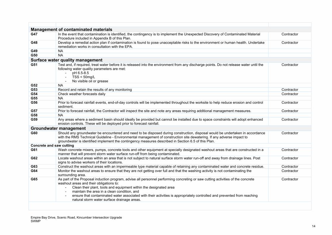
Management of contaminated materials G47 In the event that contamination is identified, the contingency is to implement the Unexpected Discovery of Contaminated Material
Procedure included in Appendix B of this Plan. Contractor
G48 Develop a remedial action plan if contamination is found to pose unacceptable risks to the environment or human health. Undertake remediation works in consultation with the EPA.
Contractor
G49 NA G50 NA
Surface water quality management G51 Test and, if required, treat water before it is released into the environment from any discharge points. Do not release water until the
following water quality parameters are met: - pH 6.5-8.5 - TSS < 50mg/L - No visible oil or grease
Contractor
G52 NA G53 Record and retain the results of any monitoring Contractor G54 Check weather forecasts daily Contractor G55 NA G56 Prior to forecast rainfall events, end-of-day controls will be implemented throughout the worksite to help reduce erosion and control
sediment. Contractor
G57 Prior to forecast rainfall, the Contractor will inspect the site and note any areas requiring additional management measures. Contractor G58 NA G59 Any areas where a sediment basin should ideally be provided but cannot be installed due to space constraints will adopt enhanced
erosion controls. These will be deployed prior to forecast rainfall. Contractor
Groundwater management G60 Should any groundwater be encountered and need to be disposed during construction, disposal would be undertaken in accordance
with the RMS Technical Guideline - Environmental management of construction site dewatering. If any adverse impact to groundwater is identified implement the contingency measures described in Section 6.5 of this Plan.
Contractor
Concrete and saw cutting G61 Wash concrete mixers, pumps, concrete tools and other equipment at specially designated washout areas that are constructed in a
manner that will prevent storm water surface run-off from being contaminated. Contractor
G62 Locate washout areas within an area that is not subject to natural surface storm water run-off and away from drainage lines. Post signs to advise workers of their locations.
Contractor
G63 Construct the washout areas with an impermeable type material capable of retaining any contaminated water and concrete residue. Contractor G64 Monitor the washout areas to ensure that they are not getting over full and that the washing activity is not contaminating the
surrounding area. Contractor
G65 As part of the Proposal induction program, advise all personnel performing concreting or saw cutting activities of the concrete washout areas and their obligations to:
- Clean their plant, tools and equipment within the designated area - maintain the area in a clean condition, and - ensure that contaminated water associated with their activities is appropriately controlled and prevented from reaching
natural storm water surface drainage areas.
Contractor
Empire Bay Drive, Scenic Road, Kincumber Intersection Upgrade SWMP
15
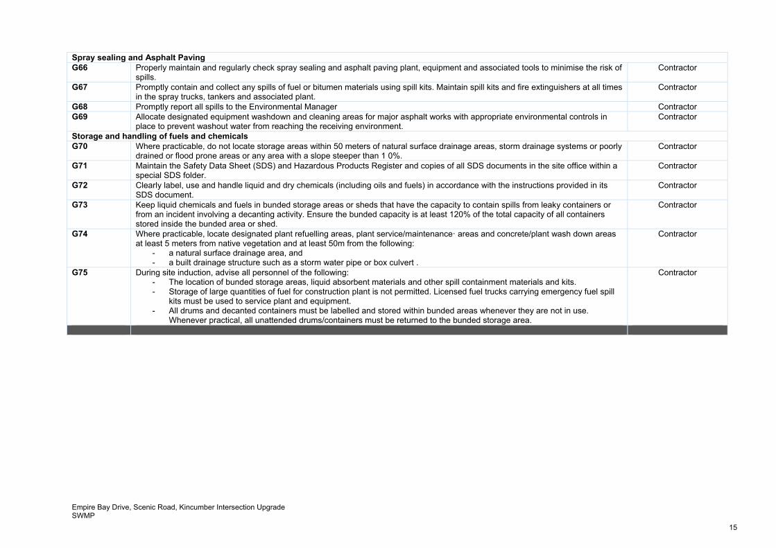
Spray sealing and Asphalt Paving G66 Properly maintain and regularly check spray sealing and asphalt paving plant, equipment and associated tools to minimise the risk of
spills. Contractor
G67 Promptly contain and collect any spills of fuel or bitumen materials using spill kits. Maintain spill kits and fire extinguishers at all times in the spray trucks, tankers and associated plant.
Contractor
G68 Promptly report all spills to the Environmental Manager Contractor G69 Allocate designated equipment washdown and cleaning areas for major asphalt works with appropriate environmental controls in
place to prevent washout water from reaching the receiving environment. Contractor
Storage and handling of fuels and chemicals G70 Where practicable, do not locate storage areas within 50 meters of natural surface drainage areas, storm drainage systems or poorly
drained or flood prone areas or any area with a slope steeper than 1 0%. Contractor
G71 Maintain the Safety Data Sheet (SDS) and Hazardous Products Register and copies of all SDS documents in the site office within a special SDS folder.
Contractor
G72 Clearly label, use and handle liquid and dry chemicals (including oils and fuels) in accordance with the instructions provided in its SDS document.
Contractor
G73 Keep liquid chemicals and fuels in bunded storage areas or sheds that have the capacity to contain spills from leaky containers or from an incident involving a decanting activity. Ensure the bunded capacity is at least 120% of the total capacity of all containers stored inside the bunded area or shed.
Contractor
G74 Where practicable, locate designated plant refuelling areas, plant service/maintenanceꞏ areas and concrete/plant wash down areas at least 5 meters from native vegetation and at least 50m from the following:
- a natural surface drainage area, and - a built drainage structure such as a storm water pipe or box culvert .
Contractor
G75 During site induction, advise all personnel of the following: - The location of bunded storage areas, liquid absorbent materials and other spill containment materials and kits. - Storage of large quantities of fuel for construction plant is not permitted. Licensed fuel trucks carrying emergency fuel spill
kits must be used to service plant and equipment. - All drums and decanted containers must be labelled and stored within bunded areas whenever they are not in use.
Whenever practical, all unattended drums/containers must be returned to the bunded storage area.
Contractor
Empire Bay Drive, Scenic Road, Kincumber Intersection Upgrade SWMP
16
6 Compliance Management
6.1 Roles and Responsibilities The Contractors organisational structure and overall roles and responsibilities are to be outlined in the CEMP. Specific responsibilities for the implementation of environmental controls are to be detailed in the CEMP.
6.2 Training All employees, contractors and utility staff working on site will undergo site induction training relating to soil and water management issues, including: Existence and requirements of this SWMP Relevant legislation Roles and responsibilities for soil and water management Water quality management and protection measures Groundwater issues Procedure to be implemented in the event of an unexpected discovery of contaminated
land. Targeted training in the form of toolbox talks or specific training will also be provided to personnel with a key role in soil and water management. Examples of training topics include: Erosion and Sediment control installation methodology Working near or in drainage lines and creeks Emergency response measures in high rainfall events Preparedness for high rainfall events Lessons learnt from incidents and other event e.g. high rainfall or flooding Mulch and tannin management Spill response Stockpile location criteria Identification of potentially contaminated spoil and fill material.
Further details regarding staff induction and training are to be outlined in the Contractors CEMP.
6.3 Environmental Work Method Statements Environmental Work Method Statements (EWMS) are to be prepared progressively by the Contractor to manage and control high-risk construction activities that have potential to adversely impact the environment. EWMS will be prepared prior to the commencement of particular construction activities (i.e. works near Kincumber Creek) and will incorporate area-specific mitigation measures and controls. EWMS for activities which may be considered high risk as identified in Table 4-1 will likely include the following: Working in or adjacent environmentally sensitive areas (Adjacent Kincumber Creek: e.g.
Culvert Construction, Headwall Construction) Site compound establishment Clearing and grubbing Bulk Earthworks Dewatering Works near acid sulphate soils
6.4 Progressive Erosion and Sediment Control Plans Progressive Erosion and Sediment Control Plans (PESCPs) are used to identify the approximate location of erosion and sediment control structures within the Proposal site. They are produced for construction stages from initial vegetation clearing to rehabilitation, when erosion and sediment controls are no longer required and are removed. PESCPs will be developed
Empire Bay Drive, Scenic Road, Kincumber Intersection Upgrade SWMP
17
and implemented prior to commencing activities at all works areas where there is a risk of erosion and sediment loss. PESCPs may be produced in conjunction with EWMS to provide more detailed site-specific environmental mitigation measures. PESCPs will be developed by the Contractors Project Engineers and reviewed and approved by the Contractors Environmental Representative and Site Superintendent. They will be reviewed and revised regularly to reflect the changing site conditions. If necessary, a Soil Conservationist would also be engaged to provide input or to review the PESCPs.
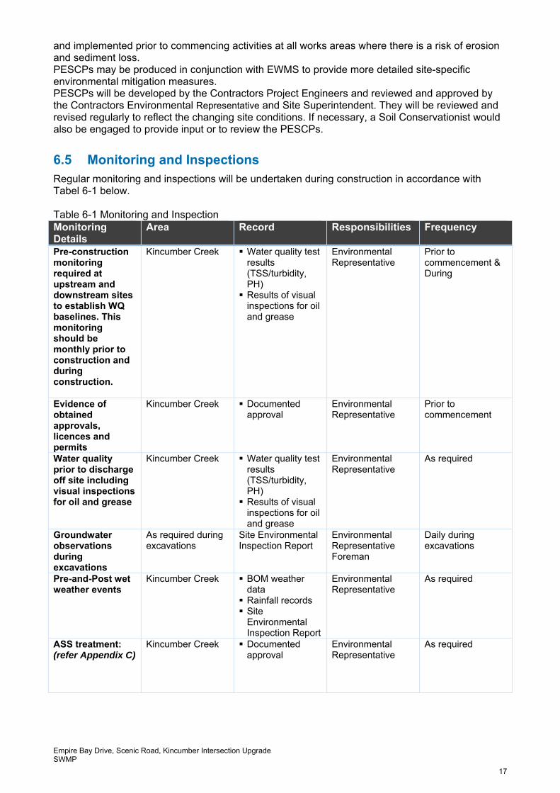
6.5 Monitoring and Inspections Regular monitoring and inspections will be undertaken during construction in accordance with Tabel 6-1 below. Table 6-1 Monitoring and Inspection Monitoring Details
Area Record Responsibilities Frequency
Pre-construction monitoring required at upstream and downstream sites to establish WQ baselines. This monitoring should be monthly prior to construction and during construction.
Kincumber Creek Water quality test results (TSS/turbidity, PH) Results of visual
inspections for oil and grease
Environmental Representative
Prior to commencement & During
Evidence of obtained approvals, licences and permits
Kincumber Creek Documented approval
Environmental Representative
Prior to commencement
Water quality prior to discharge off site including visual inspections for oil and grease
Kincumber Creek Water quality test results (TSS/turbidity, PH) Results of visual
inspections for oil and grease
Environmental Representative
As required
Groundwater observations during excavations
As required during excavations
Site Environmental Inspection Report
Environmental Representative Foreman
Daily during excavations
Pre-and-Post wet weather events
Kincumber Creek BOM weather data Rainfall records Site
Environmental Inspection Report
Environmental Representative
As required
ASS treatment: (refer Appendix C)
Kincumber Creek Documented approval
Environmental Representative
As required
Empire Bay Drive, Scenic Road, Kincumber Intersection Upgrade SWMP
18
6.6 Environmental non-conformances and contingency planning Any environmental non-conformances will be dealt with and documented in in accordance with the contractors CEMP. In the event that adverse impacts to ground or surface water quality are identified as a result of construction activities, the following remediation strategies will be implemented: Implement stop works process in accordance with the Contractors CEMP Ensure area of impact is contained, pump out and contaminated water and dispose it off
site to an appropriately licenced facility Remediate disturbed/affected areas in consultation with NSW Office of Water and other
relevant agencies Review and amend relevant construction method statements Identify and additional water quality monitoring requirements and increase the frequency of
monitoring and site inspection, if warranted. The works will recommence on site once corrective actions have been implemented and preventative actions determined and agreed.
6.7 Complaints Complaints are to be recorded in accordance with an approved Construction Environmental Management Plan.
6.8 Audits Audits (both internal and external) will be undertaken to assess the effectiveness of environmental controls, compliance with this SWMP and other relevant approvals, licences and guidelines.
Empire Bay Drive, Scenic Road, Kincumber Intersection Upgrade SWMP
19
References
Guidance: Provide a reference list consistent with the Harvard referencing style. Manly Hydraulics. (January 2014). ‘Kincumber Overland Flow Study: Final Flood Study Report’ (MHL2196). Landcom. (March 2004).Soils and Construction Volume 1 – Managing Urban Stormwater, 4th Edition. Douglas Partners. (November 2017). Geotechnical Investigation Factual Report Proposed Intersection Upgrade – Empire Bay Drive and the Scenic Road, (REF: 83229-R4) Douglas Partners. (January 2018). Contamination Investigation – Empire Bay Drive and the Scenic Road, (REF: 83229-R5) Douglas Partners. (December 2017). Acid Sulphate Assessment and Management Plan – Empire Bay Drive and Scenic Road (REF: 83229-R6) Douglas Partners. (January 2018). Waste Classification Report – Proposed Intersection Upgrade Road Reserve and Part 4 of Cochrone Street (REF: 83261) Douglas Partners. (February 2018). Report on Detailed Site Investigation for Contamination – Proposed Intersection Upgrade Road Reserve and Part 4 of Cochrone Street (REF: 83261) BSMS. (October 2017) Surface Gamma Radiation Survey and Soil Radiation Analysis For the Proposed RMS Road Works at Empire Bay Drive and Cochrone Street Intersection. ACOR. (January 2018). Concept Flood Impact Report – Empire Bay Drive and Scenic Road
Empire Bay Drive, Scenic Road, Kincumber Intersection Upgrade SWMP
20
Terms and acronyms used in this REF
Term / Acronym Description
CEMP Construction environmental management plan
SWMP Soil and Water Management Report
EIA Environmental impact assessment
EP&A Act Environmental Planning and Assessment Act 1979 (NSW). Provides the legislative framework for land use planning and development assessment in NSW
EPBC Act Environment Protection and Biodiversity Conservation Act 1999 (Commonwealth). Provides for the protection of the environment, especially matters of national environmental significance, and provides a national assessment and approvals process.
ESD Ecologically sustainable development. Development which uses, conserves and enhances the resources of the community so that ecological processes on which life depends, are maintained and the total quality of life, now and in the future, can be increased
EWMS Environmental Work Method Statements
FM Act Fisheries Management Act 1994 (NSW)
Heritage Act Heritage Act 1977 (NSW)
ISEPP State Environmental Planning Policy (Infrastructure) 2007
LALC Local Aboriginal Land Council
LEP Local Environmental Plan. A type of planning instrument made under Part 3 of the EP&A Act.
Roads and Maritime NSW Roads and Maritime Services
PESCP Progressive Erosion and Sediment Control Plans
SEPP State Environmental Planning Policy. A type of planning instrument made under Part 3 of the EP&A Act.
SEPP 14 State Environmental Planning Policy No.14 – Coastal Wetlands
TSC Act Threatened Species Conservation Act 1995 (NSW)
QA Specifications Specifications developed by Roads and Maritime Services for use with road work and bridge work contracts let by Roads and Maritime Services.
Appendix A
Soil and Water Management Concept Plan
Appendix A
1
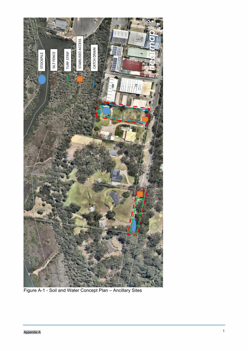
Figure A-1 - Soil and Water Concept Plan – Ancillary Sites
-0.0
0.5
0.5
1.0
1.0
1.5
1.5
1.51.5
1.5
1.5
1.5
2.0 2.0
2.0
2.0 2.02.0
2.0
2.0
2.0
2.0
2.0
2.0
2.0
2.0
2.0
2.0
2.0
2.0
2.0
2.02.0
2.5
2.5
2.5
2.5
2.5
2.5
2.5
2.5
2.5
2.5
2.5
2.5
2.5
F
L
F
L
FL
FL
FL
FL
IN
3
7
5
D
ia
IN
3
7
5
D
ia
IN
3
7
5
D
ia
IN
375 D
ia
IN
3
7
5
D
ia
IN
3
7
5
D
ia
IN
3
7
5
D
ia
IN
375 D
ia
IN
5
2
5
D
ia
IN
7
5
0
D
ia
IN
750 D
ia
IN
750 D
ia
IN
IN
IN
IN
IN
IN
IN
IN
IN
IN
IN
EP
EP
E
P
E
P
X
X
X
XXXXXXXX
XX
X X X X X X X X X X
X
X
X
XXXXXXXX
XX
X X X X X X X X X X
EMPIRE BAY DRIVE MR349
SUND
OWNE
R AV
ENUE
LOT 500DP823145
LOT 25DP240878
LOT 30DP240878
LOT 29DP240878
LOT 28DP240878
LOT 27DP240878
LOT 26DP240878
MC02
MC01
TC 209.371
CT 240.860
180 200 220 240 260 280 300
TC 62.255 CT 117.775
40 60 80 100 120
140
160
180
DESIGN
DESIGN CHECK
DRAWN
DRG CHECK
DESIGN MNGR
PROJECT MNGRISSUE STATUS SHEET No. ISSUE
RMS REGISTRATION No. PART
EDMS No.
REV DATE AMENDMENT / REVISION DESCRIPTION APPROVAL
A3SCALES ON A3 SIZE DRAWING
3540
4550
mm O
N A3
SIZ
E OR
IGIN
AL
THIS
DRA
WIN
G MA
Y BE
PRE
PARE
D IN
COL
OUR
AND
MAY
BE IN
COMP
LETE
IF C
OPIE
D
PREPARED FOR
DESIGN MODEL FILE(S) USED FOR DOCUMENTATION OF THIS DRAWING
DRAWINGS / DESIGN PREPARED BY TITLE NAME
© Roads and Maritime Services
NOT FOR CONSTRUCTIONPLOT DATE / TIME PLOT BY
DATE
DESIGN LOT CODE
EXTERNAL REFERENCE FILES WVR No.
DRAWING FILE LOCATION / NAME
CO-ORDINATE SYSTEM HEIGHT DATUM
CLIENT
05
1015
2025
30
F:\17-491 EBD Intersection\Drgs\Civil\Final\SM-240.dwg SM-240.dwg 2/13/2018 11:47 AM Tadhg Stephens
X_G
E-SH
T-A3
X_G
E-TX
T-KE
Y-PL
AN-5
SHTS
-SM
X_G
E-XB
ASE-
EROS
ION
X_S
U-SU
RVEY
X_G
E-TX
T-RO
AD-L
OT-L
ABEL
S X
_GE-
TXT-
SHEE
T-FR
AMES
X_R
D_DE
SIGN
X_R
D-CO
NTRO
L-MA
STER
X_S
U-BO
UNDA
RY_P
ROPO
SED
X_S
M-ST
ORMW
ATER
X_R
D_CO
NTOU
RS_D
ESIG
N X
_SU-
CONT
OURS
-EXI
STIN
G X
_GE-
TXT-
DRAI
NAGE
X_S
M-SE
D-ER
OSIO
N X
_GE-
TXT-
EROS
ION-
LEGE
ND
Civil Engineers and Project Managers
02 9923 1055
02 9439 1777
Level 7, 153 Walker Street
North Sydney NSW 2060
Tel:
Fax:
ABN 96 130 882 405
www.atl.net.au
TECHNICAL AND PROJECT SERVICESGREATER SYDNEY PROGRAM OFFICEGREATER SYDNEY - SYDNEY OUTER
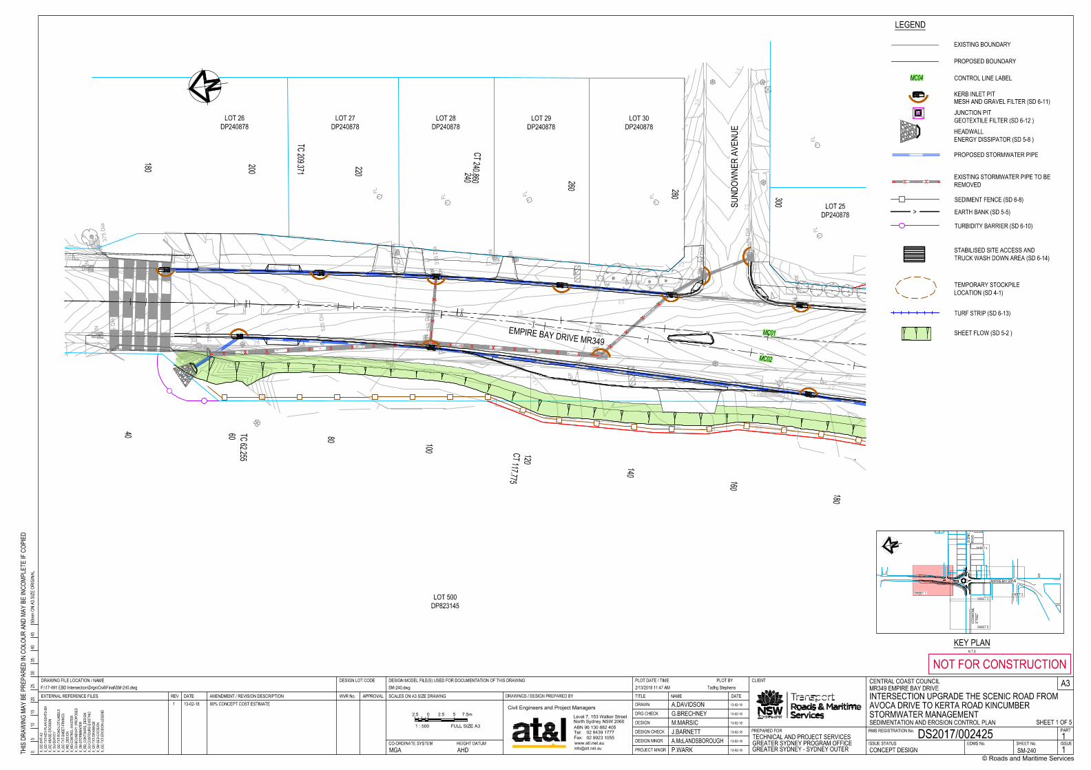
CENTRAL COAST COUNCILMR349 EMPIRE BAY DRIVEINTERSECTION UPGRADE THE SCENIC ROAD FROM AVOCA DRIVE TO KERTA ROAD KINCUMBERSTORMWATER MANAGEMENTSEDIMENTATION AND EROSION CONTROL PLAN
DS2017/002425CONCEPT DESIGN SM-240 1
1
A.DAVIDSON 13-02-18
G.BRECHNEY 13-02-18
M.MARSICJ.BARNETTA.McLANDSBOROUGHP.WARK
13-02-18
13-02-18
13-02-18
13-02-18MGA AHD
1 13-02-18 80% CONCEPT COST ESTIMATE
SHEET 1 OF 52.5 0 5 7.5m2.5
1 : 500 FULL SIZE A3
EMPIRE BAY DRIVE
KEY PLANN.T.S
COCH
RONE
STRE
ET
SCEN
ICRO
AD
SHEET 4
SHEET 1 SHEET 3
SHEET 5
SHEET 2
LEGEND
EXISTING BOUNDARY
PROPOSED BOUNDARY
MC04 CONTROL LINE LABEL
PROPOSED STORMWATER PIPE
KERB INLET PIT
JUNCTION PITGEOTEXTILE FILTER (SD 6-12 )HEADWALLENERGY DISSIPATOR (SD 5-8 )
XX EXISTING STORMWATER PIPE TO BEREMOVED
SEDIMENT FENCE (SD 6-8)
> EARTH BANK (SD 5-5)
STABILISED SITE ACCESS ANDTRUCK WASH DOWN AREA (SD 6-14)
TURBIDITY BARRIER (SD 6-10)
TEMPORARY STOCKPILELOCATION (SD 4-1)
TURF STRIP (SD 6-13)
MESH AND GRAVEL FILTER (SD 6-11)
SHEET FLOW (SD 5-2 )
2.5
2.5
2.5
2.5
2.5
2.5
2.5
2.52.5
2.5
2.5
3.03.0
3.03.0
3.0
3.0
3.03.0
3.0
3.0
3.5
3.5
3.5
3.5
3.5
3.5
3.53.5
3.5
4.0
4.0
4.0
4.0
4.0
4.0
4.0
4.0
4.0
4.04.0
4.54.5
4.5
4.5
4.5
4.5
4.5
4.5
5.0
5.0
5.0
5.0
5.0
5.0
5.5
FL
FL
F
L
F
L
FL
FL
FL
FL
F
L
FL
FL
F
L
FL
FL
FL
FL
F
L
IN
3
0
0
D
ia
IN
3
0
0
D
ia
IN
3
7
5
D
ia
IN
375 D
ia
IN
3
7
5
D
ia
IN
3
7
5
D
ia
IN
3
7
5
D
ia
IN
3
7
5
D
ia
IN
375 D
ia
IN
3
7
5
D
ia
IN
3
7
5
D
ia
IN
4
5
0
D
ia
IN
4
5
0
D
ia
IN
4
5
0
D
ia
IN
4
5
0
D
ia
IN
5
2
5
D
ia
IN
5
2
5
D
ia
IN
5
2
5
D
ia
IN
525 D
ia
IN
600 D
ia
IN
IN
IN
IN
IN
IN
IN
IN
IN
IN
ININ
IN
IN
IN
JB
E
P
E
P
E
P
E
P
E
P
G
P
XX
XX
XX
XX
COCHRONESTREET
EMPIRE BAY DRIVE MR349
LOT 500DP823145
SP74110LOT 1DP504017
LOT 26DP1092431
SP81546
LOT 21DP1009451
LOT 1DP1214826
LOT 22DP1009451
LOT 1DP240878
LOT 25DP240878
MC06
MC05
MC02
MC01
MC03
MC04
TC 319.927
CTP 355.526
CTP 363.887
CTP 406.139
CT 438.442
TC 451.441
320
340
360
380
400 420 440
460
TC 197.668
CTP 220.760
CTP 228.383
CTP 260.894
CT 301.697
180
200
220
240
260 280 300
320
0.000
46.090
20
40
0.000
TC 31.500
CT 61.339
70.060
20
40
60
CTP 65.223
91.351
60
80
59.528
40DESIGN
DESIGN CHECK
DRAWN
DRG CHECK
DESIGN MNGR
PROJECT MNGRISSUE STATUS SHEET No. ISSUE
RMS REGISTRATION No. PART
EDMS No.
REV DATE AMENDMENT / REVISION DESCRIPTION APPROVAL
A3SCALES ON A3 SIZE DRAWING
3540
4550
mm O
N A3
SIZ
E OR
IGIN
AL
THIS
DRA
WIN
G MA
Y BE
PRE
PARE
D IN
COL
OUR
AND
MAY
BE IN
COMP
LETE
IF C
OPIE
D
PREPARED FOR
DESIGN MODEL FILE(S) USED FOR DOCUMENTATION OF THIS DRAWING
DRAWINGS / DESIGN PREPARED BY TITLE NAME
© Roads and Maritime Services
NOT FOR CONSTRUCTIONPLOT DATE / TIME PLOT BY
DATE
DESIGN LOT CODE
EXTERNAL REFERENCE FILES WVR No.
DRAWING FILE LOCATION / NAME
CO-ORDINATE SYSTEM HEIGHT DATUM
CLIENT
05
1015
2025
30
F:\17-491 EBD Intersection\Drgs\Civil\Final\SM-241.dwg SM-241.dwg 2/20/2018 2:56 PM Tadhg Stephens
X_G
E-SH
T-A3
X_G
E-TX
T-KE
Y-PL
AN-5
SHTS
-SM
X_G
E-XB
ASE-
EROS
ION
X_S
U-SU
RVEY
X_G
E-TX
T-RO
AD-L
OT-L
ABEL
S X
_GE-
TXT-
SHEE
T-FR
AMES
X_R
D_DE
SIGN
X_R
D-CO
NTRO
L-MA
STER
X_S
U-BO
UNDA
RY_P
ROPO
SED
X_S
M-ST
ORMW
ATER
X_R
D_CO
NTOU
RS_D
ESIG
N X
_SU-
CONT
OURS
-EXI
STIN
G X
_GE-
TXT-
DRAI
NAGE
X_S
M-SE
D-ER
OSIO
N X
_GE-
TXT-
EROS
ION-
LEGE
ND
Civil Engineers and Project Managers
02 9923 1055
02 9439 1777
Level 7, 153 Walker Street
North Sydney NSW 2060
Tel:
Fax:
ABN 96 130 882 405
www.atl.net.au
TECHNICAL AND PROJECT SERVICESGREATER SYDNEY PROGRAM OFFICEGREATER SYDNEY - SYDNEY OUTER
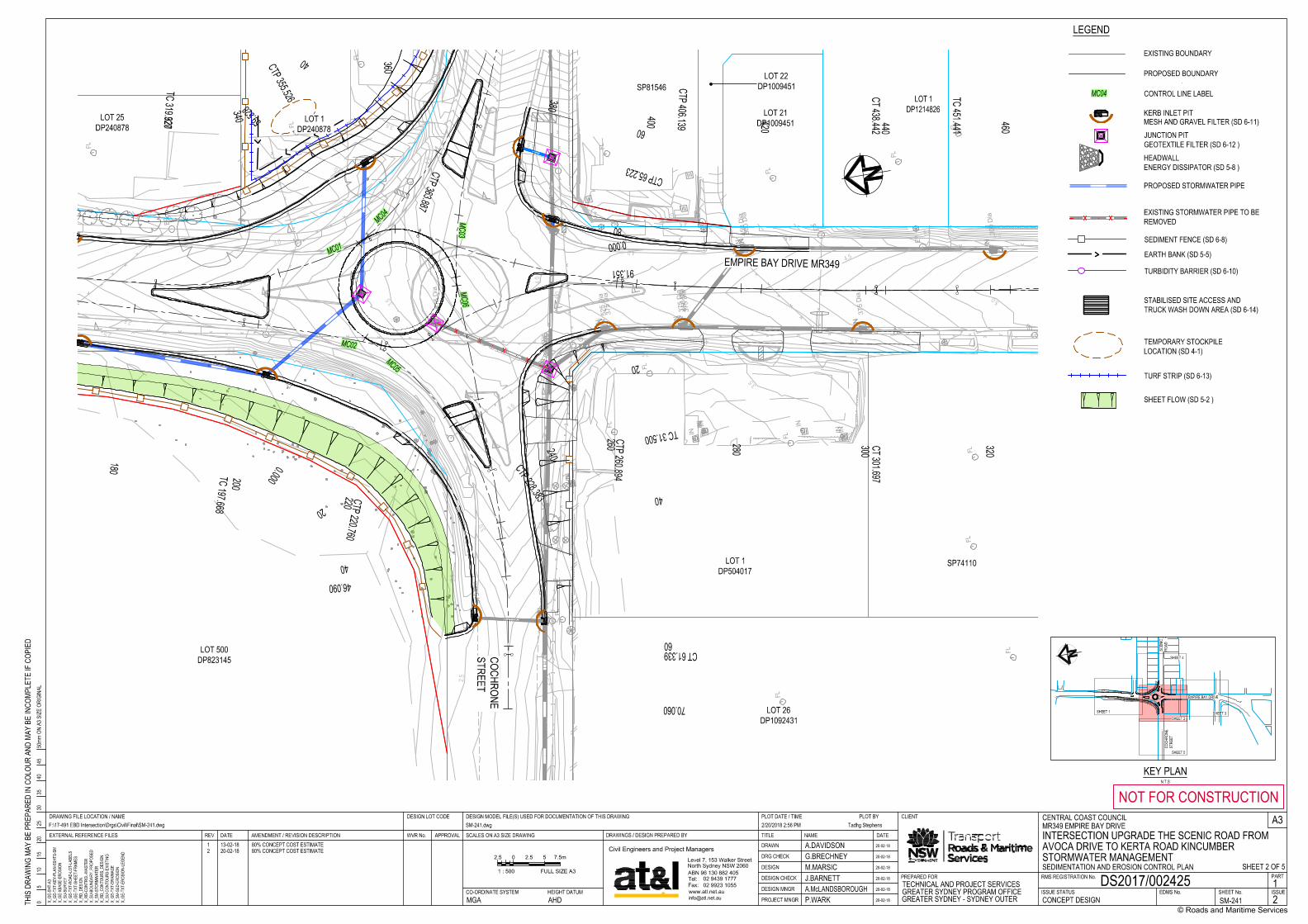
CENTRAL COAST COUNCILMR349 EMPIRE BAY DRIVEINTERSECTION UPGRADE THE SCENIC ROAD FROM AVOCA DRIVE TO KERTA ROAD KINCUMBERSTORMWATER MANAGEMENTSEDIMENTATION AND EROSION CONTROL PLAN
DS2017/002425CONCEPT DESIGN SM-241 2
1
A.DAVIDSON 20-02-18
G.BRECHNEY 20-02-18
M.MARSICJ.BARNETTA.McLANDSBOROUGHP.WARK
20-02-18
20-02-18
20-02-18
20-02-18MGA AHD
1 13-02-18 80% CONCEPT COST ESTIMATE2 20-02-18 80% CONCEPT COST ESTIMATE
SHEET 2 OF 52.5 0 5 7.5m2.5
1 : 500 FULL SIZE A3
EMPIRE BAY DRIVE
KEY PLANN.T.S
COCH
RONE
STRE
ET
SCEN
ICRO
AD
SHEET 4
SHEET 1 SHEET 3
SHEET 5
SHEET 2
LEGEND
EXISTING BOUNDARY
PROPOSED BOUNDARY
MC04 CONTROL LINE LABEL
PROPOSED STORMWATER PIPE
KERB INLET PIT
JUNCTION PITGEOTEXTILE FILTER (SD 6-12 )HEADWALLENERGY DISSIPATOR (SD 5-8 )
EXISTING STORMWATER PIPE TO BEREMOVED
SEDIMENT FENCE (SD 6-8)
EARTH BANK (SD 5-5)
STABILISED SITE ACCESS ANDTRUCK WASH DOWN AREA (SD 6-14)
TURBIDITY BARRIER (SD 6-10)
TEMPORARY STOCKPILELOCATION (SD 4-1)
TURF STRIP (SD 6-13)
MESH AND GRAVEL FILTER (SD 6-11)
SHEET FLOW (SD 5-2 )
4.0
4.0
4.0
4.54.5
4.5
5.0
5.05.0
5.0
5.0
5.0
5.0
5.5
5.5
5.55.55.5
5.5
5.5
5.55.5
5.5
5.5
5.5 5.5
6.0 6.0 6.0 6.0
6.0
6.0
6.0
6.0
6.0 6.0
6.0
6.5
6.5
6.5
6.5
6.5
7.0
7.0
7.5
FL
F
L
FL
FL
F
L
FL
FL
TC
T
D
P
A
JP
TS
P
IN
3
0
0
D
ia
IN
3
7
5
D
ia
IN
3
7
5
D
ia
IN
4
5
0
D
ia
IN
6
0
0
D
ia
IN
6
0
0
D
ia
IN
6
0
0
D
ia
IN
6
0
0
D
ia
IN
6
0
0
D
ia
IN
IN
IN
JB
JB
JB
E
M
H
EP
E
P
E
P
E
P
E
P
E
P
EP
E
P
E
P
H
P
B
P
BP
B
P
D
H
D
H
D
H
D
H
D
H
D
H
D
H
PI
P
I
PI
?P
?
?
?
?
?
W
RW
H
W
H
W
H
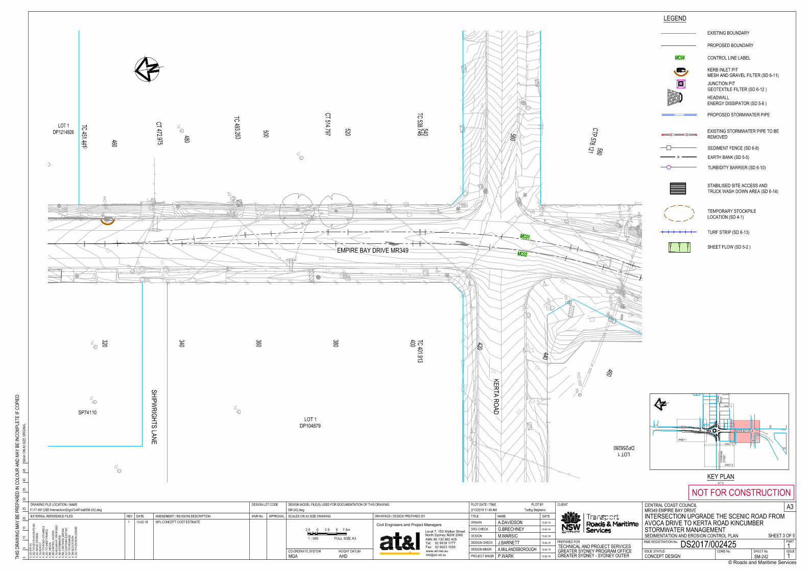
EMPIRE BAY DRIVE MR349
KERTA ROAD
SHIPWRIGHTS LANE
LOT 1DP258280
LOT 1DP104879
SP74110
LOT 1DP1214826
MC01
MC02
TC 451.441
CT 472.975
TC 493.263
CT 514.797
TC 538.746
CTP 578.121
460
480
500
520
540 560
580
TC 401.913
320
340
360
380
400 420
440
460
DESIGN
DESIGN CHECK
DRAWN
DRG CHECK
DESIGN MNGR
PROJECT MNGRISSUE STATUS SHEET No. ISSUE
RMS REGISTRATION No. PART
EDMS No.
REV DATE AMENDMENT / REVISION DESCRIPTION APPROVAL
A3SCALES ON A3 SIZE DRAWING
3540
4550
mm O
N A3
SIZ
E OR
IGIN
AL
THIS
DRA
WIN
G MA
Y BE
PRE
PARE
D IN
COL
OUR
AND
MAY
BE IN
COMP
LETE
IF C
OPIE
D
PREPARED FOR
DESIGN MODEL FILE(S) USED FOR DOCUMENTATION OF THIS DRAWING
DRAWINGS / DESIGN PREPARED BY TITLE NAME
© Roads and Maritime Services
NOT FOR CONSTRUCTIONPLOT DATE / TIME PLOT BY
DATE
DESIGN LOT CODE
EXTERNAL REFERENCE FILES WVR No.
DRAWING FILE LOCATION / NAME
CO-ORDINATE SYSTEM HEIGHT DATUM
CLIENT
05
1015
2025
30
F:\17-491 EBD Intersection\Drgs\Civil\Final\SM-242.dwg SM-242.dwg 2/13/2018 11:48 AM Tadhg Stephens
X_G
E-SH
T-A3
X_G
E-TX
T-KE
Y-PL
AN-5
SHTS
-SM
X_G
E-XB
ASE-
EROS
ION
X_S
U-SU
RVEY
X_G
E-TX
T-RO
AD-L
OT-L
ABEL
S X
_GE-
TXT-
SHEE
T-FR
AMES
X_R
D_DE
SIGN
X_R
D-CO
NTRO
L-MA
STER
X_S
U-BO
UNDA
RY_P
ROPO
SED
X_S
M-ST
ORMW
ATER
X_R
D_CO
NTOU
RS_D
ESIG
N X
_SU-
CONT
OURS
-EXI
STIN
G X
_GE-
TXT-
DRAI
NAGE
X_S
M-SE
D-ER
OSIO
N X
_GE-
TXT-
EROS
ION-
LEGE
ND
Civil Engineers and Project Managers
02 9923 1055
02 9439 1777
Level 7, 153 Walker Street
North Sydney NSW 2060
Tel:
Fax:
ABN 96 130 882 405
www.atl.net.au
TECHNICAL AND PROJECT SERVICESGREATER SYDNEY PROGRAM OFFICEGREATER SYDNEY - SYDNEY OUTER
CENTRAL COAST COUNCILMR349 EMPIRE BAY DRIVEINTERSECTION UPGRADE THE SCENIC ROAD FROM AVOCA DRIVE TO KERTA ROAD KINCUMBERSTORMWATER MANAGEMENTSEDIMENTATION AND EROSION CONTROL PLAN
DS2017/002425CONCEPT DESIGN SM-242 1
1
A.DAVIDSON 13-02-18
G.BRECHNEY 13-02-18
M.MARSICJ.BARNETTA.McLANDSBOROUGHP.WARK
13-02-18
13-02-18
13-02-18
13-02-18MGA AHD
1 13-02-18 80% CONCEPT COST ESTIMATE
SHEET 3 OF 52.5 0 5 7.5m2.5
1 : 500 FULL SIZE A3
EMPIRE BAY DRIVE
KEY PLANN.T.S
COCH
RONE
STRE
ET
SCEN
ICRO
AD
SHEET 4
SHEET 1 SHEET 3
SHEET 5
SHEET 2
LEGEND
EXISTING BOUNDARY
PROPOSED BOUNDARY
MC04 CONTROL LINE LABEL
PROPOSED STORMWATER PIPE
KERB INLET PIT
JUNCTION PITGEOTEXTILE FILTER (SD 6-12 )HEADWALLENERGY DISSIPATOR (SD 5-8 )
XX EXISTING STORMWATER PIPE TO BEREMOVED
SEDIMENT FENCE (SD 6-8)
> EARTH BANK (SD 5-5)
STABILISED SITE ACCESS ANDTRUCK WASH DOWN AREA (SD 6-14)
TURBIDITY BARRIER (SD 6-10)
TEMPORARY STOCKPILELOCATION (SD 4-1)
TURF STRIP (SD 6-13)
MESH AND GRAVEL FILTER (SD 6-11)
SHEET FLOW (SD 5-2 )
3.5
4.0
4.0
4.5
4.5
4.5
4.5
5.0
5.0
5.0
5.5
5.5
5.5
6.0
6.0
6.0
6.5
6.5
6.5
7.0
7.0
7.0
7.57.5
7.5
8.08.0
8.08.5
8.5
8.5
9.0
9.0
9.0
9.5
9.5
10.0
10.0
10.5
10.5
11.0
11.0
11.5
11.5
12.0
12.0
12.5
12.5
13.0
13.5
14.0
FL
FL
F
L
F
L
F
L
F
L
FL
F
L
F
L
IN
3
7
5
D
ia
IN
3
7
5
D
ia
IN
375 D
ia
IN
IN
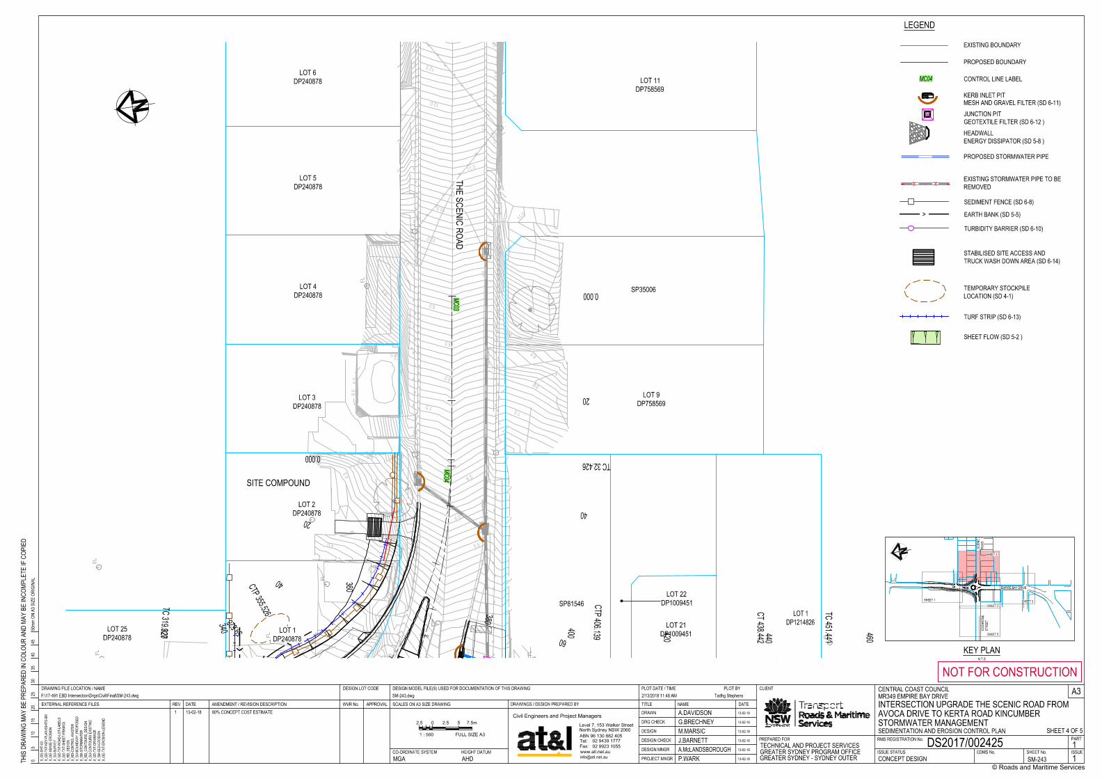
SITE COMPOUND
THE SCENIC ROAD
SP81546
LOT 21DP1009451
LOT 1DP1214826
LOT 22DP1009451
LOT 1DP240878
LOT 2DP240878
LOT 25DP240878
LOT 3DP240878
LOT 4DP240878
LOT 5DP240878
LOT 6DP240878
LOT 9DP758569
SP35006
LOT 11DP758569
MC04MC03
TC 319.927
CTP 355.526
CTP 406.139
CT 438.442
TC 451.441
300 320
340
360
380
400 420 440
460
0.000
TC 32.426
20
40
60
0.000
59.528
20
40
DESIGN
DESIGN CHECK
DRAWN
DRG CHECK
DESIGN MNGR
PROJECT MNGRISSUE STATUS SHEET No. ISSUE
RMS REGISTRATION No. PART
EDMS No.
REV DATE AMENDMENT / REVISION DESCRIPTION APPROVAL
A3SCALES ON A3 SIZE DRAWING
3540
4550
mm O
N A3
SIZ
E OR
IGIN
AL
THIS
DRA
WIN
G MA
Y BE
PRE
PARE
D IN
COL
OUR
AND
MAY
BE IN
COMP
LETE
IF C
OPIE
D
PREPARED FOR
DESIGN MODEL FILE(S) USED FOR DOCUMENTATION OF THIS DRAWING
DRAWINGS / DESIGN PREPARED BY TITLE NAME
© Roads and Maritime Services
NOT FOR CONSTRUCTIONPLOT DATE / TIME PLOT BY
DATE
DESIGN LOT CODE
EXTERNAL REFERENCE FILES WVR No.
DRAWING FILE LOCATION / NAME
CO-ORDINATE SYSTEM HEIGHT DATUM
CLIENT
05
1015
2025
30
F:\17-491 EBD Intersection\Drgs\Civil\Final\SM-243.dwg SM-243.dwg 2/13/2018 11:48 AM Tadhg Stephens
X_G
E-SH
T-A3
X_G
E-TX
T-KE
Y-PL
AN-5
SHTS
-SM
X_G
E-XB
ASE-
EROS
ION
X_S
U-SU
RVEY
X_G
E-TX
T-RO
AD-L
OT-L
ABEL
S X
_GE-
TXT-
SHEE
T-FR
AMES
X_R
D_DE
SIGN
X_R
D-CO
NTRO
L-MA
STER
X_S
U-BO
UNDA
RY_P
ROPO
SED
X_S
M-ST
ORMW
ATER
X_R
D_CO
NTOU
RS_D
ESIG
N X
_SU-
CONT
OURS
-EXI
STIN
G X
_GE-
TXT-
DRAI
NAGE
X_S
M-SE
D-ER
OSIO
N X
_GE-
TXT-
EROS
ION-
LEGE
ND
Civil Engineers and Project Managers
02 9923 1055
02 9439 1777
Level 7, 153 Walker Street
North Sydney NSW 2060
Tel:
Fax:
ABN 96 130 882 405
www.atl.net.au
TECHNICAL AND PROJECT SERVICESGREATER SYDNEY PROGRAM OFFICEGREATER SYDNEY - SYDNEY OUTER
CENTRAL COAST COUNCILMR349 EMPIRE BAY DRIVEINTERSECTION UPGRADE THE SCENIC ROAD FROM AVOCA DRIVE TO KERTA ROAD KINCUMBERSTORMWATER MANAGEMENTSEDIMENTATION AND EROSION CONTROL PLAN
DS2017/002425CONCEPT DESIGN SM-243 1
1
A.DAVIDSON 13-02-18
G.BRECHNEY 13-02-18
M.MARSICJ.BARNETTA.McLANDSBOROUGHP.WARK
13-02-18
13-02-18
13-02-18
13-02-18MGA AHD
1 13-02-18 80% CONCEPT COST ESTIMATE
SHEET 4 OF 52.5 0 5 7.5m2.5
1 : 500 FULL SIZE A3
EMPIRE BAY DRIVE
KEY PLANN.T.S
COCH
RONE
STRE
ET
SCEN
ICRO
AD
SHEET 4
SHEET 1 SHEET 3
SHEET 5
SHEET 2
LEGEND
EXISTING BOUNDARY
PROPOSED BOUNDARY
MC04 CONTROL LINE LABEL
PROPOSED STORMWATER PIPE
KERB INLET PIT
JUNCTION PITGEOTEXTILE FILTER (SD 6-12 )HEADWALLENERGY DISSIPATOR (SD 5-8 )
XX EXISTING STORMWATER PIPE TO BEREMOVED
SEDIMENT FENCE (SD 6-8)
> EARTH BANK (SD 5-5)
STABILISED SITE ACCESS ANDTRUCK WASH DOWN AREA (SD 6-14)
TURBIDITY BARRIER (SD 6-10)
TEMPORARY STOCKPILELOCATION (SD 4-1)
TURF STRIP (SD 6-13)
MESH AND GRAVEL FILTER (SD 6-11)
SHEET FLOW (SD 5-2 )
0.5
0.5
0.5
0.51.0
1.0
1.0
1.5
1.5
1.5
1.5
1.5
2.02.0
2.0
2.0
2.0
2.0
2.02.0
2.0
2.0
2.5
2.5
2.52.5
2.52.5
2.5
2.52.5
2.5
2.5
FL
FL
FL
F
L
FL
IN
4
5
0
D
ia
IN
4
5
0
D
ia
IN
6
0
0
D
ia
IN
6
0
0
D
ia
IN
6
0
0
D
ia
IN
600 D
ia
IN
6
0
0
D
ia
IN
6
0
0
D
ia
IN
6
0
0
D
ia
IN
600 D
ia
IN
7
5
0
D
ia
IN
IN
IN
IN
/o6
0
0
E
P
D
H
D
H
W
R
W
H
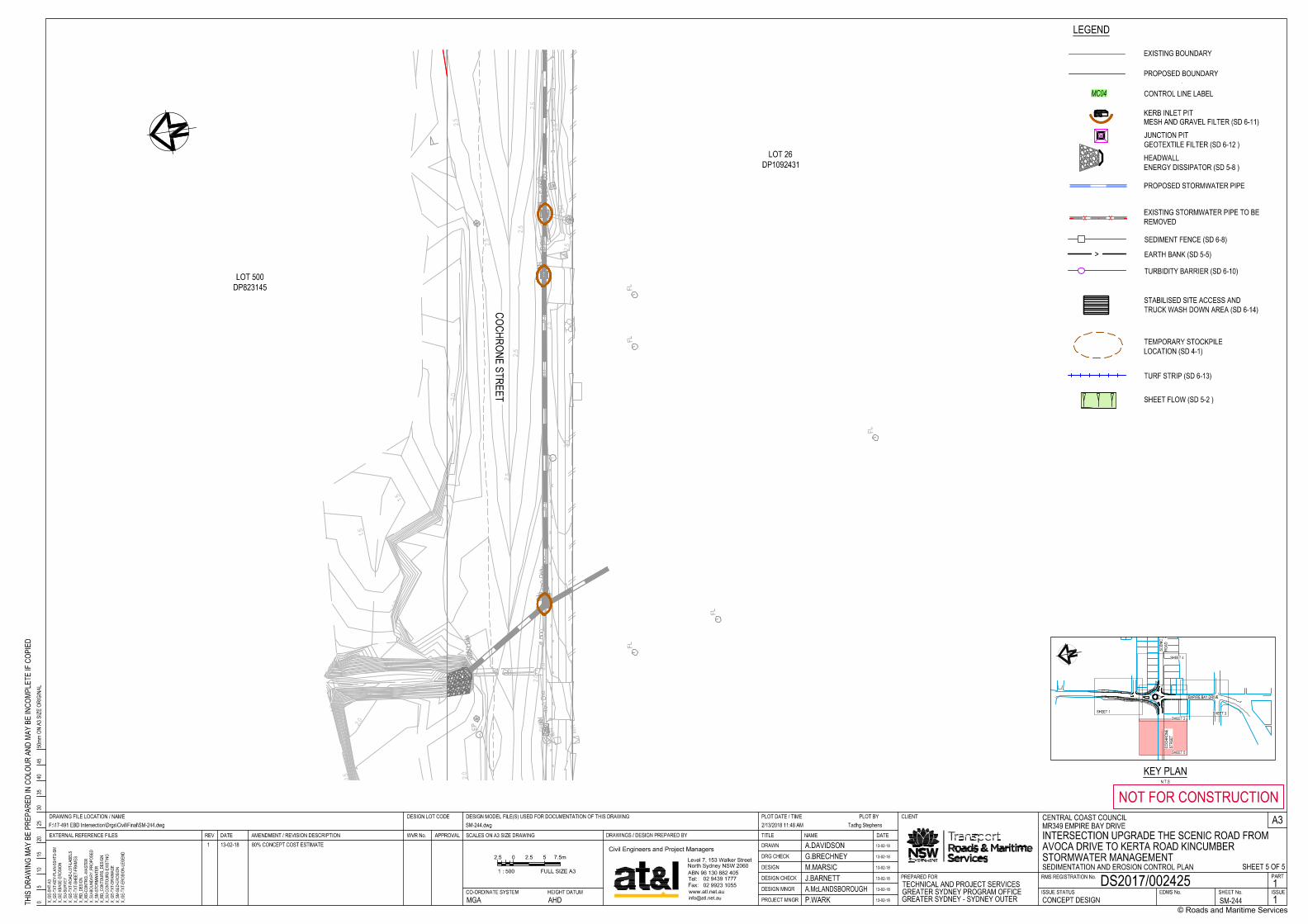
COCHRONE STREET
LOT 500DP823145
LOT 26DP1092431
DESIGN
DESIGN CHECK
DRAWN
DRG CHECK
DESIGN MNGR
PROJECT MNGRISSUE STATUS SHEET No. ISSUE
RMS REGISTRATION No. PART
EDMS No.
REV DATE AMENDMENT / REVISION DESCRIPTION APPROVAL
A3SCALES ON A3 SIZE DRAWING
3540
4550
mm O
N A3
SIZ
E OR
IGIN
AL
THIS
DRA
WIN
G MA
Y BE
PRE
PARE
D IN
COL
OUR
AND
MAY
BE IN
COMP
LETE
IF C
OPIE
D
PREPARED FOR
DESIGN MODEL FILE(S) USED FOR DOCUMENTATION OF THIS DRAWING
DRAWINGS / DESIGN PREPARED BY TITLE NAME
© Roads and Maritime Services
NOT FOR CONSTRUCTIONPLOT DATE / TIME PLOT BY
DATE
DESIGN LOT CODE
EXTERNAL REFERENCE FILES WVR No.
DRAWING FILE LOCATION / NAME
CO-ORDINATE SYSTEM HEIGHT DATUM
CLIENT
05
1015
2025
30
F:\17-491 EBD Intersection\Drgs\Civil\Final\SM-244.dwg SM-244.dwg 2/13/2018 11:48 AM Tadhg Stephens
X_G
E-SH
T-A3
X_G
E-TX
T-KE
Y-PL
AN-5
SHTS
-SM
X_G
E-XB
ASE-
EROS
ION
X_S
U-SU
RVEY
X_G
E-TX
T-RO
AD-L
OT-L
ABEL
S X
_GE-
TXT-
SHEE
T-FR
AMES
X_R
D_DE
SIGN
X_R
D-CO
NTRO
L-MA
STER
X_S
U-BO
UNDA
RY_P
ROPO
SED
X_S
M-ST
ORMW
ATER
X_R
D_CO
NTOU
RS_D
ESIG
N X
_SU-
CONT
OURS
-EXI
STIN
G X
_GE-
TXT-
DRAI
NAGE
X_S
M-SE
D-ER
OSIO
N X
_GE-
TXT-
EROS
ION-
LEGE
ND
Civil Engineers and Project Managers
02 9923 1055
02 9439 1777
Level 7, 153 Walker Street
North Sydney NSW 2060
Tel:
Fax:
ABN 96 130 882 405
www.atl.net.au
TECHNICAL AND PROJECT SERVICESGREATER SYDNEY PROGRAM OFFICEGREATER SYDNEY - SYDNEY OUTER
CENTRAL COAST COUNCILMR349 EMPIRE BAY DRIVEINTERSECTION UPGRADE THE SCENIC ROAD FROM AVOCA DRIVE TO KERTA ROAD KINCUMBERSTORMWATER MANAGEMENTSEDIMENTATION AND EROSION CONTROL PLAN
DS2017/002425CONCEPT DESIGN SM-244 1
1
A.DAVIDSON 13-02-18
G.BRECHNEY 13-02-18
M.MARSICJ.BARNETTA.McLANDSBOROUGHP.WARK
13-02-18
13-02-18
13-02-18
13-02-18MGA AHD
1 13-02-18 80% CONCEPT COST ESTIMATE
SHEET 5 OF 52.5 0 5 7.5m2.5
1 : 500 FULL SIZE A3
EMPIRE BAY DRIVE
KEY PLANN.T.S
COCH
RONE
STRE
ET
SCEN
ICRO
AD
SHEET 4
SHEET 1 SHEET 3
SHEET 5
SHEET 2
LEGEND
EXISTING BOUNDARY
PROPOSED BOUNDARY
MC04 CONTROL LINE LABEL
PROPOSED STORMWATER PIPE
KERB INLET PIT
JUNCTION PITGEOTEXTILE FILTER (SD 6-12 )HEADWALLENERGY DISSIPATOR (SD 5-8 )
XX EXISTING STORMWATER PIPE TO BEREMOVED
SEDIMENT FENCE (SD 6-8)
> EARTH BANK (SD 5-5)
STABILISED SITE ACCESS ANDTRUCK WASH DOWN AREA (SD 6-14)
TURBIDITY BARRIER (SD 6-10)
TEMPORARY STOCKPILELOCATION (SD 4-1)
TURF STRIP (SD 6-13)
MESH AND GRAVEL FILTER (SD 6-11)
SHEET FLOW (SD 5-2 )
DESIGN
DESIGN CHECK
DRAWN
DRG CHECK
DESIGN MNGR
PROJECT MNGRISSUE STATUS SHEET No. ISSUE
RMS REGISTRATION No. PART
EDMS No.
REV DATE AMENDMENT / REVISION DESCRIPTION APPROVAL
A3SCALES ON A3 SIZE DRAWING
3540
4550
mm O
N A3
SIZ
E OR
IGIN
AL
THIS
DRA
WIN
G MA
Y BE
PRE
PARE
D IN
COL
OUR
AND
MAY
BE IN
COMP
LETE
IF C
OPIE
D
PREPARED FOR
DESIGN MODEL FILE(S) USED FOR DOCUMENTATION OF THIS DRAWING
DRAWINGS / DESIGN PREPARED BY TITLE NAME
© Roads and Maritime Services
NOT FOR CONSTRUCTIONPLOT DATE / TIME PLOT BY
DATE
DESIGN LOT CODE
EXTERNAL REFERENCE FILES WVR No.
DRAWING FILE LOCATION / NAME
CO-ORDINATE SYSTEM HEIGHT DATUM
CLIENT
05
1015
2025
30
F:\17-491 EBD Intersection\Drgs\Civil\Final\SM-245.dwg SM-245.dwg 2/13/2018 11:48 AM Tadhg Stephens
X_G
E-SH
T-A3
Logo
Civil Engineers and Project Managers
02 9923 1055
02 9439 1777
Level 7, 153 Walker Street
North Sydney NSW 2060
Tel:
Fax:
ABN 96 130 882 405
www.atl.net.au
TECHNICAL AND PROJECT SERVICESGREATER SYDNEY PROGRAM OFFICEGREATER SYDNEY - SYDNEY OUTER
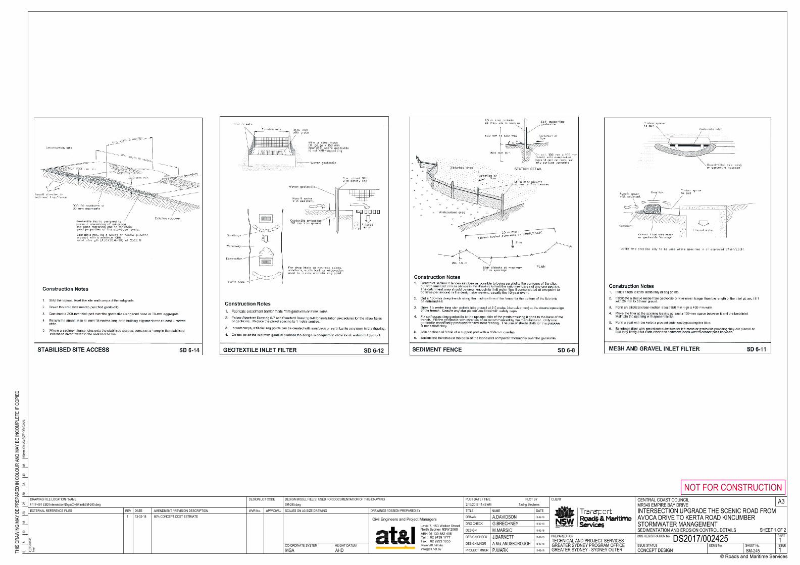
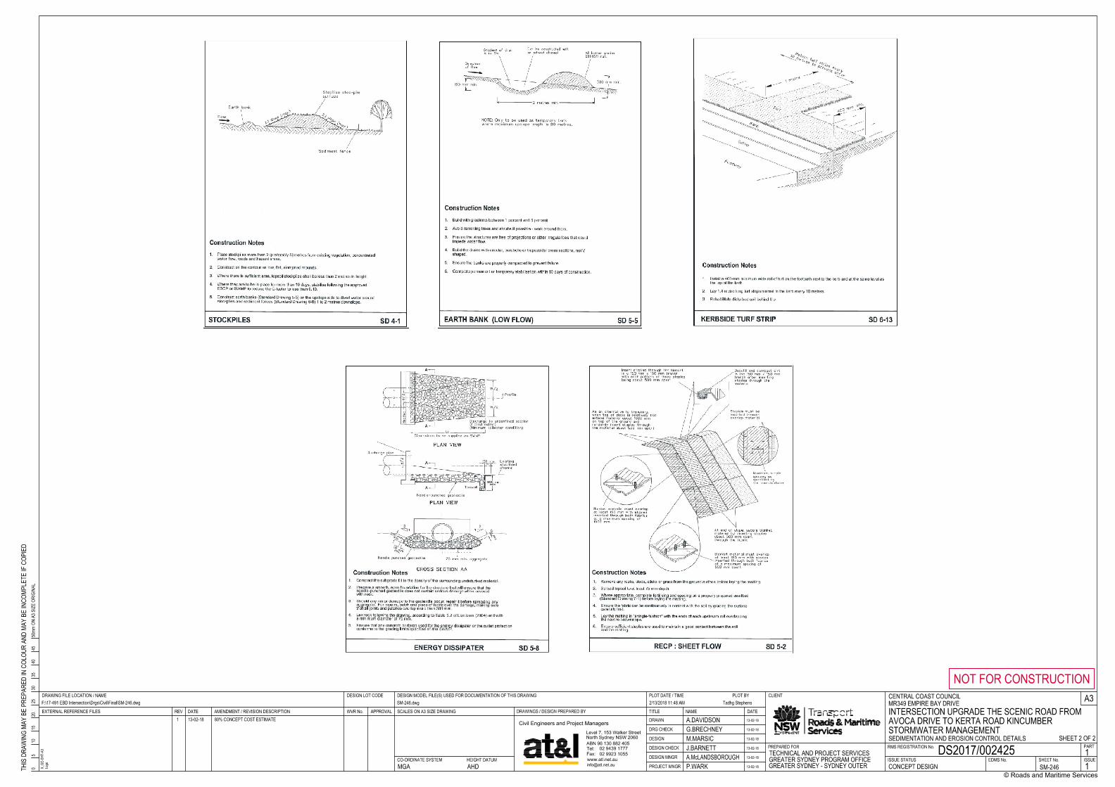
CENTRAL COAST COUNCILMR349 EMPIRE BAY DRIVEINTERSECTION UPGRADE THE SCENIC ROAD FROM AVOCA DRIVE TO KERTA ROAD KINCUMBERSTORMWATER MANAGEMENTSEDIMENTATION AND EROSION CONTROL DETAILS
DS2017/002425CONCEPT DESIGN SM-245 1
1
A.DAVIDSON 13-02-18
G.BRECHNEY 13-02-18
M.MARSICJ.BARNETTA.McLANDSBOROUGHP.WARK
13-02-18
13-02-18
13-02-18
13-02-18MGA AHD
1 13-02-18 80% CONCEPT COST ESTIMATE
SHEET 1 OF 2
DESIGN
DESIGN CHECK
DRAWN
DRG CHECK
DESIGN MNGR
PROJECT MNGRISSUE STATUS SHEET No. ISSUE
RMS REGISTRATION No. PART
EDMS No.
REV DATE AMENDMENT / REVISION DESCRIPTION APPROVAL
A3SCALES ON A3 SIZE DRAWING
3540
4550
mm O
N A3
SIZ
E OR
IGIN
AL
THIS
DRA
WIN
G MA
Y BE
PRE
PARE
D IN
COL
OUR
AND
MAY
BE IN
COMP
LETE
IF C
OPIE
D
PREPARED FOR
DESIGN MODEL FILE(S) USED FOR DOCUMENTATION OF THIS DRAWING
DRAWINGS / DESIGN PREPARED BY TITLE NAME
© Roads and Maritime Services
NOT FOR CONSTRUCTIONPLOT DATE / TIME PLOT BY
DATE
DESIGN LOT CODE
EXTERNAL REFERENCE FILES WVR No.
DRAWING FILE LOCATION / NAME
CO-ORDINATE SYSTEM HEIGHT DATUM
CLIENT
05
1015
2025
30
F:\17-491 EBD Intersection\Drgs\Civil\Final\SM-246.dwg SM-246.dwg 2/13/2018 11:48 AM Tadhg Stephens
X_G
E-SH
T-A3
Logo
Civil Engineers and Project Managers
02 9923 1055
02 9439 1777
Level 7, 153 Walker Street
North Sydney NSW 2060
Tel:
Fax:
ABN 96 130 882 405
www.atl.net.au
TECHNICAL AND PROJECT SERVICESGREATER SYDNEY PROGRAM OFFICEGREATER SYDNEY - SYDNEY OUTER
CENTRAL COAST COUNCILMR349 EMPIRE BAY DRIVEINTERSECTION UPGRADE THE SCENIC ROAD FROM AVOCA DRIVE TO KERTA ROAD KINCUMBERSTORMWATER MANAGEMENTSEDIMENTATION AND EROSION CONTROL DETAILS
DS2017/002425CONCEPT DESIGN SM-246 1
1
A.DAVIDSON 13-02-18
G.BRECHNEY 13-02-18
M.MARSICJ.BARNETTA.McLANDSBOROUGHP.WARK
13-02-18
13-02-18
13-02-18
13-02-18MGA AHD
1 13-02-18 80% CONCEPT COST ESTIMATE
SHEET 2 OF 2
Appendix [XX] 1
Appendix B
Unexpected Discovery of Contaminated Material Procedure
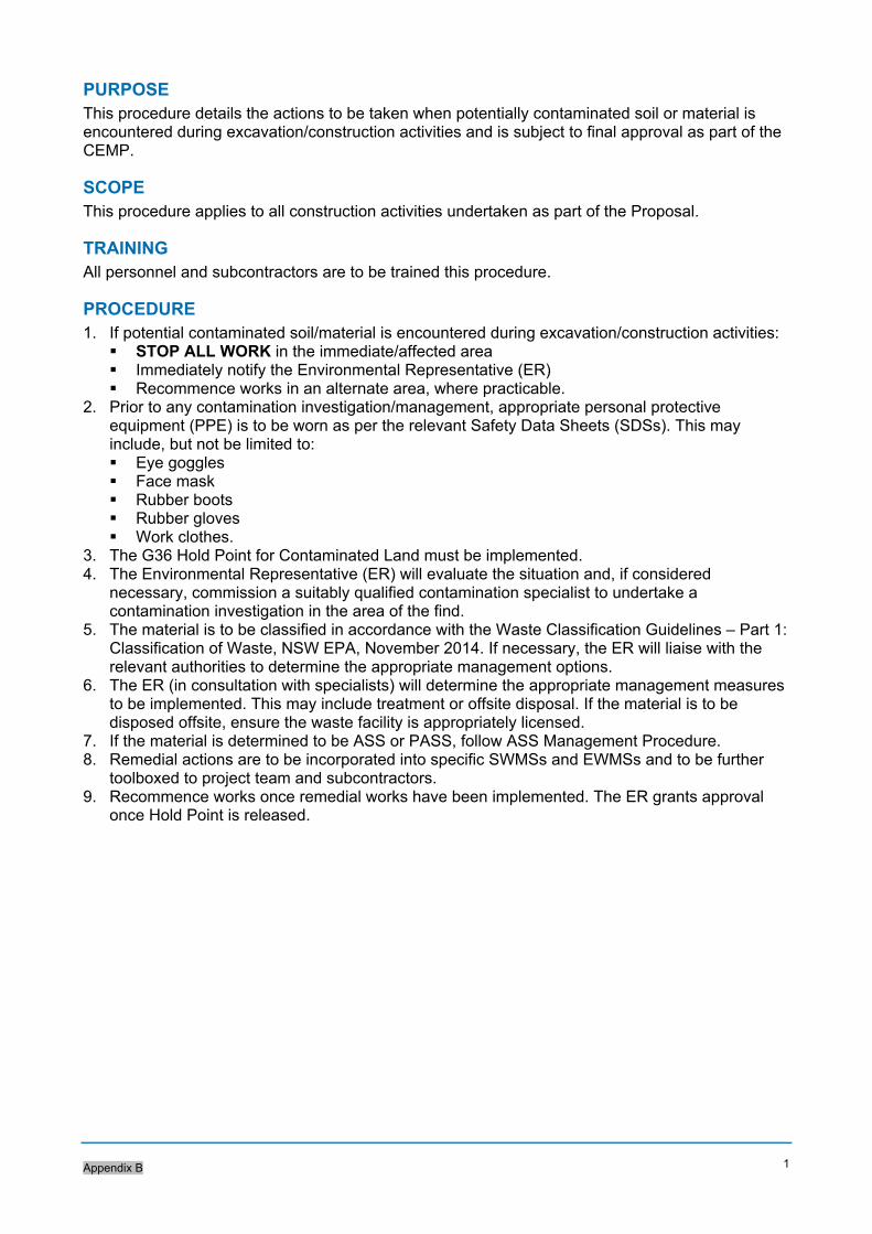
Appendix B
1
PURPOSE This procedure details the actions to be taken when potentially contaminated soil or material is encountered during excavation/construction activities and is subject to final approval as part of the CEMP.
SCOPE This procedure applies to all construction activities undertaken as part of the Proposal.
TRAINING All personnel and subcontractors are to be trained this procedure.
PROCEDURE 1. If potential contaminated soil/material is encountered during excavation/construction activities: STOP ALL WORK in the immediate/affected area Immediately notify the Environmental Representative (ER) Recommence works in an alternate area, where practicable.
2. Prior to any contamination investigation/management, appropriate personal protective equipment (PPE) is to be worn as per the relevant Safety Data Sheets (SDSs). This may include, but not be limited to: Eye goggles Face mask Rubber boots Rubber gloves Work clothes.
3. The G36 Hold Point for Contaminated Land must be implemented. 4. The Environmental Representative (ER) will evaluate the situation and, if considered
necessary, commission a suitably qualified contamination specialist to undertake a contamination investigation in the area of the find.
5. The material is to be classified in accordance with the Waste Classification Guidelines – Part 1: Classification of Waste, NSW EPA, November 2014. If necessary, the ER will liaise with the relevant authorities to determine the appropriate management options.
6. The ER (in consultation with specialists) will determine the appropriate management measures to be implemented. This may include treatment or offsite disposal. If the material is to be disposed offsite, ensure the waste facility is appropriately licensed.
7. If the material is determined to be ASS or PASS, follow ASS Management Procedure. 8. Remedial actions are to be incorporated into specific SWMSs and EWMSs and to be further
toolboxed to project team and subcontractors. 9. Recommence works once remedial works have been implemented. The ER grants approval
once Hold Point is released.
Appendix C
Acid Sulphate Soils Management Procedure
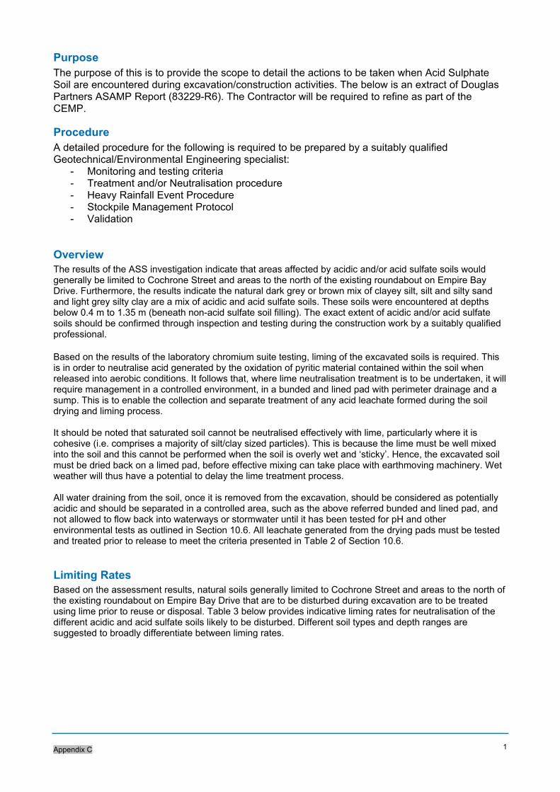
Appendix C
1
Purpose The purpose of this is to provide the scope to detail the actions to be taken when Acid Sulphate Soil are encountered during excavation/construction activities. The below is an extract of Douglas Partners ASAMP Report (83229-R6). The Contractor will be required to refine as part of the CEMP.
Procedure A detailed procedure for the following is required to be prepared by a suitably qualified Geotechnical/Environmental Engineering specialist:
- Monitoring and testing criteria - Treatment and/or Neutralisation procedure - Heavy Rainfall Event Procedure - Stockpile Management Protocol - Validation
Overview The results of the ASS investigation indicate that areas affected by acidic and/or acid sulfate soils would generally be limited to Cochrone Street and areas to the north of the existing roundabout on Empire Bay Drive. Furthermore, the results indicate the natural dark grey or brown mix of clayey silt, silt and silty sand and light grey silty clay are a mix of acidic and acid sulfate soils. These soils were encountered at depths below 0.4 m to 1.35 m (beneath non-acid sulfate soil filling). The exact extent of acidic and/or acid sulfate soils should be confirmed through inspection and testing during the construction work by a suitably qualified professional. Based on the results of the laboratory chromium suite testing, liming of the excavated soils is required. This is in order to neutralise acid generated by the oxidation of pyritic material contained within the soil when released into aerobic conditions. It follows that, where lime neutralisation treatment is to be undertaken, it will require management in a controlled environment, in a bunded and lined pad with perimeter drainage and a sump. This is to enable the collection and separate treatment of any acid leachate formed during the soil drying and liming process. It should be noted that saturated soil cannot be neutralised effectively with lime, particularly where it is cohesive (i.e. comprises a majority of silt/clay sized particles). This is because the lime must be well mixed into the soil and this cannot be performed when the soil is overly wet and ‘sticky’. Hence, the excavated soil must be dried back on a limed pad, before effective mixing can take place with earthmoving machinery. Wet weather will thus have a potential to delay the lime treatment process. All water draining from the soil, once it is removed from the excavation, should be considered as potentially acidic and should be separated in a controlled area, such as the above referred bunded and lined pad, and not allowed to flow back into waterways or stormwater until it has been tested for pH and other environmental tests as outlined in Section 10.6. All leachate generated from the drying pads must be tested and treated prior to release to meet the criteria presented in Table 2 of Section 10.6.
Limiting Rates Based on the assessment results, natural soils generally limited to Cochrone Street and areas to the north of the existing roundabout on Empire Bay Drive that are to be disturbed during excavation are to be treated using lime prior to reuse or disposal. Table 3 below provides indicative liming rates for neutralisation of the different acidic and acid sulfate soils likely to be disturbed. Different soil types and depth ranges are suggested to broadly differentiate between liming rates.
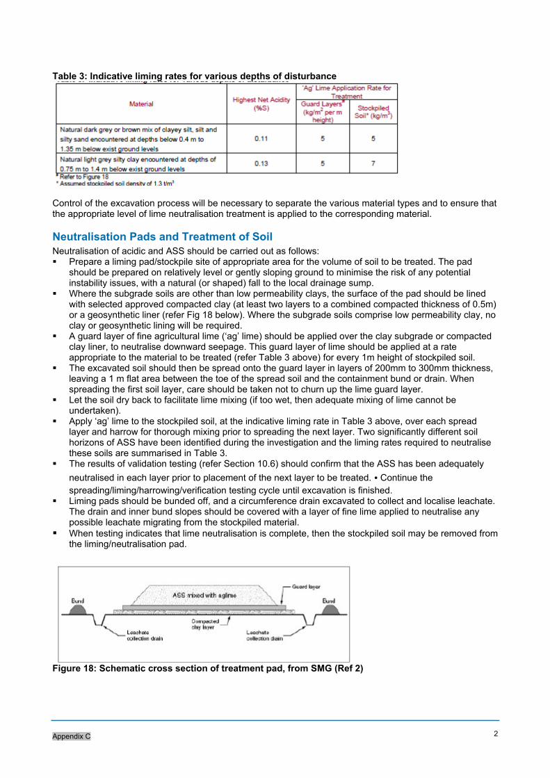
Appendix C
2
Table 3: Indicative liming rates for various depths of disturbance
Control of the excavation process will be necessary to separate the various material types and to ensure that the appropriate level of lime neutralisation treatment is applied to the corresponding material.
Neutralisation Pads and Treatment of Soil Neutralisation of acidic and ASS should be carried out as follows: Prepare a liming pad/stockpile site of appropriate area for the volume of soil to be treated. The pad
should be prepared on relatively level or gently sloping ground to minimise the risk of any potential instability issues, with a natural (or shaped) fall to the local drainage sump.
Where the subgrade soils are other than low permeability clays, the surface of the pad should be lined with selected approved compacted clay (at least two layers to a combined compacted thickness of 0.5m) or a geosynthetic liner (refer Fig 18 below). Where the subgrade soils comprise low permeability clay, no clay or geosynthetic lining will be required.
A guard layer of fine agricultural lime (‘ag’ lime) should be applied over the clay subgrade or compacted clay liner, to neutralise downward seepage. This guard layer of lime should be applied at a rate appropriate to the material to be treated (refer Table 3 above) for every 1m height of stockpiled soil.
The excavated soil should then be spread onto the guard layer in layers of 200mm to 300mm thickness, leaving a 1 m flat area between the toe of the spread soil and the containment bund or drain. When spreading the first soil layer, care should be taken not to churn up the lime guard layer.
Let the soil dry back to facilitate lime mixing (if too wet, then adequate mixing of lime cannot be undertaken).
Apply ‘ag’ lime to the stockpiled soil, at the indicative liming rate in Table 3 above, over each spread layer and harrow for thorough mixing prior to spreading the next layer. Two significantly different soil horizons of ASS have been identified during the investigation and the liming rates required to neutralise these soils are summarised in Table 3.
The results of validation testing (refer Section 10.6) should confirm that the ASS has been adequately
neutralised in each layer prior to placement of the next layer to be treated. • Continue the spreading/liming/harrowing/verification testing cycle until excavation is finished.
Liming pads should be bunded off, and a circumference drain excavated to collect and localise leachate. The drain and inner bund slopes should be covered with a layer of fine lime applied to neutralise any possible leachate migrating from the stockpiled material.
When testing indicates that lime neutralisation is complete, then the stockpiled soil may be removed from the liming/neutralisation pad.
Figure 18: Schematic cross section of treatment pad, from SMG (Ref 2)
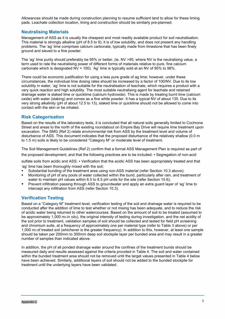
Appendix C
3
Allowances should be made during construction planning to resume sufficient land to allow for these liming pads. Leachate collection location, lining and construction should be similarly pre-planned.
Neutralising Materials Management of ASS as it is usually the cheapest and most readily available product for soil neutralisation. This material is strongly alkaline (pH of 8.5 to 9), it is of low solubility, and does not present any handling problems. The ‘ag’ lime comprises calcium carbonate, typically made from limestone that has been finely ground and sieved to a fine powder. The ‘ag’ lime purity should preferably be 95% or better, (ie. NV >95, where NV is the neutralising value, a term used to rate the neutralising power of different forms of materials relative to pure, fine calcium carbonate which is designated NV = 100). ‘Ag’ lime is typically sold at an NV of 95% to 98%. There could be economic justification for using a less pure grade of ag lime; however, under these circumstances, the individual lime dosing rates should be increased by a factor of 100/NV. Due to its low solubility in water, ‘ag’ lime is not suitable for the neutralisation of leachate, which requires a product with a very quick reaction and high solubility. The most suitable neutralising agent for leachate and retained drainage water is slaked lime or quicklime (calcium hydroxide). This is made by treating burnt lime (calcium oxide) with water (slaking) and comes as a fine white powder. It has a typical NV of about 135. Due to its very strong alkalinity (pH of about 12.5 to 13), slaked lime or quicklime should not be allowed to come into contact with the skin or be inhaled.
Risk Categorisation Based on the results of the laboratory tests, it is concluded that all natural soils generally limited to Cochrone Street and areas to the north of the existing roundabout on Empire Bay Drive will require lime treatment upon excavation. The SMG (Ref 2) relate environmental risk from ASS by the treatment level and volume of disturbance of ASS. This document indicates that the proposed disturbance of the relatively shallow (0.0 m to 1.5 m) soils is likely to be considered “Category M” or moderate level of treatment. The Soil Management Guidelines (Ref 2) confirm that a formal ASS Management Plan is required as part of
the proposed development, and that the following practices are to be included: • Segregation of non-acid
sulfate soils from acidic and ASS; • Verification that the acidic ASS has been appropriately treated and that ‘ag’ lime has been thoroughly mixed with the soil; Substantial bunding of the treatment area using non-ASS material (refer Section 10.3 above); Monitoring of pH of any pools of water collected within the bund, particularly after rain, and treatment of
water to maintain pH values within 6.5 to 8.5 pH units for the site (refer Section 10.6); Prevent infiltration passing through ASS to groundwater and apply an extra guard layer of ‘ag’ lime to
intercept any infiltration from ASS (refer Section 10.3).
Verification Testing Based on a “Category M” treatment level, verification testing of the soil and drainage water is required to be conducted after the addition of lime to test whether or not mixing has been adequate, and to reduce the risk of acidic water being returned to other watercourses. Based on the amount of soil to be treated (assumed to be approximately 1,000 m3 in situ), the original intensity of testing during investigation, and the net acidity of the soil prior to treatment, validation samples of soil should be collected and tested for field pH screening and chromium suite, at a frequency of approximately one per material type (refer to Table 3 above) or per 1,000 m3 of treated soil (whichever is the greater frequency). In addition to this, however, at least one sample should be taken per 200mm to 300mm deep soil stockpile layer per bunded area and may result in a greater number of samples than indicated above. In addition, the pH of all ponded drainage water around the confines of the treatment bunds should be measured daily and results assessed against the criteria provided in Table 4. The soil and water contained within the bunded treatment area should not be removed until the target values presented in Table 4 below have been achieved. Similarly, additional layers of soil should not be added to the bunded stockpile for treatment until the underlying layers have been validated.
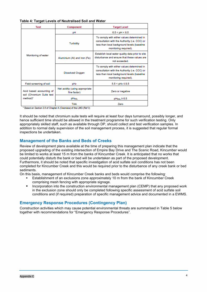
Appendix C
4
Table 4: Target Levels of Neutralised Soil and Water
It should be noted that chromium suite tests will require at least four days turnaround, possibly longer, and hence sufficient time should be allowed in the treatment programme for such verification testing. Only appropriately skilled staff, such as available through DP, should collect and test verification samples. In addition to normal daily supervision of the soil management process, it is suggested that regular formal inspections be undertaken.
Management of the Banks and Beds of Creeks Review of development plans available at the time of preparing this management plan indicate that the proposed upgrading of the existing intersection of Empire Bay Drive and The Scenic Road, Kincumber would be limited to works at least 15 m from the banks of Kincumber Creek. It is anticipated that no works that could potentially disturb the bank or bed will be undertaken as part of the proposed development. Furthermore, it should be noted that specific investigation of acid sulfate soil conditions has not been completed for Kincumber Creek and this would be required prior to the disturbance of any creek bank or bed sediments. On this basis, management of Kincumber Creek banks and beds would comprise the following:
Establishment of an exclusions zone approximately 10 m from the bank of Kincumber Creek comprising mesh fencing with appropriate signage.
Incorporation into the construction environmental management plan (CEMP) that any proposed work in the exclusion zone should only be completed following specific assessment of acid sulfate soil conditions and (if required) preparation of specific management advice and documented in a EWMS.
Emergency Response Procedures (Contingency Plan) Construction activities which may cause potential environmental threats are summarised in Table 5 below together with recommendations for “Emergency Response Procedures”.
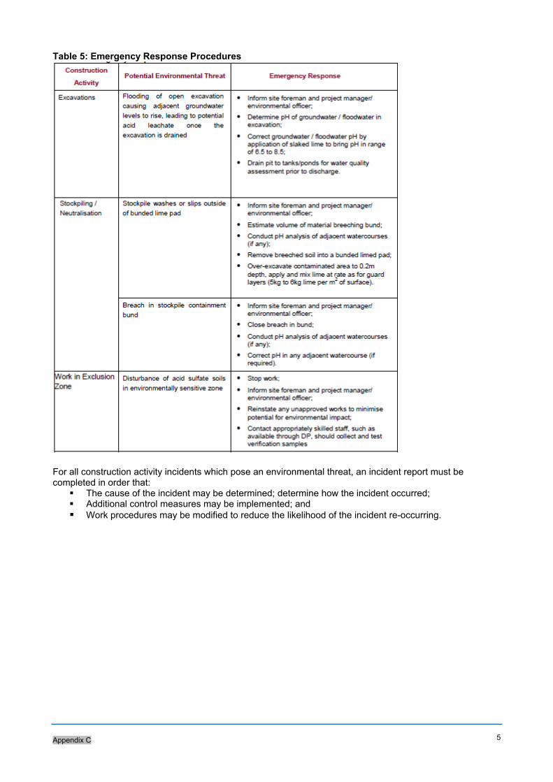
Appendix C
5
Table 5: Emergency Response Procedures
For all construction activity incidents which pose an environmental threat, an incident report must be completed in order that:
The cause of the incident may be determined; determine how the incident occurred; Additional control measures may be implemented; and Work procedures may be modified to reduce the likelihood of the incident re-occurring.

rms.nsw.gov.au
Customer feedback Roads and Maritime Locked Bag 928, North Sydney NSW 2059
Related Documents


