OEM Dynamics is a division of Animatics Corporation tel: 408.748.8721 • fax: 408.748.8725 • www.oemdynamics.com 70 SOFTWARE & FIRMARE Host Software source level debugger. Standard SMI features include a Tools menu to set PID tuning parameters and plot the step response, motor info and dynamic status tracking, and online help and doc- umentation. The latest release of SMI can open multiple windows for program editing, instantly address multiple motors, and upload programs from motors. Simply write and download your applica- tion to the configured SmartMotor and reboot the motor to start your application working. Download SMI at no cost from the Animatics website (www.animatics.com) or from the product CD-ROM, and use the installation wizard to install SMI, SMIEngine™, and Coordinated Motion. The SMIEngine is a component library that uses the Component Object Model (COM) to define functions that perform the follow- ing tasks: Configuring and communicating with Animatics SmartMotors • Compiling/Downloading/Uploading/Debugging compiled user • programs (“.smx” files) Controlling the motors using Coordinated Motion (Contour- • ing or Host Mode) Creating circular and linear path coordinates used for Coor- • dinated Motion Polling Features to Monitor Functions The Animatics SmartMotor Interface has special user-defined polling features to help you monitor important functions conve- niently. Monitor different status bits, variables, and I/O from any motor in a chain, even during application execution. SMI ▪ SmartMotor Interface SMI SMARTMOTOR INTERFACE Animatics’ SMI software provides an easy-to-use Microsoft Win- dows-compatible interface to your Animatics SmartMotor™. Using SMI, you can define multi-axis motion control for 1 to 100 Smart- Motors. SMI includes a terminal program, program editor, and Features in SMI The latest release of SMI leverages the strengths of the original SMI application with many advanced features. It adds extensive user interface improvements, functional enhancements, and new utilities that help you develop, test, run, and deploy your Animatics SmartMotor applications. SmartMotor Playground • . Would you like to be able to see and modify your motion control settings on-the-fly? With SMI , you can. Connect your SmartMotor to your computer, start SMI , and the SmartMotor Plaground window opens. SMI automatically detects connected motors and gathers data in the Motor Info tab. In the SMI Playground, you can modify Torque, Velocity, and Position settings in real-time. Using numerical values for input, or the interactive interface with drag and drop, sliders, and radio buttons, you can see the results immediately.

Welcome message from author
This document is posted to help you gain knowledge. Please leave a comment to let me know what you think about it! Share it to your friends and learn new things together.
Transcript

OEM Dynamics is a division of Animatics Corporation tel: 408.748.8721 • fax: 408.748.8725 • www.oemdynamics.com70
SOFT
WA
RE
& F
IRM
AR
E
Host Software
source level debugger. Standard SMI features include a Tools menu to set PID tuning parameters and plot the step response, motor info and dynamic status tracking, and online help and doc-umentation. The latest release of SMI can open multiple windows for program editing, instantly address multiple motors, and upload programs from motors. Simply write and download your applica-tion to the configured SmartMotor and reboot the motor to start your application working.
Download SMI at no cost from the Animatics website (www.animatics.com) or from the product CD-ROM, and use the installation wizard to install SMI, SMIEngine™, and Coordinated Motion.
The SMIEngine is a component library that uses the Component Object Model (COM) to define functions that perform the follow-ing tasks:
Configuring and communicating with Animatics SmartMotors• Compiling/Downloading/Uploading/Debugging compiled user • programs (“.smx” files)Controlling the motors using Coordinated Motion (Contour-• ing or Host Mode)Creating circular and linear path coordinates used for Coor-• dinated Motion
Polling Features to Monitor FunctionsThe Animatics SmartMotor Interface has special user-defined polling features to help you monitor important functions conve-niently. Monitor different status bits, variables, and I/O from any motor in a chain, even during application execution.
SMI ▪ SmartMotor Interface
SMISMARTMOTORI N T E R F A C E
Animatics’ SMI software provides an easy-to-use Microsoft Win-dows-compatible interface to your Animatics SmartMotor™. Using SMI, you can define multi-axis motion control for 1 to 100 Smart-Motors. SMI includes a terminal program, program editor, and
Features in SMI The latest release of SMI leverages the strengths of the original SMI application with many advanced features. It adds extensive user interface improvements, functional enhancements, and new utilities that help you develop, test, run, and deploy your Animatics SmartMotor applications.
SmartMotor Playground• . Would you like to be able to see and modify your motion control settings on-the-fly? With SMI , you can. Connect your SmartMotor to your computer, start SMI , and the SmartMotor Plaground window opens. SMI automatically detects connected motors and gathers data in the Motor Info tab. In the SMI Playground, you can modify Torque, Velocity, and Position settings in real-time. Using numerical values for input, or the interactive interface with drag and drop, sliders, and radio buttons, you can see the results immediately.

OEM Dynamics is a division of Animatics Corporation tel: 408.748.8721 • fax: 408.748.8725 • www.oemdynamics.com 71
SOFTW
AR
E &
FIRM
WA
RE
Projects Feature• . Do you need to put an SMI project on hold? You can save your communications, configuration, and preferences settings with the new Project option. The Project menu option allows you to manage and save your work-space settings and applications configuration settings.
SMI ▪ SmartMotor InterfaceHost Software
New dockable windows• . The Animatics’ newest release of SMI workspace now includes dockable windows that you can access from the toolbar. Simply double-click the title bar to toggle the window between floating and docked views.The Information view displays error and information mes-sages and allows you to go directly to the message’s source location.
The Serial Data Analyzer view displays data transfers between your computer and Animatics SmartMotor™. You can filter the data to display only the information you want; for example, choose to display transmitted data, received data, or echoed data.
The Configurationview displays the current communication and motor configuration in a hierarchy structure that you can save as a Project for reuse.
The Terminal view creates a tabbed page for each port so you can communicate with individual or multiple SmartMotors.
Additional views have been added to help you collect data • and monitor SmartMotor operation. The Chart View is a col-lection of user-defined motor parameters (Chart Items) that you can select to monitor during motor operation in a dynamic graphical display.
These are just a few of the new features available in the latest release of SMI . Other enhancements include:
Syntax Highlighting - Uses different colors for different code • elements, such as keywords or commentsStatus bar information - Displays the current cursor position • and the SmartMotor language version of the active file in the status barContext Menu - Right mouseclick displays a menu of • frequently-used commands
With SMI, you get a robust software application specifically designed to manage your SmartMotor motion control require-ments.

OEM Dynamics is a division of Animatics Corporation tel: 408.748.8721 • fax: 408.748.8725 • www.oemdynamics.com72
SOFT
WA
RE
& F
IRM
AR
E
Host SoftwareSmart Select Interface
Smart SelectI N T E R F A C E TM
Animatics Smart Select Interface is a Point-And-Click Approach to programming Animatics SmartMotors. This interface is a configuration tool allowing the user to program the motor for pre-set motion profiles such as:
Absolute Position Moves• Relative Position Moves• Constant Velocity Move• Reduce Torque Limited Velocity Moves• Open Loop Torque Mode• Dynamic Braking•
In this simple approach, the user can predefine all moves and then simply connect the I/O to a PLC and allow the PLC to trigger motion as needed.
I/O is assigned as follows:
Ports A, B, C, and D: 4-bit binary 1-of-16 selection Port G: “GO” input Port E: “Busy Moving” Output Port F: “Fault” Output
The user can set scale factors and choose units in
inches• millimeters• microns• degrees• revolutions•
There are several built-in Home routine methods as well as manual homing. A graphical representation aids the user in Home Method Selection
On-line diagnostics section includes:
Manual Jogging• Direct Terminal Window• I/O Status• Direct Drive and Control Command Buttons•
Tuning Made Simple: with the “Easy Tune Slider”
Simple slide-action Servo tuning to take the hassle out of guess-work.
All data is saved to both the motor and hard drive. Multiple “axis Data Files” can be saved, edited and recalled for later transfer to other motors.
For ease of testing and troubleshooting, the SmartBoxBCD Switchbox™ is also available. It is designed to emulate I/O hand shaking from a PLC.
See page:120 for more details.

OEM Dynamics is a division of Animatics Corporation tel: 408.748.8721 • fax: 408.748.8725 • www.oemdynamics.com 73
SOFTW
AR
E &
FIRM
WA
RE
SmartMotor Numeric Control SoftwareSMNC™
applications. SMNC provides a set of features that are compa-rable to any CNC system, including a user interface that is similar in appearance to a traditional CNC system. Review the table in this section to see the G and M Codes that are supported by SMNC software.
SMNC standard features include:Linear and circular motion control of multiple axes• Configures SmartMotors across multiple serial ports• Converts CAD-DXF files into motion control G and M Codes• Duplication of axis motion for gantry systems• Smooth control of acceleration and deceleration for sensitive • curvilinear motionLarge numerical display• 6 axis control, includes axes mimic and spindle• RS232 and RS485 communication• User-definable M-Codes for digital output• Displays source code during execution• Writes and edits any G-Code program in the source view, • with added support for:
3D linear movements•
CW and CCW Circular movements•
CW and CCW Helical Movements•
Wait, Pause, definable M-Codes, Spindle Commands • and more
Defines up to 30 M-Code commands and views their status • during executionImports graphic files with DXF format and converts them to • G-Code programsExports G-Code programs to Coordinated Motion Files• Checks and runs a G-Code program or Coordinated Motion • fileChecks features during G-Code program execution: •
Fee• d Hold Single step • Reset (End)•
Emergency stop•
Jogs the device using the Jog Buttons, and moves it to any • location using the Go to utility on the Panel viewControls the Spindle using related buttons on the Panel • View. The Spindle can be a SmartMotor or any other type of motor controlled by M-Codes and digital outputsSets any connected SmartMotor in Coordinated Motion • Mode, Spindle Mode, Mimic Mode, Rotary/Vector Mode, or Uncoordinated Mode
New features:Define up to 30 Inputs to perform SMNC functions, such as • Start, Reset, and Feed Hold, or as interlocksDefine up to 10 different tools. The current tool can be • changed in a G-Code program.Password protection to control user access for many fea-• turesDefine up to 6 different coordinate systems (G56-G59)• Customizable homing methods•
G and M codes supported by SMNC
Codes DescriptionG0 Rapid Linear movementG1 Normal Linear movementG2 Clockwise circular movementG3 Counter-Clockwise circular movementG4 WaitG17 Select the X-Y plane for circular movementsG18 Select the X-Z plane for circular movementsG19 Select the Y-Z plane for circular movementsG20 Change units to inchG21 Change units to MillimeterG28 Return to the 1st Reference pointG30 Return to the 2nd Reference pointG40 Cancel cutter compensationG41 Start cutter compensation leftG42 Start cutter compensation rightG43 Start tool length compensationG49 Cancel tool length compensationG54 Use preset coordinate system 1G55 Use preset coordinate system 2G56 Use preset coordinate system 3G57 Use preset coordinate system 4G58 Use preset coordinate system 5G59 Use preset coordinate system 6G80 Cancel Modal Motion (Used with canned cycles)G81 Canned cycle: drillingG82 Canned cycle: drilling with dwellG83 Canned cycle: peck drillingG85 Canned cycle: boring, no dwell, feed outG89 Canned cycle: boring dwell feed outG90 Change coordinate system to absoluteG91 Change coordinate system to incrementalG92 Change the logical originG98 Initial level return mode in Canned cycleG99 Retract-point level return mode in Canned cycleG101 Move the rotary axisD Change the tool index for cutter compensation (G40, G41, G42)F Change the Feedrate (Normal Speed)H Change the tool index for tool length compensation (G43, G49)S Change the Spindle SpeedT Current tool index (M6)M0 PauseM1 Optional StopM2 End of program
M3 Turn on Spindle ClockwiseM4 Turn on Spindle CounterclockwiseM5 Turn off SpindleM6 Change current ToolM8 Turn on the CoolantM9 Turn off the CoolantM30 End of program and force turning off all of digital outputsM99 End the program and restart it
SMNC™, Animatics’ G-Code based servo motion control soft-ware, uses numeric control to deliver multi-axis contouring for your Animatics SmartMotor™

OEM Dynamics is a division of Animatics Corporation tel: 408.748.8721 • fax: 408.748.8725 • www.oemdynamics.com74
SOFT
WA
RE
& F
IRM
AR
E
JenCNC™
JenCNC featuresUpon start-up, JenCNC automatically detects motors and • does a system update if any Animatics SmartMotor™ was changed out. This allows you to place the shortcut in the start-up directory to allow automatic restart on loss of powerA full machine settings window allows for customization to • physical dimensions of the machining spaceMachine tolerance levels can be set to ensure that no • product damage occurs in the event of motor drop-out or path divergenceSlow-down proportional-to-angle can be tailored to mini-• mize machining time while providing the best surface finish through sharp turnsCustomizable G-Codes for user-defined tooling positions• Customizable M-Codes for I/O control and SmartMotor • commands or subroutine callsAbility to call G-Code subroutines• Ability to repeat a section of G-code any number of times• Z-Axis (tool length) offsets• SAE or metric scaling• On-screen and keyboard real-time jogging• Auto-detection of Windows-compatible joystick for jog • controlMenu-selectable Inputs set-up window• Wait-on-input definable M-Codes• Customizable outputs assignable to user-definable M-Codes• CMM probing for setting tool offset• Terminal screen diagnostics page for testing and trouble-• shootingUser-selectable homing routines with configurable offsets• Advanced settings screen includes events set-up for E-Stop • conditions
Multi-Axis Contouring Software
Animatics’ JenCNC is a full-featured 3D CNC software package designed exclu-sively to run Animatics SmartMotors.
JenCNC combines features of both a CAD/CAM and a motion-control software package into a unique graphical user interface for controlling two to four SmartMotors™ in true 3D coordinated motion. With real time 2D and 3D plotting to the screen, DXF-to-G-Code conversion, and conversational G-Code building, your CNC machine will be up and running in no time. JenCNC utilizes a simple serial interface to communicate and control SmartMo-tors. Using custom algorithms, motion is optimized for smooth control and continuous operation for all your machining needs. Due to its ability to run in a constant vector velocity, regardless of changes in direction, the software is ideal where dispensing or flow rate of glue or adhesives is critical to the process.
JenCNC is built on many years of in-field testing and customer feedback in real-world applications, including:
Routers (gantry machining of aluminum, foam, vinyl, and • wood)Hot-wire EPS foam cutting• Plasma (oxy-fuel) cutting with torch height control• Machining forms for vacuum-form molding of plastics• Milling machine retrofits• Sign making• Engraving• CNC drilling• Gasket cutting• Adhesive applicators•
We strive to continuously improve its capabilities according to the needs and demands of our customers in order to provide the best possible solution for any need that may arise. Custom features can be added at a competitive rate. Please contact Animatics at 408.748.8721 for more information.
DXF to G-code converter:JenCNC’s built-in DXF-to-G-Code converter allows you to open and view DXF files. Once in view, you can select entities in the order you wish to have the motors move. The converter includes a set-up for the Z-Axis. If you left click from one entity to the next, the Z-Axis motion G-Code is automatically generated.
All entities connected end-point to end-point will produce a con-tinuous path until the need of the selection is reached. If the inter-preter comes to a “Y” in the path, it will choose the path of least resistance (angular displacement).
There is an additional “Join” tolerance set-up. You can set the distance tolerance from one entity to the next in case the entities are not actually connected at their end-points.
If within that tolerance, the interpreter assumes connection and continues the path through the entities as one continuous motion. This can be very useful if the original DXF file was created free-hand, as part of an artist rendering where O-Snaps may not have been used.
OEM Dynamics is a division of Animatics Corporation tel: 408.748.8721 • fax: 408.748.8725 • www.oemdynamics.com 75
SOFTW
AR
E &
FIRM
WA
RE
JenCNC™
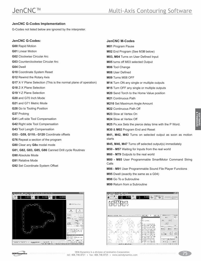
JenCNC G-Codes:G00 Rapid Motion
G01 Linear Motion
G02 Clockwise Circular Arc
G03 Counterclockwise Circular Arc
G04 Dwell
G10 Coordinate System Reset
G12 Rewind the Rotary Axis
G17 X-Y Plane Selection (This is the normal plane of operation)
G18 Z-X Plane Selection
G19 Y-Z Plane Selection
G20 and G70 Inch Mode
G21 and G71 Metric Mode
G28 Go to Tooling Position
G37 Probing
G41 Left side Tool Compensation
G42 Right side Tool Compensation
G43 Tool Length Compensation
G53 - G59, G110.- G120 Coordinate offsets
G76 Repeat a section of the program
G80 Clear any G8x modal mode
G81, G82, G83, G85, G86 Canned Drill cycle Routines
G90 Absolute Mode
G91 Relative Mode
G92 Set Coordinate System Offset
JenCNC M-CodesM01 Program Pause
M02 End Program (See M30 below)
M03, M04 Turns on User Defined Input
M05 turns off M03 selected Output
M06 Tool Change
M08 User Defined
M09 Turns M08 OFF
M14 Turn ON any single or multiple outputs
M15 Turn OFF any single or multiple outputs
M20 Send Torch to the Home Value position
M21 Continuous Path
M210 Set Maximum Angle Amount
M22 Continuous Path Off
M23 Slow at Vertex On
M24 Slow at Vertex Off
M25 Px.xxx Sets the pierce delay time with the P Word.
M30 & M02 Program End and Reset
M41, M42, M43 Turns on selected output as soon as motion starts
M45, M46, M47 Turns off selected output(s) immediately
M50 - M57 Waiting for Inputs from the real world
M60 - M79 Outputs to the real world
M80 - M85 User Programmable SmartMotor Command String Calls
M86 - M91 User Programmable Sound File Player Functions
M95 Dwell (exactly the same as a G04)
M98 Go To a Subroutine
M99 Return from a Subroutine
JenCNC G-Codes ImplementationG-Codes not listed below are ignored by the interpreter.
Multi-Axis Contouring Software

OEM Dynamics is a division of Animatics Corporation tel: 408.748.8721 • fax: 408.748.8725 • www.oemdynamics.com76
SOFT
WA
RE
& F
IRM
AR
E
SMIEngine™Programmer’s Resource Tools
Animatics’ SMIEngine™ is a source code module library created as a software tool for the Windows Operating System environ-ment. It comes free with the installation of the SMI software.
The installation includes source code examples written in:
Borland C++, Microsoft C++, Visual C, VB and VBA (Excel).
SMIEngine is based on the Windows Component Object Model (COM) and works with:
Microsoft C++• Borland C++• Microsoft Visual Basic (VB)• VBA (Visual Basic for Applications)• MS.Net environment• Borland Delphi• Pascal• Python• LabView (when installed as an Active-X component)•
Note about Windows Vista: With the release of Microsoft Vista, the name of the dll file changes from SMEengine.dll to IntegMo-torInterface.dll. Other than the name change, all internal defini-tions have remained the same and are fully backwards compat-ible to existing applications with no need to change the body of the source code.
Using SMIEngine, you can perform the following tasks:
Configure PC serial ports• Address Animatics SmartMotors™ through selected serial • portsSend commands to the motors and receive motor responses • that allow you to:
Control and change modes of operation•
Update or change motion parameters and variables•
Gather real-time data from motors for online diagnostics•
Control the motors using Coordinated Motion (Contour-• ing or Host Mode)
Create circular and linear path coordinates used for • Coordinated Motion
Work with downloadable SmartMotor code to:• Scan user program source files (.sms) for errors•
Create an executable SmartMotor compiled user program • file (.smx)
Download and upload compiled user programs to and • from motors
Create a list of errors in a user program and provide an •
interface for navigating through errors
Optimizing the SMIEngine for Multi-Axis coordinated Motion Control:Multiple Instances of the SMIEngine can be run at the same time for each communications port that is open. In doing so, the application can maximize usage of communications bandwidth to each motor or each set of motors. Highly effective and efficient applications can be created to control CNC machines via a PC.
Example Application using SMI Engine:The Animatics JenCNC software package was created in Borland C++ using the SMIEngine exclusively to handle all Motor com-munications. The result was a stable and proven CNC platform for controlling up to 4 axis machines via a standard RS-232 serial port.

OEM Dynamics is a division of Animatics Corporation tel: 408.748.8721 • fax: 408.748.8725 • www.oemdynamics.com 77
SOFTW
AR
E &
FIRM
WA
RE
Firmware and Hardware Options
Standard Firmware < 4.60Standard Firmware for Animatics OEM and Legend Series SmartMotors™
RS232 & RS485 ASCII Communication RS485 Line Data Control Printing to a COM Channel Reporting COM Channel ProtocolAbility to manually parse incoming data
Input/Output Software Selectable I/O Commands Analog Input, Digital Input, and Digital Output Encoder I/O Travel Limit Inputs
Motion Modes Velocity ModeTorque ModePosition Mode (Absolue/Relative)Variable Electronic Gearing with Phase OffsetVariable Step and Direction Ratio with Phase Offset CAM Mode with Variable DwellContouring Mode
Additions From Past Firmware Release Directional Limit and Limit Trigger High/Low Addition of Coordinated Motion
Programming Language Variables-Variable and Arrays Names Initializing Variables and Arrays Control Flow
Creating Motion Position Mode, Velocity Mode and Torque Mode Integrated Brake Commands External Encoder & Primary Encoder Commands Gravity Constant Directional Limit Inputs Motor and Load Protection
Firmware “PLUS” Optional Firmware for Animatics OEM and Legend Series SmartMotors™ *Consult factory for other firmware options PLUS greatly increases performance in applications such as: traverse-and-take-up, material transport, automatic reversal on soft limit, specialized coil winding and lapping of materials, and high-speed material inspection scanning.
Advanced Drive Capabilities NOTE: Must specify 4.78T firmware PWM controlled Dynamic braking >30% better slowing power to prevent overshoots in speed or deceleration during the entire trajectory path. Provides protection against exceeding critical speed limits of lead screws
Interrupt Fault Handler Motor protection must be reset via ZS or a specific command Protection fault
Ends the running program or • Call a specific subroutine on interrupt•
Overtravel Limit Control Positive and Negative Software Limits Hardware and Software Limits are directional and active-high asserted.
Mode of Operation Mode-Torque-Brake (MTB) allows smooth deceleration of loads MTB default mode MTB draws no additional current from the power supply
AM Mode Extensions Relative CAM Mode Configurable Dwell CAM Index out for position triggering
Output Option Automatic external brake-control
Input Option Separate interrupt handler on edge triggering Reverse Shaft Rotation Option
* Note: To order, add “-PLS” to the standard SM part number
Hardware
E-Stop Switch
Drive Amp Power Supply:(20-48VDC)
DRV PWR GNDDRV POWER
Control Power Supply:(20-48VDC)
CONTROL POWERCONTROL PWR GND
Note:One supply can be used for both Control Powerand Drive amp Power, but maximum protection isprovided with separate power supplies.
Protective Shuntsee pages 123 and 126
The DE option allows the Animatics OEM and Legend Series controller and drive-amplifier to be powered from separate 24-48 VDC power supplies.
Controller can be powered from a standard 24 VDC supply• Position will not be lost on loss-of-drive-power• No need to re-home• Load surges will not cause power surge on controller• Standard battery options are made simpler•
* Note: To order, add “-DE” to the standard SM part number