Software Requirements Specification (SRS) Project CACC++ 4 Authors: Justin Newman, Rohit Sen, Matt Howard, Sam Belcher, Noah Engerer Customer: James Daly Instructor: James Daly

Welcome message from author
This document is posted to help you gain knowledge. Please leave a comment to let me know what you think about it! Share it to your friends and learn new things together.
Transcript
Software Requirements Specification (SRS)
Project CACC++ 4
Authors: Justin Newman, Rohit Sen, Matt Howard, Sam Belcher, Noah Engerer
Customer: James Daly
Instructor: James Daly
1
Table of Contents
Table of Contents……………………………………………………………… 1 List of Figures………………………………………………………………….. 2 1.0 Introduction………………………………………………………………… 3
1.1 Purpose…………………………………………………………………………… 3 1.2 Scope……………………………………………………………………………… 3 1.3 Definitions, Acronyms, and Abbreviations…………………………………….. 5 1.4 Organization………………………………………………………………………. 6
2.0 Overall Description………………………………………………………… 7 2.1 Product Perspective……………………………………………………………… 7 2.2 Product Functions………………………………………………………………… 8 2.3 User Characteristics…………………………………………………………….. 10 2.4 Constraints……………………………………………………………………….. 10 2.5 Assumptions and Dependencies………………………………………………. 11 2.6 Approportioning of Requirement……………………………………………….. 11
3.0 Specific Requirements……………………………………………………. 12 4.0 Modeling Requirements………………………………………………….. 13 5.0 Prototype…………………………………………………………………… 21
5.1 How to Run Prototype…………………………………………………………… 21 5.2 Sample Scenarios……………………………………………………………….. 22
6.0 References………………………………………………………………… 22 7.0 Point of Contact…………………………………………………………… 23

2
List of Figures
Figure 1………………………………………………………………………… 8 Figure 2………………………………………………………………………… 14 Figure 3……………………………………………………………………….... 15 Data Dictionary 1…………………………………………………………….... 15 Data Dictionary 2…………………………………………………………….... 16 Data Dictionary 3…………………………………………………………….... 17 Data Dictionary 4…………………………………………………………….... 17 Data Dictionary 5…………………………………………………………….... 18 Data Dictionary 6…………………………………………………………….... 18 Data Dictionary 7…………………………………………………………….... 19 Figure 4……………………………………………………………………….... 20 Figure 5……………………………………………………………………….... 20 Figure 6……………………………………………………………………….... 21 Figure 7……………………………………………………………………….... 21
3
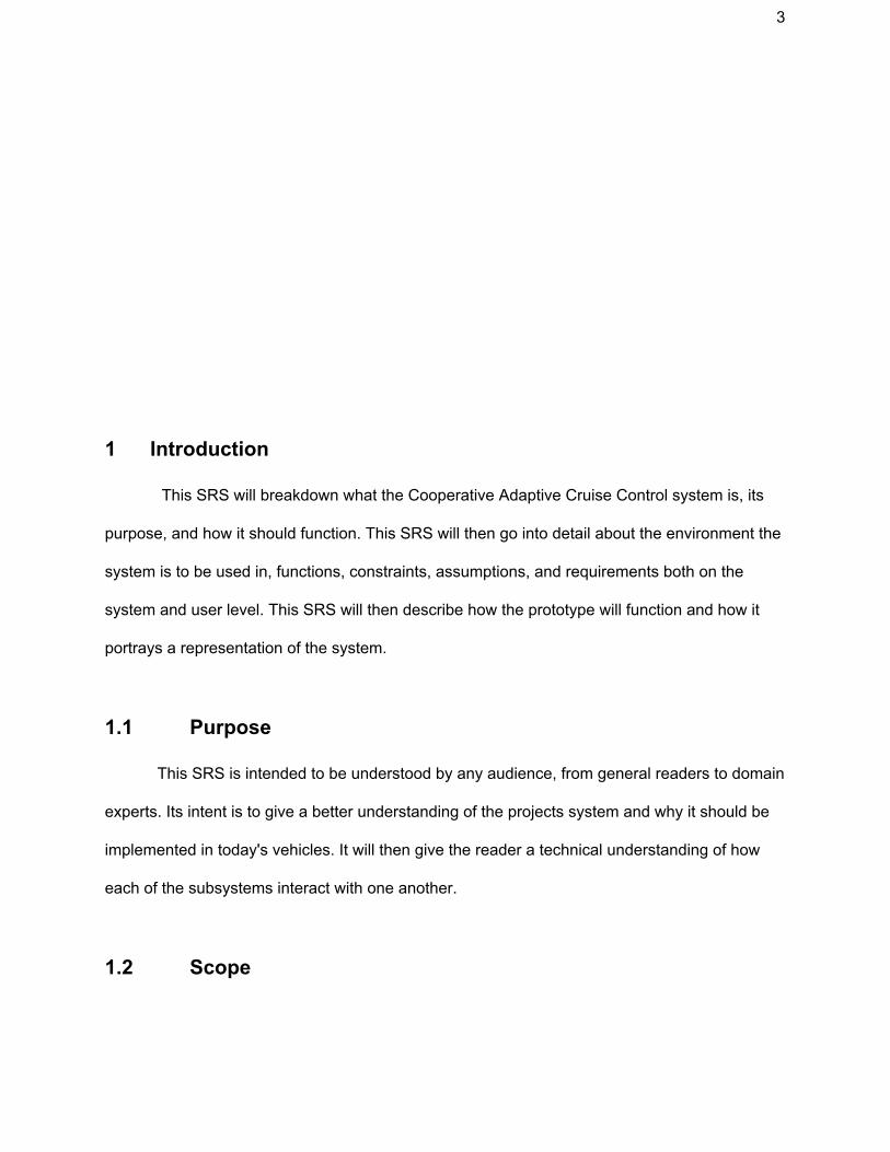
1 Introduction
This SRS will breakdown what the Cooperative Adaptive Cruise Control system is, its
purpose, and how it should function. This SRS will then go into detail about the environment the
system is to be used in, functions, constraints, assumptions, and requirements both on the
system and user level. This SRS will then describe how the prototype will function and how it
portrays a representation of the system.
1.1 Purpose
This SRS is intended to be understood by any audience, from general readers to domain
experts. Its intent is to give a better understanding of the projects system and why it should be
implemented in today's vehicles. It will then give the reader a technical understanding of how
each of the subsystems interact with one another.
1.2 Scope
4
The Cooperative Adaptive Cruise Control++ (CACC++) system aims to provide a safer
and more hands free experience for the driver. The system maintains a safe following distance
by reacting to different weather and road conditions. The system communicates with other
vehicles to create a platoon and is best fit for expressways where speed is kept constant over a
longer period of time. The system has control over the actuators which handle acceleration and
deceleration to maintain an appropriate speed. The goal of the system is to reduce the number
of accidents in cruise control situations. Overall, the system aims to provide a more enjoyable
and relaxed ride to its passengers by controlling the vehicle's acceleration. The platoon system
is beneficial to those who are traveling in groups as it will keep the cars together in a much safer
manner. Furthermore, the system benefits the overall flow of traffic as the safe following
distance is updated with the current speed of the vehicles, allowing the vehicles to travel faster,
thus increasing efficiency.
The CACC++ system is implemented in a vehicle and interacts with the brakes and
throttle of the vehicle in order to adjust the speed of the vehicle when it is deemed necessary.
The system interacts with any other vehicle within the platoon to share the vehicle’s
performance envelope and GPS information. In addition, the system interacts with the following
features of the vehicle: cruise control, lane keeping/centering, curve speed assist, and hill
management. The system must obey any traffic laws that are active where the vehicle is being
operated. The system has one user, the driver of the vehicle, and the driver will be a person
who has the appropriate license(s) to drive the vehicle.
The primary function of the Cooperative Adaptive Cruise Control++ system is to ensure
that vehicles on the road maintain a safe following distance behind other vehicles, safeguarding
against potential collisions without disrupting traffic flow. Existing cruise control systems allow
drivers to set, and maintain a speed, but are not capable of reacting to a number of

5
circumstances, including traffic, road and vehicle conditions, and driver error, often leading to
dangerous scenarios. With equipment to collect data about a vehicle, its environment, and
surrounding vehicles, as well as infrastructure to share this data amongst groups of vehicles, it
should be possible to create an automated system to control the speed of vehicles and keep
proper distancing. A shared control platform, coordinating multiple vehicles in platoons, would
allow groups of vehicles to travel safely at a significantly reduced risk of accident.
1.3 Definitions, acronyms, and abbreviations
● Safe following distance: vehicles will follow at a four second headway during clear
weather conditions. This distance will be calculated using the Radar Sensing subsystem,
with the GPS and Forward Looking Camera subsystems having the same capability in
the event the Radar Sensing subsystem fails. Adjusts in the event of bad weather:
○ Light Rain/Hail: +1 second
○ Heavy Rain/Hail: +2 seconds
○ Snow: +3 seconds
○ Ice on road: +4 seconds
● Target vehicle: The vehicle directly in front of another
● Trailing Vehicle: The vehicle directly behind another
● Subsystems:
○ Radar Sensor: ability to detect, id, and track the position of target vehicles.
○ Radio Communication: ability to communicate with target vehicle, trailing vehicle,
and infrastructure.
○ Electronic Throttle Control: ability to regulate vehicle speed by electronically
adding and removing power.

6
○ Brake by Wire: ability to decrease vehicle speed by applying brakes.
○ GPS System: ability to use GPS to keep accurate records of vehicle position,
speed, and direction. Ability to aid Radar Sensor in differentiating between target
vehicles and obstacles in the road.
○ Forward Looking Camera: ability to visually identify target vehicles and estimate
their distance away and relative speed. Ability to provide backup for the Radar
Sensor regarding tracking target vehicles
○ Vehicle Controller: The centralized subsystem of this project which coordinates
all other subsystems. Receives information from all other substems and executes
the braking or accelerating of the vehicle.
● Performance Envelope: Data indicating the vehicle’s braking and acceleration
capabilities that can be sent to other vehicles in the platoon.
● Platoon: Group of vehicles communicating with each other to maintain speed with a safe
distance between the cars.
● CACC++: Cooperative Adaptive Cruise Control++
● LMS: Lane Management Systems, keep the vehicle within its lane.
● Hill Management System: an external system that adjusts the speed of the vehicle when
going up or down hills.
● Headway: Measurement of time between the a vehicle and the their target vehicle.
1.4 Organization
The rest of this SRS will go into the technical understanding of the system and will be
organized as follows:
● Overall description
7
● Specific Requirements
● Modelling Requirements
● Prototype
● References
2 Overall Description
This section will cover information regarding system interfaces which includes user,
hardware, and software interfaces. Major product functions will be discussed and how they
interact with one another and the user. Assumptions, both about the user and the system, and
constraints on the system will be explained. Lastly, certain requirements that are beyond the
current scope of the project will be addressed.
2.1 Product Perspective
The context of this product is that it is a subsystem to be integrated into a vehicles
system. The system of this product is then broken down into its own subsystems. This product’s
system is not always active, but will be able to be activated and deactivated while the vehicle is
in motion. It is intended for use when a constant speed will be keep like with highway or country
road driving. This products system is not intended to be used for city driving.
The following is a high level use case model for how each subsystem should interact
with each other:

8
Figure 1
2.2 Product Functions
The product’s software will be able to perform these major functions:
● Detect and track: The software will be able to detect, id and track the motion and
position of target vehicles. This will be done using the Radar Sensor with the GPS
System and Forward Looking Camera available as backups in the event of Radar
Sensor failure.
● Distance Calculation: The software will be able to calculate how far away a target
vehicle is and also be able to calculate their speed. This will be done using the Forward
Looking Camera.
9
● Regulation of Speed: The system has the ability to regulate the speed of the vehicle by
either applying the brakes or throttle.
● Distance Maintaining: The software will be able to Maintain a safe following distance
during various weather conditions and terrains. This is done by first calculating the
distance and speed of the target variable. Once this is obtained, the headway can be
calculated. Once calculated, the system utilizes the regulation of speed functionality to
obtain a 4 second headway. This will be modified given the weather conditions.
● Lane Keeping: Using the forward looking camera, the system has the ability to identify
the lane that the vehicle is driving in and can adjust the steering of the car to stay within
the current lane. This functionality will also work in bad weather conditions, going up hill,
and around turns.
● Platoon Formation: The system has the ability to form a platoon with other vehicles
utilizing this products system. Vehicles will be following a lead vehicle, with each vehicle
having its own target vehicle (besides the lead vehicle). In the event that the platoon is
separated, two sub platoons are created.The vehicle in front of the trailing sub platoon
now becomes the lead vehicle for that sub platoon. The sub platoons can be joined into
a singular platoon upon catching up to one another. Platoons can be split into as many
sub platoons as needed in the event that they are continuously separated.
● Communications: The system has the ability to communicate and share information
with other vehicles in the platoon. This will be done using the Radio Communication
System and the GPS System. Information shared includes vehicle positions, speeds,
directions, as well as the vehicle’s performance envelopes.

10
2.3 User Characteristics
The following lists out expectations/assumptions about the user of this product:
● The user is legally allowed to drive and has a valid driver's license.
● The user does not need to be an expert driver, but should be comfortable driving on
highways and comfortable with the fact that this product will help control the vehicle.
● The user should know how to activate and deactivate the product.
● The user should be aware of the product functions listed above, as they will be
happening real time while the vehicle is in motion.
● The user must remain engaged and have their eyes on the road while the car is in
motion.
2.4 Constraints
● Implementation of communication services such that all vehicles always have the most
updated information.
● Proper decision making by the Vehicle Controller subsystem in the event that two or
more subsystems have conflicting values to send to brake/throttle. This constraint is
safety critical
● Implementing target vehicle tracking such that it maintains accurate vehicle detection
while going around turns. This constraint is safety critical.
● Proper memory management when dynamically creating and destroying software
objects. This is to reduce the probability of the event that a subsystem has not enough
memory to execute a task. This constraint could result in the system not performing
properly if violated
11
2.5 Assumptions and Dependencies
Hardware
● The hardware subsystems (forward looking camera, GPS system, radar sensor) are
assumed to still function under weather conditions listed under “safe following distance”.
Software
● Braking and throttle should be electronic and able to be actuated by software.
Environment
● This system is assumed to be used on Interstate highways or back country roads (long
stretches of road where a constant speed speed is manageable).
User Interactions
● The only interaction between the user and system is the initial setting of cruise control
speed, and the turning off of cruise control.
2.6 Approportioning of Requirements
Requirements that are beyond the scope of this project and will be implemented in future
versions are Lane Keeping and Curve Speed assistance. Both of these are due to the fact that
accurately detecting the target vehicle around curves will present a challenge and should be fine
tuned before release.

12
3 Specific Requirements
The following list of requirements are necessary for the vehicle to function appropriately
according to the given specifications. The following requirements are distinguished into user
requirements and system requirements. The requirements below are also ordered by a
hierarchical numbering scheme, i.e. according to the importance of the requirement.
System Requirements:
1) Must be equipped with the capability to send/receive information to/from other
vehicles regarding location, speed, and direction via GPS. Performance
envelopes for each vehicle can also be shared via wireless data transfer.
2) The system must be able to set up a platoon with other vehicles and maintain
safe following distances between each vehicle using the information shared
between them.
3) While in platoon formation, the system will be able to account for braking and
accelerating capabilities of cars when maintaining a safe following distance.
4) Being able to determine which subsystem should have priority when two or more
subsystems have conflicting actions (i.e. one trying to accelerate while one trying
to brake). This is done via the Vehicle Controller.
5) Implementing proper memory management (no memory leaks) among all
subsystems. In the event that there is not enough memory to execute a task
within a subsystem, the Vehicle Controller will reset said subsystem.
6) The system’s ability to commence an emergency stop among the entire platoon
in the event that one is necessary.
7) Ability to accurately determine the target vehicle when driving around a curve.
13
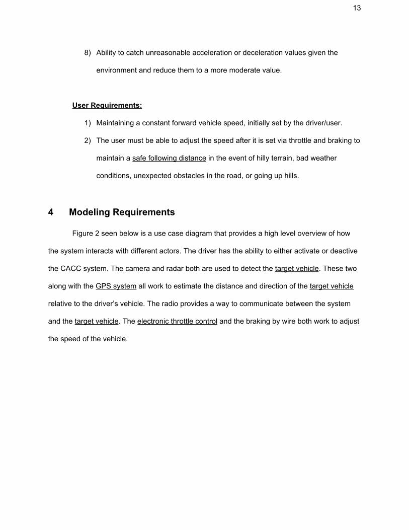
8) Ability to catch unreasonable acceleration or deceleration values given the
environment and reduce them to a more moderate value.
User Requirements:
1) Maintaining a constant forward vehicle speed, initially set by the driver/user.
2) The user must be able to adjust the speed after it is set via throttle and braking to
maintain a safe following distance in the event of hilly terrain, bad weather
conditions, unexpected obstacles in the road, or going up hills.
4 Modeling Requirements
Figure 2 seen below is a use case diagram that provides a high level overview of how
the system interacts with different actors. The driver has the ability to either activate or deactive
the CACC system. The camera and radar both are used to detect the target vehicle. These two
along with the GPS system all work to estimate the distance and direction of the target vehicle
relative to the driver’s vehicle. The radio provides a way to communicate between the system
and the target vehicle. The electronic throttle control and the braking by wire both work to adjust
the speed of the vehicle.

14
Figure 2: Use case diagram showing the interactions of the system
Figure 3 is a UML class diagram that provides a high level overview of the key elements of the
system. Following the UML diagram are data dictionaries that further describes each class, its
attributes and methods, and any relationships it has to another class.

15
Figure 3: Class diagram showing a high level overview of the system
Data Dictionary 1: Camera class
Element Name Description
Camera A class to handle the camera’s functionality and process the images.
Attributes
Operations
TakePicture (): void Takes a picture and adds it to the array of images used to identify target vehicles.

16
Relationships The Camera class has a 1 to 1 relationship with the CentralSystem and an array of up to 300 Images.
UML Extensions
Data Dictionary 2: CentralSystem class
Element Name Description
CentralSystem A class that handles the central functionality of the system. It coordinates all of the other sub-systems in the CACC.
Attributes
currentSpeed: int The current speed of the vehicle in mph.
expectedSpeed: int The calculated expected speed that the vehicle should be traveling at.
vehicleId: string Unique identifier to this vehicle.
weather: int Integer representing one of the various possible weather conditions that could be present.
envelope: int The vehicle’s envelope measured in G representing the acceleration abilities.
isActive: boolean The current status of if the CACC system is active or not.
Operations
Initialize (): void This method is called when the system is first activated and initializes all other sub-systems.
AdjustSpeed(): void Adjusts the speed by applying the brakes or the throttle until the currentSpeed matches expectedSpeed.
addTarget(vehicle: TargetVehicle) Adds the vehicle to the target array of vehicles.
removeTarget(vehicle: TargetVehicle)
Removes the vehicles from the target array of vehicles.

17
Activate(): void Activates cruise control when the user turns the system on.
Deactivate: void Turns cruise control off.
Relationships The CentralSystem has a one to one relationship with the GPSSystem, Camera, Radio, and Radar. It keeps track of a TargetVehicle called the leadTarget that represents the leader of the platoon. It keeps an array of up to 1 target representing the target vehicle in front of this vehicle.
UML Extensions
Data Dictionary 3: Image class
Element Name Description
Image A data structure to store an image in a bitmap.
Attributes image: int [6400000] An array of bits that represents the bitmap for a 800 x 800 pixel image.
Operations
Relationships The camera class contains an array of up to 300 Images.
UML Extensions
Data Dictionary 4: GPSSystem class
Element Name Description
GPSSystem Handles the GPS data for the vehicle.
Attributes
Operations

18
UpdateStatus(): void Gets the current GPS data for the vehicle including the speed, location and direction and updates those values of the vehicle.
Relationships The GPSSystem has a one to one relationship with the CentralSystem.
UML Extensions
Data Dictionary 5: Radar class
Element Name Description
Radar The Radar class represents the radar system that scans around the vehicle.
Attributes
Operations
getTargetVehicle(): void Uses the radar images detect a target vehicle and get the speed of the target vehicle.
Relationships Radar has a one to one relationship with the CentralSystem
UML Extensions
Data Dictionary 6: Radio class
Element Name Description
Radio The Radio class handles all of the radio communication to and from the vehicle.
Attributes
Operations
SendInfo(): void Broadcasts the vehicles GPS information and packet information to other vehicles in the platoon.

19
ProcessInfo(): void Receives a broadcast from another vehicle and processes the information to update that vehicles info.
Relationships Radio has a one to one relationship with the CentralSystem
UML Extensions
Data Dictionary 7: TargetVehicle class
Element Name Description
TargetVehicle The TargetVehicle class represents a target vehicle
Attributes
id: string Unique identifier of the vehicle
speed: int The speed of the vehicle in mph
direction: int The direction that the vehicle is traveling repesented by an integer that is how many degrees the direction differs from traveling directly north
Operations
Relationships The TargetVehicle is kept track of by the CentralSystem as an array of targets. It is also held seperately as a leadTargetVehicle by the CentralSystem representing the lead vehicle of the platoon.
UML Extensions
Scenarios:
The following figures are sequence diagrams. These diagrams symbolize how different
systems react to changes in circumstance. Sequence is represented by vertical position,
beginning with the top and moving downward.
20
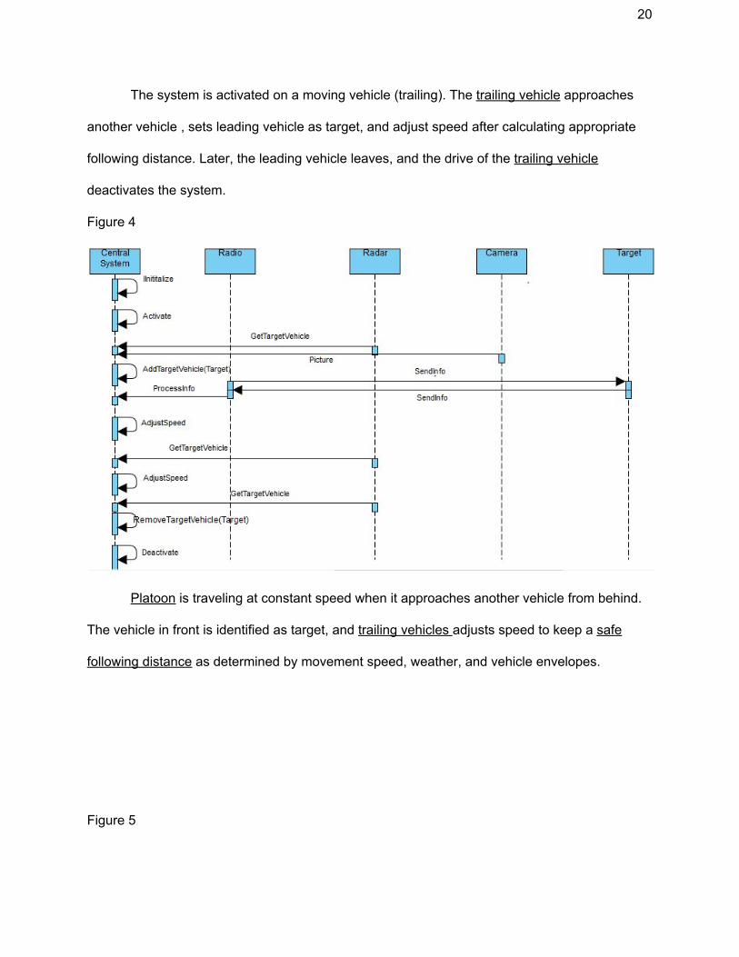
The system is activated on a moving vehicle (trailing). The trailing vehicle approaches
another vehicle , sets leading vehicle as target, and adjust speed after calculating appropriate
following distance. Later, the leading vehicle leaves, and the drive of the trailing vehicle
deactivates the system.
Figure 4
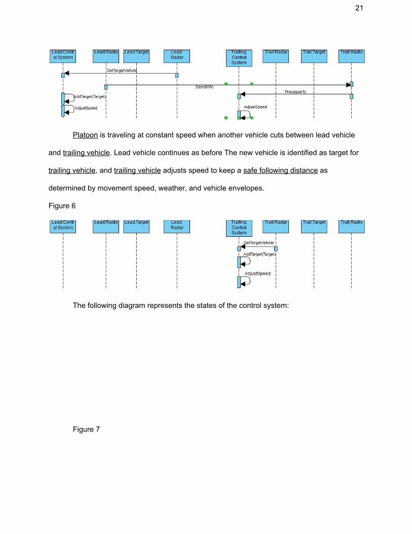
Platoon is traveling at constant speed when it approaches another vehicle from behind.
The vehicle in front is identified as target, and trailing vehicles adjusts speed to keep a safe
following distance as determined by movement speed, weather, and vehicle envelopes.
Figure 5
21
Platoon is traveling at constant speed when another vehicle cuts between lead vehicle
and trailing vehicle. Lead vehicle continues as before The new vehicle is identified as target for
trailing vehicle, and trailing vehicle adjusts speed to keep a safe following distance as
determined by movement speed, weather, and vehicle envelopes.
Figure 6
The following diagram represents the states of the control system:
Figure 7

22
5 Prototype
The prototype will be used to demonstrate the different conditions the system is to run
properly under. The prototype will demonstrate the functionality under various weather
conditions, while driving on curves, on different terrains, and with changes to the platoon.
5.1 How to Run Prototype
The prototype will be run on the website using Javascript, JQuery, CSS and HTML.
Selections in several dropdowns will create different scenarios that the prototype will resemble.
Prototype v1 will not be dynamic but will allow the user to select different options for the
overall system. The platoon and the safe following distance will be displayed both in terms of
seconds as well as in terms of distance in feet. Prototype v2 will be dynamic reacting to the user
changes in the system options. The platoon and safe following distance will continue to be
displayed but the vehicle will move relative to the target vehicle based on the conditions.
5.2 Sample Scenarios
23
The system must be safe and reliable under several conditions. The major parameter
that needs to be monitored and updated is the safe following distance. The other parameter that
must dynamically change effectively is the management of the platoon. Thus, the prototype will
allow the user to run the system under different weather conditions such as rain or snow. The
prototype will demonstrate these scenarios by creating more space between the cars, as well as
displaying the safe following distance in both seconds and feet. The prototype will demonstrate
which vehicle is the target vehicle properly maintaining said vehicle on curves. The prototype
will also demonstrate what happens to the platoon if another vehicle merges between the
vehicles in the platoon.
6 References
[1] D. Thakore and S. Biswas, “Routing with Persistent Link Modeling in Intermittently
Connected Wireless Networks,” Proceedings of IEEE Military Communication, Atlantic City,
October 2005.
7 Point of Contact
For further information regarding this document and project, please contact Prof. Betty
H.C. Cheng at Michigan State University (chengb at cse.msu.edu). All materials in this
document have been sanitized for proprietary data. The students and the instructor gratefully
acknowledge the participation of our industrial collaborators.
Related Documents