System Requirements Operating System: Win7/ Win10, Windows Server 2012/2016/2018, hyper V Processor Server: Intel® Pentium® and above Installed Memory (RAM): min. 8GB Hard Disk: 80GB of free space Built-in USB transmission interface Software Download SOYAL Website SOYAL Software Series V211013 Software Manual SOR Tools

Welcome message from author
This document is posted to help you gain knowledge. Please leave a comment to let me know what you think about it! Share it to your friends and learn new things together.
Transcript

System Requirements
Operating System: Win7/ Win10, Windows Server 2012/2016/2018, hyper V
Processor Server: Intel® Pentium® and above
Installed Memory (RAM): min. 8GB
Hard Disk: 80GB of free space
Built-in USB transmission interface
Software DownloadSOYAL Website
SOYAL Software SeriesV211013
Software Manual
SOR Tools
06
13
14
15
16
17
01
03
SOR Authorization Card Setting
Enable SOR Controller
1
2
3
4
Format SOR Card
Editing Formatted Card
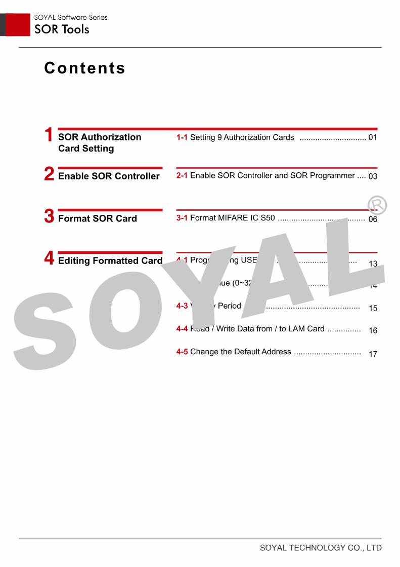
3-1 Format MIFARE IC S50 .......................................
4-1 Programming USER ID ....................................
4-2 Card Value (0~32767) .......................................
4-3 Validity Period ....................................................
4-4 Read / Write Data from / to LAM Card ...............
4-5 Change the Default Address ..............................
2-1 Enable SOR Controller and SOR Programmer ....
1-1 Setting 9 Authorization Cards ..............................
Contents
SOYAL Software Series
SOR Tools
SOYAL TECHNOLOGY CO., LTD

Using Authorization Cards to save password (Key A/ Key B) and to set the
permissions to strengthen the password the confidentiality. Authorization card is a
very important, please keep these cards in a safe place.
Th following example can help you get familiar with Key A / Key B of SIM.
Example : SIM Card Key A / Key B Setting
(Setting KeyA / KeyB and Config in MIFAREKEY software and write to SIM card block 16 and block 17)
1
2
3
4
56
1. SOR Authorization Card Setting
1. SOR Authorization Card Setting
Setting of 9 Authorization Cards1-1
SOYAL Software Series
SOR Tools
SOYAL TECHNOLOGY CO., LTD 01

After the setting is completed, Key A & Key B will be stored in this SIM card. You can use this SIM card for setting the SOR function. Please follow the same procedures to store Key A & Key B in CIM/UIM cards.※ Please keep one of each authorization card in a safe place in case some of them are lost or damaged.
Note:
STEP 1 : Close all other SOYAL software first. Then, connect AR-737P to the PC and launch SOR Tools software.STEP 2 : Select "Key A/B Functions" and click "Connect to Device". STEP 3 : Selection COM Port.STEP 4 : Selection controller item No. For example: AR-725-PSTEP 5 : Click "Connect" button.STEP 6 : "Connected" will be shown in the window, that means the connection is successful.STEP 7 : Place SIM card on the surface of AR-725-PSTEP 8 : Click "Setup Key A/B". (To write data to SIM Block)STEP 9 : Input the desired Key A/ Key B. (Key A = 12-digit hexadecimal value, Key B = 12-digit hexadecimal value).STEP 10 : Select "16" in "KeyA + KeyB + KeyA(Read/Dec) + KeyB(Write/Inc)" field, and click "Write"button. (Read/Decrement: Key A. Write/Increment: Key B. Write the data to Block 16 of theSIM card)STEP 11 : Select "17" in "KeyA + KeyB + KeyA(Read/Dec) + KeyA(Write/Inc)" field, and click "Write"button. (Read/Decrement: Key A. Write/Increment: Key A. Write the data to Block 17 of the SIM card)
8
9
1011
1. SOR Authorization Card Setting SOYAL Software Series
SOR Tools
SOYAL TECHNOLOGY CO., LTD02

You can use SIM or UIM to enable the SOR function of Mifare access controllers. Please follow the procedures:
Example : Enable the SOR function of AR-727HD by UIM Card
(Reading Key A from UIM card block 16 and write to AR-727H 00 block)
1
2
3
45 6
2. Enable SOR Controller
2. Enable SOR Controller
Enable SOR Controller2-1
SOYAL Software Series
SOR Tools
SOYAL TECHNOLOGY CO., LTD 03

STEP 1 : Close all other SOYAL software first. Then, connect AR-727HD to the PC and launch SOR Tools software.STEP 2 : Select "Authorization" and click "Connect to Device".STEP 3 : Select COM Port.STEP 4 : Select Device and Node ID. (AR-727-E).STEP 5 : Click "Connect" button.STEP 6 : "Connected" will be shown in the window, that means the connection is successful.STEP 7 : Place UIM card to on the surface of the AR-727-E.
STEP 8 : Select "SIM/UIM/CIM Functions".STEP 9 : Click "Read Card" button to view the information of the UIM card.STEP 10 : Click "Transfer" button in "Transfer Key A,B from SIM/CIM/UIM to Device Key Buffer" field.Key A stored in block 16 of the UIM card will be copied to block 00 of the AR-727-E.
89
10
2. Enable SOR ControllerSOYAL Software Series
SOR Tools
SOYAL TECHNOLOGY CO., LTD04

After the setting is completed, the Key A has been stored in AR-727-E and the SOR function has also been enabled. This AR-727-E is able to read SOR cards with the same Key A.
Note:
STEP 11 : Select "Device Functions" and click "Launch Device".STEP 12 : Tick "Enable SOR". STEP 13 : Click "Launch" button.
11
12
13
2. Enable SOR ControllerSOYAL Software Series
SOR Tools
SOYAL TECHNOLOGY CO., LTD 05

3. Format SOR Card
3. Format SOR Card
Format MIFARE IC S503-1
The default values of Key A & Key B in brand-new MIFARE IC S50 card are both FFFF
FFFF FFFF (F*12) and the default Config Trailer is A: Decrement A: Increment. There are
16 sectors in the EEPROM of MIFARE IC S50. Each sector contains 4 blocks, and the last
block of each sector is called “trailer”, which contains two secret keys and programmable
access conditions for each block in this sector. Thus, all blocks of trailers cannot be written
in other data. The following is the list of blocks which are NOT recommended for writing
data.
1. Block 00 (Read-only Manufacturer block): it contains the IC manufacturer data
(for example, UID) and is programmed and write protected in the production test.
2. All blocks of trailers (block 03, 07, 11, 15, 19, 23, 27, 31, 35, 39, 43, 47, 51, 55, 59,
and 63).
3. All blocks in Sector 01/02/03: they are reserved for SOR.
4. All blocks in Sector 14/15: they are reserved for the event logs.
The memory organization of EEPROM of MIFARE IC S50 is shown in the chart of page 7:
SOYAL Software Series
SOR Tools
SOYAL TECHNOLOGY CO., LTD06

Example : Copy Key A / Key B of CIM Card to AR-725-P & PC Buffer
(Copy Key A & Key B in bolck 16 of the CIM card to device key 00 & 01 (AR-725-P).)
(Copy Block 16 & Block 17 of the CIM card to TMP Buffer 00 & TMP Buffer 01 in the PC.)
3. Format SOR CardSOYAL Software Series
SOR Tools
SOYAL TECHNOLOGY CO., LTD 07

STEP 1 : Close all other SOYAL software first. Then, connect AR-725-P to the PC and launch SOR Tools software.STEP 2 : Select "Authorization" and click "Connect to Device". STEP 3 : Select COM Port.STEP 4 : Select Device (AR-725-P).STEP 5 : Click "Connect" button.STEP 6 : "Connected" will be shown in the window, that means the connection is successful.STEP 7 : Place CIM card to on the surface of the AR-725-P.
1
2
3
4
56
3. Format SOR CardSOYAL Software Series
SOR Tools
SOYAL TECHNOLOGY CO., LTD08

After the setting is completed, Key A & Key B will be stored in both AR-725-P and PC TMP
buffer, so you can remove the CIM card from AR-725-P.
Note:
STEP 8 : Select "SIM/UIM/CIM Functions".STEP 9 : Click "Read Card" to view the information of the CIM card.STEP 10 : Click "Transfer" button in "Transfer Data from SIM/CIM/UIM to Configure Buffer for FormatTAG usage" field. Block 16 of the CIM card will be copied to TMP buffer (00) and block 17 of the CIM card will be copied to TMP buffer (01).STEP 11 : In "Transfer Key A,B from SIM/CIM/UIM to Device Key Buffer" field: Source Data Block: 16 (Copy the Key A/B stored in block 16 of the CIM card). Key A: 00 (Copy Key A to key 00 of the device (AR-725-P)) Key B: 01 (Copy Key B to key 01 of the device (AR-725-P)) Then, click "Transfer" button.
8
9
10
11
3. Format SOR CardSOYAL Software Series
SOR Tools
SOYAL TECHNOLOGY CO., LTD 09

Example : Use CIM Card to Format MIFARE IC S50
(Use TMP Buffer value to reset Key A / Key B & Config of each sector in the new card.)
2
3 4 5 6
7
3. Format SOR CardSOYAL Software Series
SOR Tools
SOYAL TECHNOLOGY CO., LTD10
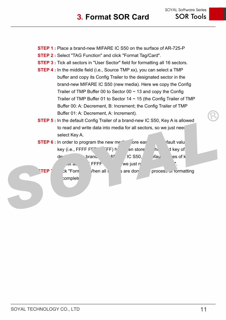
STEP 1 : Place a brand-new MIFARE IC S50 on the surface of AR-725-PSTEP 2 : Select "TAG Function" and click "Format Tag/Card". STEP 3 : Tick all sectors in "User Sector" field for formatting all 16 sectors.STEP 4 : In the middle field (i.e., Source TMP xx), you can select a TMP buffer and copy its Config Trailer to the designated sector in the brand-new MIFARE IC S50 (new media). Here we copy the Config Trailer of TMP Buffer 00 to Sector 00 ~ 13 and copy the Config Trailer of TMP Buffer 01 to Sector 14 ~ 15 (the Config Trailer of TMP Buffer 00: A: Decrement, B: Increment; the Config Trailer of TMP Buffer 01: A: Decrement, A: Increment).STEP 5 : In the default Config Trailer of a brand-new IC S50, Key A is allowed to read and write data into media for all sectors, so we just need to select Key A.STEP 6 : In order to program the new media more easily, the default value of key (i.e., FFFF FFFF FFFF) has been stored in the 32nd key of device. In the brand-new MIFARE IC S50, all default values of keys are set as FFFF FFFF FFFF, so we just need to select "32".STEP 7 : Click "Format". When all sectors are done, the process of formatting is completed.
3. Format SOR CardSOYAL Software Series
SOR Tools
SOYAL TECHNOLOGY CO., LTD 11

After the formatting process is completed, you can proceed to edit the data in this
formatted card.
1. Programming USER ID
2. Card Value (0~32767)
3. Two sets of Validity Period
4. Read/Write Data from/to LAM Card
5. Change the Default Address
After completing the above operations, it must press Launch button to write
data to card, and also must confirm whether the message status bar shows
write OK to ensure all data setting is definitely complete
Note:
4. Edit Formatted Card
4. Edit Formatted Card
SOYAL Software Series
SOR Tools
SOYAL TECHNOLOGY CO., LTD12

The UID of Mifare card is not sequential by factory default. When you
purchase a batch of Mifare cards, the non-sequential card ID will somehow
cause inconvenience for management. To solve this problem, SOR provides
the function of assigning a new User ID to this Mifare card and make the
management more convenient. If you don’t want to assign a new User ID, you
still have to input the original User ID (card ID) in "UserID [Site:User]" field or
the SOR access controller cannot read this card. Generally, we use WG format
of User ID: 5-digit site code + 5-digit card code (both site code & card code
cannot exceed 65,535).
STEP 1 : Select "TAG Functions" and click "Launch LAM".STEP 2 : Input 5-digit site code and 5-digit card code. STEP 3 : Click "Write".
1
2
4. Edit Formatted Card
Programming USER ID4-1
SOYAL Software Series
SOR Tools
SOYAL TECHNOLOGY CO., LTD 13

Card value must be an integer and should be less than 32,767.
1
2
3
STEP 1 : Select "TAG Functions" and click "Launch LAM".STEP 2 : Input value. STEP 3 : Click "Write" button.
Card Value (0~32767)4-2
4. Edit Formatted CardSOYAL Software Series
SOR Tools
SOYAL TECHNOLOGY CO., LTD14

You can designate two sets of expiry date of this card.
STEP 1 : Select "TAG Functions" and click "Launch LAM".STEP 2 : Input begin date/time and expiry date/time. STEP 3 : Click "Write" button.
12
3
Validity Period4-3
4. Edit Formatted CardSOYAL Software Series
SOR Tools
SOYAL TECHNOLOGY CO., LTD 15

This is the best feature of this SOR Tools software (Mifare Key doesn't possess this
feature). If you know the Key A & Key B of the LAM card, you can read/write data
from/to blocks of the LAM card.
STEP 1 : Select "TAG Functions" and click "Block Read/Write Function".STEP 2 : Select the desired block. STEP 3 : Click "Read" to read data from this block.STEP 4 : Click "Write" to wtite data to this block.
1
2
34
Read / Write Data from / to LAM Card4-4
4. Edit Formatted CardSOYAL Software Series
SOR Tools
SOYAL TECHNOLOGY CO., LTD16

The default block address for storing User ID is block 09 (in Sector 02). The
default block address for storing the 2 sets of validity period is block 12 & 13 (in
Sector 03). Since Key A has been stored in key 00 of the device (AR-725-P),
Key B has been stored in key 01 of the device (AR-737P), and Config Trailer
is set as A: Decrement (Read) B: Increment (Write), we select "00" (Key A) in
"Read KEY" field and "01" (Key B) in "Write KEY" field.
STEP 1 : Select "TAG Functions" and click "Launch LAM".STEP 2 : Select the value of "Read KEY" & "Write KEY". STEP 3 : Click "Launch All" button.
1
2
3
After SIM card load Key A and Key B into the Device Key, and then placed the formatted card
on AR-725-P again, the software will display the formatted card as LAN card, that means that
the card has been formatted.
Note:
Change the Default Block Address4-5
4. Edit Formatted Card
Youtube: 《SOR MIFARE Programming》SOR Tools & MIFARE Key Features Guide
SOYAL Software Series
SOR Tools
SOYAL TECHNOLOGY CO., LTD 17
Related Documents