Software Implementation of WiMAX on the Sandbridge SandBlaster Platform Daniel Iancu 1 , Hua Ye 1 , Emanoil Surducan 1 , Murugappan Senthilvelan 1 , John Glossner 1,2 , Vasile Surducan 1 , Vladimir Kotlyar 1 , Andrei Iancu 1 , Gary Nacer 1 , and Jarmo Takala 1 Sandbridge Technologies, One North Lexington Ave., White Plains, NY 10601, USA [diancu, huaye, esurducan, msenthilvelan, jglossner, vsurducan, vkoltyar, aiancu, gnacer]@sandbridgetech.com 2 Delft University of Technology, Computer Engineering, EE, Delft, The Netherlands 3 Tampere University of Technology, Tampere, Finland [email protected] Abstract. This paper describes a Sandbridge Sandblaster system implementa- tion including both hardware and software elements for a WiMax 802.16e system. The system is implemented on the fully functional multithreaded Sandblaster multiprocessor SB3010 SoC chip. The entire communication protocol, physical layer and MAC, has been implemented in software using pure ANSI C program- ming language and it executes in real time. In this paper, we also present a radio propagation analysis specific to the Samos island at the workshop location, and the DSP execution performance. 1 Introduction Wimax [1] is a long range, fixed, portable, or mobile wireless technology specified in the IEEE 802.16 standard. It provides high-throughput broadband connections similar to 802.11 wireless LAN systems but with much larger range. Possible applications for WiMAX include: ”last mile” broadband connections, hotspot and cellular backhaul, and high-speed enterprise connectivity for busines. Since the IEEE 802.16 standard de- fines a Media Access Control (MAC) layer that supports different physical layers and also defines the same Logical Layer Control (LLC) level l for different Local and Wide Area Networks (LAN and WAN), it opens up the possibility of bridging different com- munication networks together. A common MAC allows multi-mode and multi-radios easier implementations and at the same time it also simplifies system management and roaming issues. A multi-mode multi-radio system has historically been implemented using either multiple separate chip sets or specific System on Chip (SoC) solutions with replicated internal hardware. Recently, a more cost effective approach has gained in popularity. A Software Defined Radio (SDR) implements all of the physical layer in software and is capable of dynamically switching waveform execution and thus reusing existing silicon resources. Our WiMAX implementation described in this paper, is an SDR solution.

Welcome message from author
This document is posted to help you gain knowledge. Please leave a comment to let me know what you think about it! Share it to your friends and learn new things together.
Transcript
Software Implementation of WiMAX on the SandbridgeSandBlaster Platform
Daniel Iancu1, Hua Ye1, Emanoil Surducan1, Murugappan Senthilvelan1, JohnGlossner1,2, Vasile Surducan1, Vladimir Kotlyar1, Andrei Iancu1, Gary Nacer1, and
Jarmo Takala
1 Sandbridge Technologies, One North Lexington Ave., White Plains, NY 10601, USA[diancu, huaye, esurducan, msenthilvelan, jglossner, vsurducan, vkoltyar,
aiancu, gnacer]@sandbridgetech.com2 Delft University of Technology, Computer Engineering, EE, Delft, The Netherlands
3 Tampere University of Technology, Tampere, Finland [email protected]
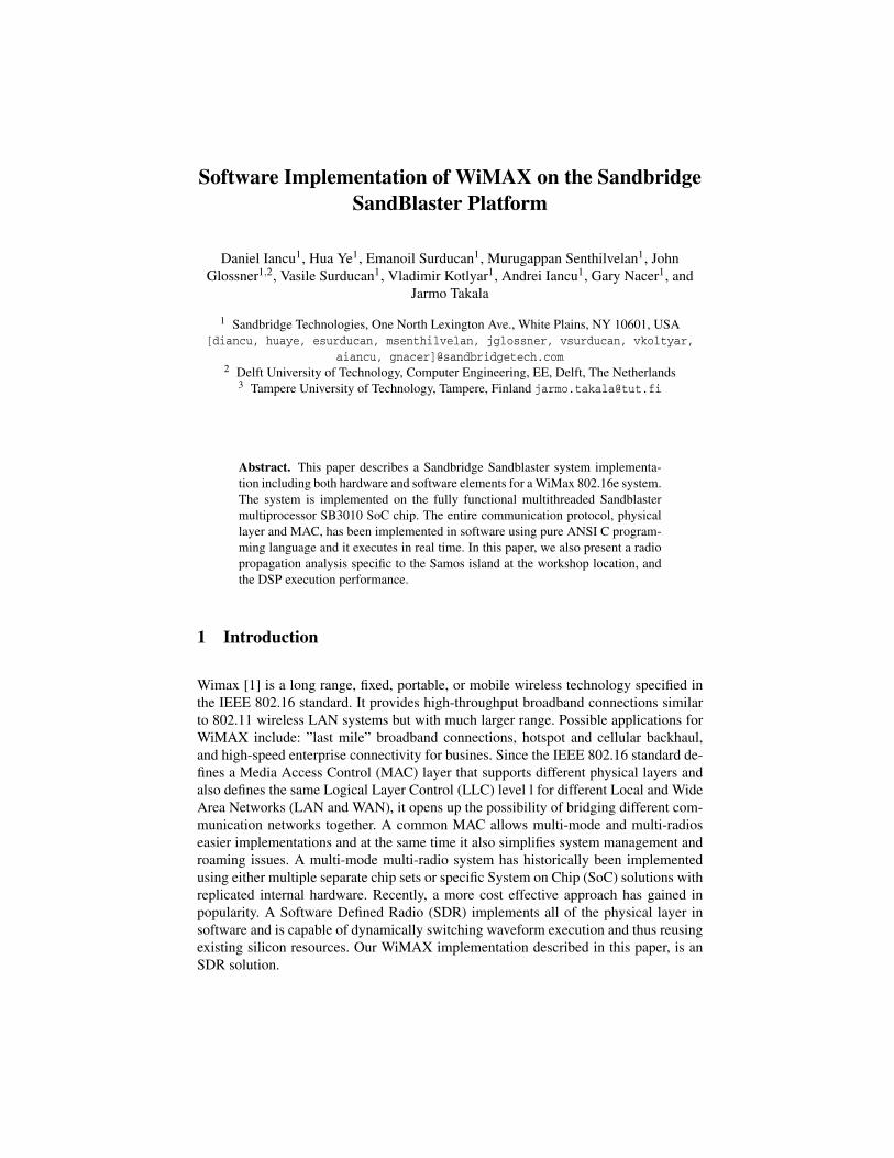
Abstract. This paper describes a Sandbridge Sandblaster system implementa-tion including both hardware and software elements for a WiMax 802.16e system.The system is implemented on the fully functional multithreaded Sandblastermultiprocessor SB3010 SoC chip. The entire communication protocol, physicallayer and MAC, has been implemented in software using pure ANSI C program-ming language and it executes in real time. In this paper, we also present a radiopropagation analysis specific to the Samos island at the workshop location, andthe DSP execution performance.
1 Introduction
Wimax [1] is a long range, fixed, portable, or mobile wireless technology specified inthe IEEE 802.16 standard. It provides high-throughput broadband connections similarto 802.11 wireless LAN systems but with much larger range. Possible applications forWiMAX include: ”last mile” broadband connections, hotspot and cellular backhaul,and high-speed enterprise connectivity for busines. Since the IEEE 802.16 standard de-fines a Media Access Control (MAC) layer that supports different physical layers andalso defines the same Logical Layer Control (LLC) level l for different Local and WideArea Networks (LAN and WAN), it opens up the possibility of bridging different com-munication networks together. A common MAC allows multi-mode and multi-radioseasier implementations and at the same time it also simplifies system management androaming issues. A multi-mode multi-radio system has historically been implementedusing either multiple separate chip sets or specific System on Chip (SoC) solutions withreplicated internal hardware. Recently, a more cost effective approach has gained inpopularity. A Software Defined Radio (SDR) implements all of the physical layer insoftware and is capable of dynamically switching waveform execution and thus reusingexisting silicon resources. Our WiMAX implementation described in this paper, is anSDR solution.
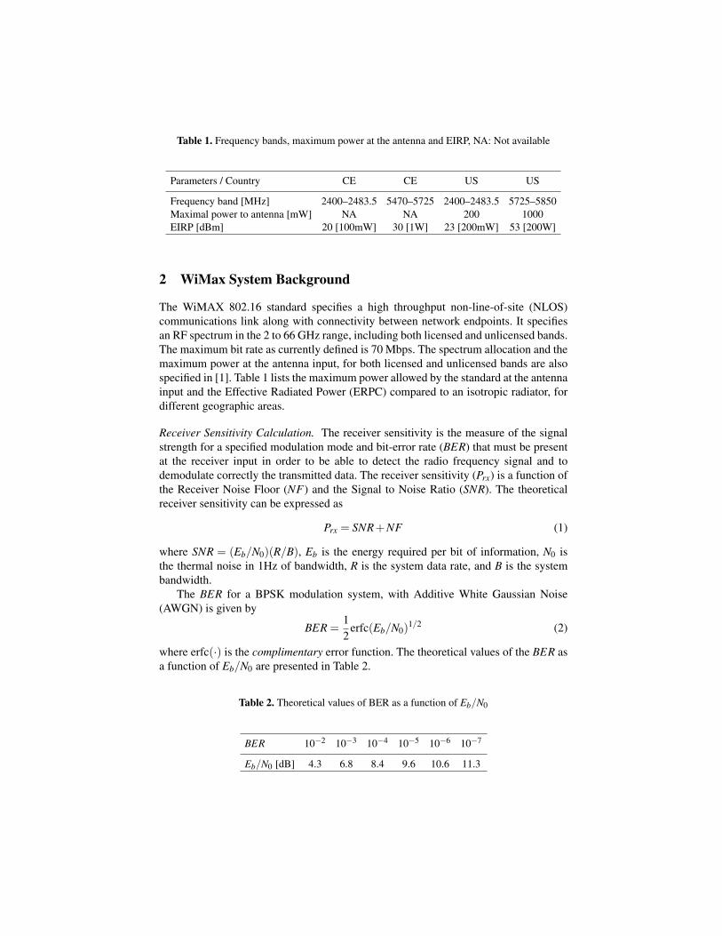
Table 1. Frequency bands, maximum power at the antenna and EIRP, NA: Not available
Parameters / Country CE CE US US
Frequency band [MHz] 2400–2483.5 5470–5725 2400–2483.5 5725–5850Maximal power to antenna [mW] NA NA 200 1000EIRP [dBm] 20 [100mW] 30 [1W] 23 [200mW] 53 [200W]
2 WiMax System Background
The WiMAX 802.16 standard specifies a high throughput non-line-of-site (NLOS)communications link along with connectivity between network endpoints. It specifiesan RF spectrum in the 2 to 66 GHz range, including both licensed and unlicensed bands.The maximum bit rate as currently defined is 70 Mbps. The spectrum allocation and themaximum power at the antenna input, for both licensed and unlicensed bands are alsospecified in [1]. Table 1 lists the maximum power allowed by the standard at the antennainput and the Effective Radiated Power (ERPC) compared to an isotropic radiator, fordifferent geographic areas.
Receiver Sensitivity Calculation. The receiver sensitivity is the measure of the signalstrength for a specified modulation mode and bit-error rate (BER) that must be presentat the receiver input in order to be able to detect the radio frequency signal and todemodulate correctly the transmitted data. The receiver sensitivity (Prx) is a function ofthe Receiver Noise Floor (NF) and the Signal to Noise Ratio (SNR). The theoreticalreceiver sensitivity can be expressed as
Prx = SNR+NF (1)
where SNR = (Eb/N0)(R/B), Eb is the energy required per bit of information, N0 isthe thermal noise in 1Hz of bandwidth, R is the system data rate, and B is the systembandwidth.
The BER for a BPSK modulation system, with Additive White Gaussian Noise(AWGN) is given by
BER =12
erfc(Eb/N0)1/2 (2)
where erfc(·) is the complimentary error function. The theoretical values of the BER asa function of Eb/N0 are presented in Table 2.
Table 2. Theoretical values of BER as a function of Eb/N0
BER 10−2 10−3 10−4 10−5 10−6 10−7
Eb/N0 [dB] 4.3 6.8 8.4 9.6 10.6 11.3
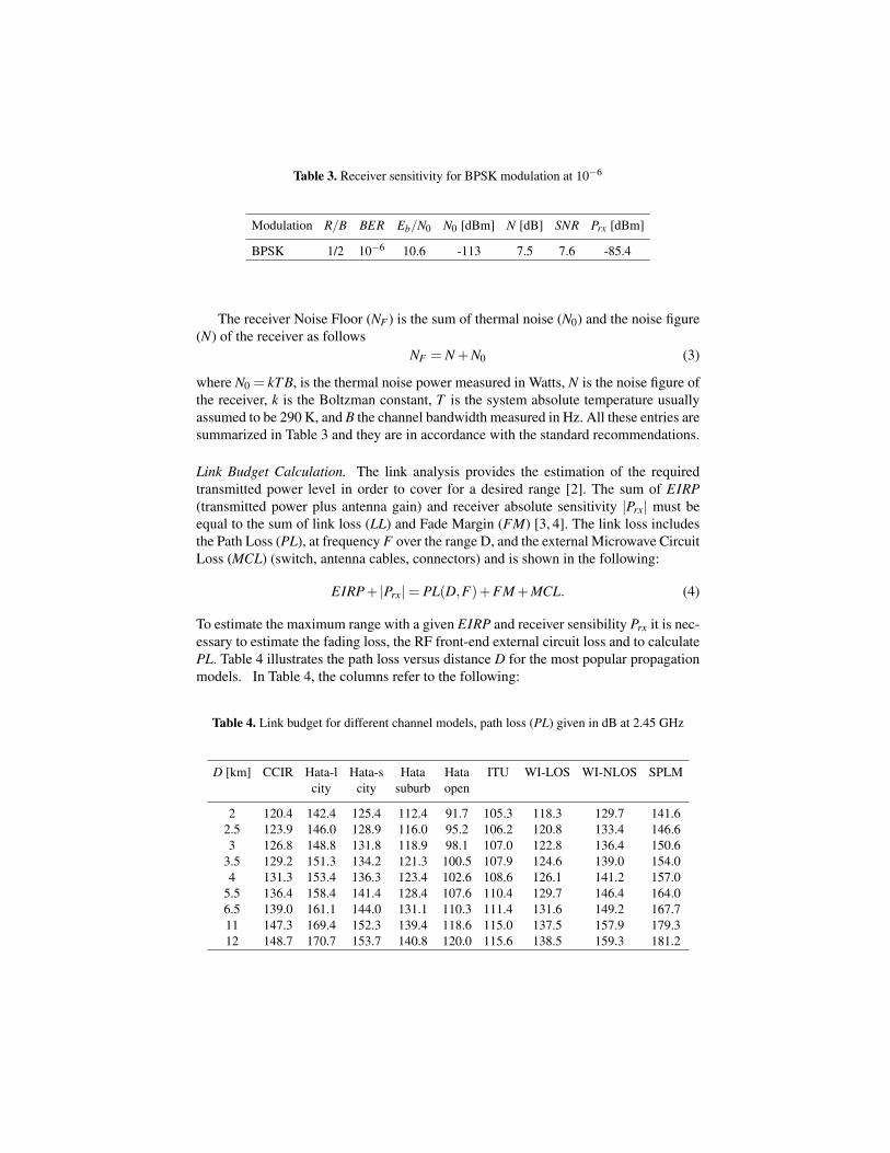
Table 3. Receiver sensitivity for BPSK modulation at 10−6
Modulation R/B BER Eb/N0 N0 [dBm] N [dB] SNR Prx [dBm]
BPSK 1/2 10−6 10.6 -113 7.5 7.6 -85.4
The receiver Noise Floor (NF ) is the sum of thermal noise (N0) and the noise figure(N) of the receiver as follows
NF = N +N0 (3)
where N0 = kT B, is the thermal noise power measured in Watts, N is the noise figure ofthe receiver, k is the Boltzman constant, T is the system absolute temperature usuallyassumed to be 290 K, and B the channel bandwidth measured in Hz. All these entries aresummarized in Table 3 and they are in accordance with the standard recommendations.
Link Budget Calculation. The link analysis provides the estimation of the requiredtransmitted power level in order to cover for a desired range [2]. The sum of EIRP(transmitted power plus antenna gain) and receiver absolute sensitivity |Prx| must beequal to the sum of link loss (LL) and Fade Margin (FM) [3, 4]. The link loss includesthe Path Loss (PL), at frequency F over the range D, and the external Microwave CircuitLoss (MCL) (switch, antenna cables, connectors) and is shown in the following:
EIRP+ |Prx| = PL(D,F)+FM +MCL. (4)
To estimate the maximum range with a given EIRP and receiver sensibility Prx it is nec-essary to estimate the fading loss, the RF front-end external circuit loss and to calculatePL. Table 4 illustrates the path loss versus distance D for the most popular propagationmodels. In Table 4, the columns refer to the following:
Table 4. Link budget for different channel models, path loss (PL) given in dB at 2.45 GHz
D [km] CCIR Hata-l Hata-s Hata Hata ITU WI-LOS WI-NLOS SPLMcity city suburb open
2 120.4 142.4 125.4 112.4 91.7 105.3 118.3 129.7 141.62.5 123.9 146.0 128.9 116.0 95.2 106.2 120.8 133.4 146.63 126.8 148.8 131.8 118.9 98.1 107.0 122.8 136.4 150.6
3.5 129.2 151.3 134.2 121.3 100.5 107.9 124.6 139.0 154.04 131.3 153.4 136.3 123.4 102.6 108.6 126.1 141.2 157.0
5.5 136.4 158.4 141.4 128.4 107.6 110.4 129.7 146.4 164.06.5 139.0 161.1 144.0 131.1 110.3 111.4 131.6 149.2 167.711 147.3 169.4 152.3 139.4 118.6 115.0 137.5 157.9 179.312 148.7 170.7 153.7 140.8 120.0 115.6 138.5 159.3 181.2
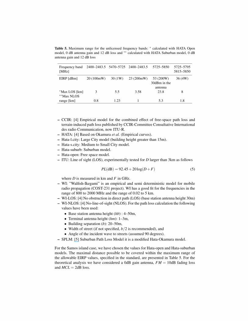
Table 5. Maximum range for the unlicensed frequency bands: ∗ calculated with HATA Openmodel, 0 dB antenna gain and 12 dB loss and ∗∗ calculated with HATA Suburban model, 0 dBantenna gain and 12 dB loss
Frequency band 2400–2483.5 5470–5725 2400–2483.5 5725–5850 5725–5795[MHz] 5815–5850
EIRP [dBm] 20 (100mW) 30 (1W) 23 (200mW) 53 (200W) 36 (4W)30dBm in the
antenna∗Max LOS [km] 3 5.5 3.58 23.8 8∗∗Max NLOSrange [km] 0.8 1.23 1 5.3 1.8
– CCIR: [4] Empirical model for the combined effect of free-space path loss andterrain-induced path loss published by CCIR-Committee Consultative Internationaldes radio Communication, now ITU-R.
– HATA: [4] Based on Okamura et al. (Empirical curves).– Hata-l.city: Large City model (building height greater than 15m).– Hata-s.city: Medium to Small City model.– Hata-suburb: Suburban model.– Hata-open: Free space model.– ITU: Line of sight (LOS), experimentally tested for D larger than 3km as follows
PL(dB) = 92.45+20log(D+F) (5)
where D is measured in km and F in GHz.– WI: ”Walfish-Ikegami” is an empirical and semi deterministic model for mobile
radio propagation (COST-231 project). WI has a good fit for the frequencies in therange of 800 to 2000 MHz and the range of 0.02 to 5 km.
– WI-LOS: [4] No obstruction in direct path (LOS) (base station antenna height 30m)– WI-NLOS: [4] No-line-of-sight (NLOS). For the path loss calculation the following
values have been used:• Base station antenna height (hb) : 4–50m,• Terminal antenna height (hm): 1–3m,• Building separation (b): 20–50m,• Width of street (if not specified, b/2 is recommended), and• Angle of the incident wave to streets (assumed 90 degrees).
– SPLM: [5] Suburban Path Loss Model it is a modified Hata-Okamura model.
For the Samos island case, we have chosen the values for Hata-open and Hata-suburbanmodels. The maximal distance possible to be covered within the maximum range ofthe allowable EIRP values, specified in the standard, are presented in Table 5. For thetheoretical analysis we have considered a 0dB gain antenna, FM = 10dB fading lossand MCL = 2dB loss.
Manolates, h=330m
Kokkari, h=10m
Workshop site, h=10m
d=2200m
100
d=3800m
200
300
400
500
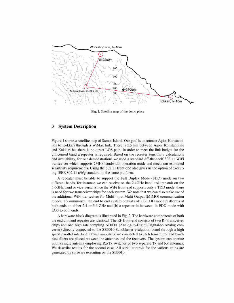
Fig. 1. Satellite map of the demo place
3 System Description
Figure 1 shows a satellite map of Samos Island. Our goal is to connect Agios Konstanti-nos to Kokkari through a WiMax link. There is 5.5 km between Agios Konstantinosand Kokkari but there is no direct LOS path. In order to meet the link budget for theunlicensed band a repeater is required. Based on the receiver sensitivity calculationsand availability, for our demonstrations we used a standard off-the-shelf 802.11 WiFitransceiver which supports 7MHz bandwidth operation mode and meets our estimatedsensitivity requirements. Using the 802.11 front-end also gives us the option of execut-ing IEEE 802.11 a/b/g standard on the same platform.
A repeater must be able to support the Full Duplex Mode (FDD) mode on twodifferent bands, for instance we can receive on the 2.4GHz band and transmit on the5.6GHz band or vice-versa. Since the WiFi front-end supports only a TDD mode, thereis need for two transceiver chips for each system. We note that we can also make use ofthe additional WiFi transceiver for Multi Input Multi Output (MIMO) communicationmodes. To summarize, the end to end system consists of: (a) TDD mode platforms atboth ends on either 2.4 or 5.6 GHz and (b) a repeater in between, in FDD mode withLOS to both ends.
A hardware block diagram is illustrated in Fig. 2. The hardware components of boththe end unit and repeater are identical. The RF front-end consists of two RF transceiverchips and one high rate sampling AD/DA (Analog-to-Digital/Digital-to-Analog con-verter) directly connected to the SB3010 Sandblaster evaluation board through a highspeed parallel interface. Power amplifiers are connected to each transmitter and band-pass filters are placed between the antennas and the receivers. The system can operatewith a single antenna employing Rx/Tx switches or two separate Tx and Rx antennas.We describe results for the second case. All serial controls for the various chips aregenerated by software executing on the SB3010.
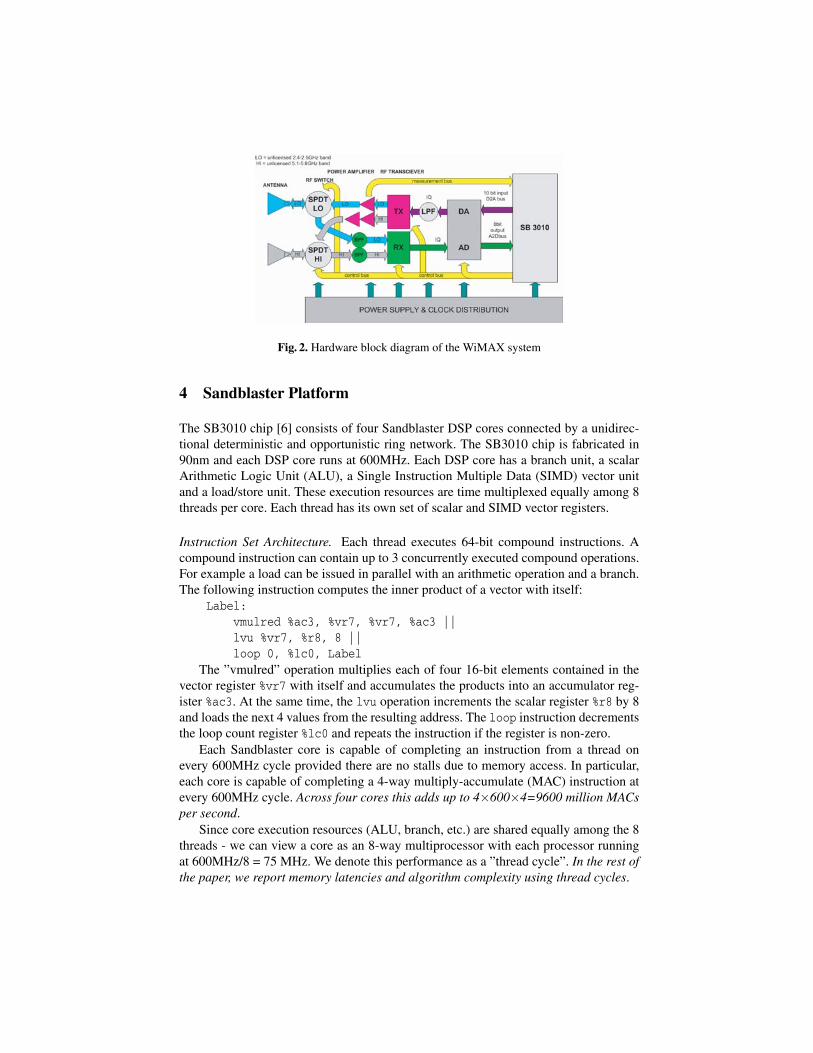
Fig. 2. Hardware block diagram of the WiMAX system
4 Sandblaster Platform
The SB3010 chip [6] consists of four Sandblaster DSP cores connected by a unidirec-tional deterministic and opportunistic ring network. The SB3010 chip is fabricated in90nm and each DSP core runs at 600MHz. Each DSP core has a branch unit, a scalarArithmetic Logic Unit (ALU), a Single Instruction Multiple Data (SIMD) vector unitand a load/store unit. These execution resources are time multiplexed equally among 8threads per core. Each thread has its own set of scalar and SIMD vector registers.
Instruction Set Architecture. Each thread executes 64-bit compound instructions. Acompound instruction can contain up to 3 concurrently executed compound operations.For example a load can be issued in parallel with an arithmetic operation and a branch.The following instruction computes the inner product of a vector with itself:
Label:vmulred %ac3, %vr7, %vr7, %ac3 ||lvu %vr7, %r8, 8 ||loop 0, %lc0, Label
The ”vmulred” operation multiplies each of four 16-bit elements contained in thevector register %vr7 with itself and accumulates the products into an accumulator reg-ister %ac3. At the same time, the lvu operation increments the scalar register %r8 by 8and loads the next 4 values from the resulting address. The loop instruction decrementsthe loop count register %lc0 and repeats the instruction if the register is non-zero.
Each Sandblaster core is capable of completing an instruction from a thread onevery 600MHz cycle provided there are no stalls due to memory access. In particular,each core is capable of completing a 4-way multiply-accumulate (MAC) instruction atevery 600MHz cycle. Across four cores this adds up to 4×600×4=9600 million MACsper second.
Since core execution resources (ALU, branch, etc.) are shared equally among the 8threads - we can view a core as an 8-way multiprocessor with each processor runningat 600MHz/8 = 75 MHz. We denote this performance as a ”thread cycle”. In the rest ofthe paper, we report memory latencies and algorithm complexity using thread cycles.
Memory Structure. Each core has a 32kB instruction cache. Data memory is not cachedand is divided between a 64kB Level 1 (L1) and 256 kB Level 2 (L2) memory. A loadfrom L2 memory incurs a pipeline stall. Stores into L2 are issued through a FIFO anddo not block unless the FIFO is full. In practice up to four threads can simultaneouslystore into L2 without blocking. The L1 memory is divided into 8 banks of 8kB each.A particular implementation detail is that there is no penalty if the parity (odd/even) ofthe thread is the same as the parity of the bank. There is a single cycle penalty bothfor loads and for stores if the parities of the thread and the bank do not match. Theinstruction in the inner product example will complete within a single thread cycle, ifit is executed on an even thread and %r8 points into an even bank. The compiler triesto ensure memory affinities and the processor tools can automatically generate linkerscripts that optimize memory access.
Programming Environment. The Sandblaster programming tools include: a supercomputer-class vectorizing compiler, a fast simulator, and real-time operating system (RTOS) thatimplements POSIX threads standard [7]. Our WiMax implementation is written entirelyin ANSI C using POSIX API for thread management. We rely on the optimizing com-piler to produce highly efficient machine code from straight-forward C source. Thecompiler automatically vectorizes most of the loops that occur in signal processing andmedia applications. It performs semantic analysis of input programs and automaticallyrecognizes saturating arithmetic in ANSI C [8]. For example the single-instruction loopfor an inner product is generated automatically from the following source:
int i, s;for (I = 0, s = 0; I < N; i++) {
s += A[k]*A[k];}
The Sandblaster simulator is capable of executing over 100 million instructions persecond on a 3GHz x86 computer [9]. The Sandblaster RTOS is capable of multiplexingan arbitrary number of software threads onto hardware threads. Software threads canbe designated as pinned or non-pinned. Pinned threads are removed from the generalthread scheduler and by convention, their stacks are allocated to L1 memory. Non-pinned threads can be rescheduled any time the operating system chooses and can beallocated based on the scheduling policy implemented in pthreads.
5 WiMAX Algorithms
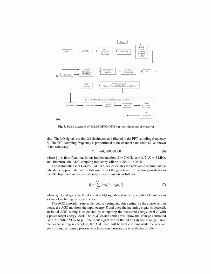
The physical layer transmitter pipeline for the OFDM PHY as specified in IEEE 802.16 [1]is shown in Fig. 3(a). The OFDM signaling format was selected in preference to com-peting formats such as single-carrier (SC) CDMA due to its superior multipath per-formance, permitting significant equalizer design simplification to support operation inNLOS fading environments.
Figure 3(b) shows the 802.16 OFDM PHY receiver block diagram. The back-endsignal processing block is the reverse of the transmitter pipeline shown in Fig. 3(a).Note that a Reed-Solomon (RS) decoder is not required for the 2.9 Mbps BPSK mode.
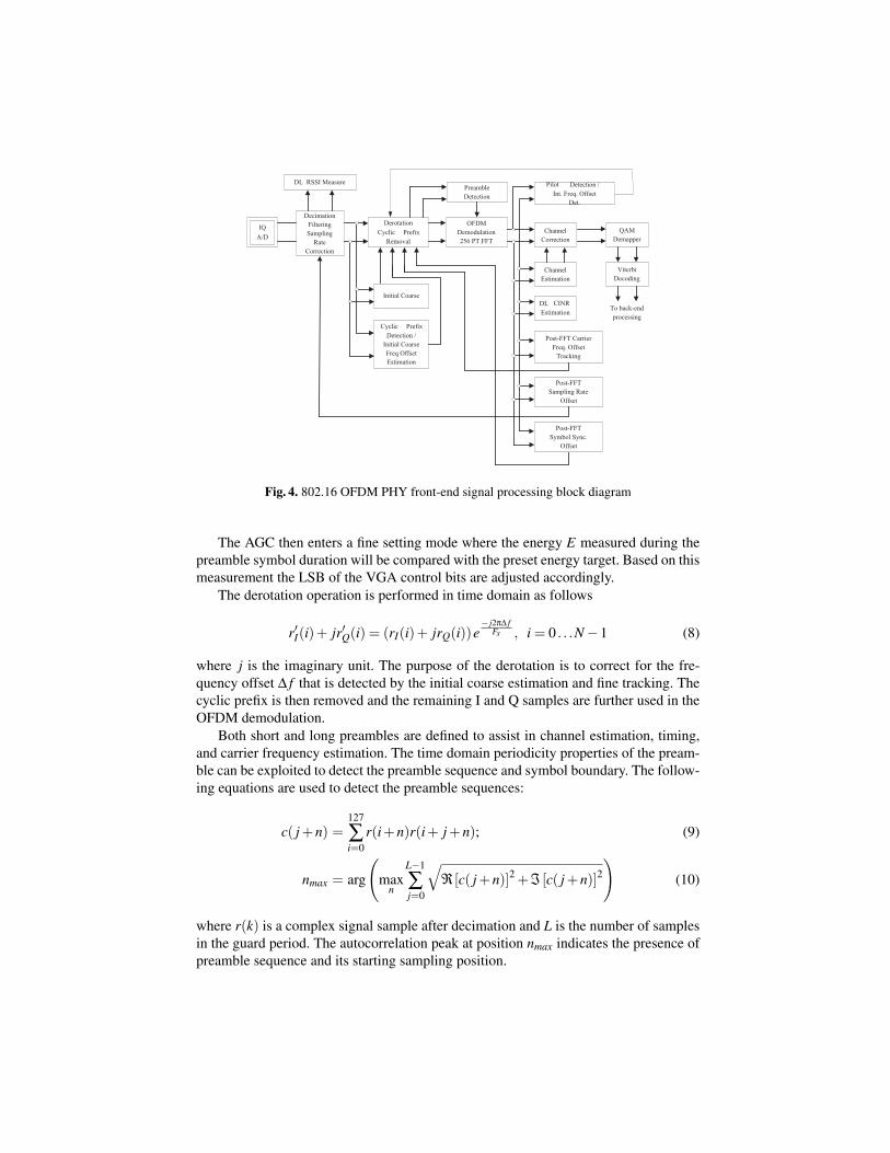
Figure 4 shows the 802.16 OFDM PHY front-end signal processing block diagram.The inputs to the A/D converter are the I and Q baseband signals coming from the RF
(a)
Scrambler FEC
Shorting Puncturing
PSDU Interleaver
BPSK QPSK
16 QAM 64 QAM Mapper
OFDM Modulation IFFT 256 pt
Cyclic Prefix Insertion
Filtering Upsampling DAC
Preamble
Pilots
(b)
Rx RFFront-End
Deinterleaver Depuncturer
Descrambler
ViterbiDecoder
Depuncturing/ Erasure
Generation
ErasureRS Decoder(255,239,8)
802.16 OFDM PHY Receiver Back-End Signal Processing Block
OFDM Demodulator(Receiver Front-End Signal Processing Block)
Fig. 3. Block diagrams of 802.16 OFDM PHY (a) transmitter and (b) receiver
chip. The I/Q signals are first 2:1 decimated and filtered to the FFT sampling frequencyFs. The FFT sampling frequency is proportional to the channel bandwidth (B) as shownin the following:
Fs = �nB/8000�8000 (6)
where �·� is floor function. In our implementation, B = 7 MHz, n = 8/7, Fs = 8 MHz,and, therefore, the ADC sampling frequency will be at 2Fs = 16 MHz.
The Automatic Gain Control (AGC) block calculates the new value required to es-tablish the appropriate control bits used to set the gain level for the two gain stages inthe RF chip based on the signal energy measurements as follows
E =N−1
∑i=0
[rI(i)2 + rQ(i)2] (7)
where rI(i) and rQ(i) are the decimated I/Q signals and N is the number of samples ina symbol including the guard period.
The AGC algorithm runs under coarse setting and fine setting. In the coarse settingmode, the AGC monitors the input energy E and once the incoming signal is detected,an initial AGC setting is calculated by comparing the measured energy level E witha preset target energy level. The AGC coarse setting will allow the Voltage controlledGain Amplifier VGA to pull the input signal within the ADC’s dynamic range. Oncethe coarse setting is complete, the AGC gain will be kept constant while the receivergoes through a training process to achieve synchronization with the transmitter.
IQA/D
DL RSSI Measure
DecimationFilteringSampling
RateCorrection
DerotationCyclic Prefix
Removal
OFDMDemodulation256 PT FFT
PreambleDetection
Initial Coarse
Cyclic PrefixDetection /
Initial CoarseFreq OffsetEstimation
Pilot Detection /Int. Freq. Offset
Det.
ChannelCorrection
QAMDemapper
ViterbiDecoding
ChannelEstimation
To back-endprocessing
DL CINREstimation
Post-FFT CarrierFreq. Offset
Tracking
Post-FFTSampling Rate
Offset
Post-FFTSymbol Sync.
Offset
Fig. 4. 802.16 OFDM PHY front-end signal processing block diagram
The AGC then enters a fine setting mode where the energy E measured during thepreamble symbol duration will be compared with the preset energy target. Based on thismeasurement the LSB of the VGA control bits are adjusted accordingly.
The derotation operation is performed in time domain as follows
r′I(i)+ jr′Q(i) = (rI(i)+ jrQ(i))e− j2πΔ f
Fs , i = 0 . . .N −1 (8)
where j is the imaginary unit. The purpose of the derotation is to correct for the fre-quency offset Δ f that is detected by the initial coarse estimation and fine tracking. Thecyclic prefix is then removed and the remaining I and Q samples are further used in theOFDM demodulation.
Both short and long preambles are defined to assist in channel estimation, timing,and carrier frequency estimation. The time domain periodicity properties of the pream-ble can be exploited to detect the preamble sequence and symbol boundary. The follow-ing equations are used to detect the preamble sequences:
c( j +n) =127
∑i=0
r(i+n)r(i+ j +n); (9)
nmax = arg
(max
n
L−1
∑j=0
√ℜ [c( j +n)]2 +ℑ [c( j +n)]2
)(10)
where r(k) is a complex signal sample after decimation and L is the number of samplesin the guard period. The autocorrelation peak at position nmax indicates the presence ofpreamble sequence and its starting sampling position.
The coarse fractional carrier frequency offset can be estimated as
Δ f =Fs
2πtan−1
(ℑ [c(nmax)]ℜ [c(nmax)]
). (11)
After the initial coarse symbol timing and frequency offset estimation, fine estima-tion and adjusting algorithms are required in the frequency domain. There are 8 pilotsignals inserted in each data-bearing OFDM symbol. These are used to perform postFFT carrier frequency offset tracking, symbol synchronization tracking, and samplingrate offset tracking.
Channel estimation is performed when receiving the long preamble symbol that has100 pilots spaced two subcarriers apart (excluding the DC subcarrier). The transmittedpilots can be represented as Xs, s = 0,1, . . . ,99. The corresponding received subcarri-ers at the pilot locations can be represented as Ys. The channel frequency response atthe pilot subcarrier locations can be represented as Hs. The least-square estimate ofthe channel frequency response at the pilot subcarrier location s, H̃s, is given by thefollowing equation:
H̃s =Ys
Xs, s = 0,1, . . . ,99. (12)
The channel frequency response at the remaining 100 non-pilot subcarriers can be read-ily estimated using linear interpolation.
It is mandatory that the Down Link (DL) receiver measures and reports the meanand standard deviation of the ratio of the Received Signal Strength Information andthe Carrier to Interference and Noise Ratio (RSSI / CINR) to the Base-Station (BS)within a strict time requirement. Both RSSI and CINR measurements are performedusing preamble sequences. The QAM demapping is Gray coded and the implementationsupports up to four soft bit demapping.
6 Multithreaded Multiprocessor Implementation
The WiMAX transmit and receive algorithms are implemented as concurrent multi-threaded pipelines. The pipelines consist of all the processing steps such as FFT, fil-tering, scrambling, etc. To implement a pipeline on Sandblaster processor we have (a)aggregate steps into stages, and (b) decided how to assign threads to the computationswithin a stage.
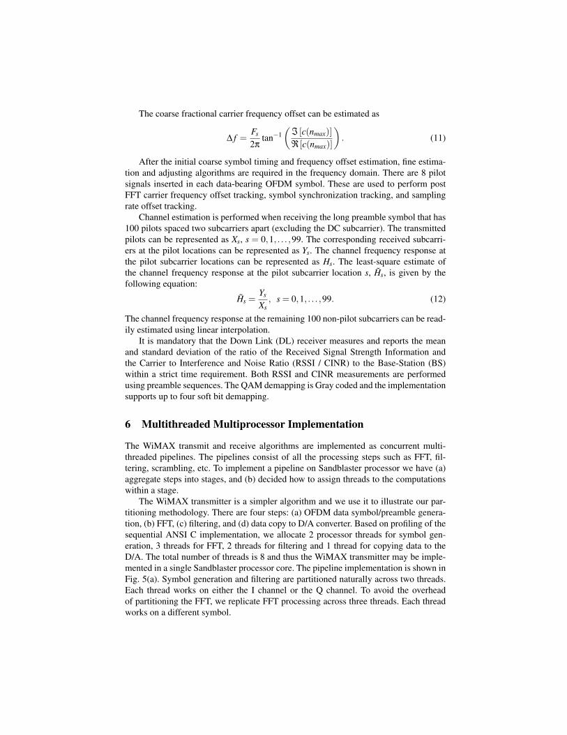
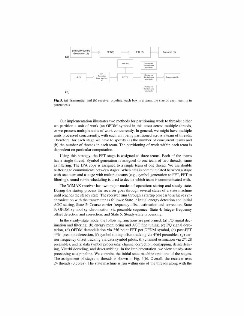
The WiMAX transmitter is a simpler algorithm and we use it to illustrate our par-titioning methodology. There are four steps: (a) OFDM data symbol/preamble genera-tion, (b) FFT, (c) filtering, and (d) data copy to D/A converter. Based on profiling of thesequential ANSI C implementation, we allocate 2 processor threads for symbol gen-eration, 3 threads for FFT, 2 threads for filtering and 1 thread for copying data to theD/A. The total number of threads is 8 and thus the WiMAX transmitter may be imple-mented in a single Sandblaster processor core. The pipeline implementation is shown inFig. 5(a). Symbol generation and filtering are partitioned naturally across two threads.Each thread works on either the I channel or the Q channel. To avoid the overheadof partitioning the FFT, we replicate FFT processing across three threads. Each threadworks on a different symbol.
(a)
Symbol/PreambleGeneration (2) FFT(3) FIR (2) Transmit (1)
(b)
Descrambler (1)I,Q (1)
AGC (1) De mapperDeinterleaver
Viterbi (4)
De mapperDeinterleaver
Viterbi (4)
De mapperDeinterleaver
Viterbi (4)
FIRDerotation
State Machine(4)
FFT (4)
Fig. 5. (a) Transmitter and (b) receiver pipeline; each box is a team, the size of each team is inparenthesis
Our implementation illustrates two methods for partitioning work to threads: eitherwe partition a unit of work (an OFDM symbol in this case) across multiple threads,or we process multiple units of work concurrently. In general, we might have multipleunits processed concurrently, with each unit being partitioned across a team of threads.Therefore, for each stage we have to specify (a) the number of concurrent teams and(b) the number of threads in each team. The partitioning of work within each team isdependent on particular computation.
Using this strategy, the FFT stage is assigned to three teams. Each of the teamshas a single thread. Symbol generation is assigned to one team of two threads, sameas filtering. The D/A copy is assigned to a single team of one thread. We use doublebuffering to communicate between stages. When data is communicated between a stagewith one team and a stage with multiple teams (e.g., symbol generation to FFT, FFT tofiltering), round-robin scheduling is used to decide which team is communicated with.
The WiMAX receiver has two major modes of operation: startup and steady-state.During the startup process the receiver goes through several states of a state machineuntil reaches the steady state. The receiver runs through a startup process to achieve syn-chronization with the transmitter as follows: State 1: Initial energy detection and initialAGC setting, State 2: Coarse carrier frequency offset estimation and correction, State3: OFDM symbol synchronization via preamble sequence, State 4: Integer frequencyoffset detection and correction, and State 5: Steady-state processing.
In the steady-state mode, the following functions are performed: (a) I/Q signal dec-imation and filtering, (b) energy monitoring and AGC fine tuning, (c) I/Q signal dero-tation, (d) OFDM demodulation via 256 point FFT per OFDM symbol, (e) post-FFT4*64 preamble detection, (f) symbol timing offset tracking via 4*64 preambles, (g) car-rier frequency offset tracking via data symbol pilots, (h) channel estimation via 2*128preambles, and (i) data symbol processing: channel correction, demapping, deinterleav-ing, Viterbi decoding, and descrambling. In the implementation, we view steady-stateprocessing as a pipeline. We combine the initial state machine onto one of the stages.The assignment of stages to threads is shown in Fig. 5(b). Overall, the receiver uses24 threads (3 cores). The state machine is run within one of the threads along with the
FIR/derotation team. Depending on the state transition, data is either passed to the FFTstage (in State 5) or to the thread responsible for the four initial states.
The receiver performance for 2.9 Mbps has been tested according to IEEE802.16specifications. The targeted receiver SNR was 3.0 dB when using BPSK modulationwith 1/2-rate convolutional coding. The measured receiver SNR was 1.59 dB whenusing 4-bit soft decoding. The simulation has been performed in the Sandblaster simu-lator. The Sandblaster SB3010 chip is sufficient for a complete ANSI C implementationof the entire physical layer processing. All results have been validated on the hardwaredevelopment board including complete RF and baseband processing.
7 Conclusion
We have presented a real-time implementation of 2.9Mbps WiMAX on the SandblasterSDR platform. Our work demonstrates that a software implementation of WiMAX,suitable for mobile applications can be achieved on the same platform along with othercommunication protocols [10, 11].
References
1. IEEE: IEEE standard for local and metropolitan area networks Part 16: Air interface forfixed broadband wireless access systems. Std. 802.16 (2004)
2. Intersil: Tutorial on basic link budget analysis. App. Note AN9804.1 (1998)3. Miller, L.E.: LinkCalc: NIST link budget calculator. Technical report, National Institute of
Standards and Technology, (Gaithersburg, MA)4. Miller, L.E.: General purpose propagation loss calculator propagation models: CCIR-Hata
Walfisch-Ikegami (WIM). Technical report, Wireless Communication Technologies Group,National Institute of Standards and Technology, (Gaithersburg, MA)
5. Erceg, V., Hari, K.V.S., Smith, M.S., Baum, D.S., Sheikh, K.P., Tappenden, C., Costa, J.M.,Bushue, C., Sarajedini, A., Schwartz, R., Branlund, D., Kaitz, S., Trinkwon, D.: Channelmodels for fixed wireless applications. IEEE 802.16a WG document 802.16.3c-01/29r4,IEEE (2001)
6. Glossner, J., Mougdill, M., Iancu, D., Nacer, G., Jintukar, S., Stanley, S., Samori, M., Raja,T., Schulte, M.: The Sandbridge Sandblaster convergence platform (2005)
7. Nichols, B., Buttlar, D., Proulx-Farrell, J.: Pthreads Programming: A POSIX Standard forBetter Multiprocessing. 1st edn. O’Reilly & Associates, Sebastopol, CA (1996)
8. Kotlyar, V., Moudgill, M.: Detecting overflow detection. In: Proc. IEEE/ACM/IFIP Int. Conf.Hardware/Software Codesign and System Synthesis, Stockholm, Sweden (2004) 36–41
9. Glossner, J., Dorward, S., Jinturkar, S., Moudgill, M., Hokenek, E., Schulte, M., Vassiliadis,S.: Sandbridge software tools. In: Proc. Int. Workshop Systems, Architectures, Modeling,and Simulation, Samos, Greece (2003) 142–148
10. Glossner, J., Iancu, D., Lu, J., Hokenek, E., , Moudgill, M.: Software-defined communica-tions baseband design. IEEE Communications Magazine 41 (2003) 120–128
11. Glossner, J., Iancu, D., Nacer, G., Stanley, S., Hokenek, E., Moudgill, M.: Multiple com-munication protocols for software defined radio. In: Proc. IEE Colloquium on DSP EnableRadio, Livingston, Scotland (2003) 227–236
Related Documents