Software Engineering UNIT 2. Functional Modelling

Software Engineering UNIT 2. Functional Modelling.
Dec 25, 2015
Welcome message from author
This document is posted to help you gain knowledge. Please leave a comment to let me know what you think about it! Share it to your friends and learn new things together.
Transcript

Software Engineering
UNIT 2. Functional Modelling
Objectives Actors Identification Static Context Diagrams Use Cases Identification Use Case Diagrams Development Use Case Textual Description Graphically Use Case Description Activity Diagrams Development Sequence Diagrams Development Use Case Make-up (Inclusion / Extension /
Generalisation ) Use Case Make-Up in packages
1. How to identify all the actors ? Actor Features A human user or a system who send or receive
one or more messages; the message must contains an important or representative information.
Example: a student for a school library Non-Example : a Credit Card for a supermarket
or an ATM To identify the human user must to search all
the person who have a realtion with the aplication without forget the system administrator, analyst – programmer , etc.
Actor features An extern entity This entity has a relation with the aplicattion A human being,extern object,other system Actor=a answer for the next question Who use the aplication ? Who install, start, stop or keep the aplication
? Who send or receive information for the
aplication ? Which other system use or donne services
to aplication ?
How to represent an actor ?
The Stick Man Model
Principal / Second actor
2.The Static Context Diagram The Static Context Diagram contains all
the actors off the application Each actor in this diagram has
associated his multiplicity The human actor it is represent with a
stick man A system-actor it is represent with a
rectangle and in the rectangle-center it is the name of this actor
Example of Static Context Diagram
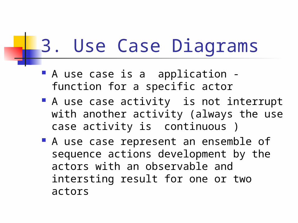
3. Use Case Diagrams A use case is a application - function for
a specific actor A use case activity is not interrupt with
another activity (always the use case activity is continuous )
A use case represent an ensemble of sequence actions development by the actors with an observable and intersting result for one or two actors
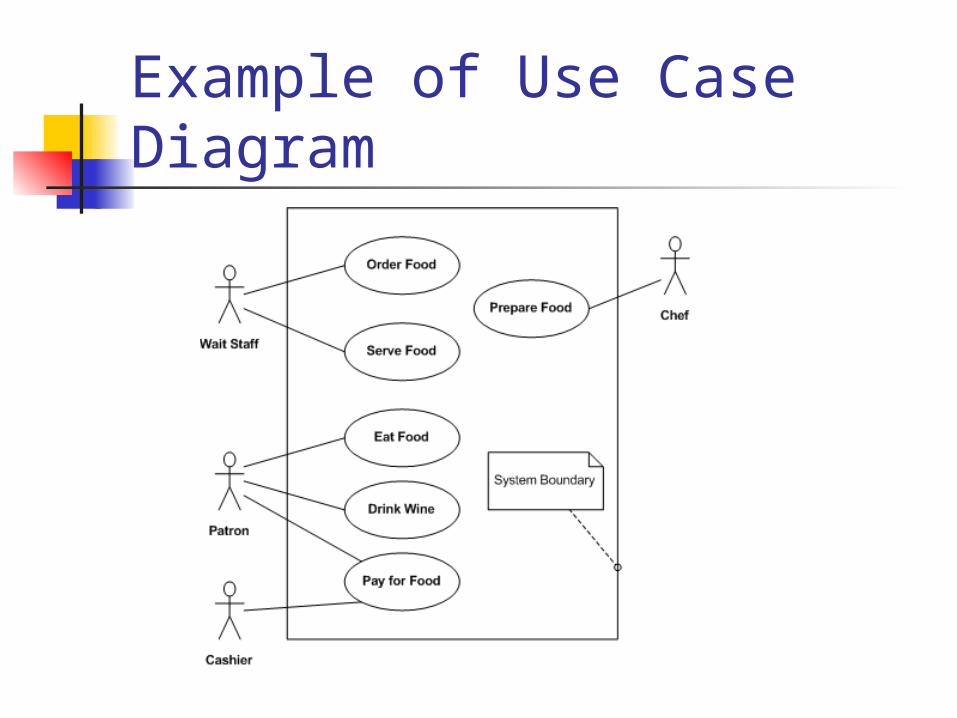
Example of Use Case Diagram
Actors & Use Case For the next use case it is necessary the two
actors The use case it isn’t work without the two
actors
Include Relationship In one form of interaction, a given use case may
include another The first use case often depends on the outcome of
the included use case. This is useful for extracting truly common behaviors
from several use cases into a single description This usage resembles a macro expansion where the
included use case behavior is placed inline in the base use case behavior
The notation is a dashed arrow from the including to the included use case, with the label «include».
The Source Use Case contain/ involve the behavior described by the including use case
Example of Include Relationship
Extend Relationship This relationship indicates that the
behavior of the extension use case may be inserted in the extended use case under some conditions
This can be useful for dealing with special cases, or in accommodating new requirements during system maintenance and extension.
The notation is a dashed arrow from the extension to the extended use case, with the label «extend»
Condition to satisfy for using the extend relation !
Example of Extend Relationship
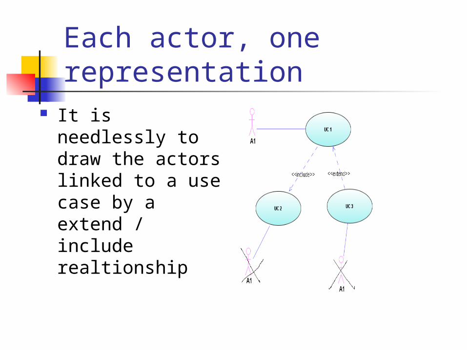
Each actor, one representation
It is needlessly to draw the actors linked to a use case by a extend / include realtionship
A generalization/specialization relationship
Explanation A given use case may be a specialized form of
an existing use case This resembles the object-oriented concept of
sub-classing, in practice it can be both useful and effective to factor common behaviors, constraints and assumptions to the general use case, describe them once, and deal with same as except details in the specialized cases
This relationship is used to define a more specific function / use case for one informations traitement
Inheritance of behavior,features and relationship
Use Case Description An use case must remain simple An use case is a indivisble « movie » A representative name for each use
case ( a verb ) Don’t give a very exactly name for a
use case Example : introduce the client first name,introduce the
client age,etc Don’t modelling out the application Minimum 1 actor for an use case
Use case fragmentation If the interactions are very
complexes If there are independents use case Each fragment of an use case must
have minimum 1 actor
4.How to develop the use case diagram Identify the actors ( main actors,
secondary actors, systems-actors ) Identify the use cases for each actor Design the primary diagram Identify the generalisation relationship
between the actors Main actors at left, secondary at right Fragment all complex use cases (include,
extend , specialisation relationship )
Example
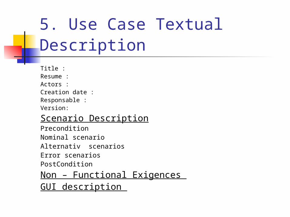
5. Use Case Textual Description Title : Resume :Actors : Creation date : Responsable : Version:
Scenario Description Precondition Nominal scenario Alternativ scenariosError scenariosPostCondition
Non – Functional Exigences GUI description
6. Graphically Use Case Description All the use cases must be documented A documenation for a use case must
contain a sequence diagram and/or activity diagram
The nominal scenario must have a textual description and also a sequence/activity diagram
Only for the very important use cases it is necessary the sequence and activity diagrams
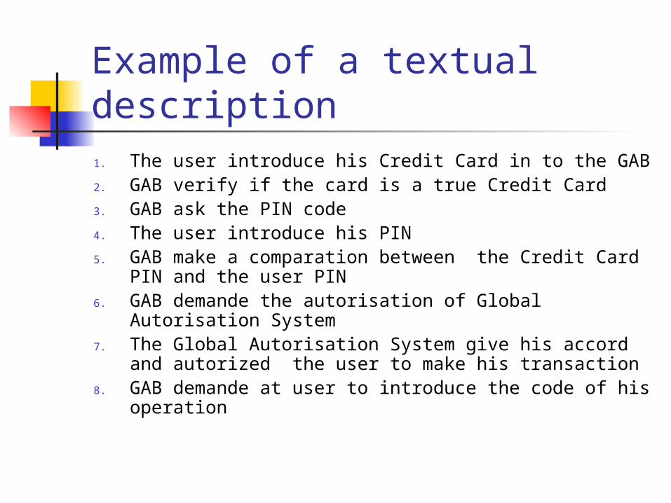
Example of a textual description1. The user introduce his Credit Card in to the GAB 2. GAB verify if the card is a true Credit Card 3. GAB ask the PIN code 4. The user introduce his PIN5. GAB make a comparation between the Credit
Card PIN and the user PIN 6. GAB demande the autorisation of Global
Autorisation System7. The Global Autorisation System give his accord
and autorized the user to make his transaction8. GAB demande at user to introduce the code of his
operation
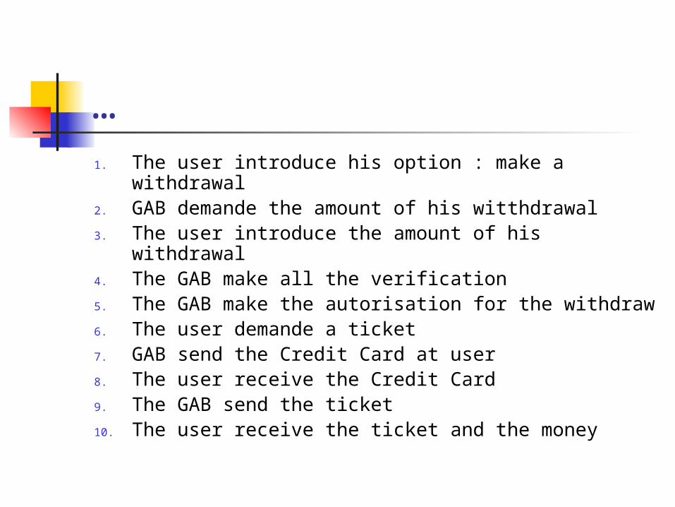
…1. The user introduce his option : make a withdrawal 2. GAB demande the amount of his witthdrawal3. The user introduce the amount of his withdrawal 4. The GAB make all the verification5. The GAB make the autorisation for the withdraw6. The user demande a ticket 7. GAB send the Credit Card at user8. The user receive the Credit Card9. The GAB send the ticket10. The user receive the ticket and the money
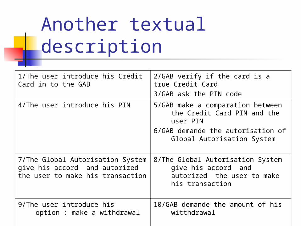
Another textual description
1/The user introduce his Credit Card in to the GAB
2/GAB verify if the card is a true Credit Card3/GAB ask the PIN code
4/The user introduce his PIN 5/GAB make a comparation between the Credit Card PIN and the user PIN
6/GAB demande the autorisation of Global Autorisation System
7/The Global Autorisation System give his accord and autorized the user to make his transaction
8/The Global Autorisation System give his accord and autorized the user to make his transaction
9/The user introduce his option : make a withdrawal
10/GAB demande the amount of his witthdrawal
…. ….
7.Sequence diagram
Example
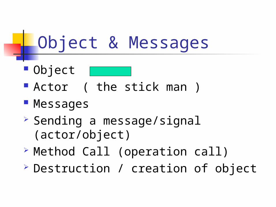
Object & Messages Object Actor ( the stick man ) Messages Sending a message/signal
(actor/object) Method Call (operation call) Destruction / creation of object
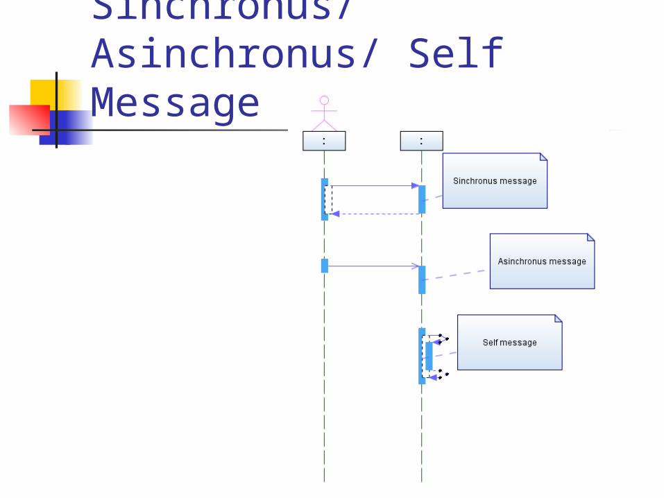
Sinchronus/Asinchronus/ Self Message
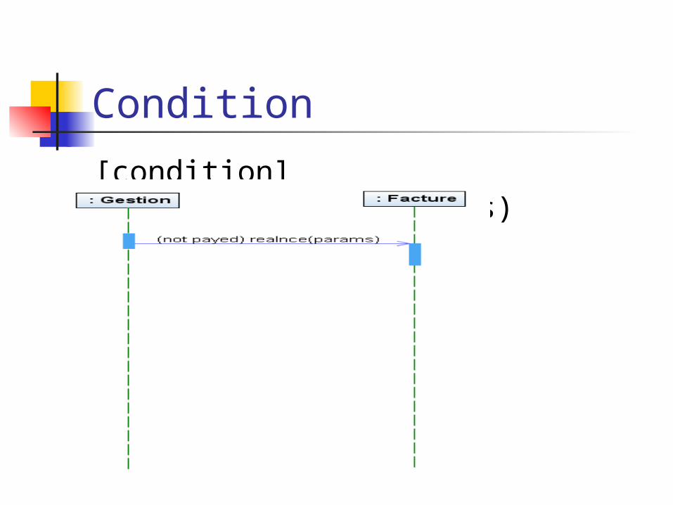
Condition
[condition] results:=message(args)
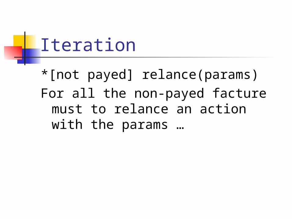
Iteration
*[not payed] relance(params) For all the non-payed facture must
to relance an action with the params …
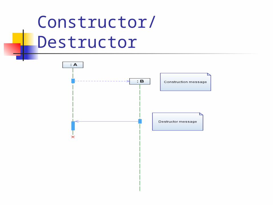
Constructor/ Destructor
Related Documents