1 © 2006 Bernd Bruegge Software Engineering WS 2006/2007 Software Lifecycles Models Bernd Bruegge Applied Software Engineering Technische Universitaet Muenchen Software Engineering Lecture 17

Welcome message from author
This document is posted to help you gain knowledge. Please leave a comment to let me know what you think about it! Share it to your friends and learn new things together.
Transcript

1© 2006 Bernd Bruegge Software Engineering WS 2006/2007
Software Lifecycles Models
Bernd BrueggeApplied Software Engineering
Technische Universitaet Muenchen
Software Engineering Lecture 17

2© 2006 Bernd Bruegge Software Engineering WS 2006/2007
Outline of Today’s Lecture
• Modeling the software life cycle• Sequential models
• Pure waterfall model• V-model• Sawtooth model
• Iterative models• Boehm’s spiral model• Unified Process
• Entity-oriented models• Issue-based model

3© 2006 Bernd Bruegge Software Engineering WS 2006/2007
Typical Software Life Cycle Questions
• Which activities should we select for the software project?• What are the dependencies between activities?• How should we schedule the activities?• To find these activities and dependencies we can use the same modeling
techniques we use for software development:• Functional Modeling of a Software Lifecycle
• Scenarios• Use case model
• Structural modeling of a Software Lifecycle• Object identification• Class diagrams
• Dynamic Modeling of a Software Lifecycle• Sequence diagrams, statechart and activity diagrams

4© 2006 Bernd Bruegge Software Engineering WS 2006/2007
Definitions
• Software life cycle:• Set of activities and their relationships to each other to
support the development of a software system
• Software development methodology:• A collection of techniques for building models applied
across the software life cycle

5© 2006 Bernd Bruegge Software Engineering WS 2006/2007
DeveloperClient Project manager
System developmentProblem definition
<<include>><<include>>
<<include>>
Software development
System operation
End userAdministrator
Functional Model of a simple life cyclemodel

6© 2006 Bernd Bruegge Software Engineering WS 2006/2007
Systemoperationactivity
Systemdevelopmentactivity
Problemdefinitionactivity
Software development goes through a linear progression of statescalled software development activities
Activity Diagram for the same Life CycleModel
7© 2006 Bernd Bruegge Software Engineering WS 2006/2007
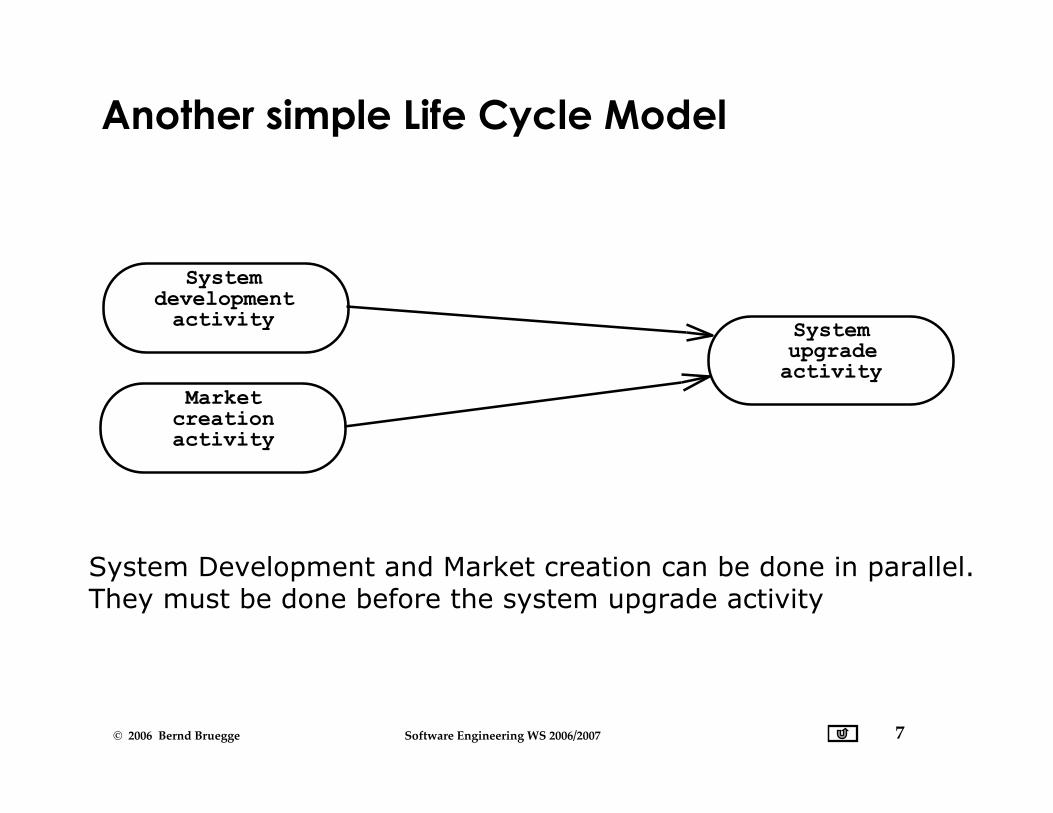
Another simple Life Cycle Model
System Development and Market creation can be done in parallel.They must be done before the system upgrade activity
Systemupgradeactivity
Marketcreationactivity
Systemdevelopmentactivity

8© 2006 Bernd Bruegge Software Engineering WS 2006/2007
Two Major Views of the Software Life Cycle
• Activity-oriented view of a software life cycle• Software development consists of a set of development
activities
• all the examples so far
• Entity-oriented view of a software life cycle• Software development consists of the creation of a set of
deliverables.

9© 2006 Bernd Bruegge Software Engineering WS 2006/2007
Entity-centered view of Software Development
Lessons learneddocument
System specificationdocument Executable system
Market surveydocument
Software Development
Software development consists of the creation of a set of deliverables
10© 2006 Bernd Bruegge Software Engineering WS 2006/2007
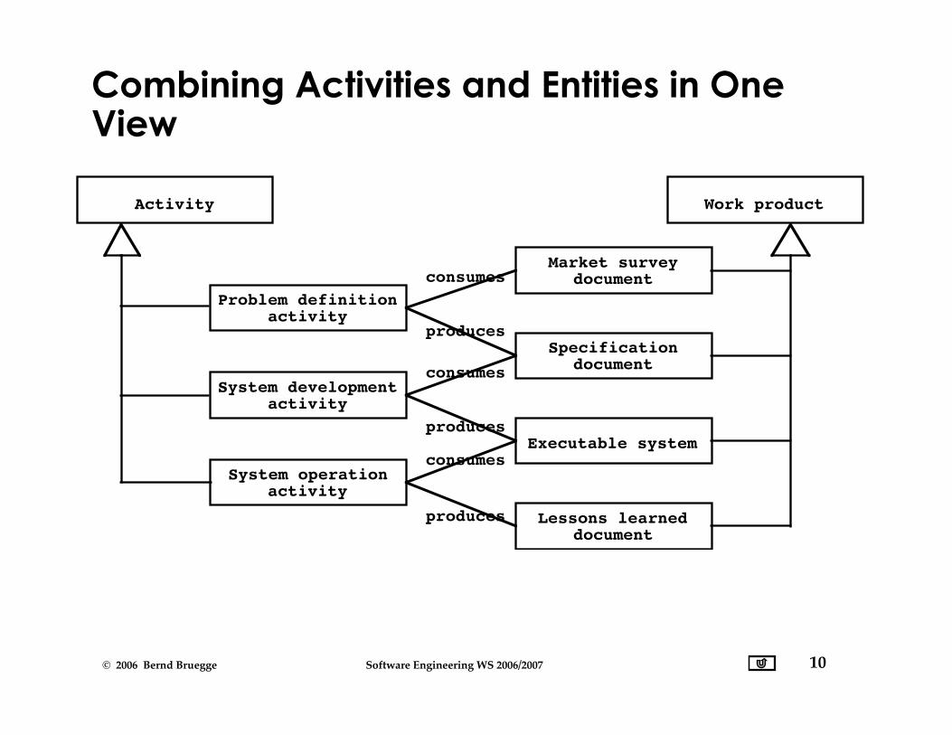
Specification
Executable system
Lessons learned
Market survey
Problem definition
System development
System operation
Activity Work product
consumes
produces
consumes
produces
consumes
produces
activity
activity
activity
document
document
document
Combining Activities and Entities in OneView

11© 2006 Bernd Bruegge Software Engineering WS 2006/2007
IEEE Std 1074: Standard for Software LifeCycle Activities
IEEE Std 1074
Project Management
Pre-Development
Develop-ment
Post-Development
Cross-Development
(Integral Processes)
> Project Initiation>Project Monitoring &Control> Software Quality Management
> Concept Exploration> System Allocation
> Requirements> Design> Implemen- tation
> Installation> Operation & Support> Maintenance> Retirement
> V & V> Configuration Management> Documen- tation> Training
Process Group
Process

12© 2006 Bernd Bruegge Software Engineering WS 2006/2007
Object Model of the IEEE 1074 Standard
Process Group
Activity Work Product
Resource
Task
Process
Money
Time
Participant
consumed by
produces
Work Unit
*
*
*
*
Software Life Cycle
*
*
13© 2006 Bernd Bruegge Software Engineering WS 2006/2007
Life Cycle Modeling
• Many models have been proposed to deal withthe problems of defining activities andassociating them with each other
• The first model proposed was the waterfall model[Royce]
• Spiral model [Boehm]• Objectory process [Jacobsen]• Rational process [Kruchten]• Unified process [Jacobsen, Booch, Rumbaugh]

14© 2006 Bernd Bruegge Software Engineering WS 2006/2007
RequirementsProcess
SystemAllocationProcess
ConceptExplorationProcess
DesignProcess
ImplementationProcess
InstallationProcess
Operation &Support Process
Verification& Validation
Process
The Waterfall Model ofthe Software LifeCycle
adapted from [Royce 1970]

15© 2006 Bernd Bruegge Software Engineering WS 2006/2007
DOD Standard 2167A
• Example of a waterfall model with the followingsoftware development activities
• System Requirements Analysis/Design• Software Requirements Analysis• Preliminary Design and Detailed Design• Coding and CSU testing• CSC Integration and Testing• CSCI Testing• System integration and Testing
• Required by the U.S. Department of Defense forall software contractors in the 1980-90’s.

16© 2006 Bernd Bruegge Software Engineering WS 2006/2007
Activity Diagram ofMIL DOD-STD-2167A
PreliminaryDesign Review
Critical DesignReview (CDR)
SystemRequirements
Review
SystemDesignReview
SoftwareSpecification
Review
SystemRequirementsAnalysis
SoftwareRequirementsAnalysis
SystemDesign
…
PreliminaryDesign
DetailedDesign
Coding &CSU Testing
CSCIntegration& Testing

17© 2006 Bernd Bruegge Software Engineering WS 2006/2007
From the Waterfall Model to the V Model
System Design
RequirementsAnalysis
RequirementsEngineering
ObjectDesign
IntegrationTesting
SystemTesting
Unit Testing
Implemen-tation
SystemTesting
Unit Testing
Integration Testing
Acceptance
18© 2006 Bernd Bruegge Software Engineering WS 2006/2007
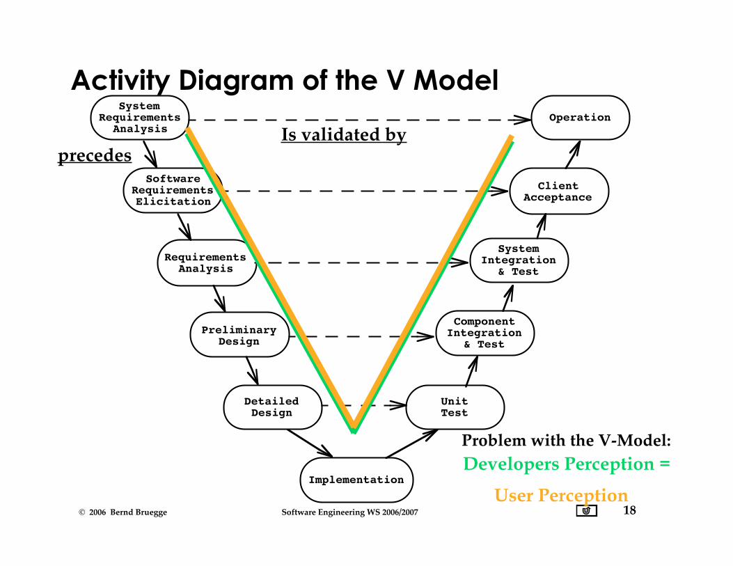
Activity Diagram of the V ModelSystem
RequirementsAnalysis
Implementation
PreliminaryDesign
DetailedDesign
SoftwareRequirementsElicitation
Operation
ClientAcceptance
RequirementsAnalysis
UnitTest
SystemIntegration
& Test
ComponentIntegration
& Test
Problem with the V-Model: Developers Perception =
User Perception
precedesIs validated by

19© 2006 Bernd Bruegge Software Engineering WS 2006/2007
Properties of Waterfall-based Models
• Managers love waterfall models• Nice milestones• No need to look back (linear system)• Always one activity at a time• Easy to check progress during development: 90%
coded, 20% tested
• However, software development is non-linear• While a design is being developed, problems with
requirements are identified• While a program is being coded, design and
requirement problems are found• While a program is tested, coding errors, design errors
and requirement errors are found.
20© 2006 Bernd Bruegge Software Engineering WS 2006/2007
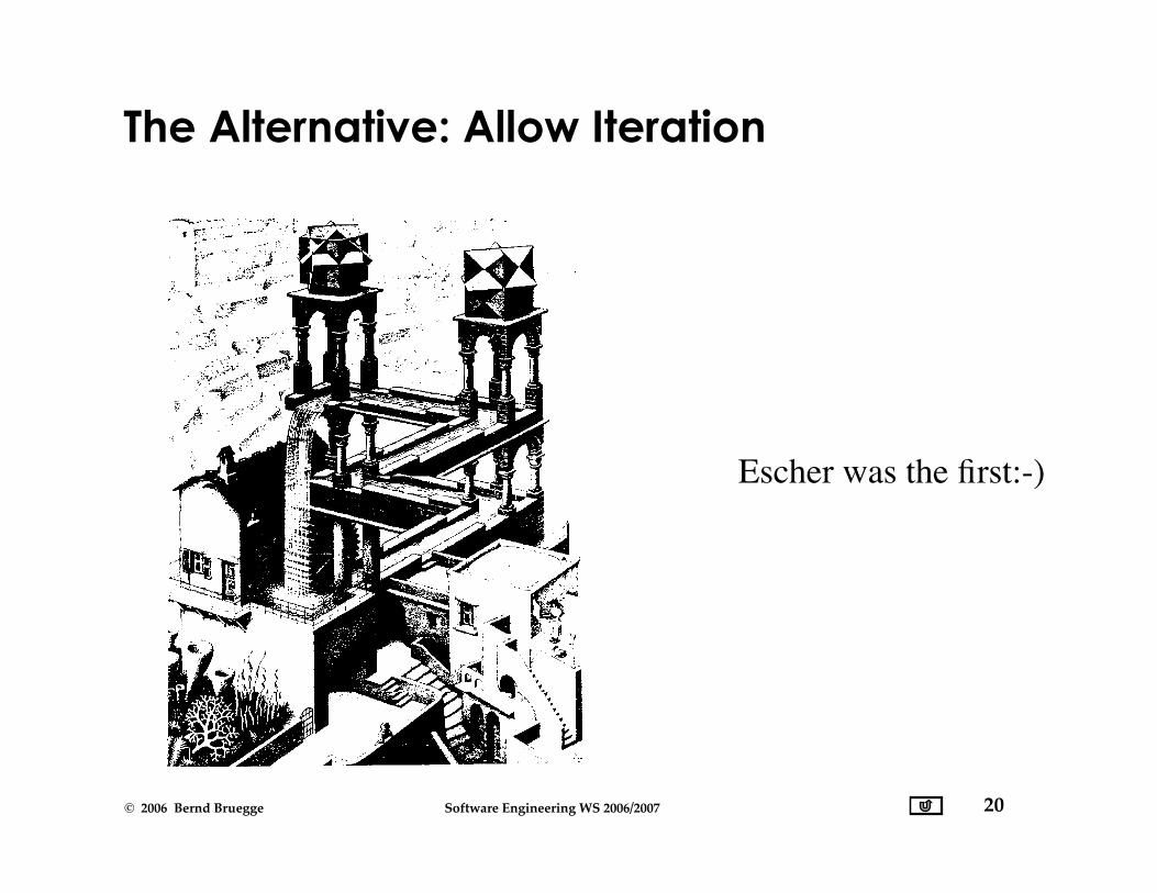
Escher was the first:-)
The Alternative: Allow Iteration
21© 2006 Bernd Bruegge Software Engineering WS 2006/2007
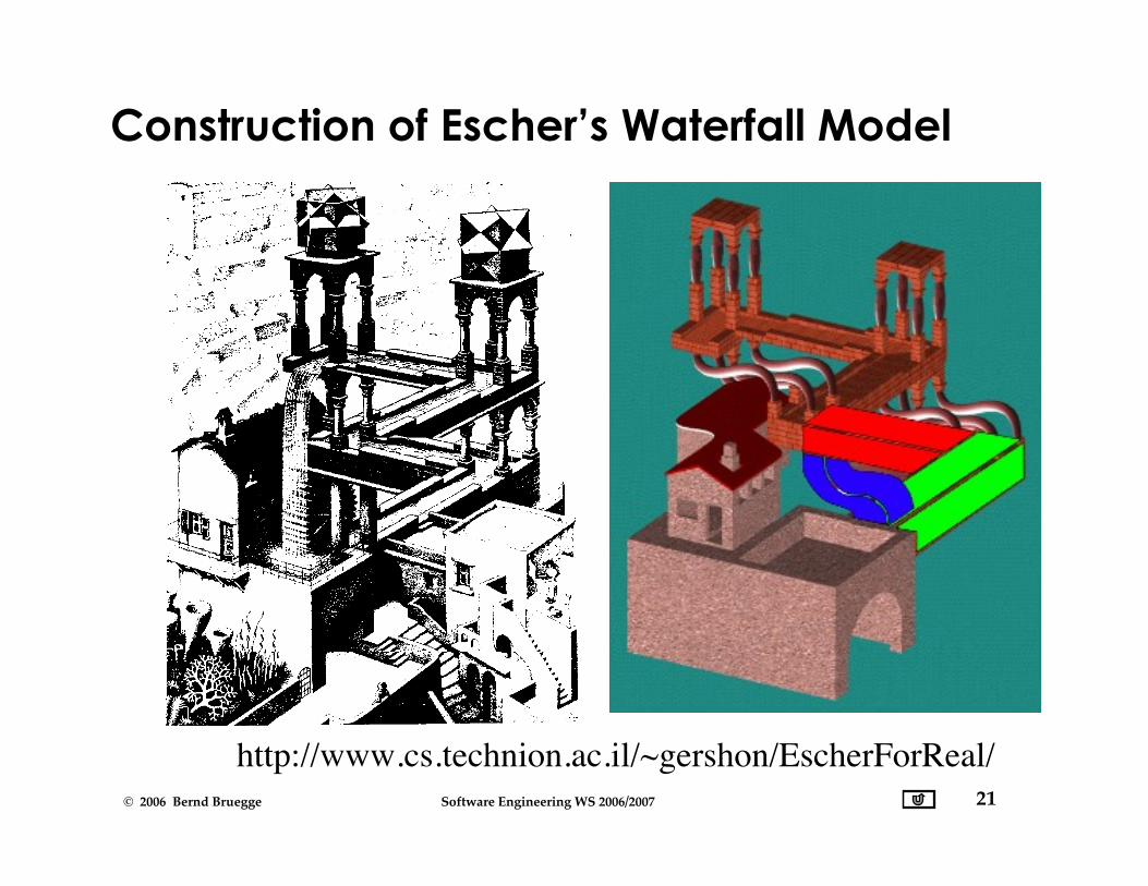
Construction of Escher’s Waterfall Model
http://www.cs.technion.ac.il/~gershon/EscherForReal/
22© 2006 Bernd Bruegge Software Engineering WS 2006/2007
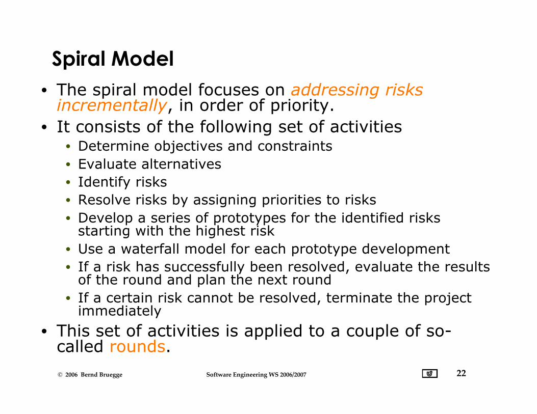
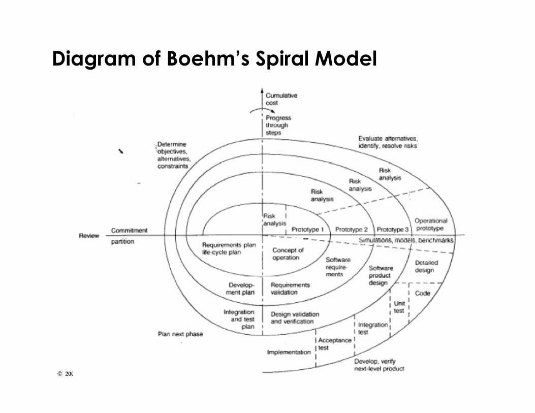
• The spiral model focuses on addressing risksincrementally, in order of priority.
• It consists of the following set of activities• Determine objectives and constraints• Evaluate alternatives• Identify risks• Resolve risks by assigning priorities to risks• Develop a series of prototypes for the identified risks
starting with the highest risk• Use a waterfall model for each prototype development• If a risk has successfully been resolved, evaluate the results
of the round and plan the next round• If a certain risk cannot be resolved, terminate the project
immediately
• This set of activities is applied to a couple of so-called rounds.
Spiral Model

23© 2006 Bernd Bruegge Software Engineering WS 2006/2007
Rounds in Boehm’s Spiral Model
• Concept of Operations• Software
Requirements• Software Product
Design• Detailed Design• Code• Unit Test• Integration and Test• Acceptance Test• Implementation
• For each round gothrough these activities:
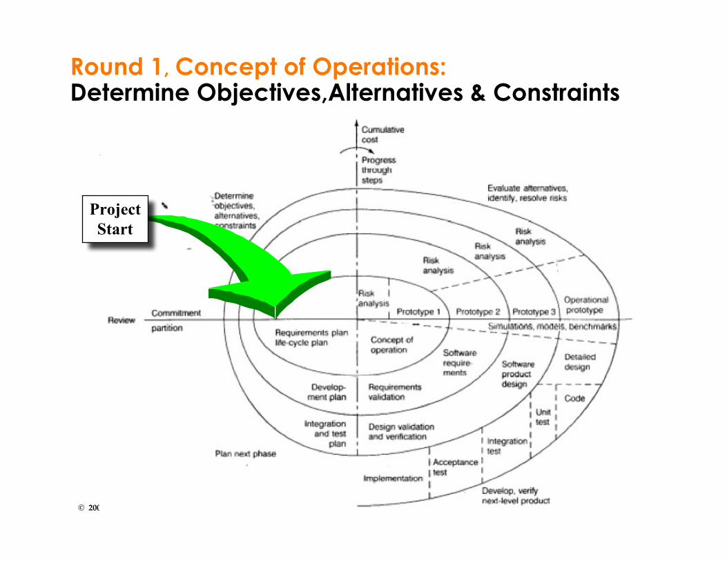
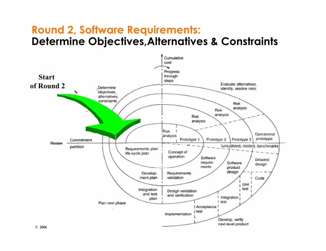
• Define objectives,alternatives,constraints
• Evaluate alternatives,identify and resolverisks
• Develop and verify aprototype
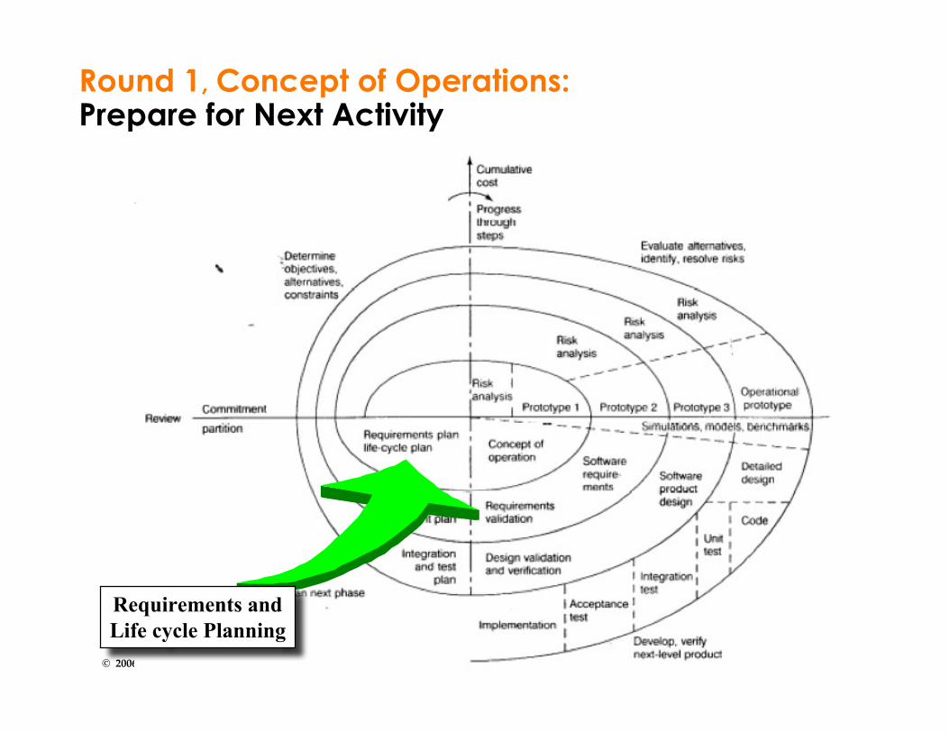
• Plan the next round.
Disccourse on Prototyping
24© 2006 Bernd Bruegge Software Engineering WS 2006/2007
Diagram of Boehm’s Spiral Model
25© 2006 Bernd Bruegge Software Engineering WS 2006/2007
Round 1, Concept of Operations:Determine Objectives,Alternatives & Constraints
ProjectStart

26© 2006 Bernd Bruegge Software Engineering WS 2006/2007
Round 1, Concept of Operations:Evaluate Alternatives, identify & resolve Risks
Risk Analysis

27© 2006 Bernd Bruegge Software Engineering WS 2006/2007
Round 1, Concept of Operations:Develop and Verify
Concept of Operation Activity
28© 2006 Bernd Bruegge Software Engineering WS 2006/2007
Round 1, Concept of Operations:Prepare for Next Activity
Requirements andLife cycle Planning
29© 2006 Bernd Bruegge Software Engineering WS 2006/2007
Round 2, Software Requirements:Determine Objectives,Alternatives & Constraints
Start of Round 2

30© 2006 Bernd Bruegge Software Engineering WS 2006/2007
Comparison of ProjectsDetermine objectives,alternatives, & constraints
Evaluate alternatives,identify & resolve risks
Develop & verifynext level productPlan next phase
Requirements
Development
Integration
plan
plan
plan
Requirements
Design
validation
validation
SoftwareSystem
Product
Riskanalysis
Riskanalysis
Prototype1
Prototype2
Prototype3
Riskanalysis
Concept ofoperation
Requirements
Design
Code
Unit Test
Integration & Test
Acceptance
DetailedDesign
P1
P2
Test
Project P1
Project P2

31© 2006 Bernd Bruegge Software Engineering WS 2006/2007
Outline of Today’s Lecture
Modeling the software life cycleSequential models
Pure waterfall modelV-modelSawtooth model
Iterative modelsBoehm’s spiral model• Unified Process
• Entity-oriented models• Issue-based model

32© 2006 Bernd Bruegge Software Engineering WS 2006/2007
Unified Process
• The Unified Process is another iterative processmodel
• States of a software system developed with theUnified Process
• Inception, Elaboration, Construction, Transition
• Artifacts Sets• Management Set, Engineering Set
• Workflows• Management, Environment, Requirements, Design,
Implementation, Assessment, Deployment
• Iterations are managed as software projects• Project participants are called stakeholders.
33© 2006 Bernd Bruegge Software Engineering WS 2006/2007
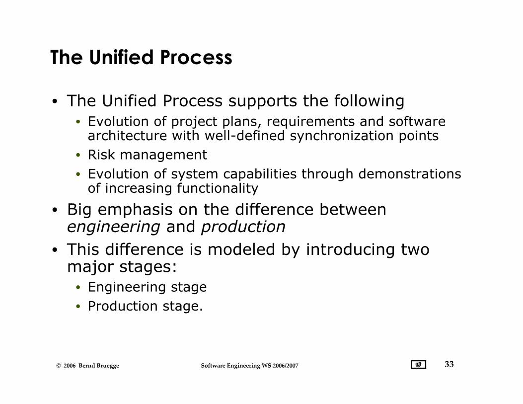
The Unified Process
• The Unified Process supports the following• Evolution of project plans, requirements and software
architecture with well-defined synchronization points• Risk management• Evolution of system capabilities through demonstrations
of increasing functionality
• Big emphasis on the difference betweenengineering and production
• This difference is modeled by introducing twomajor stages:
• Engineering stage• Production stage.

34© 2006 Bernd Bruegge Software Engineering WS 2006/2007
Difference: Engineering vs. Production
• Engineering Stage:• Focuses on analysis and design activities, driven by
unpredictable teams
• Production Stage:• Focuses on construction, test and deployment, driven by
more predictable but larger teams
Focus FactorRisk
Activities
Artifacts
Quality Assessment
Engineering StageSchedule, technical feasibility
Planning, Analysis, Design
Requirement Analysis andSystem Design DocumentsDemonstration, Inspection
Production StageCost
Implementation, Integration
Baselines, Releases
Testing
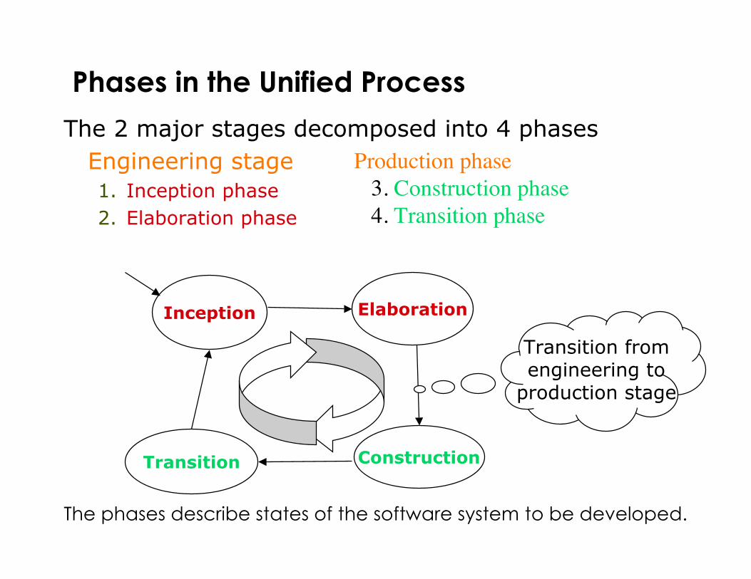
Phases in the Unified Process
The 2 major stages decomposed into 4 phases Engineering stage
1. Inception phase2. Elaboration phase
ElaborationInception
ConstructionTransition
Transition from engineering to production stage
Production phase3. Construction phase4. Transition phase
The phases describe states of the software system to be developed.
36© 2006 Bernd Bruegge Software Engineering WS 2006/2007
Inception Phase: Objectives
• Establish the project’s scope• Define acceptance criteria• Identify the critical use cases and scenarios• Demonstrate at least one candidate software
architecture• Estimate the cost and schedule for the project• Define and estimate potential risks

37© 2006 Bernd Bruegge Software Engineering WS 2006/2007
Elaboration Phase: Objectives
At the end of this phase, the “engineering” of thesystem is complete
A decision must be made:• Commit to production phase?• Move to an operation with higher cost risk and inertia
(i.e. bureaucracy)
Main questions:• Are the system models and project plans stable
enough?• Have the risks been dealt with?• Can we predict cost and schedule for the completion of
the development for an acceptable range?

38© 2006 Bernd Bruegge Software Engineering WS 2006/2007
Construction Phase: Objectives
• Minimize development costs by optimizingresources
• Avoid unnecessary restarts (modeling, coding)
• Achieve adequate quality as fast as possible• Achieve useful version
• Alpha, beta, and other test releases
39© 2006 Bernd Bruegge Software Engineering WS 2006/2007
Transition Phase
• The transition phase is entered• when a baseline is mature enough that it can be
deployed to the user community
• For some projects the transition phase is• the starting point for the next version
• For other projects the transition phase is• a complete delivery to a third party responsible for
operation, maintenance and enhancement of thesoftware system.
40© 2006 Bernd Bruegge Software Engineering WS 2006/2007
Transition Phase: Objectives
• Achieve independence of users• Produce a deployment version is complete and
consistent• Build a release as rapidly and cost-effectively as
possible.

41© 2006 Bernd Bruegge Software Engineering WS 2006/2007
Iteration in the Unified Process
• Each of the four phases introduced so far(inception, elaboration, construction, transition)consists of one or more iterations
• An iteration represents a set of activities forwhich
• have a milestone (“a well-defined intermediate event”)• the scope and results are captured with work-products
called artifacts.
42© 2006 Bernd Bruegge Software Engineering WS 2006/2007
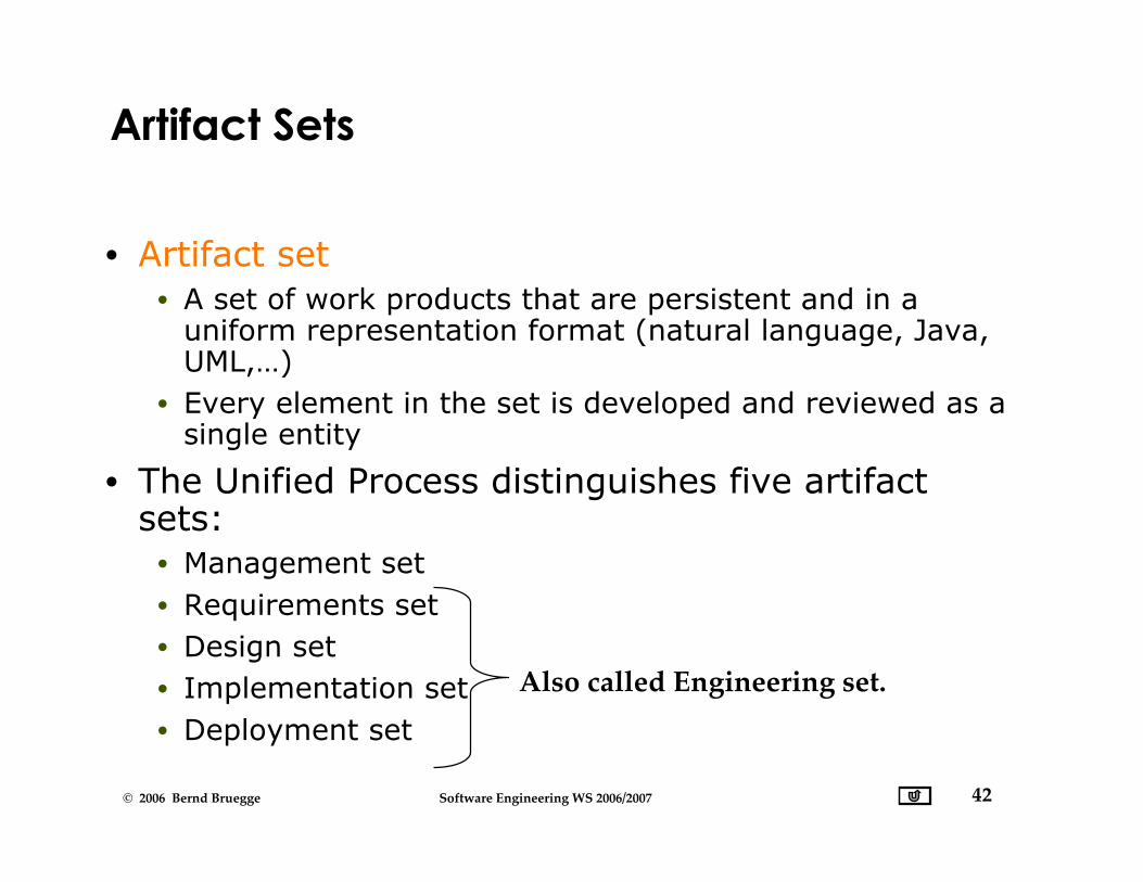
Artifact Sets
• Artifact set• A set of work products that are persistent and in a
uniform representation format (natural language, Java,UML,…)
• Every element in the set is developed and reviewed as asingle entity
• The Unified Process distinguishes five artifactsets:
• Management set• Requirements set• Design set• Implementation set• Deployment set
Also called Engineering set.

Artifact Sets in the Unified Process
RequirementsSet
1. Visiondocument(“problemstatement”)
2. Requirementsmodel(s)
Design Set
1. Design model(s)2. Test model
3. Software architecture
ImplementationSet
1. Source code baselines2. Compile-time files3. Component executables
DeploymentSet
1. Integrated pro- duct executable2. Run-time files
3. User documentation
Management Set
Planning Artifacts1. Work breakdown structure2. Business Case3. Release specifications4. Software ProjectManagement Plan
Operational Artifacts1. Release descriptions2. Status assessments3. Software change orderdatabase4. Deployment documents5. Environment
44© 2006 Bernd Bruegge Software Engineering WS 2006/2007
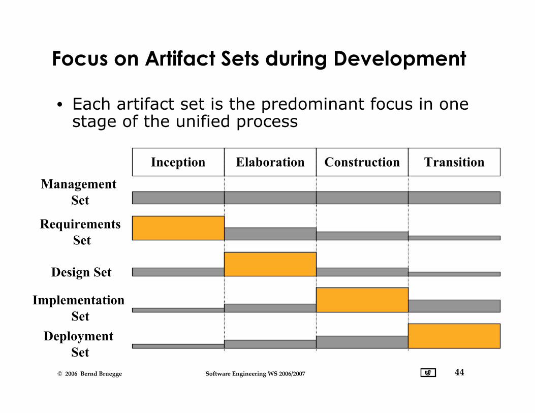
Focus on Artifact Sets during Development
• Each artifact set is the predominant focus in onestage of the unified process
Inception Elaboration Construction TransitionManagement
Set
Requirements Set
Design Set
Implementation Set
Deployment Set
45© 2006 Bernd Bruegge Software Engineering WS 2006/2007
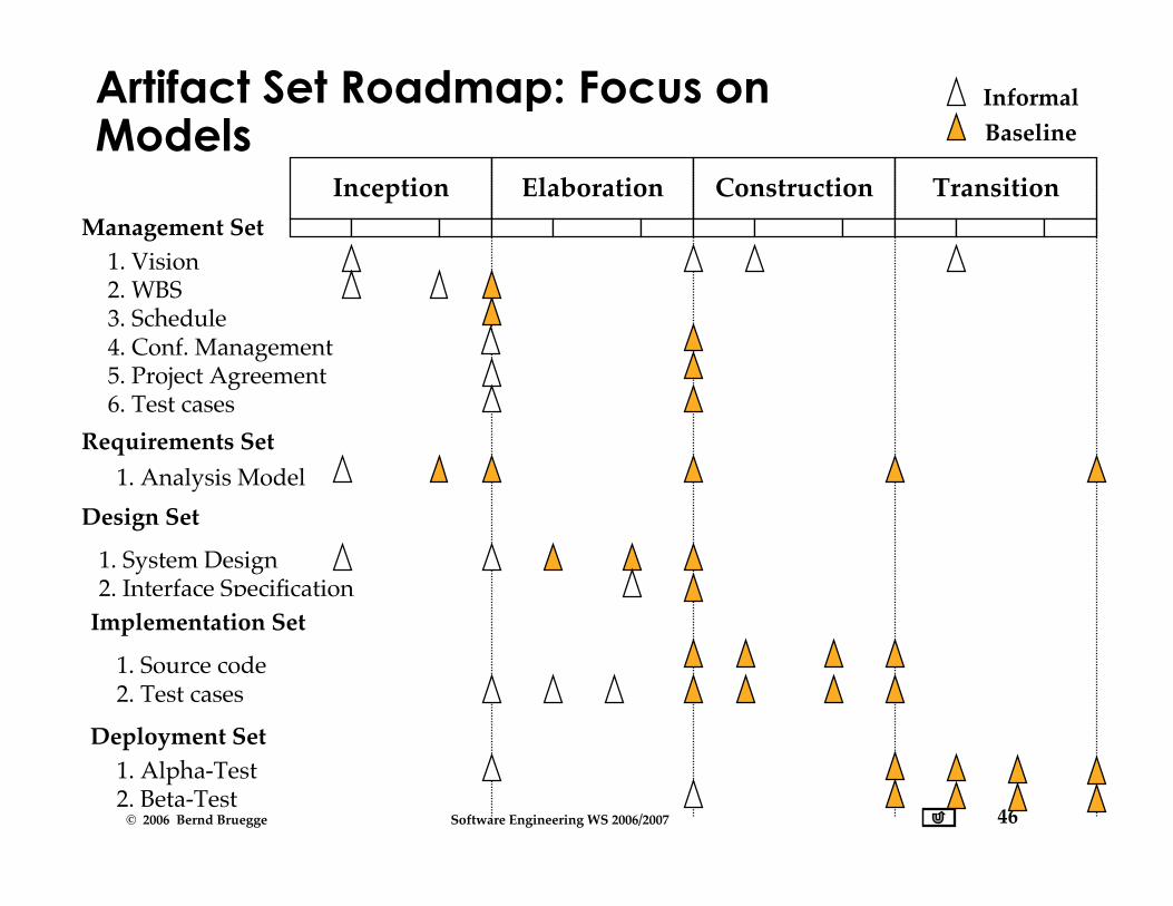
Management of Artifact Sets
• Some artifacts are changed only after a phase• Other artifacts are updated after each minor
milestone, i.e. after an iteration• The project manager is responsible
• to manage and visualize the sequence of artifactsacross the software lifecycle activities
• This visualization is often called artifact roadmap.
46© 2006 Bernd Bruegge Software Engineering WS 2006/2007
Artifact Set Roadmap: Focus onModels
Inception Elaboration Construction TransitionManagement Set
Requirements Set
Design Set
Deployment Set
1. Vision2. WBS3. Schedule4. Conf. Management5. Project Agreement6. Test cases
1. Analysis Model
1. System Design2. Interface Specification
Implementation Set
1. Source code2. Test cases
1. Alpha-Test2. Beta-Test
InformalBaseline

47© 2006 Bernd Bruegge Software Engineering WS 2006/2007
Artifact Set Roadmap: Focus onDocuments
Inception Elaboration Construction TransitionManagement Set
Requirements Set
Design Set
Deployment Set
1. Problem Statement2. WBS3. SPMP4. SCMP5. Project Agreement6. Test plan
1. RAD
1. SDD2. ODD
Implementation Set
1. Source code2. Test cases
1. User Manual2. Administrator Manual
InformalBaseline

48© 2006 Bernd Bruegge Software Engineering WS 2006/2007
Models vs. Documents
• Documentation-driven approach• The production of the documents drives the milestones
and deadlines
• Model-driven approach• The production of the models drive the milestones
deadlines
• Main goal of a modern software developmentproject
• Creation of models and construction of the softwaresystem
• The purpose of documentation is to support this goal.

49© 2006 Bernd Bruegge Software Engineering WS 2006/2007
Reasons for Documentation-Driven Approach
• No rigorous engineering methods and languagesavailable for analysis and design models
• Language for implementation and deployment istoo cryptic
• Software project progress needs to be assessed• Documents represent a mechanism for demonstrating
progress
• People want to review information• but do not understand the language of the artifact
• People wanted to review information,• but do not have access to the tools to view the
information.
50© 2006 Bernd Bruegge Software Engineering WS 2006/2007
Artifact-Driven Approach
• Provides templates for documents at the start ofthe project
• Instantiates documents automatically fromthese templates
• Enriches them with modeling and artifact informationgenerated during the project
• Tools automatically generate documents fromthe models. Examples:
• Schedule generator• Automatic requirements document generator• Automatic interface specification generator• Automatic analysis and design documents generator• Automatic test case generator.
51© 2006 Bernd Bruegge Software Engineering WS 2006/2007
“Process” is an overloaded term
• The Unified Process distinguishes between macroand micro process:
• The macro process models the software lifecycle• The micro process models activities that produce artifacts
• Another meaning for process:• Business process
• The policies, procedures and practices in anorganization pursuing a software-intensive line ofbusiness.
• Focus: Organizational improvement, long-termstrategies, and return on investment (ROI)
• The micro processes are called workflows in theUnified Process.
52© 2006 Bernd Bruegge Software Engineering WS 2006/2007
Workflows in the Unified Process (1)
• Management workflow• Planning the project (Problem statement, SPMP, SCMP,
Test plan)
• Environment workflow• Automation of process and maintenance environment.
Setup of infrastructure (Communication, Configurationmanagement, ...).
• Requirements workflow• Analysis of application domain and creation of
requirements artifacts (analysis model).
• Design workflow• Creation of solution and design artifacts (system
design model, object design model).

53© 2006 Bernd Bruegge Software Engineering WS 2006/2007
Workflows in the Unified Process (2)
• Implementation workflow• Implementation of solution, source code testing,
maintenance of implementation and deploymentartifacts (source code).
• Assessment workflow• Assess process and products (reviews, walkthroughs,
inspections, testing…)
• Deployment workflow• Transition the software system to the end user
54© 2006 Bernd Bruegge Software Engineering WS 2006/2007
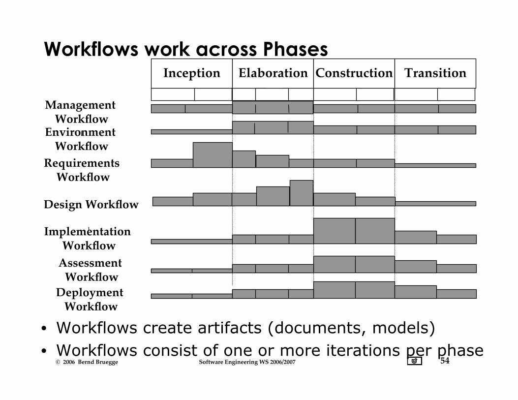
Workflows work across Phases
• Workflows create artifacts (documents, models)• Workflows consist of one or more iterations per phase
Inception Elaboration Construction Transition
Design Workflow
Implementation Workflow
Assessment Workflow
Deployment Workflow
Management Workflow
Requirements Workflow
Environment Workflow

55© 2006 Bernd Bruegge Software Engineering WS 2006/2007
Limitations of Waterfall and iterativeModels
• Neither of these models deal well with frequentchange
• The Waterfall model assumes that once you are donewith a phase, all issues covered in that phase areclosed and cannot be reopened
• The Spiral and Unified Process model can deal withchange between phases, but do not allow changewithin a phase
• What do you do if change is happening morefrequently?
• “The only constant is the change”

56© 2006 Bernd Bruegge Software Engineering WS 2006/2007
An Alternative: Issue-Based Development
• A system is described as a collection of issues• Issues are either closed or open• Closed issues have a resolution• Closed issues can be reopened (Iteration!)
• The set of closed issues is the basis of the systemmodel
I1:Open
I2:Closed I3:Closed
A.I1:Open
A.I2:Open
SD.I1:Closed
SD.I2:Closed
SD.I3:Closed
Planning Requirements Analysis System Design

57© 2006 Bernd Bruegge Software Engineering WS 2006/2007
Waterfall Model: Analysis Phase
I1:Open
I2:Open I3:Open
A.I1:Open
A.I2:Open
SD.I1:Open
SD.I2:Open
SD.I3:OpenAnalysisAnalysis
58© 2006 Bernd Bruegge Software Engineering WS 2006/2007
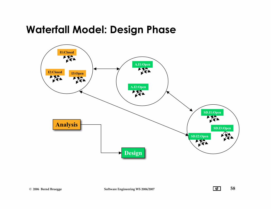
Waterfall Model: Design Phase
I1:Closed
I2:Closed I3:Open
A.I1:Open
A.I2:Open
SD.I1:Open
SD.I2:Open
SD.I3:OpenAnalysis
Design
Analysis
59© 2006 Bernd Bruegge Software Engineering WS 2006/2007
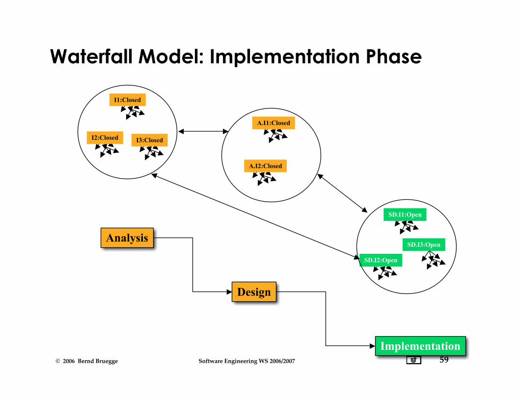
Waterfall Model: Implementation Phase
I1:Closed
I2:Closed I3:Closed
A.I1:Closed
A.I2:Closed
SD.I1:Open
SD.I2:Open
SD.I3:Open
Implementation
Design
Analysis
60© 2006 Bernd Bruegge Software Engineering WS 2006/2007
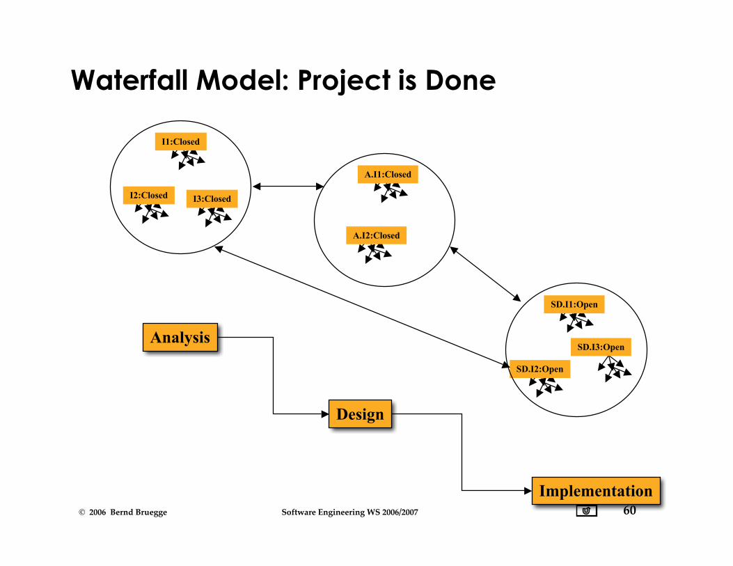
Waterfall Model: Project is Done
I1:Closed
I2:Closed I3:Closed
A.I1:Closed
A.I2:Closed
SD.I1:Open
SD.I2:Open
SD.I3:Open
Implementation
Design
Analysis
61© 2006 Bernd Bruegge Software Engineering WS 2006/2007
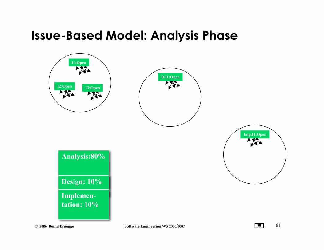
Issue-Based Model: Analysis Phase
I1:Open
I2:Open I3:Open
D.I1:Open
Imp.I1:Open
Analysis:80%
Design: 10%
Implemen-tation: 10%
62© 2006 Bernd Bruegge Software Engineering WS 2006/2007
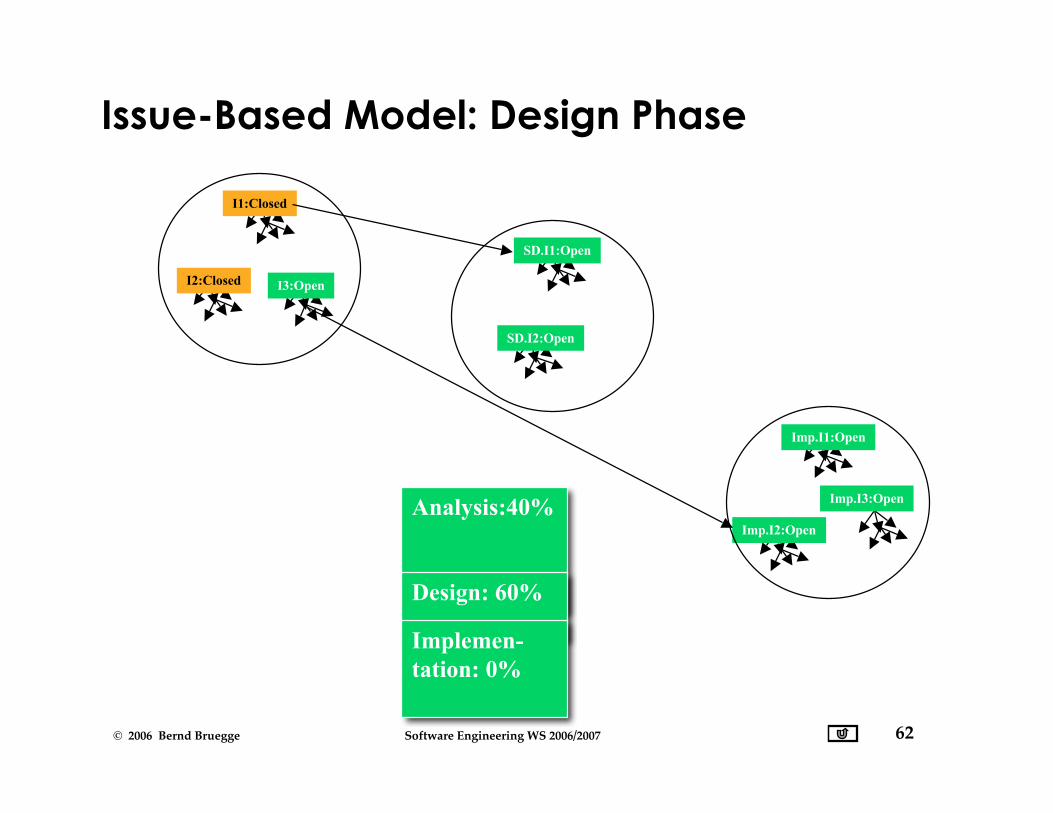
Issue-Based Model: Design Phase
I1:Closed
I2:Closed I3:Open
SD.I1:Open
SD.I2:Open
Imp.I1:Open
Imp.I2:Open
Imp.I3:OpenAnalysis:40%
Design: 60%
Implemen-tation: 0%

63© 2006 Bernd Bruegge Software Engineering WS 2006/2007
Issue-Based Model: Implementation Phase
I1:Open
I2:Closed I3:Closed
A.I1:Open
A.I2:Closed
SD.I1:Open
SD.I2:Closed
SD.I3:OpenAnalysis:10%
Design: 10%
Implemen-tation: 60%
64© 2006 Bernd Bruegge Software Engineering WS 2006/2007
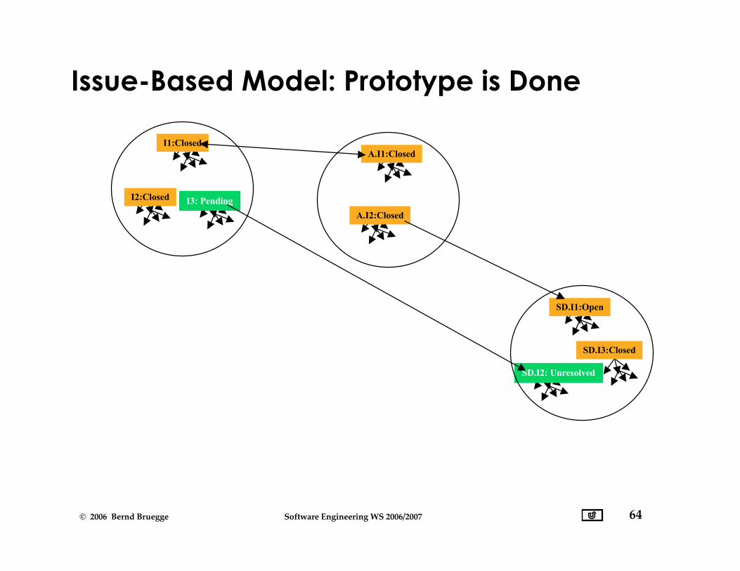
Issue-Based Model: Prototype is Done
I1:Closed
I2:Closed I3: Pending
A.I1:Closed
A.I2:Closed
SD.I1:Open
SD.I2: Unresolved
SD.I3:Closed

65© 2006 Bernd Bruegge Software Engineering WS 2006/2007
Frequency of Change and Choice ofSoftware Lifecycle Model
PT = Project Time, MTBC = Mean Time Between Change
• Change rarely occurs (MTBC » PT)
• Waterfall Model
• Open issues are closed before moving to next phase
• Change occurs sometimes (MTBC ≈ PT)
• Boehm’s Spiral Model, Unified Process
• Change occurring during phase may lead to iterationof a previous phase or cancellation of the project
• Change is frequent (MTBC « PT)
• Issue-based Development (Concurrent Development)
• Phases are never finished, they all run in parallel.
66© 2006 Bernd Bruegge Software Engineering WS 2006/2007
Summary Unified Process
• Unified Process: Iterative software lifecycle model• Emphasis on early construction of a software architecture• Emphasis on early demonstrations of the system
• Definitions• 4 phases: Inception, Elaboration, Construction, Transition• 7 workflows: Management, environment, requirements,
design, implementation, assessment, deployment.• 5 artifact sets: Management set, requirements set, design
set, implementation set, deployment set
• Iteration: Repetition within a workflow.• A unified process iteration should be treated as a
software project.

67© 2006 Bernd Bruegge Software Engineering WS 2006/2007
• Software life cycle models• Sequential models
• Pure waterfall model and V-model• Iterative model
• Boehm’s spiral model• Unified process
• Entity-oriented models• Issue-based model• Sequential models can be modeled as special cases of
the issue-based model
• Prototyping• A specific type of system model
• Illustrative, functional and exploratory prototypes• Revolutionary and evolutionary prototyping• Time-boxed prototyping is a better term than rapid
prototyping.
Summary

68© 2006 Bernd Bruegge Software Engineering WS 2006/2007
Additional References
• Walker Royce• Software Project Management, Addison-Wesley, 1998.
• Ivar Jacobsen, Grady Booch & James Rumbaugh• The Unified Software Development Process, Addison
Wesley, 1999.
• Jim Arlow and Ila Neustadt• UML and the Unified Process: Practical Object-Oriented
Analysis and Design, Addison Wesley, 2002.
• Philippe Kruchten• Rational Unified Process, Addison-Wesley, 2000.
69© 2006 Bernd Bruegge Software Engineering WS 2006/2007
Additional and Backup Slides
70© 2006 Bernd Bruegge Software Engineering WS 2006/2007
Phase vs. Iteration
• A phase creates formal, stake-holder approvedversions of artifacts (“major milestones”)
• A phase to phase transition is triggered by a businessdecisions
• An iteration creates informal, internallycontrolled versions of artifacts (“minormilestones”)
• Iteration to iteration transition is triggered by a specificsoftware development activity.
71© 2006 Bernd Bruegge Software Engineering WS 2006/2007
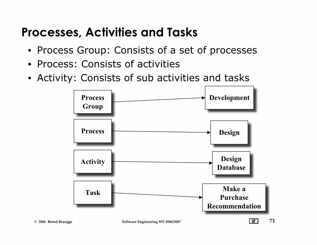
Processes, Activities and Tasks• Process Group: Consists of a set of processes• Process: Consists of activities• Activity: Consists of sub activities and tasks
ProcessGroup
Process
Activity
Development
Design
Task
DesignDatabase
Make aPurchase
Recommendation

72© 2006 Bernd Bruegge Software Engineering WS 2006/2007
Sawtooth Model
SystemRequirementsAnalysis
Implementation
PreliminaryDesign
DetailedDesign
RequirementsAnalysis
UnitTest
PrototypeDemonstration 2
Client
Developer
ClientAcceptance
SystemIntegration
& Test
ComponentIntegration
& Test
PrototypeDemonstration 1
Distinguishes between client and developers
73© 2006 Bernd Bruegge Software Engineering WS 2006/2007
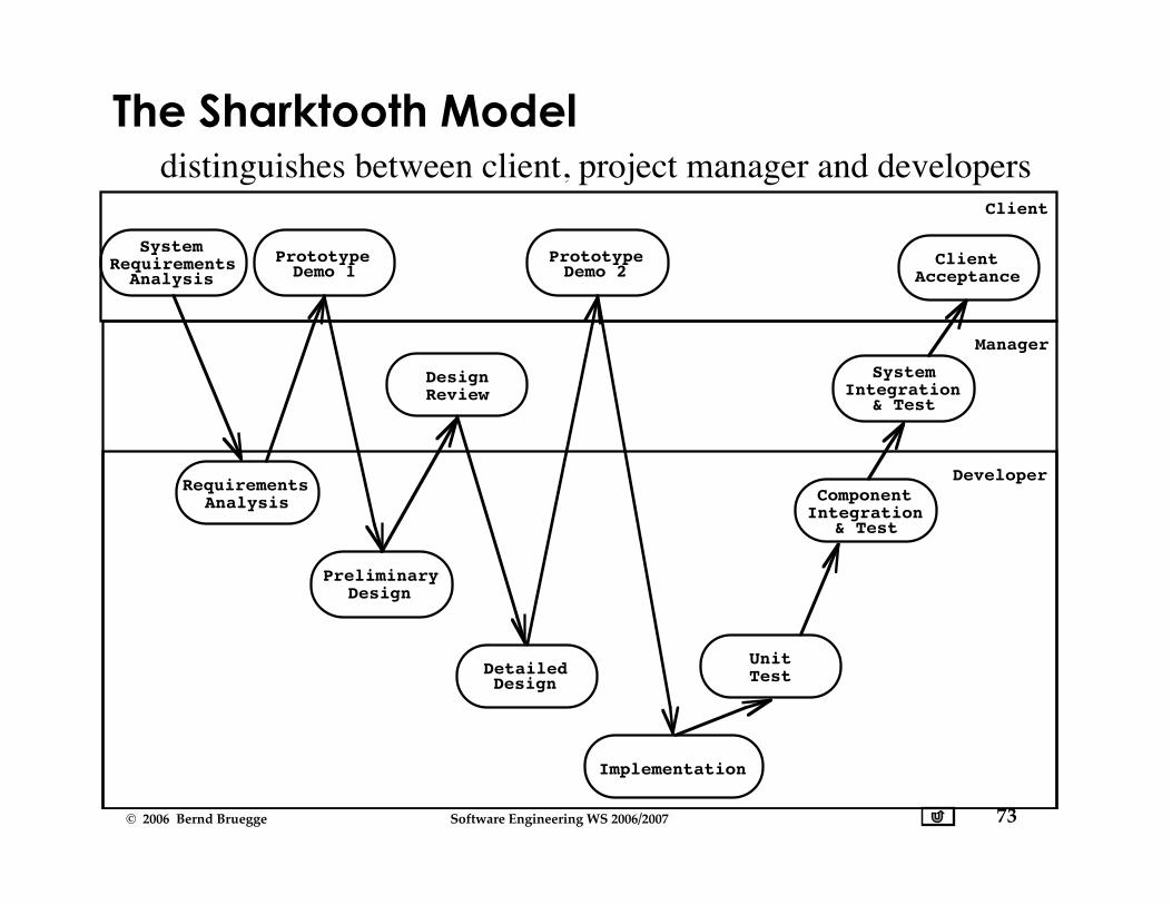
The Sharktooth Model
SystemRequirementsAnalysis
Implementation
PreliminaryDesign
DetailedDesign
RequirementsAnalysis
UnitTest
PrototypeDemo 1
PrototypeDemo 2
Client
Manager
Developer
DesignReview
ClientAcceptance
SystemIntegration
& Test
ComponentIntegration
& Test
distinguishes between client, project manager and developers
74© 2006 Bernd Bruegge Software Engineering WS 2006/2007
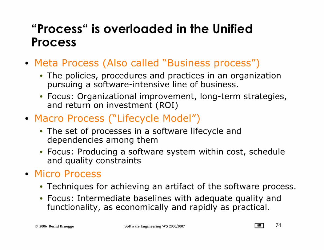
“Process“ is overloaded in the UnifiedProcess
• Meta Process (Also called “Business process”)• The policies, procedures and practices in an organization
pursuing a software-intensive line of business.• Focus: Organizational improvement, long-term strategies,
and return on investment (ROI)
• Macro Process (“Lifecycle Model”)• The set of processes in a software lifecycle and
dependencies among them• Focus: Producing a software system within cost, schedule
and quality constraints
• Micro Process• Techniques for achieving an artifact of the software process.• Focus: Intermediate baselines with adequate quality and
functionality, as economically and rapidly as practical.
75© 2006 Bernd Bruegge Software Engineering WS 2006/2007
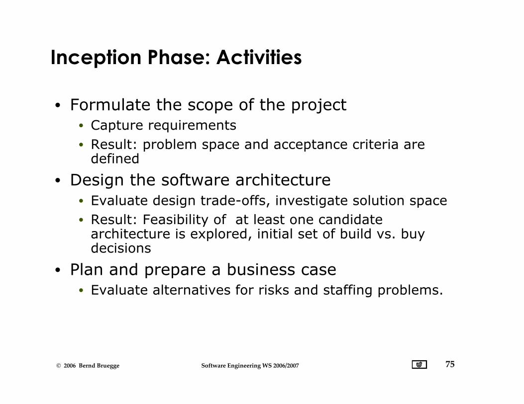
Inception Phase: Activities
• Formulate the scope of the project• Capture requirements• Result: problem space and acceptance criteria are
defined
• Design the software architecture• Evaluate design trade-offs, investigate solution space• Result: Feasibility of at least one candidate
architecture is explored, initial set of build vs. buydecisions
• Plan and prepare a business case• Evaluate alternatives for risks and staffing problems.

76© 2006 Bernd Bruegge Software Engineering WS 2006/2007
Elaboration Phase: Activities
• Elaborate the problem statement (“vision”)• Work out the critical use cases that drive technical and
managerial decisions
• Elaborate the infrastructure• Tailor the software process for the construction
stage, identify tools• Establish intermediate milestones and evaluation
criteria for these milestones.• Identify buy/build problems and decisions• Identify lessons learned from the inception
phase• Redesign the software architecture if necessary
77© 2006 Bernd Bruegge Software Engineering WS 2006/2007
Construction Phase: Activities
• Resource management, control and processoptimization
• Complete development• Test against evaluation criteria• Assess releases against acceptance criteria.

78© 2006 Bernd Bruegge Software Engineering WS 2006/2007
Transition Phase: Activities
• All the activities of deployment-specificengineering
• Commercial packaging and production• Sales rollout kit development• Field personnel training
• Assess deployment baselines against theacceptance criteria in the requirements set.

79© 2006 Bernd Bruegge Software Engineering WS 2006/2007
Inception Phase: Evaluation Criteria
• Do all stakeholders concur on the scopedefinition and cost and schedule estimates?
• Are the requirements understood?• Are the critical use cases adequately modeled?
• Is the software architecture understood?• Are cost, schedule estimates, priorities, risks
and development processes credible?• Is there a prototype that helps in evaluating the
criteria?

80© 2006 Bernd Bruegge Software Engineering WS 2006/2007
Elaboration Phase: Evaluation Criteria
• Apply the following questions to the results ofthe inception phase:
• Is the problem statement stable?• Is the architecture stable?• Have major risk elements have been resolved?• Is the construction plan realizable?• Do all stakeholders agree that the problem solved if
the current plan is executed?• Are the actual expenses versus planned expenses so
far acceptable?

81© 2006 Bernd Bruegge Software Engineering WS 2006/2007
Construction Phase: Evaluation Criteria
• Apply the following questions to the results ofthe construction phase:
• Is there a release mature enough to be deployed?• Is the release stable enough to be deployed?• Are the stakeholders ready to move to the transition
phase?• Are actual expenses versus planned expenses so far
acceptable?
82© 2006 Bernd Bruegge Software Engineering WS 2006/2007
Transition Phase: Evaluation Criteria
• Is the user satisfied?• Are actual expenses versus planned expenses so
far acceptable?
83© 2006 Bernd Bruegge Software Engineering WS 2006/2007
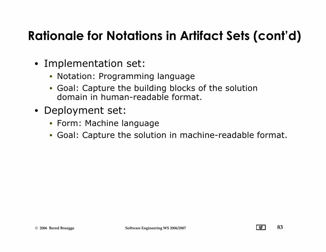
Rationale for Notations in Artifact Sets (cont’d)
• Implementation set:• Notation: Programming language• Goal: Capture the building blocks of the solution
domain in human-readable format.
• Deployment set:• Form: Machine language• Goal: Capture the solution in machine-readable format.
84© 2006 Bernd Bruegge Software Engineering WS 2006/2007
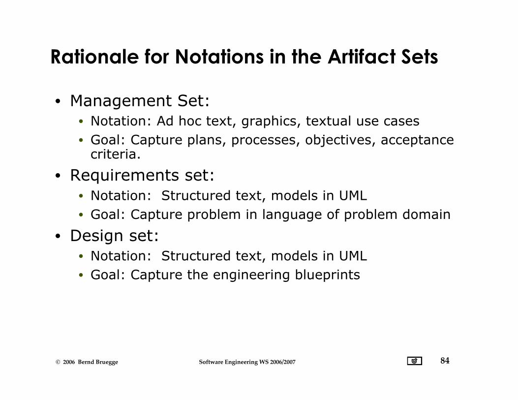
Rationale for Notations in the Artifact Sets
• Management Set:• Notation: Ad hoc text, graphics, textual use cases• Goal: Capture plans, processes, objectives, acceptance
criteria.
• Requirements set:• Notation: Structured text, models in UML• Goal: Capture problem in language of problem domain
• Design set:• Notation: Structured text, models in UML• Goal: Capture the engineering blueprints
85© 2006 Bernd Bruegge Software Engineering WS 2006/2007
Workflows in the Unified Process
• Management workflow• Environment workflow• Requirements workflow• Design workflow• Implementation workflow• Assessment workflow• Deployment workflow

86© 2006 Bernd Bruegge Software Engineering WS 2006/2007
Managing Projects in the Unified Process
• How should we manage the construction ofsoftware systems with the Unified Process?
• Treat the development of a software system with theUnified Process as a set of several iterations
• Some of these can be scheduled in parallel, othershave to occur in sequence
• Define a single project for each iteration• Establish work break down structures for each of the 7
workflows.

87© 2006 Bernd Bruegge Software Engineering WS 2006/2007
Industry Distribution across Maturity Levels(State of the Software Industry in 1995)
Maturity Level Frequency
1 Initial 70%2 Repeatable 15%3 Defined < 10%4 Managed < 5%5 Optimizing < 1%
Source: Royce, ProjectManagement,
P. 364

88© 2006 Bernd Bruegge Software Engineering WS 2006/2007
Insert: Types of Prototypes
• Illustrative Prototype• Develop the user interface with a set of storyboards• Implement them on a napkin or with a user interface
builder (Visual Basic, Revolution...)• Good for first dialog with client
• Functional Prototype• Implement and deliver an operational system with
minimum functionality• Then add more functionality• No user interface
• Exploratory Prototype ("Hack")• Implement part of the system to learn more about the
requirements• Good for paradigm breaks.
89© 2006 Bernd Bruegge Software Engineering WS 2006/2007
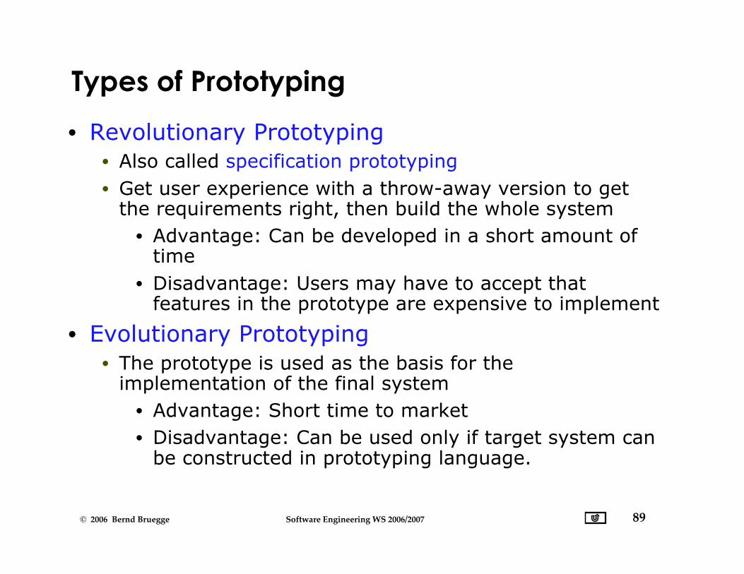
Types of Prototyping
• Revolutionary Prototyping• Also called specification prototyping• Get user experience with a throw-away version to get
the requirements right, then build the whole system• Advantage: Can be developed in a short amount of
time• Disadvantage: Users may have to accept that
features in the prototype are expensive to implement
• Evolutionary Prototyping• The prototype is used as the basis for the
implementation of the final system• Advantage: Short time to market• Disadvantage: Can be used only if target system can
be constructed in prototyping language.
90© 2006 Bernd Bruegge Software Engineering WS 2006/2007
Prototyping vs Rapid Development
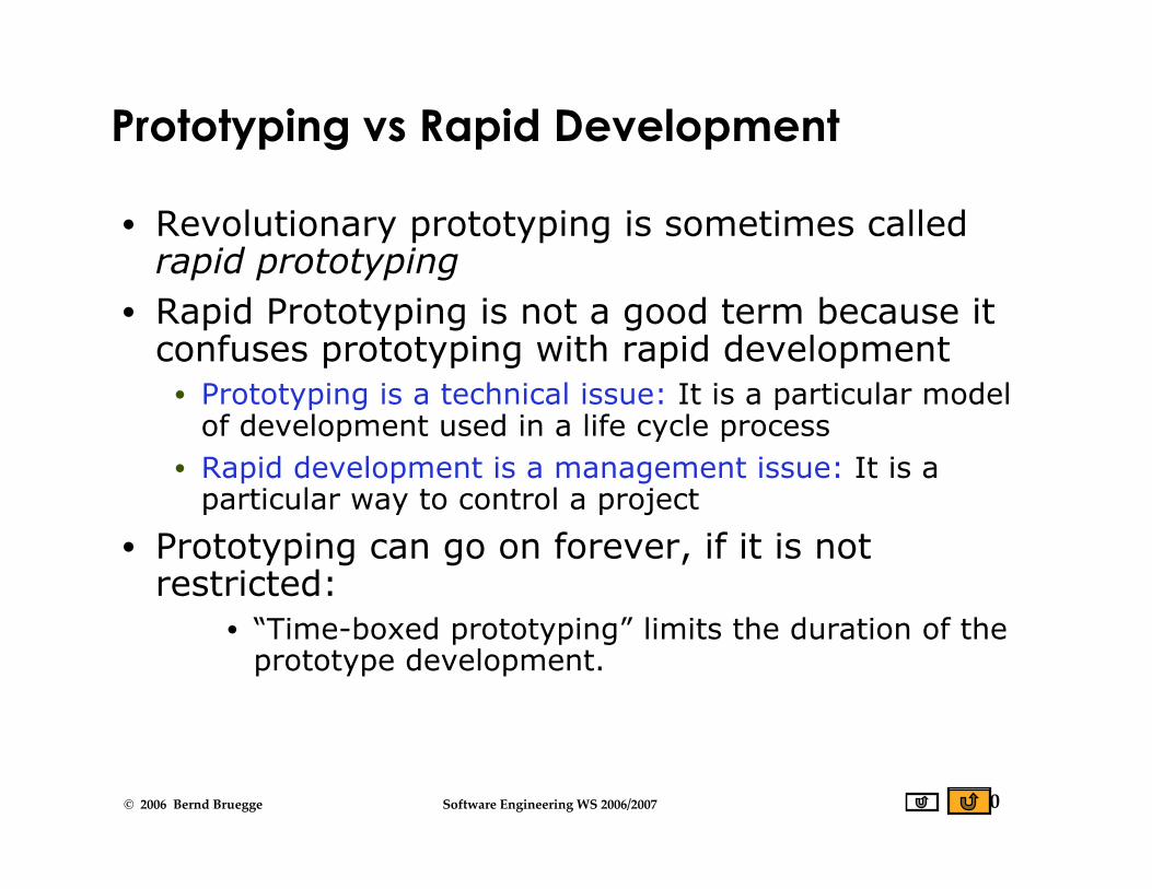
• Revolutionary prototyping is sometimes calledrapid prototyping
• Rapid Prototyping is not a good term because itconfuses prototyping with rapid development
• Prototyping is a technical issue: It is a particular modelof development used in a life cycle process
• Rapid development is a management issue: It is aparticular way to control a project
• Prototyping can go on forever, if it is notrestricted:
• “Time-boxed prototyping” limits the duration of theprototype development.

91© 2006 Bernd Bruegge Software Engineering WS 2006/2007
References
• Readings used for this lecture• [Bruegge-Dutoit] Chapter 12• [Humphrey 1989] Watts Humphrey, Managing the
Software Process, SEI Series in Software Engineering,Addison Wesley, ISBN 0-201-18095-2
• Additional References• [Royce 1970] Winston Royce, Managing the
Development of Large Software Systems, Proceedings ofthe IEEE WESCON, August 1970, pp. 1-9
• SEI Maturity Questionaire, Appendix E.3 in [Royce 1998],Walker Royce, Software Project Management,Addison-Wesley, ISBN0-201-30958-0

92© 2006 Bernd Bruegge Software Engineering WS 2006/2007
Movie of Escher’s Waterfall Model
Escher for Realhttp://www.cs.technion.ac.il/~gershon/EscherForRealWaterfallFull.avi(C) Copyright 2002-5 Gershon Elber,Computer Science Department,Technion
93© 2006 Bernd Bruegge Software Engineering WS 2006/2007
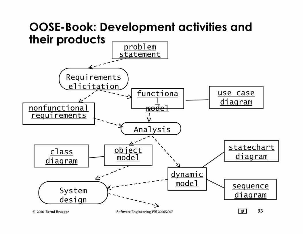
OOSE-Book: Development activities andtheir products
Requirementselicitation
Analysis
Systemdesign
problemstatement
functional
modelnonfunctionalrequirements
objectmodel
dynamicmodel
classdiagram
use casediagram
statechartdiagram
sequencediagram

94© 2006 Bernd Bruegge Software Engineering WS 2006/2007
OOSE- Development activities (cont’d)Systemdesign
Objectdesign
Implemen-tation
objectdesignmodel
designgoals
subsystemdecomposition
sourcecode
Testingdeliverable
system
classdiagram
Related Documents