NASA Technical Paper 3198 1992 National Aeronautics and Space Administration Office of Management Scientific and Technical Information Program Software Design for Automated Assembly of Truss Structures Catherine L. Herstrom, Carolyn Grantham, Cheryl L. Allen, William R. Doggett, and Ralph W. Will Langley Research Center Hampton, Virginia https://ntrs.nasa.gov/search.jsp?R=19920019132 2018-07-14T03:34:35+00:00Z

Welcome message from author
This document is posted to help you gain knowledge. Please leave a comment to let me know what you think about it! Share it to your friends and learn new things together.
Transcript
NASATechnical
Paper3198
1992
National Aeronautics andSpace Administration
Office of Management
Scientific and Technical
Information Program
Software Design forAutomated Assemblyof Truss Structures
Catherine L. Herstrom,
Carolyn Grantham,
Cheryl L. Allen,
William R. Doggett,
and Ralph W. Will
Langley Research Center
Hampton, Virginia
https://ntrs.nasa.gov/search.jsp?R=19920019132 2018-07-14T03:34:35+00:00Z

The use of tradeinarks or names of manufacturers in this
report is for accurate reporting and does not constitute an
official endorscment, either expressed or implied, of such
products or manufacturers by the National Aeronautics and
Space Administration.

Abstract
Concern over limited extravehicular and intravehicular activitiy time has
increased the interest in performing in-space assembly and construction op-erations with automated robotic systems. A technique being considcred at
Langley Researrh Center is a supervised-autonomy approach, whieh caT_ bemonitored by art Earth-based supervisor that intervenes only wh.en the au-
tomated system encounters a problem. A test-bed to support evabtation of
the hardware and software requirements for supervised-autonomy assembly
methods has been developed. This report dcscribcs the design of the software
system necessary to support the assembly process. The system is implemented
and successfully assembles and disassembles a planar tetrahedral truss struc-ture. The software is hierarchical and supports both automated assembly
operations and supervisor error-recovery procedures, including the capability
to pause and reverse arty operation. The software design serves as a model
for the development of software for" more ._'ophisticated automated systems
and as a test-bed for evaluation of new cor_cepts and hardware components.
Introduction
A number of future space inissions will require
large truss structures, some of which will supportfunctional surfaces such as antennas, reflectors, and
aerobrakes. Two examples of such missions are
shown in figure 1. Figure l(a) is an astronomi-
cal observatory, and figure l(b) is a Mars mission
vehicle with a truss-supported aerobrake. Consid-
erable effort has been expended during the past10 years toward establishing a capability of assem-
bling large space structures on orbit. (refs. 1 and 2).
A shuttle flight experiment of a large truss structure
(ref. 3) and recent truss-supported reflector designs
(ref. 4) are aimed at astronaut assembly. However,current concern over limited astronaut EVA (extra-
vehicular activity) and IVA (intravehicular activity)
time (ref. 5) has increased the interest in performing
in-space assembly and construction with automated,robotic systems. One particularly attractive alterna-
tive utilizes the operator as a supervisor or system
monitor, called upon only when the robotic system
requires intervention or assistance. This mode of op-eration, known as supervised autonomy, eliminates
planned EVA for construction and reduces IVA. Su-
pervised autonomy has the advantage that it can be
performed from any location, including the ground,since it does not require the performance of time-
critical active functions by the operator.
To date, very little effort has been directed to-ward the development of automated robotic methods
for large truss structures. Langley Research Center
(LaRC) has developed a unique facility to support
the first detailed study of automated structural as-
sembly (ref. 6). The interdisciplinary effort focuseson gaining practical experience in the automated as-
sembly of large, generic, truss-structure hardware de-
signed for robotic operations.
The objective of this report is to describe the
requirements and design of the software that. per-forms the automated assembly of the truss structureand to discuss the interface and interaction between
the soft.ware program, the system hardware, and the
operator. An initial version of the automated as-
sembly systenl has t)een developed and is currentlyoperational. Considerable experience has been ac-
cumulated in the assembly and disassembly of a
102-lnember tetrahedral truss structure (refs. 6 to 8).
The assembly system components are described, anda narrative of the assembly process is given, to serve
as a basis for the description of the software and its
functions. The actual implenmntation of the design
is discussed in appendix A. Finally, an evahmtion of
the software system operation and ext)erience is pre-sented. The purpose of the evaluation is to discuss
the success of the design in satisfying the system re-
quirements. A glossary' of terms relative to the sub-
ject matter discussed in this paper is contained in
appendix B.
Symbols and Abbreviations
AP approach point
AP_CAN canister approach point
CAP capture loeations (CAP1,
CAP2)
CLOSE, LOCK, individual actuatorEXTEND commands
GP grasp point
GP_CAN canister grasp point

INSTALL.REMOVE,, [ACQLIRE, PROP
IP
NASREM
Pitch, Roll, Yaw
R,
REM
STORAGE
STORAGE_AP
TRAY
TRAY_AP
TRIPOD
X,Y,Z
".L', tl, Z
0
assembly functions
transition point
NASA/NBS standardreference model
pitch, roll, and yaworientations of robot arm
radius
removal locations (REM1,
REM2)
storage-tray grasp point
approach point to
storage-tray canister
working-tray grasp point
approach point toworking-tray canister
capture point for pyramidinstallation
x, y, and z positions ofrobot arm
coordinate locations
ahmg x-, y-, and z-axes
angle of rotation, (leg
Assembly Facility Hardware
Figure 2(a) is a scheinatic of the atttomated as-
sembly facility, and figure 2(b) is a photograph ofthe actual hardware system. The facility consists of
a robot arm, a motion base, a truss, an end effector,
and strut storage trays. It uses commercially avail-
able equipnlent so that it can be easily modified. Thehardware system is a ground-based research tool de-
signed to permit evaluation of assembly techniques,
strut joining and end-effector components, computersoftware architecture, and operator interface require-
ments that are necessary for automate(t in-space op-
erations. A more complete description of the facility
hardware and performance characteristics is given inreferences 9 to 11.
Robot Arm
The robot arm is a six-degree-of-freedom indus-
trial manipulator selected for it.s reach envelope, pay-
load capacity, positioning repeatability, and reliabil-
ity. The robot-arm computer is based on a 68000
microprocessor, and all robot-arm motions are pro-
grammed in a modified BASIC programnling lan-
guage supplied by the manufacturer.
Motion Base
The motion base includes a linear translational
carriage and a rotating turntable. The robot arm is
mounted on the carriage, which has approxinmtely20 ft of travel in both the z and y directions, with
a positioning accuracy of 0.002 in. The truss struc-ture is assembled on a rotating turntable capable of
six revolutions of travel and a positioning accuracyof 0.01 in. at a radial distance of 20 ft (0.0024°).Motion-base drive motors on the three axes are
commanded by an Intel 80286 microprocessor-basedindexer.
Truss
A planar tetrahedral truss, such as the model
shown in figure 3, was selected for initial assemblystudies because it is representative of the type of truss
structures required for large antennas, reflectors, and
aerobrakes. The truss is specifically designed for
automated assembly and includes regular hexagonal
rings. Core struts are those that connect the top faceto the bottom face. All struts are nominally 6.6 ft
long and 1 in. in diameter. The complete structure
has 102 struts and 31 nodes. Assembly begins by
connecting struts to three nodes that are premountedon the motion-base turntable.
The truss node and joint connectors are shown
in figure 4. Two joint connectors are bonded to agraphite-epoxy tube to form a strut. The joint has
a connector section which, during assembly, is in-serted into a node-mounted receptacle. A locking
nut is turned by the end effector to draw the connec-
tor phmger toward the connector face of the strut,
securing the joint. The alignment arid grasp adapteris used to grip the strut and align it precisely withthe end effector.
End Effector
The end effector is a specialized tool mounted onthe robot arm that performs all strut installation and
removal operations. Figure 5(a) is a schematic of
the end effector, and figure 5(b) is a photograph ofthe end effector and its components. The strut is
grasped by a set of strut holders that close around
the alignment arid grasp adapters (figs. 4 and 5) thatare bonded to the strut tube. The strut holders are
mounted on a platform that is extended for insertion
of thestrut into tile nodereceptacles.A strut is in-stalledinto tile trussby movingtile endeffectortoa positionwherethereceptaclefingers(fig.5(t)))areableto grapplethenodereceptacle.Actuatorsclosethefingersaroundthenodereceptacleandpassivelyalign the endeffectorand strut with the nodere-ceptacle.Afteralignment,theplatformisextendedandinsertsbothjoint connectorsintothereceptacles,wheretheyareheldwhilethe lockingnutsaretight-enedwithnut driverson theendeffector.Thestrutholdersareunlatchedandtile platformisretracted.Thereceptaclefingersarethenopenedto releasethestructure.
All end-effectorcomponentsand actuatorsare'equippedwith simplesensors,suchasmicroswitchesand linear potentiometers,so that the computerprogramcanmonitorthe operationsandalert theoperatorif a problemoccurs.Smallvideocanlerasaremountedoneachendof tileendeffectorto permitoperatormonitoringof conlponentflmctions.
A six-axisforce-torquesensor(FTS) is re(rantedon thewristof therobotarnl to measureforcesandmomentsactingon theendeffeetor.TheoutputoftheFTSis usedto commandsmallrobot-armmove-mentsin a directionthat will "zero"the measuredforcesandmoments.Thismovementis usedto re-ducetheloadson theendeffectorandto enabletheend-effectorcomponentsto operatefreely.
Trays
The trussstrutsarcstoredin ninetrays,whicharestackedin theworkingcanisterdirectly behindtherobotarm(figs.2(a)and2(b)). Emptytraysaretransferredbypickingthemupwith theendeffectorand movingthemto the storagecanister,which islocatedon onesideof the robot arm. Thestrutsare removedfroln the tray by positioningthe endeffectoroverthestrut,extendingtheplatformsothat.the strut holderscontactthe alignmentand graspadapters,andlatchingtile strut to theendeffector.Theplatfornlis thenretractedto withdrawtile strutfrom thetray. Eachtray hascylindricalhandlesonbothends;thesehandlesarefitted with positioningandalignmentadapters,whichallowtheendeffectorto pickupemptytraysfi'omtheworkingcanisterandtransferthemto thestoragecanister.
Assembly Process
Theassemblyprocessbeginswhentheendeffec-tor acquiresthefirst strut fromthetop tray ill theworkingcanister. Oncethe strut is acquired,themotionbaseis positionedsothat therobotarmcan
connecttile strut to thestructure. Therobotarm,movingthroughasequenceofpredeterminedpoints.positionsthestrutat.itspointofinstallationorgrasppoint. Theendeffectorthen insertsand locksthestrut intoplace.Finally,therobotarmreturnst.otheworkingcanisterto retrieveanotherstrut. Thisbasicoperationalsequenceis followedfor the installationof all struts.Eachpart of thesequenceisdetailedmtile sectionsthat follow.
Acquiring a Strut From the Tray
Each strut has a preassigned tray nmnber and a
slot. location. The end effector is positioned at the
canister approach point (a t)redefined point at the
top of the working canister), which is directly over
the desired strut in the tray. lXeceptacle fingers are
closed to prevent collisions with preattached nodes
on adjacent struts remaining in the tray. The end ef-lector is lowered to the canister grasp point (the level
of the tray containing the strut), so that extending
the platform causes the strut hohters to lightly con-
tact the strut alignment and grasp adapters. Whenthe platform extends, the force-torque algorithm bal-
ances the forces and moments acting on the end effec-
tor while slowly applying a maximum of 20 ltff in thedownward direction to close the strut holders. After
the strut holders are latched, the forces and torques
are ret)alanced. The platform is then retracte(l, and
the strut is lifted from the working canister. From
the working canister grasp point, the strut is carried
to the canister approach point, where lhe receptacle
fingers are opened in preparation for the installationoperation.
Motion-Base Moves
Associated with the installation of each strut are
the carriage and turntable positions (x, y, and 0)
required for installation. The curren! carriageand turntable positions, the required carriage and
turntal)le t)ositions for tile strut being installed, an(l
the status of the structural asseml)ly are used to de-
termine if the carriage and/or robot arm will collide
with any struts that arc currently assembled. Tilemotion-base repositioning commands can be per-
formed in any order. All motion-base moves are per-
fornled with the rot)ot arm positioned at the can-
ister approach point to minimize the distance the
robot arm extends toward the truss; this position-ing reduces chances for collision. The motion-I)ase
collision-avoidance algorithm is described ill detailin the section "Motion-Base and Collision-Avoidance
Design."
Robot-Arm Paths
The robot arm traverses a predetermined path to
deliver tile strut to the proper location and orienta-tion in the structure. There are three strut instal-
lation cases: direct, capture sequence, and pyramid
completion. For direct installation, tile end effector
and strut are carried directly to the grasp point, apredetermined location where tile strut can be in-stalled into the structure. Direct installation entailseither the insertion of a strut, between two fixed nodes
already in the structure or the installation of a strutwith a preattached node at one end. For struts with
prcattached nodes, the end effector only operates the
receptacle fingers and locking component at one endand leaves tile strut-node combination cantilevered
from the fixed node to which it is installed in the
structure. The installation of a strut with a pre-
attached node creates the capture-sequence installa-
tion, which requires the end effeetor to install a strutbetween the free end of a cantilevered strut (deflected
by gravity) and another node in the structure. For
this case, the end effector must be positioned so thatthe receptacle fingers on one end grasp and capturethe cantilevered node. The robot arm is then moved
so that the receptacle fingers on the opposite end can
grasp the node in the structure and so that both endsof tile strut can be inserted and locked into place.
The pyramid-completion installation case per-
forms the installation of a third strut into a pyra-mid substructure. This installation is similar to the
capture-sequence installation, except that the nodebeing captured already connects two struts. For the
pyramid-completion installation, t.hc deflections due
to gravity are not as large as in the capture-sequence
installation. The robot arm is again moved to the
grasp point after node capture of the two connectedstruts where the strut is inserted; this move com-
pletes the pyramid configuration.
In addition to the three installation cases, there
are two removal cases that arc necessary for dis-
assembly: free and direct. The free removal caseinvolves cantilevered struts with preattached nodes
that are deflected as a result of gravity. Tile robot
arm must move to a predetermined point and close
the receptacle fingers to capture the cantilevered end.It then continues to a second predetermined point
to avoid node receptacles of installed struts before
proceeding to the grasp point, where the strut isremoved from the structure. The direct removal case
applies to all other struts. The robot arm traversesa straight path directly to the grasp point. The end
effector receives commands during the path sequence
4
to perform tasks such as closing receptacle fingers to
capture nodes at the proper locations.
End-Effector Operations
When the robot arm reaches the grasp point forthe strut, control is transferred to the end effector. A
strut installation includes closing the receptacle fin-
gers on the node receptacles, extending the platform
to insert the strut into the receptacles, locking thestrut into place, unlatching the strut from the end
effector, retracting the platform, and opening the re-
ceptacle fingers. Sensors are monitored after each
step, and the sequence does not proceed unless the
operation is successful.
System Software Requirements
The autonmted assembly system software was de-veloped to support projected assembly system re-
quirements. These requirements were generated by
an interdisciplinary group of hardware designers, pro-grammers, engineers, and prospective users of the
system. The participation of a wide range of dis-
ciplines resulted in a software design that has notchanged appreciably during the evolution of the sys-
tem. These system requirements are discussed fur-
ther in the following section, and the requirementsfor the three devices motion base, robot arm, and
end effector are discussed in subsequent sections.
Overall Requirements
The overall system requirements are as follows:
(1) to assemble and disassemble the tetrahedral truss
in an automated mode; (2) to provide sufficient in-
formation displays and control capability to supporta supervised autonomy mode of operation; (3) t.o in-
terface with advanced systems, such as plaimers; and
(4) to accommodate assembly system hardware and
procedural upgrades.
The requirement to provide the capability for
a fully automated assembly and disassembly estab-
lished the need to know the predetermined condi-
tions that direct the assembly process, the current
state of all system hardware devices, and the currentstate and location of every strut in the truss struc-
ture. Predetermined conditions include the geometry
of tile structure, path sequences, strut storage infor-
mation, motion-base moves for strut installation, and
potential obstructions during motion-base moves.The software must include algorithms and procedures
for gravity-deflected strut capture, motion-base col-
lision avoidance, and error recovery. When perform-
ing the assembly task, the software must command

andsequencetile motionbase,robotarm,andend-effeetorhardware,andmustprovideinterfacesforthesupervisor.Becauseeachofthesystemhardwarede-vicesisan independentsubsystemthat mustbeco-ordinatedduringassenfl)lyoperations,thesoftwaredesignmustaccommodateadistributedarchitectureto providelocaldevicecomponentcontrol.
Thesoftwarerequirementsarcdrivenby a needfor a userto monitor and effectivelymanagetheoperationof the automatedsystem. The role ofthe systemsoftwareuserandthe userinterfaceisthereforedefinedasfollows:
1. Theuserisconsideredto bea supervisorbe-causesystemoperationis primarilyin anau-tomatedmode.
2. Supervisorinteractionisrequiredonly for er-ror recovery.
3. Supervisormonitoringis supportedwith asmuchtaskandstatusinformationaspossible.Thisinformationmustbeclearandconcise.
4. Thesupervisormayinterveneat.anytime tochangetasks or requestinformation. Thisinterventionincludespausingthe automatedsequencesto lookat videodisplaysorassemblydetailsbeforeeitherresumingorreversingthetask.
5. Thesupervisorhasoverridecapabilityoverallautomatedfunctions.
6. Thesupervisorisnot.responsiblefor dataandstatusupdatesresultingfromcommandedac-tions.Theseupdatesoccurautomatically.
7. A secondarymanualor checkoutmodeallowsthesupervisoraccessto all levelsofcommandsanddatasothat all automatedflmctionscanbeduplicatedand analyzed.Systeinstatuschecksare performedprior to executionofall supervisorcommandsto avoiddamagingactions. Accessto the lowercommandlev-elsis restrictedto experiencedor authorizedsupervisors.
8. Threemodesof supervisorinput arerequired:keyboard, command file, and assembly-sequencefile. Tile keyboardmoderequiresthe supervisorto entereachcommandman-ually.Thecommand-filemodealleviatessometyping by allowingthe supervisorto createa file of theactualcommandsthat wouldbeenteredinteractively.Thecommand-fileexe-cutionshouldparallelthe performanceof thesystemin thekeyboardmode.Theassembly-sequencefileisa higherlevelcommandfile. It
containsgeneralassemblyanddisassemblyse-quences,includinganorderedlist ofthestrutsto beinstalledor removed.Thesystemtrans-latesthe assembly-sequencefile into a com-mandfileoftileactualsystemcommands.Thesystemallowsthe supervisorto performon-linecreation,modification,anderrorrecoveryof thecommand-andassembly-sequencefiles.
The third overallrequirementis the ability tointerfacewith advancedsystems. Undercurrentconsiderationare knowledge-based,expert systemcontrolofassemblyflmctions,path-planningtoolsfortherobotarm,andmachinevisionto providerobustsystemoperation.
Thesoftwaresystemnmstaccommodateassemblysystemhardware,computerhardware,andprocedu-ral upgradesthat resultfromoperationalexperience.Oneproceduralupgradethat becameapparentdur-ingthedevelopmentprocesswastheneedto reversetheassemblyprocessaftera pauseorunresolveder-ror. Thiscapabilityimprovessupervisorconfidencein the automatedsyst.emoperationsand providesapowerflflerror-recoverytechnique.Whenan errorcannotbecorrected,the systemautomaticallyini-tiatesa reversesequenceof commandsandrelievesthesupervisorof havingto remembertheproperse-quence.This reversesequenceimposesa significantburdenonthesoftware,however,becausethereversesequenceis not necessarilytheexact,oppositeof theforwardsequence.An exampleof the ability to ac-commodatenewhardwareinvolvestheincorporationofnewendeffectorsforadditionalassemblytasksandadvancedoperations.
Motion-Base Requirements
Themotionbasemustpositionthecarriageandrotatingturntat)letothecorrectx, y, and 0 positions.The z, y, and 0 positions are expressed as eitherabsolute locations or moves relative t.o the current
position. The x, y, and 0 moves may execute inany order, and each move is verified before the next
move is begun. The motion base should be able
to move to predefined locations or receive a direct
move instruction from the supervisor. Before anymovement of the motion bases, collision-avoidance
logic must determine the order of moves that will
keep the motion base from hitting the assembledstruts.
A pause option for the motion base includes
the ability to manually adjust the current position.When reversing the motion base, the forward se-
quence is retraced.
5
Robot-Arm Requirements
The robot arm is requiredto traversepre-determinedpathsforstrut installationandremoval,for movingthe traysto andfromthestoragecanis-ter, andfor changingthe endeffector.Therobot-armprogramnmstbeableto accesstheend-effectorcommandsdirectlyto avoidobstaclesandperformcapture tasks.
For the strut paths, the robot arm is required to
automatically move sequentially in either direction
through a series of intermediate positions that de-pend on the strut installation position in the truss.
There arc 19 unique paths used during the assemblyof the truss structure. The software must be able to
select the correct path for each strut, including the
capture of gravity-deflected cantilevered struts.
The robot-arm reverse is not always the opposite
of the forward sequence for the strut paths. Detailsof the reverse are discussed in the section "Robot-
Arm Path Design." The reverse sequences for tray
operations and end-effector changes are exactly op-
posite of their forward sequences. As with the motionbase, the pause option includes the capability for the
supervisor to adjust the robot-arm position.
End-Effector Requirements
The end-effector software must be able to gen-
erate sequences of actuator commands to performfour basic assembly functions: install, remove, ac-
quire, and drop. The system must be able to ac-
cess the actuator commands, monitor sensor outputs,and perform sensor conflict checking after each actu-
ator conmmnd is executed. The software design must
be able to support various end effectors, such as the
addition of a panel end effector for future assemblyoperations.
End-effector error conditions detected by the sen-
sors are displayed for the supervisor. The super-
visor has the option to manipulate the end-effectoractuators directly, reposition the robot arm to permit
the actuator to function properly, continue execution
when the error is not deemed serious enough to war-rant action, or abort error correction and allow the
system to reverse. For the end-effector functions, the
reverse is not always the exact opposite of the for-
ward sequence. The error-recovery software providesthe option of executing automatically or manually.
The end-effector software must provide direct access
to the robot-arm commands to reposition the robot
arm or to balance the forces and torques acting onthe end effector.
System Software Design
Although the assembly system is intended to op-erate in a fully automated mode, it is imperative that
the supervisor be provided with appropriate internalinformation and have sufficient command access and
authority to deal with assembly problems. For this
reason, the automated assembly system software de-sign is approached primarily from the supervisor's
viewpoint. A command hierarchy makes the control
process simple and orderly. The result is a modularsoftware structure that coincides with the hierarchi-
cal nature of automated operations. The following
sections provide the details of the software design.Appendix A provides some insight into the actual
implementation of the design.
Design Overview
Design Layout
Figure 6 shows the design layout of the automated
assembly program. It comprises four basic levels:administrative, assembly, device, and component.
Because of the natural hierarchy of the assembly pro-
cess, a top-down design philosophy is used; this phi-
losophy causes the highest level commands to appearfirst and successively decomposes to the lowest-level
component commands. The software design process
is based upon the assembly sequence described pre-
viously and the requirement that the supervisor haveaccess to all levels of detail.
The administrative level is involved with the pre-
liminary setup of the system. It allows the supervisor
to examine and modify data and system options. The
command and assembly files can be selected, created,and modified. Also, the supervisor gains access to the
lower levels of the system through the administrativelevel.
The assembly level reflects the automated aspect
of the system. At this level_ the software manages
all the devices, data verification, and error recovery.Command operations at this level for assembly and
disassembly of the truss are all automated. This level
interfaces with a proposed automated task sequenceplanner. The standard operating mode occurs at the
administrative and assembly levels.
The device level gives the supervisor access toeach individual device and to the functions the de-
vice performs. To obtain and install a strut requires
action by three separate devices: the motion base,
the robot arm, and the end effeetor. Decompositionof the commands at the assembly level results in a se-
quential list of device-level commands. The functions
associated with each device are taken directly from
therequirements.Accessto this levelrequiresmoreexpertiseon thepart of tile supervisorandinvolveslessautolnaticcheckingby tile software.
The componentlevel reflectstile hardwareca-pabilityof the currentsystem.Eachof tile devicecommands,suchas the emt-effectorinstall con>mand(INSTALL)decomposesinto individualactu-ator commands(e.g., CLOSE, LOCK, EXTEND)which are the basic tasks perforlned by the hard-
ware. Sensor checking and verification occurs af-
ter execution of each colnponent conunand. This
level is dependent on the specific devices used and
could change if the hardware changes an impor-
tant aspect to consider in the software design andimplementation.
Menu Interface
A menu-driven, rather than a command-driven,interface is used in all effort t.o reduce the numl)er of
comnmnds at. each level and the amount of internal
syst.em ilffornmtion presented to the supervisor. Themenu-driven command structure also accommodates
relatively inexperienced supervisors. Figure 7 shows
the basic menu layout for the system; the layoutwas derived directly from the design in figure 6.
The melmS reflect the actions required to control the
hardware and assembly process.
Each box represents a menu on the supervisor'sdisplay. Menu selections can be designated by ei-
ther tile nuxnber or the first unique characters of theconmland. Tile lines between boxes indicate how a
supervisor traverses the various levels of the system.
Every menu contains "help" to aid inexperienced su-pervisors by providing information about each selec-
tion. As a sele(:tion is made, the item is highlighted.
Tile menus are overlapped on tile screen as they' are
selected (fig. 8) to provide the supervisor with infor-mation from every level. Everything entered by the
supervisor is recorded in a journal file that is awfil-
able for post-test analysis.
Command Decomposition
The nlain menu (figs. 7 and 8) displays tile four
major components of the systenl. Selection 1 (Sys-
tem configuration) allows the system configuration
paranmters and variahle status to be displayed and
modified. Selection 2 (Auto build) initiates auto-mated assembly according to a predetermined as-
sembly sequence contained in a predefined assembly-
sequence file. Selection 3 (Assembly fimctions) allows
access to the manual command mode, which provides
the supervisor with conunand capability at all levels
of tile autonmted system. Selection 4 (File manipu-
lation) permits selection and editing of an automated
assembly-sequence file or a command file; these filesare discussed in the following section.
Selection 3 reveals subsequent hierarchical menus
in which higher level menu conunands are comt)os-ites of lower level nlenu comman(ls. The lowest hwel
menus are the component-oriented commands thai
are directly associated with the hardware of the sys-
tem. All commands incorporate internal, automalie
checking to protect the hardware from supervisor-controlled commands that could resull in hardware
dalnage. As the supervisor works down the menu
hierarchy, control and resl)onsibility shifts from the
automated system to the supervisor. The lower level
menus rely on supervisor expertise: lllereforo, manyof the lowest nlenu levels and some error nlenu selec-
tions are password-protected or have hidden mtqm
options.
The composite conunands are higher level lnenll
entries that initiate a seqltence of colnnlantts It) per-form the selected task. Figure 9 illustrates compos-ite coinmand Fetch and connect. As each command
is executed, the ,_ssociated menu is displayed and
highlighted. This layered menu presentation allows
tile supervisor to moIfitor the sequence of hit'rarchi-
cal conmlands and provides a trace to aid in error
recovery.
An error-recovery menu is displayed to the su-
pervisor when sensor checks indicate that a syslenl
component did not flmction t)roperly. The sysletn
will not proceed until l.he t)rol)lenl is resolved. If
a problem cannot be corrected, error informal ion ispassed back through the s vstenl hierarchy and causesthe commanded actions to reverse their task.
Supervisor Input Mode,s
There are three Inodes of sut)ervisor input: (tirect
keyboard, command file, and assembly-sequence file.
as defined in the requirements. The keyboard intmtinode requires the supervisor to enter eac]l lneilu s('-
lection from the keyboard. The command-file mode
allows tim sut)ervisor to create a text file of the con>
mands as they wouM be entered in the keyboard in-
put mode. Tile system obtains its input from the file,so that the supervisor is freed for nlonitoring. This
freedoin is t)articularly helt)ful for rel)etitive tasks.
A command file is executed through selection 4 (File
manipulation) from the main menu. This m(mu also
allows the supervisor to create a. conmmnd file (Build
command bile) and inodi_ an existing conlmand file{Edit conlmand file) without exiting the program.
Limitedon-linecorrectionof thecommandfile isavailablewhenan illegalcommandis encountered.Executionis suspendedandthe command-fileerrormenuisdisplayed,asshownin figure10.Thecurrentline in the commandfile, the commandcontainingthe error, the next command,and a list of actionsavailableto the supervisorare displayed. In theexampleshown,the currentcommandfile containsan incorrectcommand.The supervisorshouldpickselection1 (Correctcurrentcommand)andwill bepromptedto enteranewcommand.Aftercorrectingthecommandfile, thesupervisorcanexecutethefiletwoways.Selection2 (Re-executecurrentcommand)will executethecorrectedcommand,incrementthecommandfile to the next line, and return to thecommand-fileerror menu. This optionallowsthesupervisorto insert commandsand executethemoneby one. Thesecondwayto initiate executionis by pickingselection3 (Continueexecutionwithcurrentcommand).Thisoptionstartsexecutingatthe correctedcommand,continuesexecutionfromthis point, andexits the command-fileerrormenu.Thisoptionissimilartoselection4(Executethenextcommandandcontinue),but this optionbeginsatthenextcommandandskipsexecutionofthecurrentconlnland.
In situations where many commands need to be
modified, it may be more efficient to abort thecommand-file execution mode and edit the command
file. The command file may be edited without exit-
ing the program by selecting main menu item 4 (File
manipulation).
The third input mode, an assembly-sequence file,executcs like the command-file mode, but the format
is independent of the actual commands entered. Theformat is simplified and the software converts the
file into the commands required by the system. The
assembly-sequence file format is as follows:
Assemble
strutname a
strutname b
Disassemble
strutname c
strutname d
End
The supervisor has the option of creating and modi-
fying these files without exiting the system.
Robot-Arm Path Design
The robot arm has three tasks to perform:
(1) traverse strut paths for installation and removal;
(2) transfer trays between the working and storagecanister; and (3) change the end effector. Transfer-
ring trays and changing the end effector are fairly
straightforward tasks. Traversing the strut path is
more complex because of the intricate orientationsnecessary to locate the strut in the structure without
interference from previously installed struts. Robot-
arm tasks are detailed in the following sections.
Logic ofStrutPath State
The robot-arm path from the strut storage canis-ter to the structure and return has been divided into
segments or path states. The exact path traversed
depends upon the current strut location in the struc-ture. The state is the current coordinate location of
the robot arm (X, Y, Z, Roll, Pitch, Yaw). Thestates defined for this study are illustrated in fig-
ure 11 (GP_CAN AP_CAN, IP, AP, and GP). This
illustration typifies the simplest sequence of moves
required to carry a strut between the canister andthe structure.
The robot-arm rest position and the point at
which it begins a strut retrieval is located immedi-
ately above the canister and is designated the can-ister approach point, AP CAN. The strut is picked
up at the canister grasp point, GP CAN, and car-
ried back to AP_CAN. A transition point, IP, is
passed through before the strut is carried to thestructure approach point, AP. The transition pointis where a transition occurs from a canister-oriented
path, which involves a tray and slot number, to an
installation-oriented path that is dependent on thestrut location in the structure. The approach point
is approximately 4 in. from the grasp point at the
structure, GP, where the strut is actually installed.
Figure 12 is a complete diagram of the robot-arm
state paths, including capture operations. The fig-ure indicates the strut installation and removal cases,
which determine the various paths, as well a.s con-
ditions for performing end-effector actions. Condi-
tional states, denoted by dashed boxes, from AP toGP are special cases required for various strut can-
tilever conditions. The conditional state positions en-
able the robot arm to capture cantilevered struts and
avoid collisions with node receptacles while lining upthe strut at its location in the structure. The states
are represented by solid boxes, and the arrows be-tween the states represent transitions between states.
End-effector receptacle finger actions, as shown by
the ovals,are requiredat variouspointsalongthepath sequence.The robot arm passessequentiallyfrom onestateto the next whenmovingbetweenthe canisterandthe structure.Thearrowheadsin-dicatethedirectionsallowedbetweenstates,condi-tionalstates,andend-effectoractions.Theonlytimethe systemcanterminatebetweenstatesis whenahardwarefailureoccurs.
Whendeterminingtherequiredpathfromstatetostate,thepathswithconditionsareconsideredfirst.Theunconditionedpathis takenonlywhennoneoftheconditionsfor captureoperationsaremet.Casesexistfor whichthe reverseconditionsdonot mirrortheforwardpath. Whentherobotarm is followingapath throughasequenceanda reverseis initiated,thearrowheadsarefollowed.If noarrowheadpointsin thereversedirectionalongthepath,anewpathisdeterminedbycontinuinguntil astateor conditionalstateis reachedthat containsanarrowheadin tilereversedirection.
ThepathbetweenAP andGP is dependentontheinstallationor removalcase,asspecifiedby endconditionsof tile strut. Strutsthat attachto fixednodesandthosethat areattachedat only oneendproceeddirectlyfromAP to GP(directinstallationcase).Strutsthat mustcapture previously installedcantilevered struts move through points CAP1 and
CAP2 to perform the capture maneuver (capture-sequence installation case). Receptacle fingers are
closed at CAP1 to capture the node, and for thoseinstallations that require the capture of two nodes,
receptacle fingers on the opposite end of the end effec-
tot are closed at CAP2. The struts that capture only
one node also travel to a CAP2 point but do not close
the fingers before proceeding to GP. Maneuvers thatcapture the node of a connected pair of cantilevered
struts perform the capture at a point called TRIPOD
(pyramid installation case). The newly connected
strut completes a pyramid configuration.
The struts that are attached only at one end
are left cantilevered, and gravity causes them to sagwhen they are released by the robot arm. The robot
arm must move to the deflected points before re-
leasing these struts to avoid entangling the recep-
tacle fingers on the node receptacle. The same is
true when removing the strut. A set of points des-ignated REM1 and REM2 are used for cantilevered
struts (free-removal case). The consistency of strut
deflections makes it possible to use predetermined
points for the capture and remove (CAP, REM) lo-
cations. The gravity-induced strut deflections andpredetermined points are not viable in space appli-
cations. Deflections in the zero-gravity environmentare smaller, but are in random directions; this ran-
donmess dictates the use of sensors such as machine
vision. However, the concept of robot path segments
for retrieving combinations of struts and nodes and
for avoiding previously installed node receptacles isstill valid.
The supervisor may interrui)t a move at any
point. A supervisor pause stops the robot armimmediately and displays a pause m(mu on the screen
(fig. 13). The supervisor can then proceed from the
point of interruption, adjust the robot-arm position,
or return to tile originating state. The supervisor
nmst be aware that this originating state is not the
previous state in the path, but the originating stateof the sequence. For example, if the robot, arm is
currently at AP_CAN and commanded to move to
GP, a pause-reverse requested at AP causes it to
return to AP_CAN. Tile robot-arm motion may bepaused and reversed as many times as tile supervisor
desires this process acts as a toggle to change therobot-arm direction.
Logic of Tray Path State
The tray path states are less complicated thanthe strut, path states. Figure 14 illustrates the
four states for tray storage (TRAY, TRAY_AP,
STORAGE_AP, STORAGE). To move a tray from
the working-tray canister to the storage-tray canis-
ter, the robot arm must first move from tile approachpoint to the working-tray canister (TRAY AP). The
robot arm then moves down to the tray grasp point
(TRAY) and picks up the tray exactly as if it were
acquiring a strut. The tray is carried back to the ap-
proach point (TRAY_AP) and then to the storage-canister approach point (STORAGE_AP), which is
located at the top of the storage canister. The
tray is then moved down to the storage grasp point(STORAGE) and is released in the same manner as
a strut being placed in the canister. After releasing
the tray, the robot arm retraces its path back to the
working-canister approach point and is ready to re-
sume strut installation. To retrieve a tray from thestorage canister, the same path is followed, except
that the pickup is performed in the storage canis-
ter and the release in the working canister. There
are only two tray operations: storage and retrieval.Once an oper'ation is selected, execution proceeds se-
quentially with no decision points.
Logic of End-Effector Change
The path logic followed for changing the endeffector is the same as that for moving the trays.
The end-effector storage approach point, the actual
storage grasp point, the retrieval approach point,and the retrieval point are predetermined locations.

Therobotannfirst proceedsto tile storageapt)roachpoint and then to the storagegrasppoint. Afterdisengagingtheendeffector,the robotarm returnsto tile storageapproachpoint andthenproceedstotheapproachpointoftheendeffectorto beretrieved.Therobotarmthencontinuesto theretrievalgrasppoint,attachesanewend effector, and returns to the
retrieval approach point.
Motion-Base and Collision-Avoidance
Design
The current motion-base controller eonunands
Inove in a sequential manner, one axis at a time.
The z, y, and 0 positions associated with a partic-ular strut installation are either obtained from pre-
defined locations or input by the supervisor. Before
any motion-base repositioning is initiated, a collision-
avoidance algorithln is executed to determine the or-(t(_r of sequential moves that will prevent collisionswith the structure. A new axis move is initiated only
after the previous move is complete.
The sut)ervisor nmy intervene and pause at any
time during the fnove sequence. In the paused condi-
tion, the oI)t.ions are to eontimm, adjust, or revers(,.The adjust, accepts an intermediate set. of positions
fl'om the supervisor. \\'hen reverse is selected, a re-trace of the forward sequence is executed.
The collision-avoidance logic deternlines the order
in which carriage nlovt.s must be peifornm(t to pre-vent the carriage and robot arm from colliding with
any part of the structure already assemt)led on theturntable. Collisions can occur during z-axis moves
when traveling toward the structure, and during car-
riage y-axis nloves and turntable rotations if the car-
riage is positioned too close to the existing structure.For z-axis inoves, collisions occur between the car-
riage and the installed bottom-face struts. For y-axisand turnable moves, the elbow of the robot arm and
the handles of the empty trays that protrude from
the storage canister are the two potential collision
points. (See fig. 2(a).) A set of tests are used to ex-amine each of the two potential collision points. Only
the installed core struts (those which connect the topand t)ott.om faccs of the truss structure) are consid-
ered for collision because they are at the same height
as the elbow and tray handles. All calculations for
collision avoidance are perforlned on-line prior to theinstallation of each strut.
Figure 15 defines the nomenclature to be used inthe discussion of the collision-avoidance problem. As-
sociated with each strut is the point where a collision
can ()(:cur (strut end point) and the angle 0stru t be-tween the radius of this point Rstrut and the turntat)le
10
x-axis reference line. Collision avoidance is discussed
for an x-axis move, a y-axis move, a turntable rota-
tion, aim a combination of y-axis move and turntable
rotation. The y-axis move and turntable rotation
algorithms are applied twice to check for potential
collision problems with the robot-arm ell)ow and thenwith the tray handles. The following text outlines the
algorithm used for collisions that may occur with theelbow.
Logic for z-azis move. The z-axis carriage moves
are not a primary concern in collision avoidance be-cause of the structural configuration of Automated
Structures Assembly Laboratory. The use of tile pre-
defined points guarantees the proper clearances. The
z-axis move algorithm is only necessary when the su-
pervisor has requested direct access to the motionbase and has thereby manually entered the coordi-
nates. Collision avoidance is performed for z-axis
moves that position the carriage closer to the struc-ture. An z-axis collision occurs when any installed
bottom-face strut intersects the new carriage posi-
tion. When this happens, the move is illegal and not
performed by the system.
Logic for y-azis move. Figure 16 illustrates thecollision-avoidance algorithm for a y-axis carriage
move. The radius of a potentially obstructing core
strut Rob s is the distance from the center of theturntable to the end of the strut farthest from the
turntable. This radius is represented by a line ex-
tending from the turntable center. The desired or
next position of the carriage is depicted in the figure
by dashed lines.
Two tests are performed to identify potential col-lisions. In the first, test, the smallest absolute an-
gle (fig. 16) is computed between the z-axis refer-ence line and the obstructing strut 0o},s, tile currentrobot-arm radius 0start, or the desired robot-arm ra-
dius 0end. When tile angle of the strut radius lies
outside the robot-arm angles, the move can be per-
formed (case 1). When 0oh s lies between the two an-
gles formed by the robot-arm radii (cases 2 and 3),
a collision may occur and a second test. must be
performed.
In the second test, a new carriage radius Rca,.r is
computed and the carriage location is assumed to beat the point of the obstruction. The carriage radius
is depicted in the figure by the bracket and the radius
of tile obstruction Rob _ is the length to the dot. Thisnew radius is then compared with the strut rmlius of
the potentially obstructing strut.. If the strut radiusis less than the carriage radius (case 2), the move
can proceed. When the strut radius is greate," than
the carriage radius, corrective action must be taken
(case3). Beforethemovecanproceed,the.carriagemustbemoved|)aekill the:r direction.Thedistanceof this move,with a safetyfactor,is ('omputedfromthe lengthof the strut radiusandthe angleof theobstructionasfollows:
:r.i_l,.,.. - &,._. cos (0,,_,_)
Logic for turntable _vtation. Figure 17 illustratesthe collision-avoidance algorithm for a turntable ro-
tation. In case 1, the strut radius /?oh s is compared
with the carriage radius Rcarr. If the st:rut radius is
greater than the carriage radius, t.hc turntable rota-tion direction is examined, as in case 2. The angles
are calculated for 0cart, 0start, an(t Oe,,l. The angles
are compared, and the turntable can t)e rotated if
0cart > 0end and 0<_d > 0s,_rt. Otherwise, case 3 gov-
erns, an(t the carriage must retrea! ill the x direc-
tion before performing the move. The dislance ofthe :r-axis move is colHIlllted in the same lllanller as
that for the y-axis tllOVe as follows:
"rdistance = Rstar _ COS (0car,')
Logic for combination y-axis and twrntabh: rota-
tion. A scenario is assumed in which the y moveoccurs before the t urntaIfle rotation. If no retreat in
the x direction is necessary, the move is complete(t;
otherwise, a tm'ntaI)le rotation followe(t 1)y a !;-axis
move is considered. If this combination proves col-lision free, it is execltte([. \Vhen a retreat in the
.r direction is necessary for both com|)inations, the
eom|)ination is performe(1 that produces the smallestmove in the :r direction.
End-Effector Design
Initially, the en(l-effector task was to generate
actuator eOllllllalid seqlleIwes for the four asseln-
bly time(ions (INSTALL, IiEMOVE, ACQUIRE,
DROP) an(1 to monitor sensor output. However, op-
erational experi(mce establishe(l a need to t)rovi(te
effective error recovery. Error-recovery techniques
were developed as the error sources were identifiedduring actual assemMy operations. The Im('(t tbr the
pause and reverse capability for the supervisor, and
the ability to reverse following an uilresolve(t error,
significantly contt)li(:ate(t the sequen(:ing algorithm.Much more software was require(t to implement these
fm_ctions than was originally anticipate(t.
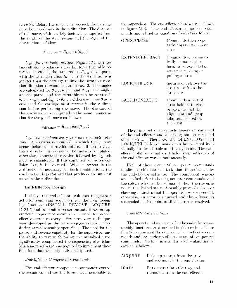
End-Effcctor Componcn, t Commands
The end-effector colnponent comnla,nds (:(mtrol
the actuators anti are the lowest level accessible to
the Slq)ervisor. The en(l-effector hardware is shown
in figure 5(t)). The en(t-efl_wt()r comt)()n('nt c()m-
man(is an(t a I)rM' ext)lanation of each task follow:
OPEN/CL()SE C()mmamts the re('('l)-tat'l(' fingers 1() Ol)('n or('lose
EXTEND/FIETRACT Commands a Imeumat -
ieally a('t ual e(l plal-form It, t)e ext('n(h'(t ()r
retract('(t trashing (>r
pulling a st rul
IX)CK/UNLOCK St,cures or releases th(,slrut t.()()r from lhe
st rll('l liFe
LATCII/UNLATCH (_()nlnlalldS a I)air ()fstI'lll hold(,rs t() oh)s(,
or open ar(mn(] lhe
alignment and gras I)
adapt ers lo('at ed onthe strut
There is a set of recei)tach' fingers on each end
of the end efDctor and a locking lltlt OI1 each cll(]
of the strut. Therefor(,, the ()I)EN/CL()SIq and
LOCK/UNLO('K c()mman(ts can t)(' ex(wuted in(ti-
vidually for the left si(h' anti the right side. The ('n(l-
effector t)latf{)rms anti strut hol(hws ()n l)olh ends ()fthe end (,ffe('tor work simultanc(msly.
Each of these elem('ntal ('()nit)orient ('on)lnan(ls
implies a self-contained task that is t)erfl)rnwd bythe en(t-cfl'('etor softwar('. Tim cOral)On(rot sensors
arc ehecke(| prior to issuing a('tuat()r (_()IlllIHtll(tS, all(t
tile softwaI'(' issues t}l(' Colnnmll(| wh(m the sta|us is
not in the (lesire(I state. Assembly l)roeee(ls if sensorchecking indicates (hal |lip ()t)(q'ali(m was suc(:essful;
otherwise, till error is returned and the software is
suspended at this poinl until the error is resolve(t.
End-Effrctor FuT_ctions
The el)era( i(ma.1 sequen('es f()r th(' en(l-(qfe(:tor as-
semI)ly functions are (h_s(Til)(,(t h) this set:lion. Tlwse
functions rei)resent the (tevic(,-hw(q end-ef[e('tor com-IllaIl(]S all(| are llla(te lip ()[ a s(,(tll(,iic(, of eOillpOll(,ilt
comman(ls. Th(" fmwtions and a brief explanation ofeach task follow:
ACQI_II{E
Dt_()P
l)ieks nit a strut front tlw trayatt(l retains it, in the end effe('t()r
Puts a strut into t,he tray andreleases it from the end effector
11
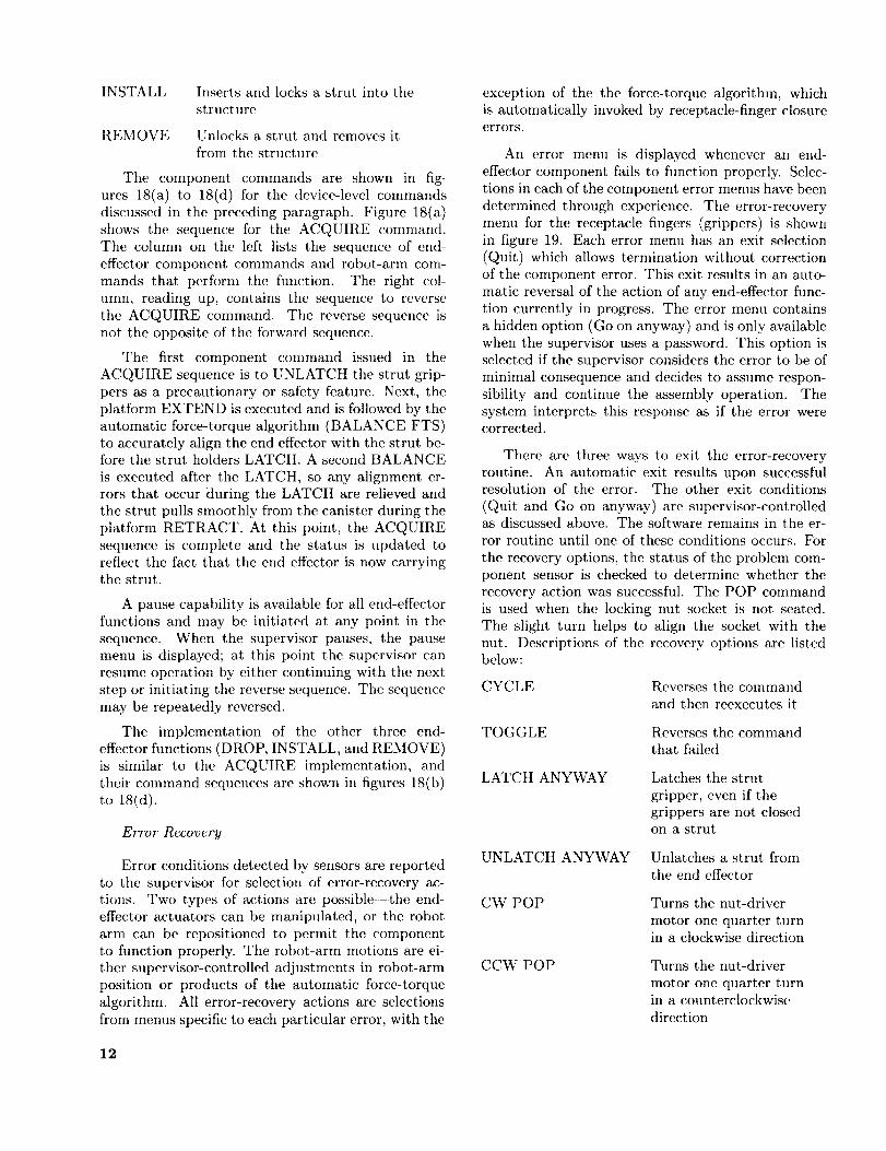
INSTALL Insertsandlocksa strut intothestructure
REMOVE Unlocksa strut andremovesitfromthestructure
The componentcommandsare shownin fig-ures18(a)to 18(d)for the device-levelcommandsdiscussedin the precedingparagraph.Figure18(a)showsthe sequencefor the ACQUIREcommand.The column oil the left lists the sequence of end-
effector component commands and robot-arm corn-
mands that perform the function. The right col-
umn, reading up, contains the sequence to reverse
the ACQUIRE command. The reverse sequence isnot the opposite of the forward sequence.
The first component command issued in the
ACQUIRE sequence is to UNLATCH the strut grip-
pers as a precautionary or safety feature. Next, the
platform EXTEND is executed and is followed by the
automatic force-torque algorithm (BALANCE FTS)to accurately align the end effcctor with the strut be-fore the strut holders LATCH. A second BALANCE
is executed after the LATCH, so any alignment er-rors that occur during the LATCH are relieved and
the strut pulls smoothly from the canister during the
platform RETRACT. At this point, the ACQUIRE
sequence is complete and the status is updated toreflect the fact that the end effector is now carryingthe strut.
A pause capability is available for all end-effector
functions and may be initiated at any point in the
sequence. When the supervisor pauses, the pausemenu is displayed; at this point the supervisor can
resume operation by either continuing with the next
step or initiating the reverse sequence. The sequence
may be repeatedly reversed.
The implementation of the other three end-
effector fimctions (DROP, INSTALL, and REMOVE)is similar to the ACQUIRE implementation, and
their command sequences are shown in figures 18(b)
to 18(d).
Error Recovery
Error conditions detected by sensors are reported
to the supervisor for selection of error-recovery ac-
tions. Two types of actions are possible--the end-effeetor actuators can be manipulated, or the robot
arm can be repositioned to permit the component
to function properly. The robot-arm motions are ei-ther supervisor-controlled adjustments in robot-arm
position or products of the automatic forcc-torque
algorithm. All error-recovery actions are selections
from menus specific to each particular error, with the
12
exception of the the force-torque algorithm, whichis automatically invoked by receptacle-finger closureerrors.
An error menu is displayed whenever an end-
effector component fails to function properly. Selec-tions in each of the component error menus have been
determined through experience. The error-recovery
menu for the receptacle fingers (grippers) is shown
in figure 19. Each error menu has an exit selection
(Quit) which allows ternfination without correctionof the component error. This exit results in an auto-
matic reversal of the action of any end-effector func-
tion currently in progress. The error menu contains
a hidden option (Go on anyway) and is only available
when the supervisor uses a password. This option isselected if the supervisor considers the error to be of
minimal consequence and decides to assume respon-
sibility and continue the assembly operation. The
system interprets this response as if the error werecorrected.
There are three ways to exit the error-recovery
routine. An automatic exit results upon successfulresolution of the error. The other exit conditions
(Quit and Go on anyway) are supervisor-controlledas discussed above. The software remains in the er-
ror routine until one of these conditions occurs. For
the recovery options, the status of the problem com-
ponent sensor is checked to determine whether the
recovery action was successflfl. The POP commandis used when the locking nut socket is not seated.
The slight turn helps to align the socket with the
nut. Descriptions of the recovery options are listedbelow:
CYCLE
TOGGLE
LATCH ANYWAY
UNLATCH ANYVCAY
CW POP
CCW POP
Reverses the command
and then reexecutes it
Reverses the command
that failed
Latches the strut
gripper, even if thegrippers are not closedon a strut
Unlatches a strut from
the end effector
Turns the nut-driver
motor one quarter turnin a clockwise direction
Turns the nut-driver
motor one quarter turnin a counterclockwise
direction

DITHERARM
BALANCE FTS
ADJUST
Moves tile robot arm
through small cyclic
motions in a particular
direction in an attemptto jar loose a stuck
component
Reduces the loads on a
colnponent by slightly
repositioning tile robot,arnl
Manual repositioning
of tile robot arm by
tile supervisor
Data Content and Modification
The assembly system conditions are stored in a
shared data base, which contains two basic typesof information the current status of all elements
of the assembly system and structure, and the pre-determined positions that are used to direct and con-trol the robot arm and motion bases. The current
status information is inaintained continuously to rep-
resent the physical state of the system at. any point
in time and to thus ensure continuity of system oper-
ations. The status is updated automatically duringtest runs. The predetermined position informationfor the robot arm and motion base includes loca-
tions and orientations that are associated with the
installation of individual struts. The predetermined
position information also describes the collision-free
paths that the robot arm and motion base follow be-
tween the canister and the various installation posi-tions in the truss.
Data Description
Figure 20 illustrates the data section that is bro-
ken down into tile following elements: motion-hawse
position, strut type, robot-arnl status, tray status,
tray handle locations, current strut status, currentmotion-base position, and end-effector status.
The MOTION_BASE_POSITION record stores
the x, y, and 0 values (X_Car, YCar, and Turntable)for the predetermined motion-base locations that
establish the positioning relationship between the
robot arm and the truss. There are 70 unique
motion-base positions for the 102-member truss. In
an attempt to minimize motion-base moves, manystruts are installed with the motion base situated at
the same position. Also, the 120 ° rotational symme-
try of the structure allows the x and y carriage po-sitions to be repeated for comparable struts at threelocations around the structure.
The STRUT_TYPE record contains all the data
necessary to describe the installation and storageconditions for each of the 102 strut members. Each
strut is identified and accessed by a unique alpha-
numeric designation (Name). The current locationof the strut (Where) is accessed by the system before
ally strut operation can be initiated. The system
nmst know if the strut is currently in its tray, in-
stalled in the structure, or held by the end effector.
When a strut is selected for installation, the system
refers to a list of struts (Connect_To), which definesthose struts that must be installed in the truss priorto installation of the selected strut. This check is a
safety feature to ensure that the required initial con-ditions for installation of the selected member are
satisfied. The secondary reference to tile location
status (Where) of each strut on this list certifies thatall required struts are installed. The installation po-
sition (Loc In Cell) identifies which of the 19 pre-
determined paths is to be followed to install or re-
nlove a strut. The end of a strut with a preattached
node (Node_End) indicates which nut driver on theend effector nmst not be operated while installing the
strut. If the end effcetor nmst capture another node,
the end to be captured is specified (CapEnd). Tile
end condition of the installed strut (Cantilew_r) is
used to establish predefined modifications t.o tile pathwhich must occur during the capture sequence. Be-
cause of tray packing limitations, a preattached node
may not be located on the correct end associated
with a direct path entry. This condition is identified(Flip) and initiates a robot-arm comnland to rotate
the strut 180 ° at the transition point in the strut in-
stallation path. The assigned tray and slot positions
(Tray, Slot) are required to replace or insert a strut
in the tray. Each state in the predefined path definesthe robot-arm positions (State Pos). The collision-
avoidance algorithm requires that the end position
of the core struts (X_End, Y End) be defined forcomputation of potential collision conditions.
The ROBOT_STATUS record contains the cur-
rent positioning point for all strut paths (State,
Cond State). The current strut in the robotarm (Strut Now), the strut in the canister to be
retrieved (Strut_Getting_Now), or the last strut
that was installed or removed by the robot arm
(Strut_JustHad) arc represented in this record.
The TRAY_STATUS record maintains all infor-
mation pertaining to the strut storage trays. The
path-state identifier (Tray_State) and the objective
of the move (TrayMode) are used to store or retrieve
a tray. The number of tile tray (Current_Tray) thatstruts are being removed from or stored in is also
maintained. The approach points to the working
13
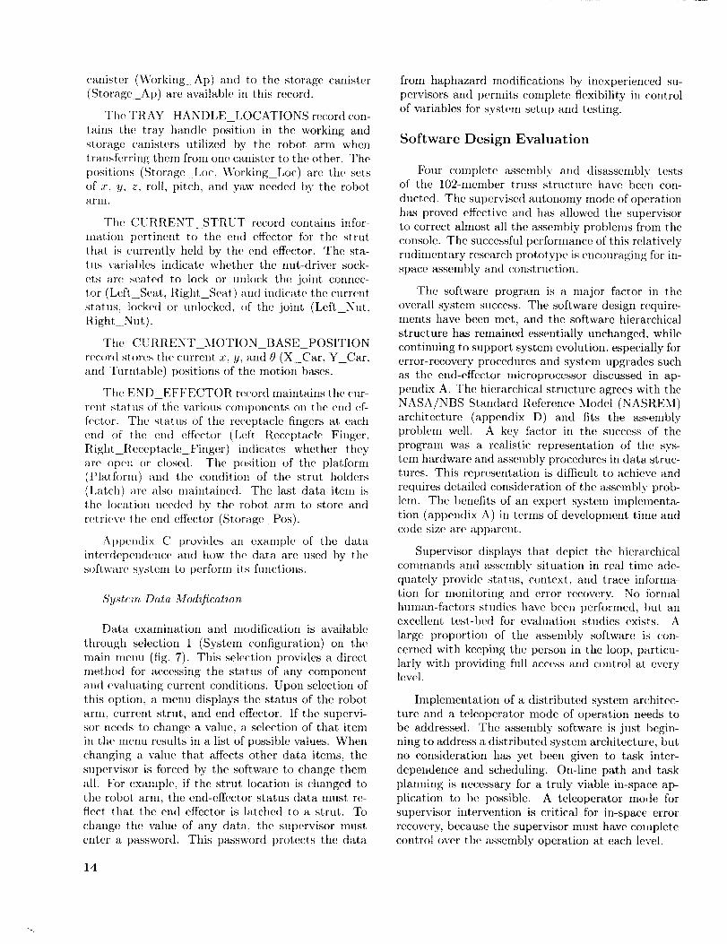
canister(Working Ap) andto the storagecanister(Storage_Ap)areavailablein thisrecord.
TheTRAY_HANDLE_LOCATIONSrecordcon-rains the tray handlepositionin the workingandstoragecanistersutilized by the robot ann whentransf(_rringthemfromone,canisterto theother.Thepositions(StorageLoc,Working_Lot)arethesetsof x, y, z, roll, pitch, and "_'aw needed by the robotarnl.
The (LRRENT STRUT record contains infor-
mation pertinent to the end effeetor for the strut
that is currently held by t.tH, end effeetor. The sta-tus variables indicate whether the nut-driver sock-
ets are seated to lock or unlock the joint connec-
tor (Left Seat, Right_Seat) and indicate the currentstatus, locked or unlocked of the joint (Left_Nut,
Flight_Nut).
The CURRENT_MOTION_BASE_POSITION
record slores the current x, y, and0(X Car, Y_Car,
and Turntable) positions of the motion bases.
The END EFFECTOR record maintains the cur-
rent status of tt]e various components on the end ef-
f(,ctor. The status of the receptacle fingers at. each
end of the end effector (Left Receptacle Finger,Right_Receptacle Finger) indicates whether they
are open or closed. The position of the platform(Platform) and the condition of the strut holders
(Latch) are also maintained. The last data item is
the location needed by the robot arm to store and
retrieve the end effector (Storage Pos).
Apt)endix C provides an examt)le of the data
interdepend(mc(_ and how t h(_ data are used by the
software system to t)erform its functions.
Sy,st_:m Data Modificatiou
Data examination and modification is available
through selection 1 (System configuration) on the
main metal (fig. 7). This selection provides a direct
method for accessing the status of any componentand evaluating current conditions. Upon selection of
this option, a menu displays the status of the robot
arm, current strut, and end effeetor. If the supervi-
sor needs to change a value, a selection of that itemin the menu results in a list of possible values. When
changing a value that affects other data items, the
supervisor is forced by the software to change them
all. t_br exmnple, if the strut location is changed tothe robot arm, the end-effector status data must re-flect that the end effeetor is latched to a strut. To
change the value of any data, the supervisor must
enter a password. This password protects the data
14
from haphazard modifications by inexperienced su-pervisors and permits complete flexibility in control
of variables for system setut) and testing.
Software Design Evaluation
Four complete assembly and disassembly testsof the 102-member truss structure have been con-
ducted. The supervised autonomy mode of operation
has proved effective and has allowed the supervisor
to correct almost all the assembly problems from the
console. The successflfl performance of this relativelyrudimentary research prototype is encouraging for in-
space asseml)ly and construction.
The software program is a major factor in the
overall system success. The software design require-ments have been met, and the software hierarchical
structure has remained essentially unchanged, while
continuing to support system evolution, especially for
error-recovery procedures and system upgrades suchas the end-effector microprocessor discussed in ap-
pendix A. The hierarchical structure agrees with the
NASA/NBS Standard Reference Model (NASREM)
architecture (appendix D) and fits the assemblyproblem well. A key factor in the success of the
program was a realistic representation of the sys-
tem hardware and assembly procedures in data struc-tures. This representation is difficult, to achieve and
requires detailed consideration of the assembly prob-
lem. The benefits of an expert systein implementa-
tion (appendix A) in tertns of development time andcode size are apparei_t.
Supervisor displays that depict the hierarchical
commands and assembly situation in real time ade-
quately provide status, context, and trace informa-tion for monitoring and error recovery. No formal
human-factors studies have been performed, but anexcellent test-bed for evaluation studies exists. A
large proportion of the assembly software ix con-cerned with keeping the person in the loop, particu-
larly with providing full access and control at everylevel.
Implementation of a distributed system architec-ture and a teleoperator mode of operation needs to
be addressed. The assembly software is just. begin-
ning to address a distributed system architectm e, butno consideration has yet been given to task inter-
dependence and scheduling. On-line path and task
planning is necessary for a truly viable in-space ap-
plication to be possible. A teleoperator mode for
supervisor intervention is critical for in-space error
recovery, because the supervisor must have completecontrol over the assembly operation at. each level.
Concluding Remarks
An initial versionof anautomatedassemblysys-tem for trussstructureshasbeendevelopedandiscurrentlyoperational.Experiencegainedduringtheassemblyand disassemblyof a 102-membertetra-hedraltrussdemonstratessuccessfulperformanceoftheautomatedsystemandof thesupervisorinterfaceusedfor monitoringandintervention.Basedon thisexperience,the softwaredesign,hierarchicalstruc-ture,andinternaldata representationdescribedaretypicalof whatisrequiredforautomatedoperationsandshowpromisefor usein projectedin-spaceas-semblyandconstructionprojects.Thesoftwarere-quirementsanddesignserveasa model,aswellasa test-bed,for thedevelopmentof softwarerequiredby moresophisticatedautomatedsystems.
Thesoftwaredesignprocessemphasizedthe im-portanceof definingthe interfacerequirementsand
theroleof thesupervisor.Theinterfacebetweentheautomatedsystemandthesupervisorprovidesacon-cisemethodof displayingpossiblecommandselec-tions,accessto all devicelevels,andcurrentsystemtaskexecutionandstatus.Thesupervised-autonomymodeofoperationmakessystemsupervisionfromre-motesites,suchasthe ground,feasible.This modeofoperationminimizesthedemaudfor limitedastro-nautresources.
Hardwaretestexperienceidentifiedunanticipatedbut critical automatedsysten_capabilities,suchastheneedto pauseandreversetheassemblyprocess.The testingalsounderscoredthe valueof a well-informedsupervisorin anyautomatedoperation.
NASALangleyResearchCenterHampton,VA23665-5225May19,1992
15

Appendix A
Implementation
Theassemblysystemis managedby severaldig-ital computersthat areseriallyconnectedthroughRS-232communicationlines. The a(tministration,assembly,anddevicelevels(fig.6),andtheoperatorinterfacefunctionsresideona minicomputerandareimplementedin FORTRAN.Component-levelfunc-tions resideon auxiliarycomputers.Thesoftwaredesignwasdevelopedindependentlyof a computerhardwareconfigurationandhasbeenrunona nun>berofdifferentcomputerarrangements.All commu-nicationsarepassedthroughtheminicomputer,eventhoughfunctionallythey might be issueddirectlyfromonemachineto another.Thedatapassedbe-tweenprocessorsarewritten in ASCII format.Thishuman-readableformatallowsstand-alonecheckoutto beperformedonsimpleternfinals.
The motionbaseis controlledby a commercialindexerboardhostedon an Intel 80286basedpro-cessor.Commands to this processor are generated
by a BASIC program that serves only as a transla-tor for the positioning commands. All the collision-avoidance calculations are performed in real time on
the minicomputer.
TILe robot-arm motions and end-effector compo-
nent commands are controlled by a BASIC program
on a 68000 processor. The robot-arm processor stores
data locally (all the z, 9, z, roll, pitch, and yaw po-
sitions) and describes the operational position defi-nitions and paths used for the assembly operations.This local data storage minimizes the amount of in-
formation passed between the processors.
Two major changes have been made to the ini-
tim iinplementation a software language substitu-tion and a computer hardware addition. As a re-sult of the modularity of the design, the upgrades
were easily performed. The software change entailed
the development of the robot-arm, path-state logic as
an expert system; this system replaced the originalFORTRAN implementation. The computer upgradethat was initiated involved moving the device and
component level for the new end effector to a micro-
processor. The device level of tile current end effec-tor resides on the minicomputer, and the component
level resides on the robot-arm processor. Both these
upgrades are discussed in more detail in the followingsections.
Expert System Implementation
Traditional programining languages such as FOR-TRAN and BASIC are not well suited for encapsu-
lating the knowledge required for complex assemblysequences. Preliminary investigations into the appli-
cation of expert system technologies to perform the
decision-nmking portions of the software system have
been very encouraging.
The Knowledge Engineering System (KES) ex-
pert system development tool was utilized in this
implementation (ref. 12). Rule-based, backward-chaining techniques are applied to accomplish the de-
cision making or inferencing. A set of antecedent/
consequence (if/then) rules have been fornmlated
which capture knowledge pertaining to the path se-lection for strut assembly and disassembly. These
rules, along with attributes and procedures, are con-tained in a file known as the knowledge base. Back-
ward chaining (goal-directed infexencing) applies de-ductive reasoning to the specified rules, whereby
a given conclusion follows directly from a known
premise.
The path from the grasp-point canister
(GP_CAN) to the grasp-point (GP) is decomposedinto a nulnber of individual states. (See fig. 12.) The
current location of the strut, the current location of
the robot arm, the type of strut being manipulated,
and the task specified by the automated system or
the supervisor (via menu selection) are all factors indetermining the sequence of states that make up the
robot-arm path. Rules haw_ been developed to im-
plement the state logic shown in figure 12. Theserules determine the direction of the robot-arm mo-
tion and any necessary conditional states betweenAP and GP. The direction of robot-arm motion is
determined from the current location of the robot
arm, the current status of the strut, and the task or
target state entered by the supervisor. Conditionalstate rules are invoked when performing node capture
operations between AP and GP and are primarily de-pendent upon strut cantilever conditions. Figure 21
contains examples of conditional state rules. Once amove has been determined, forward infcrcncing is ini-
tiated to build the command string, which is sent to
the robot arm. The KES forward inferencing uses
event-driven procedural techniques that, like con-
ventional programming languages, were structured
sequentially.
This expert-system tool provides an embedding
technique for integrating expert systems with proce-dural language code. The procedural code is able
to send, receive, and modify data from a knowledge
base through the use of run-time functions and spe-
cial data types. The embedding technique giw_s the
automated assembly system access to expert-system
techniques for decision making, but it leaves the ex-
isting operator interface intact. An expert-system
16
solutionto thepathdeterminationportionof theal-gorithmwasincorporatedwith little difficultybyuti-lizingtheexistingmenustructuresandinput/output(I/O) handlingcapabilities.
Theconciserepresentationaffordedby'tile rule-basedexpertsystemreducedthe linesof codesig-nificantlyand increasedthe maintainabilityof thesoftware. Approximately850 linesof FORTRANcodewerecondensedinto 20simplifiedKESrules.Evenduring the early stagesof the development,modificationsandupgradeswereperformedrapidly'.The successof the expert-systemimplementationhaspromptedthe applicationof thesetechniquesto othermodulesof the assembly-systemsoftware,suchastray handling,errorhandling,andcollisionavoidance.
End-EffeetorMicroprocessorImplementation
All end-effectorfunctionsfor tile newendeffec-tor arenowimplementedonamicroprocessor.Thisend-effectorsoftwarelogicisimplementedin the "C"programminglanguageonaSiemensSAB80535mi-croprocessor.The developmentsystemselectedisANSI C compatibleand includeslanguageexten-sionsthat provideaccessto all processor-dependent
features.The SAB 80535microprocessorsupportsanalog-to-digitalconversionandbit I/O. The soft-wareisresponsibleforbothsequencecontrolandsen-sormonitoringfor all end-effectoroperations.Thesoftwaremaintainslocaldatathat describethe sta-tusoftheend-effectorandsensorcomponentsonthemicroprocessor.
The end-effectormicroprocessorimplementsthedeviceand componentlevelsof the assemblysoft-ware. It decomposesthe assenfl)ly-orienteddevicecommands(INSTALL,REMOVE,ACQUIRE,andDROP)intocomponentcommandsandmonitorsthesensors.The microprocessorintegratedeasilyintothe automatedassemblysystemas a result of thedesignhierarchyandmodularity.By standardizingthesefunctions,multipleendeffectorscanbeaccom-modatedthat performsimilarfunctions,suchastheINSTALL,ondifferententities.Thus,endeffectorsthat install strutsandpanelsall look the sametotile automatedassemblysystem. Theend effectoronthemicroprocessortakesadvantageof theexperi-encegainedin thebaselineautomatedassemblyop-erations.Reference13containsadditionaldetailsontile end-effectormicroprocessorimplementationandsoftware.
17
Appendix B
Glossary
actuator
backward-chaininginferencing
component
embedding
expertsystem
knowledgebase
knowledge-basedexpertsystem
RS-232communicationline
rule-basedexpertsystem
degreesof free(toni
supervisedautonomy
top-downdesign
devicethat appliesforceto movea mechanisln
goal-directedapproachof decisionmaking;thepursuitof agoalmayrequiretiledeterminationof substates,whichthemselvesmayrequireasubgoalsolution
anyoneof theend-effectorhardwaremechanisms
combiningconventionalprogrammingapplicationswith anexpertsystemto forma singleexecutableprogram
a computerprogramthat usesknowledgeandreasoningtechniquestosolveproblemsthat normallyrequiretheservicesof atrumanexpert
filethat containsthefactsandheuristicsthat representhumanexpertiseabouta specificdomain
subsetof thegeneralareaof expertsystemsin whichanexpert'sknowledgeabouta classof problemsis maintainedin onefile (knowl-edgebase);a separatereasoningmechanismoperatesonthis knowl-edgeto producea solution
a communicationsprotocolfortransmittinginformationbetweentwocomputersin aserialmode(onebit at a time)
systemthat usesantecedent/consequence(if/then) constructstorepresentknowledge
numberof independentpositionvariablesthat wouldhaveto bespecifiedto locateall partsof a mechanisin
a modeof systemoperationin whichoperatorattentionor interven-tion isrequiredonlywhena problemhasoccurredthat cannotbecorrectedby theautomatedsystem
a methodologythat beginsby layingout anoverallprogramstructureandsuccessivelydefininglowerlevelsin increasingdetail
18

Appendix C
Example of Data Accesses and Modifications
The followingexampleshowshowthe datadefinedin figure20areactuallyreferencedandusedby thesoftware.Theactualmenuitemsfromfigure7 are shown ill bold. Only the forward execution of tile coinmand
stream is shown. No pause or reverse sequences are included. To keep the example as simple as possible, it
is assumed that everything passes the appropriate tests necessary to contilme execution. The strut in this
example is of the direct installation case type.
Conllnands
FETCH AND CONNECT:
Input strut name to fetch
Check data to verify" valid name
Veri_' necessary struts installed
Update data
FETCH:
Verify no strut currently in robot arm
Veri_' strut location
Check access to tray; do one of the following:
1) Current tray contains strut
2) Next tray contains strut
ROBOT: (Move tray to storage)MOVE TRAYS:
TO STORAGE:
TRAY APPROACH POINT
Verify current stateMove robot arm
Update dataTRAY POINT
Verify current state
Move robot arm
Update data
Pick up tray
Similar to ACQUIRE
Update data
TRAY APPROACH POINT
Verify current state
Move robot arm
Update dataSTORAGE APPROACH POINT
Verify current stateMove robot arm
Update data
STORAGE POINT
Verify current stateMove robot arm
Update data
Data accessed
STRUT_TYPE.NameSTRUT TYPE.Connect To
ROBOT_STATUS.Getting_Now = Strutname
ROBOT_STATUS.Strut_Now = NONE
STRUT_TYPE.Where = CANISTER,
STRUT TYPE.Tray =
TRAY_STATUS .Current_Tray
STRUT_TYPE.Tray >
TRAY STATUS.Current_Tray
TRAY_STATUS.Tray_Mode = STORING
TRAY_STATUS .Tray_State
TRAY_STATUS.Tray_Ap
TRAY_STATUS.Tray_State = TRAY_AP
TR AY_STATU S.Tray_St ate
TRAY_HANDLE_LOCATIONS.Working_Loc
TRAY_STATUS.Tray_State = TRAY
TRAY_STATUS.Current_Tray decremented by 1
TRAY_STATUS .Tray_State
TRAY_STATU S. Tray_A p
TRAY_STATUS.Tray_State = TRAY_AP
TRAY_STATUS .Tray_State
TRAY STATUS.Storage_Ap
TRAY_STATUS.Tray_State = STORAGE_AP
TRAY STATUS.Tray_State = STORAGE_AP
TRAY_HANDLE_LOCATIONS.Storage_Loc
TRAY_STATUS.Tray_State = STOR
19
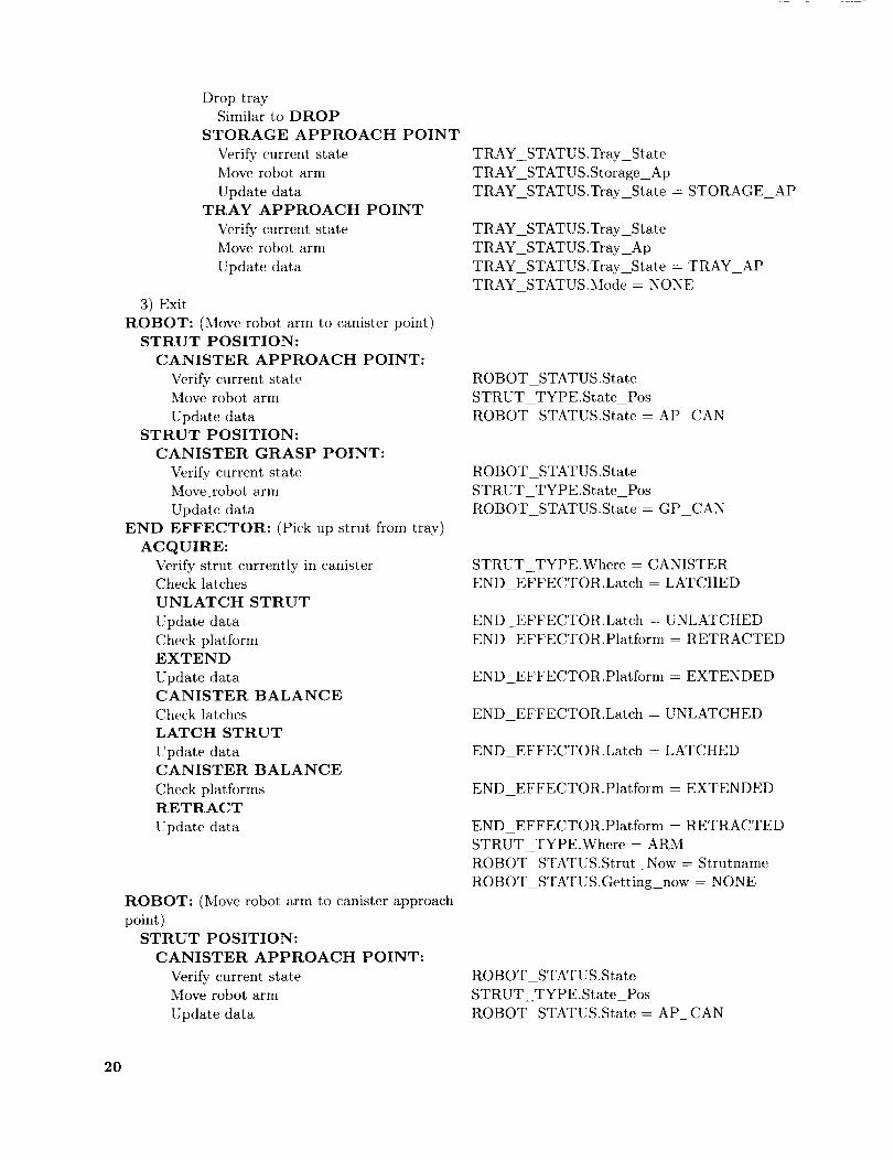
DroptraySimilarto DROP
STORAGE APPROACH POINTVeri_ currentstateMoverobotarmUpdatedata
TRAY APPROACH POINTVerifycurrentstateMoverobotarmUpdatedata
3)ExitROBOT: (),loverobotarmto canisterpoint)
STRUT POSITION:CANISTER APPROACH POINT:
VerifycurrentstateMoverobotarmUpdatedata
STRUT POSITION:CANISTER GRASP POINT:
VerifycurrentstateMove.robotarmUpdatedata
END EFFECTOR: (Pickupstrut fromtray)ACQUIRE:
Verify strutcurrently in canister
Check latches
UNLATCH STRUT
Update data
Check platform
EXTEND
Update data
CANISTER BALANCE
Check latches
LATCH STRUT
Update data
CANISTER BALANCE
Check platforms
RETRACT
Update data
ROBOT: (Move robot arm to canister approach
point)STRUT POSITION:
CANISTER APPROACH POINT:
Verify current stateMove robot arm
Update data
TRAY_STATUS .Tray_State
TRAY_STATUS.Storage_Ap
TRAY_STATUS.Tray_State -- STORAGE_AP
TRAY_STATUS .Tray_State
TRAY_STATUS.Tray_Ap
TRAY_STATUS.Tray_State = TRAY_AP
TRAY_STATUS.Mode = NONE
ROBOT_STATUS.State
STRUT_TYPE.State_Pos
ROBOT_STATUS.State = AP_CAN
ROBOT_STATUS .State
STRUT_TYPE.State_PosROBOT STATUS.State = GP CAN
STRUT TYPE.Where = CANISTER
END EFFECTOR.Latch = LATCHED
END_EFFECTOR.Latch = UNLATCHEDEND EFFECTOR.Platform = RETRACTED
END_EFFECTOR.Platform = EXTENDED
END EFFECTOR.Latch = UNLATCHED
END_EFFECTOR.Latch = LATCHED
END EFFECTOR.Platform = EXTENDED
END EFFECTOR.Platform = RETRACTED
STRUT TYPE.Where = ARM
ROBOT_STATUS.Strut_Now = Strutname
ROBOT_STATUS.Getting_now = NONE
ROBOT_STATUS .State
STRUT TYPE.State_Pos
ROBOT_STATUS.State = AP CAN
20
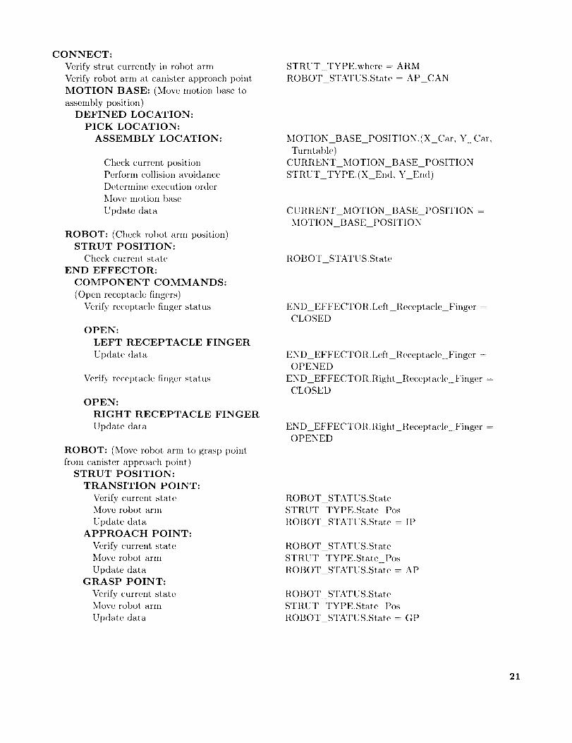
CONNECT:Verifystrut currentlyin robotarmVerifyrobotarmat canister approach point
MOTION BASE: (Move motion base to
assembly position)
DEFINED LOCATION:
PICK LOCATION:
ASSEMBLY LOCATION:
Check current positionPerform collision avoidance
Determine execution order
Move motion base
Update data
ROBOT: (Cheek robot arm position)STRUT POSITION:
Check current state
END EFFECTOR:
COMPONENT COMMANDS:
(()pen receptaele fingers)
Veri_, receptacle finger status
OPEN:
LEFT RECEPTACLE FINGER
Update data
Verify reeet)taele finger status
OPEN:
RIGHT RECEPTACLE FINGER
Update data
ROBOT: (Move robot arm to grasp point
from canister approach point)STRUT POSITION:
TRANSITION POINT:
Verify current state
Move robot arm
Update dataAPPROACH POINT:
Verify current state
Move robot arm
Update dataGRASP POINT:
Verify, current state
Move robot, arm
Update data
STRUT_TYPE.where = ARM
ROBOT_STATUS.State = AP_CAN
MOTION_BASE_POSITION.(X_Car, Y Car,
Turntable)
CURRENT_MOTION_BASE_POSITION
STRUT TYPE.(X_End, Y_End)
CURRENT MOTION BASE POSITION =
MOTION_BASE POSITION
ROBOT_STATUS.State
END_EFFECTOR.Left_Receptacle_Finger =CLOSED
END_EFFECTOR.Left_Receptacle_Finger =OPENED
END_EFFECTOR.Right_Receptacle_Finger =
CLOSED
END_EFFECTOR.Right_Recet)tacle Finger =OPENED
ROBOT_STATUS. State
STRUT TYPE.State Pos
ROBOT STATUS.State IP
ROBOT_STATUS .State
STRUT_TYPE.Stat, e_Pos
ROBOT_STATUS.State = AP
ROBOT STATUS.State
STRUT TYPE.State Pos
ROBOT STATUS.State = GP
21
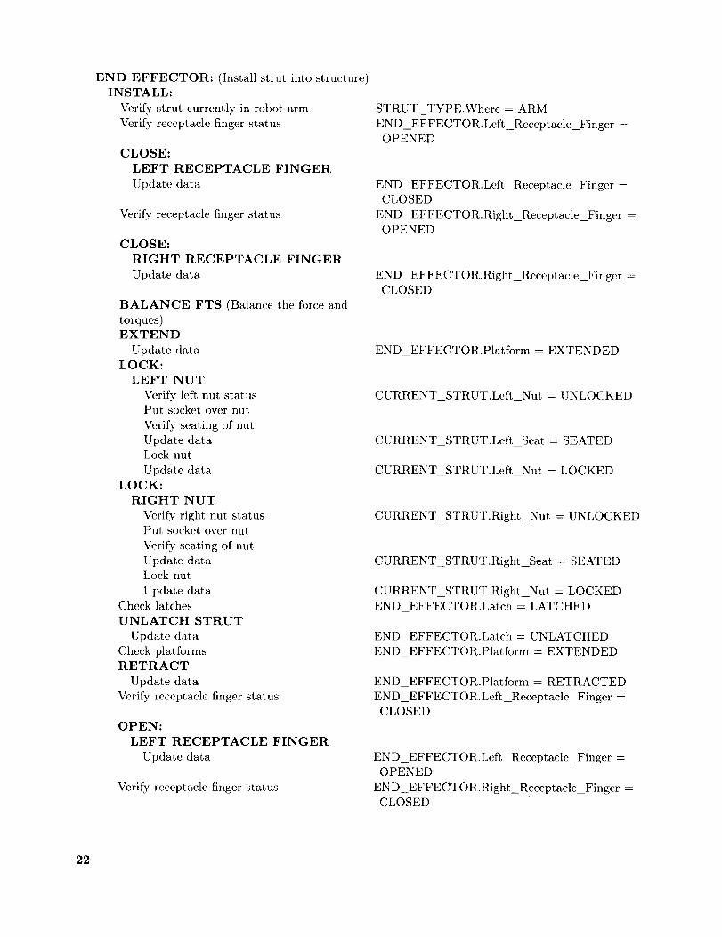
END EFFECTOR: (Installstrut intostructure)INSTALL:
Verifystrut currentlyin robotarmVerifyreceptaclefingerstatus
CLOSE:LEFT RECEPTACLE FINGERUpdatedata
Verifyreceptaclefingerstatus
CLOSE:RIGHT RECEPTACLE FINGERUpdatedata
BALANCE FTS (Balancetheforceandtorques)EXTEND
UpdatedataLOCK:
LEFT NUTVeri.fyleft nutstatusPut socketovernutVerifyseatingof nutUpdatedataLocknutUpdatedata
LOCK:RIGHT NUT
Verifyrightnut statusPut socketovernutVerifyseatingof nutUpdatedataLocknutUpdatedata
ChecklatchesUNLATCH STRUT
UpdatedataCheckplatformsRETRACT
UpdatedataVerifyreceptaclefingerstatus
OPEN:LEFT RECEPTACLE FINGER
Update data
Verify receptacle finger status
STRUT_TYPE.Where = ARM
END_EFFECTOR.Left_Receptacle_Finger =OPENED
END_EFFECTOR.Leff_Receptacle_Finger=CLOSED
END_EFFECTOR.Right_Receptacle_Finger=
OPENED
END_EFFECTOR.Right_Receptacle_Fingcr =CLOSED
END_EFFECTOR.Platform = EXTENDED
CURRENT_STRUT.Left_Nut = UNLOCKED
CURRENT_STRUT.Left_Seat = SEATED
CURRENT STRUT.Left Nut = LOCKED
CURRENT_STRUT.Right_Nut = UNLOCKED
CURRENT STRUT.Right Seat = SEATED
CURRENT_STRUT.RightNut = LOCKED
END_EFFECTOR.Latch = LATCHED
END_EFFECTOR.Latch = UNLATCHED
END_EFFECTOR.Platform = EXTENDED
END_EFFECTOR.Platform = RETRACTED
END EFFECTOR.Left_Recept acle_Finger =CLOSED
END_EFFECTOR.Left_Receptacle Finger =OPENED
END_EFFECTOR.RightReceptacle_Finger =CLOSED
22
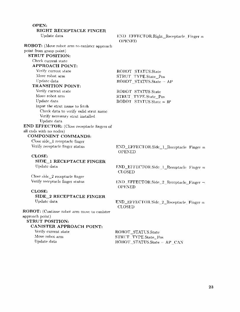
OPEN:RIGHT RECEPTACLE FINGER
Updatedata
ROBOT: (Moverobotarmto canisterapproachpoint fromgrasppoint)
STRUT POSITION:Check current state
APPROACH POINT:
Veri_' current stateMove robot arm
Update data
TRANSITION POINT:
Verify current stateMove robot arm
Update data
Input the strut name to fetch
Check data to verify valid strut name
Verify necessary strut, installed
Update data
END EFFECTOR: (Close receptacle fingers of
all ends with no nodes)COMPONENT COMMANDS:
Close side_l receptacle finger
Verify receptacle finger status
CLOSE:
SIDE 1 RECEPTACLE FINGER
Update data
Close side_2 receptacle finger
Verify receptacle finger status
CLOSE:
SIDE 2 RECEPTACLE FINGER
Update data
ROBOT: (Contimm robot, arm move to canister
approach point)STRUT POSITION:
CANISTER APPROACH POINT:
Verify current stateMove robot arm
Update data
END_EFFECTOR.Right_Receptacle_Finger --OPENED
ROBOT_STATUS.State
STRUT_TYPE.State_Pos
ROBOT_STATUS.State = AP
ROBOT_STATUS .State
STRUT_TYPE.State_PosROBOT STATUS.State = IP
END_EFFECTOR.Side 1 Receptacle_Finger =OPENED
END_EFFECTOR.Side 1 ReceptacleFinger =CLOSED
END_EFFECTOR.Side 2 ReceptacleFinger =OPENED
END_EFFECTOR.Side 2 ReceptacleFinger =CLOSED
ROBOT_STATUS.State
STRUT_TYPE.State_Pos
ROBOT STATUS.State= AP CAN
23
Appendix D
Comparison With NASREM
Althoughthe automated-assemblysystemsoft-wareis developedfrom the systemrequirements,theresultingprogramstructurecloselyresemblestheNASA/NBSStandardReferenceModel(NASREM)architecture(ref. 14). The NASREM architec-ture is depicted in figure 22, and the correspond-
ing automated-assembly software structure is shown
in figure 23. The automated-assembly hierarchy
corresponds to the four lowest levels of NASREM.
For example, the NASREM primitive level can becompared with the automated-assembly device level,which includes the robot arm, the end effector, and
the motion base. (See fig. 6.) The NASREMelement-move level corresponds to the assembly level
in the automated-assembly hierarchy. Figure 23 in-
cludes only those functions at each level that are
needed in the automated-assembly application. Typ-ical supervisor commands at each level and error-
recovery actions are included for completeness.
Hardware actions and sensor processing occur at
the component (NASREM servo) level. Error con-
ditions are resolved by either supervisor intervention
or automated actions at the component level. Un-resolved errors are passed back through the hierar-
chy, and an automatic reverse of the tasks performed
at each level is initiated. For the assembly task, al-
ternative actions, which take the form of substituting
other struts for failed members, are available only, atthe administrative level. A use of alternate struts
requires replanning the assembly sequence.
Aside from the component level, the only other
testing is performed at the assembly level. Thesetests involve physically exercising the locking nut im-
mediately after a strut is picked up from the canisterto insure that it can be installed. Another test is
performed immediately after locking a strut into the
structure by attempting to retract the platform be-fore unlatching in order to verify the integrity of the
joint lock. A failure of either of these tests wouldresult in the selection of an alternate strut.
The world model information base is updated
at two levels the device level and the assemblylevel. At the device level, the end-effector status
model is updated at the successful completion of
each component action. At the assembly level, thetruss-structure model and the storage-canister status
are updated with the installation or removal of eachstrut.
The NASREM architecture provides good con-
ceptual agreement with the automated-assembly ap-
plication, although not all activities have an entry' atevery level. The hierarchical model does provide a
particularly concise display for supervisor visualiza-
tion. The hierarchical structure is capable of sup-
porting several assembly operations by providing astandard interface between the levels.
24

References
1. Heard, Walter L., Jr.; Bush, Harold G.; Wallsom,
Richard E.; and Jensen, J. Kcrmit: A Mobile Work Sta-
tion Concept for MechanieaUy Aided Astronaut Assembly
of Large Space Trusses. NASA TP-2108, 1983.
2. Dorsey, John T.; and Mikulas, Martin M., Jr.: Prelim-
inary Design of a Large Tetrahedral Truss/Hexagonal
Panel Aerobrake Structural System. AIAA-90-1050,
Apr. 1990.
3. Heard, Walter L., ,Jr.; Watson, Judith J.; Russ, Jerry L.;
Spring, Sherwood C.; and Cleave, Mary L.: Results of the
ACCESS Space Construction Shuttle Flight Experiment.
A Collection of Technical Papers AIAA Space Systems
Technology Conference, American Inst. of Aeronautics
and Astronautics, June 1986, pp. 118 125. (Available as
AIAA-86-1186.)
4. Bush, Harold G.; Herstrom, Catherine L.; Heard,
Walter L., .lr.; Collins, Timothy J.; Fichter, W. B.;
Wallsom, Richard E.; and Phelps, James E.: Design and
Fabrication of an Erectable Truss for Precision Segmented
Reflector Application. ,1. Spaeeer. _ Rockets, vol. 28,
no. 2, Mar. Apr. 1991, pp. 251 257.
5. Space Station Freedom External Maintenance Task Team
Final Report Volume I, Part 1. NASA Lyndon B.
Johnson Space Center, July 1990.
6. Space Station Freedom External Maintenance Task Team
Final Report Volurrtc I, Part 2. NASA Lyndon B.
Johnson Space Center, July 1990.
7. Space Station Freedom External Maintenance Task Tean_
Final Report Volume II, Part 1. NASA Lyndon B.
Johnson Space Center, July 1990.
9.
10.
11.
12.
13.
14.
Space Station Freedom External Maintenance Task Team
Final Report Volume II, Part 2. NASA Lyndon B.
Johnson Space Center, July 1990.
Rhodes, Marvin D.; Will, Ralph W.; and Wise. Marion A.:
A Telerobotic System for Automated Assembly of Large
Space Structures. NASA TM-101518, 1989.
Rhodes, Marvin D.; and Will, Ralph W.: Automated As-
sembly of Large Space Structures. IAF Paper No. 90-272,
Oct. 1990.
Will, Ralph W.; and Rhodes, Marvin D.: An Automated
Assembly System for Large Space Structures. Cooperative
Intelligent Robotics in Space, Rui J. deFigueircdo and
William E. Stoney, eds., Volume 1387 of Proceedings of
SPIE The International Society for Optical Engineering,
Soc. of Photo-Optical Instrumentation Engineers, 1990,
pp. 60 71.
Knowledge Base Author's Manual KES PS. Software
Architecture & Engineering, Inc., c.1990.
Doggett, William R.; Rhodes, Marvin D.; Wise,
Marion A.; and Armistead, Maurice F.: A Smart End-
Effector for Assembly of Space Truss Structures. Paper
presented at SOAR 91 Fifth Annual Space Operations,
Applications, and Research Symposium, Final Program
(Houston, Texas), July 9 11, 1991.
Atbus, James S.; McCain, Harry G.; and Lumia, Ronald:
NASA/NBS Standard Reference Model for Telerobot Con-
trol System Architecture (NASREM). NBS Tech.
Note 1235, U.S. Dep. of Commerce, July 1987.
25

(a) Proposed astronomical observatory.
L-92-25
L-90-4776
(b) Concept for a Mars transfer vehicle and aerobrakc.
Figure 1. Artist's conception of future space missions.
26

Robot arm End effector
Trays withStorage canister_ __ .
_ _v_7__-truss struts
Truss __--_--_____/Working canister
Y-motion base
O _'_ X-motion base
Rotating-motion base
(a,) Schematic.
L-90-5053
(b) Photograph.
Figure 2. Langley Automat,ed Structure Assembly Laboratory.
ORIGINAL PAGE
BLACK AND WHITE PHOTOGRAPH
27

Bottomface
Corestrut
Node
Figure 3. Truss geometry.
L-88-10,307
Figure 4. Truss node and connecting joints.
L-90-11104
28
F_IACK
ORIGfNAL
AND VVHITE
PAGE
PHOTO(3 RAPI._
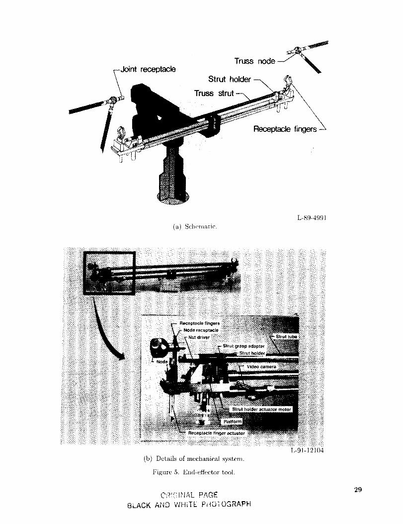
_-Jointreceptacle
!i
Truss node --__
Strut holder -_
(a) Schematic.
L-89-4991
iiiiiii!!iiil
iiiii!i:iii!iiil
(b) Details of mechanical system.
Figure 5. End-effector tool.
Ci?!GINAL PAGE
BLACK AND WHITE Pi-IOIOGRAPH
L-91-12104
29

F--
zZ0a.
0
CO
I.l.lu')
.<
t--<
I--
(2)<
z _0 o
T.<z
x >.Nr_O -- >_
I I I I I I
_, _ r---r'-r-n
_ _ m m 4-* _ m o
c _ I:L _ o o m_
I I I I I I I
o_
- = >_m o -
I I I I
I I
-- o L,J
_- el_ Lu
I 1 1 I
/r-- 1
v
L__I
o ._ _
,J
r_
_D
@
©
3O
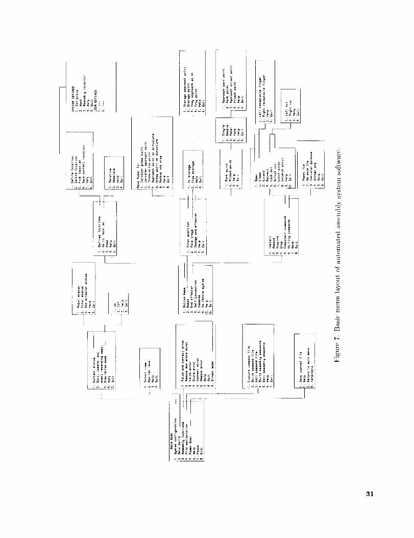
l
.+._+o-+ t _--_
i__+++i I .'"
oooa--_co3
I
o
o-
- uo
oou
o_=o
1211Iiii l
E -2_
_o
=+- c-
m+*- _;2
+.+__ +++
+ [--
"i ....
-M_4gd_
_P
++++++++ m
t -, _
g
B
_2
31
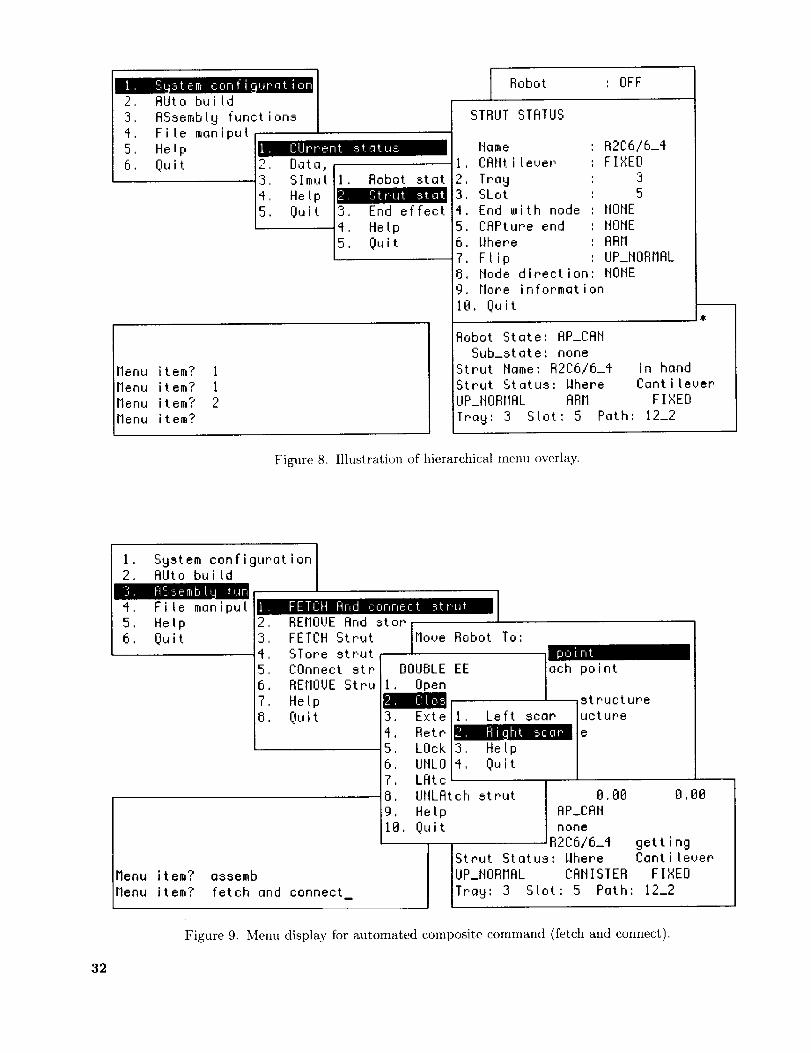
stem conf _l.+r.atio2. AUto build
3, ASsembly functions
4. File manipul
5, Help
6, Quit
CUrrent sta us
__", Data,:3, SImu I
4. Help
5, Quit
Robot statr'ut sta'
3, End effect
4. Help
5. Quit
Menu item? 1
Menu item? 1
Menu item? 2Menu item?
Robot : OFF
STRUT STATUS
Name
CANtilever
2 Tray3 SLot
4 End with node
5 CAPture end
6 Where
7 Flip8 Node direction
R2C616_4FIXED
3
5
NONE
NONE
ARM
UP_NORMAL
NONE
9 More information
18, Quit
Robot State: AP_CAN
Sub_state: none
Strut Name: R2C6/6_4 in hand
Strut Status: Where Cantilever
UP_NORMAL ARM FIXED
Tray: 3 Slot: 5 Path: 12_2
Figure 8. Illustration of hierarchical menu overlay.
I, System configuration2, AUto build
:3, A!-i:-;emb fu
FETCH _r,d cor, nec: str.tlt4, File maniput
5, Help
6, Quit4
5
6
7
8
REMOVE Arld storI
FETCH Strut IMove Robot To:
STor,e str,ut I _
COnnect str DOUBLE EE |ach point
REMOVE Stru iI
Help x istructureQuit 3. Exte [I, Left scar ucture
4.Retrl le5, LOokl3, Help I
6, UrtLO/4, Quit I7. LFItc8. UNLAtch strut t).L)I) I).1)13
9. Help AP_CAN18, Quit none
R2C6/6_4
Strut Status: ilhere
IUP_NORMAL CANISTER
Tray: 3 Slot: 5 Path:
Menu item? assemb
Menu item? fetch and connect
gettingCantilever
FIXED
12_2
Figure 9. Menu display for automated composite command (fetch and connect).
32
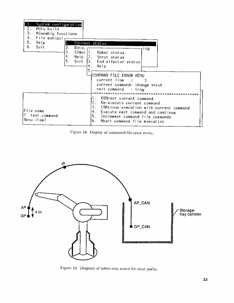
_ , System conf_uratiol2. AUto build
3. ASsembly functions
4. Fi!e manipu_
5, Help
6. Quit
CUrrent status
File name
? test,command
Menu item?
2. Data,3, Slmul
4, Hetp
5. Quit
ingII. Robot status I2, Strut status I13. End effector status
4, Help5
- CorlrIANDFILE ERROR MENU
current fine : 3
current command', change strut
next command : tray
CORrect current command
Re-execute current command
CONtinue execution with current command
Execute next command and continueIncrement command file commands
Abort command file execution
Figure 10. Display of command-file error menu.
IP
AP CAN
AP
GP
- _/-'Storage-
/ tray canister
GP_CAN
Figure 11. Diagram of robot-arm states for strut paths.
33

Strut instoIlation and removal:1. Direct2. Capture sequence3. Pyramid completion4. FreeEnd-effector actions:a. Capture or release second
_ __ . cantilevered nodeCa-n2_ ---"Ca--I; b. Close fingers on end with no node
.. _._ "_ L. 211,,_,_1 c. No nodes on either end of strut,_ close remaining end
\ _ d. Capture or release end of strut-td,I,LOpen_,_,.-- - -1 \ _/ e. Nostrutin hand
CANHGP CANI' 1_/''4 -- 4__]1_ _
Figure 12. Complete robot-arnl state diagram and logic. Dashed boxes indicate conditional states.
I, System2, AUto buitd3. ASse_:b[ ful
4, File manipul
5. Hetp
6, Quit
raFl_
D r'ect If_ode
Menu item? 3
Menu item? 9
Menu item? 3
Menu item?m
conf igurat ion I
I. FETCH
2, REMOVE And stor
3. FETCH Str.ut
4, STore strut
5. COnnect strut
6. REMOVE Strut
7, Help
8. Quit
And connect strut
Move Rob
I. CAIIIS
2. CANIS
4, Appro
5, Grasp6. Direc
7, Help8. Quit
ROBOT PAUSE MENU
[iProceed
AdjustReverse
MB: -88.88 8,88 8,OeRobot State: AP_CRN_TO_IP
Sub_state: noneStrut Name: R2C6/6_4 gettingStput Status: Where Cantilever
UP_NORMAL INSTALLED FIXED
Tray: 3 Slot: 5 Path: 12_2
Figure 13. Supervisor display of robot-arm pause menu.
34
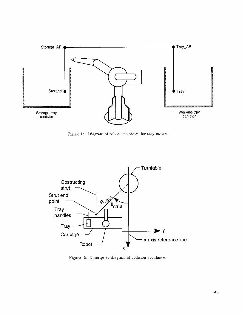
Storage_AP
Storage
Storage-traycanister
Figure 14. Diagram of robot-arm states for tray moves.
Tray_AP
Tray
Working-traycanister
Obstructingstrut
Strut end _'1 .
Tray ,..._..._/ . rut
handles --_ "Tray _ t..J ( K
Carriage --_
Robot -_x
_- Turntable
)
r Y
x-axis reference lineV
Figure 15. Descriptive diagram of collision avoidance.
35
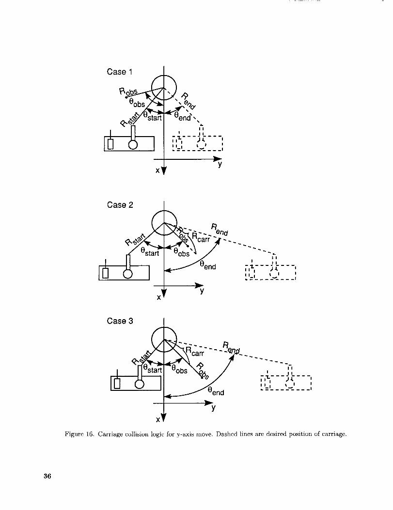
Case 1
%
II
I II
,,_,- - _) J.II I I I I
,-y
Case 2
x _
end ' *'_,_,- - __I I i i Iw.
--y
I
I
_1
Case 3
Rcarr
_y
×
II
I I I
,,_, )_ ,I I I I,..., I I
Figure 16. Carriage collision logic for y-axis move. Dashed lines are desired position of carriage.
36
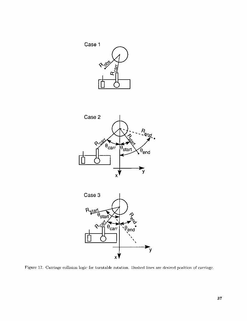
Case 1
a:
Case 2
XY
Case 3
X
)4
_'end
%
Vy
Figure 17. Carriage collision logic for turntable rotation. Dashed lines are desired position of carriage.
37
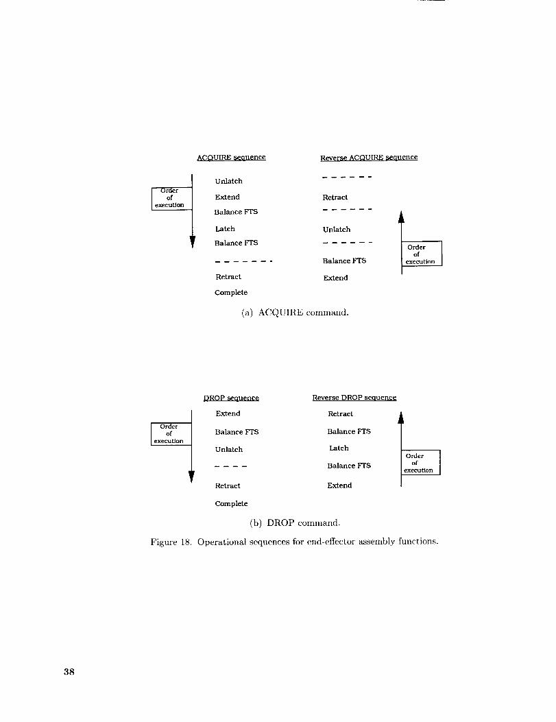
I Orderof
execution
_uence
Unlatch
Extend
Balance FTS
Latch
Balance FTS
Retract
Complete
Reverse ACQUIRE sequence
Retract
Unlatch
Balance FTS
Extend
IOrderof
execution
(a) ACQUIRE command.
Orderof
execution
Figure 18.
DROP sequence
Extend
Balance FTS
Unlatch
Retract
Complete
Reverse DROP seouence
Retract
Balance FTS
Latch
Balance FTS
Extend
Orderof
execution
(b) DROP command.
Operational sequences for end-effector assembly functions.
38
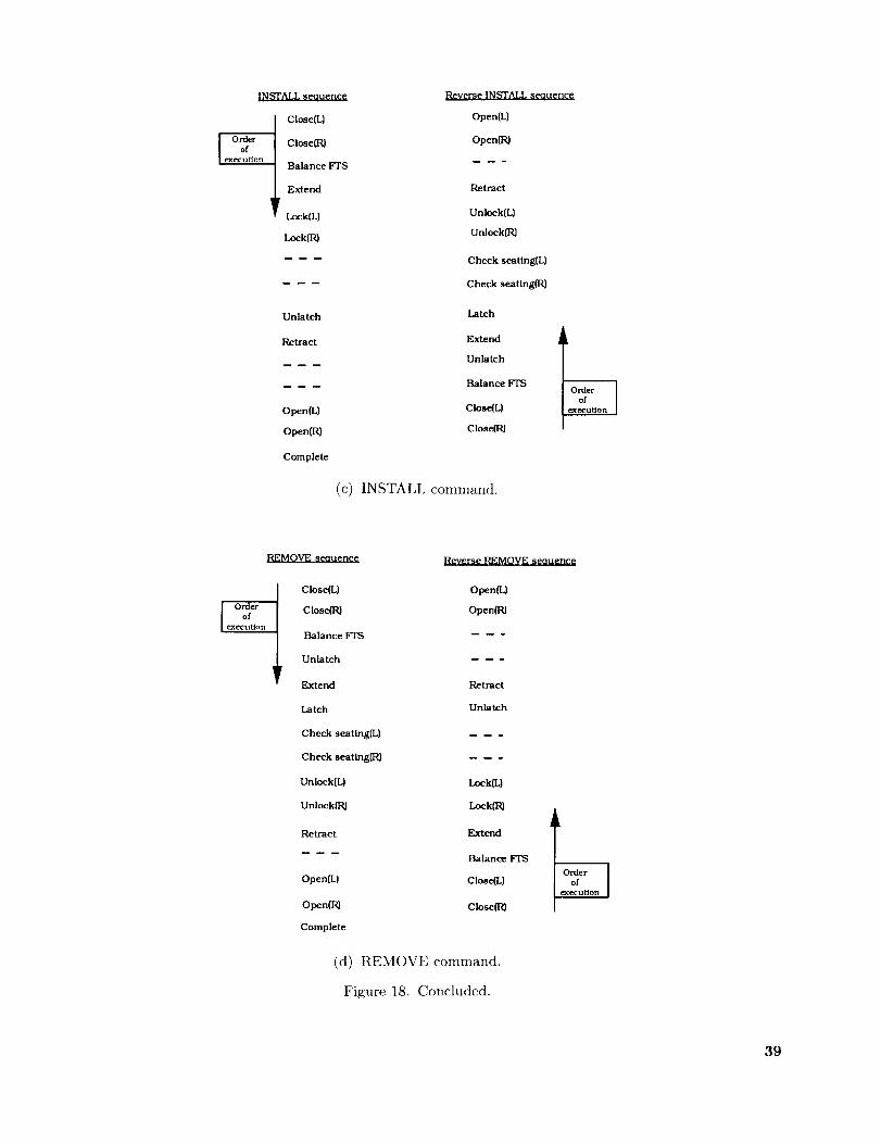
I Close(L}
10rd2u fer Close(R}ex tlon BaLance FTS
Extend
Lock(L}
Lock{R)
Unlatch
Retract
Open(L)
Open(R}
Complete
Reverse INSTALL seauence
Open(L}
Open{R)
Retract
Unlock(L}
Unlock(R}
Check seating(L}
Check seating(R}
Latch
Extend
Unlatch
Balance FTS
Close(L}
Close(Pd
(c) INSTALL command.
REMOVE seouence Reverse REMOVE seouence
Close(L}
Close_J
Balance FTS
Unlatch
Extend
Latch
Open(L)
Open(R)
Retract
Unlatch
Check seating(L}
Check seatingtR}
Unlock{L}
Unlock(R}
Lock(L}
Lock{R}
Retract
Open(L)
Open(R)
Complete
Extend
Balance FTS
Close(L}
Close(R)
(d) REMOVE command.
Figure 18. Concluded.
39
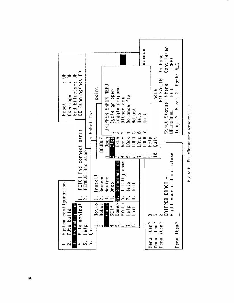
o0
o
r_)
e-'
0
I"0
f-I'-- °_
ill 0r..)
t-_r)
r_ ,'-r- |
@
;>©
©
?
4O

Record
MOTION BASE POSITION
STRUT TYPE
ROBOT STATUS
TRAY STATUS
Variable
X Car
Y--Car
Tl_rntable
Name
Where
Connect To
Loc In Tell
Node End
Cap End
C anti I eve r
Flip
Tray
Slot
State Pos
X, Y, Z, Roll, Pitch, Yaw
X_End, Y_End
State
Cond State
Strut Now
StrutlGetting_NowStrut Just Had
Tray_State
TrayMode
Current_Tray
Working_Ap
X, Y, Z, Roll, Pitch, Yaw
Storage Ap
X, Y, Z, Roll, Pitch, Yaw
Description
Motion-base configuration
Carriage x position
Carriage y position
Theta angle in degrees
Strut description
Strut na_%e
Current strut location
Struts needed for support
Installation position in truss
End withnode
End to capture
End conditions of strut
Flip indication
Tray ntu_ber containing strut
Position in tray
Position for each robot state
Core strut end points for collision avoidance
Manipulator arm current mode
Robot path location
Substate point in a path
Name of strut in arm, if any
Name of strut in process of retrieving
Name of last strut installed
Current tray locations and mode
Path location
Current tray operation
Tray on top
Robot position for working approach point
Robot position for storage approach point
TRAY HANDLE LOCATIONS
Storage_Loc
X, Y, Z, Roll, Pitch, Yaw
Working_Loc
X, Y, Z, Roll, Pitch, Yaw
STRUT
Left Seat
RighLSeat
Left Nut
_gh_ _t
CURRENT MOTION BASE POSITION
X Car
Y--Car
T_rntable
END EFFECTOR
LeftReceptacleFinger
R/ght_Receptacle_FingerPlatform
Latch
Storage Pos
X, Y, Z, Roll, Pitch, Yaw
Robot position in storage canister
Robot position in working canister
Strut currently in arm
Nut-driver alignment status
Nut status
Motion-base configuration
Carriage x position
Carriage y position
Lazy SuSan theta angle in degrees
End-effector status
Left receptacle fingers status
Right receptacle fingers status
Status of platform
Strut holders status
Robot position for storing
Figure 20. Data variables and descriptions.
41
43

REPORT DOCUMENTATION PAGEForm Approved
OMB No. 0704-0188
Public reporting burden for this collection of information is estimated to average ] hour per response, including the time for reviewing instructions, searching existing data sources,gathering and maintaining the data needed, and completing and reviewing the collection of information Send comments regarding this burden estimate or any other aspect of thiscollection of information, including suggestions for reducing this burden, to Washington Headquarters Services, Directorate for Information Operations and Reports, 1215 JeffersonDavis Highway, Suite 1204, Arlington, VA 22202-4302, and to the Office of Management and Budget, Paperwork Reduction Project (0704-0188), Washington, DC 20503
1. AGENCY USE ONLY(Leave blank) 2. REPORT DATE 3. REPORT TYPE AND DATES COVERED
June 1992 Technical Paper
4. TITLE AND SUBTITLE
Software Design for Automated Assembly of Truss Structures
6. AUTHOR(S)
Catherine L. Herstrom, Carolyn Grant.ham, Cheryl L. Allen
William R. Doggett, and Ralph W. Will
7. PERFORMING ORGANIZATION NAME(S) AND ADDRESS(ES)
NASA Langley Research Center
Hampton, VA 23665-5225
9. SPONSORING/MONITORING AGENCY NAME(S) AND ADDRESS(ES)
National Aeronautics and Space Administration
Wa_shington, DC 20546-0001
5. FUNDING NUMBERS
WU 506-43-41-02
8. PERFORMING ORGANIZATION
REPORT NUMBER
L-16983
10. SPONSORING/MONITORING
AGENCY REPORT NUMBER
NASA TP-3198
11, SUPPLEMENTARY NOTES
12a. DISTRIBUTION/AVAILABILITY STATEMENT
Unclassified -Unlimited
Subject Category 63
12b. DISTRIBUTION CODE
13. ABSTRACT (Maximum 200 words)
Concern over limited extravehicular and intravehicular activitiy time has increased the interest in performing
in-space assembly and construction operations with automated robotic systems. A technique being considered
at Langley Research Center is a supervised-autonomy approach, which can be monitored by an Earth-ba,sed
supervisor that intervenes only when the automated system encounters a problem. A test-bed to supportevaluation of the hardware and software requirements for supervised-autonomy assembly inethods has been
developed. This report describes the design of the software system necessary to support the a_ssembly process.
The system is implemented and successfully assembles and disassembles a planar tetrahedral truss structure.The software is hierarchical and supports both automated assembly operations and supervisor error-recovery
procedures, including the capability to pause and reverse any operation. The software design serves as a modelfor the development of software for more sophisticated automated systems and as a test-bed for evaluation of
new concepts and hardware components.
14. SUBJECT TERMS
Robotic; Assembly of truss structures; Automated assembly; Software design
17. SECURITY CLASSIFICATION
OF REPORT
Unclassified
_ISN 7540-01-280-5500
18. SECURITY CLASSIFICATION
OF THIS PAGE
Unclassified
19. SECURITY CLASSIFICATION
OF ABSTRACT
15. NUMBER OF PAGES
45
16. PRICE CODE
A0320. LIMITATION
OF ABSTRACT
iStandard Form 298(Rev. 2-89)Prescribed by ANSI Std Z3g-18298-i02
Related Documents