Smart Media System Software Configuration Guide Sales Office: +1 (301) 975-1000 Technical Support: +1 (301) 975-1007 E-mail: [email protected] Web: www.patton.com Part Number: 07MSMARTMEDIA-SCG, Rev. A Revised: January 12, 2012

Welcome message from author
This document is posted to help you gain knowledge. Please leave a comment to let me know what you think about it! Share it to your friends and learn new things together.
Transcript

Smart Media System
Software Configuration Guide
Sales Office: +1 (301) 975-1000Technical Support: +1 (301) 975-1007
E-mail: [email protected]: www.patton.com
Part Number: 07MSMARTMEDIA-SCG, Rev. ARevised: January 12, 2012

Patton Electronics Company, Inc.7622 Rickenbacker Drive
Gaithersburg, MD 20879 USAtel: +1 (301) 975-1000fax: +1 (301) 869-9293
support: +1 (301) 975-1007web: www.patton.com
e-mail: [email protected]
CopyrightCopyright © 2012, Patton Electronics Company. All rights reserved.
NoticeThe information in this document is subject to change without notice. Patton Electronics assumes no liability for errors that may appear in this document.
The software described in this document is furnished under a license and may be used or copied only in accordance with the terms of such license.
Supported Models
SN10200/16E/UI SN10200/1DS3/UI SN10200/STM1/UISN10200/32E/UI SN10200/2DS3/UISN10200/48E/UI

3
Summary Table of Contents
1 Getting Started with the Web Portal ............................................................................................................. 22
2 Configuring VoIP Interfaces ......................................................................................................................... 36
3 Configuring an ISDN-SIP Gateway .............................................................................................................. 42
4 Configuring SS7 Signaling ............................................................................................................................ 80
5 Configuring SIGTRAN Applications .......................................................................................................... 112
6 Configuring CAS R2 ................................................................................................................................... 191
7 Configuring H.248...................................................................................................................................... 203
8 Configuring SNMP ..................................................................................................................................... 220
9 Contacting Patton ....................................................................................................................................... 226

Table of Contents
Audience............................................................................................................................................................... 21
Structure............................................................................................................................................................... 21
1 Getting Started with the Web Portal ............................................................................................................. 22Overview ...............................................................................................................................................................23
Accessing and Navigating the Web Interface .........................................................................................................23
Connecting to the web server and logging on to the Web Portal .....................................................................23Connecting to the web server ....................................................................................................................23
Logging on to the Web Portal ...................................................................................................................23
Navigating the Web Portal ..............................................................................................................................23Navigation and Information Panels ...........................................................................................................23
Knowing Your Location ............................................................................................................................24
Managing Users.....................................................................................................................................................25Understanding User Access Levels ...................................................................................................................25
Viewing the User List ......................................................................................................................................25
Creating a New User .......................................................................................................................................26Deleting a User ...............................................................................................................................................27
Logging Off ....................................................................................................................................................27
Managing the Database Backup.............................................................................................................................28Carrying out a First Database Backup .............................................................................................................28
Downloading a Database Backup ....................................................................................................................29
Uploading a Database Backup ........................................................................................................................29Restoring a Database Backup ..........................................................................................................................29
Working with Configurations................................................................................................................................30
Managing Applications ...................................................................................................................................30Viewing the List of Installed Applications .................................................................................................30
Starting an Application .............................................................................................................................30
Verifying that an Application is Operating ................................................................................................32Verifying the Application Path ..................................................................................................................32
Activating the Configuration ..........................................................................................................................33
Verifying status .........................................................................................................................................34
2 Configuring VoIP Interfaces ......................................................................................................................... 36Overview ...............................................................................................................................................................37
Configuring Interfaces ...........................................................................................................................................37
Understanding Parameters for IP Interfaces ....................................................................................................38Viewing the Status of Interfaces.............................................................................................................................39
Adapters (General View) .................................................................................................................................39
Adapters (Detailed View) ................................................................................................................................39Hardware ..................................................................................................................................................40
Sensors ......................................................................................................................................................40
Licensed Features ......................................................................................................................................41
4

Smart Media Software Configuration Guide Table of Contents
IP Interfaces (Detailed View) ..........................................................................................................................41
3 Configuring an ISDN-SIP Gateway .............................................................................................................. 42Overview ...............................................................................................................................................................44
Creating a New Configuration ..............................................................................................................................44Allocating Physical Interfaces.................................................................................................................................46
Creating a new line interface ...........................................................................................................................46
Understanding Parameters for Line Interfaces ...........................................................................................47Creating a new line service ..............................................................................................................................48
Understanding Parameters for Line Services ..............................................................................................50
Creating an IP port range ................................................................................................................................50
Understanding Parameters for IP Port Ranges ...........................................................................................51Configuring ISDN-PRI Signaling .........................................................................................................................52
Understanding Parameters for ISDN Stacks ....................................................................................................53
Defining a Clocking Source...................................................................................................................................54Understanding Parameters for the System Clock .............................................................................................55
Configuring SIP Signaling.....................................................................................................................................55
Creating a SIP stack ........................................................................................................................................55Understanding Parameters for SIP Stacks ..................................................................................................57
Creating a SIP transport server ........................................................................................................................57
Understanding Parameters for SIP Transport Servers ................................................................................58Creating a SIP service access point (SAP) ........................................................................................................59
Understanding Parameters for SIP SAPs ....................................................................................................60
Configuring Codecs and Tone Detection ..............................................................................................................60Accessing Profiles and Validating Settings .......................................................................................................60
Managing the Session Description Protocol (SDP) .........................................................................................62
Media Announcement ...............................................................................................................................62Attribute for Media Announcement ..........................................................................................................63
Configuring Network Access Points (NAPs)..........................................................................................................65
Allocating an ISDN NAP ...............................................................................................................................65Understanding Parameters for ISDN NAPs ..............................................................................................66
Allocating a SIP NAP ......................................................................................................................................66
Understanding Parameters for SIP NAPs ..................................................................................................68Creating Call Routing Rules..................................................................................................................................69
Creating a primary call route ...........................................................................................................................69
Understanding Parameters for Call Routing ..............................................................................................71Viewing the Status of the TDM Lines ...................................................................................................................72
General View ..................................................................................................................................................72
Detailed View .................................................................................................................................................73Line Interface ............................................................................................................................................73
Line Service ...............................................................................................................................................73
Viewing the Status of the ISDN Stack...................................................................................................................74General View ..................................................................................................................................................74
Timeslot States Diagram .................................................................................................................................75
5

Smart Media Software Configuration Guide Table of Contents
Viewing the Status of the SIP Stack.......................................................................................................................76
General View ..................................................................................................................................................76
Detailed View .................................................................................................................................................77SIP Stack Configuration Status .................................................................................................................77
SIP SAP Detailed Status ............................................................................................................................78
Viewing the Status of the NAPs.............................................................................................................................79General View ..................................................................................................................................................79
4 Configuring SS7 Signaling ............................................................................................................................ 80Overview ...............................................................................................................................................................82
Configuring the MTP2 Layer ................................................................................................................................82
Creating an MTP2 Configuration ...................................................................................................................82Understanding Parameters for MTP2 Configurations ...............................................................................83
Creating MTP2 Links .....................................................................................................................................83
Understanding Parameters for MTP2 Links ..............................................................................................85Configuring the MTP3 Layer ................................................................................................................................86
Creating an MTP3 Configuration ...................................................................................................................86
Understanding Parameters for MTP3 Configurations ...............................................................................87Creating an MTP3 Network ...........................................................................................................................87
Understanding Parameters for MTP3 Networks .......................................................................................88
Creating an MTP3 Point Code .......................................................................................................................88Understanding Parameters for SS7 Point Codes ........................................................................................89
Creating an MTP3 Linkset .............................................................................................................................90
Understanding Parameters for MTP3 Linksets ..........................................................................................91Creating MTP3 Links .....................................................................................................................................91
Understanding Parameters for MTP3 Links ..............................................................................................93
Creating an MTP3 Route ...............................................................................................................................93Understanding Parameters for MTP3 Routes ............................................................................................95
Configuring the ISUP Layer..................................................................................................................................95
Creating an ISUP Stack ..................................................................................................................................95Understanding Parameters for ISUP Stacks ...............................................................................................96
Creating an ISUP Network .............................................................................................................................97
Understanding Parameters for ISUP Networks .........................................................................................98Creating an ISUP User Part ............................................................................................................................98
Understanding Parameters for ISUP User Parts .........................................................................................99
Creating an ISUP Interface ...........................................................................................................................100Understanding Parameters for ISUP Interfaces ........................................................................................101
.....................................................................................................................................................................101
Viewing the Status of SS7 MTP2 Links...............................................................................................................102General View ................................................................................................................................................102
Detailed View ...............................................................................................................................................102
MTP2 Link Detailed Status ....................................................................................................................102MTP2 Link Listing .................................................................................................................................103
Viewing the Status of SS7 MTP3 Links...............................................................................................................104
6

Smart Media Software Configuration Guide Table of Contents
General View ................................................................................................................................................104
Detailed View ...............................................................................................................................................104
MTP3 Stack Status .................................................................................................................................105MTP3 Linkset .........................................................................................................................................105
MTP3 Link .............................................................................................................................................107
Viewing the Status of SS7 ISUP Stacks................................................................................................................108General View ................................................................................................................................................108
Detailed View ...............................................................................................................................................109
ISUP Stack Status ...................................................................................................................................109ISUP Interface Status ..............................................................................................................................110
Circuit Group Status ...............................................................................................................................111
5 Configuring SIGTRAN Applications .......................................................................................................... 112Overview .............................................................................................................................................................115
Configuring an M2PA System.............................................................................................................................116Adding an Adapter ........................................................................................................................................117
Understanding Parameters for Hardware Adapters ..................................................................................119
Creating Line Interfaces ................................................................................................................................119Understanding Parameters for Line Interfaces .........................................................................................120
Creating Line Services ...................................................................................................................................121
Understanding Parameters for Line Services ............................................................................................123Creating the SCTP Configuration ................................................................................................................124
Understanding Parameters for SCTP Configurations ..............................................................................124
Creating an M2PA Configuration .................................................................................................................125Understanding Parameters for M2PA Configurations .............................................................................125
Creating an M2PA SAP ................................................................................................................................126
Understanding Parameters for M2PA SAPs .............................................................................................127Creating M2PA Links ...................................................................................................................................127
Understanding Parameters for M2PA Links ............................................................................................128
Creating SS7 Point Codes .............................................................................................................................129Understanding Parameters for SS7 Point Codes ......................................................................................130
Creating an MTP3 Configuration .................................................................................................................131
Understanding Parameters for MTP3 Configurations .............................................................................132Creating an MTP3 Network .........................................................................................................................132
Understanding Parameters for MTP3 Networks .....................................................................................133
Creating an MTP3 Linkset ...........................................................................................................................133Understanding Parameters for MTP3 Linksets ........................................................................................134
Creating MTP3 Links (M2PA) .....................................................................................................................134
Understanding Parameters for MTP3 (M2PA) Links ..............................................................................136Creating an MTP3 Route .............................................................................................................................136
Understanding Parameters for MTP3 Routes ..........................................................................................138
Creating an ISUP Stack ................................................................................................................................138Understanding Parameters for ISUP Stacks .............................................................................................139
Creating an ISUP Network ...........................................................................................................................139
7

Smart Media Software Configuration Guide Table of Contents
Understanding Parameters for ISUP Networks .......................................................................................140
Creating an ISUP User Part ..........................................................................................................................141
Understanding Parameters for ISUP User Parts .......................................................................................142Creating an ISUP Interface ...........................................................................................................................142
Understanding Parameters for ISUP Interfaces ........................................................................................143
Creating ISUP CIC Groups ..........................................................................................................................144Understanding Parameters for ISUP CIC Groups ...................................................................................145
Creating a NAP (SIGTRAN) ........................................................................................................................145
Understanding Parameters for NAPs (SIGTRAN) ..................................................................................147Configuring an M2UA System on a Signaling Gateway.......................................................................................148
Creating an MTP2 Configuration .................................................................................................................148
Understanding Parameters for MTP2 Configurations .............................................................................149
Creating MTP2 Links ...................................................................................................................................149Understanding Parameters for MTP2 Links ............................................................................................151
Creating an M2UA Configuration ................................................................................................................151
Understanding Parameters for M2UA Configurations ............................................................................152Creating an M2UA SAP ...............................................................................................................................152
Understanding Parameters for M2UA SAPs ............................................................................................153
Creating an M2UA Cluster ...........................................................................................................................153Understanding Parameters for M2UA Clusters .......................................................................................154
Creating M2UA Links ..................................................................................................................................154
Understanding Parameters for M2UA Links ...........................................................................................155Creating M2UA Peers ...................................................................................................................................156
Understanding Parameters for M2UA Peers ............................................................................................157
Configuring an M2UA System on a Media Gateway Controller..........................................................................158Creating MTP3 Links (M2UA) ....................................................................................................................159
Understanding Parameters for MTP3 (M2UA) Links .............................................................................159
Configuring an IUA System on a Signaling Gateway...........................................................................................160Creating an IUA Configuration ....................................................................................................................160
Understanding Parameters for IUA Configurations .................................................................................161
Creating an IUA SAP ....................................................................................................................................161Understanding Parameters for IUA SAPs ................................................................................................162
Creating an IUA Cluster ...............................................................................................................................162
Understanding Parameters for IUA Clusters ............................................................................................163Creating IUA Links ......................................................................................................................................163
Understanding Parameters for IUA Links ................................................................................................164
Creating IUA Peers .......................................................................................................................................164Understanding Parameters for IUA Peers ................................................................................................165
Configuring an M3UA System on IP Signaling Points ........................................................................................166
Creating an M3UA Configuration (IPSP) .....................................................................................................167Understanding Parameters for M3UA Configurations ............................................................................167
Creating an M3UA SAP ...............................................................................................................................168
Understanding Parameters for M3UA SAPs ............................................................................................169Creating an M3UA Network ........................................................................................................................169
8

Smart Media Software Configuration Guide Table of Contents
Understanding Parameters for M3UA Networks .....................................................................................170
Creating an M3UA User Part .......................................................................................................................170
Understanding Parameters for M3UA User Parts ....................................................................................171Creating an M3UA Peer Signaling Process (IPSP) ........................................................................................171
Understanding Parameters for M3UA PSPs ............................................................................................172
Creating an M3UA Peer Server .....................................................................................................................173Understanding Parameters for M3UA Peer Servers .................................................................................174
Creating an M3UA Route .............................................................................................................................175
Understanding Parameters for M3UA Routes .........................................................................................176Configuring an M3UA System on a Signaling Gateway.......................................................................................177
Creating MTP3 Links (M3UA) ....................................................................................................................178
Understanding Parameters for MTP3 (M3UA) Links .............................................................................179
Creating an M3UA Configuration (SGP) .....................................................................................................180Understanding Parameters for M3UA Configurations ............................................................................180
Creating an M3UA Peer Signaling Process (SGP) .........................................................................................181
Understanding Parameters for M3UA PSPs ............................................................................................182Creating an M3UA Route (SGP) ..................................................................................................................183
Understanding Parameters for M3UA Routes .........................................................................................184
Configuring an M3UA System on an Application Server.....................................................................................185Creating an M3UA Configuration (ASP) ......................................................................................................186
Understanding Parameters for M3UA Configurations ............................................................................186
Creating an M3UA Peer Signaling Process (ASP) .........................................................................................187Understanding Parameters for M3UA PSPs ............................................................................................188
Creating an M3UA ISUP Network ...............................................................................................................189
Understanding Parameters for M3UA ISUP Networks ...........................................................................190
6 Configuring CAS R2 ................................................................................................................................... 191Overview .............................................................................................................................................................192
Adding an Adapter ..............................................................................................................................................192
Understanding Parameters for Hardware Adapters ..................................................................................194Creating Line Interfaces ................................................................................................................................194
Understanding Parameters for Line Interfaces .........................................................................................195
Creating Line Services ...................................................................................................................................196Understanding Parameters for Line Services ..................................................................................................198
Copying a Variant Script (optional).....................................................................................................................199
Creating a CAS R2 Stack.....................................................................................................................................200Understanding Parameters for CAS R2 Stacks ..............................................................................................201
Creating a CAS R2 NAP .....................................................................................................................................201
Understanding Parameters for NAPs .............................................................................................................202
7 Configuring H.248...................................................................................................................................... 203Overview .............................................................................................................................................................204
Adding an Adapter ..............................................................................................................................................204
Understanding Parameters for Hardware Adapters ..................................................................................206Creating Line Interfaces ................................................................................................................................206
9

Smart Media Software Configuration Guide Table of Contents
Understanding Parameters for Line Interfaces .........................................................................................207
Creating Line Services ...................................................................................................................................208
Creating an IP Port Range...................................................................................................................................210Creating an IP port range ..............................................................................................................................210
Understanding Parameters for IP Port Ranges ...............................................................................................211
Configuring Network Access Points (NAPs)........................................................................................................212Allocating a VoIP network access point (NAP) .............................................................................................212
Understanding Parameters for VoIP NAPs ..............................................................................................213
Allocating a TDM Network Access Point (NAP) ..........................................................................................213Understanding Parameters for TDM NAPs ............................................................................................214
Configuring the Media Gateway for H.248 Mode...............................................................................................215
Creating an H.248 Configuration .......................................................................................................................216
Understanding Parameters for H.248 Configuration ....................................................................................217Adding a New Media Gateway Controller (MGC)..............................................................................................217
Understanding Parameters for Media Gateway Controller ............................................................................218
Associating NAPs with the H.248 Configuration ................................................................................................218Selecting Timeslots for TDM Interfaces ..............................................................................................................219
8 Configuring SNMP ..................................................................................................................................... 220Overview .............................................................................................................................................................221
Activating the tbSnmpAgent................................................................................................................................221Disabling the SELinux Service ......................................................................................................................221
Activating the tbSnmpAgent application .......................................................................................................222
Configuring the tbSnmpAgent ............................................................................................................................223Configuring SNMP system parameters .........................................................................................................223
Configuring SNMPv1, SNMPv2c ................................................................................................................225
Configuring SNMPv3 ...................................................................................................................................225Configuring traps ..........................................................................................................................................225
9 Contacting Patton ....................................................................................................................................... 226Introduction........................................................................................................................................................227
Contact information............................................................................................................................................227Patton support headquarters in the USA .......................................................................................................227
Alternate Patton support for Europe, Middle East, and Africa (EMEA) ........................................................227
Warranty Service and Returned Merchandise Authorizations (RMAs).................................................................227Warranty coverage ........................................................................................................................................227
Out-of-warranty service ...........................................................................................................................228
Returns for credit ....................................................................................................................................228Return for credit policy ...........................................................................................................................228
RMA numbers ..............................................................................................................................................228
Shipping instructions ..............................................................................................................................228
10

List of Figures
1 SmartNode Web Portal Navigation . . . . . . . . . . . . . . . . . . . . . . . . . . . . . . . . . . . . . . . . . . . . . . . . . . . . . . . . . 242 SmartNode Web Portal Menus . . . . . . . . . . . . . . . . . . . . . . . . . . . . . . . . . . . . . . . . . . . . . . . . . . . . . . . . . . . . . 243 SmartNode User Access Levels . . . . . . . . . . . . . . . . . . . . . . . . . . . . . . . . . . . . . . . . . . . . . . . . . . . . . . . . . . . . . 254 Global > Users . . . . . . . . . . . . . . . . . . . . . . . . . . . . . . . . . . . . . . . . . . . . . . . . . . . . . . . . . . . . . . . . . . . . . . . . . 255 User List . . . . . . . . . . . . . . . . . . . . . . . . . . . . . . . . . . . . . . . . . . . . . . . . . . . . . . . . . . . . . . . . . . . . . . . . . . . . . . 266 User List > Create New User . . . . . . . . . . . . . . . . . . . . . . . . . . . . . . . . . . . . . . . . . . . . . . . . . . . . . . . . . . . . . . 267 User List > Delete User . . . . . . . . . . . . . . . . . . . . . . . . . . . . . . . . . . . . . . . . . . . . . . . . . . . . . . . . . . . . . . . . . . . 278 Navigation Menu: Logout . . . . . . . . . . . . . . . . . . . . . . . . . . . . . . . . . . . . . . . . . . . . . . . . . . . . . . . . . . . . . . . . 279 Global > Backups . . . . . . . . . . . . . . . . . . . . . . . . . . . . . . . . . . . . . . . . . . . . . . . . . . . . . . . . . . . . . . . . . . . . . . . 2810 Backups > Create new database backup . . . . . . . . . . . . . . . . . . . . . . . . . . . . . . . . . . . . . . . . . . . . . . . . . . . . . . 2811 Database Backup Message . . . . . . . . . . . . . . . . . . . . . . . . . . . . . . . . . . . . . . . . . . . . . . . . . . . . . . . . . . . . . . . . . 2812 Database Backup List . . . . . . . . . . . . . . . . . . . . . . . . . . . . . . . . . . . . . . . . . . . . . . . . . . . . . . . . . . . . . . . . . . . . 2813 Download Database Backup . . . . . . . . . . . . . . . . . . . . . . . . . . . . . . . . . . . . . . . . . . . . . . . . . . . . . . . . . . . . . . . 2914 Upload Database Backup File . . . . . . . . . . . . . . . . . . . . . . . . . . . . . . . . . . . . . . . . . . . . . . . . . . . . . . . . . . . . . . 2915 Restore Database Backup File . . . . . . . . . . . . . . . . . . . . . . . . . . . . . . . . . . . . . . . . . . . . . . . . . . . . . . . . . . . . . . 2916 Applications > Instances . . . . . . . . . . . . . . . . . . . . . . . . . . . . . . . . . . . . . . . . . . . . . . . . . . . . . . . . . . . . . . . . . . 3017 Application Instance List . . . . . . . . . . . . . . . . . . . . . . . . . . . . . . . . . . . . . . . . . . . . . . . . . . . . . . . . . . . . . . . . . 3018 Application Instance List > Edit . . . . . . . . . . . . . . . . . . . . . . . . . . . . . . . . . . . . . . . . . . . . . . . . . . . . . . . . . . . . 3119 Application Status . . . . . . . . . . . . . . . . . . . . . . . . . . . . . . . . . . . . . . . . . . . . . . . . . . . . . . . . . . . . . . . . . . . . . . . 3120 Apply States . . . . . . . . . . . . . . . . . . . . . . . . . . . . . . . . . . . . . . . . . . . . . . . . . . . . . . . . . . . . . . . . . . . . . . . . . . . 3121 SmartNode Interfaces . . . . . . . . . . . . . . . . . . . . . . . . . . . . . . . . . . . . . . . . . . . . . . . . . . . . . . . . . . . . . . . . . . . . 3222 Application Status List . . . . . . . . . . . . . . . . . . . . . . . . . . . . . . . . . . . . . . . . . . . . . . . . . . . . . . . . . . . . . . . . . . . 3223 Global > Systems . . . . . . . . . . . . . . . . . . . . . . . . . . . . . . . . . . . . . . . . . . . . . . . . . . . . . . . . . . . . . . . . . . . . . . . 3324 System List . . . . . . . . . . . . . . . . . . . . . . . . . . . . . . . . . . . . . . . . . . . . . . . . . . . . . . . . . . . . . . . . . . . . . . . . . . . . 3325 Name and Activate Configuration . . . . . . . . . . . . . . . . . . . . . . . . . . . . . . . . . . . . . . . . . . . . . . . . . . . . . . . . . . 3326 Successful Activation . . . . . . . . . . . . . . . . . . . . . . . . . . . . . . . . . . . . . . . . . . . . . . . . . . . . . . . . . . . . . . . . . . . . . 3427 Global > Status . . . . . . . . . . . . . . . . . . . . . . . . . . . . . . . . . . . . . . . . . . . . . . . . . . . . . . . . . . . . . . . . . . . . . . . . . 3428 Status: General View . . . . . . . . . . . . . . . . . . . . . . . . . . . . . . . . . . . . . . . . . . . . . . . . . . . . . . . . . . . . . . . . . . . . . 3529 Status: Detailed View . . . . . . . . . . . . . . . . . . . . . . . . . . . . . . . . . . . . . . . . . . . . . . . . . . . . . . . . . . . . . . . . . . . . 3530 Menu > IP Interfaces . . . . . . . . . . . . . . . . . . . . . . . . . . . . . . . . . . . . . . . . . . . . . . . . . . . . . . . . . . . . . . . . . . . . 3731 IP Interface List . . . . . . . . . . . . . . . . . . . . . . . . . . . . . . . . . . . . . . . . . . . . . . . . . . . . . . . . . . . . . . . . . . . . . . . . 3732 Editing an IP Interface . . . . . . . . . . . . . . . . . . . . . . . . . . . . . . . . . . . . . . . . . . . . . . . . . . . . . . . . . . . . . . . . . . . 3833 Adapters (General View) . . . . . . . . . . . . . . . . . . . . . . . . . . . . . . . . . . . . . . . . . . . . . . . . . . . . . . . . . . . . . . . . . . 3934 Adapters (Detailed View) > Hardware . . . . . . . . . . . . . . . . . . . . . . . . . . . . . . . . . . . . . . . . . . . . . . . . . . . . . . . 4035 Adapters (Detailed View) > Sensors . . . . . . . . . . . . . . . . . . . . . . . . . . . . . . . . . . . . . . . . . . . . . . . . . . . . . . . . . 4036 Adapters (Detailed View) > Licensed Features . . . . . . . . . . . . . . . . . . . . . . . . . . . . . . . . . . . . . . . . . . . . . . . . . . 4137 IP Interfaces (Detailed View) . . . . . . . . . . . . . . . . . . . . . . . . . . . . . . . . . . . . . . . . . . . . . . . . . . . . . . . . . . . . . . 4138 Global > Configurations . . . . . . . . . . . . . . . . . . . . . . . . . . . . . . . . . . . . . . . . . . . . . . . . . . . . . . . . . . . . . . . . . . 4439 Configuration List . . . . . . . . . . . . . . . . . . . . . . . . . . . . . . . . . . . . . . . . . . . . . . . . . . . . . . . . . . . . . . . . . . . . . . 4540 Name and Copy a Configuration File . . . . . . . . . . . . . . . . . . . . . . . . . . . . . . . . . . . . . . . . . . . . . . . . . . . . . . . . 4541 Successful Configuration Copy . . . . . . . . . . . . . . . . . . . . . . . . . . . . . . . . . . . . . . . . . . . . . . . . . . . . . . . . . . . . . 4542 TDM Interfaces > Line Interfaces . . . . . . . . . . . . . . . . . . . . . . . . . . . . . . . . . . . . . . . . . . . . . . . . . . . . . . . . . . . 4643 Line Interface List . . . . . . . . . . . . . . . . . . . . . . . . . . . . . . . . . . . . . . . . . . . . . . . . . . . . . . . . . . . . . . . . . . . . . . . 4644 Create New Line Interface . . . . . . . . . . . . . . . . . . . . . . . . . . . . . . . . . . . . . . . . . . . . . . . . . . . . . . . . . . . . . . . . 4745 Confirmation Message for New Line Interface . . . . . . . . . . . . . . . . . . . . . . . . . . . . . . . . . . . . . . . . . . . . . . . . . 4746 TDM Interfaces > Line Interfaces . . . . . . . . . . . . . . . . . . . . . . . . . . . . . . . . . . . . . . . . . . . . . . . . . . . . . . . . . . . 4847 Line Interface List . . . . . . . . . . . . . . . . . . . . . . . . . . . . . . . . . . . . . . . . . . . . . . . . . . . . . . . . . . . . . . . . . . . . . . . 48
11

Smart Media Software Configuration Guide
48 Editing a Line Interface to Create a New Service . . . . . . . . . . . . . . . . . . . . . . . . . . . . . . . . . . . . . . . . . . . . . . . 4849 Create New Line Service . . . . . . . . . . . . . . . . . . . . . . . . . . . . . . . . . . . . . . . . . . . . . . . . . . . . . . . . . . . . . . . . . . 4950 Line Services List . . . . . . . . . . . . . . . . . . . . . . . . . . . . . . . . . . . . . . . . . . . . . . . . . . . . . . . . . . . . . . . . . . . . . . . 4951 Menu: IP Interfaces . . . . . . . . . . . . . . . . . . . . . . . . . . . . . . . . . . . . . . . . . . . . . . . . . . . . . . . . . . . . . . . . . . . . . 5052 Editing Port Ranges . . . . . . . . . . . . . . . . . . . . . . . . . . . . . . . . . . . . . . . . . . . . . . . . . . . . . . . . . . . . . . . . . . . . . 5153 Creating a New Port Range . . . . . . . . . . . . . . . . . . . . . . . . . . . . . . . . . . . . . . . . . . . . . . . . . . . . . . . . . . . . . . . 5154 Confirmation Message for Port Range . . . . . . . . . . . . . . . . . . . . . . . . . . . . . . . . . . . . . . . . . . . . . . . . . . . . . . . 5155 Signaling > ISDN . . . . . . . . . . . . . . . . . . . . . . . . . . . . . . . . . . . . . . . . . . . . . . . . . . . . . . . . . . . . . . . . . . . . . . . 5256 ISDN Stack List . . . . . . . . . . . . . . . . . . . . . . . . . . . . . . . . . . . . . . . . . . . . . . . . . . . . . . . . . . . . . . . . . . . . . . . . 5257 Create New ISDN Stack . . . . . . . . . . . . . . . . . . . . . . . . . . . . . . . . . . . . . . . . . . . . . . . . . . . . . . . . . . . . . . . . . . 5358 Confirmation Message for New ISDN Stack . . . . . . . . . . . . . . . . . . . . . . . . . . . . . . . . . . . . . . . . . . . . . . . . . . 5359 Menu: Clocking . . . . . . . . . . . . . . . . . . . . . . . . . . . . . . . . . . . . . . . . . . . . . . . . . . . . . . . . . . . . . . . . . . . . . . . . 5460 External System Clock Reference List . . . . . . . . . . . . . . . . . . . . . . . . . . . . . . . . . . . . . . . . . . . . . . . . . . . . . . . . 5461 Creating New External System Clock . . . . . . . . . . . . . . . . . . . . . . . . . . . . . . . . . . . . . . . . . . . . . . . . . . . . . . . . 5462 Confirmation Message for System Clock . . . . . . . . . . . . . . . . . . . . . . . . . . . . . . . . . . . . . . . . . . . . . . . . . . . . . 5463 Menu: SIP . . . . . . . . . . . . . . . . . . . . . . . . . . . . . . . . . . . . . . . . . . . . . . . . . . . . . . . . . . . . . . . . . . . . . . . . . . . . 5564 SIP Configuration List . . . . . . . . . . . . . . . . . . . . . . . . . . . . . . . . . . . . . . . . . . . . . . . . . . . . . . . . . . . . . . . . . . . 5665 Creating a New SIP Stack . . . . . . . . . . . . . . . . . . . . . . . . . . . . . . . . . . . . . . . . . . . . . . . . . . . . . . . . . . . . . . . . . 5666 Confirmation Message for SIP . . . . . . . . . . . . . . . . . . . . . . . . . . . . . . . . . . . . . . . . . . . . . . . . . . . . . . . . . . . . . 5667 Menu: SIP . . . . . . . . . . . . . . . . . . . . . . . . . . . . . . . . . . . . . . . . . . . . . . . . . . . . . . . . . . . . . . . . . . . . . . . . . . . . 5768 Edit SIP Configuration List . . . . . . . . . . . . . . . . . . . . . . . . . . . . . . . . . . . . . . . . . . . . . . . . . . . . . . . . . . . . . . . 5769 Transport Servers List . . . . . . . . . . . . . . . . . . . . . . . . . . . . . . . . . . . . . . . . . . . . . . . . . . . . . . . . . . . . . . . . . . . . 5770 Creating a New SIP Transport Server . . . . . . . . . . . . . . . . . . . . . . . . . . . . . . . . . . . . . . . . . . . . . . . . . . . . . . . . 5871 Confirmation Message for SIP Transport Server . . . . . . . . . . . . . . . . . . . . . . . . . . . . . . . . . . . . . . . . . . . . . . . . 5872 Menu: SIP . . . . . . . . . . . . . . . . . . . . . . . . . . . . . . . . . . . . . . . . . . . . . . . . . . . . . . . . . . . . . . . . . . . . . . . . . . . . 5973 Edit SIP Configuration List . . . . . . . . . . . . . . . . . . . . . . . . . . . . . . . . . . . . . . . . . . . . . . . . . . . . . . . . . . . . . . . 5974 Service Access Points (SAP) List . . . . . . . . . . . . . . . . . . . . . . . . . . . . . . . . . . . . . . . . . . . . . . . . . . . . . . . . . . . . 5975 Creating a New SAP . . . . . . . . . . . . . . . . . . . . . . . . . . . . . . . . . . . . . . . . . . . . . . . . . . . . . . . . . . . . . . . . . . . . . 5976 Confirmation Message for SIP SAP . . . . . . . . . . . . . . . . . . . . . . . . . . . . . . . . . . . . . . . . . . . . . . . . . . . . . . . . . 5977 Associating Transport Servers . . . . . . . . . . . . . . . . . . . . . . . . . . . . . . . . . . . . . . . . . . . . . . . . . . . . . . . . . . . . . . 6078 Menu: Profiles . . . . . . . . . . . . . . . . . . . . . . . . . . . . . . . . . . . . . . . . . . . . . . . . . . . . . . . . . . . . . . . . . . . . . . . . . 6079 Edit Profile List . . . . . . . . . . . . . . . . . . . . . . . . . . . . . . . . . . . . . . . . . . . . . . . . . . . . . . . . . . . . . . . . . . . . . . . . 6180 DTMF Relay Scheme List . . . . . . . . . . . . . . . . . . . . . . . . . . . . . . . . . . . . . . . . . . . . . . . . . . . . . . . . . . . . . . . . 6181 Menu: NAP . . . . . . . . . . . . . . . . . . . . . . . . . . . . . . . . . . . . . . . . . . . . . . . . . . . . . . . . . . . . . . . . . . . . . . . . . . . 6582 Edit NAP List . . . . . . . . . . . . . . . . . . . . . . . . . . . . . . . . . . . . . . . . . . . . . . . . . . . . . . . . . . . . . . . . . . . . . . . . . . 6583 Creating a New ISDN NAP . . . . . . . . . . . . . . . . . . . . . . . . . . . . . . . . . . . . . . . . . . . . . . . . . . . . . . . . . . . . . . . 6584 Confirmation Message for New NAP . . . . . . . . . . . . . . . . . . . . . . . . . . . . . . . . . . . . . . . . . . . . . . . . . . . . . . . . 6585 Associating ISDN Stacks with NAPs . . . . . . . . . . . . . . . . . . . . . . . . . . . . . . . . . . . . . . . . . . . . . . . . . . . . . . . . 6686 Menu: NAP . . . . . . . . . . . . . . . . . . . . . . . . . . . . . . . . . . . . . . . . . . . . . . . . . . . . . . . . . . . . . . . . . . . . . . . . . . . 6687 Edit NAP List . . . . . . . . . . . . . . . . . . . . . . . . . . . . . . . . . . . . . . . . . . . . . . . . . . . . . . . . . . . . . . . . . . . . . . . . . . 6688 Creating a New SIP NAP . . . . . . . . . . . . . . . . . . . . . . . . . . . . . . . . . . . . . . . . . . . . . . . . . . . . . . . . . . . . . . . . . 6789 Confirmation Message for New NAP . . . . . . . . . . . . . . . . . . . . . . . . . . . . . . . . . . . . . . . . . . . . . . . . . . . . . . . . 6790 Associating SIP SAPs with NAPs . . . . . . . . . . . . . . . . . . . . . . . . . . . . . . . . . . . . . . . . . . . . . . . . . . . . . . . . . . . 6791 Configurations > Routes . . . . . . . . . . . . . . . . . . . . . . . . . . . . . . . . . . . . . . . . . . . . . . . . . . . . . . . . . . . . . . . . . . 6992 Static Routes List . . . . . . . . . . . . . . . . . . . . . . . . . . . . . . . . . . . . . . . . . . . . . . . . . . . . . . . . . . . . . . . . . . . . . . . 6993 Creating a New Route . . . . . . . . . . . . . . . . . . . . . . . . . . . . . . . . . . . . . . . . . . . . . . . . . . . . . . . . . . . . . . . . . . . 7094 Confirmation Message for New Route . . . . . . . . . . . . . . . . . . . . . . . . . . . . . . . . . . . . . . . . . . . . . . . . . . . . . . . 7095 General View: Line Interfaces and Services . . . . . . . . . . . . . . . . . . . . . . . . . . . . . . . . . . . . . . . . . . . . . . . . . . . . 7296 Detailed View: Line Interface . . . . . . . . . . . . . . . . . . . . . . . . . . . . . . . . . . . . . . . . . . . . . . . . . . . . . . . . . . . . . . 7397 Detailed View: Line Service . . . . . . . . . . . . . . . . . . . . . . . . . . . . . . . . . . . . . . . . . . . . . . . . . . . . . . . . . . . . . . . 7398 General View: ISDN Stack List . . . . . . . . . . . . . . . . . . . . . . . . . . . . . . . . . . . . . . . . . . . . . . . . . . . . . . . . . . . . 74
12

Smart Media Software Configuration Guide
99 Timeslot States Diagram . . . . . . . . . . . . . . . . . . . . . . . . . . . . . . . . . . . . . . . . . . . . . . . . . . . . . . . . . . . . . . . . . . 75100 General View: SIP Status . . . . . . . . . . . . . . . . . . . . . . . . . . . . . . . . . . . . . . . . . . . . . . . . . . . . . . . . . . . . . . . . . 76101 Detailed View: SIP Stack Configuration Status . . . . . . . . . . . . . . . . . . . . . . . . . . . . . . . . . . . . . . . . . . . . . . . . . 77102 Detailed View: SIP SAPs Configuration Status . . . . . . . . . . . . . . . . . . . . . . . . . . . . . . . . . . . . . . . . . . . . . . . . . 78103 Detailed View: SIP SAP Status . . . . . . . . . . . . . . . . . . . . . . . . . . . . . . . . . . . . . . . . . . . . . . . . . . . . . . . . . . . . . 78104 NAP Status . . . . . . . . . . . . . . . . . . . . . . . . . . . . . . . . . . . . . . . . . . . . . . . . . . . . . . . . . . . . . . . . . . . . . . . . . . . . 79105 Signaling > MTP2 . . . . . . . . . . . . . . . . . . . . . . . . . . . . . . . . . . . . . . . . . . . . . . . . . . . . . . . . . . . . . . . . . . . . . . 82106 Creating the New MTP2 Configuration . . . . . . . . . . . . . . . . . . . . . . . . . . . . . . . . . . . . . . . . . . . . . . . . . . . . . . 82107 Successful Configuration Message . . . . . . . . . . . . . . . . . . . . . . . . . . . . . . . . . . . . . . . . . . . . . . . . . . . . . . . . . . . 82108 MTP2 Link in MTP2 Configuration Window . . . . . . . . . . . . . . . . . . . . . . . . . . . . . . . . . . . . . . . . . . . . . . . . . 83109 Creating a New MTP2 Link . . . . . . . . . . . . . . . . . . . . . . . . . . . . . . . . . . . . . . . . . . . . . . . . . . . . . . . . . . . . . . . 84110 Successful Link Message . . . . . . . . . . . . . . . . . . . . . . . . . . . . . . . . . . . . . . . . . . . . . . . . . . . . . . . . . . . . . . . . . . 84111 SS7 > MTP3 . . . . . . . . . . . . . . . . . . . . . . . . . . . . . . . . . . . . . . . . . . . . . . . . . . . . . . . . . . . . . . . . . . . . . . . . . . . 86112 Creating the New MTP3 Configuration . . . . . . . . . . . . . . . . . . . . . . . . . . . . . . . . . . . . . . . . . . . . . . . . . . . . . . 86113 Successful Configuration Message . . . . . . . . . . . . . . . . . . . . . . . . . . . . . . . . . . . . . . . . . . . . . . . . . . . . . . . . . . . 87114 MTP3 Networks in MTP3 Configuration Window . . . . . . . . . . . . . . . . . . . . . . . . . . . . . . . . . . . . . . . . . . . . . 87115 Creating a New MTP3 Network . . . . . . . . . . . . . . . . . . . . . . . . . . . . . . . . . . . . . . . . . . . . . . . . . . . . . . . . . . . 87116 Successful Network Message . . . . . . . . . . . . . . . . . . . . . . . . . . . . . . . . . . . . . . . . . . . . . . . . . . . . . . . . . . . . . . . 88117 SS7 > Point Codes . . . . . . . . . . . . . . . . . . . . . . . . . . . . . . . . . . . . . . . . . . . . . . . . . . . . . . . . . . . . . . . . . . . . . . 88118 Point Codes . . . . . . . . . . . . . . . . . . . . . . . . . . . . . . . . . . . . . . . . . . . . . . . . . . . . . . . . . . . . . . . . . . . . . . . . . . . 88119 Creating the New MTP3 Point Code . . . . . . . . . . . . . . . . . . . . . . . . . . . . . . . . . . . . . . . . . . . . . . . . . . . . . . . . 89120 Successful Point Code Message . . . . . . . . . . . . . . . . . . . . . . . . . . . . . . . . . . . . . . . . . . . . . . . . . . . . . . . . . . . . . 89121 MTP3 Linksets . . . . . . . . . . . . . . . . . . . . . . . . . . . . . . . . . . . . . . . . . . . . . . . . . . . . . . . . . . . . . . . . . . . . . . . . . 90122 Creating the New MTP3 Linkset . . . . . . . . . . . . . . . . . . . . . . . . . . . . . . . . . . . . . . . . . . . . . . . . . . . . . . . . . . . 90123 Successful Linkset Message . . . . . . . . . . . . . . . . . . . . . . . . . . . . . . . . . . . . . . . . . . . . . . . . . . . . . . . . . . . . . . . . 90124 MTP3 Links . . . . . . . . . . . . . . . . . . . . . . . . . . . . . . . . . . . . . . . . . . . . . . . . . . . . . . . . . . . . . . . . . . . . . . . . . . . 91125 Creating the New MTP3 Link . . . . . . . . . . . . . . . . . . . . . . . . . . . . . . . . . . . . . . . . . . . . . . . . . . . . . . . . . . . . . 92126 Successful MTP3 Link Message . . . . . . . . . . . . . . . . . . . . . . . . . . . . . . . . . . . . . . . . . . . . . . . . . . . . . . . . . . . . 92127 MTP3 Routes . . . . . . . . . . . . . . . . . . . . . . . . . . . . . . . . . . . . . . . . . . . . . . . . . . . . . . . . . . . . . . . . . . . . . . . . . . 93128 Creating the New MTP3 Route . . . . . . . . . . . . . . . . . . . . . . . . . . . . . . . . . . . . . . . . . . . . . . . . . . . . . . . . . . . . 94129 Successful MTP3 Route Message . . . . . . . . . . . . . . . . . . . . . . . . . . . . . . . . . . . . . . . . . . . . . . . . . . . . . . . . . . . 94130 Associating Routes with Linksets . . . . . . . . . . . . . . . . . . . . . . . . . . . . . . . . . . . . . . . . . . . . . . . . . . . . . . . . . . . 94131 SS7 > ISUP . . . . . . . . . . . . . . . . . . . . . . . . . . . . . . . . . . . . . . . . . . . . . . . . . . . . . . . . . . . . . . . . . . . . . . . . . . . . 95132 ISUP Stack List . . . . . . . . . . . . . . . . . . . . . . . . . . . . . . . . . . . . . . . . . . . . . . . . . . . . . . . . . . . . . . . . . . . . . . . . . 95133 Creating the New ISUP Stack . . . . . . . . . . . . . . . . . . . . . . . . . . . . . . . . . . . . . . . . . . . . . . . . . . . . . . . . . . . . . . 96134 Successful ISUP Stack Message . . . . . . . . . . . . . . . . . . . . . . . . . . . . . . . . . . . . . . . . . . . . . . . . . . . . . . . . . . . . . 96135 Editing ISUP Networks . . . . . . . . . . . . . . . . . . . . . . . . . . . . . . . . . . . . . . . . . . . . . . . . . . . . . . . . . . . . . . . . . . 97136 Creating the New ISUP Network . . . . . . . . . . . . . . . . . . . . . . . . . . . . . . . . . . . . . . . . . . . . . . . . . . . . . . . . . . . 97137 Successful ISUP Network Message . . . . . . . . . . . . . . . . . . . . . . . . . . . . . . . . . . . . . . . . . . . . . . . . . . . . . . . . . . 97138 Editing Userparts . . . . . . . . . . . . . . . . . . . . . . . . . . . . . . . . . . . . . . . . . . . . . . . . . . . . . . . . . . . . . . . . . . . . . . . 98139 Creating the New ISUP User Part . . . . . . . . . . . . . . . . . . . . . . . . . . . . . . . . . . . . . . . . . . . . . . . . . . . . . . . . . . 99140 Successful ISUP User Part Message . . . . . . . . . . . . . . . . . . . . . . . . . . . . . . . . . . . . . . . . . . . . . . . . . . . . . . . . . . 99141 Editing ISUP Interfaces . . . . . . . . . . . . . . . . . . . . . . . . . . . . . . . . . . . . . . . . . . . . . . . . . . . . . . . . . . . . . . . . . 100142 Creating the New ISUP Interface . . . . . . . . . . . . . . . . . . . . . . . . . . . . . . . . . . . . . . . . . . . . . . . . . . . . . . . . . . 100143 Successful ISUP Interface Message . . . . . . . . . . . . . . . . . . . . . . . . . . . . . . . . . . . . . . . . . . . . . . . . . . . . . . . . . 100144 General View: SS7 MTP2 . . . . . . . . . . . . . . . . . . . . . . . . . . . . . . . . . . . . . . . . . . . . . . . . . . . . . . . . . . . . . . . . 102145 Detailed View: MTP2 Link Status . . . . . . . . . . . . . . . . . . . . . . . . . . . . . . . . . . . . . . . . . . . . . . . . . . . . . . . . . 102146 Detailed View: MTP2 Link Listing . . . . . . . . . . . . . . . . . . . . . . . . . . . . . . . . . . . . . . . . . . . . . . . . . . . . . . . . . 103147 General View: SS7 MTP3 . . . . . . . . . . . . . . . . . . . . . . . . . . . . . . . . . . . . . . . . . . . . . . . . . . . . . . . . . . . . . . . . 104148 Detailed View: MTP3 Stack Status . . . . . . . . . . . . . . . . . . . . . . . . . . . . . . . . . . . . . . . . . . . . . . . . . . . . . . . . . 105149 Detailed View: MTP3 Linkset Status-Linkset Tab . . . . . . . . . . . . . . . . . . . . . . . . . . . . . . . . . . . . . . . . . . . . . 106
13

Smart Media Software Configuration Guide
150 Detailed View: MTP3 Linkset Status-Links Tab . . . . . . . . . . . . . . . . . . . . . . . . . . . . . . . . . . . . . . . . . . . . . . . 106151 Detailed View: MTP3 Link Status . . . . . . . . . . . . . . . . . . . . . . . . . . . . . . . . . . . . . . . . . . . . . . . . . . . . . . . . . 107152 General View: SS7 ISUP . . . . . . . . . . . . . . . . . . . . . . . . . . . . . . . . . . . . . . . . . . . . . . . . . . . . . . . . . . . . . . . . . 108153 Detailed View: ISUP Stack Status-Stack Tab . . . . . . . . . . . . . . . . . . . . . . . . . . . . . . . . . . . . . . . . . . . . . . . . . 109154 Detailed View: ISUP Stack Status-Interfaces Tab . . . . . . . . . . . . . . . . . . . . . . . . . . . . . . . . . . . . . . . . . . . . . . 109155 Detailed View: ISUP Interface Status-Interface Tab . . . . . . . . . . . . . . . . . . . . . . . . . . . . . . . . . . . . . . . . . . . . 110156 Detailed View: ISUP Interface Status-Circuit Groups Tab . . . . . . . . . . . . . . . . . . . . . . . . . . . . . . . . . . . . . . . 110157 Detailed View: Circuit Group Status . . . . . . . . . . . . . . . . . . . . . . . . . . . . . . . . . . . . . . . . . . . . . . . . . . . . . . . 111158 config_patton > Hardware . . . . . . . . . . . . . . . . . . . . . . . . . . . . . . . . . . . . . . . . . . . . . . . . . . . . . . . . . . . . . . . 117159 Hardware List . . . . . . . . . . . . . . . . . . . . . . . . . . . . . . . . . . . . . . . . . . . . . . . . . . . . . . . . . . . . . . . . . . . . . . . . . 117160 Creating the New Hardware Device . . . . . . . . . . . . . . . . . . . . . . . . . . . . . . . . . . . . . . . . . . . . . . . . . . . . . . . . 118161 Successful Device Message . . . . . . . . . . . . . . . . . . . . . . . . . . . . . . . . . . . . . . . . . . . . . . . . . . . . . . . . . . . . . . . 118162 TDM Interfaces > Line Interfaces . . . . . . . . . . . . . . . . . . . . . . . . . . . . . . . . . . . . . . . . . . . . . . . . . . . . . . . . . . 119163 Line Interface List . . . . . . . . . . . . . . . . . . . . . . . . . . . . . . . . . . . . . . . . . . . . . . . . . . . . . . . . . . . . . . . . . . . . . . 119164 Create New Line Interface . . . . . . . . . . . . . . . . . . . . . . . . . . . . . . . . . . . . . . . . . . . . . . . . . . . . . . . . . . . . . . . 120165 Confirmation Message for New Line Interface . . . . . . . . . . . . . . . . . . . . . . . . . . . . . . . . . . . . . . . . . . . . . . . . 120166 TDM Interfaces > Line Interfaces . . . . . . . . . . . . . . . . . . . . . . . . . . . . . . . . . . . . . . . . . . . . . . . . . . . . . . . . . . 121167 Line Interface List . . . . . . . . . . . . . . . . . . . . . . . . . . . . . . . . . . . . . . . . . . . . . . . . . . . . . . . . . . . . . . . . . . . . . . 121168 Editing a Line Interface to Create a New Service . . . . . . . . . . . . . . . . . . . . . . . . . . . . . . . . . . . . . . . . . . . . . . 121169 Create New Line Service . . . . . . . . . . . . . . . . . . . . . . . . . . . . . . . . . . . . . . . . . . . . . . . . . . . . . . . . . . . . . . . . . 122170 Line Services List . . . . . . . . . . . . . . . . . . . . . . . . . . . . . . . . . . . . . . . . . . . . . . . . . . . . . . . . . . . . . . . . . . . . . . 122171 Signaling > SCTP . . . . . . . . . . . . . . . . . . . . . . . . . . . . . . . . . . . . . . . . . . . . . . . . . . . . . . . . . . . . . . . . . . . . . . 124172 Creating a New MTP2 Link . . . . . . . . . . . . . . . . . . . . . . . . . . . . . . . . . . . . . . . . . . . . . . . . . . . . . . . . . . . . . . 124173 Successful SCTP Configuration Message . . . . . . . . . . . . . . . . . . . . . . . . . . . . . . . . . . . . . . . . . . . . . . . . . . . . 124174 Signaling > M2PA . . . . . . . . . . . . . . . . . . . . . . . . . . . . . . . . . . . . . . . . . . . . . . . . . . . . . . . . . . . . . . . . . . . . . 125175 Creating the New M2PA Configuration . . . . . . . . . . . . . . . . . . . . . . . . . . . . . . . . . . . . . . . . . . . . . . . . . . . . . 125176 Successful M2PA Configuration Message . . . . . . . . . . . . . . . . . . . . . . . . . . . . . . . . . . . . . . . . . . . . . . . . . . . . 125177 M2PA SAPs . . . . . . . . . . . . . . . . . . . . . . . . . . . . . . . . . . . . . . . . . . . . . . . . . . . . . . . . . . . . . . . . . . . . . . . . . . 126178 Creating the New M2PA SAP . . . . . . . . . . . . . . . . . . . . . . . . . . . . . . . . . . . . . . . . . . . . . . . . . . . . . . . . . . . . 126179 Successful M2PA Configuration Message . . . . . . . . . . . . . . . . . . . . . . . . . . . . . . . . . . . . . . . . . . . . . . . . . . . . 126180 Associating IP Interfaces . . . . . . . . . . . . . . . . . . . . . . . . . . . . . . . . . . . . . . . . . . . . . . . . . . . . . . . . . . . . . . . . . 126181 M2PA Links . . . . . . . . . . . . . . . . . . . . . . . . . . . . . . . . . . . . . . . . . . . . . . . . . . . . . . . . . . . . . . . . . . . . . . . . . . 127182 Creating a New M2PA Link . . . . . . . . . . . . . . . . . . . . . . . . . . . . . . . . . . . . . . . . . . . . . . . . . . . . . . . . . . . . . . 127183 Designating a Destination Address . . . . . . . . . . . . . . . . . . . . . . . . . . . . . . . . . . . . . . . . . . . . . . . . . . . . . . . . . 128184 Successful M2PA Link Message . . . . . . . . . . . . . . . . . . . . . . . . . . . . . . . . . . . . . . . . . . . . . . . . . . . . . . . . . . . 128185 SS7 > Point Codes . . . . . . . . . . . . . . . . . . . . . . . . . . . . . . . . . . . . . . . . . . . . . . . . . . . . . . . . . . . . . . . . . . . . . 129186 Point Codes . . . . . . . . . . . . . . . . . . . . . . . . . . . . . . . . . . . . . . . . . . . . . . . . . . . . . . . . . . . . . . . . . . . . . . . . . . 129187 Creating the New MTP3 Point Code . . . . . . . . . . . . . . . . . . . . . . . . . . . . . . . . . . . . . . . . . . . . . . . . . . . . . . . 129188 Successful Point Code Message . . . . . . . . . . . . . . . . . . . . . . . . . . . . . . . . . . . . . . . . . . . . . . . . . . . . . . . . . . . . 130189 SS7 > MTP3 . . . . . . . . . . . . . . . . . . . . . . . . . . . . . . . . . . . . . . . . . . . . . . . . . . . . . . . . . . . . . . . . . . . . . . . . . . 131190 Creating the New MTP3 Configuration . . . . . . . . . . . . . . . . . . . . . . . . . . . . . . . . . . . . . . . . . . . . . . . . . . . . . 131191 Successful Configuration Message . . . . . . . . . . . . . . . . . . . . . . . . . . . . . . . . . . . . . . . . . . . . . . . . . . . . . . . . . . 131192 MTP3 Networks in MTP3 Configuration Window . . . . . . . . . . . . . . . . . . . . . . . . . . . . . . . . . . . . . . . . . . . . 132193 Creating a New MTP3 Network . . . . . . . . . . . . . . . . . . . . . . . . . . . . . . . . . . . . . . . . . . . . . . . . . . . . . . . . . . 132194 Successful Network Message . . . . . . . . . . . . . . . . . . . . . . . . . . . . . . . . . . . . . . . . . . . . . . . . . . . . . . . . . . . . . . 132195 MTP3 Linksets . . . . . . . . . . . . . . . . . . . . . . . . . . . . . . . . . . . . . . . . . . . . . . . . . . . . . . . . . . . . . . . . . . . . . . . . 133196 Creating the New MTP3 Linkset . . . . . . . . . . . . . . . . . . . . . . . . . . . . . . . . . . . . . . . . . . . . . . . . . . . . . . . . . . 134197 Successful Linkset Message . . . . . . . . . . . . . . . . . . . . . . . . . . . . . . . . . . . . . . . . . . . . . . . . . . . . . . . . . . . . . . . 134198 M2PA Links . . . . . . . . . . . . . . . . . . . . . . . . . . . . . . . . . . . . . . . . . . . . . . . . . . . . . . . . . . . . . . . . . . . . . . . . . . 134199 Creating the New MTP3 (M2PA) Link . . . . . . . . . . . . . . . . . . . . . . . . . . . . . . . . . . . . . . . . . . . . . . . . . . . . . 135200 Successful MTP3 Link Message . . . . . . . . . . . . . . . . . . . . . . . . . . . . . . . . . . . . . . . . . . . . . . . . . . . . . . . . . . . 135
14

Smart Media Software Configuration Guide
201 MTP3 Routes . . . . . . . . . . . . . . . . . . . . . . . . . . . . . . . . . . . . . . . . . . . . . . . . . . . . . . . . . . . . . . . . . . . . . . . . . 136202 Creating the New MTP3 Route . . . . . . . . . . . . . . . . . . . . . . . . . . . . . . . . . . . . . . . . . . . . . . . . . . . . . . . . . . . 137203 Successful MTP3 Route Message . . . . . . . . . . . . . . . . . . . . . . . . . . . . . . . . . . . . . . . . . . . . . . . . . . . . . . . . . . 137204 Associating Routes with Linksets . . . . . . . . . . . . . . . . . . . . . . . . . . . . . . . . . . . . . . . . . . . . . . . . . . . . . . . . . . 137205 SS7 > ISUP . . . . . . . . . . . . . . . . . . . . . . . . . . . . . . . . . . . . . . . . . . . . . . . . . . . . . . . . . . . . . . . . . . . . . . . . . . . 138206 ISUP Stack List . . . . . . . . . . . . . . . . . . . . . . . . . . . . . . . . . . . . . . . . . . . . . . . . . . . . . . . . . . . . . . . . . . . . . . . . 138207 Creating the New ISUP Stack . . . . . . . . . . . . . . . . . . . . . . . . . . . . . . . . . . . . . . . . . . . . . . . . . . . . . . . . . . . . . 139208 Successful ISUP Stack Message . . . . . . . . . . . . . . . . . . . . . . . . . . . . . . . . . . . . . . . . . . . . . . . . . . . . . . . . . . . . 139209 Editing ISUP Networks . . . . . . . . . . . . . . . . . . . . . . . . . . . . . . . . . . . . . . . . . . . . . . . . . . . . . . . . . . . . . . . . . 139210 Creating the New ISUP Network . . . . . . . . . . . . . . . . . . . . . . . . . . . . . . . . . . . . . . . . . . . . . . . . . . . . . . . . . . 140211 Successful ISUP Network Message . . . . . . . . . . . . . . . . . . . . . . . . . . . . . . . . . . . . . . . . . . . . . . . . . . . . . . . . . 140212 Editing Userparts . . . . . . . . . . . . . . . . . . . . . . . . . . . . . . . . . . . . . . . . . . . . . . . . . . . . . . . . . . . . . . . . . . . . . . 141213 Creating the New ISUP User Part . . . . . . . . . . . . . . . . . . . . . . . . . . . . . . . . . . . . . . . . . . . . . . . . . . . . . . . . . 141214 Successful ISUP User Part Message . . . . . . . . . . . . . . . . . . . . . . . . . . . . . . . . . . . . . . . . . . . . . . . . . . . . . . . . . 141215 Editing ISUP Interfaces . . . . . . . . . . . . . . . . . . . . . . . . . . . . . . . . . . . . . . . . . . . . . . . . . . . . . . . . . . . . . . . . . 142216 Creating the New ISUP Interface . . . . . . . . . . . . . . . . . . . . . . . . . . . . . . . . . . . . . . . . . . . . . . . . . . . . . . . . . . 143217 Successful ISUP Interface Message . . . . . . . . . . . . . . . . . . . . . . . . . . . . . . . . . . . . . . . . . . . . . . . . . . . . . . . . . 143218 Editing CIC Groups . . . . . . . . . . . . . . . . . . . . . . . . . . . . . . . . . . . . . . . . . . . . . . . . . . . . . . . . . . . . . . . . . . . . 144219 Creating the New ISUP CIC Group . . . . . . . . . . . . . . . . . . . . . . . . . . . . . . . . . . . . . . . . . . . . . . . . . . . . . . . . 144220 Successful ISUP CIC Group Message . . . . . . . . . . . . . . . . . . . . . . . . . . . . . . . . . . . . . . . . . . . . . . . . . . . . . . . 144221 Menu: NAP . . . . . . . . . . . . . . . . . . . . . . . . . . . . . . . . . . . . . . . . . . . . . . . . . . . . . . . . . . . . . . . . . . . . . . . . . . 145222 Edit NAP List . . . . . . . . . . . . . . . . . . . . . . . . . . . . . . . . . . . . . . . . . . . . . . . . . . . . . . . . . . . . . . . . . . . . . . . . . 145223 Creating a New NAP (SIGTRAN) . . . . . . . . . . . . . . . . . . . . . . . . . . . . . . . . . . . . . . . . . . . . . . . . . . . . . . . . . 146224 Confirmation Message for New NAP . . . . . . . . . . . . . . . . . . . . . . . . . . . . . . . . . . . . . . . . . . . . . . . . . . . . . . . 146225 Associating ISUP CIC Groups with NAPs . . . . . . . . . . . . . . . . . . . . . . . . . . . . . . . . . . . . . . . . . . . . . . . . . . . 146226 Saving the New NAP SS7 Parameters . . . . . . . . . . . . . . . . . . . . . . . . . . . . . . . . . . . . . . . . . . . . . . . . . . . . . . . 146227 Confirmation Message for Updated NAP . . . . . . . . . . . . . . . . . . . . . . . . . . . . . . . . . . . . . . . . . . . . . . . . . . . . 147228 Signaling > MTP2 . . . . . . . . . . . . . . . . . . . . . . . . . . . . . . . . . . . . . . . . . . . . . . . . . . . . . . . . . . . . . . . . . . . . . 148229 Creating the New MTP2 Configuration . . . . . . . . . . . . . . . . . . . . . . . . . . . . . . . . . . . . . . . . . . . . . . . . . . . . . 148230 Successful Configuration Message . . . . . . . . . . . . . . . . . . . . . . . . . . . . . . . . . . . . . . . . . . . . . . . . . . . . . . . . . . 149231 MTP2 Link in MTP2 Configuration Window . . . . . . . . . . . . . . . . . . . . . . . . . . . . . . . . . . . . . . . . . . . . . . . . 149232 Creating a New MTP2 Link . . . . . . . . . . . . . . . . . . . . . . . . . . . . . . . . . . . . . . . . . . . . . . . . . . . . . . . . . . . . . . 150233 Successful Link Message . . . . . . . . . . . . . . . . . . . . . . . . . . . . . . . . . . . . . . . . . . . . . . . . . . . . . . . . . . . . . . . . . 150234 Signaling > M2UA . . . . . . . . . . . . . . . . . . . . . . . . . . . . . . . . . . . . . . . . . . . . . . . . . . . . . . . . . . . . . . . . . . . . . 151235 Creating the New M2UA Configuration . . . . . . . . . . . . . . . . . . . . . . . . . . . . . . . . . . . . . . . . . . . . . . . . . . . . 152236 Successful M2UA Configuration Message . . . . . . . . . . . . . . . . . . . . . . . . . . . . . . . . . . . . . . . . . . . . . . . . . . . 152237 M2UA SAPs . . . . . . . . . . . . . . . . . . . . . . . . . . . . . . . . . . . . . . . . . . . . . . . . . . . . . . . . . . . . . . . . . . . . . . . . . . 152238 Creating the New M2UA SAP . . . . . . . . . . . . . . . . . . . . . . . . . . . . . . . . . . . . . . . . . . . . . . . . . . . . . . . . . . . . 153239 Successful M2UA Configuration Message . . . . . . . . . . . . . . . . . . . . . . . . . . . . . . . . . . . . . . . . . . . . . . . . . . . 153240 Associating IP Interfaces . . . . . . . . . . . . . . . . . . . . . . . . . . . . . . . . . . . . . . . . . . . . . . . . . . . . . . . . . . . . . . . . . 153241 M2UA Clusters . . . . . . . . . . . . . . . . . . . . . . . . . . . . . . . . . . . . . . . . . . . . . . . . . . . . . . . . . . . . . . . . . . . . . . . 153242 Creating the New M2UA Cluster . . . . . . . . . . . . . . . . . . . . . . . . . . . . . . . . . . . . . . . . . . . . . . . . . . . . . . . . . . 154243 Successful M2UA Cluster Message . . . . . . . . . . . . . . . . . . . . . . . . . . . . . . . . . . . . . . . . . . . . . . . . . . . . . . . . . 154244 M2UA Links . . . . . . . . . . . . . . . . . . . . . . . . . . . . . . . . . . . . . . . . . . . . . . . . . . . . . . . . . . . . . . . . . . . . . . . . . 154245 Creating a New M2UA Link . . . . . . . . . . . . . . . . . . . . . . . . . . . . . . . . . . . . . . . . . . . . . . . . . . . . . . . . . . . . . 155246 Successful M2UA Link Message . . . . . . . . . . . . . . . . . . . . . . . . . . . . . . . . . . . . . . . . . . . . . . . . . . . . . . . . . . . 155247 M2UA Peers . . . . . . . . . . . . . . . . . . . . . . . . . . . . . . . . . . . . . . . . . . . . . . . . . . . . . . . . . . . . . . . . . . . . . . . . . . 156248 Creating the New M2UA Peer . . . . . . . . . . . . . . . . . . . . . . . . . . . . . . . . . . . . . . . . . . . . . . . . . . . . . . . . . . . . 156249 Successful M2UA Peer Message . . . . . . . . . . . . . . . . . . . . . . . . . . . . . . . . . . . . . . . . . . . . . . . . . . . . . . . . . . . 156250 Editing Destination Addresses . . . . . . . . . . . . . . . . . . . . . . . . . . . . . . . . . . . . . . . . . . . . . . . . . . . . . . . . . . . . 156251 MTP3 Links . . . . . . . . . . . . . . . . . . . . . . . . . . . . . . . . . . . . . . . . . . . . . . . . . . . . . . . . . . . . . . . . . . . . . . . . . . 159
15

Smart Media Software Configuration Guide
252 Creating the New MTP3 (M2UA) Link . . . . . . . . . . . . . . . . . . . . . . . . . . . . . . . . . . . . . . . . . . . . . . . . . . . . . 159253 Successful MTP3 Link Message . . . . . . . . . . . . . . . . . . . . . . . . . . . . . . . . . . . . . . . . . . . . . . . . . . . . . . . . . . . 159254 Signaling > IUA . . . . . . . . . . . . . . . . . . . . . . . . . . . . . . . . . . . . . . . . . . . . . . . . . . . . . . . . . . . . . . . . . . . . . . . 160255 Creating the New IUA Configuration . . . . . . . . . . . . . . . . . . . . . . . . . . . . . . . . . . . . . . . . . . . . . . . . . . . . . . 160256 IUA SAPs . . . . . . . . . . . . . . . . . . . . . . . . . . . . . . . . . . . . . . . . . . . . . . . . . . . . . . . . . . . . . . . . . . . . . . . . . . . . 161257 Creating the New IUA SAP . . . . . . . . . . . . . . . . . . . . . . . . . . . . . . . . . . . . . . . . . . . . . . . . . . . . . . . . . . . . . . 161258 Successful IUA Configuration Message . . . . . . . . . . . . . . . . . . . . . . . . . . . . . . . . . . . . . . . . . . . . . . . . . . . . . . 161259 Associating IP Interfaces with the IUA SAP . . . . . . . . . . . . . . . . . . . . . . . . . . . . . . . . . . . . . . . . . . . . . . . . . . 161260 IUA Clusters . . . . . . . . . . . . . . . . . . . . . . . . . . . . . . . . . . . . . . . . . . . . . . . . . . . . . . . . . . . . . . . . . . . . . . . . . . 162261 Creating the New IUA Cluster . . . . . . . . . . . . . . . . . . . . . . . . . . . . . . . . . . . . . . . . . . . . . . . . . . . . . . . . . . . . 162262 Successful IUA Cluster Message . . . . . . . . . . . . . . . . . . . . . . . . . . . . . . . . . . . . . . . . . . . . . . . . . . . . . . . . . . . 162263 IUA Links . . . . . . . . . . . . . . . . . . . . . . . . . . . . . . . . . . . . . . . . . . . . . . . . . . . . . . . . . . . . . . . . . . . . . . . . . . . . 163264 Creating a New IUA Link . . . . . . . . . . . . . . . . . . . . . . . . . . . . . . . . . . . . . . . . . . . . . . . . . . . . . . . . . . . . . . . . 163265 Successful IUA Link Message . . . . . . . . . . . . . . . . . . . . . . . . . . . . . . . . . . . . . . . . . . . . . . . . . . . . . . . . . . . . . 163266 IUA Peers . . . . . . . . . . . . . . . . . . . . . . . . . . . . . . . . . . . . . . . . . . . . . . . . . . . . . . . . . . . . . . . . . . . . . . . . . . . . 164267 Creating the New IUA Peer . . . . . . . . . . . . . . . . . . . . . . . . . . . . . . . . . . . . . . . . . . . . . . . . . . . . . . . . . . . . . . 164268 Successful IUA Peer Message . . . . . . . . . . . . . . . . . . . . . . . . . . . . . . . . . . . . . . . . . . . . . . . . . . . . . . . . . . . . . 164269 Editing Destination Addresses . . . . . . . . . . . . . . . . . . . . . . . . . . . . . . . . . . . . . . . . . . . . . . . . . . . . . . . . . . . . 165270 SS7 > M3UA . . . . . . . . . . . . . . . . . . . . . . . . . . . . . . . . . . . . . . . . . . . . . . . . . . . . . . . . . . . . . . . . . . . . . . . . . 167271 Creating the New M3UA Configuration . . . . . . . . . . . . . . . . . . . . . . . . . . . . . . . . . . . . . . . . . . . . . . . . . . . . 167272 Successful Configuration Message . . . . . . . . . . . . . . . . . . . . . . . . . . . . . . . . . . . . . . . . . . . . . . . . . . . . . . . . . . 167273 M3UA SAPs . . . . . . . . . . . . . . . . . . . . . . . . . . . . . . . . . . . . . . . . . . . . . . . . . . . . . . . . . . . . . . . . . . . . . . . . . . 168274 Creating a New M3UA SAP . . . . . . . . . . . . . . . . . . . . . . . . . . . . . . . . . . . . . . . . . . . . . . . . . . . . . . . . . . . . . . 168275 Successful Link Message . . . . . . . . . . . . . . . . . . . . . . . . . . . . . . . . . . . . . . . . . . . . . . . . . . . . . . . . . . . . . . . . . 168276 Associating IP Interfaces with the M3UA SAP . . . . . . . . . . . . . . . . . . . . . . . . . . . . . . . . . . . . . . . . . . . . . . . . 168277 M3UA Networks List . . . . . . . . . . . . . . . . . . . . . . . . . . . . . . . . . . . . . . . . . . . . . . . . . . . . . . . . . . . . . . . . . . . 169278 Creating the New M3UA Network . . . . . . . . . . . . . . . . . . . . . . . . . . . . . . . . . . . . . . . . . . . . . . . . . . . . . . . . 169279 Successful M3UA Network Message . . . . . . . . . . . . . . . . . . . . . . . . . . . . . . . . . . . . . . . . . . . . . . . . . . . . . . . . 169280 M3UA Network Configuration Window: Create M3UA User Part . . . . . . . . . . . . . . . . . . . . . . . . . . . . . . . . 170281 Creating the New M3UA User Part . . . . . . . . . . . . . . . . . . . . . . . . . . . . . . . . . . . . . . . . . . . . . . . . . . . . . . . . 170282 Successful M3UA User Part Message . . . . . . . . . . . . . . . . . . . . . . . . . . . . . . . . . . . . . . . . . . . . . . . . . . . . . . . 171283 M3UA Network Configuration Window: Create M3UA PSP . . . . . . . . . . . . . . . . . . . . . . . . . . . . . . . . . . . . 171284 Creating the New M3UA PSP . . . . . . . . . . . . . . . . . . . . . . . . . . . . . . . . . . . . . . . . . . . . . . . . . . . . . . . . . . . . 171285 Successful M3UA PSP Message . . . . . . . . . . . . . . . . . . . . . . . . . . . . . . . . . . . . . . . . . . . . . . . . . . . . . . . . . . . 172286 Associating SAPs with the M3UA PSP . . . . . . . . . . . . . . . . . . . . . . . . . . . . . . . . . . . . . . . . . . . . . . . . . . . . . . 172287 Editing Destination Address for the PSP . . . . . . . . . . . . . . . . . . . . . . . . . . . . . . . . . . . . . . . . . . . . . . . . . . . . . 172288 M3UA Network Configuration Window: Create M3UA Peer Server . . . . . . . . . . . . . . . . . . . . . . . . . . . . . . . 173289 Creating the New M3UA Peer Server . . . . . . . . . . . . . . . . . . . . . . . . . . . . . . . . . . . . . . . . . . . . . . . . . . . . . . . 173290 Successful M3UA Peer Server Message . . . . . . . . . . . . . . . . . . . . . . . . . . . . . . . . . . . . . . . . . . . . . . . . . . . . . . 173291 Associating PSPs with the New Peer Server . . . . . . . . . . . . . . . . . . . . . . . . . . . . . . . . . . . . . . . . . . . . . . . . . . . 174292 M3UA Network Configuration Window: Create M3UA Route . . . . . . . . . . . . . . . . . . . . . . . . . . . . . . . . . . . 175293 Creating the New M3UA Route . . . . . . . . . . . . . . . . . . . . . . . . . . . . . . . . . . . . . . . . . . . . . . . . . . . . . . . . . . . 175294 Successful M3UA Route Message . . . . . . . . . . . . . . . . . . . . . . . . . . . . . . . . . . . . . . . . . . . . . . . . . . . . . . . . . . 175295 MTP3 Links . . . . . . . . . . . . . . . . . . . . . . . . . . . . . . . . . . . . . . . . . . . . . . . . . . . . . . . . . . . . . . . . . . . . . . . . . . 178296 Creating the New MTP3 (M3UA) Link . . . . . . . . . . . . . . . . . . . . . . . . . . . . . . . . . . . . . . . . . . . . . . . . . . . . . 178297 Successful MTP3 Link Message . . . . . . . . . . . . . . . . . . . . . . . . . . . . . . . . . . . . . . . . . . . . . . . . . . . . . . . . . . . 179298 SS7 > M3UA . . . . . . . . . . . . . . . . . . . . . . . . . . . . . . . . . . . . . . . . . . . . . . . . . . . . . . . . . . . . . . . . . . . . . . . . . 180299 Creating the New M3UA (SGP) Configuration . . . . . . . . . . . . . . . . . . . . . . . . . . . . . . . . . . . . . . . . . . . . . . . 180300 Successful Configuration Message . . . . . . . . . . . . . . . . . . . . . . . . . . . . . . . . . . . . . . . . . . . . . . . . . . . . . . . . . . 180301 M3UA Network Configuration Window: Create M3UA PSP . . . . . . . . . . . . . . . . . . . . . . . . . . . . . . . . . . . . 181302 Creating the New M3UA PSP (ASP) . . . . . . . . . . . . . . . . . . . . . . . . . . . . . . . . . . . . . . . . . . . . . . . . . . . . . . . 181
16

Smart Media Software Configuration Guide
303 Successful M3UA PSP Message . . . . . . . . . . . . . . . . . . . . . . . . . . . . . . . . . . . . . . . . . . . . . . . . . . . . . . . . . . . 181304 Associating SAPs with the M3UA PSP . . . . . . . . . . . . . . . . . . . . . . . . . . . . . . . . . . . . . . . . . . . . . . . . . . . . . . 182305 Editing Destination Address for the PSP . . . . . . . . . . . . . . . . . . . . . . . . . . . . . . . . . . . . . . . . . . . . . . . . . . . . . 182306 M3UA Network Configuration Window: Create M3UA Route . . . . . . . . . . . . . . . . . . . . . . . . . . . . . . . . . . . 183307 Creating the New M3UA Route . . . . . . . . . . . . . . . . . . . . . . . . . . . . . . . . . . . . . . . . . . . . . . . . . . . . . . . . . . . 183308 Successful M3UA Route Message . . . . . . . . . . . . . . . . . . . . . . . . . . . . . . . . . . . . . . . . . . . . . . . . . . . . . . . . . . 183309 SS7 > M3UA . . . . . . . . . . . . . . . . . . . . . . . . . . . . . . . . . . . . . . . . . . . . . . . . . . . . . . . . . . . . . . . . . . . . . . . . . 186310 Creating the New M3UA (ASP) Configuration . . . . . . . . . . . . . . . . . . . . . . . . . . . . . . . . . . . . . . . . . . . . . . . 186311 Successful Configuration Message . . . . . . . . . . . . . . . . . . . . . . . . . . . . . . . . . . . . . . . . . . . . . . . . . . . . . . . . . . 186312 M3UA Network Configuration Window: Create M3UA PSP . . . . . . . . . . . . . . . . . . . . . . . . . . . . . . . . . . . . 187313 Creating the New M3UA PSP (ASP) . . . . . . . . . . . . . . . . . . . . . . . . . . . . . . . . . . . . . . . . . . . . . . . . . . . . . . . 187314 Successful M3UA PSP Message . . . . . . . . . . . . . . . . . . . . . . . . . . . . . . . . . . . . . . . . . . . . . . . . . . . . . . . . . . . 187315 Associating SAPs with the M3UA PSP . . . . . . . . . . . . . . . . . . . . . . . . . . . . . . . . . . . . . . . . . . . . . . . . . . . . . . 187316 Editing Destination Address for the PSP . . . . . . . . . . . . . . . . . . . . . . . . . . . . . . . . . . . . . . . . . . . . . . . . . . . . . 188317 Editing ISUP Networks . . . . . . . . . . . . . . . . . . . . . . . . . . . . . . . . . . . . . . . . . . . . . . . . . . . . . . . . . . . . . . . . . 189318 Creating the New M3UA ISUP Network . . . . . . . . . . . . . . . . . . . . . . . . . . . . . . . . . . . . . . . . . . . . . . . . . . . . 189319 Successful ISUP Network Message . . . . . . . . . . . . . . . . . . . . . . . . . . . . . . . . . . . . . . . . . . . . . . . . . . . . . . . . . 189320 General View: SS7 M3UA Stack . . . . . . . . . . . . . . . . . . . . . . . . . . . . . . . . . . . . . . . . . . . . . . . . . . . . . . . . . . . 190321 config_patton > Hardware . . . . . . . . . . . . . . . . . . . . . . . . . . . . . . . . . . . . . . . . . . . . . . . . . . . . . . . . . . . . . . . 192322 Hardware List . . . . . . . . . . . . . . . . . . . . . . . . . . . . . . . . . . . . . . . . . . . . . . . . . . . . . . . . . . . . . . . . . . . . . . . . . 192323 Creating the New Hardware Device . . . . . . . . . . . . . . . . . . . . . . . . . . . . . . . . . . . . . . . . . . . . . . . . . . . . . . . . 193324 Successful Device Message . . . . . . . . . . . . . . . . . . . . . . . . . . . . . . . . . . . . . . . . . . . . . . . . . . . . . . . . . . . . . . . 193325 TDM Interfaces > Line Interfaces . . . . . . . . . . . . . . . . . . . . . . . . . . . . . . . . . . . . . . . . . . . . . . . . . . . . . . . . . . 194326 Line Interface List . . . . . . . . . . . . . . . . . . . . . . . . . . . . . . . . . . . . . . . . . . . . . . . . . . . . . . . . . . . . . . . . . . . . . . 194327 Create New Line Interface . . . . . . . . . . . . . . . . . . . . . . . . . . . . . . . . . . . . . . . . . . . . . . . . . . . . . . . . . . . . . . . 195328 Confirmation Message for New Line Interface . . . . . . . . . . . . . . . . . . . . . . . . . . . . . . . . . . . . . . . . . . . . . . . . 195329 TDM Interfaces > Line Interfaces . . . . . . . . . . . . . . . . . . . . . . . . . . . . . . . . . . . . . . . . . . . . . . . . . . . . . . . . . . 196330 Line Interface List . . . . . . . . . . . . . . . . . . . . . . . . . . . . . . . . . . . . . . . . . . . . . . . . . . . . . . . . . . . . . . . . . . . . . . 196331 Editing a Line Interface to Create a New Service . . . . . . . . . . . . . . . . . . . . . . . . . . . . . . . . . . . . . . . . . . . . . . 196332 Create New Line Service . . . . . . . . . . . . . . . . . . . . . . . . . . . . . . . . . . . . . . . . . . . . . . . . . . . . . . . . . . . . . . . . . 197333 Line Services List . . . . . . . . . . . . . . . . . . . . . . . . . . . . . . . . . . . . . . . . . . . . . . . . . . . . . . . . . . . . . . . . . . . . . . 197334 Menu > CASR2 Scripts . . . . . . . . . . . . . . . . . . . . . . . . . . . . . . . . . . . . . . . . . . . . . . . . . . . . . . . . . . . . . . . . . 199335 Copy from Scripts List . . . . . . . . . . . . . . . . . . . . . . . . . . . . . . . . . . . . . . . . . . . . . . . . . . . . . . . . . . . . . . . . . . 199336 Creating a New Script File . . . . . . . . . . . . . . . . . . . . . . . . . . . . . . . . . . . . . . . . . . . . . . . . . . . . . . . . . . . . . . . 199337 Successful Script File Message . . . . . . . . . . . . . . . . . . . . . . . . . . . . . . . . . . . . . . . . . . . . . . . . . . . . . . . . . . . . . 199338 User Scripts List . . . . . . . . . . . . . . . . . . . . . . . . . . . . . . . . . . . . . . . . . . . . . . . . . . . . . . . . . . . . . . . . . . . . . . . 199339 Signaling > CASR2 . . . . . . . . . . . . . . . . . . . . . . . . . . . . . . . . . . . . . . . . . . . . . . . . . . . . . . . . . . . . . . . . . . . . . 200340 CASR2 Stack List . . . . . . . . . . . . . . . . . . . . . . . . . . . . . . . . . . . . . . . . . . . . . . . . . . . . . . . . . . . . . . . . . . . . . . 200341 Creating the New CAS R2 Stack . . . . . . . . . . . . . . . . . . . . . . . . . . . . . . . . . . . . . . . . . . . . . . . . . . . . . . . . . . 200342 Menu > NAP . . . . . . . . . . . . . . . . . . . . . . . . . . . . . . . . . . . . . . . . . . . . . . . . . . . . . . . . . . . . . . . . . . . . . . . . . 201343 Network Access Point List . . . . . . . . . . . . . . . . . . . . . . . . . . . . . . . . . . . . . . . . . . . . . . . . . . . . . . . . . . . . . . . 201344 Creating New CAS R2 NAP . . . . . . . . . . . . . . . . . . . . . . . . . . . . . . . . . . . . . . . . . . . . . . . . . . . . . . . . . . . . . . 202345 Successful NAP Message . . . . . . . . . . . . . . . . . . . . . . . . . . . . . . . . . . . . . . . . . . . . . . . . . . . . . . . . . . . . . . . . . 202346 Associating a CAS R2 Stack with the NAP . . . . . . . . . . . . . . . . . . . . . . . . . . . . . . . . . . . . . . . . . . . . . . . . . . . 202347 Successful NAP Update Message . . . . . . . . . . . . . . . . . . . . . . . . . . . . . . . . . . . . . . . . . . . . . . . . . . . . . . . . . . 202348 config_patton > Hardware . . . . . . . . . . . . . . . . . . . . . . . . . . . . . . . . . . . . . . . . . . . . . . . . . . . . . . . . . . . . . . . 204349 Hardware List . . . . . . . . . . . . . . . . . . . . . . . . . . . . . . . . . . . . . . . . . . . . . . . . . . . . . . . . . . . . . . . . . . . . . . . . . 204350 Creating the New Hardware Device . . . . . . . . . . . . . . . . . . . . . . . . . . . . . . . . . . . . . . . . . . . . . . . . . . . . . . . . 205351 Successful Device Message . . . . . . . . . . . . . . . . . . . . . . . . . . . . . . . . . . . . . . . . . . . . . . . . . . . . . . . . . . . . . . . 205352 TDM Interfaces > Line Interfaces . . . . . . . . . . . . . . . . . . . . . . . . . . . . . . . . . . . . . . . . . . . . . . . . . . . . . . . . . . 206353 Line Interface List . . . . . . . . . . . . . . . . . . . . . . . . . . . . . . . . . . . . . . . . . . . . . . . . . . . . . . . . . . . . . . . . . . . . . . 206
17

Smart Media Software Configuration Guide
354 Create New Line Interface . . . . . . . . . . . . . . . . . . . . . . . . . . . . . . . . . . . . . . . . . . . . . . . . . . . . . . . . . . . . . . . 207355 Confirmation Message for New Line Interface . . . . . . . . . . . . . . . . . . . . . . . . . . . . . . . . . . . . . . . . . . . . . . . . 207356 TDM Interfaces > Line Interfaces . . . . . . . . . . . . . . . . . . . . . . . . . . . . . . . . . . . . . . . . . . . . . . . . . . . . . . . . . . 208357 Line Interface List . . . . . . . . . . . . . . . . . . . . . . . . . . . . . . . . . . . . . . . . . . . . . . . . . . . . . . . . . . . . . . . . . . . . . . 208358 Editing a Line Interface to Create a New Service . . . . . . . . . . . . . . . . . . . . . . . . . . . . . . . . . . . . . . . . . . . . . . 208359 Create New Line Service . . . . . . . . . . . . . . . . . . . . . . . . . . . . . . . . . . . . . . . . . . . . . . . . . . . . . . . . . . . . . . . . . 209360 Line Services List . . . . . . . . . . . . . . . . . . . . . . . . . . . . . . . . . . . . . . . . . . . . . . . . . . . . . . . . . . . . . . . . . . . . . . 209361 Menu: IP Interfaces . . . . . . . . . . . . . . . . . . . . . . . . . . . . . . . . . . . . . . . . . . . . . . . . . . . . . . . . . . . . . . . . . . . . 210362 Editing Port Ranges . . . . . . . . . . . . . . . . . . . . . . . . . . . . . . . . . . . . . . . . . . . . . . . . . . . . . . . . . . . . . . . . . . . . 210363 Creating a New Port Range . . . . . . . . . . . . . . . . . . . . . . . . . . . . . . . . . . . . . . . . . . . . . . . . . . . . . . . . . . . . . . 211364 Confirmation Message for Port Range . . . . . . . . . . . . . . . . . . . . . . . . . . . . . . . . . . . . . . . . . . . . . . . . . . . . . . 211365 Menu: NAP . . . . . . . . . . . . . . . . . . . . . . . . . . . . . . . . . . . . . . . . . . . . . . . . . . . . . . . . . . . . . . . . . . . . . . . . . . 212366 Edit NAP List . . . . . . . . . . . . . . . . . . . . . . . . . . . . . . . . . . . . . . . . . . . . . . . . . . . . . . . . . . . . . . . . . . . . . . . . . 212367 Creating the New VoIP NAP . . . . . . . . . . . . . . . . . . . . . . . . . . . . . . . . . . . . . . . . . . . . . . . . . . . . . . . . . . . . . 212368 Confirmation Message for New NAP . . . . . . . . . . . . . . . . . . . . . . . . . . . . . . . . . . . . . . . . . . . . . . . . . . . . . . . 212369 Associating VoIP Media with the New NAP . . . . . . . . . . . . . . . . . . . . . . . . . . . . . . . . . . . . . . . . . . . . . . . . . . 213370 Menu: NAP . . . . . . . . . . . . . . . . . . . . . . . . . . . . . . . . . . . . . . . . . . . . . . . . . . . . . . . . . . . . . . . . . . . . . . . . . . 213371 Edit NAP List . . . . . . . . . . . . . . . . . . . . . . . . . . . . . . . . . . . . . . . . . . . . . . . . . . . . . . . . . . . . . . . . . . . . . . . . . 213372 Creating the New TDM NAP . . . . . . . . . . . . . . . . . . . . . . . . . . . . . . . . . . . . . . . . . . . . . . . . . . . . . . . . . . . . 214373 Confirmation Message for New NAP . . . . . . . . . . . . . . . . . . . . . . . . . . . . . . . . . . . . . . . . . . . . . . . . . . . . . . . 214374 Associating VoIP Media with the New NAP . . . . . . . . . . . . . . . . . . . . . . . . . . . . . . . . . . . . . . . . . . . . . . . . . . 214375 Menu > Configurations . . . . . . . . . . . . . . . . . . . . . . . . . . . . . . . . . . . . . . . . . . . . . . . . . . . . . . . . . . . . . . . . . 215376 Setting the Application Mode to H.248 . . . . . . . . . . . . . . . . . . . . . . . . . . . . . . . . . . . . . . . . . . . . . . . . . . . . . 215377 Gateway > H248 . . . . . . . . . . . . . . . . . . . . . . . . . . . . . . . . . . . . . . . . . . . . . . . . . . . . . . . . . . . . . . . . . . . . . . 216378 Creating the New H.248 Configuration . . . . . . . . . . . . . . . . . . . . . . . . . . . . . . . . . . . . . . . . . . . . . . . . . . . . . 216379 Successful Configuration Message . . . . . . . . . . . . . . . . . . . . . . . . . . . . . . . . . . . . . . . . . . . . . . . . . . . . . . . . . . 216380 H.248 MGCs . . . . . . . . . . . . . . . . . . . . . . . . . . . . . . . . . . . . . . . . . . . . . . . . . . . . . . . . . . . . . . . . . . . . . . . . . 217381 Creating a New H.248 MGC . . . . . . . . . . . . . . . . . . . . . . . . . . . . . . . . . . . . . . . . . . . . . . . . . . . . . . . . . . . . . 217382 Successful MGC Message . . . . . . . . . . . . . . . . . . . . . . . . . . . . . . . . . . . . . . . . . . . . . . . . . . . . . . . . . . . . . . . . 217383 Gateway > H248 . . . . . . . . . . . . . . . . . . . . . . . . . . . . . . . . . . . . . . . . . . . . . . . . . . . . . . . . . . . . . . . . . . . . . . 218384 Associating a TDM NAP . . . . . . . . . . . . . . . . . . . . . . . . . . . . . . . . . . . . . . . . . . . . . . . . . . . . . . . . . . . . . . . . 218385 Associating a VoIP NAP . . . . . . . . . . . . . . . . . . . . . . . . . . . . . . . . . . . . . . . . . . . . . . . . . . . . . . . . . . . . . . . . . 218386 MG H.248 TDM Terminations Window . . . . . . . . . . . . . . . . . . . . . . . . . . . . . . . . . . . . . . . . . . . . . . . . . . . 219387 Enabling Timeslots . . . . . . . . . . . . . . . . . . . . . . . . . . . . . . . . . . . . . . . . . . . . . . . . . . . . . . . . . . . . . . . . . . . . . 219388 Successful Update Message . . . . . . . . . . . . . . . . . . . . . . . . . . . . . . . . . . . . . . . . . . . . . . . . . . . . . . . . . . . . . . . 219389 Global > Status . . . . . . . . . . . . . . . . . . . . . . . . . . . . . . . . . . . . . . . . . . . . . . . . . . . . . . . . . . . . . . . . . . . . . . . . 222390 Status > Applications tab . . . . . . . . . . . . . . . . . . . . . . . . . . . . . . . . . . . . . . . . . . . . . . . . . . . . . . . . . . . . . . . . 222391 Applications > Not running list . . . . . . . . . . . . . . . . . . . . . . . . . . . . . . . . . . . . . . . . . . . . . . . . . . . . . . . . . . . 222392 Application Instance Status Window . . . . . . . . . . . . . . . . . . . . . . . . . . . . . . . . . . . . . . . . . . . . . . . . . . . . . . . 222393 Applications > Ready list . . . . . . . . . . . . . . . . . . . . . . . . . . . . . . . . . . . . . . . . . . . . . . . . . . . . . . . . . . . . . . . . . 223394 Applications > Configurations . . . . . . . . . . . . . . . . . . . . . . . . . . . . . . . . . . . . . . . . . . . . . . . . . . . . . . . . . . . . 223395 Application Configuration List . . . . . . . . . . . . . . . . . . . . . . . . . . . . . . . . . . . . . . . . . . . . . . . . . . . . . . . . . . . . 223396 Application Params section . . . . . . . . . . . . . . . . . . . . . . . . . . . . . . . . . . . . . . . . . . . . . . . . . . . . . . . . . . . . . . . 224397 Application Params > Polling Delay . . . . . . . . . . . . . . . . . . . . . . . . . . . . . . . . . . . . . . . . . . . . . . . . . . . . . . . . 224398 Create New SNMP Community window . . . . . . . . . . . . . . . . . . . . . . . . . . . . . . . . . . . . . . . . . . . . . . . . . . . . 225399 Create New SNMP User window . . . . . . . . . . . . . . . . . . . . . . . . . . . . . . . . . . . . . . . . . . . . . . . . . . . . . . . . . . 225400 Create New SNMP Trap Destination window . . . . . . . . . . . . . . . . . . . . . . . . . . . . . . . . . . . . . . . . . . . . . . . . 225
18

List of Tables
1 Configuration Parameters for IP Interfaces . . . . . . . . . . . . . . . . . . . . . . . . . . . . . . . . . . . . . . . . . . . . . . . . . . . . 382 Configuration Parameters for New Line Interfaces . . . . . . . . . . . . . . . . . . . . . . . . . . . . . . . . . . . . . . . . . . . . . . 473 Configuration Parameters for New Line Services . . . . . . . . . . . . . . . . . . . . . . . . . . . . . . . . . . . . . . . . . . . . . . . 504 Loopback Types . . . . . . . . . . . . . . . . . . . . . . . . . . . . . . . . . . . . . . . . . . . . . . . . . . . . . . . . . . . . . . . . . . . . . . . . 505 Configuration Parameters for New IP Port Ranges . . . . . . . . . . . . . . . . . . . . . . . . . . . . . . . . . . . . . . . . . . . . . . 516 Configuration Parameters for New ISDN Stacks . . . . . . . . . . . . . . . . . . . . . . . . . . . . . . . . . . . . . . . . . . . . . . . 537 Configuration Parameters for the Clocking Source . . . . . . . . . . . . . . . . . . . . . . . . . . . . . . . . . . . . . . . . . . . . . . 558 Configuration Parameters for New SIP Stacks . . . . . . . . . . . . . . . . . . . . . . . . . . . . . . . . . . . . . . . . . . . . . . . . . 579 Configuration Parameters for SIP Transport Servers . . . . . . . . . . . . . . . . . . . . . . . . . . . . . . . . . . . . . . . . . . . . . 5810 Configuration Parameters for SIP SAPs . . . . . . . . . . . . . . . . . . . . . . . . . . . . . . . . . . . . . . . . . . . . . . . . . . . . . . 6011 Codec Payload Type Values . . . . . . . . . . . . . . . . . . . . . . . . . . . . . . . . . . . . . . . . . . . . . . . . . . . . . . . . . . . . . . . 6312 Configuration Parameters for NAPs . . . . . . . . . . . . . . . . . . . . . . . . . . . . . . . . . . . . . . . . . . . . . . . . . . . . . . . . . 6613 Configuration Parameters for SIP NAPs . . . . . . . . . . . . . . . . . . . . . . . . . . . . . . . . . . . . . . . . . . . . . . . . . . . . . . 6814 Configuration Parameters for Static Routes . . . . . . . . . . . . . . . . . . . . . . . . . . . . . . . . . . . . . . . . . . . . . . . . . . . 7115 Configuration Parameters for New MTP2 Configurations . . . . . . . . . . . . . . . . . . . . . . . . . . . . . . . . . . . . . . . . 8316 Configuration Parameters for New MTP2 Links . . . . . . . . . . . . . . . . . . . . . . . . . . . . . . . . . . . . . . . . . . . . . . . 8517 Configuration Parameters for New MTP3 Configurations . . . . . . . . . . . . . . . . . . . . . . . . . . . . . . . . . . . . . . . . 8718 Configuration Parameters for New MTP3 Networks . . . . . . . . . . . . . . . . . . . . . . . . . . . . . . . . . . . . . . . . . . . . 8819 Configuration Parameters for New Point Codes . . . . . . . . . . . . . . . . . . . . . . . . . . . . . . . . . . . . . . . . . . . . . . . . 8920 Configuration Parameters for New MTP3 Linksets . . . . . . . . . . . . . . . . . . . . . . . . . . . . . . . . . . . . . . . . . . . . . 9121 Configuration Parameters for New MTP3 Links . . . . . . . . . . . . . . . . . . . . . . . . . . . . . . . . . . . . . . . . . . . . . . . 9322 Configuration Parameters for New MTP3 Routes . . . . . . . . . . . . . . . . . . . . . . . . . . . . . . . . . . . . . . . . . . . . . . 9523 Configuration Parameters for New ISUP Stack . . . . . . . . . . . . . . . . . . . . . . . . . . . . . . . . . . . . . . . . . . . . . . . . 9624 Configuration Parameters for New ISUP Network . . . . . . . . . . . . . . . . . . . . . . . . . . . . . . . . . . . . . . . . . . . . . . 9825 Configuration Parameters for New ISUP User Part . . . . . . . . . . . . . . . . . . . . . . . . . . . . . . . . . . . . . . . . . . . . . 9926 Configuration Parameters for New ISUP Interface . . . . . . . . . . . . . . . . . . . . . . . . . . . . . . . . . . . . . . . . . . . . . 10127 Circuit Group Status Settings . . . . . . . . . . . . . . . . . . . . . . . . . . . . . . . . . . . . . . . . . . . . . . . . . . . . . . . . . . . . . 11128 Configuration Parameters for New Hardware Adapters . . . . . . . . . . . . . . . . . . . . . . . . . . . . . . . . . . . . . . . . . 11929 Configuration Parameters for New Line Interfaces . . . . . . . . . . . . . . . . . . . . . . . . . . . . . . . . . . . . . . . . . . . . . 12030 Configuration Parameters for New Line Services . . . . . . . . . . . . . . . . . . . . . . . . . . . . . . . . . . . . . . . . . . . . . . 12331 Loopback Types . . . . . . . . . . . . . . . . . . . . . . . . . . . . . . . . . . . . . . . . . . . . . . . . . . . . . . . . . . . . . . . . . . . . . . . 12332 Configuration Parameters for New SCTP Configurations . . . . . . . . . . . . . . . . . . . . . . . . . . . . . . . . . . . . . . . 12433 Configuration Parameters for New M2PA Configurations . . . . . . . . . . . . . . . . . . . . . . . . . . . . . . . . . . . . . . . 12534 Configuration Parameters for New M2PA SAP . . . . . . . . . . . . . . . . . . . . . . . . . . . . . . . . . . . . . . . . . . . . . . . 12735 Configuration Parameters for New M2PA Links . . . . . . . . . . . . . . . . . . . . . . . . . . . . . . . . . . . . . . . . . . . . . . 12836 Configuration Parameters for New Point Codes . . . . . . . . . . . . . . . . . . . . . . . . . . . . . . . . . . . . . . . . . . . . . . . 13037 Configuration Parameters for New MTP3 Configurations . . . . . . . . . . . . . . . . . . . . . . . . . . . . . . . . . . . . . . . 13238 Configuration Parameters for New MTP3 Networks . . . . . . . . . . . . . . . . . . . . . . . . . . . . . . . . . . . . . . . . . . . 13339 Configuration Parameters for New MTP3 Linksets . . . . . . . . . . . . . . . . . . . . . . . . . . . . . . . . . . . . . . . . . . . . 13440 Configuration Parameters for New MTP3 (M2PA) Links . . . . . . . . . . . . . . . . . . . . . . . . . . . . . . . . . . . . . . . 13641 Configuration Parameters for New MTP3 Routes . . . . . . . . . . . . . . . . . . . . . . . . . . . . . . . . . . . . . . . . . . . . . 13842 Configuration Parameters for New ISUP Stack . . . . . . . . . . . . . . . . . . . . . . . . . . . . . . . . . . . . . . . . . . . . . . . 13943 Configuration Parameters for New ISUP Network . . . . . . . . . . . . . . . . . . . . . . . . . . . . . . . . . . . . . . . . . . . . . 140
19

Smart Media Software Configuration Guide
44 Configuration Parameters for New ISUP User Part . . . . . . . . . . . . . . . . . . . . . . . . . . . . . . . . . . . . . . . . . . . . 14245 Configuration Parameters for New ISUP Interface . . . . . . . . . . . . . . . . . . . . . . . . . . . . . . . . . . . . . . . . . . . . . 14346 Configuration Parameters for New ISUP CIC Group . . . . . . . . . . . . . . . . . . . . . . . . . . . . . . . . . . . . . . . . . . . 14547 Configuration Parameters for NAPs (SIGTRAN) . . . . . . . . . . . . . . . . . . . . . . . . . . . . . . . . . . . . . . . . . . . . . . 14748 Configuration Parameters for New MTP2 Configurations . . . . . . . . . . . . . . . . . . . . . . . . . . . . . . . . . . . . . . . 14949 Configuration Parameters for New MTP2 Links . . . . . . . . . . . . . . . . . . . . . . . . . . . . . . . . . . . . . . . . . . . . . . 15150 Configuration Parameters for New M2UA Configurations . . . . . . . . . . . . . . . . . . . . . . . . . . . . . . . . . . . . . . . 15251 Configuration Parameters for New M2UA SAP . . . . . . . . . . . . . . . . . . . . . . . . . . . . . . . . . . . . . . . . . . . . . . . 15352 Configuration Parameters for New M2UA Cluster . . . . . . . . . . . . . . . . . . . . . . . . . . . . . . . . . . . . . . . . . . . . . 15453 Configuration Parameters for New M2UA Links . . . . . . . . . . . . . . . . . . . . . . . . . . . . . . . . . . . . . . . . . . . . . . 15554 Configuration Parameters for New M2UA Peers . . . . . . . . . . . . . . . . . . . . . . . . . . . . . . . . . . . . . . . . . . . . . . 15755 Configuration Parameters for New MTP3 (M2UA) Links . . . . . . . . . . . . . . . . . . . . . . . . . . . . . . . . . . . . . . . 15956 Configuration Parameters for New IUA Configurations . . . . . . . . . . . . . . . . . . . . . . . . . . . . . . . . . . . . . . . . . 16157 Configuration Parameters for New IUA SAP . . . . . . . . . . . . . . . . . . . . . . . . . . . . . . . . . . . . . . . . . . . . . . . . . 16258 Configuration Parameters for New IUA Cluster . . . . . . . . . . . . . . . . . . . . . . . . . . . . . . . . . . . . . . . . . . . . . . . 16359 Configuration Parameters for New IUA Links . . . . . . . . . . . . . . . . . . . . . . . . . . . . . . . . . . . . . . . . . . . . . . . . 16460 Configuration Parameters for New IUA Peers . . . . . . . . . . . . . . . . . . . . . . . . . . . . . . . . . . . . . . . . . . . . . . . . 16561 Configuration Parameters for New M3UA Configurations . . . . . . . . . . . . . . . . . . . . . . . . . . . . . . . . . . . . . . . 16762 Configuration Parameters for New M3UA SAPs . . . . . . . . . . . . . . . . . . . . . . . . . . . . . . . . . . . . . . . . . . . . . . 16963 Configuration Parameters for New M3UA Networks . . . . . . . . . . . . . . . . . . . . . . . . . . . . . . . . . . . . . . . . . . . 17064 Configuration Parameters for New M3UA User Part . . . . . . . . . . . . . . . . . . . . . . . . . . . . . . . . . . . . . . . . . . . 17165 Configuration Parameters for New M3UA PSPs . . . . . . . . . . . . . . . . . . . . . . . . . . . . . . . . . . . . . . . . . . . . . . . 17266 Configuration Parameters for New M3UA Peer Servers . . . . . . . . . . . . . . . . . . . . . . . . . . . . . . . . . . . . . . . . . 17467 Configuration Parameters for New M3UA Routes . . . . . . . . . . . . . . . . . . . . . . . . . . . . . . . . . . . . . . . . . . . . . 17668 Configuration Parameters for New MTP3 (M3UA) Links . . . . . . . . . . . . . . . . . . . . . . . . . . . . . . . . . . . . . . . 17969 Configuration Parameters for New M3UA Configurations . . . . . . . . . . . . . . . . . . . . . . . . . . . . . . . . . . . . . . . 18070 Configuration Parameters for New M3UA PSPs . . . . . . . . . . . . . . . . . . . . . . . . . . . . . . . . . . . . . . . . . . . . . . . 18271 Configuration Parameters for New M3UA Routes . . . . . . . . . . . . . . . . . . . . . . . . . . . . . . . . . . . . . . . . . . . . . 18472 Configuration Parameters for New M3UA Configurations . . . . . . . . . . . . . . . . . . . . . . . . . . . . . . . . . . . . . . . 18673 Configuration Parameters for New M3UA PSPs . . . . . . . . . . . . . . . . . . . . . . . . . . . . . . . . . . . . . . . . . . . . . . . 18874 Configuration Parameters for New M3UA ISUP Network . . . . . . . . . . . . . . . . . . . . . . . . . . . . . . . . . . . . . . . 19075 Configuration Parameters for New Hardware Adapters . . . . . . . . . . . . . . . . . . . . . . . . . . . . . . . . . . . . . . . . . 19476 Configuration Parameters for New Line Interfaces . . . . . . . . . . . . . . . . . . . . . . . . . . . . . . . . . . . . . . . . . . . . . 19577 Configuration Parameters for New Line Services . . . . . . . . . . . . . . . . . . . . . . . . . . . . . . . . . . . . . . . . . . . . . . 19878 Loopback Types . . . . . . . . . . . . . . . . . . . . . . . . . . . . . . . . . . . . . . . . . . . . . . . . . . . . . . . . . . . . . . . . . . . . . . . 19879 Configuration Parameters for CAS R2 Stacks . . . . . . . . . . . . . . . . . . . . . . . . . . . . . . . . . . . . . . . . . . . . . . . . . 20180 Configuration Parameters for NAPs . . . . . . . . . . . . . . . . . . . . . . . . . . . . . . . . . . . . . . . . . . . . . . . . . . . . . . . . 20281 Configuration Parameters for New Hardware Adapters . . . . . . . . . . . . . . . . . . . . . . . . . . . . . . . . . . . . . . . . . 20682 Configuration Parameters for New Line Interfaces . . . . . . . . . . . . . . . . . . . . . . . . . . . . . . . . . . . . . . . . . . . . . 20783 Configuration Parameters for New Line Services . . . . . . . . . . . . . . . . . . . . . . . . . . . . . . . . . . . . . . . . . . . . . . 20984 Loopback Types . . . . . . . . . . . . . . . . . . . . . . . . . . . . . . . . . . . . . . . . . . . . . . . . . . . . . . . . . . . . . . . . . . . . . . . 20985 Configuration Parameters for New IP Port Ranges . . . . . . . . . . . . . . . . . . . . . . . . . . . . . . . . . . . . . . . . . . . . . 21186 Configuration Parameters for VoIP NAPs . . . . . . . . . . . . . . . . . . . . . . . . . . . . . . . . . . . . . . . . . . . . . . . . . . . 21387 Configuration Parameters for TDM NAPs . . . . . . . . . . . . . . . . . . . . . . . . . . . . . . . . . . . . . . . . . . . . . . . . . . . 21488 Configuration Parameters for H.248 Configuration . . . . . . . . . . . . . . . . . . . . . . . . . . . . . . . . . . . . . . . . . . . . 21789 Configuration Parameters for Media Gateway Controller . . . . . . . . . . . . . . . . . . . . . . . . . . . . . . . . . . . . . . . . 218
20

21
About this guideThis Smart Media Software Configuration Guide describes how to configure components through the Web Por-tal of Patton’s Smart Media system.
For detailed hardware or set-up information, refer to the product’s User Manual.
AudienceThis guide is intended for the following users:
• Operators
• Installers
• Maintenance technicians
StructureThis guide contains the following chapters and appendices:
• Chapter 1 on page 22 provides an overview of logging into the system and general configuration
• Chapter 2 on page 36 describes how to configure VoIP interfaces
• Chapter 3 on page 42 describess how to configure an ISDN-to-SIP gateway
• Chapter 4 on page 80 describess how to configure the SS7 signaling protocol
• Chapter 5 on page 112 describes how to configure SIGTRAN applications
• Chapter 6 on page 191 describes how to CAS R2 signaling stacks
• Chapter 7 on page 203 describes how to configure an H.248 media gateway control protocol
• Chapter 8 on page 220 describes how to configure SNMP

Chapter 1 Getting Started with the Web Portal
Chapter contentsOverview ...............................................................................................................................................................23Accessing and Navigating the Web Interface .........................................................................................................23
Connecting to the web server and logging on to the Web Portal .....................................................................23
Connecting to the web server ....................................................................................................................23Logging on to the Web Portal ...................................................................................................................23
Navigating the Web Portal ..............................................................................................................................23
Navigation and Information Panels ...........................................................................................................23Knowing Your Location ............................................................................................................................24
Managing Users.....................................................................................................................................................25
Understanding User Access Levels ...................................................................................................................25Viewing the User List ......................................................................................................................................25
Creating a New User .......................................................................................................................................26
Deleting a User ...............................................................................................................................................27Logging Off ....................................................................................................................................................27
Managing the Database Backup.............................................................................................................................28
Carrying out a First Database Backup .............................................................................................................28Downloading a Database Backup ....................................................................................................................29
Uploading a Database Backup ........................................................................................................................29
Restoring a Database Backup ..........................................................................................................................29Working with Configurations................................................................................................................................30
Managing Applications ...................................................................................................................................30
Viewing the List of Installed Applications .................................................................................................30Starting an Application .............................................................................................................................30
Verifying that an Application is Operating ................................................................................................32
Verifying the Application Path ..................................................................................................................32Activating the Configuration ..........................................................................................................................33
Verifying status .........................................................................................................................................34
22

Smart Media Software Configuration Guide 1 • Getting Started with the Web Portal
OverviewThis chapter explains how to access and manage the SmartNode Web Portal. Refer to the following sections for more details on:
• “Accessing and Navigating the Web Interface” on page 23
• “Managing Users” on page 25
• “Managing the Database Backup” on page 28
• “Working with Configurations” on page 30
Accessing and Navigating the Web InterfaceThis section describes how to login and navigate the SmartNode Web Portal.
Connecting to the web server and logging on to the Web PortalThe first step involved in initially configuring any Smart Media system involves logging on to the Web Portal. This can be divided into two distinct tasks: Connecting to the web server, and logging on to the Web Portal.
Connecting to the web serverUsing a web browser, connect to the Web Portal by typing the following in your address bar:
– http://[DEVICE HOST NAME]:12358
or, alternately,
– http://[DEVICE IP ADDRESS]:12358
Logging on to the Web PortalIn order to log on to the Web Portal configuration tool, enter the root user ID and password. The default values for these parameters are:
– User ID: root
– Default password: root
Navigating the Web PortalEffective use of the Web Portal requires a basic understanding of the physical elements of the tool, how to access its various components and knowing your current location in the Web Portal display. The following topics are covered: Navigation and Information Panels and Knowing Your Location.
Navigation and Information PanelsThe Web Portal has been designed with a consistent streamlined approach for the presentation of Smart Media configuration data. Information related to the hierarchy of data is displayed in the left-hand navigation panel, while information related to a selected category is displayed in the information panel found on the right side of the window.
Selecting a category in the navigation panel causes related configuration and status information to be dynami-cally displayed. The navigation panel displays information in a tree-like structure enabling you to understand how configuration parameters are contained by others.
Overview 23

Smart Media Software Configuration Guide 1 • Getting Started with the Web Portal
Note Figure 1 on page 24 shows the SmartNode Web Management Interface. The navigation panel is located to the left of the screen. The infomation panel is located to the right.
Figure 1. SmartNode Web Portal Navigation
Knowing Your LocationAs you navigate the Web Portal, it is important that you understand how to determine your current location. The Web Portal has been designed to make this easy for you. When you browse through the navigation panel, your current selection is always indicated by a graphical highlight. In addition, the system configuration that you are using and the specific Smart Media unit that is being configured is always displayed, as shown in the figure below.
Figure 2. SmartNode Web Portal Menus
• 1: Indicates status Global sub-menu.
• 2: Indicates a configuration named config_patton is selected.
• 3: Indicates a Smart Media hardware device named TB002176 is selected.
• 4: Displays information concerning the system.
Accessing and Navigating the Web Interface 24

Smart Media Software Configuration Guide 1 • Getting Started with the Web Portal
Managing UsersThis section describes how to mange user access levels in the SmartNode Web Portal. (Refer to “Connecting to the web server and logging on to the Web Portal” on page 23 for information about how to login to the Web Portal).
Understanding User Access LevelsThe Web Portal is designed to provide varying degrees of write and read privileges to users. By default, the root user is given full read and write access. This is required so that the root user can function as the system admin-istrator without any restrictions imposed. Subsequent users can be created with the ability to read and write, or just to read. An integer value from 0 - 9 is assigned to each user.
Figure 3. SmartNode User Access Levels
• A user with an access level of 0 has access to configurations created with levels 0 - 9.
• A user with an access level of 4, will have access to configurations created with user levels 4 - 9.
• Configurations created with user levels 0 -3 will be invisible to user levels 4-9.
Viewing the User ListIt is possible to create an unlimited list of users, each with an assignment from 0-9. Any user can view the entire list of users, however only a root user with an access level of 0 can modify the access rights of other users.
To view the user list:
1. Select Users from the navigation panel.
Figure 4. Global > Users
Managing Users 25

Smart Media Software Configuration Guide 1 • Getting Started with the Web Portal
2. The User List is displayed.
Figure 5. User List
Creating a New User1. Select Users from the navigation panel.
2. Click Create New User.
Figure 6. User List > Create New User
3. Enter a User Name and Password.
4. Select a Read Privilege Level (from 0-9).
5. Select a Write Privilege Level (from 0-9).
6. Press Create to save your changes. The User List window is displayed with the newly added user.
Managing Users 26

Smart Media Software Configuration Guide 1 • Getting Started with the Web Portal
Deleting a User1. Select Users from the navigation panel.
2. Click Delete in the information panel, next to the user account that you wish to delete.
Figure 7. User List > Delete User
3. Click OK to confirm the deletion.
4. The modified User List is displayed.
Logging OffWhen you are finished working in the Web Portal, it is recommended that you log out from your session. If you do not log out, the session between the Web Browser on your PC and the Web Portal remains active.
To log out from the Web Portal, select Logout from the navigation panel.
Figure 8. Navigation Menu: Logout
Managing Users 27

Smart Media Software Configuration Guide 1 • Getting Started with the Web Portal
Managing the Database BackupAfter carrying out system modifications, it is recommended that you back up the SQL database. This section describes how to back up the database for the first time, retrieve a saved backup file, upload a new backup file, and restore the database from a backup file.
Carrying out a First Database BackupTo create a backup file of the database:
1. Click Backups in the navigation panel.
Figure 9. Global > Backups
2. Click Create, under Create New Database Backup.
Figure 10. Backups > Create new database backup
3. Verify that the “Database backup dump was successfully started. Refresh this page when it is done” message appears. Then, refresh your Internet browser page.
Figure 11. Database Backup Message
4. Verify that your new backup appears in the Database Backup List.
Figure 12. Database Backup List
Managing the Database Backup 28

Smart Media Software Configuration Guide 1 • Getting Started with the Web Portal
Downloading a Database BackupOnce you have created a backup of your database, it is recommended that you download it to store it to an external storage device.
1. Click the Download link to store your backup externally.
Figure 13. Download Database Backup
2. Click Save in the pop-up window to store the backup.
Uploading a Database BackupAn external backup of your database can be uploaded to your SmartNode.
1. Click the Choose File tab, under Upload Database Backup, and select your external database backup.
Figure 14. Upload Database Backup File
2. Click the Upload tab, under Backup File.
Restoring a Database BackupThe configuration settings of your system can be restored from a local or remote copy of your database.
1. Click the Recover link, under Database Backup List, to overwrite the current database and restore your file backups.
Figure 15. Restore Database Backup File
2. After a few minutes, the Web Portal will come back online and the new configuration will be available.You need to activate the configuration to apply the changes.
Managing the Database Backup 29

Smart Media Software Configuration Guide 1 • Getting Started with the Web Portal
Working with ConfigurationsThis section explains how to manage applications and instances on the SmartNode Web Portal, how to activate a configuration, and how to configure IP interfaces. Refer to the following sections for information on:
• “Managing Applications” on page 30
• “Activating the Configuration” on page 33
Managing ApplicationsThis section explains how to start up and verify applications and instances on the Smart Media application server.
Viewing the List of Installed ApplicationsThe Smart Media application server is designed to run a large variety of applications. Before you can run an application, you must first be able to view it from a list of applications. To view the selection of applications:
1. Select Instances from the navigation panel.
Figure 16. Applications > Instances
2. The Application Instance List is displayed in the information panel.
Figure 17. Application Instance List
Applications are displayed in one of three states:
– Run (application is operating)
– Management (application is installed but not in operation)
– Fault (application has an operation fault)
Starting an ApplicationIn order to be able to load and start an application, it will need to have been installed on the Smart Media application server. In addition, at least one Smart Media unit must have been configured on the Smart Media application server so that you are able to connect to it.
Working with Configurations 30

Smart Media Software Configuration Guide 1 • Getting Started with the Web Portal
When you first log on to the Web Portal, your system application will have been installed on the Smart Media application server, and it will be in a management state. This means that the application is not yet operating and controlling your system. In order to start an application, its state must be changed from Management to Run. To start an application:
1. Select Instances from the navigation panel.
2. Select the application that you wish to run and click Edit.
Figure 18. Application Instance List > Edit
3. Click the Status tab to activate the application.
Figure 19. Application Status
4. Set the Oam target state to Run.
5. Click Apply States.
Figure 20. Apply States
Working with Configurations 31

Smart Media Software Configuration Guide 1 • Getting Started with the Web Portal
Verifying that an Application is OperatingWhen an application’s target state is set to run, there are a number of crucial verifications that you should con-duct in order to know that an application is running properly. These verifications are as follows:
• Verify the application’s current path. It is important that once the application has been set to run, a path is displayed.
• Verify the TDM interface. If you are running a TDM application on your Smart Media unit then you can verify the TDM interface. Although, you most likely have not yet configured the TDM interface of the Smart Media unit, certain status LEDS will indicate that your application is operational.
• Verify the IP Interfaces. Your Smart Media unit is furnished with two IP interfaces for access to a VoIP network. Although you have not as of yet configured the interfaces, certain LED indications will be dis-played. See Figure 21 below.
Figure 21. SmartNode Interfaces
Verifying the Application PathOne important indication of the normal operation of an application is when the application path is displayed in the hardware status window. To verify that the application path is displayed:
1. Select Instances from the navigation panel.
2. Click the Status tab, in the Application Instances window, to view the application path
3. Verify that the application path is displayed. Verify that the target state is set to Run, the current state dis-plays Ready, and the current HA state displays Active.
Figure 22. Application Status List
Working with Configurations 32

Smart Media Software Configuration Guide 1 • Getting Started with the Web Portal
Activating the ConfigurationChanges made to the configuration of the Smart Media units are stored on the OAM&P Configuration and Logging database. In order for changes to be used by the system, they must first be activated. This is done at the system level and accessed from the Navigation panel.
Note To activate a configuration, you must be the Root user or have a user access level of 0.
1. Select Systems from the navigation panel.
Figure 23. Global > Systems
2. Click Edit next to the system you wish to activate,in order to access the System Configuration screen.
Figure 24. System List
3. Activate the configuration. Enter a name for the system. Under Activate Configuration: Select a Config-uration on which to run the system. Click Activate.
Note Make certain that Lock Active Configuration box (located at the top of the page) is 'unchecked.’ Failure to do so will prevent the configuration from being saved.
Figure 25. Name and Activate Configuration
Working with Configurations 33

Smart Media Software Configuration Guide 1 • Getting Started with the Web Portal
4. Verify that an activation confirmation message is displayed. The system will remind you to back up your database when you are done configuring (at top of screen, in yellow).
Figure 26. Successful Activation
Verifying statusGeneral and detailed status information about the applications that are run by one or more host machine(s) is accessible from the Applications tab of the Global-->Status menu.
Figure 27. Global > Status
You may view the status in General View or Detailed View.
Working with Configurations 34

Smart Media Software Configuration Guide 1 • Getting Started with the Web Portal
General View: The general view, shown below, lists the applications, and their current general status (ready, fault, not running. This window also provides a count of all applications with ready or fault status.
Figure 28. Status: General View
Detailed View: A more detailed description of each application can be viewed by following the appropriate link in the general window (shown above). The detailed status screen, shown below, lists the states of the appli-cation, its name, the host machine and the location of the application on the host.
From this detailed view, the Oam target state may be changed.
To modify the Oam target state of an application: Select a state from the Oam target state combo box. Click Apply States to change the states.
Figure 29. Status: Detailed View
Working with Configurations 35

Chapter 2 Configuring VoIP Interfaces
Chapter contentsOverview ...............................................................................................................................................................37
Configuring Interfaces ...........................................................................................................................................37
Understanding Parameters for IP Interfaces ....................................................................................................38Viewing the Status of Interfaces.............................................................................................................................39
Adapters (General View) .................................................................................................................................39
Adapters (Detailed View) ................................................................................................................................39Hardware ..................................................................................................................................................40
Sensors ......................................................................................................................................................40
Licensed Features ......................................................................................................................................41IP Interfaces (Detailed View) ..........................................................................................................................41
36

Smart Media Software Configuration Guide 2 • Configuring VoIP Interfaces
OverviewThe IP interface of the VoIP0 and VoIP1 ports can be configured by setting the following:
• IP Address
• Netmask
• Gateway
Configuring InterfacesTo configure a VoIP0 or VoIP1 port:
1. Select IP Interfaces from the navigation pane:
Figure 30. Menu > IP Interfaces
2. Click Edit from the IP Interfaces Information panel.
Figure 31. IP Interface List
3. Configure the IP port:
– Indicate whether or not to use DHCP on this port
– Enter an IP address
– Enter a Netmask
– Enter a gateway address
– Click Save
Overview 37

Smart Media Software Configuration Guide 2 • Configuring VoIP Interfaces
Note The IP addresses of ETH0, ETH1, VOIP0 and VOIP1 must be on different subnets.
Figure 32. Editing an IP Interface
4. The changes are displayed in the IP interfaces information panel.
5. Activate the configuration: Systems -> Edit -> Activate
6. Reboot the adapter (will drop active calls): Status -> Adapters -> Click on the adapter Serial Number -> Reboot adapter. It will take about 1.5 minutes to restart the unit.
Understanding Parameters for IP Interfaces
The system will display the following notice, describing steps to apply your new configuration:
Table 1. Configuration Parameters for IP Interfaces
Parameter Description
Use DHCP Indicates that the DHCP autoconfiguration protocol is to be used on an IP port.IP Address Sets an address for accessing a new media gateway controller (MGC).Netmask Sets a subnetwork mask number on an IP port.Gateway Associates the address of a TCP/IP network gateway with an IP port.
Configuring Interfaces 38

Smart Media Software Configuration Guide 2 • Configuring VoIP Interfaces
Viewing the Status of InterfacesGeneral and detailed status information about the Smart Media units, also referred to as adapters, is accessible from the Adapters tab of the Global Status view.
Adapters (General View)The general view of the Adapters status screen provides information about the Smart Media units in a system. From this view you can know the status of Smart Media units by seeing if they are up, down, or disabled. In addition, similar information can be known about the IP interfaces of the Smart Media units. Selecting a Smart Media unit link will cause its detailed view to be displayed. The same is true for the IP interface links.
Figure 33. Adapters (General View)
Adapters (Detailed View)The Adapters detailed view groups status information about a specific adapter under three tabs, as follows:
• “Hardware” on page 40
• “Sensors” on page 40
• “Licensed Features” on page 41
Viewing the Status of Interfaces 39

Smart Media Software Configuration Guide 2 • Configuring VoIP Interfaces
HardwareThe Hardware status screen displays detailed information about the Smart Media unit, such as the software version, the firmware version, and the configuration state. From this view, the OAM target state can be modi-fied from enabled to disabled, and the option to reboot the adapter or not can be changed.
Figure 34. Adapters (Detailed View) > Hardware
SensorsThe Sensors status screen displays detailed information about the temperature and voltage recorded by various sensors located inside the Smart Media unit chassis.
Figure 35. Adapters (Detailed View) > Sensors
Viewing the Status of Interfaces 40

Smart Media Software Configuration Guide 2 • Configuring VoIP Interfaces
Licensed FeaturesThe Licensed Feature status screen displays detailed information about licensed features. A zero in the 'Licensed feature cnt' column means that the Smart Media unit does not have access to the feature. A value of 1 or more indicates the quantity purchased. A number in the 'Maximum feature cnt' column indicates the maximum amount of a licensed feature that can be purchased.
Figure 36. Adapters (Detailed View) > Licensed Features
IP Interfaces (Detailed View)The IP Interfaces status screen displays detailed information about a specific IP interface. This view displays the state of the link, its activity, and configuration settings.
Figure 37. IP Interfaces (Detailed View)
Viewing the Status of Interfaces 41

Chapter 3 Configuring an ISDN-SIP Gateway
Chapter contentsOverview ...............................................................................................................................................................44
Creating a New Configuration ..............................................................................................................................44
Allocating Physical Interfaces.................................................................................................................................46Creating a new line interface ...........................................................................................................................46
Understanding Parameters for Line Interfaces ...........................................................................................47
Creating a new line service ..............................................................................................................................48Understanding Parameters for Line Services ..............................................................................................50
Creating an IP port range ................................................................................................................................50
Understanding Parameters for IP Port Ranges ...........................................................................................51Configuring ISDN-PRI Signaling .........................................................................................................................52
Understanding Parameters for ISDN Stacks ....................................................................................................53
Defining a Clocking Source...................................................................................................................................54Understanding Parameters for the System Clock .............................................................................................55
Configuring SIP Signaling.....................................................................................................................................55
Creating a SIP stack ........................................................................................................................................55Understanding Parameters for SIP Stacks ..................................................................................................57
Creating a SIP transport server ........................................................................................................................57
Understanding Parameters for SIP Transport Servers ................................................................................58Creating a SIP service access point (SAP) ........................................................................................................59
Understanding Parameters for SIP SAPs ....................................................................................................60
Configuring Codecs and Tone Detection ..............................................................................................................60Accessing Profiles and Validating Settings .......................................................................................................60
Managing the Session Description Protocol (SDP) .........................................................................................62
Media Announcement ...............................................................................................................................62Attribute for Media Announcement ..........................................................................................................63
Dynamic payload type......................................................................................................................... 63
Other media specific attribute ............................................................................................................. 63Examples ............................................................................................................................................. 64
Configuring Network Access Points (NAPs)..........................................................................................................65
Allocating an ISDN NAP ...............................................................................................................................65Understanding Parameters for ISDN NAPs ..............................................................................................66
Allocating a SIP NAP ......................................................................................................................................66
Understanding Parameters for SIP NAPs ..................................................................................................68Creating Call Routing Rules..................................................................................................................................69
Creating a primary call route ...........................................................................................................................69
Understanding Parameters for Call Routing ..............................................................................................71Viewing the Status of the TDM Lines ...................................................................................................................72
General View ..................................................................................................................................................72
Detailed View .................................................................................................................................................73
42

Smart Media Software Configuration Guide 3 • Configuring an ISDN-SIP Gateway
Line Interface ............................................................................................................................................73
Line Service ...............................................................................................................................................73
Viewing the Status of the ISDN Stack...................................................................................................................74General View ..................................................................................................................................................74
Timeslot States Diagram .................................................................................................................................75
Viewing the Status of the SIP Stack.......................................................................................................................76General View ..................................................................................................................................................76
Detailed View .................................................................................................................................................77
SIP Stack Configuration Status .................................................................................................................77SIP SAP Detailed Status ............................................................................................................................78
Viewing the Status of the NAPs.............................................................................................................................79
General View ..................................................................................................................................................79
43

Smart Media Software Configuration Guide 3 • Configuring an ISDN-SIP Gateway
OverviewThe following sections describe a typical configuration scenario for an ISDN to SIP gateway. This type of installation allows for the transfer of information from traditional ISDN signaling to SIP protocol for VoIP applications. Please follow each step one after another as these are listed in logical order.
Refer to the following sections to configure the SmartNode for an ISDN to SIP gateway:
• “Creating a New Configuration” on page 44
• “Allocating Physical Interfaces” on page 46
• “Configuring ISDN-PRI Signaling” on page 52
• “Defining a Clocking Source” on page 54
• “Configuring SIP Signaling” on page 55
• “Configuring Codecs and Tone Detection” on page 60
• “Configuring Network Access Points (NAPs)” on page 65
• “Creating Call Routing Rules” on page 69
Creating a New ConfigurationOnce you are logged on to the Web Portal, you should make a copy of the default configuration, so as not to alter the original. Should you need to restore the default system configuration, the original file will still be avail-able.
1. Select Configurations from the navigation panel:
Figure 38. Global > Configurations
After completing the setup process, remember to activate the con-figuration. Refer to “Activating the Configuration” on page 33 for more information.
Overview 44

Smart Media Software Configuration Guide 3 • Configuring an ISDN-SIP Gateway
2. Copy the default configuration—Click Copy next to the configuration named "default":
Figure 39. Configuration List
3. Enter a new name for the copy, then click "Copy".
Figure 40. Name and Copy a Configuration File
4. Verify that the "Configuration was successfully copied" message appears, and that the copied configura-tion appears in the list below.
Figure 41. Successful Configuration Copy
Creating a New Configuration 45

Smart Media Software Configuration Guide 3 • Configuring an ISDN-SIP Gateway
Allocating Physical InterfacesAllocating physical interfaces involves creating a new line interface and creating a new line service.
Creating a new line interfaceLine interface is a generic term for TDM physical interfaces. The SmartNode 10200 Series supports three types of physical interfaces: T1/E1/J1 interfaces, DS3 interfaces, and Oc3/STM1 interfaces.
To create a new line interface:
1. Select Tdm Interfaces-->Line Interfaces from the navigation panel:
Figure 42. TDM Interfaces > Line Interfaces
2. Click Create New Line Interface to create a single interface, or Create Multiple Line Interfaces to create many interfaces at once:
Figure 43. Line Interface List
3. Create the new line interface:
– Enter a name for the interface
– Set a type for the interface
– Set a local index for the line
– Select a length and an encoding scheme
Allocating Physical Interfaces 46

Smart Media Software Configuration Guide 3 • Configuring an ISDN-SIP Gateway
– Click Create
Figure 44. Create New Line Interface
4. Verify that the "Line interface was successfully created" message is displayed.
Figure 45. Confirmation Message for New Line Interface
Understanding Parameters for Line Interfaces
Table 2. Configuration Parameters for New Line Interfaces
Parameter Description
Name Used by the Web Portal to indicate a specific object or string in the systemType Defines the type of line interface: E1/DS3/T1/J1/STM1/OC3Local Index Assigns an integer to represent an objectLength Indicates the physical length of a line: Short/Long/Autodetect/MonitoringEncoding Sets an encoding scheme for a line interface. Values depend on the interface type:
E1: DS3:
T1/J1:STM1/OC3:
HDB3/AMIB3ZSB8ZS/AMI/AMI CLEAR(None)
Allocating Physical Interfaces 47

Smart Media Software Configuration Guide 3 • Configuring an ISDN-SIP Gateway
Creating a new line serviceYou must create a new line service for your line interface. A line service defines the payload type of a line inter-face or another line service. The line service chain stops when it reach the E1/J1/T1 line service. The E1/J1/T1 line services are also known as trunks or spans.
To create a new line service:
1. Select Tdm Interfaces-->Line Interfaces from the navigation panel:
Figure 46. TDM Interfaces > Line Interfaces
2. Click Edit next to the line service for which you wish to create a line service:
Figure 47. Line Interface List
3. In the following window, click Create New Child Line Service (also, a number can be created at once by selecting Create Multiple Child Line Service):
Figure 48. Editing a Line Interface to Create a New Service
4. Create the new line service:
– Enter a name for the new line
– Select an available local index, from the drop-down box
– Select appropriate framing and loopback modes
Allocating Physical Interfaces 48

Smart Media Software Configuration Guide 3 • Configuring an ISDN-SIP Gateway
– Click Create
Figure 49. Create New Line Service
5. Navigate back to the line interface page, by following link displayed in the upper-left corner of the screen. The new line service should be displayed in the Line Services list.
Figure 50. Line Services List
Allocating Physical Interfaces 49

Smart Media Software Configuration Guide 3 • Configuring an ISDN-SIP Gateway
Understanding Parameters for Line Services
Creating an IP port rangeAfter you have properly allocated all of your system's physical interfaces, you must create a new IP port range.
1. Click IP Interfaces in the navigation panel:
Figure 51. Menu: IP Interfaces
Table 3. Configuration Parameters for New Line Services
Parameter Description
Name Used by the Web Portal to indicate a specific object or string in the systemLocal Index Assigns an integer to represent an objectFraming Sets a framing type for a line service. Select from:
AUTO (typical for E1)/STD/MFRAME/SF/ESF (typical for T1)/SLC96Loopback Used to set a loopback state for a line service. Refer to Table 4 for details.
Table 4. Loopback Types
Loopback Type Description Behavior Use
NONE Normal Operation
All traffic is received and sent on the line Always
LINE Analog Line Loopback
All received traffic is re-routed on the transmit line. The clock and data recovered from the line inputs are routed back to the line outputs of the analog transceiver bypassing the framer modules.
First step in testing a physical connection
PAYLOAD Digital Line Loopback
All received traffic is re-routed on the transmit line.The clock and data recovered from the line inputs are routed back to the line outputs after the deframer/framer.
Second step in testing a physical connection. This tests the framer configuration.
GENERATE_LOS Generate Loss of Signal
This forces the transmit line to stop sending. This is the second-best thing to disconnecting the line interface physi-cally.
LOCAL Local Loopback All received traffic is dropped. The traffic sent is re-routed internally.
Never. Used for inter-nal testing only
Allocating Physical Interfaces 50

Smart Media Software Configuration Guide 3 • Configuring an ISDN-SIP Gateway
2. In the IP Interfaces window, click Create New Port Range:
Figure 52. Editing Port Ranges
3. Create the new IP port range:
– Enter a name for the port range
– Select an IP interface
– Enter a port min value (must be at least 1024)
– Enter a port max value
– Click Create
Figure 53. Creating a New Port Range
4. Verify that the "Port Range was successfully created" message appears:
Figure 54. Confirmation Message for Port Range
Understanding Parameters for IP Port Ranges
Table 5. Configuration Parameters for New IP Port Ranges
Parameter Description
Name Used by the Web Portal to indicate a specific object or string in the systemIP Interface Identifies an IP interface that is to be associated with the structure being createdPort Min Sets a minimum value for an IP port range. Since only even-numbered ports will be
used to send RTP over, it is recommended that the Port Min value be at least 1000Port Max Sets a maximum value for an IP port range. Since only even-numbered ports will be
used to send RTP over, it is recommended that the Port Min value be at least 1000. Ex.: 10000-20000 --> 5000 connections
Allocating Physical Interfaces 51

Smart Media Software Configuration Guide 3 • Configuring an ISDN-SIP Gateway
Configuring ISDN-PRI SignalingIntegrated Systems Digital Network (ISDN) is a circuit-switched telephone system that integrated voice and data on the same lines. The Smart Media system can be configured to provide an ISDN signaling stack on the trunks of one or more units to meet system configuration requirements. In order to configure ISDN-PRI sig-naling for your system, you must create a new ISDN stack.
To create a new ISDN stack:
1. Click ISDN in the navigation menu, under the Signaling header:
Figure 55. Signaling > ISDN
2. Click Create New ISDN Stack:
Figure 56. ISDN Stack List
3. Create the new stack:
Note Patton offers several ISDN variants, four of which support Non-Facility Associated Signaling (NFAS). By clicking on 'Create', you confirm the line service and in the case of ISDN variants which sup-port NFAS you are permitted to add additional line services.
– Verify that the box labeled Enabled is checked
– Enter a name for the new ISDN stack
– Select a variant to associate with the stack
– Determine whether the stack will operate on the user side, or the network side
– Select a primary D-channel line service
– Click Create
Configuring ISDN-PRI Signaling 52

Smart Media Software Configuration Guide 3 • Configuring an ISDN-SIP Gateway
Figure 57. Create New ISDN Stack
4. Verify that the "ISDN stack was successfully created" message appears.
Figure 58. Confirmation Message for New ISDN Stack
Understanding Parameters for ISDN Stacks
Table 6. Configuration Parameters for New ISDN Stacks
Parameter Description
Enabled Indicates whether an object is currently implemented or notName Used by the Web Portal to indicate a specific object or string in the systemLine Service Indicates which TDM line service is to be associated with the object being createdVariant Indicates the protocol variant to be used on a signaling stack. Possible values:
4ESS/AUS/5ESS/DMS/NI2/HONG-KONG/JAPAN INSSide Defines each side of an ISDN stack. Possible values:
Network/User
Configuring ISDN-PRI Signaling 53

Smart Media Software Configuration Guide 3 • Configuring an ISDN-SIP Gateway
Defining a Clocking SourceThe clock is a necessary component of a TDM network. Synchronizing your system on the right clock, allows it to offer good sound quality. It is recommended that you configure an external clocking source for your sys-tem.
1. Click Clocking in the navigation panel:
Figure 59. Menu: Clocking
2. Click Create New External System Clock Reference:
Figure 60. External System Clock Reference List
3. Create the new clocking source:
– Select the appropriate hardware adapter
– Select a clock reference type (in this example, Line Service was chosen)
– Select a clock reference source (in this example "Line_Service_00")
Figure 61. Creating New External System Clock
4. Verify that the “System Clock was successfully created” message appears, and that the new clocking source appears in the External System Clock Reference List:
Figure 62. Confirmation Message for System Clock
Defining a Clocking Source 54

Smart Media Software Configuration Guide 3 • Configuring an ISDN-SIP Gateway
Understanding Parameters for the System Clock
Configuring SIP SignalingSmart Media provides support for signaling using the Session Initiation Protocol, more commonly known as SIP, for voice over IP (VoIP) communications. SIP may be used in conjunction with various voice codecs for the media component of a call. Smart Media supports SIP signaling concurrently with SS7, ISDN and other signaling protocols. SIP signaling stacks are configured for IP applications and for each Smart Media unit requiring SIP signaling.
Based upon your system requirements, you can configure a SIP stack to carry signaling traffic over multiple transport servers, which are IP endpoints comprised of: protocol type (TCP/UDP), port number, IP interface, IP address, IP name, and SAPs.
Refer to the following sections to configure SIP signaling for your Smart Media device:
• “Creating an IP port range” on page 50
• “Creating a SIP stack” on page 55
• “Creating a SIP transport server” on page 57
• “Creating a SIP service access point (SAP)” on page 59
Creating a SIP stackIn order to configure SIP signaling for your system, you must first create a SIP stack.
1. Click SIP in the navigation panel:
Figure 63. Menu: SIP
Table 7. Configuration Parameters for the Clocking Source
Parameter Description
Adapter Defines the Smart Media hardware adapter for which a new object is createdClock Reference Type Defines which type of object is to be used as an external clocking source.
Possible values: Line Service/Bits Port/Sonet SDHClock Reference Source Defines which object is to be used as an external clocking source.
Possible values available depend on the selected Clock Reference Type.
Configuring SIP Signaling 55

Smart Media Software Configuration Guide 3 • Configuring an ISDN-SIP Gateway
2. Click Create New Sip:
Figure 64. SIP Configuration List
3. Create the new SIP stack:
– Verify that the box labeled Enabled is checked
– Enter a name for the stack
– Select a virtual adapter
– Click Create
Figure 65. Creating a New SIP Stack
4. Verify that the "Port Range was successfully created" message appears:
Figure 66. Confirmation Message for SIP
Configuring SIP Signaling 56

Smart Media Software Configuration Guide 3 • Configuring an ISDN-SIP Gateway
Understanding Parameters for SIP Stacks
Creating a SIP transport serverAfter you have created a SIP stack, you must create a new SIP transport server for your configuration.
Note In order to employ SIP transport servers, the protocol that they will use to transport the SIP signaling traffic must be defined.
1. Click SIP in the navigation panel:
Figure 67. Menu: SIP
2. Click Edit next to the SIP stack for which you wish to create a transport server:
Figure 68. Edit SIP Configuration List
3. Click Create New Transport Server under the Transport Servers list:
Figure 69. Transport Servers List
4. Create the new SIP transport server:
– Enter a name for the server
– Select an appropriate port type
– Select a hardware adapter
– Select an appropriate IP interface
Table 8. Configuration Parameters for New SIP Stacks
Parameter Description
Enabled Indicates whether an object is currently implemented or notName Used by the Web Portal to indicate a specific object or string in the systemVirtual Adapter Defines the Smart Media hardware adapter for which a new object is being created
Configuring SIP Signaling 57

Smart Media Software Configuration Guide 3 • Configuring an ISDN-SIP Gateway
– Click Create
Figure 70. Creating a New SIP Transport Server
5. Verify that the "SIP transport server was successfully created" message appears, and that the new server is listed in the Transport Servers list:
Figure 71. Confirmation Message for SIP Transport Server
Understanding Parameters for SIP Transport Servers
Table 9. Configuration Parameters for SIP Transport Servers
Parameter Description
Name Used by the Web Portal to indicate a specific object or string in the systemPort Type Identifies the type of IP port used by a SIP transport server. Possible values:
UDP/TCPAdapter Defines the Smart Media hardware adapter for which a new object is being cre-
atedIP Interface Identifies an IP interface that is to be associated with the structure being created
Configuring SIP Signaling 58

Smart Media Software Configuration Guide 3 • Configuring an ISDN-SIP Gateway
Creating a SIP service access point (SAP)After you have created a SIP stack and transport server, you must create a new service access point (SAP) for your configuration. The Service Access Point is used to bind the SIP stack with a transport server. Depending on the system configuration, multiple SAPs can be configured.
To create a new SIP SAP:
1. Click SIP in the navigation panel:
Figure 72. Menu: SIP
2. Click Edit next to the SIP stack for which you wish to create a SAP:
Figure 73. Edit SIP Configuration List
3. Click Create New SAP under the Service Access Points list:
Figure 74. Service Access Points (SAP) List
4. Create the new service access point:
– Enter a name for the SAP
– Click Create
Figure 75. Creating a New SAP
5. Verify that the "Sip Sap was successfully created" message appears.
Figure 76. Confirmation Message for SIP SAP
6. Associate the previously created SIP transport server with your new configuration:
Configuring SIP Signaling 59

Smart Media Software Configuration Guide 3 • Configuring an ISDN-SIP Gateway
– Select a transport server from the list of available servers
– Associate this configuration by clicking the "<<" button
– The transport server will now appear in the list to the left:
Figure 77. Associating Transport Servers
Understanding Parameters for SIP SAPs
Configuring Codecs and Tone DetectionThis section describes how to access and configure tone detection profiles, and also how to write and submit the code for the Session Description Protocol (SDP).
Accessing Profiles and Validating SettingsYou must access your system's default sound codec and tone detection profiles, in order to validate whether or not they are configured correctly.
1. Click Profiles in the navigation panel:
Figure 78. Menu: Profiles
Table 10. Configuration Parameters for SIP SAPs
Parameter Description
Name Used by the Web Portal to indicate a specific object or string in the system
Configuring Codecs and Tone Detection 60

Smart Media Software Configuration Guide 3 • Configuring an ISDN-SIP Gateway
2. Click Edit next to the default configuration (or the custom configuration you will be using):
Figure 79. Edit Profile List
3. Validate the configuration:
– Select an appropriate DTMF relay scheme from the list
– Add the chosen scheme by clicking the "<<" button
– Click Save
Figure 80. DTMF Relay Scheme List
The configuration will not be saved if the text box designed to con-tain the session definition protocol (SDP) is left empty. The SDP must be written in section “Managing the Session Description Pro-tocol (SDP)” on page 62.
Configuring Codecs and Tone Detection 61

Smart Media Software Configuration Guide 3 • Configuring an ISDN-SIP Gateway
Managing the Session Description Protocol (SDP)You can specify the Profile SDP Description to define which voice codecs are supported in the Network Access Point (NAP) using this Profile.
Here is the default Profile SDP Description:
m=audio 0 RTP/AVP 0 8 4 96 97 18 98 13 a=rtpmap:96 iLBC/8000 a=rtpmap:97 iLBC/8000 a=fmtp:97 mode=20 a=rtpmap:98 telephone-event/8000
Each line of the Profile SDP Description consists of text of the form <type>=<value>. <type> is always exactly one character and is case-significant. <value> is a structured text string whose format depends on <type>. It also will be case-significant unless a specific field defines otherwise. Whitespace is not permitted either side of the `=' sign. In general <value> is either a number of fields delimited by a single space character or a free format string.
In our Profile SDP Description, only 2 <type> are used.
Media AnnouncementThe format of media announcement is as follows:
m=<media> <port> <transport> <fmt list>
• The first sub-field is the media type. Currently defined media for Smart Media is "audio".
• The second sub-field is the transport port to which the media stream will be sent. In Smart Media, it is not specified in Profile SDP Description and therefore you should specify "0".
• The third sub-field is the transport protocol. For most of the application, you may specify it as "RTP/AVP" - the IETF's Realtime Transport Protocol using the Audio/Video profile carried over UDP.
• The fourth and subsequent sub-fields are media formats. For audio and video, these will normally be media payload types as defined in the RTP Audio/Video Profile. When a list of payload formats is given, this implies that all of these formats may be used in the session, but the first of these formats is the default for-mat for the session. When the transport protocol is specified as "RTP/AVP", the payload format can be specified as either
- the payload type number for static payload types
- the payload type number along with additional encoding information for dynamically allocated payload types.
The payload type, which is carried in the actual RTP packet header, is used to identify the type of codec infor-mation carried in the packet. A list of payload type values for each codec is defined within RFC3551. Unfortu-nately, since the payload type field is only 7 bits-wide, all codecs cannot have a permanent payload type value understood universally by all VoIp systems. Therefore, some codecs have dynamic values that need to be nego-tiated through a call control or session control protocol such as SIP before the actual RTP session can take place.
Configuring Codecs and Tone Detection 62

Smart Media Software Configuration Guide 3 • Configuring an ISDN-SIP Gateway
Table 11 shows the list of codec payload type values per RFC3551:
When you use dynamic payload types, you need to specify the additional encoding information using the attribute for media announcement.
Attribute for Media AnnouncementA media description may have any number of attributes ("a=" fields) which are media specific. The format of attribute is as follows.
a=<attribute>
or
a=<attribute>:<value>
Here are some examples of attributes:
Dynamic payload type. You specify the additional encoding information for dynamic payload type in the fol-lowing format:
a=rtpmap:<payload type> <encoding name>/<clock rate>[/<encoding parameters>]
For audio streams, <encoding parameters> may specify the number of audio channels. This parameter may be omitted if the number of channels is one provided no additional parameters are needed.
Other media specific attribute. The use of other media specific attributes depends on the specification of the RTP payload format for the specific media type. Here are some example of attributes.
a=fmtp:<format> <format specific parameters>
This attribute allows parameters that are specific to a particular format to be conveyed in a way that SDP doesn't have to understand them. The format must be one of the formats specified for the media. Format-spe-
Table 11. Codec Payload Type Values
Codec Payload Type Value
G.711 uLaw 0G.723.1 4G.711 aLaw 8Comfort Noise 13G.728 15G.729AB 18G.726-40 dynamicG.726-32 2 or dynamic (depends on network)G.726-24 dynamicG.726-16 dynamicG.729EG dynamicAMR dynamicEVRC dynamicQCELP dynamic
Configuring Codecs and Tone Detection 63

Smart Media Software Configuration Guide 3 • Configuring an ISDN-SIP Gateway
cific parameters may be any set of parameters required to be conveyed by SDP and given unchanged to the media tool that will use this format.
a=ptime:<packet time>
This gives the length of time in milliseconds represented by the media in a packet. This is probably only mean-ingful for audio data. It should not be necessary to know ptime to decode RTP or vat audio, and it is intended as a recommendation for the encoding/packetisation of audio. It is a media attribute, and is not dependent on charset.
Examples. Here are some examples of the attributes found in the default profile SDP description:
a=rtpmap:97 iLBC/8000 a=fmtp:97 mode=20
The above defines iLBC codec of 8000/sec sample rate with 20ms frame size.
a=rtpmap:98 telephone-event/8000
The above defines the DTMF relay using RFC2833.
Here is another example, enabling Voice Activity Detection (VAD) for G.711 ulaw, G.711 alaw, G.723.1a and G.729b, in addition to telephony events:
m=audio 0 RTP/AVP 0 8 4 18 98 13a=rtpmap:0 PCMU/8000a=rtpmap:8 PCMA/8000a=rtpmap:4 G723/8000a=fmtp:4 bitrate=6300;annexa=yesa=rtpmap:18 G729/8000a=fmtp:18 annexb=yesa=rtpmap:98 telephone-event/8000a=fmtp:98 0-15a=rtpmap:13 CN/8000
This one is for a direct SIP INVITE with T.38. This can be useful if you know this route will always be with fax. It also doesn't require any IVR resources to detect the fax tones:
m=image 0 udptl t38a=T38FaxVersion:0a=T38MaxBitRate:14400a=T38FaxFillBitRemoval:0a=T38FaxTranscodingMMR:0a=T38FaxTranscodingJBIG:0a=T38FaxRateManagement:transferredTCFa=T38FaxMaxBuffer:400a=T38FaxMaxDatagram:400a=T38FaxUdpEC:t38UDPRedundancy
Configuring Codecs and Tone Detection 64

Smart Media Software Configuration Guide 3 • Configuring an ISDN-SIP Gateway
Configuring Network Access Points (NAPs)The next step in configuring an ISDN-SIP gateway is to configure the Network Access Points (NAPs).
Allocating an ISDN NAP1. Click NAP in the navigation panel:
Figure 81. Menu: NAP
2. Click Create New NAP:
Figure 82. Edit NAP List
3. Click Create the new NAP:
– Enter a name for the NAP
– Click Create:
Figure 83. Creating a New ISDN NAP
4. Verify that the NAP was successfully created message appears:
Figure 84. Confirmation Message for New NAP
Configuring Network Access Points (NAPs) 65

Smart Media Software Configuration Guide 3 • Configuring an ISDN-SIP Gateway
5. Associate an ISDN stack with the new NAP:
– Select a stack from the ISDN stack list
– Click the "<<" button to associate it with the NAP
Figure 85. Associating ISDN Stacks with NAPs
Understanding Parameters for ISDN NAPs
Allocating a SIP NAP1. Click NAP in the navigation panel:
Figure 86. Menu: NAP
2. Click Create New NAP:
Figure 87. Edit NAP List
Table 12. Configuration Parameters for NAPs
Parameter Description
Name Used by the Web Portal to indicate a specific object or string in the system
Configuring Network Access Points (NAPs) 66

Smart Media Software Configuration Guide 3 • Configuring an ISDN-SIP Gateway
3. Click Create the new NAP:
– Enter a name for the NAP
– Click Create:
Figure 88. Creating a New SIP NAP
4. Verify that the NAP was successfully created message appears:
Figure 89. Confirmation Message for New NAP
5. Associate a SIP service access point with the new NAP:
– Select a SIP SAP from the service access points list
– Click the "<<" button to associate it with the NAP
Figure 90. Associating SIP SAPs with NAPs
Configuring Network Access Points (NAPs) 67

Smart Media Software Configuration Guide 3 • Configuring an ISDN-SIP Gateway
N
Fi
Fa
s
Fi
Lo
R
RA
A
P
A
Ma
1
A
R
UP
Understanding Parameters for SIP NAPs
Table 13. Configuration Parameters for SIP NAPs
Parameter Description
ame Used by the Web Portal to indicate a specific object or string in the system
ltering Parameters
ilter by destination ddress
Checked: Filters out incoming calls that do not have a proxy as their source addresUnchecked: NAP may accept calls from any source IP
lter by local port Checked: Filters out calls that are not coming in on this local port Unchecked: NAP may accept calls on any configured local port
cal port Indicates a port number to use when filtering by local port
egistration Parameters
egister to proxy Indicates that a NAP should be registered to a proxy serverddress to register Indicates the address of a record the NAP uses when registering to a proxy server
vailability Detection Parameters
oll remote proxy Enables proxy polling, in order to detect available proxies
dvanced Parameters
ap any response to vailable status
Set to consider proxies as available on any response class (2xx/3xx/4xx). This is required when a peer proxy does not support being polled with the OPTIONS method.
83 triggers call process Set to change the behavior of an inbound SIP 183 message from triggering a call alert signal to triggering a call progress signal.
uthentication Parameters
ealm Determines an authentication realm. This is typically a description of the computer orsystem being accessed, and for which user authentication will be provided.
ser Submits a user name for authenticationassword Submits the password for a user name for authentication
Configuring Network Access Points (NAPs) 68

Smart Media Software Configuration Guide 3 • Configuring an ISDN-SIP Gateway
Creating Call Routing RulesYou must set up call routing for your Smart Media system. Call routing refers to the ability to route calls based on criteria such as origin, destination, time of day, service provider rates, and more.
Creating a primary call route1. Click Routes in the navigation panel:
Figure 91. Configurations > Routes
2. Click Create New Static Route:
Figure 92. Static Routes List
3. Create the new route:
– Enter a RoutesetName for the route
– Select a NAP, or leave empty to match calls from any NAP
– Select a Remapped NAP
Creating Call Routing Rules 69

Smart Media Software Configuration Guide 3 • Configuring an ISDN-SIP Gateway
– Click Create:
Figure 93. Creating a New Route
4. Verify that the Route was successfully created message appears, and that the new route is listed in the Routeset list:
Figure 94. Confirmation Message for New Route
Creating Call Routing Rules 70

Smart Media Software Configuration Guide 3 • Configuring an ISDN-SIP Gateway
Understanding Parameters for Call Routing
Table 14. Configuration Parameters for Static Routes
Parameter Description
Routeset Name Used by the Web Portal to indicate a specific object or string in the systemCalled Sets a filter to which each called number of an incoming call will be compared
to see if the call matches the route. The called number can be a fixed number but it can also be a regular expression (regex).
Calling Sets a filter to which each calling number of an incoming call will be compared to see if the call matches the route. The called number can be a fixed number but it can also be a regular expression (regex).
NAP Identifies a network access point (NAP) to be associated with a new objectRemapped NAP Defines which outgoing NAP will be selected when a particular route is used
Creating Call Routing Rules 71

Smart Media Software Configuration Guide 3 • Configuring an ISDN-SIP Gateway
Viewing the Status of the TDM LinesGeneral and detailed status information about the TDM lines, also referred to as Adapters is accessible from the TDM Lines tab of the Global Status view.
General ViewThe TDM Lines general view, shown below, provides information about the physical line interfaces of a TDM module and the line services that they carry. From this view you can know the status of line interfaces and line services by seeing if they are up, down, defective, or in an alarmed state. Selecting an active link will display the detailed view for line interfaces and line services.
Figure 95. General View: Line Interfaces and Services
Viewing the Status of the TDM Lines 72

Smart Media Software Configuration Guide 3 • Configuring an ISDN-SIP Gateway
Detailed View
Line InterfaceThe detailed status view for each line interface allows you to reset status, or view extended status.
Figure 96. Detailed View: Line Interface
Line ServiceThe detailed status view for each line service allows you to reset the service's status, or to set the loopback mode in the loopback drop-down box.
Figure 97. Detailed View: Line Service
Viewing the Status of the TDM Lines 73

Smart Media Software Configuration Guide 3 • Configuring an ISDN-SIP Gateway
Viewing the Status of the ISDN StackGeneral and detailed status information about the ISDN stack is accessible from the ISDN tab of the Global Status view.
General ViewThe ISDN general view, shown below, lists the ISDN stacks and indicates which are up (online) or down (offline). This general view provides links to a detailed status view for the ISDN stacks on a specific Smart Media device.
Figure 98. General View: ISDN Stack List
Viewing the Status of the ISDN Stack 74

Smart Media Software Configuration Guide 3 • Configuring an ISDN-SIP Gateway
Timeslot States DiagramThis diagram indicates the timeslot slates for every line service associated with the NFAS stack.The legend below indicates whether the timeslot is:
• idle
• incoming
• incoming answered
• outgoing
• outgoing answered
• terminating
• reseting
• D-channel down
• B-channel down
• trunk alarm
• adapter disabled
Figure 99. Timeslot States Diagram
Viewing the Status of the ISDN Stack 75

Smart Media Software Configuration Guide 3 • Configuring an ISDN-SIP Gateway
Viewing the Status of the SIP StackGeneral and detailed status information about the SIP stack is accessible from the SIP tab of the Global Status view.
General ViewThe SIP general view, shown below, provides a listing of the SIP stacks and the Smart Media devices on which they reside as well as SIP decode/encode failure counters. Selecting a SIP stack link from this view displays its detailed information.
Figure 100. General View: SIP Status
Viewing the Status of the SIP Stack 76

Smart Media Software Configuration Guide 3 • Configuring an ISDN-SIP Gateway
Detailed View
SIP Stack Configuration StatusThe Stack tab of the SIP Configuration status screen, shown below, displays the detailed status counters of one SIP stack. Furthermore, the counters may be reset from this screen. To reset the counters of this screen:
1. Select the 'Reset status' check box.
2. Click 'Now'.
Figure 101. Detailed View: SIP Stack Configuration Status
The SIP SAPs tab of the SIP Configuration status screen, shown below, lists the configured SAPs of one SIP stack, as well as call transmit and receive counters. Selecting a SAP link from this screen displays its detailed view. Furthermore, the counters may be reset from this screen:
1. Select the 'Reset status' check box.
Viewing the Status of the SIP Stack 77

Smart Media Software Configuration Guide 3 • Configuring an ISDN-SIP Gateway
2. Click 'Now'.
Figure 102. Detailed View: SIP SAPs Configuration Status
SIP SAP Detailed StatusThe SIP SAP status screen, shown below, displays the call transmit and receive counters. The counters may be reset from this screen.To reset the counters of this screen
1. Select the 'Reset status' check box.
2. Click 'Now'.
Figure 103. Detailed View: SIP SAP Status
Viewing the Status of the SIP Stack 78

Smart Media Software Configuration Guide 3 • Configuring an ISDN-SIP Gateway
Viewing the Status of the NAPsGeneral and detailed status information about the Network Access Points (NAPs) are accessible from the NAP tab of the Global Status view.
General ViewThe NAP general view, shown below, provides a listing of the configured NAPs. In addition, the number of assigned circuits, idle circuits, and the incoming/outgoing call counters are indicated for each NAP.
Figure 104. NAP Status
Viewing the Status of the NAPs 79

Chapter 4 Configuring SS7 Signaling
Chapter contentsOverview ...............................................................................................................................................................82
Configuring the MTP2 Layer ................................................................................................................................82
Creating an MTP2 Configuration ...................................................................................................................82Understanding Parameters for MTP2 Configurations ...............................................................................83
Creating MTP2 Links .....................................................................................................................................83
Understanding Parameters for MTP2 Links ..............................................................................................85Configuring the MTP3 Layer ................................................................................................................................86
Creating an MTP3 Configuration ...................................................................................................................86
Understanding Parameters for MTP3 Configurations ...............................................................................87Creating an MTP3 Network ...........................................................................................................................87
Understanding Parameters for MTP3 Networks .......................................................................................88
Creating an MTP3 Point Code .......................................................................................................................88Understanding Parameters for SS7 Point Codes ........................................................................................89
Creating an MTP3 Linkset .............................................................................................................................90
Understanding Parameters for MTP3 Linksets ..........................................................................................91Creating MTP3 Links .....................................................................................................................................91
Understanding Parameters for MTP3 Links ..............................................................................................93
Creating an MTP3 Route ...............................................................................................................................93Understanding Parameters for MTP3 Routes ............................................................................................95
Configuring the ISUP Layer..................................................................................................................................95
Creating an ISUP Stack ..................................................................................................................................95Understanding Parameters for ISUP Stacks ...............................................................................................96
Creating an ISUP Network .............................................................................................................................97
Understanding Parameters for ISUP Networks .........................................................................................98Creating an ISUP User Part ............................................................................................................................98
Understanding Parameters for ISUP User Parts .........................................................................................99
Creating an ISUP Interface ...........................................................................................................................100Understanding Parameters for ISUP Interfaces ........................................................................................101
.....................................................................................................................................................................101
Viewing the Status of SS7 MTP2 Links...............................................................................................................102General View ................................................................................................................................................102
Detailed View ...............................................................................................................................................102
MTP2 Link Detailed Status ....................................................................................................................102MTP2 Link Listing .................................................................................................................................103
Viewing the Status of SS7 MTP3 Links...............................................................................................................104
General View ................................................................................................................................................104Detailed View ...............................................................................................................................................104
MTP3 Stack Status .................................................................................................................................105
MTP3 Linkset .........................................................................................................................................105
80

Smart Media Software Configuration Guide 4 • Configuring SS7 Signaling
MTP3 Linkset Status: Linksets Tab................................................................................................... 105
MTP3 Linkset Status: Links Tab....................................................................................................... 106
MTP3 Link .............................................................................................................................................107Viewing the Status of SS7 ISUP Stacks................................................................................................................108
General View ................................................................................................................................................108
Detailed View ...............................................................................................................................................109ISUP Stack Status ...................................................................................................................................109
ISUP Stack Status: Stack tab ............................................................................................................. 109
ISUP Stack Status: Interfaces tab....................................................................................................... 109ISUP Interface Status ..............................................................................................................................110
ISUP Interface Status: Interface Tab ................................................................................................. 110
ISUP Interface Status: Circuit Groups Tab ....................................................................................... 110
Circuit Group Status ...............................................................................................................................111
81

Smart Media Software Configuration Guide 4 • Configuring SS7 Signaling
OverviewThe following sections explain how to configure the SS7 signaling protocol. Refer to the following sections to configure the SmartNode for SS7:
• “Configuring the MTP2 Layer” on page 82
• “Configuring the MTP3 Layer” on page 86
• “Configuring the ISUP Layer” on page 95
Configuring the MTP2 LayerThe Message Transfer Part Level 2 (MTP2) provides the data link layer functionality within the OSI model and is a service provider to the MTP3 link layer. The steps to configuring the MTP2 layer include creating a configuration and creating a MTP2 link.
Creating an MTP2 Configuration1. Select MTP2 from the navigation panel:
Figure 105. Signaling > MTP2
2. Create the new MTP2 configuration:
– Enter a name for the configuration
– Click Save
Figure 106. Creating the New MTP2 Configuration
3. Verify that the "Mtp2Cfg was successfully updated" message appears, and that the Enabled box is checked.
Figure 107. Successful Configuration Message
Overview 82

Smart Media Software Configuration Guide 4 • Configuring SS7 Signaling
Understanding Parameters for MTP2 Configurations
Creating MTP2 LinksNow that you have created an MTP2 configuration, you must create the necessary MTP2 links. An MTP2 link is used to connect the MTP2 physical layer to a line service carrying SS7 signaling.
To create an MTP2 link:
1. Click Create New Mtp2 Link in the MTP2 configuration window:
Figure 108. MTP2 Link in MTP2 Configuration Window
2. Configure the new MTP2 link:
– Enter a name for the new link
– Select a connection mode
– Select a line service
– Assign timeslots to the link
– Select a protocol type
– Select a DPC length
– Select a timeslot rate
Table 15. Configuration Parameters for New MTP2 Configurations
Parameter Description
Name Used by the Web Portal to indicate a specific object or string in the system
Configuring the MTP2 Layer 83

Smart Media Software Configuration Guide 4 • Configuring SS7 Signaling
– Click Create
Figure 109. Creating a New MTP2 Link
3. Verify that the "MTP2 link was successfully created" message displays:
Figure 110. Successful Link Message
Configuring the MTP2 Layer 84

Smart Media Software Configuration Guide 4 • Configuring SS7 Signaling
Understanding Parameters for MTP2 Links
Table 16. Configuration Parameters for New MTP2 Links
Parameter Description
Name Used by the Web Portal to indicate a specific object or string in the systemConnection Mode Defines the type of connection used in an SS7 system. Possible values:
Normal/Hsl (High-speed link)Line Service Indicates which TDM line service is to be associated with the object being createdTimeslots Allows the selection of individual voice or data channels of a line. Values for this
parameter are listed as check boxes (ranging from 1-24). Individual timeslots can be selected by checking the boxes. Occasionally, all timeslots can be selected at once by clicking the Select All link.
Protocol Type Identifies the SS7 protocol variant that will be used with a particular object. The appropriate protocol variant depends on the user's geographical location. Values are chosen from a drop-down list. The Protocol Type parameter can take on the following values, depending on the object being configured:ITUITU88ITU92ITU97
TELCORDIAANSI88ANSI92ANSI95
SINGAPOREQ767TTCNTT
CHINAETSIETSIV3UK
DPC Length Sets a format for the Destination Point Code (DPC) used by an object. Possible values: 14bits format=3.8.3/16bits format=7.4.5/24bits format=8.8.8
Timeslot Rate Indicates the data rate for timeslots on a line. Possible values:64 Kbps/56 Kbps/48 Kbps
Configuring the MTP2 Layer 85

Smart Media Software Configuration Guide 4 • Configuring SS7 Signaling
Configuring the MTP3 LayerThe Message Transfer Part Level 3 (MTP3) provides message routing between signaling points in an SS7 net-work. Refer to the following sections for the steps to configuring the MTP3 layer:
• “Creating an MTP3 Configuration” on page 86
• “Creating an MTP3 Network” on page 87
• “Creating an MTP3 Point Code” on page 88
• “Creating an MTP3 Linkset” on page 90
• “Creating MTP3 Links” on page 91
• “Creating an MTP3 Route” on page 93
Creating an MTP3 Configuration1. Select MTP3 from the navigation panel:
Figure 111. SS7 > MTP3
2. Configure the new MTP3 service:
– Enter a name for the MTP3 configuration
– Make sure the Enabled and SSf Validation boxes are checked
– Select SP as the signaling point type
– Select a restart procedure
– Click Create
Figure 112. Creating the New MTP3 Configuration
Configuring the MTP3 Layer 86

Smart Media Software Configuration Guide 4 • Configuring SS7 Signaling
3. Verify that the "Mtp3Cfg was successfully created" message appears, and that the Enabled box is checked.
Figure 113. Successful Configuration Message
Understanding Parameters for MTP3 Configurations
Creating an MTP3 NetworkAfter you have created your system's MTP3 configuration, you must create a new MTP3 network. An MTP3 network is created to define its point codes, link sets and routes. This can be done from the MTP3 configura-tion information panel
To create an MTP3 network:
1. Click Create New MTP3 Network in the MTP3 configuration information panel:
Figure 114. MTP3 Networks in MTP3 Configuration Window
2. Configure the settings for the new network:
– Enter a name for the network
– Select a sub service field
– Select a link type
– Select the SS7 DPC length
– Click Create
Figure 115. Creating a New MTP3 Network
Table 17. Configuration Parameters for New MTP3 Configurations
Parameter Description
Name Used by the Web Portal to indicate a specific object or string in the systemEnabled Indicates whether or not an object is to be implemented or notSsf Validation Allows the activation of sub-service field validation for an MTP3 configurationSignaling Point Type Indicates the intended purpose of an SS7 MTP3 layer object. Possible values:
SP (Signaling Point)/STP (Signal Transfer Point)Restart Procedure Indicates the standard by which a configuration will carry out a restart process.
Possible values: None/ITU88/ITU92/ANSI
Configuring the MTP3 Layer 87

Smart Media Software Configuration Guide 4 • Configuring SS7 Signaling
3. Verify that the "MTP3 network was successfully created" message displays:
Figure 116. Successful Network Message
Understanding Parameters for MTP3 Networks
Creating an MTP3 Point CodeAfter you have configured your MTP3 network, you must create point codes for your system. Point codes are used to define the Smart Media system network, the adjacent network and the target network so that calls are properly routed from one network to the next.
To create SS7 originating (OPC) and destination (DPC) point codes:
1. Select Point Codes from the navigation panel:
Figure 117. SS7 > Point Codes
2. Click Create New Point Code:
Figure 118. Point Codes
Table 18. Configuration Parameters for New MTP3 Networks
Parameter Description
Name Used by the Web Portal to indicate a specific object or string in the systemSub Service Field Differentiates between national and international signals in MTP3 networks.
Possible values: International/National/Nat. Reserved/Inter. ReservedLink Type Sets a protocol type for signaling links. Possible values:
ANSI/ITU/CHINA/ANSI96SS7 DPC Length Sets a format for the Destination Point Code (DPC) used by an object.
Possible values: 14bits format=3.8.3/16bits format=7.4.5/24bits format=8.8.8
Configuring the MTP3 Layer 88

Smart Media Software Configuration Guide 4 • Configuring SS7 Signaling
3. Configure the new point code:
– Enter a name for the point code
– Select a point code type (select type-specific parameters)
– Select a point code length (14, 16, 24 bits)
– Enter a point code
– Click Create
Figure 119. Creating the New MTP3 Point Code
4. Verify that the "Mtp3PointCode was successfully created" message displays, and the new point code appears in the Point Codes list:
Figure 120. Successful Point Code Message
Understanding Parameters for SS7 Point Codes
Table 19. Configuration Parameters for New Point Codes
Parameter Description
Name Used by the Web Portal to indicate a specific object or string in the systemType Defines the type of point code being created. Possible values: OPC/DPC/MaskDPC Length Sets a format for the Destination Point Code (DPC) used by an object.
Possible values: 14bits format=3.8.3/16bits format=7.4.5/24bits format=8.8.8Point Code Defines a point code by assigning it numerical values.
Configuring the MTP3 Layer 89

Smart Media Software Configuration Guide 4 • Configuring SS7 Signaling
Creating an MTP3 LinksetAfter you have created an MTP3 network, you are ready to create an MTP3 linkset. This can be done through the MTP3 network configuration window. A linkset is used to logically combine multiple MTP3 links going to the same DPC into a single entity. One linkset could be the links between a point code identifying the Smart Media SS7 node and a point code identifying the adjacent SS7 equipment.
To create an MTP3 linkset:
1. Click Create New Mtp3 Linkset in the MTP3 Network configuration panel:
Figure 121. MTP3 Linksets
2. Configure the new linkset:
– Enter a name for the linkset
– Select an origin point code (OPC)
– Select an adjacent point code
– Make sure the desired state is set to Active
– Click Create
Figure 122. Creating the New MTP3 Linkset
3. Verify that the "Mtp3Linkset was successfully created" message displays:
Figure 123. Successful Linkset Message
Configuring the MTP3 Layer 90

Smart Media Software Configuration Guide 4 • Configuring SS7 Signaling
Understanding Parameters for MTP3 Linksets
Creating MTP3 LinksAfter you have created an MTP3 linkset, you must create MTP3 links for your system. An MTP3 link is used to connect with an MTP2 link; they are connected in a one-to-one fashion. To create an MTP3 link:
1. Click Create New Mtp3 Link in the MTP3 linkset configuration window:
Figure 124. MTP3 Links
2. Configure the new MTP3 link:
– Enter a name for the link
– Under Type of link to bind, select MTP2
– Select an MTP2 link
Table 20. Configuration Parameters for New MTP3 Linksets
Parameter Description
Name Used by the Web Portal to indicate a specific object or string in the systemOrigin Point Code Associates an object with an originating point code (OPC)Adjacent Point Code Associates an object with an adjacent point codeDesired State Indicates whether an object is to be active or inactive upon creation
Possible values: Active/Inactive
Configuring the MTP3 Layer 91

Smart Media Software Configuration Guide 4 • Configuring SS7 Signaling
– Click Create
Figure 125. Creating the New MTP3 Link
3. Verify that the "Mtp3Link was successfully created" message displays:
Figure 126. Successful MTP3 Link Message
Configuring the MTP3 Layer 92

Smart Media Software Configuration Guide 4 • Configuring SS7 Signaling
Understanding Parameters for MTP3 Links
Creating an MTP3 RouteMTP3 routes are built to route traffic from previously created point codes using linksets. One route is created for each previously defined point code.
To create an MTP3 route:
1. Click Create New Mtp3 Route in the MTP3 network configuration window::
Figure 127. MTP3 Routes
2. Configure the new MTP3 route:
– Enter a name for the route
– Select a point code for the route
– Select a restart procedure
– Select a point type
– Check the Route to Adjacent box, if this route is directed to an adjacent network
Table 21. Configuration Parameters for New MTP3 Links
Parameter Description
Name Used by the Web Portal to indicate a specific object or string in the systemType of Link to Bind Indicates the type of link to bind when creating an MTP3 link
Possible values: MTP2/M2PA/M2UALinksMTP2 Selects an MTP2 link to bind to an objectM2PA Selects an M2PA (MTP2 Peer-to-Peer Adaptation Layer) link to bind to an objectM2UA Selects an M2UA (MTP2 User Adaptation Layer) link to bind to an object
Configuring the MTP3 Layer 93

Smart Media Software Configuration Guide 4 • Configuring SS7 Signaling
– Click Create
Figure 128. Creating the New MTP3 Route
3. Verify that the "Mtp3Route was successfully created" message displays:
Figure 129. Successful MTP3 Route Message
4. Associate the newly created route with a linkset:
– Select a linkset from the list provided at the bottom of the route configuration window
– Click the "<<" button to associate the linkset with the newly created route
Figure 130. Associating Routes with Linksets
Configuring the MTP3 Layer 94

Smart Media Software Configuration Guide 4 • Configuring SS7 Signaling
Understanding Parameters for MTP3 Routes
Configuring the ISUP LayerThe ISDN User Part (ISUP) is the highest layer in the SS7 signaling stack and is responsible for the handling of calls.. Refer to the following sections for the steps to configuring the ISUP layer:
• “Creating an ISUP Stack” on page 95
• “Creating an ISUP Network” on page 97
• “Creating an ISUP User Part” on page 98
• “Creating an ISUP Interface” on page 100
Creating an ISUP StackAfter you have configured the MTP3 layer of your SS7 system, you must create an ISDN user part stack. To create an ISUP stack:
1. Select ISUP from the navigation panel:
Figure 131. SS7 > ISUP
2. Click Create New Stack:
Figure 132. ISUP Stack List
Table 22. Configuration Parameters for New MTP3 Routes
Parameter Description
Name Used by the Web Portal to indicate a specific object or string in the systemPoint Code Associates a point code with the MTP3 routeRestart Procedure Indicates the standard by which a configuration will carry out a restart process.
Possible values: None/ITU88/ITU92/ANSIPoint Type Indicates the intended purpose of an SS7 MTP3 layer object. Possible values:
SP (signaling Point)/STP (Signal Transfer Point)Route to Adjacent Used when an MTP3 route is directed toward an adjacent network
Configuring the ISUP Layer 95
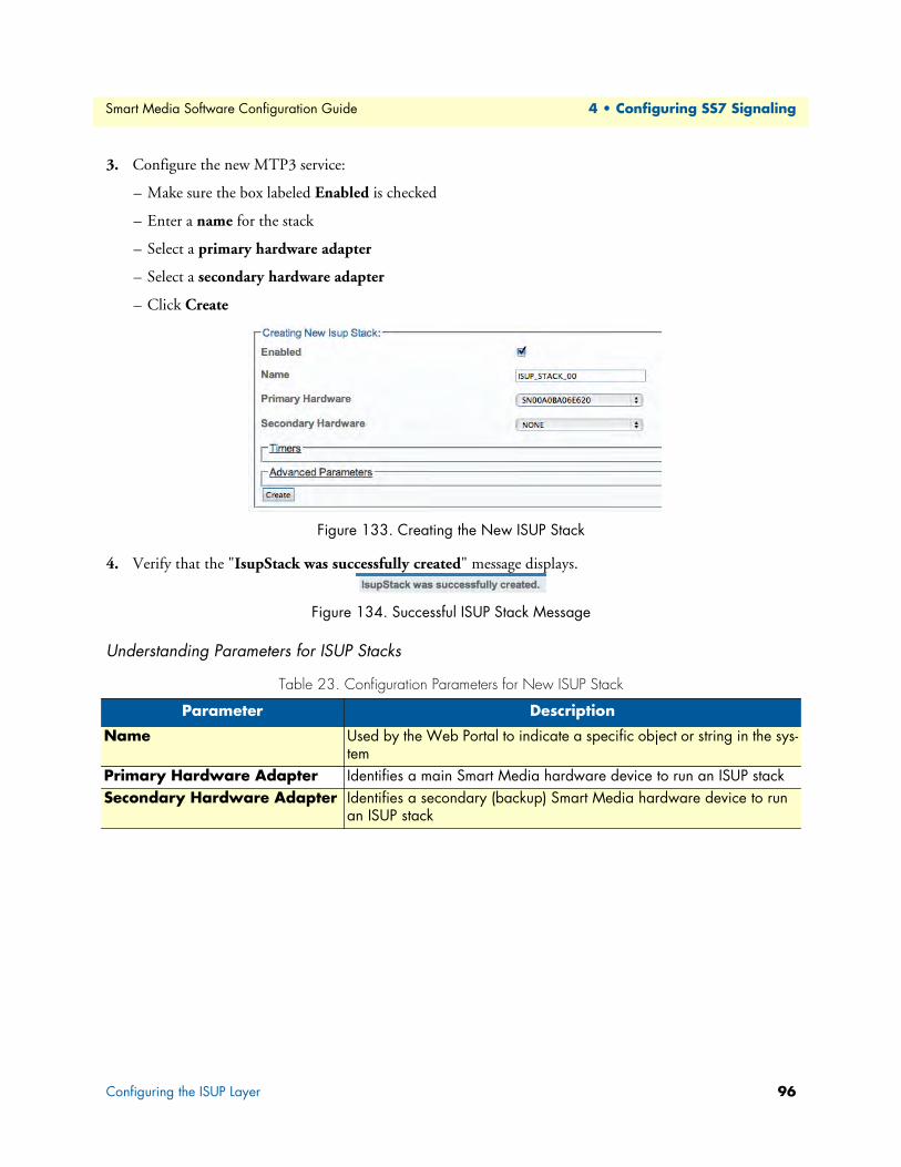
Smart Media Software Configuration Guide 4 • Configuring SS7 Signaling
3. Configure the new MTP3 service:
– Make sure the box labeled Enabled is checked
– Enter a name for the stack
– Select a primary hardware adapter
– Select a secondary hardware adapter
– Click Create
Figure 133. Creating the New ISUP Stack
4. Verify that the "IsupStack was successfully created" message displays.
Figure 134. Successful ISUP Stack Message
Understanding Parameters for ISUP Stacks
Table 23. Configuration Parameters for New ISUP Stack
Parameter Description
Name Used by the Web Portal to indicate a specific object or string in the sys-tem
Primary Hardware Adapter Identifies a main Smart Media hardware device to run an ISUP stackSecondary Hardware Adapter Identifies a secondary (backup) Smart Media hardware device to run
an ISUP stack
Configuring the ISUP Layer 96

Smart Media Software Configuration Guide 4 • Configuring SS7 Signaling
Creating an ISUP NetworkAfter you have created an initial ISUP stack, you must create a new ISUP network. The ISUP network tells the ISUP protocol layer about a collection of SS7 nodes that are accessible through MTP3 or M3UA. Based upon your system configuration, one or more ISUP networks are created. Repeat this section for as many networks as you require.
Note An ISUP network can be used by multiple ISUP interfaces even if they are members of different ISUP userpart (e.g., to support multi-ple switch variants for a single SS7 network).
To create an ISUP network:
1. Click "Create New ISUP Network" in the ISUP stack configuration window:
Figure 135. Editing ISUP Networks
2. Configure the new ISUP network:
– Enter a name for the network
– Select MTP3 or M3UA as the type of network to bind
– Select a MTP3 network or a M3UA network
– Click Create
Figure 136. Creating the New ISUP Network
3. Verify that the "IsupNetwork was successfully created" message displays.
Figure 137. Successful ISUP Network Message
Configuring the ISUP Layer 97

Smart Media Software Configuration Guide 4 • Configuring SS7 Signaling
Understanding Parameters for ISUP Networks
Creating an ISUP User PartAfter you have created your ISUP network, you must create a new ISUP user part. The user part is the con-tainer for the multiple ISUP interfaces. One user part is required for each protocol variant.
Multiple ISUP user parts can be instantiated within a single ISUP protocol layer. This allows a user application to interface with multiple SS7 ISUP protocol variants at the same time. Only one ISUP user part is required for a specific variant as it can be assigned to multiple ISUP networks.
A user part can easily be seen as a protocol variant that a host application wants to use on the SS7 network.
To create an ISUP user part:
1. Click Create New Isup Userpart in the ISUP stack configuration window:
Figure 138. Editing Userparts
2. Configure the new ISUP user part:
– Enter a name for the user part
– Select a protocol variant (depending on location)
– Select an MTP3 sub service field (the same that was previously set for MTP3)
– Select an address indicator type
– Select a Numbering Plan
Table 24. Configuration Parameters for New ISUP Network
Parameter Description
Name Used by the Web Portal to indicate a specific object or string in the systemType of Network to Bind Indicates the type of network to associate with an ISUP Network
Possible values: MTP3/M3UANetworksMTP3 Network Associates an MTP3 network with a higher level network in an SS7 systemM3UA Network Associates an MTP3 network with a higher level network in an SS7 system
Configuring the ISUP Layer 98

Smart Media Software Configuration Guide 4 • Configuring SS7 Signaling
– Click Create
Figure 139. Creating the New ISUP User Part
3. Verify that the "IsupUserpart was successfully created" message appears, and that the Enabled box is checked.
Figure 140. Successful ISUP User Part Message
Understanding Parameters for ISUP User Parts
Table 25. Configuration Parameters for New ISUP User Part
Parameter Description
Name Used by the Web Portal to indicate a specific object or string in the systemProtocol Type Identifies the SS7 protocol variant that will be used with a particular object. The
appropriate protocol variant depends on the user's geographical location. Values are chosen from a drop-down list. The Protocol Type parameter can take on the following values, depending on the object being configured:ITUITU88ITU92ITU97
TELCORDIAANSI88ANSI92ANSI95
SINGAPOREQ767TTCNTT
CHINAETSIETSIV3UK
Sub Service Field Differentiates between national and international signals in MTP3 networks. Possible values: International/National/Nat. Reserved/Inter. Reserved
Address Indicator Type Assigns a default address value in ISUP user parts, when unspecified. Possible values: Not Present/Subscriber Number/National Number/International Number
Numbering Plan Assigns a default numbering plan in ISUP user parts, when unspecified. Possible values:Unknown Telex
ISDN National
Telephony Private
Data Reserved
Configuring the ISUP Layer 99

Smart Media Software Configuration Guide 4 • Configuring SS7 Signaling
Creating an ISUP InterfaceAfter you have created an ISUP user part to contain them, you must create new ISUP interfaces.
The ISUP interface creates a binding within the ISUP layer of a particular variant, a specific network, and an OPC/DPC pair to which circuits can be assigned. The ISUP interface contains the circuit identifier codes (CICs) within the ISUP user part. One interface is created for each similar grouping of CICs within one user part protocol variant.
To create an ISUP interface:
1. Click Create New Isup Interface in the ISUP stack configuration window:
Figure 141. Editing ISUP Interfaces
2. Configure the new ISUP interface:
– Enter a name for the interface
– Select an ISUP user part
– Select an ISUP network
– Select a trunk type
– Select an originating point code (OPC)
– Select a destination point code (DPC)
– Click Create
Figure 142. Creating the New ISUP Interface
3. Verify that the "IsupInterface was successfully created" message displays.
Figure 143. Successful ISUP Interface Message
Configuring the ISUP Layer 100

Smart Media Software Configuration Guide 4 • Configuring SS7 Signaling
Understanding Parameters for ISUP Interfaces
Table 26. Configuration Parameters for New ISUP Interface
Parameter Description
Name Used by the Web Portal to indicate a specific object or string in the systemISUP User Part Associates an ISUP user part with an ISUP interfaceISUP Network Associates an ISUP network with an ISUP interfaceOPC Associates an object with an originating point code (OPC)DPC Associates an object with a destination point code (DPC)
Configuring the ISUP Layer 101

Smart Media Software Configuration Guide 4 • Configuring SS7 Signaling
Viewing the Status of SS7 MTP2 LinksGeneral and detailed status information about the SS7 MTP2 stack is accessible from the SS7 MTP2 tab of the Global Status view.
General ViewThe SS7 MTP2 general view provides information about the health of the MTP2 links. From this view you can know the status of MTP2 links by seeing if they are up or down. Selecting an active link will display the detailed view for that line.
Figure 144. General View: SS7 MTP2
Detailed View
MTP2 Link Detailed StatusThe MTP2 Link detailed status screen enables you to view the state of an MTP2 link and to modify the datalink state value for testing purposes.
To modify the datalink state of an MTP2 link:
1. Select a value from the Datalink state combo box.
2. Click 'Apply States' to change the state.
To reset the counters of this screen, do the following:
1. Select the 'Reset' status check box.
2. Click 'Now'.
Figure 145. Detailed View: MTP2 Link Status
Viewing the Status of SS7 MTP2 Links 102

Smart Media Software Configuration Guide 4 • Configuring SS7 Signaling
MTP2 Link ListingThe MTP2 Link listing, shown below, displays an expanded listing of each MTP2 link. In addition to indicat-ing whether a link is up or down, this listing provides supplemental information. Selecting an MTP2 link from this listing displays its detailed information. For a full listing of all MTP2 Links, select MTP2 from the naviga-tion panel, and choose the Status tab in the control panel.
Figure 146. Detailed View: MTP2 Link Listing
Viewing the Status of SS7 MTP2 Links 103

Smart Media Software Configuration Guide 4 • Configuring SS7 Signaling
Viewing the Status of SS7 MTP3 LinksGeneral and detailed status information about the SS7 MTP3 stack is accessible from the SS7 MTP3 tab of the Global Status view.
General ViewThe SS7 MTP3 general view, shown below, provides information about the health of the MTP3 links. From this view you can know the status of MTP3 links by seeing if they are up or down. This general view provides links to other detailed status screens for the MTP3 configuration, its links, linksets, and routes.
Figure 147. General View: SS7 MTP3
Detailed ViewThe SS7 MTP3 detailed view groups status information into four screens, as follows:
• “MTP3 Stack Status” on page 105
• “MTP3 Linkset” on page 105
• “MTP3 Link” on page 107
Viewing the Status of SS7 MTP3 Links 104

Smart Media Software Configuration Guide 4 • Configuring SS7 Signaling
MTP3 Stack StatusThe MTP3 Stack Status, shown below, displays counters for a variety of status messages that in turn are used to indicate the current health of the MTP3 stack. This status screen is accessed from the MTP3 CFG 0 link of the General view, shown in the figure above. Counters may be reset from this screen to determine if a problem per-sists.
To reset the counters of this screen:
1. Select the 'Reset status' check box.
2. Click 'Now'.
Figure 148. Detailed View: MTP3 Stack Status
MTP3 LinksetThe Linksets status screen, accessible from a linkset link shown in MTP3 Network Status: Linksets Tab, groups status information under two tabs as follows:
• Linksets
• Links
MTP3 Linkset Status: Linksets Tab. The Linkset tab of the MTP3 Network status screen, shown below, dis-plays the detailed information of one MTP3 linkset, such as linkset state, configured values, and counters. From this screen the desired linkset state may be set to Active or Inactive, and counters may be reset.
To reset the counters of this screen:
1. Select the 'Reset status' check box.
2. Click 'Now'.
To modify the Desired Linkset state:
1. Select a linkset state.
2. Click Apply States.
Viewing the Status of SS7 MTP3 Links 105

Smart Media Software Configuration Guide 4 • Configuring SS7 Signaling
Figure 149. Detailed View: MTP3 Linkset Status-Linkset Tab
MTP3 Linkset Status: Links Tab. The Links tab of the MTP3 Network status screen, shown below, displays a listing of the MTP3 links that are used by a specific MTP3 Linkset. In the listing, the status of each link is displayed as well as a link congestion timer. Accessing a particular MTP3 Link displays its detailed informa-tion.
Figure 150. Detailed View: MTP3 Linkset Status-Links Tab
Viewing the Status of SS7 MTP3 Links 106

Smart Media Software Configuration Guide 4 • Configuring SS7 Signaling
MTP3 LinkThe MTP3 Link status screen, shown below, displays the detailed information about one MTP3 link, such as the link state, configured values, and counters. Hovering over fields causes help bubbles to display. For exam-ple, in the figure below, an information bubble is displayed for a counter of the number of invalid Protocol Data Units (PDUs) received.
To reset the counters of this screen:
1. Select the 'Reset status' check box.
2. Click 'Now'
To modify the Desired Locally Inhibited state:
1. Select a value.
2. Click 'Apply States'.
Figure 151. Detailed View: MTP3 Link Status
Viewing the Status of SS7 MTP3 Links 107

Smart Media Software Configuration Guide 4 • Configuring SS7 Signaling
Viewing the Status of SS7 ISUP StacksGeneral and detailed status information about the SS7 ISUP stack is accessible from the SS7 ISUP tab of the Global Status view.
General ViewThe SS7 ISUP general view, shown below, lists ISUP stacks and indicates which are active, in standby, or out of service (Oos). In addition, the SS7 ISUP general view lists ISUP interfaces and indicates which are available, congested, or unavailable. This general view provides links to detailed status views of the ISUP stacks and net-works.
Figure 152. General View: SS7 ISUP
Viewing the Status of SS7 ISUP Stacks 108

Smart Media Software Configuration Guide 4 • Configuring SS7 Signaling
Detailed ViewThe SS7 ISUP detailed view groups status information into these main screens:
• “ISUP Stack Status” on page 109
• “ISUP Interface Status” on page 110
• “Circuit Group Status” on page 111
ISUP Stack StatusThe ISUP Stack status screen groups status information about the ISUP Stack under two tabs, as follows:
• Stack Tab
• Interfaces Tab
ISUP Stack Status: Stack tab. The Stack tab of the ISUP Stack status screen provides the name of the pri-mary and optionally secondary Smart Media unit that hosts the ISUP stack and the status.
Figure 153. Detailed View: ISUP Stack Status-Stack Tab
ISUP Stack Status: Interfaces tab. The Interfaces tab of the ISUP Stack status screen lists the configured ISUP interfaces of the ISUP stack and provides the states of each network as well as their transmit and receive message counters. Selecting an ISUP Interface link displays its detailed information.
Figure 154. Detailed View: ISUP Stack Status-Interfaces Tab
Viewing the Status of SS7 ISUP Stacks 109

Smart Media Software Configuration Guide 4 • Configuring SS7 Signaling
ISUP Interface StatusThe ISUP Interface status screen groups status information about the interface under two tabs, as follows:
• Interface Tab
• Circuit Groups Tab
ISUP Interface Status: Interface Tab. The Interface tab of the MTP3 Network status screen, shown below, provides transmit and receive message counters for a specific ISUP interface.
Figure 155. Detailed View: ISUP Interface Status-Interface Tab
ISUP Interface Status: Circuit Groups Tab. The Circuit Groups tab of the ISUP Stack status screen, shown below, lists the configured circuits groups for a specific ISUP interface. In addition, this screen provides status and counters for each circuit group. Selecting a circuit group link displays its detailed information.
Figure 156. Detailed View: ISUP Interface Status-Circuit Groups Tab
Viewing the Status of SS7 ISUP Stacks 110

Smart Media Software Configuration Guide 4 • Configuring SS7 Signaling
Circuit Group StatusThe Circuit Group status screen displays detailed information for one circuit group, such as status counters and configured values. From this screen, the desired group state may be set to Unblocked, Blocked, or Default.
To modify the desired group state:
1. Select a value.
2. Click 'Apply States'.
Figure 157. Detailed View: Circuit Group Status
Table 27. Circuit Group Status Settings
Circuit Group State Description
Default Lets the system decide the state of the circuit or circuit group. For example, a trunk down will block the circuits.
Blocked Forces a local block condition. No calls can be made on these circuits even if the trunks are up. This function is useful for forcing calls on specific circuits by blocking other circuits in the system.
Unblocked Forces a local unblock condition. This will force the circuits to be unblocked, even if the trunks are down. To be used for testing only.
Viewing the Status of SS7 ISUP Stacks 111

Chapter 5 Configuring SIGTRAN Applications
Chapter contentsOverview .............................................................................................................................................................115
Configuring an M2PA System.............................................................................................................................116
Adding an Adapter ........................................................................................................................................117Understanding Parameters for Hardware Adapters ..................................................................................119
Creating Line Interfaces ................................................................................................................................119
Understanding Parameters for Line Interfaces .........................................................................................120Creating Line Services ...................................................................................................................................121
Understanding Parameters for Line Services ............................................................................................123
Creating the SCTP Configuration ................................................................................................................124Understanding Parameters for SCTP Configurations ..............................................................................124
Creating an M2PA Configuration .................................................................................................................125
Understanding Parameters for M2PA Configurations .............................................................................125Creating an M2PA SAP ................................................................................................................................126
Understanding Parameters for M2PA SAPs .............................................................................................127
Creating M2PA Links ...................................................................................................................................127Understanding Parameters for M2PA Links ............................................................................................128
Creating SS7 Point Codes .............................................................................................................................129
Understanding Parameters for SS7 Point Codes ......................................................................................130Creating an MTP3 Configuration .................................................................................................................131
Understanding Parameters for MTP3 Configurations .............................................................................132
Creating an MTP3 Network .........................................................................................................................132Understanding Parameters for MTP3 Networks .....................................................................................133
Creating an MTP3 Linkset ...........................................................................................................................133
Understanding Parameters for MTP3 Linksets ........................................................................................134Creating MTP3 Links (M2PA) .....................................................................................................................134
Understanding Parameters for MTP3 (M2PA) Links ..............................................................................136
Creating an MTP3 Route .............................................................................................................................136Understanding Parameters for MTP3 Routes ..........................................................................................138
Creating an ISUP Stack ................................................................................................................................138
Understanding Parameters for ISUP Stacks .............................................................................................139Creating an ISUP Network ...........................................................................................................................139
Understanding Parameters for ISUP Networks .......................................................................................140
Creating an ISUP User Part ..........................................................................................................................141Understanding Parameters for ISUP User Parts .......................................................................................142
Creating an ISUP Interface ...........................................................................................................................142
Understanding Parameters for ISUP Interfaces ........................................................................................143Creating ISUP CIC Groups ..........................................................................................................................144
Understanding Parameters for ISUP CIC Groups ...................................................................................145
Creating a NAP (SIGTRAN) ........................................................................................................................145
112
Smart Media Software Configuration Guide 5 • Configuring SIGTRAN Applications
Understanding Parameters for NAPs (SIGTRAN) ..................................................................................147
Configuring an M2UA System on a Signaling Gateway.......................................................................................148
Creating an MTP2 Configuration .................................................................................................................148Understanding Parameters for MTP2 Configurations .............................................................................149
Creating MTP2 Links ...................................................................................................................................149
Understanding Parameters for MTP2 Links ............................................................................................151Creating an M2UA Configuration ................................................................................................................151
Understanding Parameters for M2UA Configurations ............................................................................152
Creating an M2UA SAP ...............................................................................................................................152Understanding Parameters for M2UA SAPs ............................................................................................153
Creating an M2UA Cluster ...........................................................................................................................153
Understanding Parameters for M2UA Clusters .......................................................................................154
Creating M2UA Links ..................................................................................................................................154Understanding Parameters for M2UA Links ...........................................................................................155
Creating M2UA Peers ...................................................................................................................................156
Understanding Parameters for M2UA Peers ............................................................................................157Configuring an M2UA System on a Media Gateway Controller..........................................................................158
Creating MTP3 Links (M2UA) ....................................................................................................................159
Understanding Parameters for MTP3 (M2UA) Links .............................................................................159Configuring an IUA System on a Signaling Gateway...........................................................................................160
Creating an IUA Configuration ....................................................................................................................160
Understanding Parameters for IUA Configurations .................................................................................161Creating an IUA SAP ....................................................................................................................................161
Understanding Parameters for IUA SAPs ................................................................................................162
Creating an IUA Cluster ...............................................................................................................................162Understanding Parameters for IUA Clusters ............................................................................................163
Creating IUA Links ......................................................................................................................................163
Understanding Parameters for IUA Links ................................................................................................164Creating IUA Peers .......................................................................................................................................164
Understanding Parameters for IUA Peers ................................................................................................165
Configuring an M3UA System on IP Signaling Points ........................................................................................166Creating an M3UA Configuration (IPSP) .....................................................................................................167
Understanding Parameters for M3UA Configurations ............................................................................167
Creating an M3UA SAP ...............................................................................................................................168Understanding Parameters for M3UA SAPs ............................................................................................169
Creating an M3UA Network ........................................................................................................................169
Understanding Parameters for M3UA Networks .....................................................................................170Creating an M3UA User Part .......................................................................................................................170
Understanding Parameters for M3UA User Parts ....................................................................................171
Creating an M3UA Peer Signaling Process (IPSP) ........................................................................................171Understanding Parameters for M3UA PSPs ............................................................................................172
Creating an M3UA Peer Server .....................................................................................................................173
Understanding Parameters for M3UA Peer Servers .................................................................................174Creating an M3UA Route .............................................................................................................................175
113

Smart Media Software Configuration Guide 5 • Configuring SIGTRAN Applications
Understanding Parameters for M3UA Routes .........................................................................................176
Configuring an M3UA System on a Signaling Gateway.......................................................................................177
Creating MTP3 Links (M3UA) ....................................................................................................................178Understanding Parameters for MTP3 (M3UA) Links .............................................................................179
Creating an M3UA Configuration (SGP) .....................................................................................................180
Understanding Parameters for M3UA Configurations ............................................................................180Creating an M3UA Peer Signaling Process (SGP) .........................................................................................181
Understanding Parameters for M3UA PSPs ............................................................................................182
Creating an M3UA Route (SGP) ..................................................................................................................183Understanding Parameters for M3UA Routes .........................................................................................184
Configuring an M3UA System on an Application Server.....................................................................................185
Creating an M3UA Configuration (ASP) ......................................................................................................186
Understanding Parameters for M3UA Configurations ............................................................................186Creating an M3UA Peer Signaling Process (ASP) .........................................................................................187
Understanding Parameters for M3UA PSPs ............................................................................................188
Creating an M3UA ISUP Network ...............................................................................................................189Understanding Parameters for M3UA ISUP Networks ...........................................................................190
114

Smart Media Software Configuration Guide 5 • Configuring SIGTRAN Applications
OverviewThe Smart Media system enables you to configure SIGTRAN and extend SS7 signaling functionality to the IP network. Smart Media enables you to configure a number of SIGTRAN applications based upon your require-ments. Refer to the following sections for configuring SIGTRAN applications:
• M2PA System: See “Configuring an M2PA System” on page 116. In this configuration, the SS7 MTP2 layer is replaced by the SIGTRAN M2PA layer which extends MTP2 signalling functionality into the IP network. This application is typically used between a Signalling Gateway and an IP Signalling Point, or between two IP Signalling Points.
• M2UA System: See “Configuring an M2UA System on a Signaling Gateway” on page 148, and “Configur-ing an M2UA System on a Media Gateway Controller” on page 158. An M2UA system on a Signalling Gateway Controller interfaces with an M2UA system on a Media Gate-way Controller. In this configuration, M2UA bridges the SS7 MTP2 layer of a Signalling Gateway, across an IP network, with the SS7 MTP3 layer of a Media Gateway Controller.
• IUA System: See “Configuring an IUA System on a Signaling Gateway” on page 160. An IUA system on a Signalling Gateway Controller interfaces with an IUA system on a Media Gateway Controller. In this configuration, IUA bridges the SS7 MTP2 layer of a Signalling Gateway, across an IP network, with the SS7 MTP3 layer of a Media Gateway Controller.
• M3UA System on two IP signaling points: See “Configuring an M3UA System on IP Signaling Points” on page 166. In this configuration, the SS7 MTP2 and MTP3 layers are replaced entirely by the SIGTRAN M3UA layer. This application is typically used between two IP Signalling Points.
• M3UA System: See “Configuring an M3UA System on a Signaling Gateway” on page 177, and “Configur-ing an M3UA System on an Application Server” on page 185. An M3UA system on a Signalling Gateway Process interfaces with an M3UA system on an Application Server Process. In this configuration, the MTP3 links are extended across the IP network.
Overview 115

Smart Media Software Configuration Guide 5 • Configuring SIGTRAN Applications
Configuring an M2PA SystemIn this configuration, the SS7 MTP2 layer is replaced by the SIGTRAN M2PA layer which extends MTP2 sig-nalling functionality into the IP network. This application is typically used between a Signaling Gateway and an IP Signaling Point, or between two IP Signaling Points. Refer to the following sections to configure an M2PA system:
1. “Adding an Adapter” on page 117
2. “Creating Line Interfaces” on page 119
3. “Creating Line Services” on page 121
4. “Creating the SCTP Configuration” on page 124
5. “Creating an M2PA Configuration” on page 125
– “Creating an M2PA SAP” on page 126
– “Creating M2PA Links” on page 127
6. “Creating SS7 Point Codes” on page 129
7. “Creating an MTP3 Configuration” on page 131
– “Creating an MTP3 Network” on page 132
– “Creating an MTP3 Linkset” on page 133
– “Creating MTP3 Links (M2PA)” on page 134
– “Creating an MTP3 Route” on page 136
8. “Creating an ISUP Stack” on page 138
– “Creating an ISUP Network” on page 139
– “Creating an ISUP User Part” on page 141
– “Creating an ISUP Interface” on page 142
– “Creating ISUP CIC Groups” on page 144
– “Creating a NAP (SIGTRAN)” on page 145
Configuring an M2PA System 116

Smart Media Software Configuration Guide 5 • Configuring SIGTRAN Applications
Adding an AdapterWhen you receive a new system, at least one hardware configuration will have been set in the Smart Media application server, by default. To add other hardware devices, you must use the Smart Media Web Portal. To add one or more additional hardware devices to the Smart Media system configuration, their serial numbers must be registered with the Smart Media application server.
To add a hardware device:
1. Select Hardware from the navigation panel:
Figure 158. config_patton > Hardware
2. Click Create New Hardware to add a new hardware device:
Figure 159. Hardware List
3. Configure the new adapter:
– Enter a name for the hardware device
– Enter the serial number of the new hardware device (filling in the Serial Number field will cause auto-completion of the field to occur).
– Select the appropriate hardware device from the Adapter Type field.
– Select Enabled from the Target State field.
Configuring an M2PA System 117

Smart Media Software Configuration Guide 5 • Configuring SIGTRAN Applications
– Click Create
Figure 160. Creating the New Hardware Device
4. Verify that the "Adapter was successfully created" message displays, and that the newly added hardware device appears in the Hardware List below.
Figure 161. Successful Device Message
Configuring an M2PA System 118

Smart Media Software Configuration Guide 5 • Configuring SIGTRAN Applications
Understanding Parameters for Hardware Adapters
Creating Line InterfacesLine interface is a generic term for TDM physical interfaces. The SmartNode 10200 Series supports three types of physical interfaces: T1/E1/J1 interfaces, DS3 interfaces, and Oc3/STM1 interfaces.
To create a new line interface:
1. Select Tdm Interfaces-->Line Interfaces from the navigation panel:
Figure 162. TDM Interfaces > Line Interfaces
2. Click Create New Line Interface to create a single interface, or Create Multiple Line Interfaces to create many interfaces at once:
Figure 163. Line Interface List
3. Create the new line interface:
– Enter a name for the interface
– Set a type for the interface
Table 28. Configuration Parameters for New Hardware Adapters
Parameter Description
Name Used by the Web Portal to indicate a specific object or string in the systemSerial Defines a product serial number, when creating a new hardware device. Enter-
ing characters into the Serial field will cause the number to auto-complete.Adapter Type Specifies the type of hardware device being created, when adding a new
adapter. Possible values: TMP/TMSGraceful Upgrade Timeout
Sets a maximal delay for calls to terminate normally before an adapter is upgraded
Location Identifies the physical location of a hardware adapterDescription Describes the purpose of a particular hardware adapterTarget State Sets the live state of a hardware adapter. Possible values:
Disabled/Probation/Enabled
Configuring an M2PA System 119

Smart Media Software Configuration Guide 5 • Configuring SIGTRAN Applications
– Set a local index for the line
– Select a length and an encoding scheme
– Click Create
Figure 164. Create New Line Interface
4. Verify that the "Line interface was successfully created" message is displayed.
Figure 165. Confirmation Message for New Line Interface
Understanding Parameters for Line Interfaces
Table 29. Configuration Parameters for New Line Interfaces
Parameter Description
Name Used by the Web Portal to indicate a specific object or string in the systemType Defines the type of line interface: E1/DS3/T1/J1/STM1/OC3Local Index Assigns an integer to represent an objectLength Indicates the physical length of a line: Short/Long/Autodetect/MonitoringEncoding Sets an encoding scheme for a line interface. Values depend on the interface type:
E1: DS3:
T1/J1:STM1/OC3:
HDB3/AMIB3ZSB8ZS/AMI/AMI CLEAR(None)
Configuring an M2PA System 120

Smart Media Software Configuration Guide 5 • Configuring SIGTRAN Applications
Creating Line ServicesYou must create a new line service for your line interface. A line service defines the payload type of a line inter-face or another line service. The line service chain stops when it reach the E1/J1/T1 line service. The E1/J1/T1 line services are also known as trunks or spans.
To create a new line service:
1. Select Tdm Interfaces-->Line Interfaces from the navigation panel:
Figure 166. TDM Interfaces > Line Interfaces
2. Click Edit next to the line service for which you wish to create a line service:
Figure 167. Line Interface List
3. In the following window, click Create New Child Line Service (also, a number can be created at once by selecting Create Multiple Child Line Service):
Figure 168. Editing a Line Interface to Create a New Service
4. Create the new line service:
– Enter a name for the new line
– Select an available local index, from the drop-down box
– Select appropriate framing and loopback modes
Configuring an M2PA System 121

Smart Media Software Configuration Guide 5 • Configuring SIGTRAN Applications
– Click Create
Figure 169. Create New Line Service
5. Navigate back to the line interface page, by following link displayed in the upper-left corner of the screen. The new line service should be displayed in the Line Services list.
Figure 170. Line Services List
Configuring an M2PA System 122

Smart Media Software Configuration Guide 5 • Configuring SIGTRAN Applications
Understanding Parameters for Line Services
Table 30. Configuration Parameters for New Line Services
Parameter Description
Name Used by the Web Portal to indicate a specific object or string in the systemLocal Index Assigns an integer to represent an objectFraming Sets a framing type for a line service. Select from:
AUTO (typical for E1)/STD/MFRAME/SF/ESF (typical for T1)/SLC96Loopback Used to set a loopback state for a line service. Refer to Table 31 for details.
Table 31. Loopback Types
Loopback Type Description Behavior Use
NONE Normal Operation
All traffic is received and sent on the line Always
LINE Analog Line Loopback
All received traffic is re-routed on the transmit line. The clock and data recovered from the line inputs are routed back to the line outputs of the analog transceiver bypassing the framer modules.
First step in testing a physical connection
PAYLOAD Digital Line Loopback
All received traffic is re-routed on the transmit line.The clock and data recovered from the line inputs are routed back to the line outputs after the deframer/framer.
Second step in testing a physical connection. This tests the framer configuration.
GENERATE_LOS Generate Loss of Signal
This forces the transmit line to stop sending. This is the second-best thing to disconnecting the line interface physi-cally.
LOCAL Local Loopback All received traffic is dropped. The traffic sent is re-routed internally.
Never. Used for inter-nal testing only
Configuring an M2PA System 123

Smart Media Software Configuration Guide 5 • Configuring SIGTRAN Applications
Creating the SCTP ConfigurationStream Control Transmission Protocol (SCTP), a Transport Layer protocol, ensures reliable, in-sequence transport of messages. To edit your system's SCTP configuration:
1. Select SCTP from the navigation panel:
Figure 171. Signaling > SCTP
2. Configure the new SCTP service:
– Make sure the box labeled Enabled is checked
– Enter a name for the SCTP service
– Select an appropriate service type: RAW_IP or UDP
– Click Create
Figure 172. Creating a New MTP2 Link
3. Verify that the "Sctp Cfg was successfully created" message displays:
Figure 173. Successful SCTP Configuration Message
Understanding Parameters for SCTP Configurations
Table 32. Configuration Parameters for New SCTP Configurations
Parameter Description
Name Used by the Web Portal to indicate a specific object or string in the systemService Type Defines the purpose of an SCTP configuration. Possible values:
RAW IP: Enables the direct transmission and reception of network packets by applications, bypassing all encapsulation in the networking software of the operating system.
UDP: Provides a direct way to send and receive datagrams over IP networks.
Configuring an M2PA System 124

Smart Media Software Configuration Guide 5 • Configuring SIGTRAN Applications
Creating an M2PA ConfigurationFor the configuration of your SIGTRAN M2PA system, you will need to create a new M2PA configuration. In this system, the SS7 MTP2 layer is replaced by the SIGTRAN M2PA layer which extends MTP2 signaling functionality into the IP network.
Note M2PA replaces the MTP2 layer entirely; however, it still requires the MTP3 layer.
To create an M2PA configuration:
1. Select M2PA from the navigation panel:
Figure 174. Signaling > M2PA
2. Configure the new M2PA service:
– Verify that the Enabled box is checked
– Enter a name for the M2PA configuration
– Click Create
Figure 175. Creating the New M2PA Configuration
3. Verify that the "M2pa Cfg was successfully created" message displays.
Figure 176. Successful M2PA Configuration Message
Understanding Parameters for M2PA Configurations
Table 33. Configuration Parameters for New M2PA Configurations
Parameter Description
Enabled Indicates whether or not an object is to be implemented or notName Used by the Web Portal to indicate a specific object or string in the system
Configuring an M2PA System 125

Smart Media Software Configuration Guide 5 • Configuring SIGTRAN Applications
Creating an M2PA SAPAfter you have created an M2PA configuration, you must create a new M2PA service access point (SAP) for your system. The SAP is an identifying label for endpoints in your network.
To create a new M2PA SAP:
1. Select M2PA from the navigation panel (Figure 174 on page 125).
2. Click Create new M2pa Sap:
Figure 177. M2PA SAPs
3. Configure the new M2PA SAP:
– Enter a name for the SAP
– Enter an SCTP source port for the SAP
– Click Create
Figure 178. Creating the New M2PA SAP
4. Verify that the "M2pa Cfg was successfully created" message displays.
Figure 179. Successful M2PA Configuration Message
5. Associate IP interfaces:
– Select an IP interface from the list in the information panel
– Click the "<<" button to add the selected IP interface. This is the outgoing route from the hardware adapter.
Figure 180. Associating IP Interfaces
Configuring an M2PA System 126

Smart Media Software Configuration Guide 5 • Configuring SIGTRAN Applications
Understanding Parameters for M2PA SAPs
Creating M2PA LinksAfter you have created an M2PA service access point (SAP), you must create a new M2PA link. This can be done from the M2PA SAP configuration window.
To create an M2PA link:
1. Click Create new M2pa link in the M2PA SAP configuration window:
Figure 181. M2PA Links
2. Configure the new M2PA link:
– Enter a name for the new link
– Select a protocol type: ITU / ANSI / TTC
– Set other features, as needed: Number of SCTP Streams / IP Header TOS / Destination port (same value as the one configured on the destination side)
– Click Create
Figure 182. Creating a New M2PA Link
Table 34. Configuration Parameters for New M2PA SAP
Parameter Description
Name Used by the Web Portal to indicate a specific object or string in the systemSCTP Source Port Defines a source port for a service access point (SAP) in a system using SIGTRAN
protocols
Configuring an M2PA System 127

Smart Media Software Configuration Guide 5 • Configuring SIGTRAN Applications
3. Enter a destination address in the appropriate box in the information panel:
– Click the "<<" button to add the destination address to the address list
Figure 183. Designating a Destination Address
4. Verify that the address has been added to the list, and that the "(your address) was successfully added" message displays (ex.: here the address is 190.0.0.0):
Figure 184. Successful M2PA Link Message
Understanding Parameters for M2PA Links
Table 35. Configuration Parameters for New M2PA Links
Parameter Description
Name Used by the Web Portal to indicate a specific object or string in the systemProtocol Type Identifies the SS7 protocol variant that will be used with a particular object.
The appropriate protocol variant depends on the user's geographical loca-tion. Values are chosen from a drop-down list. The Protocol Type parameter can take on the following values, depending on the object being config-ured:ITUITU88ITU92ITU97
TELCORDIAANSI88ANSI92ANSI95
SINGAPOREQ767TTCNTT
CHINAETSIETSIV3UK
Number of SCTP Streams Sets the number of streams on a link in a system using the SCTP protocolIP Header TOS Assigns a Type of Service (TOS) value to a lineDestination Port Sets a destination for a line in a system using SIGTRAN protocols
Configuring an M2PA System 128

Smart Media Software Configuration Guide 5 • Configuring SIGTRAN Applications
Creating SS7 Point CodesPoint codes are used to define the Smart Media system network, the adjacent network and the target network so that calls are properly routed from one network to the next.
To create SS7 originating (OPC) and destination (DPC) point codes:
1. Select Point Codes from the navigation panel:
Figure 185. SS7 > Point Codes
2. Click Create New Point Code:
Figure 186. Point Codes
3. Configure the new point code:
– Enter a name for the point code
– Select a point code type (select type-specific parameters)
– Select a point code length (14, 16, 24 bits)
– Enter a point code
– Click Create
Figure 187. Creating the New MTP3 Point Code
Configuring an M2PA System 129

Smart Media Software Configuration Guide 5 • Configuring SIGTRAN Applications
4. Verify that the "Mtp3PointCode was successfully created" message displays, and the new point code appears in the Point Codes list:
Figure 188. Successful Point Code Message
Understanding Parameters for SS7 Point Codes
Table 36. Configuration Parameters for New Point Codes
Parameter Description
Name Used by the Web Portal to indicate a specific object or string in the systemType Defines the type of point code being created. Possible values: OPC/DPC/MaskDPC Length Sets a format for the Destination Point Code (DPC) used by an object.
Possible values: 14bits format=3.8.3/16bits format=7.4.5/24bits format=8.8.8Point Code Defines a point code by assigning it numerical values.
Configuring an M2PA System 130

Smart Media Software Configuration Guide 5 • Configuring SIGTRAN Applications
Creating an MTP3 ConfigurationMTP3 provides message routing between signaling points in an SS7 network.
To create an MTP3 configuration:
1. Select MTP3 from the navigation panel:
Figure 189. SS7 > MTP3
2. Configure the new MTP3 service:
– Enter a name for the MTP3 configuration
– Make sure the Enabled and SSf Validation boxes are checked
– Select SP as the signaling point type
– Select a restart procedure
– Click Create
Figure 190. Creating the New MTP3 Configuration
3. Verify that the "Mtp3Cfg was successfully created" message appears, and that the Enabled box is checked.
Figure 191. Successful Configuration Message
Configuring an M2PA System 131

Smart Media Software Configuration Guide 5 • Configuring SIGTRAN Applications
Understanding Parameters for MTP3 Configurations
Creating an MTP3 NetworkAfter you have created your system's MTP3 configuration, you must create a new MTP3 network. An MTP3 network is created to define its point codes, link sets and routes. This can be done from the MTP3 configura-tion information panel.
To create an MTP3 network:
1. Click Create New MTP3 Network in the MTP3 configuration information panel:
Figure 192. MTP3 Networks in MTP3 Configuration Window
2. Configure the settings for the new network:
– Enter a name for the network
– Select a sub service field
– Select a link type
– Select the SS7 DPC length
– Click Create
Figure 193. Creating a New MTP3 Network
3. Verify that the "MTP3 network was successfully created" message displays:
Figure 194. Successful Network Message
Table 37. Configuration Parameters for New MTP3 Configurations
Parameter Description
Name Used by the Web Portal to indicate a specific object or string in the systemEnabled Indicates whether or not an object is to be implemented or notSsf Validation Allows the activation of sub-service field validation for an MTP3 configurationSignaling Point Type Indicates the intended purpose of an SS7 MTP3 layer object. Possible values:
SP (Signaling Point)/STP (Signal Transfer Point)Restart Procedure Indicates the standard by which a configuration will carry out a restart process.
Possible values: None/ITU88/ITU92/ANSI
Configuring an M2PA System 132

Smart Media Software Configuration Guide 5 • Configuring SIGTRAN Applications
Understanding Parameters for MTP3 Networks
Creating an MTP3 LinksetAfter you have created an MTP3 network, you are ready to create an MTP3 linkset. This can be done through the MTP3 network configuration window. A linkset is used to logically combine multiple MTP3 links going to the same DPC into a single entity. One linkset could be the links between a point code identifying the Smart Media SS7 node and a point code identifying the adjacent SS7 equipment.
To create an MTP3 linkset:
1. Click Create New Mtp3 Linkset in the MTP3 Network configuration panel:
Figure 195. MTP3 Linksets
2. Configure the new linkset:
– Enter a name for the linkset
– Select an origin point code (OPC)
– Select an adjacent point code
– Make sure the desired state is set to Active
Table 38. Configuration Parameters for New MTP3 Networks
Parameter Description
Name Used by the Web Portal to indicate a specific object or string in the systemSub Service Field Differentiates between national and international signals in MTP3 networks.
Possible values: International/National/Nat. Reserved/Inter. ReservedLink Type Sets a protocol type for signaling links. Possible values:
ANSI/ITU/CHINA/ANSI96SS7 DPC Length Sets a format for the Destination Point Code (DPC) used by an object.
Possible values: 14bits format=3.8.3/16bits format=7.4.5/24bits format=8.8.8
Configuring an M2PA System 133

Smart Media Software Configuration Guide 5 • Configuring SIGTRAN Applications
– Click Create
Figure 196. Creating the New MTP3 Linkset
3. Verify that the "Mtp3Linkset was successfully created" message displays:
Figure 197. Successful Linkset Message
Understanding Parameters for MTP3 Linksets
Creating MTP3 Links (M2PA)This can be done from the MTP3 linkset configuration window. A linkset is used to logically combine multi-ple MTP3 links going to the same DPC into a single entity. One linkset could be comprised of the links between a point code identifying the Smart Media SS7 node and a point code identifying the adjacent SS7 equipment.
To create an MTP3 link:
1. Click Create New Mtp3 Link in the MTP3 linkset configuration window:
Figure 198. M2PA Links
2. Configure the new MTP3 link:
– Enter a name for the link
Table 39. Configuration Parameters for New MTP3 Linksets
Parameter Description
Name Used by the Web Portal to indicate a specific object or string in the systemOrigin Point Code Associates an object with an originating point code (OPC)Adjacent Point Code Associates an object with an adjacent point codeDesired State Indicates whether an object is to be active or inactive upon creation
Possible values: Active/Inactive
Configuring an M2PA System 134

Smart Media Software Configuration Guide 5 • Configuring SIGTRAN Applications
– Under Type of link to bind, select M2PA
– Select an MTP2 link
– Select a priority level (from 0 to 3)
– Select a message priority (from "none" to 3)
– Set the C Link value
– Enter a Link Test Slc (this value is unique in the link list)
– Enter Link Test Characters
– Click Create
Figure 199. Creating the New MTP3 (M2PA) Link
3. Verify that the "Mtp3Link was successfully created" message displays:
Figure 200. Successful MTP3 Link Message
Configuring an M2PA System 135

Smart Media Software Configuration Guide 5 • Configuring SIGTRAN Applications
Understanding Parameters for MTP3 (M2PA) Links
Creating an MTP3 RouteMTP3 routes are built to route traffic from previously created point codes using linksets. One route is created for each previously defined point code.
To create an MTP3 route:
1. Click Create New Mtp3 Route in the MTP3 network configuration window::
Figure 201. MTP3 Routes
2. Configure the new MTP3 route:
– Enter a name for the route
– Select a point code for the route
– Select a restart procedure
– Select a point type
– Check the Route to Adjacent box, if this route is directed to an adjacent network
Table 40. Configuration Parameters for New MTP3 (M2PA) Links
Parameter Description
Name Used by the Web Portal to indicate a specific object or string in the systemType of Link to Bind Indicates the type of link to bind when creating an MTP3 link
Possible values: MTP2/M2PA/M2UAMTP2 Link Selects an MTP2 link to bind to an objectPriority Level Sets a priority for MTP3 links. Possible values:
Priority 0/Priority 1/Priority 2/Priority 3Message Priority Sets a priority for messages on an MTP3 link. Possible values:
None/Priority 0/Priority 1/Priority 2/Priority 3C Link Used only when two identical signal transfer points (STPs) are interconnectedLink Test Slc Used in SLTM/SLTA messages on MTP3 links. Possible values: 0-15
*NOTE: Both ends of the line must use the same value, or the line will fail.Link Test Characters Creates a test packet for MTP3 lines
Configuring an M2PA System 136

Smart Media Software Configuration Guide 5 • Configuring SIGTRAN Applications
– Create
Figure 202. Creating the New MTP3 Route
3. Verify that the "Mtp3Route was successfully created" message displays:
Figure 203. Successful MTP3 Route Message
4. Associate the newly created route with a linkset:
– Select a linkset from the list provided at the bottom of the route configuration window
– Click the "<<" button to associate the linkset with the newly created route
Figure 204. Associating Routes with Linksets
Configuring an M2PA System 137
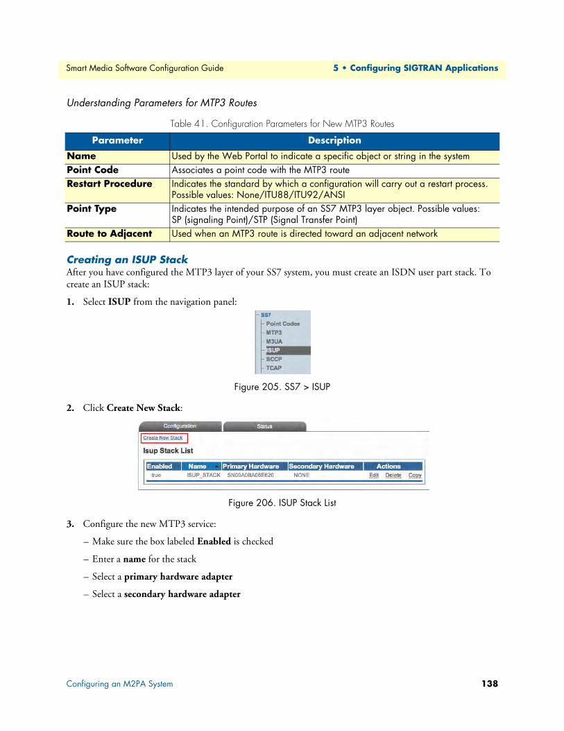
Smart Media Software Configuration Guide 5 • Configuring SIGTRAN Applications
Understanding Parameters for MTP3 Routes
Creating an ISUP StackAfter you have configured the MTP3 layer of your SS7 system, you must create an ISDN user part stack. To create an ISUP stack:
1. Select ISUP from the navigation panel:
Figure 205. SS7 > ISUP
2. Click Create New Stack:
Figure 206. ISUP Stack List
3. Configure the new MTP3 service:
– Make sure the box labeled Enabled is checked
– Enter a name for the stack
– Select a primary hardware adapter
– Select a secondary hardware adapter
Table 41. Configuration Parameters for New MTP3 Routes
Parameter Description
Name Used by the Web Portal to indicate a specific object or string in the systemPoint Code Associates a point code with the MTP3 routeRestart Procedure Indicates the standard by which a configuration will carry out a restart process.
Possible values: None/ITU88/ITU92/ANSIPoint Type Indicates the intended purpose of an SS7 MTP3 layer object. Possible values:
SP (signaling Point)/STP (Signal Transfer Point)Route to Adjacent Used when an MTP3 route is directed toward an adjacent network
Configuring an M2PA System 138

Smart Media Software Configuration Guide 5 • Configuring SIGTRAN Applications
– Click Create
Figure 207. Creating the New ISUP Stack
4. Verify that the "IsupStack was successfully created" message displays.
Figure 208. Successful ISUP Stack Message
Understanding Parameters for ISUP Stacks
Creating an ISUP NetworkAfter you have created an initial ISUP stack, you must create a new ISUP network. The ISUP network tells the ISUP protocol layer about a collection of SS7 nodes that are accessible through MTP3 or M3UA. Based upon your system configuration, one or more ISUP networks are created. Repeat this section for as many networks as you require.
Note An ISUP network can be used by multiple ISUP interfaces even if they are members of different ISUP userpart (e.g., to support multi-ple switch variants for a single SS7 network).
To create an ISUP network:
1. Click "Create New ISUP Network" in the ISUP stack configuration window:
Figure 209. Editing ISUP Networks
Table 42. Configuration Parameters for New ISUP Stack
Parameter Description
Name Used by the Web Portal to indicate a specific object or string in the sys-tem
Primary Hardware Adapter Identifies a main Smart Media hardware device to run an ISUP stackSecondary Hardware Adapter Identifies a secondary (backup) Smart Media hardware device to run
an ISUP stack
Configuring an M2PA System 139

Smart Media Software Configuration Guide 5 • Configuring SIGTRAN Applications
2. Configure the new ISUP network:
– Enter a name for the network
– Select MTP3 or M3UA as the type of network to bind
– Select a MTP3 network or a M3UA network
– Click Create
Figure 210. Creating the New ISUP Network
3. Verify that the "IsupNetwork was successfully created" message displays.
Figure 211. Successful ISUP Network Message
Understanding Parameters for ISUP Networks
Table 43. Configuration Parameters for New ISUP Network
Parameter Description
Name Used by the Web Portal to indicate a specific object or string in the systemType of Network to Bind Indicates the type of network to associate with an ISUP Network
Possible values: MTP3/M3UANetworksMTP3 Network Associates an MTP3 network with a higher level network in an SS7 systemM3UA Network Associates an MTP3 network with a higher level network in an SS7 system
Configuring an M2PA System 140

Smart Media Software Configuration Guide 5 • Configuring SIGTRAN Applications
Creating an ISUP User PartAfter you have created your ISUP network, you must create a new ISUP user part. The user part is the con-tainer for the multiple ISUP interfaces. One user part is required for each protocol variant.
Multiple ISUP user parts can be instantiated within a single ISUP protocol layer. This allows a user application to interface with multiple SS7 ISUP protocol variants at the same time. Only one ISUP user part is required for a specific variant as it can be assigned to multiple ISUP networks.
A user part can easily be seen as a protocol variant that a host application wants to use on the SS7 network.
To create an ISUP user part:
1. Click Create New Isup Userpart in the ISUP stack configuration window:
Figure 212. Editing Userparts
2. Configure the new ISUP user part:
– Enter a name for the user part
– Select a protocol variant (depending on location)
– Select an MTP3 sub service field (the same that was previously set for MTP3)
– Select an address indicator type
– Select a Numbering Plan
– Click Create
Figure 213. Creating the New ISUP User Part
3. Verify that the "IsupUserpart was successfully created" message appears, and that the Enabled box is checked.
Figure 214. Successful ISUP User Part Message
Configuring an M2PA System 141

Smart Media Software Configuration Guide 5 • Configuring SIGTRAN Applications
Understanding Parameters for ISUP User Parts
Creating an ISUP InterfaceAfter you have created an ISUP user part to contain them, you must create new ISUP interfaces.
The ISUP interface creates a binding within the ISUP layer of a particular variant, a specific network, and an OPC/DPC pair to which circuits can be assigned. The ISUP interface contains the circuit identifier codes (CICs) within the ISUP user part. One interface is created for each similar grouping of CICs within one user part protocol variant.
To create an ISUP interface:
1. Click Create New Isup Interface in the ISUP stack configuration window:
Figure 215. Editing ISUP Interfaces
Table 44. Configuration Parameters for New ISUP User Part
Parameter Description
Name Used by the Web Portal to indicate a specific object or string in the systemProtocol Type Identifies the SS7 protocol variant that will be used with a particular object. The
appropriate protocol variant depends on the user's geographical location. Values are chosen from a drop-down list. The Protocol Type parameter can take on the following values, depending on the object being configured:ITUITU88ITU92ITU97
TELCORDIAANSI88ANSI92ANSI95
SINGAPOREQ767TTCNTT
CHINAETSIETSIV3UK
Sub Service Field Differentiates between national and international signals in MTP3 networks. Possible values: International/National/Nat. Reserved/Inter. Reserved
Address Indicator Type Assigns a default address value in ISUP user parts, when unspecified. Possible values: Not Present/Subscriber Number/National Number/International Number
Numbering Plan Assigns a default numbering plan in ISUP user parts, when unspecified. Possible values:Unknown Telex
ISDN National
Telephony Private
Data Reserved
Configuring an M2PA System 142

Smart Media Software Configuration Guide 5 • Configuring SIGTRAN Applications
2. Configure the new ISUP interface:
– Enter a name for the interface
– Select an ISUP user part
– Select an ISUP network
– Select a trunk type
– Select an originating point code (OPC)
– Select a destination point code (DPC)
– Click Create
Figure 216. Creating the New ISUP Interface
3. Verify that the "IsupInterface was successfully created" message displays.
Figure 217. Successful ISUP Interface Message
Understanding Parameters for ISUP Interfaces
Table 45. Configuration Parameters for New ISUP Interface
Parameter Description
Name Used by the Web Portal to indicate a specific object or string in the systemISUP User Part Associates an ISUP user part with an ISUP interfaceISUP Network Associates an ISUP network with an ISUP interfaceOPC Associates an object with an originating point code (OPC)DPC Associates an object with a destination point code (DPC)
Configuring an M2PA System 143

Smart Media Software Configuration Guide 5 • Configuring SIGTRAN Applications
Creating ISUP CIC GroupsAfter you have created an ISUP interface, you must create a new ISUP Cicuit Identification Code (CIC) group for your system.A CIC represents a physical timeslot between two SS7 nodes. Both of those nodes must com-monly agree upon a CIC numbering scheme.
To create an ISUP CIC group:
1. Click Create New Isup Cic Group in the ISUP interface configuration window (a number of groups can be created at once by clicking Create Multiple New Isup Cic Group):
Figure 218. Editing CIC Groups
2. Configure the new ISUP CIC group:
– Enter a name for the group
– Enter a number for the first CIC in the group (this value must follow other CIC group values, and not overlap)
– Select a line service
– Check the appropriate timeslots (click "Select all" to check all timeslots)
– Select a call control method
– Click Create
Figure 219. Creating the New ISUP CIC Group
3. Verify that the "IsupCicGroup was successfully created" message displays.
Figure 220. Successful ISUP CIC Group Message
Configuring an M2PA System 144

Smart Media Software Configuration Guide 5 • Configuring SIGTRAN Applications
Understanding Parameters for ISUP CIC Groups
Creating a NAP (SIGTRAN)After you have created an ISUP CIC group, you must create a network access point, in order to finish config-uring your system. A Network Access Point (NAP) represents the entry point to another network or destina-tion peer.
To create a network access point (NAP):
1. Click NAP in the navigation panel:
Figure 221. Menu: NAP
2. Click Create New NAP:
Figure 222. Edit NAP List
3. Configure the new NAP:
– Enter a name for the NAP
– Select a user-created profile, if not, select default
Table 46. Configuration Parameters for New ISUP CIC Group
Parameter Description
Name Used by the Web Portal to indicate a specific object or string in the systemFirst CIC Sets a value for the first circuit identification code in an ISUP CIC groupLine Service Indicates which TDM line service is to be associated with the object being cre-
atedTimeslots Allows the selection of individual voice or data channels of a line. Values for
this parameter are listed as check boxes (ranging from 1-24). Individual timeslots can be selected by checking the boxes. Occasionally, all timeslots can be selected at once by clicking the Select All link.
Call Control Sets a call control method for ISUP CIC groups. Possible values:Incoming/Outgoing/Bothway/Controlled/Controlling
Configuring an M2PA System 145

Smart Media Software Configuration Guide 5 • Configuring SIGTRAN Applications
– Click Create:
Figure 223. Creating a New NAP (SIGTRAN)
4. Verify that the NAP was successfully created message appears:
Figure 224. Confirmation Message for New NAP
5. Associate an ISUP interface with the new NAP:
– Select an interface (the newly-created ISUP CIC group)
– Click the "<<" button to associate it with the NAP
Figure 225. Associating ISUP CIC Groups with NAPs
The following screen displays:
Figure 226. Saving the New NAP SS7 Parameters
– Select a value for Channel Usage to avoid call collision.
– Click Save
Configuring an M2PA System 146

Smart Media Software Configuration Guide 5 • Configuring SIGTRAN Applications
6. Verify that the NAP was successfully updated message displays:
Figure 227. Confirmation Message for Updated NAP
Understanding Parameters for NAPs (SIGTRAN)
Table 47. Configuration Parameters for NAPs (SIGTRAN)
Parameter Description
Name Used by the Web Portal to indicate a specific object or string in the systemDefault Profile Sets a profile for a NAP. The default value is simply labeled "Default", but can be
changed if alternate profiles have been created.Channel Usage Sets a channel usage scheme for Network Access Points (NAPs), also called trunk
groups, in order to avoid call collision. Possible values:Round-Robin: Traverse, in order, all timeslots of the NAP from first timeslot of
first trunk to last timeslot of last trunk, before starting to use first timeslot of first trunk again.
Lowest Timeslot: Start from lowest timeslot of every trunk and will reuse them if they are idle.
Highest Timeslot: Start from highest timeslot of every trunk and will reuse them if they are idle.
Lowest Mapping ID: Start from lowest timeslot of first trunk, second lowest of first trunk, etc. Once the first trunk is full, will start using second trunk. Will reuse the channels if they are idle.
Highest Mapping ID: Start from highest timeslot of last trunk, second highest of last trunk, etc. Once the last trunk is full, will start using second-to-last trun. Will reuse the channels if they are idle.
Lowest CIC: Start from lowest CIC value of the NAP and will reuse them if they are idle.
Highest CIC: Start from highest CIC value of the NAP and will reuse them if they are idle.
Odd Lowest CIC: Start from lowest CIC, odd value, and will reuse them if they are idle. Will only use even CICs when all odd CICs are used.
Odd Highest CIC: Start from highest CIC, odd value, and will reuse them if they are idle. Will only use even CICs when all odd CICs are used.
Even Lowest CIC: Start from lowest CIC, even value, and will reuse them if they are idle. Will only use even CICs when all even CICs are used.
Even Highest CIC: Start from highest CIC, even value, and will reuse them if they are idle. Will only use even CICs when all odd CICs are used.
Configuring an M2PA System 147

Smart Media Software Configuration Guide 5 • Configuring SIGTRAN Applications
Configuring an M2UA System on a Signaling GatewayIn this configuration, M2UA bridges the SS7 MTP2 layer of a Signaling Gateway across an IP network . Refer to the following sections to configure an M2UA system:
1. “Adding an Adapter” on page 117
2. “Creating Line Interfaces” on page 119
3. “Creating Line Services” on page 121
4. “Creating an MTP2 Configuration” on page 148
– “Creating MTP2 Links” on page 149
5. “Creating the SCTP Configuration” on page 124
6. “Creating an M2UA Configuration” on page 151
– “Creating an M2UA SAP” on page 152
– “Creating an M2UA Cluster” on page 153
– “Creating M2UA Links” on page 154
– “Creating M2UA Peers” on page 156
Creating an MTP2 Configuration1. Select MTP2 from the navigation panel:
Figure 228. Signaling > MTP2
2. Create the new MTP2 configuration:
– Enter a name for the configuration
– Click Save
Figure 229. Creating the New MTP2 Configuration
Configuring an M2UA System on a Signaling Gateway 148

Smart Media Software Configuration Guide 5 • Configuring SIGTRAN Applications
3. Verify that the "Mtp2Cfg was successfully updated" message appears, and that the Enabled box is checked.
Figure 230. Successful Configuration Message
Understanding Parameters for MTP2 Configurations
Creating MTP2 LinksNow that you have created an MTP2 configuration, you must create the necessary MTP2 links. An MTP2 link is used to connect the MTP2 physical layer to a line service carrying SS7 signaling.
To create an MTP2 link:
1. Click Create New Mtp2 Link in the MTP2 configuration window:
Figure 231. MTP2 Link in MTP2 Configuration Window
2. Configure the new MTP2 link:
– Enter a name for the new link
– Select a connection mode
– Select a line service
– Assign timeslots to the link
– Select a protocol type
– Select a DPC length
– Select a timeslot rate
Table 48. Configuration Parameters for New MTP2 Configurations
Parameter Description
Name Used by the Web Portal to indicate a specific object or string in the system
Configuring an M2UA System on a Signaling Gateway 149

Smart Media Software Configuration Guide 5 • Configuring SIGTRAN Applications
– Click Create
Figure 232. Creating a New MTP2 Link
3. Verify that the "MTP2 link was successfully created" message displays:
Figure 233. Successful Link Message
Configuring an M2UA System on a Signaling Gateway 150

Smart Media Software Configuration Guide 5 • Configuring SIGTRAN Applications
Understanding Parameters for MTP2 Links
Creating an M2UA ConfigurationTo create your M2UA system, you must create a new M2UA configuration.
M2UA (Message Transfer Part 2 User Adaptation Layer) is used to interface the MTP2 Layer of a signaling gateway to the MTP3 Layer of a media gateway controller (MGC). M2UA can also be seen as a way to extend an MTP2 link. An M2UA link is always bound to an MTP2 link.
To create an M2UA configuration:
1. Select M2UA from the navigation panel:
Figure 234. Signaling > M2UA
2. Configure the new M2UA configuration:
– Enter a name for the M2UA service
Table 49. Configuration Parameters for New MTP2 Links
Parameter Description
Name Used by the Web Portal to indicate a specific object or string in the systemConnection Mode Defines the type of connection used in an SS7 system. Possible values:
Normal/Hsl (High-speed link)Line Service Indicates which TDM line service is to be associated with the object being createdTimeslots Allows the selection of individual voice or data channels of a line. Values for this
parameter are listed as check boxes (ranging from 1-24). Individual timeslots can be selected by checking the boxes. Occasionally, all timeslots can be selected at once by clicking the Select All link.
Protocol Type Identifies the SS7 protocol variant that will be used with a particular object. The appropriate protocol variant depends on the user's geographical location. Values are chosen from a drop-down list. The Protocol Type parameter can take on the following values, depending on the object being configured:ITUITU88ITU92ITU97
TELCORDIAANSI88ANSI92ANSI95
SINGAPOREQ767TTCNTT
CHINAETSIETSIV3UK
DPC Length Sets a format for the Destination Point Code (DPC) used by an object. Possible values: 14bits format=3.8.3/16bits format=7.4.5/24bits format=8.8.8
Timeslot Rate Indicates the data rate for timeslots on a line. Possible values:64 Kbps/56 Kbps/48 Kbps
Configuring an M2UA System on a Signaling Gateway 151

Smart Media Software Configuration Guide 5 • Configuring SIGTRAN Applications
– Click Create
Figure 235. Creating the New M2UA Configuration
3. Verify that the "M2ua Cfg was successfully created" message displays.
Figure 236. Successful M2UA Configuration Message
Understanding Parameters for M2UA Configurations
Creating an M2UA SAPAfter you have created an M2UA configuration, you must create a new M2UA service access point (SAP) for your system. The SAP is an identifying label for endpoints in your network.
To create an M2UA SAP:
1. Click Create New M2ua Sap in the M2UA configuration window:
Figure 237. M2UA SAPs
2. Configure the new M2UA SAP:
– Enter a name for the SAP
– Enter an SCTP source port for the SAP
Table 50. Configuration Parameters for New M2UA Configurations
Parameter Description
Name Used by the Web Portal to indicate a specific object or string in the system
Configuring an M2UA System on a Signaling Gateway 152

Smart Media Software Configuration Guide 5 • Configuring SIGTRAN Applications
– Click Create
Figure 238. Creating the New M2UA SAP
3. Verify that the "M2ua Sap was successfully created" message displays.
Figure 239. Successful M2UA Configuration Message
4. Associate an IP interface with the new SAP:
– Select an IP interface from the Edit IP Interfaces list
– Associate the interface with the SAP, using the "<<" button.
Figure 240. Associating IP Interfaces
Understanding Parameters for M2UA SAPs
Creating an M2UA ClusterAfter you have created an M2UA SAP, you must create an M2UA cluster for your system.
To create an M2UA cluster:
1. Click Create New M2ua Cluster in the M2UA SAP configuration window:
Figure 241. M2UA Clusters
Table 51. Configuration Parameters for New M2UA SAP
Parameter Description
Name Used by the Web Portal to indicate a specific object or string in the systemSCTP Source Port Defines a source port for a service access point (SAP) in a system using SIGTRAN
protocols
Configuring an M2UA System on a Signaling Gateway 153

Smart Media Software Configuration Guide 5 • Configuring SIGTRAN Applications
2. Configure the new M2UA cluster:
– Enter a name for the cluster
– Select a traffic mode
– Select a load share mode
– Click Create
Figure 242. Creating the New M2UA Cluster
3. Verify that the "M2ua Cluster was successfully created" message displays.
Figure 243. Successful M2UA Cluster Message
Understanding Parameters for M2UA Clusters
Creating M2UA LinksAfter you have created an M2UA cluster, you must create M2UA links for your system. An M2UA link is always bound to an MTP2 link, and can be seen a way of extending MTP2 functionality.
To create an M2UA link:
1. Click Create New M2ua Link in the M2UA cluster configuration window:
Figure 244. M2UA Links
2. Configure the new M2UA link:
– Enter a name for the link
– IMPORTANT!
Table 52. Configuration Parameters for New M2UA Cluster
Parameter Description
Name Used by the Web Portal to indicate a specific object or string in the systemTraffic Mode Sets the scheme for managing traffic on an M2UA cluster. Possible values:
ACTIVE_STANDBY/LOADSHARELoad Share Mode Sets a scheme for sharing traffic loads on M2UA clusters. Possible values:
ROUND_ROBIN/PER_LINK
Configuring an M2UA System on a Signaling Gateway 154

Smart Media Software Configuration Guide 5 • Configuring SIGTRAN Applications
–For a system on a signaling gateway: Select an MTP2 link
–For a system on a media gateway controller: Select NONE
– Select a protocol type (same as MTP2)
– Select an interface ID type
– Enter an appropriate interface ID (must be unique to each link)
– Click Create
Figure 245. Creating a New M2UA Link
3. Verify that the "M2ua Link was successfully created" message displays:
Figure 246. Successful M2UA Link Message
Understanding Parameters for M2UA Links
Table 53. Configuration Parameters for New M2UA Links
Parameter Description
Name Used by the Web Portal to indicate a specific object or string in the systemMTP2 Link Selects an MTP2 link to bind to an objectProtocol Type Identifies the SS7 protocol variant that will be used with a particular object.
The appropriate protocol variant depends on the user's geographical loca-tion. Values are chosen from a drop-down list. The Protocol Type parameter can take on the following values, depending on the object being config-ured:ITUITU88ITU92ITU97
TELCORDIAANSI88ANSI92ANSI95
SINGAPOREQ767TTCNTT
CHINAETSIETSIV3UK
Interface ID Type Defines the data type of an M2UA Link's interface ID. Possible values:Integer/String
Interface ID Identifies the interface of an M2UA link
Configuring an M2UA System on a Signaling Gateway 155

Smart Media Software Configuration Guide 5 • Configuring SIGTRAN Applications
Creating M2UA PeersAfter you have created the M2UA links, you must define M2UA peers for your system.
To create an M2UA peer:
1. Click Create New M2ua Peer in the M2UA cluster configuration window:
Figure 247. M2UA Peers
2. Configure the new M2UA peer:
– Enter a name for the peer
– Enter a destination port (as configured in the destination element)
– Click Create
Figure 248. Creating the New M2UA Peer
3. Verify that the "M2ua Peer was successfully created" message displays.
Figure 249. Successful M2UA Peer Message
4. Enter a destination address for the peer:
– Enter a destination address
– Click the "<<" button to add it to the list of destination addresses
– Verify that the “(your address) was successfully added” message displays
Figure 250. Editing Destination Addresses
Configuring an M2UA System on a Signaling Gateway 156

Smart Media Software Configuration Guide 5 • Configuring SIGTRAN Applications
Understanding Parameters for M2UA Peers
Table 54. Configuration Parameters for New M2UA Peers
Parameter Description
Name Used by the Web Portal to indicate a specific object or string in the systemDestination Port Sets a destination for a line in a system using SIGTRAN protocolsDestination Address Indicates the destination for a line in a system using SIGTRAN protocols
Configuring an M2UA System on a Signaling Gateway 157

Smart Media Software Configuration Guide 5 • Configuring SIGTRAN Applications
Configuring an M2UA System on a Media Gateway ControllerIn this configuration, M2UA bridges the SS7 MTP2 layer of a Signaling Gateway across an IP network with the SS7 MTP3 layer of a Media Gateway Controller. Refer to the following sections to configure an M2UA system:
1. “Adding an Adapter” on page 117
2. “Creating the SCTP Configuration” on page 124
3. “Creating an M2UA Configuration” on page 151
– “Creating an M2UA SAP” on page 152
– “Creating an M2UA Cluster” on page 153
– “Creating M2UA Links” on page 154
– “Creating M2UA Peers” on page 156
4. “Creating SS7 Point Codes” on page 129
5. “Creating an MTP3 Configuration” on page 131
– “Creating an MTP3 Network” on page 132
– “Creating an MTP3 Linkset” on page 133
– “Creating MTP3 Links (M2UA)” on page 159
– “Creating an MTP3 Route” on page 136
6. “Creating an ISUP Stack” on page 138
– “Creating an ISUP Network” on page 139
– “Creating an ISUP User Part” on page 141
– “Creating an ISUP Interface” on page 142
– “Creating ISUP CIC Groups” on page 144
– “Creating a NAP (SIGTRAN)” on page 145
Configuring an M2UA System on a Media Gateway Controller 158

Smart Media Software Configuration Guide 5 • Configuring SIGTRAN Applications
Creating MTP3 Links (M2UA)After you have created an MTP3 linkset, you must create MTP3 links for your system. An MTP3 link is used to connect with a M2UA link; they are connected in a one-to-one fashion.
To create an MTP3 link on your M2UA system:
1. Click Create New Mtp3 Link in the MTP3 linkset configuration window:
Figure 251. MTP3 Links
2. Configure the new MTP3 link:
– Enter a name for the link
– Under Type of link to bind, select M2UA
– Select an M2UA link
– Click Create
Figure 252. Creating the New MTP3 (M2UA) Link
3. Verify that the "Mtp3Link was successfully created" message displays:
Figure 253. Successful MTP3 Link Message
Understanding Parameters for MTP3 (M2UA) Links
Table 55. Configuration Parameters for New MTP3 (M2UA) Links
Parameter Description
Name Used by the Web Portal to indicate a specific object or string in the systemType of Link to Bind Indicates the type of link to bind when creating an MTP3 link
Possible values: MTP2/M2PA/M2UAM2UA Link Selects an M2UA link to bind to an object
Configuring an M2UA System on a Media Gateway Controller 159

Smart Media Software Configuration Guide 5 • Configuring SIGTRAN Applications
Configuring an IUA System on a Signaling GatewayIn this configuration, IUA bridges the SS7 MTP2 layer of a Signaling Gateway across an IP network with the SS7 MTP3 layer of a Media Gateway Controller. Refer to the following sections to configure an IA system:
1. “Adding an Adapter” on page 117
2. “Creating Line Interfaces” on page 119
3. “Creating Line Services” on page 121
4. “Creating the SCTP Configuration” on page 124
5. “Creating an IUA Configuration” on page 160
– “Creating an IUA SAP” on page 161
– “Creating an IUA Cluster” on page 162
– “Creating IUA Links” on page 163
– “Creating IUA Peers” on page 164
Creating an IUA ConfigurationAn IUA system on a Signaling Gateway Controller interfaces with an IUA system on a Media Gateway Con-troller. To create your IUA system, you must create a new IUA configuration.
To create an IUA configuration:
1. Select IUA from the navigation panel:
Figure 254. Signaling > IUA
2. Create the IUA configuration:
– Enter a name for the IUA service
– Click Save
Figure 255. Creating the New IUA Configuration
3. Verify that the "Iua Cfg was successfully created" message displays.
Configuring an IUA System on a Signaling Gateway 160

Smart Media Software Configuration Guide 5 • Configuring SIGTRAN Applications
Understanding Parameters for IUA Configurations
Creating an IUA SAPAfter you have created an IUA configuration, you must create a new IUA service access point (SAP) for your system. The SAP is an identifying label for endpoints in your network.
To create an IUA SAP:
1. Click Create New Iua Sap in the IUA configuration window:
Figure 256. IUA SAPs
2. Configure the new IUA SAP:
– Enter a name for the SAP
– Enter a number for the SCTP source port
– Click Create
Figure 257. Creating the New IUA SAP
3. Verify that the "Iua Sap was successfully created" message displays.
Figure 258. Successful IUA Configuration Message
4. Associate an IP interface with the new SAP:
– Select an IP interface from the Edit IP Interfaces list
– Associate the interface with the SAP, using the "<<" button.
Figure 259. Associating IP Interfaces with the IUA SAP
Table 56. Configuration Parameters for New IUA Configurations
Parameter Description
Name Used by the Web Portal to indicate a specific object or string in the system
Configuring an IUA System on a Signaling Gateway 161

Smart Media Software Configuration Guide 5 • Configuring SIGTRAN Applications
Understanding Parameters for IUA SAPs
Creating an IUA ClusterAfter you have created an IUA SAP, you must create an IUA cluster for your system.
To create an IUA cluster:
1. Click Create New Iua Cluster in the IUA SAP configuration window:
Figure 260. IUA Clusters
2. Configure the new IUA cluster:
– Enter a name for the cluster
– Select a traffic mode
– Select a load share mode
– Click Create
Figure 261. Creating the New IUA Cluster
3. Verify that the "Iua Cluster was successfully created" message displays.
Figure 262. Successful IUA Cluster Message
Table 57. Configuration Parameters for New IUA SAP
Parameter Description
Name Used by the Web Portal to indicate a specific object or string in the systemSCTP Source Port Defines a source port for a service access point (SAP) in a system using SIGTRAN
protocols
Configuring an IUA System on a Signaling Gateway 162

Smart Media Software Configuration Guide 5 • Configuring SIGTRAN Applications
Understanding Parameters for IUA Clusters
Creating IUA LinksAfter you have created an IUA cluster, you must create IUA links for your system. To create an IUA link:
1. Click Create New Iua Link in the IUA cluster configuration window:
Figure 263. IUA Links
2. Configure the new IUA link:
– Enter a name for the link
– Enter an appropriate interface ID (must be unique to each link)
– Select a line service
– Select a variant
– Select a side
– Click Create
Figure 264. Creating a New IUA Link
3. Verify that the "Iua Link was successfully created" message displays:
Figure 265. Successful IUA Link Message
Table 58. Configuration Parameters for New IUA Cluster
Parameter Description
Name Used by the Web Portal to indicate a specific object or string in the systemTraffic Mode Sets the scheme for managing traffic on an IUA cluster. Possible values:
ACTIVE_STANDBY/LOADSHARELoad Share Mode Sets a scheme for sharing traffic loads on IUA clusters. Possible values:
ROUND_ROBIN/PER_LINK
Configuring an IUA System on a Signaling Gateway 163

Smart Media Software Configuration Guide 5 • Configuring SIGTRAN Applications
Understanding Parameters for IUA Links
Creating IUA PeersAfter you have created the IUA links, you must define IUA peers for your system.To create an IUA peer:
1. Click Create New Iua Peer in the IUA cluster configuration window:
Figure 266. IUA Peers
2. Configure the new IUA peer:
– Enter a name for the peer
– Enter a destination port (as configured in the destination element)
– Click Create
Figure 267. Creating the New IUA Peer
3. Verify that the "Iua Peer was successfully created" message displays.
Figure 268. Successful IUA Peer Message
4. Enter a destination address for the peer:
– Enter a destination address
– Click the "<<" button to add it to the list of destination addresses
Table 59. Configuration Parameters for New IUA Links
Parameter Description
Name Used by the Web Portal to indicate a specific object or string in the systemInterface ID Identifies the interface of an IUA linkVariant Indicates the protocol variant to be used on a signaling stack.
Possible values:4ESSNI2
AUSHONG-KONG
5ESSJAPAN INS
DMS
Side Defines each side of an ISDN stack. Possible values:Network/User
Configuring an IUA System on a Signaling Gateway 164

Smart Media Software Configuration Guide 5 • Configuring SIGTRAN Applications
– Verify that the “(your address) was successfully added” message displays
Figure 269. Editing Destination Addresses
Understanding Parameters for IUA Peers
Table 60. Configuration Parameters for New IUA Peers
Parameter Description
Name Used by the Web Portal to indicate a specific object or string in the systemDestination Port Sets a destination for a line in a system using SIGTRAN protocolsDestination Address Indicates the destination for a line in a system using SIGTRAN protocols
Configuring an IUA System on a Signaling Gateway 165

Smart Media Software Configuration Guide 5 • Configuring SIGTRAN Applications
Configuring an M3UA System on IP Signaling PointsIn this configuration, the SS7 MTP2 and MTP3 layers are replaced entirely by the SIGTRAN M3UA layer. This application is typically used between two IP Signaling Points. Refer to the following sections to configure an M3UA system:
1. “Adding an Adapter” on page 117
2. “Creating the SCTP Configuration” on page 124
3. “Creating SS7 Point Codes” on page 129
4. “Creating an M3UA Configuration (IPSP)” on page 167
– “Creating an M3UA SAP” on page 168
– “Creating an M3UA Network” on page 169
– “Creating an M3UA User Part” on page 170
– “Creating an M3UA Peer Signaling Process (IPSP)” on page 171
– “Creating an M3UA Peer Server” on page 173
– “Creating an M3UA Route” on page 175
5. “Creating an ISUP Stack” on page 138
– “Creating an ISUP Network” on page 139
– “Creating an ISUP User Part” on page 141
– “Creating an ISUP Interface” on page 142
– “Creating ISUP CIC Groups” on page 144
– “Creating a NAP (SIGTRAN)” on page 145
Configuring an M3UA System on IP Signaling Points 166

Smart Media Software Configuration Guide 5 • Configuring SIGTRAN Applications
Creating an M3UA Configuration (IPSP)To set up your M3UA system on an IP server process (IPSP), you must first create a new M3UA configuration. In this configuration the SS7 MTP2 and MTP3 layers are replaced entirely by the SIGTRAN M3UA layer. This system is typically set up on two IP signaling points. To create an M3UA configuration on IPSP:
1. Select M3UA from the navigation panel:
Figure 270. SS7 > M3UA
2. Configure the M3UA service for IPSP:
– Enter a name for the configuration
– Select IP Server Process (IPSP) as the node type
– Click Create
Figure 271. Creating the New M3UA Configuration
3. Verify that the "M3uaCfg was successfully created" message displays.
Figure 272. Successful Configuration Message
Understanding Parameters for M3UA Configurations
Table 61. Configuration Parameters for New M3UA Configurations
Parameter Description
Name Used by the Web Portal to indicate a specific object or string in the systemNode Type Assigns a configuration to an M3UA network. Possible values:
Signaling Gateway Process (SGP)Application Server Process (ASP)IP Server Process (IPSP)
Configuring an M3UA System on IP Signaling Points 167

Smart Media Software Configuration Guide 5 • Configuring SIGTRAN Applications
Creating an M3UA SAPAfter you have created an M3UA configuration, you must create a new M3UA service access point (SAP) for your system. The SAP is an identifying label for endpoints in your network. To create an M3UA SAP:
1. Click Create New M3ua Sap in the M3UA configuration panel:
Figure 273. M3UA SAPs
2. Configure the new SAP:
– Enter a name for the SAP
– Select an SCTP adapter to use
– Select an SCTP source port
– Click Create
Figure 274. Creating a New M3UA SAP
3. Verify that the "M3ua Sap was successfully created" message displays:
Figure 275. Successful Link Message
4. Associate an IP interface with the new SAP:
– Select an IP interface from the Edit IP Interfaces list
– Associate the interface with the SAP, using the "<<" button.
Figure 276. Associating IP Interfaces with the M3UA SAP
Configuring an M3UA System on IP Signaling Points 168

Smart Media Software Configuration Guide 5 • Configuring SIGTRAN Applications
Understanding Parameters for M3UA SAPs
Creating an M3UA NetworkAfter you have created M3UA SAPs, you must create a new M3UA network to be used with them. To create an M3UA network:
1. Click Create New M3ua Network in the M3UA configuration panel:
Figure 277. M3UA Networks List
2. Configure the new M3UA network:
– Enter a name for the network
– Select a protocol type
– Select a sub-service field
– Select a Destination Point Code (DPC )length
– Select an Signaling Link Selection (SLS) range
– Click Create
Figure 278. Creating the New M3UA Network
3. Verify that the "M3ua Network was successfully created" message displays.
Figure 279. Successful M3UA Network Message
Table 62. Configuration Parameters for New M3UA SAPs
Parameter Description
Name Used by the Web Portal to indicate a specific object or string in the systemSCTP Adapter Defines a virtual adapter for a service access point (SAP) in a system using
SIGTRAN protocolsSCTP Source Port Defines a source port for a service access point (SAP) in a system using
SIGTRAN protocols
Configuring an M3UA System on IP Signaling Points 169

Smart Media Software Configuration Guide 5 • Configuring SIGTRAN Applications
Understanding Parameters for M3UA Networks
Creating an M3UA User PartAfter you have created an M3UA network, you must create a new M3UA user part. To create an M3UA user part:
1. Click Create New M3ua Userpart in the M3UA network configuration window:
Figure 280. M3UA Network Configuration Window: Create M3UA User Part
2. Configure the new M3UA user part:
– Enter a name for the user part
– IMPORTANT:
–For a system set up on a Signaling Gateway: Select an MTP3 network
–For a system set up on IPSP or ASP, the MTP3 network field is not visible.
– Click Create
Figure 281. Creating the New M3UA User Part
Table 63. Configuration Parameters for New M3UA Networks
Parameter Description
Name Used by the Web Portal to indicate a specific object or string in the systemProtocol Type Identifies the SS7 protocol variant that will be used with a particular object. The
appropriate protocol variant depends on the user's geographical location. Values are chosen from a drop-down list. The Protocol Type parameter can take on the following values, depending on the object being configured:ITUITU88ITU92ITU97
TELCORDIAANSI88ANSI92ANSI95
SINGAPOREQ767TTCNTT
CHINAETSIETSIV3UK
Sub Service Field Differentiates between national and international signals in MTP3 networks. Possible values: International/National/Nat. Reserved/Inter. Reserved
DPC Length Sets a format for the destination point code (DPC) used by an object. Possible values:14bits format=3.8.3 / 16bits format=7.4.5 / 24bits format=8.8.8
SLS Range Used to route MPT3 links in the SS7 network
Configuring an M3UA System on IP Signaling Points 170

Smart Media Software Configuration Guide 5 • Configuring SIGTRAN Applications
3. Verify that the "M3ua Userpart was successfully created" message displays.
Figure 282. Successful M3UA User Part Message
Understanding Parameters for M3UA User Parts
Creating an M3UA Peer Signaling Process (IPSP)After you have created M3UA user part, you must create a new M3UA peer signaling process (PSP). A PSP is used to describe a remote IPSP that is accessible through the M3UA system.
To create an M3UA Peer Signalling Process (PSP) on IPSP:
1. Click Create New M3ua Peer Signaling Process in the M3UA network configuration window:
Figure 283. M3UA Network Configuration Window: Create M3UA PSP
2. Configure the new M3UA PSP:
– Enter a name for the PSP
– Select IP Server Process (IPSP) as the PSP type
– Enter a destination port (as configured in the destination element)
– Click Create
Figure 284. Creating the New M3UA PSP
Table 64. Configuration Parameters for New M3UA User Part
Parameter Description
Name Used by the Web Portal to indicate a specific object or string in the systemMTP3 Network (Only displays for Signaling Gateway)
Associates an MTP3 network with a higher level network in an SS7 system
Configuring an M3UA System on IP Signaling Points 171

Smart Media Software Configuration Guide 5 • Configuring SIGTRAN Applications
3. Verify that the "M3ua PSP was successfully created" message displays.
Figure 285. Successful M3UA PSP Message
4. Associate a SAP with the new PSP:
– Select a SAP from the list of available SAPs
– Click the "<<" button to associate it with the PSP.
Figure 286. Associating SAPs with the M3UA PSP
5. Enter a destination address for the PSP:
– Enter a destination address
– Click the "<<" button to add the destination address to the PSP
– Verify that the "(your address) was successfully added" message appears.
Figure 287. Editing Destination Address for the PSP
Understanding Parameters for M3UA PSPs
Table 65. Configuration Parameters for New M3UA PSPs
Parameter Description
Name Used by the Web Portal to indicate a specific object or string in the systemPSP Type Assigns a configuration to an M3UA peer signaling process. Possible values:
Signaling Gateway Process (SGP)Application Server Process (ASP)IP Server Process (IPSP)
Destination Port Sets a destination for a line in a system using SIGTRAN protocols
Configuring an M3UA System on IP Signaling Points 172

Smart Media Software Configuration Guide 5 • Configuring SIGTRAN Applications
Creating an M3UA Peer ServerAfter you have created an M3UA peer signaling process (PSP), you must create a new Peer server. A peer server is a logical entity on the IP network that is served by one or more PSPs. To create an M3UA peer server:
1. Click Create New M3ua Peer Server in the M3UA network configuration window:
Figure 288. M3UA Network Configuration Window: Create M3UA Peer Server
2. Configure the new M3UA peer server:
– Enter a name for the peer server
– Check the Local box for local peer server (OPC). For remote peer server (DPC), do not check this box.
Note For Signaling Gateway (SG), this option does not appear, SG uses only remote peer servers.
– Enter a value for the routing context (must be unique within a local or non-local server list. However, this value does not need to be unique across lists).
– Click Create
Figure 289. Creating the New M3UA Peer Server
3. Verify that the "M3ua Peer server was successfully created" message displays.
Figure 290. Successful M3UA Peer Server Message
4. Associate the newly created peer server with a peer signaling process (PSP):
– Select a PSP from the list of available PSPs
Configuring an M3UA System on IP Signaling Points 173

Smart Media Software Configuration Guide 5 • Configuring SIGTRAN Applications
– Click the "<<" button to associate the PSP with the peer server.
Figure 291. Associating PSPs with the New Peer Server
Understanding Parameters for M3UA Peer Servers
Table 66. Configuration Parameters for New M3UA Peer Servers
Parameter Description
Name Used by the Web Portal to indicate a specific object or string in the systemLocal Defines an M3UA peer server as a local serverRouting Context Sets an integer value for an M3UA peer server, to identify information sent. Values
for this parameter are entered into a field, and must be unique within a single server list.
Configuring an M3UA System on IP Signaling Points 174

Smart Media Software Configuration Guide 5 • Configuring SIGTRAN Applications
Creating an M3UA RouteAfter you have configured M3UA user parts, PSPs, and peer servers, you must create an M3UA route for your system. To create an M3UA route:
1. Click Create New M3ua Route in the M3UA network configuration window:
Figure 292. M3UA Network Configuration Window: Create M3UA Route
2. Configure the new M3UA route:
– Enter a name for the route
– Select a route type
– Select an M3UA peer server (choose Local Peer server, if associated with an OPC, select Remote Peer server, if using DPC)
– Select an M3UA user part (select NONE, if associated with a DPC)
– Select a point code
– Select a point code mask (Recommended value: Exact-match)
– Select a sub-service field type
– Click Create
Figure 293. Creating the New M3UA Route
3. Verify that the "M3ua route was successfully created" message displays.
Figure 294. Successful M3UA Route Message
Configuring an M3UA System on IP Signaling Points 175

Smart Media Software Configuration Guide 5 • Configuring SIGTRAN Applications
Understanding Parameters for M3UA Routes
Table 67. Configuration Parameters for New M3UA Routes
Parameter Description
Name Used by the Web Portal to indicate a specific object or string in the systemRoute Type Assigns a type to an M3UA Route. Possible values: Local / PsvrM3UA Peer Server (Only available if Psrv was chosen as the route type)
Associates a peer server with an M3UA routeM3UA User Part Associates a userpart with an M3UA routePoint Code Associates a point code with the M3UA routePoint Code Mask Sets a scheme for accepting point codes in an M3UA route.
By default, the only available value is “Exact match”.Sub-Service Field Type Sets a type for the sub-service field (SSF) of an M3UA route.
Possible values: None / SCCP / ISUP
Configuring an M3UA System on IP Signaling Points 176

Smart Media Software Configuration Guide 5 • Configuring SIGTRAN Applications
Configuring an M3UA System on a Signaling GatewayAn M3UA system on a Signaling Gateway Process interfaces with an M3UA system on an Application Server Process. In this configuration, the MTP3 links are extended across the IP network. Refer to the following sec-tions to configure an M3UA system:
1. “Adding an Adapter” on page 117
2. “Creating Line Interfaces” on page 119
3. “Creating an MTP2 Configuration” on page 148
4. “Creating MTP2 Links” on page 149
5. “Creating the SCTP Configuration” on page 124
6. “Creating SS7 Point Codes” on page 129
7. “Creating an MTP3 Configuration” on page 131
– “Creating an MTP3 Network” on page 132
– “Creating an MTP3 Linkset” on page 133
– “Creating MTP3 Links (M3UA)” on page 178
– “Creating an MTP3 Route” on page 136
8. “Creating an M3UA Configuration (SGP)” on page 180
– “Creating an M3UA SAP” on page 168
– “Creating an M3UA Network” on page 169
– “Creating an M3UA User Part” on page 170
– “Creating an M3UA Peer Signaling Process (SGP)” on page 181
– “Creating an M3UA Peer Server” on page 173
– “Creating an M3UA Route (SGP)” on page 183
Configuring an M3UA System on a Signaling Gateway 177

Smart Media Software Configuration Guide 5 • Configuring SIGTRAN Applications
Creating MTP3 Links (M3UA)After you have created an MTP3 linkset, you must create MTP3 links for your system. An MTP3 link is used to connect with a MTP2 link; they are connected in a one-to-one fashion.
To create an MTP3 link on your M3UA system:
1. Click Create New Mtp3 Link in the MTP3 linkset configuration window:
Figure 295. MTP3 Links
2. Configure the new MTP3 link:
– Enter a name for the link
– Select MTP2 as the type of link to bind
– Select an MTP2 link
– Select a priority level
– Select a Messages priority
– Set the C Link value
– Enter a Link Test Slc (this value is unique in the link list)
– Enter Link Test Characters
– Click Create
Figure 296. Creating the New MTP3 (M3UA) Link
Configuring an M3UA System on a Signaling Gateway 178

Smart Media Software Configuration Guide 5 • Configuring SIGTRAN Applications
3. Verify that the "Mtp3Link was successfully created" message displays:
Figure 297. Successful MTP3 Link Message
Understanding Parameters for MTP3 (M3UA) Links
Table 68. Configuration Parameters for New MTP3 (M3UA) Links
Parameter Description
Name Used by the Web Portal to indicate a specific object or string in the systemType of Link to Bind Indicates the type of link to bind when creating an MTP3 link
Possible values: MTP2/M2PA/M2UAMTP2 Link Selects an MTP2 link to bind to an objectPriority Level Sets a priority for MTP3 links. Possible values:
Priority 0/Priority 1/Priority 2/Priority 3Message Priority Sets a priority for messages on an MTP3 link. Possible values:
None/Priority 0/Priority 1/Priority 2/Priority 3C Link Used only when two identical signal transfer points (STPs) are interconnectedLink Test Slc Used in SLTM/SLTA messages on MTP3 links. Possible values: 0-15
*NOTE: Both ends of the line must use the same value, or the line will fail.Link Test Characters Creates a test packet for MTP3 lines
Configuring an M3UA System on a Signaling Gateway 179

Smart Media Software Configuration Guide 5 • Configuring SIGTRAN Applications
Creating an M3UA Configuration (SGP)To set up your M3UA system on a signaling gateway process (SGP), you must first create a new M3UA config-uration. In this configuration the SS7 MTP2 layer is replaced entirely by the SIGTRAN M3UA layer, and the MTP3 layer is extended over the IP network. To create an M3UA configuration on an SGP:
1. Select M3UA from the navigation panel:
Figure 298. SS7 > M3UA
2. Configure the M3UA service for SGP:
– Enter a name for the configuration
– Select Signaling Gateway Process (SGP) as the node type
– Click Create
Figure 299. Creating the New M3UA (SGP) Configuration
3. Verify that the "M3uaCfg was successfully updated" message displays.
Figure 300. Successful Configuration Message
Understanding Parameters for M3UA Configurations
Table 69. Configuration Parameters for New M3UA Configurations
Parameter Description
Name Used by the Web Portal to indicate a specific object or string in the systemNode Type Assigns a configuration to an M3UA network. Possible values:
Signaling Gateway Process (SGP)Application Server Process (ASP)IP Server Process (IPSP)
Configuring an M3UA System on a Signaling Gateway 180

Smart Media Software Configuration Guide 5 • Configuring SIGTRAN Applications
Creating an M3UA Peer Signaling Process (SGP)After you have created M3UA user part, you must create a new M3UA peer signaling process (PSP). A PSP is used to describe a remote ASP that is accessible through the M3UA system.
To create an M3UA Peer Signaling Process (PSP) on an SGP system:
1. Click Create New M3ua Peer Signaling Process in the M3UA network configuration window:
Figure 301. M3UA Network Configuration Window: Create M3UA PSP
2. Configure the new M3UA PSP:
– Enter a name for the PSP
– Select Signaling Gateway Process (SGP) as the PSP type
– Enter a destination port (as configured in the destination element)
– Click Create
Figure 302. Creating the New M3UA PSP (ASP)
3. Verify that the "M3ua PSP was successfully created" message displays.
Figure 303. Successful M3UA PSP Message
4. Associate a SAP with the new PSP:
– Select a SAP from the list of available SAPs
Configuring an M3UA System on a Signaling Gateway 181

Smart Media Software Configuration Guide 5 • Configuring SIGTRAN Applications
– Click the "<<" button to associate it with the PSP.
Figure 304. Associating SAPs with the M3UA PSP
5. Enter a destination address for the PSP:
– Enter a destination address
– Click the "<<" button to add the destination address to the PSP
– Verify that the "(your address) was successfully added" message appears.
Figure 305. Editing Destination Address for the PSP
Understanding Parameters for M3UA PSPs
Table 70. Configuration Parameters for New M3UA PSPs
Parameter Description
Name Used by the Web Portal to indicate a specific object or string in the systemPSP Type Assigns a configuration to an M3UA peer signaling process. Possible values:
Signaling Gateway Process (SGP)Application Server Process (ASP)IP Server Process (IPSP)
Destination Port Sets a destination for a line in a system using SIGTRAN protocols
Configuring an M3UA System on a Signaling Gateway 182

Smart Media Software Configuration Guide 5 • Configuring SIGTRAN Applications
Creating an M3UA Route (SGP)After you have configured M3UA user parts, PSPs, and peer servers, you must create an M3UA route for your system. To create an M3UA route on an SGP:
1. Click Create New M3ua Route in the M3UA network configuration window:
Figure 306. M3UA Network Configuration Window: Create M3UA Route
2. Configure the new M3UA route:
– Enter a name for the route
– Select a route type
– Select an M3UA peer server (choose Remote Peer server, if associated with an OPC, select NONE, if using DPC)
– Select an M3UA user part (if associated with a DPC, select NONE for OPC)
– Select a point code
– Select a point code mask (Recommended value: Exact-match)
– Select a sub-service field type
– Click Create
Figure 307. Creating the New M3UA Route
3. Verify that the "M3ua route was successfully created" message displays.
Figure 308. Successful M3UA Route Message
Configuring an M3UA System on a Signaling Gateway 183

Smart Media Software Configuration Guide 5 • Configuring SIGTRAN Applications
Understanding Parameters for M3UA Routes
Table 71. Configuration Parameters for New M3UA Routes
Parameter Description
Name Used by the Web Portal to indicate a specific object or string in the systemRoute Type Assigns a type to an M3UA Route. Possible values: Local / PsvrM3UA Peer Server (Only available if Psrv was chosen as the route type)
Associates a peer server with an M3UA routeM3UA User Part Associates a userpart with an M3UA routePoint Code Associates a point code with the M3UA routePoint Code Mask Sets a scheme for accepting point codes in an M3UA route.
By default, the only available value is “Exact match”.Sub-Service Field Type Sets a type for the sub-service field (SSF) of an M3UA route.
Possible values: None / SCCP / ISUP
Configuring an M3UA System on a Signaling Gateway 184

Smart Media Software Configuration Guide 5 • Configuring SIGTRAN Applications
Configuring an M3UA System on an Application ServerAn M3UA system on a Signaling Gateway Process interfaces with an M3UA system on an Application Server Process. In this configuration, the MTP3 links are extended across the IP network. Refer to the following sec-tions to configure an M3UA system:
1. “Adding an Adapter” on page 117
2. “Creating the SCTP Configuration” on page 124
3. “Creating SS7 Point Codes” on page 129
4. “Creating an M3UA Configuration (ASP)” on page 186
– “Creating an M3UA SAP” on page 168
– “Creating an M3UA Network” on page 169
– “Creating an M3UA User Part” on page 170
– “Creating an M3UA Peer Signaling Process (ASP)” on page 187
– “Creating an M3UA Peer Server” on page 173
– “Creating an M3UA Route (SGP)” on page 183
5. “Creating an ISUP Stack” on page 138
– “Creating an M3UA ISUP Network” on page 189
– “Creating an ISUP User Part” on page 141
– “Creating an ISUP Interface” on page 142
– “Creating ISUP CIC Groups” on page 144
– “Creating a NAP (SIGTRAN)” on page 145
Configuring an M3UA System on an Application Server 185

Smart Media Software Configuration Guide 5 • Configuring SIGTRAN Applications
Creating an M3UA Configuration (ASP)To set up your M3UA system on an application server process (ASP), you must first create a new M3UA con-figuration. In this configuration the SS7 MTP2 layer is replaced entirely by the SIGTRAN M3UA layer, and the MTP3 layer is extended over the IP network. To create an M3UA configuration on an ASP:
1. Select M3UA from the navigation panel:
Figure 309. SS7 > M3UA
2. Configure the M3UA service for SGP:
– Enter a name for the configuration
– Select Application Server Process (ASP) as the node type
– Click Create
Figure 310. Creating the New M3UA (ASP) Configuration
3. Verify that the "M3uaCfg was successfully updated" message displays.
Figure 311. Successful Configuration Message
Understanding Parameters for M3UA Configurations
Table 72. Configuration Parameters for New M3UA Configurations
Parameter Description
Name Used by the Web Portal to indicate a specific object or string in the systemNode Type Assigns a configuration to an M3UA network. Possible values:
Signaling Gateway Process (SGP)Application Server Process (ASP)IP Server Process (IPSP)
Configuring an M3UA System on an Application Server 186

Smart Media Software Configuration Guide 5 • Configuring SIGTRAN Applications
Creating an M3UA Peer Signaling Process (ASP)After you have created M3UA user part, you must create a new M3UA peer signaling process (PSP). A PSP is used to describe a remote SGP that is accessible through the M3UA system. To create an M3UA Peer Signal-ing Process (PSP) on an ASP system:
1. Click Create New M3ua Peer Signaling Process in the M3UA network configuration window:
Figure 312. M3UA Network Configuration Window: Create M3UA PSP
2. Configure the new M3UA PSP:
– Enter a name for the PSP
– Select Application Server Process (SGP) as the PSP type
– Enter a destination port (as configured in the destination element)
– Click Create
Figure 313. Creating the New M3UA PSP (ASP)
3. Verify that the "M3ua PSP was successfully created" message displays.
Figure 314. Successful M3UA PSP Message
4. Associate a SAP with the new PSP:
– Select a SAP from the list of available SAPs
– Click the "<<" button to associate it with the PSP.
Figure 315. Associating SAPs with the M3UA PSP
Configuring an M3UA System on an Application Server 187

Smart Media Software Configuration Guide 5 • Configuring SIGTRAN Applications
5. Enter a destination address for the PSP:
– Enter a destination address
– Click the "<<" button to add the destination address to the PSP
– Verify that the "(your address) was successfully added" message appears.
Figure 316. Editing Destination Address for the PSP
Understanding Parameters for M3UA PSPs
Table 73. Configuration Parameters for New M3UA PSPs
Parameter Description
Name Used by the Web Portal to indicate a specific object or string in the systemPSP Type Assigns a configuration to an M3UA peer signaling process. Possible values:
Signaling Gateway Process (SGP)Application Server Process (ASP)IP Server Process (IPSP)
Destination Port Sets a destination for a line in a system using SIGTRAN protocols
Configuring an M3UA System on an Application Server 188

Smart Media Software Configuration Guide 5 • Configuring SIGTRAN Applications
Creating an M3UA ISUP NetworkAfter you have created an initial ISUP stack, you must create a new ISUP network. The ISUP network tells the ISUP protocol layer about a collection of SS7 nodes that are accessible through MTP3 or M3UA. Based upon your system configuration, one or more ISUP networks are created. Repeat this section for as many networks as you require.
Note An ISUP network can be used by multiple ISUP interfaces even if they are members of different ISUP userpart (e.g., to support multi-ple switch variants for a single SS7 network).
To create an M3UA ISUP network:
1. Click "Create New ISUP Network" in the ISUP stack configuration window:
Figure 317. Editing ISUP Networks
2. Configure the new ISUP network:
– Enter a name for the network
– Select M3UA as the type of network to bind
– Select an M3UA Userpart
– Click Create
Figure 318. Creating the New M3UA ISUP Network
3. Verify that the "IsupNetwork was successfully created" message displays.
Figure 319. Successful ISUP Network Message
Configuring an M3UA System on an Application Server 189

Smart Media Software Configuration Guide 5 • Configuring SIGTRAN Applications
Understanding Parameters for M3UA ISUP Networks
Figure 320. General View: SS7 M3UA Stack
Table 74. Configuration Parameters for New M3UA ISUP Network
Parameter Description
Name Used by the Web Portal to indicate a specific object or string in the systemType of Network to Bind Indicates the type of network to associate with an ISUP Network
Possible values: MTP3/M3UAM3UA Userpart Associates a userpart with an M3UA route
Configuring an M3UA System on an Application Server 190

Chapter 6 Configuring CAS R2
Chapter contentsOverview .............................................................................................................................................................192
Adding an Adapter ..............................................................................................................................................192
Understanding Parameters for Hardware Adapters ..................................................................................194Creating Line Interfaces ................................................................................................................................194
Understanding Parameters for Line Interfaces .........................................................................................195
Creating Line Services ...................................................................................................................................196Understanding Parameters for Line Services ..................................................................................................198
Copying a Variant Script (optional).....................................................................................................................199
Creating a CAS R2 Stack.....................................................................................................................................200Understanding Parameters for CAS R2 Stacks ..............................................................................................201
Creating a CAS R2 NAP .....................................................................................................................................201
Understanding Parameters for NAPs .............................................................................................................202
191

Smart Media Software Configuration Guide 6 • Configuring CAS R2
OverviewThe Smart Media Software allows you to configure CAS R2 signaling stacks. Refer to the following sections to configure CAS R2:
1. “Adding an Adapter” on page 192
2. “Creating Line Interfaces” on page 194
3. “Creating Line Services” on page 196
4. “Copying a Variant Script (optional)” on page 199
5. “Creating a CAS R2 Stack” on page 200
6. “Creating a CAS R2 NAP” on page 201
Adding an AdapterWhen you receive a new system, at least one hardware configuration will have been set in the Smart Media application server, by default. To add other hardware devices, you must use the Smart Media Web Portal. To add one or more additional hardware devices to the Smart Media system configuration, their serial numbers must be registered with the Smart Media application server.
To add a hardware device:
1. Select Hardware from the navigation panel:
Figure 321. config_patton > Hardware
2. Click Create New Hardware to add a new hardware device:
Figure 322. Hardware List
3. Configure the new adapter:
– Enter a name for the hardware device
– Enter the serial number of the new hardware device (filling in the Serial Number field will cause auto-completion of the field to occur).
Overview 192

Smart Media Software Configuration Guide 6 • Configuring CAS R2
– Select the appropriate hardware device from the Adapter Type field.
– Select Enabled from the Target State field.
– Click Create
Figure 323. Creating the New Hardware Device
4. Verify that the "Adapter was successfully created" message displays, and that the newly added hardware device appears in the Hardware List below.
Figure 324. Successful Device Message
Adding an Adapter 193

Smart Media Software Configuration Guide 6 • Configuring CAS R2
Understanding Parameters for Hardware Adapters
Creating Line InterfacesLine interface is a generic term for TDM physical interfaces. The SmartNode 10200 Series supports three types of physical interfaces: T1/E1/J1 interfaces, DS3 interfaces, and Oc3/STM1 interfaces.
To create a new line interface:
1. Select Tdm Interfaces-->Line Interfaces from the navigation panel:
Figure 325. TDM Interfaces > Line Interfaces
2. Click Create New Line Interface to create a single interface, or Create Multiple Line Interfaces to create many interfaces at once:
Figure 326. Line Interface List
3. Create the new line interface:
– Enter a name for the interface
– Set a type for the interface
Table 75. Configuration Parameters for New Hardware Adapters
Parameter Description
Name Used by the Web Portal to indicate a specific object or string in the systemSerial Defines a product serial number, when creating a new hardware device. Enter-
ing characters into the Serial field will cause the number to auto-complete.Adapter Type Specifies the type of hardware device being created, when adding a new
adapter. Possible values: TMP/TMSGraceful Upgrade Timeout
Sets a maximal delay for calls to terminate normally before an adapter is upgraded
Location Identifies the physical location of a hardware adapterDescription Describes the purpose of a particular hardware adapterTarget State Sets the live state of a hardware adapter. Possible values:
Disabled/Probation/Enabled
Adding an Adapter 194

Smart Media Software Configuration Guide 6 • Configuring CAS R2
– Set a local index for the line
– Select a length and an encoding scheme
– Click Create
Figure 327. Create New Line Interface
4. Verify that the "Line interface was successfully created" message is displayed.
Figure 328. Confirmation Message for New Line Interface
Understanding Parameters for Line Interfaces
Table 76. Configuration Parameters for New Line Interfaces
Parameter Description
Name Used by the Web Portal to indicate a specific object or string in the systemType Defines the type of line interface: E1/DS3/T1/J1/STM1/OC3Local Index Assigns an integer to represent an objectLength Indicates the physical length of a line: Short/Long/Autodetect/MonitoringEncoding Sets an encoding scheme for a line interface. Values depend on the interface type:
E1: DS3:
T1/J1:STM1/OC3:
HDB3/AMIB3ZSB8ZS/AMI/AMI CLEAR(None)
Adding an Adapter 195

Smart Media Software Configuration Guide 6 • Configuring CAS R2
Creating Line ServicesYou must create a new line service for your line interface. A line service defines the payload type of a line inter-face or another line service. The line service chain stops when it reach the E1/J1/T1 line service. The E1/J1/T1 line services are also known as trunks or spans.
To create a new line service:
1. Select Tdm Interfaces-->Line Interfaces from the navigation panel:
Figure 329. TDM Interfaces > Line Interfaces
2. Click Edit next to the line service for which you wish to create a line service:
Figure 330. Line Interface List
3. In the following window, click Create New Child Line Service (also, a number can be created at once by selecting Create Multiple Child Line Service):
Figure 331. Editing a Line Interface to Create a New Service
4. Create the new line service:
– Enter a name for the new line
– Select an available local index, from the drop-down box
– Select appropriate framing and loopback modes
Adding an Adapter 196

Smart Media Software Configuration Guide 6 • Configuring CAS R2
– Click Create
Figure 332. Create New Line Service
5. Navigate back to the line interface page, by following link displayed in the upper-left corner of the screen. The new line service should be displayed in the Line Services list.
Figure 333. Line Services List
Adding an Adapter 197

Smart Media Software Configuration Guide 6 • Configuring CAS R2
Understanding Parameters for Line Services
Table 77. Configuration Parameters for New Line Services
Parameter Description
Name Used by the Web Portal to indicate a specific object or string in the systemLocal Index Assigns an integer to represent an objectFraming Sets a framing type for a line service. Select from:
AUTO (typical for E1)/STD/MFRAME/SF/ESF (typical for T1)/SLC96Loopback Used to set a loopback state for a line service. Refer to table 78 for details.
Table 78. Loopback Types
Loopback Type Description Behavior Use
NONE Normal Operation
All traffic is received and sent on the line Always
LINE Analog Line Loopback
All received traffic is re-routed on the transmit line. The clock and data recovered from the line inputs are routed back to the line outputs of the analog transceiver bypassing the framer modules.
First step in testing a physical connection
PAYLOAD Digital Line Loopback
All received traffic is re-routed on the transmit line.The clock and data recovered from the line inputs are routed back to the line outputs after the deframer/framer.
Second step in testing a physical connection. This tests the framer configuration.
GENERATE_LOS Generate Loss of Signal
This forces the transmit line to stop sending. This is the second-best thing to disconnecting the line interface physi-cally.
LOCAL Local Loopback All received traffic is dropped. The traffic sent is re-routed internally.
Never. Used for inter-nal testing only
Adding an Adapter 198

Smart Media Software Configuration Guide 6 • Configuring CAS R2
Copying a Variant Script (optional)If you plan to modify an existing CASR2 script, you may optionally create a copy of that script first.
1. Select CASR2 Scripts from the navigation pane:
Figure 334. Menu > CASR2 Scripts
2. Click Copy next to the desired configuration.
Figure 335. Copy from Scripts List
3. Copy the CAS R2 Script:
– Enter a new name for the script
– Click Create
Figure 336. Creating a New Script File
4. Verify that the "Script file was successfully created" message displays.
Figure 337. Successful Script File Message
5. The copied script now appears in the User Scripts list.
Figure 338. User Scripts List
Copying a Variant Script (optional) 199

Smart Media Software Configuration Guide 6 • Configuring CAS R2
Creating a CAS R2 StackNow that the necessary underlying structures have been configured, you must create a new CAS R2 stack.
The Smart Media CAS R2 stack features a scriptable register signaling engine that, in practice, allows the com-plete customization of communication processes using tones. More specifically, it is possible to modify the tim-ing(s) of the tone exchanges, change the meaning(s) of each tone and dynamically specify the sequence in which the tones are played. The CAS R2 stack also provides integrated interoperability between variants and between other signaling types. For instance, the calling party category can be converted between variants and propagated to a SS7 call leg. To create a CAS R2 stack:
1. Select CAS R2 from the navigation pane:
Figure 339. Signaling > CASR2
2. Click Create New CASR2 Stack.
Figure 340. CASR2 Stack List
3. Configure the new CAS R2 stack:
– Make sure the Enabled box is checked
– Enter a name for the stack
– Select a line service
– Select a variant script
– Click Create
Figure 341. Creating the New CAS R2 Stack
Creating a CAS R2 Stack 200

Smart Media Software Configuration Guide 6 • Configuring CAS R2
Understanding Parameters for CAS R2 Stacks
Creating a CAS R2 NAPAfter you have created a CAS R2 stack, you must create a network access point, in order to finish configuring your system. A Network Access Point (NAP) represents the entry point to another network or destination peer.
To create a network access point (NAP):
1. Select NAP from the navigation pane:
Figure 342. Menu > NAP
2. Click Create New NAP.
Figure 343. Network Access Point List
3. Configure the new NAP:
– Enter a name for the NAP
– Select a user-created profile. If none, select default.
Table 79. Configuration Parameters for CAS R2 Stacks
Parameter Description
Enabled Indicates whether or not an object is to be implemented or notName Used by the Web Portal to indicate a specific object or string in the systemLine Service Indicates which TDM line service is to be associated with the object being createdVariant Script Sets a regional script for a CAS R2 signaling. Possible values:
brazil.lua / itu.lua
Creating a CAS R2 NAP 201

Smart Media Software Configuration Guide 6 • Configuring CAS R2
– Click Create
Figure 344. Creating New CAS R2 NAP
4. Verify that the "NAP was successfully created" message displays.
Figure 345. Successful NAP Message
5. Associate a CASR2 stack with the NAP:
– Select an interface (the newly-created CASR2 stack)
– Click the "<<" button to add the interface to the list
– Click Save
Figure 346. Associating a CAS R2 Stack with the NAP
6. Verify that the "NAP was successfully updated" message displays.
Figure 347. Successful NAP Update Message
Understanding Parameters for NAPs
Table 80. Configuration Parameters for NAPs
Parameter Description
Name Used by the Web Portal to indicate a specific object or string in the systemDefault Profile Sets a profile for a NAP. The default value is simply labeled "Default", but can
be changed if alternate profiles have been created.
Creating a CAS R2 NAP 202

Chapter 7 Configuring H.248
Chapter contentsOverview .............................................................................................................................................................204
Adding an Adapter ..............................................................................................................................................204
Understanding Parameters for Hardware Adapters ..................................................................................206Creating Line Interfaces ................................................................................................................................206
Understanding Parameters for Line Interfaces .........................................................................................207
Creating Line Services ...................................................................................................................................208Creating an IP Port Range...................................................................................................................................210
Creating an IP port range ..............................................................................................................................210
Understanding Parameters for IP Port Ranges ...............................................................................................211Configuring Network Access Points (NAPs)........................................................................................................212
Allocating a VoIP network access point (NAP) .............................................................................................212
Understanding Parameters for VoIP NAPs ..............................................................................................213Allocating a TDM Network Access Point (NAP) ..........................................................................................213
Understanding Parameters for TDM NAPs ............................................................................................214
Configuring the Media Gateway for H.248 Mode...............................................................................................215Creating an H.248 Configuration .......................................................................................................................216
Understanding Parameters for H.248 Configuration ....................................................................................217
Adding a New Media Gateway Controller (MGC)..............................................................................................217Understanding Parameters for Media Gateway Controller ............................................................................218
Associating NAPs with the H.248 Configuration ................................................................................................218
Selecting Timeslots for TDM Interfaces ..............................................................................................................219
203

Smart Media Software Configuration Guide 7 • Configuring H.248
OverviewRefer to the following sections to configure the H.248 media gateway control protocol:
1. “Adding an Adapter” on page 204
2. “Creating Line Interfaces” on page 206
3. “Creating Line Services” on page 208
4. “Creating an IP Port Range” on page 210
5. “Configuring Network Access Points (NAPs)” on page 212
– “Allocating a VoIP network access point (NAP)” on page 212
– “Allocating a TDM Network Access Point (NAP)” on page 213
6. “Configuring the Media Gateway for H.248 Mode” on page 215
7. “Creating an H.248 Configuration” on page 216
8. “Adding a New Media Gateway Controller (MGC)” on page 217
9. “Associating NAPs with the H.248 Configuration” on page 218
10. “Selecting Timeslots for TDM Interfaces” on page 219
Adding an AdapterWhen you receive a new system, at least one hardware configuration will have been set in the Smart Media application server, by default. To add other hardware devices, you must use the Smart Media Web Portal. To To add a hardware device:
1. Select Hardware from the navigation panel:
Figure 348. config_patton > Hardware
2. Click Create New Hardware to add a new hardware device:
Figure 349. Hardware List
3. Configure the new adapter:
Overview 204

Smart Media Software Configuration Guide 7 • Configuring H.248
– Enter a name for the hardware device
– Enter the serial number of the new hardware device (filling in the Serial Number field will cause auto-completion of the field to occur).
– Select the appropriate hardware device from the Adapter Type field.
– Select Enabled from the Target State field.
– Click Create
Figure 350. Creating the New Hardware Device
4. Verify that the "Adapter was successfully created" message displays, and that the newly added hardware device appears in the Hardware List below.
Figure 351. Successful Device Message
Adding an Adapter 205

Smart Media Software Configuration Guide 7 • Configuring H.248
Understanding Parameters for Hardware Adapters
Creating Line InterfacesLine interface is a generic term for TDM physical interfaces. The SmartNode 10200 Series supports three types of physical interfaces: T1/E1/J1 interfaces, DS3 interfaces, and Oc3/STM1 interfaces.
To create a new line interface:
1. Select Tdm Interfaces-->Line Interfaces from the navigation panel:
Figure 352. TDM Interfaces > Line Interfaces
2. Click Create New Line Interface to create a single interface, or Create Multiple Line Interfaces to create many interfaces at once:
Figure 353. Line Interface List
3. Create the new line interface:
– Enter a name for the interface
– Set a type for the interface
Table 81. Configuration Parameters for New Hardware Adapters
Parameter Description
Name Used by the Web Portal to indicate a specific object or string in the systemSerial Defines a product serial number, when creating a new hardware device. Enter-
ing characters into the Serial field will cause the number to auto-complete.Adapter Type Specifies the type of hardware device being created, when adding a new
adapter. Possible values: TMP/TMSGraceful Upgrade Timeout
Sets a maximal delay for calls to terminate normally before an adapter is upgraded
Location Identifies the physical location of a hardware adapterDescription Describes the purpose of a particular hardware adapterTarget State Sets the live state of a hardware adapter. Possible values:
Disabled/Probation/Enabled
Adding an Adapter 206

Smart Media Software Configuration Guide 7 • Configuring H.248
– Set a local index for the line
– Select a length and an encoding scheme
– Click Create
Figure 354. Create New Line Interface
4. Verify that the "Line interface was successfully created" message is displayed.
Figure 355. Confirmation Message for New Line Interface
Understanding Parameters for Line Interfaces
Table 82. Configuration Parameters for New Line Interfaces
Parameter Description
Name Used by the Web Portal to indicate a specific object or string in the systemType Defines the type of line interface: E1/DS3/T1/J1/STM1/OC3Local Index Assigns an integer to represent an objectLength Indicates the physical length of a line: Short/Long/Autodetect/MonitoringEncoding Sets an encoding scheme for a line interface. Values depend on the interface type:
E1: DS3:
T1/J1:STM1/OC3:
HDB3/AMIB3ZSB8ZS/AMI/AMI CLEAR(None)
Adding an Adapter 207

Smart Media Software Configuration Guide 7 • Configuring H.248
Creating Line ServicesYou must create a new line service for your line interface. A line service defines the payload type of a line inter-face or another line service. The line service chain stops when it reach the E1/J1/T1 line service. The E1/J1/T1 line services are also known as trunks or spans.
To create a new line service:
1. Select Tdm Interfaces-->Line Interfaces from the navigation panel:
Figure 356. TDM Interfaces > Line Interfaces
2. Click Edit next to the line service for which you wish to create a line service:
Figure 357. Line Interface List
3. In the following window, click Create New Child Line Service (also, a number can be created at once by selecting Create Multiple Child Line Service):
Figure 358. Editing a Line Interface to Create a New Service
4. Create the new line service:
– Enter a name for the new line
– Select an available local index, from the drop-down box
– Select appropriate framing and loopback modes
Adding an Adapter 208

Smart Media Software Configuration Guide 7 • Configuring H.248
– Click Create
Figure 359. Create New Line Service
5. Navigate back to the line interface page, by following link displayed in the upper-left corner of the screen. The new line service should be displayed in the Line Services list.
Figure 360. Line Services List
Understanding Parameters for Line Services
Table 83. Configuration Parameters for New Line Services
Parameter Description
Name Used by the Web Portal to indicate a specific object or string in the systemLocal Index Assigns an integer to represent an objectFraming Sets a framing type for a line service. Select from:
AUTO (typical for E1)/STD/MFRAME/SF/ESF (typical for T1)/SLC96Loopback Used to set a loopback state for a line service. Refer to table 84 for details.
Table 84. Loopback Types
Loopback Type Description Behavior Use
NONE Normal Operation
All traffic is received and sent on the line Always
LINE Analog Line Loopback
All received traffic is re-routed on the transmit line. The clock and data recovered from the line inputs are routed back to the line outputs of the analog transceiver bypassing the framer modules.
First step in testing a physical connection
PAYLOAD Digital Line Loopback
All received traffic is re-routed on the transmit line.The clock and data recovered from the line inputs are routed back to the line outputs after the deframer/framer.
Second step in testing a physical connection. This tests the framer configuration.
Adding an Adapter 209

Smart Media Software Configuration Guide 7 • Configuring H.248
Creating an IP Port Range
Creating an IP port rangeAfter you have properly allocated all of your system's physical interfaces, you must create a new IP port range.
1. Click IP Interfaces in the navigation panel:
Figure 361. Menu: IP Interfaces
2. In the IP Interfaces window, click Create New Port Range:
Figure 362. Editing Port Ranges
3. Create the new IP port range:
– Enter a name for the port range
– Select an IP interface
– Enter a port min value (must be at least 1024)
– Enter a port max value
GENERATE_LOS Generate Loss of Signal
This forces the transmit line to stop sending. This is the second-best thing to disconnecting the line interface physi-cally.
LOCAL Local Loopback All received traffic is dropped. The traffic sent is re-routed internally.
Never. Used for inter-nal testing only
Table 84. Loopback Types
Loopback Type Description Behavior Use
Creating an IP Port Range 210

Smart Media Software Configuration Guide 7 • Configuring H.248
– Click Create
Figure 363. Creating a New Port Range
4. Verify that the "Port Range was successfully created" message appears:
Figure 364. Confirmation Message for Port Range
Understanding Parameters for IP Port Ranges
Table 85. Configuration Parameters for New IP Port Ranges
Parameter Description
Name Used by the Web Portal to indicate a specific object or string in the systemIP Interface Identifies an IP interface that is to be associated with the structure being createdPort Min Sets a minimum value for an IP port range. Since only even-numbered ports will be used to
send RTP over, it is recommended that the Port Min value be at least 1000Port Max Sets a maximum value for an IP port range. Since only even-numbered ports will be used to
send RTP over, it is recommended that the Port Min value be at least 1000. Ex.: 10000-20000 --> 5000 connections
Creating an IP Port Range 211

Smart Media Software Configuration Guide 7 • Configuring H.248
Configuring Network Access Points (NAPs)A network access point or NAP represents the entry point to another network or destination peer (e.g. SIP proxy, ISUP interface peer, etc).
Allocating a VoIP network access point (NAP)Now that you have created the necessary IP port ranges, you must allocate a VoIP network access point for your system.
1. Click NAP in the navigation panel:
Figure 365. Menu: NAP
2. Click Create New NAP:
Figure 366. Edit NAP List
3. Create the new NAP:
– Enter a name for the NAP
– Click Create
Figure 367. Creating the New VoIP NAP
4. Verify that the NAP was successfully created message appears:
Figure 368. Confirmation Message for New NAP
Configuring Network Access Points (NAPs) 212

Smart Media Software Configuration Guide 7 • Configuring H.248
5. Associate VoIP media with the new NAP:
– Select VoIP media from the VoIP Media Only menu (this is the port range that was created earlier)
– Click the "<<" button to associate it with the NAP
Figure 369. Associating VoIP Media with the New NAP
Understanding Parameters for VoIP NAPs
Allocating a TDM Network Access Point (NAP)You must now allocate a TDM network access point for your system. A network access point or NAP repre-sents the entry point to another network or destination peer (e.g. SIP proxy, ISUP interface peer, etc).
1. Click NAP in the navigation panel:
Figure 370. Menu: NAP
2. Click Create New NAP:
Figure 371. Edit NAP List
3. Create the new NAP:
– Enter a name for the NAP
Table 86. Configuration Parameters for VoIP NAPs
Parameter Description
Name Used by the Web Portal to indicate a specific object or string in the system
Configuring Network Access Points (NAPs) 213

Smart Media Software Configuration Guide 7 • Configuring H.248
– Click Create
Figure 372. Creating the New TDM NAP
4. Verify that the NAP was successfully created message appears:
Figure 373. Confirmation Message for New NAP
5. Associate TDM media with the new NAP:
– Select a line service from the LS Media Only menu (this is the line service that was created earlier)
– Click the "<<" button to associate it with the NAP
Figure 374. Associating VoIP Media with the New NAP
Understanding Parameters for TDM NAPs
Table 87. Configuration Parameters for TDM NAPs
Parameter Description
Name Used by the Web Portal to indicate a specific object or string in the system
Configuring Network Access Points (NAPs) 214

Smart Media Software Configuration Guide 7 • Configuring H.248
Configuring the Media Gateway for H.248 ModeTo configure the media gateway for H.248:
1. Select Configurations from the navigation pane:
Figure 375. Menu > Configurations
2. Configure the Application Mode:
– Select H248
– Click Save
Figure 376. Setting the Application Mode to H.248
Configuring the Media Gateway for H.248 Mode 215

Smart Media Software Configuration Guide 7 • Configuring H.248
Creating an H.248 ConfigurationAfter you have created the necessary VoIP and TDM NAPs, you are ready to create a new H.248 configura-tion.
1. Select H248 from the navigation panel:
Figure 377. Gateway > H248
2. Create the new configuration:
– Select a transport protocol type
– Enter a public IP address
– Enter a private IP address
– Click Create
Figure 378. Creating the New H.248 Configuration
3. Verify that the "TbgwH248Cfg was successfully created" message displays.
Figure 379. Successful Configuration Message
Creating an H.248 Configuration 216

Smart Media Software Configuration Guide 7 • Configuring H.248
Understanding Parameters for H.248 Configuration
Adding a New Media Gateway Controller (MGC)After you have created the H.248 configuration, you must create a new media gateway controller (MGC).
A Media Gateway Controller (MGC) is a system used in VoIP architectures to control a number of Media Gateway terminals.:
1. Click Create New H248 MGC in the H.248 configuration window.
Figure 380. H.248 MGCs
2. Configure the new MGC:
– Enter a name for the MGC
– Enter an IP address
– Click Create
Figure 381. Creating a New H.248 MGC
3. Verify that the "h248_mgc_cfg was successfully created" message displays.
Figure 382. Successful MGC Message
Table 88. Configuration Parameters for H.248 Configuration
Parameter Description
Transport Protocol Type Sets the kind of protocol handled by an H.248 configuration. Possible values: UDP / SCTP
Public IP Address Sets an address for externally accessing an H.248 configurationPrivate IP Address Sets an address for privately accessing an H.248 configuration
Adding a New Media Gateway Controller (MGC) 217

Smart Media Software Configuration Guide 7 • Configuring H.248
Understanding Parameters for Media Gateway Controller
Associating NAPs with the H.248 ConfigurationYou must now associate the TDM and VoIP network access points (NAPs) you previously created with the H.248 configuration:
1. Select H248 from the navigation pane:
Figure 383. Gateway > H248
2. Associate a TDM NAP with the configuration:
– Select a NAP from the TDM Media list
– Click the "<<" button to associate the NAP with your H.248 configuration.
Figure 384. Associating a TDM NAP
3. Associate a VoIP NAP with the configuration:
– Select a NAP from the TDM Media list
– Click the "<<" button to associate the NAP with your H.248 configuration
Figure 385. Associating a VoIP NAP
Table 89. Configuration Parameters for Media Gateway Controller
Parameter Description
Name Used by the Web Portal to indicate a specific object or string in the systemIP Address Sets an address for accessing a new media gateway controller (MGC)
Associating NAPs with the H.248 Configuration 218

Smart Media Software Configuration Guide 7 • Configuring H.248
Selecting Timeslots for TDM InterfacesFinally, you must assign timeslots to the TDM interfaces that have been associated with the H.248 configura-tion:
1. Click Edit next to the line service you wish to configure, in the H.248 configuration window.
Note A timeslot mask can be applied to all line services at once by selecting Timeslot mask for all line services instead.
Figure 386. MG H.248 TDM Terminations Window
2. Select timeslots:
– Add the desired timeslots by checking individual boxes, or simply select all times by clicking Select all
– Click Save
Figure 387. Enabling Timeslots
3. Verify that the "h248_fix_term_cfg was successfully updated" message displays.
Figure 388. Successful Update Message
Selecting Timeslots for TDM Interfaces 219

Chapter 8 Configuring SNMP
Chapter contentsOverview .............................................................................................................................................................221
Activating the tbSnmpAgent................................................................................................................................221
Disabling the SELinux Service ......................................................................................................................221Activating the tbSnmpAgent application .......................................................................................................222
Configuring the tbSnmpAgent ............................................................................................................................223
Configuring SNMP system parameters .........................................................................................................223Configuring SNMPv1, SNMPv2c ................................................................................................................225
Configuring SNMPv3 ...................................................................................................................................225
Configuring traps ..........................................................................................................................................225
220

Smart Media Software Configuration Guide 8 • Configuring SNMP
OverviewTo use the Simple Network Management Protocol (SNMP)on your machine, you must first configure the tbSnmpAgent. The tbSnmpAgent is a software application that interfaces between the Smart Media system hardware and the NetSnmp implementation of the SNMP that is supported by Patton. By default, tbSn-mpAgent is disabled. In order to use the SNMP protocol to monitor and manage your hardware, complete the following tasks:
• “Activating the tbSnmpAgent” on page 221
• “Configuring the tbSnmpAgent” on page 223
Once these tasks are completed, your Smart Media platform is ready to expose system variables for polling with the Simple Network Management Protocol (SNMP).
Activating the tbSnmpAgentBefore starting, make sure that the SELinux service is disabled, or else it will prevent the SNMP service from starting. Then, you may activate SNMP through the Web Portal.
Disabling the SELinux ServiceTo disable the SELinux service (so that it does not interfere with the SNMP agent):
1. Connect to the Console Management port on the front of the unit and log into the system.
2. To view the current status of SELinux, enter the following command:
sestatus
3. To change the status of SeLinux, enter the following command to edit the file:
vi /etc/selinux/config
4. Set the line to SELINUX=disabled:
# This file controls the state of SELinux on the system. # SELINUX= can take one of these three values: # enforcing - SELinux security policy is enforced. # permissive - SELinux prints warnings instead of enforcing. # disabled - SELinux is fully disabled. SELINUX=disabled # SELINUXTYPE= type of policy in use. Possible values are: # targeted - Only targeted network daemons are protected. # strict - Full SELinux protection. SELINUXTYPE=targeted
5. Reboot or use the setenforce command:
shutdown -r noworsetenforce 0
Overview 221

Smart Media Software Configuration Guide 8 • Configuring SNMP
Activating the tbSnmpAgent applicationAfter you have disabled the SELinux service, log into the Web Portal and follow the steps below to activate SNMP:
1. Click on Status in the navigation panel:
Figure 389. Global > Status
2. In the Status information window, click on the Applications tab:
Figure 390. Status > Applications tab
3. In the Applications information window, tbsnmpagent should appear in the Not running list. Click tbsnmpagent.
Figure 391. Applications > Not running list
4. In the Application instance status window for tbSnmpAgent, click the Oam target state dropdown box and select Run. Click Apply states.
Figure 392. Application Instance Status Window
Activating the tbSnmpAgent 222

Smart Media Software Configuration Guide 8 • Configuring SNMP
5. Return to the Applications information window. The tbsnmpagent should now appear in the Ready list.
Figure 393. Applications > Ready list
The tbSnmpAgent application has now been activated.
Configuring the tbSnmpAgentOnce you are logged into the Web Portal and have successfully activated the tbSnmpAgent application, follow these steps to configure the application to suit your needs:
1. “Configuring SNMP system parameters” on page 223
2. “Configuring SNMPv1, SNMPv2c” on page 225
3. “Configuring SNMPv3” on page 225
4. “Configuring traps” on page 225
Configuring SNMP system parameters1. Under the Applications heading, in the Web Portal navigation panel, click the Configurations tab.
Figure 394. Applications > Configurations
2. In the Application Configuration List, find the entry for tbsnmpagent and click the link labeled edit, next to that entry.
Figure 395. Application Configuration List
Configuring the tbSnmpAgent 223

Smart Media Software Configuration Guide 8 • Configuring SNMP
3. The tbSnmpAgent Application Configuration window is divided into several sections. Under the Applica-tion Params heading, the following general application parameters can be configured:
– SNMP IP Port: the IP port to use for making SNMP requests (standard default value is 161)
– SNMP System Description: the textual description that will appear when polling the sysDescr variable of the SNMPv2-MIB
– SNMP System Object ID: the value appended to Patton' value (.1.3.6.1.4.1.21776.3) for the SNMPv2-MIB variable sysObjectId
– SNMP System Name: the textual description that will appear when polling the sysName variable of the SNMPv2-MIB
– SNMP System Location: the textual description that will appear when polling the sysLocation variable of the SNMPv2-MIB
– SNMP System Contact: the textual description that will appear when polling the sysContact variable of the SNMPv2-MIB
Figure 396. Application Params section
4. Under the Advanced Params heading, the following general application parameter can be configured:
– Polling delay to generate traps: this sets the length for the time intervals at which the SNMP agent polls for newly generated traps. The value entered is in seconds.
Figure 397. Application Params > Polling Delay
Configuring the tbSnmpAgent 224

Smart Media Software Configuration Guide 8 • Configuring SNMP
Configuring SNMPv1, SNMPv2c1. Under the SNMPv1 SNMPv2c Communities heading, new communities can be created for SNMP:
– By default, there are standard communities: public (read-only access), and private (read-write access).
– Click Create new community to create a new community for SNMPv1 or SNMPv2.
Figure 398. Create New SNMP Community window
Configuring SNMPv31. Under the SNMPv3 Users heading, new users can be created for SNMP version 3:
– By default, no SNMPv3 users are created
– Click Create new SNMPv3 user to create a new user definition for SNMPv3
Figure 399. Create New SNMP User window
Configuring traps1. Under the SNMP Trap Destinations heading, destination addresses for SNMP traps can be defined:
– By default, no SNMP trap destinations are defined
– Click Create New SNMP Trap Destination to create a new destination to send SNMP traps
Figure 400. Create New SNMP Trap Destination window
2. Under the Log Params heading, logging parameters for the application can be set. The directory and for-mat that logs are stored in can be selected.
3. Under the Advance Params heading, operational time delays can be modified.
Configuring the tbSnmpAgent 225

Chapter 9 Contacting Patton
Chapter contentsIntroduction........................................................................................................................................................227
Contact information............................................................................................................................................227
Patton support headquarters in the USA .......................................................................................................227Alternate Patton support for Europe, Middle East, and Africa (EMEA) ........................................................227
Warranty Service and Returned Merchandise Authorizations (RMAs).................................................................227
Warranty coverage ........................................................................................................................................227Out-of-warranty service ...........................................................................................................................228
Returns for credit ....................................................................................................................................228
Return for credit policy ...........................................................................................................................228RMA numbers ..............................................................................................................................................228
Shipping instructions ..............................................................................................................................228
226

Smart Media Software Configuration Guide 9 • Contacting Patton
IntroductionThis chapter contains the following information:
• “Contact information”—describes how to contact Patton technical support for assistance.
• “Warranty Service and Returned Merchandise Authorizations (RMAs)”—contains information about the RAS warranty and obtaining a return merchandise authorization (RMA).
Contact informationPatton Electronics offers a wide array of free technical services. If you have questions about any of our other products we recommend you begin your search for answers by using our technical knowledge base. Here, we have gathered together many of the more commonly asked questions and compiled them into a searchable database to help you quickly solve your problems.
Patton support headquarters in the USA• Online support: available at www.patton.com
• E-mail support: e-mail sent to [email protected] will be answered within 1 business day
• Telephone support: standard telephone support is available five days a week—from 8:00 am to 5:00 pm EST (1300 to 2200 UTC/GMT)—by calling +1 (301) 975-1007
• Fax: +1 (253) 663-5693
Alternate Patton support for Europe, Middle East, and Africa (EMEA)• Online support: available at www.patton.com
• E-mail support: e-mail sent to [email protected] will be answered within 1 business day
• Telephone support: standard telephone support is available five days a week—from 9:00 am to 5:30 pm CET (0800 to 1630 UTC/GMT)—by calling +41 (0)31 985 25 55
• Fax: +41 (0)31 985 25 26
Warranty Service and Returned Merchandise Authorizations (RMAs)Patton Electronics is an ISO-9001 certified manufacturer and our products are carefully tested before ship-ment. All of our products are backed by a comprehensive warranty program.
Note If you purchased your equipment from a Patton Electronics reseller, ask your reseller how you should proceed with warranty service. It is often more con-venient for you to work with your local reseller to obtain a replacement. Patton services our products no matter how you acquired them.
Warranty coverageOur products are under warranty to be free from defects, and we will, at our option, repair or replace the prod-uct should it fail within one year from the first date of shipment. Our warranty is limited to defects in work-manship or materials, and does not cover customer damage, lightning or power surge damage, abuse, or unauthorized modification.
Introduction 227

Smart Media Software Configuration Guide 9 • Contacting Patton
Out-of-warranty servicePatton services what we sell, no matter how you acquired it, including malfunctioning products that are no longer under warranty. Our products have a flat fee for repairs. Units damaged by lightning or other catastro-phes may require replacement.
Returns for creditCustomer satisfaction is important to us, therefore any product may be returned with authorization within 30 days from the shipment date for a full credit of the purchase price. If you have ordered the wrong equipment or you are dissatisfied in any way, please contact us to request an RMA number to accept your return. Patton is not responsible for equipment returned without a Return Authorization.
Return for credit policy • Less than 30 days: No Charge. Your credit will be issued upon receipt and inspection of the equipment.
• 30 to 60 days: We will add a 20% restocking charge (crediting your account with 80% of the purchase price).
• Over 60 days: Products will be accepted for repairs only.
RMA numbersRMA numbers are required for all product returns. You can obtain an RMA by doing one of the following:
• Completing a request on the RMA Request page in the Support section at www.patton.com
• By calling +1 (301) 975-1007 and speaking to a Technical Support Engineer
• By sending an e-mail to [email protected]
All returned units must have the RMA number clearly visible on the outside of the shipping container. Please use the original packing material that the device came in or pack the unit securely to avoid damage during shipping.
Shipping instructionsThe RMA number should be clearly visible on the address label. Our shipping address is as follows:
Patton Electronics CompanyRMA#: xxxx7622 Rickenbacker Dr.Gaithersburg, MD 20879-4773 USA
Patton will ship the equipment back to you in the same manner you ship it to us. Patton will pay the return shipping costs.
Warranty Service and Returned Merchandise Authorizations (RMAs) 228
Related Documents