Kele has what I like to refer to as the 21st-century HVAC products and tools. My coworkers totally agree. Power Monitoring & Protection

Welcome message from author
This document is posted to help you gain knowledge. Please leave a comment to let me know what you think about it! Share it to your friends and learn new things together.
Transcript

Kele has what I like to refer to as the 21st-century HVAC
products and tools. My coworkers totally agree.
Power M
onitoring&
Protection

www.kele.com
Products manufactured in theUnited States
Products that are new tothe catalog
MADE IN USA
NEW
Indicates New Products
POWER MONITORING & PROTECTION
MODEL/SERIES PAGE
EnGenius pg. 761
PT9000 Series pg. 763
GP Series pg. 761
Current, Voltage, and Power Monitoring Transducers258, 269 — Three-Phase Voltage Monitors . . . . . . . . . . . . . . . . . . . . . . . . . . . . . . . . . . . . . 798201A — MotorSaver™ Three-Phase Voltage Monitor . . . . . . . . . . . . . . . . . . . . . . . . . . . . . 799250A — MotorSaver™ Three-Phase Voltage Monitor . . . . . . . . . . . . . . . . . . . . . . . . . . . . . 800355 Series — MotorSaver™ Three-Phase Voltage Monitor . . . . . . . . . . . . . . . . . . . . . . . . 801455 Series — MotorSaver™ Three-Phase Voltage Monitor . . . . . . . . . . . . . . . . . . . . . . . . 802460 Series — MotorSaver™ Three-Phase Voltage Monitor . . . . . . . . . . . . . . . . . . . . . . . . 8034CTV, 4CMA — Kele AC Current Transducer . . . . . . . . . . . . . . . . . . . . . . . . . . . . . . . . . . . 78850R Series — MotorSaver™ Single-Phase Voltage Monitor . . . . . . . . . . . . . . . . . . . . . . . 804A/CT, A/SCT Series — Current Transducers . . . . . . . . . . . . . . . . . . . . . . . . . . . . . . . . . . . 792Class 500 Submeters — Advanced KWH/DEMAND Meter . . . . . . . . . . . . . . . . . . . . . . . . 771 CX, SCX Series (Current) — AC Current Transducer with Current Output . . . . . . . . . . . . 790CX, SCX Series (Voltage) — AC Current Transducers with Voltage Output . . . . . . . . . . . 791EnGenius — Intelligent Power Monitor . . . . . . . . . . . . . . . . . . . . . . . . . . . . . . . . . . . . . . . . 761 GP Series — GP Series Power Meter . . . . . . . . . . . . . . . . . . . . . . . . . . . . . . . . . . . . . . . . 769PT-9000 Series — Kele PowerTrak Power Monitoring Interface . . . . . . . . . . . . . . . . . . . . . 763PT-NT4-BAC, PT-NTL-10, PT-NT4-N2, and PT-NT4-M — Communication Modules for
PT-9000 . . . . . . . . . . . . . . . . . . . . . . . . . . . . . . . . . . . . . . . . . . . . . . . . . . . . . . . . . . . . 767RIBX-V Series — Current Transducer and Relay . . . . . . . . . . . . . . . . . . . . . . . . . . . . . . . . 794MPA-2 — Meter Pulse-to-Analog Transducer . . 778 Sentry 200-A Series — High AC Current
Transducers With Current Output . . . . . . . . . . . . . . . . . . . . . . . . . . . . . . . . . . . . . . . . . 778U3889, 209PF — Voltage Disconnect Switch Block, CT Shorting Switches . . . . . . . . . . . . 768
Potential and Current TransformersAL, RL — Solid-Core Current Transformers . . . . . . . . . . . . . . . . . . . . . . . . . . . . . . . . . . . . 773500T, 501T — Split-Core Current Transformers . . . . . . . . . . . . . . . . . . . . . . . . . . . . . . . . . 774600T, 601T — Split-Core Current Transformers . . . . . . . . . . . . . . . . . . . . . . . . . . . . . . . . . 775SCT Series — Current Transformers with Voltage Output . . . . . . . . . . . . . . . . . . . . . . . . . 776RCT-1800 Series — RopeCT AC Current Sensor . . . . . . . . . . . . . . . . . . . . . . . . . . . . . . . 777189 — Model 189 Isolation Current Transformer . . . . . . . . . . . . . . . . . . . . . . . . . . . . . . . . . 797190XSUM — Model 190XSUM Summing Current Transformer . . . . . . . . . . . . . . . . . . . . . 7973PT3 — Model 3PT3 Potential Transformer . . . . . . . . . . . . . . . . . . . . . . . . . . . . . . . . . . . . 797CTW3 — Model CTW3 Current Transformer . . . . . . . . . . . . . . . . . . . . . . . . . . . . . . . . . . . . 797468 — Model 468 Potential Transformers . . . . . . . . . . . . . . . . . . . . . . . . . . . . . . . . . . . . . . 797
Current Operated SwitchesRIBXG, RIBXK, RIBXK420 Series — Current-Operated Switches & Transducers . . . . . . 779CS1A, CS1150A-LED, SCS1.5A, SCS1150A-LED — Current-Operated Switches . . . . . 780A/ACS, A/ASCS, A/CS, A/SCS, A/CR Series — ACI Current-Operated Switches . . . . . . 782A/MCS, A/MSCS, A/MCS-A, A/MSCS-A — ACI Mini Current-Operated Switches . . . . . . 784RIBX Series — Functional Devices Current Switch and Relay . . . . . . . . . . . . . . . . . . . . . . 786
ProtectionDRS, PC642C Series — Data Line Surge Protector . . . . . . . . . . . . . . . . . . . . . . . . . . . . . 806DTK-120HW — Surge Protectors . . . . . . . . . . . . . . . . . . . . . . . . . . . . . . . . . . . . . . . . . . . . 807DTK-RJ11 — Surge Protectors . . . . . . . . . . . . . . . . . . . . . . . . . . . . . . . . . . . . . . . . . . . . . . 807DTK-2LVLP — Surge Protectors . . . . . . . . . . . . . . . . . . . . . . . . . . . . . . . . . . . . . . . . . . . . 807DTK-120SR, DTK-2MHLP — Power/Data Surge Protector . . . . . . . . . . . . . . . . . . . . . . . . 808HSP-121BT1RU — Power & Data Line Surge Protector . . . . . . . . . . . . . . . . . . . . . . . . . . 810FASTEL — Data Line Surge Protector . . . . . . . . . . . . . . . . . . . . . . . . . . . . . . . . . . . . . . . . 810392-SVSR2 — Lightning Arrester . . . . . . . . . . . . . . . . . . . . . . . . . . . . . . . . . . . . . . . . . . . . 811V130LA1, V39ZA1, V47ZA1, 1.5KE56CA — Metal Oxide Varistor, Transzorb . . . . . . . . . . 812
Pow
er M
onito
ring
& P
rote
ctio
n

© 2012 Kele, Inc. All rights reserved. The Kele name and logo are registered trademarks of Kele, Inc. kele.com 888-397-5353 USA 001-901-382-6084 International 761
POWER MONITORING & PROTECTIONPO
WER M
ON
ITORIN
G & PRO
TECTION
17
INTELLIGENT POWER MONITOR ENGENIUS SM
Intelligent Power MonitoringComing 2012
001-901-382-6084 International 888-397-5353 USA kele.com © 2012 Kele, Inc. All rights reserved. The Kele name and logo are registered trademarks of Kele, Inc.
POWER MONITORING & PROTECTION
762
POW
ER M
ON
ITO
RIN
G &
PRO
TECT
ION
17
January 2012
In 2012 Kele will bring you the next generation of power monitoring. EnGeniusSM is a dual processor driven power monitoring device capable of monitoring a single piece of equipment or an entire building's energy use. Upgradeable and expandable, the EnGeniusSM may be the last power monitor you will ever have to purchase.
INTELLIGENT POWER MONITOR ENGENIUS SM
DUAL PROCESSOR BASED
The EnGeniusSM uses the latest power monitoring processor dedicated to power monitoring and microchip based calculations. A second processor works in tandem to deliver usable data via communications options, and LCD display.
CONFIGURATION SOFTWAREThe EnGeniusSM confi guration software allows for intuitive setup. Profi les can be saved, and used to program multiple EnGeniusSM installations. Trend logs and live data can be downloaded andviewed via the software interface.
ON BOARD DATA TRENDING
The EnGeniusSM comes standard with internal memory capable of storing up to 90 days of log entries depending upon setup. The device does not have to be tethered to a network in order to trend energy usage.
MULTIPLE COMMUNICATION OPTIONS
The EnGeniusSM optional communications cards allow you to pick the right communications for your application. BACnet MS/TP, Lonworks, Modbus RTU, N2 and many more protocols will be available to choose from.
EXPANDABLE, UPGRADEABLEWhen new features become available you will have the capability to upload them directly into the EngeniusSM through the external Data Port. As your monitoring needs change, your EnGeniusSM can change to help you meet those needs.
© 2012 Kele, Inc. All rights reserved. The Kele name and logo are registered trademarks of Kele, Inc. kele.com 888-397-5353 USA 001-901-382-6084 International 763
POWER MONITORING & PROTECTIONPO
WER M
ON
ITORIN
G & PRO
TECTION
17
KELE POWERTRAK POWER MONITORING INTERFACE PT-9000 SERIES
Supply Voltage 120-600 VAC , 50/60 Hz System Type Three-phase (Wye or Delta), or
single-phase Input 0-5A or 0-0.333V CT Burden 0.75 VA maximum (5A input) Monitored Voltage Line to Line: 120 to 600 VAC Line to Line with potential transformer:
601 to 32000 VAC Monitored Current 5 to 6000 Amps with current
transformer PT Burden 4.8 VA maximum Internal Fusing 0.5A, 600V (KLK-0.5) Pulse Output Pulsed contact closure for kWh solid-
state relay, 50 VAC/VDC maximum, 100 mA maximum
Pulse Rate Four selectable kWh per pulse rates, 50% duty cycle
Maximum Pulse Rate Five pulses per second Digital Output Maintained contact closure for low-
voltage alarm; 50 VAC/VDC, 100 mA maximum
Analog Output Two externally powered 4-20 mA signals selectable for total kW, window kW, peak window kW, total power factor, total kVA, RMS current, or RMS voltage
Maximum Load 725Ω each output @ 24 VDC Display ** Optional LCD, two lines, 16
characters/line Accuracy 0.75% of FS (kW, kVA, V, A) ± 0.03
PF (0.4 to 1.0 PF) Operating Temperature 32° to 122°F (0° to 50°C) Operating Humidity 5 to 95% (non-condensing) Dimensions 12"H x 10"W x 4"D
(30.5 x 25.4 x 10.2 cm)NEMA 3R 20"H x 16"W x 6"D
(50.8 x 40.6 x 15.2 cm)Weight 12 lb (5.5 kg)
NEMA 3R 43 lb (20 kg) Approvals UL and cUL listed, File #E161500
Certifi ed to LonMark Interoperability Guidelines version 3.1
Warranty 18 months
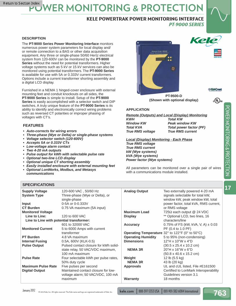
DESCRIPTION
The PT-9000 Series Power Monitoring Interface monitors numerous power system parameters for local display and/or remote connection to a BAS or other data acquisition equipment. Any three or single-phase 50/60 Hertz electrical system from 120-600V can be monitored by the PT-9000 Series without the need for potential transformers. Higher voltage systems such as 5 kV or 15 kV services can also be monitored using potential transformers. The PT-9000 Series is available for use with 5A or 0.333V current transformers. Options include a current transformer shorting assembly and a digital LCD display.
Furnished in a NEMA 1 hinged-cover enclosure with external mounting feet and conduit knockouts on all sides, the PT-9000 Series is simple to install. Setup of the PT-9000 Series is easily accomplished with a selector switch and DIP switches. A truly unique feature of the PT-9000 Series is its ability to identify and electronically correct wiring problems such as reversed CT polarities or improper phasing of voltages with CT's.
FEATURES• Auto-corrects for wiring errors• Three-phase (Wye or Delta) or single-phase systems• Voltage selector switch (120-600V)• Accepts 5A or 0.333V CTs• Low-voltage alarm contact• Two 4-20 mA outputs• Pulse output for kWh with selectable pulse rate• Optional two-line LCD display• Optional unique CT shorting assembly• Easily installed enclosure with external mounting feet• Optional LonWorks, Modbus, and Metasys
communications
SPECIFICATIONS
PT-9500-D (Shown with optional display)
APPLICATION
Remote (Outputs) and Local (Display) MonitoringKWH Total KWWindow KW Peak window KWTotal KVA Total power factor (PF)True RMS voltage True RMS current
Local (Display) Monitoring - Each PhaseTrue RMS voltageTrue RMS currentkW (Wye systems)kVA (Wye systems)Power factor (Wye systems)
All parameters can be monitored over a single pair of wires with a communications module installed.
January 2012
001-901-382-6084 International 888-397-5353 USA kele.com © 2012 Kele, Inc. All rights reserved. The Kele name and logo are registered trademarks of Kele, Inc.
POWER MONITORING & PROTECTION
764
POW
ER M
ON
ITO
RIN
G &
PRO
TECT
ION
17
KELE POWERTRAK POWER MONITORING INTERFACE PT-9000 SERIES
CONFIGURATION
DIP SwitchesSetting the DIP switches according to system requirements is suggested before applying power to the PT-9000 Series. However, it is not necessary to remove power from the PT-9000 Series in order to make changes to the DIP switch settings.A1 - A2: Defi ne the power system type. Set these switches to match the type of system that is to be monitored. Select from three-
phase Wye or Delta and single-phase two- or three-wire systems.A3 - A8: Defi ne the low-voltage alarm threshold. Select an appropriate value for the system voltage that is monitored. For Delta
systems, low voltage is measured line-to-line. For Wye and single-phase systems, low voltage is measured line-to-neutral. Select from alarm threshold values ranging from 51-540V.
B1 - B2: Defi ne the kWh per pulse value. Set these switches to obtain an optimum pulse rate that can be read by the BAS controller or data acquisition equipment. Select from 10, 1, 0.1, and 0.01 kWh per pulse values.
B3 - B5: Defi ne mA loop #2 signal type. Set these switches for the power parameter to be represented by this 4-20 mA output. Select from seven different parameters: Total kW, Window kW, Peak Window kW, Total kVA, Total Power Factor, True RMS Voltage*, True RMS Current*.
B6 - B8: Defi ne mA loop #1 signal type. Set these switches for the power parameter to be represented by this 4-20 mA output. Select from seven different parameters: Total kW, Window kW, Peak Window kW, Total kVA, Total Power Factor, True RMS Voltage*, True RMS Current*.
C1 - C5: Defi ne the current transformer ratio. Set switches to match the primary current rating of the current transformers connected to the PT-9000 Series. Select from CT primaries ranging from 50 to 6000.
* Voltage and current outputs are the average of the three-phase true RMS values.
System Voltage Select SwitchSet the SYSTEM VOLTAGE SELECT switch to the correct line-to-line system voltage (or potential transformer secondary voltage, if used) connected to the PT-9000 Series. If the actual system voltage is greater than the selector switch setting, the over voltage LED will fl ash, and the PT-9000 Series will cycle on and off to protect itself from over voltage. If this occurs, turn the selector switch to the correct system voltage setting.
Auto-Confi gurationAfter all wiring connections are completed, the DIP switches are set correctly, the voltage selector switch is set to the correct system voltage, and the electrical system is energized, the PT-9000 Series can be auto-confi gured. To initiate the autoconfi guring system, press the AUTO-CONFIG button. The PT-9000 Series will examine the current and voltage waveforms for correct phasing and CT polarity. During the auto-confi guring process, the Volts/Amps phasing LEDs and CT reverse polarity LEDs will light in sequence. When the process is completed only one of the Volts/Amps phasing LEDs will be lighted, indicating the actual phasing between the voltage and current inputs to the PT-9000 Series. A lighted CT polarity LED indicates that the corresponding CT is installed or wired backwards giving a reverse polarity. A correctly wired PT-9000 Series will be indicated by all CT polarity LEDs extinguished and the left-most Volts/Amps phasing LED lighted. Should any of the other phasing or CT polarity LEDs be lighted, the PT-9000 Series will electronically fi x the wiring errors and provide correct and accurate outputs. No time-consuming troubleshooting or wire swapping is required.
Manual Confi gurationIf the auto-confi guring system is unable to determine the correct wiring confi guration, the PT-9000 Series will enter the manual confi guration mode, and the manual confi g yellow LED will light. If this occurs, try initiating the auto-confi guring system again, otherwise proceed with manual confi guration. The electrical system load should be relatively constant during the manual confi guration procedure. To manually confi gure the PT-9000 Series, set the DIP switches so that one of the 4-20 mA outputs represents Total KW. Connect a meter set to read DC milliamps to this output, or if the PT-9000 Series has the LCD display option, set one of the display lines to read Total kW. Next, press the manual confi g CT polarity button (CT POL) to scan through the different CT polarity combinations. Each time, record the reading of the Total kW display or mA output. Allow the reading to stabilize before recording it. After reviewing all of the CT polarity combinations, press the manual confi g V-A MATCH button and repeat the process of scanning through the CT polarity combinations. After trying all possible combinations of V-A match and CT polarity, the correct confi guration is the one producing the highest value of kW on the display or the highest mA reading on the meter. Manually set the PT-9000 Series to the correct confi guration using the CT POL and V-A MATCH push buttons.
January 2012
© 2012 Kele, Inc. All rights reserved. The Kele name and logo are registered trademarks of Kele, Inc. kele.com 888-397-5353 USA 001-901-382-6084 International 765
POWER MONITORING & PROTECTIONPO
WER M
ON
ITORIN
G & PRO
TECTION
17
KELE POWERTRAK POWER MONITORING INTERFACE PT-9000 SERIES
X2 X1
X2 X1
X2 X1
H1
H1
H1
CT
CT
CTL1 (AØ)
L2 (BØ)
L3 (CØ)
Neutral (if Wye system)
L
I
N
E
L
O
A
D
CT H1 should faceline side
Neutral(if Wyesystem)
L3 L2 L1
CTCX2 X1
CTBX2 X1
CTAX2 X1
CTCX2 X1
CTBX2 X1
CTAX2 X1
12
34
56
78
12
34
56
78
12
34
5
PWR SYSTYPE
LOWVOLTS
THRESHOLDDIP
SW
ITC
H A
CT InputsTerminal Block System Voltage
Connections
NEUTRAL L3 L2 L1
Optional Potential TransformerFor Voltages Above 600V (see PT Wiring Option)
346-415V
440-480V
OFF
CLEARPEAKKW
CLEARKWH
COUNT
KWH/PULSE
mA OUT 2SIGNALSELECT
mA OUT 1SIGNALSELECT
CT RATIOSELECT
DIP
SW
ITC
H B
DIP
SW
ITC
H C
1 2 3
A B C
1 2 3
A B C
1 2 3
A B C
1 2 3
A B C
1 2 3
A B C
1 2 3
A B C
CTA
REVERSEPOLARITY
CTB
REVERSEPOLARITY
CTC
REVERSEPOLARITY
VOLTS
AMPS
AUTOCONFIG
MANUALCONFIG
V-A MATCH CT POL
SYS VOLTS OK KWH PULSE LOOP 2 UP LOOP 1 UP
SYS VOLTS OK KWH PULSE MA OUT 2 MA OUT 1
Low VoltageAlarm Output
(closes on alarm)
KWH PulseOutput
4-20 mAOutput #2
24 VDCPowerSupply
4-20 mAOutput #1
OVER VOLTSLED
X2 X1 X2 X1 X2 X1
A
NO
RM
SHORT
B
NO
RM
SHORT
C
NO
RM
SHORT
Optional CT Shorting Assembly Detail
System Voltage Select Switch
InputVoltageFusing
(2) KLK-0.5600V
120-144V190-277V
MAKE CT CONNECTIONSTO THESE TERMINALS
CTC CTB CTA
CT shorting jumpers shownin the normal position
CT shorting assembly pinssecured to PT-9000 CT InputsTerminal Block
PT-9000SERIES
Optional Cover-MountedLCD Display Detail*
*Manually scroll individual lines of display using thecover-mounted push buttons, to select differentpower system parameters.
Locationof
OptionalCommunications
Module
11
1
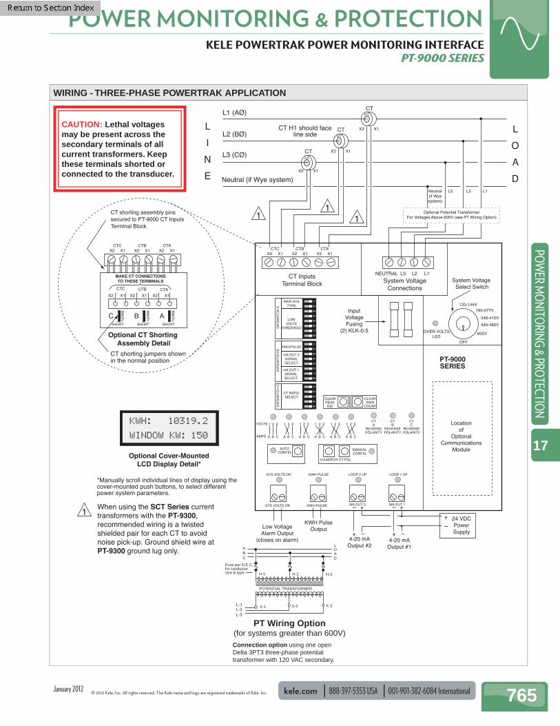
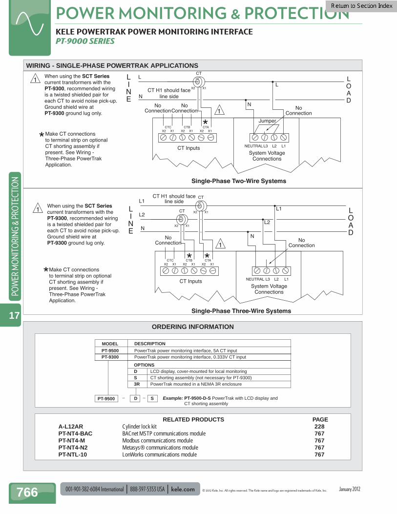
1When using the SCT Series currenttransformers with the PT-9300, recommended wiring is a twisted shielded pair for each CT to avoidnoise pick-up. Ground shield wire atPT-9300 ground lug only.
WIRING - THREE-PHASE POWERTRAK APPLICATION
Connection option using one openDelta 3PT3 three-phase potential transformer with 120 VAC secondary.
POTENTIAL TRANSFORMER
H-3H-2
X-3X-2
H-1
X-1
ABC
Fuse per N.E.C. for conductor size & type.
L-3L-2L-1
LOAD
PT Wiring Option(for systems greater than 600V)
CAUTION: Lethal voltages may be present across the secondary terminals of all current transformers. Keep these terminals shorted or connected to the transducer.
January 2012
001-901-382-6084 International 888-397-5353 USA kele.com © 2012 Kele, Inc. All rights reserved. The Kele name and logo are registered trademarks of Kele, Inc.
POWER MONITORING & PROTECTION
766
POW
ER M
ON
ITO
RIN
G &
PRO
TECT
ION
17
X2 X1
H1
CTL
N
L
N
LINE
LOAD
CT H1 should faceline side
CTCX2 X1
CTBX2 X1
CTAX2 X1
CT InputsSystem Voltage
Connections
NEUTRAL L3 L2 L1
NoConnection
NoConnection No
Connection
NoConnection
NoConnection
Jumper
X2 X1
H1
CTL1
N
L1
X2 X1
H1
CTL2
L2
N
LINE
LOAD
CT H1 should faceline side
CTCX2 X1
CTBX2 X1
CTAX2 X1
CT InputsSystem Voltage
Connections
NEUTRAL L3 L2 L1
Single-Phase Three-Wire Systems
Single-Phase Two-Wire Systems
**
* *
Make CT connectionsto terminal strip on optionalCT shorting assembly if present. See Wiring -Three-Phase PowerTrakApplication.
*Make CT connectionsto terminal strip on optionalCT shorting assembly if present. See Wiring - Three-Phase PowerTrakApplication.
1When using the SCT Seriescurrent transformers with the PT-9300, recommended wiring is a twisted shielded pair for each CT to avoid noise pick-up. Ground shield wire atPT-9300 ground lug only. 1
1
1When using the SCT Seriescurrent transformers with the PT-9300, recommended wiring is a twisted shielded pair for each CT to avoid noise pick-up. Ground shield wire atPT-9300 ground lug only.
KELE POWERTRAK POWER MONITORING INTERFACE PT-9000 SERIES
ORDERING INFORMATION
Example: PT-9500-D-S PowerTrak with LCD display and CT shorting assembly
PT-9500 D S
MODEL DESCRIPTION
PT-9500 PowerTrak power monitoring interface, 5A CT inputPT-9300 PowerTrak power monitoring interface, 0.333V CT input
OPTIONSD LCD display, cover-mounted for local monitoringS CT shorting assembly (not necessary for PT-9300) 3R PowerTrak mounted in a NEMA 3R enclosure
WIRING - SINGLE-PHASE POWERTRAK APPLICATIONS
January 2012
RELATED PRODUCTS PAGE A-L12AR Cylinder lock kit 228 PT-NT4-BAC BACnet MSTP communications module 767 PT-NT4-M Modbus communications module 767 PT-NT4-N2 Metasys® communications module 767 PT-NTL-10 LonWorks communications module 767
© 2012 Kele, Inc. All rights reserved. The Kele name and logo are registered trademarks of Kele, Inc. kele.com 888-397-5353 USA 001-901-382-6084 International 767
POWER MONITORING & PROTECTIONPO
WER M
ON
ITORIN
G & PRO
TECTION
17
ORDERING INFORMATION
COMMUNICATION MODULES FOR PT-9000 PT-NT4-BAC, PT-NTL-10, PT-NT4-N2, AND PT-NT4-M
Communication PT-NTL-10 LonWorks FTT-10 transceiver PT-NT4-N2 Metasys N2 protocol, RS-485,
halfduplex, 9600 baud PT-NT4-M Modbus protocol, RS-485, half
duplex, selectable baud rate PT-NT4-BAC BACnet MSTP protocol, RS485
halfduplex selectable baud rate Connections Pluggable screw terminals Operating Temperature 32° to 122°F (0° to 50°C) Operating Humidity 0% to 95% (non-condensing) Dimensions 4.5''H x 2.6''W x .6''D
(11.4 x 6.6 x 1.5 cm) Weight 0.7 lb (0.32 kg) Approvals UL listed, File #E161500 PT-NTL-10 Certifi ed to LonMark Interoperability
Guidelines v 3.1 PT-NT4-N2 Complies with Metasys guidelines Warranty 18 months
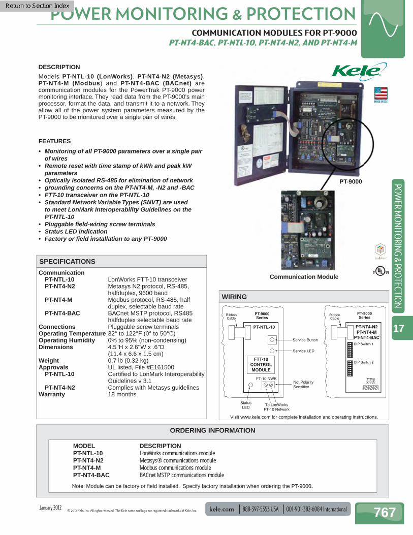
DESCRIPTION
Models PT-NTL-10 (LonWorks), PT-NT4-N2 (Metasys), PT-NT4-M (Modbus) and PT-NT4-BAC (BACnet) are communication modules for the PowerTrak PT-9000 power monitoring interface. They read data from the PT-9000's main processor, format the data, and transmit it to a network. They allow all of the power system parameters measured by the PT-9000 to be monitored over a single pair of wires.
FEATURES
• Monitoring of all PT-9000 parameters over a single pair of wires
• Remote reset with time stamp of kWh and peak kW parameters
• Optically isolated RS-485 for elimination of network• grounding concerns on the PT-NT4-M, -N2 and -BAC• FTT-10 transceiver on the PT-NTL-10• Standard Network Variable Types (SNVT) are used
to meet LonMark Interoperability Guidelines on the PT-NTL-10
• Pluggable fi eld-wiring screw terminals• Status LED indication• Factory or fi eld installation to any PT-9000
PT-9000Series
PT-NTL-10
RibbonCable
StatusLED
To LonWorksFT-10 Network
Service Button
Not PolaritySensitive
Service LED
FTT-10CONTROLMODULE
FT-10 NWK
WIRING
MODEL DESCRIPTION PT-NTL-10 LonWorks communications module PT-NT4-N2 Metasys® communications module PT-NT4-M Modbus communications module PT-NT4-BAC BACnet MSTP communications module
SPECIFICATIONS
PT-9000Series
PT-NT4-N2
PT-NT4-M
PT-NT4-N2PT-NT4-M
PT-NT4-BAC
12
34
56
78
12
34
56
78
DIP Switch 2
DIP Switch 1
GN
DB
(-)A
(+)
RibbonCable
PT-9000
Communication Module
Visit www.kele.com for complete installation and operating instructions.
Note: Module can be factory or fi eld installed. Specify factory installation when ordering the PT-9000.
January 2012

001-901-382-6084 International 888-397-5353 USA kele.com © 2012 Kele, Inc. All rights reserved. The Kele name and logo are registered trademarks of Kele, Inc.
POWER MONITORING & PROTECTION
768
POW
ER M
ON
ITO
RIN
G &
PRO
TECT
ION
17
ORDERING INFORMATION
VOLTAGE DISCONNECT SWITCH BLOCK, CT SHORTING SWITCHES U3889, 209PF
Voltage Rating 600V Current Rating 30 A Dimensions Switch 9.5"L x 3.5"W x 2.75"D (24.1 x 8.9 x 7 cm)Cover (209PF) 10.1"L x 4.6"W x 3.1"D (25.7 x 11.7 x 7.9 cm)Optional enclosure Metal screw cover box, NEMA 1 12"L x 10"W x 4"D (30.5 x 25.4 x 10.2 cm) Weight 2.9 lb (1.3 kg) 3.5 lb (1.5 kg) with cover 11 lb (5 kg) with enclosure Approvals UL-recognized component, File #E109317 Warranty Lifetime (normal use)
DESCRIPTION
The Model U3889 Voltage Disconnect Switch Blockprovides a means for disconnecting power monitoring equipment. It provides isolation from line voltage and will short out and disconnect current transformer secondaries, preventing transformer damage that may occur when the circuit is opened under load. One side of the switch is connected to the circuits being measured; the other side of the switch is connected to the power monitoring equipment. The black plastic cover (209PF) is constructed so that all switches must be in the closed position before the cover can be sealed.
FEATURES
• Provides voltage disconnect and CT shorting/ disconnect for power instrumentation
• Available in convenient metal screw cover enclosure• Color-coded switch handles• UL recognized
To Power MonitoringEquipment
To PhaseVoltage
To CTSecondary
Notes: 1. Red switch pulled up disconnects voltage.2. Black switch pair pulled up shorts CT secondary and disconnects load from CT.
WIRING
SPECIFICATIONS
209PF
MODEL DESCRIPTION U3889-E Switch block mounted in a 12" x 10" x 4" metal screw cover box U3889 Switch block 209PF Switch cover (not for use with U3889-E)
U3889
U3889-E
January 2012
© 2012 Kele, Inc. All rights reserved. The Kele name and logo are registered trademarks of Kele, Inc. kele.com 888-397-5353 USA 001-901-382-6084 International 769
POWER MONITORING & PROTECTIONPO
WER M
ON
ITORIN
G & PRO
TECTION
17
GP SERIES POWER METER GP SERIES
Supply Voltage UL 90 VAC (L-N) to 600 VAC (L-L),
50/60Hz CE 90 VAC (L-N) to 300 VAC (L-L),
50/60Hz Monitored Voltage Line to Line: 90 to 600 VAC Line to Line with potential transformer: 601 to 32000 VAC Monitored Current 5 to 32,000 Amps Input 0 to 0.333 V or 0 to 1 V Input Signal 2 (GP953 only) Pulse Solid-State
or mechanical contacts (current less than 1 mA) Minimum Pulse Width 20 msec
Outputs GP911 Reactive energy pulse 30 VAC/DC GP921 RS-485 2-wire Modbus RTU Basic
Data Set
GP9122/GP922 RS-485 2-wire Modbus RTU Full Data Set
GP122/GP923 RS-485 2-wire Modbus RTU Full Data Set, data logging
GP953 RS-485 2-wire BACnet MS/TP Full Data Set, data logging
Accuracy Real power and energy 0.5% (ANSI C12.20, IEC 62053-22 Class 0.5S)
Operating Temperature Meter -22° to 158°F (-30° to 70°C) Display 14° to 122°F (-10° to 50°C)
Operating Humidity < 95% RH non-condensing Mounting DIN Rail or 3-point screw mount Dimensions 2.3" x 4.2" x 3.6"
(5.9 cm x 10.7 cm 9.1 cm) Weight 0.62 lb (0.28 kg) Approvals CE, UL508, File #E339785, RoHS Statement Yes Warranty 5 years
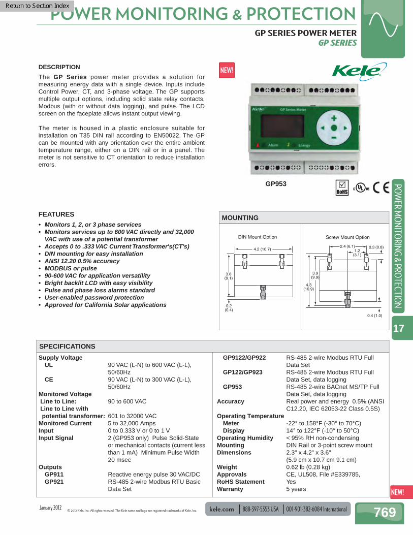
3.6(9.1)
4.2 (10.7)
0.2(0.4)
3.9(9.9)
2.4 (6.1)
++
+
4.3(10.9)
1.2(3.1)
0.3 (0.8)
0.4 (1.0)
DIN Mount Option Screw Mount Option
DESCRIPTION
The GP Series power meter provides a solution for measuring energy data with a single device. Inputs include Control Power, CT, and 3-phase voltage. The GP supports multiple output options, including solid state relay contacts, Modbus (with or without data logging), and pulse. The LCD screen on the faceplate allows instant output viewing.
The meter is housed in a plastic enclosure suitable for installation on T35 DIN rail according to EN50022. The GP can be mounted with any orientation over the entire ambient temperature range, either on a DIN rail or in a panel. The meter is not sensitive to CT orientation to reduce installation errors.
FEATURES• Monitors 1, 2, or 3 phase services • Monitors services up to 600 VAC directly and 32,000
VAC with use of a potential transformer• Accepts 0 to .333 VAC Current Transformer's(CT's)• DIN mounting for easy installation• ANSI 12.20 0.5% accuracy• MODBUS or pulse • 90-600 VAC for application versatility• Bright backlit LCD with easy visibility• Pulse and phase loss alarms standard• User-enabled password protection• Approved for California Solar applications
MOUNTING
SPECIFICATIONS
January 2012
GP953

001-901-382-6084 International 888-397-5353 USA kele.com © 2012 Kele, Inc. All rights reserved. The Kele name and logo are registered trademarks of Kele, Inc.
POWER MONITORING & PROTECTION
770
POW
ER M
ON
ITO
RIN
G &
PRO
TECT
ION
17
GP SERIES POWER METER GP SERIES
1-Phase Line-to-Neutral 2 - Wire System 1 CT
Customer Supplied (1/2 Amp Fuse)
WIRING
BACNET/MODBUS DATA OUTPUTS
ORDERING INFORMATION MODEL DESCRIPTION GP122 Power meter bi-directional, Modbus, Pulse output GP123 Power meter, bi-directional, Modbus, pulse output , data logging GP911 Pulse output only GP921 Modbus output, basic data set GP922 Modbus output, full data set GP923 Modbus output, full data set, data logging GP953 Power meter FDS BACnet, 2 pulse inputs,data logging GP-AE003 Nema 4 enclosure for GP Series meters GP-AH02 Fuse pack, single GP-AH03 Fuse pack, double GP-AH04 Fuse pack, triple
1-Phase Line-to-Line-Wire System 1 CT
Customer Supplied (1/2 Amp Fuse)
1-Phase Direct Voltage Connection 2 CT
Customer Supplied (1/2 Amp Fuse)
3-Phase 3-Wire 3 CT no PT
Customer Supplied (1/2 Amp Fuse)
3-Phase 4-Wire Wye Direct Voltage Input Connection 3 CT
Customer Supplied (1/2 Amp Fuse)
3-Phase 4-Wire Wye Connection 3 CT 3 PTCustomer Supplied (1/2 Amp Fuse)
January 2012
Basic Data Set (BDS): Power (kW) Energy (kWh)
Full Data Set (FDS) includes BDS plus: Confi gurable for CT & PT ratios, system type, and passwords Diagnostic alerts Current: 3-phase average Volts: 3-phase average Current: by phase Volts: by phase Line-Line and Line-Neutral Power: Real, Reactive, and Apparent 3-phase total and per phase Power Factor: 3-phase average and per phase Frequency Power Demand: Most Recent and Peak Demand Confi guration: Fixed, Rolling Block, and External Sync (Modbus only)
Data Logging (includes all FDS outputs, plus): Real Time Clock: user confi gurable 10 user confi gurable log buffers: each buffer holds 5760 16-bit entries (User confi gures which 10 data points are stored in these buffers)
User confi gurable logging interval(When confi gured for a 15 minute interval, each buffer holds 60 days of data) Continuous and Single Shot logging modes: user selectable Auto write pause: read logs without disabling the meter's data logging mode
BACnet Data Logging (includes all FDS outputs, plus): Real Time Clock: uses BACnet Time Synchronization services 3 BACnet log events: each buffer holds 5760 32-bit entries (User confi gures which 3 data points are stored in these buffers) User confi gurable logging interval, (When confi gured for a 15 minute interval,each buffer holds 60 days of data) Continuous and single shot logging modes: user selectable Auto write pause: read logs without disabling the meter's data logging mode
© 2012 Kele, Inc. All rights reserved. The Kele name and logo are registered trademarks of Kele, Inc. kele.com 888-397-5353 USA 001-901-382-6084 International 771
POWER MONITORING & PROTECTIONPO
WER M
ON
ITORIN
G & PRO
TECTION
17
ADVANCED KWH/DEMAND METER CLASS 500 SUBMETERS
Supply Voltage Up to 600 VAC RMS available, 50/60Hz
Battery Description Non-rechargeable cell used for
memory retention Manufacturer Eagle-picher Mfg Part No. LTC-3PN Working Voltage 3.5 Vdc Current Capacity 350 mAHr Electrolyte Lithium thionyl nitrate Communication Modbus RTU or TCP/IP BACnet IP or MS/TP LonWorks Input 3-wire (Delta) or 4-wire (WYE) Current Rating Sensors - Up to 3200 Amp RMS AC
available Overload Rating Voltage Overload +25% continuously; +100% for 20
cycles Current Sensor Overload
100% for 1 minute without damaging meter
Accuracy Certifi ed to ANSI C12.16
Range 4 Wire Wye 115/208 VAC: 100, 200, 400, 800,
1600, 3200 Amp4 Wire Wye 277/480 VAC: 100, 200, 400, 800,
1600, 3200 Amp3 Wire Delta 220/240 VAC: 100, 200, 400, 800,
1600, 3200 Amp3 Wire Delta 480 VAC: 100, 200, 400, 800, 1600,
3200 Amp Operating Temperature
NEMA 4 (Outdoor) Housing: -4° to 158°F (-20° to 70°C)
NEMA 12 (Indoor) Housing: -4° to 122°F (-20° to 50°C)
Operating Humidity 0 to 95% RH (non-condensing) Housing Type
Models with R NEMA 4Models without R NEMA 12
Dimensions 7.5 " H x 7 " W x 3.75 " D (19.1 x 17.8 x 8.3 cm)
Approvals UL fi le#E249361 Warranty 1 year
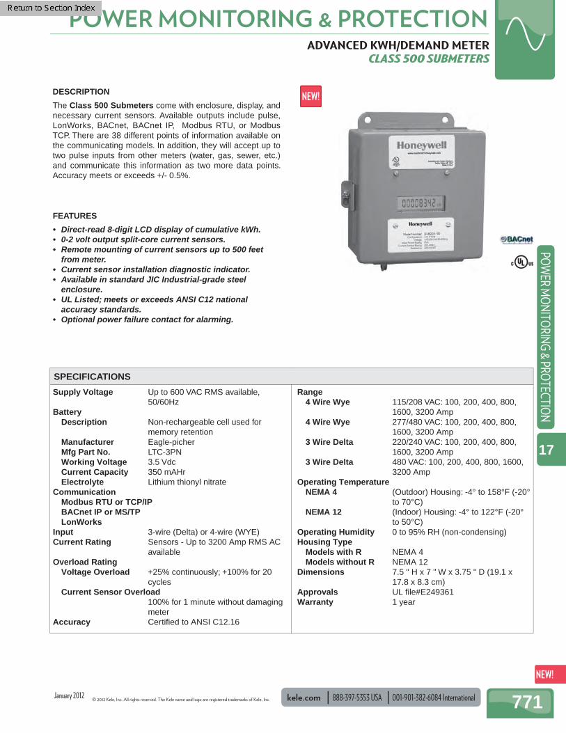
DESCRIPTION
The Class 500 Submeters come with enclosure, display, and necessary current sensors. Available outputs include pulse, LonWorks, BACnet, BACnet IP, Modbus RTU, or Modbus TCP. There are 38 different points of information available on the communicating models. In addition, they will accept up to two pulse inputs from other meters (water, gas, sewer, etc.) and communicate this information as two more data points. Accuracy meets or exceeds +/- 0.5%.
FEATURES
• Direct-read 8-digit LCD display of cumulative kWh. • 0-2 volt output split-core current sensors. • Remote mounting of current sensors up to 500 feet
from meter. • Current sensor installation diagnostic indicator. • Available in standard JIC Industrial-grade steel
enclosure. • UL Listed; meets or exceeds ANSI C12 national
accuracy standards. • Optional power failure contact for alarming.
SPECIFICATIONS
January 2012
001-901-382-6084 International 888-397-5353 USA kele.com © 2012 Kele, Inc. All rights reserved. The Kele name and logo are registered trademarks of Kele, Inc.
POWER MONITORING & PROTECTION
772
POW
ER M
ON
ITO
RIN
G &
PRO
TECT
ION
17
ORDERING INFORMATION
ADVANCED KWH/DEMAND METER CLASS 500 SUBMETERS
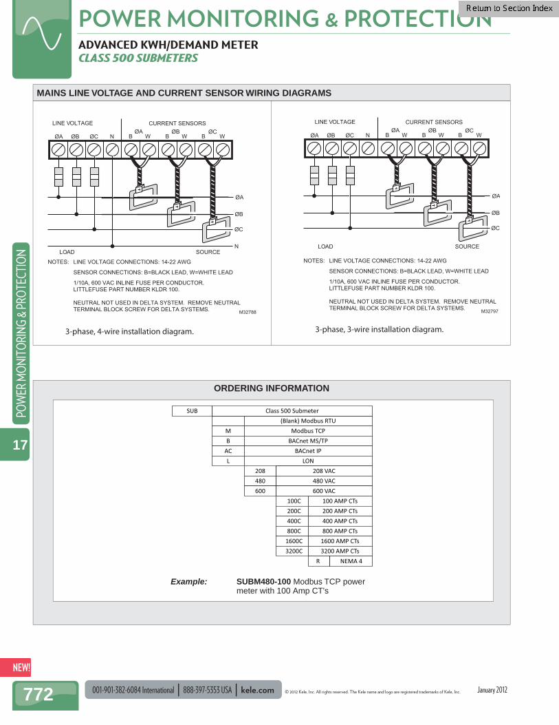
MAINS LINE VOLTAGE AND CURRENT SENSOR WIRING DIAGRAMS
SUB
MB
ACL
208480600
100C200C400C800C
1600C3200C
(Blank) Modbus RTUModbus TCP
BACnet MS/TPBACnet IP
LON208 VAC 480 VAC600 VAC
100 AMP CTs200 AMP CTs400 AMP CTs800 AMP CTs
1600 AMP CTs3200 AMP CTs
Class 500 Submeter
NEMA 4R
3-phase, 4-wire installation diagram. 3-phase, 3-wire installation diagram.
B W N
LINE VOLTAGE
ØA
ØC
ECRUOSDAOL
ØBB W
M32788
ØAØA ØB ØC
ØB
B W
CURRENT SENSORS
ØC
N
NOTES: LINE VOLTAGE CONNECTIONS: 14-22 AWG
SENSOR CONNECTIONS: B=BLACK LEAD, W=WHITE LEAD
1/10A, 600 VAC INLINE FUSE PER CONDUCTOR. LITTLEFUSE PART NUMBER KLDR 100.
NEUTRAL NOT USED IN DELTA SYSTEM. REMOVE NEUTRAL TERMINAL BLOCK SCREW FOR DELTA SYSTEMS.
B W N
LINE VOLTAGE
ØA
ØC
ECRUOSDAOL
ØBB W
M32797
ØAØA ØB ØC
ØB
B W
CURRENT SENSORS
ØC
NOTES: LINE VOLTAGE CONNECTIONS: 14-22 AWG SENSOR CONNECTIONS: B=BLACK LEAD, W=WHITE LEAD 1/10A, 600 VAC INLINE FUSE PER CONDUCTOR. LITTLEFUSE PART NUMBER KLDR 100.
NEUTRAL NOT USED IN DELTA SYSTEM. REMOVE NEUTRAL TERMINAL BLOCK SCREW FOR DELTA SYSTEMS.
January 2012
Example: SUBM480-100 Modbus TCP power meter with 100 Amp CT's
© 2012 Kele, Inc. All rights reserved. The Kele name and logo are registered trademarks of Kele, Inc. kele.com 888-397-5353 USA 001-901-382-6084 International 773
POWER MONITORING & PROTECTIONPO
WER M
ON
ITORIN
G & PRO
TECTION
17
Secondary 0-5A Frequency 50-400 Hz Insulation Class 600V, 10 kV BIL Lead Wires 24" (61 cm), 16 AWG Materials Of Construction
Plastic, UL94V-1 Weight 2AL 0.5 lb (0.23 kg) 5RL 1.0 lb (0.45 kg) 7RL 1.5 lb (0.63 kg) 8RL 2.5 lb (1.2 kg) Approvals UL-recognized component, File
#E93779; CSA certifi ed, File #LR89403
Warranty 1 year
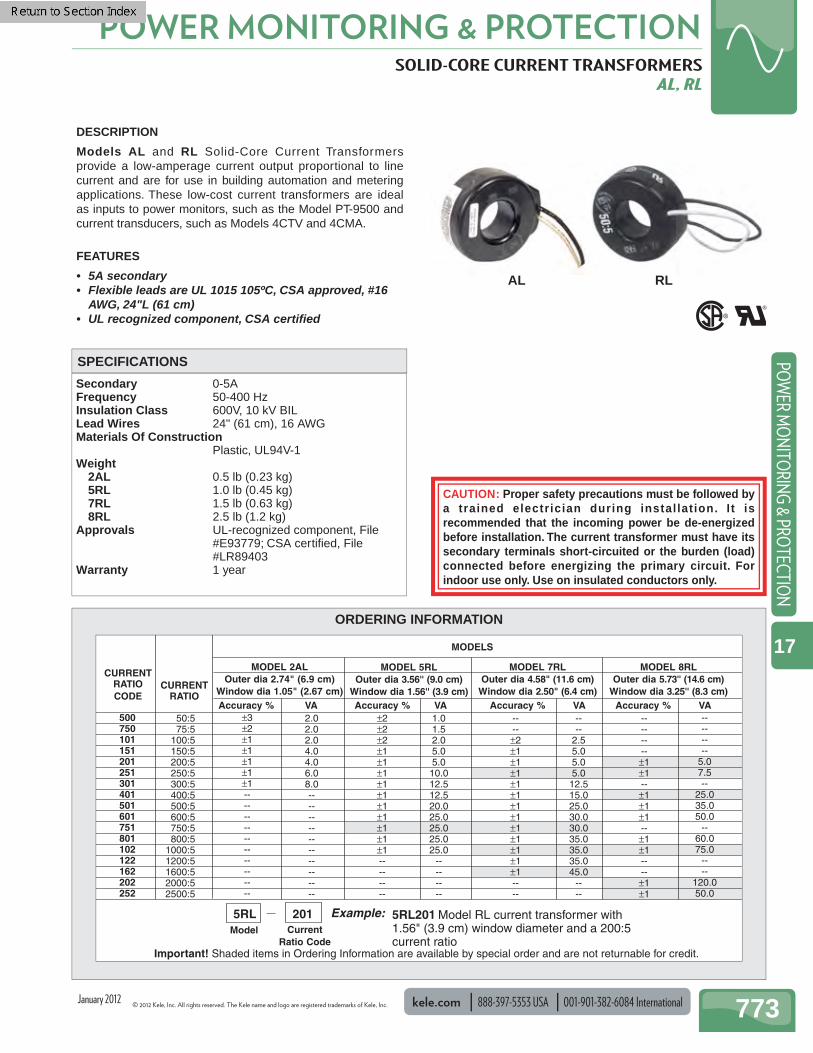
SOLID-CORE CURRENT TRANSFORMERS AL, RL
DESCRIPTION
Models AL and RL Solid-Core Current Transformers provide a low-amperage current output proportional to line current and are for use in building automation and metering applications. These low-cost current transformers are ideal as inputs to power monitors, such as the Model PT-9500 and current transducers, such as Models 4CTV and 4CMA.
FEATURES
• 5A secondary• Flexible leads are UL 1015 105ºC, CSA approved, #16
AWG, 24"L (61 cm) • UL recognized component, CSA certifi ed
SPECIFICATIONS
AL
ORDERING INFORMATION
CURRENTRATIO
MODELS
CURRENTRATIOCODE
MODEL 2ALOuter dia 2.74" (6.9 cm)
Window dia 1.05" (2.67 cm)
MODEL 5RLOuter dia 3.56'' (9.0 cm)
Window dia 1.56'' (3.9 cm)
MODEL 7RLOuter dia 4.58" (11.6 cm)
Window dia 2.50" (6.4 cm)
MODEL 8RLOuter dia 5.73'' (14.6 cm)
Window dia 3.25'' (8.3 cm)Accuracy %
50:575:5
100:5 150:5 200:5 250:5 300:5 400:5 500:5 600:5 750:5 800:5
1000:5 1200:5 1600:5 2000:5 2500:5
500750101151201251301401501601751801102122162202252
±3±2±1±1±1±1±1--------------------
2.02.02.04.04.06.08.0--------------------
1.01.52.05.05.010.012.512.520.025.025.025.025.0
--------
----±2±1±1±1±1±1±1±1±1±1±1±1±1----
Example:Model Current
Ratio CodeImportant! Shaded items in Ordering Information are available by special order and are not returnable for credit.
5RL 201 5RL201 Model RL current transformer with 1.56" (3.9 cm) window diameter and a 200:5current ratio
VA Accuracy % VA Accuracy % VA Accuracy % VA±2±2±2±1±1±1±1±1±1±1±1±1±1--------
--------±1±1--±1±1±1--±1±1----±1±1
--------
5.07.5--
25.035.050.0
--60.075.0
----
120.050.0
----
2.55.05.05.012.515.025.030.030.035.035.035.045.0
----
CAUTION: Proper safety precautions must be followed by a trained electrician during instal lat ion. I t is recommended that the incoming power be de-energized before installation. The current transformer must have its secondary terminals short-circuited or the burden (load) connected before energizing the primary circuit. For indoor use only. Use on insulated conductors only.
RL
January 2012
001-901-382-6084 International 888-397-5353 USA kele.com © 2012 Kele, Inc. All rights reserved. The Kele name and logo are registered trademarks of Kele, Inc.
POWER MONITORING & PROTECTION
774
POW
ER M
ON
ITO
RIN
G &
PRO
TECT
ION
17
Secondary 0-5A Frequency 50-400 Hz Continuous Current 1.33 @ 30°C ambient (86°F) 1.0 @
55°C ambient (131°F) Terminations Brass stud terminal with nut, fl at
washer, lockwasher Materials Of Construction
Plastic, UL94V-1 Insulation Class 600V, 10 kV BIL
Window Size 500T 4.1" x 7.1" (10.4 x 18.0 cm) 501T 4.1" x 11.7" (10.4 x 29.7 cm)
Weight 8 lb (3.6 kg) Approvals UL-recognized component, File
#E93779; CSA certifi ed, File #LR89403
Warranty 1 year
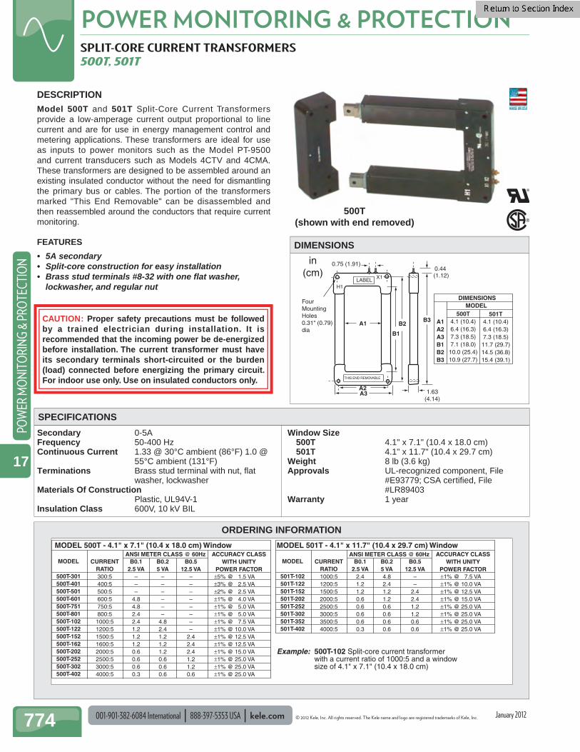
SPLIT-CORE CURRENT TRANSFORMERS 500T, 501T
0.75 (1.91)
Four Mounting Holes 0.31" (0.79) dia
LABEL
0.44 (1.12)
B3
1.63(4.14)
B2
B1
A3A2
THIS END REMOVABLE
A1
H1
X1
500T4.1 (10.4)6.4 (16.3)7.3 (18.5)7.1 (18.0)
10.0 (25.4)10.9 (27.7)
501T4.1 (10.4)6.4 (16.3)7.3 (18.5)
11.7 (29.7)14.5 (36.8)15.4 (39.1)
A1A2A3B1B2B3
DIMENSIONSMODEL
in(cm)
DESCRIPTIONModel 500T and 501T Split-Core Current Transformersprovide a low-amperage current output proportional to line current and are for use in energy management control and metering applications. These transformers are ideal for use as inputs to power monitors such as the Model PT-9500 and current transducers such as Models 4CTV and 4CMA.These transformers are designed to be assembled around an existing insulated conductor without the need for dismantling the primary bus or cables. The portion of the transformers marked "This End Removable" can be disassembled and then reassembled around the conductors that require current monitoring.
FEATURES
• 5A secondary• Split-core construction for easy installation• Brass stud terminals #8-32 with one fl at washer,
lockwasher, and regular nut
DIMENSIONS
SPECIFICATIONS
ORDERING INFORMATION
ACCURACY CLASSWITH UNITY
POWER FACTOR
MODEL 500T - 4.1" x 7.1" (10.4 x 18.0 cm) Window
CURRENTRATIO300:5400:5500:5600:5750:5800:51000:51200:51500:51600:52000:52500:53000:54000:5
B0.12.5 VA
–––
4.84.82.42.41.21.21.20.60.60.60.3
B0.25 VA
––––––
4.82.41.21.21.20.60.60.6
B0.512.5 VA
––––––––
2.42.42.41.21.20.6
ANSI METER CLASS @ 60Hz ACCURACY CLASSWITH UNITY
POWER FACTOR
MODEL 501T - 4.1" x 11.7" (10.4 x 29.7 cm) Window
MODEL
501T-102501T-122501T-152501T-202501T-252501T-302501T-352501T-402
CURRENTRATIO1000:51200:51500:52000:52500:53000:53500:54000:5
B0.12.5 VA
2.41.21.20.60.60.60.60.3
B0.25 VA4.82.41.21.20.60.60.60.6
B0.512.5 VA
––
2.42.41.21.20.60.6
ANSI METER CLASS @ 60Hz
Example: 500T-102 Split-core current transformer with a current ratio of 1000:5 and a window size of 4.1" x 7.1" (10.4 x 18.0 cm)
MODEL
500T-301500T-401500T-501500T-601500T-751500T-801500T-102500T-122500T-152500T-162500T-202500T-252500T-302500T-402
±1% @ 7.5 VA±1% @ 10.0 VA±1% @ 12.5 VA±1% @ 15.0 VA±1% @ 25.0 VA±1% @ 25.0 VA±1% @ 25.0 VA±1% @ 25.0 VA
±5% @ 1.5 VA ±3% @ 2.5 VA ±2% @ 2.5 VA ±1% @ 4.0 VA±1% @ 5.0 VA±1% @ 5.0 VA±1% @ 7.5 VA±1% @ 10.0 VA±1% @ 12.5 VA±1% @ 12.5 VA ±1% @ 15.0 VA±1% @ 25.0 VA±1% @ 25.0 VA±1% @ 25.0 VA
500T(shown with end removed)
CAUTION: Proper safety precautions must be followed by a trained electrician during installation. It is recommended that the incoming power be de-energized before installation. The current transformer must have its secondary terminals short-circuited or the burden (load) connected before energizing the primary circuit. For indoor use only. Use on insulated conductors only.
January 2012
© 2012 Kele, Inc. All rights reserved. The Kele name and logo are registered trademarks of Kele, Inc. kele.com 888-397-5353 USA 001-901-382-6084 International 775
POWER MONITORING & PROTECTIONPO
WER M
ON
ITORIN
G & PRO
TECTION
17
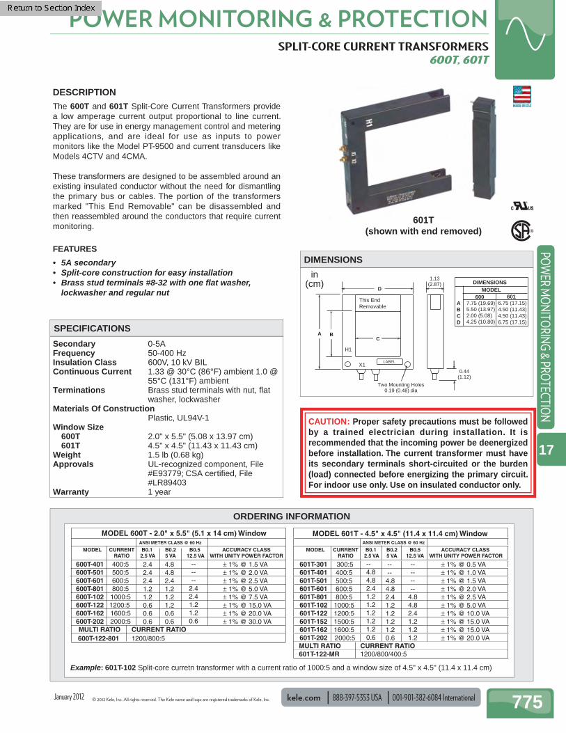
SPLIT-CORE CURRENT TRANSFORMERS 600T, 601T
Secondary 0-5A Frequency 50-400 Hz Insulation Class 600V, 10 kV BIL Continuous Current 1.33 @ 30°C (86°F) ambient 1.0 @
55°C (131°F) ambient Terminations Brass stud terminals with nut, fl at
washer, lockwasher Materials Of Construction
Plastic, UL94V-1 Window Size 600T 2.0" x 5.5" (5.08 x 13.97 cm) 601T 4.5" x 4.5" (11.43 x 11.43 cm) Weight 1.5 lb (0.68 kg) Approvals UL-recognized component, File
#E93779; CSA certifi ed, File #LR89403
Warranty 1 year
A
D
1.13(2.87)
CB
0.44(1.12)
Two Mounting Holes0.19 (0.48) dia
LABEL
6016.75 (17.15)4.50 (11.43) 4.50 (11.43) 6.75 (17.15)
DIMENSIONS MODEL
ABCD
X1
H1
This End Removable
6007.75 (19.69) 5.50 (13.97) 2.00 (5.08) 4.25 (10.80)
in(cm)
DESCRIPTION The 600T and 601T Split-Core Current Transformers provide a low amperage current output proportional to line current. They are for use in energy management control and metering applications, and are ideal for use as inputs to power monitors like the Model PT-9500 and current transducers like Models 4CTV and 4CMA.
These transformers are designed to be assembled around an existing insulated conductor without the need for dismantling the primary bus or cables. The portion of the transformers marked "This End Removable" can be disassembled and then reassembled around the conductors that require current monitoring.
FEATURES
• 5A secondary• Split-core construction for easy installation• Brass stud terminals #8-32 with one fl at washer,
lockwasher and regular nut
DIMENSIONS
SPECIFICATIONS
601T(shown with end removed)
ORDERING INFORMATION
CURRENT RATIO1200/800:5
MODEL 600T - 2.0" x 5.5" (5.1 x 14 cm) Window
MODEL CURRENTRATIO
B0.1 2.5 VA
B0.25 VA
B0.5 12.5 VA
ANSI METER CLASS @ 60 Hz ANSI METER CLASS @ 60 Hz
MULTI RATIO600T-122-801
ACCURACY CLASSWITH UNITY POWER FACTOR
4.8 4.8 2.4 1.2 1.2 1.2 0.6 0.6
2.42.4 2.4 1.2 1.2 0.6 0.6 0.6
400:5 500:5 600:5 800:5 1000:5 1200:5 1600:5 2000:5
600T-401 600T-501 600T-601 600T-801 600T-102 600T-122 600T-162 600T-202
± 1% @ 1.5 VA± 1% @ 2.0 VA± 1% @ 2.5 VA± 1% @ 5.0 VA± 1% @ 7.5 VA
± 1% @ 15.0 VA ± 1% @ 20.0 VA ± 1% @ 30.0 VA
------
2.42.41.21.20.6
MODEL CURRENTRATIO
B0.1 2.5 VA
B0.25 VA
B0.512.5 VA
-- --4.8 4.8 2.4 1.2 1.2 1.21.2 0.6
--------
4.84.82.41.21.21.2
601T-301601T-401 601T-501 601T-601 601T-801 601T-102 601T-122 601T-152 601T-162 601T-202
MODEL 601T - 4.5" x 4.5" (11.4 x 11.4 cm) Window
ACCURACY CLASS WITH UNITY POWER FACTOR
± 1% @ 0.5 VA± 1% @ 1.0 VA± 1% @ 1.5 VA± 1% @ 2.0 VA± 1% @ 2.5 VA± 1% @ 5.0 VA
± 1% @ 10.0 VA ± 1% @ 15.0 VA ± 1% @ 15.0 VA ± 1% @ 20.0 VA
300:5400:5 500:5 600:5 800:5 1000:5 1200:5 1500:5 1600:5 2000:5
--4.84.82.4 1.2 1.2 1.2 1.2 1.2 0.6
CURRENT RATIO1200/800/400:5
MULTI RATIO601T-122-MR
CAUTION: Proper safety precautions must be followed by a trained electrician during installation. It is recommended that the incoming power be deenergized before installation. The current transformer must have its secondary terminals short-circuited or the burden (load) connected before energizing the primary circuit. For indoor use only. Use on insulated conductor only.
Example: 601T-102 Split-core curretn transformer with a current ratio of 1000:5 and a window size of 4.5" x 4.5" (11.4 x 11.4 cm)
January 2012
001-901-382-6084 International 888-397-5353 USA kele.com © 2012 Kele, Inc. All rights reserved. The Kele name and logo are registered trademarks of Kele, Inc.
POWER MONITORING & PROTECTION
776
POW
ER M
ON
ITO
RIN
G &
PRO
TECT
ION
17
ORDERING INFORMATION
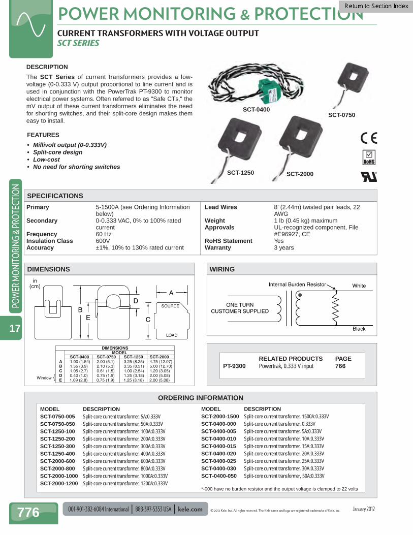
CURRENT TRANSFORMERS WITH VOLTAGE OUTPUT SCT SERIES
Primary 5-1500A (see Ordering Information below)
Secondary 0-0.333 VAC, 0% to 100% rated current
Frequency 60 Hz Insulation Class 600V Accuracy ±1%, 10% to 130% rated current
Lead Wires 8' (2.44m) twisted pair leads, 22 AWG
Weight 1 lb (0.45 kg) maximum Approvals UL-recognized component, File
#E96927, CE RoHS Statement Yes Warranty 3 years
SCT-0400 SCT-0750 SCT-1250 SCT-2000 A 1.00 (1.54) 2.00 (5.1) 3.25 (8.25) 4.75 (12.07) B 1.55 (3.9) 2.10 (5.3) 3.35 (8.51) 5.00 (12.70) C 1.05 (2.7) 0.61 (1.5) 1.00 (2.54) 1.20 (3.05) D 0.40 (1.0) 0.75 (1.9) 1.25 (3.18) 2.00 (5.08) E 1.09 (2.8) 0.75 (1.9) 1.25 (3.18) 2.00 (5.08)
MODELDIMENSIONS
in(cm)
{Window
A
C
SOURCE
LOAD
BE
D
DESCRIPTION
The SCT Series of current transformers provides a low-voltage (0-0.333 V) output proportional to line current and is used in conjunction with the PowerTrak PT-9300 to monitor electrical power systems. Often referred to as "Safe CTs," the mV output of these current transformers eliminates the need for shorting switches, and their split-core design makes them easy to install.
FEATURES
• Millivolt output (0-0.333V)• Split-core design• Low-cost• No need for shorting switches
White
ONE TURNCUSTOMER SUPPLIED
Black
Internal Burden Resistor
WIRINGDIMENSIONS
SPECIFICATIONS
MODEL DESCRIPTION SCT-0750-005 Split-core current transformer, 5A:0.333V SCT-0750-050 Split-core current transformer, 50A:0.333V SCT-1250-100 Split-core current transformer, 100A:0.333V SCT-1250-200 Split-core current transformer, 200A:0.333V SCT-1250-300 Split-core current transformer, 300A:0.333V SCT-1250-400 Split-core current transformer, 400A:0.333V SCT-2000-600 Split-core current transformer, 600A:0.333V SCT-2000-800 Split-core current transformer, 800A:0.333V SCT-2000-1000 Split-core current transformer, 1000A:0.333V SCT-2000-1200 Split-core current transformer, 1200A:0.333V
MODEL DESCRIPTION SCT-2000-1500 Split-core current transformer, 1500A:0.333V SCT-0400-000 Split-core current transformer, 0.333V SCT-0400-005 Split-core current transformer, 5A:0.333V SCT-0400-010 Split-core current transformer, 10A:0.333V SCT-0400-015 Split-core current transformer, 15A:0.333V SCT-0400-020 Split-core current transformer, 20A:0.333V SCT-0400-025 Split-core current transformer, 25A:0.333V SCT-0400-030 Split-core current transformer, 30A:0.333V SCT-0400-050 Split-core current transformer, 50A:0.333V
SCT-0400 SCT-0750
SCT-2000SCT-1250
January 2012
*-000 have no burden resistor and the output voltage is clamped to 22 volts
RELATED PRODUCTS PAGE PT-9300 Powertrak, 0.333 V input 766
© 2012 Kele, Inc. All rights reserved. The Kele name and logo are registered trademarks of Kele, Inc. kele.com 888-397-5353 USA 001-901-382-6084 International 777
POWER MONITORING & PROTECTIONPO
WER M
ON
ITORIN
G & PRO
TECTION
17
ORDERING INFORMATION
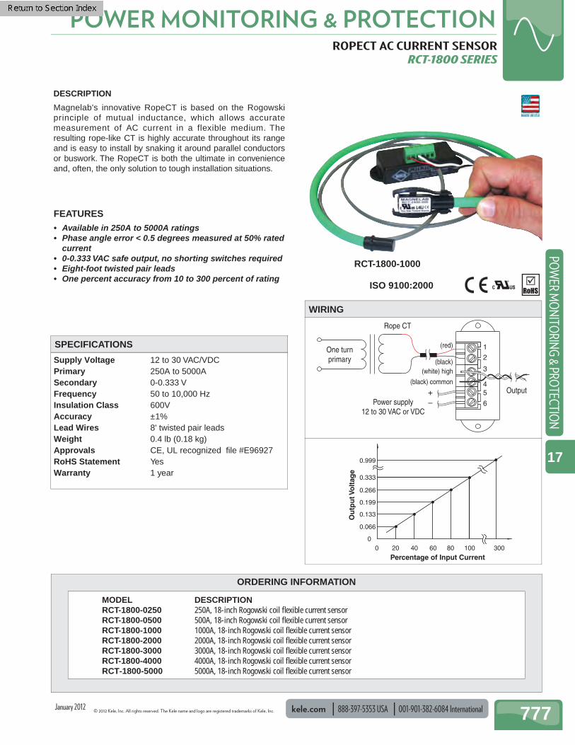
ROPECT AC CURRENT SENSOR RCT-1800 SERIES
Supply Voltage 12 to 30 VAC/VDC Primary 250A to 5000A Secondary 0-0.333 V Frequency 50 to 10,000 Hz Insulation Class 600V Accuracy ±1% Lead Wires 8' twisted pair leads Weight 0.4 lb (0.18 kg) Approvals CE, UL recognized fi le #E96927 RoHS Statement Yes Warranty 1 year
DESCRIPTION
Magnelab's innovative RopeCT is based on the Rogowski principle of mutual inductance, which allows accurate measurement of AC current in a flexible medium. The resulting rope-like CT is highly accurate throughout its range and is easy to install by snaking it around parallel conductors or buswork. The RopeCT is both the ultimate in convenience and, often, the only solution to tough installation situations.
FEATURES• Available in 250A to 5000A ratings• Phase angle error < 0.5 degrees measured at 50% rated
current• 0-0.333 VAC safe output, no shorting switches required• Eight-foot twisted pair leads• One percent accuracy from 10 to 300 percent of rating
1(red)
(black)(white) high
Rope CT
Output
One turnprimary
Power supply12 to 30 VAC or VDC
+–
(black) common
2
3
6
54
WIRING
SPECIFICATIONS
RCT-1800-1000
MODEL DESCRIPTION RCT-1800-0250 250A, 18-inch Rogowski coil fl exible current sensor RCT-1800-0500 500A, 18-inch Rogowski coil fl exible current sensor RCT-1800-1000 1000A, 18-inch Rogowski coil fl exible current sensor RCT-1800-2000 2000A, 18-inch Rogowski coil fl exible current sensor RCT-1800-3000 3000A, 18-inch Rogowski coil fl exible current sensor RCT-1800-4000 4000A, 18-inch Rogowski coil fl exible current sensor RCT-1800-5000 5000A, 18-inch Rogowski coil fl exible current sensor
0.999
0.333
0.266
0.199
0.133
0.066
00 20 40
Percentage of Input Current
Ou
tpu
t Vo
ltag
e
60 80 100 300
ISO 9100:2000
January 2012

001-901-382-6084 International 888-397-5353 USA kele.com © 2012 Kele, Inc. All rights reserved. The Kele name and logo are registered trademarks of Kele, Inc.
POWER MONITORING & PROTECTION
778
POW
ER M
ON
ITO
RIN
G &
PRO
TECT
ION
17
ORDERING INFORMATION
METER PULSE-TO-ANALOG TRANSDUCER MPA-2
Supply Voltage 24 VAC ±10% or 24 VDC ±10% Supply Current 120 mA maximum @ 24 VAC 50 mA Maximum @ 24 VDC Dip Switches Sliding window size is DIP switch-
selectable for 5-, 15-, or 30-minute periods; kWh pulses to produce full-scale output are DIP switch selectable from 10 pulses per period to 18,000 pulses per period
Input Signal 24 VAC/VDC switched through electronic or mechanical contact closure
Input Current 15 mA non-inductive at 24V Max Pulse Rate 10 pulses/seconds Output Signal 4-20 mA factory set, adjustable 0-20
mA zero and span; 2-10 VDC factory set, adjustable 0-18 VDC (both outputs can be used simultaneously)
Output Impedance Maximum output resistance 650Ω for mA output; maximum current available from voltage and current outputs combined is 25 mA
LED Indication Green status LED (L2)Steady green NormalSlow fl ashing green Calibration modeRapid fl ashing green kW demand overfl owRed signal LED (L1) Contact closure on the utility meter
kWh contacts (LED is off when contacts open)
Note: L3 and L4 stay ON during operation Mounting 3.25" (8.3 cm) snap track
(supplied with unit) Dimensions 3.25"H x 4.6"W x 1"D
(8.3 x 11.7 x 2.54 cm) Weight 0.39 lb (0.17 kg) Warranty 18 months
DESCRIPTION The Model MPA-2 Meter Pulse-to-Analog Transducer accepts kWh totalizer pulses from a utility meter and calculates kW demand using a 5, 15, or 30-minute sliding window averaging scheme. The average kW demand value is provided as a milliamp or voltage signal, which can be read by a BAS. The average kW demand can also be displayed using panel meter indicators such as the LPI Series.
FEATURES• Converts kWh pulses to an analog kW signal • Both milliamp and VDC signals available• 5, 15, or 30-minute sliding window selection• 24 VAC/VDC power• Adjustable zero and span• Snap track-mounted• Furnished with complete instructions
24 VAC/VDCPower
VOLTS OUTmA OUTCOM24 V PWRSIG +SIG –
Meter PulseContacts
VoltageSignal
mASignal
MPA-2
Notes: 1. Meter pulse contact can switch either negative or positive signal
connection. 2. Any 24V power supply may be used to power the signal input from
the meter pulse contacts, including the MPA-2 power supply as shown.
WIRING
MODEL DESCRIPTION MPA-2 Meter pulse-to-analog transducer
SPECIFICATIONS
MPA-2
OPERATION The Model MPA-2 accumulates all the input pulses for the previous sliding window time period (i.e.,15 minutes). It calculates an average kW value over this time period and outputs an analog signal representing this kW. The sliding window pulse count is updated on one-second intervals with the input from the oldest interval constantly being replaced by the input pulses from the most recent interval.
January 2012
© 2012 Kele, Inc. All rights reserved. The Kele name and logo are registered trademarks of Kele, Inc. kele.com 888-397-5353 USA 001-901-382-6084 International 779
POWER MONITORING & PROTECTIONPO
WER M
ON
ITORIN
G & PRO
TECTION
17
ORDERING INFORMATION
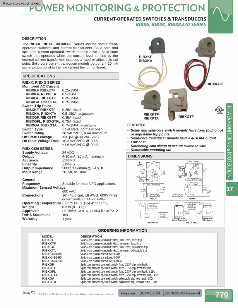
CURRENT-OPERATED SWITCHES & TRANSDUCERS RIBXG, RIBXK, RIBXK420 SERIES
RIBXK, RIBXG SERIESMonitored AC Current RIBXKF, RIBXKTF 0.25-150A RIBXKA, RIBXKTA 0.5-150A RIBXGF, RIBXGTF 0.35-150A RIBXGA, RIBXGTA 0.75-150ASwitch Trip Point RIBXKF, RIBXKTF 0.25A, fi xed RIBXKA, RIBXKTA 0.5-150A, adjustable RIBXGF, RIBXGTF 0.35A, fi xed RIBXGFL, RIBXGTFL 0.75A, fi xed RIBXGA, RIBXGTA 0.75-150A, adjustableSwitch Type Solid state, normally openSwitch rating 30 VAC/VDC, 0.4A maximumOff State Leakage <30 µA @ 30 VAC/VDCOn State Voltage Drop <0.3 VAC/VDC @ 0.1A <1.6 VAC/VDC @ 0.4ARIBXK420 SERIESSupply Voltage 24 VDCOutput 4-20 mA, 30 mA maximumAccuracy ±5% FSLinearity ±1% FSOutput Impedance 500Ω maximum @ 24 VDCInput Range 20, 50, or 100A
GeneralFrequency Suitable for most VFD applicationsMaximum Sensed Voltage
600 VACConnections 16" (40.6 cm), 18 AWG, 600V wires
or terminals for 14-22 AWGOperating Temperature -30° to 140°F (-34.4° to 60°C)Weight 0.3 lb (0.13 kg)Approvals UL listed, UL916, UL864 fi le #57312RoHS Statement YesWarranty 1 year
0.50(1.27)dia.
1.46(3.7)
1.86(4.73)
1.508(3.83)
1.008(2.56)
RatchetingCam
Clamp
RemovableMounting Tab
RIBXK420 RIBXK , RIBXG
RIBXK
in(cm)
24 VDCPower Supply
(black)
(red)BAS Inputor Other
4-20 mA Load
+ –
2.52 (6.4)
2.00(5.1)
1.10(2.8)
1.75(4.4)
Load Wire Opening0.52 x 0.52 (1.3 x 1.3)
OptionalLEDs
OptionalTrip
Adjust
Wire Clamp
RemovableMounting Tab
Wh/Yel
LoadWire
LoadWire
Wh/Yel
Wh/Yel
Normally opensolid-stateswitch is
not polaritysensitive
Models withScrew Terminals
Models withWire Leads
Wh/Yel
RIBXG
DESCRIPTION
The RIBXK, RIBXG, RIBXK420 Series include both current-operated switches and current transducers. Solid-core and split-core current-operated switch models have a solid-state switch that operates when the current level sensed by the internal current transformer exceeds a fi xed or adjustable set point. Solid-core current transducer models output a 4-20 mA signal proportional to the line current being monitored.
FEATURES
• Solid- and split-core switch models have fi xed (go/no go) or adjustable trip points
• Solid-core transducer models have a 4-20 mA output• Low cost• Ratcheting cam clamp to secure switch to wire• Removable mounting tab
LISTEDLISTED
MODEL DESCRIPTION RIBXKF Solid-core current-operated switch, wire leads, fi xed-trip RIBXKTF Solid-core current-operated switch, terminals, fi xed-trip RIBXKA Solid-core current-operated switch, wire leads, adjustable-trip RIBXKTA Solid-core current-operated switch, terminals, adjustable-trip RIBXK420-20 Solid-core current transducer, 0-20A RIBXK420-50 Solid-core current transducer, 0-50A RIBXK420-100 Solid-core current transducer, 0-100A RIBXGF Split-core current-operated switch, fi xed 0.35A trip, wire leads RIBXGTF Split-core current-operated switch, fi xed 0.35A trip, terminal strip RIBXGFL Split-core current-operated switch, fi xed 0.75A trip, wire leads, LEDs RIBXGTFL Split-core current-operated switch, fi xed 0.75A trip, terminal strip, LEDs RIBXGA Split-core current-operated switch, adjustable trip, wire leads, LEDs RIBXGTA Split-core current-operated switch, adjustable trip, terminal strip, LEDs
DIMENSIONS
SPECIFICATIONS
RIBXKFRIBXKA
RIBXGTF
RIBXK420
RIBXKTFRIBXKTA
January 2012

001-901-382-6084 International 888-397-5353 USA kele.com © 2012 Kele, Inc. All rights reserved. The Kele name and logo are registered trademarks of Kele, Inc.
POWER MONITORING & PROTECTION
780
POW
ER M
ON
ITO
RIN
G &
PRO
TECT
ION
17
CURRENT-OPERATED SWITCHES CS1A, CS1150A-LED, SCS1.5A, SCS1150A-LED
Frequency 6-100 Hz Switch Type Normally open, solid state (SC250-
NC is normally closed) Rating 1-135 VAC/VDC, 0.3A (SC250-NC
model 0.2A) Insulation Class 600V Trip Point CS1A Fixed, 1A SCS1.5A Fixed, 1.25A CS1150A Adjustable 1-200A SCS1150A, SC250-NC
Adjustable 1.25-200A Range CS1A, CS1150 1 - 200A, Jumper High SCS1.5A, SCS1150A, SC250-NC
1.25 - 200A, Jumper High Deadband 5% of setpoint Response Time Less than 250 milliseconds Off State Leakage < 25 mA Jumper None = 0-100A Mid = 0-150A High = 0-200A
Operating Temperature -22° to 158°F (-30° to 70°C) Mounting 3.5"L (8.9 cm) with 3.0" (7.6 cm)
mounting centers Dimensions
CS1A, CS1150 1.9 x 3.45 x 1 (4.82 x 8.76 x 2.54 cm) SCS1.5A, SCS1150A, SC250-NC
2.75 x 3.45 x 1.2 (6.98 x 8.76 x 3.04 cm)
Window Size CS1A, CS1150 0.75" (1.9 cm) dia, for up to 250
MCM cable SCS1.5A, SCS1150A, SC250-NC
0.85" (2.2 cm) square aperture, for up to 350 MCM cable
Weight 0.25 lb (0.11 kg) Approvals UL listed, File #E320368 CE certifi ed Warranty 1 year
DESCRIPTION
The Kele Models CS1A, SCS1.5A, CS1150A and SCS1150A are solid-state switches that operate when the AC current level sensed by the internal current transformer exceeds a fixed or adjustable trip point. Internal circuits are totally powered by induction from the conductor being monitored. There is zero off-state leakage current in the solid-state relay output that can switch AC or DC circuits. The Smart LED indication option eliminates the need for meters when setting the adjustable trip point of the current switch. Solid-core and split-core models are available.
FEATURES
• Models with fi xed or adjustable trip point• Switch AC or DC circuits• Power and status LED• Applicable for VFD applications down to 6Hz• Powered by monitored line• Available in solid-core models or split-core models that
clamp easily around cables• Five-year warranty• UL listed, CE certifi ed
SPECIFICATIONS
SCS1150A-LEDSCS1.5A
CS1150A-LEDCS1A
January 2012
© 2012 Kele, Inc. All rights reserved. The Kele name and logo are registered trademarks of Kele, Inc. kele.com 888-397-5353 USA 001-901-382-6084 International 781
POWER MONITORING & PROTECTIONPO
WER M
ON
ITORIN
G & PRO
TECTION
17
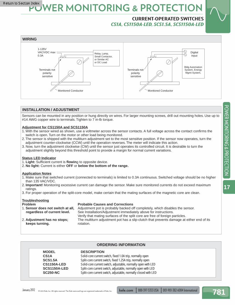
CURRENT-OPERATED SWITCHES CS1A, CS1150A-LED, SCS1.5A, SCS1150A-LED
Bldg Automation System, Energy Mgmt System,
1-135VVAC/VDC max0.3A
Relay, Lamp,Small Contactor,or Similar ACor DC Load
Terminals not polarity sensitive
DigitalInput
Terminals not polarity sensitive
Monitored Conductor Monitored Conductor
WIRING
INSTALLATION / ADJUSTMENT
ORDERING INFORMATION
MODEL DESCRIPTION CS1A Solid-core current switch, fi xed 1.0A trip, normally open SCS1.5A Split-core current switch, fi xed 1.25A trip, normally open CS1150A-LED Solid-core current switch, adjustable, normally open with LED SCS1150A-LED Split-core current switch, adjustable, normally open with LED SC250-NC Split-core current switch, adjustable, normally closed with LED
Sensors can be mounted in any position or hung directly on wires. For larger mounting screws, drill out mounting holes. Use up to #14 AWG copper wire to terminals. Tighten to 7 in-lb torque.
Adjustment for CS1150A and SCS1150A1. With the sensor wired as shown, use a voltmeter across the sensor contacts. A full voltage across the contact confi rms the
switch is open. Turn on the motor or other load being monitored.2. The sensor is shipped with the multiturn adjustment set to the most sensitive position. If the sensor now operates, turn the
adjustment counter-clockwise (CCW) until the operation reverses. The meter will indicate this action.3. Now, turn the adjustment clockwise (CW) until the sensor just operates its controlled circuit. It is desirable to turn the
adjustment slightly beyond this threshold point to provide a margin for normal current variations.
Status LED Indicator1. Light: Suffi cient current is fl owing to opposite device.2. No light: Current is either OFF or below the bottom of the range.
Application Notes1. Make sure that switched current (connected to terminals) is limited to 0.3A continuous. Switched voltage should be no higher
than 135 VAC/VDC.2. Important! Monitoring excessive current can damage the sensor. Make sure monitored currents do not exceed maximum
ratings.3. For proper operation of the split-core model, make certain that the mating surfaces of the magnetic core are clean.
TroubleshootingProblem Probable Causes and Corrections1. Sensor does not switch at all, Adjustment pot is probably backed off completely, which disables the sensor. regardless of current level. See Installation/Adjustment immediately above for instructions. Verify that mating surfaces of the split core are free of foreign particles.2. Adjustment has no stops; The multiturn adjustment pot has a slip-clutch that prevents damage at either end of its keeps turning. rotation.
January 2012

001-901-382-6084 International 888-397-5353 USA kele.com © 2012 Kele, Inc. All rights reserved. The Kele name and logo are registered trademarks of Kele, Inc.
POWER MONITORING & PROTECTION
782
POW
ER M
ON
ITO
RIN
G &
PRO
TECT
ION
17
ACI CURRENT-OPERATED SWITCHES A/ACS, A/ASCS, A/CS, A/SCS, A/CR SERIES
Supply Voltage Induced from monitored conductor Frequency 40 Hz to 1 kHz Outputs Normally Open 0.3A @ 200 VAC/
VDC Normally Closed 0.15A @ 300 VAC/VDC
Isolation Rating 1270 VAC Insulation 600 VAC LED Indication Red = Above trip point Green = Below trip point Deadband 10% Setpoint Operating Temperature 5° to 104°F (-15° to 40°C)
Operating Humidity 0 to 95% RH,(non-condensing) Mounting DIN rail (35 mm), screw Window Size 0.75" (1.9 cm), accepts up to 350
MCM cables Weight 0.21 lb (0.1 kg) Approvals UL and cUL listed, fi le #E309723 and
#E179139 CE RoHS Statement Yes Warranty 5 years, limited
DESCRIPTION
The ACI current switches are solid-state devices that operate when the sensed AC current level exceeds a fi xed or adjustable trip point. The A/CS Series is solid-core with a fi xed trip point. The A/SCS Series is split-core with a fi xed trip point. The A/ACS Series is solid-core with adjustable trip point. The A/ASCS Series is split-core with adjustable trip point. All models monitor either a 0-200 or 0-250 amp current fl ow in the wire and are available in normally-open or normally-closed confi gurations. The A/CR Series command relay brings control to monitoring applications.
FEATURES
• Available in solid or split-core• Fixed or adjustable trip points• Switches AC or DC circuits• Status LED's• Integral DIN rail mount• Powered by monitored line• Enclosure rated UL94-5VB• Pilot duty rated (A/CR Series)
.
LISTEDLISTED
SPECIFICATIONS
Model Relay Type Contact Rating Coil Voltage Coil Current
A/CR-DC-5A SPDT 5A 23-31.2 VDC 15mA @ 24 VDC
A/CR-DC-12A SPDT 12A 20-31.2 VDC 16mA @ 24 VDC
A/CR-12DC-12A SPDT 12A 10-15.6 VDC 30mA @ 12 VDC
A/CR-24AC-10A SPDT 10A 16-25.4 VAC 28mA @ 24 VAC
A/CR-115AC-8A SPDT 8A 80-132 VAC 10mA @ 115 VAC
A/CR-230AC-8A SPDT 8A 165-264 VAC 5mA @ 230 VAC
RELAY SPECIFICATIONS (COMMAND RELAY)
A/CR-D-12A
A/CS, A/ACS
A/SCS, A/ASCS
January 2012
© 2012 Kele, Inc. All rights reserved. The Kele name and logo are registered trademarks of Kele, Inc. kele.com 888-397-5353 USA 001-901-382-6084 International 783
POWER MONITORING & PROTECTIONPO
WER M
ON
ITORIN
G & PRO
TECTION
17
ACI CURRENT-OPERATED SWITCHES A/ACS, A/ASCS, A/CS, A/SCS, A/CR SERIES
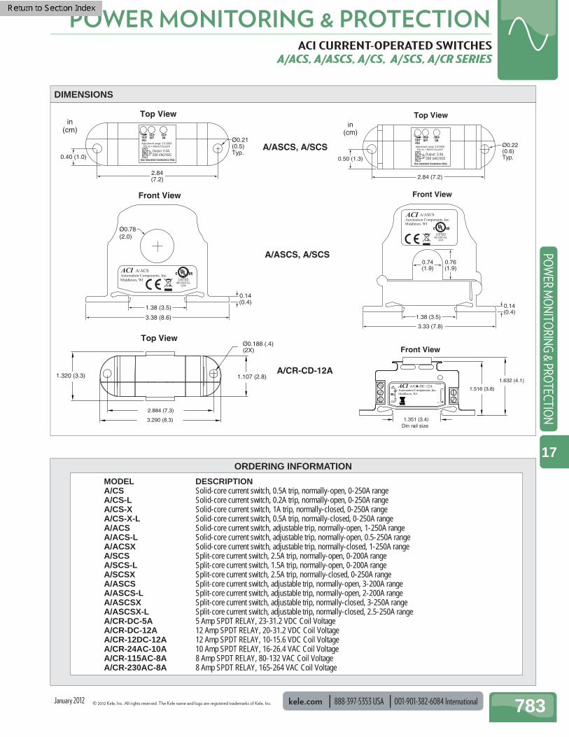
3.38 (8.6)
1.38 (3.5)
0.14(0.4)
2.84(7.2)
0.40 (1.0)
in(cm)
Ø0.21(0.5)Typ.
Ø0.78(2.0)
Front View
Top View
Trip on = Above trip pointAdjustment range: 3.0-200A
Use Insulated Conductors Only
Top ViewØ0.188 (.4)(2X)
1.107 (2.8)1.320 (3.3)
2.884 (7.3)
3.290 (8.3)
1.632 (4.1)
0.76(1.9)
0.74(1.9)
3.33 (7.8)
1.38 (3.5)
2.84 (7.2)
Front View
0.50 (1.3)
in(cm)
Ø0.22(0.6)Typ.
Top View
0.14(0.4)
Trip on = Above trip pointAdjustment range: 3.0-200A
Use Insulated Conductors Only
Front View
1.516 (3.8)
1.351 (3.4)Din rail size
A/ASCS, A/SCS
A/ASCS, A/SCS
A/CR-CD-12A
DIMENSIONS
ORDERING INFORMATION
MODEL DESCRIPTION A/CS Solid-core current switch, 0.5A trip, normally-open, 0-250A range A/CS-L Solid-core current switch, 0.2A trip, normally-open, 0-250A range A/CS-X Solid-core current switch, 1A trip, normally-closed, 0-250A range A/CS-X-L Solid-core current switch, 0.5A trip, normally-closed, 0-250A range A/ACS Solid-core current switch, adjustable trip, normally-open, 1-250A range A/ACS-L Solid-core current switch, adjustable trip, normally-open, 0.5-250A range A/ACSX Solid-core current switch, adjustable trip, normally-closed, 1-250A range A/SCS Split-core current switch, 2.5A trip, normally-open, 0-200A range A/SCS-L Split-core current switch, 1.5A trip, normally-open, 0-200A range A/SCSX Split-core current switch, 2.5A trip, normally-closed, 0-250A range A/ASCS Split-core current switch, adjustable trip, normally-open, 3-200A range A/ASCS-L Split-core current switch, adjustable trip, normally-open, 2-200A range A/ASCSX Split-core current switch, adjustable trip, normally-closed, 3-250A range A/ASCSX-L Split-core current switch, adjustable trip, normally-closed, 2.5-250A range A/CR-DC-5A 5 Amp SPDT RELAY, 23-31.2 VDC Coil Voltage A/CR-DC-12A 12 Amp SPDT RELAY, 20-31.2 VDC Coil Voltage A/CR-12DC-12A 12 Amp SPDT RELAY, 10-15.6 VDC Coil Voltage A/CR-24AC-10A 10 Amp SPDT RELAY, 16-26.4 VAC Coil Voltage A/CR-115AC-8A 8 Amp SPDT RELAY, 80-132 VAC Coil Voltage A/CR-230AC-8A 8 Amp SPDT RELAY, 165-264 VAC Coil Voltage
January 2012
001-901-382-6084 International 888-397-5353 USA kele.com © 2012 Kele, Inc. All rights reserved. The Kele name and logo are registered trademarks of Kele, Inc.
POWER MONITORING & PROTECTION
784
POW
ER M
ON
ITO
RIN
G &
PRO
TECT
ION
17
ORDERING INFORMATION
ACI MINI CURRENT-OPERATED SWITCHES A/MCS, A/MSCS, A/MCS-A, A/MSCS-A
Supply Voltage Induced by monitored conductor Frequency 50/60 Hz Rating A/MCS, A/MSCS 0.5 A continuous 36 VAC/VDC A/MCS-A, A/MSCS-A 1 A continuous 36 VAC/VDC Insulation Class 600 VAC Isolation Rating 2,200 VAC LED Indication Red = Above trip point Green = Below trip point Trip Point A/MCS Fixed 0.20A A/MCS-A 0.32 - 150A A/MSCS Fixed 0.55A A/MSCS-A 0.70 - 150A Range A/MCS 0.20 - 150A A/MCS-A 0.32 - 150A A/MSCS 0.55 - 150A
A/MSCS-A 0.70 - 150A Operating Temperature -22° to 140°F (-30° to 60°C) Operating Humidity 0 to 95% RH, (non condensing) Dimensions
A/MCS, A/MCS-A 2.50" x 1.96" x 0.95" (6.35 x 4.97 x 2.41 cm)
A/MSCS, A/MSCS-A 2.65" x 2.35" x 0.95" (6.73 x 5.08 x 2.43 cm)
Window Size A/MCS, A/MCS-A 0.55" (1.39 cm) dia., up to 1 AWG
cables A/MSCS, A/MSCS-A 0.53" (1.34 cm) dia., up to 1 AWG
cables Weight 0.21 lb (0.1 kg) Approvals UL and cUL, fi le #E309723, CE RoHS Statement Yes Warranty 5 years
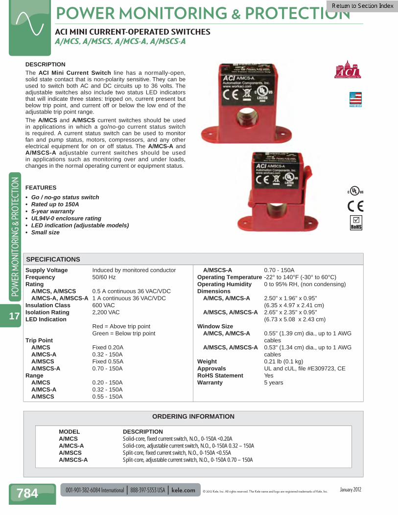
DESCRIPTION The ACI Mini Current Switch line has a normally-open, solid state contact that is non-polarity sensitive. They can be used to switch both AC and DC circuits up to 36 volts. The adjustable switches also include two status LED indicators that will indicate three states: tripped on, current present but below trip point, and current off or below the low end of the adjustable trip point range.The A/MCS and A/MSCS current switches should be used in applications in which a go/no-go current status switch is required. A current status switch can be used to monitor fan and pump status, motors, compressors, and any other electrical equipment for on or off status. The A/MCS-A and A/MSCS-A adjustable current switches should be used in applications such as monitoring over and under loads, changes in the normal operating current or equipment status.
FEATURES
• Go / no-go status switch• Rated up to 150A• 5-year warranty• UL94V-0 enclosure rating• LED indication (adjustable models)• Small size
.
MODEL DESCRIPTION A/MCS Solid-core, fi xed current switch, N.O., 0-150A <0.20A A/MCS-A Solid-core, adjustable current switch, N.O., 0-150A 0.32 – 150A A/MSCS Split-core, fi xed current switch, N.O., 0-150A <0.55A A/MSCS-A Split-core, adjustable current switch, N.O., 0-150A 0.70 – 150A
SPECIFICATIONS
January 2012
© 2012 Kele, Inc. All rights reserved. The Kele name and logo are registered trademarks of Kele, Inc. kele.com 888-397-5353 USA 001-901-382-6084 International 785
POWER MONITORING & PROTECTIONPO
WER M
ON
ITORIN
G & PRO
TECTION
17
ACI MINI CURRENT-OPERATED SWITCHES A/MCS, A/MSCS, A/MCS-A, A/MSCS-A
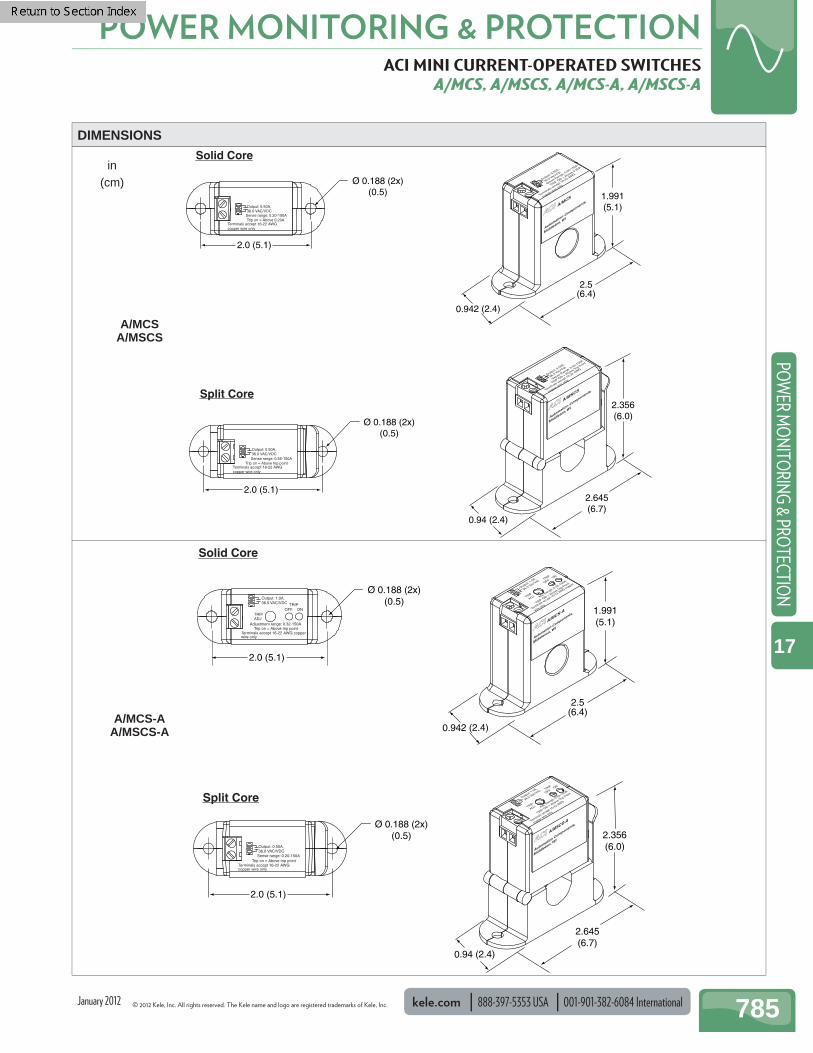
2.0 (5.1)
2.0 (5.1)
Ø 0.188 (2x)(0.5)
Ø 0.188 (2x)(0.5)
2.5(6.4)
1.991(5.1)
0.942 (2.4)
Solid Core
Split Core
2.645(6.7)
2.356(6.0)
0.94 (2.4)
Output: 0.50A,36.0 VAC/VDC
Trip on = Above 0.20ATerminals accept 16-22 AWGcopper wire only
Sense range: 0.20-150A
Output: 0.50A,
36.0 Vac/Vdc
TRIP ON = Above 0.20A
Terminals accept 1
6-22 AWG
copper wire
onlySense Range: 0.20-150A
Output: 0.50A,
36.0 Vac/Vdc
TRIP ON = Above Trip Point
Terminals accept 1
6-22 AWG
copper wire
onlySense Range: 0.55-150A
Output: 0.50A,36.0 VAC/VDC
Trip on = Above trip pointTerminals accept 16-22 AWGcopper wire only
Sense range: 0.55-150A
ACIACI A/M
CS
ACIACI A/M
SCS
Automation C
omponents,
Middleton, WI
Automation C
omponents,
Middleton, WI
DIMENSIONS
Output: 1.0A,36.0 VAC/VDC
Trip on = Above trip pointTerminals accept 16-22 AWG copperwire only
TRIPADJ
TRIPOFF ON
Adjustment range: 0.32-150A
TRIP ON = Above Trip Point
TRIP
ADJ
TRIP
OFFON
Terminals accept 16-22 AWG copper
wire only
Adj. Range: 0.32-150A
Output: 1.0A,
36.0 Vac/Vdc
ACIACI A/M
CS-A
ACIACI A/M
SCS-A
Automation Components,
Middleton, WI
Automation Components,
Middleton, WI
Output: 0.50A,36.0 VAC/VDC
Trip on = Above trip pointTerminals accept 16-22 AWGcopper wire only
Sense range: 0.20-150A
TRIP ON = Above Trip Point
TRIP
ADJ
TRIP
OFFON
Terminals accept 16-22 AWG
copper wire only
Adj. Range: 0.32-150A
Output: 1.0A,
36.0 Vac/Vdc
2.0 (5.1)
Ø 0.188 (2x)(0.5)
2.5(6.4)
1.991(5.1)
0.942 (2.4)
2.0 (5.1)
Ø 0.188 (2x)(0.5)
2.645(6.7)
2.356(6.0)
0.94 (2.4)
Solid Core
Split Core
A/MCSA/MSCS
A/MCS-AA/MSCS-A
January 2012
in(cm)

001-901-382-6084 International 888-397-5353 USA kele.com © 2012 Kele, Inc. All rights reserved. The Kele name and logo are registered trademarks of Kele, Inc.
POWER MONITORING & PROTECTION
786
POW
ER M
ON
ITO
RIN
G &
PRO
TECT
ION
17
Internal Current Sensing (for single-phase loads)Models with internal current-sensing are great for direct-control and current-sensing of exhaust fans, pumps, and other single-phase electrical loads up to 20A. The control relay contacts of these models wire directly in series with single-phase motors using the wires that exit the housing through the 1/2" conduit hub. The current of the load is sensed within the housing. Low-voltage wiring from the controller for the control relay coil and status switch enter the separate Class 2 wiring compartment in the housing through star bushings or conduit and are connected to screw terminals.
Remote Current Sensing (for loads with motor starters)Models with remote current-sensing are great for control and status sensing of electrical loads that require a motor starter. The control relay contacts of these models are wired in series with the motor starter coil using the two wires that exit the housing through the 1/2'' conduit hub. Currents up to 150A are sensed externally with a current sensing ring connected to the two gray wires that also exit through the 1/2'' conduit hub. Low-voltage wiring from the controller for the control relay coil and status switch enter the separate Class 2 wiring compartment in the housing through star bushings or conduit and are connected to screw terminals.
FUNCTIONAL DEVICES CURRENT SWITCH AND RELAY RIBX SERIES
DESCRIPTION
The Relay in a Box RIBX Series provides a unique and cost-effective solution to on/off motor control and current sensing status indication. Combined in a single, convenient junction box with high- and low-voltage separation are a control relay and a current sensing status switch. A three-position closed/open/auto switch is available to override the output of the relay. This versatile product allows both control and status sensing of electrical loads by a BAS, all in a self-contained, easy-to-install housing.
FEATURES
• Cost-effective current sensing with a control relay• Self-contained housing with high and low voltage
separation• LED indication of relay and current sensor trip• Optional relay contact override switch• Plenum-rated housing• UL and ULC listed for UL 916 Energy Management and
UL 864 Fire
APPLICATION
BAS ControllerStatus In
Control Out
Current is sensed internally.
RIBX
Optional Override SwitchClosed/Open/Auto
Single PhaseExhaust Fan
120-277 VAC10 or 20A
Class 2
Current Sensorand Control Relay
with Override Switch
On/Off
Internal Current Sensing
BAS ControllerStatus In
Control OutRIBX
Optional Override SwitchClosed/Open/Auto
Three-Phase Power
Class 2
On/Off
Contactor
MotorStarter
Relay Switches MotorStarter Coil
Current Sensorand Control Relay
with Override Switch
Toroid has no opencircuit voltage eliminatingelectrical shock hazard.
Three-PhaseMotorRemote Current Sensing
RIBX Split-CoreRemote Current
Sensing
RIBX Solid-CoreRemote Current
Sensing RIBX InternalCurrent Sensing
January 2012
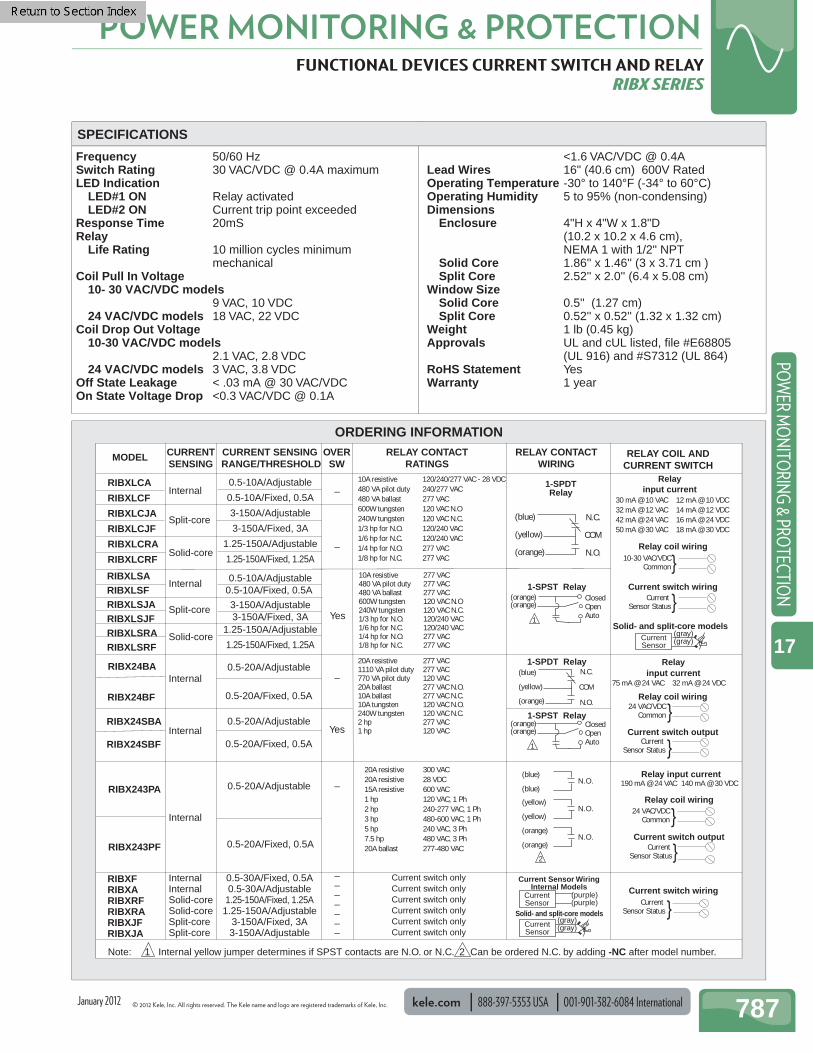
© 2012 Kele, Inc. All rights reserved. The Kele name and logo are registered trademarks of Kele, Inc. kele.com 888-397-5353 USA 001-901-382-6084 International 787
POWER MONITORING & PROTECTIONPO
WER M
ON
ITORIN
G & PRO
TECTION
17
FUNCTIONAL DEVICES CURRENT SWITCH AND RELAY RIBX SERIES
Frequency 50/60 Hz Switch Rating 30 VAC/VDC @ 0.4A maximum LED Indication LED#1 ON Relay activated LED#2 ON Current trip point exceeded Response Time 20mS Relay Life Rating 10 million cycles minimum
mechanical Coil Pull In Voltage 10- 30 VAC/VDC models
9 VAC, 10 VDC 24 VAC/VDC models 18 VAC, 22 VDC Coil Drop Out Voltage 10-30 VAC/VDC models
2.1 VAC, 2.8 VDC 24 VAC/VDC models 3 VAC, 3.8 VDC Off State Leakage < .03 mA @ 30 VAC/VDC On State Voltage Drop <0.3 VAC/VDC @ 0.1A
<1.6 VAC/VDC @ 0.4A Lead Wires 16" (40.6 cm) 600V Rated Operating Temperature -30° to 140°F (-34° to 60°C) Operating Humidity 5 to 95% (non-condensing) Dimensions
Enclosure 4"H x 4"W x 1.8"D (10.2 x 10.2 x 4.6 cm), NEMA 1 with 1/2" NPT
Solid Core 1.86'' x 1.46'' (3 x 3.71 cm )Split Core 2.52'' x 2.0'' (6.4 x 5.08 cm)
Window Size Solid Core 0.5'' (1.27 cm)Split Core 0.52'' x 0.52'' (1.32 x 1.32 cm)
Weight 1 lb (0.45 kg) Approvals UL and cUL listed, fi le #E68805
(UL 916) and #S7312 (UL 864) RoHS Statement Yes Warranty 1 year
SPECIFICATIONS
ORDERING INFORMATION
MODEL CURRENTSENSING
CURRENT SENSING RANGE/THRESHOLD
OVERSW
RELAY CONTACTWIRING
RELAY CONTACTRATINGS
RELAY COIL ANDCURRENT SWITCH
RIBXLCA
RIBXLCF
RIBXLCJA
RIBXLCJF
RIBXLCRA
RIBXLCRF
RIBXLSARIBXLSFRIBXLSJARIBXLSJFRIBXLSRARIBXLSRF
RIBX24SBA
RIBX24SBF
Internal
Internal
–
–
Yes
Yes
0.5-10A/Adjustable
0.5-10A/Fixed, 0.5A
3-150A/Adjustable
3-150A/Fixed, 3A
1.25-150A/Adjustable
1.25-150A/Fixed, 1.25A
Split-core
Solid-core
–0.5-20A/Adjustable
Internal
0.5-10A/Adjustable0.5-10A/Fixed, 0.5A
10A resistive 120/240/277 VAC - 28 VDC480 VA pilot duty 240/277 VAC480 VA ballast 277 VAC600W tungsten 120 VAC N.O240W tungsten 120 VAC N.C.1/3 hp for N.O. 120/240 VAC1/6 hp for N.C. 120/240 VAC1/4 hp for N.O. 277 VAC1/8 hp for N.C. 277 VAC
10A resistive 277 VAC480 VA pilot duty 277 VAC480 VA ballast 277 VAC600W tungsten 120 VAC N.O240W tungsten 120 VAC N.C.1/3 hp for N.O. 120/240 VAC1/6 hp for N.C. 120/240 VAC1/4 hp for N.O. 277 VAC1/8 hp for N.C. 277 VAC
20A resistive 277 VAC1110 VA pilot duty 277 VAC770 VA pilot duty 120 VAC20A ballast 277 VAC N.O.10A ballast 277 VAC N.C.10A tungsten 120 VAC N.O.240W tungsten 120 VAC N.C.2 hp 277 VAC1 hp 120 VAC
1-SPDTRelay
1-SPDT Relay
1-SPST Relay
1-SPST Relay
(blue)
(yellow)
(orange)
N.C.
COM
N.O.
(blue)
(yellow)
(orange)
N.C.
COM
N.O.
30 mA @ 10 VAC 12 mA @ 10 VDC 32 mA @ 12 VAC 14 mA @ 12 VDC42 mA @ 24 VAC 16 mA @ 24 VDC50 mA @ 30 VAC 18 mA @ 30 VDC
75 mA @ 24 VAC 32 mA @ 24 VDC
Current Sensor Status
10-30 VAC/VDCCommon
(orange)(orange)
ClosedOpenAuto
(orange)(orange)
ClosedOpenAuto
Note: 1 Internal yellow jumper determines if SPST contacts are N.O. or N.C. 2 Can be ordered N.C. by adding -NC after model number.
1
1
Relayinput current
Relayinput current
Relay coil wiring
Relay coil wiring
}
}
Current Sensor Status }
24 VAC/VDCCommon}
Split-core
Solid-core
3-150A/Adjustable3-150A/Fixed, 3A
1.25-150A/Adjustable
1.25-150A/Fixed, 1.25A
Internal
RIBX24BF
RIBXFRIBXARIBXRFRIBXRARIBXJFRIBXJA
InternalInternalSolid-coreSolid-coreSplit-coreSplit-core
0.5-30A/Fixed, 0.5A0.5-30A/Adjustable
1.25-150A/Fixed, 1.25A1.25-150A/Adjustable
3-150A/Fixed, 3A3-150A/Adjustable
–––––––
Current switch only Current switch only Current switch only Current switch only Current switch only Current switch only
RIBX24BA
0.5-20A/Fixed, 0.5A
0.5-20A/Adjustable
0.5-20A/Fixed, 0.5A
Current Sensor WiringInternal Models
(purple)(purple)
CurrentSensor
(gray)(gray)Current
Sensor
Solid- and split-core models
(gray)(gray)Current
Sensor
Solid- and split-core models
Current switch wiring
Current Sensor Status }
Current switch output
Current switch wiring
RIBX243PA
RIBX243PF
0.5-20A/Adjustable
0.5-20A/Fixed, 0.5A
–
Internal
20A resistive 300 VAC20A resistive 28 VDC15A resistive 600 VAC1 hp 120 VAC, 1 Ph2 hp 240-277 VAC, 1 Ph3 hp 480-600 VAC, 1 Ph5 hp 240 VAC, 3 Ph7.5 hp 480 VAC, 3 Ph20A ballast 277-480 VAC
(blue)
(blue)N.O.
(yellow)
(yellow)N.O.
(orange)
(orange)N.O.
2
190 mA @ 24 VAC 140 mA @ 30 VDCRelay input current
Current switch output
24 VAC/VDCCommon}Relay coil wiring
}Current Sensor Status
January 2012

001-901-382-6084 International 888-397-5353 USA kele.com © 2012 Kele, Inc. All rights reserved. The Kele name and logo are registered trademarks of Kele, Inc.
POWER MONITORING & PROTECTION
788
POW
ER M
ON
ITO
RIN
G &
PRO
TECT
ION
17
KELE AC CURRENT TRANSDUCER 4CTV, 4CMA
Supply Voltage 4CMA 24 VDC 4CTV Induced by monitored conductor Inputs 0-20A (change jumper to 0 to 50A) Outputs 4CMA 4-20 mA, 600Ω maximum load 4CTV 0-5 VDC, 30 kΩ minimum load Insulation Class 600V Ripple <2% FS Accuracy ±1% FS (24 VDC @ 25°C) Operating Temperature -22° to 158°F (-30° to 70°C) Dimensions 2.9" x 1" x 2.45"
(7.4 x 2.5 x .6.2 cm) Weight 0.25 lb (0.11 kg) Approvals UL File# E320368, CE RoHS Statement Yes Warranty 1 year
3.45 (8.7)
2.4 (6.0)
0.8(2.0)
1 (2.5)
1.95(4.9)
0.95 (2.4)
1.5 (3.9)3.08 (7.8)
1.0(2.5)
0.17(0.45)
Solid-Core
DESCRIPTIONModels 4CTV and 4CMA are AC amperage-to-analog DC transducers that can be used to directly monitor loads of up to 20A. For loads of 20-5000A, an external current transformer can be used. Developed for building automation and energy management, the Model 4CTV converts an AC current to a 0-5 VDC voltage and the Model 4CMA converts an AC current to a 4-20 mA current that can be monitored by any processor that accepts analog DC voltage or current.
FEATURES• 4CTV requires no external power supply• Rugged design to withstand momentary AC inrushes
of 120A (6x rating)• Easy to install, only two connections• 50/60 Hz operation
DIMENSIONSSPECIFICATIONS
4CTV
APPLICATION• AC current input to DC voltage or milliamp output• Monitoring of AC current of motors, lighting, heating,
industrial processes, etc.• Monitoring of chiller loads using existing current
transformers
4CMA
January 2012
in(cm)
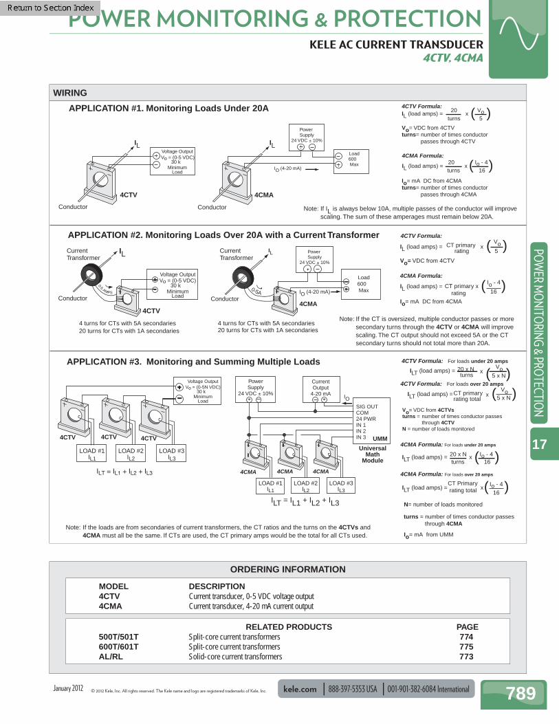
© 2012 Kele, Inc. All rights reserved. The Kele name and logo are registered trademarks of Kele, Inc. kele.com 888-397-5353 USA 001-901-382-6084 International 789
POWER MONITORING & PROTECTIONPO
WER M
ON
ITORIN
G & PRO
TECTION
17
ORDERING INFORMATION
KELE AC CURRENT TRANSDUCER 4CTV, 4CMA
4CTV Formula:IL (load amps) =
20 Voturns 5
x ( )Vo= VDC from 4CTVturns= number of times conductor passes through 4CTV
APPLICATION #1. Monitoring Loads Under 20A
Note: If IL is always below 10A, multiple passes of the conductor will improve scaling. The sum of these amperages must remain below 20A.
APPLICATION #2. Monitoring Loads Over 20A with a Current Transformer
Note: If the CT is oversized, multiple conductor passes or more secondary turns through the 4CTV or 4CMA will improve scaling. The CT output should not exceed 5A or the CT secondary turns should not total more than 20A.
4CTV Formula:
IL (load amps) = 5
x ( )Vo= VDC from 4CTV
CT primary rating
Vo
APPLICATION #3. Monitoring and Summing Multiple Loads
Note: If the loads are from secondaries of current transformers, the CT ratios and the turns on the 4CTVs and 4CMA must all be the same. If CTs are used, the CT primary amps would be the total for all CTs used.
4CTV Formula: For loads under 20 amps
ILT (load amps) = 5 x N
x ( )
Vo= VDC from 4CTVsturns = number of times conductor passes through 4CTVN = number of loads monitored
20 x N turns
Vo
4CTV Formula: For loads over 20 amps
ILT (load amps) = x ( )CT primaryrating total
Vo5 x N
Conductor
4CTV
4CTV
LOAD #1IL1
LOAD #2IL2
LOAD #3IL3
4CTV 4CTV 4CTV
CurrentTransformer
IL
0-5 AMPS
Conductor
CurrentTransformer
4CTV
4 turns for CTs with 5A secondaries20 turns for CTs with 1A secondaries
Power Supply
24 VDC ± 10%
IO (4-20 mA)
4CMA
Conductor
Load600�Max
Vo = (0-5 VDC)30 k�
Io= mA from UMM
N= number of loads monitored
4CMA Formula: For loads under 20 amps
ILT (load amps) = 20 x N Io - 4turns 16
x ( )
ILT (load amps) = Io - 4
16
CT Primary rating total x( )
4CMA Formula: For loads over 20 amps
turns = number of times conductor passes through 4CMA
4CMA Formula:
IL (load amps) = Io - 4
16( )Io= mA DC from 4CMA
CT primary x ratingIO (4-20 mA)
Power Supply
24 VDC ± 10%
IL
4CMA
4 turns for CTs with 5A secondaries20 turns for CTs with 1A secondaries
0-5A Conductor
Load600�Max
4CMA Formula:
IL (load amps) = 20 Io - 4turns 16
x ( )Io= mA DC from 4CMAturns= number of times conductor passes through 4CMA
IL IL
PowerSupply
24 VDC ± 10%
CurrentOutput
4-20 mA
SIG OUTCOM24 PWRIN 1IN 2IN 3 UMM
ILT = IL1 + IL2 + IL3
IO
UniversalMath
Module
LOAD #1IL1
LOAD #2IL2
LOAD #3IL3
4CMA 4CMA
MinimumLoad
Voltage Output
Vo = (0-5 VDC)30 k�
MinimumLoad
Voltage Output
Vo = (0-5N VDC)30 k�
MinimumLoad
Voltage Output
4CMA
WIRING
MODEL DESCRIPTION 4CTV Current transducer, 0-5 VDC voltage output 4CMA Current transducer, 4-20 mA current output
January 2012
RELATED PRODUCTS PAGE 500T/501T Split-core current transformers 774 600T/601T Split-core current transformers 775 AL/RL Solid-core current transformers 773

001-901-382-6084 International 888-397-5353 USA kele.com © 2012 Kele, Inc. All rights reserved. The Kele name and logo are registered trademarks of Kele, Inc.
POWER MONITORING & PROTECTION
790
POW
ER M
ON
ITO
RIN
G &
PRO
TECT
ION
17
ORDERING INFORMATION
AC CURRENT TRANSDUCER WITH CURRENT OUTPUT CX, SCX SERIES (CURRENT)
Frequency 10-400 Hz Output 4-20 mA Output Impedance 500Ω maximum @ 24 VDC Isolation Rating 1270 VAC Accuracy ±1% FS Response Time 250 ms, 0-90% Internal Protection Reverse voltage protection Overrange Limit Sensor self-limits output to 40 mA Operating Temperature -22° to 158°F (-30° to 70°C) Materials Of Construction
Thermoplastic (meets UL fl ammability rating 94V-0)
Weight 0.25 lb (0.11 kg) Approvals UL and ULC listed, File #E320368,
CE RoHS Statement Yes Warranty 5 years
2.75(7.0)
2.4 (6.10)3.45 (8.7)
0.85 (2.18)
0.85(2.18)
3.04 (7.73)
1.2(3.05)
3.45 (8.7)
2.4 (6.0)
0.8(2.0)
1 (2.5)
1.95(4.9)
0.95 (2.4)
1.5 (3.9)3.08 (7.8)
1.0(2.5)
0.17(0.45)
Split-Core Solid-Core
DESCRIPTION
The Kele CX/SCX Series AC Current Transducers can be used to directly monitor up to 200 amps and output a 4-20 mA signal. Available in a split-core design that allows for easy installation of the transducer on existing wiring or in a lower cost solid-core version.
FEATURES
• May eliminate the need for a current transformer • Small size• Loop powered• Easily installed over existing cable with split-core
design• UL listed, CE certifi ed
+
–4-20 mA
Load
PowerSupply
500Ω max@24 VDC
24 VDCTypical
–+
+ –
Monitored Conductor
WIRING
MODEL DESCRIPTION CX42050 Solid-core current transducer, 0-50A, 4-20 mA output CX420200 Solid-core current transducer, 0-200A, 4-20 mA output SCX42050 Split-core current transducer, 0-50A, 4-20 mA output SCX420200 Split-core current transducer, 0-200A, 4-20 mA output
DIMENSIONSSPECIFICATIONS
CX42050 SCX42050
CX420200SCX420200
MODEL RANGE JUMPER MAX CONT (amps) (amps)
CX42050 0-10 None 80 SCX42050 0-20 Mid 120 0-50 High 200
CX420200 0-100 None 175 SCX420200 0-150 Mid 300 0-200 High 400
January 2012
in(cm)
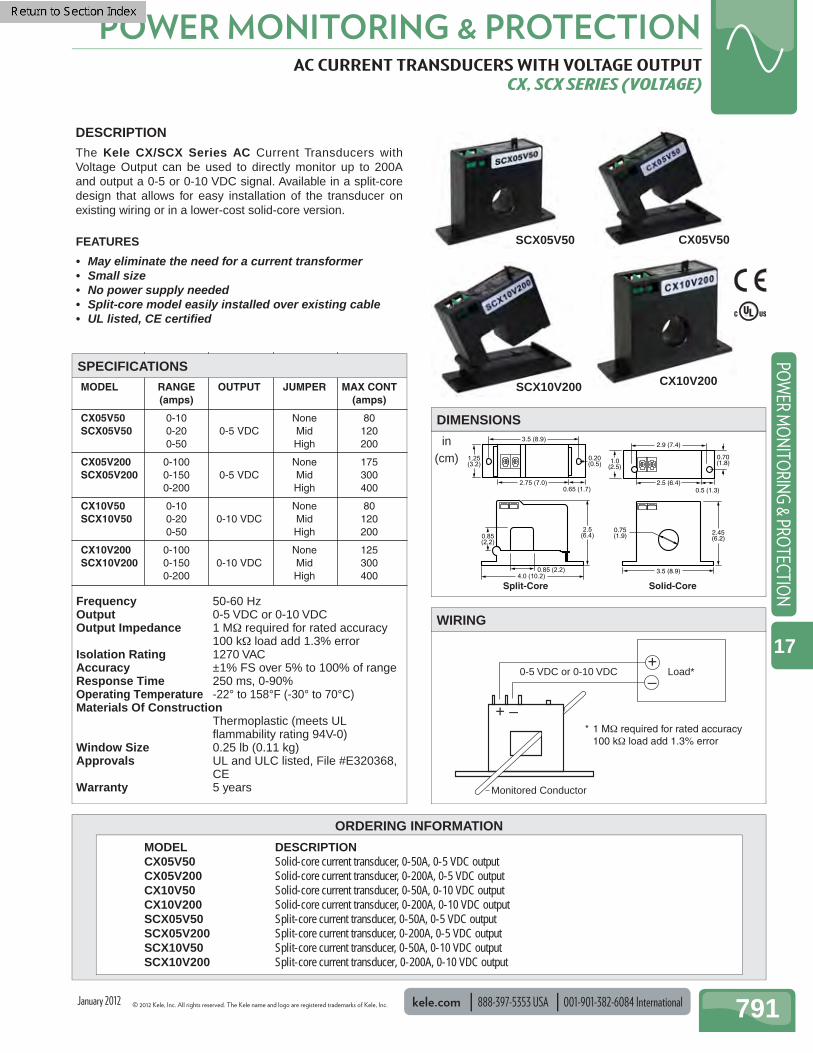
© 2012 Kele, Inc. All rights reserved. The Kele name and logo are registered trademarks of Kele, Inc. kele.com 888-397-5353 USA 001-901-382-6084 International 791
POWER MONITORING & PROTECTIONPO
WER M
ON
ITORIN
G & PRO
TECTION
17
Frequency 50-60 Hz Output 0-5 VDC or 0-10 VDC Output Impedance 1 MΩ required for rated accuracy
100 kΩ load add 1.3% error Isolation Rating 1270 VAC Accuracy ±1% FS over 5% to 100% of range Response Time 250 ms, 0-90% Operating Temperature -22° to 158°F (-30° to 70°C) Materials Of Construction
Thermoplastic (meets UL fl ammability rating 94V-0)
Window Size 0.25 lb (0.11 kg) Approvals UL and ULC listed, File #E320368,
CE Warranty 5 years
MODEL RANGE OUTPUT JUMPER MAX CONT (amps) (amps)
CX05V50 0-10 None 80SCX05V50 0-20 0-5 VDC Mid 120 0-50 High 200
CX05V200 0-100 None 175SCX05V200 0-150 0-5 VDC Mid 300 0-200 High 400
CX10V50 0-10 None 80SCX10V50 0-20 0-10 VDC Mid 120 0-50 High 200
CX10V200 0-100 None 125SCX10V200 0-150 0-10 VDC Mid 300 0-200 High 400
ORDERING INFORMATION
AC CURRENT TRANSDUCERS WITH VOLTAGE OUTPUT CX, SCX SERIES (VOLTAGE)
4.0 (10.2)
2.5(6.4)0.85
(2.2)
0.85 (2.2)
0.20(0.5)
3.5 (8.9)
2.75 (7.0)0.65 (1.7)
1.25(3.2)
2.45(6.2)
3.5 (8.9)
0.75(1.9)
2.9 (7.4)
0.70(1.8)
0.5 (1.3)2.5 (6.4)
1.0(2.5)
Split-Core Solid-Core
DESCRIPTION The Kele CX/SCX Series AC Current Transducers with Voltage Output can be used to directly monitor up to 200A and output a 0-5 or 0-10 VDC signal. Available in a split-core design that allows for easy installation of the transducer on existing wiring or in a lower-cost solid-core version.
FEATURES
• May eliminate the need for a current transformer • Small size • No power supply needed • Split-core model easily installed over existing cable • UL listed, CE certifi ed
+ –
0-5 VDC or 0-10 VDC Load*+ –
Monitored Conductor
WIRING
MODEL DESCRIPTION CX05V50 Solid-core current transducer, 0-50A, 0-5 VDC output CX05V200 Solid-core current transducer, 0-200A, 0-5 VDC output CX10V50 Solid-core current transducer, 0-50A, 0-10 VDC output CX10V200 Solid-core current transducer, 0-200A, 0-10 VDC output SCX05V50 Split-core current transducer, 0-50A, 0-5 VDC output SCX05V200 Split-core current transducer, 0-200A, 0-5 VDC output SCX10V50 Split-core current transducer, 0-50A, 0-10 VDC output SCX10V200 Split-core current transducer, 0-200A, 0-10 VDC output
DIMENSIONS
SPECIFICATIONS
SCX05V50
SCX10V200
CX05V50
CX10V200
January 2012
in(cm)
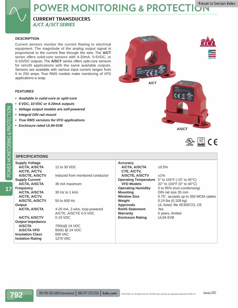
001-901-382-6084 International 888-397-5353 USA kele.com © 2012 Kele, Inc. All rights reserved. The Kele name and logo are registered trademarks of Kele, Inc.
POWER MONITORING & PROTECTION
792
POW
ER M
ON
ITO
RIN
G &
PRO
TECT
ION
17
CURRENT TRANSDUCERS A/CT, A/SCT SERIES
Supply Voltage A/CTA, A/SCTA 12 to 30 VDC A/CTE, A/CTV, A/SCTE, A/SCTV Induced from monitored conductor Supply Current A/CTA, A/SCTA 36 mA maximum Frequency A/CTA, A/SCTA 30 Hz to 1 kHz A/CTE, A/CTV, A/SCTE, A/SCTV 50 to 600 Hz Output A/CTA, A/SCTA 4-20 mA, 2-wire, loop-powered A/CTE, A/SCTE 0-5 VDC A/CTV, A/SCTV 0-10 VDC Output Impedance A/SCTA 700Ω@ 24 VDC A/SCTA-VFD 650Ω @ 24 VDC Insulation Class 600 VAC Isolation Rating 1270 VAC
Accuracy A/CTA, A/SCTA ±0.5% CTE, A/CTV, A/SCTE, A/SCTV ±1%
Operating Temperature 5° to 104°F (-15° to 40°C) VFD Models 32° to 104°F (0° to 40°C)
Operating Humidity 0 to 95% (non-condensing) Mounting DIN rail size 35 mm Window Size 0.75", accepts up to 350 MCM cables Weight 0.24 lbs (0.109 kg) Approvals UL listed, fi le #E309723, CERoHS Statement Yes Warranty 5 years, limited Enclosure Rating UL94-5VB
DESCRIPTION
Current sensors monitor the current flowing to electrical equipment. The magnitude of the analog output signal is proportional to the current fl ow through the wire. The A/CTseries offers solid-core sensors with 4-20mA, 0-5VDC, or 0-10VDC outputs. The A/SCT series offers split-core sensors for retrofit applications with the same available outputs. Sensors are available with various input current ranges from 5 to 250 amps. True RMS models make monitoring of VFD applications a snap.
FEATURES
• Available in solid-core or split-core
• 5 VDC, 10 VDC or 4-20mA outputs
• Voltage output models are self-powered
• Integral DIN rail mount
• True RMS versions for VFD applications
• Enclosure rated UL94-5VB
.
LISTEDLISTED
SPECIFICATIONS
A/CT
A/SCT
January 2012
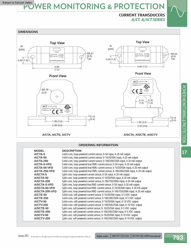
© 2012 Kele, Inc. All rights reserved. The Kele name and logo are registered trademarks of Kele, Inc. kele.com 888-397-5353 USA 001-901-382-6084 International 793
POWER MONITORING & PROTECTIONPO
WER M
ON
ITORIN
G & PRO
TECTION
17
ORDERING INFORMATION
CURRENT TRANSDUCERS A/CT, A/SCT SERIES
3.38 (8.6)
1.38 (3.5)
0.14(0.4)
2.84(7.2)
0.40 (1.0)
in(cm)
Ø0.21(0.5)Typ.
Ø0.78(2.0)
Front View
Top View
DIMENSIONS
MODEL DESCRIPTION A/CTA-5 Solid-core, loop-powered current sensor, 0-5A input, 4-20 mA output A/CTA-50 Solid-core, loop-powered current sensor, 0-10/20/50A input, 4-20 mA output A/CTA-250 Solid-core, loop-powered current sensor, 0-100/200/250A input, 4-20 mA output A/CTA-5-VFD Solid-core, loop-powered true RMS current sensor, 0-5A input, 4-20 mA output A/CTA-50-VFD Solid-core, loop-powered true RMS current sensor, 0-10/20/50A input, 4-20 mA output A/CTA-250-VFD Solid-core, loop-powered true RMS current sensor, 0-100/200/250A input, 4-20 mA output A/SCTA-5 Split-core, loop-powered current sensor, 0-5A input, 4-20 mA output A/SCTA-50 Split-core, loop-powered current sensor, 0-10/20/50A input, 4-20 mA output A/SCTA-200 Split-core, loop-powered current sensor, 0-100/150/200A input, 4-20 mA output A/SCTA-5-VFD Split-core, loop-powered true RMS current sensor, 0-5A input, 4-20 mA output A/SCTA-50-VFD Split-core, loop-powered true RMS current sensor, 0-10/20/50A input, 4-20 mA output A/SCTA-200-VFD Split-core, loop-powered true RMS current sensor, 0-100/150/200A input, 4-20 mA output A/CTE-50 Solid-core, self-powered current sensor, 0-10/20/50A input, 0-5 VDC output A/CTE-250 Solid-core, self-powered current sensor, 0-100/200/250A input, 0-5 VDC output A/CTV-50 Solid-core, self-powered current sensor, 0-10/20/50A input, 0-10 VDC output A/CTV-250 Solid-core, self-powered current sensor, 0-100/200/250A input, 0-10 VDC output A/SCTE-50 Split-core, self-powered current sensor, 0-10/20/50A input, 0-5 VDC output A/SCTE-250 Split-core, self-powered current sensor, 0-100/200/250A input, 0-5 VDC output A/SCTV-50 Split-core, self-powered current sensor, 0-10/20/50A input, 0-10 VDC output A/SCTV-250 Split-core, self-powered current sensor, 0-100/200/250A input, 0-10 VDC output
0.76(1.9)
0.74(1.9)
3.33 (3.8)
1.38 (3.5)
2.84 (7.2)
Front View
0.50 (1.3)
in(cm)
Ø0.22(0.6)Typ.
Top View
0.14(0.4)
A/CTA, A/CTE, A/CTV A/SCTA, A/SCTE, A/SCTV
January 2012
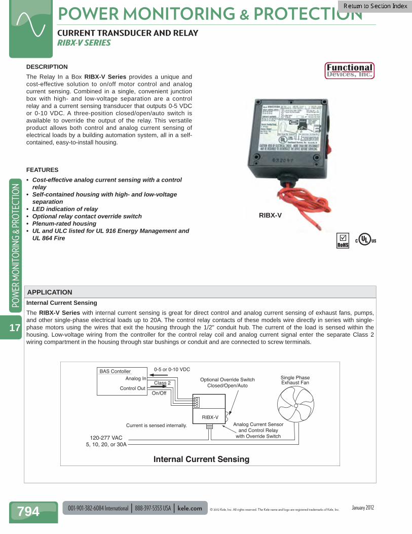
001-901-382-6084 International 888-397-5353 USA kele.com © 2012 Kele, Inc. All rights reserved. The Kele name and logo are registered trademarks of Kele, Inc.
POWER MONITORING & PROTECTION
794
POW
ER M
ON
ITO
RIN
G &
PRO
TECT
ION
17
CURRENT TRANSDUCER AND RELAY RIBX-V SERIES
DESCRIPTION
The Relay In a Box RIBX-V Series provides a unique and cost-effective solution to on/off motor control and analog current sensing. Combined in a single, convenient junction box with high- and low-voltage separation are a control relay and a current sensing transducer that outputs 0-5 VDC or 0-10 VDC. A three-position closed/open/auto switch is available to override the output of the relay. This versatile product allows both control and analog current sensing of electrical loads by a building automation system, all in a self-contained, easy-to-install housing.
FEATURES
• Cost-effective analog current sensing with a control relay
• Self-contained housing with high- and low-voltage separation
• LED indication of relay• Optional relay contact override switch• Plenum-rated housing• UL and ULC listed for UL 916 Energy Management and
UL 864 Fire
APPLICATION
RIBX-V
Internal Current Sensing
The RIBX-V Series with internal current sensing is great for direct control and analog current sensing of exhaust fans, pumps, and other single-phase electrical loads up to 20A. The control relay contacts of these models wire directly in series with single-phase motors using the wires that exit the housing through the 1/2" conduit hub. The current of the load is sensed within the housing. Low-voltage wiring from the controller for the control relay coil and analog current signal enter the separate Class 2 wiring compartment in the housing through star bushings or conduit and are connected to screw terminals.
BAS ContollerAnalog In
Control Out
Current is sensed internally.
RIBX-V
Optional Override SwitchClosed/Open/Auto
Single PhaseExhaust Fan
120-277 VAC5, 10, 20, or 30A
Class 2
0-5 or 0-10 VDC
Analog Current Sensorand Control Relay
with Override Switch
On/Off
Internal Current Sensing
January 2012
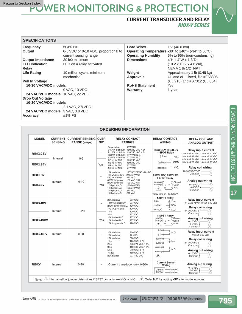
© 2012 Kele, Inc. All rights reserved. The Kele name and logo are registered trademarks of Kele, Inc. kele.com 888-397-5353 USA 001-901-382-6084 International 795
POWER MONITORING & PROTECTIONPO
WER M
ON
ITORIN
G & PRO
TECTION
17
CURRENT TRANSDUCER AND RELAY RIBX-V SERIES
Frequency 50/60 Hz Output 0-5 VDC or 0-10 VDC, proportional to
current sensing range Output Impedance 30 kΩ minimum LED Indication LED on = relay activated RelayLife Rating 10 million cycles minimum
mechanical Pull In Voltage 10-30 VAC/VDC models
9 VAC, 10 VDC 24 VAC/VDC models 18 VAC, 22 VDC Drop Out Voltage 10-30 VAC/VDC models
2.1 VAC, 2.8 VDC 24 VAC/VDC models 3 VAC, 3.8 VDC Accuracy ±1% FS
Lead Wires 16" (40.6 cm) Operating Temperature -30° to 140°F (-34° to 60°C) Operating Humidity 5% to 95% (non-condensing) Dimensions 4"H x 4"W x 1.8"D
(10.2 x 10.2 x 4.6 cm), NEMA 1 th 1/2" NPT
Weight Approximately 1 lb (0.45 kg) Approvals UL and cUL listed, fi le #E68805
(UL 916) and #S7312 (UL 864) RoHS Statement Yes Warranty 1 year
SPECIFICATIONS
ORDERING INFORMATION
MODEL CURRENTSENSING
CURRENT SENSING RANGE (amps)
OVERSW
RELAY CONTACTWIRING
RELAY CONTACTRATINGS
RELAY COIL ANDANALOG OUTPUT
RIBXLCEV
RIBXLSEV
RIBXLCV
RIBXLSV
RIBX24BV
RIBX24SBV
RIBXV
Internal
InternalYes
Yes
0-5
0-30
0-10
Internal
–
–
0-20
Internal
RIBX243PV 0-20 –Internal
10A resistive 120/240/277 VAC - 28 VDC480 VA pilot duty 240/277 VAC480 VA ballast 277 VAC600W tungsten 120 VAC N.O240W tungsten 120 VAC N.C.1/3 hp for N.O. 120/240 VAC1/6 hp for N.C. 120/240 VAC1/4 hp for N.O. 277 VAC1/8 hp for N.C. 277 VAC
5A resistive 277 VAC345 VA pilot duty 120/240 VAC N.O.211 VA pilot duty 120/240 VAC N.C.268 VA pilot duty 277 VAC N.O.175 VA pilot duty 277 VAC N.C.1/3 hp for N.O. 120/240 VAC1/6 hp for N.C. 120/240 VAC1/4 hp for N.O. 277 VAC1/8 hp for N.C. 277 VAC
20A resistive 277 VAC1110 VA pilot duty 277 VAC240W tungsten N.C. 120 VAC770 VA pilot duty 120 VAC1 hp 120 VAC2 hp 277 VAC20A ballast N.O. 277 VAC10A ballast N.C. 277 VAC10A tungsten N.O. 120 VAC
20A resistive 300 VAC20A resistive 28 VDC15A resistive 600 VAC1 hp 120 VAC, 1 Ph2 hp 240-277 VAC, 1 Ph3 hp 480-600 VAC, 1 Ph5 hp 240 VAC, 3 Ph7.5 hp 480 VAC, 3 Ph20A ballast 277-480 VAC
RIBXLCEV, RIBXLCV1-SPDT Relay
1-SPDT Relay
RIBXLSEV, RIBXLSV1-SPST Relay
1-SPST Relay
(blue)
(yellow)
(orange)
N.C.
COM
N.O.
(blue)
(yellow)
(orange)
N.C.
COM
N.O.
(blue)
(blue)N.O.
(yellow)
(yellow)N.O.
(orange)
(orange)N.O.
30 mA @ 10 VAC 12 mA @ 10 VDC 32 mA @ 12 VAC 14 mA @ 12 VDC42 mA @ 24 VAC 16 mA @ 24 VDC50 mA @ 30 VAC 18 mA @ 30 VDC
75 mA @ 24 VAC, 32 mA @ 24 VDC
(orange)*(orange)*
ClosedOpenAuto
(orange)(orange)
ClosedOpenAuto
Internal yellow jumper determines if SPST contacts are N.O. or N.C. Order N.C. by adding -NC after model number.
1
1
2
Relay input current
Relay input current
0-10 VDC0-5 VDCCommon
Analog out wiring
}
Analog out wiring
10-30 VAC/VDCCommon}
24 VAC/VDCCommon}
Current transducer only, 0-30A
–
–
Note:
Yes
*Gray wire on RIBXLSEV
Current SensorWiring
(purple)(purple)
CurrentSensor
Relay coil wiring
Relay coil wiring
}0-10 VDC
0-5 VDCCommon
190 mA @ 24 VACRelay input current
Analog out wiring
24 VAC/VDCCommon}Relay coil wiring
}0-10 VDCCommon
}0-10 VDC
0-5 VDCCommon
Analog out wiring
21
January 2012

001-901-382-6084 International 888-397-5353 USA kele.com © 2012 Kele, Inc. All rights reserved. The Kele name and logo are registered trademarks of Kele, Inc.
POWER MONITORING & PROTECTION
796
POW
ER M
ON
ITO
RIN
G &
PRO
TECT
ION
17
Supply Voltage 24 - 40 VDC Frequency 50 - 60 Hz V Models 10 - 400 Hz Output 4 - 20 mA, loop-powered Output Impedance 600Ω max @ 24 VDC Insulation Class 600 VAC Accuracy 1.0% FS Response Time 500 ms to 90% of step change Overrange Limit Sensor self-limits to 25 mA output Terminations Screw terminals Materials Of Construction
UL 94 fl ammability rated thermoplastic
Weight 1.3 lb (0.6 kg) Approvals UL and ULC listed, File # E129625,
CE certifi ed Warranty 5 years
ORDERING INFORMATION
HIGH AC CURRENT TRANSDUCERS WITH CURRENT OUTPUT SENTRY 200-A SERIES
Aperture3
(7.63)4.22(10.7)
4.5(11.43)
in(cm)
1.9(4.83)Depth
DESCRIPTION
The Sentry 200-A Series High AC Current Transducers with Current Output can be used to directly monitor up to 2000A without requiring an additional current transformer. The output from these transducers is a 4-20 mA signal.
FEATURES
• Eliminates the need for a current transformer• Large aperture to accommodate large conductors or
wire bundles• Loop powered 4-20 mA output• Multi-range input eliminates zero and span
adjustments• Easy installation with integral mounting brackets
+
–
4-20 mA
Load
PowerSupply 24 VDC
Typical
–+
+ -
Sentry200-A
Monitored Conductor
WIRING
DIMENSIONS
SPECIFICATIONS 200-3-A
MODEL DESCRIPTION 200-3-A Solid-core high current transducer, 0-750A, 4-20 mA output 200-3-A-V Solid-core high current transducer, 0-750A, 4-20 mA output (10 - 400 Hz) 200-4-A Solid-core high current transducer, 0-2000A, 4-20 mA output 200-4-A-V Solid-core high current transducer, 0-2000A, 4-20 mA output (10 -400 Hz)
MODEL RANGE SWITCH MAX CONT MAX FOR MAX FOR POSITION 6 SEC 1 SEC (amps)200-3-A 0-375 375 750 1500 3750 0-500 500 0-750 750200-4-A 0-1000 1000 2000 4000 10,000 0-1333 1333 0-2000 2000
Note: The standard models are average responding. Also available are variable frequency integration models for monitoring the load side of a VFD.
January 2012

© 2012 Kele, Inc. All rights reserved. The Kele name and logo are registered trademarks of Kele, Inc. kele.com 888-397-5353 USA 001-901-382-6084 International 797
POWER MONITORING & PROTECTIONPO
WER M
ON
ITORIN
G & PRO
TECTION
17
MISCELLANEOUS TRANSFORMERSMODELS 189, 190XSUM, 3PT3, CTW3, 468
189
MODEL DESCRIPTION 189-005 5:5 Ratio CT secondary isolation transformer
MODEL 189 ISOLATION CURRENT TRANSFORMER
190XSUM
MODEL DESCRIPTION 190XSUM2 Summing transformer for 2 CT's 0-5A output 190XSUM3 Summing transformer for 3 CT's 0-5A output 190XSUM4 Summing transformer for 4 CT's 0-5A output 190XSUM5 Summing transformer for 5 CT's 0-5A output
MODEL 190XSUM SUMMING CURRENT TRANSFORMER
3PT3
MODEL DESCRIPTION CTW3-60-T50-100 5kV single phase current transformer 10:5A CTW3-60-T50-200 5kV single phase current transformer 20:5A CTW3-60-T50-500 5kV single phase curretn transformer 50:5A CTW3-60-T50-101 5kV single phase current transformer 100:5A CTW3-60-T50-201 5kV single phase current transformer 200:5A CTW3-60-T50-301 5kV single phase current transformer 300:5A CTW3-60-T50-401 5kV single phase current transformer 400:5A CTW3-60-T50-501 5kV single phase current transformer 500:5A
MODEL CTW3 CURRENT TRANSFORMER
MODEL DESCRIPTION 468-208 600V single phase potential transformer 208:120V 468-240 600V single phase potential transformer 240:120V 468-288 600V single phase potential transformer 288:120V 468-480 600V single phase potential transformer 480:120V 468-600 600V single phase potential transformer 600:120V
MODEL 468 POTENTIAL TRANSFORMERS
468
MODEL DESCRIPTION 3PT3-60-242 5kV 3-phase potential transformer 2400:120V 3PT3-60-422 5kV 3-phase potential transformer 4200:120V 3PT3-60-482 5kV 3-phase potential transformer 4800:120V
MODEL 3PT3 POTENTIAL TRANSFORMER
CTW3
January 2012
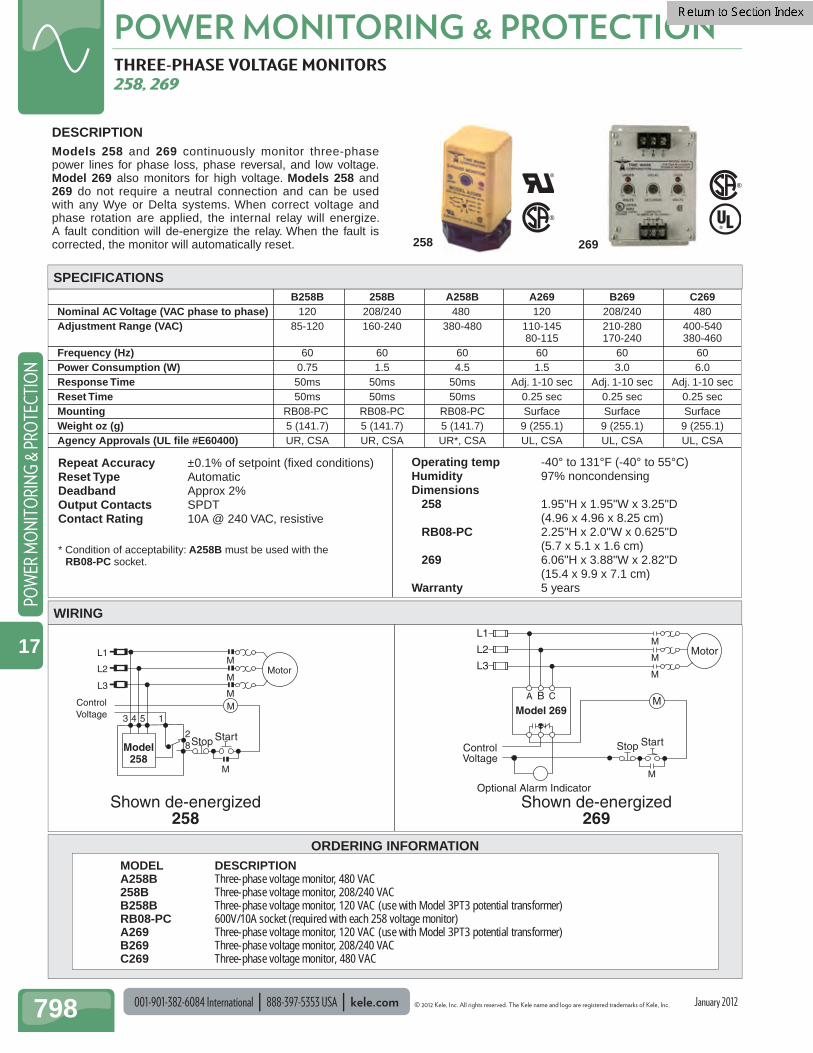
001-901-382-6084 International 888-397-5353 USA kele.com © 2012 Kele, Inc. All rights reserved. The Kele name and logo are registered trademarks of Kele, Inc.
POWER MONITORING & PROTECTION
798
POW
ER M
ON
ITO
RIN
G &
PRO
TECT
ION
17
B258B 258B A258B A269 B269 C269Nominal AC Voltage (VAC phase to phase) 120 208/240 480 120 208/240 480Adjustment Range (VAC) 85-120 160-240 380-480 110-145 210-280 400-540 80-115 170-240 380-460Frequency (Hz) 60 60 60 60 60 60Power Consumption (W) 0.75 1.5 4.5 1.5 3.0 6.0Response Time 50ms 50ms 50ms Adj. 1-10 sec Adj. 1-10 sec Adj. 1-10 secReset Time 50ms 50ms 50ms 0.25 sec 0.25 sec 0.25 secMounting RB08-PC RB08-PC RB08-PC Surface Surface SurfaceWeight oz (g) 5 (141.7) 5 (141.7) 5 (141.7) 9 (255.1) 9 (255.1) 9 (255.1)Agency Approvals (UL file #E60400) UR, CSA UR, CSA UR*, CSA UL, CSA UL, CSA UL, CSA
Repeat Accuracy ±0.1% of setpoint (fixed conditions)Reset Type AutomaticDeadband Approx 2%Output Contacts SPDTContact Rating 10A @ 240 VAC, resistive
* Condition of acceptability: A258B must be used with the RB08-PC socket.
Operating temp -40° to 131°F (-40° to 55°C)Humidity 97% noncondensingDimensions 258 1.95"H x 1.95"W x 3.25"D (4.96 x 4.96 x 8.25 cm) RB08-PC 2.25"H x 2.0"W x 0.625"D (5.7 x 5.1 x 1.6 cm) 269 6.06"H x 3.88"W x 2.82"D (15.4 x 9.9 x 7.1 cm)Warranty 5 years
ORDERING INFORMATION
THREE-PHASE VOLTAGE MONITORS 258, 269
DESCRIPTIONModels 258 and 269 continuously monitor three-phase power lines for phase loss, phase reversal, and low voltage.Model 269 also monitors for high voltage. Models 258 and 269 do not require a neutral connection and can be used with any Wye or Delta systems. When correct voltage and phase rotation are applied, the internal relay will energize. A fault condition will de-energize the relay. When the fault is corrected, the monitor will automatically reset.
L3
L2
L1
ControlVoltage
Optional Alarm Indicator
M
M
M
M
StartStop
Model 269
Motor
CBA MM
M
1
28
543
L3
ControlVoltage
Motor
StopModel258
Start
L2
L1
M
M
M
Shown de-energized258
Shown de-energized269
WIRING
MODEL DESCRIPTION A258B Three-phase voltage monitor, 480 VAC 258B Three-phase voltage monitor, 208/240 VAC B258B Three-phase voltage monitor, 120 VAC (use with Model 3PT3 potential transformer) RB08-PC 600V/10A socket (required with each 258 voltage monitor) A269 Three-phase voltage monitor, 120 VAC (use with Model 3PT3 potential transformer) B269 Three-phase voltage monitor, 208/240 VAC C269 Three-phase voltage monitor, 480 VAC
SPECIFICATIONS
258 269
January 2012

© 2012 Kele, Inc. All rights reserved. The Kele name and logo are registered trademarks of Kele, Inc. kele.com 888-397-5353 USA 001-901-382-6084 International 799
POWER MONITORING & PROTECTIONPO
WER M
ON
ITORIN
G & PRO
TECTION
17
January 2012
ORDERING INFORMATION
MOTORSAVER™ THREE-PHASE VOLTAGE MONITOR 201A
Supply Watts 5W Frequency 50* or 60 Hz Transient Protection 2500V for 10 ms Line Voltage Monitored Three-phase, 190-480
VAC, adjustable Low Voltage Trip 90% of setpoint Low Voltage Reset 93% of setpoint Reset Delay Time after Fault 2 seconds Reset Delay Time after Power Loss
2 seconds Trip Delay Time Low Voltage 4 seconds Trip Delay Time Phase Fault 2 seconds Trip Delay Time Unbalance 2 seconds Voltage Unbalance Reset 4.5% Voltage Unbalance Trip 6% Dimensions 2.37"W x 1.75"H x 4.25"L
(6.0 x 4.4 x 10.8cm) Weight 0.56 lb (0.25 kg) Approvals UL Listed, File #E68520,
CE certifi ed Warranty 5 years
DESCRIPTION The MotorSaver™ 201A Three-Phase Voltage Monitor is an autoranging plug-in voltage monitor designed to protect three-phase motors regardless of size. It is used on 190-480 VAC 50/60 Hz motors to prevent damage caused by single phasing, low voltage, phase reversal, or voltage unbalance. To detect harmful power line conditions, the unique microprocessor-based voltage and phase sensing circuit constantly monitors the three-phase voltages. When a harmful condition is detected, the Model 201A MotorSaver's output relay is deactivated after a fi xed trip-delay time period. The output relay reactivates after power line conditions return to an acceptable level for a fi xed restart delay time. The trip delay prevents nuisance tripping due to rapidly fl uctuating power line conditions.
FEATURES
• Protection of three-phase motors against single phasing, low voltage, phase reversal, and voltage unbalance
• DIN rail- or surface-mounted socket • UL and ULC listed, CE certifi ed• Bicolor LED indication of normal and fault conditions• Single-phase condition detection regardless of
regenerated voltages
OL
OLOLOL
Motor
L1
L1L2L3
L2 L3
M
Start
M
MMM
StopHand
Auto Pilot
OffControlVoltage
240 VAC max
201A2 81
43 5
WIRING
MODEL DESCRIPTION 201A MotorSaver three-phase voltage monitor OT08PC Socket, 600 VAC, DIN rail or surface mount
SPECIFICATIONS
201A
Shown de-energizedModel 201A
OT08PC
* 50 Hz will increase all delay times by 20%.
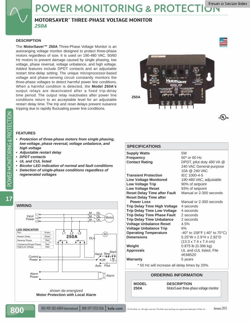
001-901-382-6084 International 888-397-5353 USA kele.com © 2012 Kele, Inc. All rights reserved. The Kele name and logo are registered trademarks of Kele, Inc.
POWER MONITORING & PROTECTION
800
POW
ER M
ON
ITO
RIN
G &
PRO
TECT
ION
17
January 2012
ORDERING INFORMATION
MOTORSAVER™ THREE-PHASE VOLTAGE MONITOR 250A
Supply Watts 5W Frequency 50* or 60 Hz Contact Rating DPDT, pilot duty 480 VA @
240 VAC General-purpose 10A @ 240 VAC
Transient Protection IEC 1000-4-5 Line Voltage Monitored 190-480 VAC, adjustable Low Voltage Trip 90% of setpoint Low Voltage Reset 93% of setpoint Reset Delay Time after Fault Manual or 2-300 seconds Reset Delay Time after Power Loss Manual or 2-300 seconds Trip Delay Time High Voltage 4 seconds Trip Delay Time Low Voltage 4 seconds Trip Delay Time Phase Fault 2 seconds Trip Delay Time Unbalance 2 seconds Voltage Unbalance Reset 4.5% Voltage Unbalance Trip 6% Operating Temperature -40° to 158°F (-40° to 70°C) Dimensions 5.25"W x 2.9"H x 2.92"D
(13.3 x 7.4 x 7.4 cm) Weight 0.875 lb (0.396 kg) Approvals UL and cUL listed, File
#E68520 Warranty 5 years
DESCRIPTION
The MotorSaver™ 250A Three-Phase Voltage Monitor is an autoranging voltage monitor designed to protect three-phase motors regardless of size. It is used on 190-480 VAC, 50/60 Hz motors to prevent damage caused by single phasing, low voltage, phase reversal, voltage unbalance, and high voltage. Added features include DPDT contacts and an adjustable restart time-delay setting. The unique microprocessor-based voltage and phase-sensing circuit constantly monitors the three-phase voltages to detect harmful power line conditions. When a harmful condition is detected, the Model 250A's output relays are deactivated after a fixed trip-delay time period. The output relay reactivates after power line conditions return to an acceptable level for an adjustable restart delay time. The trip and reset delays prevent nuisance tripping due to rapidly fl uctuating power line conditions.
FEATURES
• Protection of three-phase motors from single phasing, low-voltage, phase reversal, voltage unbalance, and high voltage
• Adjustable restart delay• DPDT contacts• UL and CUL listed• Bicolor LED indication of normal and fault conditions• Detection of single-phase conditions regardless of
regenerated voltages
OL
OLOLOL
Motor
L1
L1L2L3
L2 L3 M
Start
M
MMM
StopHand
Auto Pilot
Off
InputPower
ControlPower
AlarmPower Alarm
250A
WIRING
MODEL DESCRIPTION 250A MotorSaver three-phase voltage monitor
SPECIFICATIONS
Run Green
Restart Delay Green
Reverse Phase Red
Unbalance/Single Phase RedHigh/Low Voltage Red
LED INDICATOR
250A
shown de-energizedMotor Protection with Local Alarm
* 50 Hz will increase all delay times by 20%.

© 2012 Kele, Inc. All rights reserved. The Kele name and logo are registered trademarks of Kele, Inc. kele.com 888-397-5353 USA 001-901-382-6084 International 801
POWER MONITORING & PROTECTIONPO
WER M
ON
ITORIN
G & PRO
TECTION
17
January 2012
ORDERING INFORMATION
MOTORSAVER™ THREE-PHASE VOLTAGE MONITOR 355 SERIES
Supply Watts 6W maximum Frequency 50*/60 Hz Contact Rating SPDT, pilot duty 470 VA @ 600
VAC (400 or 600V range) General-purpose 10A @ 240 VAC (200V range)
Transient Protection 2500V for 10 ms Line Voltage Monitored 190-240, 380-480, or 575-600 VAC Low Voltage Trip 90% of setpoint (±1%) Low Voltage Reset 93% of setpoint (±1%) Reset Delay Time after Fault
Manual or 2-300 seconds Reset Delay Time after Power Loss
Manual or 2-300 seconds Trip Delay Time High Voltage
2-30 seconds, adjustable
Trip Delay Time Low Voltage 2-30 seconds, adjustable
Trip Delay Time Phase Fault 0.5 seconds
Trip Delay Time Unbalance 2-30 seconds, adjustable
Voltage Unbalance Reset Trip setting minus 1%
Voltage Unbalance Trip 2% to 8%, adjustable Dimensions 2.9"H x 5.25"W x 2.9"D
(7.4 x 13.3 x 7.4 cm) Weight 1.0 lb (0.45 kg) Approvals UL and cUL listed, File #E68520 Warranty 5 years
DESCRIPTION
MotorSaver™ 355 Series Three-Phase Voltage Monitors are designed to protect three-phase motors regardless of size. The 355-200 model monitors 190-240 VAC input voltages, the 355-400 model monitors 380-480 VAC input voltages, and the 355-600 model monitors 575-600 VAC input voltages. The unique microprocessor-based voltage and phase-sensing circuit constantly monitors the three-phase voltages to detect harmful power line conditions, including single phasing, low-voltage, phase reversal, voltage unbalance, and high voltage. When a harmful condition is detected, the 355 Series output relays are deactivated after an adjustable trip-delay time period. The output relay reactivates after power line conditions return to an acceptable level for an adjustable restart delay time. The trip and reset delays prevent nuisance tripping due to rapidly fl uctuating power line conditions.
FEATURES
• Protection of three-phase motors from loss of any phase, low-voltage, phase reversal, voltage unbalance, and high voltage
• Adjustable restart delay• Adjustable trip delay• Adjustable voltage-unbalance trip point• Four diagnostic LEDs show overvoltage, undervoltage,
voltage unbalance, reverse-phase and normal conditions
• UL and ULC listed• Single-phase condition detection regardless of
regenerated voltages
OL
OLOLOL
Motor
L1
L1L2L3
L2 L3 M
Start
M
MMM
StopHand
Auto Pilot
OffControlVoltage
355 Series
WIRING
MODEL DESCRIPTION 355-200 Three-phase voltage monitor, 190-240 VAC 355-400 Three-phase voltage monitor, 380-480 VAC 355-600 Three-phase voltage monitor, 575-600 VAC
SPECIFICATIONS
355-400
Shown de-energized
* 50 Hz will increase all delay times by 20%.
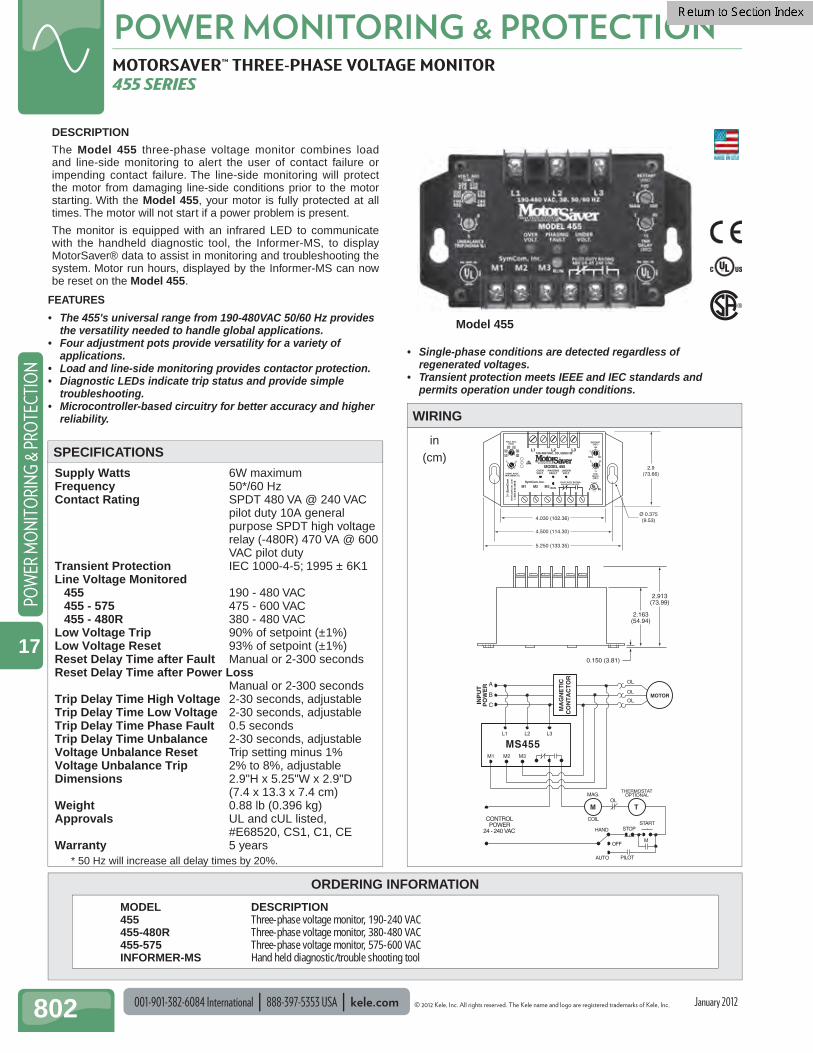
001-901-382-6084 International 888-397-5353 USA kele.com © 2012 Kele, Inc. All rights reserved. The Kele name and logo are registered trademarks of Kele, Inc.
POWER MONITORING & PROTECTION
802
POW
ER M
ON
ITO
RIN
G &
PRO
TECT
ION
17
January 2012
ORDERING INFORMATION
MOTORSAVER™ THREE-PHASE VOLTAGE MONITOR 455 SERIES
Supply Watts 6W maximum Frequency 50*/60 Hz Contact Rating SPDT 480 VA @ 240 VAC
pilot duty 10A general purpose SPDT high voltage relay (-480R) 470 VA @ 600 VAC pilot duty
Transient Protection IEC 1000-4-5; 1995 ± 6K1 Line Voltage Monitored 455 190 - 480 VAC 455 - 575 475 - 600 VAC 455 - 480R 380 - 480 VAC Low Voltage Trip 90% of setpoint (±1%) Low Voltage Reset 93% of setpoint (±1%) Reset Delay Time after Fault Manual or 2-300 seconds Reset Delay Time after Power Loss
Manual or 2-300 seconds Trip Delay Time High Voltage 2-30 seconds, adjustable Trip Delay Time Low Voltage 2-30 seconds, adjustable Trip Delay Time Phase Fault 0.5 seconds Trip Delay Time Unbalance 2-30 seconds, adjustable Voltage Unbalance Reset Trip setting minus 1% Voltage Unbalance Trip 2% to 8%, adjustable Dimensions 2.9"H x 5.25"W x 2.9"D
(7.4 x 13.3 x 7.4 cm) Weight 0.88 lb (0.396 kg) Approvals UL and cUL listed,
#E68520, CS1, C1 , CEWarranty 5 years
DESCRIPTION
The Model 455 three-phase voltage monitor combines load and line-side monitoring to alert the user of contact failure or impending contact failure. The line-side monitoring will protect the motor from damaging line-side conditions prior to the motor starting. With the Model 455, your motor is fully protected at all times. The motor will not start if a power problem is present.
The monitor is equipped with an infrared LED to communicate with the handheld diagnostic tool, the Informer-MS, to display MotorSaver® data to assist in monitoring and troubleshooting the system. Motor run hours, displayed by the Informer-MS can now be reset on the Model 455.
INP
UT
PO
WE
R
L1
M1 M2 M3
L2 L3
OL
OL
OLB
A
C
MA
GN
ET
ICC
ON
TA
CT
OR
MOTOR
MS455
THERMOSTATOPTIONAL
CONTROLPOWER
24 - 240 VAC
TM
M
MAG.
COIL
HAND STOP
OFF
AUTO PILOT
START
OL
WIRING
MODEL DESCRIPTION 455 Three-phase voltage monitor, 190-240 VAC 455-480R Three-phase voltage monitor, 380-480 VAC 455-575 Three-phase voltage monitor, 575-600 VAC INFORMER-MS Hand held diagnostic/trouble shooting tool
SPECIFICATIONS
FEATURES
• The 455's universal range from 190-480VAC 50/60 Hz provides the versatility needed to handle global applications.
• Four adjustment pots provide versatility for a variety of applications.
• Load and line-side monitoring provides contactor protection.• Diagnostic LEDs indicate trip status and provide simple
troubleshooting.• Microcontroller-based circuitry for better accuracy and higher
reliability.
L1 L2 L3190-480 VAC, 3Ø, 50/60 HZ
MODEL 455OVERVOLT.
PHASINGFAULT
UNDERVOLT.
PILOT DUTY RATING480 VA AT 240 VAC
RUN
VOLT. ADJ.(VAC)
208416
220440
200400
230460
190380
240480
UNBALANCETRIP (NEMA %)
82
M1 M2 M3SymCom. Inc.
300
100
2
MAN
RESTART(SEC)
302
15TRIP
DELAY(SEC)
IRIRLINKLINK
IND. CONT. EQ.
LISTED
784X
4.030 (102.36)
5.250 (133.35)
4.500 (114.30)
Ø 0.375(9.53)
2.9(73.66)
0.150 (3.81)
2.163(54.94)
2.913(73.99)
Model 455
* 50 Hz will increase all delay times by 20%.
• Single-phase conditions are detected regardless of regenerated voltages.
• Transient protection meets IEEE and IEC standards and permits operation under tough conditions.
in(cm)
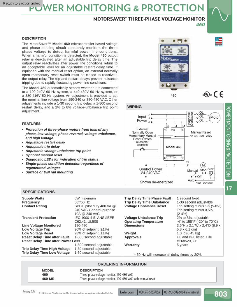
© 2012 Kele, Inc. All rights reserved. The Kele name and logo are registered trademarks of Kele, Inc. kele.com 888-397-5353 USA 001-901-382-6084 International 803
POWER MONITORING & PROTECTIONPO
WER M
ON
ITORIN
G & PRO
TECTION
17
January 2012
ORDERING INFORMATION
MOTORSAVER™ THREE-PHASE VOLTAGE MONITOR 460
Supply Watts 6W maximum Frequency 50*/60 Hz Contact Rating SPDT, pilot duty 480 VA @
240 VAC General-purpose 10A @ 240 VAC
Transient Protection IEC 1000-4-5, ANSI/IEEE C62.41, UL508
Line Voltage Monitored 190-480 Low Voltage Trip 90% of setpoint (±1%) Low Voltage Reset 93% of setpoint (±1%) Reset Delay Time after Fault 1-500 second adjustable Reset Delay Time after Power Loss
1-500 second adjustable Trip Delay Time High Voltage 1-30 second adjustable Trip Delay Time Low Voltage 1-30 second adjustable
Trip Delay Time Phase Fault 1 second fi xed Trip Delay Time Unbalance 1-30 second adjustable Voltage Unbalance Reset Trip setting minus 1% (5-8%)
Trip setting minus 0.5% (2-4%)
Voltage Unbalance Trip 2% to 8%, adjustable Operating Temperature -4° to 158°F (-20° to 70°C) Dimensions 3.5"H x 2.1"W x 2.4"D (8.9 x
5.3 x 6.1 cm) Weight 1.0 lb (0.45 kg) Approvals UL and cUL listed, File
#E68520, CE Warranty 5 years
DESCRIPTION
The MotorSaver™ Model 460 microcontroller-based voltage and phase sensing circuit constantly monitors the three phase voltage to detect harmful power line conditions. When a harmful condition is detected, the Model 460 output relay is deactivated after an adjustable trip delay time. The output relay reactivates after power line conditions return to an acceptable level for an adjustable restart delay time. If equipped with the manual reset option, an external normally open momentary reset switch must be closed to reactivate the output relay. The trip and restart delays prevent nuisance tripping due to rapidly fl uctuating power line conditions.
The Model 460 automatically senses whether it is connected to a 190-240V 60 Hz system, a 440-480V 60 Hz system, or a 380-416V 50 Hz system. An adjustment is provided to set the nominal line voltage from 190-240 or 380-480 VAC. Other adjustments include a 1-30 second trip delay, a 1-500 second restart delay, and a 2% to 8% voltage-unbalance trip point adjustment.
FEATURES
• Protection of three-phase motors from loss of any phase, low-voltage, phase reversal, voltage unbalance, and high voltage
• Adjustable restart delay• Adjustable trip delay• Adjustable voltage unbalance trip point• Optional manual reset• Diagnostic LEDs for indication of trip status• Single-phase condition detection regardless of
regenerated voltages• Surface or DIN rail mounting
Control Power24-240 VAC
ExternalNormally Open
Momentary ManualReset Switch
(customersupplied)
Shown de-energized
Model 460
InputPower
Motor
OL
OLOLOL
L1
L1
L2
L3
L2 L3
4 5 6
1 2 3
AutoPilot Contact
Manual Reseton 460-MR only
Off
Manual Stop Start
M
M
Mag
netic
Con
tact
or
WIRING
MODEL DESCRIPTION 460 Three-phase voltage monitor, 190-480 VAC 460-MR Three-phase voltage monitor, 190-480 VAC with manual reset
SPECIFICATIONS
460
* 50 Hz will increase all delay times by 20%.
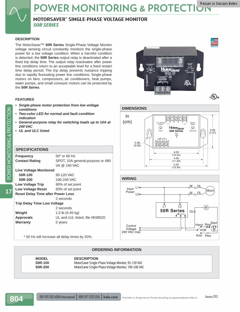
001-901-382-6084 International 888-397-5353 USA kele.com © 2012 Kele, Inc. All rights reserved. The Kele name and logo are registered trademarks of Kele, Inc.
POWER MONITORING & PROTECTION
804
POW
ER M
ON
ITO
RIN
G &
PRO
TECT
ION
17
January 2012
ORDERING INFORMATION
MOTORSAVER™ SINGLE-PHASE VOLTAGE MONITOR 50R SERIES
Frequency 50* or 60 Hz Contact Rating SPDT, 10A general-purpose or 480
VA @ 240 VAC Line Voltage Monitored 50R-100 95-120 VAC 50R-200 190-240 VAC Low Voltage Trip 90% of set point Low Voltage Reset 93% of set point Reset Delay Time after Power Loss
2 seconds Trip Delay Time Low Voltage
2 seconds Weight 1.0 lb (0.45 kg) Approvals UL and cUL listed, fi le #E68520 Warranty 5 years
(VAC) (Seconds)
L1 L2
RunLight
50R Series
Line VoltageAdjust
RestartDelay
4.03(10.24)
4.50(11.43)
5.25(13.34)
2.90(7.37)
0.38(0.95)
in(cm)
DESCRIPTION
The MotorSaver™ 50R Series Single-Phase Voltage Monitor voltage sensing circuit constantly monitors the single-phase power for a low voltage condition. When a harmful condition is detected, the 50R Series output relay is deactivated after a fi xed trip delay time. The output relay reactivates after power line conditions return to an acceptable level for a fi xed restart time delay period. The trip delay prevents nuisance tripping due to rapidly fl uctuating power line conditions. Single-phase motors on fans, compressors, air conditioners, heat pumps, water pumps, and small conveyor motors can be protected by the 50R Series.
FEATURES
• Single-phase motor protection from low voltage conditions
• Two-color LED for normal and fault condition indication
• General-purpose relay for switching loads up to 10A at 240 VAC
• UL and ULC listed
OL
OL
OLMotor
L1
L1
L2
L2 M
Start
M
M
M
StopHand
Auto Pilot
OffControlVoltage
240 VAC max
InputPower
50R Series
WIRING
MODEL DESCRIPTION 50R-100 MotorSaver Single-Phase Voltage Monitor, 95-120 VAC 50R-200 MotorSaver Single-Phase Voltage Monitor, 190-240 VAC
DIMENSIONS
SPECIFICATIONS
* 50 Hz will increase all delay times by 20%.
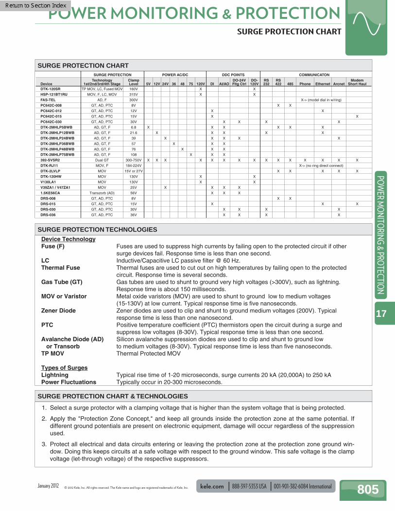
© 2012 Kele, Inc. All rights reserved. The Kele name and logo are registered trademarks of Kele, Inc. kele.com 888-397-5353 USA 001-901-382-6084 International 805
POWER MONITORING & PROTECTIONPO
WER M
ON
ITORIN
G & PRO
TECTION
17
January 2012
SURGE PROTECTION CHART
SURGE PROTECTION TECHNOLOGIES
SURGE PROTECTION CHART
SURGE PROTECTION CHART & TECHNOLOGIES
NOTACINUMMOCSTNIOP CDDCD/CA REWOPNOITCETORP EGRUS
DeviceTechnology
1st/2nd/3rd/4th StageClampLevel 5V 12V 24V 36 48 75 120V DI AI/AO
DO-24VFltg Ctrl
DO-120V
RS232
RS422 485 Phone Ethernet Arcnet
ModemShort Haul
DTK-120SR XXV061
HSP-121BT1RU XXV513VOM ,CL ,F ,VOM
FAS-TEL AD, F 300V X-> (model dial in w/ring)
PC642C-008 GT, AD, PTC 8V X X
PC642C-012 XXV21CTP ,DA ,TG
PC642C-015 XV51CTP ,DA ,TG X
PC642C-030 XXXXV03CTP ,DA ,TG
DTK-2MHLP5BWB XXXXXX8.6
DTK-2MHLP12BWB XXXXX6.12
DTK-2MHLP24BWB XXXXX93
DTK-2MHLP36BWB XXX75
DTK-2MHLP48BWB XXX67
DTK-2MHLP75BWB XXX801
392-SVSR2 Dual GT 300-750V X X X X X X X X X X X X X X X
DTK-RJ11 MOV, F 184-224V X-> (no ring direct connect)
DTK-2LVLP MOV 15V or 27V X X X X X
DTK-120HW XXV031VOM
V130LA1 XXV031VOM
V39ZA1 / V47ZA1 XXXXV52VOM
1.5KE56CA XXXV65)DA( brozsnarT
DRS-008 GT, AD, PTC 8V X X
DRS-015 XXXV51CTP ,DA ,TG
DRS-030 XXXXV03CTP ,DA ,TG
DRS-036 XXXXV63CTP ,DA ,TG
AD, GT, F
AD, GT, F
AD, GT, F
AD, GT, F
AD, GT, F
AD, GT, F
TP MOV, LC, Fused MOV
Device TechnologyFuse (F) Fuses are used to suppress high currents by failing open to the protected circuit if other
surge devices fail. Response time is less than one second.LC Inductive/Capacitive LC passive filter @ 60 Hz.Thermal Fuse Thermal fuses are used to cut out on high temperatures by failing open to the protected
circuit. Response time is several seconds. Gas Tube (GT) Gas tubes are used to shunt to ground very high voltages (>300V), such as lightning.
Response time is about 150 milliseconds.MOV or Varistor Metal oxide varistors (MOV) are used to shunt to ground low to medium voltages
(15-130V) at low current. Typical response time is five nanoseconds.Zener Diode Zener diodes are used to clip and shunt to ground medium voltages (200V). Typical
response time is less than one nanosecond. PTC Positive temperature coefficient (PTC) thermistors open the circuit during a surge and
suppress low voltages (8-30V). Typical response time is less than one second.Avalanche Diode (AD) Silicon avalanche suppression diodes are used to clip and shunt to ground low or TransorbTP MOV
to medium voltages (8-30V). Typical response time is less than five nanoseconds.Thermal Protected MOV
Types of SurgesLightning Typical rise time of 1-20 microseconds, surge currents 20 kA (20,000A) to 250 kAPower Fluctuations Typically occur in 20-300 microseconds.
1. Select a surge protector with a clamping voltage that is higher than the system voltage that is being protected.
2. Apply the "Protection Zone Concept," and keep all grounds inside the protection zone at the same potential. Ifdifferent ground potentials are present on electronic equipment, damage will occur regardless of the suppressionused.
3. Protect all electrical and data circuits entering or leaving the protection zone at the protection zone ground win-dow. Doing this keeps circuits at a safe voltage with respect to the ground window. This safe voltage is the clampvoltage (let-through voltage) of the respective suppressors.
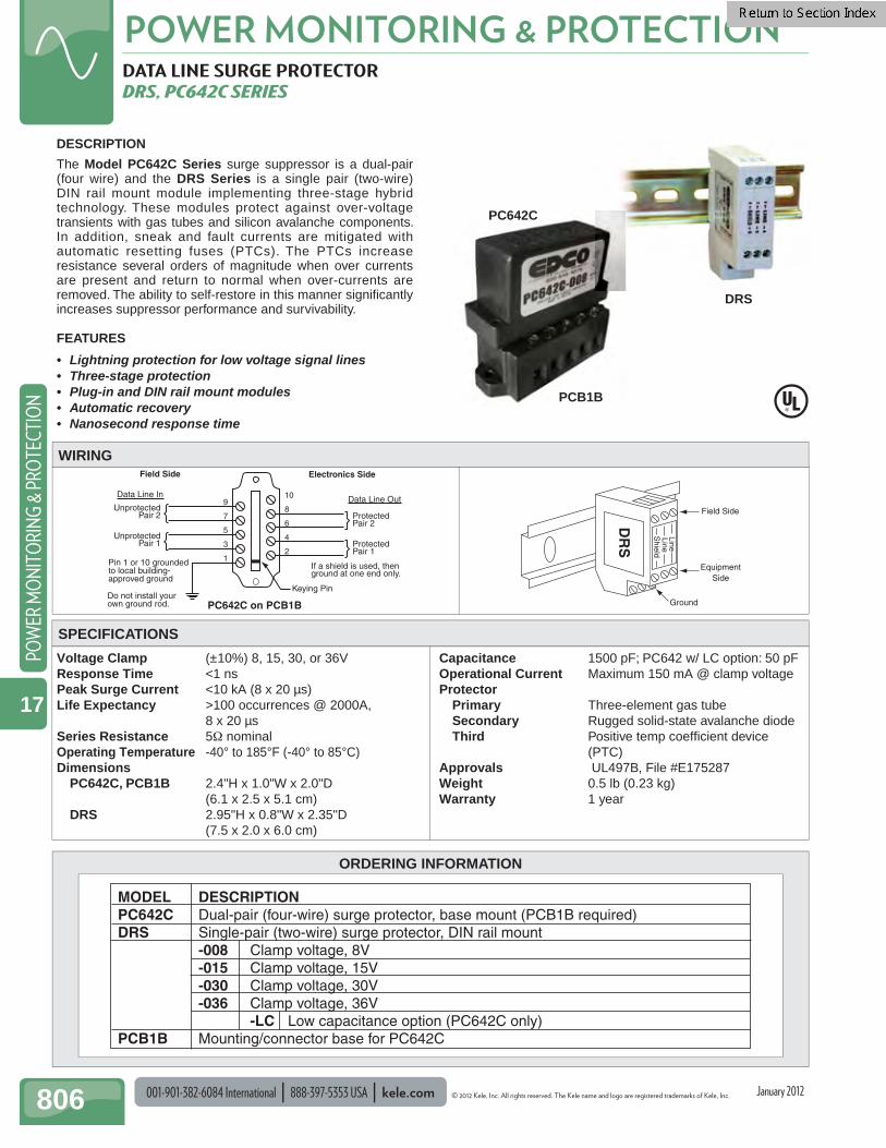
001-901-382-6084 International 888-397-5353 USA kele.com © 2012 Kele, Inc. All rights reserved. The Kele name and logo are registered trademarks of Kele, Inc.
POWER MONITORING & PROTECTION
806
POW
ER M
ON
ITO
RIN
G &
PRO
TECT
ION
17
January 2012
ORDERING INFORMATION
MODEL DESCRIPTIONPC642C Dual-pair (four-wire) surge protector, base mount (PCB1B required)DRS Single-pair (two-wire) surge protector, DIN rail mount -008 Clamp voltage, 8V -015 Clamp voltage, 15V -030 Clamp voltage, 30V -036 Clamp voltage, 36V -LC Low capacitance option (PC642C only)PCB1B Mounting/connector base for PC642C
DATA LINE SURGE PROTECTOR DRS, PC642C SERIES
Voltage Clamp (±10%) 8, 15, 30, or 36VResponse Time <1 nsPeak Surge Current <10 kA (8 x 20 µs)Life Expectancy >100 occurrences @ 2000A, 8 x 20 µsSeries Resistance 5Ω nominalOperating Temperature -40° to 185°F (-40° to 85°C)Dimensions PC642C, PCB1B 2.4"H x 1.0"W x 2.0"D (6.1 x 2.5 x 5.1 cm) DRS 2.95"H x 0.8"W x 2.35"D (7.5 x 2.0 x 6.0 cm)
Capacitance 1500 pF; PC642 w/ LC option: 50 pFOperational Current Maximum 150 mA @ clamp voltageProtector
Primary Three-element gas tubeSecondary Rugged solid-state avalanche diodeThird Positive temp coeffi cient device
(PTC)Approvals UL497B, File #E175287Weight 0.5 lb (0.23 kg)Warranty 1 year
DESCRIPTION
The Model PC642C Series surge suppressor is a dual-pair (four wire) and the DRS Series is a single pair (two-wire) DIN rail mount module implementing three-stage hybrid technology. These modules protect against over-voltage transients with gas tubes and silicon avalanche components. In addition, sneak and fault currents are mitigated with automatic resetting fuses (PTCs). The PTCs increase resistance several orders of magnitude when over currents are present and return to normal when over-currents are removed. The ability to self-restore in this manner signifi cantly increases suppressor performance and survivability.
FEATURES
• Lightning protection for low voltage signal lines• Three-stage protection• Plug-in and DIN rail mount modules• Automatic recovery• Nanosecond response time
Ground
EquipmentSide
Field Side
DR
S
Shield
LineLine
WIRING
SPECIFICATIONS
If a shield is used, then ground at one end only.
Keying Pin
PC642C on PCB1B
10
8
6
4
2
9
7
5
3
1Pin 1 or 10 grounded to local building- approved ground
Do not install your own ground rod.
UnprotectedPair 1
UnprotectedPair 2
ProtectedPair 1
ProtectedPair 2
Data Line InData Line Out
Field Side Electronics Side
DRS
PC642C
PCB1B

© 2012 Kele, Inc. All rights reserved. The Kele name and logo are registered trademarks of Kele, Inc. kele.com 888-397-5353 USA 001-901-382-6084 International 807
POWER MONITORING & PROTECTIONPO
WER M
ON
ITORIN
G & PRO
TECTION
17
January 2012
ORDERING INFORMATION
SURGE PROTECTORS DTK SERIES
DTK-120HW AC Hard-Wired Surge Protection Service Voltage 110/125 VAC Frequency 50/60 Hz Filtering RFI/EMI noise Continuous Current Unlimited Protection L-N, L-G, N-G Energy Dissipation 255 Joules Clamping Level 130 VRMS/185V peak Surge Current 19,500A Response Time <5 ns Connections 3/4" hub-mount 3-12 AWG leads Dimensions 2.9"H x 2.8"W x 1.6"D
(7.3 x 7.1 x 4.0 cm) Weight 0.5 lb (0.22 kg) Approvals UL 1449 3rd Edition, cUL 1449, IEEE
C62.41B, File #E136659 Warranty 10 years
DESCRIPTION
The DTK Series products are general-purpose MOV based power line, telephone line, and data line surge protectors. They are designed to protect electronic equipment from surges and spikes that may be present on power inputs, communications, or data lines.
FEATURES
• Metal-Oxide Varistor (MOV) technology• Self-restoring after each surge within ratings• Nanosecond response time• UL listed
DTK-2LVLP
DTK-120HW
ProtectedEquipment
ProtectedLine 120 VACGround
ProtectedEquipment
To Building Ground
To Building GroundIf a shield is used, then ground at one end only.
DataLine In
DTK-RJ11
Wall Jack
Neutral(white) (green)(black)
Hot
UnprotectedPair #1
UnprotectedPair #2
ProtectedPair #1
ProtectedPair #2
WIRING
SPECIFICATIONS
DTK-RJ11
MODEL DESCRIPTION DTK-120HW 120V inline surge protector DTK-RJ11 130V telephone line surge protector DTK-2LVLPX 15V four-wire data line surge protector DTK-2LVLPLV 27V four-wire data line surge protector
DTK-120HW DTK-2LVLP
Note: Other models and voltage levels available on a special order basis. Contact Kele for more details.
DTK-RJ11 Data/Phone Line Protection Service Voltage 130 VRMS Let Through Voltage 184-224V Continuous Current 150 mA Protection RJ11/RJ14/RJ45 female to ground Energy Dissipation 76 joules Surge Current 9000 amps/pair Response Time <5 ns Connections RJ11/RJ14/RJ45 female in/out +
ground wire Operating Temperature -40° to 158°F (-40° to 70°C) Operating Humidity Maximum 95% (non-condensing) Dimensions 1.7"H x 3.0"W x 1.2"D
(6.9 x 7.8 x 2.9 cm) Weight 0.25 lb (0.11 kg) Approvals UL 497A, File #E163310 Warranty 1 year
DTK-2LVLP Low-Voltage Data Line Protection Let Through Voltage X: 15 VRMS, LV: 27 VRMS Continuous Current Unlimited Accuracy X: 15 VRMS, LV: 27 VRMS Protection L-G (all lines protected) Energy Dissipation X: 8 joules/pair LV: 17 joules/pair Surge Current 2000 amps/pair Response Time <5 ns Connections Screw terminals 22-16 AWG wire Dimensions 1.6"H x 3.0"W x 1.6"D
(4.1 x 7.6 x 4.1 cm) Weight 0.25 lb (0.11 kg) Approvals UL 497B, File #E163310 Warranty 1 year

001-901-382-6084 International 888-397-5353 USA kele.com © 2012 Kele, Inc. All rights reserved. The Kele name and logo are registered trademarks of Kele, Inc.
POWER MONITORING & PROTECTION
808
POW
ER M
ON
ITO
RIN
G &
PRO
TECT
ION
17
January 2012
DTK-120SRService Voltage 120VMCOV 150VSuppressed VoltageRating 600VContinuous Current 20AEMI/RFI Attenuation Up to 35dB, 100kHz-100MHzSurge Current 54,000 ampsProtection L-N, L-G, N-GOperating Temperature 32° to 104°F (0° to 40°C)Dimensions 6.87"W x 3.50"H x 2.50"D (17.45 x 9.06 x 6.35 cm)Weight 0.76 lb (0.45 kg)Approvals UL1449, 3rd EditionWarranty 10-year limited
DTK-2MHLPWBService voltage 5B 0-5 VDC 36B 36 VDC 12B 12 VDC 48B 48 VDC 24B 24 VDC 75B 75 VDCMCOV/Let-Through Voltage 5B 5/6.8 VDC 36B 48/57 VDC 12B 18/21.6 VDC 48B 64/76 VDC 24B 33/39 VDC 75B 90/108 VDCContinuous Current 5ASurge Current 20kAData Rate 200kbps (5V) to 2Mbps (130V)Protection L-G (all lines protected)Connections Edge card into DTK-MB mounting
baseOperating Temperature -40° to 158°F (-40° to 70°C)Dimensions 4.5"W x 1.75"H x 3.0"D (11.5 x 4.5 x 7.6 cm)Weight 0.078 lb (0.036 kg) - with baseApprovals UL 497B, DTK-120SR Recognition,
File # E328921, DTK-2MHLP UL File #E14557
Warranty 10-year limited
DESCRIPTION The new Model DTK-120SR is an in-line, four-stage, power-line surge protector with EMI/RFI fi ltering. It is designed for mounting in an enclosure or control panel. Series installation eliminates the need to dedicate a circuit breaker for surge protection while allowing for installation fl exibility. The 120SR meets stringent government and military specs for fi re panel applications and is suitable for use on critical 20 Amp loads.
The Model DTK-2MHLP series of signal, data and loop circuit surge protectors provide robust protection in a compact package. Designed for ease of installation with convenient fi eld-replaceable modules. The 2MHLP protects two circuit pairs per module. Applications include protection of 4-20mA current loops, alarm pane NAC, SLC and IDC loops, and burglar alarm panels.
FEATURES
DTK-120SR• Series design for fast response and best protection• Four-stage hybrid circuit design• User replaceable fusing• EMI/RFI fi ltering• Compact design• Screw terminals w/safety cover• LED's for protection status, ground presence, ground
fault indication and fuse status
SPECIFICATIONS
DTK-120SR
DTK-2MHLPWB• Multi-stage, SAD technology, hybrid design• Hard-wire mounting base• Field replaceable, hot swappable, modular edge card
connection design• Multiple voltage levels for variety of voice/data
applications• Two pairs protected per module, can be extended to ten
pairs using a common ground using DTK-MB base
DTK-2MHLP
POWER/DATA SURGE PROTECTOR DTK-120SR, DTK-2MHLP
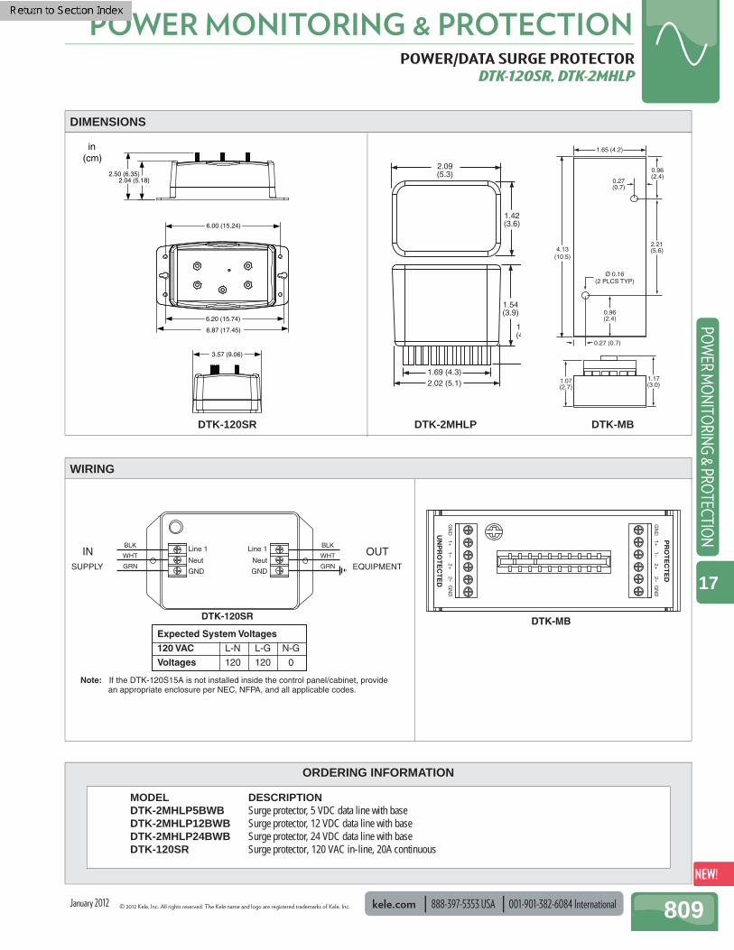
© 2012 Kele, Inc. All rights reserved. The Kele name and logo are registered trademarks of Kele, Inc. kele.com 888-397-5353 USA 001-901-382-6084 International 809
POWER MONITORING & PROTECTIONPO
WER M
ON
ITORIN
G & PRO
TECTION
17
January 2012
in(cm)
2.50 (6.35)2.04 (5.18)
6.00 (15.24)
6.20 (15.74)
6.87 (17.45)
3.57 (9.06)
DIMENSIONS
ORDERING INFORMATION
POWER/DATA SURGE PROTECTOR DTK-120SR, DTK-2MHLP
GN
DG
ND
UN
PR
OT
EC
TE
D
1+2–
2+1–
GN
DG
ND
PR
OT
EC
TE
D1+
2–2+
1–
DTK-MB
WIRING
MODEL DESCRIPTION DTK-2MHLP5BWB Surge protector, 5 VDC data line with base DTK-2MHLP12BWB Surge protector, 12 VDC data line with base DTK-2MHLP24BWB Surge protector, 24 VDC data line with base DTK-120SR Surge protector, 120 VAC in-line, 20A continuous
DTK-120SR
1.42(3.6)
2.09(5.3)
1.69 (4.3)2.02 (5.1)
1(4
1.54(3.9)
DTK-2MHLP
4.13(10.5)
1.17(3.0)
1.65 (4.2)
0.27 (0.7)
0.96(2.4)
2.21(5.6)
0.27(0.7)
0.96(2.4)
Ø 0.16(2 PLCS TYP)
1.07(2.7)
DTK-MB
Line 1
Neut
GND
Line 1
Neut
GND
INSUPPLY
OUTEQUIPMENT
Note: If the DTK-120S15A is not installed inside the control panel/cabinet, provide an appropriate enclosure per NEC, NFPA, and all applicable codes.
Expected System Voltages
120 VAC L-N L-G N-G
Voltages 120 120 0
BLK
WHT
GRN
BLK
WHT
GRN
DTK-120SR
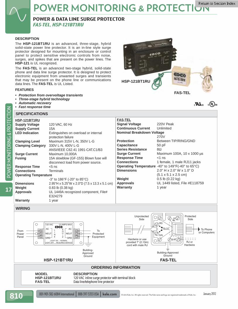
001-901-382-6084 International 888-397-5353 USA kele.com © 2012 Kele, Inc. All rights reserved. The Kele name and logo are registered trademarks of Kele, Inc.
POWER MONITORING & PROTECTION
810
POW
ER M
ON
ITO
RIN
G &
PRO
TECT
ION
17
January 2012
Building-ApprovedGround
UnprotectedSide
Hardwire or useprovided 7' (2.13m)cord with male RJ
TELCO
RD
GN
BL
SL-WT
ProtectedSide
RJ orHardwire
To Phoneor Computers
FAS-TELHSP-121BT1RU
Building-ApprovedGround
FromPowerPanel
ToProtectedEquipment
LIGHT ON - NORMALLIGHT OFF - REQUIRES SERVICE
GRD
NEUT
AC
120 VAC
GRD
NEUT
AC
15 AMPS MAX
LINE
EQUIP
ORDERING INFORMATION
POWER & DATA LINE SURGE PROTECTOR FAS-TEL, HSP-121BT1RU
HSP-121BT1RU Supply Voltage 120 VAC, 60 Hz Supply Current 15A LED Indication Extinguishes on overload or internal
protection failure Clamping Level Maximum 315V L-N, 350V L-G Clamping Category 330V L-N, 400V L-G ANSI/IEEE C62.41 1991-CAT.C1/B3 Surge Current Maximum 10,000A Fusing 15A slowblow (GF-15S) Blown fuse will
disconnect load from power source. Response Time <5 ns Connections Terminals Operating Temperature
-3° to 186°F (-20° to 85°C) Dimensions 2.95"H x 5.25"W x 2.0"D (7.5 x 13.3 x 5.1 cm) Weight 0 .83 lb (0.38 kg) Approvals UL 1449A recognized component, File#
E324279 Warranty 1 year
DESCRIPTION The HSP-121BT1RU is an advanced, three-stage, hybrid solid-state power line protector. It is an in-line style surge protector designed for mounting in an enclosure or control panel to protect sensitive electronic controls from noise, surges, and spikes that are present on the power lines. The HSP-121 is UL recognized.The FAS-TEL is an advanced two-stage hybrid, solid-state phone and data line surge protector. It is designed to protect electronic equipment from unwanted surges and transients that may be present on the phone line or communications data lines. The FAS-TEL is UL Listed.
FEATURES
• Protection from overvoltage transients• Three-stage hybrid technology• Automatic recovery• Fast response time
SPECIFICATIONS
HSP-121BT1RU
MODEL DESCRIPTION HSP-121BT1RU 120 VAC inline surge protector with terminal block FAS-TEL Data line/telephone line protector
FAS-TEL
WIRING
FAS-TEL Signal Voltage 220V Peak Continuous Current Unlimited Nominal Breakdown Voltage
270V Protection Between TIP/RING/GND Capacitance 50 pF Series Resistance 8Ω Surge Current Maximum 100A, 10 x 1000 µs Response Time <1 ns Connections 1 female, 1 male RJ11 jacks Operating Temperature -40° to 149°F(-40° to 65°C) Dimensions 2.0" H x 2.0" W x 1.0" D
(5.1 x 5.1 x 2.5 cm) Weight 0 .5 lb (0.22 kg) Approvals UL 1449 listed, File #E118759 Warranty 1 year

© 2012 Kele, Inc. All rights reserved. The Kele name and logo are registered trademarks of Kele, Inc. kele.com 888-397-5353 USA 001-901-382-6084 International 811
POWER MONITORING & PROTECTIONPO
WER M
ON
ITORIN
G & PRO
TECTION
17
January 2012
ORDERING INFORMATION
LIGHTNING ARRESTER 392-SVSR2
Impulse Breakdown @100/V/µsec 300-750VDC Holder 150 VDC extinguishing in
less than 150 msInsulation Resistance (initial) <100 MΩCapacitance 5 pFImpulse Life Specifi cation Rated Heavy-Duty
80% survival to 400 surges of 500A
AC Discharge Current 65A, 11 cycle, 60 HzEnd-Of-Life Limits Insulation Resistance <1 MΩ DC Breakdown Voltage <180V Impulse Breakdown Voltage <900VVented (back-up) DC Breakdown Voltage <1600V (100-200 avg)Max Single Impulse Discharge Current 10 kA, 8 x 20 µsec surgeDimensions 3.5"H x 3.75"W x 2.5"D (8.9 x 9.5 x 6.4 cm)Weight 0.85 lb (0.39 kg)Approvals UL listed File #E2332
DESCRIPTION
The Model 392-SVSR2 is a two-pair gas tube lightning arrester in a plastic outdoor enclosure. It protects the communication lines that run between buildings against high voltage transients caused by motors, transmitters, lightning, etc.
Transients can be harmful and even capable of destroying bui ld ing automation systems. I t is recommended that the Model 392-SVSR2 be used at all points where communication cables exit or enter a building. To protect low voltage communication inputs on Building Automation Systems, this device should be used in conjunction with an appropriate voltage level surge protector such as a Model DTK-2LVLP.
If a shield is used, then ground at one end only.
Use #6 AWG solid wire to copper clad steel ground rod (min. 8'/2.4m deep) through shortest path with no sharp bends.
(white) (white)
(orange)(red) (red)
(blue) (blue)
(orange)
392-SVSR2
Notes: To protect low-voltage communication circuits, this device should be used in conjunction with an appropriate voltage level surge protector such as the Model DTK-2LVLP.
When applying surge protectors, use of the protection zone concept is recommended.
WIRING
SPECIFICATIONS 392-SVSR2
MODEL DESCRIPTION 392-SVSR2 Lightning arrester

001-901-382-6084 International 888-397-5353 USA kele.com © 2012 Kele, Inc. All rights reserved. The Kele name and logo are registered trademarks of Kele, Inc.
POWER MONITORING & PROTECTION
812
POW
ER M
ON
ITO
RIN
G &
PRO
TECT
ION
17
January 2012
ORDERING INFORMATION
METAL OXIDE VARISTOR, TRANSZORB V130LA1, V39ZA1, V47ZA1, 1.5KE56CA
DESCRIPTION
Metal Oxide Varistor (MOV) and Transzorb Voltage Transient Suppressors reduce high voltage spikes that could damage or confuse sensitive electronic circuits. Voltage spikes often will cause digital logic circuits to select an incorrect logic state or lock up entirely.
Power Transformer
120 VAC 24 VAC
120VMOV
24VMOV
Suppresses external voltage spikes coming from the power distribution bus and the spikes fromswitching the power transformer off.
Circuit Hot
Circuit Return
MOV(both places)
Reduces mechanical switch arcs and electronicswitch over-voltage breakdown. MOV voltageshould match load circuit voltage.
Inductive Load(relay, EP valve, etc.)
Load Switch(mechanical or electrical)
Transformer Installation
Coil and Switch Installation
WIRING
V130LA1
CAUSES OF VOLTAGE SPIKES
Voltage spikes appear in the user's circuit in three main ways:
1. Voltage spikes come in on the power distribution bus and are coupled to the user's circuits by the winding-to-winding capacitance of the user's power transformers.
2. Voltage spikes are generated in the power transformer secondary when the power transformer primary is turned off and the transformer's magnetic fi eld collapses.
3. Voltage spikes are generated within the user's circuits when an inductive load is switched off and the load's magnetic fi eld collapses. Voltage noise is also generated at the switched contacts and is radiated to the wires leading to the user's microprocessor.
OPERATIONWhen a voltage at or below the suppressor's nominal voltage is applied, the suppressor acts essentially like an open circuit. When a high-voltage spike appears across the suppressor the suppressor conducts or turns on, shunting the excess energy to the circuit return path, thereby reducing the amplitude of the voltage spike. When the voltage spike subsides, the suppressor reverts back to its open circuit state. MOV suppressors are bi-directional and can be used to protect both AC and DC circuits. They provide a somewhat soft clamping action in that the amplitude of the reduced voltage spike rises noticeably with the amount of energy contained in the spike. Transzorb suppressors come in unidirectional and bi-directional versions. The uni-directional versions are polarity-sensitive and can only be used in DC applications. The bi-directional versions may be used in both AC and DC circuits just like the MOV. Transzorbs have a faster response time and a much harder clamping action than MOVs because voltage spikes are clipped at a more consistent level independent of their energy content. The Transzorb sold by Kele is a bi-directional version. Note: Kele carries the varistors and transzorbs most often specified by the BAS manufacturers. They are general-purpose in nature and should cover most applications at the recommended voltage.
MODEL DESCRIPTION V130LA1 130 VAC/175 VDC varistor voltage transient suppressor V39ZA1 25 VAC/31 VDC varistor voltage transient suppressor V47ZA1 30 VAC/38 VDC varistor voltage transient suppressor 1.5KE56CA 24 VAC/VDC transzorb voltage transient suppressor
V39ZA1
V47ZA1
1.5KE56CA
V130LA UL-recognized component, File #E75961 and E56529V39ZA1/V47ZA1 UL-recognized component, File #E1350101.5KE56CA UL-recognized component, File #E116110
AGENCY APPROVALS
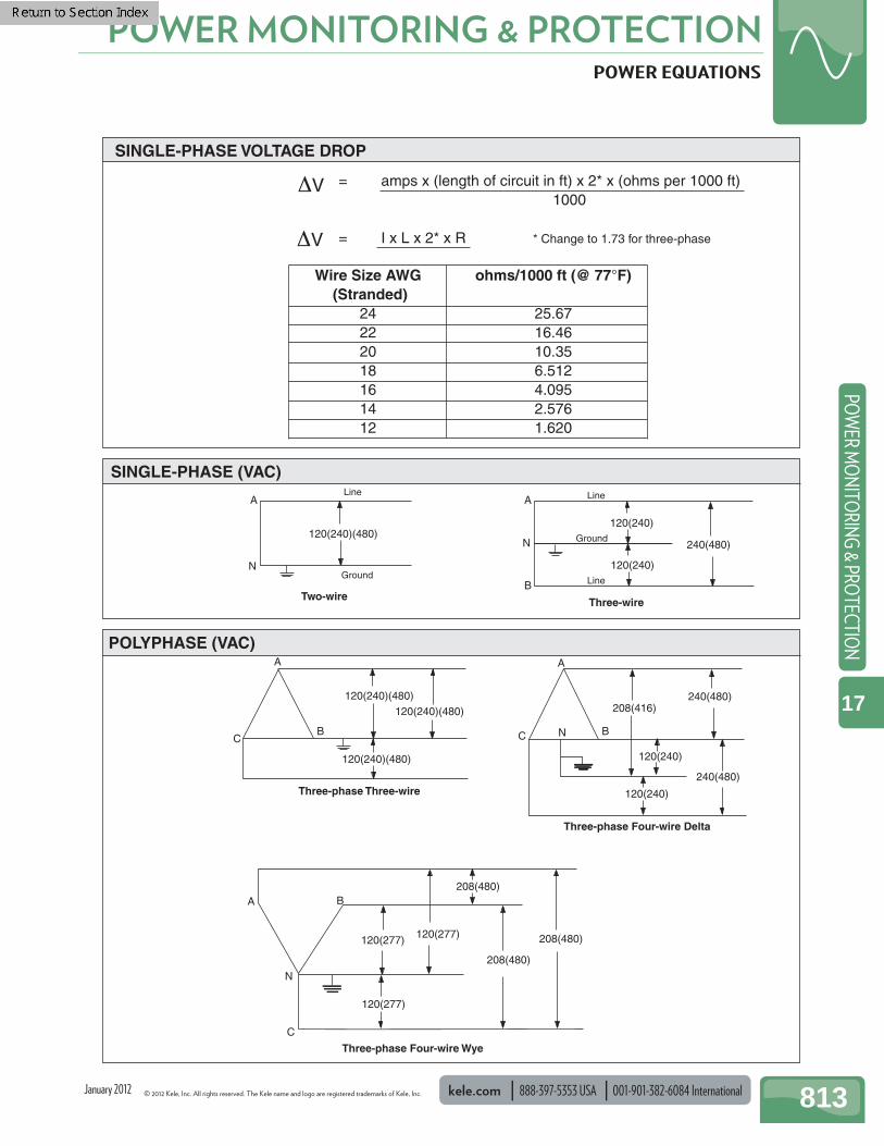
© 2012 Kele, Inc. All rights reserved. The Kele name and logo are registered trademarks of Kele, Inc. kele.com 888-397-5353 USA 001-901-382-6084 International 813
POWER MONITORING & PROTECTIONPO
WER M
ON
ITORIN
G & PRO
TECTION
17
January 2012
POWER EQUATIONS
A
CB
120(240)(480)120(240)(480)
120(240)(480)
Three-phase Three-wire
POLYPHASE (VAC)
SINGLE-PHASE (VAC)
A
C B
208(416)240(480)
120(240)
Three-phase Four-wire Delta
120(240)
240(480)
120(277)
120(277)
120(277) 208(480)
208(480)
208(480)
Three-phase Four-wire Wye
C
BA
N
N
A
120(240)(480)
Two-wire
NGround
LineA
120(240)
Three-wire
N Ground
Line
120(240)
B
240(480)
Line
= amps x (length of circuit in ft) x 2* x (ohms per 1000 ft) 1000
= I x L x 2* x R * Change to 1.73 for three-phase
SINGLE-PHASE VOLTAGE DROP
ΔV
ΔV
Wire Size AWG ohms/1000 ft (@ 77°F) (Stranded) 24 25.67 22 16.46 20 10.35 18 6.512 16 4.095 14 2.576 12 1.620
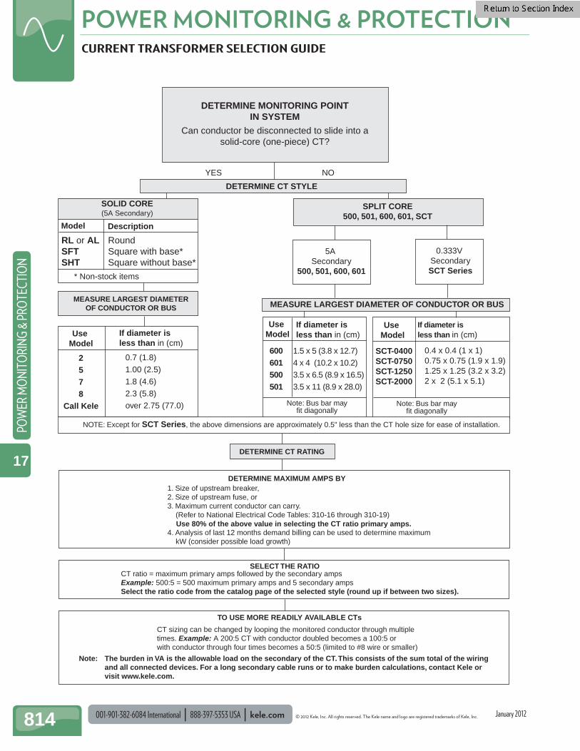
001-901-382-6084 International 888-397-5353 USA kele.com © 2012 Kele, Inc. All rights reserved. The Kele name and logo are registered trademarks of Kele, Inc.
POWER MONITORING & PROTECTION
814
POW
ER M
ON
ITO
RIN
G &
PRO
TECT
ION
17
January 2012
CURRENT TRANSFORMER SELECTION GUIDE
DETERMINE MONITORING POINTIN SYSTEM
Can conductor be disconnected to slide into asolid-core (one-piece) CT?
MEASURE LARGEST DIAMETEROF CONDUCTOR OR BUS
YES NO
DETERMINE CT STYLE
Model Description
RL or ALSFTSHT
* Non-stock items
Use Model
If diameter isless than in (cm)
2578
Call Kele
0.7 (1.8)1.00 (2.5)1.8 (4.6)2.3 (5.8)over 2.75 (77.0)
SOLID CORE(5A Secondary)
SPLIT CORE500, 501, 600, 601, SCT
5A Secondary
500, 501, 600, 601
MEASURE LARGEST DIAMETER OF CONDUCTOR OR BUS
Use Model
If diameter isless than in (cm)
If diameter isless than in (cm)
600 1.5 x 5 (3.8 x 12.7)601 4 x 4 (10.2 x 10.2)500 3.5 x 6.5 (8.9 x 16.5)501 3.5 x 11 (8.9 x 28.0)
Note: Bus bar mayfit diagonally
DETERMINE CT RATING
1. Size of upstream breaker,2. Size of upstream fuse, or3. Maximum current conductor can carry. (Refer to National Electrical Code Tables: 310-16 through 310-19)
4. Analysis of last 12 months demand billing can be used to determine maximum kW (consider possible load growth)
Use 80% of the above value in selecting the CT ratio primary amps.
SELECT THE RATIO
TO USE MORE READILY AVAILABLE CTs
Note:
CT ratio = maximum primary amps followed by the secondary ampsExample: 500:5 = 500 maximum primary amps and 5 secondary ampsSelect the ratio code from the catalog page of the selected style (round up if between two sizes).
CT sizing can be changed by looping the monitored conductor through multipletimes. Example: A 200:5 CT with conductor doubled becomes a 100:5 orwith conductor through four times becomes a 50:5 (limited to #8 wire or smaller)
The burden in VA is the allowable load on the secondary of the CT. This consists of the sum total of the wiringand all connected devices. For a long secondary cable runs or to make burden calculations, contact Kele orvisit www.kele.com.
RoundSquare with base*Square without base*
0.333V SecondarySCT Series
Use Model
SCT-0400SCT-0750SCT-1250SCT-2000
0.4 x 0.4 (1 x 1)0.75 x 0.75 (1.9 x 1.9)1.25 x 1.25 (3.2 x 3.2)2 x 2 (5.1 x 5.1)
Note: Bus bar mayfit diagonally
NOTE: Except for SCT Series, the above dimensions are approximately 0.5" less than the CT hole size for ease of installation.
DETERMINE MAXIMUM AMPS BY
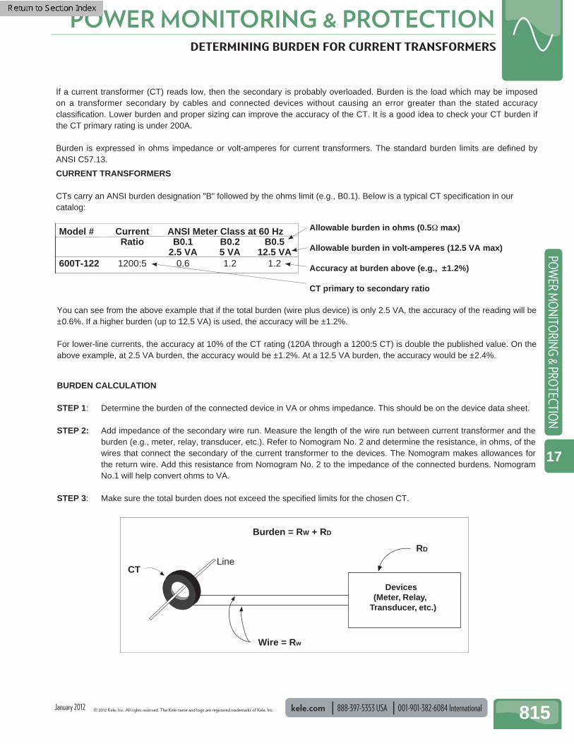
© 2012 Kele, Inc. All rights reserved. The Kele name and logo are registered trademarks of Kele, Inc. kele.com 888-397-5353 USA 001-901-382-6084 International 815
POWER MONITORING & PROTECTIONPO
WER M
ON
ITORIN
G & PRO
TECTION
17
January 2012
DETERMINING BURDEN FOR CURRENT TRANSFORMERS
You can see from the above example that if the total burden (wire plus device) is only 2.5 VA, the accuracy of the reading will be ±0.6%. If a higher burden (up to 12.5 VA) is used, the accuracy will be ±1.2%.
For lower-line currents, the accuracy at 10% of the CT rating (120A through a 1200:5 CT) is double the published value. On the above example, at 2.5 VA burden, the accuracy would be ±1.2%. At a 12.5 VA burden, the accuracy would be ±2.4%.
BURDEN CALCULATION
STEP 1: Determine the burden of the connected device in VA or ohms impedance. This should be on the device data sheet.
STEP 2: Add impedance of the secondary wire run. Measure the length of the wire run between current transformer and the burden (e.g., meter, relay, transducer, etc.). Refer to Nomogram No. 2 and determine the resistance, in ohms, of the wires that connect the secondary of the current transformer to the devices. The Nomogram makes allowances for the return wire. Add this resistance from Nomogram No. 2 to the impedance of the connected burdens. Nomogram No.1 will help convert ohms to VA.
STEP 3: Make sure the total burden does not exceed the specifi ed limits for the chosen CT.
If a current transformer (CT) reads low, then the secondary is probably overloaded. Burden is the load which may be imposed on a transformer secondary by cables and connected devices without causing an error greater than the stated accuracy classifi cation. Lower burden and proper sizing can improve the accuracy of the CT. It is a good idea to check your CT burden if the CT primary rating is under 200A.
Burden is expressed in ohms impedance or volt-amperes for current transformers. The standard burden limits are defi ned by ANSI C57.13.
CURRENT TRANSFORMERS
CTs carry an ANSI burden designation "B" followed by the ohms limit (e.g., B0.1). Below is a typical CT specifi cation in our catalog:
Allowable burden in ohms (0.5Ω max) Allowable burden in volt-amperes (12.5 VA max) Accuracy at burden above (e.g., ±1.2%) CT primary to secondary ratio
Model # Current ANSI Meter Class at 60 Hz Ratio B0.1 B0.2 B0.5 2.5 VA 5 VA 12.5 VA600T-122 1200:5 0.6 1.2 1.2
Line CT
Devices(Meter, Relay,
Transducer, etc.)
RD
Wire = Rw
Burden = RW + RD
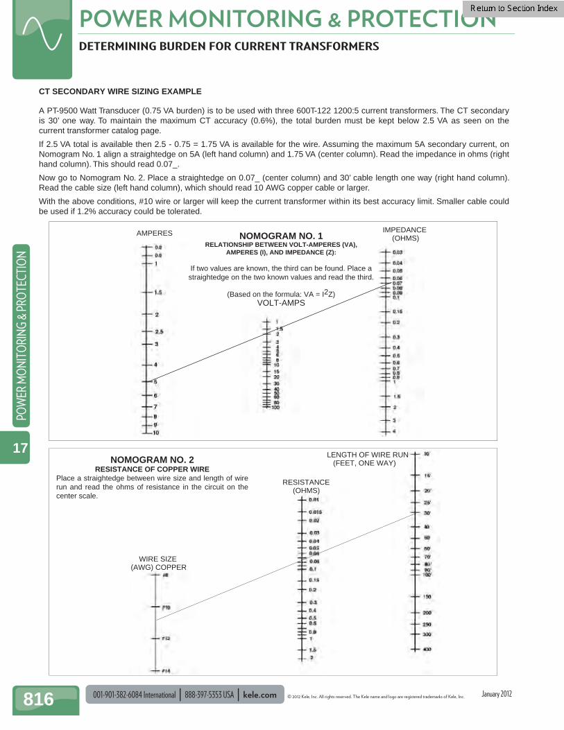
001-901-382-6084 International 888-397-5353 USA kele.com © 2012 Kele, Inc. All rights reserved. The Kele name and logo are registered trademarks of Kele, Inc.
POWER MONITORING & PROTECTION
816
POW
ER M
ON
ITO
RIN
G &
PRO
TECT
ION
17
January 2012
DETERMINING BURDEN FOR CURRENT TRANSFORMERS
CT SECONDARY WIRE SIZING EXAMPLE
A PT-9500 Watt Transducer (0.75 VA burden) is to be used with three 600T-122 1200:5 current transformers. The CT secondary is 30’ one way. To maintain the maximum CT accuracy (0.6%), the total burden must be kept below 2.5 VA as seen on the current transformer catalog page.
If 2.5 VA total is available then 2.5 - 0.75 = 1.75 VA is available for the wire. Assuming the maximum 5A secondary current, on Nomogram No. 1 align a straightedge on 5A (left hand column) and 1.75 VA (center column). Read the impedance in ohms (right hand column). This should read 0.07_.
Now go to Nomogram No. 2. Place a straightedge on 0.07_ (center column) and 30’ cable length one way (right hand column). Read the cable size (left hand column), which should read 10 AWG copper cable or larger.
With the above conditions, #10 wire or larger will keep the current transformer within its best accuracy limit. Smaller cable could be used if 1.2% accuracy could be tolerated.
IMPEDANCE (OHMS)
AMPERES NOMOGRAM NO. 1RELATIONSHIP BETWEEN VOLT-AMPERES (VA),
AMPERES (I), AND IMPEDANCE (Z):
If two values are known, the third can be found. Place a straightedge on the two known values and read the third.
(Based on the formula: VA = I2Z)VOLT-AMPS
RESISTANCE (OHMS)
LENGTH OF WIRE RUN (FEET, ONE WAY)
WIRE SIZE (AWG) COPPER
NOMOGRAM NO. 2RESISTANCE OF COPPER WIRE
Place a straightedge between wire size and length of wire run and read the ohms of resistance in the circuit on the center scale.
Related Documents