AIMB-340F Socket 478 EmbeddedATX SBC for Multimedia Applications Users Manual

Welcome message from author
This document is posted to help you gain knowledge. Please leave a comment to let me know what you think about it! Share it to your friends and learn new things together.
Transcript

AIMB-340FSocket 478 EmbeddedATX SBC for Multimedia Applications
User�s Manual

CopyrightThis document is copyrighted, © 2003. All rights are reserved. The origi-nal manufacturer reserves the right to make improvements to the products described in this manual at any time without notice.No part of this manual may be reproduced, copied, translated or transmit-ted in any form or by any means without the prior written permission of the original manufacturer. Information provided in this manual is intended to be accurate and reliable. However, the original manufacturer assumes no responsibility for its use, nor for any infringements upon the rights of third parties that may result from such use.AcknowledgementsAward is a trademark of Award Software International, Inc. VIA is a trademark of VIA Technologies, Inc. IBM, PC/AT, PS/2 and VGA are trademarks of International Business Machines Corporation. Intel and Pentium are trademarks of Intel Corporation. Microsoft Windows® is a registered trademark of Microsoft Corp. RTL is a trademark of Realtek Semi-Conductor Co., Ltd. ESS is a trademark of ESS Technology, Inc. UMC is a trademark of United Microelectronics Corporation. SMI is a trademark of Silicon Motion, Inc. Creative is a trademark of Creative Technology LTD. All other product names or trademarks are properties of their respective owners.
For more information on this and other Advantech products, please visit our websites at: http://www.advantech.com
http://www.advantech.com/epcFor technical support and service, please visit our support website at:
http://support.advantech.comThis manual is for the AIMB-340F Series.
Part No. 2006034000
1st Edition, August 2003
AIMB-340F User�s Manual ii

Packing List Before you begin installing your card, please make sure that the following materials have been shipped:� 1 AIMB-340 all-in one single board computer� 1 CD-ROM or disks for utility, drivers, and manual (in PDF format)� 1 warranty certificate� 1 UDMA 66 40-pin flat cable� 1 startup manual� 2 serial port cables� 1 4-port serial cable (AIMB-340F only)If any of these items are missing or damaged, contact your distributor or sales representative immediately.
iii

Additional Information and Assistance Step 1. Visit the Advantech web site at www.advantech.com where you
can find the latest information about the product.Step 2. Contact your distributor, sales representative, or Advantech's cus-
tomer service center for technical support if you need additional assistance. Please have the following information ready before you call:
� Product name and serial number� Description of your peripheral attachments� Description of your software (operating system, version, application
software, etc.)� A complete description of the problem� The exact wording of any error messages
AIMB-340F User�s Manual iv

Safety Instructions 1. Read these safety instructions carefully.2. Keep this User's Manual for later reference.3. Disconnect this equipment from any AC outlet before cleaning. Use a damp
cloth. Do not use liquid or spray detergents for cleaning.4. For plug-in equipment, the power outlet socket must be located near the
equipment and must be easily accessible.5. Keep this equipment away from humidity.6. Put this equipment on a reliable surface during installation. Dropping it or let-
ting it fall may cause damage.7. The openings on the enclosure are for air convection. Protect the equipment
from overheating. DO NOT COVER THE OPENINGS.8. Make sure the voltage of the power source is correct before connecting the
equipment to the power outlet.9. Position the power cord so that people cannot step on it. Do not place anything
over the power cord.10. All cautions and warnings on the equipment should be noted.11. If the equipment is not used for a long time, disconnect it from the power
source to avoid damage by transient overvoltage.12. Never pour any liquid into an opening. This may cause fire or electrical shock.13. Never open the equipment. For safety reasons, the equipment should be
opened only by qualified service personnel.14. If one of the following situations arises, get the equipment checked by service
personnel:a. The power cord or plug is damaged.b. Liquid has penetrated into the equipment.c. The equipment has been exposed to moisture.d. The equipment does not work well, or you cannot get it to work according
to the user's manual.e. The equipment has been dropped and damaged.f. The equipment has obvious signs of breakage.
15. DO NOT LEAVE THIS EQUIPMENT IN AN ENVIRONMENT WHERE THE STORAGE TEMPERATURE MAY GO BELOW -20° C (-4° F) OR ABOVE 60° C (140° F). THIS COULD DAMAGE THE EQUIPMENT. THE EQUIPMENT SHOULD BE IN A CONTROLLED ENVIRONMENT.
16. CAUTION: DANGER OF EXPLOSION IF BATTERY IS INCORRECTLY REPLACED.REPLACE ONLY WITH THE SAME OR EQUIVALENT TYPE RECOMMENDED BY THE MANUFACTURER, DISCARD USED BATTERIES ACCORDING TO THE MANUFACTURER'S INSTRUC-TIONS.
The sound pressure level at the operator's position according to IEC 704-1:1982 is no more than 70 dB (A).DISCLAIMER: This set of instructions is given according to IEC 704-1. Advan-tech disclaims all responsibility for the accuracy of any statements contained herein.
v

Wichtige Sicherheishinweise 1. Bitte lesen sie Sich diese Hinweise sorgfältig durch.2. Heben Sie diese Anleitung für den späteren Gebrauch auf.3. Vor jedem Reinigen ist das Gerät vom Stromnetz zu trennen. Verwenden Sie
Keine Flüssig-oder Aerosolreiniger. Am besten dient ein angefeuchtetes Tuch zur Reinigung.
4. Die NetzanschluBsteckdose soll nahe dem Gerät angebracht und leicht zugänglich sein.
5. Das Gerät ist vor Feuchtigkeit zu schützen.6. Bei der Aufstellung des Gerätes ist auf sicheren Stand zu achten. Ein Kippen
oder Fallen könnte Verletzungen hervorrufen.7. Die Belüftungsöffnungen dienen zur Luftzirkulation die das Gerät vor überhit-
zung schützt. Sorgen Sie dafür, daB diese Öffnungen nicht abgedeckt werden.8. Beachten Sie beim. AnschluB an das Stromnetz die AnschluBwerte.9. Verlegen Sie die NetzanschluBleitung so, daB niemand darüber fallen kann.
Es sollte auch nichts auf der Leitung abgestellt werden.10. Alle Hinweise und Warnungen die sich am Geräten befinden sind zu
beachten.11. Wird das Gerät über einen längeren Zeitraum nicht benutzt, sollten Sie es vom
Stromnetz trennen. Somit wird im Falle einer Überspannung eine Beschädi-gung vermieden.
12. Durch die Lüftungsöffnungen dürfen niemals Gegenstände oder Flüssigkeiten in das Gerät gelangen. Dies könnte einen Brand bzw. elektrischen Schlag aus-lösen.
13. Öffnen Sie niemals das Gerät. Das Gerät darf aus Gründen der elektrischen Sicherheit nur von authorisiertem Servicepersonal geöffnet werden.
14. Wenn folgende Situationen auftreten ist das Gerät vom Stromnetz zu trennen und von einer qualifizierten Servicestelle zu überprüfen:a - Netzkabel oder Netzstecker sind beschädigt.b - Flüssigkeit ist in das Gerät eingedrungen.c - Das Gerät war Feuchtigkeit ausgesetzt.d - Wenn das Gerät nicht der Bedienungsanleitung entsprechend funktioniert
oder Sie mit Hilfe dieser Anleitung keine Verbesserung erzielen.e - Das Gerät ist gefallen und/oder das Gehäuse ist beschädigt.f - Wenn das Gerät deutliche Anzeichen eines Defektes aufweist.
15. VOSICHT: Explisionsgefahr bei unsachgemaben Austausch der Batte-rie.Ersatz nur durch densellben order einem vom Hersteller empfohlene-mahnlichen Typ. Entsorgung gebrauchter Batterien navh Angaben des Herstellers.
Der arbeitsplatzbezogene Schalldruckpegel nach DIN 45 635 Teil 1000 beträgt 70dB(A) oder weiger.DISCLAIMER: This set of instructions is given according to IEC704-1. Advantech disclaims all responsibility for the accuracy of any statements contained herein.
AIMB-340F User�s Manual vi

Caution! Danger of explosion if battery is incorrectly replaced. Replace only with the same or equiv-alent type recommended by the manufacturer. Dispose of used batteries according to the man-ufacturer�s instructions.
vii

AIMB-340F User�s Manual viii

ContentsChapter 1 General Information ........................................2
1.1 Introduction ....................................................................... 21.2 Features ............................................................................. 31.3 Specifications .................................................................... 41.4 Board Dimensions ............................................................. 6
Figure 1.1:Board Dimensions (Component Side)........... 6Figure 1.2:Board Dimensions (Solder Side)................... 7
Chapter 2 Installation ......................................................102.1 Jumpers............................................................................ 10
Table 2.1:Table 2.1: Jumpers........................................ 102.2 Connectors....................................................................... 10
Table 2.2:Connectors .................................................... 102.3 Locating jumpers and connectors.................................... 12
Figure 2.1:Locating Jumpers & Connectors ................. 122.4 Setting Jumpers ............................................................... 132.5 CPU installation and upgrading ...................................... 14
2.5.1 Installing a CPU in the ZIF socket................................ 142.5.2 CMOS clear (SW2)....................................................... 15
2.6 DRAM installation .......................................................... 152.6.1 DDR SDRAM (DIMM 1 and DIMM 2)....................... 15
2.7 Primary (3.5") IDE connector (CN22) ............................ 162.7.1 Connecting the hard drive............................................. 16
2.8 Secondary (2.5") IDE connector (CN20) ........................ 162.9 FDD connector (CN23) (optional) .................................. 17
2.9.1 Connecting the floppy drive ......................................... 172.10 LPT1 (primary parallel port) connectors .............. (CN5)182.11 LPT2 (secondary parallel port) connector (CN26) ......... 182.12 Keyboard/mouse connectors (CN6) ................................ 182.13 Power connectors (CN18, CN12, FAN1, FAN2)............ 18
2.13.1 Main power connector (CN12) ..................................... 182.13.2 ATX power input connector (CN18) ............................ 182.13.3 Fan power supply connector (FAN2, FAN1) ............... 18
2.14 Audio interfaces (CN4, CN10, CN11) ............................ 192.14.1 Audio connector (CN4) ................................................ 192.14.2 Internal Speaker Connector (CN10) ............................. 192.14.3 CD audio-in connector (CN11)..................................... 19
2.15 Serial (COM1-6) (CN2, CN27, CN25) ........................... 192.15.1 Primary (COM1:CN2,COM2:CN27) ........................... 192.15.2 Secondary (COM3~COM6: CN25).............................. 19
2.16 COM-2 RS232/422/485 &COM 1-6 Ring select (9x2 ,
ix Table of Contents
2.0mm Pin-header) (JP4)202.17 COM1~COM6 Pin-9 voltage output select..................... 202.18 VGA interface connections ............................................. 22
2.18.1 CRT display connector (CN1) ...................................... 222.18.2 Flat panel display connector (CN13) ............................ 222.18.3 LCD VDDSAFE setting (JP2)...................................... 23
Table 2.3:LCD power (JP2).......................................... 232.18.4 Inverter power connector (CN17)................................. 23
2.19 Ethernet configuration..................................................... 232.19.1 RJ-45 connector (CN9)................................................. 232.19.2 Network boot ................................................................ 23
2.20 Watchdog timer configuration ........................................ 242.21 USB connector (CN7,CN9,CN16) .................................. 242.22 Digital I/O (CN19: 4 Outputs, 4 Inputs) ......................... 24
2.22.1 Digital output programming ......................................... 25Table 2.4:Digital output programming ......................... 25
2.23 IrDA Connector (CN21).................................................. 252.24 System LED (CN24) ....................................................... 252.25 Host bus speed select (JP1) ............................................. 25
Table 2.5:-> Host bus speed sel. ................................... 252.26 Watch Dog programer (CN15)........................................ 262.27 PCI slot expension (PCI1 or PCI2) ................................. 26
Chapter 3 Chipset Software Installation Utility ............283.1 Before you begin ............................................................. 283.2 Introduction ..................................................................... 283.3 Installing the CSI Utility ................................................. 293.4 Connections for Standard LCDs ..................................... 32
Table 3.1:LCD connections .......................................... 32
Chapter 4 Audio Setup.....................................................344.1 Introduction ..................................................................... 344.2 Driver installation............................................................ 34
4.2.1 Before you begin........................................................... 34
Chapter 5 Award BIOS Setup.........................................425.1 Introduction ..................................................................... 42
5.1.1 CMOS RAM Auto-backup and Restore ....................... 425.2 Entering Setup ................................................................. 43
Figure 5.1:Award BIOS Setup initial screen ................ 435.3 Standard CMOS Setup .................................................... 44
Figure 5.2:Standard CMOS features screen ................. 445.4 Advanced BIOS Features ................................................ 44
Figure 5.3:Advanced BIOS features screen.................. 455.4.1 Virus Warning............................................................... 45
AIMB-340F User�s Manual x

5.4.2 L1 & L2 Cache ............................................................. 455.4.3 Quick Power On Self Test ............................................ 455.4.4 First/Second/Third/Other Boot Device......................... 455.4.5 Swap Floppy Drive ....................................................... 455.4.6 Boot UP Floppy Seek ................................................... 455.4.7 Boot Up NumLock Status............................................. 465.4.8 Gate A20 Option........................................................... 465.4.9 Typematic Rate Setting................................................. 465.4.10 Typematic Rate (Chars/Sec) ......................................... 465.4.11 Typematic Delay (msec)............................................... 465.4.12 Security Option ............................................................. 465.4.13 APIC Mode................................................................... 465.4.14 MPS Version Control For OS....................................... 47
5.5 Integrated Peripherals...................................................... 475.5.1 IDE Master/Slave PIO/UDMA Mode,.......................... 475.5.2 On-Chip Secondary PCI IDE........................................ 47
Figure 5.4:Integrated peripherals.................................. 475.5.3 USB Controller ............................................................. 485.5.4 USB Keyboard/Mouse Support .................................... 485.5.5 AC97 Audio.................................................................. 485.5.6 Init Display First ........................................................... 485.5.7 Onboard LAN Control .................................................. 485.5.8 IDE HDD Block Mode ................................................. 485.5.9 Onboard FDC Controller .............................................. 485.5.10 Onboard Serial Port ...................................................... 485.5.11 UART Mode Select ...................................................... 485.5.12 RxD, TxD Active.......................................................... 485.5.13 IR Transmission Delay ................................................. 485.5.14 UR2 Duplex Mode........................................................ 495.5.15 Onboard Parallel Port.................................................... 495.5.16 Parallel Port Mode ........................................................ 495.5.17 EPP Mode Select .......................................................... 495.5.18 ECP Mode Use DMA ................................................... 49
5.6 Power Management Setup............................................... 50Figure 5.5:Power management setup screen................. 50
5.6.1 Power-Supply Type ..................................................... 505.6.2 ACPI function ............................................................... 505.6.3 Power Management ...................................................... 505.6.4 Video Off In Suspend .................................................. 515.6.5 Modem Use IRQ........................................................... 515.6.6 HDD Power Down........................................................ 515.6.7 Soft-Off by PWR-BTTN .............................................. 515.6.8 CPU THRM-Throttling................................................. 515.6.9 PowerOn By LAN ........................................................ 515.6.10 PowerOn By Modem .................................................... 51
xi Table of Contents

5.6.11 PowerOn By Alarm ...................................................... 515.6.12 Primary IDE 0 (1) and Secondary IDE 0 (1) ................ 515.6.13 FDD, COM, LPT PORT............................................... 525.6.14 PCI PIRQ [A-D]# ........................................................ 52
5.7 PnP/PCI Configurations .................................................. 525.7.1 PnP OS Installed ........................................................... 52
Figure 5.6:PnP/PCI configurations screen.................... 525.7.2 Reset Configuration Data.............................................. 525.7.3 Resources controlled by:............................................... 525.7.4 PCI/VGA Palette Snoop ............................................... 53
5.8 PC Health Status.............................................................. 535.8.1 CPU Warning Temperature .......................................... 53
Figure 5.7:PC health status screen................................ 535.8.2 Current CPU Temperature ............................................ 535.8.3 Current CPUFAN Speed............................................... 535.8.4 +5V/+12V/-12V/-5V .................................................... 53
5.9 Password Setting ............................................................. 545.10 Save & Exit Setup ........................................................... 545.11 Exit Without Saving ........................................................ 55
Chapter 6 VGA Setup ......................................................586.1 Introduction ..................................................................... 586.2 Dynamic Video Memory Technology............................. 586.3 Windows 9x/2000/Me/XP Installation ........................... 59
6.3.1 Installation for Windows NT ........................................ 63
Chapter 7 PCI Bus Ethernet Interface...........................707.1 Introduction ..................................................................... 707.2 Features ........................................................................... 707.3 Installation of Ethernet Driver......................................... 70
7.3.1 Installation for Windows 2000 ..................................... 717.3.2 Installation for Windows NT ........................................ 75
7.4 Further information ......................................................... 81Appendix A Programming the Watchdog Timer .............84
A.1 Programming the watchdog timer ................................... 84Appendix B Sample Code of GPIO programming...........88Appendix C AIMB-340 Jumper and Connector Settings 92
C.1 Connectors ...................................................................... 92Table C.1:Connectors ................................................... 92
C.2 CN1 VGA D-TYPE 15 Pins connector........................... 93C.3 CN2 COM1 D-TYPE 9 Pins connect.............................. 93C.4 CN3 S-Video output (4 Pin 2.0mm wafer box) .............. 94C.5 CN4 Audio connector...................................................... 94C.6 CN25 LPT1 D-TYPE 25 Pin connector.......................... 94
AIMB-340F User�s Manual xii

C.7 CN26 USB2.0 1 & 2 connect .......................................... 95C.8 CN8 Internal speaker(4x1,2.0mm Wafer-box) ............... 95C.9 CN11 CD-Input connector (4x1,2.54 mm Wafer-box) ... 95
C.10 CN12 +12V Power connector (2x2) ............................... 96C.11 CN13 LVDS (20x2,DF13 connector) ............................. 97C.12 CN15 Reserved to program the Watch-dog .................... 98C.13 CN16 Embedded USB (9x2,2.54 mm Pin-header) ......... 98C.14 CN17 Inverter power(5x1,2.0 mm Wafer-box) .............. 99C.15 CN18 ATX Power connector (10x2,ATX) ..................... 99C.16 CN19 DIO Connector(8x2,2.54mm pin-header)........... 100C.17 CN20 Secondary IDE(22x2 ,2.0mm Box-header) ........ 100C.18 CN21 IrDA Connector(5x1,2.54mm Pin-header) ......... 101C.19 CN22 Primary IDE(20x2 , 2.54mm Box-header) ......... 102C.20 CN23 Floppy(26 Pin FDC connector)(optional)........... 103C.21 CN24 ATX pwr/Reset/LED (7x2 , 2.54mm pin ........... 104C.22 CN25 COM3 - COM6(20x2 , 2.0 mm Box-header) ..... 104C.23 CN26 PRN2(13x2,2.0 mm Box-header) ....................... 105C.24 CN27 COM-2(7x2,2.0mm Box-header) ....................... 105C.25 FAN1 CPU FAN (3x1,2.54 mm Molex)....................... 106C.26 FAN2 System FAN (3x1,2.54 mm Molex)................... 106C.27 JP1 Host bus speed sel.(3x1,2.0 mm Pin-header) ......... 106C.28 JP2 LVDS VDDSAFE sel.(3x1,2.0 mm Pin-header).... 106C.29 JP3 COM1-6 Pin-9 V out (11x2,2.0mm Pin-header).... 107C.30 JP4 COM-2 RS232/422/485 and COM-1 to COM-6 Ring signal select (9x2 , 2.0mm Pin-header)108
Appendix D IRQ Resources ..............................................112D.1 IRQ Resource Guide ..................................................... 112
xiii Table of Contents

AIMB-340F User�s Manual xiv

CH
AP
TE
R 1General Information
This chapter gives background infor-mation on the AIMB-340F.Sections include:
� Sections include:� Introduction� Features� Specifications� Board layout and dimensions

Chapter 1 General Information1.1 Introduction
The AIMB-340F utilizes an EmbeddedATX form factor (Socket 478) design that supports Celeron® processors and Pentium® 4 processors up to 3.06 GHz CPU with 533 MHz FSB. This effective EmbeddedATX socket 478 solution gives end users the choice of good, economical per-formance with the Celeron series processors, or the impressive perfor-mance of the Pentium 4 series. This processor flexibility combined with all the other on-board features, explains why the AIMB-340F is the new top-of-the-line Industrial Motherboard solution at Advantech.The AIMB-340F is loaded with special on-board features that rival full-size systems. It has standard 10/100Base-T PCI Ethernet, 2 channel 48-bit LVDS LCD panel support as well as SSD support for CompactFlash®. There is a Mini PCI socket for optional international version modem, plus optional support for AC97 3D stereo surround sound with speaker-out, CD-input, line-in, line-out and microphone. The AIMB-340F also includes two 184-pin DDR DIMM sockets for up to 2 GB total on-board memory.The AIMB-340F was designed using feedback and knowledge gained from our customers. It has more of the features our customers have requested. It is 100% PC compatible and is ready to handle the most chal-lenging Industrial motherboard environments. Besides the great onboard memory flexibility and capacity, the AIMB-340F has six on-board serial ports, each with +5/+12 V power, six USB connectors, watchdog timer and tough industrial grade construction. The Award 256 KB Flash BIOS supports Plug & Play, Boot from Ethernet, Boot from CD-ROM, Boot from Zip drive, Wake-on-Lan, Modem. All these features make the AIMB-340F a very "system integrator friendly" solution, perfect for han-dling gaming, ATM, kiosks and DVR multimedia applications in the harshest unmanned environments.
AIMB-340F User�s Manual 2

1.2 Features
� All-in-one design simplifies system integration and increases system stability
� Socket 478 supports Celeron and Pentium® 4 processors, up to 3.06 (400/533 MHz PSB) and above.
� 2 slot 184 pin non-ECC DDR SDRAM (200/266/333MHz DDR ) sup-ports up to 2 GB
� On-board POS features such as 2/6 x RS-232 with power and 6 x USB (EmbeddedUSB will use 2 USB resources, are included) interfaces for external peripherals.
� 100/10Base-T with RJ-45 connection for the most demanding network-ing environment
� Supports Mini PCI interface for optional modem� Supports wake-on LAN, modem� 16-bit full-duplex 3D audio optional for quality multimedia sound
applications � Special industrial features not found on conventional motherboards
include watchdog timer, SSD and High Drive digital I/O for driving cash drawer
� Standardized layout conforms to Intel EmbeddedATX format for easy installation within standard sized chassis
� Supports up to 2 channel 48-bit LVDS high resolution LCDs� Advanced CPU switching power technology for stable and low heat
CPU voltage power conversion� Supports CompactFlash� card
3 Chapter 1

1.3 Specifications
Standard SBC functions
� CPU: Socket 478 for Intel® Celeron�/Pentium 4 processor� BIOS: Award 256 KB Flash memory� Chipset: Intel 82845GV and 82801 (ICH4)� System memory: Two non-ECC DDR SDRAM sockets accept 128
MB ~ 2 GB SDRAM � Enhanced IDE interface: 2 x EIDE, 40-pin UDMA 66&100 and 44-
pin UDMA 33� FDD interface: Supports up to two FDDs (optional)� Serial ports: 2/6 serial RS-232 ports, COM1,3,4,5,6: RS-232, COM2:
RS-232/422/485, COM3~6 share IRQ. It will depend on the OS sup-port to have a share IRQ capability.
� Parallel port: 1/2 parallel ports, supports SPP/EPP/ECP mode� Infrared port: Shared with COM2. Transfer rates up to 1.15 Mbps� Keyboard/mouse connector: Supports standard PC/AT keyboard and
a PS/2 mouse� Power management: Supports power saving modes including Normal/
Standby/Suspend modes. APM 1.1 compliant� Watchdog timer: 62 level timer intervals� USB: Six universal serial bus ports (USB2.0), EmbeddedUSB will
occupy 2 USB resources.Solid state disk� Supports one 50-pin socket for CompactFlash� cardVGA/LCD interface� Chipset: Intel 82845GV, Intel Direct memory Execution mode to use
system memory.� Interface: On chip 4X AGP performance.� Display mode: Maximum 3D resoutionj supported: 600 x 1200 @ 32
bpp@85Hz, Maximum Video Overlay Display Resolution: 1600x1200@ 32bpp@60Hz, 1280x1024@32bpp@85Hz
Ethernet interface � Chipset: Intel 82562, Intel 82551QM, Intel 82551ER or Intel 82540
AIMB-340F User�s Manual 4

� Ethernet interface: PCI 10/100 Mbps Ethernet. IEEE 802.3 U proto-col compatible
� Connection: On-board RJ-45 connector� Built-in boot ROMAudio function� Chipset: Intel 82801DB� Audio controller: AC97 version 2.0 compliant interface� Audio interface: Microphone in, line in, CD audio in, line out, speaker
L and Speaker RMechanical and environmental� Power requirements: +12 V(system)@ 220 mA, +12 V(CPU)@ 4A,-
12V@ 70 mA,+5V@ 295 mA,+3.3 V@ 2.6A (Pentium4, 3.06 G, DDR333 256 M)
� Operating temperature: 0 ~ 60° C (32 ~ 140° F)� Dimensions (L x W): 244 x 244 mm (9.6" x 9.6")� Weight: 0.7 kg (1.2 lb)
5 Chapter 1

1.4 Board Dimensions
Figure 1.1: Board Dimensions (Component Side)
0.00
6.35
163.83
229.87
243.84
209.55
163.83
6.35
12.01
54.84
36.84
73.44
104.40
128.91
148.84
! 4 PTH
! 7 GND
AIMB-340F User�s Manual 6
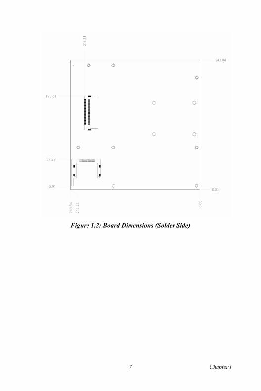
Figure 1.2: Board Dimensions (Solder Side)
0.00
243.84
5.91
57.29
175.61
7 Chapter 1

AIMB-340F User�s Manual 8
CH
AP
TE
R 2Installation
This chapter explains how to set up the AIMB-340F hardware, including instructions on setting jumpers and connecting peripherals, switches and indicators. Be sure to read all the safety precautions before you begin the instal-lation procedure.
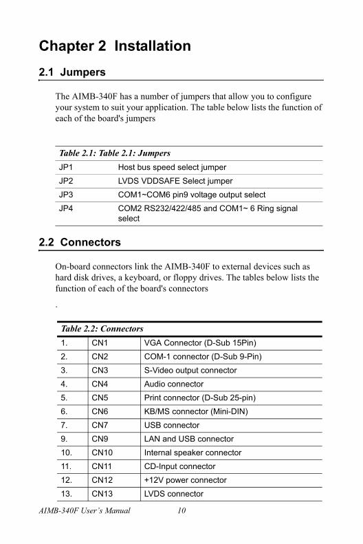
Chapter 2 Installation2.1 Jumpers
The AIMB-340F has a number of jumpers that allow you to configure your system to suit your application. The table below lists the function of each of the board's jumpers
2.2 Connectors
On-board connectors link the AIMB-340F to external devices such as hard disk drives, a keyboard, or floppy drives. The tables below lists the function of each of the board's connectors
.
Table 2.1: Table 2.1: JumpersJP1 Host bus speed select jumper
JP2 LVDS VDDSAFE Select jumper
JP3 COM1~COM6 pin9 voltage output select
JP4 COM2 RS232/422/485 and COM1~ 6 Ring signal select
Table 2.2: Connectors1. CN1 VGA Connector (D-Sub 15Pin)
2. CN2 COM-1 connector (D-Sub 9-Pin)
3. CN3 S-Video output connector
4. CN4 Audio connector
5. CN5 Print connector (D-Sub 25-pin)
6. CN6 KB/MS connector (Mini-DIN)
7. CN7 USB connector
9. CN9 LAN and USB connector
10. CN10 Internal speaker connector
11. CN11 CD-Input connector
12. CN12 +12V power connector
13. CN13 LVDS connector
AIMB-340F User�s Manual 10

15. CN15 Reserved for Watch-Dog programing
16. CN16 Embedded USB
17. CN17 Inverter Power Connector
18. CN18 ATX Power connector
19. CN19 DIO connector
20. CN20 2nd IDE connector
21. CN21 IrDA Connector
22. CN22 Primary IDE connector
23. CN23 Floppy connector
24. CN24 ATX Power/Reset/LED connector
25. CN25 COM3-COM6 connector
26. CN26 Print 2 connector
27. CN27 COM-2 connector
28. DIMM 1 DDR DIMM Socket
29. DIMM 2 DDR DIMM socket
30. FAN 1 CPU FAN
31. FAN2 System FAN
32. PCI1 PCI Slot-1
33. PCI2 PCI Slot-2 (optional)
34. SL1 AGP Slot (optional)
35. SW2 Clear CMOS switch
Table 2.2: Connectors
11 Chapter 2

2.3 Locating jumpers and connectors
Figure 2.1: Locating Jumpers & Connectors
CN21
CN19
CN17
FAN1
CN18
JP3JP4
CN27CN25CN24CN26FAN2CN22
CN23
CN16
CN15
PCI 1
PCI 2
CN13
CN14
JP2
CN3 CN10 CN11 CN4 CN9 CN7 CN1 CN2CN5 CN6
SL1
CN12
JP1
DIMM2
DIMM1
CN20
SW2
AIMB-340F User�s Manual 12

2.4 Setting Jumpers
You configure your board to match the needs of your application by set-ting jumpers. A jumper is the simplest kind of electric switch. It consists of two metal pins and a small metal clip (often protected by a plastic cover) that slides over the pins to connect them. To ìcloseî a jumper you connect the pins with the clip. To ìopenî a jumper you remove the clip. Sometimes a jumper will have three pins, labeled 1, 2, and 3. In this case you would connect either pins 1 and 2 or 2 and 3.
The jumper settings are schematically depicted in this manual as follows:
A pair of needle-nose pliers may be helpful when working with jumpers.If you have any doubts about the best hardware configuration for your application, contact your local distributor or sales representative before you make any changes.Generally, you simply need a standard cable to make most connections.
open closed closed 2-3
open closed closed 2-3
13 Chapter 2

2.5 CPU installation and upgrading
You can upgrade to a higher power Pentium 4 processor at any time. Sim-ply remove the old CPU, install the new one, and the BIOS will auto detect the new CPU type and speed.
2.5.1 Installing a CPU in the ZIF socketAIMB-340F provides a Zero Insertion Force (ZIF) socket for easy CPU installation.1. Make sure the ZIF socket lever is in the upright position. To raise
the lever, pull it out to the side a little and raise it as far as it will go.2. Place the CPU in the empty socket. Follow the instructions that
came with the CPU. If you have no instructions, do the following: Carefully align the CPU so it is parallel to the socket and the notch on the corner of the CPU corresponds with the notch on the inside of the socket. Gently slide the CPU in. It should insert easily. If it does not, pull the lever up a little more.
3. Press the lever down. The plate will slide forward. You will feel some resistance as the pressure starts to secure the CPU in the socket. This is normal and will not damage the CPU.
Warning! Always disconnect the power cord from your chassis when you are working on it. Do not make connections while the power is on as sensitive electronic components can be damaged by the sudden rush of power. Only experienced elec-tronics personnel should open the PC chassis
Caution! Always ground yourself to remove any static charge before touching the PC board. Modern electronic devices are very sensitive to static electric charges. Use a grounding wrist strap at all times. Place all electronic components on a static-dissipative surface or in a static-shielded bag when they are not in the chassis.
AIMB-340F User�s Manual 14

When the CPU is installed, the lever should snap into place at the side of the socket.
2.5.2 CMOS clear (SW2)
2.6 DRAM installation
There are two on-board 186-pin DDR DIMM sockets.
2.6.1 DDR SDRAM (DIMM 1 and DIMM 2)You can install one DDR SDRAM (up to 1 GB) or two 186-pin DIMM (up to 2 GB DRAM) in the DIMM sockets.
Note: To remove a CPU, pull the lever out to the side a little and raise it
Warning! To avoid damaging the computer, always unplug the power cord to turnoff the power supply before setting �Clear CMOS.� Use a pencil or a tool to press the tactile-switch.
Caution! When installing DIMM, make sure the module is oriented properly. Do not use excess force dur-ing installation.
15 Chapter 2

2.7 Primary (3.5") IDE connector (CN22)
The 40-pin IDE connector supports up to two 40-pin IDE interface devices, including CD-ROM drives, tape-backup drives, HDDs, etc. When connecting, make sure pin 1 of the connector is matched with pin of the device's connector.The built-in Enhanced IDE (Integrated Device Electronics) controller supports up to two IDE devices, including CD-ROM drives, tape backup drives, a large hard disk drive and other IDE devices. It also supports faster data transfer rates and allows IDE hard disk drives with capacities in excess of 528 MB.
2.7.1 Connecting the hard driveConnecting drives is done in a daisy-chain fashion. Wire number 1 on the cable is red or blue, while the other wires are gray.Unlike floppy drives, IDE hard drives can connect to either end of the cable. If you install two drives, you will need to set one as the master and one as the slave by using jumpers on the drives. If you install just one drive, set it as the master.
2.8 Secondary (2.5") IDE connector (CN20)
The on-board 44-pin mini-pitched IDE interface is used to let user sup-port either a 2.5" HDD.Follow the same connection arrangement as the 3.5" HDD if you want to connect to a 2.5" IDE device. Read the BIOS setup section for more information regarding system settings.
Note: You cannot use a DMA-66 HDD, due to the cableís limitation.
AIMB-340F User�s Manual 16

2.9 FDD connector (CN23) (optional)
You can attach up to two floppy disks to the AIMB-340F's on-board con-troller. You can use any combination of 5º" (360 KB and 1.2 MB) and/or 3¾" (720 KB, 1.44 MB, and 2.88 MB) drives.A 34-pin daisy-chain drive connector cable is required for a dual-drive system. On one end of the cable is a 34-pin flat-cable connector. On the other end are two sets of floppy disk drive connectors. Each set consists of a 34-pin flat-cable connector (usually used for 3¾" drives) and a printed-circuit board connector (usually used for 5º" drives).
2.9.1 Connecting the floppy driveUse Advantech 9681000044 FDD adaper to connector with CN23 on the AIMB-340F1. Plug the 34-pin flat-cable connector into 968100044 FDD connec-
tor. Make sure that the red wire corresponds to pin one on the con-nector.
2. Attach the appropriate connector on the other end of the cable to the floppy drive(s). You can use only one connector in the set. The set on the end (after the twist in the cable) connects to the A: drive. The set in the middle connects to the B: drive.
3. If you are connecting a 5º" floppy drive, line up the slot in the printed circuit board with the blocked-off part of the cable connec-tor. If you are connecting a 3¾" floppy drive, you may have trouble determining which pin is pin number one. Look for a number printed on the circuit board indicating pin number one. Also, the connector on the floppy drive connector may have a slot. When the slot is up, pin number one should be on the right. Check the docu-mentation that came with the drive for more information. The B: drive can be attached to the connectors in the middle of the cable as described above.
17 Chapter 2
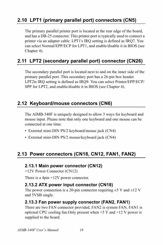
2.10 LPT1 (primary parallel port) connectors (CN5)
The primary parallel printer port is located at the rear edge of the board, and has a DB-25 connector. This printer port is typically used to connect a printer via an adapter cable. LPT1's IRQ setting is defined as IRQ7. You can select Normal/EPP/ECP for LPT1, and enable/disable it in BIOS (see Chapter 4).
2.11 LPT2 (secondary parallel port) connector (CN26)
The secondary parallel port is located next to and on the inner side of the primary parallel port. This secondary port has a 26-pin box header. LPT2ís IRQ setting is defined as IRQ9. You can select Printer/EPP/ECP/SPP for LPT2, and enable/disable it in BIOS (see Chapter 4).
2.12 Keyboard/mouse connectors (CN6)
The AIMB-340F is uniquely designed to allow 3 ways for keyboard and mouse input. Please note that only one keyboard and one mouse can be connected at one time.� External mini-DIN PS/2 keyboard/mouse jack (CN4)� External mini-DIN PS/2 mouse/keyboard jack (CN4)
2.13 Power connectors (CN18, CN12, FAN1, FAN2)
2.13.1 Main power connector (CN12)+12V Power Connector (CN12)There is a 4pin +12V power connector.
2.13.2 ATX power input connector (CN18)The power connection is a 20-pin connector requiring ±5 V and ±12 V and 5VSB single.
2.13.3 Fan power supply connector (FAN2, FAN1)There are two FAN connector provided, FAN2 is system FAN, FAN1 is optional CPU cooling fan.Only present when +5 V and +12 V power is supplied to the board.
AIMB-340F User�s Manual 18

2.14 Audio interfaces (CN4, CN10, CN11)
The AIMB-340FA is equipped with a high quality audio interface, which provides 16-bit CD-quality recording and playback as well as OPL3 com-patible FM music. It is supported by all major operating systems and is 100% Sound Blaster Pro compatible.
2.14.1 Audio connector (CN4)The AIMB-340FA provides all major audio signal connectors, CN4. These audio signals include Microphone in (mono), Line in (stereo), Line out (stereo).
2.14.2 Internal Speaker Connector (CN10)There is an internal speaker on CN10. It is a 4-pin box header connector.
2.14.3 CD audio-in connector (CN11)All CD-ROM drives can provide analog audio signal output when used as a music CD player. The CN11 on AIMB-340FA is a connector to input CD audio signal into the audio controller. The audio cable of your CD-ROM drive will be used to connect to CN11.
2.15 Serial (COM1-6) (CN2, CN27, CN25)
The AIMB-340F has a total of six/two on-board RS-232 serial ports, COM1,3,4,5,6: RS-232, COM2: RS-232/422/485, COM3~6 share IRQ. It will depend on the OS support to have a share IRQ capability. The OS which supports shared IRQs is Windows98/2000/XP. All serial ports have +5 V and +12 V power capabilities on both pin #1 and pin #9, depending on the jumper setting. Pin assignments for both internal and external COM ports can be found in the Appendix.
2.15.1 Primary (COM1:CN2,COM2:CN27)COM1:CN2 serial port is one external DB-9, COM2:CN27 is one internal 10-pin header giving the user the flexibility to adapt the board to many different systems. IRQ for COM1 and COM2 is fixed with COM1 on IRQ4 and COM2 on IRQ3. COM1 and COM2 can be enabled or disabled via BIOS (see Chapter 4).
2.15.2 Secondary (COM3~COM6: CN25)The secondary serial ports each have one 40-pin, internally positioned header connection. The IRQ 5 or IRQ 10 is for COM3~COM6 share.COM3~COM6 can be enabled/disabled via BIOS (see Chapter 4). And check the IRQ resource allocate in the appendix.
19 Chapter 2
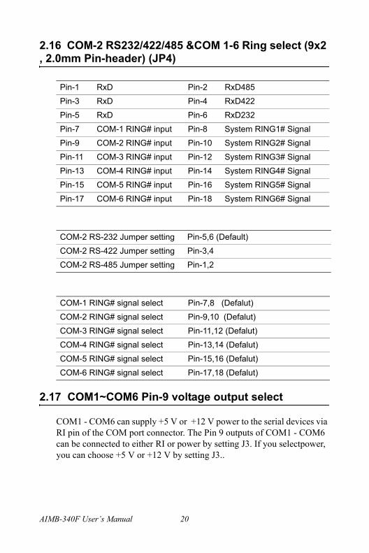
2.16 COM-2 RS232/422/485 &COM 1-6 Ring select (9x2 , 2.0mm Pin-header) (JP4)
2.17 COM1~COM6 Pin-9 voltage output select
COM1 - COM6 can supply +5 V or +12 V power to the serial devices via RI pin of the COM port connector. The Pin 9 outputs of COM1 - COM6 can be connected to either RI or power by setting J3. If you selectpower, you can choose +5 V or +12 V by setting J3..
Pin-1 RxD Pin-2 RxD485
Pin-3 RxD Pin-4 RxD422
Pin-5 RxD Pin-6 RxD232
Pin-7 COM-1 RING# input Pin-8 System RING1# Signal
Pin-9 COM-2 RING# input Pin-10 System RING2# Signal
Pin-11 COM-3 RING# input Pin-12 System RING3# Signal
Pin-13 COM-4 RING# input Pin-14 System RING4# Signal
Pin-15 COM-5 RING# input Pin-16 System RING5# Signal
Pin-17 COM-6 RING# input Pin-18 System RING6# Signal
COM-2 RS-232 Jumper setting Pin-5,6 (Default)
COM-2 RS-422 Jumper setting Pin-3,4
COM-2 RS-485 Jumper setting Pin-1,2
COM-1 RING# signal select Pin-7,8 (Defalut)
COM-2 RING# signal select Pin-9,10 (Defalut)
COM-3 RING# signal select Pin-11,12 (Defalut)
COM-4 RING# signal select Pin-13,14 (Defalut)
COM-5 RING# signal select Pin-15,16 (Defalut)
COM-6 RING# signal select Pin-17,18 (Defalut)
AIMB-340F User�s Manual 20

*** Default Non jumper ***
Examples: COM-1 Select +5V Output step => Change the JP4 Pin-7,8 jumper to JP3 Pin-1,3COM-1 Select +12V Output step => Change the JP4 Pin-7,8 jumper to JP3 Pin-3,5COM-2 Select +5V Output step => Change the JP4 Pin-9,10 jumper to JP3 Pin-2,4COM-2 Select +12V Output step => Change the JP4 Pin-9,10 jumper to JP3 Pin-4,6COM-3 Select +5V Output step => Change the JP4 Pin-11,12 jumper to JP3 Pin-9,11COM-3 Select +12V Output step => Change the JP4 Pin-11,12 jumper to JP3 Pin-11,13COM-4 Select +5V Output step => Change the JP4 Pin-13,14 jumper to JP3 Pin-10,12COM-4 Select +12V Output step => Change the JP4 Pin-13,14 jumper to JP3 Pin-12,14COM-5 Select +5V Output step => Change the JP4 Pin-15,16 jumper to JP3 Pin-17,19
Pin-1 +5V Pin-2 +5V
Pin-3 COM1-RI Pin-4 COM2-RI
Pin-5 +12V Pin-6 +12V
Pin-7 NC Pin-8 NC
Pin-9 +5V Pin-10 +5V
Pin-11 COM3-RI Pin-12 COM4-RI
Pin-13 +12V Pin-14 +12V
Pin-15 NC Pin-16 NC
Pin-17 +5V Pin-18 +5V
Pin-19 COM5-RI Pin-20 COM6-RI
Pin-21 +12V Pin-22 +12V
21 Chapter 2

COM-5 Select +12V Output step => Change the JP4 Pin-15,16 jumper to JP3 Pin-19,21COM-6 Select +5V Output step => Change the JP4 Pin-17,18 jumper to JP3 Pin-18,20COM-6 Select +12V Output step => Change the JP4 Pin-17,18 jumper to JP3 Pin-20,22
2.18 VGA interface connections
The AIMB-340F 's AGP 4X interface can drive conventional CRT dis-plays and is capable of driving a wide range of flat panel displays, includ-ing electroluminescent (EL), gas plasma, passive LCD and active LCD displays. The board has two connectors to support these displays, one for standard CRT VGA monitors and one for flat panel displays.
2.18.1 CRT display connector (CN1)CN1 is a standard 15-pin D-SUB connector commonly used for the CRT VGA monitor only. Pin assignments appear in the appendix.
2.18.2 Flat panel display connector (CN13)CN13 consists of a 40-pin header. It can connect to a 2 channel 48-bit LVDS LCD panel. Pin assignments appear in the appendix. (For more information on LCD connection information between CN13 and LCD, refer to Chapter 3.)
AIMB-340F User�s Manual 22

2.18.3 LCD VDDSAFE setting (JP2)The AIMB-340F's AGP 4X interface supports 5 V and 3.3 V LCD dis-plays. By changing the setting of JP2, you can select the panel video sig-nal level to be 5 V or 3.3 V.
Configuration of the VGA interface is done completely via the software utility. You do not have to set any jumpers. Refer to Chapter 3 for soft-ware setup details.
2.18.4 Inverter power connector (CN17)There is a 5pin connector (CN17) for inverter with +12V and +5V power connector.
2.19 Ethernet configuration
The AIMB-340F is equipped with a high performance 32-bit PCI-bus Ethernet interface which is fully compliant with IEEE 802.3 u10/100Mbps CSMA/CD standards. It is supported by all major network operating systems.It has an optional 10/100/1000Base-T Ethernet interface which is fully compliant with IEEE 802.3z/ab.
2.19.1 RJ-45 connector (CN9)100/10Base-T connects to the AIMB-340F via an RJ-45 standard jack.
2.19.2 Network bootThe Network Boot feature can be utilized by incorporating the Boot ROM image files for the appropriate network operating system. The Boot ROM BIOS files are on the included utility disk.
Table 2.3: LCD power (JP2)Closed pins Result
1-2 +5 V LCD panel
2-3 +3.3 V LCD panel*
23 Chapter 2

2.20 Watchdog timer configuration
An onboard watchdog timer reduces the chance of disruptions which EMP (electro-magnetic pulse) interference can cause. This is an invalu-able protective device for standalone or unmanned applications. Setup involves one jumper and running the control software (refer to Appendix A).When the watchdog timer activates (CPU processing has come to a halt), it can reset the system.
2.21 USB connector (CN7,CN9,CN16)
The AIMB-340F board provides six USB (Universal Serial Bus) inter-faces which support plug and play and hot attach/detach for up to 127 external devices. The USB interfaces comply with USB specification Rev. 2.0 support 480 Mbps transfer rate and are fuse protected.There are 4 USB2.0 jack on CN7 and CN9. And CN16 is for Embedde-dUSB Type I/II connection purpose.Embedded USB Interface is based on USB 2.0 and re-define pin assign-ment and connector type to fit Embedded MarketThe USB interfaces can be disabled in the system BIOS setup.
2.22 Digital I/O (CN19: 4 Outputs, 4 Inputs)
The POS-760 has two high drive digital outputs (24 VDC, 1 A max) and four digital inputs (TTL level). You can configure the digital I/O to con-trol the opening of the cash drawer and to sense the closing of the cash drawer. The following explains how the digital I/O is controlled via soft-ware programming and how a 12 V solenoid or relay can be triggered:
Digital I/O ConnectorIN0 1 2 +5 V
IN1 3 4 OUT0 (Max 1A)
IN2 5 6 GND
IN3 7 8 OUT1 (Max 1A)
GND 9 10 + 12 V
KEY 11 12 KEY
OUT3 13 14 GND
AIMB-340F User�s Manual 24

2.22.1 Digital output programmingOutput is CMOS MOSFET (high drive) type, capable of handling 24 VDC / 1 A loading. It is meant to drive relays or a solenoid.
Example: ("0" = off "1" = on)Data 00 = Out 0 and Out 1 = "0"Data 01 = Out 0 = "1"Data 02 = Out 1 = "1"Data 03 = Out 0 and Out 1 = "1"
2.23 IrDA Connector (CN21)
IrDA connector (CN21) shared with COM2. Transfer rates up to 1.15 Mbps
2.24 System LED (CN24)
There is a 14pin connector for system led. It included HDD,Power,Sus-pend,LAN ACT, ATX power and Reset LED. The more detail informa-tion can reference appendix.
2.25 Host bus speed select (JP1)
There is a 3pin connector (JP1) for host bus speed select.
OUT2 15 16 + 12
Table 2.4: Digital output programmingOutput Address Bit
Out 1 220 0
Out 2 220 1
Table 2.5: -> Host bus speed sel. Pin 1,2 short CPU select (default)
Pin2,3 short- 100 MHz
Prompt 133 MHz
Digital I/O Connector
25 Chapter 2

2.26 Watch Dog programer (CN15).
CN15 is reserved for watch dog programming purpose. The pin definita-tion reference appendix, please.
2.27 PCI slot expension (PCI1 or PCI2)
The location of PCI1 follow EmbeddedATX specification. And the loca-tion of PCI2 follow MicroATX 2nd PCI slot location. These two PCI slots can not function at the same time. It can have a riser card to expand the 2 PCI slots.
AIMB-340F User�s Manual 26

27 Chapter 3
CH
AP
TE
R 3Chipset Software Installation Utility
Chapter 3 Chipset Software Installation Utility
3.1 Before you begin
To facilitate the installation of the enhanced display device drivers and utility software, you should read the instructions in this chapter carefully before you attempt installation. The device drivers for the AIMB-340 board are located on the software installation CD. The auto-run function of the driver CD will guide and link you to the utilities and device drivers under a Windows system. The Intel® Chipset Software Installation Util-ity is not required on any systems running Windows NT 4.0. Updates are provided via Service Packs from Microsoft*.
Before you begin, it is important to note that most display drivers need to have the relevant software application already installed in the system prior to installing the enhanced display drivers. In addition, many of the installation procedures assume that you are familiar with both the rele-vant software applications and operating system commands. Review the relevant operating system commands and the pertinent sections of your application software�s user�s manual before performing the installation.
3.2 Introduction
The Intel® Chipset Software Installation (CSI) utility installs to the target system the Windows INF files that outline to the operating system how the chipset components will be configured. This is needed for the proper functioning of the following features:
� Core PCI and ISA PnP services.
� IDE Ultra ATA 100/66/33 interface support.
� USB 1.1 support (USB 2.0 driver needs to be installed separately)
� Identification of Intel ® chipset components in the Device Manager.
Note: The files on the software installation CD are compressed. Do not attempt to install the driv-ers by copying the files manually. You must use the supplied SETUP program to install the driv-ers.
AIMB-340 User�s Manual 28

� Integrates superior video features. These include filtered sealing of 720 pixel DVD content, and MPEG-2 motion compensation for soft-ware DVD
Windows 98SEWindows 2000Windows MeWindows XP
3.3 Installing the CSI Utility
1. Insert the driver CD into your system's CD-ROM drive. In a few seconds, the cd main menu appears. Move to "\\AIMB-340\Chipset\INF Driver\98_Me_2k_Xp INF V4.04.1007". And click "infinst_multi" icon..
Note: This utility is used for the following versions of Windows system, and it has to be installed before installing all the other drivers:
29 Chapter 3

2. Click "Next" when you see the following message.
3. Click "Yes" when you see the following message.
AIMB-340 User�s Manual 30

4. Click "Next" when you see the following message.
5. When the following message appears, click "Finish" to complete the installation and restart Windows.
31 Chapter 3

3.4 Connections for Standard LCDs
Table 3.1: LCD connectionsLG LM150x60 AIMB-340
Pin No. Function Pin No. Function
1 Vcc 1 VDDSAFE
2 Vcc 2 VDDSAFE
3 GND 3 GND
4 GND 4 GND
5 Rx0- 7 LVDS_0N
6 Rx0+ 9 LVDS_0P
7 GND 11 GND
8 Rx1- 13 LVDS_1N
9 Rx1+ 15 LVDS_1P
10 GND 17 GND
11 Rx2- 19 LVDS_2N
12 Rx2+ 21 LVDS_2P
13 GND 23 GND
14 RxC- 25 LVDS_C1N
15 RxC+ 27 LVDS_C1P
16 GND 29 GND
17 Rx3- 35 LVDS_3N
18 Rx3+ 37 LVDS_3P
19 GND 33 GND
20 NC
AIMB-340 User�s Manual 32

CHAPTER 4
Audio SetupThe AIMB-340F is equipped with an audio interface that records and plays back CD-quality audio. This chapter provides instructions for installing the software driversincluded on the audio driver diskettes.

Chapter 4 Audio Setup4.1 Introduction
The AIMB-340F' on-board audio interface provides high-quality stereo sound and FM music synthesis (ESFM) by using the Realtek ALC202 Audio Codec from Realtek. The audio interface can record, compress, and play back voice, sound, and music with built-in mixer control. The AIMB-340F�s on board audio interface also supports the Plug and Play (PnP) standard and provides PnP configuration for the audio, FM, and MPU-104 logical devices. It is compatible with Sound Blaster�; Sound Blaster Pro� version 3.01, voice and music functions. The ESFM synthesizer is register compatible with the OPL3 and has extended capa-bilities.
4.2 Driver installation
4.2.1 Before you beginPlease read the instructions in this chapter carefully before you attempt installation. The audio drivers for the AIMB-340F board are located on the audio driver CD. Run the supplied SETUP program to install the driv-ers; don�t copy the files manually.
4.2.2 Windows 9x/2000/Me/XP drivers
Note: 1. Note1: Before try to install driver, go to Chap-ter 3 to do "Chipset SoftwareInstallation Utility " first.2. The files on the software installation diskette are compressed. Do not attempt to install the drivers by copying the files manually. You must use the supplied SETUP program to install the drivers.
AIMB-340F User�s Manual 34

Step 1. Click "Start" and select "Settings". Click "Control Panel" and double-click Multimedia" icon and press " Reinstall Driver..." to do audio driver installation..
35 Chapter 4

Step 2. In the Hardware Update Wizard window, click "Next".
Step 3. In the following Hardware Update Wizard window, click "Fin-ish" for Windows to complete audio driver installation.
AIMB-340F User�s Manual 36

4.2.3 Windows NT driversStep 1. Click "Start" and select "Settings". Click "Control Panel" and
double-click "Multimedia".
Step 2. In the Multimedia Properties window, select the "Devices" tab. Then select the "Audio Devices" item, and click "Add...".
37 Chapter 4

Step 3. In the Add window, select the "Unlisted..." item and click "OK".
Step 4. When the Install Driver window appears, insert the utility disc into the CD-ROM drive. Type: D:\AIMB\340\Audio\WinNT\ Then click "OK".
D:\AIMB\340\Audio\WinNT\
AIMB-340F User�s Manual 38

Step 5. In the Add Unlisted or Updated Driver window, select the "Avance AC'97 Audio Driver" item. Then click "OK".
Step 6. In the System Setting Change window, click "Restart Now".
39 Chapter 4

AIMB-340F User�s Manual 40

41 Chapter 5
CH
AP
TE
R 5Award BIOS Setup

Chapter 5 Award BIOS Setup5.1 Introduction
Award�s BIOS ROM has a built-in setup program that allows users to modify the basic system configuration. This type of information is stored in battery-backed memory (CMOS RAM) so that it retains the setup information when the power is turned off.
5.1.1 CMOS RAM Auto-backup and RestoreThe CMOS RAM is powered by an onboard button cell battery. When you finish BIOS setup, the data in CMOS RAM will be automatically backed up to Flash ROM. If operation in harsh industrial enviroment cause a soft error, BIOS will recheck the data in CMOS RAM and auto-matically restore the original data in Flash ROM to CMOS RAM for booting.
Note: If you intend to change the CMOS setting with-out restoring the previous backup, you have to click on "DEL" within two seconds of the "CMOS checksum error..." display screen mes-sage appearing. Then enter the "Setup" screen to modify the data. If the "CMOS checksum error..."message appears again and again, please check to see if you need to replace the battery in your system.
AIMB-340F User�s Manual 42

5.2 Entering Setup
Turn on the computer and check for the �patch code�. If there is a number assigned to the patch code, it means that the BIOS supports your CPU.If there is no number assigned to the patch code, please contact Advan-tech�s applications engineer to obtain an up-to-date patch code file. This will ensure that your CPU�s system status is valid. After ensuring that you have a number assigned to the patch code, press <Del> to allow you to enter the setup.
Figure 5.1: Award BIOS Setup initial screen
43 Chapter 5
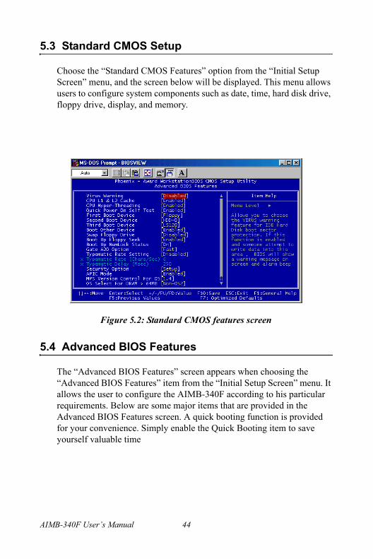
5.3 Standard CMOS Setup
Choose the �Standard CMOS Features� option from the �Initial Setup Screen� menu, and the screen below will be displayed. This menu allows users to configure system components such as date, time, hard disk drive, floppy drive, display, and memory.
5.4 Advanced BIOS Features
The �Advanced BIOS Features� screen appears when choosing the �Advanced BIOS Features� item from the �Initial Setup Screen� menu. It allows the user to configure the AIMB-340F according to his particular requirements. Below are some major items that are provided in the Advanced BIOS Features screen. A quick booting function is provided for your convenience. Simply enable the Quick Booting item to save yourself valuable time
Figure 5.2: Standard CMOS features screen
AIMB-340F User�s Manual 44

.
5.4.1 Virus WarningIf enabled, a warning message and alarm beep activates if someone attempts to write here. The commands are �Enabled� or �Disabled.�
5.4.2 L1 & L2 CacheEnabling this feature speeds up memory access. The commands are �Enabled� or �Disabled.�
5.4.3 Quick Power On Self TestThis option speeds up the Power-On Self Test (POST) conducted as soon as the computer is turned on. When enabled, BIOS shortens or skips some of the items during the test. When disabled, the computer conducts nor-mal POST procedures.
5.4.4 First/Second/Third/Other Boot Device The BIOS tries to load the OS with the devices in the sequence selected.Choices are: Floppy, LS/ZIP, HDD, SCSI, CDROM, LAN, Disabled.
5.4.5 Swap Floppy Drive Logical name assignments of floppy drives can be swapped if there is more than one floppy drive. The commands are �Enabled� or �Disabled.�
5.4.6 Boot UP Floppy Seek
Figure 5.3: Advanced BIOS features screen
45 Chapter 5
Selection of the command �Disabled� will speed the boot up. Selection of �Enabled� searches disk drives during boot up.
5.4.7 Boot Up NumLock Status This feature selects the �power on� state for NumLock. The commands are �Enabled� or �Disabled.�
5.4.8 Gate A20 OptionNormal: A pin in keyboard controller controls GateA20Fast (Default): Chipest controls GateA20.
5.4.9 Typematic Rate SettingThe typematic rate is the rate key strokes repeat as determined by the key-board controller. The commands are �Enabled� or �Disabled.� Enabling allows the typematic rate and delay to be selected.
5.4.10 Typematic Rate (Chars/Sec)BIOS accepts the following input values (characters/second) for type-matic rate: 6, 8, 10, 12, 15, 20, 24, 30.
5.4.11 Typematic Delay (msec)Typematic delay is the time interval between the appearance of two con-secutive characters, when holding down a key. The input values for this category are: 250, 500, 750, 1000 (msec).
5.4.12 Security OptionThis setting determines whether the system will boot up if the password is denied. Access to Setup is always limited.System The system will not boot, and access to Setup will be denied if the correct password is not entered at the prompt.Setup The system will boot, but access to Setup will be denied if the correct password is not entered at the prompt.
5.4.13 APIC ModeThis setting allows selecting an OS with greater than 64MB of RAM. Commands are �Non-OS2� or �OS2.�
Note: To disable security, select �PASSWORD SET-TING� in the main menu. At this point, you will be asked to enter a password. Simply press <Enter> to disable security. When security is disabled, the system will boot, and you can enter Setup freely.
AIMB-340F User�s Manual 46

5.4.14 MPS Version Control For OSThis reports if an FDD is available for Windows 95. The commands are �Yes� or �No.�
5.5 Integrated Peripherals
5.5.1 IDE Master/Slave PIO/UDMA Mode,IDE Primary (Secondary) Master/Slave PIO/UDMA Mode (Auto) Each channel (Primary and Secondary) has both a master and a slave, making four IDE devices possible. Because each IDE device may have a different Mode timing (0, 1, 2, 3, 4), it is necessary for these to be independent. The default setting �Auto� will allow autodetection to ensure optimal per-formance.
5.5.2 On-Chip Secondary PCI IDEIf you enable IDE HDD Block Mode, the enhanced IDE driver will be enabled. Leave IDE HDD Block Mode on the default setting.
Figure 5.4: Integrated peripherals
47 Chapter 5

5.5.3 USB ControllerSelect Enabled if your system contains a Universal Serial Bus (USB) con-troller and you have USB peripherals. The choices: Enabled, Disabled.
5.5.4 USB Keyboard/Mouse SupportSelect Enabled if user plan to use an USB keyboard. The choice: Enabled, Disable.
5.5.5 AC97 AudioSelect Disable if you do not want to use AC-97 audio. Option is Auto, Disable.
5.5.6 Init Display FirstThis item allows you to choose which one to activate first, PCI Slot or on-chip VGA. The choices: PCI Slot, Onboard.
5.5.7 Onboard LAN ControlOption is Enable and Disable. Select Disable if user does not want to use onboard LAN controller1
5.5.8 IDE HDD Block ModeYou can enable the Primary IDE channel and/or the Secondary IDE chan-nel. Any channel not enabled is disabled. This field is for systems with only SCSI drives.
5.5.9 Onboard FDC ControllerWhen enabled, this field allows you to connect your floppy disk drives to the onboard floppy disk drive connector instead of a separate controller card. If you want to use a different controller card to connect the floppy disk drives, set this field to Disabled.
5.5.10 Onboard Serial Port For settings reference the Appendix for the serial resource allocation,and Disabled for the on-board serial connector
5.5.11 UART Mode SelectThis item allows you to select UART mode. The choices: IrDA, ASKIR, Normal.
5.5.12 RxD, TxD ActiveThis item allows you to determine the active of RxD, TxD. The Choices: �Hi, Hi,� �Lo, Lo,� �Lo, Hi,� �Hi, Lo.�
5.5.13 IR Transmission DelayThis item allows you to enable/disable IR transmission delay. The choices: Enabled, Disabled.
AIMB-340F User�s Manual 48

5.5.14 UR2 Duplex ModeThis item allows you to select the IR half/full duplex funcion. The choices: Half, Full.
5.5.15 Onboard Parallel Port This field sets the address of the on-board parallel port connector. You can select either 3BCH/IRQ7, 378H/IRQ7, 278H/IRQ5 or Disabled. If you install an I/O card with a parallel port, make sure there is no conflict in the address assignments. The CPU card can support up to three parallel ports, as long as there are no conflicts for each port.
5.5.16 Parallel Port Mode This field allows you to set the operation mode of the parallel port. The setting �Normal� allows normal speed operation, but in one direction only. �EPP� allows bidirectional parallel port operation at maximum speed. �ECP� allows the parallel port to operate in bi-directional mode and at a speed faster than the maximum data transfer rate. �ECP + EPP� allows normal speed operation in a two-way mode.
5.5.17 EPP Mode SelectThis field allows you to select EPP port type 1.7 or 1.9. The choices:EPP1.7, 1.9.
5.5.18 ECP Mode Use DMAThis selection is available only if you select �ECP� or �ECP + EPP� in the Parallel Port Mode field. In ECP Mode Use DMA, you can select DMA channel 1, DMA channel 3, or Disable. Leave this field on the default setting.
49 Chapter 5

5.6 Power Management Setup
The power management setup controls the CPU card�s �green� features to save power. The following screen shows the manufacturer�s defaults::
5.6.1 Power-Supply Type Choose AT or ATX power supply
5.6.2 ACPI functionThe choice: Enabled, Disabled.
5.6.3 Power ManagementThis category allows you to select the type (or degree) of power saving and is directly related to the following modes:
1. HDD Power Down2. Suspend Mode
There are four selections for Power Management, three of which have fixed mode settings.
Figure 5.5: Power management setup screen
Min. Power Saving Minimum power management., Suspend Mode = 1 hr., and HDD Power Down = 15 min.
Max. Power Saving Maximum power management., Suspend Mode = 1 min., and HDD Power Down = 1 min.
AIMB-340F User�s Manual 50

5.6.4 Video Off In SuspendWhen system is in suspend, video will turn off.
5.6.5 Modem Use IRQThis determines the IRQ in which the MODEM can use.The choices: 3, 4, 5, 7, 9, 10, 11, NA.
5.6.6 HDD Power Down You can choose to turn the HDD off after one of the time intervals listed, or when the system is in �suspend� mode. If the HDD is in a power sav-ing mode, any access to it will wake it up.
5.6.7 Soft-Off by PWR-BTTNIf you choose �Instant-Off�, then pushing the ATX soft power switch but-ton once will switch the system to �system off� power mode. You can choose �Delay 4 sec.� If you do, then pushing the button for more than 4 seconds will turn off the system, whereas pushing the button momentarily (for less than 4 seconds) will switch the system to �suspend� mode.
5.6.8 CPU THRM-ThrottlingThis field allows you to select the CPU THRM-Throttling rate. The choices: 12.5%, 25.0%, 37.5%, 50.0%, 62.5%, 75.0%, 87.5%.
5.6.9 PowerOn By LANThis item allows you to wake up the system via LAN from the remote-host. The choices: Enabled, Disabled.
5.6.10 PowerOn By ModemWhen Enabled, an input signal on the serial Ring Indicator (RI) line (in other words, an incoming call on the modem) awakens the system from a soft off state. The choices: Enabled, Disabled.
5.6.11 PowerOn By AlarmWhen Enabled, your can set the date and time at which the RTC (real-time clock) alarm awakens the system from Suspend mode. The choices: Enabled, Disabled.
5.6.12 Primary IDE 0 (1) and Secondary IDE 0 (1)
User Defined (Default)
Allows you to set each mode individually. When not dis-abled, each of the ranges are from 1 min. to 1 hr. except for HDD Power Down which ranges from 1 min. to 15 min. and disable.
51 Chapter 5

When Enabled, the system will resume from suspend mode if Primary IDE 0 (1) or Secondary IDE 0 (1) is active. The choice: Enabled, Dis-abled.
5.6.13 FDD, COM, LPT PORTWhen Enabled, the system will resume from suspend mode if FDD, COM port, or LPT port is active. The choice: Enabled, Disabled.
5.6.14 PCI PIRQ [A-D]#When Enabled, the system will resume from suspend mode if interrupt occurs. The choice: Enabled, Disabled.
5.7 PnP/PCI Configurations
5.7.1 PnP OS InstalledSelect Yes if you are using a plug and play capable operating system. Select No if you need the BIOS to configure non-boot device
5.7.2 Reset Configuration DataDefault is Disable. Select Enable to reset Extended System Configura-tion Data (ESCD) if you have installed a new add-on and system econfig-uration has caused such a conflict that OS cannot boot.
5.7.3 Resources controlled by:
Figure 5.6: PnP/PCI configurations screen
AIMB-340F User�s Manual 52

The commands here are �Auto� or �Manual.� Choosing �manual� requires you to choose resources from each following sub-menu. �Auto� automatically configures all of the boot and Plug and Play devices but you must be using Windows 95 or above.
5.7.4 PCI/VGA Palette SnoopThis is left at �Disabled.�
5.8 PC Health Status
5.8.1 CPU Warning TemperatureThis item will prevent the CPU from overheating. The choices: 30~120.
5.8.2 Current CPU TemperatureThis shows you the current CPU temperature.
5.8.3 Current CPUFAN SpeedThis shows you the current CPUFAN operating speed.
5.8.4 +5V/+12V/-12V/-5V This shows you the voltage of +5V/+12V/-12V/-5V
Figure 5.7: PC health status screen
53 Chapter 5

5.9 Password Setting
To change the password:1. Choose the �Set Password� option from the �Initial Setup Screen� menu and press <Enter>.
The screen will display the following message:
Press <Enter>.2. If the CMOS is good or if this option has been used to change the default password, the user is asked for the password stored in the CMOS. The screen will display the following message:
Enter the current password and press <Enter>.3. After pressing <Enter> (ROM password) or the current password (user-defined), you can change the password stored in the CMOS. The password must be no longer than eight (8) characters.Remember, to enable the password setting feature, you must first select either �Setup� or �System� from the �Advanced BIOS Features� menu.
5.10 Save & Exit Setup
If you select this and press <Enter>, the values entered in the setup utili-ties will be recorded in the CMOS memory of the chipset. The micropro-cessor will check this every time you turn your system on and compare this to what it finds as it checks the system. This record is required for the system to operate.
Please Enter Your Password
Please Confirm Your Password
AIMB-340F User�s Manual 54

5.11 Exit Without Saving
Selecting this option and pressing <Enter> lets you exit the setup program without recording any new values or changing old ones.
55 Chapter 5

AIMB-340F User�s Manual 56

57 Chapter 6
CH
AP
TE
R 6VGA Setup
The AIMB-340F features an integrated VGA interface. This chapter provides instructions for installing the VGA drivers from the driver CD included in your package.

Chapter 6 VGA Setup6.1 Introduction
As quoted from "Intel® 845GV chipset Graphics Chipset Controller Hub (GMCH) Rev. 1.0 May 2002.�:The Intel® 845GV Graphics Memory Controller Hub (the 845GV GMCH) is Intel�s first memory controller hub with integrated graphics for the Intel Pentium® 4 processor. The 845GV GMCH, with its new architecture graphics engine, delivers not only high 2D/3D graphics per-formance, but also provides efficient, high bandwidth communication channels connecting the processor, the memory, the I/O subsystem, and other components together to deliver a stable mainstream desktop plat-form solution. The features include:� Built-in 2D/3D VGA controller.� Use Intel® Extreme Graphics Architecture� Integrated 350MHz RAMDAC that can directly drive a progressive
scan analog monitor up to a resolution of 2048 x 536 at 60 MHz� Up to 1600 x 1200 x 32 resolution at 85 Hz refresh.� H/W motion compensation assistance for s/w MPEG 2 decoding.� Software DVD at 30 fps Full Screen.
6.2 Dynamic Video Memory Technology
The following is quoted from "Intel® 845GV Chipset Dynamic Video Memory Technology" Rev. 1.2 June 2002�:Dynamic Video Memory Technology (DVMT) is an enhancement of the UMA concept, wherein the optimum amount of memory is allocated for balanced graphics and system performance, through Direct AGP known as Non-Local Video Memory (NLVM), and a highly efficient memory utilization scheme. DVMT ensures the most efficient use of available memory regardless of frame buffer or main memory sizing ñ for maxi-mum 2D/3D Graphics performance. DVMT dynamically responds to system requirements, and applications demands, by allocating the proper amount of display, texturing and buffer memory after the operating sys-tem has booted. For example, a 3D application when launched may require more vertex buffer memory to enhance the complexity of objects, or more texture memory to enhance the richness of the 3D environment.
AIMB-340F User�s Manual 58

The operating system views the integrated graphics driver as an applica-tion, which uses Direct AGP to request allocation of additional memory for 3D applications, and returns the memory to the operating system when no longer required. The Intel Extreme Graphics Driver determines the size of the pre-allo-cated memory needed and will make additional Non-Local Video Mem-ory requests to achieve the amount needed for the display and application requirement. The video memory size in the Intel® 845GV chipset varies and is determined using several factors. The key factors are system resources and system activity. The maximum video memory is up to 64MB SDRAM
6.3 Windows 9x/2000/Me/XP Installation
Note: Before installing this driver, make sure the CSI utility has been installed in your system. See Chapter 4 for information on installing the CSI utility
Note: Press �CRTL-Alt-F1� hotkey to enable CRT mode in Windows 98
59 Chapter 6

1. Insert the driver CD into your system's CD-ROM drive. In a fewseconds, the cd main menu appears. Move to "\\AIMB-340\VGA And click "win2k_xpm113" icon or "winnt4m113" icon. "win2k_xpm133" icon is for WIN9x, WIN2000, WINMe, WINXp and "winnt4m133" icon is for WINNT4.x operating system. installation procedure is for Windows 2000. For other operating systems, please follow the on-screen installa-tion guide
2. You will see a welcome window. Please chick on "Next" to con-tinue the installation.
AIMB-340F User�s Manual 60
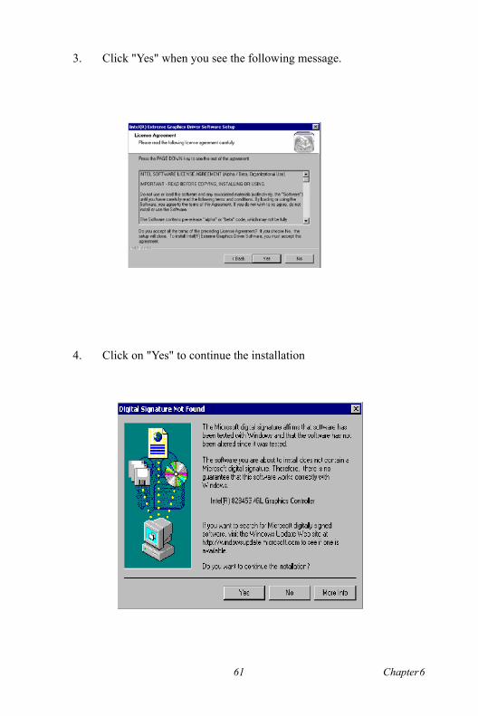
3. Click "Yes" when you see the following message.
4. Click on "Yes" to continue the installation
61 Chapter 6

5. VGA driver is now installing
6. When the following message appears, you can choose to restart the computer now or later.
AIMB-340F User�s Manual 62

6.3.1 Installation for Windows NT
1. Select "Start", "Settings", "Control Panel" and double click the "Display" icon.
Note: Service Pack X (X = 3, 4, 5, 6,...) must be installed first, before you install the Windows NT VGA driver.
63 Chapter 6

2. Choose the "Settings" tab, and press the "Display Type" button.
AIMB-340F User�s Manual 64

3. Press the "Change..." button.
4. Click the "OK..." button.
65 Chapter 6

5. Click "Next" to go next step.
6. Click "Next" button.
AIMB-340F User�s Manual 66

7. Press "Yes" to proceed.
8. Press "Yes" to reboot.
67 Chapter 6

AIMB-340F User�s Manual 68

69 Chapter 7
CH
AP
TE
R 7LAN Configuration
� Introduction� Features� Installation of Ethernet Driver for
- Windows 2000 Drivers Setup Steps- Windows NT Drivers Setup Steps-Windows Wake-on-LAN Setup

Chapter 7 PCI Bus Ethernet Interface7.1 Introduction
The AIMB-340F is equipped with a high-performance 32-bit Ethernet chipset which is fully compliant with IEEE 802.3 100 Mbps CSMA/CD standards. It is supported by major network operating systems. It is also both 100Base-T and 10Base-T compatible.
7.2 Features
� Intel 82562/82551 10/100Base-T Ethernet LAN controller� Optional Intel 82540 10/100/1000 Base-T Ethernet LAN controller� Supports Wake-on-LAN remote control function.� PCI Bus Master complies with PCI Rev. 2.2� Complies with 100Base-TX, and 10Base-T applications.� Single RJ-45 connector gives auto-detection of 10 Mbps or 100 Mbps
network data transfer rates and connected cable types.� Enhancements on ACPI & APM.� Complies with PCI Bus Power Management Interface Rev. 1.1,� ACPI Rev. 2.0, and Device Class Power Management Rev. 1.0.
7.3 Installation of Ethernet Driver
Before installing the Ethernet driver, note the procedures below. You must know which operating system you are using in your AIMB-340F, and then refer to the corresponding installation procedure. Then just fol-low the steps described. You will quickly and successfully complete the installation, even if you are not familiar with instructions for Windows..
Note: The windows illustrations in this chapter are examples only. You must follow the flow chart instructions and pay attention to the instructions which then appear on your screen.
AIMB-340F User�s Manual 70

7.3.1 Installation for Windows 2000
1. Click "Setup" icon in path "D:\AIMB\340\LAN\"
Note: The CD-ROM drive is designated as"D" throughout this section.
71 Chapter 7

2. Choose "Modify" item and click "Next" to go next step.
3. Highlight "Drivers for wired Ethernet adapters" and click "Next".
AIMB-340F User�s Manual 72

4. Click "Install" to begin the installation.
5. Click "Finish" to exit the wizard.
73 Chapter 7

6. Then the Installer will show the result after driver installed.
AIMB-340F User�s Manual 74

7.3.2 Installation for Windows NT 1. Select "Start", "Settings", "Control Panel" and double click "Network" icon.
2. Then this menu will show on the screen. And click "Yes" to install net-work driver.
75 Chapter 7

3. Select "Wired to the network" and click "Next"
4. Click "Start Search" to searh a Network Adapter. Then click "Next" to go next step
AIMB-340F User�s Manual 76

5. Base on current network environment to modify the Network Protocol then Click "Next"
77 Chapter 7

6.Click "Next" to go to next step
7. Click "Next" to install Network Adapter driver.
AIMB-340F User�s Manual 78

8. Check the Licemse Agreement first then select "I accept the terms in the license agreement" and click "Next".
9. Select "Typical" and Click "Next".
79 Chapter 7
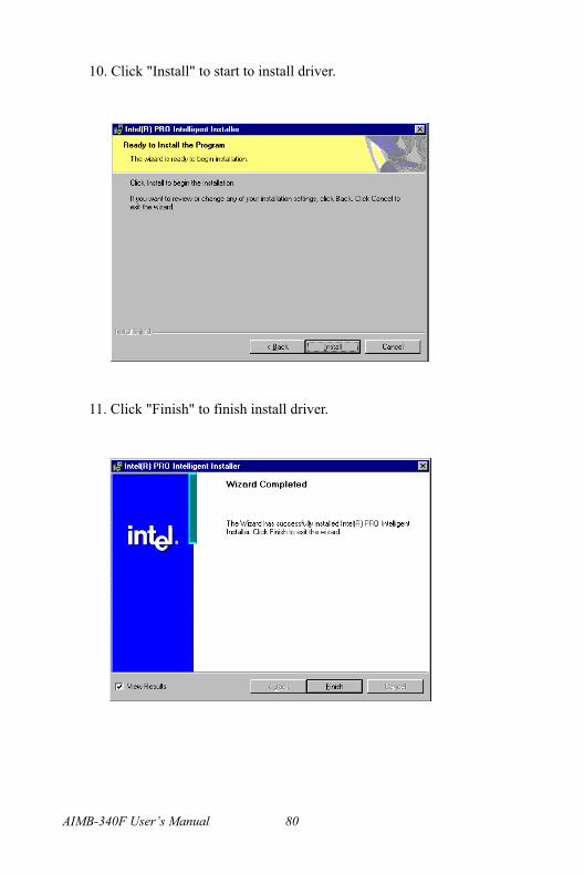
10. Click "Install" to start to install driver.
11. Click "Finish" to finish install driver.
AIMB-340F User�s Manual 80

7.4 Further information
Realtek website: www.realtek.comAdvantech websites:www.advantech.com
www.advantech.com.tw
81 Chapter 7

AIMB-340F User�s Manual 82

Appendix A
Programming the Watchdog Timer
The AIMB-340F is equipped with a watchdog timer that resets the CPU or generates an interrupt if processing comes to a standstill for whatever rea-son. This feature ensures system reli-ability in industrial standalone or unmanned environments.

Appendix A Programming the Watchdog Timer
A.1 Programming the watchdog timer
The following example shows how you might program the watchdog timer in assembly:Watch Dog:;-----------------------------------------------------------------------------------; Enter the extended function mode ,interruptible double-write |;-----------------------------------------------------------------------------------MOV DX,2EHMOV AL,87HOUT DX,ALOUT DX,AL;-----------------------------------------------------------------------------; Configurate logical device 8, configuration register CRF6 |;-----------------------------------------------------------------------------MOV DX,2EH MOV AL,07H ; point to Logical Device Number Reg.OUT DX,AL MOV DX,2FHMOV AL,08H ; select logical device 8OUT DX,AL ;MOV DX,2EH MOV AL,30H ;Set watch dog activate or inactivateOUT DX,AL MOV DX,2FHMOV AL,01H ; 01:activate 00:inactivateOUT DX,AL ;
AIMB-340F User�s Manual 84

MOV DX,2EH MOV AL,F5H ; Setting counter unit is secondOUT DX,AL MOV DX,2FHMOV AL,00HOUT DX,AL;MOV DX,2EH MOV AL,F6HOUT DX,ALMOV DX,2FHMOV AL,05H ; Set 5 secondsOUT DX,AL
;------------------------------------------; Exit extended function mode |;------------------------------------------MOV DX,2EHMOV AL,AAHOUT DX,AL
85 Appendix A

AIMB-340F User�s Manual 86

Appendix B
Sample Code of GPIO programming

Appendix B Sample Code of GPIO pro-gramming
GPIO output ;-----------------------------------------------------------------------------------; Enter the extended function mode ,interruptible double-write |;-----------------------------------------------------------------------------------MOV DX,2EHMOV AL,87HOUT DX,ALOUT DX,AL;--------------------------------------------------------------------------------------------------------------; Configurate logical device 7(GP10~GP17), configuration register CRF0,CRF1,CRF2 |;--------------------------------------------------------------------------------------------------------------MOV DX,2EH MOV AL,07H ; point to Logical Device Number Reg.OUT DX,AL MOV DX,2FHMOV AL,07H ; select logical device 7OUT DX,AL ;MOV DX,2EH MOV AL,F0 OUT DX,AL MOV DX,2FHMOV AL,00H ; 01:Input 00:output for GP10~GP17OUT DX,AL ;MOV DX,2EH MOV AL,F2H ;
AIMB-340F User�s Manual 88

OUT DX,AL MOV DX,2FHMOV AL,00H ;Set GPIO is normal not inverterOUT DX,AL;MOV DX,2EH MOV AL,F1HOUT DX,ALMOV DX,2FHMOV AL,??H ; Put the output value into AL OUT DX,AL ;------------------------------------------; Exit extended function mode |;------------------------------------------MOV DX,2EHMOV AL,AAHOUT DX,AL
89 Appendix B

AIMB-340F User�s Manual 90

Appendix C
Connector Definition and Jumper Settings
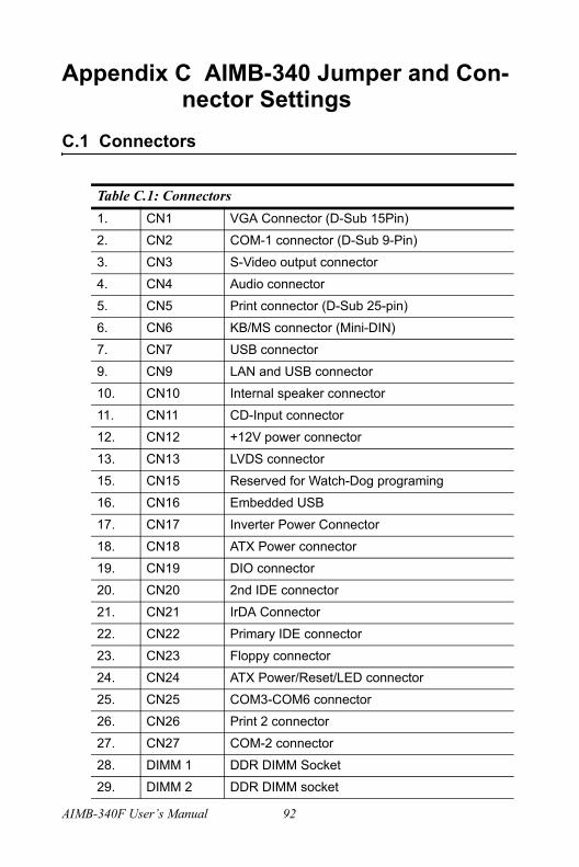
Appendix C AIMB-340 Jumper and Con-nector Settings
C.1 Connectors
Table C.1: Connectors1. CN1 VGA Connector (D-Sub 15Pin)
2. CN2 COM-1 connector (D-Sub 9-Pin)
3. CN3 S-Video output connector
4. CN4 Audio connector
5. CN5 Print connector (D-Sub 25-pin)
6. CN6 KB/MS connector (Mini-DIN)
7. CN7 USB connector
9. CN9 LAN and USB connector
10. CN10 Internal speaker connector
11. CN11 CD-Input connector
12. CN12 +12V power connector
13. CN13 LVDS connector
15. CN15 Reserved for Watch-Dog programing
16. CN16 Embedded USB
17. CN17 Inverter Power Connector
18. CN18 ATX Power connector
19. CN19 DIO connector
20. CN20 2nd IDE connector
21. CN21 IrDA Connector
22. CN22 Primary IDE connector
23. CN23 Floppy connector
24. CN24 ATX Power/Reset/LED connector
25. CN25 COM3-COM6 connector
26. CN26 Print 2 connector
27. CN27 COM-2 connector
28. DIMM 1 DDR DIMM Socket
29. DIMM 2 DDR DIMM socket
AIMB-340F User�s Manual 92

C.2 CN1 VGA D-TYPE 15 Pins connector
C.3 CN2 COM1 D-TYPE 9 Pins connect
30. FAN 1 CPU FAN
31. FAN2 System FAN
32. PCI1 PCI Slot-1
33. PCI2 PCI Slot-2 (optional)
34. SL1 AGP Slot (optional)
35. SW2 Clear CMOS switch
pin signal pin signal
1 R 9 NC
2 G 10 GND
3 B 11 NC
4 NC 12 SMB DATA
5 GND 13 HSYNC
6 GND 14 VSYNC
7 GND 15 SMB CLK
8 GND
pin signal pin signal
1 DCD 2 RX
3 TX 4 DTR
5 GND 6 DSR
7 RTS 8 CTS
9 RI & POWER
Table C.1: Connectors
93 Appendix C

C.4 CN3 S-Video output (4 Pin 2.0mm wafer box)
C.5 CN4 Audio connector
C.6 CN25 LPT1 D-TYPE 25 Pin connector
pin signalpin 1 Y
pin 2 GND
pin 3 GND
pin 4 C
Pink MIC input
Lime Line out
Blue Line in
pin signal pin signal
1 STB 14 AFD
2 PD0 15 ERR
3 PD1 16 INIT
4 PD2 17 SLIN
5 PD3 18 GND
6 PD4 19 GND
7 PD5 20 GND
8 PD6 21 GND
9 PD7 22 GND
10 ACK 23 GND
11 BUSY 24 GND
12 PE 25 GND
13 SLCT
AIMB-340F User�s Manual 94

C.7 CN26 USB2.0 1 & 2 connect
C.8 CN8 Internal speaker(4x1,2.0mm Wafer-box)
C.9 CN11 CD-Input connector (4x1,2.54 mm Wafer-box)
pin signal pin signal
1 VCC 2 VCC
3 DAT1- 4 DAT2-
5 DAT1+ 6 DAT2+
7 GND 8 GND
9 GND 10 GND
pin signalPin-1 Speaker_L-
Pin-2 Speaker_L+
Pin-3 Speaker_R+
Pin-4 Speaker_R-
pin signalPin-1 CDIN_R
Pin-2 CD_GND
Pin-3 CD_GND
Pin-4 CDIN_L
95 Appendix C

C.10 CN12 +12V Power connector (2x2)
pin signalPin-1 GND
Pin-2 GND
Pin-3 +12V
Pin-4 +12V
AIMB-340F User�s Manual 96

C.11 CN13 LVDS (20x2,DF13 connector)
pin signal pin signalPin-1 VDDSAFE (Select by
JP2)Pin-2 VDDSAFE (Select
by JP2)
Pin-3 => GND Pin-4 GND
Pin-5 VDDSAFE (Select by JP2)
Pin-6 VDDSAFE (Select by JP2)
Pin-7 LVDS_0N Pin-8 LVDS_4N
Pin-9 LVDS_0P Pin-10 LVDS_4P
Pin-11 GND Pin-12 GND
Pin-13 LVDS_1N Pin-14 LVDS_5N
Pin-15 LVDS_1P Pin-16 LVDS_5P
Pin-17 GND Pin-18 GND
Pin-19 LVDS_2N Pin-20 LVDS_6N
Pin-21 LVDS_2P Pin-22 LVDS_6P
Pin-23 GND Pin-24 GND
Pin-25 LVDS_C1N Pin-26 LVDS_C2N
Pin-27 LVDS_C1P Pin-28 LVDS_C2P
Pin-29 GND Pin-30 GND
Pin-31 DDC_CLK Pin-32 DDC_DATA
Pin-33 GND Pin-34 GND
Pin-35 LVDS_C3N Pin-36 LVDS_C7N
Pin-37 LVDS_C3P Pin-38 LVDS_C7P
Pin-39 HPLG_DTS Pin-40 VCON
97 Appendix C

C.12 CN15 Reserved to program the Watch-dog
C.13 CN16 Embedded USB (9x2,2.54 mm Pin-header)
pin signalPin-1 +3.3V
Pin-2 GND
Pin-3 TDI
Pin-4 TMS
Pin-5 TCK
Pin-6 TDO
pin signal pin signalPin-1 GND Pin-2 GND
Pin-3 GND Pin-4 GND
Pin-5 +5V Pin-6 +5V
Pin-7 USB4_D- Pin-8 USB5_D-
Pin-9 USB4_D+ Pin-10 USB5_D+
Pin-11 GND Pin-12 GND
Pin-13 Key Pin-14t Over Current# Output
Pin-15 +5V Pin-16 +3.3V
Pin-17 GND Pin-18 GND
Pin-9 NC Pin-10 GND
AIMB-340F User�s Manual 98
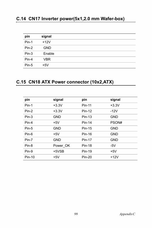
C.14 CN17 Inverter power(5x1,2.0 mm Wafer-box)
C.15 CN18 ATX Power connector (10x2,ATX)
pin signalPin-1 +12V
Pin-2 GND
Pin-3 Enable
Pin-4 VBR
Pin-5 +5V
pin signal pin signalPin-1 +3.3V Pin-11 +3.3V
Pin-2 +3.3V Pin-12 -12V
Pin-3 GND Pin-13 GND
Pin-4 +5V Pin-14 PSON#
Pin-5 GND Pin-15 GND
Pin-6 +5V Pin-16 GND
Pin-7 GND Pin-17 GND
Pin-8 Power_OK Pin-18 -5V
Pin-9 +5VSB Pin-19 +5V
Pin-10 +5V Pin-20 +12V
99 Appendix C
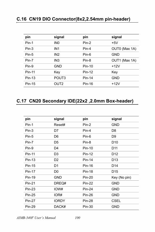
C.16 CN19 DIO Connector(8x2,2.54mm pin-header)
C.17 CN20 Secondary IDE(22x2 ,2.0mm Box-header)
pin signal pin signalPin-1 IN0 Pin-2 +5V
Pin-3 IN1 Pin-4 OUT0 (Max 1A)
Pin-5 IN2 Pin-6 GND
Pin-7 IN3 Pin-8 OUT1 (Max 1A)
Pin-9 GND Pin-10 +12V
Pin-11 Key Pin-12 Key
Pin-13 POUT3 Pin-14 GND
Pin-15 OUT2 Pin-16 +12V
pin signal pin signalPin-1 Reset# Pin-2 GND
Pin-3 D7 Pin-4 D8
Pin-5 D6 Pin-6 D9
Pin-7 D5 Pin-8 D10
Pin-9 D4 Pin-10 D11
Pin-11 D3 Pin-12 D12
Pin-13 D2 Pin-14 D13
Pin-15 D1 Pin-16 D14
Pin-17 D0 Pin-18 D15
Pin-19 GND Pin-20 Key (No pin)
Pin-21 DREQ# Pin-22 GND
Pin-23 IOW# Pin-24 GND
Pin-25 IOR# Pin-26 GND
Pin-27 IORDY Pin-28 CSEL
Pin-29 DACK# Pin-30 GND
AIMB-340F User�s Manual 100

C.18 CN21 IrDA Connector(5x1,2.54mm Pin-header)
Pin-31 IRQ Pin-32 NC
Pin-33 A1 Pin-34 P66 Detect
Pin-35 A0 Pin-36 A2
Pin-37 CS0# Pin-38 CS1#
Pin-39 HDD-LED# Pin-40 GND
Pin-41 +5V Pin-42 +5V
Pin-43 GND Pin-44 NC
pin signalPin-1 +5V
Pin-2 CIRRX
Pin-3 IRRX
Pin-4 GND
Pin-5 IRTX
101 Appendix C

C.19 CN22 Primary IDE(20x2 , 2.54mm Box-header)
pin signal pin signalPin-1 Reset# Pin-2 GND
Pin-3 D7 Pin-4 D8
Pin-5 D6 Pin-6 D9
Pin-7 D5 Pin-8 D10
Pin-9 D4 Pin-10 D11
Pin-11 D3 Pin-12 D12
Pin-13 D2 Pin-14 D13
Pin-15 D1 Pin-16 D14
Pin-17 D0 Pin-18 D15
Pin-19 GND Pin-20 Key (No pin)
Pin-21 DREQ# Pin-22 GND
Pin-23 IOW# Pin-24 GND
Pin-25 IOR# Pin-26 GND
Pin-27 IORDY Pin-28 CSEL
Pin-29 DACK# Pin-30 GND
Pin-31 IRQ Pin-32 NC
Pin-33 A1 Pin-34 P66 Detect
Pin-35 A0 Pin-36 A2
Pin-37 CS0# Pin-38 CS1#
Pin-39 HDD-LED# Pin-40 GND
AIMB-340F User�s Manual 102

C.20 CN23 Floppy(26 Pin FDC connector)(optional)
pin signalPin-1 VCC
Pin-2 INDEX#
Pin-3 VCC
Pin-4 DSA#
Pin-5 VCC
Pin-6 DSKCHG#
Pin-7 NC
Pin-8 NC
Pin-9 NC
Pin-10 MOA#
Pin-11 NC
Pin-12 DIR#
Pin-13 NC
Pin-14 STEP#
Pin-15 GND
Pin-16 WD#
Pin-17 GND
Pin-18 WE#
Pin-19 GND
Pin-20 TRACK0#
Pin-21 GND
Pin-22 WP#
Pin-23 GND
Pin-24 RDATA#
Pin-25 GND
Pin-26 HEAD#
103 Appendix C

C.21 CN24 ATX pwr/Reset/LED (7x2 , 2.54mm Pin-header)
C.22 CN25 COM3 - COM6(20x2 , 2.0 mm Box-header)
pin signal pin signalPin-1 HDD_LED+ Pin-2 HDD_LED-
Pin-3 Power_LED+ Pin-4 Power_LED-
Pin-5 Suspend_LED+ Pin-6 Suspend_LED-
Pin-7 LAN1_ACTLED+ Pin-8 LAN1_ACTLED-
Pin-9 NC Pin-10 NC
Pin-11 ATX_PWR_SW Pin-12 ATX_PWR_SW
Pin-13 Reset_SW Pin-14 Reset_SW
pin signal pin signalPin-1 COM3 DCD Pin-2 COM3 DSR
Pin-3 COM3 RxD Pin-4 COM3 RTS
Pin-5 COM3 TxD Pin-6 COM3 CTS
Pin-7 PCOM3 DTR Pin-8 COM3 RI
Pin-9 GND Pin-10 GND
Pin-11 COM4 DCD Pin-12 COM4 DSR
Pin-13 COM4 RxD Pin-14 COM4 RTS
Pin-15 COM4 TxD Pin-16 COM4 CTS
Pin-17 COM4 DTR Pin-18 COM4 RI
Pin-19 GND Pin-20 GND
Pin-21 COM5 DCD Pin-22 COM5 DSR
Pin-23 COM5 RxD Pin-24 COM5 RTS
Pin-25 COM5 TxD Pin-26 COM5 CTS
Pin-27 COM5 DTR Pin-28 COM5 RI
Pin-29 GND Pin-30 GND
Pin-31 COM6 DCD Pin-32 COM6 DSR
Pin-33 COM6 RxD Pin-34 COM6 RTS
Pin-35 COM6 TxD Pin-36 COM6 CTS
Pin-37 COM6 DTR Pin-38 COM6 RI
Pin-39 GND Pin-40 GND
AIMB-340F User�s Manual 104

C.23 CN26 PRN2(13x2,2.0 mm Box-header)
C.24 CN27 COM-2(7x2,2.0mm Box-header)
pin signal pin signalPin-1 STB# Pin-2 P AFD#
Pin-3 D0 Pin-4 ERR#
Pin-5 D1 Pin-6 INIT#
Pin-7 D2 Pin-8 SLIN
Pin-9 D3 Pin-10 GND
Pin-11 D4 Pin-12 GND
Pin-13 D5 Pin-14 GND
Pin-15 D6 Pin-16 GND
Pin-17 D7 Pin-18 GND
Pin-19 ACK# Pin-20 GND
Pin-21 BUSY Pin-22 GND
Pin-23 PE Pin-24 GND
Pin-25 SLCT Pin-26 NC
pin signal pin signalPin-1 DCD Pin-2 DSR
Pin-3 RxD Pin-4 RTS
Pin-5 TxD Pin-6 CTS
Pin-7 DTR Pin-8 RI
Pin-9 GND Pin-10 PGND
Pin-11 422/485 TxD+ Pin-12 422/485 TxD-
Pin-13 422 RxD+ Pin-14 422 RxD-
105 Appendix C
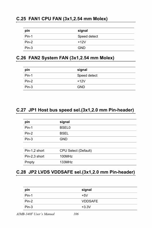
C.25 FAN1 CPU FAN (3x1,2.54 mm Molex)
C.26 FAN2 System FAN (3x1,2.54 mm Molex)
C.27 JP1 Host bus speed sel.(3x1,2.0 mm Pin-header)
C.28 JP2 LVDS VDDSAFE sel.(3x1,2.0 mm Pin-header)
pin signalPin-1 Speed detect
Pin-2 +12V
Pin-3 GND
pin signalPin-1 Speed detect
Pin-2 +12V
Pin-3 GND
pin signalPin-1 BSEL0
Pin-2 BSEL
Pin-3 GND
Pin-1,2 short CPU Select (Default)
Pin-2,3 short 100MHz
Pmpty 133MHz
pin signalPin-1 +5V
Pin-2 VDDSAFE
Pin-3 +3.3V
AIMB-340F User�s Manual 106

Default Pin-2,3 short
C.29 JP3 COM1-6 Pin-9 V out (11x2,2.0mm Pin-header)
*** Default Non jumper ***
Examples: COM-1 Select +5V Output step => Change the JP4 Pin-7,8 jumper to JP3 Pin-1,3COM-1 Select +12V Output step => Change the JP4 Pin-7,8 jumper to JP3 Pin-3,5COM-2 Select +5V Output step => Change the JP4 Pin-9,10 jumper to JP3 Pin-2,4COM-2 Select +12V Output step => Change the JP4 Pin-9,10 jumper to JP3 Pin-4,6COM-3 Select +5V Output step => Change the JP4 Pin-11,12 jumper to JP3 Pin-9,11COM-3 Select +12V Output step => Change the JP4 Pin-11,12 jumper to JP3 Pin-11,13COM-4 Select +5V Output step => Change the JP4 Pin-13,14 jumper to JP3 Pin-10,12
pin signal pin signalPin-1 +5V Pin-2 +5V
Pin-3 COM1-RI Pin-4 COM2-RI
Pin-5 +12V Pin-6 +12V
Pin-7 NC Pin-8 NC
Pin-9 +5V Pin-10 +5V
Pin-11 COM3-RI Pin-12 COM4-RI
Pin-13 +12V Pin-14 +12V
Pin-15 NC Pin-16 NC
Pin-17 +5V Pin-18 +5V
Pin-19 COM5-RI Pin-20 COM6-RI
Pin-21 +12V Pin-22 +12V
107 Appendix C

COM-4 Select +12V Output step => Change the JP4 Pin-13,14 jumper to JP3 Pin-12,14COM-5 Select +5V Output step => Change the JP4 Pin-15,16 jumper to JP3 Pin-17,19COM-5 Select +12V Output step => Change the JP4 Pin-15,16 jumper to JP3 Pin-19,21COM-6 Select +5V Output step => Change the JP4 Pin-17,18 jumper to JP3 Pin-18,20COM-6 Select +12V Output step => Change the JP4 Pin-17,18 jumper to JP3 Pin-20,22
C.30 JP4 COM-2 RS232/422/485 and COM-1 to COM-6 Ring signal select (9x2 , 2.0mm Pin-header)
pin signal pin signalPin-1 RxD Pin-2 RxD485
Pin-3 RxD Pin-4 RxD422
Pin-5 RxD Pin-6 RxD232
Pin-7 COM-1 RING# input Pin-8 System RING1# Signal
Pin-9 COM-2 RING# input Pin-10 System RING2# Signal
Pin-11 COM-3 RING# input Pin-12 System RING3# Signal
Pin-13 COM-4 RING# input Pin-14 System RING4# Signal
Pin-15 COM-5 RING# input Pin-16 System RING5# Signal
Pin-17 COM-6 RING# input Pin-18 System RING6# Signal
COM-2 RS-232 Jumper setting Pin-5,6 (Default)
COM-2 RS-422 Jumper setting Pin-3,4
COM-2 RS-485 Jumper setting Pin-1,2
COM-1 RING# signal select Pin-7,8 (Defalut)
COM-2 RING# signal select Pin-9,10 (Defalut)
COM-3 RING# signal select Pin-11,12 (Defalut)
AIMB-340F User�s Manual 108

COM-4 RING# signal select Pin-13,14 (Defalut)
COM-5 RING# signal select Pin-15,16 (Defalut)
COM-6 RING# signal select Pin-17,18 (Defalut)
109 Appendix C

AIMB-340F User�s Manual 110

Ap
pe
nd
ix DIRQ Resource Table

Appendix D IRQ ResourcesD.1 IRQ Resource Guide
IRQ 0 : Timer
IRQ 1: Keyboard
IRQ 2: Bridge
IRQ 3: COM2
IRQ 4: COM1
IRQ 5: COM3~COM6 share or Printer 2
IRQ6: FDD
IRQ7: Printer 1
IRQ8: IRTC
IRQ9: ACPI
IRQ10: ICOM 3~COM6 share
IRQ11: LAN
IRQ12: PS2/Mouse
IRQ13: Core Processor
IRQ14: IDE
IRQ 15: IDE (CD_ROM)
AIMB-340F User�s Manual 112

113 Appendix D

AIMB-340F User�s Manual 114
Related Documents


