Welcome message from author
This document is posted to help you gain knowledge. Please leave a comment to let me know what you think about it! Share it to your friends and learn new things together.
Transcript
Page 2 of 26
Table of contents Table of contents................................................................................................................. 2
Lewatit® MonoPlus S 108 (H)............................................................................................. 3 General information ......................................................................................................................3
1. Recommended operating conditions.......................................................................... 4
2. Operating capacity of Lewatit® MonoPlus S 108........................................................ 5 2.1 Co-current operation (HCl regeneration) .............................................................................5 2.2 Average sodium leakage in co-flow operation (regeneration with HCl) ...............................7 2.3 Co-current operation (H2SO4 regeneration).........................................................................8 2.4 Average sodium leakage in co-flow operation (regeneration with H2SO4).........................10
3. Operating capacity of Lewatit® MonoPlus S 108..................................................... 11 3.1 Counter-current operation (HCl regeneration)...................................................................11 3.2 Counter-current operation (H2SO4 regeneration) .............................................................14
3.2.1 Permitted H2SO4 concentration (progressive) .........................................................16
4. Osmotic stability of Lewatit® MonoPlus S 108 (H) .................................................. 17 4.1 Osmotic shock test ............................................................................................................17
5. Leachables .................................................................................................................. 19 5.1 Leachables test method ....................................................................................................19
6. Hydraulic characteristics ........................................................................................... 20 6.1 Bed expansion...................................................................................................................20 6.2 Pressure drop data ............................................................................................................21
7. Mixed bed combination .............................................................................................. 22 7.1 Mixed bed resin combination.............................................................................................23
8. Epilogue....................................................................................................................... 25 Disclaimer ...................................................................................................................................26
Page 3 of 26
LEWATIT® MONOPLUS S 108 (H) GENERAL INFORMATION
Lewatit® MonoPlus S 108 is a new strongly
acidic, gel-type cation exchange resin in the Na-form with beads of uniform size (monodisperse) based on a styrene-divinylbenzene copolymer. Due to a special manufacturing process this resin type is extremely resistant to chemical, osmotic and mechanical stress (see chapter 4). That leads to very low leachables even under critical conditions like higher temperatures, presence of oxidants (O2, Fe-oxides) and external regeneration processes (see chapter 5). Even at very short cycle times (one cycle = service + regeneration) the special ion exchange resin matrix leads to long life cycles in demineralization processes.
The improved total capacity results in high
operating capacities with a very low ionic leakage and very low regenerant consumption (see diagrams 1,5,7,11).
The extremely high monodispersity (uniformity
coefficient: max. 1.05) and very low fines content of max. 0.1 % (< 0.4 mm) results in particularly low pressure losses paired with an efficient and cost optimized operation of demineralization plants.
Lewatit® MonoPlus S 108 complies with FDA
regulation CFR 21 173.25 and is also available in the hydrogen form (Lewatit® MonoPlus S 108 H).
Lewatit® MonoPlus S 108 (H) is especially
suitable for
• demineralization of water for industrial steam generation operated with co-current or modern counter-current systems like e.g. Lewatit® WS System, Lewatit® Liftbed System or Lewatit® Rinsebed System
• polishing using the Lewatit® Multistep System or a conventional mixed bed arrangement in combination with Lewatit® MonoPlus M 500 MB or Lewatit® MonoPlus M 800 (OH).
Lewatit® MonoPlus S 108 (H) adds special
features to the resin bed:
• high flow rates during regeneration and loading • high operating capacity at low regenerant
consumption • low rinse water requirement • homogeneous throughput of regenerants,
water and solutions, resulting in a homogeneous operating zone
• virtually linear pressure drop gradient across the entire bed depth, allowing operation with higher bed depths
• low TOC emission and high resistance to oxidative stress
• good separation of the components in mixed bed applications. This technical information relates to the
demineralization of water using HCl or H2SO4 as the regenerant in co-current or counter-current operation. The data provided here allow calculation of the operating capacity and sodium leakage under various conditions (process, feed water conditions, operating conditions).
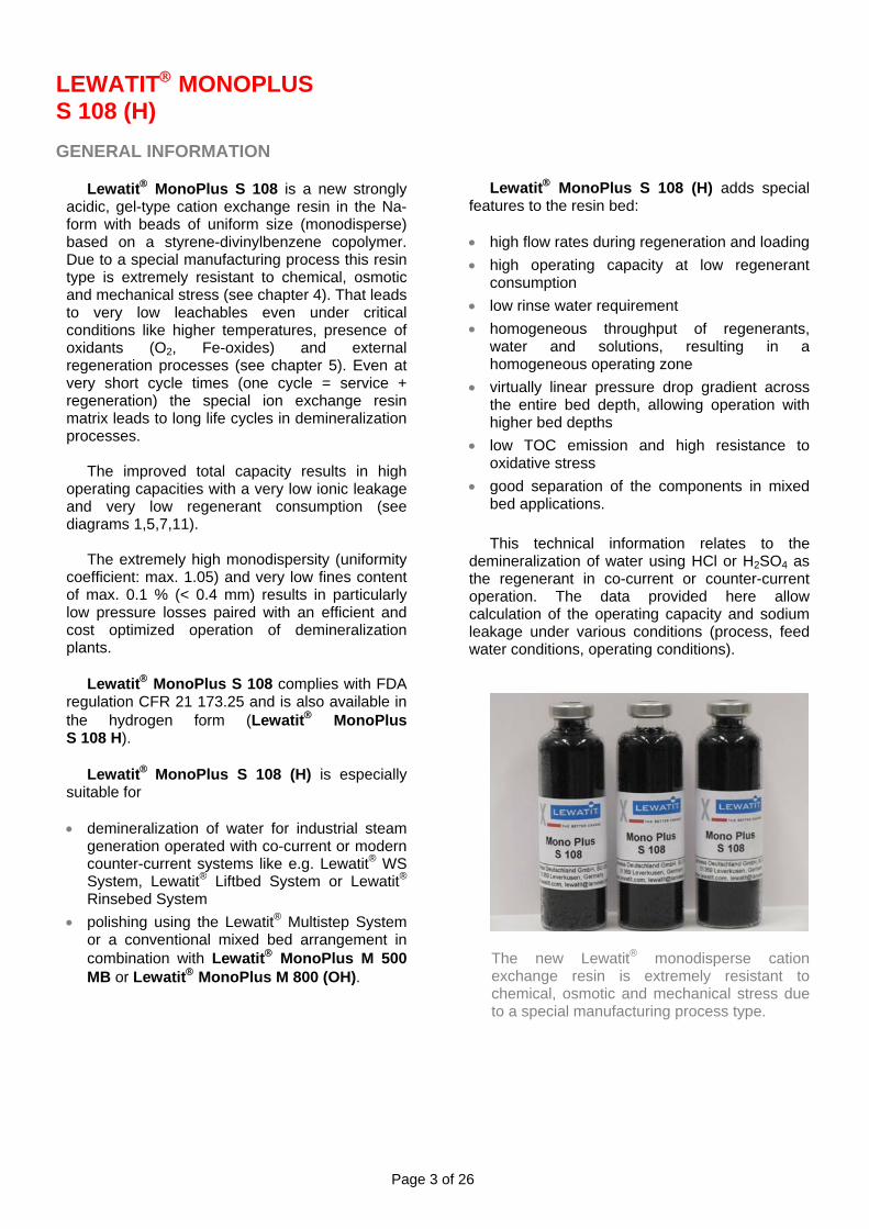
The new Lewatit® monodisperse cation exchange resin is extremely resistant to chemical, osmotic and mechanical stress due to a special manufacturing process type.
Page 4 of 26
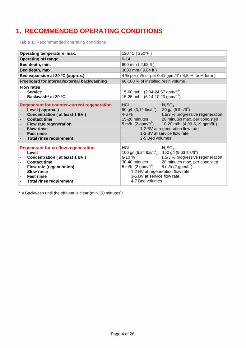
1. RECOMMENDED OPERATING CONDITIONS Table 1: Recommended operating conditions
Operating temperature, max. 120 °C ( 250°F ) Operating pH range 0-14 Bed depth, min. 800 mm ( 2,62 ft ) Bed depth, max. 3000 mm ( 9,84 ft ) Bed expansion at 20 °C (approx.) 4 % per m/h or per 0,41 gpm/ft2 ( 4,5 % for H-form ) Freeboard for internal/external backwashing 60-100 % of installed resin volume Flow rates - Service - Backwash* at 20 °C
5-60 m/h (2,04-24,57 gpm/ft2) 15-25 m/h (6,14-10,23 gpm/ft2)
Regenerant for counter-current regeneration - Level ( approx. ) - Concentration ( at least 1 BV ) - Contact time - Flow rate regeneration - Slow rinse - Fast rinse - Total rinse requirement
HCl H2SO4 50 g/l (3,12 lbs/ft3) 80 g/l (5 lbs/ft3) 4-6 % 1,5/3 % progressive regeneration 15-20 minutes 20 minutes max. per conc.step 5 m/h (2 gpm/ft2) 10-20 m/h (4,09-8,19 gpm/ft2) 1-2 BV at regeneration flow rate 1-3 BV at service flow rate 2-5 Bed volumes
Regenerant for co-flow regeneration - Level - Concentration ( at least 1 BV ) - Contact time - Flow rate (regeneration) - Slow rinse - Fast rinse - Total rinse requirement
HCl H2SO4 100 g/l (6,24 lbs/ft3) 150 g/l (9,63 lbs/ft3) 6-10 % 1,5/3 % progressive regeneration 30-40 minutes 20 minutes max. per conc.step 5 m/h (2 gpm/ft2) 5 m/h (2 gpm/ft2) 1-2 BV at regeneration flow rate 3-5 BV at service flow rate 4-7 Bed volumes
* = Backwash until the effluent is clear (min. 20 minutes)!

Page 5 of 26
2. OPERATING CAPACITY OF LEWATIT® MONOPLUS S 108
2.1 CO-CURRENT OPERATION
(HCL REGENERATION) In addition to the well-known economic and
technical disadvantages of co-current units compared with modern counter-current units, cation leakage is far higher. Co-current units can be used for applications where the higher sodium leakage is acceptable and for small units.
It is important to consider cation leakage in the
planning and dimensioning of demineralization units because it determines the conductivity and pH of the demineralized water after the weakly or strongly basic anion resin (as NaCl + CO2 or NaOH). It should also be noted that sodium leakage affects silica leakage in downstream strongly basic anion units.
20
22
24
26
28
30
32
34
36
38
40
3 4 5 6 7 8 9 10 11 12
HCl [ lbs/ft3 ]
Ope
ratin
g ca
paci
ty [
Kgr
(CaC
O3)/
ft3 ]
The operating capacity is mainly determined
by regenerant requirements. Other factors are the ratio of mono and bivalent cations and the proportion of bi-carbonate and carbonate ions in the water to be treated.
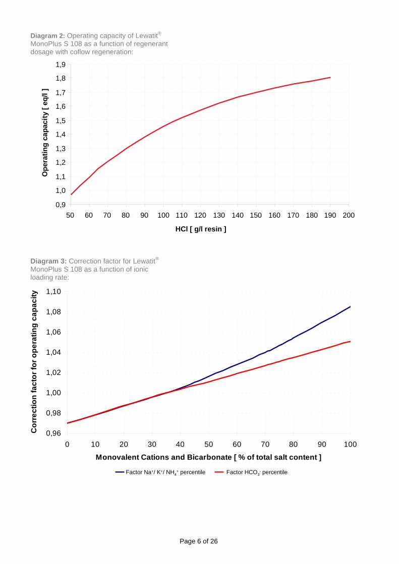
Diagram 1: Operating capacity of Lewatit® MonoPlus S 108 as a function of regenerant dosage with coflow regeneration:
Diagram 1 and 2 shows the operating
capacities of Lewatit® MonoPlus S 108 for water where the sodium and bicarbonate content is 35 % of the total salt content. The operating capacities apply to the Na supply form of the resins and an endpoint of 10 µS/cm (measured after the downstream strongly basic anion exchange resin). The correction factors for operating capacity as a function of the sodium and bicarbonate concentrations in the feed water are shown in Diagram 3.
Standard conditions • Resin as delivered (Na form) • Water temperature 15°C (59°F) • Endpoint 10 µS/cm in downstream anion
unit • Ionic loading rate max. 150 meq/h/l
(55 grs CaCO3/ft3/mn) • Sodium concentration 35% of total salt • Alkalinity 35% of total salt • Resin bed depth min. 1000 mm • Resin bed depth max. 3000 mm • Linear flow up to 40 m/h (16,4 gpm/ft2)
Page 6 of 26
0,96
0,98
1,00
1,02
1,04
1,06
1,08
1,10
0 10 20 30 40 50 60 70 80 90 10
Monovalent Cations and Bicarbonate [ % of total salt content ]0
Cor
rect
ion
fact
or fo
r ope
ratin
g ca
paci
tyDiagram 2: Operating capacity of Lewatit® MonoPlus S 108 as a function of regenerant dosage with coflow regeneration:
0,9
1,0
1,1
1,2
1,3
1,4
1,5
1,6
1,7
1,8
1,9
50 60 70 80 90 100 110 120 130 140 150 160 170 180 190 200
HCl [ g/l resin ]
Ope
ratin
g ca
paci
ty [
eq/l
]
Diagram 3: Correction factor for Lewatit® MonoPlus S 108 as a function of ionic loading rate:
Factor Na+/ K+/ NH4+ percentile Factor HCO3
- percentile
Page 7 of 26
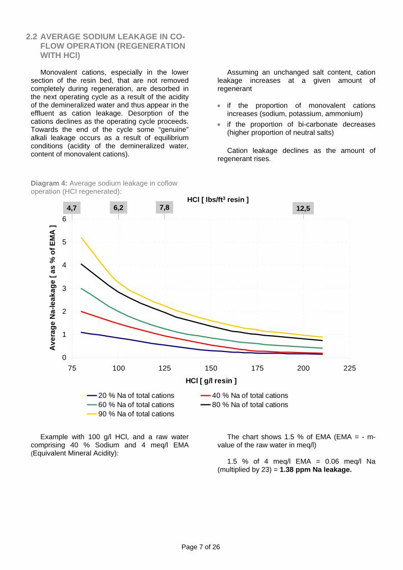
2.2 AVERAGE SODIUM LEAKAGE IN CO-FLOW OPERATION (REGENERATION WITH HCl)
Monovalent cations, especially in the lower
section of the resin bed, that are not removed completely during regeneration, are desorbed in the next operating cycle as a result of the acidity of the demineralized water and thus appear in the effluent as cation leakage. Desorption of the cations declines as the operating cycle proceeds. Towards the end of the cycle some “genuine” alkali leakage occurs as a result of equilibrium conditions (acidity of the demineralized water, content of monovalent cations).
Assuming an unchanged salt content, cation
leakage increases at a given amount of regenerant
• if the proportion of monovalent cations
increases (sodium, potassium, ammonium) • if the proportion of bi-carbonate decreases
(higher proportion of neutral salts)
Cation leakage declines as the amount of regenerant rises.
Diagram 4: Average sodium leakage in coflow operation (HCI regenerated):
Example with 100 g/l HCl, and a raw water
comprising 40 % Sodium and 4 meq/l EMA (Equivalent Mineral Acidity):
HCl [ lbs/ft3 resin ]
The chart shows 1.5 % of EMA (EMA = - m-
value of the raw water in meq/l) 1.5 % of 4 meq/l EMA = 0.06 meq/l Na
(multiplied by 23) = 1.38 ppm Na leakage.
0
1
2
3
4
5
6
75 100 125 150 175 200 225
HCl [ g/l resin ]
Ave
rage
Na-
leak
age
[ as
% o
f EM
A ]
20 % Na of total cations 40 % Na of total cations60 % Na of total cations 80 % Na of total cations90 % Na of total cations
7,86,24,7 12,5

Page 8 of 26
2.3 CO-CURRENT OPERATION (H2SO4 REGENERATION)
The operating capacity is primarily determined
by the amount of regenerant. Other key factors are the ratio of mono and bivalent cations and the proportion of hydrogen carbonate ions in the water to be treated.
Diagram 6 shows the operating capacities of
Lewatit® MonoPlus S 108 where the sodium and bicarbonate content of the water is 35 % of the total salt content. The operating capacities refer to the Na supply form and an endpoint of 10 µS/cm (measured after the downstream strongly basic anion exchange resin).
The correction factors for operating capacity as
a function of the sodium and bicarbonate concentrations in the feedwater are shown in Diagram 3.
Sulfuric acid can basically be used as a
regenerant in co-flow systems. The relatively low solubility of calcium sulfate limits the concentration of sulfuric acid regenerant that can be used. The higher the proportion of sodium and Diagram 5: Proportions and concentrations of H2SO4
magnesium ions in relation to calcium ions in the water to be treated and thus on the resin at the end of the exhaustion cycle, the higher the permissible concentration of sulfuric acid. An efficient way of overcoming this problem is to use progressive regeneration, where the concentration of the regenerant acid is increased step-wise during regeneration. Starting regeneration with a strongly diluted sulfuric acid prevents precipitation of calcium sulfate. This is followed by adding more concentrated acid, which increases the regeneration efficiency.
The temperature during regeneration should
be max. 25°C (77°F). The feed time for the sulphuric acid regenerant should not exceed 20 minutes per dilution step [e.g. 20 min for the concentration of 20 g H2SO4/kg (= 1,25 lbs/cf) solution and a further 20 min for 40 g H2SO4/kg (=2,5 lbs/cf) solution], otherwise the calcium sulfate in the column is likely to precipitate.
Diagram 5 shows the proportions and
concentrations of H2SO4 used during progressive regeneration as a function of the concentrations of Na+, Mg2+ and Ca2+ in the feedwater.
50
0 10 20 30 40 50 60 70 80 9
50
25
75
0
Na proportion of the total cation content [ % ]
5%4%
2% for 25%4% for 75%
2% for 50%4% for 50%
Mg
prop
ortio
n of
the
biva
lent
cat
ions
[ %
]
2% for 33,3%4% for 66,6%

Page 9 of 26
Standard conditions • Resin as delivered (Na form) • Water temperature 15°C (59°F) • Endpoint 10 µS/cm in downstream anion unit • Ionic loading rate max. 150 meq/h/l (55 grs CaCO3/ft3/mn) • Sodium concentration 35% of total salt • Alkalinity 35% of total salt • Resin bed depth min. 2000 mm • Resin bed depth max. 3000 mm • Linear flow up to 40 m/h (16,4 gpm/ft2)
Diagram 6: Operating capacity of Lewatit® MonoPlus S108 as a function of regenerant dosage with coflow regeneration
0,80
0,85
0,90
0,95
1,00
1,05
1,10
1,15
90 100 110 120 130 140 150 160 170 180 190 200 210 220 230 240 250 260
H2SO4 [ g/l resin ]
Ope
ratin
g ca
paci
ty [
eq/l
]
Page 10 of 26
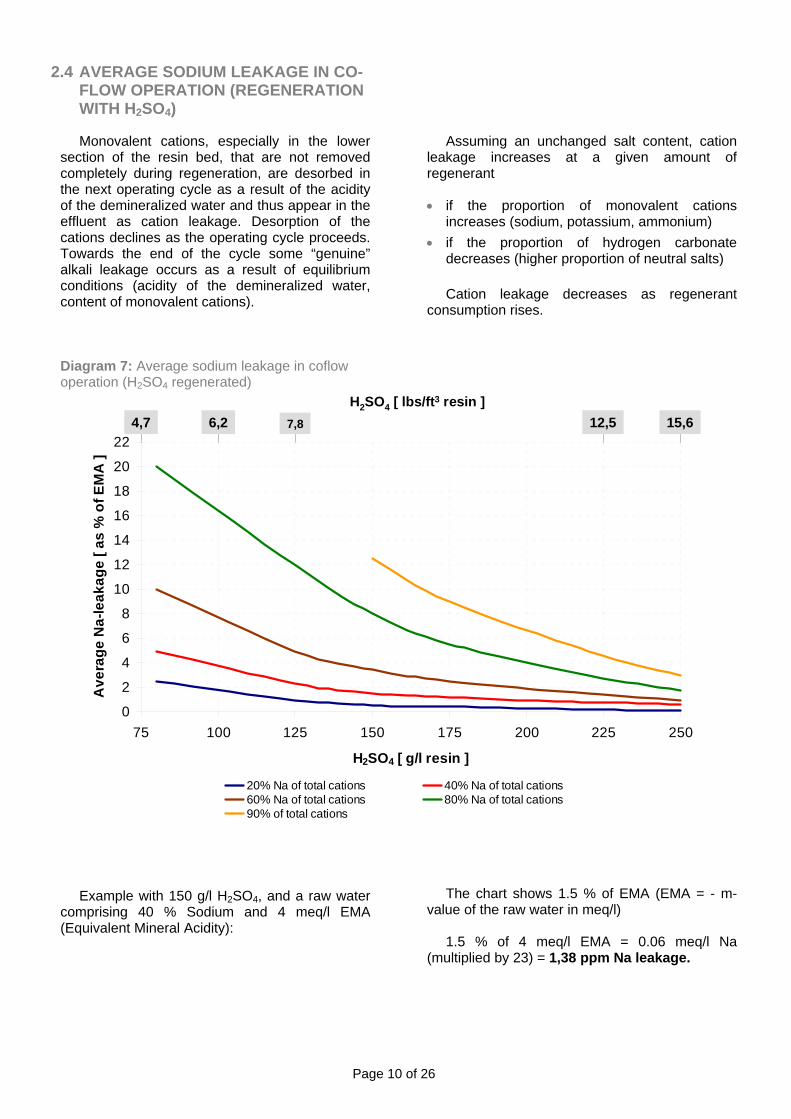
2.4 AVERAGE SODIUM LEAKAGE IN CO-FLOW OPERATION (REGENERATION WITH H2SO4)
Monovalent cations, especially in the lower
section of the resin bed, that are not removed completely during regeneration, are desorbed in the next operating cycle as a result of the acidity of the demineralized water and thus appear in the effluent as cation leakage. Desorption of the cations declines as the operating cycle proceeds. Towards the end of the cycle some “genuine” alkali leakage occurs as a result of equilibrium conditions (acidity of the demineralized water, content of monovalent cations).
Diagram 7: Average sodium leakage in coflow operation (H2SO4 regenerated)
Example with 150 g/l H2SO4, and a raw water
comprising 40 % Sodium and 4 meq/l EMA (Equivalent Mineral Acidity):
Assuming an unchanged salt content, cation
leakage increases at a given amount of regenerant
• if the proportion of monovalent cations
increases (sodium, potassium, ammonium) • if the proportion of hydrogen carbonate
decreases (higher proportion of neutral salts)
Cation leakage decreases as regenerant consumption rises.
0
2
4
6
8
10
12
14
16
18
20
22
75 100 125 150 175 200 225 250
H2SO4 [ g/l resin ]
Ave
rage
Na-
leak
age
[ as
% o
f EM
A ]
20% Na of total cations 40% Na of total cations60% Na of total cations 80% Na of total cations90% of total cations
H2SO4 [ lbs/ft3 resin ]7,86,24,7 12,5 15,6
The chart shows 1.5 % of EMA (EMA = - m-value of the raw water in meq/l)
1.5 % of 4 meq/l EMA = 0.06 meq/l Na
(multiplied by 23) = 1,38 ppm Na leakage.
Page 11 of 26
3. OPERATING CAPACITY OF LEWATIT® MONOPLUS S 108
3.1 COUNTER-CURRENT OPERATION
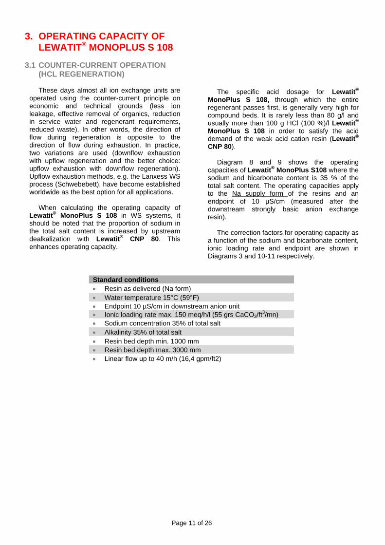
(HCL REGENERATION) These days almost all ion exchange units are
operated using the counter-current principle on economic and technical grounds (less ion leakage, effective removal of organics, reduction in service water and regenerant requirements, reduced waste). In other words, the direction of flow during regeneration is opposite to the direction of flow during exhaustion. In practice, two variations are used (downflow exhaustion with upflow regeneration and the better choice: upflow exhaustion with downflow regeneration). Upflow exhaustion methods, e.g. the Lanxess WS process (Schwebebett), have become established worldwide as the best option for all applications.
When calculating the operating capacity of
Lewatit® MonoPlus S 108 in WS systems, it should be noted that the proportion of sodium in the total salt content is increased by upstream dealkalization with Lewatit® CNP 80. This enhances operating capacity.
The specific acid dosage for Lewatit®
MonoPlus S 108, through which the entire regenerant passes first, is generally very high for compound beds. It is rarely less than 80 g/l and usually more than 100 g HCl (100 %)/l Lewatit® MonoPlus S 108 in order to satisfy the acid demand of the weak acid cation resin (Lewatit® CNP 80).
Diagram 8 and 9 shows the operating
capacities of Lewatit® MonoPlus S108 where the sodium and bicarbonate content is 35 % of the total salt content. The operating capacities apply to the Na supply form of the resins and an endpoint of 10 µS/cm (measured after the downstream strongly basic anion exchange resin).
The correction factors for operating capacity as
a function of the sodium and bicarbonate content, ionic loading rate and endpoint are shown in Diagrams 3 and 10-11 respectively.
Standard conditions • Resin as delivered (Na form) • Water temperature 15°C (59°F) • Endpoint 10 µS/cm in downstream anion unit • Ionic loading rate max. 150 meq/h/l (55 grs CaCO3/ft3/mn) • Sodium concentration 35% of total salt • Alkalinity 35% of total salt • Resin bed depth min. 1000 mm • Resin bed depth max. 3000 mm • Linear flow up to 40 m/h (16,4 gpm/ft2)

Page 12 of 26
Diagram 8: Operating capacity of Lewatit® MonoPlus S 108 as a function of regenerant dosage with down flow reverse regeneration
1,1
1,2
1,3
1,4
1,5
1,6
1,7
1,8
1,9
50 60 70 80 90 100 110 120 130 140 150 160 170 180 190 200
HCl [ g/l resin ]
Ope
ratin
g ca
paci
ty [
eq/l
]
Diagram 9: Operating capacity of Lewatit® MonoPlus S 108 as a function of regenerant dosage with down flow reverse regeneration
50
75
100
125
150
175
200
225
250
275
300
2 4 6 8 10 12 14
HCl [lbs/ft3]
Ope
ratin
g ca
paci
ty [K
gr(C
aCO
3)/ft3

Page 13 of 26
Diagram 10: Correction factor for Lewatit® MonoPlus S 108 as a function of ionic loading rate
0,84
0,86
0,88
0,90
0,92
0,94
0,96
0,98
1,00
150 200 250 300 350 400 450 500
Ionic loading rate [meq/h*l resin]
Cor
rect
ion
fact
or o
pera
ting
capa
city
Diagram 11: Correction factor for Lewatit® MonoPlus S 108 as a function of endpoint
0,80
0,85
0,90
0,95
1,00
1,05
2 3 4 5 6 7 8 9
Endpoint [ µs/cm ]
Cor
rect
ion
fact
or fo
r ope
ratin
g ca
paci
ty
10
Page 14 of 26
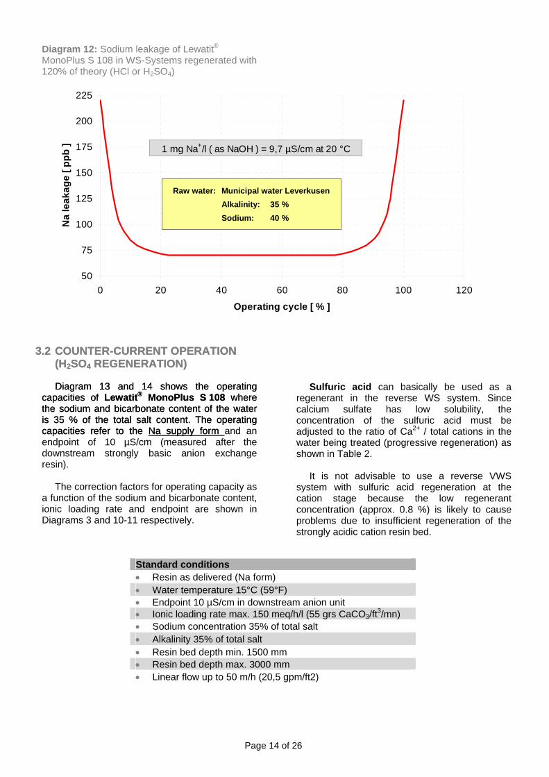
Diagram 12: Sodium leakage of Lewatit® MonoPlus S 108 in WS-Systems regenerated with 120% of theory (HCl or H2SO4)
3.2 COUNTER-CURRENT OPERATION
(H2SO4 REGENERATION) 3.2 COUNTER-CURRENT OPERATION
(H
Diagram 13 and 14 shows the operating capacities of Lewatit® MonoPlus S 108 where the sodium and bicarbonate content of the water is 35 % of the total salt content. The operating capacities refer to the Na supply form
Diagram 13 and 14 shows the operating capacities of Lewatit MonoPlus S 108 where the sodium and bicarbonate content of the water is 35 % of the total salt content. The operating capacities refer to the
2SO4 REGENERATION)
®
Na supply form and an endpoint of 10 µS/cm (measured after the downstream strongly basic anion exchange resin).
The correction factors for operating capacity as
a function of the sodium and bicarbonate content, ionic loading rate and endpoint are shown in Diagrams 3 and 10-11 respectively.
50
75
100
125
150
175
200
225
0 20 40 60 80 100 12
Operating cycle [ % ]
Na
leak
age
[ ppb
]
0
1 mg Na+/l ( as NaOH ) = 9,7 µS/cm at 20 °C
Raw water: Municipal water LeverkusenAlkalinity: 35 %Sodium: 40 %
Sulfuric acid can basically be used as a
regenerant in the reverse WS system. Since calcium sulfate has low solubility, the concentration of the sulfuric acid must be adjusted to the ratio of Ca2+ / total cations in the water being treated (progressive regeneration) as shown in Table 2.
It is not advisable to use a reverse VWS
system with sulfuric acid regeneration at the cation stage because the low regenerant concentration (approx. 0.8 %) is likely to cause problems due to insufficient regeneration of the strongly acidic cation resin bed.
Standard conditions • Resin as delivered (Na form) • Water temperature 15°C (59°F) • Endpoint 10 µS/cm in downstream anion unit • Ionic loading rate max. 150 meq/h/l (55 grs CaCO3/ft3/mn) • Sodium concentration 35% of total salt • Alkalinity 35% of total salt • Resin bed depth min. 1500 mm • Resin bed depth max. 3000 mm • Linear flow up to 50 m/h (20,5 gpm/ft2)

Page 15 of 26
Diagram 13: Operating capacity of Lewatit® MonoPlus S 108 as a function of regenerant dosage with down flow reverse regeneration
0,70
0,75
0,80
0,85
0,90
0,95
1,00
1,05
1,10
1,15
1,20
1,25
50 60 70 80 90 100 110 120 130 140 150 160 170 180 190 200H2SO4 [ g/l resin ]
Ope
ratin
g ca
paci
ty [
eq/l
]
Diagram 14: Operating capacity of Lewatit® MonoPlus S 108 as a function of regenerant dosage with down flow reverse regeneration
15
17
19
21
23
25
27
3 4 5 6 7 8 9 10 11 12 13
H2SO4 [ lbs/ft3 ]
Ope
ratit
ng c
apac
ity [
Kgr
(CaC
O3)/
ft3

Page 16 of 26
3.2.1 PERMITTED H2SO4 CONCENTRATION (PROGRESSIVE)
The temperature during regeneration should be max. 25°C (77°F). The feed time for the sulphuric acid regenerant should not exceed 20 minutes per dilution step [e.g. 20 min for the concentration of 15 g H2SO4/kg (= 0,94 lbs/cf) solution and a further 20 min for 30 g H2SO4/kg (= 1,87 lbs/cf) solution], otherwise the calcium sulfate in the column is likely to precipitate.
Table 2: Progressive regeneration with H2SO4
Content Ca2+ of total salt in feed water Proportion of 1.5 % H2SO4 solution in regenerant, remainder 3 % solution
< 15% 0%
> 15% 25%
> 20% 33%
> 50% 50%
> 65% 100%

Page 17 of 26
4. OSMOTIC STABILITY OF LEWATIT® MONOPLUS S 108 (H)
Stability is another key parameter for
characterization of ion exchange resins. As far as life expectancy of the resins and the operating reliability of a unit is concerned, osmotic and mechanical ability are of immense significance.
Nevertheless, it is difficult to simulate in a
single test all the various highly complex influences of both a chemical and mechanical nature that affect the ion exchange resin in an industrial-scale facility.
During its normal life time, a resin is
exhausted, regenerated and possibly transported through pipes for external regeneration and/or backwashing many times over. Several tests have therefore been developed to assess the stability of a resin to chemical and mechanical influences.
Diagram 15: Osmotic Stability SAC
Diagram 15 as well as the pictures from microscope display the outstanding mechanical properties of Lewatit® MonoPlus S 108 (H) in compar ison to severa l s tandard res ins .
4.1 OSMOTIC SHOCK TEST
The osmotic shock test (swelling stability) simulates the stresses in the resin matrix occurring during regeneration and is thus a measure of the chemical-osmotic stability of an ion exchange resin. Through alternate treatment with acid and alkali over 200 cycles, the cation exchange resin changes between the H+ and Na+-form. Between these two forms, the resin undergoes the maximum volume change (8-10%). The resultant internal stresses, which affect the resin matrix directly, are extremely high.
Here in turn we can say: the higher the
osmotic stability, the longer the service life of the ion exchange resin.
The number of perfect ion exchange beads
remaining after osmotic shock test procedure (200 cycles) gives an indication of the stability of the ion exchange resin in practical use. Higher stability leads to less pressure loss, higher capacity and lower risk of clogging of any distributing systems or resin traps. The lower attrition leads to less cross-contamination in mixed bed resin systems too.
50
55
60
65
70
75
80
85
90
95
100
MonoPlus S 108 H Competitor 1 Competitor 2 Competitor 3
Perf
ect b
eads
[ %
]
Page 18 of 26
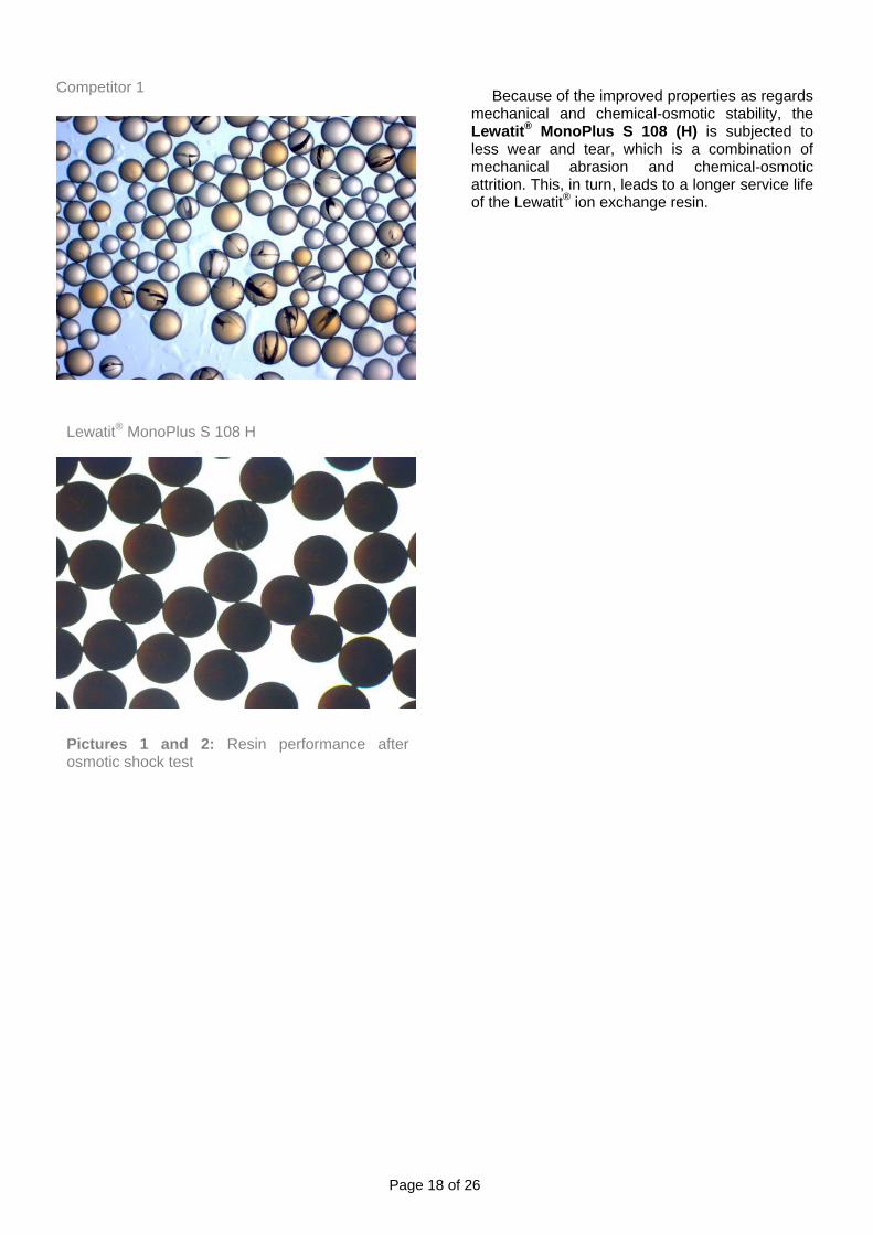
Competitor 1
Lewatit® MonoPlus S 108 H
Pictures 1 and 2: Resin performance after osmotic shock test
Because of the improved properties as regards
mechanical and chemical-osmotic stability, the Lewatit® MonoPlus S 108 (H) is subjected to less wear and tear, which is a combination of mechanical abrasion and chemical-osmotic attrition. This, in turn, leads to a longer service life of the Lewatit® ion exchange resin.
Page 19 of 26
5. LEACHABLES Oxidative attack on the matrix of cation
exchange resins can result in soluble polystyrene sulfonic acid (PSS) compounds of varying chain lengths (molecular weights) being split off (secondary leaching or long-term leaching behavior). The release of such leachables from strongly dissociated cation exchange resins in condensate treatment plants can subsequently lead to problems in the water-steam circuit through the concentration of sulfate in, for example, steam generators with the associated risks of corrosion (crevice corrosion).
Most of these leachables (PSS) are removed
reversibly by the strong dissociated anion mixed bed component or (in single column arrangement) by a strong dissociated anion filter column installed downstream. Tests and experience have shown that PSS with a molecular weight of < 2000 g/mol can cause irreversible fouling (poisoning) of the anion component, leading to a deterioration of anion (mixed bed) kinetics (leakage of sulfate and PSS).
5.1 LEACHABLES TEST METHOD
The leaching behavior of strong dissociated
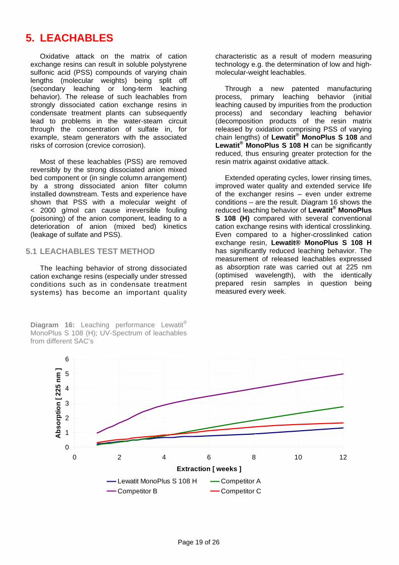
cation exchange resins (especially under stressed conditions such as in condensate treatment systems) has become an important quality Diagram 16: Leaching performance Lewatit®
MonoPlus S 108 (H); UV-Spectrum of leachables from different SAC’s
characteristic as a result of modern measuring technology e.g. the determination of low and high-molecular-weight leachables.
Through a new patented manufacturing
process, primary leaching behavior (initial leaching caused by impurities from the production process) and secondary leaching behavior (decomposition products of the resin matrix released by oxidation comprising PSS of varying chain lengths) of Lewatit® MonoPlus S 108 and Lewatit® MonoPlus S 108 H can be significantly reduced, thus ensuring greater protection for the resin matrix against oxidative attack.
Extended operating cycles, lower rinsing times,
improved water quality and extended service life of the exchanger resins – even under extreme conditions – are the result. Diagram 16 shows the reduced leaching behavior of Lewatit® MonoPlus S 108 (H) compared with several conventional cation exchange resins with identical crosslinking. Even compared to a higher-crosslinked cation exchange resin, Lewatit® MonoPlus S 108 H has significantly reduced leaching behavior. The measurement of released leachables expressed as absorption rate was carried out at 225 nm (optimised wavelength), with the identically prepared resin samples in question being measured every week.
0
1
2
3
4
5
6
0 2 4 6 8 10
Extraction [ weeks ]
Abs
orpt
ion
[ 225
nm
]
12
Lewatit MonoPlus S 108 H Competitor ACompetitor B Competitor C

Page 20 of 26
6. HYDRAULIC CHARACTERISTICS
Diagram 17: Bed expansion Lewatit® MonoPlus S 108 (H) as a function of linear flowrate
6.1 BED EXPANSION Under extreme conditions, suspended solids
accumulate on the resin bed resulting in high pressure drop and poor performance due to hydraulic channeling. Occasional backwashing may be necessary to remove impurities or resin fines and thus reduce the pressure drop (delta p). Due to the outstanding monodispersity (UC: max. 1.05) of Lewatit® MonoPlus S 108 the water demand for backwash steps is significantly reduced. Diagram 18 shows the correction factor for bed expansion as a function of temperature.
Flow rate [ gpm/ft2 ]
0
10
20
30
40
50
60
70
80
90
100
0 5 10 15 20 250 5 10 15 20 25Linear flow rate [ m/h ]
Bed
exp
ansi
on [
% ]
2 1864 0
Temperature 20 °C ( 68°F )
Na-Form H-Form Ca-Form
Page 21 of 26
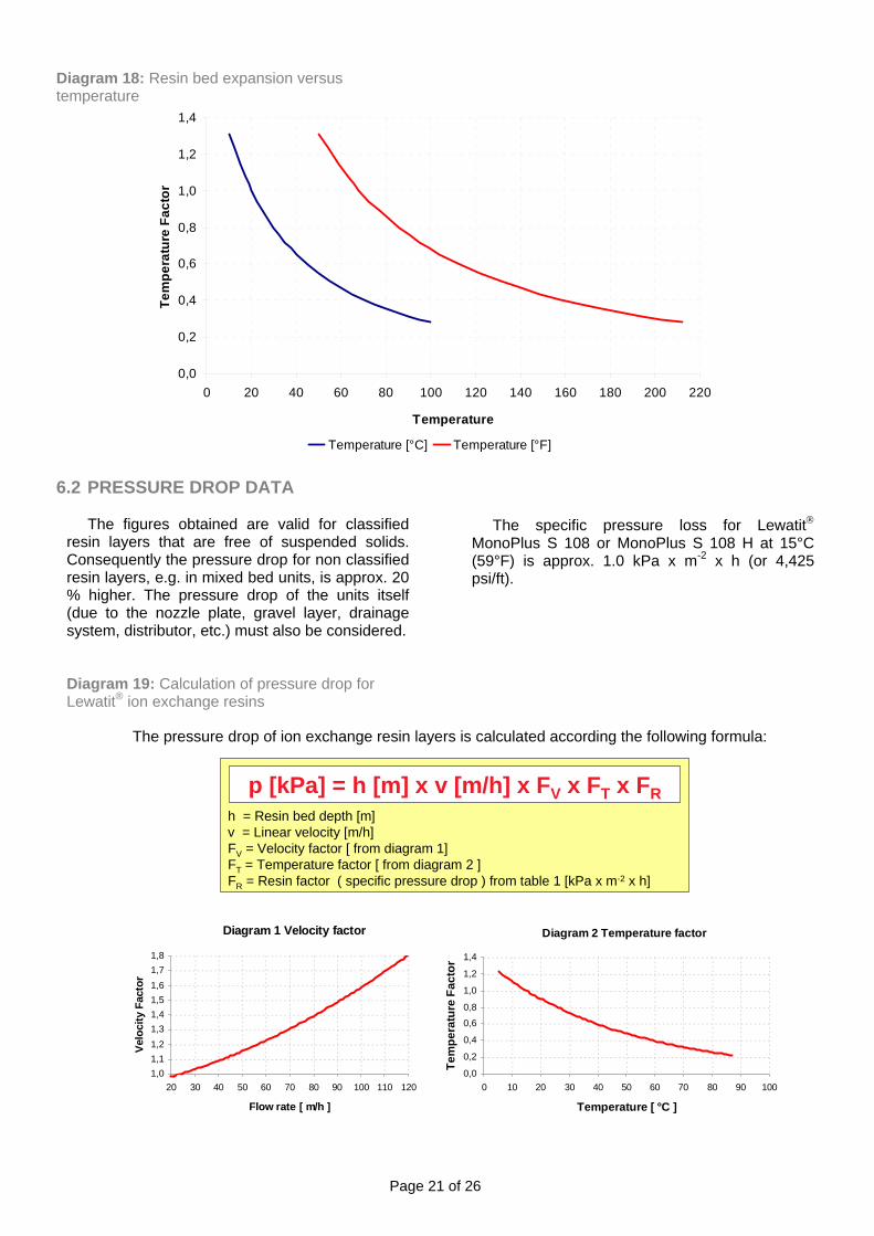
Diagram 18: Resin bed expansion versus temperature 6.2 PRESSURE DROP DATA
The figures obtained are valid for classified
resin layers that are free of suspended solids. Consequently the pressure drop for non classified resin layers, e.g. in mixed bed units, is approx. 20 % higher. The pressure drop of the units itself (due to the nozzle plate, gravel layer, drainage system, distributor, etc.) must also be considered.
Diagram 19: Calculation of pressure drop for Lewatit® ion exchange resins
0,0
0,2
0,4
0,6
0,8
1,0
1,2
1,4
0 20 40 60 80 100 120 140 160 180 200 220
Temperature
Tem
pera
ture
Fac
tor
Temperature [°C] Temperature [°F]
The specific pressure loss for Lewatit®
MonoPlus S 108 or MonoPlus S 108 H at 15°C (59°F) is approx. 1.0 kPa x m-2 x h (or 4,425 psi/ft).
h = Resin bed depth [m]v = Linear velocity [m/h]FV = Velocity factor [ from diagram 1]FT = Temperature factor [ from diagram 2 ]FR = Resin factor ( specific pressure drop ) from table 1 [kPa x m-2 x h]
The pressure drop of ion exchange resin layers is calculated according the following formula:
p [kPa] = h [m] x v [m/h] x FV x FT x FR
Diagram 1 Velocity factor
1,01,11,21,31,41,51,61,71,8
20 30 40 50 60 70 80 90 100 110 120
Velo
city
Fac
tor
Flow rate [ m/h ]
Diagram 2 Temperature factor
0,0
0,2
0,4
0,6
0,8
1,0
1,2
1,4
0 10 20 30 40 50 60 70 80 90 100
Tem
pera
ture
Fac
tor
Temperature [ °C ]
Page 22 of 26
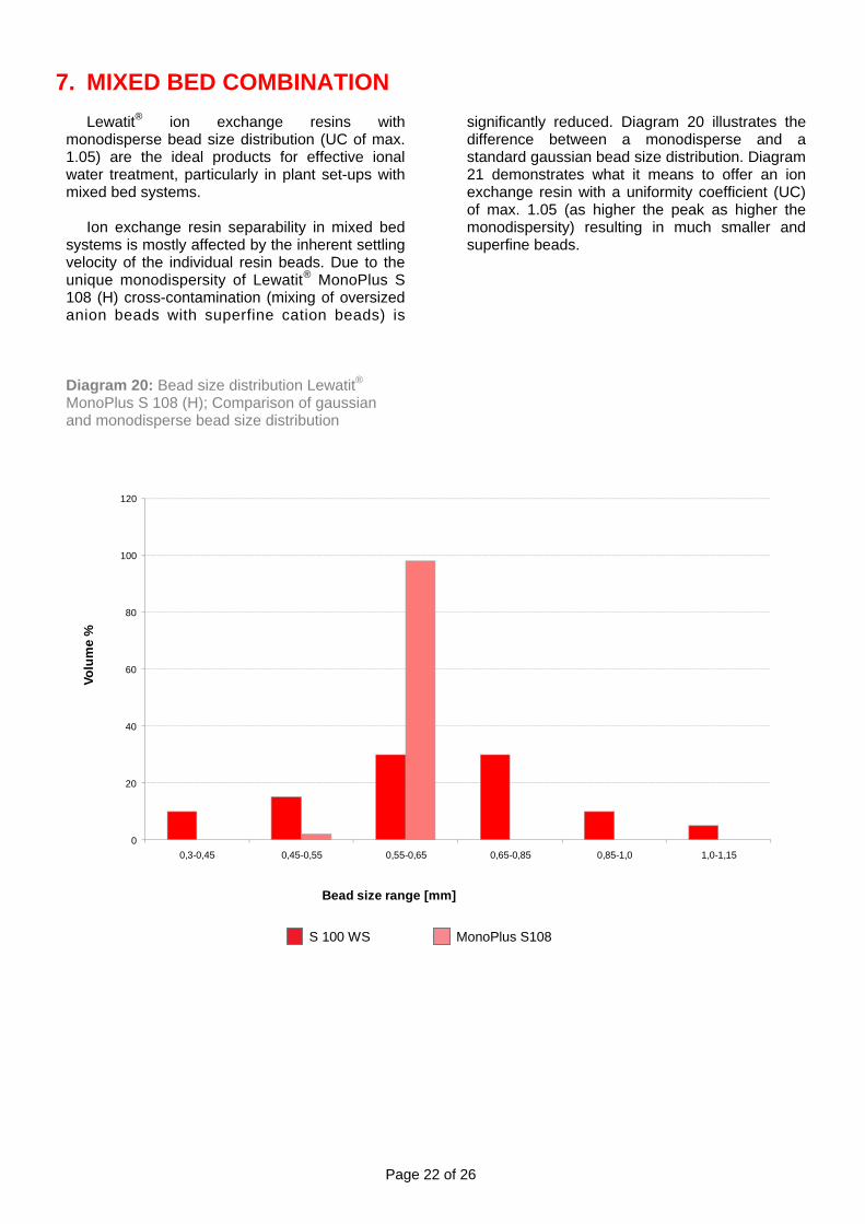
7. MIXED BED COMBINATION Lewatit® ion exchange resins with
monodisperse bead size distribution (UC of max. 1.05) are the ideal products for effective ional water treatment, particularly in plant set-ups with mixed bed systems.
Ion exchange resin separability in mixed bed
systems is mostly affected by the inherent settling velocity of the individual resin beads. Due to the unique monodispersity of Lewatit® MonoPlus S 108 (H) cross-contamination (mixing of oversized anion beads with superfine cation beads) is Diagram 20: Bead size distribution Lewatit® MonoPlus S 108 (H); Comparison of gaussian and monodisperse bead size distribution
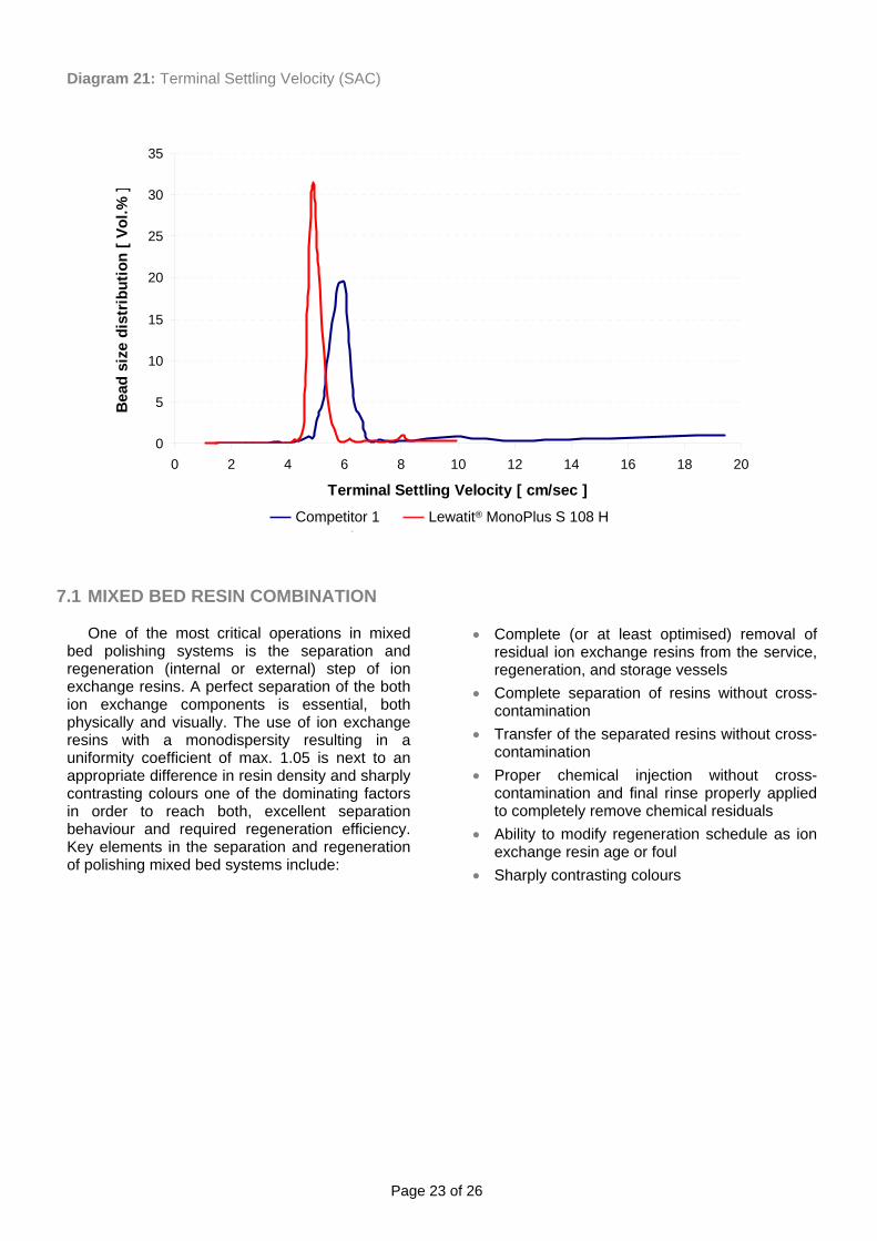
significantly reduced. Diagram 20 illustrates the difference between a monodisperse and a standard gaussian bead size distribution. Diagram 21 demonstrates what it means to offer an ion exchange resin with a uniformity coefficient (UC) of max. 1.05 (as higher the peak as higher the monodispersity) resulting in much smaller and superfine beads.
0
20
40
60
80
100
120
0,3-0,45 0,45-0,55 0,55-0,65 0,65-0,85 0,85-1,0 1,0-1,15
Volu
me
%
Bead size range [mm]
MonoPlus S108S 100 WS
Page 23 of 26
Diagram 21: Terminal Settling Velocity (SAC) 7.1 MIXED BED RESIN COMBINATION
One of the most critical operations in mixed
bed polishing systems is the separation and regeneration (internal or external) step of ion exchange resins. A perfect separation of the both ion exchange components is essential, both physically and visually. The use of ion exchange resins with a monodispersity resulting in a uniformity coefficient of max. 1.05 is next to an appropriate difference in resin density and sharply contrasting colours one of the dominating factors in order to reach both, excellent separation behaviour and required regeneration efficiency. Key elements in the separation and regeneration of polishing mixed bed systems include:
0
5
10
15
20
25
30
35
0 2 4 6 8 10 12 14 16 18 20
Terminal Settling Velocity [ cm/sec ]
Bea
d si
ze d
istr
ibut
ion
[ Vol
.% ]
Competitor 1 Lewatit MonoPlus S 108 HCompetitor 1 Lewatit® MonoPlus S 108 H
• Complete (or at least optimised) removal of residual ion exchange resins from the service, regeneration, and storage vessels
• Complete separation of resins without cross-contamination
• Transfer of the separated resins without cross-contamination
• Proper chemical injection without cross-contamination and final rinse properly applied to completely remove chemical residuals
• Ability to modify regeneration schedule as ion exchange resin age or foul
• Sharply contrasting colours
Page 24 of 26
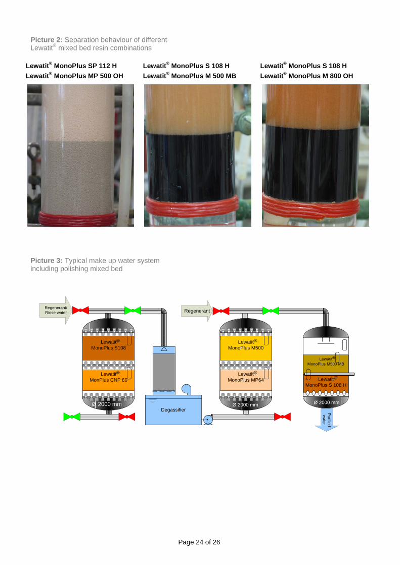
Picture 2: Separation behaviour of different Lewatit® mixed bed resin combinations
Lewatit® MonoPlus SP 112 H Lewatit® MonoPlus S 108 H Lewatit® MonoPlus S 108 H Lewatit® MonoPlus MP 500 OH Lewatit® MonoPlus M 500 MB Lewatit® MonoPlus M 800 OH
Picture 3: Typical make up water system including polishing mixed bed
Degassifier
Lewatit MonoPlus M500
Lewatit MonoPlus MP64
Lewatit MonoPlus S108
LewatitMonPlus CNP 80 Lewatit
MonoPlus S 108 H
LewatitMonoPlus M500 MB
Purified w
ater
Ø 2000 mm Ø 2000 mm Ø 2000 mm
Regenerant/Rinse water Regenerant
®
® ®
®
®
®
Page 25 of 26
8. EPILOGUE The examples in this brochure demonstrate
that modern ion exchange resins in combination with advanced ion exchange technology can be used in different ways to treat raw waters from undesirable positive and negative ions. Ion exchange technologies are powerful tools on the top shelf of the demineralization water engineer’s toolbox. They can be used alone or in combination with other water pre treatment methods.
Water treatment concepts involving ion
exchange resins can be designed in different ways, from the easy to design coflow system up to the most modern compound fluidized bed process (VWS-System). Process-integrated measures that directly operate on process streams in the heart of the process can be employed too.
In order to satisfy demanding requirements,
LANXESS developed monodisperse resins of the second generation with the trade name „Lewatit® MonoPlus“. Due to the high monodispersity (uniformity coefficient max. 1.05) and due to its homogeneous network structure and interpenetrating network, Lewatit® MonoPlus has far better kinetic properties than conventional ion exchange resins.
The perfectly coordinated diameters and
densities of the individual monodisperse ion exchange resin grades guarantee more effective and more reliable backwashing without risk of resin loss. In mixed bed systems, a sharp separation zone is observed after resin separation by backwashing.
Stability is another key parameter for the
characterization of ion exchange resins. As far as the life expectancy of the resin and the operating reliability of a demineralization unit is concerned, osmotic and mechanical stability are of immense significance.
With the advantages of this new resin
generation, such as an average monodispersity of approx. 90 %, higher operating capacity and higher osmotic and mechanical stability, the use of this kind of high tech ion exchange resin is now state of the art in all modern water treatment systems as well as in conventional coflow systems worldwide.
It is important to mention that the development
of modern ion exchange resins is not finished. LANXESS is always eager to further improve their products and to create new products for new fields of application. In this way, LANXESS is helping to insure that tailor-made products for the treatment of raw waters are available both now and will be in future times; for the sake of our environment and for the sake of all of us.

DISCLAIMER This information and our technical advice – whether verbal, in writing or by way of trials – are given in good faith but without warranty, and this also applies where proprietary rights of third parties are involved. Our advice does not release you from the obligation to check its validity and to test our products as to their suitability for the intended processes and uses. The application, use and processing of our products and the products manufactured by you on the basis of our technical advice are beyond our control and, therefore, entirely your own responsibility. Our products are sold in accordance with the current version of our General Conditions of Sale and Delivery. The above formulation is intended solely as a guide for our business partners and others interested in our products. As the conditions of use and application of the suggested formulation are beyond our control, it is imperative that it be tested to determine, to your satisfaction, whether it is suitable for your intended use(s) and application(s). This application-specific analysis at least must include testing to determine suitability from a technical, as well as health, safety and environmental standpoints. Further, although the ingredients, quantities thereof and properties of compounds or finished goods mentioned herein reflect our recommendation at the time of publication, this guide may not be subject to continuous review and/or updating, and you agree that use is undertaken at your sole risk. All information is given without warranty or guarantee, and it is expressly understood and agreed that you assume, and hereby expressly release us from all liability, in tort, contract or otherwise, incurred in connection with the use of this guide. Lewatit® and MonoPlus® are registered trademarks of LANXESS Deutschland GmbH.
CONTACTS Regional Business Center Headquarter LANXESS Deutschland GmbH Leverkusen, Germany Fax +49-214-3050621 [email protected] Europe LANXESS Deutschland GmbH Langenfeld, Germany Fax +49-2173-2033-311 [email protected] NAFTA LANXESS Sybron Chemicals Inc. Birmingham, NJ, USA Fax +1-609-894-8641 [email protected] Asia Pacific LANXESS Pte Ltd Singapore Fax +65-6-2666959 [email protected] Japan & South Korea LANXESS K.K. 1-6-5 Marunouchi Chiyoda-ku Fax +81 3 5219 9775 [email protected] South America LANXESS Industria de Produtos Quimicos e Plasticos Ltda Sao Paulo, Brazil Fax +55-11-37412548 [email protected] www.lewatit.com Author: Burkhard Brings, Manager Technical Marketing, Industrial Water Treatment (IWT) Edition: 2009-09 ©2009 – All Rights Reserved LANXESS Deutschland GmbH
Page 26 of 26
Related Documents