Submitted to: Workshop On Space Charge Physics In High Intensity Hadron Rings S$elter Island, N.Y. May 4-7, 1998 $ BNL-65618 SNS Ac(cumulaltor Ring Design and Spac(e Charge Considerations W. T. Weng AGSDepartment, Brookhzven National Laboratory, Upton, NY 11973 Workshop on Space Charge Physics In High Intensit~!Hardron Rings . May 4-’7, 1998 Shelter Island, Long Island, NY OFFICIALFILECOPY

Welcome message from author
This document is posted to help you gain knowledge. Please leave a comment to let me know what you think about it! Share it to your friends and learn new things together.
Transcript
Submitted to: Workshop On Space Charge Physics In High Intensity Hadron RingsS$elter Island, N.Y. May 4-7, 1998
$
BNL-65618
SNS Ac(cumulaltorRing Designand Spac(eCharge Considerations
W. T. Weng
AGSDepartment, Brookhzven National Laboratory, Upton, NY 11973
Workshop on Space Charge PhysicsIn High Intensit~!Hardron Rings.
May 4-’7, 1998
Shelter Island, Long Island, NY
OFFICIALFILECOPY
SNS Accumulatcm Ring Designand Space Charge Considerations 1
W.T. Weng
AGS Department, B;rookhaven National Laboratoy, Upton, NY 11973
Abstract. The goal of the proposed SpallaticmNeutron Source (SNS) is to provide ashort pulseproton beam of about 0.5ps with a,veragebeam power of lMW. To achievesuch purpose, a proton storage ring operated at 60Hz with 1x 10¹⁴protons per pulseat lGeV is required. The Accumulator Rh-ig (AR) receives lmsec long 1-1- beambunches of 28mA from a lGeV linac. Scope and design performancegoals of the ARare presented. About 1200 turns of charge exchange injection is needed to accumulatelmA in the ring. After a brief descriptionof the lattice designand machineperformanceparameters,spacecharge related issues,such as: tune shifts, stopband corrections, halogenerationand beam collimation etc. will be discussed.
I INTRODUCTION
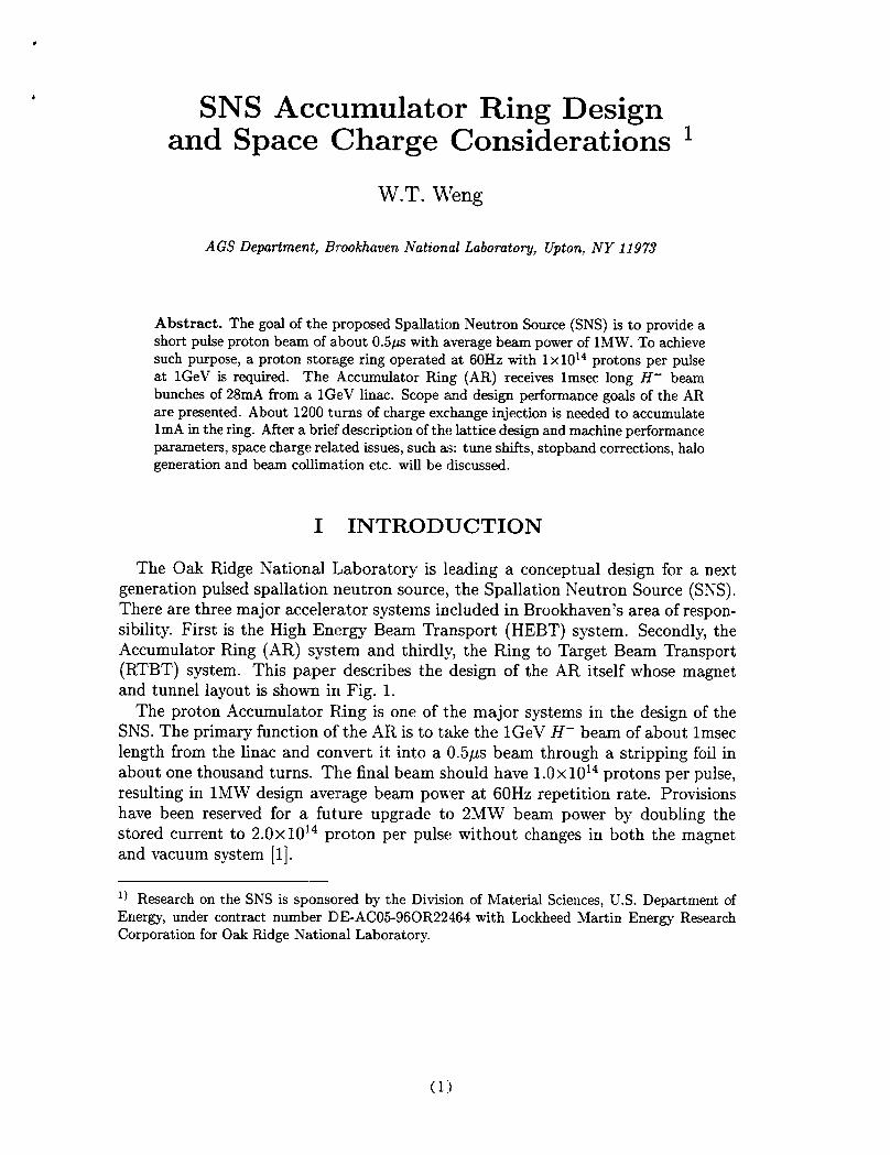
The Oak Ridge National Laboratory is leading a conceptual design for a nextgeneration pulsed spallation neutron source, the Spallation Neutron Source (SNS).There are three major accelerator systems included in Brookhaven’s area of respon-sibility. First is the High Energy Beam Transport (HEBT) system. Secondly, theAccumulator Ring (AR) system and thirdly, the Ring to Target Beam Transport(RTBT) system. This paper describes the design of the AR itself whose magnetand tunnel layout is shown in Fig. 1.
The proton Accumulator FLing is one of the major systems in the design of theSNS. The primary function of’the AR is to take the lGeV H- beam of about lmseclength from the linac and convert it into a 0.5ps beam through a stripping foil inabout one thousand turns. The final beam slhould have 1.0x 10¹⁴ protons per pulse,resulting in lMW design average beam power at 60Hz repetition rate. Provisionshave been reserved for a future upgrade to 2MW beam power by doubling thestored current to 2.0x10¹⁴ proton per pulse without changes in both the magnetand vacuum system [1].
1) Research on the SNS is sponsored by the Division of Material Sciences, U.S. DepartmentofEnergy, under contract number EIEAC05-96C)R22464 with Lockheed Martin Energy ResearchCorporation for Oak Ridge National Laboratory.
.5 m -. . . . . - .45,T-
.. 1.55 m --- 1.5 m -
ARC -iAL~ CELL
FIGURE 1. Layout of the accumulatorring.
One of the major performance requirements is to keep the average uncontrolledparticle loss during the accumulation time to less than 2.0x10⁻⁴ per pulse. Thereason of this stringent requirement is to keep the residual radiation to such a levelthat the hands-on maintenance is possible except for a few localized areas, such as:injection, extraction and collimation. To achieve this goal, special care have beenexercised in the H– stripping, the RF stacking, and the collimator design.
In Section 2, the lattice design, H- injection and RF stacking process of theSNS accumulator ring will be described. Space charge tune shift and resonancestopband corrections is presented in Section 3. The study in halo formation andits implications on the collimator placement and design is given in Section 4.
II LATTICE, H- INJECTION AND RF STACKING
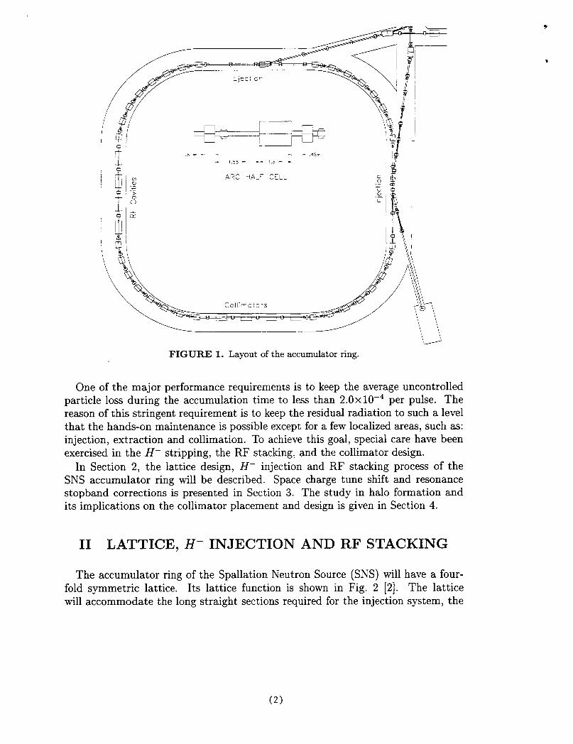
The accumulator ring of the Spallation Neutron Source (SNS) will have a four-fold symmetric lattice. Its lattice function is shown in Fig. 2 [2]. The latticewill accommodate the long straight sections required for the injection system, the
(2)
n-10 0
IL
METERS
FIGTJRE 2. Accumulator lattice functions.
extraction system, the RF cavities, and the beam scraping system. The straightsections will be dispersion free, which is Idesirable, especially for the RF cavitiesand the injection system. The lattice wdl provide ease of betatron tuning andflexibility of operation. U:nlike lattices OF lower symmetry, a lattice of four-foldsymmetry will assure that there are no dangerous betatron structure resonancesother than for the integer tune. Lattice functions and other salient performanceand design parameters of the accumulator ring are summarized in Table 1.
The most demanding s~~tem in the design of the lMW short pulse spallationneutron source is the H– multi-turn injection into the storage ring [3]. For the SNSaccumulator ring, a carbon foil of 400pg/cm2 is assumed. The stripping efficiencyfor lGeV incident H- beam is about 99.8%. The temperature rise for the lMWdesign is estimated to be about 3200”C. In addition, it has been found that
a.
b.
c.
d.
Stripping losses in passage of the H- beam through the B=3kG field in a DCbump dipole magnet upstream of the stripper foil are negligible.
A fraction f(HO) =8.19 x10⁻³ of the incident H- beam will emerge as H“from a 400pg/cm2 carbon stripper foil and must be disposed of in an externaldump.
Field ionization of the HOcomponent in the B=2.41kG field of a quadrupledownstream of the foil will lead to negligible uncontrolled losses.
Fractional losses from nuclear non-elastic interactions in the foil as low as
(3)
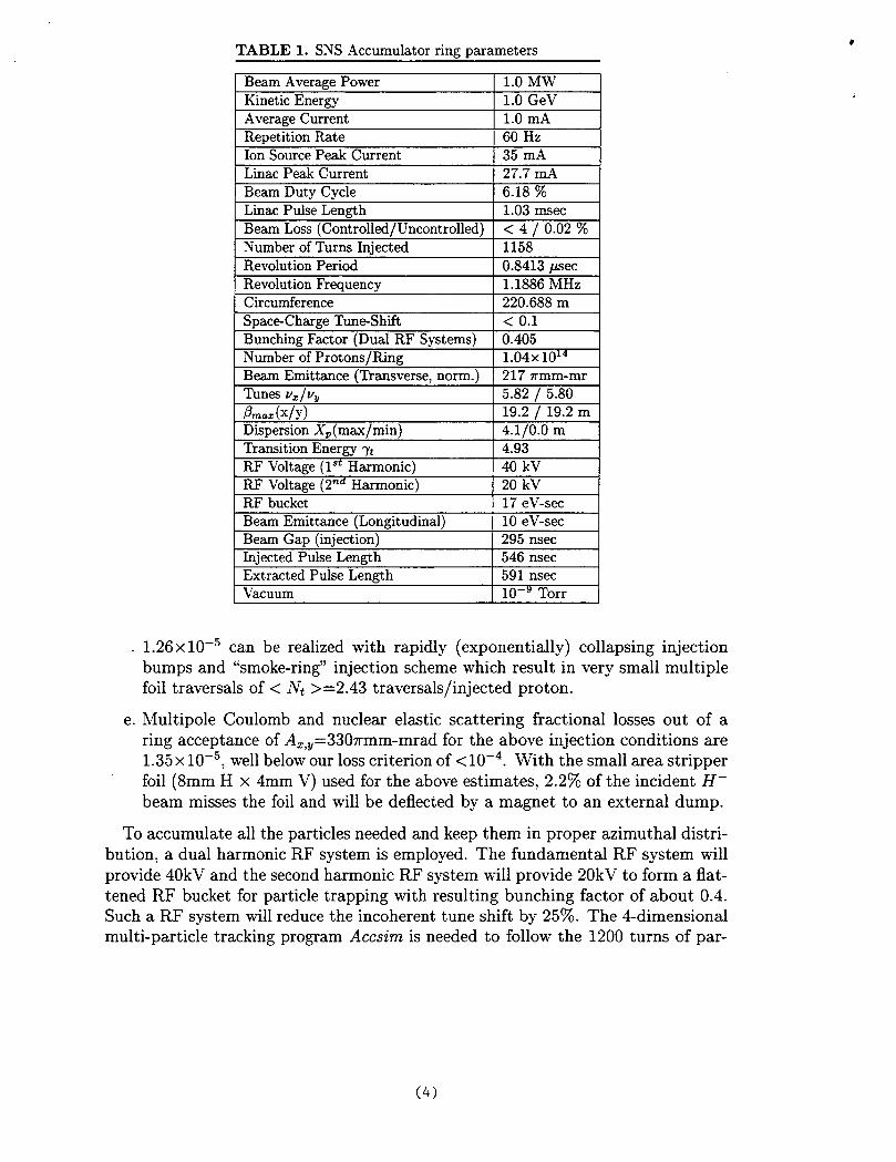
TABLE 1. SNS Accumulator riruz~arameters
e.
1.26x 10⁻⁵
Beam Average Power 1.0 MWKinetic Energy 1.0 GeVAverage Current 1.0 mARepetition Rate 60 HzIon SourcePeak Current 3=5mALinac Peak Current 27.7 rdBeam Duty Cycle 6.18 %Linac PulseLength 1.03 msecBeam Loss (Controlled/Uncontrolled) <4/0.02%Numberof Turns Injected 1158Revolution Period 0.8413 /JSeC
RevolutionFrequency 1.1886 MHzCircumference 220.688 mSpac&ChargeTune-Shift <0.1BunchingFactor (Dual RF Systems) 0.405Numberof Protons/Ring 1.04X10¹⁴Beam Emittance (’llansverse, norm.) 217 rmm-mrTunesv. Iv., 5.82 / 5.80ikz(xiib” 19.2 ~ 19.2 mDispersionX.(max/min] 4.1/0.0 m. r., ,
TransitionEnergy ~t 4.93RF Voltage (lst Harmonic) 40 kVRF Voltage (2nd Harmonic) 20 kVRF bucket 17 eV-secBeam Emittance (Longitudinal) 10 eV-secBeam Gap (injection) 295 nsecInjected PulseLength 546 nsecExtracted Pulse Length 591 nsecVacuum 10–9 Torr
can be realized with rapidly (exponentially) collapsing injectionbumps and “smoke-ring” injection scheme which result in very small multiplefoil traversals of < N~ >=2.43 traversals/injected proton.
Multipole Coulomb and nuclear elastic scattering fractional losses out of a–330rmm-mrad for the above injection conditions arering acceptance of A=,V–
1.35x 10⁻⁵, well below our loss criterion of <10-4. With the small area stripperfoil (8mm H x 4mm V) used for the above estimates, 2.2% of the incident H-beam misses the foil and will be deflected by a magnet to an external dump.
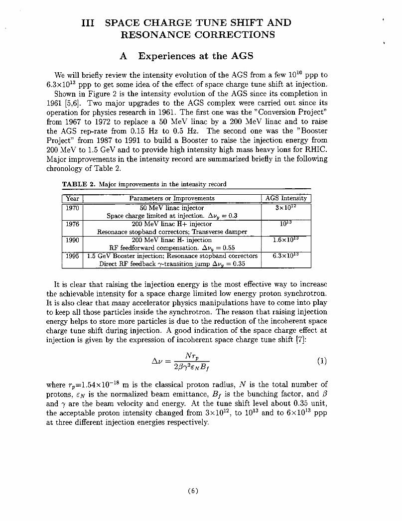
To accumulate all the particles needed and keep them in proper azimuthal distri-bution, a dual harmonic RF system is employed. The fundamental RF system willprovide 40kV and the second harmonic RF system will provide 20kV to form a flat-tened RF bucket for particle trapping with resulting bunching factor of about 0.4.Such a RF system will reduce the incoherent tune shift by 25%. The 4-dimensionalmulti-particle tracking program Accszm is needed to follow the 1200 turns of par-
(4)
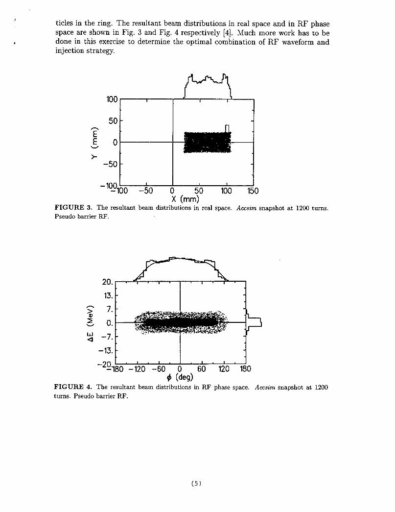
#titles in the ring. The resultant beam distributions in real space and in RF phasespace are shown in Fig. 3 and Fig. 4 respectively [4]. Much more work has to be
# done in this exercise to determine the optimal combination of RF waveform andinjection strategy.
100
50
‘?:0
>–50
E ?:– ‘~”loo -5I) o 51() 100 150
X (mm)FIGURE 3. The resultant beam distributionsin real space. Accsirn snapshot at 1200 turns.Pseudo barrierRF.
20.
13. -
z
u4
–13. -I 1 1 I
‘2%80 -120 -60 0 60 120 180# (deg)
FIGURE 4. The resultant beam distributionsin RF phase space. Accsinz snapshot at 1200turns. Pseudo barrier RF.
(5:)
III SPACE CHARGE TUNE SHIFT ANDRESONANCE CORRECTIONS
A Experiences at the AGS
We will briefly review the intensity evolution of the AGS from a few 1010 ppp to6.3 x1013 ppp to get some idea of the effect of space charge tune shift at injection.
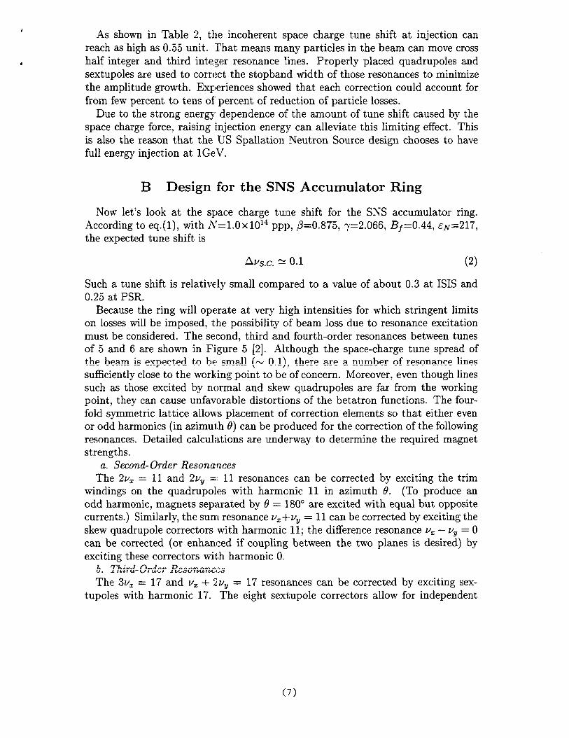
Shown in Figure 2 is the intensity evolution of the AGS since its completion in1961 [5,6]. Two major upgrades to the AGS complex were carried out since itsoperation for physics research in 1961. The first one was the “Conversion Project”from 1967 to 1972 to replace a 50 MeV Iinac by a 200 MeV linac and to raisethe AGS reprate from 0.15 Hz to 0.5 Hz. The second one was the “BoosterProject” from 1987 to 1991 to build a Booster to raise the injection energy from200 MeV to 1.5 GeV and to provide high intensity high mass heavy ions for RHIC.Major improvements in the intensity record are summarized briefly in the followingchronology of Table 2.
TABLE 2. Major improvementsin the intensity record
Year Parameters or Improvements AGS Intensity
1970 50 MeV linac injector 3X10¹²Space charge limited at injection. AvY = 0.3
1976 200 MeV linac H+ injector 1013Resonance stopband correctors; Transversedamper
1990 200 MeV Iinac H- injection 1.6x101JRF feedforward compensation. AuY = 0.55
1995 1.5 GeV Booster injection; Resonance stopband correctors 6.3x10¹³Direct RF feedback ~-transition jump AVY= 0.35
It is clear that raising the injection energy is the most effective way to increasethe achievable intensity for a space charge limited low energy proton synchrotrons.It is also clear that many accelerator physics manipulations have to come into playto keep all those particles inside the synchrotrons. The reason that raising injectionenergy helps to store more particles is due to the reduction of the incoherent spacecharge tune shift during injection. A good indication of the space charge effect atinjec~ion is given by th~ ex-pression of;ncoherent
Av =NrP
2~~2Ep/Bf
space charge tune shift [7]:
(1)
where rP=l .54x 10–18 m is the classical proton radius, N is the total number ofprotons, EN is the normalized beam emittance, Bf is the bunching factor, and @and ~ are the beam velocity and energy. At the tune shift level about 0.35 unit,the acceptable proton intensity changed from 3x10¹², to 1013 and to 6x10¹³ pppat three different injection energies respectively.
(6)
As shown in Table 2, the incoherent space charge tune shift at injection canreach as high as 0.55 unit. That means many particies in the beam can move crosshalf integer and third inte:ger resonance lines. Properly placed quadruples andsextuples are used to correct the stopband width of those resonances to minimizethe amplitude growth. Experiences showed that each correction could account forfrom few percent to tens of percent of reduction of particle losses.
n.. - 4A +Le .+=---- ---, Jn--. dhn-hn-c LLA-- A..-+ -c +---- .I.:CA ,-..,a,a k.. +LAUuu UJ IJllc a blullg Cllcn by Ucpcxlualw UJ. (JUG CM1lUULIIJ U1 IJullc Dllllu LCluixu Uy (I1lC
space charge force, raising injection energy can alleviate this limiting effect. Thisis also the reason that the U-S Spaiiation N-eutron Source design chooses to havefull energy injection at lGeV.
B Design for the SNS Accumulator Ring
Now let’s look at the space charge tune shift for the SNS accumulator ring..According to en (1\ with ~—1 nX 1014 ~pll, p=~.f375, ~=2.0~q Bf=0.44, ~F:=217,--1-\-)7 .. —- ------the expected tune shift is
Av~.c. z 0.1 (2)
Such a tune shift is relatively small compared to a value of about 0.3 at ISIS andnnr -L nonU.AO aL rrn.
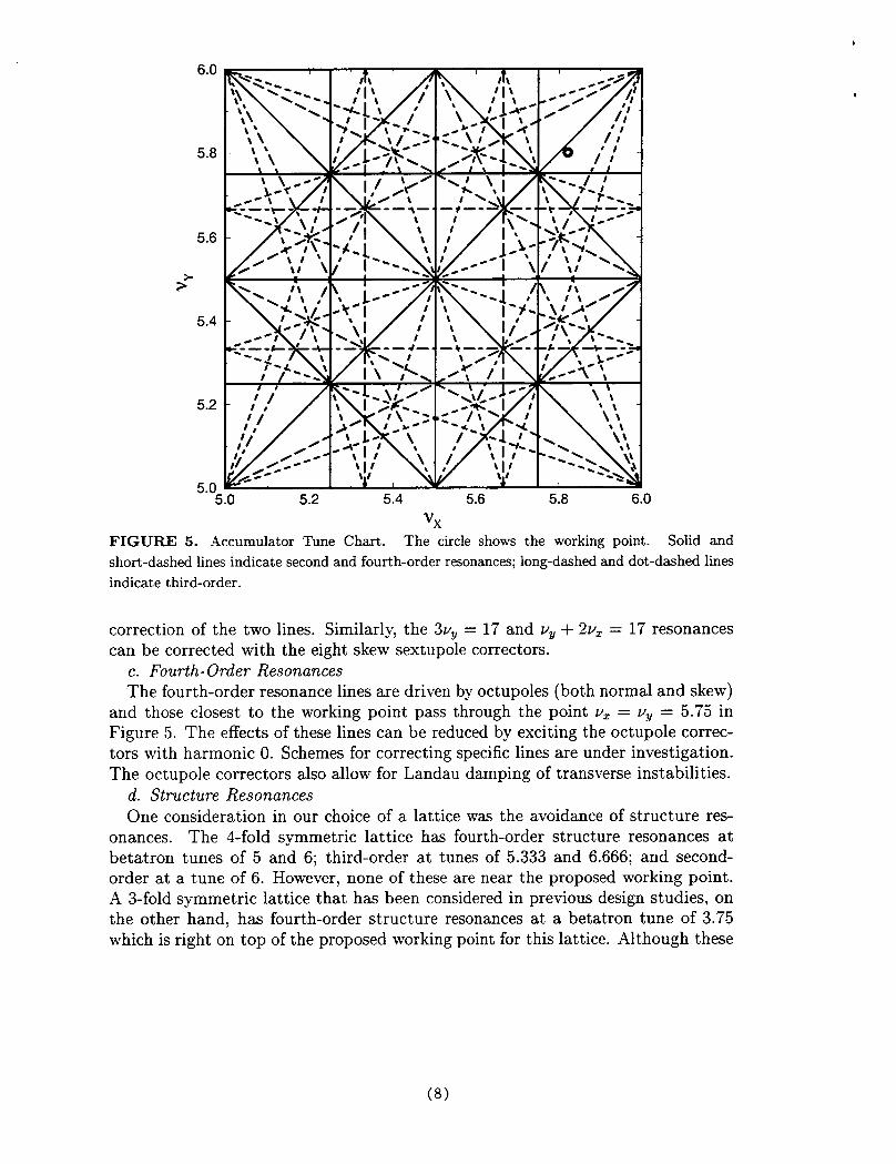
Because the ring will operate at very high intensities for which stringent limitson losses will be imposed, the possibility clf beam loss due to resonance excitationmust be considered. The second, third and fourth-order resonances between tunesof 5 and 6 are shown in Figure 5 [2]. Although the space-charge tune spread ofthe beam- is expected to he’ srn_a!] (N n. I )> there ~r~ ~ number Qf r~sonanc~ !ines
sufficiently close to the working point to be of concern. Moreover, even though lines,...- .-...,.:A-d 1.... -...—--1 .-.-4 “1----- . ...--1..- --- CA-C-A—+La .....-1.....->Uukl as those CXLIIXU U,y llU1 lllrll CIJlu Wiu w qiiadl Upulm CLLC lCL1 11 Ulll IJllc Wul rull~
point, they can cause unfavorable distortions of the betatron functions. The four-fold symmetric iattice aiiows piacement of correction elements so that either evenor odd harmonics (in azimuth 0) can be prc)duced for the correction of the followingresonances. Detailed calculations are underway to determine the required magnetstrengths.
a. Second-Order Resonances1=1.a9., 11 --A 9., =: 11 -n”c,-av,r.ac!C.mnAn mn..,v.+,dL., ,mrc.;+; nm +Imfi +AmL llC L1/z = J. L a’llu Awy 1 J. 1 CCNJ1l@lltJCil LcX1l UC UU11 CL IJCU UJ GAL1 lJU1~ LJ1lC UL 1111
windings on the quadruples with harmonic 11 in azimuth O. (To produce anodd harmonic, magnets separated by 6 = 1W are excited with equal but opposite
---0
currents.) Similarly, the sum resonance v=-t-vV= 11 can be corrected by exciting theskew quadruple correctors with harmonic 11; the difference resonance VZ– Vy= Ocan be corrected (or enhanced if coupling between the two planes is desired) byexciting these correctors with harmonic O.
k frh;PA nm~.a. Dn..,nr.a-.... n1 IGbIu-w IwcI JbGauIbuI*L(;a~he 3VZ = 17 and v. + 2VY= 17 resonances can be corrected by exciting sex-
tupoies with harmonic 1“7. The eight sextupoie correctors aiiow for independent
(:7)
6.0
5.8
5.6
>>
5.4
5.2
“.”
5.0 5.2 5.4 5.6 5.8 6.0
Vx
FIGURE 5. .Accumulator Tune Chart. The circle shows the working point. Solid andshort-dashed lines indicate second and fourth-order resonances;long-dashedand dot-dashed linesindicate third-order.
correction of the two lines. Similarly, the 3VY= 17 and Vy + 2VZ = 17 resonancescan be corrected with the eight skew sextupole correctors.
c. Fourth-Order ResonancesThe fourth-order resonance lines are driven by octupoles (both normal and skew)
and those closest to the working point pass through the point v~ = VY= 5.75 inFigure 5. The effects of these lines can be reduced by exciting the octupole correc-tors with harmonic O. Schemes for correcting specific lines are under investigation.The octupole correctors also allow for Landau damping of transverse instabilities.
d. Structure Resonances
One consideration in our choice of a lattice was the avoidance of structure res-onances. The 4-fold symmetric lattice has fourth-order structure resonances atbetatron tunes of 5 and 6; third-order at tunes of 5.333 and 6.666; and second-order at a tune of 6. However, none of these are near the proposed working point.A 3-fold symmetric lattice that has been considered in previous design studies, onthe other hand, has fourth-order structure resonances at a betatron tune of 3.75which is right on top of the proposed working point for this lattice. Although these
(8)
1
resonances may not hurt the ring performance, they are best avoided.
,IV HALO FORMATION AND COLLIMATION
One of the major performance requirements of the SNS ring is to keep the averageuncontrolled particle loss cluring the accumulation time to less than 2.0x 10⁻⁴ perpulse. The reason of this smingent requirement is to keep the residual radiation tosuch a level that the hands-on maintenance is possible except for a few localizedareas, such as: injection, extraction and collimation.
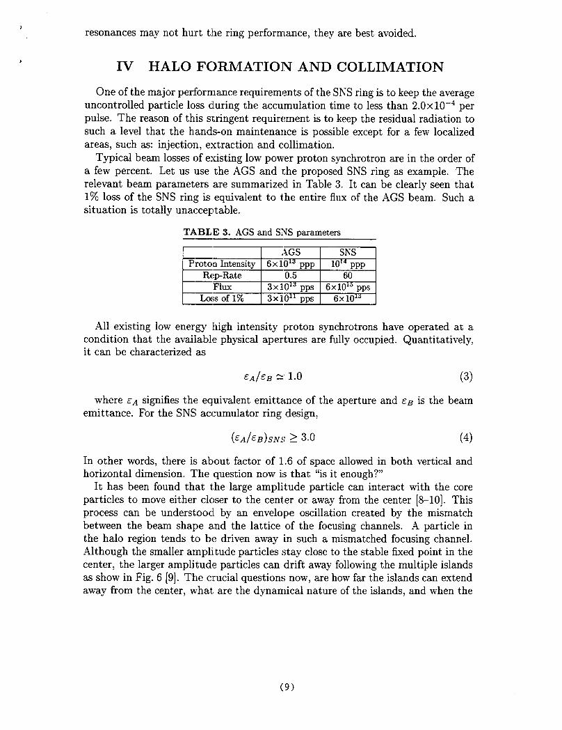
Typical beam losses of existing low power proton synchrotrons are in the order ofa few percent. Let us use the AGS and the proposed SNS ring as example. Therelevant beam parameters are summarized in Table 3. It can be clearly seen that1% loss of the SNS ring is equivalent to the entire flux of the AGS beam. Such asituation is totally unacceptable.
TABLE 3. AGS and SINSparameter
ESEE!EIAll existing low energy high intensity ,proton synchrotrons have operated at a
condition that the available physical apertures are fully occupied. Quantitatively,it can be characterized as
EA/EB % 1.0 (3)
where CA signifies the equivalent ernittance of the aperture and ~B is the beamemittance. For the SNS accumulator ring design,
(&J&~)~~~ >3.0
In other words, there is about factor of 1.6 of space
(4)
allowed in both vertical andhorizontal dimension. The question now is that ~’isit enough?”
It has been found that the large amplitude particle can interact with the coreparticles to move either clc~ser to the center or away from the center [8-10]. Thisprocess can be understood by an envelope oscillation created by the mismatchbetween the beam shape a,nd the lattice of the focusing channels. A particle inthe halo region tends to be driven away in such a mismatched focusing channel.Although the smaller amplitude particles stay close to the stable fixed point in thecenter, the larger amplitude particles can drift away following the multiple islandsas show in Fig. 6 [9]. The c:rucial questions now, are how far the islands can extendaway from the center, what are the dynamical nature of the islands, and when the
(9)
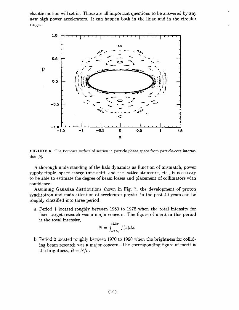
chaotic motion will set in. Those are all important questions to be answered by anynew high power accelerators. It can happen both in the linac and in the circularrings.
1.0
1“’’’’’’’’’’’’’’’’’’’’’’’’’”!
P
0.5
0.0
-0.5
0--:. --00s .- . *,
-a/. \/- -..--- . ---- . --
/e- e.~o--k-~ .*6 a
... ~ -... . ... . . . ..%“.
0J
-1.0 L 1 , I 1 1,, , ,1,,,,1,,,,1.,,,,1,,, ,:-1.5 -1 -0.5 0 0.5 1 1.5
x
FIGURE 6. The Poincare surface of section in particle phase space from particl~core interac-tion [9].
A thorough understanding of the halo dynamics as function of mismatch, powersupply ripple, space charge tune shift, and the lattice structure, etc., is necessaryto be able to estimate the degree of beam losses and placement of collimators withconfidence.
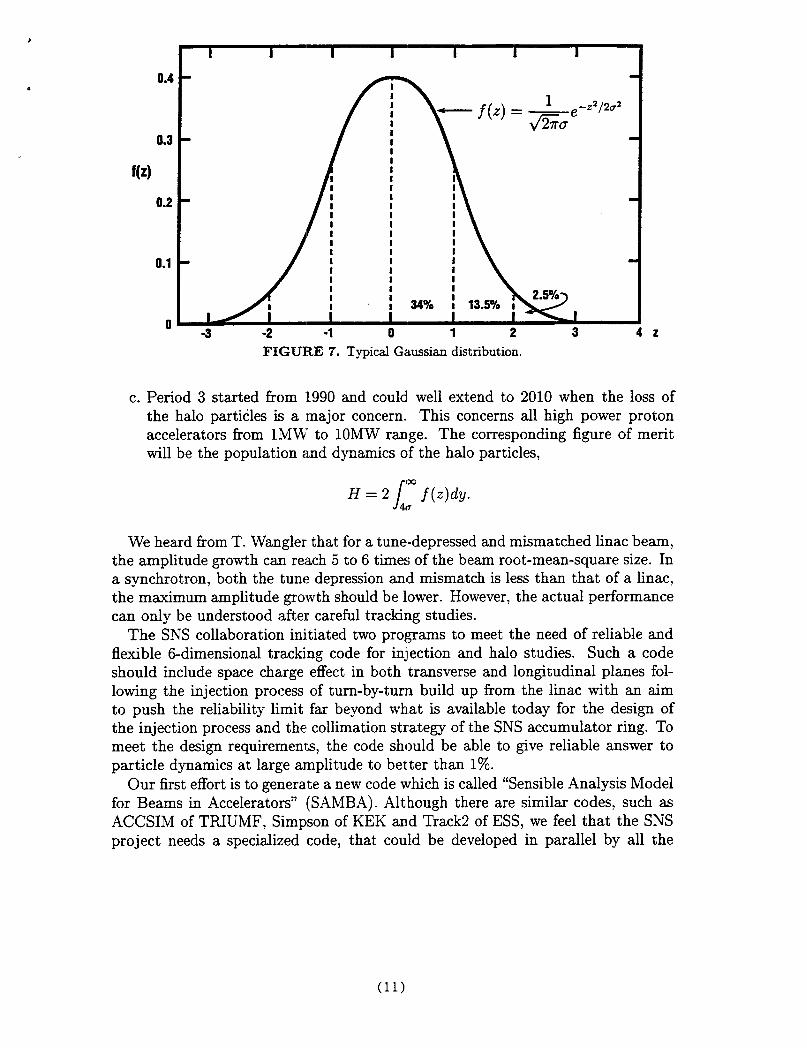
Assuming Gaussian distributions shown in Fig. 7, the development of protonsynchrotrons and main attention of accelerator physics in the past 40 years can beroughly classified into three period.
a.
b.
Period 1 located roughly between 1960 to 1975 when the total intensity forfixed target research was a major concern. The figure of merit in this periodis the total intensity,
N= f:; f(.)d..
Period 2 located roughly between 1970 to 1990 when the brightness for collid-ing beam research was a major concern. The corresponding figure of merit isthe brightness, B = N/a.
(lo)
0.4
0.3
f(z)
0.2
0.1
0
.
.
.
-22/202
k’
9,//1.l.,’11\5..-3 -2 -1 0 1 2 3 42
FIGU13,13 7. Typical Gaussian distribution.
c. Period 3 started from 1990 and could well extend to 2010 when the loss ofthe halo particles is a major concern. This concerns all high power protonaccelerators from lNIWI’ to 10MW range. The corresponding figure of meritwill be the population and dynamics of the halo particles,
H=2/: f(z)dy.
We heard from T. Wangler that for a tune-depressed and mismatched linac beam,the amplitude gowth can reach 5 to 6 times of the beam root-mean-square size. Ina synchrotrons, both the tune depression and mismatch is less than that of a Iinac,the maximum amplitude growth should be lower. However, the actual performancecan only be understood after careful tracking studies.
The SNS collaboration initiated two programs to meet the need of reliable andflexible 6-dimensional tracking code for injection and halo studies. Such a codeshould include space charge effect in both transverse and longitudinal planes fol-lowing the injection process of turn-by-turn build up from the Iinac with an aimto push the reliability limit far beyond what is available today for the design ofthe injection process and the collimation strategy of the SNS accumulator ring. Tomeet the design requirements, the code should be able to give reliable answer toparticle dynamics at large amplitude to better than 1%.
Our first effort is to generate a new code which is called “Sensible Analysis Modelfor Beams in Accelerators” (SAMBA). Although there are similar codes, such asACCSIM of TRIUMF, Simpson of KEK and Track2 of ESS, we feel that the SNSproject needs a specialized code, that could be developed in parallel by all the
(11)
members of the joint team, and is more comprehensive than existing codes, yetdevoid of things that are not so important for our project. In doing so, we havefreely borrowed from other codes we know, trying to collect the best in each oneof them. We report the development of simulation codes by the joint team. Thesalient feature of this new code is summarized in the following [1I].
SAMBA is written in C++. We did this for two main reasons:
. development of programming modules in parallel is more natural with C++than with Fortran. This is why C++ has become the standard in the Industry,where a large group of programmers are often working on the same code, tobring it as early as possible to the market.
● the code is run under the supervision of a SuperCode that allows the coexis-
tence of compiled and interpreted modules, making development and debbug-ing very natural, as it will be explained later in detail.
the machine optics code that produces the main accelerator descriptor is MAD.This is a well developed and maintained code able to describe all of the features ofthe ring lattice, including higher order transformation matrices and the treatmentof lattice errors.
SAMBA is independent from any specific graphic packages. Output to graphicscan be done through files or by direct pipe from the code to graphics, in order toallow for animation. An intriguing possibility is to use the graphic firmware toolsof the workstation to perform some of the calculations.
The real beam is represented by an ensemble of macro-particles in fully 6-dimensional phase space. The calculations include:
a. transport of the particles in the lattice using the first order and second ordertransformations calculated by MAD.
b. in the transverse space, space charge forces are calculated that apply an an-gle kick to the macros. Betatron tune distribution in the beam is calculated(“necktie” ). Transverse impedances are used to calculate beam to wall cou-pling in a realistic vacuum chamber geometry.
c. in the longitudinal space, we have cavities with RF voltage plus a realisticlongitudinal impedance budget, that allows the representation of longitudinalspace charge kicks and the description of the bunch and the bucket.
Most of our design work on SNS injection and RF stacking has been performedusing SAMBA. Work is continuing to complete this code development.
Since the most crucial physics input in this tracking code is the treatment ofspace charge force, to save time, some kind of approximations are always made.Such a simplified approach is necessary in comparing one scenario from another.However, its accuracy has to be checked by more reliable approach. To establisha benchmark for simplified treatment and establish accuracy of the calculation wecreate a particle in cell (PIC) module for space charge calculation.
(12)
Previous injection calculations for the SNS have employed the Schonauermodel [12] for transverse space charge effkcts, which are limited to shifting thethe macro-particle tunes. No other space charge effects on the transverse spatialcharge distributions are calculated in this model. As such, to date the final ringemittance is determined by the choice of the linac beam distribution, by the closedorbit bumps, and by scattering of the beam by the foil. In this model only foilinteractions produce beam halo. Here, preliminary results are reported using a fullParticle-In-Cell (PIC), space charge calculation [13] for SNS injection. The impactof transverse space charge on emittance growth and halo are examined by repeat-ing the previous Schonauer model optimizeci injection scenarios, here using the PICmodel. Although the initial operation of the SNS will be at 1.OMW of beam power,these calculations are done for 2.OMW of beam power, since the ring is designed toallow for the 2.OMW upgrade.
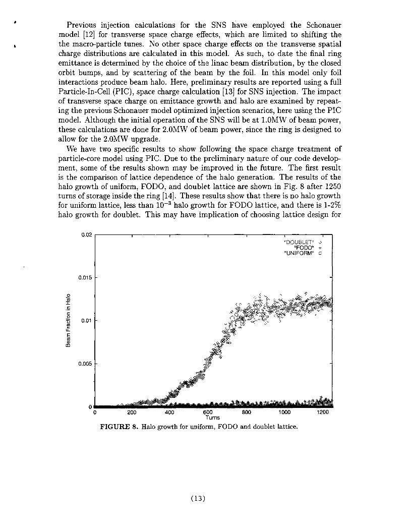
We have two specific results to show following the space charge treatment ofparticle-core model using PIC. Due to the preliminary nature of our code development, some of the results shown may be improved in the future. The first resultis the comparison of lattice dependence of the halo generation. The results of thehalo growth of uniform, FODO, and doublet lattice are shown in Fig. 8 after 1250turns of storage inside the ring [14]. These results show that there is no halo growthfor uniform lattice, less than 10-3 halo growth for FODO lattice, and there is 1-2%halo growth for doublet. This may have implication of choosing lattice design for
.y-)J&J&~:: ~
“FODO” +“UNIFORM” G
0.015 -
0.01
0.005 -
oL~o 200 400 600 800 1000 1200
Turns
FIGURE 8. Halo growth for uniform, FODO and doublet lattice.
(13)
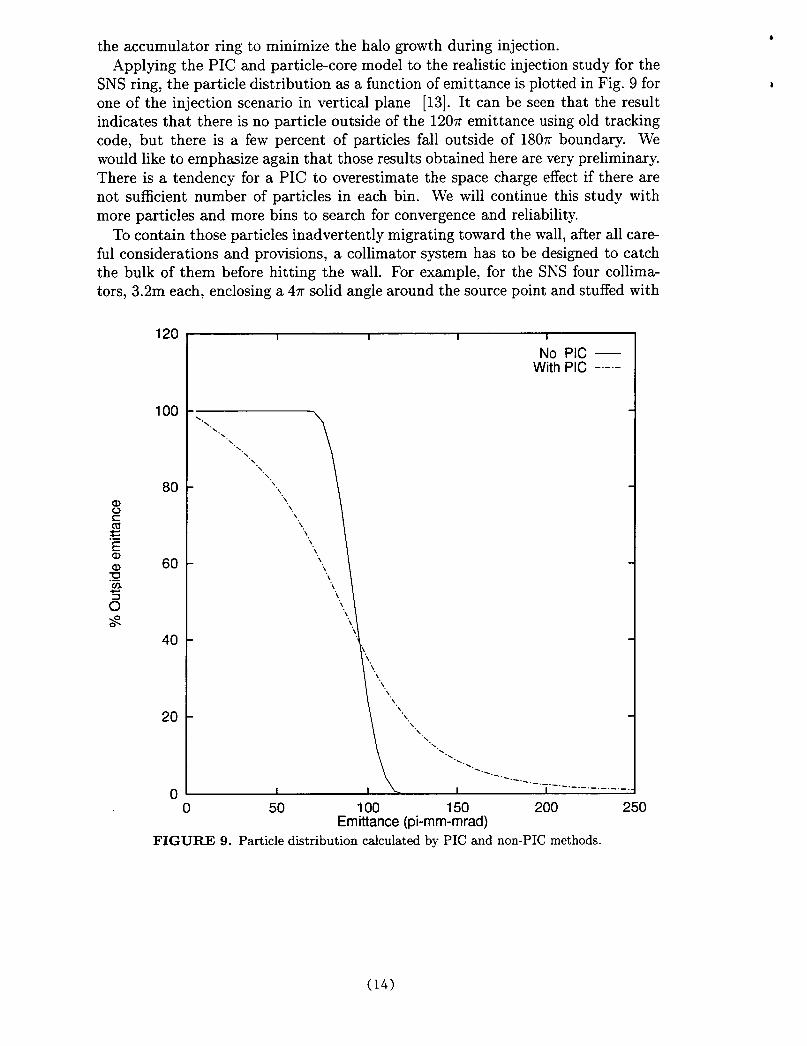
the accumulator ring to minimize the halo growth during injection.Applying the PIC and particle-core model to the realistic injection study for the
SNS ring, the particle distribution as a function of emittance is plotted in Fig. 9 forone of the injection scenario in vertical plane [13]. It can be seen that the resultindicates that there is no particle outside of the 1207r emittance using old trackingcode, but there is a few percent of particles fall outside of 1807r boundary. Wewould like to emphasize again that those results obtained here are very preliminary.There is a tendency for a PIC to overestimate the space charge effect if there arenot sufficient number of particles in each bin. We will continue this study withmore particles and more bins to search for convergence and reliability.
To contain those particles inadvertently migrating toward the wall, after all care-ful considerations and provisions, a collimator system has to be designed to catchthe bulk of them before hitting the wall. For example, for the SNS four collima-tors, 3.2m each, enclosing a 47r solid angle around the source point and stuffed with
120
100
80
60
40
20
0
No PIC —With PIC ---
~.~.~.~.,. ,.~.,
“\.\
“\‘\,
\,\,
\‘\
‘\‘\‘\,\‘\,\,\‘\“\“\,
\,\
-----------
------- ------- ._ .- ._.
o 50 100 150 200 250Emittance (pi-mm-mrad)
FIGURE 9. Particle distribution calculated by PIC and non-PIC methods.
(14)
segmented material to capture all secondary particles generated by the incident pro-tons will be provided to reduce the radiation effects by a factor of 100. This w’ay,most of uncontrolled losses will occur at the collimator, leaving ring componentsrelatively intact for reliable operation [15].
For the SNS ring, the beam emittance is 120T and the physical acceptance is360T. The hard decision is where to put the collimator? The possibility could bearound 2207r to 260n. The good answer can only be provided by the results froma reliable tracking code incorporating full space charge effects. We will continue towork in this direction to find satisfactory solution for SNS. One way to minimizethe particle interception by the collimator is to introduce bend crystal upstream ofthe collimator to bring large amplitude particles outside of the accumulator ring.Depending on the final strategy adopted, the collimator will take a few percent toa few tenth of a percent beam losses and should be able to sustain direct hit of fullbeam for few pulses. With the help from this workshop, we will incorporate all thegood ideas suggested to improve on the SNS design.
V ACKNOWLEDGEMENT
The report given here is the results of both AGS and SNS accelerator physicsstaff. Contributions by J. 13eebe-Wang, M. Brennan, J. Galambos, C. Gardner,J. Holmes, S.Y. Lee, Y.Y. Lee, A. Luccic~, and D. Olsen are appreciated. Theauthor would also like to thank J. Beebe-Wang for preparing this manuscript forpublication.
1.
2.
3.
4.
5.
6.
7.
REFERENCES
~.~. Weng, et al., “Accumulator Ring Design for the NSNS Project”, contributedpaper to PAC97, May 12-16, 1997, Vancover, Canada.Y.Y. Lee, C.J. Gardner i~nd A.U. Luccio: “Accelerator Ring Lattice for the Na-tional Spallation Neutron Source”, contributed paper to PAC97, May 12-16, 1997,Vancover, Canada.L.N. Blumberg and Y.Y. I,ee: “n- Charge Exchange Injection Into the lGeV NSNSAccumulator”, BNL/NSNS Tech. Note #3, November, 1996.A.U. Luccio, J. Beebe-Wang and D. Maletic: “Proton Injection and RF Capture inthe National Spallation Neutron Source”, contributed paper to PAC97, May 12-16,1997, Vancover, Canada.W.T. Weng, “Performance and Measurements of the AGS and Booster Beams”, AIPConf. Proc. No.377, p.145, Bloomington, [N, Oct. 10-13, 1995.T. Roser: “High Intensity Performance and Upgrades at the Brookhaven AGS”, inthese workshop proceedings.L.J. Laslett: “On Intensity Limitations Imposed by Transverse Space-Charge Effectsin Circular Particle Accumulators”, BNL Report 7534, p.32467, 1963.
(15)
8.
9.
10.
11.
12
13
14
15
R.A. Jameson, “Self-Consistent Beam Halo Studies and Halo Diagnostic Development”, Frontiers oj Accelerator Z’echnologg, World Scientific, p.530, November, 1994.S.Y. Lee and A. Riabko, “Envelop Hamiltonian of an Intense Charged-Particle Beamin Periodic Solenoidal Fields”, Phys. Rev. E, VO1.51,Feb., 1995.T. Wangler, “Space Charge in Proton Linacs” , in these workshop proceedings.A.U. Luccio, J. BeebeWang, M. Blaskiewicz, J. Galambos, J. Holmes and D. Olsen,“A Particle Simulation Code for a High Intensity Accelerator Ring”, in these work-shop proceedings.H. Schonauer, “Addition of Transverse Space Charge to ACCSIM Code”, TriumfDesign Note TRI-DN-89-K50.J. Galambos, J. Holmes, D. Olsen, J. Whealton, M. Blaskiewicz, A. Luccio andJ. Beeb&Wang, “Progress Towards Understanding Transverse Space Charge Effectson SNS Ring Injection”, in these workshop proceedings.J.A. Holmes, J.D. Galambos, J.H. Whealton, D.K. Olsen, M. Blaskiewicz, A. Luccio,J. Beeb~Wang and S.Y. Lee, “Space Charge Calculations in Rings for Uniform,FODO, and Doublet Lattice”, in these workshop proceedings.H. Ludewig, S. Mughabghab and M. Todosow, “NSNS Ring System Design Study,Collimation and Shielding”, BNL/SNS Tech. Note No.5, 1996.
(16)
Related Documents