University of Miskolc Institute of Information Science Department of Information Technology Faculty of Mechanical Engineering and Informatics SNMP-MIB dataset – Generating and Classification of DDoS Master thesis Author: Raja’ Yousef Hayajneh Registration code: NTICL8 Address 2019

Welcome message from author
This document is posted to help you gain knowledge. Please leave a comment to let me know what you think about it! Share it to your friends and learn new things together.
Transcript
University of Miskolc
Institute of Information Science
Department of Information Technology
Faculty of Mechanical Engineering and Informatics
SNMP-MIB dataset – Generating and
Classification of DDoS
Master thesis
Author: Raja’ Yousef Hayajneh
Registration code: NTICL8
Address
2019

1
University of Miskolc
Faculty of Mechanical
Engineering and Informatics
Department of
Information Technology
Miskolc-Egyetemváros, 3515
Hungary
Major: Computer Science and
Engineering
Thesis number:
IAL/NTICL8/MSc/2019
Level: Master National Uni. Id.: FI 87515
THESIS SPECIFICATION
Raja’ Yousef Hayajneh
Registration code: NTICL8
Candidate for MSc degree in Computer Science and Engineering
Subject of thesis: Computer Networks
Title of thesis: SNMP-MIB dataset - Generating and Classification of
DDoS
Detailed specification:
Introduce the architecture of the Simple Network Management Protocol
(SNMP).
Discuss the basic concepts of the Intrusion Detection System (IDS)
methodologies with respect to the SNMP based solutions
Set up a testbed network for collecting SNMP related data in case of attack
events.
Collect SNMP data from the network and identify the intrusion events.
Supervisor:
Szilveszter Kovács, PhD.
Affiliation, position:
Associate Professor, University of Miskolc
Consultant:
Almseidin Mohammad Abdallah Suleiman
Affiliation/company, position:
PhD Student, University of Miskolc
Date of issue: 15. February 2019.
Deadline for submission: 3. May 2019.
Miskolc, 15. February 2019.
Dr. Kovács, László
Head of Department

2
1. Place of practice field: ________________________________________
2. Supervisor of practice field: _______________________________________
3. Modifications to the thesis: required (should be attached separately)
not required (underline as appropriate)
Miskolc, _____________ Supervisor
4. Dates of consultation: (1)___________________________________
(2)___________________________________
(3)___________________________________
(4)___________________________________
Date Supervisor/Consultant
5. Thesis submission: accepted / not accepted (underline as appropriate)
Miskolc, _____________
Consultant Supervisor
6. Thesis contains: ...… pages,
...… appendices,
...… CD attachment,
...… other attachment.
7. Thesis: approved / not approved (underline as appropriate)
Name and affiliation of Opponent: _________________________________
Miskolc, _____________
Head of Department
8. Grades: Opponent: ____________________________________
Department: ___________________________________
Final Examination Board: ________________________
Miskolc, _____________ Chairman of FEB

1
Declaration of Authorship
I, Raja’ Yousef Hayajneh, Neptun code: NTICL8, MSc student of the Faculty of Mechanical
Engineering and Informatics, University of Miskolc, being acutely aware of my legal liability,
hereby confirm, declare and certify with my signature, that the assignment, entitled “SNMP-
MIB dataset - Generating and Classification of DDoS” - except where indicated by referencing -
, is my own work, is not copied from any other person’s work, and is not previously submitted
for assessment at University of Miskolc or elsewhere, and all sources (both the electronic and
printed literature, or any kind) referred to in it, have been used in accordance with the rules of
copyright.
I understand that a thesis work may be considered to be plagiarized if it consists of
- Quoting word by word or referring to literature either with no quotation
marks or no proper citation;
- Referring to content without indicating the source of reference; -
Representing previously published ideas as one’s own.
I, hereby declare that I have been informed of the term of plagiarism, and I understand that in the
case of plagiarism my thesis work is rejected.
Miskolc, 16 (day) May (month) 2019(year)
------------------------------------------------
Student’s signature

2
ACKNOWLEDGMENTS
I would like to express my sincere thanks and gratitude to my supervisor, Dr. Mohammad
Abdallah Almseidin for his priceless help, encouragement, support and constructive comments
throughout the preparation of this thesis.
I would like also to thank Ass. Prof Szilveszter Kovac for his cooperation during my thesis. I
would like to extend my thanks to the Tempus Foundation (Stipendium Hungaricum
Scholarship) program for offering me a scholarship and covering all the funds of my master.
This dissertation is dedicated to my family, especially my father and my mother who always
have faith in me.
Finally, I would like also to dedicate this work to everyone has a passion for learning
Information technology.

3
TABLE OF CONTENTS
ACKNOWLEDGEMENTS ..................................................................................... ..................... I
LIST OF FIGURES and TABLES.............................................................................................. IV
LIST OF ABBREVIATIONS ...................................................................................................... V
ABSTRACT ................................................................................................................................. V
CHAPTER ONE: INTRODUCTION .......................................................................................... 3
Theoretical Background ................................................................................................................3
Motivation .................................................................................................................................... 3
Contribution of this Thesis ............................................................................................................4
Background .................................................................................................................................. 4
CHAPTER TWO: LITERATURE REVIEW .............................................................................. 5
Simple network management protocol …......................................................................................5
The SNMP Architecture ............................................................................................................... 7
SNMP MIB …............................................................................................................................... 7
SNMP OID …............................................................................................................................... 8
Goals of the Architecture ............................................................................................................. 9
Literature review ………............................................................................................................. 11
CHAPTER THREE: DESIGN AND METHODOLOGY .......................................................... 21
Intrusion Detection System ......................................................................................................... 21
Attacks ........................................................................................................................................ 23
IDS Classifier MLP-ANN………........................................................................................…… 32
Random Forest ..................................................................................................................……...35
Naïve Bayes ................................................................................................................................ 36
Waikato Environment for Knowledge Analysis (WEKA) ..................................................……37
CHAPTER FOUR: FINDINGS, DISCUSSION AND RECOMMENDATIONS ..................... 48
Experimental Set-up ............................................................................................................……48
Results ................................................................................................................................……..51
CHAPTER FIVE: CONCLUSION AND FUTURE WORK ......................................................53
Conclusion..............................................................................................................................…...53
REFERENCES .............................................................................................................................58

4
LIST OF FIGURES:
Figure1: SNMP.........................................................................................................................6
Figure 2: SNMP process...........................................................................................................8
Figure 3: MIB process .............................................................................................................17
Figure 4: NIDS and HIDS........................................................................................................22
Figure 5: Normal contact .........................................................................................................24
Figure 6: SYN flood ................................................................................................................24
Figure 7: ICMP – ECHO attack............................................................................................... 25
Figure 8: ICMP – ECHO attack 2 ............................................................................................26
Figure 9: DNS attack ................................................................................................................27
Figure 10: Network topology ...................................................................................................30
Figure 11 Transfer Functions................................................................................................... 32
Figure 12: Transfer Function with MLP. ................................................................................ 33
Figure 13: WEKA Explorer Panel. ......................................................................................... 39
Figure 14: WEKA OUTPUT. ..................................................................................................40
Figure 15: MLP Parameters. ....................................................................................................42
Figure 16: Random Forest Parameters. ....................................................................................44
Figure 17: Naïve Bayes Parameters. ........................................................................................44
Figure 18. Screenshot of Running UDP Attack. ......................................................................48
Figure 19. Screenshot of Running TCP Attack. ...................................................................... 48
Figure 20: Screenshot of Running ICMP Attack. ................................................................... 49
Figure 21: Average Accuracy Rate. .........................................................................................52
Figure22: False Positive Rate........................................................................................................57
Tables:
Table 1: Attack types and the corresponding tools used. ..................................... 30
Table 3.1: MLP Parameters Description ................................................................ 41
Table 3.2: MLP Parameters Values. ........................................................................ 41
Table 3.3: Random Forest Parameter Description. ............................................... 43
Table 3.4: Random Forest Parameter Values. ...................................................… 43
Table 3.5: Naïve Bayes Parameter Description. .................................................... 44
Table 3.6: attacks records ..........................................................................................51
1
LIST OF ABBREVIATIONS
AA Average Accuracy
ANN Artificial Neural Network
CSV Comma Separated Value
DDoS Distributed Denial of Service
DNS Domain Name System
HIDS Host Intrusion Detection System
ICMP Internet Control Message Protocol
IDS Intrusion Detection Systems
IIS Internet Information Service
IP Internet Protocol
KDD Knowledge Discovery in Databases
MLP Multilayer Perceptron
NB Naïve Bayes
NIDS Network Intrusion Detection System
NS2 Network Simulator Version 2
OSI Open Systems Interconnection
RMSE Root Mean Squared Error
SIDDOS Simple Query Language Injection Distributed Denial of Service
SSL Secure Socket Layer
SVM Support Vector Machine
SQL Simple Query Language
U2R User to Root Attack
UDP Unit Datagram Protocol
WEKA Waikato Environment for Knowledge Analysis

2
ABSTRACT
Distributed Denial of Service (DDoS) attacks are seen by users and organizations as an ongoing
challenge. The security engineer’s work at all times to maintain a service through intrusion
attacks. Intrusion-detection systems (IDS) are one of the solutions can be used to detect and
classify any abnormal behavior. In order to preserve service availability, an IDS system must be
constantly updated with the newest techniques for handling intrusion attacks.
In this thesis, we study the effects of DDoS attacks in both the network layer and application
layer. We have also created a system to collect a dataset from a controlled environment using a
network simulator. The dataset was generated through the following stages: data collecting, data
preprocessing, analyzing and classification. Unlike other datasets, the proposed dataset includes
9006 records with 19 attributes and with no duplicate records. The proposed dataset includes four
types of attacks, organized as follows: (ICMP, UDP-Flood, TCP-SYN, and DNS).
The higher number of AA means that the selected classifier is a good prediction model.
In our experiment, we have generated attacks traffic to detect the DDoS attacks and we used
WEKA software to analyse the results, we used MLP (Multi Layer Perceptron) algorithm, Naïve
Bayes and Random Forest. The MLP classifier achieved the highest average accuracy rate of
0.9798%; and the lowest (AA) for Naïve Bayes classifiers was 0.9507%. We could see that there
is no great difference between MLP with (AA) rate equal to 98.63% and random forest with
(AA) rate equal to 0.9763%.
3
CHAPTER ONE: Introduction
1.1 Theoretical Background
Information technology and electronic services have been available now for all areas of business
and industry for many years, nowadays, website services are subject to security threats that exist
on the World Wide Web (WWW) which causes users to be constantly concerned about service
availability or the safety and confidential of their information.
Such vulnerability allows hackers to disrupt website services or to gain illegal access to personal
data and information.
A Distributed Denial Service (DDoS) attack is considered one of the most harmful types of
attack, as it can affect the confidentiality, integrity and availability of network services. Attackers
may use several different techniques to disrupt service, one of which is consuming network
resources or consuming the server resources that host the user service.
Attackers consume different types of resources such as network bandwidth, CPU, memory
utilization, etc. Any consumption of these resources will increase overloading of the network
and, after a period of time, service will slow down or become unavailable to the end users.
Nowadays, therefore, Distributed Denial of Service (DDoS) attacks are considered a constant
challenge for both the system user and the organization. A security systems engineer’s work to
keep services available at all times using different security techniques.
1.2 Motivation
DDoS attacks at their most harmful could damage networks and stop web services, causing huge
financial losses for both small and enterprise businesses.
According to the Kaspersky technical report (Kaspersky, 2015), DDoS attacks cost small
businesses around $52,000, while enterprise businesses can lose over $444,000 per attack.
On February 8 2000, Amazon, Buy.com, CNN, and eBay were all hit by DDoS attacks that either
caused them to stop functioning completely or slowed them down significantly. According to
bookseller Amazon.com, its widely publicized attack resulted in a loss of $600,000 during the 10
hours it was down (Loukas & Oke, 2009).
4
1.3 Contribution of this Thesis
this thesis, we make the following
In this thesis, we make the following contributions:
(1) We illustrate the configuration and design of a real-life test-bed for generating attack traffic.
(2) We describe the SNMP-MIB statistical data collected from the designed test-bed.
(3) A total of 9006 records each consists of 34 MIB variables are made available for researchers
to test their IDS solutions.
1.4 Background
Many studies have exploited SNMP-MIB data in the early detection of network anomalies.
Various methodologies and techniques have been proposed and evaluated. Some researchers
have presented approaches based on statistical analysis of MIB data, while others have recently
utilized Machine Learning techniques to detect network attacks and other anomalies. We will
review previous related works on anomaly detection using SNMP-MIB. The first attempt to
exploit SNMP for network security is reported in Cabrera et al. [15]. They proposed a
methodology for the early detection of Distributed Denial of Service (DDoS) attacks by applying
statistical tests for causality to extract MIB variables that contain precursors to attacks. The
proposed methodology depends on using 91 MIB traffic variables from 5 groups (IP, ICMP,
TCP, UDP and SNMP) collected periodically from the target and the attacker participating in
attacks. Three types of DDoS attack (Ping Flood, Targa3 and UDP Flood) were conducted with
controlled loads in traffic. Their work has shown that it is possible to extract a precursor to a
DDoS attack using MIB traffic variables and to detect these attacks before the target is shut
down. However, in our work, we used unlike and extra types of DDoS attack and different MIB
variables, as well as, tried to investigate and injected up-to-date attacks that help researchers for
testing their techniques for detection the abnormality of the traffic.

5
CHAPTER TWO
2.1 Simple Network Management Protocol (SNMP)
Simple Network Management Protocol (SNMP) is an application-layer protocol used to manage
and monitor network devices and their functions. SNMP provides a common language for
network devices to relay management information within single- and multivendor environments
in a local area network (LAN) or wide area network (WAN). The most recent iteration of SNMP,
version 3, includes security enhancements that authenticate and encrypt SNMP messages as well
as protect packets during transit.
One of the most widely used protocols, SNMP is supported on an extensive range of hardware --
from conventional network equipment like routers, switches and wireless access points to
endpoints like printers, scanners and internet of things (IoT) devices. In addition to hardware,
SNMP can be used to monitor services such as Dynamic Host Configuration Protocol (DHCP).
Software agents on these devices and services communicate with a network management system
(NMS), also referred to as an SNMP manager, via SNMP to relay status information and
configuration changes.
While SNMP can be used in a network of any size, its greatest value is evident in large networks.
Manually and individually logging into hundreds or thousands of nodes would be extremely
time-consuming and resource-intensive. In comparison, using SNMP with an NMS enables a
network administrator to manage and monitor all of those nodes from a single interface, which
can typically support batch commands and automatic alerts. SNMP is described in the Internet
Engineering Task Force (IETF) Request for Comment (RFC) 1157 and in a number of other
related RFCs.
6
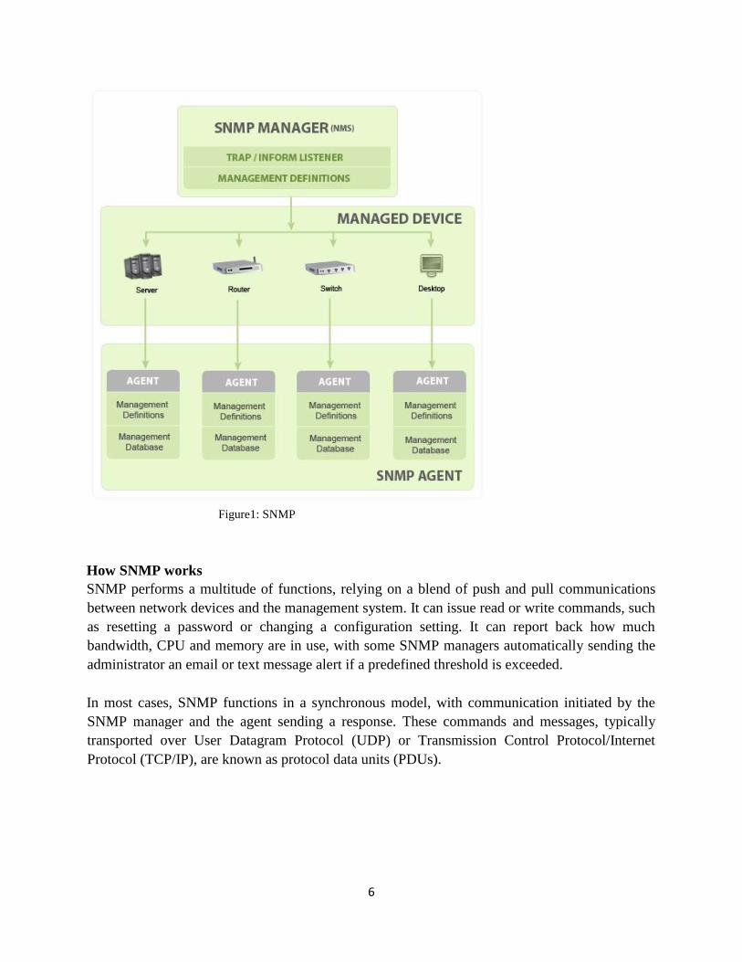
Figure1: SNMP
How SNMP works
SNMP performs a multitude of functions, relying on a blend of push and pull communications
between network devices and the management system. It can issue read or write commands, such
as resetting a password or changing a configuration setting. It can report back how much
bandwidth, CPU and memory are in use, with some SNMP managers automatically sending the
administrator an email or text message alert if a predefined threshold is exceeded.
In most cases, SNMP functions in a synchronous model, with communication initiated by the
SNMP manager and the agent sending a response. These commands and messages, typically
transported over User Datagram Protocol (UDP) or Transmission Control Protocol/Internet
Protocol (TCP/IP), are known as protocol data units (PDUs).
7
The SNMP Architecture
Implicit in the SNMP architectural model is a collection of network management stations and
network elements. Network management stations execute management applications which
monitor and control network elements. Network elements are devices such as hosts, gateways,
terminal servers, and the like, which have management agents responsible for performing the
network management functions requested by the network management stations. The Simple
Network Management Protocol (SNMP) is used to communicate management information
between the network management stations and the agents in the network elements.
SNMP MIB:
MIB stands for Management Information Base and it is a collection of hierarchically organized
information used to collect and manage definite entities from a centralized location on a remote
device. You can access these using a protocol like SNMP. Two types of MIBs exist: scalar and
tabular.
Scalar objects define one instance of objects while tabular objects set out multiple related
instances of objects, grouped into MIB tables.
MIBs are definition collections that define the properties of the managed object within the
device.
MIB Example: The typical objects to monitor on a switch of interest are the incoming and
outgoing traffic on the network as well as the number of packets directed to a broadcast address
or losing the rate of the package, or on a printer, typical objects are various cartridge statuses and
perhaps the number of printed files.
SNMP is based on sending a request by network management systems and returning a response
from controlled devices. This is implemented using one of four: Get, GetNext, Set and Trap
operations. SNMP messages are a header and a PDU (protocol data units). The headers are the
version number of SNMP and the name of the community. In SNMP, the name of the
community is used as a security form. The PDU depends on the message’s type that you send.
The GetNext, Set and Get, as well as the response PDU, consist of PDU type, Request ID, Error
status, Error index and Object/variable fields. The Trap is made up of company, agent, agent,
generic trap type, specific trap code, timestamp and Object/Value fields.
8
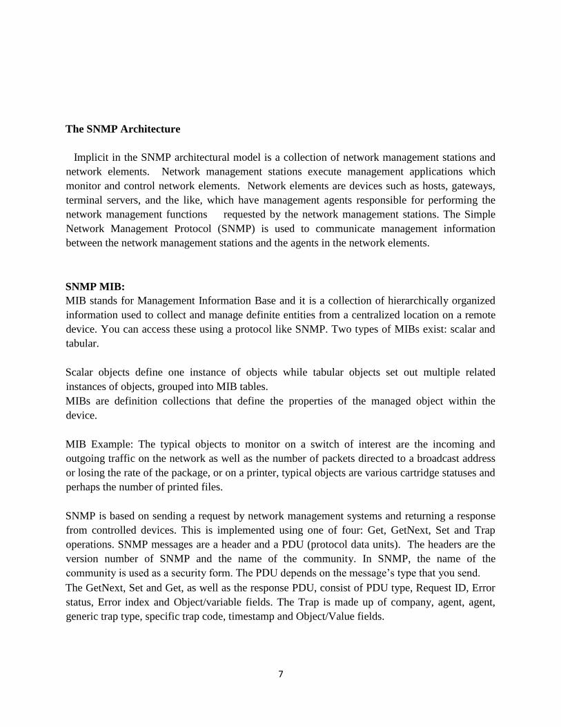
MIBs constitute the set of definitions that define the properties of the managed object in the
device to be managed (such as switch, router, etc.) Each managed device stores a value database
for each of the definitions written in the MIB. In fact, it is not a database as such, but dependent
on implementation. Each SNMP equipment supplier has under their control an exclusive part of
the MIB tree structure.
Figure 2: SNMP process
MIB files are text files where objects are defined sequentially, there is component: -
sysName object,
- Syntax keyword is followed by the data type (Integer, Timestamp, Null, DisplayString,
Counter)
- Max-Access keyword is followed by the access type (Read only, Read Write)
- Status keyword is followed by the status type (current, mandatory, obsolete, deprecated,
optional)
- ::= {system 5} the father object of this object in the MIB tree
SNMP OID
OIDs stands for Object Identifiers. OIDs uniquely identify managed objects in a MIB hierarchy.
This can be depicted as a tree, the levels of which are assigned by different organizations. Top
level MIB object IDs (OIDs) belong to different standard organizations.
The MIB objects are stored in a database, the SNMP chief utilize it to inquiry remote device, it
ought to utilize the item name and retrieve the OID from the tree.

9
OID represents object identifier, OID is the way from the base of the tree down to the object, it
is a unique number consists of each objects number in the path separated by dot (for example
2.5.2.5.2.3.2.0.0.1), the last one is the index, utilized for tabular object.
These SNMP OID numbers are the ones utilized when setting up custom sensors, to get access to
the proper components of the device wanted to be monitored. OIDs are usually given by the
manufacturers of the devices or can be found in special repositories for the OIDs, where sets of
MIB trees and the particular OIDs can be accessed.
MIB - Remote Network Monitoring
Internet-standard MIB - Network Services Monitoring
Internet-standard MIB - Mail Monitoring
Goals of the Architecture
The SNMP explicitly reduces the number and complexity of management functions performed
by the manager himself.
The goal is attractive in many respects:
- The cost of development for the software required to support the protocol is consequently
reduced.
- the degree of management function supported remotely increases, allowing for a full use
of internet resources in the management process.
- The level of remotely supported management function is increased, the sophistication of
management tools has been restricted to the minimum possible extent.
- Developers of network management tools can easily understand and use simplified sets of
management functions.
- Another goal of the Protocol is that the monitoring and control functional paradigm be
sufficiently extensible to accommodate additional aspects of network operation and management
that may be unexpected.
- To ensure that architecture is as independent as possible from the architecture and
mechanisms of certain hosts or gates.
Elements of the Architecture
The architecture of SNMP defines a solution to the problem of network management as
follows:
(1) the management information
(2) representation of the protocol's communicated management information,
(3) Operations Supported on Management Information
(4) the form and meaning of exchanges between management objects,
(5) the definition of Administrative Relationships among management entities
(6) the form and meaning of references to management information.

10
Protocol Specification
The network management protocol is an application protocol that allows inspection or alteration
of variables of the agent's MIB.
The exchange of messages, fully and independently represented within a single datagram UDP
using the basic encoding rules, will be used to make communication between protocol entities,
consisting of a version identifier, a SNMP community name and a protocol data unit (PDU). A
protocol entity receives messages on the host associated to UDP port 161 with all the
messages with the exception of the traps reports.
E.g., all messages except Trap-PDU messages). For further processing, messages which report
traps should be received at UDP port 162. No messages over 484 octets must be allowed for the
implementation of this protocol. But implementations should support larger datagrams whenever
possible.
It is obligatory that the SNMP implementations support the five PDUs: GetRequest,
GetNextRequest, GetResponse, SetRequest, and Trap.
However, there are some challenges. For instance, some protocols, such as SNMP, require the
creation of certain glue-code to make the adaptation possible. Such glue-code includes, for
example, metadata, that is to say information about the object structure described on the
management interface.
Moreover, it is desirable that no trace of the management protocol used for its obtaining is
substantiated in the final application code. Until now this can only be achieved by some kind of
hand-coding, which means that instant management can not be carried out.
11
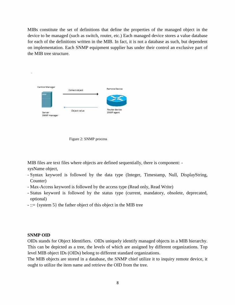
Literature review
DDoS attacks are very harmful to OSI layer protocol; each OSI layer serves the type of protocol
just as the application layer serves HTTP. Network layer protocol serves ICMP.
DDOS Attacks
UDP flood is one of the most common types of DDoS attacks, where attackers use random ports
on the victim machine to flood with UDP packets. Another type of DDoS is an SYN flood
attack, where the three-way handshake TCP connections are used.
Many researchers have done experiments and researches in order to identify and explain the IDS:
In (Purvag P.), identified the Intrusion detection as a process of identifying and responding to the
malicious activity targeted at computing and networking sources. By detecting anomalies in the
mobile ad-hoc network including inconsistencies in the routing tables and activities on other
layers. Two components were proposed in their research the first one is about specifying
intrusion detection type in a manner which is more suitable for an analytical environment; and
the second is a computational model which describes methodology for preparing intrusion
detection data stepwise from network packets to data structures in a way to be suitable for
sophisticated analytical methods such as data mining, statistics, and computational intelligence.
[1]

12
According to (Richa & Mittal, 2014), the IDS defined as a monitoring and prevention device,
where an IDS collects network traffic and then a preprocessing procedure starts collecting
network traffic. Intrusion recognition then starts operating to detect and classify packets.
An IDS system is divided into two types based on detection mechanism:
1- Misuse detection:
Misuse detection implements a prototype of traffic behavior and then compares current traffic
with prototype traffic to identify a DDoS attack. The mechanism working on misuse detection
can achieve a high accuracy rate for detecting a DDoS attack, although the main drawback is that
misuse detection will not detect any new DDoS attack that has not happened previously and been
recorded in the prototype.
2- Anomaly detection:
Works by identifying a probable pattern of network traffic. In this type of IDS system, the
network packet may report a possible attack but not if no prototype pattern has been recorded
before. Anomaly IDS has a low detection rate with a high false alarm rate. [2]
In (Biradar et al.) proposed a security based multicast routing mechanism in MANET. Proposed
method finds multicast routes to receivers by calculating route request packets and route reply
packets. Performance of the proposed method is compared with (ODMRP) on-demand multicast
routing protocol and enhanced on-demand multicast routing protocol. They presumed that the
proposed method delivers better PDF, reduced packet delay and reduced overheads (delivery
ratio of the packet). [3]
Intruders can use sophisticated tools to attack the host on the network and gain access to sensitive
data in organizations like hospitals, the military, universities, etc. are sharing data, which are
highly sensitive and important, especially with advanced network communication growing.
In (Mulert et al. 2012), worked on Reactive intrusion detection node blacklisting scheme.
They conducted a vulnerability analysis of SAODV to recognize uncertain threats to the
algorithm, such as black holes, medium access control layer misconduct, assets consumption, etc.
They contrast this helplessness investigation and proposed method to handle the distinguished
attacks. They proposed method that incorporate multipath routing, incentive schemes, directional
antennae, packet leashes etc. by Analysis of SAODV to identify unresolved threats to the
algorithm. [4]

13
Another IDS solution, which is able to detect the DoS (Denial of Service) attack was suggested
by (Sharma et al.) in 2011. The proposed method can find the intrusion, depending on the misuse
Detection which has less false negative. Proposed System detects the intruders using the IP
address so it is a safer transmission in Denial of Service and Man in Middle Attack (Man-in-the-
middle attack, occurs when the attacker is able to read and edit the communications between the
two parties without the parties are being aware of the presence of the attacker.) [5]
Another method provided by (Ming-Yang Su, 2011), helping in finding and separating the
malicious nodes in the network. An Anti-Black-hole mechanism should be performed by all IDS
nodes, this mechanism assesses the suspicious estimation of a node by calculating difference
between RREPs and RREQs transmitted over the node. At the point when a suspicious value
exceeds the threshold value, an IDS adjacent will broadcast a block message, advising all nodes
on the system, requesting them to helpfully to cooperatively isolate and disconnect the
malicious node. [6]
A new method for securing the network is proposed by (Bhatnagar et al.) in 2010, who is also
discussed about various challenges in intrusion detection system for wireless network and
examined some issues and difficulties of IDS system for wireless sensor network and suggested a
secure method that can recognize possible intrusion in the network, alarming client after
intrusion had been discovered and reconfigure the system. In this paper, authors are mainly
focused in multi hop WSNs. Proposed intrusion detection system defenses the strength of a
wireless sensor networks using decision making technique. [7]
In (Madhavi, 2008), inspect the vulnerabilities of wireless network and contended that intrusion
detection must be incorporated in the security system. They proposed a Mobile Intrusion
Detection System suitable for wireless networks, which distinguishes the misbehavior of the
nodes, irregularities in packet sending, for example, some nodes dropping packets. Proposed
System does depend on overhearing packet transmissions of neighboring nodes. Proposed
System sets the various thresholds dynamically. [8]
Another perspective to describe an intrusion detection system based on decision tree technology
was presented by (Juan Wang et.al). The experiment results show that the C4.5 decision tree is
feasible and effective, and has a high accuracy rate. His experimental study shows that the C4.5
decision tree is an effective technique for the implementation of decision tree and it gives almost
90% of classifier accuracy. But in this approach the error rate remains the same because it is very
useful in detecting intrusions at different times, that’s why unsupervised machine learning
methods of "clustering should be used. The dataset that was used in these researchers' work was
14
a KDD dataset, which includes denial of service, User to Root Attack (U2R), Remote to Local
Attack (R2L) and Probing attack. [9]
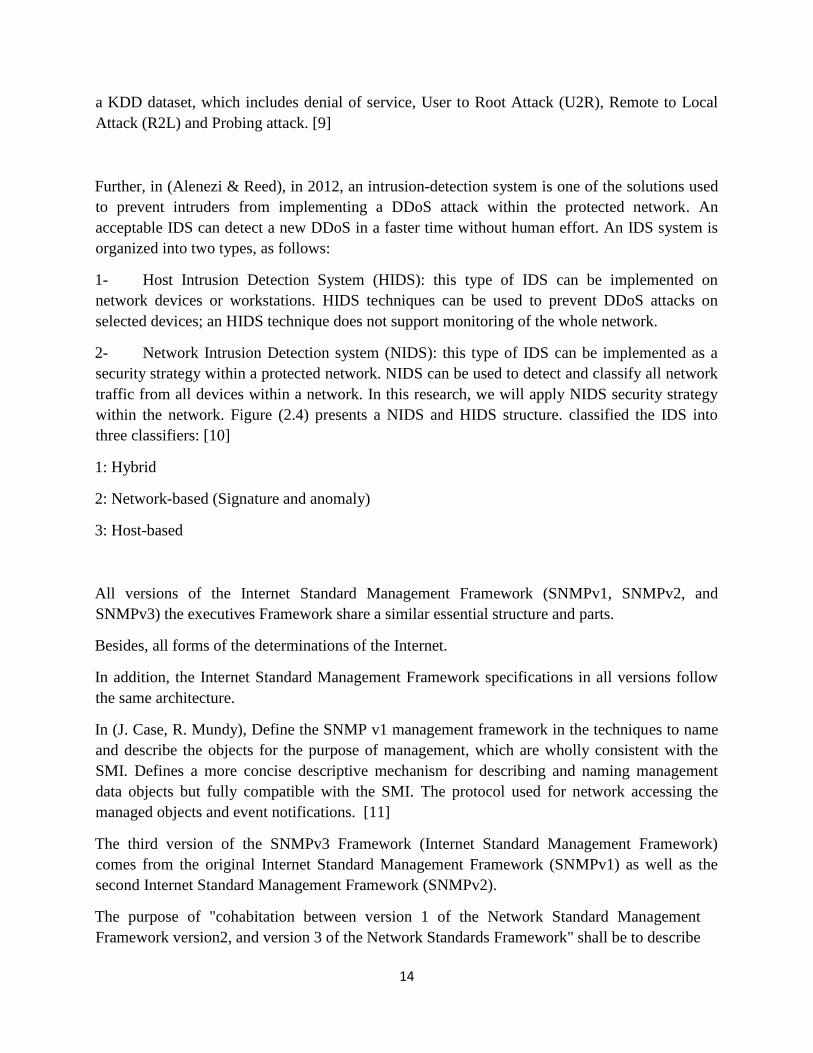
Further, in (Alenezi & Reed), in 2012, an intrusion-detection system is one of the solutions used
to prevent intruders from implementing a DDoS attack within the protected network. An
acceptable IDS can detect a new DDoS in a faster time without human effort. An IDS system is
organized into two types, as follows:
1- Host Intrusion Detection System (HIDS): this type of IDS can be implemented on
network devices or workstations. HIDS techniques can be used to prevent DDoS attacks on
selected devices; an HIDS technique does not support monitoring of the whole network.
2- Network Intrusion Detection system (NIDS): this type of IDS can be implemented as a
security strategy within a protected network. NIDS can be used to detect and classify all network
traffic from all devices within a network. In this research, we will apply NIDS security strategy
within the network. Figure (2.4) presents a NIDS and HIDS structure. classified the IDS into
three classifiers: [10]
1: Hybrid
2: Network-based (Signature and anomaly)
3: Host-based
All versions of the Internet Standard Management Framework (SNMPv1, SNMPv2, and
SNMPv3) the executives Framework share a similar essential structure and parts.
Besides, all forms of the determinations of the Internet.
In addition, the Internet Standard Management Framework specifications in all versions follow
the same architecture.
In (J. Case, R. Mundy), Define the SNMP v1 management framework in the techniques to name
and describe the objects for the purpose of management, which are wholly consistent with the
SMI. Defines a more concise descriptive mechanism for describing and naming management
data objects but fully compatible with the SMI. The protocol used for network accessing the
managed objects and event notifications. [11]
The third version of the SNMPv3 Framework (Internet Standard Management Framework)
comes from the original Internet Standard Management Framework (SNMPv1) as well as the
second Internet Standard Management Framework (SNMPv2).
The purpose of "cohabitation between version 1 of the Network Standard Management
Framework version2, and version 3 of the Network Standards Framework" shall be to describe

15
the coexistence between the management SNMPv3 framework, SNMPv2 and the original
management framework SNMPv1. Four aspects of co-existence were described:
• MIB documents conversion from SMIv1 into SMIv2 format
• Mapping notification parameters
• Coexistence approaches among entities that support the different versions of SNMP
within a multi-lingual network, particularly protocol operations processing in
multilingual implementations and behaviour.
• The Model and Community-Based Security for the Message Processing of SNMPv1 that
provides mechanisms to adapt SNMPv1 and SNMPv2c to the View Access Control
Model (VACM).
The group of interfaces specifies a general set of managed objects that allow independent
management of any of its component. "The MIB module describes generic objects for sub-layers
of the network interface and incorporates the extensions defined in the MIB-II ifTable updates.
MIB defines a value object, ifNumber, which reflects the number of network interfaces present
on the system. Each interface is identified by a unique value of the IfIndex object, and ifIndex's
value is restricted by the following description: It is between 1 and the value of ifNumber". At
least one re-initialisation of the network management system of the entity until the next re-
initialization must remain consistent at each interface. [12]
For an early detection of distributed denial of service (DDoS) attacks a methodology for utilizing
network management systems was proposed by (Joao BD Cabrera, Lundy Lewis) in 2001. They
depended on information from MIB (management information base) traffic variables collected
from the systems participating in the attack. Three types of DDoS attacks were effected on a
research test bed, and MIB variables were recorded. Using these datasets, they could show how
there are MIB-based precursors of DDoS attacks that render it possible to detect them before the
target is shut down. Most important, they described how the relevant MIB variables at the
attacker can be extracted automatically using statistical tests for causality. The statistical tests
applied in the time. [13]
In (2002, João BD Cabrera, Lundy Lewis), described a principled approach for discovering
precursors to security violations in databases recorded from multiple domains in networked
information systems. These precursors are used by security analysts for better understanding of
the evolution of complicated computer attacks, and also to trigger alarms indicating that an attack
is imminent.
The usage of these temporal rules as an integrated information assurance infrastructure as well as
interference such as prevention, detection, response and tolerance are called Proactive Intrusion
Detection. A methodology is planned for discovering Precursor Rules databases containing
16
statistic associated with completely different regimes of a system. These Precursor Rules relate
precursor events. [14]
Cases which have large chunks of repetitive data need to be exported periodically, a push
mechanism called IP Flow Information Export (IPFIX) can be used, using a push protocol such
as IPFIX instead of a polling protocol like SNMP is needed to avoid the identifying new IPFIX
elements for existing MIB objects already fully specified. Avoiding exporting the IPFIX and
SNMP sourced data together to enable the correlation. [15]
(A. Laurent, 2009), Considered the performance of SNMP with complete coverage of its features
and parameters. The first step is about collecting and analysis SNMP traces to identify the most
used patterns in real networks, once the suitable patterns are identified, they can be used to
identify common management practices that can be evaluated and compared to other
management technologies. In the second step, it will be comparing the parameters used in their
research with other studies because some parameters were missing such as (security, bulk data
retrieval, mixing polling and notifications). [16]
(Mahendra, 2016), Said Mostly SNMP based solutions take advantage of the proxy based
deployment model, or some form some kinds of the agent. This deployment model sees a proxy
type device deployed between the management station and SNMP agent (managed device). [17]
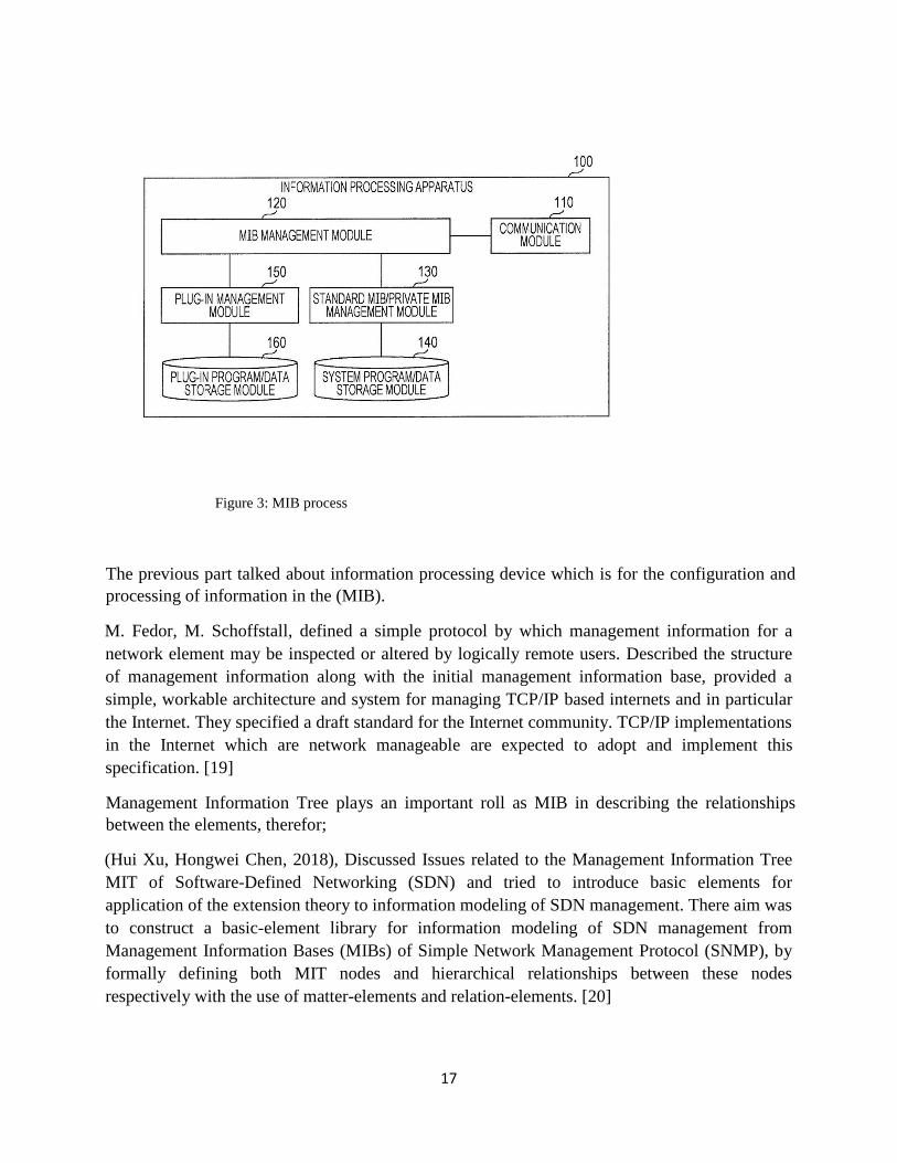
In (2015, Kentaro Yamada), an information processing device is provided for the configuration
and processing of information in a distributed environment in the Management Information Base
(MIB). The information processing apparatus adds a new feature to the information processing
apparatus as a plug-in and receives information regarding the new feature added by a first add-on
in the managing unit, where MIBs other than standard MIBs are managed, as a management
information base (MIB) of the Simple Network Management Protocol (SNMP). An information
processing device is provided for the configuration and processing of information in a distributed
environment in the Management Information Base (MIB). [18]
17
Figure 3: MIB process
The previous part talked about information processing device which is for the configuration and
processing of information in the (MIB).
M. Fedor, M. Schoffstall, defined a simple protocol by which management information for a
network element may be inspected or altered by logically remote users. Described the structure
of management information along with the initial management information base, provided a
simple, workable architecture and system for managing TCP/IP based internets and in particular
the Internet. They specified a draft standard for the Internet community. TCP/IP implementations
in the Internet which are network manageable are expected to adopt and implement this
specification. [19]
Management Information Tree plays an important roll as MIB in describing the relationships
between the elements, therefor;
(Hui Xu, Hongwei Chen, 2018), Discussed Issues related to the Management Information Tree
MIT of Software-Defined Networking (SDN) and tried to introduce basic elements for
application of the extension theory to information modeling of SDN management. There aim was
to construct a basic-element library for information modeling of SDN management from
Management Information Bases (MIBs) of Simple Network Management Protocol (SNMP), by
formally defining both MIT nodes and hierarchical relationships between these nodes
respectively with the use of matter-elements and relation-elements. [20]

18
According to the previous researches, we can say identifying a new data source for a monitoring
network of characteristics data. For typical data from the new data source, the device initiates a
quarantine period. During the quarantine period the characteristic data of the new data source is
monitored from the input to the machine learning analyzer.
During the quarantine period, it models the characteristic data from the new data source to
determine if the characteristic data of the new data source can be used in the machine-based
analyzer reliably. After the quarantine period the device gives the machine learning analyser the
characteristic data from the new data source on the basis that characteristic data from the new
data is reliable. [21]
With the rapid development of the modern information technology and communications industry,
traditional broadcasting is experiencing this reform following digitization, networking, and
mobile portability. Therefore, ensuring the coverage and stability of wireless broadcast signals is
one of the keys to the reform of terrestrial digital broadcasting signals. Therefore, the measured
data provided by the coverage test of wireless broadcast signals has important reference value for
its coverage planning, implementation and post-maintenance. It has an important role in the
horizontal and vertical development of wireless broadcasting therefor; a transmission test system
introduced based on SNMP protocol by Java. It can quickly measure FM signal field strength,
multipath and other information, and combine these values with an external GPS to save the
values to the local text file. The broadcast signal audio is downloaded and saved to the local disk.
The whole DT system operates simply and the power consumption is low. It also has the
characteristics that the DT system has small volume. The drive test is an important way used to
test the broadcast signals quality and plays an important role in wireless networks optimization.
[22]
Since the network structure is becoming more and more complex with the continuous expansion
of the scale of computer network. To have better network performance prediction and modern
network management, it is necessary to have an accurate network topology information
However, the dynamic characteristics of modern networks make it difficult to obtain the network
topology information manually. Topology discovery technology was analyzed, the related
theories at home and abroad, and application, the existing SNMP based network topology
automatic discovery algorithm with high complexity shortcomings, put forward more effective
topology algorithm, improved the efficiency and quality of network management, and the
improvement and development of the network. [23]
(Cui-Mei Bao), said in his experiment that Results of the experiment using MIB datasets
collected from real experiments involving a DDoS attack demonstrate that it can be an effective

19
way for intrusion detection. The network attacks are detected with high efficiency, and classified
with low false alarms. [24]
The involved SNMP MIB variables are selected by an effective feature selection mechanism and
gathered effectively by the MIB update time prediction mechanism.
Using MIB and SVM, it could achieve fast detection with high accuracy, the minimization of the
system burden, and extendibility for system deployment.
The intrusion detection mechanism with hierarchical structure setup has two phases, which first
distinguishes attack traffic from normal traffic and then determines the type of attacks in detail.
In (Raúl Sánchez, Álvaro Herrero, Emilio Corchado spain, 2018), Their aim was being one step
toward that purpose to study the combination of clustering and visualization techniques. [25]
To do that, the mobile visualization connectionist agent-based intrusion detection system
(MOVICAB-IDS), proposed as a hybrid intelligent IDS based on visualization techniques, is
upgraded by adding automatic response thanks to clustering methods.
Then checking the validity of the proposed clustering extension, it has been applied to the
identification of different anomalous situations related to the simple network management
network protocol by using real-life data sets. They studied also different ways to apply neural
projection and clustering techniques.
Through the experimental validation it is shown that the proposed techniques could be
compatible and consequently applied to a continuous network flow for intrusion detection.
Firewall characteristics and Intrusion Detection Systems (IDS) and points out the shortcomings
of the Firewall were studied by (YuYuan huiaLi, Yong meia, Deng Yingb, 2017)
Then analyzed the linkage mechanism of Firewall and IDS based on SNMP Protocol, and puts
forward a kind of linkage model based on IDS and Firewall. Finally, the effectiveness of the
linkage mechanism is verified by the simulation results. [26]
In (Purvag Patel, Chet Langin, Feng Yu, and Shahram Rahimi) proposed that network Intrusion
Detection Math (ID Math) consisting of two components: the first one is a way of specifying
intrusion detection types in a manner which is more suitable for an analytical environment; and
the second one is a computational model which describes methodology for preparing intrusion
detection data stepwise from network packets to data structures in a way which is appropriate for
sophisticated analytical methods such as computational intelligence, statistics and data mining.
[27]
20
In (S. Staniford-Chen, S. Cheung, R. Crawford, M. Dilger), they explained the nature and Grids
system operation. Firstly, they presented a simple example to illustrate the main concept, and
discussed the architecture and components that make up the distributed system. Then gave a
more detailed description of how these components operate to detect intrusions. [28]
Grids data sources are modules that monitor activity on hosts and networks and send reports of
detected activity to the engine. The activity is reported in the form of a node or an edge for
possible inclusion in an activity graph. All Grids software is in the form of modules with a
standardized interface. The modules are started, stopped, it is controlled by a module controller
process located on each host on the network.
Each part has two modules: the software manager and the graph engine. The software manager
is responsible for managing the state of the hierarchy and the distributed modules. The hierarchy
is re-arranged dynamically by drag-and drop in a user interface, and starting and stopping
particular modules is similarly automated.
Intrusion detection is the statement of identifying unauthorized use, misuse, and abuse of
computer systems by both system insiders and external penetrators. The proliferation of
heterogeneous computer networks provides additional implications for the intrusion detection
problem. The increased connection of computer systems gives greater access to outsiders, and
makes it easier for intruders to avoid detection. IDS’s are based on the belief that an intruder’s
behavior will be noticeably different from that of a legitimate user.
In 2017 (Snapp SR, Brentano J), They designed and implemented a prototype Distributed
Intrusion Detection System (DIDS) that combines distributed monitoring and data reduction
(through individual host and LAN monitors) with centralized data analysis (through the DIDS
director) to monitor a heterogeneous computer network. [29]
A main problem considered in their work is the Network User Identification problem, which is
concerned with tracking a user moving across the network, possibly with a new user-id on each
computer. Initial system prototypes have provided quite favorable results on this problem and the
detection of attacks on a network.
The impact of the DDoS attacks on the network layer and application layer is an important issue
in the network effectiveness, according to (M. A. Almseidin), In his research, he studied the
effects of DDoS attacks in both the network layer and application layer, including modern DDoS
attacks such as (SIDDOS and HTTP Flood) attacks. He has also created a system to collect a
dataset from a controlled environment using a network simulator. The dataset was generated
through the following stages: data collecting, data preprocessing and classification. Unlike other
datasets, the proposed dataset includes 2,160,668 records with 28 attributes and with no duplicate
records. The proposed dataset includes four types of attacks, organized as follows: (Smurf, UDP-
Flood, HTTP-Flood, and SIDDOS). [30]
He used some algorithms such as Multilayer Perceptron (MLP), Naïve Bayes and Random Forest
algorithms to evaluate the dataset models. The MLP classifier achieved the highest accuracy rate

21
(98.63%) for detecting and classifying DDoS attacks with the longest time for building the
training model; the Random Forest classifier achieved 98.01% for detecting and classifying
DDoS attacks; the Naïve Bayes achieved 96.91% for detecting and classifying DDoS attacks,
and therefore the Naïve Bayes classifier achieved the fastest time for building the training model.
CHAPTER THREE: DESIGN AND METHODOLOGY
In this section we summarise the design and the considerations of our testing, the attacks which
we performed and the classified algorithms in the used software (WEKA).
3.1 Intrusion detection system
An IDS works by monitoring system activity through examining vulnerabilities in the system, the
integrity of files and conducting an analysis of patterns based on already known attacks. It also
automatically monitors the Internet to search for any of the latest threats which could result in a
future attack.
It cannot prevent the attacks. at contrary, an Intrusion prevent system (IPS) prevents attacks
before they reach the target by detecting them and stopping them.
An attack is an attempt to compromise confidentiality, integrity, or availability.
There are two primary methods of detection, signature-based and anomaly-based. Any type of
IDS (HIDS or NIDS) can detect attacks based on signatures, anomalies, or both.
The HIDS monitors the network traffic trying to reach its network interface card (NIC), and the
NIDS monitors the traffic on the network.
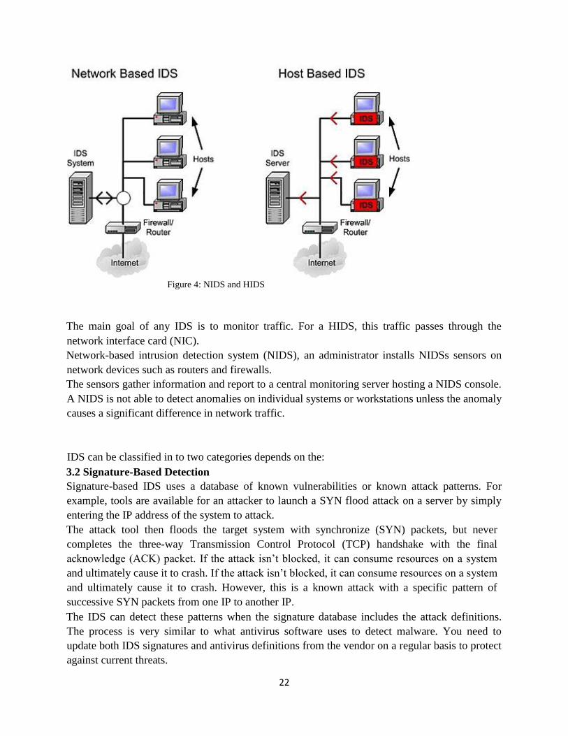
A (HIDS) is an additional software installed on a system on different Internet-facing servers,
such as web servers, mail servers, and database servers, provides protection to each individual
host and can detect potential attacks and protect critical operating system files, as shown in the
figure below:
22
Figure 4: NIDS and HIDS
The main goal of any IDS is to monitor traffic. For a HIDS, this traffic passes through the
network interface card (NIC).
Network-based intrusion detection system (NIDS), an administrator installs NIDSs sensors on
network devices such as routers and firewalls.
The sensors gather information and report to a central monitoring server hosting a NIDS console.
A NIDS is not able to detect anomalies on individual systems or workstations unless the anomaly
causes a significant difference in network traffic.
IDS can be classified in to two categories depends on the:
3.2 Signature-Based Detection
Signature-based IDS uses a database of known vulnerabilities or known attack patterns. For
example, tools are available for an attacker to launch a SYN flood attack on a server by simply
entering the IP address of the system to attack.
The attack tool then floods the target system with synchronize (SYN) packets, but never
completes the three-way Transmission Control Protocol (TCP) handshake with the final
acknowledge (ACK) packet. If the attack isn’t blocked, it can consume resources on a system
and ultimately cause it to crash. If the attack isn’t blocked, it can consume resources on a system
and ultimately cause it to crash. However, this is a known attack with a specific pattern of
successive SYN packets from one IP to another IP.
The IDS can detect these patterns when the signature database includes the attack definitions.
The process is very similar to what antivirus software uses to detect malware. You need to
update both IDS signatures and antivirus definitions from the vendor on a regular basis to protect
against current threats.

23
3.3 Anomaly-Based Detection
Anomaly-based is based on the network behavior detection first identifies normal operation or
normal behavior. By establishing a performance baseline under normal operating conditions. The
IDS provides continuous monitoring by comparing current network behavior against the
baseline. When the IDS detects abnormal activity (outside normal boundaries as identified the
baseline), it gives an alert indicating a potential attack.
Anomaly-based detection is similar to how heuristic-based antivirus software works. Although
the internal methods are different, both examine activity and make decisions that are outside the
scope of a signature or definition database.
IDSs report on events of interest based on their settings. All events aren’t attacks or actual issues,
but instead, they provide a report indicating an event might be an alert or an alarm.
Administrators investigate to determine if it is valid.
The actual reporting mechanism varies from system to system and in different organizations. For
example, one IDS might write the event into a log as an alarm or alert, and then send an email to
an administrator account.
IDS Responses
An IDS will respond after detecting an attack, and the response can be either passive or active. A
passive response primarily consists of logging and notifying personnel, whereas an active
response also changes the environment to block the attack.
3.4 Attacks
In this section we are summarising the DDoS attacks which belongs to the application and the
network layer in the OSI model in our dissertation.
3.4.1 TCP SYN flood
TCP SYN flood is a type of Distributed Denial of Service (DDoS) attack that exploits part of the
normal (TCP three-way handshake) to consume the victim’s resources (targeted server) and
render it unresponsive.
Those TCP connection requests from the sender are faster than the targeted machine which
process them, so causing network saturation.
24
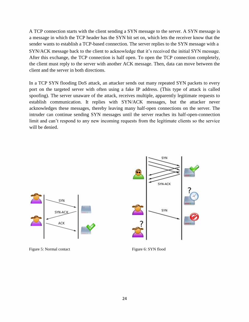
A TCP connection starts with the client sending a SYN message to the server. A SYN message is
a message in which the TCP header has the SYN bit set on, which lets the receiver know that the
sender wants to establish a TCP-based connection. The server replies to the SYN message with a
SYN/ACK message back to the client to acknowledge that it’s received the initial SYN message.
After this exchange, the TCP connection is half open. To open the TCP connection completely,
the client must reply to the server with another ACK message. Then, data can move between the
client and the server in both directions.
In a TCP SYN flooding DoS attack, an attacker sends out many repeated SYN packets to every
port on the targeted server with often using a fake IP address. (This type of attack is called
spoofing). The server unaware of the attack, receives multiple, apparently legitimate requests to
establish communication. It replies with SYN/ACK messages, but the attacker never
acknowledges these messages, thereby leaving many half-open connections on the server. The
intruder can continue sending SYN messages until the server reaches its half-open-connection
limit and can’t respond to any new incoming requests from the legitimate clients so the service
will be denied.
Figure 5: Normal contact Figure 6: SYN flood
25
3.4.2 The Internet Control Message Protocol (ICMP)
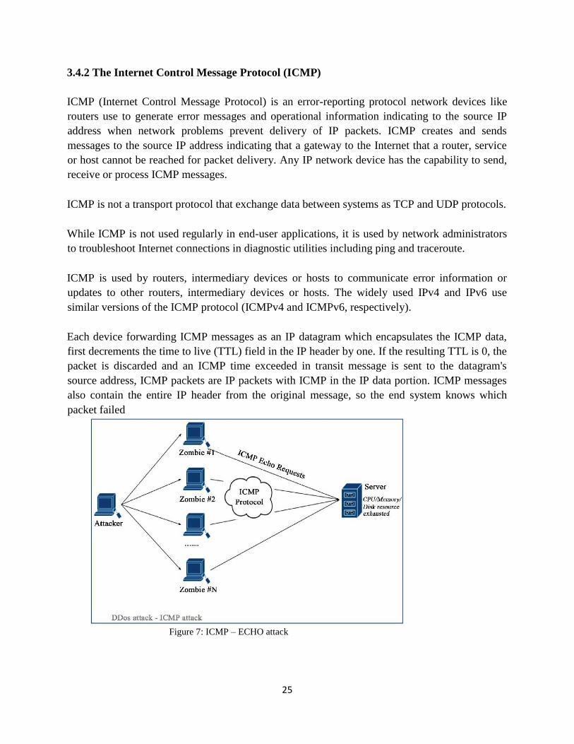
ICMP (Internet Control Message Protocol) is an error-reporting protocol network devices like
routers use to generate error messages and operational information indicating to the source IP
address when network problems prevent delivery of IP packets. ICMP creates and sends
messages to the source IP address indicating that a gateway to the Internet that a router, service
or host cannot be reached for packet delivery. Any IP network device has the capability to send,
receive or process ICMP messages.
ICMP is not a transport protocol that exchange data between systems as TCP and UDP protocols.
While ICMP is not used regularly in end-user applications, it is used by network administrators
to troubleshoot Internet connections in diagnostic utilities including ping and traceroute.
ICMP is used by routers, intermediary devices or hosts to communicate error information or
updates to other routers, intermediary devices or hosts. The widely used IPv4 and IPv6 use
similar versions of the ICMP protocol (ICMPv4 and ICMPv6, respectively).
Each device forwarding ICMP messages as an IP datagram which encapsulates the ICMP data,
first decrements the time to live (TTL) field in the IP header by one. If the resulting TTL is 0, the
packet is discarded and an ICMP time exceeded in transit message is sent to the datagram's
source address, ICMP packets are IP packets with ICMP in the IP data portion. ICMP messages
also contain the entire IP header from the original message, so the end system knows which
packet failed
Figure 7: ICMP – ECHO attack
26
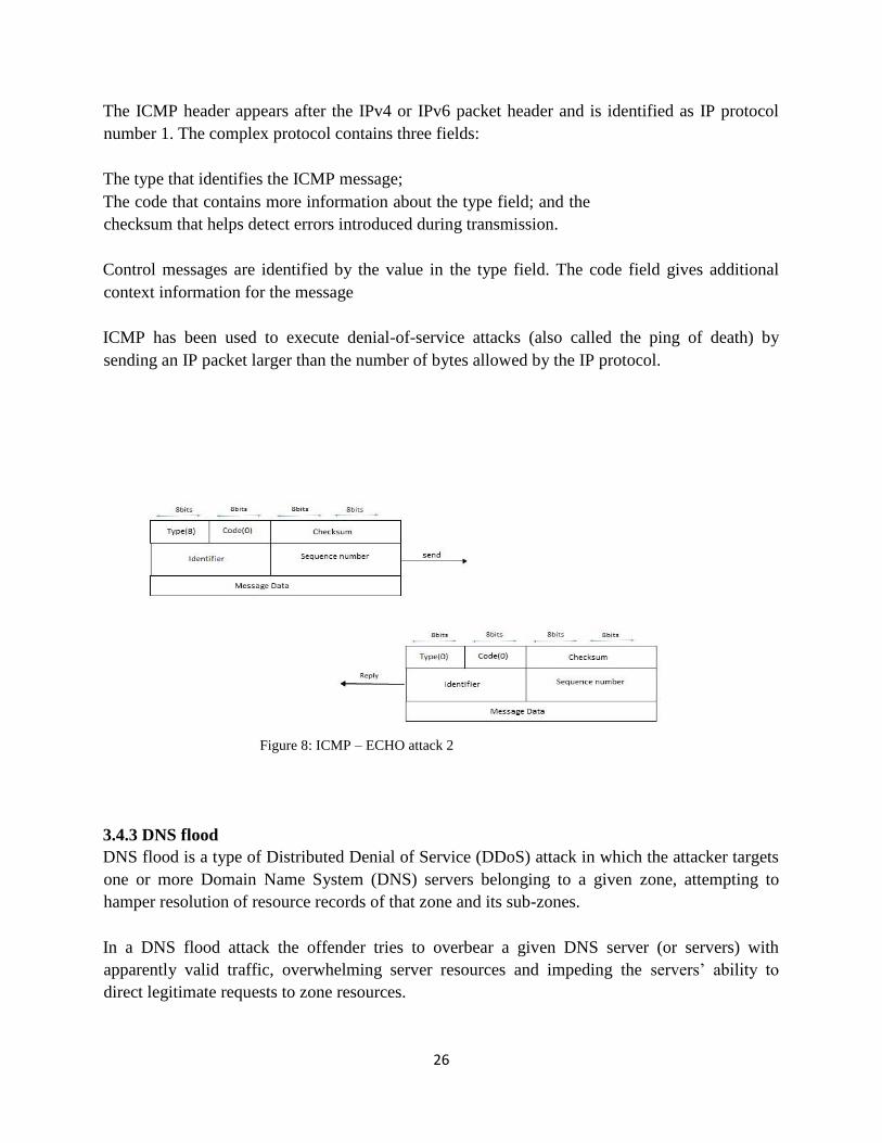
The ICMP header appears after the IPv4 or IPv6 packet header and is identified as IP protocol
number 1. The complex protocol contains three fields:
The type that identifies the ICMP message;
The code that contains more information about the type field; and the
checksum that helps detect errors introduced during transmission.
Control messages are identified by the value in the type field. The code field gives additional
context information for the message
ICMP has been used to execute denial-of-service attacks (also called the ping of death) by
sending an IP packet larger than the number of bytes allowed by the IP protocol.
Figure 8: ICMP – ECHO attack 2
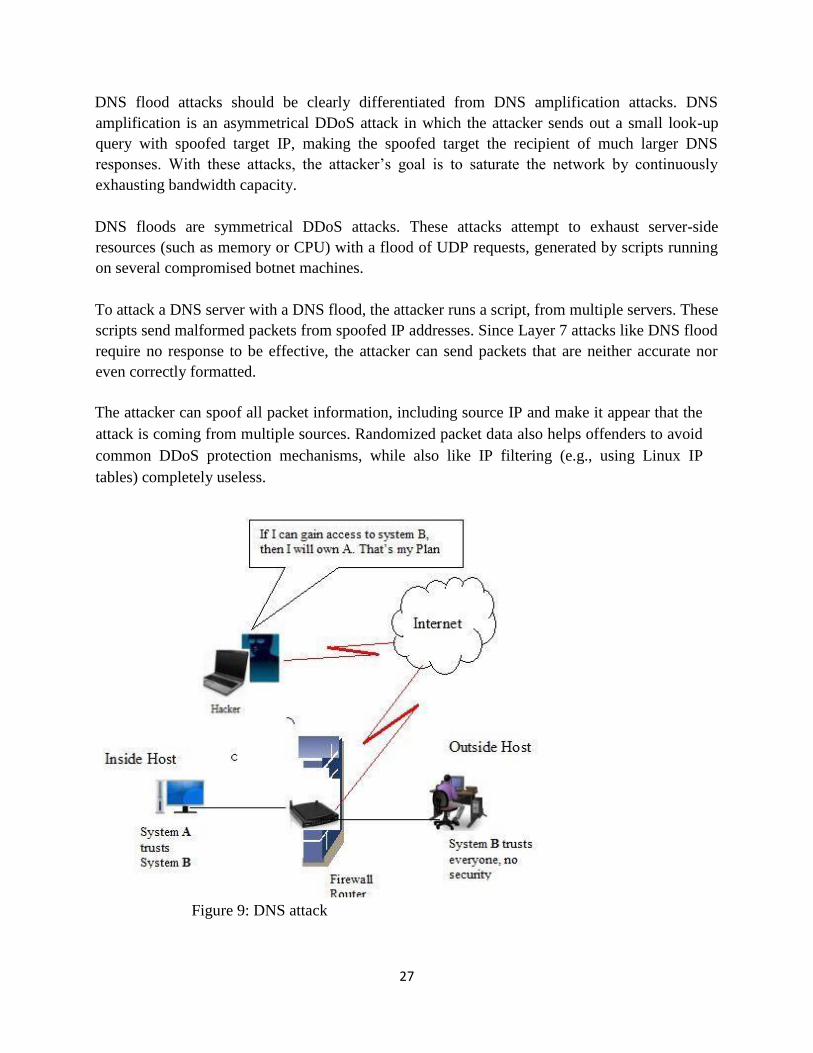
3.4.3 DNS flood
DNS flood is a type of Distributed Denial of Service (DDoS) attack in which the attacker targets
one or more Domain Name System (DNS) servers belonging to a given zone, attempting to
hamper resolution of resource records of that zone and its sub-zones.
In a DNS flood attack the offender tries to overbear a given DNS server (or servers) with
apparently valid traffic, overwhelming server resources and impeding the servers’ ability to
direct legitimate requests to zone resources.
27
DNS flood attacks should be clearly differentiated from DNS amplification attacks. DNS
amplification is an asymmetrical DDoS attack in which the attacker sends out a small look-up
query with spoofed target IP, making the spoofed target the recipient of much larger DNS
responses. With these attacks, the attacker’s goal is to saturate the network by continuously
exhausting bandwidth capacity.
DNS floods are symmetrical DDoS attacks. These attacks attempt to exhaust server-side
resources (such as memory or CPU) with a flood of UDP requests, generated by scripts running
on several compromised botnet machines.
To attack a DNS server with a DNS flood, the attacker runs a script, from multiple servers. These
scripts send malformed packets from spoofed IP addresses. Since Layer 7 attacks like DNS flood
require no response to be effective, the attacker can send packets that are neither accurate nor
even correctly formatted.
The attacker can spoof all packet information, including source IP and make it appear that the
attack is coming from multiple sources. Randomized packet data also helps offenders to avoid
common DDoS protection mechanisms, while also like IP filtering (e.g., using Linux IP
tables) completely useless.
Figure 9: DNS attack

28
Another common type of DNS flood attack is DNS NXDOMAIN flood attack, in which the
attacker floods the DNS server with requests for records that are nonexistent or invalid. The DNS
server expends all its resources looking for these records, its cache fills with bad requests, and it
eventually has no resources to serve legitimate requests.
Although the DNS is quite robust, it was designed for usability, not security, and the types of
DNS attacks nowadays are numerous and quite complex, depending on the communication back
and forth between servers and clients. Trying to prevent or lessen the chance of a DNS attack,
server administrators should consistently monitor traffic and configure servers to duplicate,
separate and isolate the various DNS functions.
Types of DNS attacks include:
-Zero-day attack
-Cache poisoning
-Denial of Service
-Distributed Denial of Service
-DNS amplification
-Fast-flux DNS
3.4.4 Port Scan attack
An attacker launches a port scan by using a listening service to see which ports are open on the
target machine. A port scan attack, therefore, occurs when an attacker sends packets to your
machine, which can vary the destination port. The attacker can use this to find out what services
you are running and to get an enough idea of the operating system you have. Most internet facing
systems get scanned every day, though as long as we harden the firewall on our machines and
minimize the services allowed through it help to not worry about these attacks.
The practice of port scanning is as old as the internet, and while protocols have changed over
time and security tools and systems have evolved as well, port scan alerts still must be attended
to.
Port scans are used by both attackers and defenders for similar reasons. They can be used to map
a network to identify systems, ports and the software in use. This mapping can be done using a
variety of tools at a variety of speeds, depending on whether the person running the scan wants to
minimize the chance of being detected.
Some legitimate endpoint software may even map a local network looking for a printer or other
network resource, and such a scan could look like a port scan attack. Much of the publicly
addressable internet has already been mapped by legitimate services like Shodan, as well as by

29
some more questionable projects, so it is not necessary to do port scans of the internet. But
enterprises should scan their internal networks.
The data gathered by a port scan can be used for attacks or defense. An attacker could use port
scan attack data to flag potentially vulnerable systems with the intention of exploiting those
systems to gain access to the target network.
Types of port scans:
The simplest types of port scans are streams of packets sent to a single host, each succeeding
packet contains of the target host's IP address and an incremented port number. When a packet is
directed to an open port, the target system will reply to the attacker with an appropriate response
packet, signaling to the attacker that the port is open.
The most common type of port scan attack uses TCP SYN packets, which are used to open a new
TCP connection. TCP port scanning is the most common vector for port scan attacks, because the
target systems should respond to incoming packets.
Port scan attacks can be categorized into two types; by whether they target multiple destination
ports at a single IP address known as a vertical scan and target a single port at multiple
destination IP addresses known as a horizontal scan.
3.4.5 Smurf Attack
A Smurf attack is a type of denial of service attack in which a system is flooded with spoofed
ping messages, creates high network traffic on the victim’s network, which often renders it
unresponsive.
The Smurf program sends a spoofed network packet that contains an ICMP ping (to get
information about network state and to determine their operational status of the nodes). The
resulting echo responses to the ping message are directed toward the victim’s IP address. Large
number of pings and the resulting echoes can make the network unusable for real traffic.
Huge numbers of ICMP requests are sent to the victim's IP address, if the source destination IP
address is spoofed and the hosts on the victim's network respond to the ICMP requests, those
create a significant traffic on the victim’s network, resulting in consumption of bandwidth and
ultimately causing the victim’s server to crash.
To avoid Smurf attacks, the hosts and routers can be configured to be non-responsive to external
ping requests or broadcasts. Routers can also be configured to ensure that packets directed to
broadcast addresses are not forwarded.
30
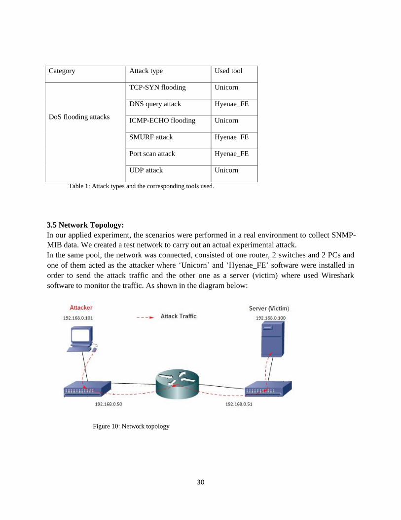
Category Attack type Used tool
DoS flooding attacks
TCP-SYN flooding Unicorn
DNS query attack Hyenae_FE
ICMP-ECHO flooding Unicorn
SMURF attack Hyenae_FE
Port scan attack Hyenae_FE
UDP attack Unicorn
Table 1: Attack types and the corresponding tools used.
3.5 Network Topology:
In our applied experiment, the scenarios were performed in a real environment to collect SNMP-
MIB data. We created a test network to carry out an actual experimental attack.
In the same pool, the network was connected, consisted of one router, 2 switches and 2 PCs and
one of them acted as the attacker where ‘Unicorn’ and ‘Hyenae_FE’ software were installed in
order to send the attack traffic and the other one as a server (victim) where used Wireshark
software to monitor the traffic. As shown in the diagram below:
Figure 10: Network topology
31
The applied Intrusion Detection System
An intrusion-detection system is one of the solutions used to prevent an intruder from
implementing any DDoS attacks within the protected network. An acceptable IDS should be able
to detect a new DDoS in a short time without any human effort. IDS systems experience many
critical issues, such as detecting new attack and minimizing the number of false alarms.
An IDS system is organized into two types as follows:
1- Host Intrusion Detection System (HIDS): this type of IDS can be implemented over
network devices or workstations. HIDS techniques can be used to prevent DDoS attacks over a
selected device; however, they do not support or monitor a whole network. They collect and
analyze data from different sources, such as operating systems and applications. HIDS is
supported by the most recent operating system that allows system auditing and performance
monitoring.
2- Network Intrusion Detection system (NIDS): this type of IDS can be implemented as a
security strategy within a protected network, and can be used to detect and classify all network
traffic from all devices. NIDS has advantages because it can monitor and collect data from a
number of hosts, and is applied in many commercial IDS systems.
It is stated that a huge number of web applications are implemented and exist over the Internet,
which increase the complexity of the attacks, and because of that, using an IDS system has
recently become more common. Some common stages that an IDS system can achieve in the
detection process are as follows:
1- Collect packets based on type of IDS topology (NIDS, HIDS).
2- Preprocess stage and format identifier to extract all necessary attributes.
3- Detect and classify formatted packets.
4- Normal packets pass forward and alarm starts for abnormal packet.
On the other hand, Different types of algorithms may be used by anomaly-based detection, such
as:
1- Genetic algorithm.
2- Artificial neural network.
ANN was the oldest technique used with an IDS system, and the following types of ANN were
implemented with the IDS: ANN supervised learning, ANN unsupervised and hybrid ANN. Each
IDS system includes three main common components:

32
1- Data collection module.
2- Analyzer module.
3- Response modular.
In this section we mention the used algorithms in WEKA software to classify the dataset in
order to detect the attacks which we have been generated in our testing model.
IDS Classifier MLP-ANN
The most common and most well-known Feedforward Neural Network (FFNN) model is called
Multi-Layer Perceptron (MLP). MLP has been successfully applied in a number of applications,
including regression, classification and time series prediction problems, using simple
autoregressive models. The structure of a simple MLP network is clarified in Figure (3.2). MLP
permits the data flow to travel one way, from input to output. There is no feedback; it tends to be
straight-forward networks that companion inputs with outputs. According to (Krse & van der
Smagt, 1997) and (Fausett, 1994), any MLP network can be distinguished by a number of
performance characteristics, which can be summarized in three points:
1: Neural Network Architecture: Overall, MLP architecture can be clarified as the pattern of
connections between the neurons in different layers. The architecture consists of three layers:
input layer, hidden layers, and output layer. Two nodes of each end-to-end layer are connected.
Furthermore, MLP is always fully connected. Each link has a weight, which is limited based on
the training algorithm. Architectures that are more complex have more layers.
2- Training Algorithm: The method of selecting one model from a set of models, which
determines the weights of the connections. The table shown in Figure (10) illustrates examples of
some common transfer functions:
Figure 11 Transfer Functions
(Krse & van der Smagt, 1997)
33
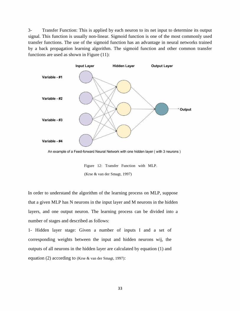
3- Transfer Function: This is applied by each neuron to its net input to determine its output
signal. This function is usually non-linear. Sigmoid function is one of the most commonly used
transfer functions. The use of the sigmoid function has an advantage in neural networks trained
by a back propagation learning algorithm. The sigmoid function and other common transfer
functions are used as shown in Figure (11):
Figure 12: Transfer Function with MLP.
(Krse & van der Smagt, 1997)
In order to understand the algorithm of the learning process on MLP, suppose
that a given MLP has N neurons in the input layer and M neurons in the hidden
layers, and one output neuron. The learning process can be divided into a
number of stages and described as follows:
1- Hidden layer stage: Given a number of inputs I and a set of
corresponding weights between the input and hidden neurons wij, the
outputs of all neurons in the hidden layer are calculated by equation (1) and
equation (2) according to (Krse & van der Smagt, 1997):

34
Hidden Layer
(1)
𝑦𝑗 = (𝑂𝑗) (2)
Where i = 1, 2 . . ., N and j = 1, 2. . . M. z and 𝑦𝑗 are the activation function and output of the 𝑗𝑡ℎ
node in the hidden layer, respectively. z is usually a sigmoid function given in equation (3) as
shown below.
Sigmoid Function
(3)
1- Output stage: The outputs of all neurons in the output layer are given in equation (4). L is
defined as the number of neurons in the output layer, you can note equation 17 in the
following form:
Output Layer Neurons
(4)
𝑓0 is the activation function of the output layer, which is usually a linear function. 𝑌^ is the neural
network output from the single neuron in the output layer. The MLP network is attempting to
minimize error via the classical Back Propagation (BP) Training algorithm. BP learning starts
with all weights initialized randomly, then weights are modified as the algorithm progresses until
steady state values are reached.
2- Error validation stage: ANN continues the learning process until the error minimization
criteria are reached, assuming that the desired output is Y and the produced ANN output
is ˆY. The learning process should stop when the error difference given in Equation (5) is
a minimum. T is the total number of observations used to build the ANN model during
training. Another set of data must be used to validate the developed ANN model
performance. (Haddadi, Khanchi, Shetabi, & Derhami, 2010)
Error Calculation
(5)
In MLP, all the network weights and bias values are assigned random values initially, and the
goal of the training is to find the set of network weights that cause the output of the network to
match the real values as closely as possible. However, we cannot forget that the MLP always
takes the longest time for training (Haddadi, Khanchi, Shetabi, & Derhami, 2010).

35
Random Forest
Random forest classifiers were developed by LEO Breiman and Adele Cutler, combining tree
classifiers to predict new unlabeled data. The predictor depends on the number of (A) that
represent the number of trees in the forest; the attributes are selected randomly, and each number
of trees represents a single forest, and each forest represents a prediction class for new unlabeled
data. In this algorithm, random features selection will be selected for each individual tree (Sujay,
Rupesh, Manoj, Hitesh, & Rina, 2014).
A random forest classifier ensemble learning algorithm for classification and prediction of the
outputs is based on an individual number of trees (Araar & Bouslama, 2014). Using random
forest classifiers, many classification trees will be generated, and each individual tree is
constructed by different parts of the general dataset. After each tree classifies an unlabeled class,
the new object will be implemented and each tree will vote for a decision. The forest chosen as
the winning class is based on the highest number of recorded votes. The number of votes is
calculated as follows:
Random forest algorithms:
1- If there is a dataset, we need to split n samples from the whole dataset, giving (n
samples= number of trees).
2- Each dataset sample needs to be regressed or classified; for each record this is randomly
split among all predictor classes to reach an approximately optimal split. Bagging can be
learned as a special scenario when m (tries) = P (number of predictors).
3- Predict unlabeled classes based on a reassembled number of aggregation prediction
number of trees.
The accuracy rate and error rate for Random Forest Tuning parameters for Random forest (RF)
classifiers can be measured either by splitting the whole dataset, for example by testing 40% and
for training 60%, or by dividing the data into 10s or 20s, etc. After a random forest built model
test, 40% can be used to calculate error rate, and accuracy rate can be measured based on
comparisons of correctly classified instances with incorrectly classified instances (Madbouly,
Gody, & Barak, 2014).
Out of the bag (OOG) is another way of calculating the error rate in this technique; there is no
need to split the dataset because calculation occurs within the training phase. The following
parameters need to be adjusted correctly to reach the highest accuracy rate with a minimum error
rate:
1- Number of trees.
2- The number of descriptors that occur randomly for present candidate’s m (tries).

36
Naïve Bayes
Naïve Bayes is a simple probabilistic classifier that returns p (y|x), and calculates probabilistic
for each class in a dataset and determines discriminative learning to predict the values of the new
class.
A Naïve classifier links the dataset attributes x ∈ X that are used as inputs to the class labels
Z ∈ {1,2,, C}, where X is the attribute space and Z is the class space. Let X = IRD where D
is a real number. The Naïve classifier may be used with discrete and continuous attributes.
This model is called a multi- label problem. The learning function that directly computes
class is called a discriminates model. The main aim is to learn the conditional class
that is used for non-linear and multi-label problems. For this we use equation (6) as shown
below: (Fu, 2012).
Naïve Bayes Non-linear Problem
(6)
The Naïve classifier achieves outputs based on an argument max function that is shown in
equation (7): (Fu, 2012)
Max Function
(7)
Probabilistic classifiers have the following advantages:
1- Option to reject which is used when we are uncertain of the prediction result, so the
prediction result can be ignored since human effort exists.
2- Allow learning function to be changed and a combination of probability functions can be
used to reach highest performance. The main issues are if the direct learning function 𝑝 =
is used and the probability function is changed; there is no need to recalculate .
Balanced classes of some of the collected datasets have unbalanced classes which means
that if we have one million records of normal network traffic where there is only 1
abnormal for 1000 records we can directly train the unbalanced training dataset and easily
achieve an accuracy rate of 99% by just using class always = normal. To handle such
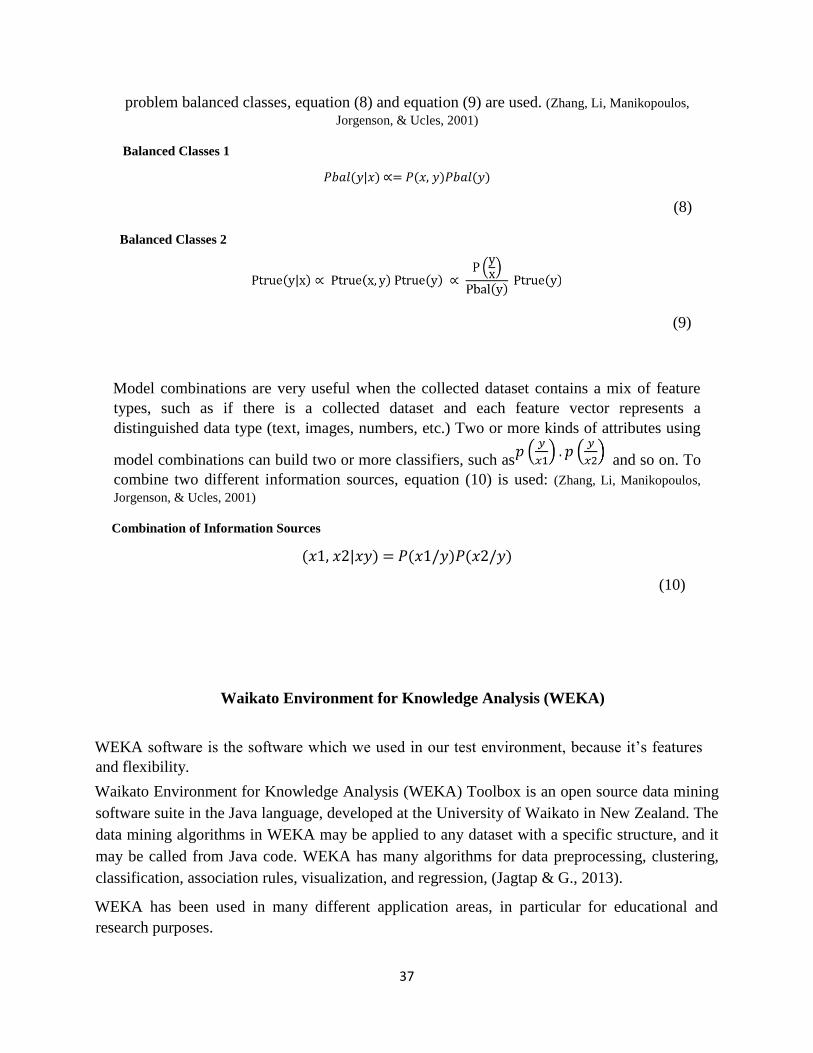
37
problem balanced classes, equation (8) and equation (9) are used. (Zhang, Li, Manikopoulos,
Jorgenson, & Ucles, 2001)
Balanced Classes 1
𝑃𝑏𝑎𝑙(𝑦|𝑥) ∝= 𝑃(𝑥, 𝑦)𝑃𝑏𝑎𝑙(𝑦)
(8)
Balanced Classes 2
(9)
Model combinations are very useful when the collected dataset contains a mix of feature
types, such as if there is a collected dataset and each feature vector represents a
distinguished data type (text, images, numbers, etc.) Two or more kinds of attributes using
model combinations can build two or more classifiers, such as and so on. To
combine two different information sources, equation (10) is used: (Zhang, Li, Manikopoulos,
Jorgenson, & Ucles, 2001)
Combination of Information Sources
(𝑥1, 𝑥2|𝑥𝑦) = 𝑃(𝑥1/𝑦)𝑃(𝑥2/𝑦)
(10)
Waikato Environment for Knowledge Analysis (WEKA)
WEKA software is the software which we used in our test environment, because it’s features
and flexibility.
Waikato Environment for Knowledge Analysis (WEKA) Toolbox is an open source data mining
software suite in the Java language, developed at the University of Waikato in New Zealand. The
data mining algorithms in WEKA may be applied to any dataset with a specific structure, and it
may be called from Java code. WEKA has many algorithms for data preprocessing, clustering,
classification, association rules, visualization, and regression, (Jagtap & G., 2013).
WEKA has been used in many different application areas, in particular for educational and
research purposes.

38
Advantages of WEKA:
1- Free availability under the GNU General Public License.
2- Portability, since it is fully implemented in the Java programming language and thus runs
on almost any modern computing platform.
3- A comprehensive collection of data preprocessing and modeling techniques.
4- Ease of use due to its graphical user interfaces.
WEKA supports several standard data mining tasks; more specifically, data preprocessing to
make the data fully ready and compatible with the next stage of data analysis, clustering,
classification, regression, visualization, and feature selection. WEKA techniques assume that the
data are available as a single flat file or related to different resources, where each data point is
explained by a fixed number of attributes (normally, numeric or nominal attributes, but some
other attribute types are also supported).
The most important feature of WEKA is that it can run on different platforms such as Windows,
UNIX, and Apple Macintosh.
WEKA has many graphical user interfaces that enable easy access to the basic functionality. The
most important graphical user interface is the "Explorer", the screen of which has tabs containing
the following:
1- Preprocess tab data: data can be loaded or transformed using data Preprocess tools, such
as open file, open URL, open database, etc. It supports different file formats, such as
CSV, LibSVM’s format, and its own WEKA ARFF format.
2- WEKA ARFF (Attribute Relation File Format): ARFF file is an ASCII text file that
describes a list of instances sharing a set of attributes.
How does WEKA work!
The WEKA tool can help to convert text, CSV file format to ARRF by using ARFF viewer, and
another feature allows the opportunity to change field names and remove any unnecessary
columns.
After processing, the ARFF file in WEKA lists all attributes, statistics and other parameters that
can be utilized, as shown in Figure (13):

39
Figure 13: WEKA Explorer Panel.
The header of the ARFF file contains:
1- Relation name, which includes the dataset name after token @relation.
2- Attributes list, which includes a definition of attributes, either numeric or nominal.
The second tab, Classify, allows access to classification and regression algorithms: the user can
have the option of applying many different algorithms, such as Bayes, for example Naïve Bayes;
function, for example MLP, lazy, mate, Trees, etc.; and select type of training and test.
Test option gives the user the choice of using four different test mode scenarios on the dataset,
which are represented as follows: use training set, supplied training set, cross validation and split
percentage.
After choosing the classifier and the scenario of the training and testing dataset, the start button
can be used to begin training and testing the classifier. When processing is complete, the result is
shown in the right pane, as shown in Figure (14):

40
Figure 14: WEKA output.
The experiment was conducted using WEKA version 3.7.12 with Intel®, Xeon (R) CPU E5-2680
@ 2.70 GHZ x 4, 12.0 GB RAM and the operating system platform was windows 10. WEKA
version 3.7.12 supports both supervised and unsupervised learning algorithms. We classified the
experiments using supervised learning algorithms, each of which had a number of parameters
and initializing settings which should be known before starting training and testing operations.
The most common classifiers were used in the experiments: MLP, Random forest, and Naïve
Bayes. All models and their results were saved in order to start the comprehensive study.
Comparison of the different classifiers was carried out in order to select the classifier that had the
highest rate of accuracy rate for detecting the DDoS.
The following tables represent the classifier parameters that were used in all the experiments. To
implement multilayer perceptron algorithm, the following parameters should have the initial
values that are shown in Table (3.1):

41
Table 3.1 MLP Parameters
Description.
I Total number of attributes O Total number of classes
T Number of attributes + number of classes
L Learning rate using weight adjustments
M Appling weights update during back propagation
N Number of epochs
H Number of neurons in hidden layer
Seed Random number for setting the initial network weights
Decay Allow learning rate to decrease with time during Training
Activation Function Sigmoid
Sigmoid function is the most common function because it can be used for complex and non-
linear problems. The WEKA tool uses the sigmoid function as an activation function during
MLP operation, activation function:
Table (3.2) shows the parameter setting that is used in the MLP algorithm.
Table 3.2 MLP Parameters
Values. Parameters Value
I 28
O 5
T 33
L 0.3
M 0.2
H a (16)
N 500
Parameters Description
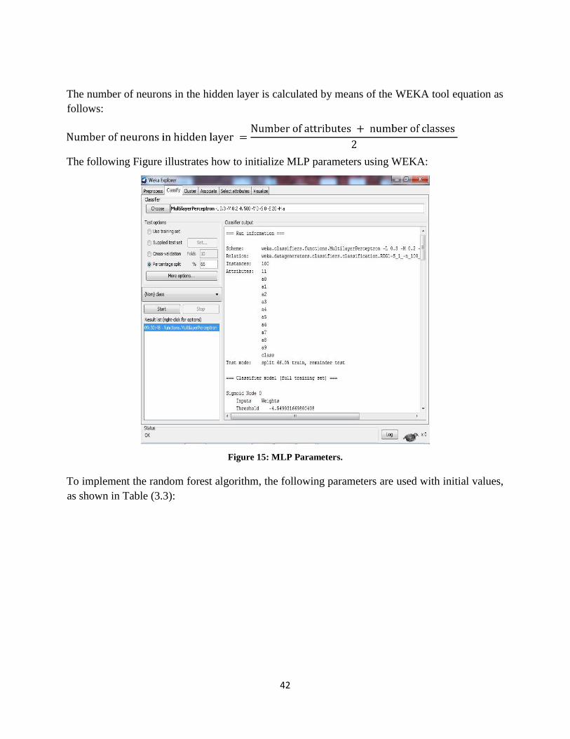
42
The number of neurons in the hidden layer is calculated by means of the WEKA tool equation as
follows:
The following Figure illustrates how to initialize MLP parameters using WEKA:
Figure 15: MLP Parameters.
To implement the random forest algorithm, the following parameters are used with initial values,
as shown in Table (3.3):

43
Table 3.3 Random Forest Parameter Description.
Parameters Description
I Total number of trees
K Random features selection
S Seed for random number generator
Depth Maximum depth of the trees
Number of slots Number of execution slots
Table (3.4) shows the random forest parameters value that were used in our experiments:
Table 3.4 Random Forest Parameter Values.
Parameters Description
I 50
K 0
S 1
Depth 0 (which means unlimited depth)
Number of slots 1
Print Yes
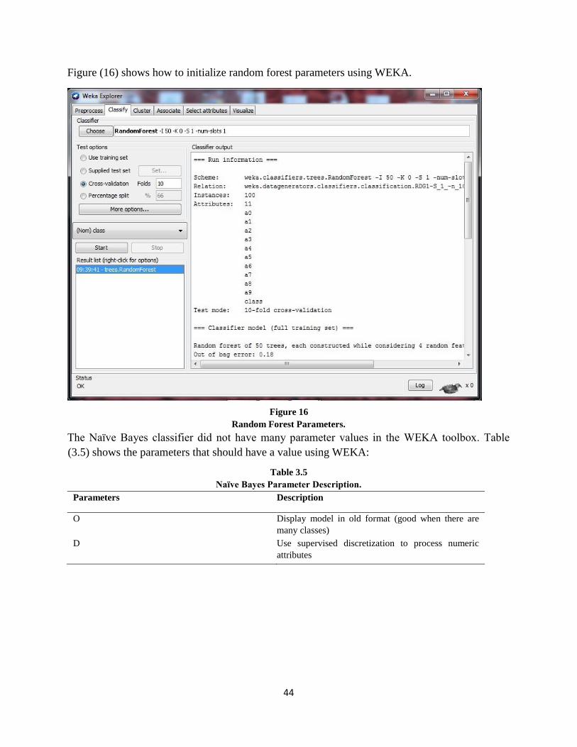
44
Figure (16) shows how to initialize random forest parameters using WEKA.
Figure 16 Random Forest Parameters.
The Naïve Bayes classifier did not have many parameter values in the WEKA toolbox. Table
(3.5) shows the parameters that should have a value using WEKA:
Table 3.5 Naïve Bayes Parameter Description.
Parameters Description
O Display model in old format (good when there are
many classes)
D Use supervised discretization to process numeric
attributes
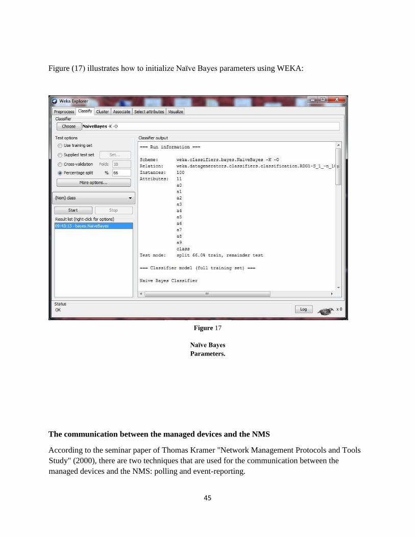
45
Figure (17) illustrates how to initialize Naïve Bayes parameters using WEKA:
Figure 17
Naïve Bayes
Parameters.
The communication between the managed devices and the NMS
According to the seminar paper of Thomas Kramer "Network Management Protocols and Tools
Study" (2000), there are two techniques that are used for the communication between the
managed devices and the NMS: polling and event-reporting.

46
- Polling is a request-response interaction between a manager and an agent.
The manager requests information from the agent, and the agent responds to the manager with
the requested information.
- Event reporting is an action that an agent initiates. It sends information to the manager, who
waits then for the incoming data.
Most of the work within the SNMP management is done by the management applications that are
running on the NMS. Since NMS has the resources to cope with this type of management,
whereas the resources of a node are often limited in terms of CPU performance or limited
memory and should be saved for their real tasks. In other words, the performance impact on the
managed devices and agents should be minimized.
Network management
Network management service consisting of a wide variety of tools, applications, and products to
assist network system administrators in provisioning, operating, monitoring and maintaining new
and existing network deployments.
A network administrator faces many challenges when deploying and configuring network
devices and when operating, monitoring, and reporting on the health of the network
infrastructure and components such as routers, servers, switches and so forth.
Network management helps system administrators monitor each network device and network
activity so that they can isolate and investigate problems in a timely manner for better
performance and productivity.
SNMP and beyond: the demand for high performance, reliable networks is needed because of the
growing dependence on networks for everyday tasks. Part of achieving the goal of best
performance is the active monitoring of networks in order to have effective identification and
prevention of network errors.
Many tools have emerged to aid in performance monitoring of networks.
The most common class of tools is based on the Simple Network Management Protocol (SNMP),
a protocol for sending and transmitting network performance information on IP networks.
Other types of network performance monitoring tools include packet sniffers, flow monitors and
application monitors.
Examples of the various monitoring tools are SolarWind's Orion SNMP monitoring platform,
ethereal packet capture tool, Webmetrics' GlobalWatch and Cisco's NetFlow flow monitoring
tools.

47
Simple Network Management Protocol developed in the late 1980s, has become a standard for
network management. SNMP is a client/server model with a Network Management Station
(NMS) that functions as a client querying an agent that contains a Management Information Base
(MIB) database.
The most common implementation utilizes a management console to perform NMS functions
and agents running on routers, hubs, bridges, and network servers. These agents respond to
queries and collect information.
CHAPTER FOUR
MIB Dataset Collection
The main contribution in this dissertation is to get a new dataset because of the shortage in the
datasets sources. In this setup, we summarise our test to MIB dataset using different tools to
generate normal traffic as well as attack traffic over the test-bed network. Since the test-bed
network was isolated from the Internet, traffic needed to be generated between these two subnets
in order to simulate a real network so that the environment could be as realistic as possible. For
this reason, the LanTrafficV21 was used to generate normal traffic over the network during the
period of the experiment.
In our setup, the LanTraffic software was installed on all the PCs in the subnet. The source and
destination IP addresses were configured so that each PC could send TCP, UDP or ICMP packets
to another PC and vice versa. Different scenarios with different parameters were written and
carried out between the two subnets. On the other hand, the attack traffic generation, out of the
five PCs in the first subnet, 1 PC (attacker) was used to generate attack traffic, and at the same
time, the rest of the PCs were used to send and receive normal traffic. The attack traffic was sent
against the server (victim machine).
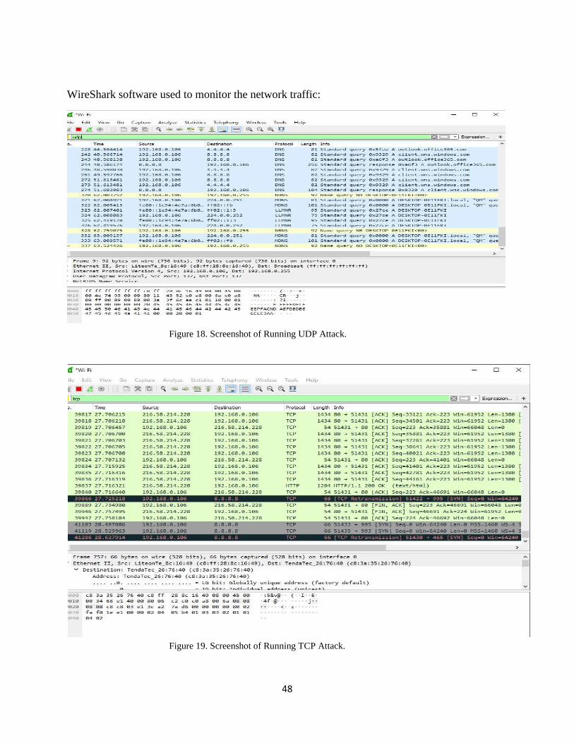
48
WireShark software used to monitor the network traffic:
Figure 18. Screenshot of Running UDP Attack.
Figure 19. Screenshot of Running TCP Attack.
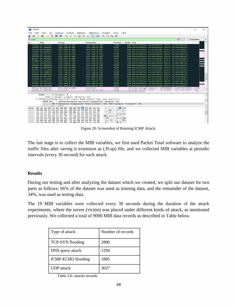
49
Figure 20: Screenshot of Running ICMP Attack.
The last stage is to collect the MIB variables, we first used Packet Total software to analyze the
traffic files after saving it extension as (.Pcap) file, and we collected MIB variables at periodic
intervals (every 30 second) for each attack.
Results
During our testing and after analyzing the dataset which we created, we split our dataset for two
parts as follows: 66% of the dataset was used as training data, and the remainder of the dataset,
34%, was used as testing data.
The 19 MIB variables were collected every 30 seconds during the duration of the attack
experiments, where the server (victim) was placed under different kinds of attack, as mentioned
previously. We collected a total of 9006 MIB data records as described in Table below.
Type of attack Number of records
TCP-SYN flooding 2800
DNS query attack 1294
ICMP-ECHO flooding 1885
UDP attack 3027
Table 3.6: attacks records

50
Average Accuracy (AA) is the main indicator that can be used to study and analyze the
comparison between different classifier algorithms. Average accuracy rate can be calculated
using Equation (11):
Average accuracy
AA =No. of Correctly Classified records
Sum of total records=
𝑇𝑃 + 𝑇𝑁
𝑇𝑃 + 𝐹𝑁 + 𝐹𝑃 + 𝑇𝑁
(11)
The higher number of AA means that the selected classifier is a good prediction model and the
lower number of AA means that the selected classifier is a poor prediction model. Figure (4.4)
represents the (AA) rate for selected classifiers in the experiments.
Figure 21
Average Accuracy Rate.
The MLP classifier achieved the highest (AA) rate of 0.9798%; and the lowest (AA) for Naïve
Bayes classifiers was 0.9507%. We can see that there is no great difference between MLP with
(AA) rate equal to 98.63% and random forest with (AA) rate equal to 0.9763%.
The highest average accuracy rate accomplished by MLP 0.9798%; classifier then Random
Forest
0 0 0
0.9798 0.9763 0.9507
1 2 3
Average Accuracy
MLP Random Forest Naïve Bayes"

51
The network that correctly classifies network intrusion as intrusion is called true positive (TP),
while classifying intrusion as a normal packet (incorrect classification) is called a false negative
(FN). The TP rate can be calculated by means of Equation (15).
True negative (TN) is an indicator of classification of a normal packet as a normal packet
(correctly classified).
CHAPTER FIVE
Conclusion
In this thesis, we have generated a new dataset, initiated because of the lack of open source
datasets and many redundant and duplicate data. The new dataset has new types of DDoS attack
that are not included in previous datasets. Moreover, our dataset focuses on the application layer
and the network layer attack.
Study and analysis of IDS systems and different types of DDoS showed that the IDS system
always has difficult problems in detecting and classifying application layer attacks. Attackers
focus on implementing a DDoS attack on the application layer because they do not need
expensive resources, and they always act as a legitimate user.
We have succeeded in including most modern DDoS attacks, the proposed dataset was imported
to the WEKA toolbox to prepare and test data models for different classifiers.
Our data generation approach allows for the ability to prove the power and effectiveness of
SNMP-MIB data in network anomaly detection by demonstrating the detection of the largest
possible number of the most common and modern attacks that can occur on different network
layers (Network layer, Transport layer and Application layer).
It should be known that, we generated unbiased real-life dataset for intrusion detection purpose.
The data exhibited no unintended property in both normal and the anomalous traffic for all
possible network scenarios.
In the following part we summarize the most effective MIB variables which we used in order to
capture all the anomalies on the network:
In our experiments we used group of SNMP-MIB variables, because there is no single variable
which is capable to capture all anomalies on networks. Therefor; we focused on selecting the
most effective variables for more accurate anomalies detection.
The MIB variable types are defined using the following fields:
1. Variable Descriptor: A textual name for the variable.
2. Object Identifier: The name for the variable in Abstract Syntax Notation (ASN.1) format.

52
We selected 34 MIB variables from 5 MIB groups in MIB-II: Interface (variables of this group
were collected from a particular interface of the router), IP, TCP, UDP, and ICMP. The data
types of the 34 MIB variables were counter 32, which are a non-negative 4-byte integer that is
continuously incremented from 0 to 232; when it reaches its maximum value, it wraps back to 0.
We selected these variables among other MIB variables in the groups because they are affected
more by the attack traffic where these variables are continuously updated with the incoming and
outgoing traffic over the network; thus, they could be more effective for attack detection.
The MIB-II groups with their corresponding variables that are investigated and used are as
follows:
Interface group: This group is not related to a specific layer, it defines information about all the
interfaces of the node including interface number, physical address, and IP address. We selected
8 MIB variables from this group:
1. ifInOctets: These variables represent the total number of octets received on the interface,
including framing characters.
2. ifOutOctets: The total number of octets transmitted out of the interface, including framing
characters.
3. ifoutDiscards: The number of outbound packets which were chosen to be discarded even
though no errors had been detected to prevent their being transmitted.
4. ifInUcastPkts: The number of packets, delivered by this sub-layer to a higher (sub-)layer,
which were not addressed to a multicast or broadcast address at this sub-layer.
5. ifInNUcastPkts: The number of packets, delivered by this sub-layer to a higher (sub-
)layer, which were addressed to a multicast or broadcast address at this sub-layer.
6. ifInDiscards: The number of inbound packets which were chosen to be discarded even
though no errors had been detected to prevent their being deliverable to a higher-layer protocol.
7. ifOutUcastPkts: The total number of packets that higher-level protocols requested be
transmitted, and which were not addressed to a multicast or broadcast address at this sub-layer.
8. ifOutNUcastPkts: The total number of packets that higher-level protocols requested be
transmitted, and which were addressed to a multicast or broadcast address at this sub-layer,
including those that were discarded or not sent.
IP group: This group provides network layer information related to IP, such as the routing table
and the IP address. We selected 8 MIB variables from this group:
1. ipInReceives: The total number of input datagrams received from interfaces, including
those received in error.

53
2. ipInDelivers: The total number of input datagrams successfully delivered to IPv4
userprotocols (including ICMP).
3. ipOutRequests: The total number of IPv4 datagrams which local IPv4 user protocols
(including ICMP) supplied to IPv4 in requests for transmission.
4. ipOutDiscards: The number of output IPv4 datagrams for which no problem was
encountered to prevent their transmission to their destination, but which were discarded.
5. ipInDiscards: The number of input IPv4 datagrams for which no problems were
encountered to prevent their continued processing, but which were discarded.
6. ipForwDatagrams: The number of input datagrams for which this entity was not their
final IPv4 destination, as a result of which an attempt was made to find a route to forward them
to that final destination.
7. ipOutNoRoutes: The number of IPv4 datagrams discarded because no route could be
found to transmit them to their destination. Note that this includes any datagrams, which a host
cannot route because all of its default routers are down.
8. ipInAddrErrors: The number of input datagrams discarded because the IPv4 address in
their IPv4 header's destination field was not a valid address to be received at this entity. This
counter includes datagrams discarded because the destination address was not a local address.
ICMP group: This group defines information related to ICMP, such as the number of packets
sent and received and total errors created. We selected 6 MIB variables from this group:
1. icmpInMsgs: The total number of ICMP messages which the entity received.
2. icmpInDestUnreachs: The number of ICMP Destination Unreachable messages received.
3. icmpOutMsgs: The total number of ICMP messages which this entity attempted to send.
4. icmpOutDestUnreachs: The number of ICMP Destination Unreachable messages sent.
5. icmpInEchos: The number of ICMP Echo (request) messages received.
6. icmpOutEchoReps: The number of ICMP Echo Reply messages sent.
TCP group: This group provides transport layer information related to TCP, such as the
connection table, time-out value, number of ports, and number of packets sent and received. We
selected 8 MIB variables from this group:
1. tcpOutRsts: The number of TCP segments sent containing the RST flag

54
tcpInSegs: The total number of segments received, including those received in error. This count
includes segments received on currently established connections.
3. tcpOutSegs: The total number of segments sent, including those on current connections but
excluding those containing only retransmitted octets.
4. tcpPassiveOpens: The number of times TCP connections have made a direct transition to the
SYN state.
5. tcpRetransSegs: The total number of segments retransmitted; that is, the number of TCP
segments transmitted containing one or more previously transmitted octets.
6. tcpCurrEstab: The number of TCP connections for which the current state is either
ESTABLISHED or CLOSE-WAIT.
7. tcpEstabResets: The number of times that TCP connections have made a direct transition to
the CLOSED state from either the ESTABLISHED state or the CLOSE-WAIT state.
8. tcpActiveOpens: The number of times that TCP connections have made direct transition to the
SYN-SENT state from the CLOSED state.
UDP group: This group provides transport layer information related to UDP, such as the number
of ports and number of packets sent and received. We selected 4 MIB variables from this group:
1. udpInDatagrams: The total number of UDP datagrams delivered to UDP users.
2. udpOutDatagrams: The total number of UDP datagrams sent from this entity.
3. udpInErrors: The number of received UDP datagrams that could not be delivered for reasons
other than the lack of an application at the destination port.
4. udpNoPorts: The total number of received UDP datagrams for which there was no application
at the destination port.
Analysing the results, MLP achieved the highest recall with a rate of 0.9798%, the random forest
classifier achieved an acceptable recall rate of 0.9763%, while the Naïve Bayes represents the
lowest recall rate at 0.9507s%.
False positive (FP) is another performance indicator, where the selected classifier classifies a
normal packet as the intrusion packet (wrong classification).
Figure (22) illustrates the (FPR) that was recorded in the simulation.

55
Figure 22: False Positive Rate
Analysing the (FPR) result, the Random Forest classifier represents the highest value for
classifying a normal packet as an intrusion packet. We can see from Figure (22) that there is no
great difference between the MLP classifier and the Naïve Bayes classifier for classifying a
normal packet as intrusion.
We can summarize the analysis as follow:
1) The MLP classifier represents the highest precision rate in detecting Smurf and HTTP
Flood attacks.
2) The Naïve Bayes classifier is the best classifier for detecting a UDP-Flood attack.
3) There is no great difference between the MLP and Random Forest classifiers in detecting
a SIDDOS attack.
4) Random forest and naïve Bayes are both weak in detecting a Smurf attack.
5) All classifiers represent acceptable precision rates for detecting normal packets.
The Naïve Bayes classifier is the fastest building a training model in all experiments, MLP took
the longest time to build a training model.
By studying and analysing the simulation area we also found that the MLP classifier takes the
longest period of time to build a data model, while the Naïve Bayes has the fastest time. Despite
MLP taking the longest period of time to build a data model, we conclude that using MLP
algorithms is very useful in detecting and classifying modern DDoS attacks because it has the
highest accuracy rates.
0 0 0
0.115 0.114 0.112
FPR
Random Forest MLP Naïve Bayes

56
References:
[1] Purvag Patel, Chet Langin, Feng Yu, and Shahram Rahimi, designing a Network Based
Intrusion Detection System using MIB with the aid of SNMP Agents.
[2] (Richa & Mittal, 2014), "Data Mining Approach IDS K-Mean using Weka Environment",
[3] R. Biradar, S. Manvi, M. Reddy, “Link stability based multicast routing scheme in MANET”,
Computer Networks 54 of Elsevier (2010).
[4] J.V. Mulert, I. Welch, W.K.G Seah, “Security threats and solutions in MANETs: A case
study using AODV and SAODV”, A Journal of Network and Computer Applications 35
(2012) of Elsevier.
[5] M. Sharma, Anuradha, “Network Intrusion Detection System for Denial of Service Attack
based on Misuse Detection”, International Journal of Computational Engineering &
Management Vol. 12, (2011) ISSN (Online).
[6] Ming-Yang Su, “Prevention of selective black hole attacks on mobile ad hoc networks
through intrusion detection systems”, Computer Communications 34 (2011).
[7], R. Bhatnagar, A.K. Srivastava, A. Sharma, “An Implementation Approach for Intrusion
Detection System in Wireless Sensor Network”, International Journal on Computer Science and
Engineering Vol. 02, No. 07, (2010).
[8], S. Madhavi, Tai Hoon Kim,“An Intrusion detection system in mobile adhoc networks”,
(2008)
[9] Juan Wang, Qiren Yang, Dasen Ren, “An intrusion detection algorithm based on decision
tree technology”, In the Proc. of IEEE Asia-Pacific Conference on Information Processing,
2009
[10] Introduction to Version 3 of the Internet-standard Network Management Framework, J.
Case, R. Mundy
[11] Introduction to Version 3 of the Internet-standard Network Management Framework, J.
Case, R. Mundy
[12] The Interfaces Group MIB. 2000, K. McCloghrie
[13] Proactive Intrusion Detection, João BD Cabrera, Lundy Lewis, Xinzhou Qin, Wenke Lee,
Raman K Mehra, 2002
[14] Exporting MIB Variables Using the IP Flow Information Export (IPFIX) Protocol 2017, B.
Claise, P. Aitken, Ed.
[15] SNMP Traffic Analysis Approaches, Tools, and First Results, J. Schönwälder, A.Pras, M.

57
sHarvan, J. Schippers, R. Meent.
[16] Survey of SNMP performance analysis studies Laurent Andrey, Olivier Festor, Abdelkader
Lahmadi, Aiko Pras2 and Jürgen Schönwälder.
[17], Implementation of SNMP on sensor network, Neha, Mahendra Singh Meena, Rajbir
[18], 2015, (Kentaro Yamada,) Configuring and processing management information base (MIB)
in a distributed environment
[19], A Simple Network Management Protocol, 1988, J. Case, M. Schoffstall, M. Fedor
[20], Constructing a Basic-element Library from SNMP MIBs for Management Information Tree
of Software-Defined Networking, Hui Xu, Hongwei Chen, 2018
[21], Automatic detection of information field reliability for a new data source, 2018, Andrea Di
Pietro Grégory, MermoudSukrit DasguptaJean, Philippe Vasseur.
[22], Broadcast signal coverage drive test system based on SNMP protocol
Ruien Zhao, Xin Wan, Yingchun Xia, Quan Liu, 2018
[23], Research on Improved Physical Topology Discovery Based on SNMP
Jing Jiang, XiaoLi Xu, Ning Cao, 2017
[24], Intrusion Detection Based on One-class SVM and SNMP MIB Data, Cui-Mei Bao, 2009
[25], Visualization and clustring for SNMP intrusion detection, Raúl
Sánchez, Álvaro Herrero, Emilio Corchado spain, 2008
[26], Study on Linkage Mechanism of IDS and Firewall Based on SNMP Protocol, YuYuan
huiaLi, Yong meia, Deng Yingb, 2017
[27], Designing a Network Based Intrusion Detection System using MIB with the aid of SNMP
Agents, Purvag Patel, Chet Langin, Feng Yu, and Shahram Rahimi.
[28], A graph based Intrusion detection system for large networks,
Grids {Graph-Based Intrusion Detection System}, S. Staniford-Chen, S. Cheung, R. Crawford,
M. Dilger, J. Frank, J. Hoagland, K. Levitt, C. Wee, R. Yip, D. Zerkle
[29], DIDS (Distributed Intrusion Detection System) - Motivation,
Architecture, and an early prototype, Snapp SR, Brentano J, Dias G, Goan TL, Heberlein LT, Ho
CL, Levitt KN, 2017
[30], Detection and Classification of DDoS Attack using Artificial Neural Network, Mohammad
Almseidin, 2015
Related Documents