SN4500 Primary Navigation Display with Reversionary Attitude Mode And LNAV Roll Steering Installation Manual Sandel Avionics, Inc. 2401 Dogwood Way Vista, CA 92081 Phone (760) 727- 4900 FAX 760) 727- 4899 Website: www.sandel.com Email: [email protected]

Welcome message from author
This document is posted to help you gain knowledge. Please leave a comment to let me know what you think about it! Share it to your friends and learn new things together.
Transcript

SN4500 Primary Navigation Display
with
Reversionary Attitude Mode And
LNAV Roll Steering
Installation Manual
Sandel Avionics, Inc. 2401 Dogwood Way
Vista, CA 92081 Phone (760) 727- 4900 FAX 760) 727- 4899
Website: www.sandel.com
Email: [email protected]

82009-IM, REV K Sandel SN4500 Installation Manual Page ii
[This page intentionally left blank]

82009-IM, REV K Sandel SN4500 Installation Manual Page iii
Table of Contents
1 General Information ....................................................................................................... 1-1
1.1 Introduction .................................................................................................................................................. 1-1
1.1.1 EXPORT CONTROL NOTICE ............................................................................................................. 1-1
1.2 Equipment Description ............................................................................................................................... 1-1
1.2.1 Features ................................................................................................................................................. 1-1
1.3 Installation Planning ................................................................................................................................... 1-2
1.3.1 Installation Planning Cycle .................................................................................................................... 1-2 1.3.2 Post Installation Summary ..................................................................................................................... 1-3
1.4 Interface Planning ........................................................................................................................................ 1-3
1.4.1 Compass System ................................................................................................................................... 1-3 1.4.2 Autopilot Switching ................................................................................................................................. 1-4 1.4.3 Autopilot Course and Heading Datum .................................................................................................. 1-5 1.4.4 GPS (FMS) Annunciators ...................................................................................................................... 1-5 1.4.5 VLOC Navigation – Internal NAV Converter ........................................................................................ 1-5 1.4.6 VLOC Navigation – External NAV Converter ....................................................................................... 1-5 1.4.7 400Hz Differential Resolver ................................................................................................................... 1-6 1.4.8 Marker Beacon ....................................................................................................................................... 1-6 1.4.9 Bearing Pointers (VOR, ADF, and TACAN) ......................................................................................... 1-6 1.4.10 ARINC Channels ................................................................................................................................... 1-6 1.4.11 DME Interface ........................................................................................................................................ 1-7 1.4.12 Special Considerations for GARMIN GNS430/530/GTN6XX/7XX ..................................................... 1-7 1.4.13 Special Considerations for GNS XLS Users ........................................................................................ 1-8 1.4.14 Special Considerations for UPS GXXX ................................................................................................ 1-9 1.4.15 Display Brightness Control .................................................................................................................... 1-9 1.4.16 Traffic Option .......................................................................................................................................... 1-9 1.4.17 Data Link Weather Option ..................................................................................................................... 1-9 1.4.18 Night Vision Support Option ............................................................................................................... 1-10 1.4.19 TACAN Option .................................................................................................................................... 1-10 1.4.20 Reversionary Attitude Option ............................................................................................................. 1-10 1.4.21 Roll Steering Option ............................................................................................................................ 1-10
1.5 Disclaimer .................................................................................................................................................. 1-11
2 Technical Information ................................................................................................... 2-1
2.1 General .......................................................................................................................................................... 2-1
2.2 Part Numbers ............................................................................................................................................... 2-1
2.2.1 Installation Kit and Accessories ............................................................................................................ 2-1 2.2.2 Bill of Materials – SN4500 Install Kit ..................................................................................................... 2-1
2.3 Approval Summary ..................................................................................................................................... 2-2
2.3.1 License Requirements ........................................................................................................................... 2-2 2.3.2 Approval Data ........................................................................................................................................ 2-2 2.3.3 Technical Standard Order Stipulation ................................................................................................... 2-2 2.3.4 Installation and Operational Approval Procedures............................................................................... 2-3
2.4 Physical, and Electrical Properties ........................................................................................................... 2-4

82009-IM, REV K Sandel SN4500 Installation Manual Page iv
2.4.1 Physical Dimensions.............................................................................................................................. 2-4 2.4.2 Summary Operational Characteristics .................................................................................................. 2-4
2.5 Connector Summary ................................................................................................................................... 2-4
2.5.1 Connector P1 ......................................................................................................................................... 2-5 2.5.2 Connector P2 ......................................................................................................................................... 2-9 2.5.3 Connector P3 ...................................................................................................................................... 2-12 2.5.4 Configuration Module Connector ....................................................................................................... 2-13 2.5.5 Signal Characteristics Table ............................................................................................................... 2-14
2.6 ARINC 429 .................................................................................................................................................. 2-16
2.6.1 ARINC 429 Serial Data Receivers Interfaces ................................................................................... 2-16 2.6.2 ARINC 429 Serial Transmitter Interfaces .......................................................................................... 2-18
3 Installation ...................................................................................................................... 3-1
3.1 General .......................................................................................................................................................... 3-1
3.1.1 Unpacking and Inspecting Equipment .................................................................................................. 3-1
3.2 Installation Considerations ........................................................................................................................ 3-1
3.2.1 General Considerations ......................................................................................................................... 3-1 3.2.2 Cooling Considerations ......................................................................................................................... 3-1 3.2.3 Mechanical Installation Considerations ................................................................................................ 3-1 3.2.4 Electrical Installation Considerations .................................................................................................... 3-2
3.3 Signal Details ................................................................................................................................................ 3-4
3.3.1 Connector P-1 Pinout Description ......................................................................................................... 3-4 3.3.2 Connector P-2 Pinout Descriptions ....................................................................................................... 3-7 3.3.3 Connector P-3 Pinout Descriptions .................................................................................................... 3-10
4 Setup Procedures .......................................................................................................... 4-1
4.1 General .......................................................................................................................................................... 4-1
4.2 Accessing the Maintenance Menus .......................................................................................................... 4-1
4.3 Equipment/Configuration Selection ......................................................................................................... 4-1
4.4 Configuration Module ................................................................................................................................. 4-1
4.5 Configuration Module Status Page ........................................................................................................... 4-2
5 Operating Details ........................................................................................................... 5-1
6 Instructions For Continued Airworthiness ................................................................. 6-1
7 Appendix A: Post-Installation Procedures ................................................................ 7-1
7.1.1 Page 1: INDEX ...................................................................................................................................... 7-2 7.1.2 Page 2: SYSTEM .................................................................................................................................. 7-3 7.1.3 Page 3: COMPASS SYSTEM ............................................................................................................. 7-5 7.1.4 Page 4: ADF/TACAN/ MKR ................................................................................................................. 7-8 7.1.5 Page 5: NAV/ILS/DME 1 ................................................................................................................... 7-10 7.1.6 Page 6: NAV/ILS/DME 2 ................................................................................................................... 7-14 7.1.7 Page 7: GPS1 .................................................................................................................................... 7-17 7.1.8 Page 8: GPS2 .................................................................................................................................... 7-19

82009-IM, REV K Sandel SN4500 Installation Manual Page v
7.1.9 Page 9: FCS EMULATION ............................................................................................................... 7-21 7.1.10 Page 10: OBS / Relay / CDI ............................................................................................................... 7-23 7.1.11 Page 11: WX-500 .............................................................................................................................. 7-26 7.1.12 Page 12: Traffic & WXDL .................................................................................................................. 7-27 7.1.13 Page 13: Video Setup ........................................................................................................................ 7-28 7.1.14 Page 14: STATUS ............................................................................................................................. 7-28 7.1.15 Page 15: BRT/DATA BLK ................................................................................................................. 7-29 7.1.16 Page 16: Power ................................................................................................................................. 7-32 7.1.17 Page 17: Software CRC .................................................................................................................... 7-33
8 Appendix B: Environmental Qualification ................................................................. 8-1
9 Appendix C: Sample FAA Form 337 ........................................................................... 9-1
10 Appendix D: Sample Airplane Flight Manual Supplement .................................... 10-1
11 Appendix E: Checkout Procedures .......................................................................... 11-1
11.1 Functional Ground Test Procedures/Report ........................................................................................ 11-1
11.1.1 Introduction .......................................................................................................................................... 11-3 11.1.2 Test Procedures and Results ............................................................................................................. 11-3
11.1.2.1 Physical Installation ..................................................................................................................................... 11-3 11.1.2.2 Wiring Verification and Initial Power-Up .................................................................................................. 11-3 11.1.2.3 System Configuration .................................................................................................................................. 11-4 11.1.2.4 System Functions......................................................................................................................................... 11-4 11.1.2.5 Compass System Interface .......................................................................................................................... 11-4 11.1.2.6 NAV Source Selection ................................................................................................................................ 11-5 11.1.2.7 LOC/GS Deviation ...................................................................................................................................... 11-6 11.1.2.8 BRG Source Selection ................................................................................................................................. 11-6 11.1.2.9 DME Selection ............................................................................................................................................ 11-7 11.1.2.10 GPS Interface and Control .......................................................................................................................... 11-8 11.1.2.11 Marker Beacon Interface ............................................................................................................................. 11-8 11.1.2.12 Flight Control System Interface .................................................................................................................. 11-9 11.1.2.13 Stormscope ® Interface ............................................................................................................................... 11-9 11.1.2.14 Traffic ........................................................................................................................................................... 11-9 11.1.2.15 NVIS Control ............................................................................................................................................. 11-10 11.1.2.16 Reversionary Display Control................................................................................................................... 11-10 11.1.2.17 Additional Testing ..................................................................................................................................... 11-10
11.1.3 EMI/RFI Test Procedures ................................................................................................................. 11-11 11.1.3.1 Nav/Com Testing ...................................................................................................................................... 11-11 11.1.3.2 General Testing .......................................................................................................................................... 11-11 11.1.3.3 Additional Testing ..................................................................................................................................... 11-12
11.2 Operational Flight Test Procedures/Report ....................................................................................... 11-13
11.2.1 Introduction ........................................................................................................................................ 11-15 11.2.2 Test Procedures ................................................................................................................................ 11-15
11.2.2.1 Pre-Departure Operations.......................................................................................................................... 11-15 11.2.2.2 Enroute Operations .................................................................................................................................... 11-16 11.2.2.3 GPS Approach Operations ........................................................................................................................ 11-17 11.2.2.4 ILS Approach Operations ......................................................................................................................... 11-17 11.2.2.5 TACAN Approach Operations ................................................................................................................. 11-17 11.2.2.6 Additional Testing ..................................................................................................................................... 11-18
12 Appendix F: STC’s and FSAW .................................................................................. 12-1

82009-IM, REV K Sandel SN4500 Installation Manual Page vi
13 Appendix G: List of Effective Drawings and Attachments .................................... 13-1

82009-IM, REV K Sandel SN4500 Installation Manual Page vii
Revision History
Revision Date Comments
K 29-JAN-2015 Updated for AR 1617 Section 1.1.1: Updated ITAR note. Section 1.2.1: Updated ITAR note for TACAN display option.
J 19-NOV-2013
Updated for A/R 1346 Section 1.4.4: GTN Series added. Section 1.4.6: GTN6XX/7XX Added. Series resistor note removed from second paragraph. Section 1.4.12: Table added for GTN6XX/7XX. Section 2.5.1: Connector P-1 description: Removed the word “series” and removed Superflag note from pins 6 and 49. Section 3.3.1: P1-6, P1-48, P1-49, P1-29: Removed the word “series”. Section 7.1.10: Changed “OFF” Bootstrap option to “NONE”. Section 7.1.12: KTA-810 configuration note added. Section 7.1.16: Maintenance page screenshot updated to reflect new internal power supply voltage requirements. Section 12: Updated Effective Drawing List due to revision of 82009-10 Sheet 27 and 28 to show addition of GTN6XX/7XX Equipment Selection and addition of sheet 44 (NAV/GS Superflag). Section 12: Updated Drawing 82009-10, Sheet 24 to include “Superflags” in Title Section 12: Updated drawing 82009-10, Sheet 27 for addition of GTN6XX/7XX equipment selection. Section 12: Updated drawing 82009-10, Sheet 28 for addition of GTN6XX/7XX equipment selection.
I 05-SEP-2012
Updated for Software Version 2.05 AR 1263 Formatting (font) updated . Section 7.1.2: Loc/GS pointer description updated. Added selection for ENABLE/DISABLE of inner VDI display. Section 7.1.10: New screenshot. Updated AUTOSLEW configuration note. Added OBS configuration selection.
H 02-JUL-2012
Updated for software version 2.04 AR1225 Section 4.5: Updated procedures for use of Configuration Module. Section 7.1.4: Added configuration fields for DME source selection when TACAN selection is XYZ or XYZ-. Section 7.1.10: Updated AUTOSLEW configuration note. Section 7.1.15: Image updated. AUTO DISPLAY BRIGHTNESS fields updated.
G 24-FEB-2012
Updated for software version 2.03 AR1223 Section 1.4.15: Updated for display brightness control. Section 2.5.2: Corrected descriptions for pins P2-3, 19, 21, 33 and 35. Section 2.5.3: Added REV Control to pin P3-13. Section 11.1.2.5: Changed power-on time before performing Free Gyro Mode test from 2 to 4 minutes.

82009-IM, REV K Sandel SN4500 Installation Manual Page viii
Revision Date Comments
F 10-FEB-2012
Updated for software version 2.02 AR1220 Section 1.1.1: Added TACAN ITAR Export Notice. Removed NVIS notice. Section 1.2.1: Roll Steering added. Section 1.3.1: Added table for recommended crimp tools. Section 1.4.21: New Roll Steering. Section 2.2: Bezel color part numbers corrected. Section 2.5.1: Corrected descriptions for pins P1-6, 7, 8, 9, 26, 29, 49 and 50. Section 2.5.2: Corrected descriptions for pins P2-10, 26 and 40 Section 2.5.3: Added “TACAN Relay Out” to pins P3-2 and P3-10 Section 2.5.4: Added description of Configuration Module. Section 2.6.1: Updated 429 Label Description table. Section 3.3.1: Updated inverter frequency range from 360 - 440Hz. to 240 - 560 Hz. Corrected description for pins P1-3 and 45. Section 3.3.2: Updated inverter frequency range from 360 - 440Hz. to 240 - 560 Hz. Corrected description for pins P2-11 and 41. Section 3.3.3: Added TACAN Relay out to P3-2 and P3-10 pinout descriptions. Section 4.4: Added Config Module information. Section 4.5: Added Config Module Status page description. Section 7.1.2: Added selection for heading bug color and LOC/GS Pointer. Section 7.1.3: Updated image for Reversion Attitude configuration. Section 7.1.4: Added selections for multi-channel TACAN. Section 7.1.5: Added selections for multi-channel DME. Section 7.1.6: Added selections for multi-channel DME. Section 7.1.10: Added configuration fields for Autoslew. Section 7.1.15: Updated image and description for internal brightness. Section 11.1.2.6: Added TACAN to NAV Source Selection ground test procedure. Section 13: Updated sheets 19, 40 and 43
E 25-MAR-2010
Updated for software version 2.01 AR1114 Corrected TOC Section 3.3.2: Updated P2-3/35 pin description and added note for composite LOC DEV calibration procedure. Section 7.1.5: Added composite LOC DEV calibration procedure. Added reference to cal procedure and added GAIN selection to table. Updated figure. Section 7.1.6: Added reference to cal procedure and added GAIN selection to table. Updated figure. Section 11: Correct format. Section 11.1.2.7: Added LOC/GS deviation test. Section 13: updated for DWG pages 21, 22, 23, and 24.
D1 11-FEB-2009 Page vi: Updated revision history and corrected rev. D date 2009 to 2009. Page 13-2: Revised 82009-43 rev A to A1.
D 12-JAN-2009
Updated for software version 2.00 AR1048. Page vi: Updated revision history. Section 1.2.1: Added Optional Reversionary Display. Section 1.4.20: New Reversionary Display paragraph. Section 2.3.2: added TSO-C3d, and –C4c. Section 2.5.3: Added REV CNTRL Label to connector pin 6. Section 2.6.1: Added ARINC labels for Roll, Pitch, and Lateral Acceleration. Section 3.3.1: Corrected FIS-B (P1-44) pin description, removed software 3.0. Section 3.3.3: Added Reversionary Control signal to connector P3 pin 6. Section 7.1.3: Updated compass maintenance page for Reversionary Attitude. Section 11.1.17: Added ground test procedure. Section 12: Removed scanned docs and replaced with reference to website. Page 13-2: Added 82009-43 to drawing list.
82009-IM, REV K Sandel SN4500 Installation Manual Page ix
Revision Date Comments
C 22-SEP-2008
Updated for software version 1.05 AR1033 Page vi: Updated revision history. Page 1-1: Added export control notice and NVIS feature. Page 1-9: Night Vision and TACAN support notes added. Page 2-1: Added dash number definitions. Page 2-2: BOM: Corrected description of P/N 32073 and removed P/N 60144 Page 2-5: TACAN added. Page 2-9: TACAN added. Page 2-9: Corrected reference in P2-16 description from P1-16 to P1-22. Page 2-12: Assigned P3-13 to NVIS Control Page 2-15: TACAN labels added. Page 3-4: TACN added. Page 3-7: Changed remote course Y input pin to P1-61. Page 3-8: TACAN added. Page 3-11: Added NVIS P3-13 description. Page 7-2 Updated Index maintenance page. Page 7-3: Updated System maintenance page. Page 7-7: Updated maintenance page image to show TACAN. Added TACAN configuration fields. Page 7-13 / 7-14: Revised comments in the VERT DV, VERT ENA, APR ACTV, and GPS configuration fields. Page 7-15 / 7-16: Revised comments in the VERT DV, VERT ENA, APR ACTV, and GPS configuration fields. Page 7-19: Added fields for RMT CRS and RMT HDG. Page 7-23: Updated Status maintenance page. Page 10-2 Updated sample AFMS language for Heading Repeater installation. Page 11-3: NVIS added to introduction list. Page 11-5: Added heading repeater to ground test. Page 11-6: TACAN added to BRG Source Selection check. Page 11-9: Added NVIS test. Page 11-15: Added TACAN check to Enroute Operations. Page 11-16: Added TACAN approach operations. Page 13-2: Added 82009-41 and -42 to drawing list.
B1 21-DEC-2007
Updated for software version 1.03 Page vi: Updated Revision History Page 7-14: Updated GPS-1 maintenance page. Page 7-16: Updated GPS-2 maintenance page. Page 7-23: Added Video Setup maintenance page. Pages 13-1, 13-2: Updated Effective drawing list Revised 82009-10 sheets 28, 33, 34 and 38 Added 82009-10 sheet 40.
B 07-NOV-2006 Updated for conformance to Software version 1.01 per AR 867.
A 09-FEB-2006 Initial release

General Information
82009-IM, REV K Sandel SN4500 Installation Manual Page 1-1
1 General Information
1.1 Introduction
The Sandel Avionics SN4500 Primary Navigation Display is the industry’s most capable electronic HSI. It can be used to directly replace a mechanical DG or HSI as a primary display. The information contained within this Installation Manual describes the features, functions, technical characteristics, components, approval procedures, installation considerations, setup procedures, checkout procedures, and instructions for continued airworthiness for the SN4500.
1.1.1 EXPORT CONTROL NOTICE Prior to 20 January, 2015 - The TACAN display option software key (p/n 90169-TCN) is subject to the licensing jurisdiction of the Department of State in accordance with the International Traffic in Arms Regulations (ITAR) (22 CFR 120 – 130). It may not be exported (sent, transferred, disclosed or otherwise released to a foreign person) without a license issued by DDTC.
1.2 Equipment Description
1.2.1 Features The Sandel SN4500 is an advanced microprocessor controlled airborne multipurpose electronic display which is FAA approved under technical standard orders (TSO) – C 3d, C4c, C6d, -C34e, -C35d, -C36e, -C40c, -C41d, C113, C118, and C119b. The SN4500 is also EASA approved under ETSO 2C34f, 2C35d, 2C36f, 2C40c, 2C41d, C118, C119b, C6d, C113. The SN4500 employs a patented active matrix liquid crystal (AMLCD) projection display. It is designed to combine the functions of:
Basic Horizontal Situation Indicator (HSI) Long-Range Navigation (GPS or FMS) Map Display WX-500 Stormscope® Display DME Readout Marker Beacon Indicator NAV Converter Autopilot Switching GPS Annunciators and External Mode Switches Optional Traffic Display Optional FIS-B Data Link weather display Optional TACAN interface – (Prior to 20 January, 2015 - ITAR Export Controlled)
(Software 1.05 or later) Optional Class B Night Vision (NVIS) Compatible (Software 1.05 or later) Optional Reversionary Attitude Display (Software 2.00 or later) Optional Roll Steering Command output to Autopilot (Software 2.02 or later)

General Information
82009-IM, REV K Sandel SN4500 Installation Manual Page 1-2
Outputs of heading and course datum and bootstrap heading output are provided, as well as L/R and U/D deviation output and flags. The versatile digital and analog interface properties of the unit provide for compatibility with most VHF navigation receivers, TACAN’s, ADF’s, DME’s, GPS’s, remote gyros and flux gates.
Inputs for remote course and heading selection (XYZ) are provided.
The SN4500 is designed to display the flight plan data from a connected GPS receiver. The moving map database for the SN4500 as well as the internal operating system software are field loadable through the use of a portable computer equipped with a USB port and Microsoft Windows.
Although simple, retrofit replacement of most existing four-inch PNI’s or HSI’s is possible without additional features, we strongly encourage complete installation of the unit with all compatible peripheral equipment interconnected to maximize its functional capability.
1.3 Installation Planning
Sandel Avionics has taken many equipment interface possibilities into consideration during the design of the SN4500 to ensure maximum interoperability with other avionics. Contact the factory with any questions about interfacing to specific avionics equipment not covered in the installation drawings.
To simplify installation and installation planning, signals are wired to the SN4500 pins per the installation diagrams and software setups are used in a post-installation procedure to assign protocols/gradients to each pin based on the equipment connected. There are separate maintenance menu pages for each equipment function and in most cases the selections are made by equipment make/model.
1.3.1 Installation Planning Cycle 1) Compile an equipment list for the aircraft.
2) Study the feature list below, and determine the desired functional characteristics for the installation.
3) Study the installation drawings to determine a basic interconnect scheme and check for conflicts.
4) Develop the specific wiring diagrams unique to the aircraft.
5) Assemble required tools. Recommended crimp tools are given in the following table.

General Information
82009-IM, REV K Sandel SN4500 Installation Manual Page 1-3
Recommended Crimp Tools
High Density 22-28 AWG
Standard Density 20-24 AWG
Manufacturer Hand Crimping
Tool
Positioner Insertion/ Extraction Tool
Positioner
Insertion/ Extraction Tool
Military P/N M22520/2-01 M22520/2-09 M81969/1-04 M22520/2-08 M81969/1-02
Positronic 9507 9502-3 M81969/1-04 9502-5 M81969/1-02
ITT Cannon 995-0001-584 995-0001-739 N/A 995-0001-604 980-2000-426
AMP 601966-1 601966-6 91067-1 601966-5 91067-2
Daniels AFM8 K41 M81969/1-04 K13-1 M24308/1-02
Astro 615717 615725 M81969/1-02 615724 M81969/1-02
1.3.2 Post Installation Summary 1) Prior to power-up, review correct wiring by using standard ohmmeter and voltage
checks.
2) Review special items such as connection of the NAV receiver resolver wiring.
3) Apply power to the SN4500, bring up in maintenance mode and sequentially access each SN4500 maintenance page to correctly select the installed equipment.
4) Perform Ground Test procedures
5) Perform Flight Test procedures.
1.4 Interface Planning
1.4.1 Compass System Determine whether the SN4500 is to be used internally slaved or unslaved. Unslaved operation would be appropriate when the SN4500 is bootstrapped to an already slaved compass system .
Plan for:
1. 3-wire ARINC 407 synchro remote DG self-slaved. (SN4500 unslaved) 2. 3-wire ARINC 407 unslaved synchro DG with or without gyro valid output
and fluxgate. (internal slaving) 3. ARINC 429 Heading Input from AHRS. Sandel monitors for Label 320,
Magnetic Heading Data and Label 270 System Status (SN4500 unslaved) 4. Quadrature stepper motor drive input from a Bendix/King KG 102 series DG
with compass valid output and flux gate connected directly to SN4500 (internal slaving).
General Information
82009-IM, REV K Sandel SN4500 Installation Manual Page 1-4
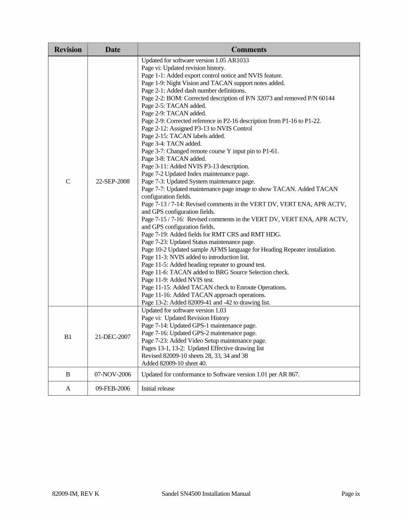
5. High Resolution Digital Output from a Mid-Continent 4305 series DG with gyro valid output, flux gate 10 Vac Fluxgate Excitation and Internal 26Vac Inverter (internal slaving)
Internal slaving requires connection of the flux gate excitation to the SN4500 flux gate reference input P2-24. This input is used only to demodulate the flux gate signals.
DG’s with XYZ bootstrap output requires the master 400Hz inverter to be connected to the SN4500 400Hz reference input on P1-22. This input is used to lock all 400Hz inputs on P1 and 400Hz outputs in the SN4500. This input presents less than 1mA loading to the source.
Follow the information on the installation drawings, and plan to set up the appropriate compass selections on the compass system maintenance page.
Internal slaving does not require the use of an external slaving accessory. Compass calibration is performed using the SN4500 Compass maintenance page. The SN4500 will provide standby heading operation from the flux gate alone in the event of directional gyro (DG) failure.
The SN4500 has a 3-wire ARINC 407 synchro bootstrap compass output if required which is capable of driving electronic loads.
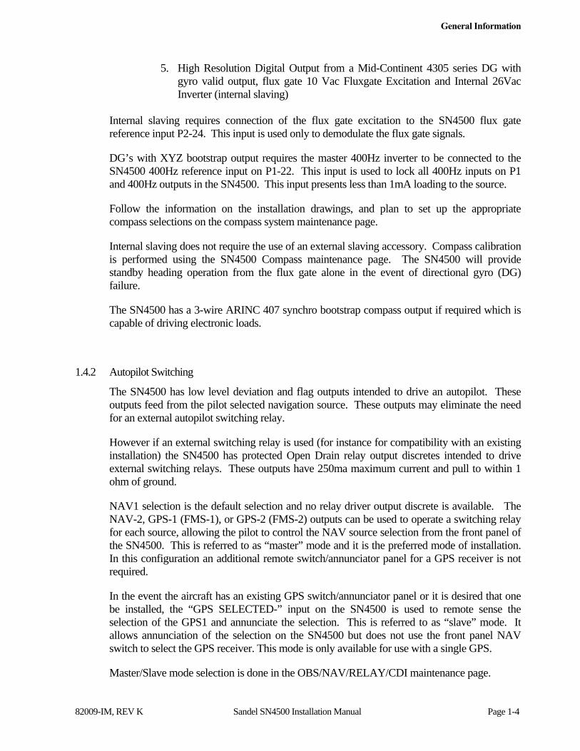
1.4.2 Autopilot Switching
The SN4500 has low level deviation and flag outputs intended to drive an autopilot. These outputs feed from the pilot selected navigation source. These outputs may eliminate the need for an external autopilot switching relay.
However if an external switching relay is used (for instance for compatibility with an existing installation) the SN4500 has protected Open Drain relay output discretes intended to drive external switching relays. These outputs have 250ma maximum current and pull to within 1 ohm of ground.
NAV1 selection is the default selection and no relay driver output discrete is available. The NAV-2, GPS-1 (FMS-1), or GPS-2 (FMS-2) outputs can be used to operate a switching relay for each source, allowing the pilot to control the NAV source selection from the front panel of the SN4500. This is referred to as “master” mode and it is the preferred mode of installation. In this configuration an additional remote switch/annunciator panel for a GPS receiver is not required.
In the event the aircraft has an existing GPS switch/annunciator panel or it is desired that one be installed, the “GPS SELECTED-” input on the SN4500 is used to remote sense the selection of the GPS1 and annunciate the selection. This is referred to as “slave” mode. It allows annunciation of the selection on the SN4500 but does not use the front panel NAV switch to select the GPS receiver. This mode is only available for use with a single GPS.
Master/Slave mode selection is done in the OBS/NAV/RELAY/CDI maintenance page.
General Information
82009-IM, REV K Sandel SN4500 Installation Manual Page 1-5
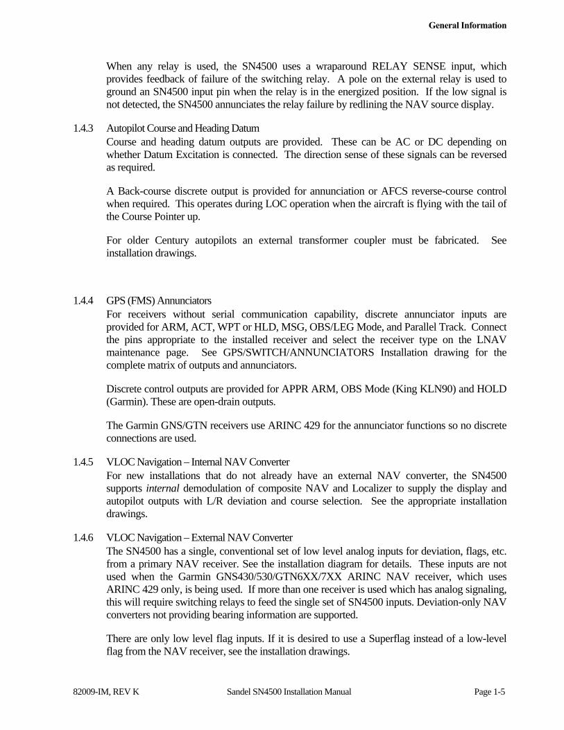
When any relay is used, the SN4500 uses a wraparound RELAY SENSE input, which provides feedback of failure of the switching relay. A pole on the external relay is used to ground an SN4500 input pin when the relay is in the energized position. If the low signal is not detected, the SN4500 annunciates the relay failure by redlining the NAV source display.
1.4.3 Autopilot Course and Heading Datum Course and heading datum outputs are provided. These can be AC or DC depending on whether Datum Excitation is connected. The direction sense of these signals can be reversed as required.
A Back-course discrete output is provided for annunciation or AFCS reverse-course control when required. This operates during LOC operation when the aircraft is flying with the tail of the Course Pointer up.
For older Century autopilots an external transformer coupler must be fabricated. See installation drawings.
1.4.4 GPS (FMS) Annunciators For receivers without serial communication capability, discrete annunciator inputs are provided for ARM, ACT, WPT or HLD, MSG, OBS/LEG Mode, and Parallel Track. Connect the pins appropriate to the installed receiver and select the receiver type on the LNAV maintenance page. See GPS/SWITCH/ANNUNCIATORS Installation drawing for the complete matrix of outputs and annunciators.
Discrete control outputs are provided for APPR ARM, OBS Mode (King KLN90) and HOLD (Garmin). These are open-drain outputs.
The Garmin GNS/GTN receivers use ARINC 429 for the annunciator functions so no discrete connections are used.
1.4.5 VLOC Navigation – Internal NAV Converter For new installations that do not already have an external NAV converter, the SN4500 supports internal demodulation of composite NAV and Localizer to supply the display and autopilot outputs with L/R deviation and course selection. See the appropriate installation drawings.
1.4.6 VLOC Navigation – External NAV Converter The SN4500 has a single, conventional set of low level analog inputs for deviation, flags, etc. from a primary NAV receiver. See the installation diagram for details. These inputs are not used when the Garmin GNS430/530/GTN6XX/7XX ARINC NAV receiver, which uses ARINC 429 only, is being used. If more than one receiver is used which has analog signaling, this will require switching relays to feed the single set of SN4500 inputs. Deviation-only NAV converters not providing bearing information are supported.
There are only low level flag inputs. If it is desired to use a Superflag instead of a low-level flag from the NAV receiver, see the installation drawings.
General Information
82009-IM, REV K Sandel SN4500 Installation Manual Page 1-6
Optional ILS lockout of the GPS selection is provided by an ILS Energize 1/2 input pins. This feature can be disabled on the NAV maintenance page. In the Master mode this will cause the SN4500 to revert to and annunciate NAV1 when an ILS is tuned on NAV1, or NAV2 when an ILS is tuned on NAV2. Disabling of ILS lockout is called for when the customer does not want ILS lockout operation, or when a GPS receiver with vertical guidance is used to drive the ILS Energize pin during GPS operation. In this situation NAV1/GPS1 use ILS Energize 1, and NAV2/GPS 2 use ILS Energize 2 to display vertical guidance.
For analog receivers, two types of resolvers are supported.
a) An electronic OBS resolver with rotor input and SIN/COS outputs is provided. An associated DC reference pin must be connected to the stator low-side connection of the NAV receiver. This may be ground but may also be a DC reference voltage of approximately 4.5vdc. WARNING: You must check the NAV receiver wiring before installation planning and before applying power to the system to prevent NAV receiver damage from inadvertent miswiring. Refer to the Sandel installation drawing.
This resolver will operate from 30Hz to 500Hz and is calibrated in the NAV maintenance page.
1.4.7 400Hz Differential Resolver A single electronic 400Hz differential resolver is provided for use with 400Hz receivers such as Collins VIR-30A. This interconnect uses SIN/COS inputs (Z-ground referenced) and SIN/COS outputs (Z-ground referenced).
1.4.8 Marker Beacon Three inputs are provided for a Marker Beacon repeater. These are DC level-sensitive inputs. The thresholds and logic levels are adjusted by selection of the appropriate equipment type on the MKR maintenance page. Lamp load resistors are internal.
The SN4500 can also monitor label 222 when marker beacon data is provided from an ARINC 429 source.
1.4.9 Bearing Pointers (VOR, ADF, and TACAN) The bearing pointers can derive their information from any of the connected navigation receivers, including two composite NAV inputs, ADF’s, TACAN’s and the long range navigation receivers through the serial ports.
ADF’s can be connected as ARINC 407 synchro or DC SIN/COS inputs. See the installation drawings for interconnection data and select the appropriate format from the ADF maintenance page.
The composite NAV inputs accept standard 0.5v ARINC inputs. For 3v inputs a series resistor is required, please see the appropriate installation drawing. Selection of 0/180 phase is made by the appropriate maintenance page calibration.
1.4.10 ARINC Channels
General Information
82009-IM, REV K Sandel SN4500 Installation Manual Page 1-7
The SN4500 contains universal inputs capable of communicating with ARINC 429, ARINC 419, RS232 and Analog. All equipment capable of ARINC compatibility (such as GPS/FMS, Navigation, Traffic, etc) can be directly connected to the appropriate signal input. There are a total of 17 compatible ARINC inputs.
1.4.11 DME Interface DME inputs support ARINC 429, ARINC 568, King serial, or single analog (40mV/mile) inputs.
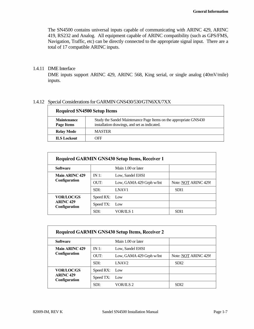
1.4.12 Special Considerations for GARMIN GNS430/530/GTN6XX/7XX
Required SN4500 Setup Items
Maintenance Page Items
Study the Sandel Maintenance Page Items on the appropriate GNS430 installation drawings, and set as indicated.
Relay Mode MASTER
ILS Lockout OFF
Required GARMIN GNS430 Setup Items, Receiver 1
Software Main 1.00 or later
Main ARINC 429 Configuration
IN 1: Low, Sandel EHSI
OUT: Low, GAMA 429 Grph w/Int Note: NOT ARINC 429!
SDI: LNAV1 SDI1
VOR/LOC/GS ARINC 429 Configuration
Speed RX: Low
Speed TX: Low
SDI: VOR/ILS 1 SDI1
Required GARMIN GNS430 Setup Items, Receiver 2
Software Main 1.00 or later
Main ARINC 429 Configuration
IN 1: Low, Sandel EHSI
OUT: Low, GAMA 429 Grph w/Int Note: NOT ARINC 429!
SDI: LNAV2 SDI2
VOR/LOC/GS ARINC 429 Configuration
Speed RX: Low
Speed TX: Low
SDI: VOR/ILS 2 SDI2

General Information
82009-IM, REV K Sandel SN4500 Installation Manual Page 1-8
Required Garmin GTN 6xx/7xx Setup Items, Receiver 1
Software Main 5.0 or later
Main ARINC 429 Configuration
IN 1: EFIS Format 4
OUT: GAMA Format 3
SDI LNAV1 SDI1
VOR/LOC/GS ARINC 429 Configuration
Speed RX: Low or High as needed
Speed TX: Low or High as needed
SDI: VOR/ILS1 SDI1
Required Garmin GTN 6xx/7xx Setup Items, Receiver 2
Software Main 5.0 or later
Main ARINC 429 Configuration
IN 1: EFIS Format 4
OUT: GAMA Format 3
SDI LNAV1 SDI2
VOR/LOC/GS ARINC 429 Configuration
Speed RX: Low or High as needed
Speed TX: Low or High as needed
SDI: VOR/ILS2 SDI2
1.4.13 Special Considerations for GNS XLS Users
The SN4500 will display the arc segment on a published approach incorporating a DME arc in one of three different ways depending on the arc style configuration selected in the GNS-XLS. Consult the GNS-XLS installation manual for configuration details.
Configuring the GNS-XLS for:
ARC Style ARC Display
ARC TO AT END DME arcs are displayed in magenta when it is the active portion of the flight plan otherwise they will be displayed in white.
ARC TO ON ARC DME arcs are always displayed in white.
ARC AS GAP DME arcs are not displayed. A straight line will be drawn from the beginning of the ARC to the waypoint at the end of the ARC. The color of the line will be magenta when it is the active portion of the flight plan otherwise it will be displayed in white.
General Information
82009-IM, REV K Sandel SN4500 Installation Manual Page 1-9
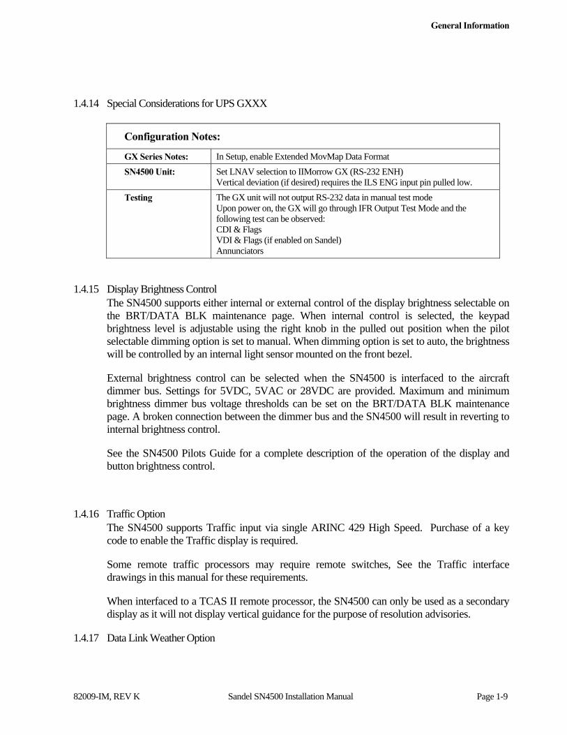
1.4.14 Special Considerations for UPS GXXX
Configuration Notes:
GX Series Notes: In Setup, enable Extended MovMap Data Format
SN4500 Unit: Set LNAV selection to IIMorrow GX (RS-232 ENH) Vertical deviation (if desired) requires the ILS ENG input pin pulled low.
Testing The GX unit will not output RS-232 data in manual test mode Upon power on, the GX will go through IFR Output Test Mode and the following test can be observed: CDI & Flags VDI & Flags (if enabled on Sandel) Annunciators
1.4.15 Display Brightness Control The SN4500 supports either internal or external control of the display brightness selectable on the BRT/DATA BLK maintenance page. When internal control is selected, the keypad brightness level is adjustable using the right knob in the pulled out position when the pilot selectable dimming option is set to manual. When dimming option is set to auto, the brightness will be controlled by an internal light sensor mounted on the front bezel.
External brightness control can be selected when the SN4500 is interfaced to the aircraft dimmer bus. Settings for 5VDC, 5VAC or 28VDC are provided. Maximum and minimum brightness dimmer bus voltage thresholds can be set on the BRT/DATA BLK maintenance page. A broken connection between the dimmer bus and the SN4500 will result in reverting to internal brightness control.
See the SN4500 Pilots Guide for a complete description of the operation of the display and button brightness control.
1.4.16 Traffic Option The SN4500 supports Traffic input via single ARINC 429 High Speed. Purchase of a key code to enable the Traffic display is required.
Some remote traffic processors may require remote switches, See the Traffic interface drawings in this manual for these requirements.
When interfaced to a TCAS II remote processor, the SN4500 can only be used as a secondary display as it will not display vertical guidance for the purpose of resolution advisories.
1.4.17 Data Link Weather Option
General Information
82009-IM, REV K Sandel SN4500 Installation Manual Page 1-10
The SN4500 supports Flight Information Services-Broadcast (FIS-B) data link weather (precipitation and lightning), input via a single RS-232 Input from a WSI Data Link receiver. Purchase of a key code to enable the weather display is required. See the WSI Data Link Receiver interface drawings in this manual for interface wiring requirements.
The SN4500 can be configured to operate as the sole weather display or a listener when another display is installed and configured to command the WSI receiver. When the SN4500 is the sole display, the WSI receiver RS-232 interface must be configured as “NO FLOW CONTROL”, see the WSI receiver manual for details regarding receiver configuration.
1.4.18 Night Vision Support Option For NVIS capable units NVIS mode is enabled by a closure to ground through an external toggle switch or maintained pushbutton switch. NVIS mode is annunciated onscreen so an external annunciator is not required.
The input will always pull up to the de-activated state when disconnected.
1.4.19 TACAN Option The SN4500 supports TACAN input via ARINC 419, ARINC 429, and Arinc 407 Synchro (XYZ). A TACAN key code is not required for maintenance page setup however, purchase of a key code to enable the TACAN display is required. When configured, TCN will not appear as a NAV source selection or on the bearing pointer source list if the TACAN key is not valid. See the TACAN interface drawings in this manual for interface wiring requirements.
1.4.20 Reversionary Attitude Option The SN4500 supports a Reversionary Attitude Display when interfaced to an Attitude Heading Reference System supplying Roll, Pitch, Heading, and lateral acceleration data via Arinc 429. An optional key code is required to enable this feature. See the Reversionary Control interface drawing in this manual for interface wiring requirements. This option is not available when the SN4500 is interfaced to an analog DME.
1.4.21 Roll Steering Option An optional Roll Steering option has been added with software version 4.04 or later which adds the capability for the GPS navigator to precisely fly a GPS flight plan including high angle course intercepts and holding patterns. The GPS must support sending Arinc 429 label 121. There are no additional installation considerations to the autopilot other than previously mentioned. An optional key code is required to enable this feature.

General Information
82009-IM, REV K Sandel SN4500 Installation Manual Page 1-11
1.5 Disclaimer
Sandel Avionics does not assume any risk for nor accept any responsibility for the interface descriptions contained within this Installation Manual. It is the responsibility of the installer to ensure that such equipment is compatible with the SN4500 as described, and to ensure that the installation of the SN4500 is accomplished with such equipment using the specific equipment manufacturer’s installation and technical instructions. No other representations are expressed herein.
Technical Information
82009-IM, REV K Sandel SN4500 Installation Manual Page 2-1
2 Technical Information
2.1 General
The SN4500 is enclosed in an ARINC 408, 4ATI form factor enclosure and is mounted to an instrument panel using a standard ATI clamp.
The SN4500 operates on an input voltage from 22 to 33 Volts DC, nominal 40 watts. 26 Volts AC 400 Hertz reference excitation inputs with a current requirement of less than 1 milliampere are required when the functions of AC synchro inputs or outputs are required for use with peripheral equipment. These reference excitation signals must be obtained from the correct aircraft inverter source. A third inverter input ‘Datum Excitation’ is available and is specifically used in situations where the autopilot uses an additional inverter or the autopilot inverter frequency is higher than 400Hz.
The following section describes the technical characteristics that include the appliance approval basis, physical and electrical properties, electrical connector pin allocation which details function and gradient or equipment protocol, and ARINC label support. Also included is the description of the SN4500 installation components, other equipment and installation requirements. A review of the installation approval procedures is provided for filing with authorities.
2.2 Part Numbers
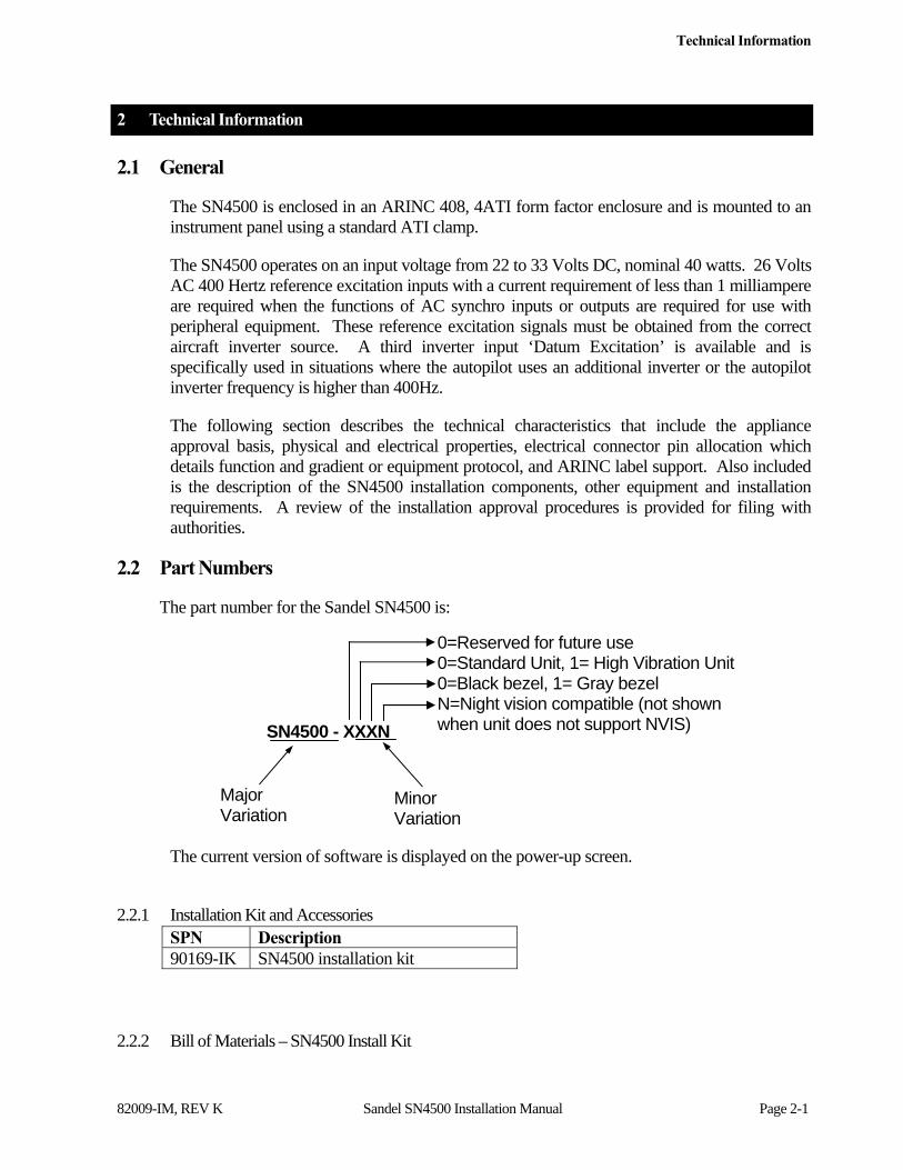
The part number for the Sandel SN4500 is:
The current version of software is displayed on the power-up screen.
2.2.1 Installation Kit and Accessories
SPN Description 90169-IK SN4500 installation kit
2.2.2 Bill of Materials – SN4500 Install Kit
0=Reserved for future use 0=Standard Unit, 1= High Vibration Unit 0=Black bezel, 1= Gray bezel N=Night vision compatible (not shown when unit does not support NVIS) SN4500 - XXXN
Major Variation
Minor Variation
Technical Information
82009-IM, REV K Sandel SN4500 Installation Manual Page 2-2
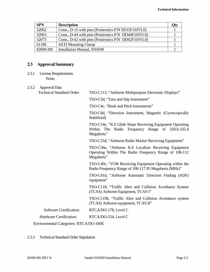
SPN Description Qty 32062 Conn., D-15 with pins (Positronics P/N SD15F10JVL0) 1 32063 Conn., D-44 with pins (Positronics P/N DD44F10JVL0) 1 32073 Conn., D-62 with pins (Positronics P/N DD62F10JVL0) 1 61186 4ATI Mounting Clamp 1 82009-IM Installation Manual, SN4500 1
2.3 Approval Summary
2.3.1 License Requirements None.
2.3.2 Approval Data Technical Standard Order: TSO-C113, “Airborne Multipurpose Electronic Displays”
TSO-C3d, “Turn and Slip Instrument”
TSO-C4c, “Bank and Pitch Instruments”
TSO-C6d, “Direction Instrument, Magnetic (Gyroscopically Stabilized)
TSO-C34e, “ILS Glide Slope Receiving Equipment Operating Within The Radio Frequency Range of 328.6-335.4 Megahertz”
TSO-C35d, “Airborne Radio Marker Receiving Equipment”
TSO-C36e, “Airborne ILS Localizer Receiving Equipment Operating Within The Radio Frequency Range of 108-112 Megahertz”
TSO-C40c, “VOR Receiving Equipment Operating within the Radio Frequency Range of 108-117.95 Megahertz (MHz)”
TSO-C41d, “Airborne Automatic Direction Finding (ADF) equipment”
TSO-C118, “Traffic Alert and Collision Avoidance System (TCAS) Airborne Equipment, TCAS I”
TSO-C119b, “Traffic Alert and Collision Avoidance system (TCAS) Airborne equipment, TCAS II”
Software Certification: RTCA/DO-178, Level C
Hardware Certification: RTCA/DO-254, Level C
Environmental Categories: RTCA/DO-160E
2.3.3 Technical Standard Order Stipulation
Technical Information
82009-IM, REV K Sandel SN4500 Installation Manual Page 2-3
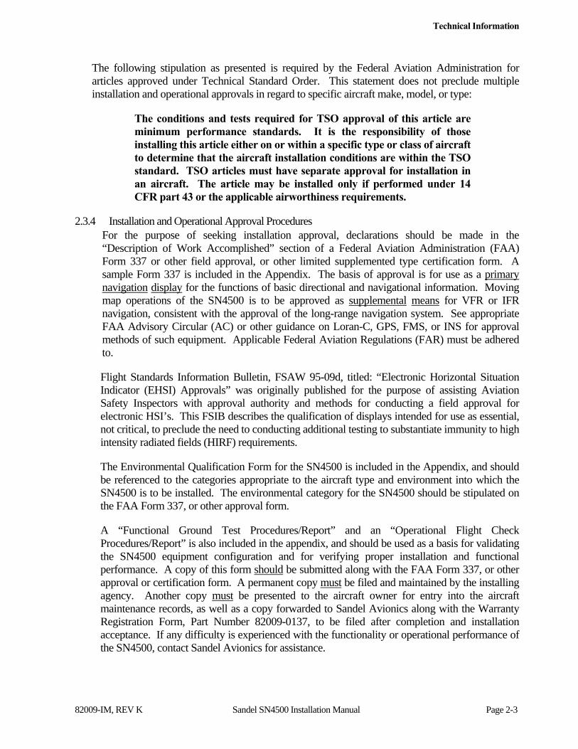
The following stipulation as presented is required by the Federal Aviation Administration for articles approved under Technical Standard Order. This statement does not preclude multiple installation and operational approvals in regard to specific aircraft make, model, or type:
The conditions and tests required for TSO approval of this article are minimum performance standards. It is the responsibility of those installing this article either on or within a specific type or class of aircraft to determine that the aircraft installation conditions are within the TSO standard. TSO articles must have separate approval for installation in an aircraft. The article may be installed only if performed under 14 CFR part 43 or the applicable airworthiness requirements.
2.3.4 Installation and Operational Approval Procedures For the purpose of seeking installation approval, declarations should be made in the “Description of Work Accomplished” section of a Federal Aviation Administration (FAA) Form 337 or other field approval, or other limited supplemented type certification form. A sample Form 337 is included in the Appendix. The basis of approval is for use as a primary navigation display for the functions of basic directional and navigational information. Moving map operations of the SN4500 is to be approved as supplemental means for VFR or IFR navigation, consistent with the approval of the long-range navigation system. See appropriate FAA Advisory Circular (AC) or other guidance on Loran-C, GPS, FMS, or INS for approval methods of such equipment. Applicable Federal Aviation Regulations (FAR) must be adhered to.
Flight Standards Information Bulletin, FSAW 95-09d, titled: “Electronic Horizontal Situation Indicator (EHSI) Approvals” was originally published for the purpose of assisting Aviation Safety Inspectors with approval authority and methods for conducting a field approval for electronic HSI’s. This FSIB describes the qualification of displays intended for use as essential, not critical, to preclude the need to conducting additional testing to substantiate immunity to high intensity radiated fields (HIRF) requirements.
The Environmental Qualification Form for the SN4500 is included in the Appendix, and should be referenced to the categories appropriate to the aircraft type and environment into which the SN4500 is to be installed. The environmental category for the SN4500 should be stipulated on the FAA Form 337, or other approval form.
A “Functional Ground Test Procedures/Report” and an “Operational Flight Check Procedures/Report” is also included in the appendix, and should be used as a basis for validating the SN4500 equipment configuration and for verifying proper installation and functional performance. A copy of this form should be submitted along with the FAA Form 337, or other approval or certification form. A permanent copy must be filed and maintained by the installing agency. Another copy must be presented to the aircraft owner for entry into the aircraft maintenance records, as well as a copy forwarded to Sandel Avionics along with the Warranty Registration Form, Part Number 82009-0137, to be filed after completion and installation acceptance. If any difficulty is experienced with the functionality or operational performance of the SN4500, contact Sandel Avionics for assistance.

Technical Information
82009-IM, REV K Sandel SN4500 Installation Manual Page 2-4
2.4 Physical, and Electrical Properties
2.4.1 Physical Dimensions
Form Factor: 4ATI (ARINC 408) Width: 3.975 in. (10.10 cm.) Height: 3.975 in. (10.10 cm.) Length: 10.20 in. (25.91 cm.) overall flush to bezel;
9.87 in (25.07 cm) measured from rear of bezel. Weight: 3.5 lbs. (1.6 Kg.) CG: 4.7” from rear of bezel. ATI Clamp: Sandel Avionics P/N 61186 or equivalent. Cooling Requirements: Internal fan requiring ambient air at fan input.
2.4.2 Summary Operational Characteristics
Temperature Altitude: -20° C to +70° C – up to 55,000 feet Power Inputs: 28 Vdc @ 1.4A nominal (40 watts)
2.5 Connector Summary
The SN4500 is designed to interface and operate with several generations of avionics equipment. It is compatible with DC analog and/or ARINC standard synchro and serial digital signals, as well as industry standard and adopted AC and DC sine, cosine, and discrete input and output voltages. The SN4500 design and operation is optimized for efficient adaptability to both new and existing avionics equipment and systems.
The lists on the following pages reflect the configurable input and output signal types for various equipment types. See “SETUP PROCEDURES” on page 4-1 for more information on maintenance setup pages.
Technical Information
82009-IM, REV K Sandel SN4500 Installation Manual Page 2-5
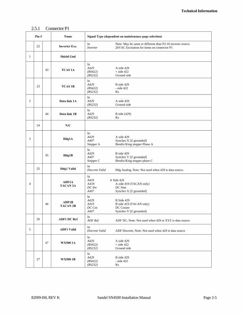
2.5.1 Connector P1
Pin # Name Signal Type (dependent on maintenance page selection)
22 Inverter Exc. In Note: May be same or different than P2-16 inverter source. Inverter 26VAC Excitation for items on connector P1
1 Shield Gnd
43 TCAS 1A
In A429 A side 429 (RS422) + side 422 (RS232) Ground side
23 TCAS 1B
In A429 B side 429 (RS422) - side 422 (RS232) Rx
2 Data link 1A In A429 A side 429 (RS232) Ground side
44 Data link 1B In A429 B side (429) (RS232) Rx
24 N/C
3 Hdg1A
In A429 A side 429 A407 Synchro X [Z grounded] Stepper A Bendix/King stepper Phase A
45 Hdg1B
In A429 B side 429 A407 Synchro Y [Z grounded] Stepper C Bendix/King stepper phase C
25 Hdg1 Valid In Discrete Valid Hdg Analog, Note: Not used when 429 is data source.
4 ADF1A TACAN 2A
In A429 A Side 429 A419 A side 419 (TACAN only) DC Sin DC Sine A407 Synchro X [Z grounded]
46 ADF1B
TACAN 2B
In A429 B Side 429 A419 B side 419 (TACAN only) DC Cos DC Cosine A407 Synchro Y [Z grounded]
26 ADF1 DC Ref In ADF Ref ADF DC, Note: Not used when 429 or XYZ is data source.
5 ADF1 Valid In Discrete Valid ADF Discrete, Note: Not used when 429 is data source
47 WX500 1A
In A429 A side 429 (RS422) + side 422 (RS232) Ground side
27 WX500 1B
In A429 B side 429 (RS422) - side 422 (RS232) Rx
Technical Information
82009-IM, REV K Sandel SN4500 Installation Manual Page 2-6
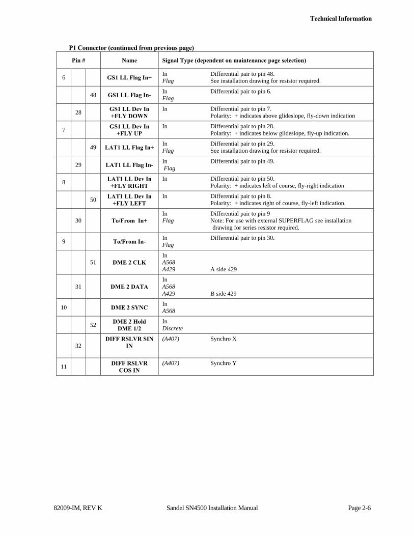
P1 Connector (continued from previous page)
Pin # Name Signal Type (dependent on maintenance page selection)
6 GS1 LL Flag In+ In Differential pair to pin 48. Flag See installation drawing for resistor required.
48 GS1 LL Flag In- In Differential pair to pin 6. Flag
28 GS1 LL Dev In +FLY DOWN
In Differential pair to pin 7. Polarity: + indicates above glideslope, fly-down indication
7 GS1 LL Dev In
+FLY UP In Differential pair to pin 28. Polarity: + indicates below glideslope, fly-up indication.
49 LAT1 LL Flag In+ In Differential pair to pin 29. Flag See installation drawing for resistor required.
29 LAT1 LL Flag In- In Differential pair to pin 49. Flag
8 LAT1 LL Dev In
+FLY RIGHT In Differential pair to pin 50. Polarity: + indicates left of course, fly-right indication
50 LAT1 LL Dev In
+FLY LEFT In Differential pair to pin 8. Polarity: + indicates right of course, fly-left indication.
30 To/From In+ In Differential pair to pin 9 Flag Note: For use with external SUPERFLAG see installation
drawing for series resistor required.
9 To/From In- In Differential pair to pin 30. Flag
51 DME 2 CLK In A568 A429 A side 429
31 DME 2 DATA In A568 A429 B side 429
10 DME 2 SYNC In A568
52 DME 2 Hold DME 1/2
In Discrete
32 DIFF RSLVR SIN
IN
(A407) Synchro X
11 DIFF RSLVR COS IN
(A407) Synchro Y
Technical Information
82009-IM, REV K Sandel SN4500 Installation Manual Page 2-7
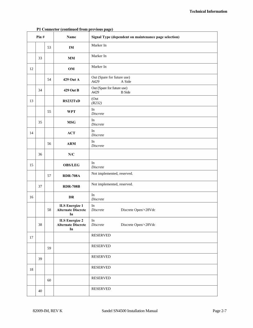
P1 Connector (continued from previous page)
Pin # Name Signal Type (dependent on maintenance page selection)
53 IM Marker In
33 MM Marker In
12 OM Marker In
54 429 Out A Out (Spare for future use) A429 A Side
34 429 Out B Out (Spare for future use) A429 B Side
13 RS232TxD (Out (R232)
55 WPT In Discrete
35 MSG In Discrete
14 ACT In Discrete
56 ARM In Discrete
36 N/C
15 OBS/LEG In Discrete
57 RDR-708A Not implemented, reserved.
37 RDR-708B Not implemented, reserved.
16 DR In Discrete
58 ILS Energize 1
Alternate Discrete In
In Discrete Discrete Open/+28Vdc
38 ILS Energize 2
Alternate Discrete In
In Discrete Discrete Open/+28Vdc
17 RESERVED
59 RESERVED
39 RESERVED
18 RESERVED
60 RESERVED
40 RESERVED
Technical Information
82009-IM, REV K Sandel SN4500 Installation Manual Page 2-8
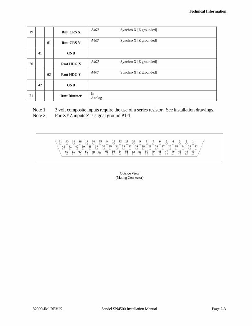
19 Rmt CRS X A407 Synchro X [Z grounded]
61 Rmt CRS Y A407 Synchro X [Z grounded]
41 GND
20 Rmt HDG X A407 Synchro X [Z grounded]
62 Rmt HDG Y A407 Synchro X [Z grounded]
42 GND
21 Rmt Dimmer In Analog
Note 1. 3 volt composite inputs require the use of a series resistor. See installation drawings. Note 2: For XYZ inputs Z is signal ground P1-1.
Outside View
(Mating Connector)
15
36
56
14
35
55
13
34
54
12
33
53
11
32
52
10
31
51
9
30
50
8
29
49
7
28
48
1
22
6
27
47
5
26
46
4
25
45
3
24
44
2
23
43
21
42
62
20
41
61
19
40
60
18
39
59
17
38
58
16
37
57

Technical Information
82009-IM, REV K Sandel SN4500 Installation Manual Page 2-9
2.5.2 Connector P2
Pin # Name Signal Type (dependent on maintenance page selection)
16 Inverter Exc. In Note: May be same or different than P1-22 inverter source. Inverter 26Vac Excitation for items on connector P2
1 Shield Gnd
31 FMS 1A
In A429 A side 429 (RS422) + side 422 (RS232) Ground side
17 FMS 1B
In A429 B side 429 (RS422) - side 422 (RS232) Rx
2 FMS 2A In A429 A side 429 (RS232) Ground Side
32 FMS 2B In A429 B side 429 (RS232) Rx
18 ILS Energize1
Discrete In HDG X Alternate
In Discrete Discrete Open/Gnd or Open/+28Vdc A407 Synchro X [Z grounded]
3 NAV1A In A429 A side 429 A710 Composite Video
33 NAV1B In A429 B side 429
19 ILS Energize2
Discrete In HDG Y Alternate
In Discrete Discrete Open/Gnd or Open/+28Vdc A407 Synchro Y [Z grounded]
4 ADF 2A
TACAN 1A
In A429 A side 429 A419 A Side 419 (TACAN only) DC Sin DC Sine (ADF only) A407 Synchro X [Z grounded]
34 ADF 2B TACAN 1B
In A429 B side 429 A419 B Side 419 (TACAN only) DC Cos DC Cosine (ADF only) A407 Synchro Y [Z grounded]
20 ADF 2 DC Ref In ADF Ref ADF DC, Note: Not used when 429 or XYZ is data source.
5 ADF 2 Valid In Discrete Valid ADF Discrete, Note: Not used when 429 is data source
35 NAV2A In A429 A side 429 A710 Composite Video
21 NAV2B
In A429 B side 429

Technical Information
82009-IM, REV K Sandel SN4500 Installation Manual Page 2-10
P2 Connector (continued from previous page)
Pin # Name Signal Type (dependent on maintenance page selection)
6 DME 1 DATA
In A568 Analog DC+ A429 A side 429
36 DME 1 CLK
In A568 Analog DC- A429 B side 429
22 DME 1 SYNC In A568
7 DME 1 Hold In Discrete
37 OBS Resolver DC
Ref In Resolver DC
23 OBS Resolver H In Resolver H
8 OBS Resolver
X/Sin out Out Resolver Out
38 OBS Resolver
Y/Cos out Out Resolver Out
24 Fluxgate
Excitation In Fluxgate Excitation
9 Fluxgate X In
39 Fluxgate Y In
25 Fluxgate Z (Gnd) In
10 Hdg Crs/Datum Excitation
In 3rd inverter input used specifically if autopilot inverter is not inverter connected to P1-22 or is not 400Hz
40 Course Datum Out Locked to P1-22 or P2-10
26 Hdg Datum Out Locked to P1-22 or P2-10
11 Hdg X Out Out Bootstrap, locked to inverter on P1
Technical Information
82009-IM, REV K Sandel SN4500 Installation Manual Page 2-11
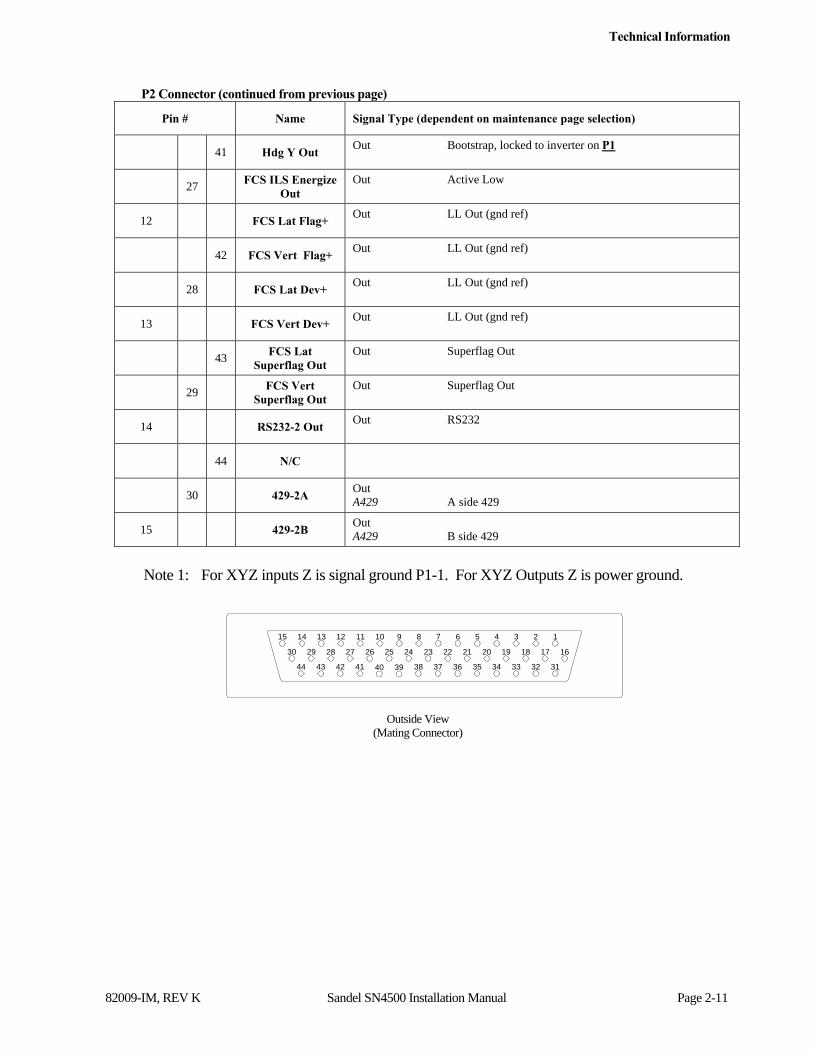
P2 Connector (continued from previous page)
Pin # Name Signal Type (dependent on maintenance page selection)
41 Hdg Y Out Out Bootstrap, locked to inverter on P1
27 FCS ILS Energize
Out Out Active Low
12 FCS Lat Flag+ Out LL Out (gnd ref)
42 FCS Vert Flag+ Out LL Out (gnd ref)
28 FCS Lat Dev+ Out LL Out (gnd ref)
13 FCS Vert Dev+ Out LL Out (gnd ref)
43 FCS Lat
Superflag Out Out Superflag Out
29 FCS Vert
Superflag Out Out Superflag Out
14 RS232-2 Out Out RS232
44 N/C
30 429-2A Out A429 A side 429
15 429-2B Out A429 B side 429
Note 1: For XYZ inputs Z is signal ground P1-1. For XYZ Outputs Z is power ground.
15
30
44
14
29
43
13
28
42
12
27
41
11
26
40
10
25
39
9
24
38
8
23
37
7
22
36
1
16
6
21
35
5
20
34
4
19
33
3
18
32
2
17
31
Outside View
(Mating Connector)
Technical Information
82009-IM, REV K Sandel SN4500 Installation Manual Page 2-12
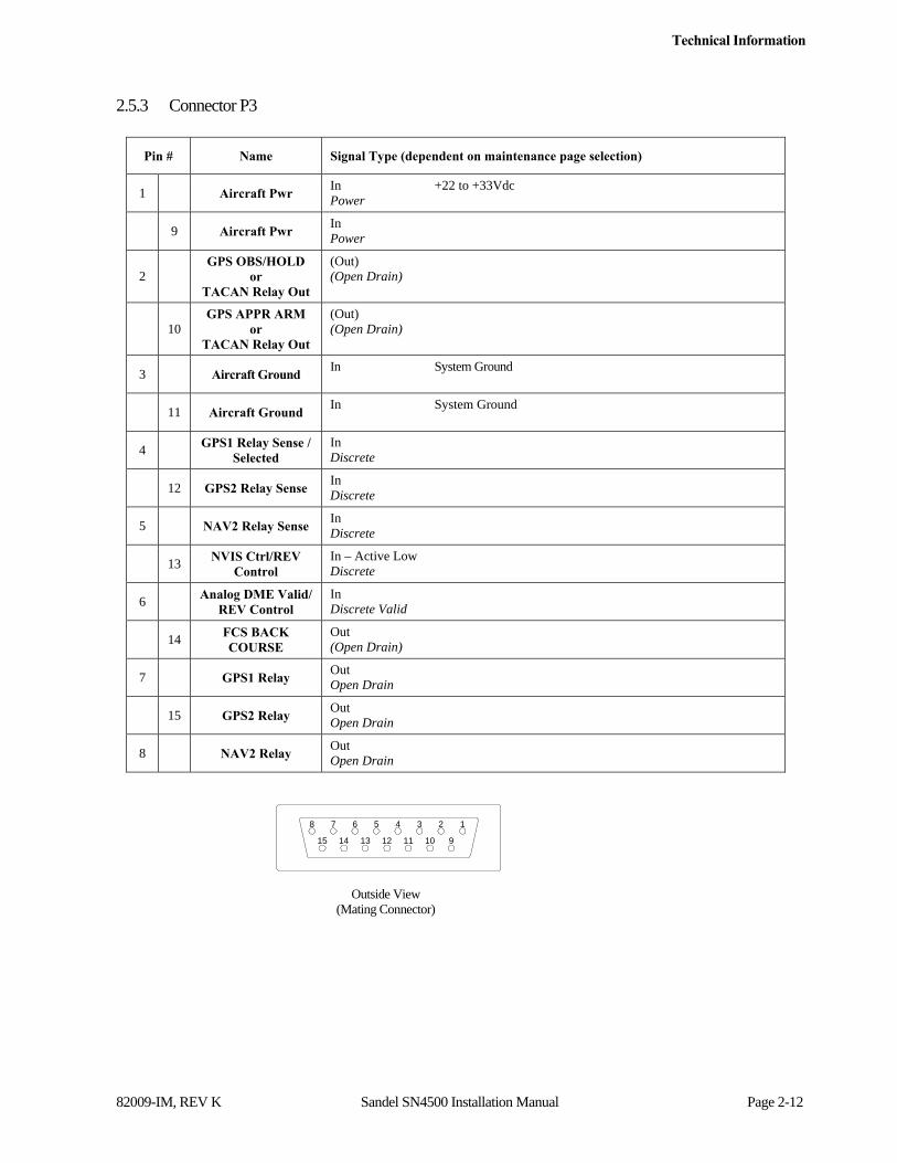
2.5.3 Connector P3
Pin # Name Signal Type (dependent on maintenance page selection)
1 Aircraft Pwr In +22 to +33Vdc Power
9 Aircraft Pwr In Power
2 GPS OBS/HOLD
or TACAN Relay Out
(Out) (Open Drain)
10 GPS APPR ARM
or TACAN Relay Out
(Out) (Open Drain)
3 Aircraft Ground In System Ground
11 Aircraft Ground In System Ground
4 GPS1 Relay Sense /
Selected In Discrete
12 GPS2 Relay Sense In Discrete
5 NAV2 Relay Sense In Discrete
13 NVIS Ctrl/REV
Control In – Active Low Discrete
6 Analog DME Valid/
REV Control In Discrete Valid
14 FCS BACK COURSE
Out (Open Drain)
7 GPS1 Relay Out Open Drain
15 GPS2 Relay Out Open Drain
8 NAV2 Relay Out Open Drain
8
15
7
14
16
13
5
12
4
11
3
10
2
9
Outside View (Mating Connector)
Technical Information
82009-IM, REV K Sandel SN4500 Installation Manual Page 2-13
2.5.4 Configuration Module Connector
Accepts SN4500 Configuration Module.
The configuration module holds all installation data and is specific to the aircraft. If the SN4500 is swapped, re-using the configuration module will automatically reconfigure the new unit to the original aircraft configuration.
The SN4500 may be operated with or without a configuration module connected. If no configuration module is present the SN4500 will operate but the pilot will receive an advisory message.

Technical Information
82009-IM, REV K Sandel SN4500 Installation Manual Page 2-14
2.5.5 Signal Characteristics Table
Inputs
Signal Type Nom Range Absolute Max Note 3 Z (Ω – Power Off)
A429 +/- 5Vdc 100Vdc >100K
A568 0 / +10Vdc 100Vdc >100K
RS232 +/- 10Vdc 100Vdc >100K
RS422 +/- 5Vdc 100Vdc >100K
A710 (ILS) .5Vac rms +/- 20% 70Vac >100K
A711 (VOR) .5Vac rms +/- 20% 70Vac >100K
A407 0 to 11.8Vac 70Vac >100K
DC SIN/COS +/- 20Vdc 100Vdc >100K
A407 (AC Synchro) 11.8Vac rms +/- 20% 100Vdc >100K
ADF_REF 10Vdc +/- 50% 60Vdc >100K
Alt DC Coarse 0 to 15Vdc 100Vdc >100K
Analog DME 0 to 8Vdc 75VdcNote 5 180K
Discrete Valid (High) >14.0VdcNote 4 60Vdc >500K
Discrete Valid (Low) <3.5Vdc Note 4 40Vdc >500K
Discrete (High) >1.2Vdc 32Vdc 50K
Discrete (Low) <8Vdc 32Vdc 50K
GS +/- 225mv FS 60Vdc >160KNote 2
GS Flag Unflagged > 225mv 60Vdc >160KNote 2
Inverter 26Vac rms 200Vac >50K
Power +22 to +33VdcNote 1 7Adc NA
Outputs
Signal Type Nom Range Absolute Max Note 3 Z (Ω – Power Off)
A429 +/- 5Vdc 70mAdc 2K (Minimum)
RS232 +/- 5Vdc 70mAdc 500 (Minimum)
A575 3.54 mA +/-1% 25mA 500
Open Drain 1 or High Impedance (over current protected)
250mAdc >350K

Technical Information
82009-IM, REV K Sandel SN4500 Installation Manual Page 2-15
Notes: 1. At +28Vdc, nominal current is 1.4Adc, 1 minute after start up. 2. Power On Load = 60.4K. For Glideslope there may need to be a 1K load somewhere else in the system to meet the receiver load
requirements. Check installation instructions for the interfaced receiver. 3. Outputs are protected against shorts to ground. Shorts to power supply may cause damage to components. 4. Discrete inputs actively pulled to 27.5v through 30k ohms when selected ‘active low’ or actively pulled to 0v through 30k ohms when
selected ‘active high’ in the maintenance pages. This ensures the input is in the ‘inactive’ state if an external connection fails. If interfacing to discrete signals which do not supply a “hard” 0v/27.5 volt transition, any input network may be used that ensures that the discrete input pin is not within 1.0v from its nominal threshold shown in the table either in the active or inactive state.
Technical Information
82009-IM, REV K Sandel SN4500 Installation Manual Page 2-16
2.6 ARINC 429
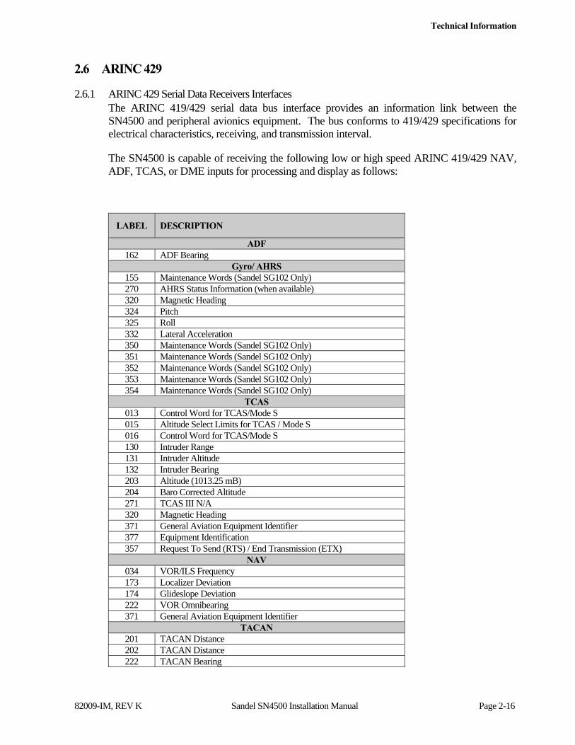
2.6.1 ARINC 429 Serial Data Receivers Interfaces The ARINC 419/429 serial data bus interface provides an information link between the SN4500 and peripheral avionics equipment. The bus conforms to 419/429 specifications for electrical characteristics, receiving, and transmission interval.
The SN4500 is capable of receiving the following low or high speed ARINC 419/429 NAV, ADF, TCAS, or DME inputs for processing and display as follows:
LABEL DESCRIPTION
ADF 162 ADF Bearing
Gyro/ AHRS 155 Maintenance Words (Sandel SG102 Only) 270 AHRS Status Information (when available) 320 Magnetic Heading 324 Pitch 325 Roll 332 Lateral Acceleration 350 Maintenance Words (Sandel SG102 Only) 351 Maintenance Words (Sandel SG102 Only) 352 Maintenance Words (Sandel SG102 Only) 353 Maintenance Words (Sandel SG102 Only) 354 Maintenance Words (Sandel SG102 Only)
TCAS 013 Control Word for TCAS/Mode S 015 Altitude Select Limits for TCAS / Mode S 016 Control Word for TCAS/Mode S 130 Intruder Range 131 Intruder Altitude 132 Intruder Bearing 203 Altitude (1013.25 mB) 204 Baro Corrected Altitude 271 TCAS III N/A 320 Magnetic Heading 371 General Aviation Equipment Identifier 377 Equipment Identification 357 Request To Send (RTS) / End Transmission (ETX)
NAV 034 VOR/ILS Frequency 173 Localizer Deviation 174 Glideslope Deviation 222 VOR Omnibearing 371 General Aviation Equipment Identifier
TACAN 201 TACAN Distance 202 TACAN Distance 222 TACAN Bearing
Technical Information
82009-IM, REV K Sandel SN4500 Installation Manual Page 2-17
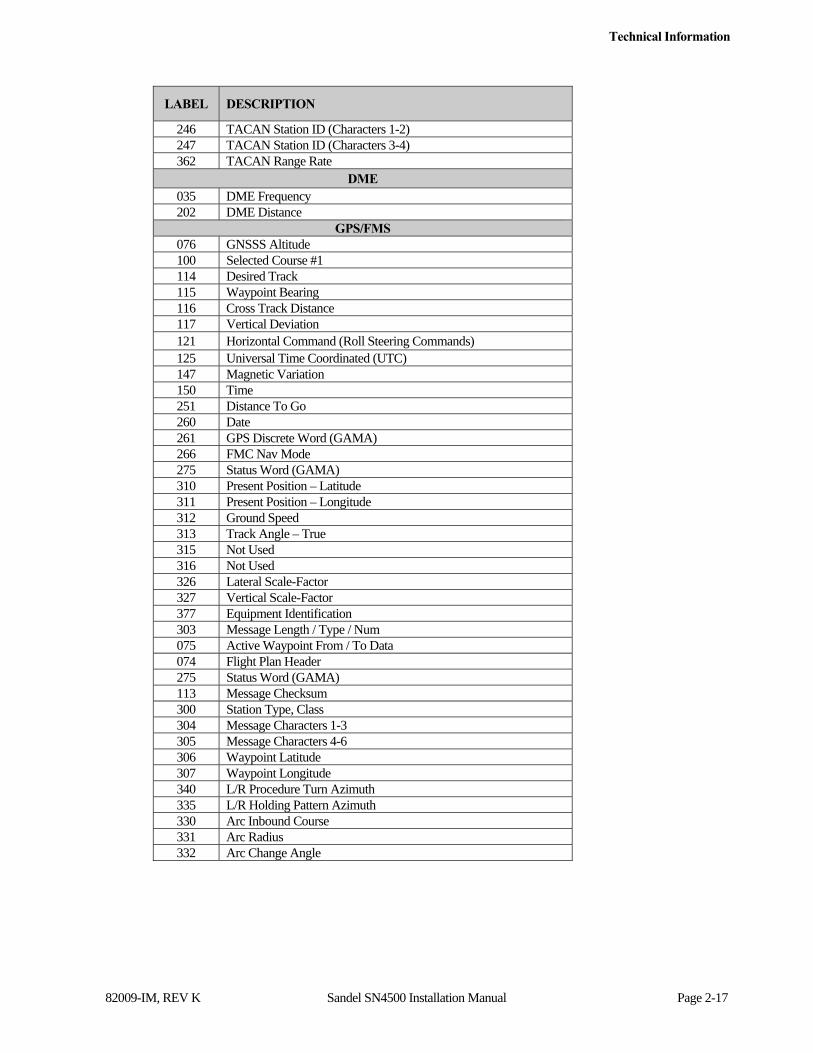
LABEL DESCRIPTION
246 TACAN Station ID (Characters 1-2) 247 TACAN Station ID (Characters 3-4) 362 TACAN Range Rate
DME 035 DME Frequency 202 DME Distance
GPS/FMS 076 GNSSS Altitude 100 Selected Course #1 114 Desired Track 115 Waypoint Bearing 116 Cross Track Distance 117 Vertical Deviation 121 Horizontal Command (Roll Steering Commands) 125 Universal Time Coordinated (UTC) 147 Magnetic Variation 150 Time 251 Distance To Go 260 Date 261 GPS Discrete Word (GAMA) 266 FMC Nav Mode 275 Status Word (GAMA) 310 Present Position – Latitude 311 Present Position – Longitude 312 Ground Speed 313 Track Angle – True 315 Not Used 316 Not Used 326 Lateral Scale-Factor 327 Vertical Scale-Factor 377 Equipment Identification 303 Message Length / Type / Num 075 Active Waypoint From / To Data 074 Flight Plan Header 275 Status Word (GAMA) 113 Message Checksum 300 Station Type, Class 304 Message Characters 1-3 305 Message Characters 4-6 306 Waypoint Latitude 307 Waypoint Longitude 340 L/R Procedure Turn Azimuth 335 L/R Holding Pattern Azimuth 330 Arc Inbound Course 331 Arc Radius 332 Arc Change Angle
Technical Information
82009-IM, REV K Sandel SN4500 Installation Manual Page 2-18
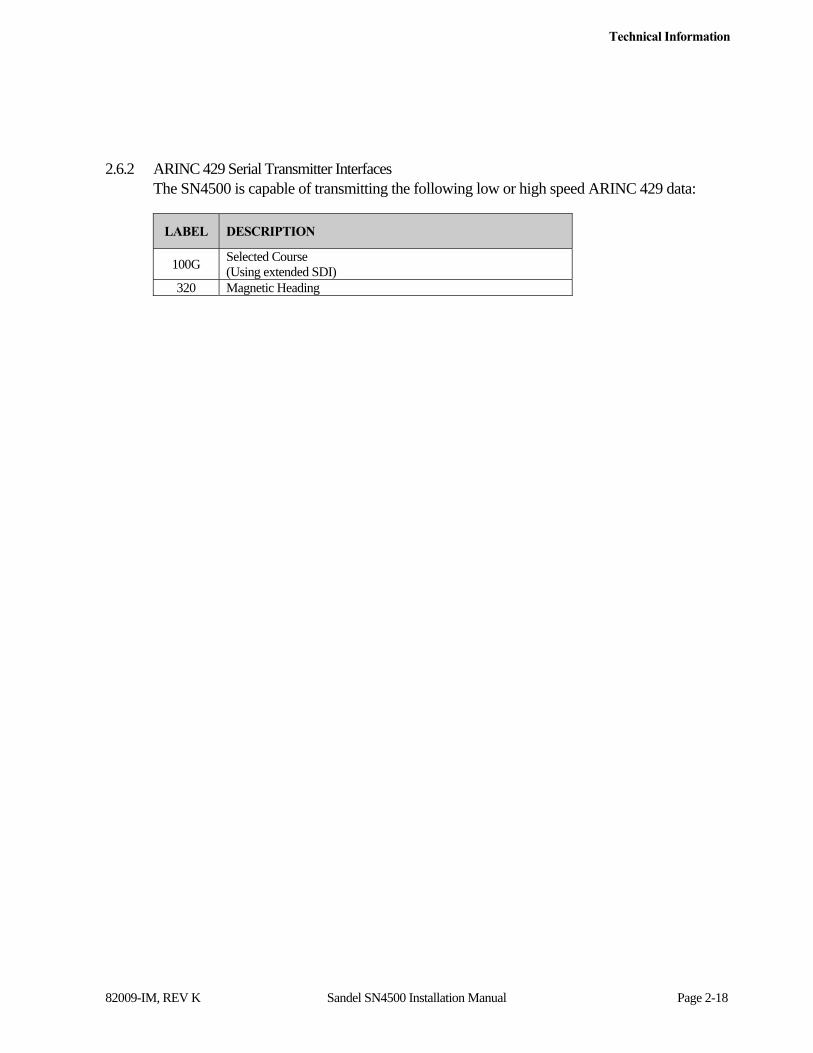
2.6.2 ARINC 429 Serial Transmitter Interfaces The SN4500 is capable of transmitting the following low or high speed ARINC 429 data:
LABEL DESCRIPTION
100G Selected Course (Using extended SDI)
320 Magnetic Heading

Installation
82009-IM, REV K Sandel SN4500 Installation Manual Page 3-1
3 Installation
3.1 General
This section provides general suggestions and information to consider before installing the SN4500 including interconnect diagrams, mounting dimensions and information pertaining to installation. Close adherence to these suggestions will assure optimum performance.
3.1.1 Unpacking and Inspecting Equipment Exercise extreme care when unpacking the equipment. Make a visual inspection of the unit for evidence of damage incurred during shipment. If a claim for damage is to be made, save the shipping container to substantiate the claim. The claim should be promptly filed with the carrier. It would be advisable to retain the container and packaging material after all equipment has been removed in the event that equipment storage or reshipment should become necessary.
3.2 Installation Considerations
3.2.1 General Considerations The SN4500 should be installed in accordance with standards established by the customer’s installing agency, and existing conditions as to unit location and type of installation. However, the following considerations should be heeded before installing the SN4500. Close adherence to these considerations will assure a more satisfactory performance from the equipment. The installing agency will supply and fabricate all external cables. The required connectors and associated hardware are supplied by Sandel Avionics.
3.2.2 Cooling Considerations The SN4500 contains its own ventilation fan for internal component cooling and therefore, does not require a forced air cooling system. Any questions concerning cooling can be verified in the post-installation checkout by monitoring the SN4500 Internal temperature on the System maintenance page.
3.2.3 Mechanical Installation Considerations The SN4500 installation should conform to customer requirements and airworthiness standards affecting the location and type of installation. §25.1321(a) stipulates that: “Each flight, navigation, and power plant instrument for use by any pilot must be plainly visible to him from his station with the minimum practicable deviation from his normal position and line of vision when he is looking forward along the flight path.”
§ 25.1321(b) stipulates: “The flight instruments required by §25.1303 must be grouped on the instrument panel and centered as nearly as practicable about the vertical plane of the pilot’s forward vision.” In addition - §25.1321(b)(4) states: “The instrument that most effectively indicates direction of flight must be adjacent to and directly below the instrument in the top center position.” Similar regulations apply to FAR Part 29 Transport Category Rotorcraft and to Part 23 Small Airplanes.
Refer to Sandel Avionics, Drawing No. 82009 titled, “Layout – SN4500 Installation” for specific assembly and mounting instructions.

Installation
82009-IM, REV K Sandel SN4500 Installation Manual Page 3-2
3.2.4 Electrical Installation Considerations Connections and functions of the SN4500 are described in this section. Refer to the SN4500 Interconnect Wiring Diagrams for detailed wiring information and appropriate notes. Refer to the Functional Pinout Descriptions for explanations of pin functions.
A. The installing agency will supply and fabricate all wiring harnesses. The length and routing of wires must be carefully measured and planned before the actual installation is attempted. Avoid sharp bends in the harness or locating the harness near aircraft controls. Observe all recommended wire sizes and types and subscribe to appropriate FAR Parts 23, 25, 27, and 29, as well as AC 43.13-1( ) and -2( ).
B. The use of MIL-C-27500 shielded wire and MIL-W-22759 single conductor wire is recommended. The use of ferrules or grounding blocks for signal ground and digital ground returns is satisfactory, however, each ground return must be electrically separated.
C. When an existing installation of a navigation source selection relay unit is installed to provide mode control switching and annunciation for a GPS or other long-range navigation system, the SN4500 may not perform these functions simultaneously. This does not preclude the SN4500 from annunciating such mode control functions.
D. In order to ensure optimum performance the SN4500 and associated wiring must be kept at least a minimum of three feet from high noise sources and not routed with cables from high power sources.
E. Prior to installing the SN4500, a point-to-point continuity check of the wiring harness should be accomplished to verify proper wiring. See FUNCTIONAL GROUND TEST PROCEDURES/REPORT in the appendix for verification of this step and other checks.
F. The Functional Pinout Descriptions on the following pages will assist you in determining installation requirements. Adhere to all notes within these descriptions and on installation wiring diagrams.
G. Special caution must be taken to observe 30 Hz OBS resolver connections in order to prevent possible damage to the installed VOR/localizer converter. See Installation Wiring Diagrams and the MAINTENANCE MENU, Configuration Instructions for notes pertaining to these considerations.
H. Ground Bonding. In order to assure installation characteristics match the DO-160 RF and Lightning test conditions, ensure that two ground wires of at least the recommended size are installed in accordance with the installation drawings and these wires are connected to a bonded aircraft ground. Ensure that shielded wiring is used to the Flux Gate (if installed), Gyro Reference, and Gyro XYZ (if installed).
I. Power Wiring. To assure that the SN4500 will operate properly down to its rated minimum input voltage of 22Vdc, ensure that two power wires of at least the

Installation
82009-IM, REV K Sandel SN4500 Installation Manual Page 3-3
recommended size are connected from the EHSI circuit breaker to the SN4500 in accordance with the installation drawings.
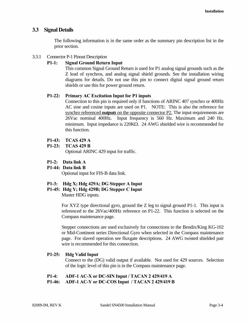
Installation
82009-IM, REV K Sandel SN4500 Installation Manual Page 3-4
3.3 Signal Details
The following information is in the same order as the summary pin description list in the prior section.
3.3.1 Connector P-1 Pinout Description P1-1: Signal Ground Return Input
This common Signal Ground Return is used for P1 analog signal grounds such as the Z lead of synchros, and analog signal shield grounds. See the installation wiring diagrams for details. Do not use this pin to connect digital signal ground return shields or use this for power ground return.
P1-22: Primary AC Excitation Input for P1 inputs Connection to this pin is required only if functions of ARINC 407 synchro or 400Hz AC sine and cosine inputs are used on P1. NOTE: This is also the reference for synchro referenced outputs on the opposite connector P2. The input requirements are 26Vac nominal 400Hz. Input frequency is 560 Hz. Maximum and 240 Hz. minimum. Input impedance is 220K. 24 AWG shielded wire is recommended for this function.
P1-43: TCAS 429 A P1-23: TCAS 429 B
Optional ARINC 429 input for traffic.
P1-2: Data link A P1-44: Data link B
Optional input for FIS-B data link.
P1-3: Hdg X; Hdg 429A; DG Stepper A Input P1-45: Hdg Y; Hdg 429B; DG Stepper C Input
Master HDG inputs.
For XYZ type directional gyro, ground the Z leg to signal ground P1-1. This input is referenced to the 26Vac/400Hz reference on P1-22. This function is selected on the Compass maintenance page.
Stepper connections are used exclusively for connections to the Bendix/King KG-102 or Mid-Continent series Directional Gyro when selected in the Compass maintenance page. For slaved operation see fluxgate descriptions. 24 AWG twisted shielded pair wire is recommended for this connection.
P1-25: Hdg Valid Input Connect to the (DG) valid output if available. Not used for 429 sources. Selection of the logic level of this pin is in the Compass maintenance page.
P1-4: ADF-1 AC-X or DC-SIN Input / TACAN 2 429/419 A P1-46: ADF-1 AC-Y or DC-COS Input / TACAN 2 429/419 B
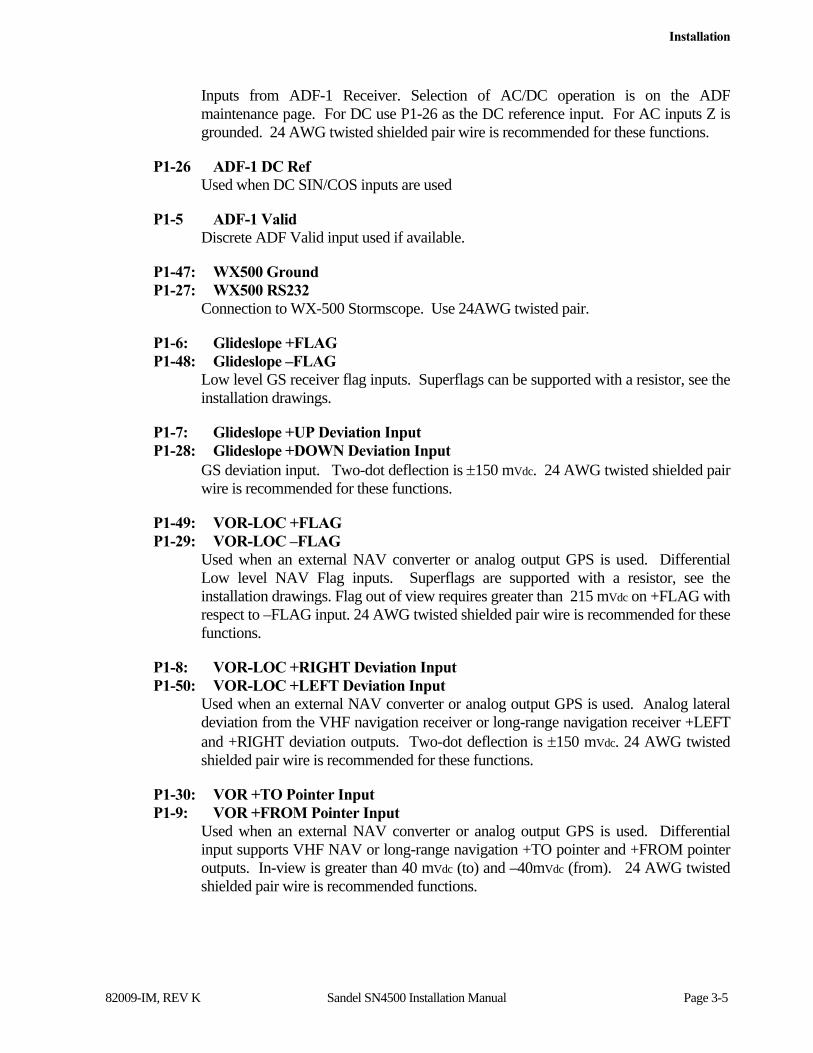
Installation
82009-IM, REV K Sandel SN4500 Installation Manual Page 3-5
Inputs from ADF-1 Receiver. Selection of AC/DC operation is on the ADF maintenance page. For DC use P1-26 as the DC reference input. For AC inputs Z is grounded. 24 AWG twisted shielded pair wire is recommended for these functions.
P1-26 ADF-1 DC Ref Used when DC SIN/COS inputs are used
P1-5 ADF-1 Valid Discrete ADF Valid input used if available.
P1-47: WX500 Ground P1-27: WX500 RS232
Connection to WX-500 Stormscope. Use 24AWG twisted pair.
P1-6: Glideslope +FLAG P1-48: Glideslope –FLAG
Low level GS receiver flag inputs. Superflags can be supported with a resistor, see the installation drawings.
P1-7: Glideslope +UP Deviation Input P1-28: Glideslope +DOWN Deviation Input
GS deviation input. Two-dot deflection is 150 mVdc. 24 AWG twisted shielded pair wire is recommended for these functions.
P1-49: VOR-LOC +FLAG P1-29: VOR-LOC –FLAG
Used when an external NAV converter or analog output GPS is used. Differential Low level NAV Flag inputs. Superflags are supported with a resistor, see the installation drawings. Flag out of view requires greater than 215 mVdc on +FLAG with respect to –FLAG input. 24 AWG twisted shielded pair wire is recommended for these functions.
P1-8: VOR-LOC +RIGHT Deviation Input P1-50: VOR-LOC +LEFT Deviation Input
Used when an external NAV converter or analog output GPS is used. Analog lateral deviation from the VHF navigation receiver or long-range navigation receiver +LEFT and +RIGHT deviation outputs. Two-dot deflection is 150 mVdc. 24 AWG twisted shielded pair wire is recommended for these functions.
P1-30: VOR +TO Pointer Input P1-9: VOR +FROM Pointer Input
Used when an external NAV converter or analog output GPS is used. Differential input supports VHF NAV or long-range navigation +TO pointer and +FROM pointer outputs. In-view is greater than 40 mVdc (to) and –40mVdc (from). 24 AWG twisted shielded pair wire is recommended functions.
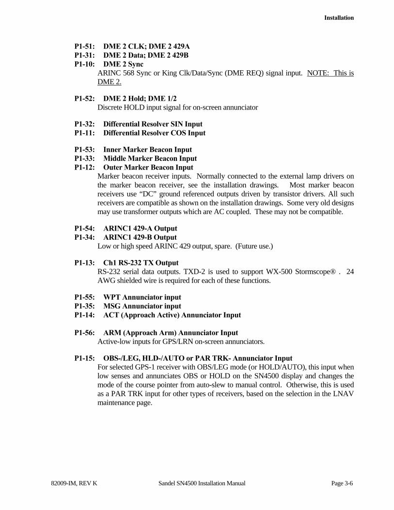
Installation
82009-IM, REV K Sandel SN4500 Installation Manual Page 3-6
P1-51: DME 2 CLK; DME 2 429A P1-31: DME 2 Data; DME 2 429B P1-10: DME 2 Sync
ARINC 568 Sync or King Clk/Data/Sync (DME REQ) signal input. NOTE: This is DME 2.
P1-52: DME 2 Hold; DME 1/2 Discrete HOLD input signal for on-screen annunciator
P1-32: Differential Resolver SIN Input P1-11: Differential Resolver COS Input
P1-53: Inner Marker Beacon Input P1-33: Middle Marker Beacon Input P1-12: Outer Marker Beacon Input
Marker beacon receiver inputs. Normally connected to the external lamp drivers on the marker beacon receiver, see the installation drawings. Most marker beacon receivers use “DC” ground referenced outputs driven by transistor drivers. All such receivers are compatible as shown on the installation drawings. Some very old designs may use transformer outputs which are AC coupled. These may not be compatible.
P1-54: ARINC1 429-A Output P1-34: ARINC1 429-B Output
Low or high speed ARINC 429 output, spare. (Future use.)
P1-13: Ch1 RS-232 TX Output RS-232 serial data outputs. TXD-2 is used to support WX-500 Stormscope® . 24 AWG shielded wire is required for each of these functions.
P1-55: WPT Annunciator input P1-35: MSG Annunciator input P1-14: ACT (Approach Active) Annunciator Input P1-56: ARM (Approach Arm) Annunciator Input
Active-low inputs for GPS/LRN on-screen annunciators.
P1-15: OBS-/LEG, HLD-/AUTO or PAR TRK- Annunciator Input For selected GPS-1 receiver with OBS/LEG mode (or HOLD/AUTO), this input when low senses and annunciates OBS or HOLD on the SN4500 display and changes the mode of the course pointer from auto-slew to manual control. Otherwise, this is used as a PAR TRK input for other types of receivers, based on the selection in the LNAV maintenance page.

Installation
82009-IM, REV K Sandel SN4500 Installation Manual Page 3-7
P1-58: ILS Energize 1 Alternate P1-38: ILS Energize 2 Alternate P1-19: Remote Course Control X Input P1-61: Remote Course Control Y Input P1-20: Remote Heading Control X Input P1-62: Remote Heading Control Y Input P1-21: Remote Dimmer Control Input
3.3.2 Connector P-2 Pinout Descriptions P2-1: Signal Ground Return Input
This common Signal Ground Return is used for P2 analog signal grounds such as the Z lead of synchros, and analog signal shield grounds. See the installation wiring diagrams for details. Do not use this pin to connect digital signal ground return shields or use this for power ground return.
P2-16: AC Excitation Input for P2 inputs Connection to this pin is required only if functions of ARINC 407 synchro or 400Hz AC sine and cosine inputs on P2. It does NOT apply to outputs on P2. The input requirements are 26Vac nominal 400Hz. Input frequency is 560 Hz. Maximum and 240 Hz. minimum. Input impedance is 220K. 24 AWG shielded wire is recommended for this function.
P2-31: GPS1/FMS 1 429A/422+/232 Gnd P2-17: GPS1/FMS 1 429B/422-/232 Signal
Main input from GPS/FMS 1.
P2-2: GPS2/FMS 2 429A/422+/232 Gnd P2-32: GPS2/FMS 2 429B/422-/232 Signal
Main input from GPS/FMS 2.
P2-18: VHF Nav-1 ILS Energize Input or Heading Alternate X input This pin controls the Vertical Deviation Bar when selected to NAV1. These signals also control the ILS Lockout logic so the SN4500 can sense when a GPS receiver is inappropriately selected as the primary NAV source when ILS Lockout is not disabled on the NAV maintenance page. Connections to these pins are from the respective VHF navigation receiver and optionally by the GPS receiver. The logic level of these inputs is selected on the NAV maintenance page, and is normally active-low.
P2-3: VHF NAV1 429A/Composite P2-33: VHF NAV1 429B
Primary 429 input from VHF NAV1, or composite input from analog receiver for VOR bearing pointer. Composite is normally .5v VOR / .33v LOC. For 3V inputs a series resistor is required, see the installation drawings. When using the composite input for LOC deviation, the calibration procedure found in section 7.1.5 must be followed for each specific LOC input. 24 AWG shielded wire is recommended for these connections. Note: When using the composite signal for the localizer deviation
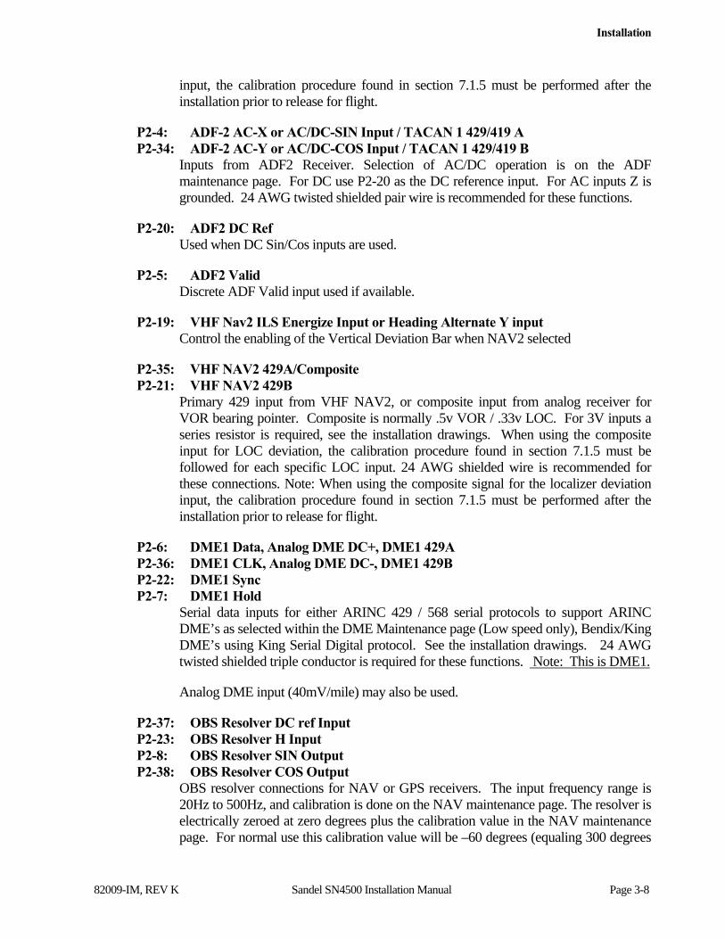
Installation
82009-IM, REV K Sandel SN4500 Installation Manual Page 3-8
input, the calibration procedure found in section 7.1.5 must be performed after the installation prior to release for flight.
P2-4: ADF-2 AC-X or AC/DC-SIN Input / TACAN 1 429/419 A P2-34: ADF-2 AC-Y or AC/DC-COS Input / TACAN 1 429/419 B
Inputs from ADF2 Receiver. Selection of AC/DC operation is on the ADF maintenance page. For DC use P2-20 as the DC reference input. For AC inputs Z is grounded. 24 AWG twisted shielded pair wire is recommended for these functions.
P2-20: ADF2 DC Ref Used when DC Sin/Cos inputs are used.
P2-5: ADF2 Valid Discrete ADF Valid input used if available.
P2-19: VHF Nav2 ILS Energize Input or Heading Alternate Y input Control the enabling of the Vertical Deviation Bar when NAV2 selected
P2-35: VHF NAV2 429A/Composite P2-21: VHF NAV2 429B
Primary 429 input from VHF NAV2, or composite input from analog receiver for VOR bearing pointer. Composite is normally .5v VOR / .33v LOC. For 3V inputs a series resistor is required, see the installation drawings. When using the composite input for LOC deviation, the calibration procedure found in section 7.1.5 must be followed for each specific LOC input. 24 AWG shielded wire is recommended for these connections. Note: When using the composite signal for the localizer deviation input, the calibration procedure found in section 7.1.5 must be performed after the installation prior to release for flight.
P2-6: DME1 Data, Analog DME DC+, DME1 429A P2-36: DME1 CLK, Analog DME DC-, DME1 429B P2-22: DME1 Sync P2-7: DME1 Hold
Serial data inputs for either ARINC 429 / 568 serial protocols to support ARINC DME’s as selected within the DME Maintenance page (Low speed only), Bendix/King DME’s using King Serial Digital protocol. See the installation drawings. 24 AWG twisted shielded triple conductor is required for these functions. Note: This is DME1.
Analog DME input (40mV/mile) may also be used.
P2-37: OBS Resolver DC ref Input P2-23: OBS Resolver H Input P2-8: OBS Resolver SIN Output P2-38: OBS Resolver COS Output
OBS resolver connections for NAV or GPS receivers. The input frequency range is 20Hz to 500Hz, and calibration is done on the NAV maintenance page. The resolver is electrically zeroed at zero degrees plus the calibration value in the NAV maintenance page. For normal use this calibration value will be –60 degrees (equaling 300 degrees
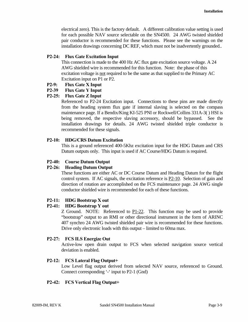
Installation
82009-IM, REV K Sandel SN4500 Installation Manual Page 3-9
electrical zero). This is the factory default. A different calibration value setting is used for each possible NAV source selectable on the SN4500. 24 AWG twisted shielded pair conductor is recommended for these functions. Please see the warnings on the installation drawings concerning DC REF, which must not be inadvertently grounded..
P2-24: Flux Gate Excitation Input This connection is made to the 400 Hz AC flux gate excitation source voltage. A 24 AWG shielded wire is recommended for this function. Note: the phase of this excitation voltage is not required to be the same as that supplied to the Primary AC Excitation input on P1 or P2.
P2-9: Flux Gate X Input P2-39 Flux Gate Y Input P2-25: Flux Gate Z Input
Referenced to P2-24 Excitation input. Connections to these pins are made directly from the heading system flux gate if internal slaving is selected on the compass maintenance page. If a Bendix/King KI-525 PNI or Rockwell/Collins 331A-3( ) HSI is being removed, the respective slaving accessory, should be bypassed. See the installation drawings for details. 24 AWG twisted shielded triple conductor is recommended for these signals.
P2-10: HDG/CRS Datum Excitation This is a ground referenced 400-5Khz excitation input for the HDG Datum and CRS Datum outputs only. This input is used if AC Course/HDG Datum is required.
P2-40: Course Datum Output P2-26: Heading Datum Output
These functions are either AC or DC Course Datum and Heading Datum for the flight control system. If AC signals, the excitation reference is P2-10. Selection of gain and direction of rotation are accomplished on the FCS maintenance page. 24 AWG single conductor shielded wire is recommended for each of these functions.
P2-11: HDG Bootstrap X out P2-41: HDG Bootstrap Y out
Z Ground. NOTE: Referenced to P1-22. This function may be used to provide “bootstrap” output to an RMI or other directional instrument in the form of ARINC 407 synchro 24 AWG twisted shielded pair wire is recommended for these functions. Drive only electronic loads with this output – limited to 60ma max.
P2-27: FCS ILS Energize Out Active-low open drain output to FCS when selected navigation source vertical deviation is enabled.
P2-12: FCS Lateral Flag Output+ Low Level flag output derived from selected NAV source, referenced to Ground. Connect corresponding ‘-‘ input to P2-1 (Gnd)
P2-42: FCS Vertical Flag Output+

Installation
82009-IM, REV K Sandel SN4500 Installation Manual Page 3-10
Low Level flag output derived from selected NAV source, referenced to Ground. Connect corresponding ‘-‘ input to P2-1 (Gnd)
P2-28: FCS Lateral Deviation Output +Right LL lateral +deviation from selected NAV source. Connect corresponding ‘-‘ deviation input to P2-1 (Gnd)
P2-13: FCS Vertical Deviation Output + LL vertical +deviation from selected NAV source. Connect corresponding ‘-‘ deviation input to P2-1 (Gnd)
P2-43: FCS Lateral Superflag Output Superflag output derived from selected NAV source.
P2-29: FCS Vertical Superflag Output Superflag output derived from selected NAV source.
P2-14: RS-232 TX Output2 RS-232 serial FIS-B data link output (Software Rev 3.0 and above).
P2-30: ARINC2 429-A Output P2-15: ARINC2 429-B Output
Low or high speed ARINC 429 output which transmits selected course and selected heading for ARINC 429 Long Range NAV receivers. 24 AWG twisted shielded pair wire is required for these functions.
3.3.3 Connector P-3 Pinout Descriptions
P3-1 & P3-9: Display Primary Power Input
(22-33Vdc) Connection to both pins is required using two 20AWG wires and a 5 ampere circuit breaker. Nominal power required is 40 watts. Connection to the avionics bus is recommended to reduce voltage fluctuations during engine start.
P3-3 & P3-11: Display Power Return Input
Pins 3 and 11 are the aircraft ground input connections. Connection to both pins is required using two 20 AWG wires. Either pin should also be used for the digital signal ground (shields) return, as required. The number of shields will vary depending upon the functions wired to Connector P3.
P3-2: GPS OBS- or HOLD- Command Discrete Output or TACAN Relay Out
Open Drain active-low output used to operate the OBS function of Bendix/King KLN-90 GPS receivers or the HOLD function of the II Morrow and Garmin GPS receivers. Accessible during normal use from the pilots GPS MODE soft key. Can also be used to operate a switching relay, or external annunciator whenever a TACAN is selected
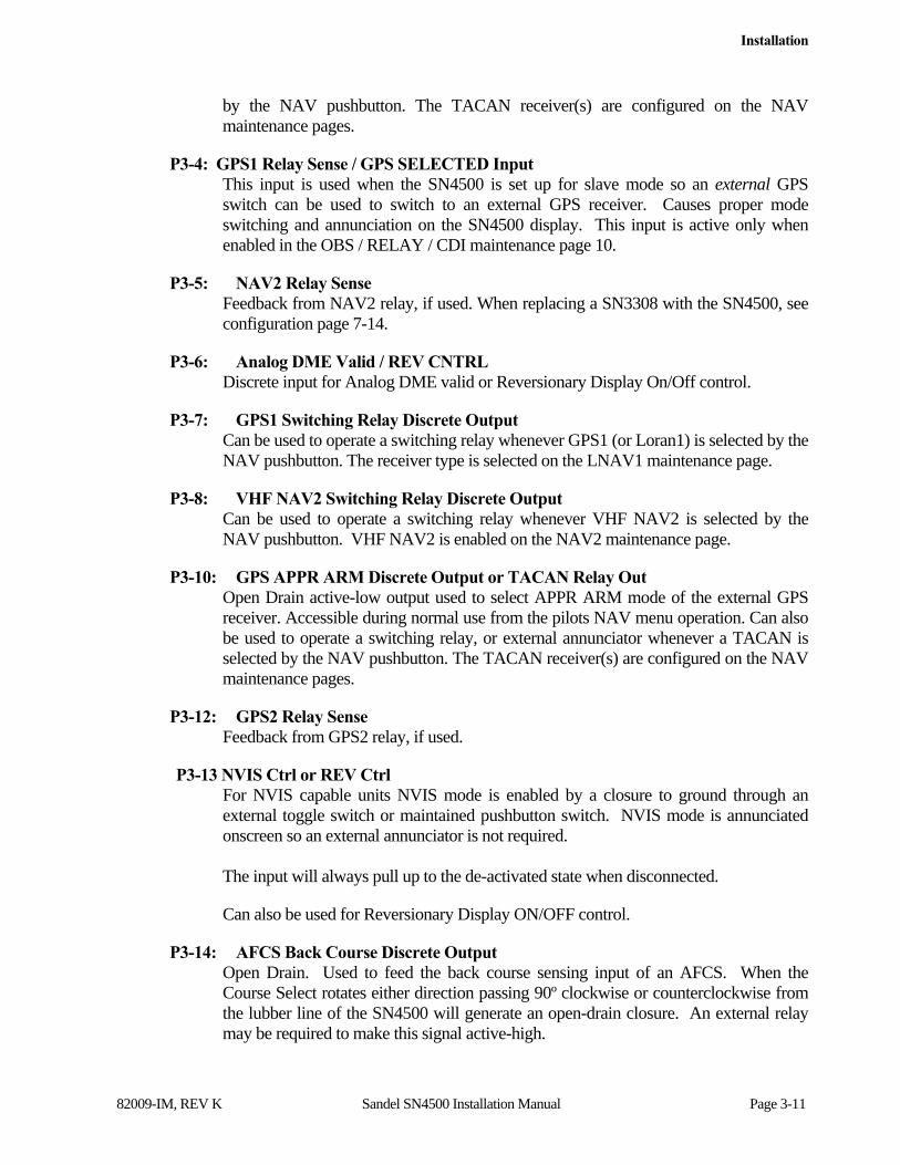
Installation
82009-IM, REV K Sandel SN4500 Installation Manual Page 3-11
by the NAV pushbutton. The TACAN receiver(s) are configured on the NAV maintenance pages.
P3-4: GPS1 Relay Sense / GPS SELECTED Input This input is used when the SN4500 is set up for slave mode so an external GPS switch can be used to switch to an external GPS receiver. Causes proper mode switching and annunciation on the SN4500 display. This input is active only when enabled in the OBS / RELAY / CDI maintenance page 10.
P3-5: NAV2 Relay Sense Feedback from NAV2 relay, if used. When replacing a SN3308 with the SN4500, see configuration page 7-14.
P3-6: Analog DME Valid / REV CNTRL Discrete input for Analog DME valid or Reversionary Display On/Off control.
P3-7: GPS1 Switching Relay Discrete Output Can be used to operate a switching relay whenever GPS1 (or Loran1) is selected by the NAV pushbutton. The receiver type is selected on the LNAV1 maintenance page.
P3-8: VHF NAV2 Switching Relay Discrete Output Can be used to operate a switching relay whenever VHF NAV2 is selected by the NAV pushbutton. VHF NAV2 is enabled on the NAV2 maintenance page.
P3-10: GPS APPR ARM Discrete Output or TACAN Relay Out Open Drain active-low output used to select APPR ARM mode of the external GPS receiver. Accessible during normal use from the pilots NAV menu operation. Can also be used to operate a switching relay, or external annunciator whenever a TACAN is selected by the NAV pushbutton. The TACAN receiver(s) are configured on the NAV maintenance pages.
P3-12: GPS2 Relay Sense Feedback from GPS2 relay, if used.
P3-13 NVIS Ctrl or REV Ctrl For NVIS capable units NVIS mode is enabled by a closure to ground through an external toggle switch or maintained pushbutton switch. NVIS mode is annunciated onscreen so an external annunciator is not required. The input will always pull up to the de-activated state when disconnected.
Can also be used for Reversionary Display ON/OFF control.
P3-14: AFCS Back Course Discrete Output Open Drain. Used to feed the back course sensing input of an AFCS. When the Course Select rotates either direction passing 90º clockwise or counterclockwise from the lubber line of the SN4500 will generate an open-drain closure. An external relay may be required to make this signal active-high.

Installation
82009-IM, REV K Sandel SN4500 Installation Manual Page 3-12
P3-15: GPS2 Switching Relay Discrete Output Can be used to operate a switching relay whenever GPS2 (or Loran2) is selected by the NAV pushbutton. The receiver type is selected on the LNAV-2 maintenance page.
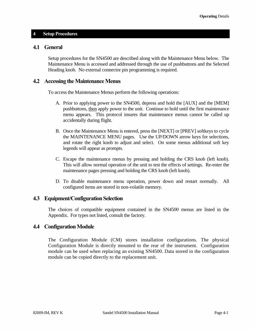
Operating Details
82009-IM, REV K Sandel SN4500 Installation Manual Page 4-1
4 Setup Procedures
4.1 General
Setup procedures for the SN4500 are described along with the Maintenance Menu below. The Maintenance Menu is accessed and addressed through the use of pushbuttons and the Selected Heading knob. No external connector pin programming is required.
4.2 Accessing the Maintenance Menus
To access the Maintenance Menus perform the following operations:
A. Prior to applying power to the SN4500, depress and hold the [AUX] and the [MEM] pushbuttons, then apply power to the unit. Continue to hold until the first maintenance menu appears. This protocol insures that maintenance menus cannot be called up accidentally during flight.
B. Once the Maintenance Menu is entered, press the [NEXT] or [PREV] softkeys to cycle the MAINTENANCE MENU pages. Use the UP/DOWN arrow keys for selections, and rotate the right knob to adjust and select. On some menus additional soft key legends will appear as prompts.
C. Escape the maintenance menus by pressing and holding the CRS knob (left knob). This will allow normal operation of the unit to test the effects of settings. Re-enter the maintenance pages pressing and holding the CRS knob (left knob).
D. To disable maintenance menu operation, power down and restart normally. All configured items are stored in non-volatile memory.
4.3 Equipment/Configuration Selection
The choices of compatible equipment contained in the SN4500 menus are listed in the Appendix. For types not listed, consult the factory.
4.4 Configuration Module
The Configuration Module (CM) stores installation configurations. The physical Configuration Module is directly mounted to the rear of the instrument. Configuration module can be used when replacing an existing SN4500. Data stored in the configuration module can be copied directly to the replacement unit.
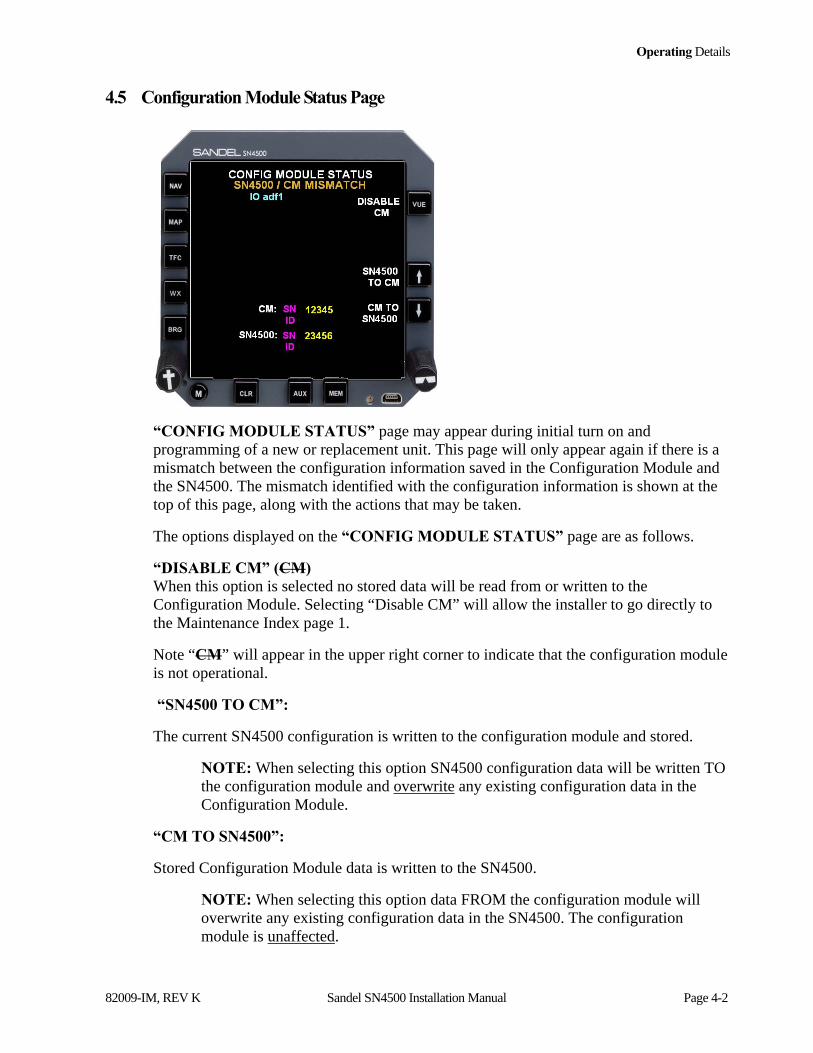
Operating Details
82009-IM, REV K Sandel SN4500 Installation Manual Page 4-2
4.5 Configuration Module Status Page
“CONFIG MODULE STATUS” page may appear during initial turn on and programming of a new or replacement unit. This page will only appear again if there is a mismatch between the configuration information saved in the Configuration Module and the SN4500. The mismatch identified with the configuration information is shown at the top of this page, along with the actions that may be taken.
The options displayed on the “CONFIG MODULE STATUS” page are as follows.
“DISABLE CM” (CM) When this option is selected no stored data will be read from or written to the Configuration Module. Selecting “Disable CM” will allow the installer to go directly to the Maintenance Index page 1.
Note “CM” will appear in the upper right corner to indicate that the configuration module is not operational.
“SN4500 TO CM”:
The current SN4500 configuration is written to the configuration module and stored.
NOTE: When selecting this option SN4500 configuration data will be written TO the configuration module and overwrite any existing configuration data in the Configuration Module.
“CM TO SN4500”:
Stored Configuration Module data is written to the SN4500.
NOTE: When selecting this option data FROM the configuration module will overwrite any existing configuration data in the SN4500. The configuration module is unaffected.
Operating Details
82009-IM, REV K Sandel SN4500 Installation Manual Page 4-3
As part of the configuration, an aircraft identifier (Tail Number) should be entered on the systems settings page.
If installing a replacement SN4500 (using the existing Configuration Module):
To clear the SN4500 / CM MISMATCH message, perform the following steps in this order:
1) Select CM to SN4500 to write stored Configuration Module data to the SN4500.
2) Select SN4500 to CM.

Operating Details
82009-IM, REV K Sandel SN4500 Installation Manual Page 5-1
5 Operating Details
For an explanation of the operating controls of the SN4500, refer to the Pilot’s Guide for the SN4500, Sandel Avionics P/N 82009-PG, and to the Airplane Flight Manual Supplement.

Instructions For Continued Airworthiness
82009-IM, REV K Sandel SN4500 Installation Manual Page 6-1
6 Instructions For Continued Airworthiness
The following is a summary of the Instructions for Continued Airworthiness prepared under the guidelines of FAA Advisory Circulars 23.1309-1( ) and 25.1309-1( ) which identifies potential failure modes of the Sandel Avionics Model SN4500 Navigation Display. The assumption made is that all functions of the SN4500 will be used in an essential (primary) navigation function.
No scheduled maintenance required.

Appendix A: Post-Installation Procedures
82009-IM, REV K Sandel SN4500 Installation Manual Page 7-1
7 Appendix A: Post-Installation Procedures
After all wiring has been verified and the SN4500 has been installed into the panel, the maintenance pages must be accessed to properly configure the SN4500 for the installed equipment. Prior to applying power to the SN4500, depress and hold the [AUX] and the [MEM] keys, and then apply power to the unit. Continue to hold until the first maintenance menu appears. This protocol insures than maintenance menus cannot be called up accidentally during flight.
Once the Maintenance Menu is entered, press the [NEXT] or [PREV] softkeys to cycle the MAINTENANCE MENU pages. Use the UP/DOWN arrow keys for selections, and rotate the right knob to adjust and select. On some menus additional soft key legends will appear as prompts.
Escape the maintenance menus by pressing and holding the CRS knob. This will allow normal operation of the unit to test the effects of settings. Re-enter the maintenance pages pressing and holding the CRS knob.
To disable maintenance menu operation, power down and restart normally. All configured items will be stored in non-volatile memory.
NOTE: When configuring ARINC 429 inputs, select ‘429’ for low-speed and ‘429H’ for high-speed.
Each maintenance page, the options for each, and a brief description of each option are detailed below:
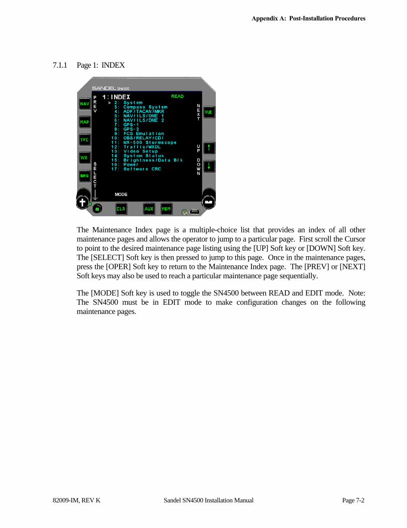
Appendix A: Post-Installation Procedures
82009-IM, REV K Sandel SN4500 Installation Manual Page 7-2
7.1.1 Page 1: INDEX
The Maintenance Index page is a multiple-choice list that provides an index of all other maintenance pages and allows the operator to jump to a particular page. First scroll the Cursor to point to the desired maintenance page listing using the [UP] Soft key or [DOWN] Soft key. The [SELECT] Soft key is then pressed to jump to this page. Once in the maintenance pages, press the [OPER] Soft key to return to the Maintenance Index page. The [PREV] or [NEXT] Soft keys may also be used to reach a particular maintenance page sequentially.
The [MODE] Soft key is used to toggle the SN4500 between READ and EDIT mode. Note: The SN4500 must be in EDIT mode to make configuration changes on the following maintenance pages.

Appendix A: Post-Installation Procedures
82009-IM, REV K Sandel SN4500 Installation Manual Page 7-3
7.1.2 Page 2: SYSTEM
The System page provides information that identifies the unit and the unit’s hardware and software.
Configuration Field Options Comment
Rmt Switch Annun NO YES
Set to yes to allow SN4500 to control GPS switch inputs (LEG/OBS switching, APPR ARM etc.) through Pilot’s Menu. Available options will depend on the model of GPS selected on the GPS maintenance page.
TCN Discr Out None P3-2 P3-10
Selects which pin connector pin is assigned to TACAN Relay Out Signal.
Install Position PLT ONLY PLT DUAL COP DUAL
Set to adjust color of on-side/cross-side NAV information.
Hdg Bug Color ORANGE WHITE
Selects desired heading bug color.
Loc/GS pointer BAR TRIANGLE
Selects style of Loc/GS pointer.
Center VDI Ena ENABLE DISABLE
Set to enable or disable display of the inner Vertical Deviation Indicator.
Aircraft Ident 7 characters Enter aircraft identification for reference.

Appendix A: Post-Installation Procedures
82009-IM, REV K Sandel SN4500 Installation Manual Page 7-4
Configuration Field Options Comment
Data recording ENABLE DISABLE
Set ENABLE to allow data recording.

Appendix A: Post-Installation Procedures
82009-IM, REV K Sandel SN4500 Installation Manual Page 7-5
7.1.3 Page 3: COMPASS SYSTEM
The Compass System page configures the gyro and fluxgate (if applicable) to the SN4500.
Configuration Field Options Comment
HEADING NONE 429 429H XYZ XYZ- MID CONT KG102 XYZ INV 2 XYZ- INV 2
Selects the gyro input to the SN4500. Alternate inverter selection Alternate inverter selection
ATT Key xxxxxxxxxxx 11 – char activation key for Reversionary Attitude Feature
ATT Pin NONE ACTIVE L (P3-06) ACTIVE L (P3-13)
Enables the pin used for Reversionary Attitude discrete input. Select ACTIVE L such that either P3-06 or P3-13 is displayed in the PINS field.
PTCH CAL d.dd Pitch Adjustment of Reversionary Attitude display +/- 5.00
VALID NONE HIGH LOW
Not shown if 429 or 429H is selected for heading.
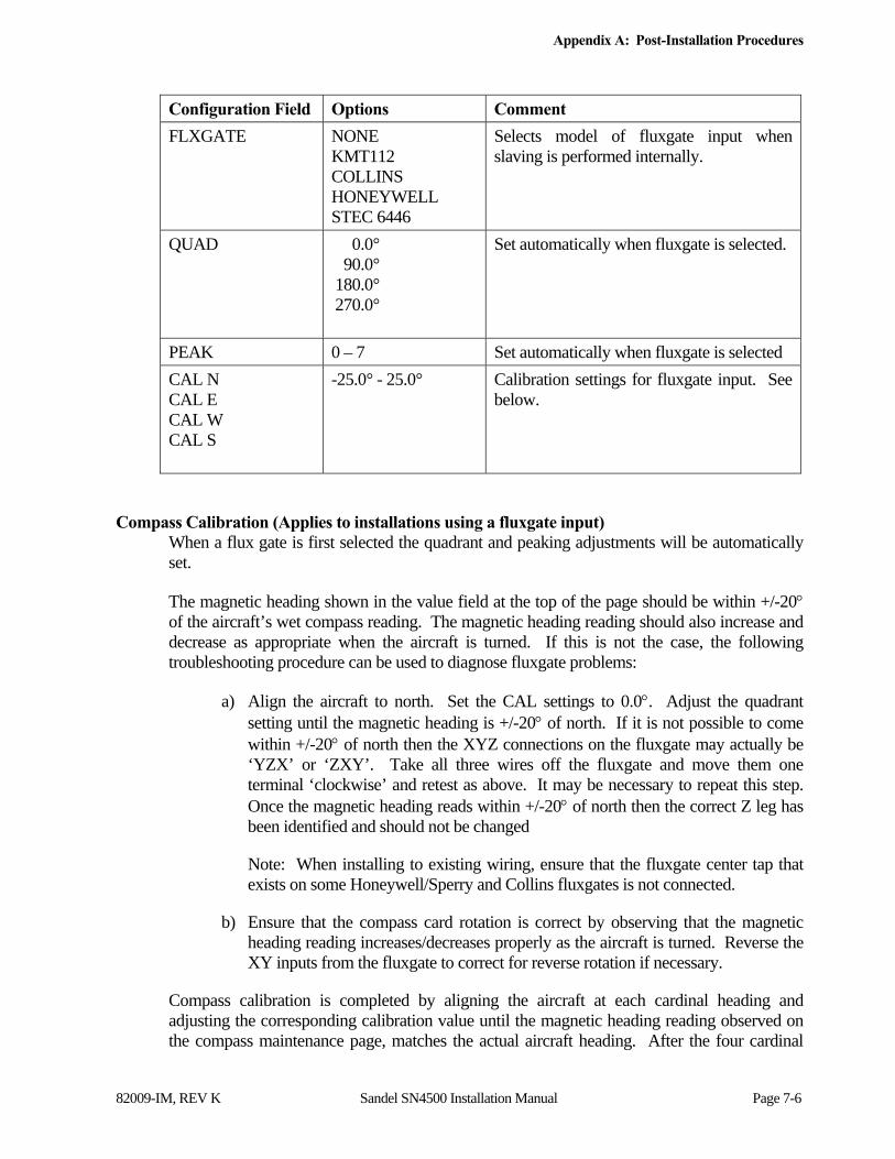
Appendix A: Post-Installation Procedures
82009-IM, REV K Sandel SN4500 Installation Manual Page 7-6
Configuration Field Options Comment
FLXGATE NONE KMT112 COLLINS HONEYWELL STEC 6446
Selects model of fluxgate input when slaving is performed internally.
QUAD 0.0° 90.0° 180.0° 270.0°
Set automatically when fluxgate is selected.
PEAK 0 – 7 Set automatically when fluxgate is selected
CAL N CAL E CAL W CAL S
-25.0° - 25.0° Calibration settings for fluxgate input. See below.
Compass Calibration (Applies to installations using a fluxgate input) When a flux gate is first selected the quadrant and peaking adjustments will be automatically set.
The magnetic heading shown in the value field at the top of the page should be within +/-20 of the aircraft’s wet compass reading. The magnetic heading reading should also increase and decrease as appropriate when the aircraft is turned. If this is not the case, the following troubleshooting procedure can be used to diagnose fluxgate problems:
a) Align the aircraft to north. Set the CAL settings to 0.0. Adjust the quadrant setting until the magnetic heading is +/-20 of north. If it is not possible to come within +/-20 of north then the XYZ connections on the fluxgate may actually be ‘YZX’ or ‘ZXY’. Take all three wires off the fluxgate and move them one terminal ‘clockwise’ and retest as above. It may be necessary to repeat this step. Once the magnetic heading reads within +/-20 of north then the correct Z leg has been identified and should not be changed
Note: When installing to existing wiring, ensure that the fluxgate center tap that exists on some Honeywell/Sperry and Collins fluxgates is not connected.
b) Ensure that the compass card rotation is correct by observing that the magnetic heading reading increases/decreases properly as the aircraft is turned. Reverse the XY inputs from the fluxgate to correct for reverse rotation if necessary.
Compass calibration is completed by aligning the aircraft at each cardinal heading and adjusting the corresponding calibration value until the magnetic heading reading observed on the compass maintenance page, matches the actual aircraft heading. After the four cardinal

Appendix A: Post-Installation Procedures
82009-IM, REV K Sandel SN4500 Installation Manual Page 7-7
points have been adjusted and verified, a final check of the systems should be done by power cycling the SN4500 into normal mode and ensuring the compass rose is correct for each cardinal heading.
NOTE: Changes to the compass calibration settings may take up to two minutes to take effect when observing the compass card in normal operational mode. Therefore It is recommended to make these calibration adjustments on the compass maintenance page where the compass readings are instantaneous and not affected by the slaving logic in the SN4500.
Reversionary Attitude Configuration (ARINC 429 Low/High speed only) When the HEADING source is configured as ARINC 429, an optional Reversionary Attitude Mode is available for activation via a valid key entry. Once configured and valid, P3-pin 6 or pin 13 input discrete connected to an external switch controls the switching between HSI Mode and Reversionary Attitude Mode.
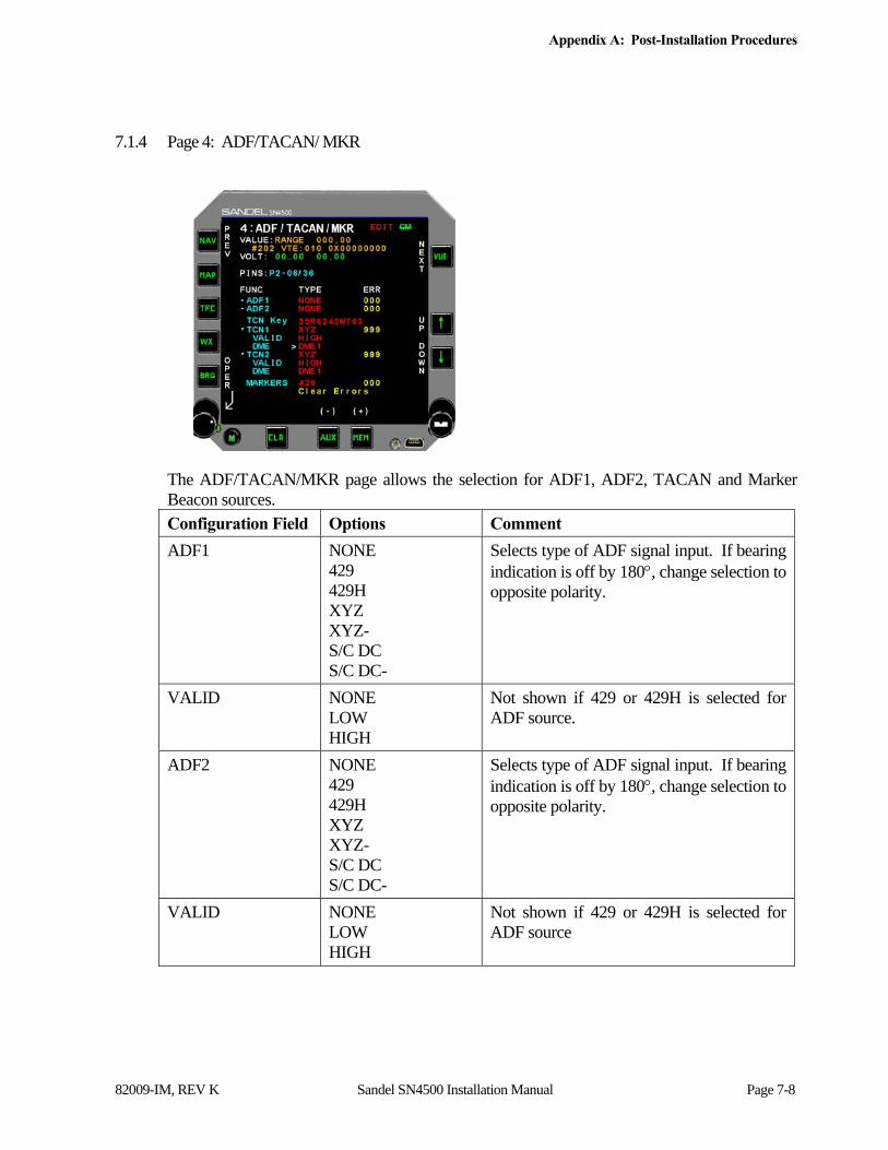
Appendix A: Post-Installation Procedures
82009-IM, REV K Sandel SN4500 Installation Manual Page 7-8
7.1.4 Page 4: ADF/TACAN/ MKR
The ADF/TACAN/MKR page allows the selection for ADF1, ADF2, TACAN and Marker Beacon sources. Configuration Field Options Comment
ADF1 NONE 429 429H XYZ XYZ- S/C DC S/C DC-
Selects type of ADF signal input. If bearing indication is off by 180, change selection to opposite polarity.
VALID NONE LOW HIGH
Not shown if 429 or 429H is selected for ADF source.
ADF2 NONE 429 429H XYZ XYZ- S/C DC S/C DC-
Selects type of ADF signal input. If bearing indication is off by 180, change selection to opposite polarity.
VALID NONE LOW HIGH
Not shown if 429 or 429H is selected for ADF source

Appendix A: Post-Installation Procedures
82009-IM, REV K Sandel SN4500 Installation Manual Page 7-9
Configuration Field Options Comment
TCN Key Blank by default Enter the purchased 11 character key code to enable TACAN. Use the AUX and MEM keys to select the character and the MAP and TFC keys to move the cursor.
TCN1 NONE 429 429H 429-MC 429H-MC XYZ XYZ- 419
Selects type of TACAN signal input. If bearing indication is off by 180, change selection to opposite polarity.
VALID NONE HIGH LOW
Shown only when TACAN selection is XYZ or XYZ-.
DME NONE DME 1 DME 2
Selects the source of DME data for the TACAN. Shown only when TACAN selection is XYZ or XYZ-.
TCN2 NONE 429 429H 429-MC 429H-MC XYZ XYZ- 419
Selects type of TACAN signal input. If bearing indication is off by 180, change selection to opposite polarity.
VALID NONE HIGH LOW
Shown only when TACAN selection is XYZ or XYZ-.
DME NONE DME 1 DME 2
Selects the source of DME data for the TACAN. Shown only when TACAN selection is XYZ or XYZ-.
MARKERS NONE ACTIVE L ACTIVE H 429 429H
Selects type of input from the marker beacon receiver.
THOLD Default 003 Used to adjust the signal voltage threshold when ACTIVE L or ACTIVE H is selected for the marker beacon input.
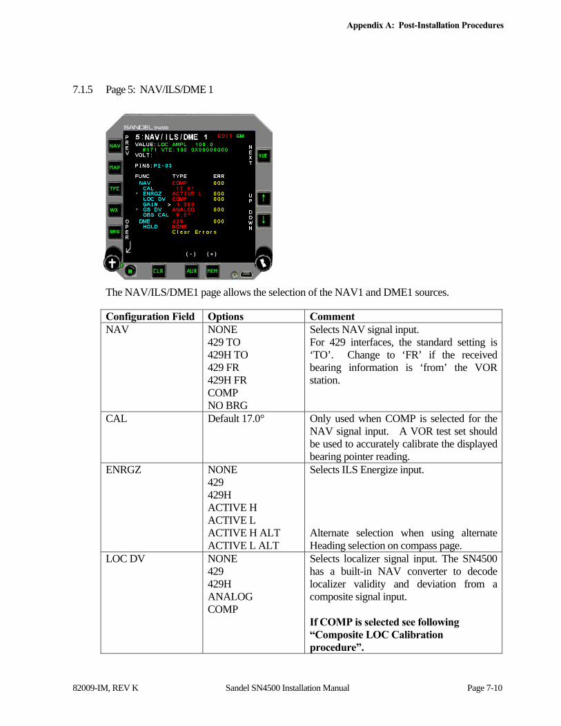
Appendix A: Post-Installation Procedures
82009-IM, REV K Sandel SN4500 Installation Manual Page 7-10
7.1.5 Page 5: NAV/ILS/DME 1
The NAV/ILS/DME1 page allows the selection of the NAV1 and DME1 sources.
Configuration Field Options Comment NAV NONE
429 TO 429H TO 429 FR 429H FR COMP NO BRG
Selects NAV signal input. For 429 interfaces, the standard setting is ‘TO’. Change to ‘FR’ if the received bearing information is ‘from’ the VOR station.
CAL Default 17.0° Only used when COMP is selected for the NAV signal input. A VOR test set should be used to accurately calibrate the displayed bearing pointer reading.
ENRGZ NONE 429 429H ACTIVE H ACTIVE L ACTIVE H ALT ACTIVE L ALT
Selects ILS Energize input. Alternate selection when using alternate Heading selection on compass page.
LOC DV NONE 429 429H ANALOG COMP
Selects localizer signal input. The SN4500 has a built-in NAV converter to decode localizer validity and deviation from a composite signal input. If COMP is selected see following “Composite LOC Calibration procedure”.
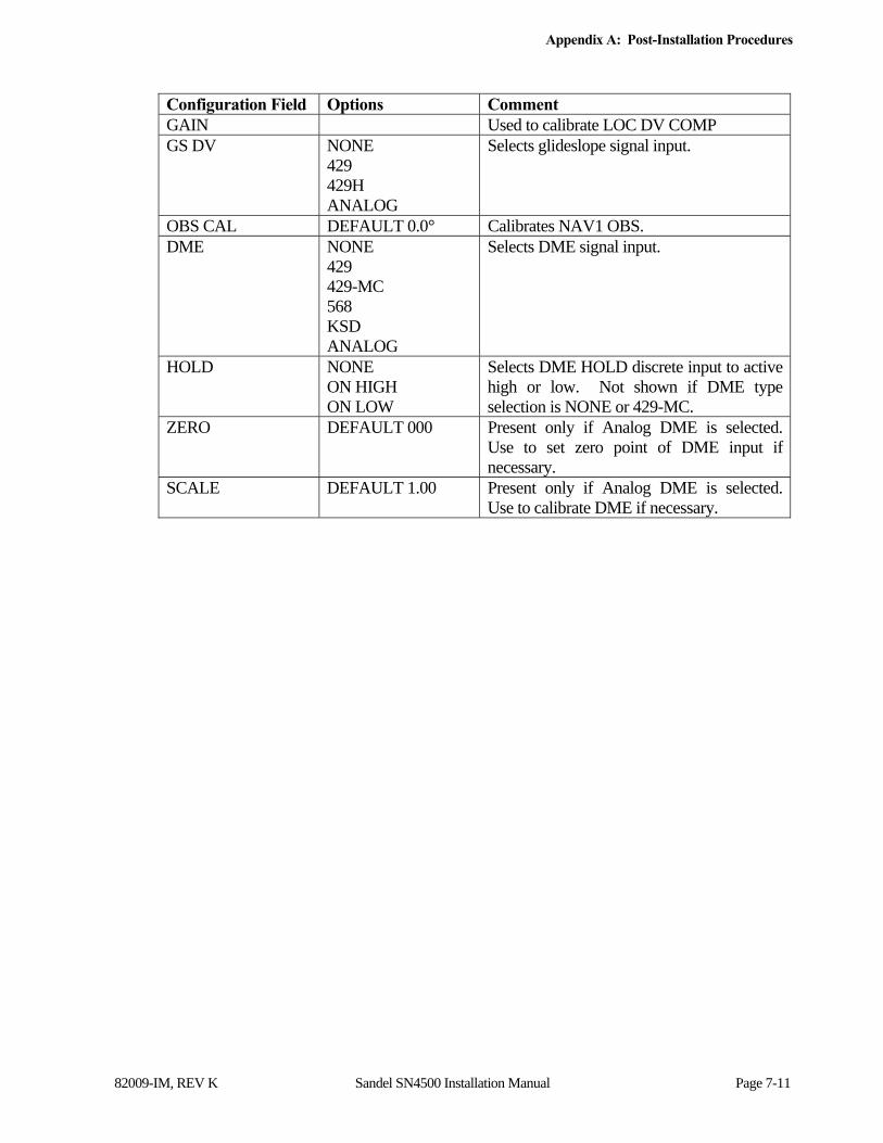
Appendix A: Post-Installation Procedures
82009-IM, REV K Sandel SN4500 Installation Manual Page 7-11
Configuration Field Options Comment GAIN Used to calibrate LOC DV COMP GS DV NONE
429 429H ANALOG
Selects glideslope signal input.
OBS CAL DEFAULT 0.0° Calibrates NAV1 OBS. DME NONE
429 429-MC 568 KSD ANALOG
Selects DME signal input.
HOLD NONE ON HIGH ON LOW
Selects DME HOLD discrete input to active high or low. Not shown if DME type selection is NONE or 429-MC.
ZERO DEFAULT 000 Present only if Analog DME is selected. Use to set zero point of DME input if necessary.
SCALE DEFAULT 1.00 Present only if Analog DME is selected. Use to calibrate DME if necessary.

Appendix A: Post-Installation Procedures
82009-IM, REV K Sandel SN4500 Installation Manual Page 7-12
OBS Calibration (Does not apply to 429 or 400HZ Differential Resolvers) Note: While in the maintenance mode pressing and holding the CRS knob will toggle the display between the operational display and maintenance setup pages.
a) In operational mode set the SN4500 course pointer (OBS) to zero degrees. Set the NAV test set to zero degrees.
b) In Maintenance Mode, adjust the OBS CAL setting to center the deviation needle.
c) Set the test set to 45 degrees. Turn the course pointer to re-center the deviation needle. If it is with a few degrees of 45 degrees, then proceed. Otherwise if it is about 90 degrees out, change the OBS ROT setting on Maintenance Page 10 to REVERSED and return to step a.
d) Check the to/from flag on the SN4500 display. If to/from is reversed (and correct wiring has been verified) adjust the OBS CAL 180 degrees from the current setting.
e) Check the course pointer at 30 degree increments and verify calibration.
Composite LOC Calibration Procedure
The following procedure applies to SN4500 installations that have been configured to use the SN4500 internal localizer converter.
LOC DV COMP
This procedure does not apply for any other LOC DV setting such as Arinc 429 or Analog from an external LOC converter.
Ramp or Bench Test:
Perform the following procedure using the respective aircraft receiver. This test may be performed with a ramp test set, or may be performed on the bench with a signal generator at nominal RF signal level (25uV or greater).
1. On the SN4500 NAV maintenance page, select LOC DV and change to COMP to select Composite Localizer.
2. Select GAIN.
3. Set 0 DDM (STD) on the test set, and tune the receiver to match the LOC frequency on the test set..
4. Adjust the SN4500 GAIN value so the average value of LOC AMPL reads 100.0 +/- 2.5.
5. Exit the SN4500 maintenance page to the normal pilot’s LOC display.

Appendix A: Post-Installation Procedures
82009-IM, REV K Sandel SN4500 Installation Manual Page 7-13
6. On the test set remove both 90Hz and 150Hz simultaneously and verify the SN4500 display flags within 2 seconds.
7. On the test set select .155 DDM Left and verify that removing either tone individually will flag the SN4500 display within 5 seconds.
8. On the test set select .155 DDM Right and verify that removing either tone individually will flag the SN4500 display within 5 seconds.
Perform any other LOC performance tests desired.

Appendix A: Post-Installation Procedures
82009-IM, REV K Sandel SN4500 Installation Manual Page 7-14
7.1.6 Page 6: NAV/ILS/DME 2
The NAV/ILS/DME2 page allows the selection of the NAV2 and DME2 sources.
Configuration Field Options Comment
NAV NONE 429 FR 429H FR 429 TO 429H TO COMP NO BRG
Selects NAV signal input. For 429 interfaces, the standard setting is ‘TO’. Change to ‘FR’ if the received bearing information is ‘from’ the VOR station.
CAL Default 17.0° Only used when COMP is selected for the NAV signal input. A VOR test set should be used to accurately calibrate the displayed bearing pointer reading.
ENRGZ NONE 429 429H ACTIVE H ACTIVE L ACTIVE H ALT ACTIVE L ALT
Selects ILS Energize input. Alternate selection when using alternate Heading selection on compass page.
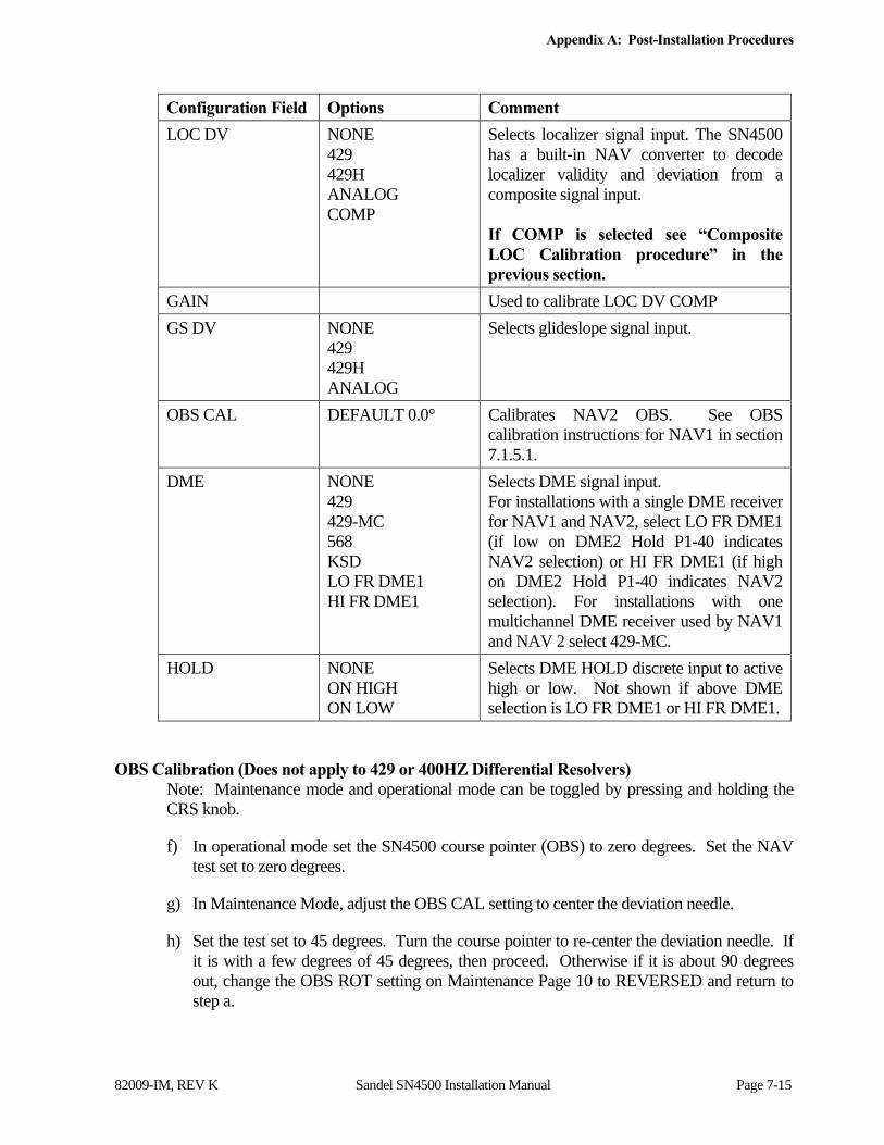
Appendix A: Post-Installation Procedures
82009-IM, REV K Sandel SN4500 Installation Manual Page 7-15
Configuration Field Options Comment
LOC DV NONE 429 429H ANALOG COMP
Selects localizer signal input. The SN4500 has a built-in NAV converter to decode localizer validity and deviation from a composite signal input. If COMP is selected see “Composite LOC Calibration procedure” in the previous section.
GAIN Used to calibrate LOC DV COMP
GS DV NONE 429 429H ANALOG
Selects glideslope signal input.
OBS CAL DEFAULT 0.0° Calibrates NAV2 OBS. See OBS calibration instructions for NAV1 in section 7.1.5.1.
DME NONE 429 429-MC 568 KSD LO FR DME1 HI FR DME1
Selects DME signal input. For installations with a single DME receiver for NAV1 and NAV2, select LO FR DME1 (if low on DME2 Hold P1-40 indicates NAV2 selection) or HI FR DME1 (if high on DME2 Hold P1-40 indicates NAV2 selection). For installations with one multichannel DME receiver used by NAV1 and NAV 2 select 429-MC.
HOLD NONE ON HIGH ON LOW
Selects DME HOLD discrete input to active high or low. Not shown if above DME selection is LO FR DME1 or HI FR DME1.
OBS Calibration (Does not apply to 429 or 400HZ Differential Resolvers) Note: Maintenance mode and operational mode can be toggled by pressing and holding the CRS knob.
f) In operational mode set the SN4500 course pointer (OBS) to zero degrees. Set the NAV test set to zero degrees.
g) In Maintenance Mode, adjust the OBS CAL setting to center the deviation needle.
h) Set the test set to 45 degrees. Turn the course pointer to re-center the deviation needle. If it is with a few degrees of 45 degrees, then proceed. Otherwise if it is about 90 degrees out, change the OBS ROT setting on Maintenance Page 10 to REVERSED and return to step a.

Appendix A: Post-Installation Procedures
82009-IM, REV K Sandel SN4500 Installation Manual Page 7-16
i) Check the to/from flag on the SN4500 display. If to/from is reversed (and correct wiring has been verified) adjust the OBS CAL 180 degrees from the current setting.
Check the course pointer at 30 degree increments and verify calibration.
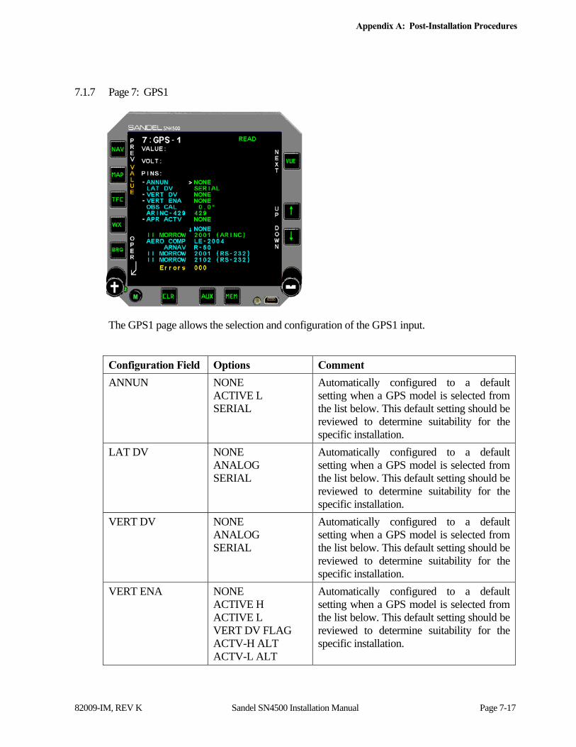
Appendix A: Post-Installation Procedures
82009-IM, REV K Sandel SN4500 Installation Manual Page 7-17
7.1.7 Page 7: GPS1
The GPS1 page allows the selection and configuration of the GPS1 input.
Configuration Field Options Comment
ANNUN NONE ACTIVE L SERIAL
Automatically configured to a default setting when a GPS model is selected from the list below. This default setting should be reviewed to determine suitability for the specific installation.
LAT DV NONE ANALOG SERIAL
Automatically configured to a default setting when a GPS model is selected from the list below. This default setting should be reviewed to determine suitability for the specific installation.
VERT DV NONE ANALOG SERIAL
Automatically configured to a default setting when a GPS model is selected from the list below. This default setting should be reviewed to determine suitability for the specific installation.
VERT ENA NONE ACTIVE H ACTIVE L VERT DV FLAG ACTV-H ALT ACTV-L ALT
Automatically configured to a default setting when a GPS model is selected from the list below. This default setting should be reviewed to determine suitability for the specific installation.

Appendix A: Post-Installation Procedures
82009-IM, REV K Sandel SN4500 Installation Manual Page 7-18
Configuration Field Options Comment
OBS CAL DEFAULT 0.0° Automatically configured when GPS is selected from list below. May require adjustment if the GPS receiver uses an RS-232 interface and has a resolver connected.
ARINC 429 429 429H
Used to select between ARINC 429 and ARINC 429 High Speed. This option is not available when a GPS receiver is selected that does not utilize an ARINC 429 interface.
APR ACTV NONE ANNUN IN ACTIVE L ACTIVE H ACTV-H ALT ACTV-L ALT
GPS approach active source select.
GPS Select from list Select the appropriate model of GPS from the list. Press the SET soft key (CLR button) to program. NOTE: any time a GPS model is selected using the SET soft key, a review of the default settings in the above configuration fields should be made to confirm that they are appropriate for the installation.
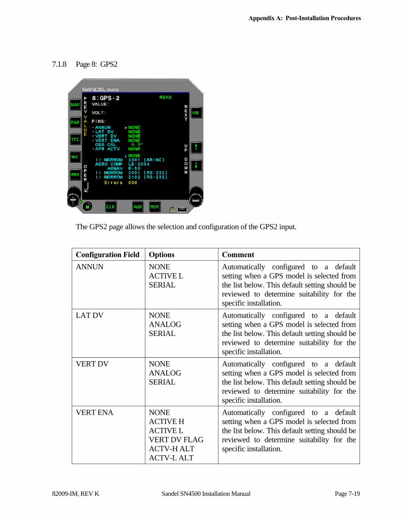
Appendix A: Post-Installation Procedures
82009-IM, REV K Sandel SN4500 Installation Manual Page 7-19
7.1.8 Page 8: GPS2
The GPS2 page allows the selection and configuration of the GPS2 input.
Configuration Field Options Comment
ANNUN NONE ACTIVE L SERIAL
Automatically configured to a default setting when a GPS model is selected from the list below. This default setting should be reviewed to determine suitability for the specific installation.
LAT DV NONE ANALOG SERIAL
Automatically configured to a default setting when a GPS model is selected from the list below. This default setting should be reviewed to determine suitability for the specific installation.
VERT DV NONE ANALOG SERIAL
Automatically configured to a default setting when a GPS model is selected from the list below. This default setting should be reviewed to determine suitability for the specific installation.
VERT ENA NONE ACTIVE H ACTIVE L VERT DV FLAG ACTV-H ALT ACTV-L ALT
Automatically configured to a default setting when a GPS model is selected from the list below. This default setting should be reviewed to determine suitability for the specific installation.
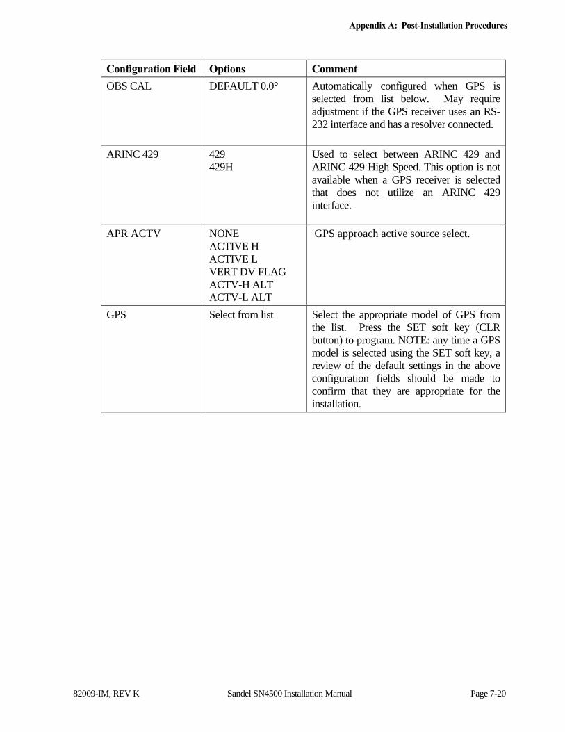
Appendix A: Post-Installation Procedures
82009-IM, REV K Sandel SN4500 Installation Manual Page 7-20
Configuration Field Options Comment
OBS CAL DEFAULT 0.0° Automatically configured when GPS is selected from list below. May require adjustment if the GPS receiver uses an RS-232 interface and has a resolver connected.
ARINC 429 429 429H
Used to select between ARINC 429 and ARINC 429 High Speed. This option is not available when a GPS receiver is selected that does not utilize an ARINC 429 interface.
APR ACTV NONE ACTIVE H ACTIVE L VERT DV FLAG ACTV-H ALT ACTV-L ALT
GPS approach active source select.
GPS Select from list Select the appropriate model of GPS from the list. Press the SET soft key (CLR button) to program. NOTE: any time a GPS model is selected using the SET soft key, a review of the default settings in the above configuration fields should be made to confirm that they are appropriate for the installation.
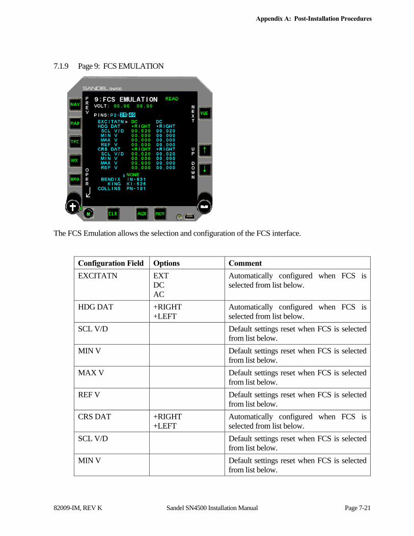
Appendix A: Post-Installation Procedures
82009-IM, REV K Sandel SN4500 Installation Manual Page 7-21
7.1.9 Page 9: FCS EMULATION
The FCS Emulation allows the selection and configuration of the FCS interface.
Configuration Field Options Comment
EXCITATN EXT DC AC
Automatically configured when FCS is selected from list below.
HDG DAT +RIGHT +LEFT
Automatically configured when FCS is selected from list below.
SCL V/D Default settings reset when FCS is selected from list below.
MIN V Default settings reset when FCS is selected from list below.
MAX V Default settings reset when FCS is selected from list below.
REF V Default settings reset when FCS is selected from list below.
CRS DAT +RIGHT +LEFT
Automatically configured when FCS is selected from list below.
SCL V/D Default settings reset when FCS is selected from list below.
MIN V Default settings reset when FCS is selected from list below.

Appendix A: Post-Installation Procedures
82009-IM, REV K Sandel SN4500 Installation Manual Page 7-22
Configuration Field Options Comment
MAX V Default settings reset when FCS is selected from list below.
REF V Default settings reset when FCS is selected from list below.
FCS Select from list Select the appropriate emulation from the list. Press the SET soft key (CLR button) to program.
HDG V/D and CRS V/D increase or decrease the gain of the course or heading error relative to the lubber line, and normally match the volts/degree input of the associated autopilot computer. These values default when the FCS selection is initially set, but can be adjusted in-flight if necessary, in VFR conditions, as follows:
a) Engage the autopilot in HDG mode. After the aircraft is established on the desired heading, move the heading bug knob a large amount and ensure that the aircraft turns to the heading bug and rolls out normally without instability, overshooting or undershooting to the desired heading. To correct for overshooting or instability, reduce the HDG V/D setting. To correct for undershooting, increase the HDG V/D setting.
b) Engage the autopilot in NAV mode and turn off the NAV receiver to provide a zero course error. Repeat the tests and adjustments above using the course pointer and adjust the CRS V/D setting as appropriate.
c) Use the REF V adjustment to center the heading and Course rollout if not precisely on the lubber line. This will rarely be required.
HDG DAT and CRS DAT allow the direction sensing to be reversed during installation. Changing these settings is identical to reversing H/C on a synchro control transformer.
The other settings on this page are not for installer adjustment except on advice of the factory, service bulletin, or service information letter.
Note that the adjustments are shown in the left column of values. The right column shows the default values for reference purposes.

Appendix A: Post-Installation Procedures
82009-IM, REV K Sandel SN4500 Installation Manual Page 7-23
7.1.10 Page 10: OBS / Relay / CDI
Configuration Field Options Comment
OBS ROT NORMAL REVERSED DIFF A
Adjusts rotation of OBS. Select DIFF A when interfaced to 400HZ differential resolver.
RMT CRS XYZ
RMT HDG XYZ
BTSTRP NONE NORMAL REVERSE
Enables bootstrap synchro heading output.
MODE MASTER SLAVE
Selects NAV/GPS switching mode. In MASTER mode, the SN4500’s NAV button is used to switch between NAV and GPS sources. In SLAVE mode a remote switch is used.

Appendix A: Post-Installation Procedures
82009-IM, REV K Sandel SN4500 Installation Manual Page 7-24
Configuration Field Options Comment
SENSE NONE GPS1 GPS2 GPS1/GPS2 NAV2 GPS1/NAV2 GPS2/NAV2 G1/G2/N2
Enables relay sense input to verify relay switching. If a low is not detected on the relay sense input, the corresponding NAV source will be redlined on the pilot’s display when selected.
NS GPS2 GPS2 NAV2 & GPS2
Normal operation of sense lines as described above in Sense selections. Use this selection and “NAV2” in Sense selections for installations with dual Garmin GNS Receivers where both receivers (All four NAV sources) are made available as NAV sources. This is the sense input (P3-5) for a relay which is wired to both the NAV-2 and GPS-2 relay outputs.
ILS LCK DISABLE ENABLE
Enables/disables ILS Lockout feature of the ILS input for NAV1/NAV2.
AUTOSLEW OFF NORMAL ON
Enables or disables the Pilot Menu selection of the AUTOSLEW feature. When set to OFF: AUTOSLEW is not available. When set to NORMAL: AUTOSLEW is pilot selectable in the Pilot Menu. When set to ON: 1) the AUTOSLEW feature is forced on. There is no selection available in the Pilot Menu. 2) During OBS operations course selection is from GPS navigator.
OBS NORMAL REMOTE
When GPS is in OBS mode: NORMAL: CRS select from CRS knob or GPS. REMOTE: CRS select from GPS only (use for tandem training installations). The GPS/FMS must be configured to not accept external input for selected course.
LAT DEV n/a Monitors FCS voltage outputs.
OFFSET n/a Adjusts zero offset of the lateral deviation output*
VERT DV n/a Monitors FCS voltage outputs.
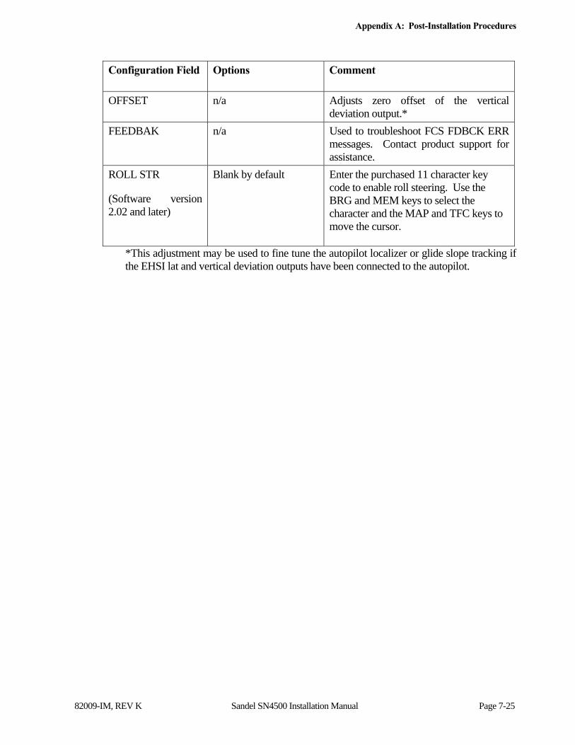
Appendix A: Post-Installation Procedures
82009-IM, REV K Sandel SN4500 Installation Manual Page 7-25
Configuration Field Options Comment
OFFSET n/a Adjusts zero offset of the vertical deviation output.*
FEEDBAK n/a Used to troubleshoot FCS FDBCK ERR messages. Contact product support for assistance.
ROLL STR
(Software version 2.02 and later)
Blank by default Enter the purchased 11 character key code to enable roll steering. Use the BRG and MEM keys to select the character and the MAP and TFC keys to move the cursor.
*This adjustment may be used to fine tune the autopilot localizer or glide slope tracking if the EHSI lat and vertical deviation outputs have been connected to the autopilot.
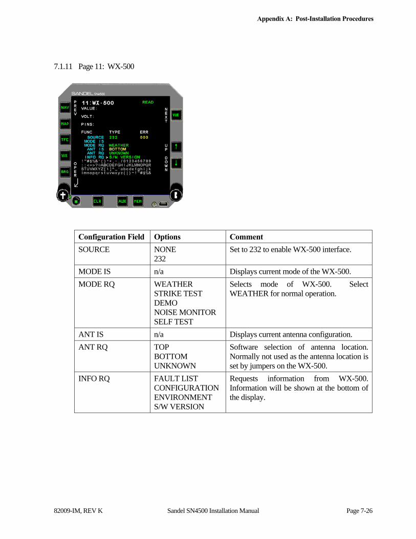
Appendix A: Post-Installation Procedures
82009-IM, REV K Sandel SN4500 Installation Manual Page 7-26
7.1.11 Page 11: WX-500
Configuration Field Options Comment
SOURCE NONE 232
Set to 232 to enable WX-500 interface.
MODE IS n/a Displays current mode of the WX-500.
MODE RQ WEATHER STRIKE TEST DEMO NOISE MONITOR SELF TEST
Selects mode of WX-500. Select WEATHER for normal operation.
ANT IS n/a Displays current antenna configuration.
ANT RQ TOP BOTTOM UNKNOWN
Software selection of antenna location. Normally not used as the antenna location is set by jumpers on the WX-500.
INFO RQ FAULT LIST CONFIGURATION ENVIRONMENT S/W VERSION
Requests information from WX-500. Information will be shown at the bottom of the display.

Appendix A: Post-Installation Procedures
82009-IM, REV K Sandel SN4500 Installation Manual Page 7-27
7.1.12 Page 12: Traffic & WXDL
Configuration Field Options Comment
DATA LINK WSI w / TX WSI no TX
SN4500 is sole display. SN4500 is wired as receive only, another display is connected to the WSI receiver.
DLINK KEY Blank by default Enter the purchased 11 character key code to enable data link weather. Use the BRG and MEM keys to select the character and the MAP and TFC keys to move the cursor.
TCAS KEY Blank by default Enter the purchased 11 character key code to enable traffic. Use the BRG and MEM keys to select the character and the MAP and TFC keys to move the cursor.
TCAS Model Collins TCAS 4000 Goodrich Skywatch HP Goodrich TCAS791/A Honeywell CAS-66 Honeywell CAS-67 Honeywell CAS-81 Ryan 9900BX TAS
Select the appropriate model of TCAS from the list. Press the SET soft key (CLR button) to program. NOTE: Users of Honeywell KTA-810 systems should configure as CAS-66.
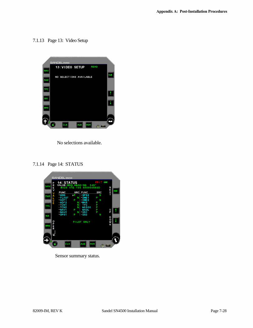
Appendix A: Post-Installation Procedures
82009-IM, REV K Sandel SN4500 Installation Manual Page 7-28
7.1.13 Page 13: Video Setup
No selections available.
7.1.14 Page 14: STATUS
Sensor summary status.

Appendix A: Post-Installation Procedures
82009-IM, REV K Sandel SN4500 Installation Manual Page 7-29
7.1.15 Page 15: BRT/DATA BLK
Provides information regarding backlight color temperature. Configures the brightness controls for the buttons and the display.
Configuration Field Options Comment
BACKLIGHT None Monitors display color temperature.
Input Mode Internal 28VDC 5VDC 5VAC
Select this option when no external dimming control is to be used. Select 28VDC, 5VDC, or 5VAC – as appropriate – when an external dimming control is to be used.
Max Brt Adjusts voltage threshold for maximum display brightness. Option is not available when internal input mode is selected.
Min Brt Norm Adjusts voltage threshold for minimum display brightness. Option is not available when internal input mode is selected.
Min Brt NVIS Adjusts voltage threshold for minimum display brightness while in NVIS mode. Option is not available when internal input mode is selected.
Manual Brt Req Measurement of current manual brightness setting. (1000 = full bright.)
Dim Bus In (P1-21) Current voltage at pin P1-21.

Appendix A: Post-Installation Procedures
82009-IM, REV K Sandel SN4500 Installation Manual Page 7-30
LT Threshold Sets the ambient light threshold at which the Auto Brightness control will display full brightness. Set Pilot Trim to 0 then set this number to the current Cockpit Brt reading when in the desired ambient light level that represents the transition to full brightness.
Scrn Brt Req None Represents the brightness leve (0-l that is being commanded by the software.
Cockpit Brt None Indicates cockpit brightness level as read by light sensor
NVIS CONTROL None Monitors NVIS control signal.
Recorded Data None Contact Sandel for information about downloading flight data for analysis.
Calibrating the external brightness control:
NOTE: 1) Default values are displayed in the Max Brt, Min Brt Norm, and Min Brt NVIS fields - for each available bus voltage (5V DC, 5V AC, and 28V DC). 2) If changes are made to the default values of any of the Max Brt, Min Brt Norm, and Min Brt NVIS fields - and then any changes are made to the Input Mode field, the non-default values will be lost and will have to be reentered. 3) The maintenance page always displays at 100% brightness. You need to exit MAINT by pressing and holding the left knob to see the resulting brightness adjustment.
BEFORE performing calibration: Select the “BRT/DATA BLK” maintenance page; select the correct EXTERNAL voltage bus value for Manual Brightness control. To calibrate maximum brightness: Set aircraft to NVIS off and do the following from the BRT/DATA BLK maintenance page: 1. Select “Max Brt” with up/down arrow keys. 2. Set the aircraft external brightness bus to the maximum brightness setting. 3. Press the “SET” softkey to set the “Max Brt” setting to a value equal to the voltage shown in the “Dim Bus In” field. To calibrate minimum brightness: Set aircraft to NVIS OFF and do the following from BRT/DATA BLK maintenance page: 1. Select “Min Brt Norm” with up/down arrow keys 2. Set the aircraft external brightness bus at the desired night-brightness voltage. This voltage will be displayed on-screen.
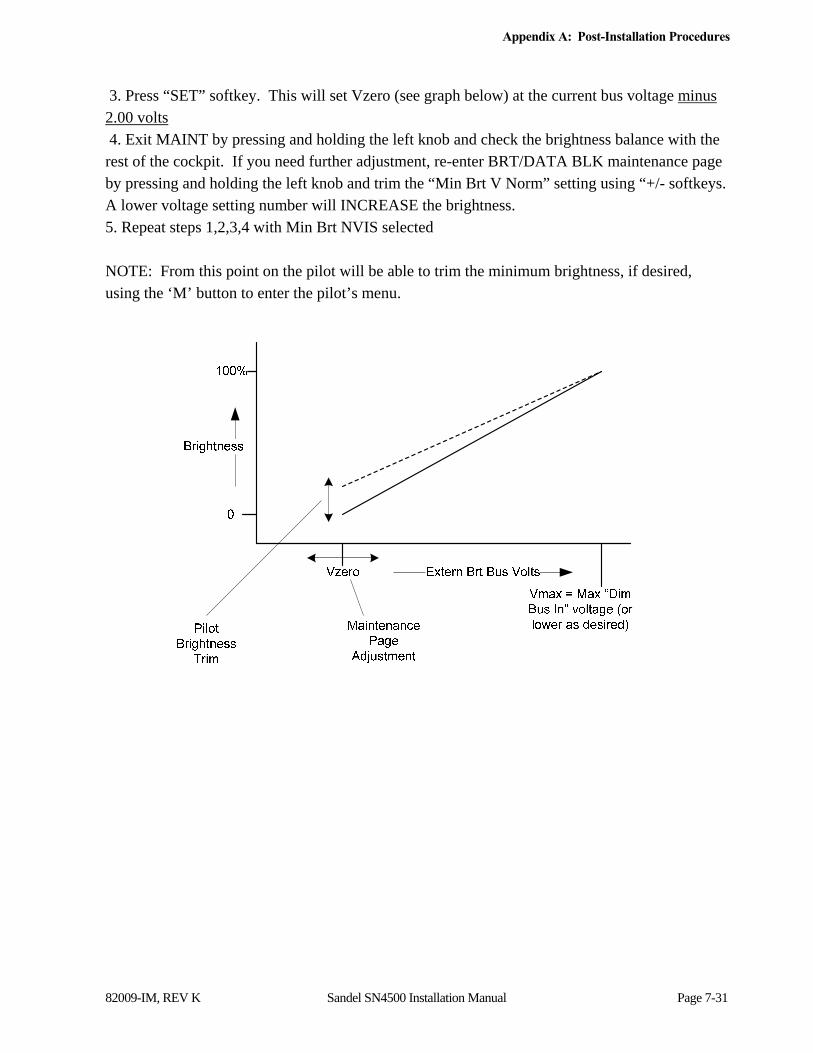
Appendix A: Post-Installation Procedures
82009-IM, REV K Sandel SN4500 Installation Manual Page 7-31
3. Press “SET” softkey. This will set Vzero (see graph below) at the current bus voltage minus 2.00 volts 4. Exit MAINT by pressing and holding the left knob and check the brightness balance with the rest of the cockpit. If you need further adjustment, re-enter BRT/DATA BLK maintenance page by pressing and holding the left knob and trim the “Min Brt V Norm” setting using “+/- softkeys. A lower voltage setting number will INCREASE the brightness. 5. Repeat steps 1,2,3,4 with Min Brt NVIS selected NOTE: From this point on the pilot will be able to trim the minimum brightness, if desired, using the ‘M’ button to enter the pilot’s menu.
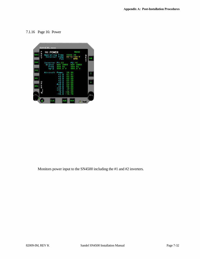
Appendix A: Post-Installation Procedures
82009-IM, REV K Sandel SN4500 Installation Manual Page 7-32
7.1.16 Page 16: Power
Monitors power input to the SN4500 including the #1 and #2 inverters.
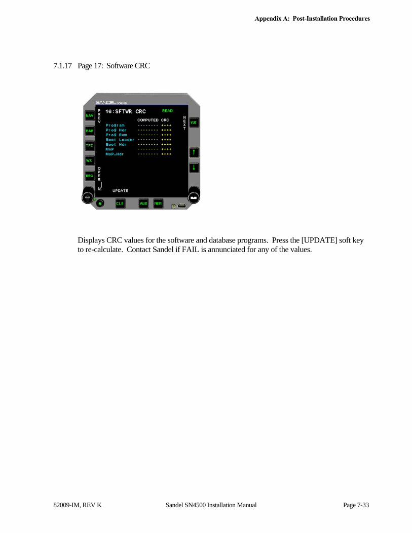
Appendix A: Post-Installation Procedures
82009-IM, REV K Sandel SN4500 Installation Manual Page 7-33
7.1.17 Page 17: Software CRC
Displays CRC values for the software and database programs. Press the [UPDATE] soft key to re-calculate. Contact Sandel if FAIL is annunciated for any of the values.

APPENDIX B: ENVIRONMENTAL QUALIFICATION
82009-IM, REV K Sandel SN4500 Installation Manual Page 8-1
8 Appendix B: Environmental Qualification
RTCA/D0-160E Environmental Qualification
NAMEPLATE NOMENCLATURE: [(A2)(F1)Z]BAB[HR]XXXXXXZBABBC[WW]M[XXE2F2X]XXAX
TYPE/MODEL NO: SN4500 TSO NUMBERS: C113, -C6d, -C34e, -C35d, -C36e, -C40c, -C41d, -C118, -C119b
MANUFACTURER’S SPECIFICATION AND/OR OTHER APPLICABLE SPECIFICATION:
a.) System Requirements For Model SN4500 Navigation Display, document number 82009-0010
b.) Sandel SN4500 RTCA D0-160E Environmental Test Plan, document number 82009-0090
c.) Sandel SN4500 EHSI Environmental Test Credit Analysis, document number 82009-0144
MANUFACTURER: Sandel Avionics, Inc.
ADDRESS: 2401 Dogwood Way
Vista, CA 92081
REVISION & CHANGE NOS. OF D0-160: Revision E DATE TESTED: 11/12/05-12/14/05
ENVIRONMENTAL TESTS RTCA/DO-160E SECTION Equipment Test Category Temperature & Altitude
Low Temperature -Ground Survival -Operational
High Temperature -Ground Survival -Operational
In-Flight Loss of Cooling Altitude
-Decompression -Overpressure
4.0 4.5.1 & 4.5.2
4.5.3 & 4.5.4
4.5.5 4.6.1 4.6.2 4.6.3
[(A2)(F1)]
Z [(A2)(F1)]
Temperature Variation 5.0 B Humidity 3.1 A Operational Shock and Crash Safety 0 B Vibration 8.0 [H R] Explosion 9.0 X Water-Proofness 10.0 X Fluids Susceptibility 11.0 X Sand and Dust 12.0 X Fungus 13.0 X Salt Spray 14.0 X Magnetic Effect 15.0 Z Power Input 16.0 B Voltage Spike 17.0 A Audio Frequency Susceptibility 18.0 B Induced Signal Susceptibility 19.0 BC Radio Frequency Susceptibility 20.0 [WW] Radio Frequency Emission 21.0 M Lightning Susceptibility 22.0 [XXE2F2X] Lightning Direct Effects 23.0 X Icing 24.0 X Electrostatic Discharge 25.0 A Fire, Flammability 26.0 X

Appendix C: Sample FAA Form 337
82009-IM, REV K Sandel SN4500 Installation Manual Page 9-1
9 Appendix C: Sample FAA Form 337
NOTICE
Weight and balance or operating limitation changes shall be entered in the appropriate aircraft record. An alteration must be compatible with all previous alterations to assure continued conformity with the applicable airworthiness requirements.
8. Description of Work Accomplished (If more space is required, attach additional sheets. Identify with aircraft nationality and
registration mark and date work completed.) A. Installed the following equipment and components: 1. Sandel Avionics, Inc., SN4500 Navigation Display (or as appropriate), Part Number
SN4500-000 (or as appropriate) 2. Sandel Avionics, Inc., Clamp Fixture 4ATI, Part Number 61186. B. The Sandel Avionics SN4500 is interfaced to the following equipment: 1. Garmin International, GPS165, GPS Navigation Receiver (Approved for En route,
Terminal, and Non-precision Approach). (or as appropriate) 2. AlliedSignal Electronics and Avionics, KX 165 Communications and Navigation
Receiver. (or as appropriate) 3. AlliedSignal Electronics and Avionics, KX 155 Communications and Navigation
Receiver. (or as appropriate) 4. AlliedSignal Electronics and Avionics, KRA 10A Radar Altimeter System. (or as
appropriate) 5. AlliedSignal Electronics and Avionics, KR 22 Marker Receiver. (or as appropriate) 6. AlliedSignal Electronics and Avionics, KG 102A Directional Gyro. (or as
appropriate) 7. AlliedSignal Electronics and Avionics, KMT 112 Magnetic Azimuth Transmitter. (or
as appropriate) (By example state the following functional interface properties)... C. The SN4500 receives and processes GPS navigation information for digital and waypoint
display from the GPS165. These operations are considered supplemental navigation. D. The SN4500 receives and processes VOR, localizer, and glideslope deviation and

Appendix C: Sample FAA Form 337
82009-IM, REV K Sandel SN4500 Installation Manual Page 9-2
composite audio for bearing display from the KX 165. These operations are considered primary means of navigation.
E. The SN4500 receives and processes glideslope deviation and composite audio for bearing
display from the KX 155. F. The SN4500 receives and processes marker beacon receiver information for illumination
from the KR 22. G. The SN4500 receives and processes magnetic heading for digital and graphic display from
the KG 102A and KMT 112. H. Interference and functional tests and inspections were accomplished with reference to
Advisory Circular 23.1311. (or as appropriate). I. A system design and analysis was conducted with reference to Advisory Circular 2X.1309-
1( ). (or as appropriate). J. Federal Aviation Regulations, 2X.1301, 2X.1309(a), (b) and (d), 23.1311, 2X.1321(a), (b)
and (d), 2X.1322, 2X.1327(a), 2X.1331, 2X1351, 2X.1357(a)-(d), 23.1365, 2X.1381, 2X.1529, and 2X.1581 (or as appropriate), were the basis of compliance.
K. Installation approval is sought with reference to Flight Standards Information Bulletin,
FSAW 95-09( ) (Amended), titled “Electronic Horizontal Situation Indicator (EHSI) Approvals”.
L. The aircraft equipment list, and weight and balance were revised and recorded within the
aircraft maintenance records.
All pertinent records of this alteration are on file at (State your repair station name and number).
-------------------------------------------------------- End ------------------------------------------------

Appendix D: Sample Airplane Flight Manual Supplement
82009-IM, REV K Sandel SN4500 Installation Manual Page 10-1
10 Appendix D: Sample Airplane Flight Manual Supplement
The following is being provided for installations in which the local FSDO requires an Airplane Flight Manual Supplement. This Sample is simply being provided for the convenience of the installer. Note that the cover page, table of contents and log of revisions has not been included here, and will be specific to your installation. The text is specific to the installed equipment, and also specifies ILS LOCKOUT operation. This text must be modified by the installation facility to be compatible with the installed equipment.
SECTION I – GENERAL
The Sandel Avionics SN4500 Primary Navigation Display is a compact four-inch instrument that performs the functions of a traditional Horizontal Situation Indicator combined with a two-pointer RMI. The SN4500 also displays a moving map, Stormscope data, FIS-B data link weather, traffic information, marker beacon and GPS annunciators if the aircraft is appropriately equipped and configured.
Add following text if Data Link Weather is installed: FIS-B Weather Data is intended for the purpose of assisting in long-range strategic flight planning only. Please note that its delayed updating and lack of sufficient resolution makes it unsuitable for tactical maneuvering of the aircraft. It also differs significantly from on-board weather radar (which scans a narrow vertical angle) since it portrays radar returns from multiple ground stations extending from the surface up to the highest flight levels. For these reasons it may not even directly reflect the current flight conditions.
SECTION II LIMITATIONS
The system must utilize software version 1.01 or later FAA approved version.
The SN4500 Primary Navigation Display Pilots Guide, SPN 82009-PG (or applicable revision corresponding to the software version) must be immediately available to the flight crew.
The “CRC Self Test Failed” message must not appear on power-up if flight operations are predicated on the use of the SN4500.
Add following text if Data Link Weather is installed: The FIS-B weather display shall not be used for tactical maneuvering of the aircraft.
SECTION III EMERGENCY PROCEDURES
If the SN4500 fails to operate, use the magnetic compass as a heading source.
If the remote directional gyro (DG) becomes inoperative, the magnetic fluxgate will provide the heading, and the resulting heading display will respond much more slowly than normal. The compass rose changes color from white to amber, and digital heading numbers will be redlined.
Appendix D: Sample Airplane Flight Manual Supplement
82009-IM, REV K Sandel SN4500 Installation Manual Page 10-2
If the fluxgate fails, the SN4500 will continue to display heading based on the directional gyro (DG) input. The compass rose changes color from white to amber, heading numbers will be redlined.
If the remote directional gyro (DG) fails and the fluxgate fails or the SN4500 is a slaved heading repeater, the compass rose will change from white to amber and continue to be displayed and the digital heading numbers will be redlined. Use the magnetic compass as a heading source.
If the “FCS FDBCK ERR” message appears when in autopilot coupled NAV or APPR mode, immediately monitor the lateral and vertical deviation indicators. If they are not tracking properly, immediately disable the autopilot and flight director NAV or APPR mode for the duration of the flight. HDG mode may still be used if the autopilot tracks the SN4500 HDG bug properly.
SECTION IV NORMAL PROCEDURES
The SN4500 NAV pushbutton selects the primary navigation source NAV1, NAV2 or GPS1. The selected source will drive the SN4500 deviation indicator and the autopilot.
ILS override will prevent selection of the GPS as long as an ILS frequency is tuned on NAV1 or NAV2. This will be annunciated on the SN4500 Navigation Display.
The SN4500 BRG pushbutton selects the bearing pointer 1 / 2 / both. The ‘M’ pushbutton followed by the BRG pushbutton selects the bearing pointer sources NAV1, NAV2, GPS1, GPS2, or ADF.
Annunciation of all GPS modes is accomplished by messages on the GPS receiver as well as on-screen annunciation on the SN4500.
[If installed as a heading repeater (no direct fluxgate connection).]
When manually slewing the remote compass system, the compass rose will change from white to amber and the digital heading numbers will be relined.
[End heading repeater language.]
Add following text if Traffic is installed: The traffic display mode is annunciated next to the TFC button. There are three different modes available which control how the traffic targets are displayed. Press the TFC button repeatedly to cycle through the different modes.
ON: Enables display of all targets within the selected map range (limited by the maximum range of the installed traffic system).
M: Manual mode. Traffic will be displayed at the selected map range only when alerting traffic is present, without auto ranging. Display range can be changed manually.
A: Auto mode. Traffic will be displayed at the selected map range only when alerting traffic is present, except that the map range will auto-scale to an appropriate range to show the traffic on-screen.
Appendix D: Sample Airplane Flight Manual Supplement
82009-IM, REV K Sandel SN4500 Installation Manual Page 10-3
Manual (M) or Auto (A) modes do not display non-alerting traffic.
Add following text if Data Link Weather is installed: The SN4500 can display two types of weather information, precipitation and lightning. Lightning may be displayed from two independent sources, WX-500 Stormscope or a FIS-B data link receiver. Both sources of lightning may be displayed simultaneously.
The SN4500 WX pushbutton selects the type weather to be displayed:
PL: Precipitation & Lightning
P: Precipitation only
L: Lightning only
The ‘M’ pushbutton followed by the WX pushbutton selects the lightning display data source, either WX500, WSI, or both. The number to the right of the WX annunciation displays the time in minutes since the last FIS-B precipitation data was received from the data link receiver.
Weather graphics depicted on the SN4500 data link weather display may differ significantly from the on-board weather radar or from out of the cockpit observations for one or more of the following reasons.
Vertical strata information is not provided by the FIS-B weather service. The FIS-B weather data originates from NEXRAD ground based weather radar observations that include weather measurements up to 30,000 feet above the radar facility. The on-board weather radar is measuring returns relative to the current flight level.
The FIS-B weather display is not exactly real time. Under certain circumstances the time from when the NEXRAD radar observations were made to when the data is displayed on the SN4500 can be as high as 40 minutes. During this time the position of the weather may have significantly changed or moved relative to the aircraft position.
The graphic representation of precipitation is predicated on the level of reflected energy from moisture in the air mass (the more moisture in the air mass, the higher level of energy returned to the radar antenna). This may result in graphic presentation of precipitation on the SN4500 display when no visible moisture can be seen.
Virga precipitation: the precipitation may be at a higher flight level and evaporating before reaching the current aircraft flight level.
The circuit breaker for the SN4500 is located on the lower right circuit breaker panel labeled EHSI 1.
Refer to the SN4500 Pilot’s Guide for other procedures, error messages, alerts and more detailed FIS-B data link weather information.
Add following text if Reversionary Attitude is installed: Pilot Integrity Check

Appendix D: Sample Airplane Flight Manual Supplement
82009-IM, REV K Sandel SN4500 Installation Manual Page 10-4
The attitude data source in Reversionary Mode is received from the same AHRS which supplies the HSI heading, typically a Sandel SG102. In order to assure that the reversionary attitude capability is working and available, this feature should be checked each flight prior to takeoff by activating the REV switch and comparing the display against the other aircraft attitude instruments. During normal flight, if the HSI heading is intermittent erroneous or flagged, it may indicate that Reversionary Mode may be unavailable. Reversionary Mode may be tested at any time by activating the REV switch and comparing against the other aircraft attitude instruments. Note: Due to the differences in operational characteristics between the AHRS and the other attitude gyros, the Reversionary Mode attitude may differ slightly from the other attitude instruments during or just after maneuvers. This difference should wash out after the aircraft returns to level flight with the slip-skid ball centered. This slight attitude difference during maneuvering should be considered normal.
SECTION V PERFORMANCE DATA
No Change to AFM.
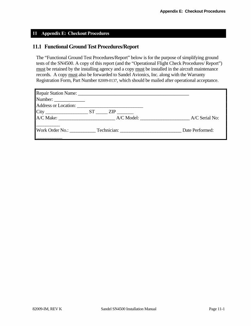
Appendix E: Checkout Procedures
82009-IM, REV K Sandel SN4500 Installation Manual Page 11-1
11 Appendix E: Checkout Procedures
11.1 Functional Ground Test Procedures/Report
The “Functional Ground Test Procedures/Report” below is for the purpose of simplifying ground tests of the SN4500. A copy of this report (and the “Operational Flight Check Procedures/ Report”) must be retained by the installing agency and a copy must be installed in the aircraft maintenance records. A copy must also be forwarded to Sandel Avionics, Inc. along with the Warranty Registration Form, Part Number 82009-0137, which should be mailed after operational acceptance.
Repair Station Name: _______________________________________________ Number: _____________ Address or Location: ____________________________ City __________________ ST _____ ZIP _______ A/C Make: ________________________ A/C Model: _____________________ A/C Serial No: __________ Work Order No.: ___________ Technician: __________________________ Date Performed: ___________

Appendix E: Checkout Procedures
82009-IM, REV K Sandel SN4500 Installation Manual Page 11-2
COMPANY NAME COMPANY ADDRESS TELEPHONE/FAX
Ground Test Procedures/Report for
Sandel Avionics SN4500
Installed in Aircraft make and model
Registration No. _____________ Serial No. ______________
Document No. ____________ Rev. - , Date
Appendix E: Checkout Procedures
82009-IM, REV K Sandel SN4500 Installation Manual Page 11-3
11.1.1 Introduction
The following ground test procedures are to be performed after the SN4500 has been properly configured in the “Post-Installation Procedures”, but prior to performing flight test procedures. Successful completion of both the Ground Test and Flight Test procedures is necessary to support the claim that the SN4500, as installed, performs its intended function and is compatible with all aircraft systems. The ground test procedures contained herein will include testing of interfaces to other systems. Therefore, this ground test must be conducted in conjunction with, or subsequent to ground testing of other systems.
The following external system interfaces will be tested:
- Heading input from directional gyro
- Compass input from fluxgate sensor (if installed)
- Navigation data inputs: VOR/TCN/ILS/GS, ADF, DME, GPS and FMS (if installed)
- Annunciator inputs from a marker beacon receiver (if installed)
- Annunciator inputs from a GPS receiver (if installed)
- Lightning-strike inputs from a WX-500 Stormscope® sensor (if installed)
- Remote NAV source switching relays and/or indicators (if installed)
- External NVIS control switch (if installed)
11.1.2 Test Procedures and Results
11.1.2.1 Physical Installation
Verify that the SN4500 clamp has been properly installed in accordance with the manufacturer’s instructions, that any external switches affecting SN4500 operation have been clearly labeled, and that a trip-free re-settable circuit breaker labeled “EHSI” is clearly visible. Ensure that cooling air intake is not obstructed.
Completed _______ Comment __________________________________
11.1.2.2 Wiring Verification and Initial Power-Up
Perform a 100% continuity check of all aircraft wiring to verify in accordance with installation wiring diagrams.
Completed _______ Comment __________________________________

Appendix E: Checkout Procedures
82009-IM, REV K Sandel SN4500 Installation Manual Page 11-4
Power check all wiring to ensure that 28 Vdc and 26 Vac (if applicable) are applied to the proper pins and nowhere else.
Completed _______ Comment __________________________________
Install the SN4500 into the clamp tray and verify full connector mating and that the unit installs without obstruction.
Completed _______ Comment __________________________________
Activate the aircraft master switch and avionics master switch, if installed. Verify that the SN4500 display illuminates within 30 seconds.
Switch on all equipment interfaced to the SN4500 such as NAV receivers, gyros, and marker beacon receivers.
Completed _______ Comment __________________________________
11.1.2.3 System Configuration
If not previously accomplished, perform the “Post-Installation Procedures” included in the Appendix of the SN4500 Installation Guide. These procedures describe how to configure the SN4500 for compatibility with installed systems.
Completed _______ Comment __________________________________
11.1.2.4 System Functions
11.1.2.5 Compass System Interface
Power up the system and verify that within 3 minutes the compass card is displayed in white and agrees with the heading on a magnetic compass.
Completed _______ Comment __________________________________
Disable the fluxgate excitation to the SN4500. Verify that within 10 seconds the compass digital heading is flagged. Restore the fluxgate excitation and verify that within 10 seconds the display is fully restored. Note: If fluxgate excitation and gyro are interconnected, remove both signals simultaneously and look for simultaneous failure indications.)
Appendix E: Checkout Procedures
82009-IM, REV K Sandel SN4500 Installation Manual Page 11-5
Completed _______ Comment __________________________________
Remove power to (or otherwise disable) the remote directional gyro. Verify that the compass card is displayed in amber and that a warning message is displayed on the SN4500 which requires operator acknowledgement.
Completed _______ Comment __________________________________
If the SN4500 is installed as a heading repeater (no direct fluxgate connection) and interfaced with a Directional Gyro (DG) that “Flags Invalid” when operated in “Free Gyro Mode”. Verify that the SN4500 continues to display the compass rose while the gyro compass is manually slewed left and right. This test must be performed after the SN4500 has been powered for a minimum of 4 minutes.
Completed _______ Comment __________________________________
11.1.2.6 NAV Source Selection
If the SN4500 is configured in “master” mode (no external NAV/GPS switch):
Press the [NAV] button repeatedly and verify that the screen legend next to the button cycles correctly through the configured NAV sources, i.e. NAV1, NAV2, GPS1, GPS 2, TACAN 1, TACAN 2 (or as configured). For each NAV source, create valid and invalid NAV conditions and verify correct display of the SN4500 NAV flag for each receiver (the large red “X” through the CDI). For each VOR/LOC source, verify that tuning an ILS frequency causes the glideslope (vertical deviation) scale to display on the screen, even if it is flagged.
Completed _______ Comment __________________________________
[If ILS Lockout is enabled] Press the [NAV] button and select a source other than NAV1, such as GPS or NAV2 (if configured). Tune NAV1 to an ILS frequency, and verify that after a one-second delay, the selected NAV source automatically reverts to NAV1. Verify that as long as NAV1 is tuned to an ILS frequency, pressing the [NAV] button will not change the NAV source, but instead will display the message “NAV1 TUNED TO LOC”. Verify that upon de-tuning the ILS frequency from NAV1, the NAV source selection returns to its original state.
Completed _______ Comment __________________________________
If NAV2 is configured, tune both NAV1 and NAV2 to an ILS frequency and verify that
Appendix E: Checkout Procedures
82009-IM, REV K Sandel SN4500 Installation Manual Page 11-6
NAV1 remains selected. Detune the ILS frequency on NAV1 and verify that the display reverts to NAV2.
Completed _______ Comment __________________________________
If the SN4500 is configured in “slave” mode (using external NAV/GPS switch):
Verify that pressing NAV does not change the selected NAV source, but instead displays an advisory message.
Completed _______ Comment __________________________________
Verify that the external NAV/GPS switch arrangement correctly controls the selected NAV source on the SN4500, including any ILS lockout scheme, if implemented.
Completed _______ Comment __________________________________
11.1.2.7 LOC/GS Deviation
Using a ILS test signal generator verify proper deviation of the LOC/GS deviation indicators on the SN4500. Tune the NAV1 to match the ILS test signal generator frequency (usually 108.1 MHz.). Select LOC 1 on the SN4500. Adjust the signal generator to verify the following indications on the SN4500 LOC deviation indicator, center, 2 dots fly left, 2 dots fly right, and LOC flagged. Adjust the signal generator to verify the following indications on the SN4500 GS deviation indicator, center, 2 dots fly up, 2 dots fly down, and GS flagged. Repeat for NAV2.
Completed _______ Comment _________________________________
11.1.2.8 BRG Source Selection
Press M and then press BRG on the SN4500 and verify that all installed NAV sources are presented for each bearing pointer (NAV1, NAV2, TCN 1, TCN2, ADF1, ADF2, GPS1, GPS2 as installed). In addition, bearing pointer 1 will have “AUTO” listed as a choice.
Completed _______ Comment __________________________________
Select each available NAV source for each pointer, and verify in turn that the depicted bearing corresponds to the actual bearing shown on the NAV source.
Completed _______ Comment __________________________________

Appendix E: Checkout Procedures
82009-IM, REV K Sandel SN4500 Installation Manual Page 11-7
11.1.2.9 DME Selection
If two DME receivers are installed and configured:
Verify that pushing NAV to select between NAV1 and NAV2 also switches the appropriate DME readout on the SN4500 distance display. Press M and then BRG to configure bearing pointer 1 to be NAV1 and bearing pointer 2 to be NAV2. Press BRG to display both pointers simultaneously. Verify that the correct DME data is displayed in each bearing pointer data block.
Completed _______ Comment __________________________________
If a single DME receiver is installed and is not switchable between NAV1 and NAV2:
Verify that pushing NAV to select between NAV1 and NAV2 causes the DME readout to be displayed when NAV1 is selected, and the DME readout to be removed when NAV2 is selected. Press M and then press BRG to configure bearing pointer 1 to be NAV1 and bearing pointer 2 to be NAV2. Press BRG to display both pointers simultaneously. Verify that DME data is displayed in the bearing pointer 1 data block, and that no distance data is displayed in the bearing pointer 2 data block.
Completed _______ Comment __________________________________
If a single DME receiver is installed and is switchable between NAV1 and NAV2:
Verify that pushing NAV to select between NAV1 and NAV2 causes either the correct DME readout to be displayed or a “none” indication, depending on the position of the external DME select switch (if installed). Press M and then press BRG to configure bearing pointer 1 to be NAV1 and bearing pointer 2 to be NAV2. Press BRG to display both pointers simultaneously. Verify that DME data is displayed in the bearing pointer 1 data block when DME is externally switched to NAV1. Verify that when DME is externally switched to NAV2, an arrow (“”) appears in the DME portion of the pointer 1 data block, and that DME distance data is displayed in the bearing pointer 2 data block. Press BRG to deselect pointer 1 and only display pointer 2. Verify that proper DME data is now displayed in the bearing pointer 2 data block.
Completed _______ Comment __________________________________
If an external DME HOLD control is configured:
Verify that enabling DME HOLD displays the “H” symbol for each installed DME receiver so equipped.
Completed _______ Comment __________________________________
Appendix E: Checkout Procedures
82009-IM, REV K Sandel SN4500 Installation Manual Page 11-8
11.1.2.10 GPS Interface and Control
For each GPS receiver installed and configured:
Allow the receiver to acquire a valid position fix, and press NAV on the SN4500 to select that receiver as a NAV source. Enter either a single destination waypoint or a flight plan on the GPS receiver and select normal (LEG) navigation mode. Verify that the course pointer automatically rotates to the desired track, and that groundspeed and waypoint ID are displayed on the SN4500.
Completed _______ Comment __________________________________
Press M and then press BRG and assign either bearing pointer to the selected GPS receiver. Verify that the bearing pointer corresponds to the bearing-to-waypoint, and that the distance displayed matches the display on the actual receiver.
Completed _______ Comment __________________________________
If the GPS is equipped with an OBS mode (Bendix/King) or a HOLD mode which enables course resolver input (Garmin), select the OBS or HOLD mode and verify that rotating the course select knob turns the course pointer. Verify that the needle centers on the correct bearing to waypoint.
Completed _______ Comment __________________________________
Enter the “CDI and Annunciator Test” mode of the GPS if available. Verify proper response of the GPS annunciators, if configured to display on the SN4500. If external mode selection is enabled on the SN4500, verify that the GPS pushbutton softkeys accessed in NAV menu control the proper GPS functions.
Completed _______ Comment __________________________________
11.1.2.11 Marker Beacon Interface
If a marker beacon receiver is interfaced to the SN4500:
With a marker beacon test set, generate outer, middle, and inner marker signals respectively. Verify that the appropriate annunciation appears on the SN4500.
Completed _______ Comment __________________________________
Press “TEST” mode on the marker beacon receiver, and verify that the “MT” symbol

Appendix E: Checkout Procedures
82009-IM, REV K Sandel SN4500 Installation Manual Page 11-9
appears on the SN4500.
Completed _______ Comment __________________________________
11.1.2.12 Flight Control System Interface
If the SN4500 is interfaced to a flight control system (FCS):
Place the FCS mode selector in heading (HDG) mode. Verify that the aircraft controls respond correctly as the heading knob is turned and the heading bug moves around the SN4500 display.
Completed _______ Comment __________________________________
Place the FCS mode selector in nav-coupled (NAV) mode. Verify that the aircraft controls respond correctly as the course select knob is turned and the course pointer moves around the SN4500 display.
Completed _______ Comment __________________________________
Switch sequentially through all the NAV sources and verify that the autopilot L/R and U/D (if applicable) signals responds correctly to the selected receiver.
Completed _______ Comment __________________________________
11.1.2.13 Stormscope ® Interface
If the SN4500 is interfaced to a WX-500 remote lightning sensor:
Enable the Stormscope® display by within the WX menu. Verify that “WX” is annunciated on the SN4500 display.
Completed _______ Comment __________________________________
Press M and then WX and select “WX TEST”. Verify that the word “TEST” is annunciated on the SN4500 display for approximately 10 seconds, and is then replaced by “WX”.
Completed _______ Comment __________________________________
11.1.2.14 Traffic
If the SN4500 is interfaced to a traffic processor:
Appendix E: Checkout Procedures
82009-IM, REV K Sandel SN4500 Installation Manual Page 11-10
Activate the TEST function on the traffic processor and verify that the test pattern is displayed on the SN4500.
Completed _______ Comment __________________________________
11.1.2.15 NVIS Control
If the SN4500 supports NVIS compatibility, (SN4500-XXXN).
Activate the external NVIS control switch and verify “NVIS” is annunciated on the lower right of the screen.
Completed _______ Comment __________________________________
11.1.2.16 Reversionary Display Control
If the SN4500 is configured to support the Reversionary Attitude Display.
Activate the external ‘REV’ control switch and verify the SN4500 displays a representative horizon and compass arc for the attitude of the aircraft. Place the ‘REV’ control switch back in the normal position and verify the SN4500 switches back to the normal HSI display.
Completed _______ Comment __________________________________
11.1.2.17 Additional Testing
Perform any additional tests deemed necessary.
Completed _______ Comment __________________________________

Appendix E: Checkout Procedures
82009-IM, REV K Sandel SN4500 Installation Manual Page 11-11
11.1.3 EMI/RFI Test Procedures
11.1.3.1 Nav/Com Testing
Apply power to the avionics bus and ensure that all electrical equipment, including the SN4500, is operating normally. Open the squelch on the primary communications radio and tune the radio to each whole megahertz frequency sequentially. Attempt to discern any interference caused by the SN4500. Pull the SN4500 breaker if interference is noted, to verify that the SN4500 is the source.
Completed _______ Comment __________________________________
Repeat for the secondary communications radio.
Completed _______ Comment __________________________________
Tune the primary navigation radio to 112 MHz and enable the audio output. Attempt to discern any audible interference cause by the SN4500.
Completed _______ Comment __________________________________
Repeat for the secondary navigation radio.
Completed _______ Comment __________________________________
Transmit on the frequencies 118.000 MHz, 126.975 MHz, and 135.975 MHz on the primary communications radio and attempt to discern any changes in the SN4500 display.
Completed _______ Comment __________________________________
Repeat for the secondary communications radio.
Completed _______ Comment __________________________________
11.1.3.2 General Testing
Observe any unusual interaction between the transponder, DME, ADF or Marker Beacon receivers, and the SN4500 when switching power to any equipment.
Completed _______ Comment __________________________________

Appendix E: Checkout Procedures
82009-IM, REV K Sandel SN4500 Installation Manual Page 11-12
11.1.3.3 Additional Testing
Perform any additional EMI/RFI-related tests deemed necessary.
Completed _______ Comment __________________________________

Appendix E: Checkout Procedures
82009-IM, REV K Sandel SN4500 Installation Manual Page 11-13
11.2 Operational Flight Test Procedures/Report
The following “Operational Flight Check Procedures/Report” is for the purpose of simplifying the in-flight operational check of the SN4500. A copy of this report (and the “Functional Ground Test Procedures/ Report”) must be retained by the installing agency and a copy must be installed in the aircraft maintenance records. A copy must also be forwarded to Sandel Avionics along with the Warranty Registration Form, Part Number 82009-0137, which should be mailed after operational acceptance.

Appendix E: Checkout Procedures
82009-IM, REV K Sandel SN4500 Installation Manual Page 11-14
COMPANY NAME COMPANY ADDRESS TELEPHONE/FAX
Flight Test Procedures/Report for
Sandel Avionics SN4500
Installed in Aircraft make and model
Registration No. _____________ Serial No. ______________
Document No. ____________ Rev. - , Date

Appendix E: Checkout Procedures
82009-IM, REV K Sandel SN4500 Installation Manual Page 11-15
11.2.1 Introduction
The Flight Test Procedures described below are to be performed after both the Post-Install Procedures and the Ground Test Procedures are performed. Successful completion of the Flight Test Procedures will then satisfy the criteria for operational acceptance of the SN4500 installation.
Specific procedures are not provided for many of the tests herein, due to differences in installed options and aircraft configurations. Refer to the SN4500 Pilot’s Guide and the proposed Airplane Flight Manual Supplement for operational details of the equipment.
Each test item is followed by a space for the initials of the person performing the procedure, and a space for a description of any observations or anomalies. Determination of a successful flight test is made after analysis of these observations.
11.2.2 Test Procedures
11.2.2.1 Pre-Departure Operations
Apply power to the SN4500 and all associated equipment. Determine that all equipment initializes and functions normally.
Verify that the SN4500 internal brightness control can control the brightness of the SN4500 and that a satisfactory brightness level can be attained.
Completed _______ Comment __________________________________
Evaluate the display of the SN4500 for readability.
Completed _______ Comment __________________________________
Evaluate the intensity properties of the SN4500 display under both direct and indirect sunlight conditions, and in nighttime operation conditions.
Completed _______ Comment __________________________________
Check the function of all buttons and knobs, and confirm that all controls are operational.
Completed _______ Comment __________________________________
Appendix E: Checkout Procedures
82009-IM, REV K Sandel SN4500 Installation Manual Page 11-16
11.2.2.2 Enroute Operations
Cycle various aircraft electrical equipment items such as lights, landing gear, radar, windscreen heat, and anti-icing boots. Verify that none causes interference on the SN4500 display.
Completed _______ Comment __________________________________
Verify proper operation of one or both VHF NAV receivers (as installed), both as NAV sources and as bearing pointer sources. Simultaneously verify proper channeling and display of one or both DME sources, as installed.
Completed _______ Comment __________________________________
Verify proper operation of one or both TACAN receivers (if installed), both as NAV sources and as bearing pointer sources.
Completed _______ Comment __________________________________
Verify proper operation of one or both long-range NAV receivers (as installed), both as NAV sources and as bearing pointer sources. Include verification of map display of waypoints.
Completed _______ Comment __________________________________
Verify proper operation of one or both ADF sources as bearing pointers if installed.
Completed _______ Comment __________________________________
For each NAV source, verify proper operation of the flight control system, both in NAV (coupled) mode and in heading mode.
Completed _______ Comment __________________________________
Verify proper operation of the WX-500 Stormscope® sensor, if installed.
Completed _______ Comment __________________________________
Appendix E: Checkout Procedures
82009-IM, REV K Sandel SN4500 Installation Manual Page 11-17
11.2.2.3 GPS Approach Operations
If installed, configure each approach-capable GPS receiver for a non-precision approach. Conduct the approach and evaluate proper operation of:
CDI sensitivity and deflection
Resolver interface in OBS or HOLD mode
GPS annunciator display on the SN4500 (as installed)
External GPS mode control switches on the SN4500 (as installed)
Waypoint display when map is enabled on the SN4500
Completed _______ Comment __________________________________
11.2.2.4 ILS Approach Operations
Conduct at least one fully coupled ILS approach (in VFR conditions) for each VHF NAV receiver installed. During the approach, verify proper operation of:
Lateral deviation display (CDI) in both ARC and 360 modes
Vertical deviation display in both ARC and 360 modes
Marker beacon annunciation on the SN4500, if installed
Flight control system operation.
Completed _______ Comment __________________________________
11.2.2.5 TACAN Approach Operations
If installed, conduct at least one TACAN approach (in VFR conditions). Conduct the approach and evaluate proper operation of:
CDI sensitivity and deflection
Completed _______ Comment __________________________________

Appendix E: Checkout Procedures
82009-IM, REV K Sandel SN4500 Installation Manual Page 11-18
11.2.2.6 Additional Testing
Perform any additional flight testing deemed necessary.
Completed _______ Comment __________________________________

APPENDIX F: STC’S AND FSAW
82009-IM, REV K Sandel SN4500 Installation Manual Page 12-1
12 Appendix F: STC’s and FSAW
Reference Sandel Website http://www.sandel.com/stc_aml.php

Appendix G: List of Effective Drawings and Attachments
82009-IM, REV K Sandel SN4500 Installation Manual Page 13-1
13 Appendix G: List of Effective Drawings and Attachments
Drawing Rev Title
82009-07 A LAYOUT, SN4500
82009-05 A Layout, SN4500 INSTALLATION
82009-10 pp 1 B POWER AND INVERTER
82009-10 pp 2 B FCS DEVIATION (INT RELAY)
82009-10 pp 3 B FCS DEVIATION (EXT RELAY)
82009-10 pp 4 B FCS GENERIC CRS/HDG DATUM
82009-10 pp 5 B BENDIX AUTOPILOTS
82009-10 pp 6 B BENDIX /KING AUTOPILOTS
82009-10 pp 7 A CENTURY IV AUTOPILOTS
82009-10 pp 8 A CENTURY 1C388 COUPLERS
82009-10 pp 9 A S-TEC AUTOPILOTS
82009-10 pp 10 B KING KG102A – SN4500 SLAVING
82009-10 pp 11 A KCS55 – BOOTSTRAP XYZ
82009-10 pp 12 B S-TEC (AERONETICS) GYRO
82009-10 pp 13 A XYZ GYRO (GYRO SELF SLAVED)
82009-10 pp 14 B XYZ GYRO
82009-10 pp 15 B XYZ GYRO WITH KMT112
82009-10 pp 16 B COLLINS PN101 UPGRADE
82009-10 pp 17 A MID-CONTINENT 4305
82009-10 pp 18 B SN4500 COMPASS BOOTSTRAP
82009-10 pp 19 C KCS-55 REMOVAL (REF)
82009-10 pp 20 B NAV-1RS-232 GPS (EXT RELAY)
82009-10 pp 21 C NAV-1 RS-232 GPS (INT RELAY)
82009-10 pp 22 C NAV-1 / ARINC-429 GPS (EXT RELAY)
82009-10 pp 23 C NAV-1 / ARINC-429 GPS (INT RELAY)
82009-10 pp 24 D NAV-2, GPS-2 (RS232), SUPERFLAGS
82009-10 pp 25 A KLN-94 INTERFACE WITH ANALOG NAV
82009-10 pp 26 B SINGLE SN4500 GNS480
82009-10 pp 27 C SINGLE SN4500 SINGLE GNS430/530 GTN6XX/7XX
82009-10 pp 28 F SINGLE SN4500 DUAL GNS430/530/GTN6XX/7XX
82009-10 pp 29 A GPS SWITCH / ANNUNCIATORS
82009-10 pp 30 B RESOLVER INTERCONNECT
82009-10 pp 31 B ADF
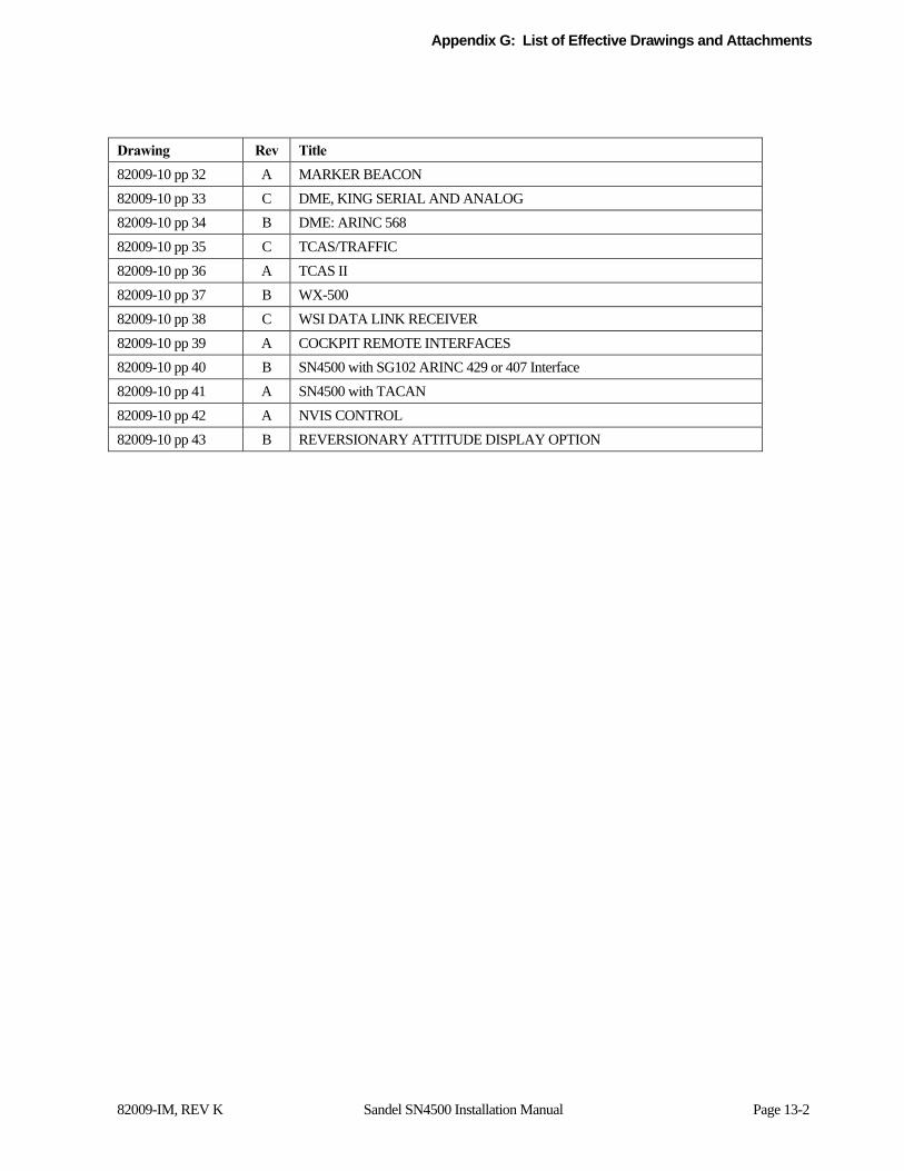
Appendix G: List of Effective Drawings and Attachments
82009-IM, REV K Sandel SN4500 Installation Manual Page 13-2
Drawing Rev Title
82009-10 pp 32 A MARKER BEACON
82009-10 pp 33 C DME, KING SERIAL AND ANALOG
82009-10 pp 34 B DME: ARINC 568
82009-10 pp 35 C TCAS/TRAFFIC
82009-10 pp 36 A TCAS II
82009-10 pp 37 B WX-500
82009-10 pp 38 C WSI DATA LINK RECEIVER
82009-10 pp 39 A COCKPIT REMOTE INTERFACES
82009-10 pp 40 B SN4500 with SG102 ARINC 429 or 407 Interface
82009-10 pp 41 A SN4500 with TACAN
82009-10 pp 42 A NVIS CONTROL
82009-10 pp 43 B REVERSIONARY ATTITUDE DISPLAY OPTION
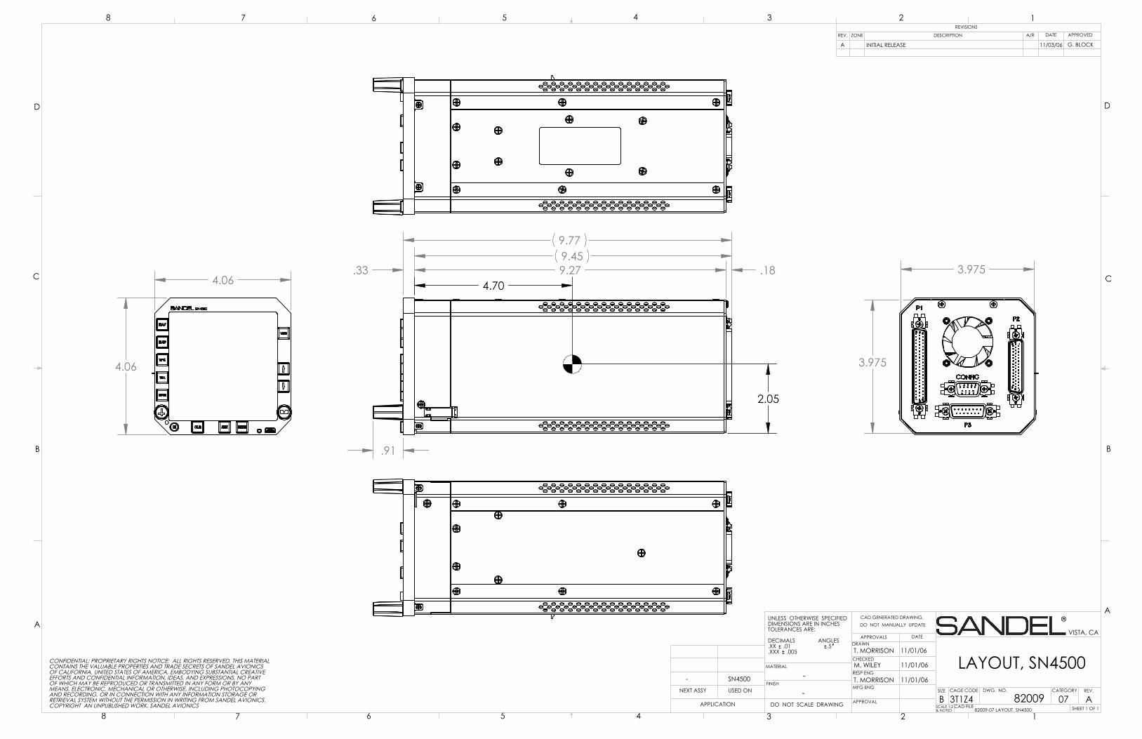
4.06
4.06
.33 9.27
.91
.189.459.77
4.70
2.05
3.975
3.975
D
C
B
AA
B
C
D
CAD GENERATED DRAWING,DO NOT MANUALLY UPDATE
SCALE 1:2& NOTED
SIZE CAGE CODE
BSHEET 1 OF 1
REV.
LAYOUT, SN4500
DATEAPPROVALSDRAWN
CHECKED
RESP ENG
MFG ENG
APPROVAL
UNLESS OTHERWISE SPECIFIEDDIMENSIONS ARE IN INCHESTOLERANCES ARE:
DECIMALS ANGLES.XX .01 .5.XXX .005
MATERIAL
FINISH-
DO NOT SCALE DRAWINGAPPLICATION
USED ONNEXT ASSY
12345678
8 7 6 5 4 3 2 1REVISIONS
REV. DESCRIPTION APPROVED
VISTA, CA
A82009
T. MORRISON
DWG. NO.
3T1Z4
G
G
-
M. WILEY
T. MORRISON
11/01/06
11/01/06
11/01/06
82009-07 LAYOUT, SN4500
CONFIDENTIAL: PROPRIETARY RIGHTS NOTICE: ALL RIGHTS RESERVED. THIS MATERIALCONTAINS THE VALUABLE PROPERTIES AND TRADE SECRETS OF SANDEL AVIONICSOF CALIFORNIA, UNITED STATES OF AMERICA, EMBODYING SUBSTANTIAL CREATIVEEFFORTS AND CONFIDENTIAL INFORMATION, IDEAS, AND EXPRESSIONS, NO PARTOF WHICH MAY BE REPRODUCED OR TRANSMITTED IN ANY FORM OR BY ANYMEANS, ELECTRONIC, MECHANICAL OR OTHERWISE, INCLUDING PHOTOCOPYINGAND RECORDING, OR IN CONNECTION WITH ANY INFORMATION STORAGE ORRETRIEVAL SYSTEM WITHOUT THE PERMISSION IN WRITING FROM SANDEL AVIONICS.COPYRIGHT AN UNPUBLISHED WORK. SANDEL AVIONICS CAD FILE
-
INITIAL RELEASEA
ZONE
SN4500
11/03/06 G. BLOCK
CATEGORY
07
DATEA/R
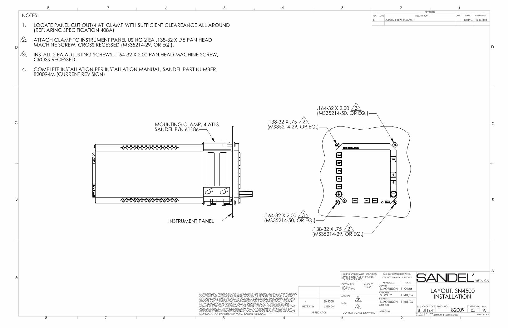
.164-32 X 2.00 3(MS35214-50, OR EQ.)
.138-32 X .75 2(MS35214-29, OR EQ.)
.138-32 X .75 2(MS35214-29, OR EQ.)
.164-32 X 2.00 3(MS35214-50, OR EQ.)
INSTRUMENT PANEL
MOUNTING CLAMP, 4 ATI-SSANDEL P/N 61186
D
C
B
AA
B
C
D
CAD GENERATED DRAWING,DO NOT MANUALLY UPDATE
SCALE 1:2& NOTED
SIZE CAGE CODE
BSHEET 1 OF 2
REV.
LAYOUT, SN4500INSTALLATION
DATEAPPROVALSDRAWN
CHECKED
RESP ENG
MFG ENG
APPROVAL
UNLESS OTHERWISE SPECIFIEDDIMENSIONS ARE IN INCHESTOLERANCES ARE:
DECIMALS ANGLES.XX .01 .5.XXX .005
MATERIAL
FINISH3
DO NOT SCALE DRAWINGAPPLICATION
USED ONNEXT ASSY
12345678
8 7 6 5 4 3 2 1REVISIONS
REV. DESCRIPTION APPROVED
VISTA, CA
A82009
T. MORRISON
DWG. NO.
3T1Z44
NOTES:
LOCATE PANEL CUT OUT/4 ATI CLAMP WITH SUFFICIENT CLEAREANCE ALL AROUND1.(REF. ARINC SPECIFICATION 408A)
ATTACH CLAMP TO INSTRUMENT PANEL USING 2 EA .138-32 X .75 PAN HEAD 2.MACHINE SCREW, CROSS RECESSED (MS35214-29, OR EQ.).
INSTALL 2 EA ADJUSTING SCREWS, .164-32 X 2.00 PAN HEAD MACHINE SCREW, 3.CROSS RECESSED.
COMPLETE INSTALLATION PER INSTALLATION MANUAL, SANDEL PART NUMBER4.82009-IM (CURRENT REVISION)
M. WILEY
T. MORRISON
11/01/06
11/01/06
11/01/06
82009-05 SN4500 INSTALL
CONFIDENTIAL: PROPRIETARY RIGHTS NOTICE: ALL RIGHTS RESERVED. THIS MATERIALCONTAINS THE VALUABLE PROPERTIES AND TRADE SECRETS OF SANDEL AVIONICSOF CALIFORNIA, UNITED STATES OF AMERICA, EMBODYING SUBSTANTIAL CREATIVEEFFORTS AND CONFIDENTIAL INFORMATION, IDEAS, AND EXPRESSIONS, NO PARTOF WHICH MAY BE REPRODUCED OR TRANSMITTED IN ANY FORM OR BY ANYMEANS, ELECTRONIC, MECHANICAL OR OTHERWISE, INCLUDING PHOTOCOPYINGAND RECORDING, OR IN CONNECTION WITH ANY INFORMATION STORAGE ORRETRIEVAL SYSTEM WITHOUT THE PERMISSION IN WRITING FROM SANDEL AVIONICS.COPYRIGHT AN UNPUBLISHED WORK. SANDEL AVIONICS CAD FILE
-
A/R 814 INITIAL RELEASEB
ZONE
SN4500
11/03/06 G. BLOCK
CATEGORY
05
DATEA/R
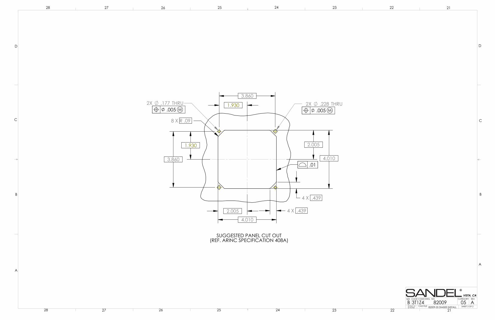
4.010
3.860
3.860
8 X R .09
4.010
2X .228 THRU2X .177 THRU
2.005
1.930
1.930 2.005
4 X .439
4 X .439
SUGGESTED PANEL CUT OUT(REF. ARINC SPECIFICATION 408A)
.005 M
.01
.005 M
D
C
B
AA
B
C
D
SCALE 1:2& NOTED
SIZE CAGE CODE
BREV.
2122232425262728
28 27 26 25 24 23 22 21
VISTA, CA
82009 ADWG. NO.
3T1Z4SHEET 2 OF 2CAD FILE: 82009-05 SN4500 INSTALL05
CATEGORY
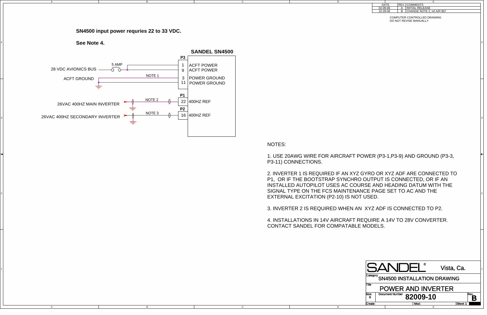
A
A
B
B
C
C
D
D
E
E
4 4
3 3
2 2
1 1
26VAC 400HZ MAIN INVERTER
26VAC 400HZ SECONDARY INVERTER
Title
Size Document Number Rev
Create: Sheet of
Category
Mod:B
POWER AND INVERTER
Vista, Ca.
B
1 29
SN4500 INSTALLATION DRAWINGTitle
Size Document Number Rev
Create: Sheet of
Category
Mod:B
POWER AND INVERTER
Vista, Ca.
B
1 29
SN4500 INSTALLATION DRAWINGTitle
Size Document Number Rev
Create: Sheet of
Category
Mod:B
POWER AND INVERTER
Vista, Ca.
B
1 29
SN4500 INSTALLATION DRAWING
P3
22 400HZ REF
NOTE 1
19
5 AMP28 VDC AVIONICS BUS
ACFT GROUND 311
ACFT POWERACFT POWER
POWER GROUNDPOWER GROUND
P1
COMMENTSDATEINITIAL RELEASEA
REV
SANDEL SN4500
82009-10
16 400HZ REF
P2
NOTE 2
NOTE 3
NOTES:
1. USE 20AWG WIRE FOR AIRCRAFT POWER (P3-1,P3-9) AND GROUND (P3-3,P3-11) CONNECTIONS.
2. INVERTER 1 IS REQUIRED IF AN XYZ GYRO OR XYZ ADF ARE CONNECTED TOP1, OR IF THE BOOTSTRAP SYNCHRO OUTPUT IS CONNECTED, OR IF ANINSTALLED AUTOPILOT USES AC COURSE AND HEADING DATUM WITH THESIGNAL TYPE ON THE FCS MAINTENANCE PAGE SET TO AC AND THEEXTERNAL EXCITATION (P2-10) IS NOT USED.
3. INVERTER 2 IS REQUIRED WHEN AN XYZ ADF IS CONNECTED TO P2.
4. INSTALLATIONS IN 14V AIRCRAFT REQUIRE A 14V TO 28V CONVERTER. CONTACT SANDEL FOR COMPATABLE MODELS.
COMPUTER CONTROLLED DRAWINGDO NOT REVISE MANUALLY
SN4500 input power requries 22 to 33 VDC.
See Note 4.
B CHANGE NOTE 2, ref A/R 86702-09-0610-28-06
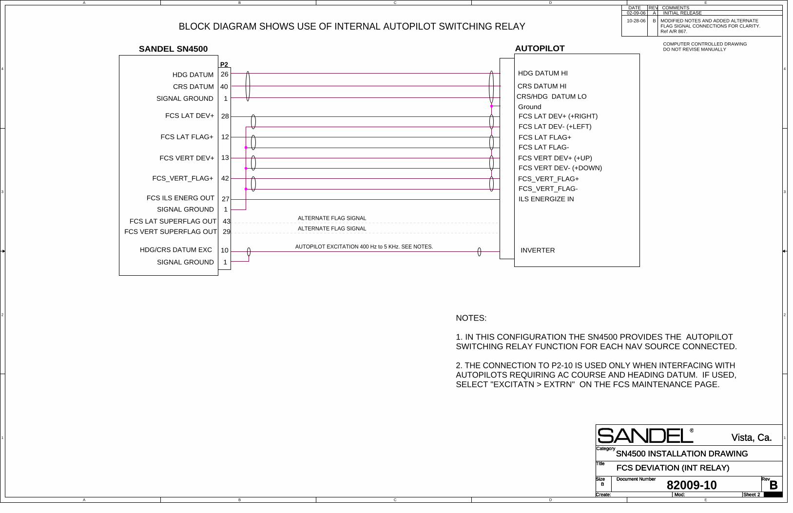
A
A
B
B
C
C
D
D
E
E
4 4
3 3
2 2
1 1
Title
Size Document Number Rev
Create: Sheet of
Category
Mod:
B
FCS DEVIATION (INT RELAY)
Vista, Ca.
B
2 29
SN4500 INSTALLATION DRAWINGTitle
Size Document Number Rev
Create: Sheet of
Category
Mod:
B
FCS DEVIATION (INT RELAY)
Vista, Ca.
B
2 29
SN4500 INSTALLATION DRAWINGTitle
Size Document Number Rev
Create: Sheet of
Category
Mod:
B
FCS DEVIATION (INT RELAY)
Vista, Ca.
B
2 29
SN4500 INSTALLATION DRAWING
AUTOPILOT
CRS/HDG DATUM LO
SANDEL SN4500
SIGNAL GROUND
40
26
Ground1
P2HDG DATUM HI
CRS DATUM HI
28
FCS LAT FLAG+ 12
13FCS VERT DEV+
42FCS_VERT_FLAG+
FCS ILS ENERG OUT 27
1SIGNAL GROUND
FCS LAT DEV+
FCS VERT DEV+ (+UP)
FCS_VERT_FLAG+
ILS ENERGIZE IN
FCS LAT DEV+ (+RIGHT)
82009-10
FCS LAT DEV- (+LEFT)
FCS LAT FLAG+
FCS LAT FLAG-
FCS VERT DEV- (+DOWN)
FCS_VERT_FLAG-
COMMENTSDATEINITIAL RELEASEA
REV
COMPUTER CONTROLLED DRAWINGDO NOT REVISE MANUALLY
CRS DATUM
HDG DATUM
BLOCK DIAGRAM SHOWS USE OF INTERNAL AUTOPILOT SWITCHING RELAY
NOTES:
1. IN THIS CONFIGURATION THE SN4500 PROVIDES THE AUTOPILOTSWITCHING RELAY FUNCTION FOR EACH NAV SOURCE CONNECTED.
2. THE CONNECTION TO P2-10 IS USED ONLY WHEN INTERFACING WITHAUTOPILOTS REQUIRING AC COURSE AND HEADING DATUM. IF USED,SELECT "EXCITATN > EXTRN" ON THE FCS MAINTENANCE PAGE.
HDG/CRS DATUM EXC 10
1SIGNAL GROUND
INVERTERAUTOPILOT EXCITATION 400 Hz to 5 KHz. SEE NOTES.
43
29
FCS LAT SUPERFLAG OUT
FCS VERT SUPERFLAG OUT
ALTERNATE FLAG SIGNAL
ALTERNATE FLAG SIGNAL
B MODIFIED NOTES AND ADDED ALTERNATEFLAG SIGNAL CONNECTIONS FOR CLARITY.Ref A/R 867.
02-09-06
10-28-06
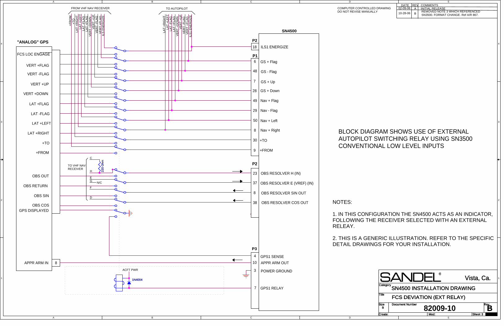
A
A
B
B
C
C
D
D
E
E
4 4
3 3
2 2
1 1
Title
Size Document Number Rev
Create: Sheet of
Category
Mod:
B
FCS DEVIATION (EXT RELAY)
Vista, Ca.
B
3 29
SN4500 INSTALLATION DRAWINGTitle
Size Document Number Rev
Create: Sheet of
Category
Mod:
B
FCS DEVIATION (EXT RELAY)
Vista, Ca.
B
3 29
SN4500 INSTALLATION DRAWINGTitle
Size Document Number Rev
Create: Sheet of
Category
Mod:
B
FCS DEVIATION (EXT RELAY)
Vista, Ca.
B
3 29
SN4500 INSTALLATION DRAWING
"ANALOG" GPS
VERT +FLAG
VERT -FLAG
VERT +UP
VERT +DOWN
LAT +FLAG
LAT -FLAG
LAT +RIGHT
LAT +LEFT
+FROM
+TO
F
H
D
E
TO VHF NAVRECEIVER
OBS OUT
OBS RETURN
OBS COS
OBS SIN
GPS DISPLAYED
6
OBS RESOLVER H (IN)
9
18
8
SN4500
23
28
8
+TO
OBS RESOLVER E (VREF) (IN)
49
OBS RESOLVER COS OUT
7
50
37
30
ILS1 ENERGIZE
38
29
+FROM
48
OBS RESOLVER SIN OUT
P2
P3
APPR ARM IN 8 10 APPR ARM OUT
GN/C
LA
T +
RIG
HT
LA
T +
LE
FT
LA
T -
FLA
GLA
T +
FLA
GV
ER
T +
DO
WN
VE
RT
+U
PV
ER
T -
FLA
GV
ER
T +
FLA
GIL
S1 E
NE
RG
IZE
TO AUTOPILOT
C
GPS1 SENSE
LA
T +
FLA
G
LA
T +
LE
FT
VE
RT
+F
LA
GIL
S E
NE
RG
IZE
VE
RT
-F
LA
G
+T
OLA
T +
RIG
HT
VE
RT
+D
OW
N
+F
RO
M
LA
T -
FLA
G
FROM VHF NAV RECEIVER
VE
RT
+U
P
FCS LOC ENGAGE
Nav + Right
Nav + Left
Nav + Flag
Nav - Flag
GS - Flag
GS + Flag
GS + Up
GS + Down
P1
P2
4
GPS1 RELAY
ACFT PWR
7
POWER GROUND3
BLOCK DIAGRAM SHOWS USE OF EXTERNALAUTOPILOT SWITCHING RELAY USING SN3500CONVENTIONAL LOW LEVEL INPUTS
82009-10
COMMENTSDATEINITIAL RELEASEA
REVCOMPUTER CONTROLLED DRAWINGDO NOT REVISE MANUALLY
NOTES:
1. IN THIS CONFIGURATION THE SN4500 ACTS AS AN INDICATOR,FOLLOWING THE RECEIVER SELECTED WITH AN EXTERNALRELEAY.
2. THIS IS A GENERIC ILLUSTRATION. REFER TO THE SPECIFICDETAIL DRAWINGS FOR YOUR INSTALLATION.
BREMOVED NOTE 3 WHICH REFERENCEDSN3500. FORMAT CHANGE. Ref A/R 867.
02-09-06
10-28-06
1N40041N4004
22
0 O
hm
22
0 O
hm

A
A
B
B
C
C
D
D
E
E
4 4
3 3
2 2
1 1
Title
Size Document Number Rev
Create: Sheet of
Category
Mod:B
FCS GENERIC CRS/HDG DATUM
Vista, Ca.
B
4 29
SN4500 INSTALLATION DRAWINGTitle
Size Document Number Rev
Create: Sheet of
Category
Mod:B
FCS GENERIC CRS/HDG DATUM
Vista, Ca.
B
4 29
SN4500 INSTALLATION DRAWINGTitle
Size Document Number Rev
Create: Sheet of
Category
Mod:B
FCS GENERIC CRS/HDG DATUM
Vista, Ca.
B
4 29
SN4500 INSTALLATION DRAWING
4. WHEN BC OUTPUT NOT REQUIRED LEAVE UNCONNECTED.
5. BC OUTPUT IS AN OPEN COLLECTOR. RELAY REQUIRED IF BACKCOURSE INPUT TO AUTOPILOT REQUIRES +28V TO ACTIVATE. OTHERWISE CONNECT SN4500 BC OUTPUT DIRECTLY TO AUTOPILOTBC INPUT.
COMMENTSDATEINITIAL RELEASEA
REV
6. IF CRS/HDG WORK BACKWARDS, CHANGE LEFT/RIGHT DATUM SETTING ONFCS EMULATION MAINTENANCE PAGE.
COMPUTER CONTROLLED DRAWINGDO NOT REVISE MANUALLY
NOTES:
1. IF INSTALLATION ALREADY CONTAINS A KING KA52/57 AUTOPILOTADAPTER IT MAY REMAIN IN THE SYSTEM. TREAT THE SN4500 AS AKI525.
2. SN4500 DATUM OUTPUTS ARE REFERENCED TO SIGNAL GROUND.
3. CHECK AUTOPILOT INTERNAL SCHEMATIC TO INSURE THAT THE SN4500 ISDRIVING THE SIGNAL INPUTS AND THAT IT IS PERMISSABLE TO GROUND 'C'OR 'Y' AS SHOWN. IN SOME CASES 'C' MAY BE SIGNAL AND 'H' MAY BEGROUND. CALL FACTORY WITH ANY QUESTIONS.
82009-10
AUTOPILOT
SIGNAL GROUND 1
26
SANDEL SN4500
CRS/HDG DATUM LO
P2
CRS DATUM 40
HDG DATUM
CRS DATUM HI
Ground
SEE NOTE 1 CONCERNINGKING KA52/57
DC CRS/HDG DATUM TYPICALINTERCONNECT
CRS DATUM
SANDEL SN4500
CRS DATUM X OR H
HDG DATUM X OR H
INVERTER
AUTOPILOT
Note 3
P2
P2
HDG DATUM
HDG/CRS DATUM EXC
SIGNAL GROUND
26
SIGNAL GROUND
10
40
1
1
HDG DATUM HI
HDG DATUM Y OR C
CRS DATUM Y OR C
ACFT PWR
ACFT PWR
NOTE 5
BACK COURSE 14
BACK COURSE
P3
AC AUTOPILOT TYPICAL INTERCONNECT
Note 4
Optional
AUTOPILOT EXCITATION 400 Hz to 5 KHz.
B NOTE CORRECTION (SPELLING). Ref A/R 867.02-09-0610-28-06
1N40041N4004
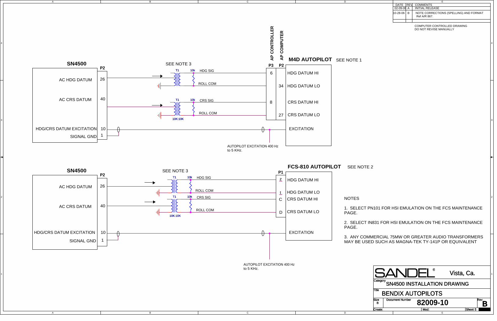
A
A
B
B
C
C
D
D
E
E
4 4
3 3
2 2
1 1
Title
Size Document Number Rev
Create: Sheet of
Category
Mod:B
BENDIX AUTOPILOTS
Vista, Ca.
B
5 29
SN4500 INSTALLATION DRAWINGTitle
Size Document Number Rev
Create: Sheet of
Category
Mod:B
BENDIX AUTOPILOTS
Vista, Ca.
B
5 29
SN4500 INSTALLATION DRAWINGTitle
Size Document Number Rev
Create: Sheet of
Category
Mod:B
BENDIX AUTOPILOTS
Vista, Ca.
B
5 29
SN4500 INSTALLATION DRAWING
A INITIAL RELEASEDATE REV COMMENTS
NOTES
1. SELECT PN101 FOR HSI EMULATION ON THE FCS MAINTENANCEPAGE.
2. SELECT IN831 FOR HSI EMULATION ON THE FCS MAINTENANCEPAGE.
3. ANY COMMERCIAL 75MW OR GREATER AUDIO TRANSFORMERSMAY BE USED SUCH AS MAGNA-TEK TY-141P OR EQUIVALENT
ROLL COM
ROLL COM
HDG SIG
CRS SIG
HDG DATUM LO
HDG DATUM HI
CRS DATUM HI
CRS DATUM LO
M4D AUTOPILOTAP
CO
NT
RO
LL
ER
AP
CO
MP
UT
ER
6
8
27
P2
34
P3
AC HDG DATUM 26
SN4500P2
AC CRS DATUM 40
ROLL COM
ROLL COM
HDG SIG
CRS SIGHDG DATUM LO
HDG DATUM HI
CRS DATUM HI
CRS DATUM LO
C
D
z
t
FCS-810 AUTOPILOTP1
SEE NOTE 1SEE NOTE 3
SEE NOTE 3SEE NOTE 2
82009-10
EXCITATION
EXCITATION
HDG/CRS DATUM EXCITATION 10
AUTOPILOT EXCITATION 400 Hzto 5 KHz.
1SIGNAL GND
AC HDG DATUM 26
SN4500P2
AC CRS DATUM 40
HDG/CRS DATUM EXCITATION 10
1SIGNAL GND
COMPUTER CONTROLLED DRAWINGDO NOT REVISE MANUALLY
B NOTE CORRECTIONS (SPELLING) AND FORMAT Ref A/R 867.
02-09-06
10-28-06
AUTOPILOT EXCITATION 400 Hzto 5 KHz.
10k10kT1T1
T1
10K:10K
T1
10K:10K
10k10k
T1
10K:10K
T1
10K:10K
T1T1
10k10k
10k10k

A
A
B
B
C
C
D
D
E
E
4 4
3 3
2 2
1 1
Title
Size Document Number Rev
Create: Sheet of
Category
Mod:B
BENDIX/KING AUTOPILOTS
Vista, Ca.
B
6 29
SN4500 INSTALLATION DRAWINGTitle
Size Document Number Rev
Create: Sheet of
Category
Mod:B
BENDIX/KING AUTOPILOTS
Vista, Ca.
B
6 29
SN4500 INSTALLATION DRAWINGTitle
Size Document Number Rev
Create: Sheet of
Category
Mod:B
BENDIX/KING AUTOPILOTS
Vista, Ca.
B
6 29
SN4500 INSTALLATION DRAWING
SN4500
40
CRS/HDG DATUM LO
26
1
HDG DATUM HI
P2
CRS DATUM HI
KAP 140
SIGNAL GND
17
2
27
P140137 PIN
DC CRS DATUM
DC HDG DATUM
P140250 PIN
HONEYWELL
KFC 200
KFC 150SN4500
40
1
DC HDG SIG
P2
DC CRS SIG
SIGNAL GND
DC CRS DATUM
26DC HDG DATUM
CRS DATUM LO
KC 295
H
P2952SN4500
40
1
DC HDG SIG
P2
DC CRS SIG
SIGNAL GND
W
M
DC CRS DATUM
26DC HDG DATUM
HDG/CRSDATUM LO
KFC 225
X
W
19
P1901
SN4500
40
CRS/HDG DATUM LO
26
1
HDG DATUM HI
P2
CRS DATUM HI
SIGNAL GND
16
2
28
DC CRS DATUM
DC HDG DATUM
J2252
J2251
COMMENTSDATE REVA
NOTES:
1. SELECT "KI525" FOR HSI EMULATION ON THE FCS MAINTENANCE PAGE.
2. SELECT "PN101" FOR HSI EMULATION ON THE FCS MAINTENANCE PAGE.
HDG VALID 11(AS AVAILABLE FROM GYRO)
HDG VALID 11(AS AVAILABLE FROM GYRO)
KC190/KC191/KC192
INITIAL RELEASE
HDG DATUM LO20
82009-10
SN4500
40
BACK COURSE
BACK COURSE +
14
P2
AC CRS DATUM
SIGNAL GND
HDG DATUM H
HDG DATUM C
ACFTPWR
13
12
16
17
KFC 300
SEE NOTE 2.
26AC HDG DATUM
CRS DATUM H
CRS DATUM C
14
15
BACK COURSE -
KCP 320J1
P3
P2
10
1
AUTOPILOT EXITATION 400 Hzto 5 KHz.
CRS/HDG DATUM EXCITATION INVERTER
COMPUTER CONTROLLED DRAWINGDO NOT REVISE MANUALLY
B ADDED NOTE 2. Ref A/R 867.02-09-06
10-28-06
2 meg 1/4 watt2 meg 1/4 watt
1N40041N4004

A
A
B
B
C
C
D
D
E
E
4 4
3 3
2 2
1 1
Title
Size Document Number Rev
Create: Sheet of
Category
Mod:
ACENTURY IV AUTOPILOTS
Vista, Ca.
B
7 29
SN4500 INSTALLATION DRAWINGTitle
Size Document Number Rev
Create: Sheet of
Category
Mod:
ACENTURY IV AUTOPILOTS
Vista, Ca.
B
7 29
SN4500 INSTALLATION DRAWINGTitle
Size Document Number Rev
Create: Sheet of
Category
Mod:
ACENTURY IV AUTOPILOTS
Vista, Ca.
B
7 29
SN4500 INSTALLATION DRAWING
COMMENTSDATE REVA INITIAL RELEASE
COMPUTER CONTROLLED DRAWINGDO NOT REVISE MANUALLY
82009-10
CRS DATUM 40
SN4500
CRS/HDG DATUMEXCITATION
CENTURY IV INTERCONNECT (5KHZ AC VERSION)
HDG DATUM
P2
26 HDG DATUM
CRS DATUM
NOTES 1 & 2
CRS DATUM 40
SN4500
CENTURY IV INTERCONNECT (DC VERSION)
HDG DATUM
P2
26 HDG DATUM
CRS DATUM
P2
10
5KhzEXCITATIONFROMCENTURYIV
2. ON FCS-EMULATION MAINTENANC PAGE, ADJUST HDG-GRADIENT (ANDCRS-GRADIENT IF USED) TO HIGHEST VALUE THAT DOES NOT OVER-SHOOTTHE LUBBER LINE DURING HDG-MODE AND NAV-MODE COURSE CHANGESRESPECTIVELY. EXCEPT FOR KI-525 THESE VALUES WILL BE IDENTICAL.
1. SELECT NSD-360DC ON FCS EMULATION MAINTENANCE PAGE.
NOTES:
NOTES 1 & 2
02-09-06
0.1 uF 50v min0.1 uF 50v min
0.1 uF 50v min0.1 uF 50v min

A
A
B
B
C
C
D
D
E
E
4 4
3 3
2 2
1 1
Title
Size Document Number Rev
Create: Sheet of
Category
Mod:
ACENTURY 1C388 COUPLERS
Vista, Ca.
B
8 29
SN4500 INSTALLATION DRAWINGTitle
Size Document Number Rev
Create: Sheet of
Category
Mod:
ACENTURY 1C388 COUPLERS
Vista, Ca.
B
8 29
SN4500 INSTALLATION DRAWINGTitle
Size Document Number Rev
Create: Sheet of
Category
Mod:
ACENTURY 1C388 COUPLERS
Vista, Ca.
B
8 29
SN4500 INSTALLATION DRAWING
COMMENTSDATE REV
SN4500
(5Khz)
26
40
P2CRS/HDGDATUMEXCITATION
HDG DATUM
CRS DATUM
CENTURY 1C-388 & 1C388-M RADIO COUPLERS
10
CD33 TO AMP
C
1. SELECT NSD-360DC ON THE FCS MENU.
CD33 TO DG
F
D
E
SN4500
(5Khz)
26
40
P2
HDG DATUM
CRS DATUM
CENTURY 1C-388-C, 1C388-MC RADIO COUPLERS
10D
CD33 TO DG
E
n/c
B ROLL COM
HDG SIG
HDG DATUM
P2
26
E
D 10
CRS DATUM40
SN4500CD33 TO DG
CENTURY 1C-388-2 RADIO COUPLER
n/c
ROLL EXC
ROLL EXC
ROLL EXC
ROLL EXC
A
A
B
HDG SIG
ROLL COM
AHDG SIG
ROLL EXC
ROLL EXC(5Khz)
CRS SIGB
CD33 TO AMP
B ROLL COM
CENTURY 1C-388-3 RADIO COUPLER
10
P2SN4500
26 HDG DATUM
CD33 TO DG
40
E
CRS DATUM
D
A HDG SIG
ROLL EXC
ROLL EXC
(5Khz)
CRS SIGB
ROLL COM
F
C
ROLL COM
(ABOVE COUPLERS DO NOTSUPPORT COURSE DATUM.)
NOTES:
2. ON FCS EMULATION MAINTENANCE PAGE, ADJUST HDG-GRADIENT (ANDCRS-GRADIENT IF USED) TO HIGHEST VALUE THAT DOES NOT OVER-SHOOTTHE LUBBER LINE DURING HDG-MODE AND NAV-MODE COURSE CHANGESRESPECTIVELY. NORMALLY THESE VALUES WILL BE THE SAME.
3. GROUND CONNECTIONS TO SN4500 SIGNAL GROUND.
4. DO NOT GROUND ANY CENTURY II/III SIGNALS EVEN DURINGTROUBLESHOOTING. THIS COULD DAMAGE THE AUTOPILOT. SEE THECENTURY INSTALLATION MANUAL FOR DETAILS.
A INITIAL RELEASE
5. ANY COMMERCIAL 75MW OR GREATER AUDIO TRANSFORMERSMAY BE USED. MAGNA-TEK TY-141P OR EQUIVALENT.
COMPUTER CONTROLLED DRAWING
PARALLELWITHEXISTINGWIRES
JW Miller PN:9250-276 or Equiv
DO NOT REVISE MANUALLY
82009-10
02-09-06
CRS/HDGDATUMEXCITATION
CRS/HDGDATUMEXCITATION
CRS/HDGDATUMEXCITATION
10k10k
T1
10K:10K
T1
10K:10K
T1
10K:10K
T1
10K:10K
10k10k
10k10k
10k10k
T1
10K:10K
T1
10K:10K
T1
10K:10K
T1
10K:10KT1
10K:10K
T1
10K:10K
T1
10K:10K
T1
10K:10K
T1
10K:10K
T1
10K:10KT1
10K:10K
T1
10K:10K
10k10k
T1
10K:10K
T1
10K:10K
10k10k
27mH27mH
.027uF.027uF
10k10k
10k10k
T1
10K:10K
T1
10K:10K
10k10k
10k10k
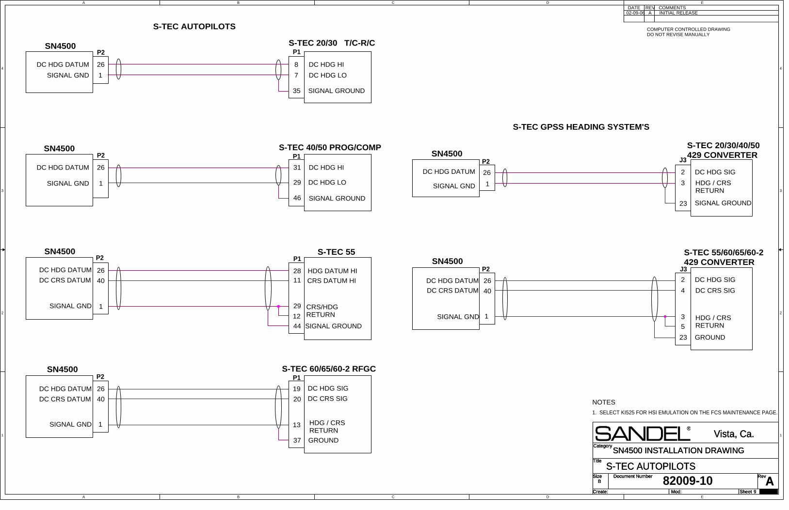
A
A
B
B
C
C
D
D
E
E
4 4
3 3
2 2
1 1
Title
Size Document Number Rev
Create: Sheet of
Category
Mod:
AS-TEC AUTOPILOTS
Vista, Ca.
B
9 29
SN4500 INSTALLATION DRAWINGTitle
Size Document Number Rev
Create: Sheet of
Category
Mod:
AS-TEC AUTOPILOTS
Vista, Ca.
B
9 29
SN4500 INSTALLATION DRAWINGTitle
Size Document Number Rev
Create: Sheet of
Category
Mod:
AS-TEC AUTOPILOTS
Vista, Ca.
B
9 29
SN4500 INSTALLATION DRAWING
SN4500
40
CRS/HDG RETURN
1
HDG DATUM HI
P2
CRS DATUM HI
SIGNAL GND
2811
29
DC CRS DATUM
P1S-TEC 55
26DC HDG DATUM
12
SIGNAL GROUND
SN4500
40
1
DC HDG SIG
P2
DC CRS SIG
SIGNAL GND
19
20
13
DC CRS DATUM
P1S-TEC 60/65/60-2 RFGC
26DC HDG DATUM
HDG / CRSRETURN
37 GROUND
44
26 DC HDG SIG
4
J3P2
2
SIGNAL GND
DC HDG DATUM
3
SN4500
1
DC CRS SIG40DC CRS DATUM
23 GROUND
S-TEC 55/60/65/60-2429 CONVERTER
5HDG / CRSRETURN
SN4500
1
P2
SIGNAL GND
31
29
P1S-TEC 40/50 PROG/COMP
26DC HDG DATUM
SIGNAL GROUND46
DC HDG HI
DC HDG LO
DC HDG DATUM 8
1
P1
SIGNAL GND
26
SIGNAL GROUND
DC HDG LO
35
S-TEC 20/30 T/C-R/CP2
SN4500
DC HDG HI
7
SIGNAL GND
P2
226
SIGNAL GROUND
1 3
SN4500J3
DC HDG DATUM
23
DC HDG SIG
S-TEC 20/30/40/50429 CONVERTER
HDG / CRSRETURN
A INITIAL RELEASEDATE REV COMMENTS
COMPUTER CONTROLLED DRAWINGDO NOT REVISE MANUALLY
1. SELECT KI525 FOR HSI EMULATION ON THE FCS MAINTENANCE PAGE.
NOTES
S-TEC AUTOPILOTS
S-TEC GPSS HEADING SYSTEM'S
82009-10
02-09-06

A
A
B
B
C
C
D
D
E
E
4 4
3 3
2 2
1 1
Title
Size Document Number Rev
Create: Sheet of
Category
Mod:
BKING KG102A - SN4500 SLAVING
Vista, Ca.
B
10 29
SN4500 INSTALLATION DRAWINGTitle
Size Document Number Rev
Create: Sheet of
Category
Mod:
BKING KG102A - SN4500 SLAVING
Vista, Ca.
B
10 29
SN4500 INSTALLATION DRAWINGTitle
Size Document Number Rev
Create: Sheet of
Category
Mod:
BKING KG102A - SN4500 SLAVING
Vista, Ca.
B
10 29
SN4500 INSTALLATION DRAWING
A INITIAL RELEASEDATE REV COMMENTS
COMPUTER CONTROLLED DRAWINGDO NOT REVISE MANUALLY
82009-10
A
45
FLUXGATE X
GYRO VALID
L
9
25
Exc H
SANDEL SN4500
H
Y
KG102GYRO
j
MOTOR A
KMT112
AVIONICS BUS
PER MFG'SINSTALL MANUAL
E
MOTOR C
c
24
STEPPER A
t
3
Fluxgate X
FLUXGATE EXCITATION
POWER
STEPPER C
GYRO VALID1
FV DRIVEZ
GND
Fluxgate Y
FLUXGATE Z
GND
MAN CW
MAN CCW
25
a
GND
Fluxgate Z
AUTO
D
GROUND
FLUXGATE Y
B
P
39
P1
n
Exc CSIGNAL GROUND 1
P2
eb
Wv
SLAVING CT H
SLAVING CT C
B ADDED KG102 SLAVING CONNECTION. Ref A/R 867.02-09-06
10-28-06

A
A
B
B
C
C
D
D
E
E
4 4
3 3
2 2
1 1
Title
Size Document Number Rev
Create: Sheet of
Category
Mod:A
KCS55 - BOOSTRAP XYZ
Vista, Ca.
B
11 29
SN4500 INSTALLATION DRAWINGTitle
Size Document Number Rev
Create: Sheet of
Category
Mod:A
KCS55 - BOOSTRAP XYZ
Vista, Ca.
B
11 29
SN4500 INSTALLATION DRAWINGTitle
Size Document Number Rev
Create: Sheet of
Category
Mod:A
KCS55 - BOOSTRAP XYZ
Vista, Ca.
B
11 29
SN4500 INSTALLATION DRAWING
X
Y
EXCITATION
Z
3
SIGNAL GND
45
1
DG X
DG Y
P1SN4500
22
A/C 26VAC 400HZ LO
400HZ REF
GYRO VALID GYRO VALID25
GROUNDu
t
v
s
KI-525AP2
c
r
A/C 26VAC 400HZ HI
BENDIX/KING KI525A BOOTSTRAP MASTER WITH NO INTERNAL SN4500 SLAVING. (NOTES 1 AND 2)
P1
ADATE REV
INITIAL RELEASE
COMPUTER CONTROLLED DRAWINGDO NOT REVISE MANUALLY
COMMENTS
82009-10
SELECT NONE FOR FLUXGATETYPE.THIS CONFIGURATION IS USED WHEN BOOTSTRAPPED FROM ANEXISTING KCS55 SLAVED COMPASS SYSTEM. THIS MIGHT BE DESIRED WHERE AN EXISTING IS MOVED TO THE COPILOTS SIDE AND ANSN4500 IS INSTALLED ON THE PILOTS SIDE. UNDER THIS CONDITIONTHE SN4500 CAN BE DRIVEN BY THE BOOTSTRAP OUTPUT OF THECOPILOTS HSI.
1.
2.
02-09-06
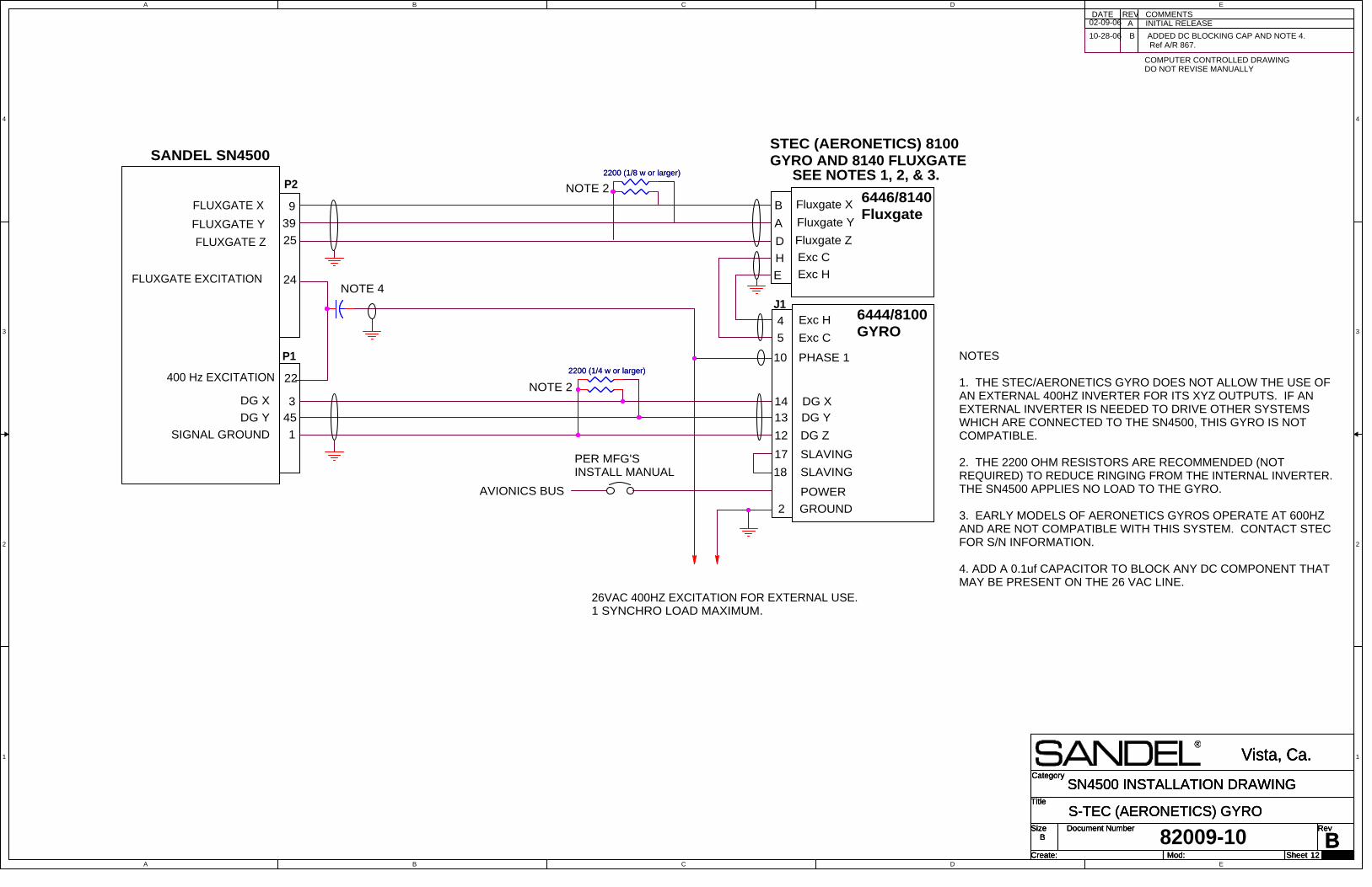
A
A
B
B
C
C
D
D
E
E
4 4
3 3
2 2
1 1
Title
Size Document Number Rev
Create: Sheet of
Category
Mod:B
S-TEC (AERONETICS) GYRO
Vista, Ca.
B
12 29
SN4500 INSTALLATION DRAWINGTitle
Size Document Number Rev
Create: Sheet of
Category
Mod:B
S-TEC (AERONETICS) GYRO
Vista, Ca.
B
12 29
SN4500 INSTALLATION DRAWINGTitle
Size Document Number Rev
Create: Sheet of
Category
Mod:B
S-TEC (AERONETICS) GYRO
Vista, Ca.
B
12 29
SN4500 INSTALLATION DRAWING
Exc C
24
DG Z
14
SANDEL SN4500
PHASE 1
5
SIGNAL GROUND
B
13
DG X
10
Fluxgate Y9
A
Fluxgate Z
1
DG Y
22
H
400 Hz EXCITATION
12
6444/8100 GYRO
E
45
GROUND
39
Exc H
DG X
AVIONICS BUS POWER
DG Y
P2
J1
3
4
D25
17
SLAVING
SLAVING
18
6446/8140 Fluxgate
A INITIAL RELEASEDATE REV COMMENTS
COMPUTER CONTROLLED DRAWINGDO NOT REVISE MANUALLY
FLUXGATE X
FLUXGATE Y
FLUXGATE Z
2
PER MFG'SINSTALL MANUAL
Fluxgate X
Exc H
Exc C
FLUXGATE EXCITATION
P1
82009-10
26VAC 400HZ EXCITATION FOR EXTERNAL USE. 1 SYNCHRO LOAD MAXIMUM.
STEC (AERONETICS) 8100GYRO AND 8140 FLUXGATE
NOTE 2
NOTE 2
NOTES
1. THE STEC/AERONETICS GYRO DOES NOT ALLOW THE USE OFAN EXTERNAL 400HZ INVERTER FOR ITS XYZ OUTPUTS. IF ANEXTERNAL INVERTER IS NEEDED TO DRIVE OTHER SYSTEMSWHICH ARE CONNECTED TO THE SN4500, THIS GYRO IS NOTCOMPATIBLE.
2. THE 2200 OHM RESISTORS ARE RECOMMENDED (NOTREQUIRED) TO REDUCE RINGING FROM THE INTERNAL INVERTER. THE SN4500 APPLIES NO LOAD TO THE GYRO.
3. EARLY MODELS OF AERONETICS GYROS OPERATE AT 600HZAND ARE NOT COMPATIBLE WITH THIS SYSTEM. CONTACT STECFOR S/N INFORMATION.
4. ADD A 0.1uf CAPACITOR TO BLOCK ANY DC COMPONENT THATMAY BE PRESENT ON THE 26 VAC LINE.
SEE NOTES 1, 2, & 3.
B ADDED DC BLOCKING CAP AND NOTE 4. Ref A/R 867.
NOTE 4
02-09-06
10-28-06
2200 (1/4 w or larger)2200 (1/4 w or larger)
2200 (1/8 w or larger)2200 (1/8 w or larger)
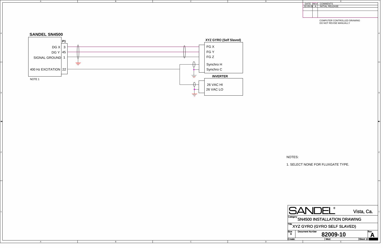
A
A
B
B
C
C
D
D
E
E
4 4
3 3
2 2
1 1
Title
Size Document Number Rev
Create: Sheet of
Category
Mod:A
XYZ GYRO (GYRO SELF SLAVED)
Vista, Ca.
B
13 29
SN4500 INSTALLATION DRAWINGTitle
Size Document Number Rev
Create: Sheet of
Category
Mod:A
XYZ GYRO (GYRO SELF SLAVED)
Vista, Ca.
B
13 29
SN4500 INSTALLATION DRAWINGTitle
Size Document Number Rev
Create: Sheet of
Category
Mod:A
XYZ GYRO (GYRO SELF SLAVED)
Vista, Ca.
B
13 29
SN4500 INSTALLATION DRAWING
SANDEL SN4500
45
3
FG Y
FG Z
FG XDG X
DG Y
26 VAC HI
Synchro H
Synchro C
INVERTER
XYZ GYRO (Self Slaved)
22400 Hz EXCITATION
26 VAC LO
P1
A INITIAL RELEASEDATE REV COMMENTS
COMPUTER CONTROLLED DRAWINGDO NOT REVISE MANUALLY
82009-10
1SIGNAL GROUND
NOTES:
1. SELECT NONE FOR FLUXGATE TYPE.
NOTE 1
02-09-06
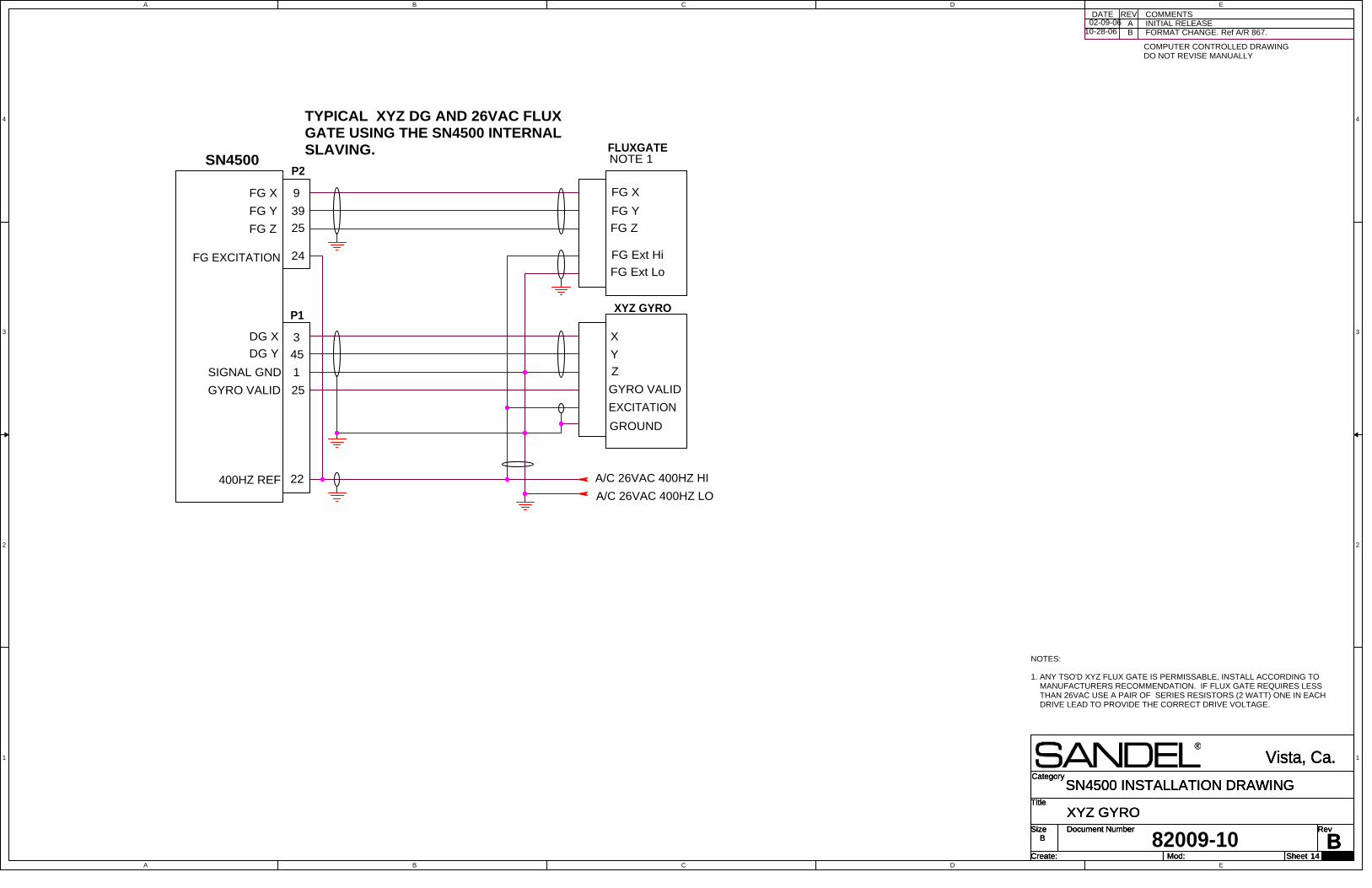
A
A
B
B
C
C
D
D
E
E
4 4
3 3
2 2
1 1
Title
Size Document Number Rev
Create: Sheet of
Category
Mod:B
XYZ GYRO
Vista, Ca.
B
14 29
SN4500 INSTALLATION DRAWINGTitle
Size Document Number Rev
Create: Sheet of
Category
Mod:B
XYZ GYRO
Vista, Ca.
B
14 29
SN4500 INSTALLATION DRAWINGTitle
Size Document Number Rev
Create: Sheet of
Category
Mod:B
XYZ GYRO
Vista, Ca.
B
14 29
SN4500 INSTALLATION DRAWING
A INITIAL RELEASEDATE REV COMMENTS
COMPUTER CONTROLLED DRAWINGDO NOT REVISE MANUALLY
82009-10
TYPICAL XYZ DG AND 26VAC FLUXGATE USING THE SN4500 INTERNALSLAVING.
X
Y
EXCITATION
Z
FG X
FG Z
FG Ext Hi
FG Ext Lo
FG Y
XYZ GYRO
FLUXGATE
3
SIGNAL GND
45
1
DG X
DG Y
9
39
25
FG Y
FG X
FG Z
P2SN4500
FG EXCITATION 24
NOTE 1
22
A/C 26VAC 400HZ LO400HZ REF A/C 26VAC 400HZ HI
P1
GYRO VALID GYRO VALID25
GROUND
ANY TSO'D XYZ FLUX GATE IS PERMISSABLE, INSTALL ACCORDING TOMANUFACTURERS RECOMMENDATION. IF FLUX GATE REQUIRES LESSTHAN 26VAC USE A PAIR OF SERIES RESISTORS (2 WATT) ONE IN EACHDRIVE LEAD TO PROVIDE THE CORRECT DRIVE VOLTAGE.
NOTES:
1.
B FORMAT CHANGE. Ref A/R 867.02-09-06
10-28-06
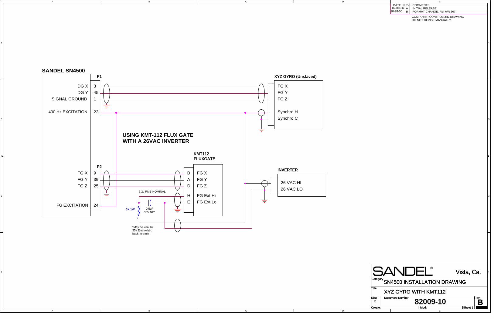
A
A
B
B
C
C
D
D
E
E
4 4
3 3
2 2
1 1
Title
Size Document Number Rev
Create: Sheet of
Category
Mod:B
XYZ GYRO WITH KMT112
Vista, Ca.
B
15 29
SN4500 INSTALLATION DRAWINGTitle
Size Document Number Rev
Create: Sheet of
Category
Mod:B
XYZ GYRO WITH KMT112
Vista, Ca.
B
15 29
SN4500 INSTALLATION DRAWINGTitle
Size Document Number Rev
Create: Sheet of
Category
Mod:B
XYZ GYRO WITH KMT112
Vista, Ca.
B
15 29
SN4500 INSTALLATION DRAWING
FG X
FG Z
FG Ext Hi
FG Ext Lo
FG Y
9
39
25
FG Y
FG X
FG Z
P2
FG EXCITATION 24
7.2v RMS NOMINAL
*May be 2ea 1uF35v Electrolyticback-to-back
D
A
H
B
E
KMT112FLUXGATE
0.5uF35V NP*
USING KMT-112 FLUX GATEWITH A 26VAC INVERTER
SANDEL SN4500
45
3
FG Y
FG XDG X
DG Y
26 VAC HI
Synchro C
INVERTER
XYZ GYRO (Unslaved)
22400 Hz EXCITATION
26 VAC LO
P1
1SIGNAL GROUND
A INITIAL RELEASEDATE REV COMMENTS
COMPUTER CONTROLLED DRAWINGDO NOT REVISE MANUALLY
82009-10
FG Z
Synchro H
B FORMAT CHANGE. Ref A/R 867.02-09-06
10-28-06
1K 1W 1K 1W

A
A
B
B
C
C
D
D
E
E
4 4
3 3
2 2
1 1
28 VDC IN FROM BUS
Title
Size Document Number Rev
Create: Sheet of
Category
Mod:
BCOLLINS PN101 UPGRADE
Vista, Ca.
B
16 29
SN4500 INSTALLATION DRAWINGTitle
Size Document Number Rev
Create: Sheet of
Category
Mod:
BCOLLINS PN101 UPGRADE
Vista, Ca.
B
16 29
SN4500 INSTALLATION DRAWINGTitle
Size Document Number Rev
Create: Sheet of
Category
Mod:
BCOLLINS PN101 UPGRADE
Vista, Ca.
B
16 29
SN4500 INSTALLATION DRAWING
ADATE REV COMMENTS
COMPUER CONTROLLED DRAWINGDO NOT REVISE MANUALLY
328A-3GSLAVING AMP
FG X
FG Z
FG Ext Hi
FG Ext Lo
FG Y
323A2GFLUXGATE
3
SIGNAL GND
45
1
DG X
DG Y
9
39
25
FG Y
FG X
FG Z
P2SN4500
FG EXCITATION 24
22400HZ REF
P1
GROUND
NOTE 5
E
D
B
C
A
19 GROUND
7
SERVO
SERVO
6
11
9
EXCITATION5NOTES
1. THIS CONFIGURATION DOES NOT ALLOW FOR AN ADDITIONALINVERTER DRIVING THE SN4500.
2. THIS CONFIGURATION DISABLES THE 328A-3G SLAVING ACTION.SLAVING IS PERFORMED INSIDE THE SN4500.
3. THE 328A-3G PROVIDES A HEADING FLAG OUTPUT TO THE SN4500.
4. THIS CONFIGURATION ALLOWS THE USE OF A COLLINS 332-E4 WITHOUT USING THE SLAVING FUNCTION OF THE 328A-3G SLAVINGACCESSORY.
5. THE 2200 OHM RESISTORS ARE RECOMMENDED (NOT REQUIRED) TOREDUCE RINGING FROM THE INTERNAL INVERTER. THE SN4500APPLIES NO LOAD TO THE GYRO.
6. YOU MUST REMOVE THE 323A-3G FLUX COMPENSATOR LOCATED ONTOP OF THE FLUX VALVE.
INITITAL RELEASE
LEAVING INSTALLED BUT BYPASSING THE SLAVING FUNCTION OFTHE COLLINS 328A-3G SLAVING ACCESSORY WHEN UPGRADING APN101 SYSTEM. SEE NOTES
82009-10
XOUT
ZOUT
EXT HI
EXT LO
YOUT
332E4 GYRO
D
E
A
B
C
26VAC ERECT
115V SPIN MTR
F
H
- FLAG OUTGYRO FLAG 25 16
GROUND
GYRO EXT HI
GYRO EXT LO
RETURN 115 VAC
ERECT 26 VAC
SPIN MTR 115V
28 VDC IN
1
20
21
29
30
17
2
SLAVING
NOTE 5
B FORMAT CHANGE. Ref A/R 867.02-09-06
10-28-06
2200 (1/4 w or larger)2200 (1/4 w or larger)
2200 (1/8 w or larger)2200 (1/8 w or larger)
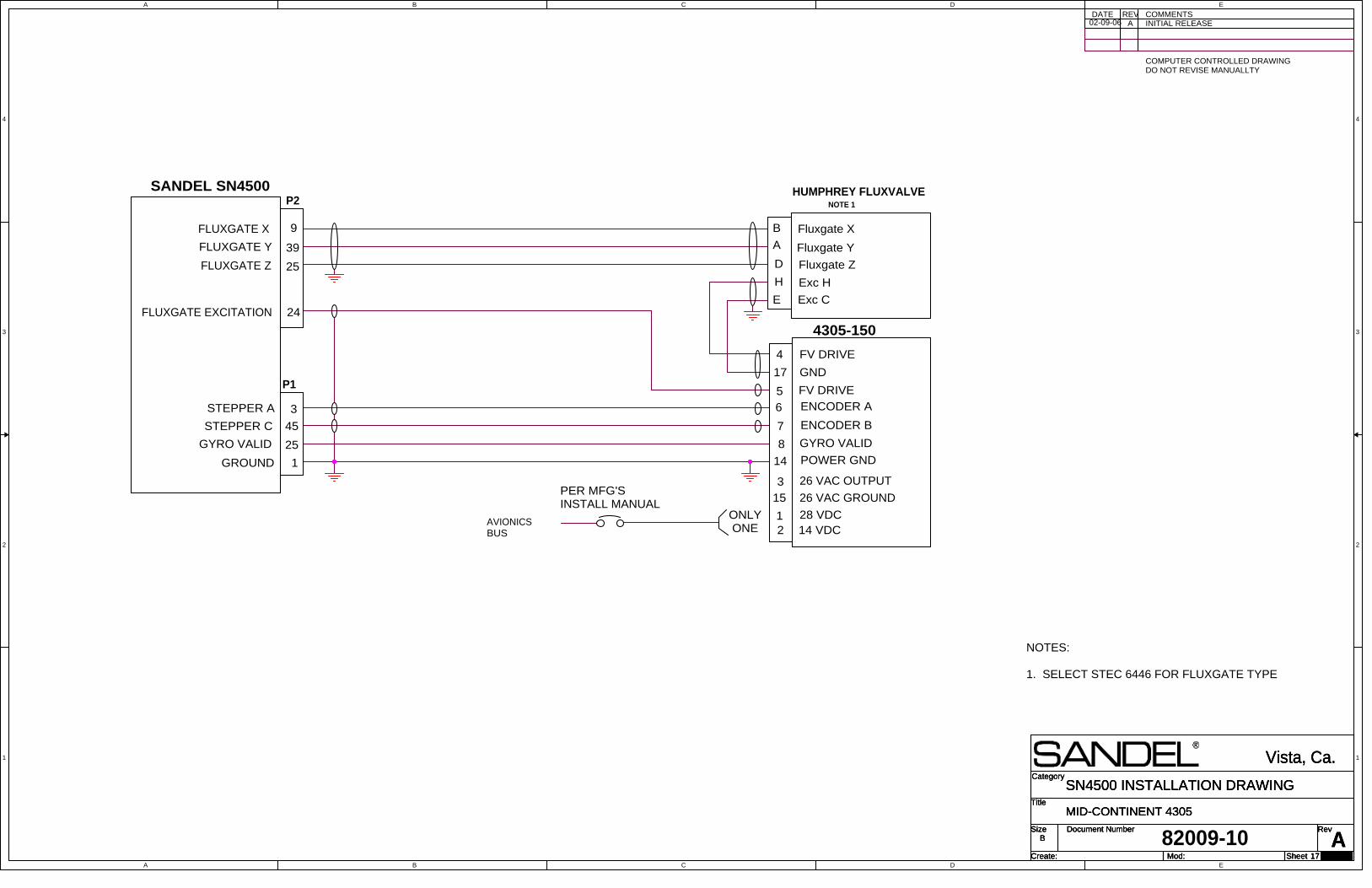
A
A
B
B
C
C
D
D
E
E
4 4
3 3
2 2
1 1
Title
Size Document Number Rev
Create: Sheet of
Category
Mod:
A
MID-CONTINENT 4305
Vista, Ca.
B
17 29
SN4500 INSTALLATION DRAWINGTitle
Size Document Number Rev
Create: Sheet of
Category
Mod:
A
MID-CONTINENT 4305
Vista, Ca.
B
17 29
SN4500 INSTALLATION DRAWINGTitle
Size Document Number Rev
Create: Sheet of
Category
Mod:
A
MID-CONTINENT 4305
Vista, Ca.
B
17 29
SN4500 INSTALLATION DRAWING
SANDEL SN4500
NOTES:
1. SELECT STEC 6446 FOR FLUXGATE TYPE
A INITIAL RELEASEDATE REV COMMENTS
COMPUTER CONTROLLED DRAWINGDO NOT REVISE MANUALLTY
9
39
25
1
24FLUXGATE EXCITATION
GROUND
FLUXGATE Y Fluxgate Y
Fluxgate X
FLUXGATE Z Fluxgate Z
AVIONICSBUS
Exc H
Exc C
GND
4
17
ENCODER A
7
6
GYRO VALID
45
D
STEPPER C ENCODER B
14
A
3
HUMPHREY FLUXVALVE
25 8
FV DRIVE
STEPPER A
GYRO VALID
B
POWER GND
28 VDC
E
H
FLUXGATE X
14 VDC
5 FV DRIVE
26 VAC OUTPUT
26 VAC GROUND
12
315
4305-150
ONLY ONE
P1
PER MFG'SINSTALL MANUAL
82009-10
P2 NOTE 1
02-09-06
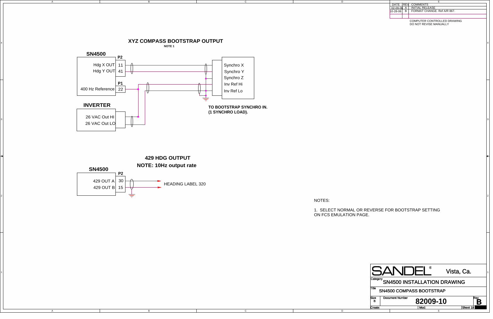
A
A
B
B
C
C
D
D
E
E
4 4
3 3
2 2
1 1
Title
Size Document Number Rev
Create: Sheet of
Category
Mod:B
SN4500 COMPASS BOOTSTRAP
Vista, Ca.
B
18 29
SN4500 INSTALLATION DRAWINGTitle
Size Document Number Rev
Create: Sheet of
Category
Mod:B
SN4500 COMPASS BOOTSTRAP
Vista, Ca.
B
18 29
SN4500 INSTALLATION DRAWINGTitle
Size Document Number Rev
Create: Sheet of
Category
Mod:B
SN4500 COMPASS BOOTSTRAP
Vista, Ca.
B
18 29
SN4500 INSTALLATION DRAWING
P2SN4500
30
15429 OUT B
429 OUT A
429 HDG OUTPUT
HEADING LABEL 320
COMMENTSINITIAL RELEASE
DATE REV
COMPUTER CONTROLLED DRAWINGDO NOT REVISE MANUALLY
A
22
Synchro X
Inv Ref Lo
11
TO BOOTSTRAP SYNCHRO IN. (1 SYNCHRO LOAD).
Synchro Y
P2
INVERTER
26 VAC Out LO
Hdg X OUT
SN4500
400 Hz Reference
XYZ COMPASS BOOTSTRAP OUTPUT
Synchro Z
Inv Ref Hi
26 VAC Out HI
41
NOTE: 10Hz output rate
P1
82009-10
Hdg Y OUT
NOTE 1
NOTES:
1. SELECT NORMAL OR REVERSE FOR BOOTSTRAP SETTINGON FCS EMULATION PAGE.
B FORMAT CHANGE. Ref A/R 867.02-09-06
10-28-06
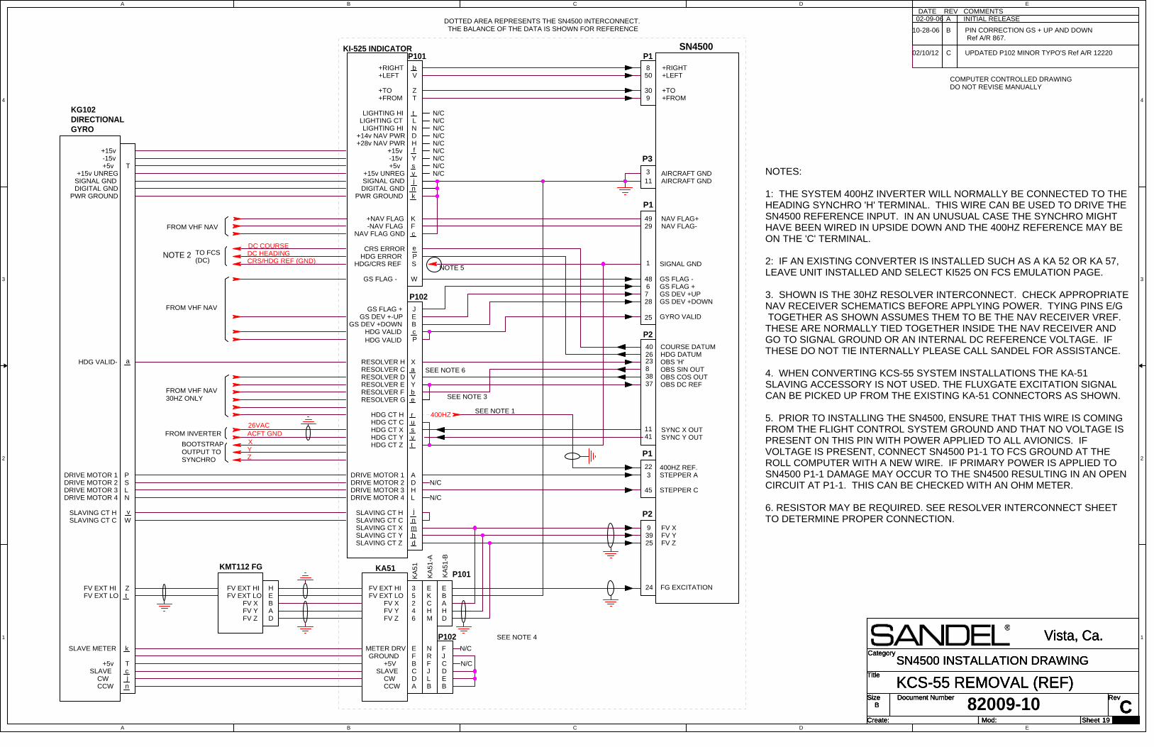
A
A
B
B
C
C
D
D
E
E
4 4
3 3
2 2
1 1
YXACFT GND26VAC
DC HEADINGDC COURSE
CRS/HDG REF (GND)
Z
400HZ
Title
Size Document Number Rev
Create: Sheet of
Category
Mod:C
KCS-55 REMOVAL (REF)
Vista, Ca.
B
19 29
SN4500 INSTALLATION DRAWINGTitle
Size Document Number Rev
Create: Sheet of
Category
Mod:C
KCS-55 REMOVAL (REF)
Vista, Ca.
B
19 29
SN4500 INSTALLATION DRAWINGTitle
Size Document Number Rev
Create: Sheet of
Category
Mod:C
KCS-55 REMOVAL (REF)
Vista, Ca.
B
19 29
SN4500 INSTALLATION DRAWING
COMMENTSDATEINITIAL RELEASEA
REV
NOTES:
1: THE SYSTEM 400HZ INVERTER WILL NORMALLY BE CONNECTED TO THEHEADING SYNCHRO 'H' TERMINAL. THIS WIRE CAN BE USED TO DRIVE THESN4500 REFERENCE INPUT. IN AN UNUSUAL CASE THE SYNCHRO MIGHTHAVE BEEN WIRED IN UPSIDE DOWN AND THE 400HZ REFERENCE MAY BEON THE 'C' TERMINAL.
2: IF AN EXISTING CONVERTER IS INSTALLED SUCH AS A KA 52 OR KA 57,LEAVE UNIT INSTALLED AND SELECT KI525 ON FCS EMULATION PAGE.
3. SHOWN IS THE 30HZ RESOLVER INTERCONNECT. CHECK APPROPRIATENAV RECEIVER SCHEMATICS BEFORE APPLYING POWER. TYING PINS E/G TOGETHER AS SHOWN ASSUMES THEM TO BE THE NAV RECEIVER VREF. THESE ARE NORMALLY TIED TOGETHER INSIDE THE NAV RECEIVER ANDGO TO SIGNAL GROUND OR AN INTERNAL DC REFERENCE VOLTAGE. IFTHESE DO NOT TIE INTERNALLY PLEASE CALL SANDEL FOR ASSISTANCE.
4. WHEN CONVERTING KCS-55 SYSTEM INSTALLATIONS THE KA-51SLAVING ACCESSORY IS NOT USED. THE FLUXGATE EXCITATION SIGNALCAN BE PICKED UP FROM THE EXISTING KA-51 CONNECTORS AS SHOWN.
5. PRIOR TO INSTALLING THE SN4500, ENSURE THAT THIS WIRE IS COMINGFROM THE FLIGHT CONTROL SYSTEM GROUND AND THAT NO VOLTAGE ISPRESENT ON THIS PIN WITH POWER APPLIED TO ALL AVIONICS. IFVOLTAGE IS PRESENT, CONNECT SN4500 P1-1 TO FCS GROUND AT THEROLL COMPUTER WITH A NEW WIRE. IF PRIMARY POWER IS APPLIED TOSN4500 P1-1 DAMAGE MAY OCCUR TO THE SN4500 RESULTING IN AN OPENCIRCUIT AT P1-1. THIS CAN BE CHECKED WITH AN OHM METER.
6. RESISTOR MAY BE REQUIRED. SEE RESOLVER INTERCONNECT SHEETTO DETERMINE PROPER CONNECTION.
P1
24
93925
GYRO VALID25
SN4500
FG EXCITATION
FV YFV Z
FV X
L
P
P102
S
s+15v UNREG
k
a
SLAVING CT HSLAVING CT CSLAVING CT X
d
LIGHTING HI
DIGITAL GND
RESOLVER H
RESOLVER F
RESOLVER D
b
HDG CT Z
HDG CT C
Z
D
L
+TO
c
GS DEV +DOWNGS DEV +-UP
j
-15v
v
J
BcP
X
LIGHTING CT
-NAV FLAG
H
N
+15v
e
SLAVING CT Y
HDG ERROR
fY
+5v
Y
HDG CT Y
HDG CT H
P101
+28v NAV PWR
NAV FLAG GND
RESOLVER C
DRIVE MOTOR 4
D
s
r
+14v NAV PWR
K
GS FLAG +
RESOLVER G
DRIVE MOTOR 1
DRIVE MOTOR 3
SLAVING CT Z
v
+RIGHTV+LEFT
E
V
n
n
F
HDG VALIDHDG VALID
LIGHTING HI
j
A
t
HDG CT X
T+FROM
PWR GROUND
+NAV FLAG
DRIVE MOTOR 2
t
HDG/CRS REF
H
RESOLVER E
m
SIGNAL GND
h
u
WGS FLAG -
CRS ERROR e
DRIVE MOTOR 2DRIVE MOTOR 3
DRIVE MOTOR 1
HDG VALID-
DRIVE MOTOR 4
KA
51
-A
4
KFV X
J
EA
FV Y
B
C
D
A
GROUND
B
C
FV EXT LO
NF
J
H
KA
51
-B
CCW
M
E
2H
R
SLAVE
METER DRV
D
3B
FV Z
FV EXT HI
6
E
L
KA
51
D
F
F
B
CW
5C
E
+5V
P101
P102
SIGNAL GND
PWR GROUNDDIGITAL GND
+15v-15v+5v
+15v UNREG
SLAVING CT HSLAVING CT C
PSLN
vW
E
FV YFV Z
FV EXT LOFV EXT HI
AD
FV X B
KMT112 FG
HFV EXT HIFV EXT LO
Z
FROM INVERTER
SEE NOTE 1
BOOTSTRAPOUTPUT TOSYNCHRO
P2
45
3
STEPPER C
STEPPER A22
1 SIGNAL GND
kSLAVE METER
CCWCW
SLAVE
T
+5v Tcjn
KA51
a
850
309
+TO
+RIGHT+LEFT
+FROM
48
287
GS FLAG -
GS DEV +UPGS DEV +DOWN
NAV FLAG+NAV FLAG-
4929
FROM VHF NAV
FROM VHF NAV
TO FCS(DC)
N/CN/CN/CN/CN/CN/CN/CN/C
N/C
N/C
N/C
N/C
KI-525 INDICATOR
KG102DIRECTIONALGYRO
DOTTED AREA REPRESENTS THE SN4500 INTERCONNECT. THE BALANCE OF THE DATA IS SHOWN FOR REFERENCE
23 OBS 'H'8 OBS SIN OUT38 OBS COS OUT37 OBS DC REF
SEE NOTE 3FROM VHF NAV30HZ ONLY
SEE NOTE 4
P1
NOTE 5
t
400HZ REF.
1141
6 GS FLAG +
SYNC Y OUT
SEE NOTE 6
26 HDG DATUM40 COURSE DATUM
NOTE 2
N/C
b
SYNC X OUT
P2
P1
P3
11 AIRCRAFT GND3
82009-10
COMPUTER CONTROLLED DRAWINGDO NOT REVISE MANUALLY
B PIN CORRECTION GS + UP AND DOWN Ref A/R 867.
AIRCRAFT GND
02-09-06
10-28-06
C UPDATED P102 MINOR TYPO'S Ref A/R 1222002/10/12
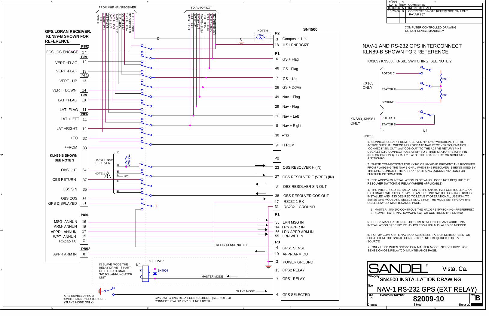
A
A
B
B
C
C
D
D
E
E
4 4
3 3
2 2
1 1
Title
Size Document Number Rev
Create: Sheet of
Category
Mod:
BNAV-1 RS-232 GPS (EXT RELAY)
Vista, Ca.
B
20 29
SN4500 INSTALLATION DRAWINGTitle
Size Document Number Rev
Create: Sheet of
Category
Mod:
BNAV-1 RS-232 GPS (EXT RELAY)
Vista, Ca.
B
20 29
SN4500 INSTALLATION DRAWINGTitle
Size Document Number Rev
Create: Sheet of
Category
Mod:
BNAV-1 RS-232 GPS (EXT RELAY)
Vista, Ca.
B
20 29
SN4500 INSTALLATION DRAWING
A INITIAL RELEASEDATE6/9/98
REVA
COMMENTS
GPS/LORAN RECEIVER. KLN89-B SHOWN FORREFERENCE.
VERT +FLAG
VERT -FLAG
VERT +UP
VERT +DOWN
LAT +FLAG
LAT -FLAG
LAT +RIGHT
LAT +LEFT
+FROM
+TO
F
H
D
E
TO VHF NAVRECEIVER
KLN89-B SHOWN
OBS OUT 34
37OBS RETURN
OBS COS 36
OBS SIN 35
GPS DISPLAYED 31
NOTE 1
SEE NOTE 3
6
OBS RESOLVER H (IN)
9
18
8
SN4500
23
28
8
+TO
OBS RESOLVER E (VREF) (IN)
49
OBS RESOLVER COS OUT
7
50
37
30
ILS1 ENERGIZE
38
29
+FROM
48
OBS RESOLVER SIN OUT
P2
GPS SELECTED
ACFT PWR
GPS1 RELAY
GPS SWITCHING RELAY CONNECTIONS (SEE NOTE 4)CONNECT P3-4 OR P3-7 BUT NOT BOTH.
7
4
K1
16
P1
35 LRN MSG IN
APPR- ANNUN18 14 LRN APPR INARM- ANNUN17 56 LRN APPR ARM IN
WPT- ANNUN 15 55 LRN WPT IN
APPR ARM IN 8
MSG- ANNUN
10 APPR ARM OUT
P3RS232-TX
3
P891
P892
P891
P892
12
13
13
14
10
11
11
12
32
33
P891
P892
!
MASTER MODE
SLAVE MODE
IN SLAVE MODE THERELAY DRIVE IS PARTOF THE EXTERNALSWITCH/ANNUNCIATORUNIT
GPS ENABLED FROMSWITCH/ANNUNCIATOR UNIT.(SLAVE MODE ONLY)
G N/C
15 GPS2 RELAY
NOTE 6LA
T +
RIG
HT
LA
T +
LE
FT
LA
T -
FLA
GLA
T +
FLA
GV
ER
T +
DO
WN
VE
RT
+U
PV
ER
T -
FLA
GV
ER
T +
FLA
GIL
S1 E
NE
RG
IZE
TO AUTOPILOT
C
NOTES:
1. CONNECT OBS "H" FROM RECEIVER "H" or "C" WHICHEVER IS THEACTIVE OUTPUT. CHECK APPROPRIATE NAV RECEIVER SCHEMATICS. CONNECT "SIN OUT" and "COS OUT" TO THE ACTIVE RETURN PINS,USUALLY D/F. CONNECT "OBS VREF" TO EITHER STATOR RETURN PIN(REF OR GROUND) USUALLY E or G. THE LOAD RESISTOR SIMULATESA SYNCHRO.
2. THESE CONNECTIONS FOR KX165 OR KNX80/81 PREVENT THE RECEIVERFROM FLAGGING THE NAV SIGNAL WHEN THE RESOLVER IS BEING USED BYTHE GPS. CONSULT THE APPROPRIATE KING DOCUMENTATION FORFURTHER INFORMATION.
3. SEE ARINC-429 INSTALLATION PAGE WHICH DOES NOT REQUIRE THERESOLVER SWITCHING RELAY (WHERE APPLICABLE).
4. THE PREFERRED INSTALLATION IS THE SN4500 P3-7 CONTROLLING ANEXTERNAL SWITCHING RELAY. IF AN EXISTING SWITCH CONTROL BOX ISINSTALLED AND IT IS DESIRED TO LEAVE IT OPERATIONAL, USE P3-4 TOSENSE GPS MODE AND SELECT SLAVE FOR THE MODE SETTING ON THEOBS/RELAY/CDI MAINTENANCE PAGE.
5. CHECK MANUFACTURERS DOCUMENTATION FOR ANY ADDITIONALINSTALLATION SPECIFIC RELAY POLES WHICH MAY ALSO BE NEEDED.
6. FOR 3V COMPOSITE NAV SOURCES INSERT A 470K SERIES RESISTORLOCATED AT THE SN4500 CONNECTOR. NOT REQUIRED FOR .5VSOURCE.
1 MASTER: SN4500 CONTROLS THE NAV/GPS SWITCHING (PREFERRED)2 SLAVE: EXTERNAL NAV/GPS SWITCH CONTROLS THE SN4500
KNS80, KNS81ONLY
STATOR F
STATOR D
GROUND
ROTOR H
ROTOR C
KX165ONLY
K1
DO NOT REVISE MANUALLY
7. ONLY USED WHEN SN4500 IS IN MASTER MODE. SELECT GPS1 FORSENSE ON OBS/RELAY/CDI MAINTENANCE PAGE.
GPS1 SENSE
LA
T +
FLA
G
LA
T +
LE
FT
VE
RT
+F
LA
GIL
S E
NE
RG
IZE
VE
RT
-F
LA
G
+T
OLA
T +
RIG
HT
VE
RT
+D
OW
N
+F
RO
M
LA
T -
FLA
G
CO
MP
OS
ITE
1
FROM VHF NAV RECEIVER
VE
RT
+U
P
P892
17FCS LOC ENGAGE
Nav + Right
Nav + Left
Nav + Flag
Nav - Flag
GS - Flag
GS + Flag
GS + Up
GS + Down
Composite 1 In
RELAY SENSE NOTE 7
KX165 / KNS80 / KNS81 SWITCHING, SEE NOTE 2
NAV-1 AND RS-232 GPS INTERCONNECTKLN89-B SHOWN FOR REFERENCEP1
P2
4
2
17RS232-1 GROUND
82009-10
31RS232-1 RX
3 POWER GROUND
COMPUTER CONTROLLED DRAWING
B CORRECTED NOTE REFERENCE CALLOUT Ref A/R 867.
02-09-0610-28-06
1N40041N4004
470K
470K
33K33K
33K33K
22
0 O
hm
22
0 O
hm
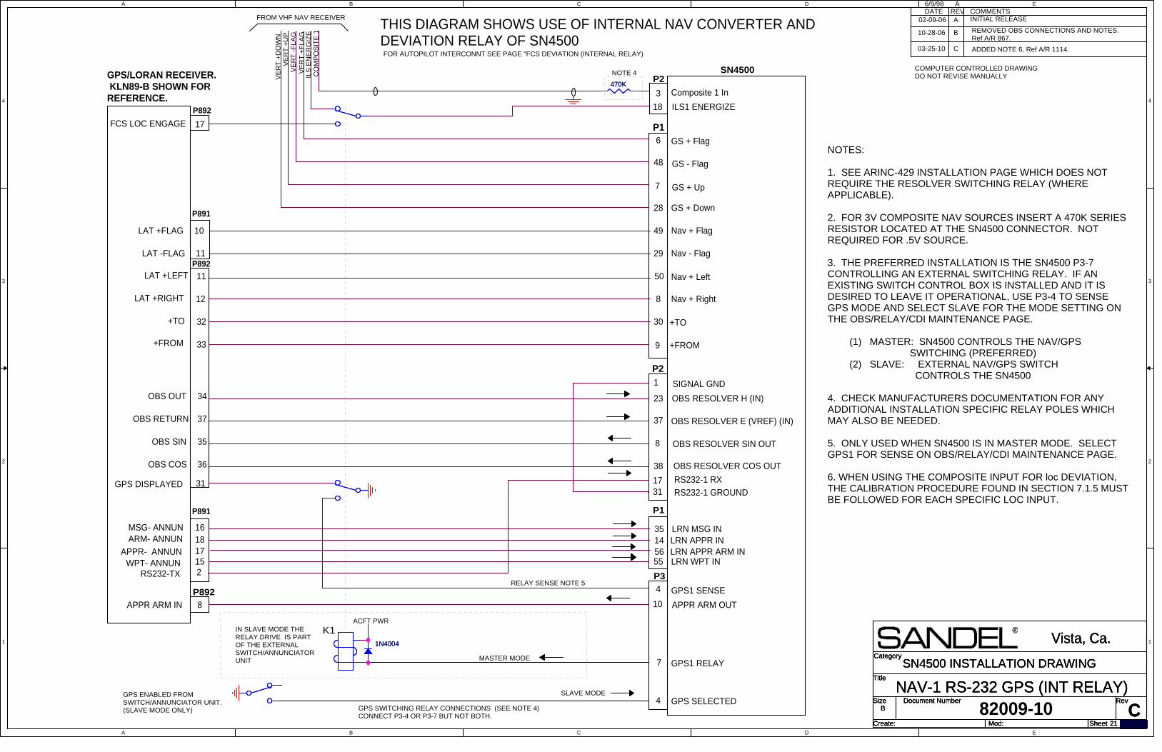
A
A
B
B
C
C
D
D
E
E
4 4
3 3
2 2
1 1
Title
Size Document Number Rev
Create: Sheet of
Category
Mod:C
NAV-1 RS-232 GPS (INT RELAY)
Vista, Ca.
B
21 29
SN4500 INSTALLATION DRAWINGTitle
Size Document Number Rev
Create: Sheet of
Category
Mod:C
NAV-1 RS-232 GPS (INT RELAY)
Vista, Ca.
B
21 29
SN4500 INSTALLATION DRAWINGTitle
Size Document Number Rev
Create: Sheet of
Category
Mod:C
NAV-1 RS-232 GPS (INT RELAY)
Vista, Ca.
B
21 29
SN4500 INSTALLATION DRAWING
A INITIAL RELEASEDATE6/9/98
REVA
COMMENTS
GPS/LORAN RECEIVER. KLN89-B SHOWN FORREFERENCE.
OBS OUT 34
37OBS RETURN
OBS COS 36
OBS SIN 35
GPS DISPLAYED 31
6
OBS RESOLVER H (IN)
9
18
8
SN4500
23
28
8
+TO
OBS RESOLVER E (VREF) (IN)
49
OBS RESOLVER COS OUT
7
50
37
30
ILS1 ENERGIZE
38
29
+FROM
48
OBS RESOLVER SIN OUT
P2
GPS SELECTED
ACFT PWR
GPS1 RELAY7
4
K1
16
P1
35 LRN MSG IN
APPR- ANNUN18 14 LRN APPR INARM- ANNUN17 56 LRN APPR ARM IN
WPT- ANNUN 15 55 LRN WPT IN
APPR ARM IN 8
MSG- ANNUN
10 APPR ARM OUT
P3RS232-TX
3
P891
P892
MASTER MODE
SLAVE MODE
IN SLAVE MODE THERELAY DRIVE IS PARTOF THE EXTERNALSWITCH/ANNUNCIATORUNIT
GPS ENABLED FROMSWITCH/ANNUNCIATOR UNIT.(SLAVE MODE ONLY)
NOTE 4
NOTES:
1. SEE ARINC-429 INSTALLATION PAGE WHICH DOES NOTREQUIRE THE RESOLVER SWITCHING RELAY (WHEREAPPLICABLE).
2. FOR 3V COMPOSITE NAV SOURCES INSERT A 470K SERIESRESISTOR LOCATED AT THE SN4500 CONNECTOR. NOTREQUIRED FOR .5V SOURCE.
3. THE PREFERRED INSTALLATION IS THE SN4500 P3-7CONTROLLING AN EXTERNAL SWITCHING RELAY. IF ANEXISTING SWITCH CONTROL BOX IS INSTALLED AND IT ISDESIRED TO LEAVE IT OPERATIONAL, USE P3-4 TO SENSEGPS MODE AND SELECT SLAVE FOR THE MODE SETTING ONTHE OBS/RELAY/CDI MAINTENANCE PAGE. (1) MASTER: SN4500 CONTROLS THE NAV/GPS SWITCHING (PREFERRED) (2) SLAVE: EXTERNAL NAV/GPS SWITCH CONTROLS THE SN4500
4. CHECK MANUFACTURERS DOCUMENTATION FOR ANYADDITIONAL INSTALLATION SPECIFIC RELAY POLES WHICHMAY ALSO BE NEEDED.
5. ONLY USED WHEN SN4500 IS IN MASTER MODE. SELECTGPS1 FOR SENSE ON OBS/RELAY/CDI MAINTENANCE PAGE.
6. WHEN USING THE COMPOSITE INPUT FOR loc DEVIATION,THE CALIBRATION PROCEDURE FOUND IN SECTION 7.1.5 MUSTBE FOLLOWED FOR EACH SPECIFIC LOC INPUT.
COMPUTER CONTROLLED DRAWINGDO NOT REVISE MANUALLY
GPS1 SENSE
VE
RT
+F
LA
GIL
S E
NE
RG
IZE
VE
RT
-F
LA
G
VE
RT
+D
OW
N
CO
MP
OS
ITE
1
FROM VHF NAV RECEIVER
VE
RT
+U
P
P892
17FCS LOC ENGAGE
Nav + Right
Nav + Left
Nav + Flag
Nav - Flag
GS - Flag
GS + Flag
GS + Up
GS + Down
Composite 1 In
P1
P2
4
2
17RS232-1 GROUND
82009-10
31RS232-1 RX
1 SIGNAL GND
FOR AUTOPILOT INTERCONNT SEE PAGE "FCS DEVIATION (INTERNAL RELAY)
THIS DIAGRAM SHOWS USE OF INTERNAL NAV CONVERTER ANDDEVIATION RELAY OF SN4500
GPS SWITCHING RELAY CONNECTIONS (SEE NOTE 4)CONNECT P3-4 OR P3-7 BUT NOT BOTH.
RELAY SENSE NOTE 5
LAT +FLAG
LAT -FLAG
LAT +RIGHT
LAT +LEFT
+FROM
+TO
P892
10
11
11
12
32
33
P891
B REMOVED OBS CONNECTIONS AND NOTES.Ref A/R 867.
02-09-06
10-28-06
03-25-10 ADDED NOTE 6, Ref A/R 1114.C
1N40041N4004
470K
470K
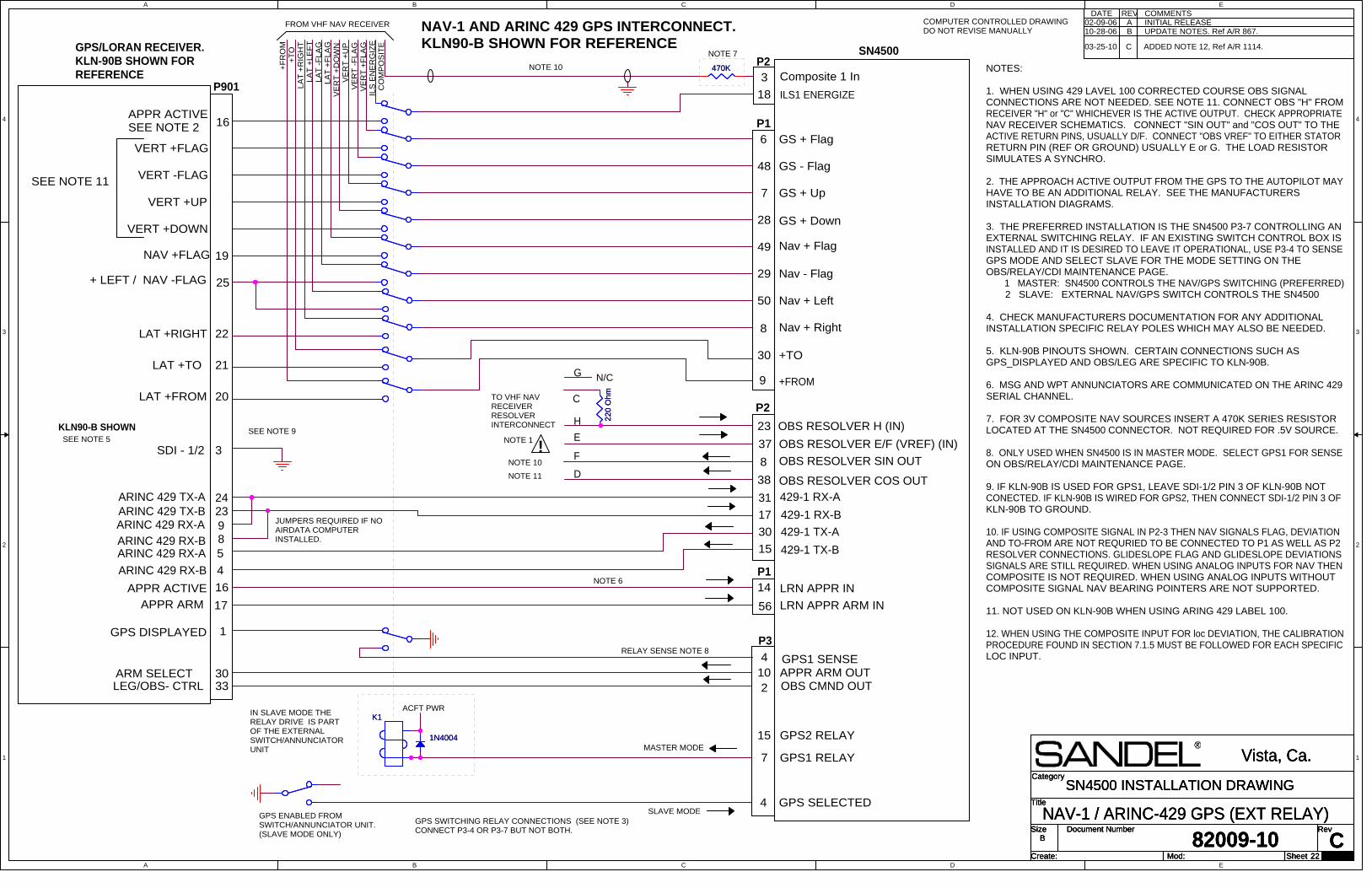
A
A
B
B
C
C
D
D
E
E
4 4
3 3
2 2
1 1
Title
Size Document Number Rev
Create: Sheet of
Category
Mod:
82009-10 CNAV-1 / ARINC-429 GPS (EXT RELAY)
Vista, Ca.
B
22 29
SN4500 INSTALLATION DRAWINGTitle
Size Document Number Rev
Create: Sheet of
Category
Mod:
82009-10 CNAV-1 / ARINC-429 GPS (EXT RELAY)
Vista, Ca.
B
22 29
SN4500 INSTALLATION DRAWINGTitle
Size Document Number Rev
Create: Sheet of
Category
Mod:
82009-10 CNAV-1 / ARINC-429 GPS (EXT RELAY)
Vista, Ca.
B
22 29
SN4500 INSTALLATION DRAWINGGPS SELECTED4
ACFT PWR
ARM SELECT APPR ARM OUTOBS CMND OUTLEG/OBS- CTRL
NAV-1 AND ARINC 429 GPS INTERCONNECT.KLN90-B SHOWN FOR REFERENCE
GPS1 RELAY7
15 GPS2 RELAYMASTER MODE
SLAVE MODEGPS ENABLED FROMSWITCH/ANNUNCIATOR UNIT.(SLAVE MODE ONLY)
429-1 TX-A
1
N/C
LA
T +
LE
FT
VE
RT
-F
LA
G
H
TO VHF NAVRECEIVERRESOLVERINTERCONNECT
OBS RESOLVER E/F (VREF) (IN)
OBS RESOLVER COS OUT
GPS/LORAN RECEIVER. KLN-90B SHOWN FORREFERENCE
OBS RESOLVER H (IN)
2
!
LA
T +
RIG
HT
LA
T -
FLA
G
F
E
APPR ACTIVESEE NOTE 2
P2
GPS DISPLAYED
429-1 RX-B
NOTE 7
VE
RT
+U
P
CO
MP
OS
ITE
ARINC 429 RX-B
10
NOTE 1
VE
RT
+D
OW
N
ARINC 429 TX-B
VE
RT
+F
LA
G
D
SN4500
16
OBS RESOLVER SIN OUT
ARINC 429 RX-A 429-1 TX-B
+T
O
ARINC 429 TX-A
+F
RO
M
G
P901
FROM VHF NAV RECEIVER
LA
T +
FLA
G
GPS SWITCHING RELAY CONNECTIONS (SEE NOTE 3)CONNECT P3-4 OR P3-7 BUT NOT BOTH.
LRN APPR IN14P1
56 LRN APPR ARM IN
APPR ACTIVE 16
17
NOTE 6
ARINC 429 RX-AARINC 429 RX-B
JUMPERS REQUIRED IF NOAIRDATA COMPUTERINSTALLED.
A INITIAL RELEASEDATE REV COMMENTS
C
NOTES:
1. WHEN USING 429 LAVEL 100 CORRECTED COURSE OBS SIGNALCONNECTIONS ARE NOT NEEDED. SEE NOTE 11. CONNECT OBS "H" FROMRECEIVER "H" or "C" WHICHEVER IS THE ACTIVE OUTPUT. CHECK APPROPRIATENAV RECEIVER SCHEMATICS. CONNECT "SIN OUT" and "COS OUT" TO THEACTIVE RETURN PINS, USUALLY D/F. CONNECT "OBS VREF" TO EITHER STATORRETURN PIN (REF OR GROUND) USUALLY E or G. THE LOAD RESISTORSIMULATES A SYNCHRO.
2. THE APPROACH ACTIVE OUTPUT FROM THE GPS TO THE AUTOPILOT MAYHAVE TO BE AN ADDITIONAL RELAY. SEE THE MANUFACTURERS INSTALLATION DIAGRAMS.
3. THE PREFERRED INSTALLATION IS THE SN4500 P3-7 CONTROLLING ANEXTERNAL SWITCHING RELAY. IF AN EXISTING SWITCH CONTROL BOX ISINSTALLED AND IT IS DESIRED TO LEAVE IT OPERATIONAL, USE P3-4 TO SENSEGPS MODE AND SELECT SLAVE FOR THE MODE SETTING ON THEOBS/RELAY/CDI MAINTENANCE PAGE. 1 MASTER: SN4500 CONTROLS THE NAV/GPS SWITCHING (PREFERRED) 2 SLAVE: EXTERNAL NAV/GPS SWITCH CONTROLS THE SN4500
4. CHECK MANUFACTURERS DOCUMENTATION FOR ANY ADDITIONALINSTALLATION SPECIFIC RELAY POLES WHICH MAY ALSO BE NEEDED.
5. KLN-90B PINOUTS SHOWN. CERTAIN CONNECTIONS SUCH ASGPS_DISPLAYED AND OBS/LEG ARE SPECIFIC TO KLN-90B.
6. MSG AND WPT ANNUNCIATORS ARE COMMUNICATED ON THE ARINC 429SERIAL CHANNEL.
7. FOR 3V COMPOSITE NAV SOURCES INSERT A 470K SERIES RESISTORLOCATED AT THE SN4500 CONNECTOR. NOT REQUIRED FOR .5V SOURCE.
8. ONLY USED WHEN SN4500 IS IN MASTER MODE. SELECT GPS1 FOR SENSEON OBS/RELAY/CDI MAINTENANCE PAGE.
9. IF KLN-90B IS USED FOR GPS1, LEAVE SDI-1/2 PIN 3 OF KLN-90B NOTCONECTED. IF KLN-90B IS WIRED FOR GPS2, THEN CONNECT SDI-1/2 PIN 3 OFKLN-90B TO GROUND.
10. IF USING COMPOSITE SIGNAL IN P2-3 THEN NAV SIGNALS FLAG, DEVIATIONAND TO-FROM ARE NOT REQURIED TO BE CONNECTED TO P1 AS WELL AS P2RESOLVER CONNECTIONS. GLIDESLOPE FLAG AND GLIDESLOPE DEVIATIONSSIGNALS ARE STILL REQUIRED. WHEN USING ANALOG INPUTS FOR NAV THENCOMPOSITE IS NOT REQUIRED. WHEN USING ANALOG INPUTS WITHOUTCOMPOSITE SIGNAL NAV BEARING POINTERS ARE NOT SUPPORTED.
11. NOT USED ON KLN-90B WHEN USING ARING 429 LABEL 100.
12. WHEN USING THE COMPOSITE INPUT FOR loc DEVIATION, THE CALIBRATIONPROCEDURE FOUND IN SECTION 7.1.5 MUST BE FOLLOWED FOR EACH SPECIFICLOC INPUT.
RELAY SENSE NOTE 84 GPS1 SENSE
COMPUTER CONTROLLED DRAWINGDO NOT REVISE MANUALLY
6
9
28
8
+TO
49
7
50
30
29
+FROM
48
18
3
8
23
37
38
Nav + Right
Nav + Left
Nav + Flag
Nav - Flag
GS - Flag
GS + Flag
GS + Up
GS + Down
Composite 1 In
APPR ARM
VERT +FLAG
VERT -FLAG
VERT +UP
VERT +DOWN
NAV +FLAG
+ LEFT / NAV -FLAG
LAT +TO
LAT +RIGHT
19
25
22
21
IN SLAVE MODE THERELAY DRIVE IS PARTOF THE EXTERNALSWITCH/ANNUNCIATORUNIT
ILS1 ENERGIZEILS
EN
ER
GIZ
E
KLN90-B SHOWN
P1
P2
P3
3033
429-1 RX-A
5
4
30
15
31
1798
2423
NOTE 10
LAT +FROM 20
SEE NOTE 11
NOTE 10
NOTE 11
SDI - 1/2 3
SEE NOTE 9SEE NOTE 5
B UPDATE NOTES. Ref A/R 867.02-09-0610-28-06
ADDED NOTE 12, Ref A/R 1114.03-25-10 C
470K
470K
22
0 O
hm
22
0 O
hm
1N40041N4004
K1K1

A
A
B
B
C
C
D
D
E
E
4 4
3 3
2 2
1 1
Title
Size Document Number Rev
Create: Sheet of
Category
Mod:
82009-10 CNAV-1 / ARINC-429 GPS (INT RELAY)
Vista, Ca.
B
23 29
SN4500 INSTALLATION DRAWINGTitle
Size Document Number Rev
Create: Sheet of
Category
Mod:
82009-10 CNAV-1 / ARINC-429 GPS (INT RELAY)
Vista, Ca.
B
23 29
SN4500 INSTALLATION DRAWINGTitle
Size Document Number Rev
Create: Sheet of
Category
Mod:
82009-10 CNAV-1 / ARINC-429 GPS (INT RELAY)
Vista, Ca.
B
23 29
SN4500 INSTALLATION DRAWING
GPS SELECTED4
ACFT PWR
ARM SELECT APPR ARM OUTOBS CMND OUTLEG/OBS- CTRL
NAV-1 AND ARINC 429 GPS INTERCONNECT.KLN90-B SHOWN FOR REFERENCE
GPS1 RELAY7
15 GPS2 RELAYMASTER MODE
SLAVE MODEGPS ENABLED FROMSWITCH/ANNUNCIATOR UNIT.(SLAVE MODE ONLY)
429-1 TX-A
1
VE
RT
-F
LA
GGPS/LORAN RECEIVER. KLN-90B SHOWN FORREFERENCE
2
APPR ACTIVESEE NOTE 1
P2
GPS DISPLAYED
429-1 RX-B
NOTE 7
VE
RT
+U
P
CO
MP
OS
ITE
ARINC 429 RX-B
10
VE
RT
+D
OW
N
ARINC 429 TX-B
VE
RT
+F
LA
G
SN4500
16
ARINC 429 RX-A
429-1 TX-B
ARINC 429 TX-A
P901
FROM VHF NAV RECEIVER
GPS SWITCHING RELAY CONNECTIONS (SEE NOTE 3)CONNECT P3-4 OR P3-7 BUT NOT BOTH.
LRN APPR IN14
P1
56 LRN APPR ARM IN
APPR ACTIVE 1617
NOTE 5
ARINC 429 RX-AARINC 429 RX-B
JUMPERS REQUIRED IF NOAIRDATA COMPUTERINSTALLED.
A INITIAL RELEASEDATE REV COMMENTS
NOTES:
1. THE APPROACH ACTIVE OUTPUT FROM THE GPS TO THE AUTOPILOT MAY HAVE TO BE ANADDITIONAL RELAY. SEE THE MANUFACTURERS INSTALLATION DIAGRAMS.
2. THE PREFERRED INSTALLATION IS THE SN4500 P3-7 CONTROLLING AN EXTERNALSWITCHING RELAY. IF AN EXISTING SWITCH CONTROL BOX IS INSTALLED AND IT ISDESIRED TO LEAVE IT OPERATIONAL, USE P3-4 TO SENSE GPS MODE AND SELECT SLAVEFOR THE MODE SETTING ON THE OBS/RELAY/CDI MAINTENANCE PAGE.
(1) MASTER: SN4500 CONTROLS THE NAV/GPS SWITCHING (PREFERRED)
(2) SLAVE: EXTERNAL NAV/GPS SWITCH CONTROLS THE SN4500
3. CHECK MANUFACTURERS DOCUMENTATION FOR ANY ADDITIONAL INSTALLATIONSPECIFIC RELAY POLES WHICH MAY ALSO BE NEEDED.
4. KLN-90B PINOUTS SHOWN. CERTAIN CONNECTIONS SUCH AS GPS_DISPLAYED ANDOBS/LEG ARE SPECIFIC TO KLN-90B.
5. MSG AND WPT ANNUNCIATORS ARE COMMUNICATED ON THE ARINC 429 SERIALCHANNEL.
6. FOR 3V COMPOSITE NAV SOURCES INSERT A 470K SERIES RESISTOR LOCATED AT THESN4500 CONNECTOR. NOT REQUIRED FOR .5V SOURCE.
7. ONLY USED WHEN SN4500 IS IN MASTER MODE. SELECT GPS1 FOR SENSE ONOBS/RELAY/CDI MAINTENANCE PAGE.
8. IF KLN-90B ISUSED FOR GPS1, LEAVE SDI-1/2 PIN 3 OPEN. IF THE KLN-90B IS WIRED FORGPS2 THEN GROUND P901-3 AT THE GPS.
9. WHEN USING THE COMPOSITE INPUT FOR loc DEVIATION,THE CALIBRATION PROCEDURE FOUND IN SECTION 7.1.5 MUSTBE FOLLOWED FOR EACH SPECIFIC LOC INPUT.
RELAY SENSE NOTE 74 GPS1 SENSE
COMPUTER CONTROLLED DRAWINGDO NOT REVISE MANUALLY
6
28
7
48
18
3
GS - Flag
GS + Flag
GS + Up
GS + Down
Composite 1 In
APPR ARM
IN SLAVE MODE THERELAY DRIVE IS PARTOF THE EXTERNALSWITCH/ANNUNCIATORUNIT
ILS1 ENERGIZEILS
EN
ER
GIZ
E
KLN90-B SHOWNSEE NOTE 4
P1
P2
P3
3033
429-1 RX-A
5
4
30
15
31
1798
2423
THIS DIAGRAM SHOWS USE OF INTERNAL NAV CONVERTER ANDDEVIATION RELAY OF SN4500
SDI - 1/2 3SEE NOTE 8
B UPDATE NOTES. Ref A/R 867.
02-09-0610-28-06
ADDED NOTE 9, Ref A/R 1114.C03-25-10
470K
470K
1N40041N4004
K1K1

A
A
B
B
C
C
D
D
E
E
4 4
3 3
2 2
1 1
Title
Size Document Number Rev
Create: Sheet of
Category
Mod:
DNAV-2, GPS-2 (RS232), SUPERFLAGS
Vista, Ca.
B
24 29
SN4500 INSTALLATION DRAWINGTitle
Size Document Number Rev
Create: Sheet of
Category
Mod:
DNAV-2, GPS-2 (RS232), SUPERFLAGS
Vista, Ca.
B
24 29
SN4500 INSTALLATION DRAWINGTitle
Size Document Number Rev
Create: Sheet of
Category
Mod:
DNAV-2, GPS-2 (RS232), SUPERFLAGS
Vista, Ca.
B
24 29
SN4500 INSTALLATION DRAWING
SN4500P2
35 COMP. NAV #2 IN
VHF NAV #2NAV #2
NOTE 219 NAV-2 ILS ENERG.
COMP. NAV OUT
ILS ENERGIZE
NAV2 RELAY OUT8TO NAV2 RELAY COIL
NOTE 2
NOTE 1
P3
DATE REV COMMENTS
NOTES:
1. FOR 3V COMPOSITE NAV SOURCES INSERT A 470K SERIES RESISTORLOCATED AT THE SN3500 CONNECTOR. NOT REQUIRED FOR 0.5V SOURCE.
2. ILS ENERGIZE AND RELAY SWITCHING OUTPUT ARE ONLY REQUIRED IFNAV-2 IS TO BE USED AS A SECOND PRIMARY VHF NAV RECEIVER. IN THISCONFIGURATION A 2ND SWITCHING RELAY IS ADDED TO SWITCH THE DBARAND FLAG INPUTS FROM THE 2ND RECEIVER IN THE SAME MANNER AS THEGPS SWITCHING RELAY SHOWN FOR NAV-1 ON THE PREVIOUS PAGE.
3. WHEN USING THE COMPOSITE INPUT FOR loc DEVIATION, THECALIBRATION PROCEDURE FOUND IN SECTION 7.1.5 MUST BE FOLLOWEDFOR EACH SPECIFIC LOC INPUT.
ADATE
DO NOT REVISE MANUALLY
INITIAL RELEASE
COMPUTER CONTROLLED DRAWING
RS232-TX
2
32 RS232-2 RX
RS232-2 GROUND
GPS-2
REV COMMENTS
82009-10
P2
5 NAV2 RELAY SENSEFROM NAV2 RELAY GND CLOSURE
GND
GS LL FLAG IN +
GS LL FLAG IN -
LAT LL FLAG IN +
LAT LL FLAG IN -
6
48
49
29
28 VDC G/S SUPER FLAG OPTION
28 VDC NAV SUPER FLAG OPTION
B ADDED SUPER FLAG OPTION. Ref A/R 867.
P1
02-09-06
10-28-06
03-25-10 C ADDED NOTE 3, Ref A/R 1114.
11/13/13 D TITLE UPDATED TO INCLUDE SUPERFLAGS
1K 1/4 WATT1K 1/4 WATT
470K
470K
115K 1/4 WATT115K 1/4 WATT
1K 1/4 WATT1K 1/4 WATT
115K 1/4 WATT115K 1/4 WATT

A
A
B
B
C
C
D
D
E
E
4 4
3 3
2 2
1 1
Title
Size Document Number Rev
Create: Sheet of
Category
Mod:
AKLN-94 INTERFACE WITH ANALOG NAV
Vista, Ca.
B
25 29
SN4500 INSTALLATION DRAWINGTitle
Size Document Number Rev
Create: Sheet of
Category
Mod:
AKLN-94 INTERFACE WITH ANALOG NAV
Vista, Ca.
B
25 29
SN4500 INSTALLATION DRAWINGTitle
Size Document Number Rev
Create: Sheet of
Category
Mod:
AKLN-94 INTERFACE WITH ANALOG NAV
Vista, Ca.
B
25 29
SN4500 INSTALLATION DRAWING
A INITIAL RELEASEDATE6/9/98
REVA
COMMENTS
KLN-94 GPS RECEIVER WITHANALOG NAV
VERT +FLAG
VERT -FLAG
VERT +UP
VERT +DOWN
LAT +FLAG
LAT -FLAG
LAT +RIGHT
LAT +LEFT
+FROM
+TO
F
H
D
E
TO VHF NAVRECEIVER
KLN-94 SHOWN
OBS OUT 34
37OBS RETURN
OBS COS 36
OBS SIN 35
GPS DISPLAYED 31
NOTE 1
SEE NOTE 3
6
OBS RESOLVER H (IN)
9
18
8
SN4500
23
28
8
+TO
OBS RESOLVER E (VREF) (IN)
49
OBS RESOLVER COS OUT
7
50
37
30
ILS1 ENERGIZE
38
29
+FROM
48
OBS RESOLVER SIN OUT
P2
GPS SELECTED
ACFT PWR
GPS1 RELAY
GPS SWITCHING RELAY CONNECTIONS (SEE NOTE 4)CONNECT P3-4 OR P3-7 BUT NOT BOTH.
7
4
K1
16
P1
35 LRN MSG IN
APPR- ANNUN18 14 LRN APPR INARM- ANNUN17 56 LRN APPR ARM IN
WPT- ANNUN 15 55 LRN WPT IN
APPR ARM IN 8
MSG- ANNUN
10 APPR ARM OUT
P3RS232-TX
P941
P942
P941
P942
12
13
13
14
10
11
11
12
32
33
P941
P942
!
MASTER MODE
SLAVE MODE
IN SLAVE MODE THERELAY DRIVE IS PARTOF THE EXTERNALSWITCH/ANNUNCIATORUNIT
GPS ENABLED FROMSWITCH/ANNUNCIATOR UNIT.(SLAVE MODE ONLY)
G N/C
15 GPS2 RELAY
C
NOTES:
1. CONNECT OBS "H" FROM RECEIVER "H" or "C" WHICHEVER IS THE ACTIVE OUTPUT. CHECK APPROPRIATE NAV RECEIVER SCHEMATICS. CONNECT "SIN OUT" and "COSOUT" TO THE ACTIVE RETURN PINS, USUALLY D/F. CONNECT "OBS VREF" TO EITHERSTATOR RETURN PIN (REF OR GROUND) USUALLY E or G. THE LOAD RESISTORSIMULATES A SYNCHRO.
2. THESE CONNECTIONS FOR KX165 OR KNX80/81 PREVENT THE RECEIVER FROMFLAGGING THE NAV SIGNAL WHEN THE RESOLVER IS BEING USED BY THE GPS. CONSULT THE APPROPRIATE KING DOCUMENTATION FOR FURTHER INFORMATION.
3. KLN-94 MUST BE SET FOR "EXTENDED RS-232" ON MAINTENANCE PAGE 7 OF THEKLN-94.
4. THE PREFERRED INSTALLATION IS THE SN4500 P3-7 CONTROLLING AN EXTERNALSWITCHING RELAY. IF AN EXISTING SWITCH CONTROL BOX IS INSTALLED AND IT ISDESIRED TO LEAVE IT OPERATIONAL, USE P3-4 TO SENSE GPS MODE AND SELECTSLAVE FOR THE MODE SETTING ON THE OBS/RELAY/CDI MAINTENANCE PAGE.
(1) MASTER: SN4500 CONTROLS THE NAV/GPS SWITCHING (PREFERRED) (2) SLAVE: EXTERNAL NAV/GPS SWITCH CONTROLS THE SN4500
5. CHECK MANUFACTURERS DOCUMENTATION FOR ANY ADDITIONAL INSTALLATIONSPECIFIC RELAY POLES WHICH MAY ALSO BE NEEDED.
6. ONLY USED WHEN SN4500 IS CONFIGURED AS MASTER. SELECT GPS1 FOR SENSEON OBS/RELAY/CDI MAINTENACE PAGE.
7. NAV BEARING POINTER IS NOT SUPPORTED IN THIS CONFIGURATION. FOR NAVBEARING POINTER CONNECT COMPOSITE NAV SIGNAL TO SN4500 IF AVAILABLE.
KNS80, KNS81ONLY
STATOR F
STATOR D
GROUND
ROTOR H
ROTOR C
KX165ONLY
K1
DO NOT REVISE MANUALLY
GPS1 SENSE
LA
T +
FLA
G
LA
T +
LE
FT
VE
RT
+F
LA
GIL
S E
NE
RG
IZE
VE
RT
-F
LA
G
+T
OLA
T +
RIG
HT
VE
RT
+D
OW
N
+F
RO
M
LA
T -
FLA
G
FROM VHF NAV RECEIVER
VE
RT
+U
P
P942
17FCS LOC ENGAGE
Nav + Right
Nav + Left
Nav + Flag
Nav - Flag
GS - Flag
GS + Flag
GS + Up
GS + Down
RELAY SENSE NOTE 6
KLN-94 SHOWN FOR REFERENCEKX165 / KNS80 / KNS81 SWITCHING, SEE NOTE 2
NAV-1 AND RS-232 GPS INTERCONNECT
P1
P2
4
2
17RS232-1 GROUND
82009-10
31RS232-1 RX
3 POWER GROUND
COMPUTER CONTROLLED DRAWING
10-28-06
1N40041N4004
22
0 O
hm
22
0 O
hm
33K33K
33K33K
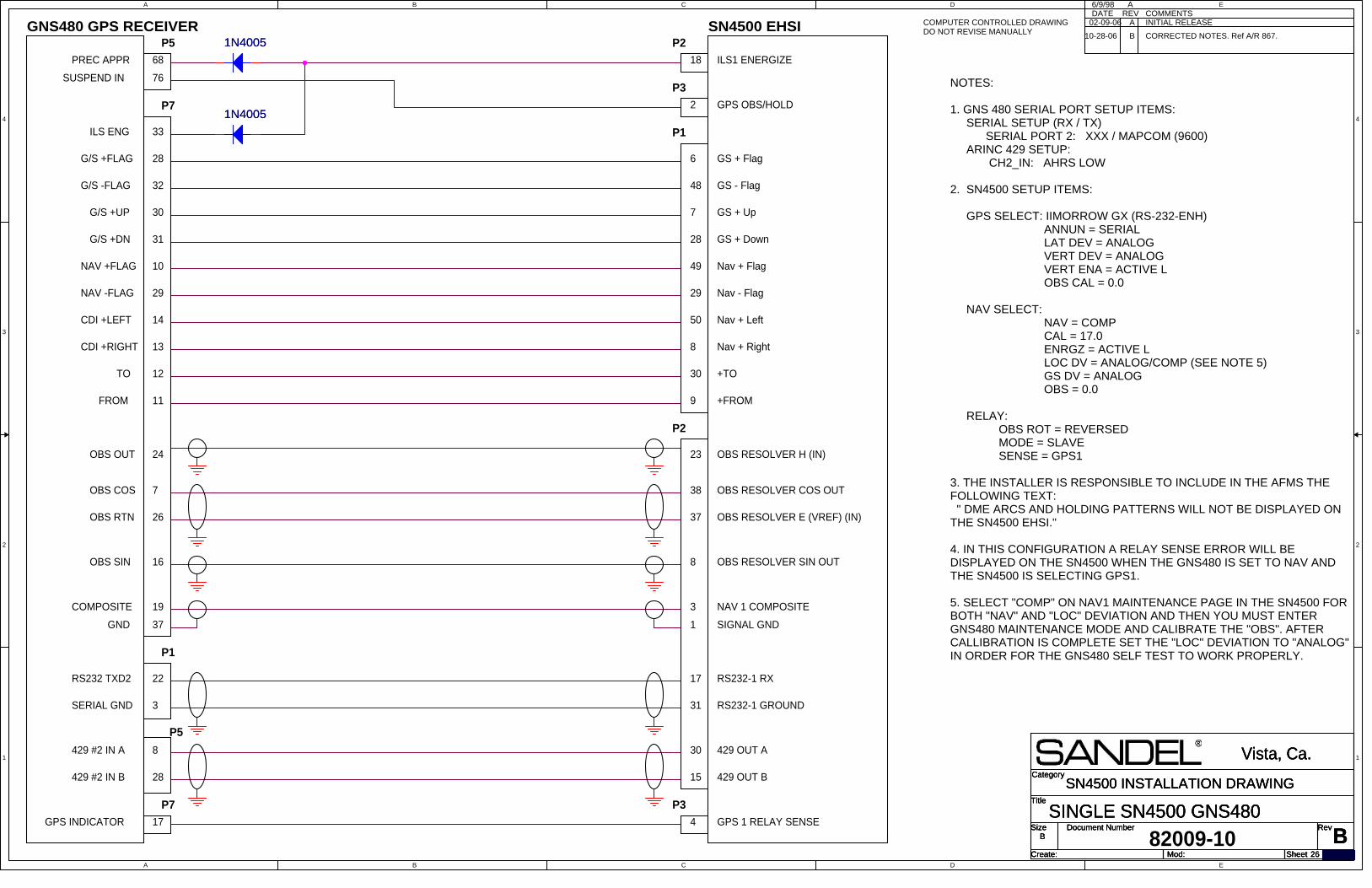
A
A
B
B
C
C
D
D
E
E
4 4
3 3
2 2
1 1
Title
Size Document Number Rev
Create: Sheet of
Category
Mod:
BSINGLE SN4500 GNS480
Vista, Ca.
B
26
SN4500 INSTALLATION DRAWINGTitle
Size Document Number Rev
Create: Sheet of
Category
Mod:
BSINGLE SN4500 GNS480
Vista, Ca.
B
26
SN4500 INSTALLATION DRAWINGTitle
Size Document Number Rev
Create: Sheet of
Category
Mod:
BSINGLE SN4500 GNS480
Vista, Ca.
B
26
SN4500 INSTALLATION DRAWING
A INITIAL RELEASEDATE6/9/98
REVA
COMMENTS
GNS480 GPS RECEIVER
OBS OUT 24
7
OBS RTN
OBS COS
16OBS SIN
26
22
3SERIAL GND
429 #2 IN B
8
RS232 TXD2
429 #2 IN A
P1
NOTES:
1. GNS 480 SERIAL PORT SETUP ITEMS: SERIAL SETUP (RX / TX) SERIAL PORT 2: XXX / MAPCOM (9600) ARINC 429 SETUP: CH2_IN: AHRS LOW
2. SN4500 SETUP ITEMS:
GPS SELECT: IIMORROW GX (RS-232-ENH) ANNUN = SERIAL LAT DEV = ANALOG VERT DEV = ANALOG VERT ENA = ACTIVE L OBS CAL = 0.0 NAV SELECT: NAV = COMP CAL = 17.0 ENRGZ = ACTIVE L LOC DV = ANALOG/COMP (SEE NOTE 5) GS DV = ANALOG OBS = 0.0
RELAY: OBS ROT = REVERSED MODE = SLAVE SENSE = GPS1
3. THE INSTALLER IS RESPONSIBLE TO INCLUDE IN THE AFMS THEFOLLOWING TEXT: " DME ARCS AND HOLDING PATTERNS WILL NOT BE DISPLAYED ONTHE SN4500 EHSI."
4. IN THIS CONFIGURATION A RELAY SENSE ERROR WILL BEDISPLAYED ON THE SN4500 WHEN THE GNS480 IS SET TO NAV ANDTHE SN4500 IS SELECTING GPS1.
5. SELECT "COMP" ON NAV1 MAINTENANCE PAGE IN THE SN4500 FORBOTH "NAV" AND "LOC" DEVIATION AND THEN YOU MUST ENTERGNS480 MAINTENANCE MODE AND CALIBRATE THE "OBS". AFTERCALLIBRATION IS COMPLETE SET THE "LOC" DEVIATION TO "ANALOG"IN ORDER FOR THE GNS480 SELF TEST TO WORK PROPERLY.
P5
PREC APPR
82009-10
NAV +FLAG
NAV -FLAG
CDI +RIGHT
CDI +LEFT
FROM
TO
29
14
13
12
G/S +FLAG
G/S -FLAG
G/S +UP
G/S +DN
P7
68
28
32
30
11
28
31
10
COMPOSITE 19
GND 37
ILS ENG 33
6
ILS1 ENERGIZE
Nav + Left
GS + Up
P1
49
1
SN4500 EHSI
OBS RESOLVER SIN OUT
15
17
30
Nav + Right
GS + Flag
OBS RESOLVER E (VREF) (IN)
3
8
48
RS232-1 RX
37
+TO
18
+FROM
GS - Flag
31
50
8
9
29
429 OUT A
Nav - Flag
P2
7
28
SIGNAL GND
OBS RESOLVER H (IN)
38
30
Nav + Flag
GS + Down
OBS RESOLVER COS OUT
NAV 1 COMPOSITE
23
P2
429 OUT B
RS232-1 GROUND
GPS INDICATOR 17
P3P7
4 GPS 1 RELAY SENSE
GPS OBS/HOLD2
P376SUSPEND IN
P5
COMPUTER CONTROLLED DRAWINGDO NOT REVISE MANUALLY B CORRECTED NOTES. Ref A/R 867.
02-09-06
10-28-06
1N40051N4005
1N40051N4005

A
A
B
B
C
C
D
D
E
E
4 4
3 3
2 2
1 1
Title
Size Document Number Rev
Create: Sheet of
Category
Mod:
C
SINGLE SN4500 SINGLE GNS430/530 GTN6XX/7XX
Vista, Ca.
B
27 29
SN4500 INSTALLATION DRAWINGTitle
Size Document Number Rev
Create: Sheet of
Category
Mod:
C
SINGLE SN4500 SINGLE GNS430/530 GTN6XX/7XX
Vista, Ca.
B
27 29
SN4500 INSTALLATION DRAWINGTitle
Size Document Number Rev
Create: Sheet of
Category
Mod:
C
SINGLE SN4500 SINGLE GNS430/530 GTN6XX/7XX
Vista, Ca.
B
27 29
SN4500 INSTALLATION DRAWING
A INITIAL RELEASEDATE REV COMMENTS
COMPUTER CONTROLLED DRAWINGDO NOT REVISE MANUALLY
THIS 6-WIRE INTERCONNECT PERFORMS THE FOLLOWING
GPS/VLOC AUTOPILOT SWITCHING
COURSE RESOLVER
DEVIATION
TO/FROM
FLAGS
ANNUNCIATORS
MODE SWITCHING
48/50
3/35
Nav 429 In B Port 1/2 23
429 Out B
Nav 429 In A Port 1/2
GPS 429 In B 1/2
17/32
MAIN PORT
33/21
Connection toDesired Pins forunit 1 or 2
GPS 429 Out A
15
VLOC 429 Out A
TO AUTOPILOT, OR SEE SANDEL "FCSDEVIATION (INT RELAY)" DIAGRAM IFADDITIONAL RECEIVERS ARE SWITCHED TOTHE AUTOPILOT.
P4001
GPS 429 In B Port 1/2
24
GPS 429 In A 1/2
SN4500
ANALOG
429 Out A
P2
GPS 429 Out B
31/2
49/51
P4006
Connection to One Port ONLY!(48/49) OR (50/51)(47/66) OR (48/67) for GTN 6XX/7XX
VLOC 429 Out B
47
GPS 429 In A Port 1/2
30
46
GARMIN
48/50
23
P5001
24
49/51
P5006
47
46
GNS 430
GNS 530
82009-10
B CORRECTED NOTES. Ref A/R 867.02-09-0610-28-06
GTN6XX7XXP1004
P1001
23
24
47/48
66/67
9/10
28/29For GTN6XX/7XX - Connection to One Port Only!(9/28) or (10/29)
11-11-13A/R 1378 Garmin GTN6XX/7XX added.Notes updated for GTN6XX/7XX.Drawing title updated for 6XX/7XX.
C
GARMIN SETUP ITEMS SOFTWARE MAIN 4.00 OR LATER MAIN ARINC-429 CONFIGURATION: IN 1: LOW, SANDEL EHSI OUT: LOW, GAMA 429 Graphics w/Int SDI: LNAV 1 (SDI1) SET VNAV LABELS TO ENABLE VOR/LOC/GS ARINC-429 CONFIGURATION: SPD RX: LOW SPD TX: LOW SDI: VOR/ILS 1 (SDI1)
2.
Notes:
GARMIN GTN SETUP:SOFTWARE MAIN 5.00 OR LATERSELECT "EFIS FORMAT 4" FOR THE ARINC 429 INPUTSELECT "HIGH" OR "LOW" SPEED FORMAT 3 FOR THE ARINC GPS 429 OUTSELECT "GAMA FORMAT 3" FOR THE ARINC GPS 429 OUT.SELECT HIGH OR LOW SPEED AS DESIRED.SELECT "LNAV 1" OR "LANAV 2" AS DESIRED.
AS APPROPRIATE SET MAINTENANCE PAGE 7: GPS-1AND/OR PAGE 8:SELECT GNS430 (ARINC), GNS500 (ARINC) or GTN (6XX/7XX)
3.1.
ANNUN SERIALLAT DV SERIALVERT DV SERIALVERT ENA SERIALARINC 429 429 or 429H as neededAPR ACTV ANNUN IN (if Autopilot is interfaced to P2-27)
SET MAINTENANCE PAGE 5: NAV/ILS/DME-1 AND/ORPAGE 6 : NAV/ILS/DME-2 AS FOLLOWS:
4.
NAV 429 FR OR 429H FR AS NEEDEDENRGZ 429 OR 429H AS NEEDEDLOC DV 429 OR 429H AS NEEDEDG/S DV 429 OR 429H AS NEEDED
SELECT ON VOR/LOC/GS CONFIGURATION PAGE:SPEED: LOW OR HIGH AS NEEDED.SDI: VOR/ILS 1 OR VOR/ILS 2 AS DESIRED
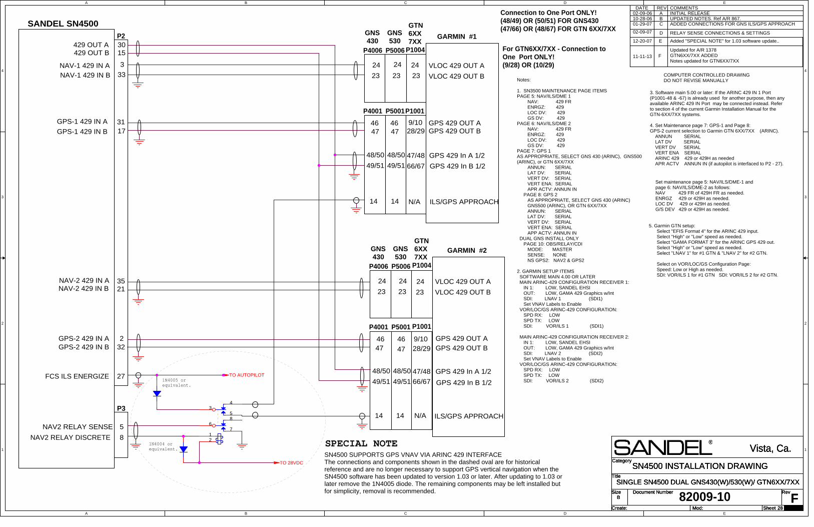
A
A
B
B
C
C
D
D
E
E
4 4
3 3
2 2
1 1
TO AUTOPILOT
TO 28VDC
Title
Size Document Number Rev
Create: Sheet of
Category
Mod:
F
SINGLE SN4500 DUAL GNS430(W)/530(W)/ GTN6XX/7XX
Vista, Ca.
B
28 29
SN4500 INSTALLATION DRAWINGTitle
Size Document Number Rev
Create: Sheet of
Category
Mod:
F
SINGLE SN4500 DUAL GNS430(W)/530(W)/ GTN6XX/7XX
Vista, Ca.
B
28 29
SN4500 INSTALLATION DRAWINGTitle
Size Document Number Rev
Create: Sheet of
Category
Mod:
F
SINGLE SN4500 DUAL GNS430(W)/530(W)/ GTN6XX/7XX
Vista, Ca.
B
28 29
SN4500 INSTALLATION DRAWING
COMMENTSDATEINITIAL RELEASEA
REV
82009-10
COMPUTER CONTROLLED DRAWINGDO NOT REVISE MANUALLY
B UPDATED NOTES. Ref A/R 867.02-09-0610-28-06
NAV-1 429 IN ANAV-1 429 IN B
3
33
14 14 ILS/GPS APPROACH
14 14 ILS/GPS APPROACH
23
47
46
24
GPS 429 OUT B
VLOC 429 OUT A
GPS 429 OUT A
VLOC 429 OUT B
P5001
P5006
23
4746
24
P4001
P4006
49/51
48/50
GNS 430
GNS 530
49/51
48/50 GPS 429 In A 1/2
GPS 429 In B 1/2
For GTN6XX/7XX - Connection toOne Port ONLY!(9/28) OR (10/29)
27FCS ILS ENERGIZE
5
8
P3
NAV2 RELAY SENSE
NAV2 RELAY DISCRETE
23
4746
24
15
21
P2
31
30
17
232
GPS 429 OUT B
VLOC 429 OUT A
GPS 429 OUT A
GARMIN #1
VLOC 429 OUT B
P5001
P5006
35
429 OUT B429 OUT A
GPS-2 429 IN A
GPS-1 429 IN B
GPS-1 429 IN A
NAV-2 429 IN ANAV-2 429 IN B
GPS-2 429 IN B
SANDEL SN4500
23
4746
24
P4001
P4006
49/51
48/50
GNS 430
GNS 530
GARMIN #2
49/51
48/50 GPS 429 In A 1/2
GPS 429 In B 1/2
Connection to One Port ONLY!(48/49) OR (50/51) FOR GNS430(47/66) OR (48/67) FOR GTN 6XX/7XX
01-29-07 ADDED CONNECTIONS FOR GNS ILS/GPS APPROACHC
02-09-07 D RELAY SENSE CONNECTIONS & SETTINGS
1N4004 orequivalent.
1N4005 orequivalent.
SN4500 SUPPORTS GPS VNAV VIA ARINC 429 INTERFACEThe connections and components shown in the dashed oval are for historicalreference and are no longer necessary to support GPS vertical navigation when theSN4500 software has been updated to version 1.03 or later. After updating to 1.03 orlater remove the 1N4005 diode. The remaining components may be left installed butfor simplicity, removal is recommended.
SPECIAL NOTE
12-20-07 E Added "SPECIAL NOTE" for 1.03 software update..
P1004
GTN6XX7XX
23
24
P1001
9/1028/29
47/48
66/67
N/A
23
24
9/1028/29
47/48
66/67
N/A
Notes:
1. SN3500 MAINTENANCE PAGE ITEMSPAGE 5: NAV/ILS/DME 1 NAV: 429 FR ENRGZ: 429 LOC DV: 429 GS DV: 429PAGE 6: NAV/ILS/DME 2 NAV: 429 FR ENRGZ: 429 LOC DV: 429 GS DV: 429PAGE 7: GPS 1AS APPROPRIATE, SELECT GNS 430 (ARINC), GNS500(ARINC), or GTN 6XX/7XX ANNUN: SERIAL LAT DV: SERIAL VERT DV: SERIAL VERT ENA: SERIAL APR ACTV: ANNUN IN PAGE 8: GPS 2 AS APPROPRIATE, SELECT GNS 430 (ARINC) GNS500 (ARINC), OR GTN 6XX/7XX ANNUN: SERIAL LAT DV: SERIAL VERT DV: SERIAL VERT ENA: SERIAL APP ACTV: ANNUN IN DUAL GNS INSTALL ONLY PAGE 10: OBS/RELAY/CDI MODE: MASTER SENSE: NONE NS GPS2: NAV2 & GPS2
2. GARMIN SETUP ITEMS SOFTWARE MAIN 4.00 OR LATER MAIN ARINC-429 CONFIGURATION RECEIVER 1: IN 1: LOW, SANDEL EHSI OUT: LOW, GAMA 429 Graphics w/Int SDI: LNAV 1 (SDI1) Set VNAV Labels to Enable VOR/LOC/GS ARINC-429 CONFIGURATION: SPD RX: LOW SPD TX: LOW SDI: VOR/ILS 1 (SDI1)
MAIN ARINC-429 CONFIGURATION RECEIVER 2: IN 1: LOW, SANDEL EHSI OUT: LOW, GAMA 429 Graphics w/Int SDI: LNAV 2 (SDI2) Set VNAV Labels to Enable VOR/LOC/GS ARINC-429 CONFIGURATION: SPD RX: LOW SPD TX: LOW SDI: VOR/ILS 2 (SDI2)
3. Software main 5.00 or later: If the ARINC 429 IN 1 Port(P1001-48 & -67) is already used for another purpose, then anyavailable ARINC 429 IN Port may be connected instead. Referto section 4 of the current Garmin Installation Manual for theGTN-6XX/7XX systems.
4. Set Maintenance page 7: GPS-1 and Page 8:GPS-2 current selection to Garmin GTN 6XX/7XX (ARINC). ANNUN SERIAL LAT DV SERIAL VERT DV SERIAL VERT ENA SERIAL ARINC 429 429 or 429H as needed APR ACTV ANNUN IN (if autopilot is interfaced to P2 - 27).
Set maintenance page 5: NAV/ILS/DME-1 and page 6: NAV/ILS/DME-2 as follows: NAV 429 FR of 429H FR as needed. ENRGZ 429 or 429H as needed. LOC DV 429 or 429H as needed. G/S DEV 429 or 429H as needed.
5. Garmin GTN setup: Select "EFIS Format 4" for the ARINC 429 input. Select "High" or "Low" speed as needed. Select "GAMA FORMAT 3" for the ARINC GPS 429 out. Select "High" or "Low" speed as needed. Select "LNAV 1" for #1 GTN & "LNAV 2" for #2 GTN.
Select on VOR/LOC/GS Configuration Page: Speed: Low or High as needed. SDI: VOR/ILS 1 for #1 GTN SDI: VOR/ILS 2 for #2 GTN.
11-11-13 FUpdated for A/R 1378GTN6XX/7XX ADDEDNotes updated for GTN6XX/7XX
GTN6XX7XX
P1004
P1001
34
5
68
712
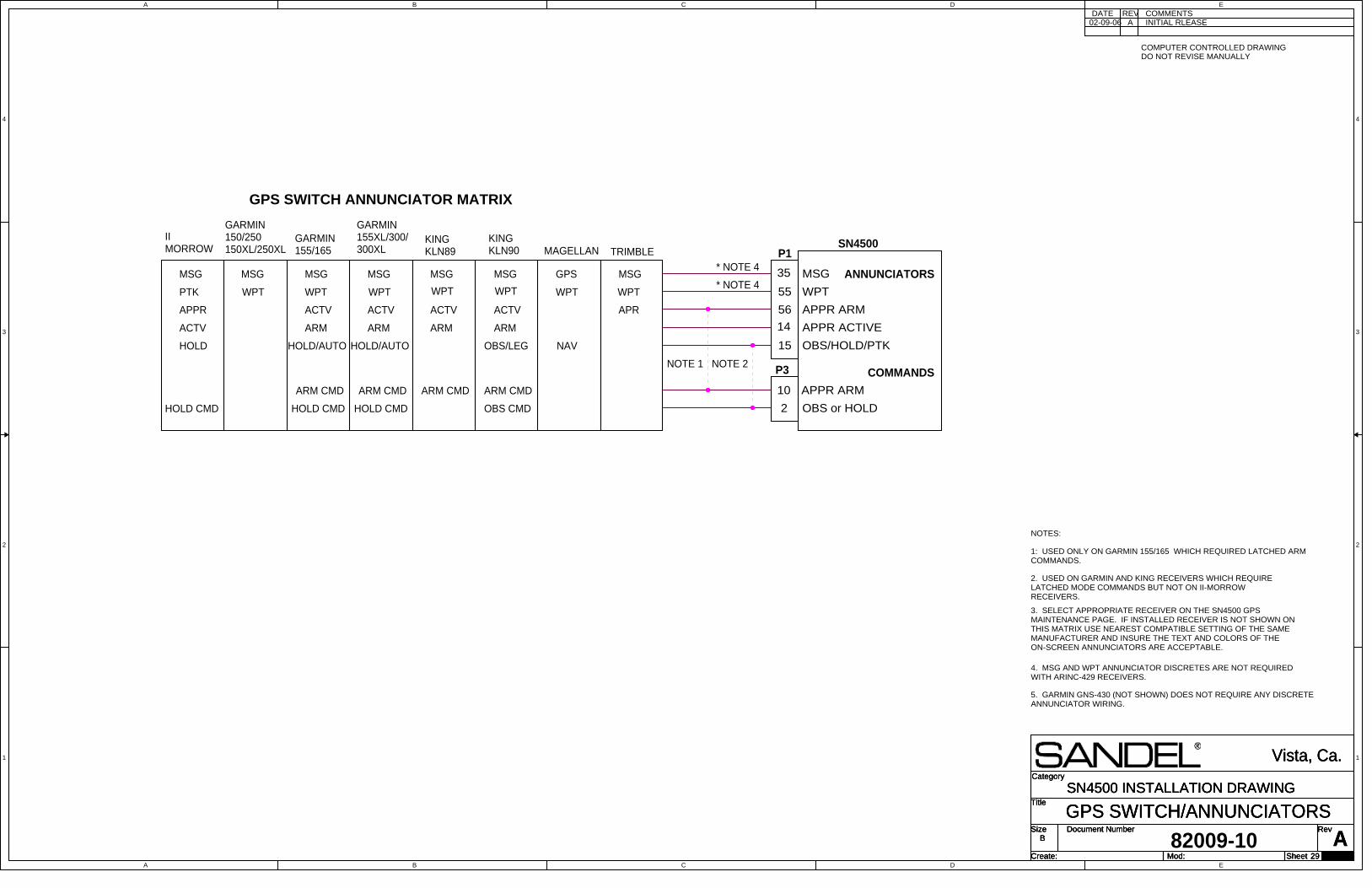
A
A
B
B
C
C
D
D
E
E
4 4
3 3
2 2
1 1
Title
Size Document Number Rev
Create: Sheet of
Category
Mod:
AGPS SWITCH/ANNUNCIATORS
Vista, Ca.
B
29 29
SN4500 INSTALLATION DRAWINGTitle
Size Document Number Rev
Create: Sheet of
Category
Mod:
AGPS SWITCH/ANNUNCIATORS
Vista, Ca.
B
29 29
SN4500 INSTALLATION DRAWINGTitle
Size Document Number Rev
Create: Sheet of
Category
Mod:
AGPS SWITCH/ANNUNCIATORS
Vista, Ca.
B
29 29
SN4500 INSTALLATION DRAWING
MSG
PTK
ACTV
APPR
HOLD
IIMORROW
GARMIN150/250150XL/250XL
GARMIN155/165
HOLD/AUTO HOLD/AUTO
GARMIN155XL/300/300XL
KINGKLN89
KINGKLN90
OBS/LEG
WPT
ARM
MSG
ACTV
MAGELLAN
GPS
WPT
NAV
TRIMBLE
MSG
WPT
APR
35
55
14
56
15
P1SN4500
MSG
WPT
APPR ARM
APPR ACTIVE
OBS/HOLD/PTK
P3
10 APPR ARM
2 OBS or HOLD
ARM CMD
NOTE 1
1: USED ONLY ON GARMIN 155/165 WHICH REQUIRED LATCHED ARMCOMMANDS.
OBS CMD
ARM CMD
HOLD CMD HOLD CMDHOLD CMD
NOTE 2
2. USED ON GARMIN AND KING RECEIVERS WHICH REQUIRELATCHED MODE COMMANDS BUT NOT ON II-MORROWRECEIVERS.
GPS SWITCH ANNUNCIATOR MATRIX
NOTES:
3. SELECT APPROPRIATE RECEIVER ON THE SN4500 GPSMAINTENANCE PAGE. IF INSTALLED RECEIVER IS NOT SHOWN ONTHIS MATRIX USE NEAREST COMPATIBLE SETTING OF THE SAMEMANUFACTURER AND INSURE THE TEXT AND COLORS OF THEON-SCREEN ANNUNCIATORS ARE ACCEPTABLE.
ANNUNCIATORS
COMMANDS
ARM CMDARM CMD
* NOTE 4
* NOTE 4
4. MSG AND WPT ANNUNCIATOR DISCRETES ARE NOT REQUIREDWITH ARINC-429 RECEIVERS.
COMMENTSDATEA
REVINITIAL RLEASE
COMPUTER CONTROLLED DRAWINGDO NOT REVISE MANUALLY
5. GARMIN GNS-430 (NOT SHOWN) DOES NOT REQUIRE ANY DISCRETEANNUNCIATOR WIRING.
WPT
MSG
WPT
ARM
MSG
ACTV
WPT
ARM
MSG
ACTV
WPT
ARM
MSG
ACTV
82009-10
02-09-06

A
A
B
B
C
C
D
D
E
E
4 4
3 3
2 2
1 1
Title
Size Document Number Rev
Create: Sheet of
Category
Mod:
BRESOLVER INTERCONNECT
Vista, Ca.
B
30 29
SN4500 INSTALLATION DRAWINGTitle
Size Document Number Rev
Create: Sheet of
Category
Mod:
BRESOLVER INTERCONNECT
Vista, Ca.
B
30 29
SN4500 INSTALLATION DRAWINGTitle
Size Document Number Rev
Create: Sheet of
Category
Mod:
BRESOLVER INTERCONNECT
Vista, Ca.
B
30 29
SN4500 INSTALLATION DRAWING
A INITIAL RELEASEDATE REV COMMENTS
NOTES:
1. THE SN4500 REQUIRES DC FLAG SIGNALS. SOME VERY OLD RECEIVERDESIGNS OUTPUT UNSMOOTHED DC DUE TO A LACK OF FILTERING CAPACITORS. THE SN4500 WILL SHOW UNSTABLE FLAG OPERATION UNLESS SMOOTHINGCAPACITORS ARE ADDED AS SHOWN. THE CAPACITORS CAN BE MOUNTED ON ATERMINAL BLOCK NEAR THE RECEIVERS. CONSULT THE RECEIVER SERVICEMANUAL SCHEMATICS AS REQUIRED.
2. FOR ARINC NAV RECEIVER USING 400HZ DIFFERENTIAL RESOLVER:
a) THE NAV RCVR AND SN4500 MUST BE ON THE SAME INVERTER. b) ON OBS/RELAY/CDI MAINTENANCE PAGE SET OBS TYPE TO "DIFF A".
COMPUTER CONTROLLED DRAWINGDO NOT REVISE MANUALLY
B
F
L
M
C
RESOLVER DRIVE20
3
22
21
2
13
5
4
K
I
COMMON NAV CONVERTER INTERCONNECTS
ROTOR RET
ROTOR DRIVE
SIN RET
COS RET
STATOR REF
10
B
D
J
H
2
11
10
C
3 8 OBS RESOLVER SIN OUT
OBS RESOLVER H (IN)
OBS RESOLVER COS OUT
37
38
OBS RESOLVER VREF (IN)
P2SN4500
23
19
21
24
25
20
41
48
46
44
47
F
12
R
11
X
27
28
12
11
29
KN
74
3
2
1
5
4
1C
70
7P
89
2
y
v
JJ
B
KK
KN
72
J72
1
KN
77
J10
1
KN
S80
J10
1
KN
S81
J81
1
KX
165
J90
1
AR
C4
45
KN
R6
30
P6
03
1
VIR
30
MP
2
VIR
35
1
NAV -FLAG
+FROM
GS +FLAG
GS -FLAG
+TO
NAV +FLAG
NAV RECEIVER
United LXF10VB222M or equivalent.
TO SN4500
CONNECTION TO OLDER RECEIVERS SUCH AS COLLINS 51R8, 51RV-1,KING KNR660 AND SIMILAR RECEIVERS. SEE NOTE 1.
42
OBS 'B' DEV 8
400HZ DIFF RES. SIN IN
P2
OBS 'E' COS OUT
SN4500
ARINC NAV RECEIVERS KNR634 AND COLLINS VIR-30A(FOR VIR-30M SEE ABOVE) SEE NOTE 2.
38
43
P2
OBS 'F' SIN OUT
OBS 'A' TO/FROM
46
VIR-30A
47 400HZ DIFF RES. COS IN
400HZ DIFF RES. SIN OUT
400HZ DIFF RES. COS OUT
MK
12
D/E
P1
03
5
8.
10
2
B
J
22
24
37
21
P6342KNR634
32
11
P1
82009-10
B UPDATED DIFF RESOLVER PIN NUMBERS. Ref A/R 867.
02-09-0610-28-06
+
2200uF
+
2200uF
+2200uF
+2200uF
+
2200uF
+
2200uF
+
2200uF
+
2200uF
220 OHM220 OHM
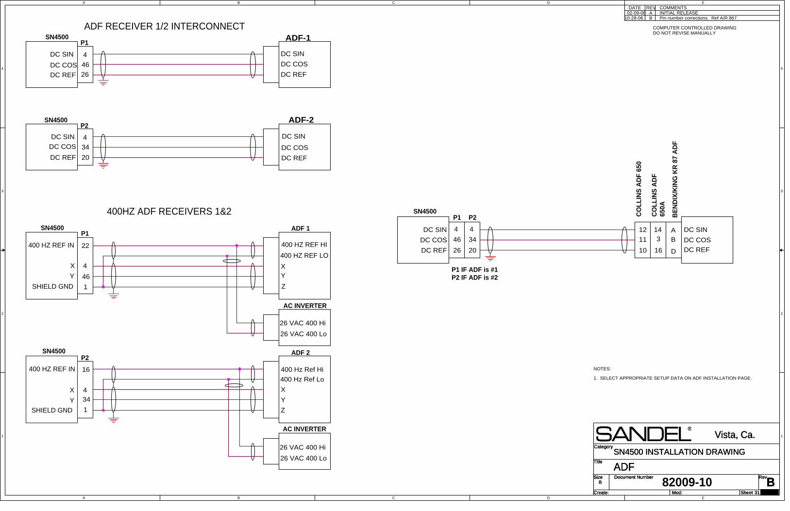
A
A
B
B
C
C
D
D
E
E
4 4
3 3
2 2
1 1
Title
Size Document Number Rev
Create: Sheet of
Category
Mod:
BADF
Vista, Ca.
B
31 29
SN4500 INSTALLATION DRAWINGTitle
Size Document Number Rev
Create: Sheet of
Category
Mod:
BADF
Vista, Ca.
B
31 29
SN4500 INSTALLATION DRAWINGTitle
Size Document Number Rev
Create: Sheet of
Category
Mod:
BADF
Vista, Ca.
B
31 29
SN4500 INSTALLATION DRAWING
NOTES:
1. SELECT APPROPRIATE SETUP DATA ON ADF INSTALLATION PAGE.
ADF-2
400HZ ADF RECEIVERS 1&2
ADF RECEIVER 1/2 INTERCONNECT
COMMENTSDATEINITIAL RELEASEA
REV
COMPUTER CONTROLLED DRAWINGDO NOT REVISE MANUALLY
34
SN4500P2
DC COS
DC SIN
20DC REF DC REF
11
DC SIN
CO
LL
INS
AD
F 6
50
DC COS
10
12
CO
LL
INS
AD
F65
0A
46
SN4500P1
4
DC COS
DC SIN
26DC REF DC REF
DC SIN
DC COS
34
SN4500P2
4DC COS
DC SIN
20DC REF DC REF
DC SIN
DC COS
ADF-1
BE
ND
IX/K
ING
KR
87
AD
F
Y
X
Z
SN4500
4
YX
46
ADF 1P1
22
AC INVERTER
26 VAC 400 Hi
26 VAC 400 Lo
Y
X
Z
SN4500
4
Y
X
34
ADF 2P2
400 Hz Ref Hi
400 Hz Ref Lo
16
AC INVERTER
26 VAC 400 Hi
26 VAC 400 Lo
3
16
14
B
D
A
1SHIELD GND
400 HZ REF IN 400 HZ REF HI
400 HZ REF LO
400 HZ REF IN
1SHIELD GND
4
82009-10
B Pin number corrections. Ref A/R 867.
46
P1
26
4
P1 IF ADF is #1P2 IF ADF is #2
02-09-0610-28-06

A
A
B
B
C
C
D
D
E
E
4 4
3 3
2 2
1 1
Title
Size Document Number Rev
Create: Sheet of
Category
Mod:A
MARKER BEACON
Vista, Ca.
B
32 29
SN4500 INSTALLATION DRAWINGTitle
Size Document Number Rev
Create: Sheet of
Category
Mod:A
MARKER BEACON
Vista, Ca.
B
32 29
SN4500 INSTALLATION DRAWINGTitle
Size Document Number Rev
Create: Sheet of
Category
Mod:A
MARKER BEACON
Vista, Ca.
B
32 29
SN4500 INSTALLATION DRAWING
1. THESE LOAD RESISTORS ARE REQUIRED FOR PS ENGINEERING MARKERRECEIVERS. RECOMMENDED FOR OTHER RECEIVERS TO PREVENT FAILUREOF THE SN4500 INDICATION IF THE ASSOCIATED MARKER LIGHT BULB FAILS.
NOTES:
2. SET MARKERS TO ACTIVE H OR ACTIVE L ON ADF1/ADF2/MKRMAINTENANCE PAGE
COMMENTSDATE REV
DO NOT REVISE MANUALLYCOMPUTER CONTROLLED DRAWING
SANDEL SN4500P1
12
33
53
OM
MM
IM
MARKER RECEIVER
OM
MM
IM
LAMP COM
NOTE 1
EXTERNAL MARKERLAMPS IFINSTALLED
NOTE 2
(THESE LOAD RESISTORS ARE REQUIRED FORPS ENGINEERING MARKER RECEIVERS)
OM
SANDEL SN4500
53
NOTE 2
MARKER RECEIVER
LAMP COM
33
IMIM
12
MMMM
P1
OM
KING KR22
EXTERNAL MARKERLAMPS IF INSTALLED
82009-10
A INITIAL RELEASE02-09-06
47
0
47
0
47
0
47
0
47
0
47
0
1.2
K
1.2
K

A
A
B
B
C
C
D
D
E
E
4 4
3 3
2 2
1 1
Title
Size Document Number Rev
Create: Sheet of
Category
Mod:C
DME, KING SERIAL AND ANALOG
Vista, Ca.
B
33 29
SN4500 INSTALLATION DRAWINGTitle
Size Document Number Rev
Create: Sheet of
Category
Mod:C
DME, KING SERIAL AND ANALOG
Vista, Ca.
B
33 29
SN4500 INSTALLATION DRAWINGTitle
Size Document Number Rev
Create: Sheet of
Category
Mod:C
DME, KING SERIAL AND ANALOG
Vista, Ca.
B
33 29
SN4500 INSTALLATION DRAWING
SINGLE KING SERIAL DIGITAL DME USING KDI572(ANY KING SERIAL DME PERMISSABLE)
NOTES:
1. IN A SINGLE DME CONFIGURATION THE SN4500DETECTS BOTH DME HOLD AND NAV-1/NAV-2ASSIGNMENT. WHEN NAV-2 IS CHANNELED THEDME READOUT WILL ASSOCIATE WITH THEBEARING POINTER NAV-2 SELECTION. IF THE DMEIS NOT ASSIGNABLE LEAVE THE CORRESPONDINGPIN UNCONNECTED.SET DME TO LO FR DME1 ON NAV/ILS/DME 2MAINTENANCE PAGE TO ENABLE NAV2 DMEDISPLAY.
2. IN A DUAL DME CONFIGURATION THE SN4500CAN ONLY DETECT DME HOLD. IT ALWAYSASSOCIATES DME-1 WITH NAV-1 AND DME-2 WITHNAV-2.
3. THE SN4500 WILL SUPPORT REMOTE DISPLAYOF KN62/64 DME'S. CONNECT AS SHOWN, TAKING"DME REQ" FROM REAR CONNECTOR PIN-N. THEKN62/64 DO NOT HAVE A HOLD OUTPUTTHEREFORE NO HOLD ANNUNCIATION ISPOSSIBLE.
COMMENTSDATE
INITIAL RELEASEA
REV
COMPUTER CONTROLLED DRAWINGDO NOT REVISE MANUALLY
KN
63
Data Buss
Clock Buss
DME Request D
F
6 Data Buss6
DME Request
SANDEL SN4500
Clock Buss
2236
P2
DME Request 15
12
11
DME 1 Hold7
NAV 2 Common 49
2DME Hold
DME Hold E
KDI 572DME
Clock Buss
Data Buss
RNAV Request
DME Common
Clock Buss
Data Buss
NAV 2
Data Buss
RNAV Request
Clock Buss
DME Common
52 DME 2 Hold
17RNAV Request
NAV 1 Common 48
NAV 1
Data Buss
Clock BussData Buss6
DME Request
SANDEL SN4500
Clock Buss
22
36
P2
DME Common
P1
RNAV Request
DME Common
Clock Buss
Data Buss
NAV 2
Data Buss
RNAV Request
Clock Buss
DME Common
52 DME 2 Hold
NAV 1C
L
14
13
RNAV Request
DME Request N
DME 1 or 2
Nav 2
Nav 1
DME REQ22
NOTE 2
36
7
6 DATA
DMEHOLD
DME1
DME1 HOLD
SANDEL SN4500
CLK
P2
DUAL KING SERIAL DIGITAL DME'S.
CLK
DME REQ
DATA
DME REQ10
NOTE 2
31
52
51
DATA
DMEHOLD
DME2
DME2 HOLD
CLKCLK
DATA
SINGLE KING SERIAL DIGITAL DME WITH SELF CONTAINED CONTROLLER(KN64 SHOWN FOR REFERENCE, KN62/KN62A PERMISSABLE)
KN 64 DME(NOTE 3)
P1
(NOTE 1)
(NOTE 1)
DME REQ
9
8
2412
KD
M70
6
P1
82009-10
ANALOG DME
DME1 HOLD
DMEHOLDRELAY
P2
DME ANALOG +
DME ANALOG VALID
SANDEL SN4500
6
36
ANALOG DME
DME ANALOG -
40MV/MILE
SIGNAL COM
VALID 6
P3
7
P2
B FORMAT. Ref A/R 867.
02-09-06
10-28-06
11-17-06 C Corrected label on P1-52 from DME 1 Hold to DME 2Hold. Ref A/R 950.

A
A
B
B
C
C
D
D
E
E
4 4
3 3
2 2
1 1
Title
Size Document Number Rev
Create: Sheet of
Category
Mod:
BDME: ARINC 568
Vista, Ca.
B
34 29
SN4500 INSTALLATION DRAWINGTitle
Size Document Number Rev
Create: Sheet of
Category
Mod:
BDME: ARINC 568
Vista, Ca.
B
34 29
SN4500 INSTALLATION DRAWINGTitle
Size Document Number Rev
Create: Sheet of
Category
Mod:
BDME: ARINC 568
Vista, Ca.
B
34 29
SN4500 INSTALLATION DRAWING
SINGLE ARINC 568 DME. COLLINS DME-40SHOWN FOR REFERENCE.
1. IN A SINGLE DME CONFIGURATION THE SN4500 DETECTS BOTH DMEHOLD AND NAV-1/NAV-2 ASSIGNMENT FROM THE INSTALLED SWITCHINGRELAYS. WHEN NAV-2 IS CHANNELED THE DME READOUT WILL ASSOCIATEWITH THE BEARING POINTER NAV-2 SELECTION. IF THE DME IS NOTASSIGNABLE LEAVE THE CORRESPONDING PIN UNCONNECTED.SET DME TO LO FR DME1 ON NAV/ILS/DME 2 MAINTENANCE PAGE TOENABLE NAV2 DME DISPLAY.
2. IN A DUAL DME CONFIGURATION THE SN4500 CAN ONLY DETECT DMEHOLD. IT ALWAYS ASSOCIATES DME-1 WITH NAV-1 AND DME-2 WITHNAV-2.
NOTES:NOTESNOTESNOTES
COMMENTSDATE REV
COMPUTER CONTROLLED DRAWINGDO NOT REVISE MANUALLY
SYNC22
36
7
6 DATA
DME1 HOLD
SANDEL SN4500
CLK
P2
CLK
SYNC
DATA
52
DME-40
DME1 HOLD RELAY
DME NAV-2 RELAY NOTE 1
SYNC22
36
7
6 DATA
DME1 HOLD
SANDEL SN4500
CLK
P2
CLK
SYNC
DATA
DME-40
DME1 HOLD RELAY
10
CLK CLK51
SYNC
31
SYNC
DATA DATA
52DME2 HOLD RELAY DME2 HOLDNOTE 1
P1
DUAL ARINC 568 DME'S. COLLINS DME-40SHOWN FOR REFERENCE
P1
NO. 1
NO. 2
82009-10
INITIAL RELEASEA02-09-06
DME2 HOLD
B11-17-06 Corrected label on P1-52 from DME 1 Hold toDME 2 Hold. Ref A/R 950.
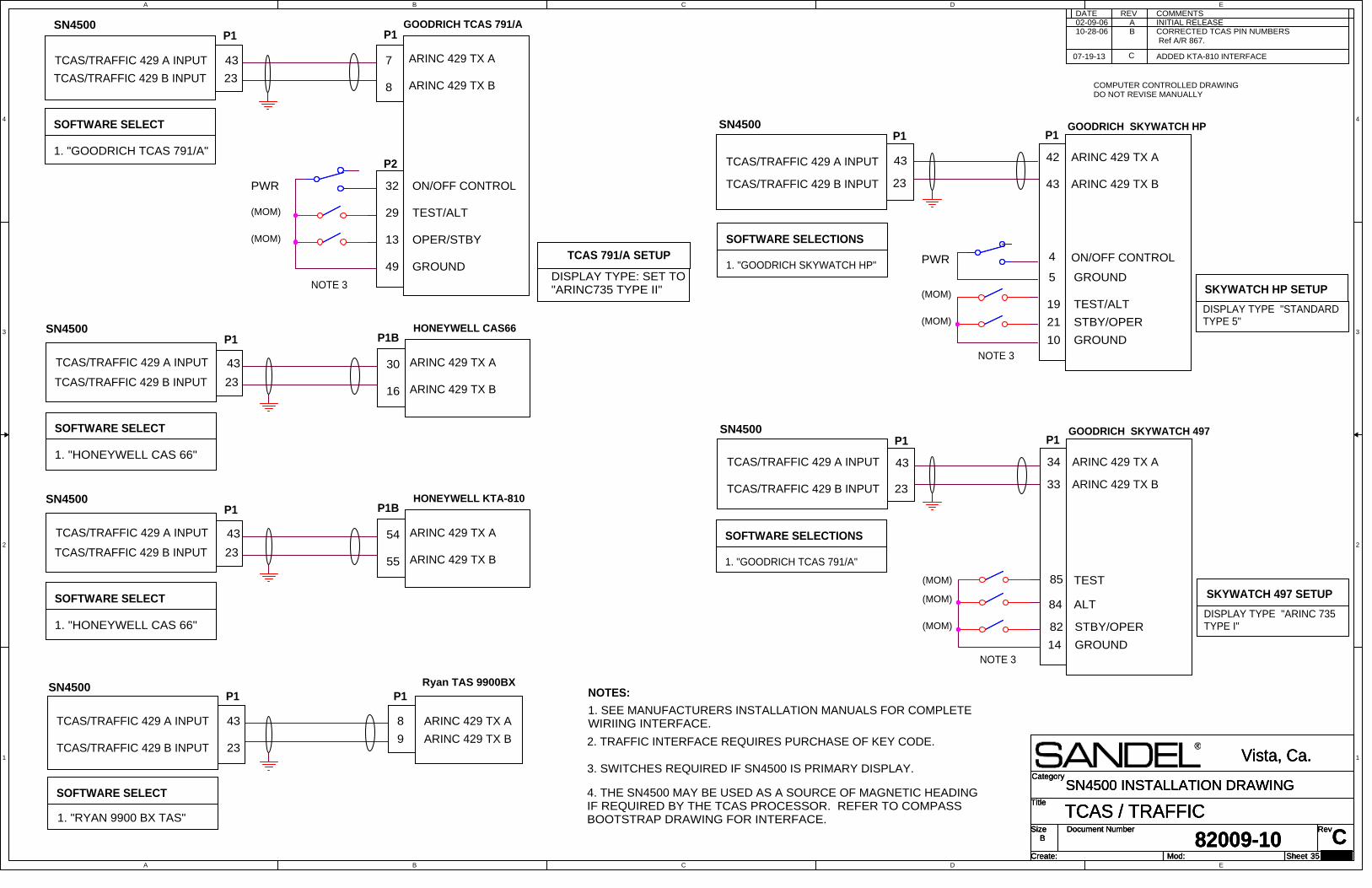
A
A
B
B
C
C
D
D
E
E
4 4
3 3
2 2
1 1
Title
Size Document Number Rev
Create: Sheet of
Category
Mod:
82009-10 CTCAS / TRAFFIC
Vista, Ca.
B
35
SN4500 INSTALLATION DRAWINGTitle
Size Document Number Rev
Create: Sheet of
Category
Mod:
82009-10 CTCAS / TRAFFIC
Vista, Ca.
B
35
SN4500 INSTALLATION DRAWINGTitle
Size Document Number Rev
Create: Sheet of
Category
Mod:
82009-10 CTCAS / TRAFFIC
Vista, Ca.
B
35
SN4500 INSTALLATION DRAWING
COMMENTSA
DATEINITIAL RELEASE
TCAS/TRAFFIC 429 A INPUT
8
7
GOODRICH TCAS 791/AP1
23
43 ARINC 429 TX A
ARINC 429 TX BTCAS/TRAFFIC 429 B INPUT
13
TEST/ALT
OPER/STBY
SOFTWARE SELECT
1. "GOODRICH TCAS 791/A"
29
49 GROUND
ON/OFF CONTROL32
TCAS 791/A SETUP
DISPLAY TYPE: SET TO"ARINC735 TYPE II"
P1
1. SEE MANUFACTURERS INSTALLATION MANUALS FOR COMPLETEWIRIING INTERFACE.
NOTES:
P2
TCAS/TRAFFIC 429 A INPUT
16
30
HONEYWELL CAS66P1
23
43 ARINC 429 TX A
ARINC 429 TX BTCAS/TRAFFIC 429 B INPUT
SOFTWARE SELECT
1. "HONEYWELL CAS 66"
P1B
SN4500
SN4500
PWR
(MOM)
(MOM)
ARINC 429 TX A
1. "RYAN 9900 BX TAS"
SN4500 Ryan TAS 9900BX
9
43 8
SOFTWARE SELECT
TCAS/TRAFFIC 429 A INPUT
COMPUTER CONTROLLED DRAWINGDO NOT REVISE MANUALLY
23TCAS/TRAFFIC 429 B INPUT
P1 P1
ARINC 429 TX B
DISPLAY TYPE "STANDARDTYPE 5"
GOODRICH SKYWATCH HP
GROUND
43
4
SN4500
SKYWATCH HP SETUP(MOM)
(MOM)
23 ARINC 429 TX B
ARINC 429 TX A
TCAS/TRAFFIC 429 B INPUT
SOFTWARE SELECTIONS
21
PWR
TCAS/TRAFFIC 429 A INPUT
1. "GOODRICH SKYWATCH HP"
42
19 TEST/ALT
P1
GROUND
5
ON/OFF CONTROL
10
P1
STBY/OPER
43
1. "GOODRICH TCAS 791/A"
ARINC 429 TX B
STBY/OPER
ALT
SOFTWARE SELECTIONS
23
GOODRICH SKYWATCH 497
84
TCAS/TRAFFIC 429 B INPUT
85
43TCAS/TRAFFIC 429 A INPUT
(MOM)DISPLAY TYPE "ARINC 735TYPE I"
ARINC 429 TX A
(MOM)
GROUND
(MOM)
P1SN4500
TEST
34
33
P1
82
14
SKYWATCH 497 SETUP
NOTE 3
NOTE 3
NOTE 3
3. SWITCHES REQUIRED IF SN4500 IS PRIMARY DISPLAY.
4. THE SN4500 MAY BE USED AS A SOURCE OF MAGNETIC HEADINGIF REQUIRED BY THE TCAS PROCESSOR. REFER TO COMPASSBOOTSTRAP DRAWING FOR INTERFACE.
REV
2. TRAFFIC INTERFACE REQUIRES PURCHASE OF KEY CODE.
B CORRECTED TCAS PIN NUMBERS Ref A/R 867.
02-09-0610-28-06
TCAS/TRAFFIC 429 A INPUT
55
54
HONEYWELL KTA-810P1
23
43 ARINC 429 TX A
ARINC 429 TX BTCAS/TRAFFIC 429 B INPUT
SOFTWARE SELECT
1. "HONEYWELL CAS 66"
P1BSN4500
C07-19-13 ADDED KTA-810 INTERFACE
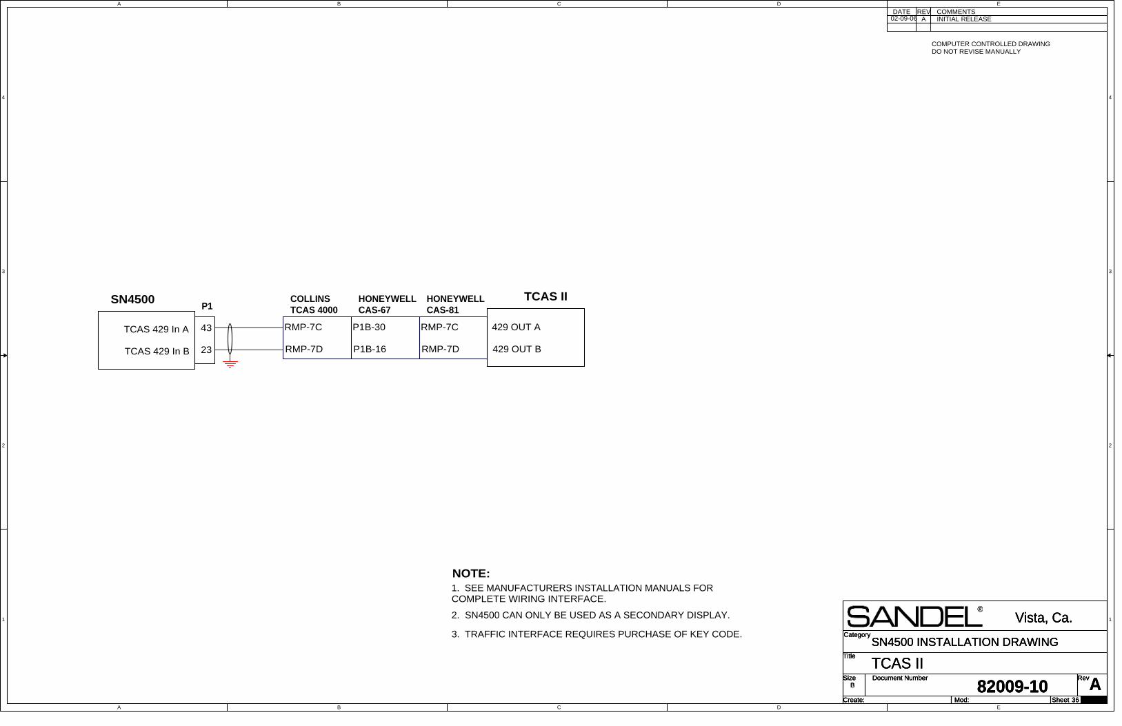
A
A
B
B
C
C
D
D
E
E
4 4
3 3
2 2
1 1
Title
Size Document Number Rev
Create: Sheet of
Category
Mod:
82009-10 ATCAS II
Vista, Ca.
B
36
SN4500 INSTALLATION DRAWINGTitle
Size Document Number Rev
Create: Sheet of
Category
Mod:
82009-10 ATCAS II
Vista, Ca.
B
36
SN4500 INSTALLATION DRAWINGTitle
Size Document Number Rev
Create: Sheet of
Category
Mod:
82009-10 ATCAS II
Vista, Ca.
B
36
SN4500 INSTALLATION DRAWING
COMMENTSA
REVDATEINITIAL RELEASE
COMPUTER CONTROLLED DRAWINGDO NOT REVISE MANUALLY
NOTE:1. SEE MANUFACTURERS INSTALLATION MANUALS FORCOMPLETE WIRING INTERFACE.
2. SN4500 CAN ONLY BE USED AS A SECONDARY DISPLAY.
SN4500P1
23
TCAS 429 In A
TCAS 429 In B
43
RMP-7D
RMP-7C
COLLINSTCAS 4000
3. TRAFFIC INTERFACE REQUIRES PURCHASE OF KEY CODE.
P1B-16
P1B-30
HONEYWELLCAS-67
RMP-7C
RMP-7D
HONEYWELLCAS-81
TCAS II
429 OUT A
429 OUT B
02-09-06
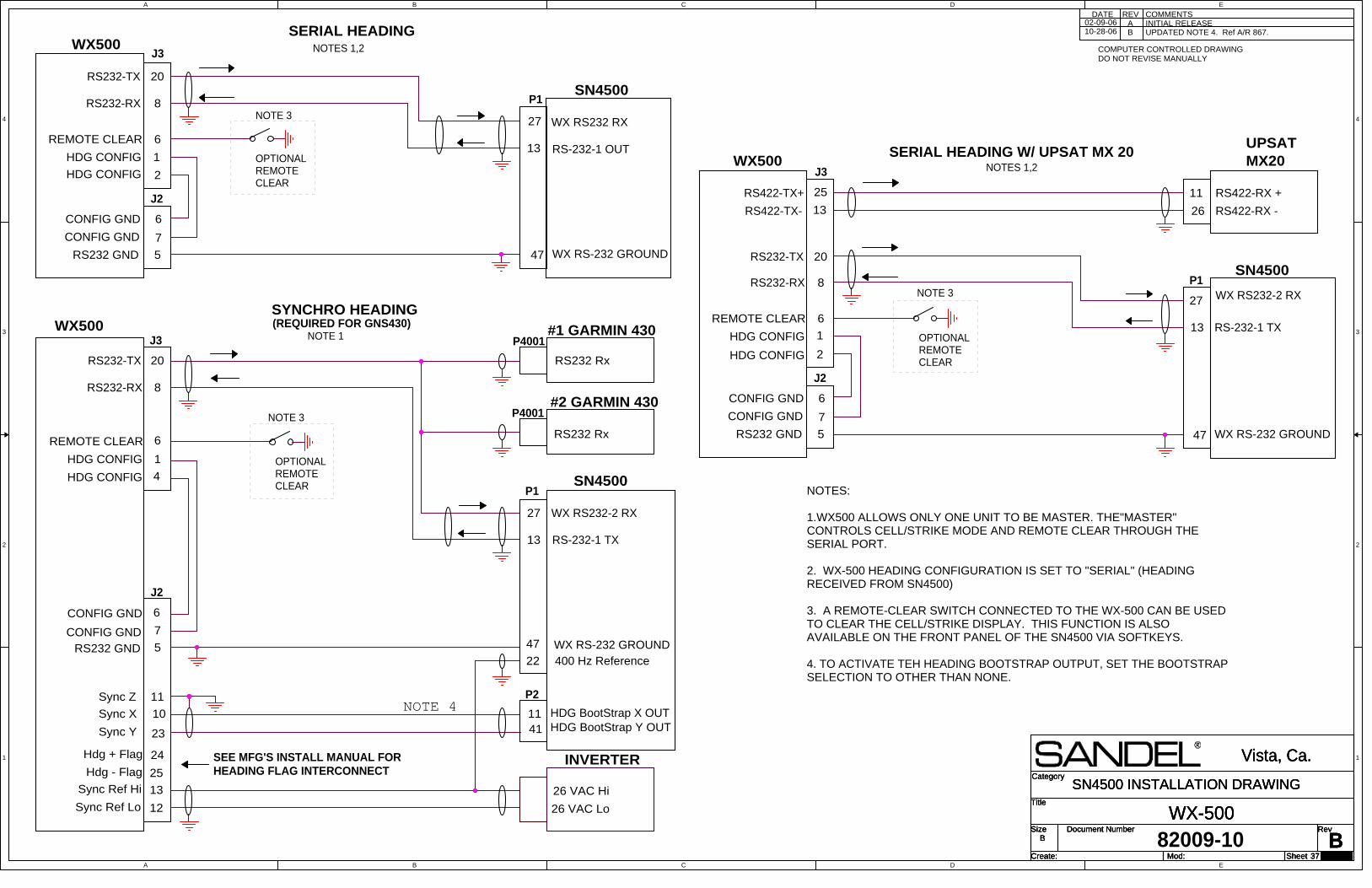
A
A
B
B
C
C
D
D
E
E
4 4
3 3
2 2
1 1
Title
Size Document Number Rev
Create: Sheet of
Category
Mod:B
WX-500
Vista, Ca.
B
37 29
SN4500 INSTALLATION DRAWINGTitle
Size Document Number Rev
Create: Sheet of
Category
Mod:B
WX-500
Vista, Ca.
B
37 29
SN4500 INSTALLATION DRAWINGTitle
Size Document Number Rev
Create: Sheet of
Category
Mod:B
WX-500
Vista, Ca.
B
37 29
SN4500 INSTALLATION DRAWING
INITIAL RELEASEDATE REV COMMENTS
NOTES:
1.WX500 ALLOWS ONLY ONE UNIT TO BE MASTER. THE"MASTER"CONTROLS CELL/STRIKE MODE AND REMOTE CLEAR THROUGH THESERIAL PORT.
2. WX-500 HEADING CONFIGURATION IS SET TO "SERIAL" (HEADINGRECEIVED FROM SN4500)
3. A REMOTE-CLEAR SWITCH CONNECTED TO THE WX-500 CAN BE USEDTO CLEAR THE CELL/STRIKE DISPLAY. THIS FUNCTION IS ALSOAVAILABLE ON THE FRONT PANEL OF THE SN4500 VIA SOFTKEYS.
4. TO ACTIVATE TEH HEADING BOOTSTRAP OUTPUT, SET THE BOOTSTRAPSELECTION TO OTHER THAN NONE.
27
RS232-TX
P1
RS232-RX
13
J3
20
8
RS-232-1 TX
J2
5RS232 GND
6
7
CONFIG GND
CONFIG GND
1
4
HDG CONFIG
HDG CONFIG
WX RS232-2 RX
SN4500
P4001
RS232 Rx
#2 GARMIN 430P4001
RS232 Rx
#1 GARMIN 430
Sync X
Sync Y
Sync Z
Sync Ref Hi
Sync Ref Lo
10
23
11
12
13
1141
HDG BootStrap X OUTHDG BootStrap Y OUT
26 VAC Hi
26 VAC Lo
400 Hz Reference22
INVERTER
WX500
REMOTE CLEAR 6
WX RS-232 GROUND
OPTIONALREMOTECLEAR
NOTE 3
27
RS232-TX
P1RS232-RX
13
J3
20
8
RS-232-1 OUT
J2
5RS232 GND
6
7
CONFIG GND
CONFIG GND
1
2
HDG CONFIG
HDG CONFIG
WX RS232 RX
SN4500
REMOTE CLEAR
WX RS-232 GROUND47
6
WX500
OPTIONALREMOTECLEAR
NOTE 3
SEE MFG'S INSTALL MANUAL FORHEADING FLAG INTERCONNECT
27
RS232-TX
P1RS232-RX
13
J3
20
8
RS-232-1 TX
J2
5RS232 GND
6
7
CONFIG GND
CONFIG GND
1
2
HDG CONFIG
HDG CONFIG
WX RS232-2 RX
SN4500
REMOTE CLEAR
WX RS-232 GROUND47
6
WX500
OPTIONALREMOTECLEAR
NOTE 3
Hdg + Flag
Hdg - Flag
24
25
RS422-TX+
RS422-TX-
25
13
MX20UPSAT
RS422-RX +
RS422-RX -
11
26
SERIAL HEADINGNOTES 1,2
SYNCHRO HEADING
NOTE 1
SERIAL HEADING W/ UPSAT MX 20NOTES 1,2
(REQUIRED FOR GNS430)
A
COMPUTER CONTROLLED DRAWINGDO NOT REVISE MANUALLY
P2
82009-10
47
NOTE 4
B UPDATED NOTE 4. Ref A/R 867.02-09-0610-28-06
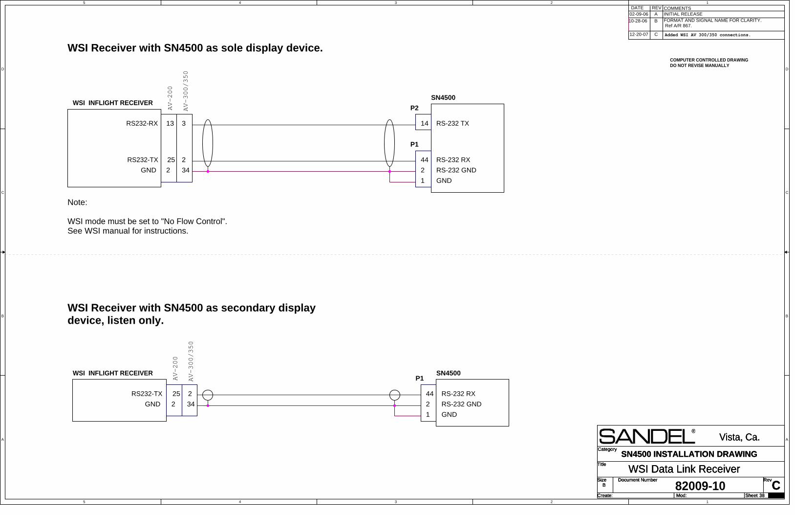
5
5
4
4
3
3
2
2
1
1
D D
C C
B B
A A
Title
Size Document Number Rev
Create: Sheet of
Category
Mod:
CWSI Data Link Receiver
Vista, Ca.
B
38
SN4500 INSTALLATION DRAWINGTitle
Size Document Number Rev
Create: Sheet of
Category
Mod:
CWSI Data Link Receiver
Vista, Ca.
B
38
SN4500 INSTALLATION DRAWINGTitle
Size Document Number Rev
Create: Sheet of
Category
Mod:
CWSI Data Link Receiver
Vista, Ca.
B
38
SN4500 INSTALLATION DRAWING
WSI Receiver with SN4500 as sole display device.
Note:
WSI mode must be set to "No Flow Control".See WSI manual for instructions.
RS232-RX
RS232-TX
13
25
WSI INFLIGHT RECEIVER
GND 2
P2
14 RS-232 TX
P1
44
2
1
RS-232 RX
RS-232 GND
GND
SN4500
GND
25
WSI Receiver with SN4500 as secondary displaydevice, listen only.
RS-232 GND
RS-232 RX
GND 22
1
WSI INFLIGHT RECEIVER
44
P1SN4500
RS232-TX
INITIAL RELEASEDATE REV COMMENTS
A
COMPUTER CONTROLLED DRAWINGDO NOT REVISE MANUALLY
82009-10
B FORMAT AND SIGNAL NAME FOR CLARITY. Ref A/R 867.
02-09-06
10-28-06
3
2
34AV-200
AV-300/350
2
34
AV-200
AV-300/350
12-20-07 C Added WSI AV 300/350 connections.
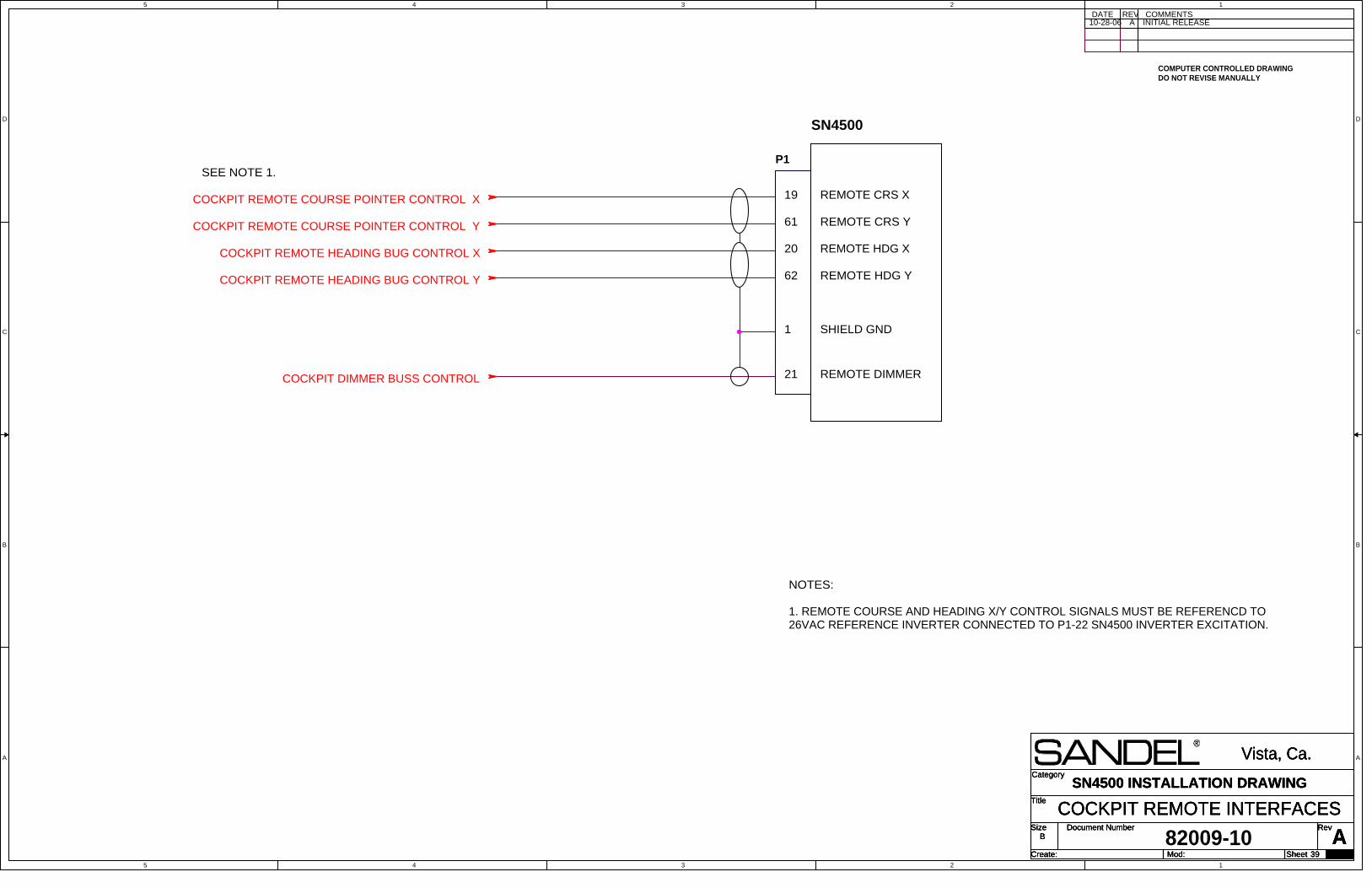
5
5
4
4
3
3
2
2
1
1
D D
C C
B B
A A
COCKPIT REMOTE COURSE POINTER CONTROL X
COCKPIT REMOTE COURSE POINTER CONTROL Y
COCKPIT REMOTE HEADING BUG CONTROL X
COCKPIT REMOTE HEADING BUG CONTROL Y
COCKPIT DIMMER BUSS CONTROL
Title
Size Document Number Rev
Create: Sheet of
Category
Mod:
ACOCKPIT REMOTE INTERFACES
Vista, Ca.
B
39
SN4500 INSTALLATION DRAWINGTitle
Size Document Number Rev
Create: Sheet of
Category
Mod:
ACOCKPIT REMOTE INTERFACES
Vista, Ca.
B
39
SN4500 INSTALLATION DRAWINGTitle
Size Document Number Rev
Create: Sheet of
Category
Mod:
ACOCKPIT REMOTE INTERFACES
Vista, Ca.
B
39
SN4500 INSTALLATION DRAWING
INITIAL RELEASEDATE REV COMMENTS
A
COMPUTER CONTROLLED DRAWINGDO NOT REVISE MANUALLY
82009-10
P1
19
61
20
REMOTE CRS X
SN4500
REMOTE CRS Y
REMOTE HDG X
REMOTE HDG Y62
REMOTE DIMMER21
SHIELD GND1
10-28-06
NOTES:
1. REMOTE COURSE AND HEADING X/Y CONTROL SIGNALS MUST BE REFERENCD TO26VAC REFERENCE INVERTER CONNECTED TO P1-22 SN4500 INVERTER EXCITATION.
SEE NOTE 1.

5
5
4
4
3
3
2
2
1
1
D D
C C
B B
A A
Title
Size Document Number Rev
Create: Sheet of
Category
Mod:Monday, December 10, 2007
BSN4500 with SG102 ARINC 429 or 407 Interface
Vista, Ca.
B
40 29
SN4500 INSTALLATION DRAWING
Friday, February 10, 2012
Title
Size Document Number Rev
Create: Sheet of
Category
Mod:Monday, December 10, 2007
BSN4500 with SG102 ARINC 429 or 407 Interface
Vista, Ca.
B
40 29
SN4500 INSTALLATION DRAWING
Friday, February 10, 2012
Title
Size Document Number Rev
Create: Sheet of
Category
Mod:Monday, December 10, 2007
BSN4500 with SG102 ARINC 429 or 407 Interface
Vista, Ca.
B
40 29
SN4500 INSTALLATION DRAWING
Friday, February 10, 2012
ARINC 429 HEADING INTERFACE
ARINC 407 SYNCHROHEADING INTERFACE P1
14
5
15
22
1
X OUT
Y OUT
26VAC INVERTER
P1
20
12
1
429 A OUT
3
SHIELD GND
429 B OUT
3
45
1
HDG1A ARINC 407
SHIELD GND
45
HDG1B ARINC 407
1
HDG1A ARINC 429
HDG1B ARINC 429
SN4500
P1
SN4500
GND
SG102
22INVERTER EXC.
P1
HDG1 VALID VALID GND25
GND
SG102NOTES UNLESS OTHERWISE SPECIFIED
1. Unless otherwise noted, all signal wiring is 22 to 24 AWG.
12-DEC-07 A INITIAL RELEASEDATE REV COMMENTS
COMPUTER CONTROLLED DRAWINGDO NOT REVISE MANUALLY
82009-10
B10-FEB-12 P1 PIN 20 WAS 30 A/R 1220
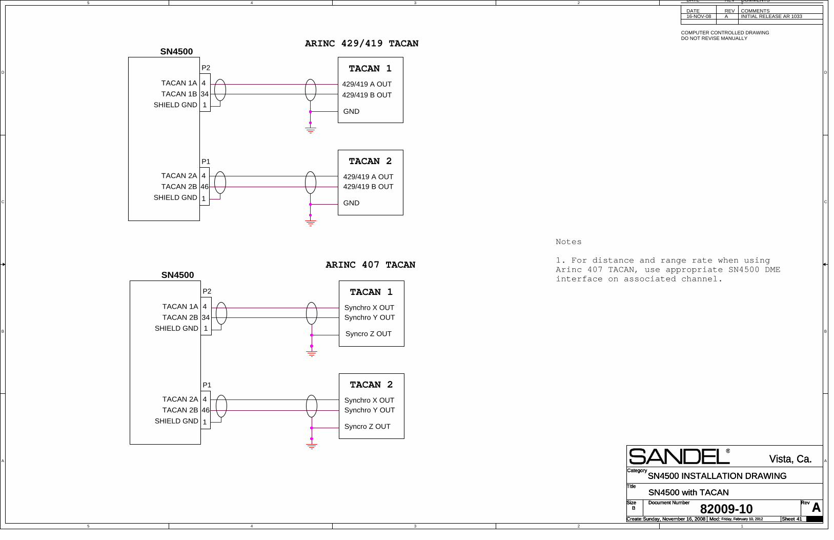
5
5
4
4
3
3
2
2
1
1
D D
C C
B B
A A
Title
Size Document Number Rev
Create: Sheet of
Category
Mod:Sunday, November 16, 2008
ASN4500 with TACAN
Vista, Ca.
B
41 29
SN4500 INSTALLATION DRAWING
Friday, February 10, 2012
Title
Size Document Number Rev
Create: Sheet of
Category
Mod:Sunday, November 16, 2008
ASN4500 with TACAN
Vista, Ca.
B
41 29
SN4500 INSTALLATION DRAWING
Friday, February 10, 2012
Title
Size Document Number Rev
Create: Sheet of
Category
Mod:Sunday, November 16, 2008
ASN4500 with TACAN
Vista, Ca.
B
41 29
SN4500 INSTALLATION DRAWING
Friday, February 10, 2012
429/419 A OUT429/419 B OUT
GND
4
46
1
P1
TACAN 2A
TACAN 2B
SHIELD GND
TACAN 1
TACAN 2
Synchro X OUTSynchro Y OUT
Syncro Z OUT
4
46
1
P1
TACAN 2A
TACAN 2B
SHIELD GND
TACAN 1
TACAN 2
ARINC 407 TACAN
SHIELD GND
TACAN 1A
TACAN 2B
SN4500
P2
4
34
1
Synchro X OUTSynchro Y OUT
Syncro Z OUT
82009-10
Notes
1. For distance and range rate when usingArinc 407 TACAN, use appropriate SN4500 DMEinterface on associated channel.
DATE REV COMMENTS
ARINC 429/419 TACAN
429/419 A OUT
429/419 B OUTSHIELD GND
TACAN 1A
TACAN 1B
SN4500
GND
P2
4
34
1
16-NOV-08 A INITIAL RELEASE AR 1033DATE REV COMMENTS
COMPUTER CONTROLLED DRAWINGDO NOT REVISE MANUALLY

5
5
4
4
3
3
2
2
1
1
D D
C C
B B
A A
Title
Size Document Number Rev
Create: Sheet of
Category
Mod:Friday, September 12, 2008
ANVIS CONTROL
Vista, Ca.
B
42 29
SN4500 INSTALLATION DRAWING
Friday, February 10, 2012
Title
Size Document Number Rev
Create: Sheet of
Category
Mod:Friday, September 12, 2008
ANVIS CONTROL
Vista, Ca.
B
42 29
SN4500 INSTALLATION DRAWING
Friday, February 10, 2012
Title
Size Document Number Rev
Create: Sheet of
Category
Mod:Friday, September 12, 2008
ANVIS CONTROL
Vista, Ca.
B
42 29
SN4500 INSTALLATION DRAWING
Friday, February 10, 2012
See note 2.
(USING REMOTE GROUND)
(USING INSTRUMENT GROUND)
See note 3
82009-10
1. Use 24 AWG stranded shielded 1 or 2conductor wire as required.
2. TYCO P/N TT13A9T1/404 toggle switch orequivalent. A push-on/push-off pushbutton switchmay be used. Annunciator not required.
3. Use closest available airframe ground.
4. In the event of a broken wire fault the SN4500will default to daylight (non NVIS) mode.
12-SEP-08 A INITIAL RELEASE AR 1033DATE REV COMMENTS
COMPUTER CONTROLLED DRAWINGDO NOT REVISE MANUALLY
AIRCRAFT GND
NVIS CONTROL
SN4500
P3
Notes:
See note 2.
AIRCRAFT GND
NVIS CONTROL
SN4500
P3
13
11
13
11
NVIS Control SwitchNVIS Control Switch
NVIS Control SwitchNVIS Control Switch

5
5
4
4
3
3
2
2
1
1
D D
C C
B B
A A
Title
Size Document Number Rev
Create: Sheet of
Category
Mod:
BREVERSIONARY ATTITUDE DISPLAY OPTION
Vista, Ca.
B
43 29
SN4500 INSTALLATION DRAWING
Friday, February 10, 2012
Title
Size Document Number Rev
Create: Sheet of
Category
Mod:
BREVERSIONARY ATTITUDE DISPLAY OPTION
Vista, Ca.
B
43 29
SN4500 INSTALLATION DRAWING
Friday, February 10, 2012
Title
Size Document Number Rev
Create: Sheet of
Category
Mod:
BREVERSIONARY ATTITUDE DISPLAY OPTION
Vista, Ca.
B
43 29
SN4500 INSTALLATION DRAWING
Friday, February 10, 2012
See note 2.
(USING REMOTE GROUND)
(USING INSTRUMENT GROUND)
See note 6.
1. Use 24 AWG stranded shielded 1 or 2conductor wire as required.
2. TYCO P/N TT13A9T1/404 toggle switch orequivalent. A push-on/push-off pushbuttonswitch may be used. Annunciator not required.
3. Placard the switch "REV".
4. Locate switch and placard nearest positionavailable to SN4500.
5. Assure adequate illuminatin of switch andplacard for night operations under normalconditions.
6. Use closest available airframe ground.
7. In the event of a broken wire fault theSN4500 will default to normal display(non-reversionary) mode.
8. Standard configuration is to use P3-6 forREV CNTRL. If P3-6 is needed for AnalogDME Valid (see section 2.5.3 page 2-12), useP3-13. NVIS/REV ATT/DME Analog Valid maynot all be used simultaneously.
82009-10
A12-JAN-09
DATE
INITIAL RELEASE AR1048
COMPUTER CONTROLLED DRAWINGDO NOT REVISE MANUALLY
COMMENTSREV
REV CNTRL
AIRCRAFT GND
SN4500
P3
11
6/13
Notes:
See note 2.
P1
20
12
1
429 A OUT
429 B OUT
3
SHIELD GND
45
1
HDG1A ARINC 429
HDG1B ARINC 429
P1
GND
SG102 AHRSor equivalent device(SG102 shown)
REV CNTRL
AIRCRAFT GND
SN4500
P3
11
P1
20
12
1
429 A OUT
429 B OUT
3
SHIELD GND
45
1
HDG1A ARINC 429
HDG1B ARINC 429
P1
GND
SG102 AHRSor equivalent device(SG102 shown)
11-FEB-08 A1 CORRECTED INITIAL RELEASE DATEAND PIN OUT AR1048
10-FEB-12 B P3 PINS 6/13 WAS 6 UPDATED NOTE 8A/R 1220
6/13
Reversionary Control SwitchReversionary Control Switch
Reversionary Control SwitchReversionary Control Switch
Related Documents
![82011-IM, REV J. SG102/MT102 Installation Manual...82011-IM, REV J Sandel SG102 & MT102 Installation Manual Page ii [This page intentionally left blank] 82011-IM, REV J Sandel SG102](https://static.cupdf.com/doc/110x72/6123df842435380c1c6b0381/82011-im-rev-j-sg102mt102-installation-manual-82011-im-rev-j-sandel-sg102.jpg)