SMC-Flex™ Getting Started Introduction This guide provides you with the basic information required to start up your SMC-Flex™ controller. Factory default settings and information regarding installing, and programming, the controller are described here. This guide is intended for qualified service personnel responsible for setting up and servicing these devices. You must have previous experience with and a basic understanding of electrical terminology, configuration procedures, required equipment, and safety precautions. Installation The open-style design of the SMC-Flex controller requires that it be installed in an enclosure. The internal temperature of the enclosure must be kept within -5…50°C (23…122°F). The controller is fan cooled. It is important to mount the controller in a position that allows air to flow vertically through the power structure. Allow for a minimum of six inches (15 cm) of free space around all sides of the controller.

Welcome message from author
This document is posted to help you gain knowledge. Please leave a comment to let me know what you think about it! Share it to your friends and learn new things together.
Transcript

SMC-Flex™Getting Started
Introduction This guide provides you with the basic information required to start up your SMC-Flex™ controller. Factory default settings and information regarding installing, and programming, the controller are described here.
This guide is intended for qualified service personnel responsible for setting up and servicing these devices. You must have previous experience with and a basic understanding of electrical terminology, configuration procedures, required equipment, and safety precautions.
Installation The open-style design of the SMC-Flex controller requires that it be installed in an enclosure. The internal temperature of the enclosure must be kept within -5…50°C (23…122°F).
The controller is fan cooled. It is important to mount the controller in a position that allows air to flow vertically through the power structure. Allow for a minimum of six inches (15 cm) of free space around all sides of the controller.

Publication 150-QS001D-EN-P - June 2005
2 SMC-Flex™ Getting Started
Wiring Power Wiring
Refer to the product nameplate for power lug termination information including:
• Lug wire capacity
• Tightening torque requirements
• Lug kit catalog numbers (108…480 A)
Control Wiring
Refer to the product nameplate for control terminal wire capacity and tightening torque requirements. Each control terminal will accept a maximum of two wires.
The SMC-Flex controller accepts control power input of 100…240V AC or 24V AC/DC, (+10/–15%) single-phase, 50/60 Hz. Refer to the product nameplate prior to applying control power. Connect control power to the controller at terminals 11 and 12. For controllers rated 1…480 A (1.7…831 Delta), control power of 125 VA is also required. The control power requirement for the control module is 75 VA. The control power requirement for the fans is 20 or 50 VA. Depending on the specific application, additional control circuit transformer VA capacity may be required.
Control Terminals
Figure 1: SMC-Flex Controller Control Terminals

Publication 150-QS001D-EN-P - May 2005
SMC-Flex™ Getting Started 3
Table 1 Control Terminal Designation
Terminal Number Description
11 Control Power Input ➌
12 Control Power Common ➌
13 Controller Enable Input ➊
14 Ground
15 Option Input #2 ➊➌
16 Option Input #1 ➊➌
17 Start Input ➊➌
18 Stop Input ➊➌
19 Aux. Contact #1 ➋➌
20 Aux. Contact #1 ➋➌
21 Not Used
22 Not Used
23 PTC Input ➊
24 PTC Input ➊
25 TACH Input
26 TACH Input
27 Ground Fault Transformer Input ➊
28 Ground Fault Transformer Input ➊
29 Aux. Contact #2 ➋➌
30 Aux. Contact #2 ➋➌
31 Aux. Contact #3 ➋➌
32 Aux. Contact #3 ➋➌
33 Aux. Contact #4 ➋➌
34 Aux. Contact #4 ➋➌
➊ Do not connect any additional loads to these terminals. These “parasitic” loads may cause problems with operation, which may result in false starting and stopping.
➋ External Bypass operates an external contactor and overload once the meter reaches full speed. The SMC-Flex overload functionality is disabled when the external bypass is activated. Proper sizing of the contactor and overload is required.
➌ RC Snubbers are required on loads connected to auxiliary.
Publication 150-QS001D-EN-P - June 2005
4 SMC-Flex™ Getting Started
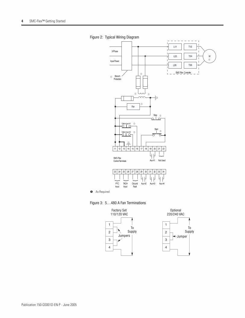
Figure 2: Typical Wiring Diagram
Figure 3: 5…480 A Fan Terminations
23 24 25 26 27 28 29 30 31 32 33 34
11 12 13 14 15 16 17 18 19 20 21 22
Option Input #1
Option Input #2
Stop
Start
SMC-FlexControl Terminals
}}}
3-Phase
Input Power
BranchProtection
SMC-Flex Controller
PTCInput
TACHInput
GroundFault
Aux #2 Aux #3 Aux #4
M
➀
➀
➀
➀➀
➀ ➀
➀
➀
➀
L1/1 T1/2
T2/4
T3/6
L2/3
L3/5
Fan
}
Not Used Aux #1
➊ As Required
Factory Set 110/120 VAC
Optional 220/240 VAC
Jumpers
To Supply
Jumper
To Supply
1
2
3
4
1
2
3
4

Publication 150-QS001D-EN-P - May 2005
SMC-Flex™ Getting Started 5
Programming The SMC-Flex controller can be programmed with the built-in keypad and LCD display or with the optional Bulletin 20-HIM-xx LCD human interface modules. Parameters are organized in a three-level menu structure and divided into programming groups.
Keypad Description
The functions of each programming key are described below.
Table 2 Keypad Descriptions
Escape Exit a menu, cancel a change to a parameter value, or acknowledge a fault/alarm.
Select Select a digit, select a bit, or enter edit mode in a parameter screen.Will get to menu to change the language being displayed.
Up/Down Arrows
Scroll through options increase/decrease a value, or toggle a bit.
Enter Enter a menu, enter edit mode in a parameter screen, or save a change to a parameter value.
Esc
Sel
Lang

Publication 150-QS001D-EN-P - June 2005
6 SMC-Flex™ Getting Started
Figure 4: Menu Structure Hierarchy
➊ The SMC-Flex controller does not support EEPROM, Link, Process, or Start-up modes.➋ Steps back one level
Device
Power-up andStatus Display
ParameterMemoryStorage Preferences DiagnosticsSelect
0
MonitoringSet UpMotor ProtectionCommunicationsUtilityLinear LIst
0
SMC-FLEX0
Reset to Defaults0
Change PasswordUser Dspl LineUser Dspl TimeUser Dspl VideoReset User Display
0
AlarmsFaultsDevice Revision
Choose ModeOPERATION LEVEL
MAIN MENU➊
➁
➋
Parameter menucontinued in Figure 5
GROUP MENU
or oror orEsc Sel
or
Esc
Esc
0
Select languagebeing displayed
Lang

Publication 150-QS001D-EN-P - May 2005
SMC-Flex™ Getting Started 7
Figure 5: Parameter Menu Structure
➊ Depending upon SMC option selected, some parameters may not appear in product display.➋ Steps back one level➌ For further information on parameters, see Appendix B of the SMC-Flex User Manual, Publication
150-UM008*-EN-P.➍ For further information on parameter management, see page 10.
Parameter
0
Metering Basic (Brake) Overload Jam Comm Masks Language Linear List
Volts Phase A-B SMC Option Overload Class Jam F Lvl Logic Mask Language All parametersVolts Phase B-C Motor Connection Service Factor Jam F Dly Parameter Mgt ➃ Parameter Mgt ➃ Parameter Mgt ➃Volts Phase C-A Line Voltage Motor FLC Jam A LvlCurrent Phase A Starting Mode Overload Reset Jam A Dly
DataLinks Motor DataCurrent Phase B Ramp Time Overload A Lvl Parameter Mgt ➃Current Phase C Initial Torque Parameter Mgt ➃ Data In A1 MotorFLCWatt Meter Cur Limit Lvl
StallData In A2 Motor ID
Kilowatt Hours Kickstart Time Underload Data In B1 Parameter Mgt ➃Elapsed Time Kickstart Lvl Stall Dly Data In B2Meter Reset Stop Input Underload F Lvl Parameter Mgt ➃ Data In C1Power Factor Option 1 Input Underload F Dly Data In C2Mtr Therm Usage Option 2 Input Underload A Lvl Ground Fault Data In D1Motor Speed Stop Mode Underload A Dly Data In D2
Stop Time Parameter Mgt ➃ Gnd Flt Enable Data Out A1Braking Current Gnd Flt Lvl Data Out A2Overload Class Undervoltage Gnd Flt Dly Data Out B1Service Factor Gnd Flt Inh Time Data Out B2Motor FLC Undervolt F Lvl Gnd Flt A Enable Data Out C1Overload Reset Undervolt F Dly Gnd Flt A Lvl Data Out C2Aux1 Config Undervolt A Lvl Gnd Flt A Dly Data Out D1Aux2 Config Undervolt A Dly Parameter Mgt ➃ Data Out D2Aux3 Config Parameter Mgt ➃ Parameter Mgt ➃Aux4 Config PTCBackspin Timer
OvervoltageParameter Mgt ➃ PTC EnableOvervolt F Lvl Parameter Mgt ➃
Dual Ramp (Option 2 Input == Dual Ramp)
Overvolt F DlyOvervolt A Lvl Phase ReversalOvervolt A Dly
Starting Mode 2 Parameter Mgt ➃ Phase ReversalRamp Time 2 Parameter Mtg ➃Initial Torque 2 UnbalanceCur Limit Lvl 2 RestartKickstart Time 2 Unbalance F LvlKickstart Lvl 2 Unbalance F Dly Starts Per HourParameter Mgt ➃ Unbalance A Lvl Restart Attempts
Unbalance A Dly Restart DlyPreset SS (Option 2 Input = Preset SS)
Parameter Mgt ➃ Parameter Mtg ➃
Slow Speed SelSlow Speed DirSlow Accel CurSlow Running CurParameter Mgt ➃
(Option 2 Input = Accu-Stop)Slow Speed SelSlow Accel CurSlow Running CurBraking CurrentStopping CurrentParameter Mgt ➃
MotorSet Up Utility Linear ListProtection
Parameter
Monitoring Communications
➀➂➁
Esc
Publication 150-QS001D-EN-P - June 2005
8 SMC-Flex™ Getting Started
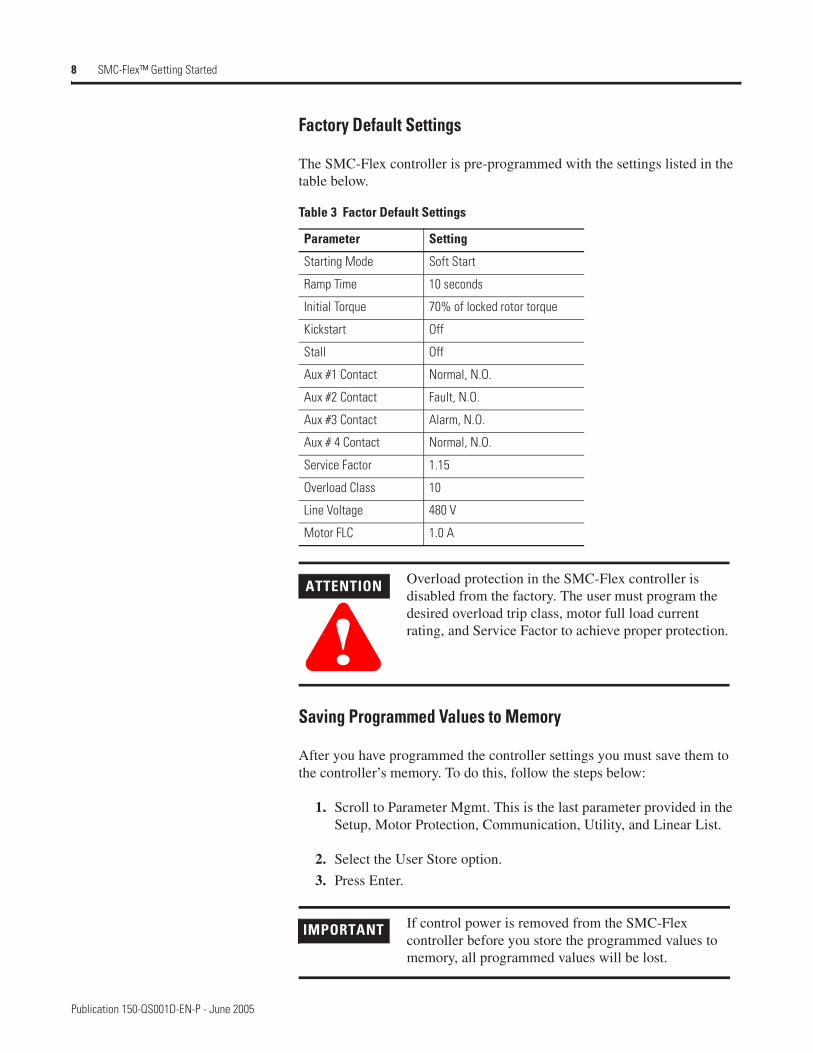
Factory Default Settings
The SMC-Flex controller is pre-programmed with the settings listed in the table below.
Saving Programmed Values to Memory
After you have programmed the controller settings you must save them to the controller’s memory. To do this, follow the steps below:
1. Scroll to Parameter Mgmt. This is the last parameter provided in the Setup, Motor Protection, Communication, Utility, and Linear List.
2. Select the User Store option.
3. Press Enter.
Table 3 Factor Default Settings
Parameter Setting
Starting Mode Soft Start
Ramp Time 10 seconds
Initial Torque 70% of locked rotor torque
Kickstart Off
Stall Off
Aux #1 Contact Normal, N.O.
Aux #2 Contact Fault, N.O.
Aux #3 Contact Alarm, N.O.
Aux # 4 Contact Normal, N.O.
Service Factor 1.15
Overload Class 10
Line Voltage 480 V
Motor FLC 1.0 A
ATTENTION
!Overload protection in the SMC-Flex controller is disabled from the factory. The user must program the desired overload trip class, motor full load current rating, and Service Factor to achieve proper protection.
IMPORTANT If control power is removed from the SMC-Flex controller before you store the programmed values to memory, all programmed values will be lost.

Publication 150-QS001D-EN-P - May 2005
SMC-Flex™ Getting Started 9
Basic Setup To properly setup the SMC-Flex, go to the Basic Setup list and set parameters to meet the application needs. Motor FLA and Service Factor must also be setup for proper operation. No additional calibration procedures are necessary for proper operation of the SMC-Flex.
Communication A serial interface port for DPI (Drives Peripheral Interface) communication modules is provided as standard. DeviceNet, ControlNet, EtherNet, RS-485, RIO, ProfiBUS, and InterBUS communication modules are also available (Bulletin 20-COMM).
A serial interface port called DPI is provided as standard, and allows connection to a Bulletin 20-HIM-C3 human interface module.
Figure 6: SMC-Flex DPI Location
ATTENTION
!Two peripheral HIM devices can be connected to the SMC-Flex. The maximum output current through the SMC-Flex is 280 mA.
The SMC-Flex allows HIM interface and DPI communication.
Publication 150-QS001D-EN-P - June 2005
10 SMC-Flex™ Getting Started
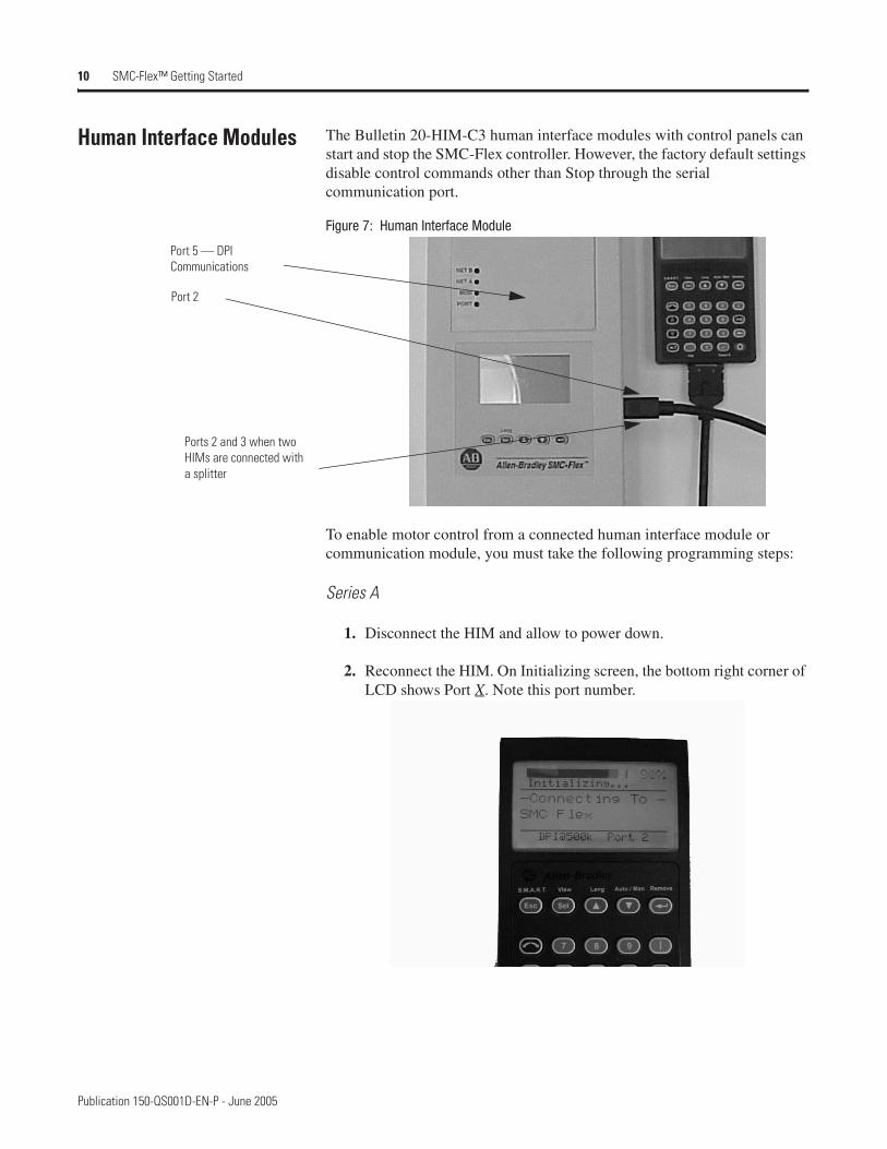
Human Interface Modules The Bulletin 20-HIM-C3 human interface modules with control panels can start and stop the SMC-Flex controller. However, the factory default settings disable control commands other than Stop through the serial communication port.
Figure 7: Human Interface Module
To enable motor control from a connected human interface module or communication module, you must take the following programming steps:
Series A
1. Disconnect the HIM and allow to power down.
2. Reconnect the HIM. On Initializing screen, the bottom right corner of LCD shows Port X. Note this port number.
Port 5 — DPI Communications
Port 2
Ports 2 and 3 when two HIMs are connected with a splitter

Publication 150-QS001D-EN-P - May 2005
SMC-Flex™ Getting Started 11
3. Go to Logic Mask, found as follows: Main Menu: Parameter/Communications/Comm Mask/Logic Mask
4. Set b0X equal to 1 (where X is the port number noted in step 2).
5. Go to Parameter Management and save as User Store.
IMPORTANT The Logic Mask must be set to 0 prior to disconnecting a human interface module from the SMC-Flex controller. If not, the unit will fault on a “Coms Loss”.

Publication 150-QS001D-EN-P — May 2005 40055-217-01 (4)Supersedes Publication 150-QS001C-EN-P — June 2004 © 2005 Rockwell International Corporation. Printed in the U.S.A.
Related Documents