TOUCHPAD USER GUIDE Smartzone LCD www.ias.net.au

Welcome message from author
This document is posted to help you gain knowledge. Please leave a comment to let me know what you think about it! Share it to your friends and learn new things together.
Transcript

TOUCHPAD USER GUIDE
Smartzone LCD
www.ias.net.au

RC-SZ-PLUS-LCD-IC-EA
SMARTZONE LCDTOUCHPAD USER GUIDE
PAGE 2
Touchpad and Display Layout
RC-SZ-PLUS-LCD-IC-EA
SMARTZONE LCDTOUCHPAD USER GUIDE
PAGE 3
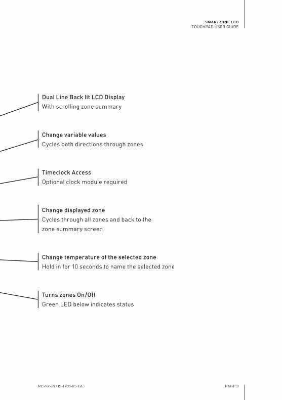
Dual Line Back lit LCD Display
With scrolling zone summary
Change variable values
Cycles both directions through zones
Timeclock Access
Optional clock module required
Change displayed zone
Cycles through all zones and back to the
zone summary screen
Change temperature of the selected zone
Hold in for 10 seconds to name the selected zone
Turns zones On/Off
Green LED below indicates status

RC-SZ-PLUS-LCD-IC-EA
SMARTZONE LCDTOUCHPAD USER GUIDE
PAGE 4
Overview
The Smartzone Zoning System, when installed with the optional Smartzone
Bridge module and a compatible IAS unit controller (thermostat),
communicates with the thermostat to automatically control the thermostat’s
mode selection and setpoint adjustment.
Without these modules it is necessary to set the operating mode (heating or
cooling) and the setpoint from the thermostat that was supplied with the A/C
unit as follows (refer to the instructions for the thermostat for details).
If the majority of zones require cooling, set the operating mode of the
thermostat to cooling and make the setpoint of the thermostat 0.5°C less
than the lowest zone setpoint.
If the majority of zones require heating, set the operating mode of the
thermostat to heating and make the setpoint of the thermostat 0.5°C more
than the highest zone setpoint.
This additional 0.5°C ensures that the unit continues to run until all zones
reach setpoint.

RC-SZ-PLUS-LCD-IC-EA
SMARTZONE LCDTOUCHPAD USER GUIDE
PAGE 5
Selecting a Zone
Press or and to cycle from the zone summary screen,
through each of the individual zone status screens.
The zone summary screen is depicted in the image on page 2.
Activating / Deactivating Zones
Press or and to select the zone to be activated /
deactivated. The current status of the selected zone is displayed on the
second line of the LCD read-out.
Press to turn the zone ON or OFF as required. The green LED
below the button indicates the zones on/off status.
Alternatively, all zones can be activated / deactivated simultaneously by the
selecting the zone summary screen then pressing .
Setting a Zone Temperature
Press or and to select the target zone.
Press .
Use or to adjust the set point to the desired level.
Press to save and exit.
1.
1.
2.
1.
2.
3.
4.

RC-SZ-PLUS-LCD-IC-EA
SMARTZONE LCDTOUCHPAD USER GUIDE
PAGE 6
Naming Zones
Zone names must be eight characters in length. A blank character must be
used to fi ll spaces where no letters are required.
Press or and to select the zone to be named.
Press and hold for approximately ten seconds, until the display
reads Z1 Name: .
Use and to view all of the preset zone names.
Press on your choice (e.g. Lounge, Games or Custom). See
tip below.
Use or to change the fi rst character of the zone name if
required. Press and hold or to scroll quickly through the
available characters.
Press to move to the next character. Press to return to the
previous character to correct a mistake.
Repeat steps 5 & 6 for all eight character spaces.
Pressing to accept the fi nal character will save the zone name and
the controller will return to the standard display.
Tip: To accept one of the preset zone names, press repeatedly to
accept each character including any blanks until the controller reverts to the
standard display.
1.
2.
3.
4.
5.
6.
7.
8.
RC-SZ-PLUS-LCD-IC-EA
SMARTZONE LCDTOUCHPAD USER GUIDE
PAGE 7
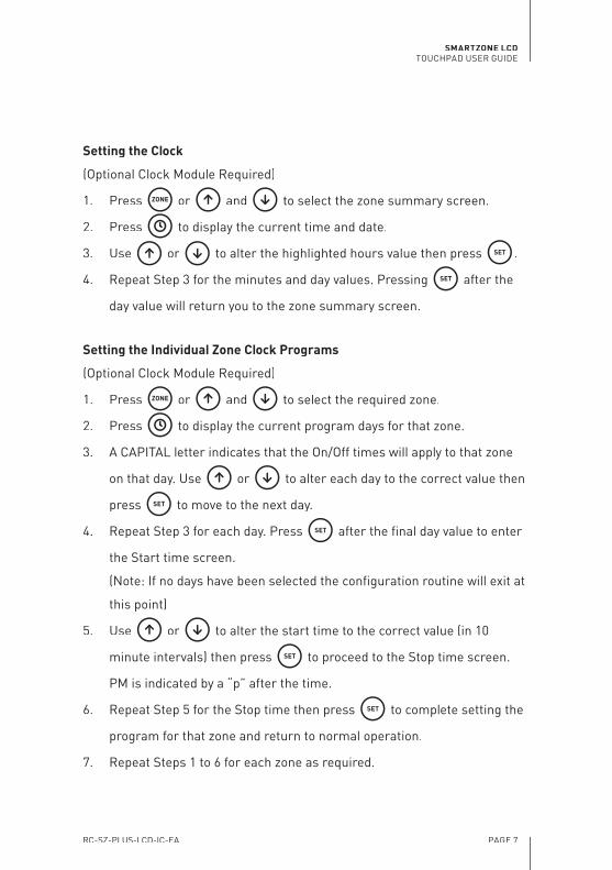
Setting the Clock
(Optional Clock Module Required)
Press or and to select the zone summary screen.
Press to display the current time and date.
Use or to alter the highlighted hours value then press .
Repeat Step 3 for the minutes and day values. Pressing after the
day value will return you to the zone summary screen.
Setting the Individual Zone Clock Programs
(Optional Clock Module Required)
Press or and to select the required zone.
Press to display the current program days for that zone.
A CAPITAL letter indicates that the On/Off times will apply to that zone
on that day. Use or to alter each day to the correct value then
press to move to the next day.
Repeat Step 3 for each day. Press after the fi nal day value to enter
the Start time screen.
(Note: If no days have been selected the confi guration routine will exit at
this point)
Use or to alter the start time to the correct value (in 10
minute intervals) then press to proceed to the Stop time screen.
PM is indicated by a “p” after the time.
Repeat Step 5 for the Stop time then press to complete setting the
program for that zone and return to normal operation.
Repeat Steps 1 to 6 for each zone as required.
1.
2.
3.
4.
1.
2.
3.
4.
5.
6.
7.

RC-SZ-PLUS-LCD-IC-EA
SMARTZONE LCDTOUCHPAD COMMISSIONING
PAGE 8
Commissioning Instructions - For Initial Setup
CAUTION: Making adjustments to systems setting may adversley affect
system operation.
INSTALLER TIP: Make up a short cable and perform steps 1 to 8 with the
touchpad in the ceiling space next to the main modules
1. Before applying power to the system.
Ensure that all core modules are fi rmly connected together via the DB9
connector and that the modules are fi xed in place so they cannot come apart.
THESE MODULES MAY BE DAMAGED IF THEY ARE SEPARATED WHILE
POWER IS APPLIED TO THE SYSTEM.
Ensure that all touchpads, sensors and motors are connected as per the
connection diagram supplied.
DO NOT CONNECT SENSORS TO MOTOR OUTPUTS. SENSORS MAY BE
DAMAGED IF POWER IS APPLIED IN THIS CASE.
Ensure the air conditioning system is OFF.
2. Spill Zone Confi guration
If there is no dedicated bypass damper installed, a spill zone(s) may be
designated by turning on one or more of the spill DIP switches on the
Main Processor Module.
3. Initial Power Check
When power is applied to the system, the startup routine will drive all zone
damper motors to the fully open position, the dedicated bypass damper (if
installed) will drive to the fully closed position, then all dampers will drive to
•
•
•
•
RC-SZ-PLUS-LCD-IC-EA
SMARTZONE LCDTOUCHPAD COMMISSIONING
PAGE 9
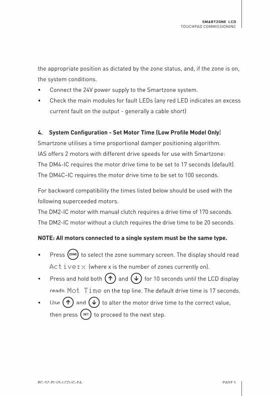
the appropriate position as dictated by the zone status, and, if the zone is on,
the system conditions.
Connect the 24V power supply to the Smartzone system.
Check the main modules for fault LEDs (any red LED indicates an excess
current fault on the output - generally a cable short)
4. System Confi guration - Set Motor Time (Low Profi le Model Only)
Smartzone utilises a time proportional damper positioning algorithm.
IAS offers 2 motors with different drive speeds for use with Smartzone:
The DM4-IC requires the motor drive time to be set to 17 seconds (default).
The DM4C-IC requires the motor drive time to be set to 100 seconds.
For backward compatibility the times listed below should be used with the
following superceeded motors.
The DM2-IC motor with manual clutch requires a drive time of 170 seconds.
The DM2-IC motor without a clutch requires the drive time to be 20 seconds.
NOTE: All motors connected to a single system must be the same type.
Press to select the zone summary screen. The display should read
Active:x (where x is the number of zones currently on).
Press and hold both and for 10 seconds until the LCD display
reads Mot Time on the top line. The default drive time is 17 seconds.
Use and to alter the motor drive time to the correct value,
then press to proceed to the next step.
•
•
•
•
•

RC-SZ-PLUS-LCD-IC-EA
SMARTZONE LCDTOUCHPAD COMMISSIONING
PAGE 10
5. System Confi guration - Set Spill Air Setpoint
The Spill Air Setpoint value can be determined by one of the methods
described in Appendix A on page 15.
The display should now read SpillSet on the top line.
Use and to alter the spill air setpoint, then press to
proceed to the next step.
6. System Confi guration - Set Minimum Ventilation Parameters
The Smartzone can be programmed to allow a minimum airfl ow to all zones
that are ON. This is adjustable from 0 to 30 % open and defaults to zero. This
value effects all ON zones equally.
The zone motors will close fully when the zone is turn turned OFF.
The display should now read Min Vent on the top line.
Use and to alter the minimum ventilation setting and press
to proceed to the next stage.
7. System Confi guration - Set Supply Air Safety Setpoints
The supply air safety minimum & maximum set points reduce the risk of
damage to the system due to over cooling or heating. When these points are
reached, all dampers open to maximise airfl ow across the coil.
Refer to the unit manufacturers documentation to ascertain the minimum
and maximum air off coil temperature.
The display should now read LoSA=xx (where xx is the current
supply air safety minimum temperature. Default = 8°C. Below this is the
current supply air temperature in brackets).
•
•
•
•
•
RC-SZ-PLUS-LCD-IC-EA
SMARTZONE LCDTOUCHPAD COMMISSIONING
PAGE 11
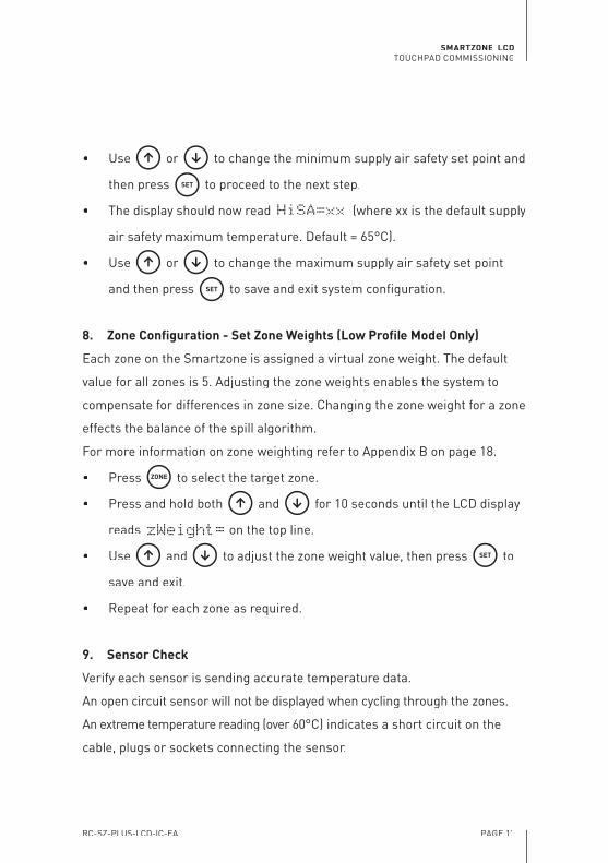
Use or to change the minimum supply air safety set point and
then press to proceed to the next step.
The display should now read HiSA=xx (where xx is the default supply
air safety maximum temperature. Default = 65°C).
Use or to change the maximum supply air safety set point
and then press to save and exit system confi guration.
8. Zone Confi guration - Set Zone Weights (Low Profi le Model Only)
Each zone on the Smartzone is assigned a virtual zone weight. The default
value for all zones is 5. Adjusting the zone weights enables the system to
compensate for differences in zone size. Changing the zone weight for a zone
effects the balance of the spill algorithm.
For more information on zone weighting refer to Appendix B on page 18.
Press to select the target zone.
Press and hold both and for 10 seconds until the LCD display
reads zWeight= on the top line.
Use and to adjust the zone weight value, then press to
save and exit.
Repeat for each zone as required.
9. Sensor Check
Verify each sensor is sending accurate temperature data.
An open circuit sensor will not be displayed when cycling through the zones.
An extreme temperature reading (over 60°C) indicates a short circuit on the
cable, plugs or sockets connecting the sensor.
•
•
•
•
•
•
•
RC-SZ-PLUS-LCD-IC-EA
SMARTZONE LCDTOUCHPAD COMMISSIONING
PAGE 12
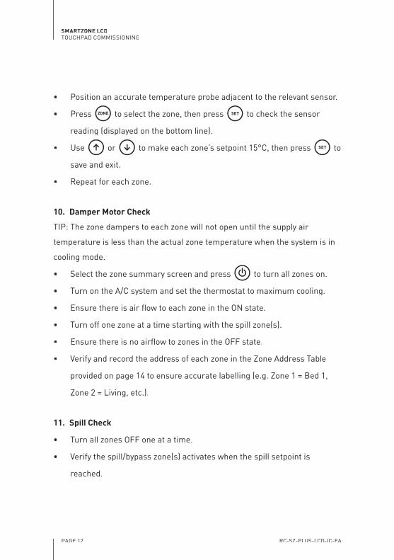
Position an accurate temperature probe adjacent to the relevant sensor.
Press to select the zone, then press to check the sensor
reading (displayed on the bottom line).
Use or to make each zone’s setpoint 15°C, then press to
save and exit.
Repeat for each zone.
10. Damper Motor Check
TIP: The zone dampers to each zone will not open until the supply air
temperature is less than the actual zone temperature when the system is in
cooling mode.
Select the zone summary screen and press to turn all zones on.
Turn on the A/C system and set the thermostat to maximum cooling.
Ensure there is air fl ow to each zone in the ON state.
Turn off one zone at a time starting with the spill zone(s).
Ensure there is no airfl ow to zones in the OFF state.
Verify and record the address of each zone in the Zone Address Table
provided on page 14 to ensure accurate labelling (e.g. Zone 1 = Bed 1,
Zone 2 = Living, etc.).
11. Spill Check
Turn all zones OFF one at a time.
Verify the spill/bypass zone(s) activates when the spill setpoint is
reached.
•
•
•
•
•
•
•
•
•
•
•
•

RC-SZ-PLUS-LCD-IC-EA
SMARTZONE LCDTOUCHPAD COMMISSIONING
PAGE 13
12. Name the zones
Refer to page 6 for instructions regarding naming zones.
13. Touchpad Confi guration
If more than one LCD touchpad has been installed, each touchpad can be
confi gured to restrict access to a subset of the total number of zones.
Set the touchpad DIP switches on the back of the touchpad to allow
access to the required zones as per Table 1.
LCD Touchpad Zone Selection Confi guration
SWITCH 1 SWITCH 2 SWITCH 3 SWITCH 4 TOUCHPAD WILL ACCESS ZONE(S)
OFF OFF OFF OFF All Zones (default)
ON OFF OFF OFF 1 only
OFF ON OFF OFF 2 only
ON ON OFF OFF 3 only
OFF OFF ON OFF 4 only
ON OFF ON OFF 5 only
OFF ON ON OFF 6 only
ON ON ON OFF 7 only
OFF OFF OFF ON 8 only
ON OFF OFF ON 1 & 2 only
OFF ON OFF ON 3 & 4 only
ON ON OFF ON 5 & 6 only
OFF OFF ON ON 7 & 8 only
ON OFF ON ON 1, 2, 3 & 4 only
OFF ON ON ON 5, 6, 7 & 8 only
ON ON ON ON 1, 2 & 3 only
Table 1.
•

RC-SZ-PLUS-LCD-IC-EA
SMARTZONE LCDTOUCHPAD COMMISSIONING
PAGE 14
14. Final Check
Verify all zones are approaching set point.
Complete the table below to ensure an accurate record of the physical zone
layout is available.
ZONE ADDRESS TABLE
Zone Number Zone Name (e.g. Living, Bed 1 etc.) Zone Weight
1
2
3
4
5
6
7
8
Spill Zone(s) =

RC-SZ-PLUS-LCD-IC-EA
SMARTZONE LCDAppendix A
PAGE 15
Appendix A - Spill/Bypass Setpoint
Overview
The Smartzone’s ingenious bypass system is the key to how it cycles the
main plant without the need for complex wiring. The Smartzone constantly
monitors the position of the dampers via the time proportional damper
positioning (TPDP) system. When the predetermined spill set point is
reached, the Smartzone begins to open the spill/bypass damper and
stimulates the main plant controllers return air sensor with conditioned air
(supply air).
If the main plant controller is operating in heating mode the introduction of
warm supply air stimulates the thermostat’s return air sensor, causing the
A/C unit to cycle off as the Smartzone is cycling the zones off.
If the main plant controller is operating in cooling mode the introduction of
cool supply air to the return air system achieves the same result.
The spill/bypass damper can be connected in one of two ways.
Option 1 - Bypass Damper
A duct is installed connecting the supply air duct to the return air duct via
the bypass damper. The Smartzone’s main processor module provides an
output dedicated to this function. This then leaves all other motor outputs
free to control up to eight zones. The plant controllers return air sensor
must be placed in a position between the bypass inlet to the return air duct
and the A/C plant.
NOTE: If the main plant controller cycles the indoor fan off between calls
for heating, any sensor positioned in the return air duct will be isolated
from the room condition when the air fl ow is halted. OPTION 2 MUST BE
USED IN THIS SITUATION.

RC-SZ-PLUS-LCD-IC-EA
SMARTZONE LCDAppendix A
PAGE 16
Option 2 - Spill Zone
One or more spill dampers can be used to control the temperature of zones
immediately adjacent the return air grille. Under normal operation the spill
damper(s) will operate as normal zones, but when the spill set point is
reached the spill zone(s) open to relieve duct pressure and cycle the main
plant off.
NOTE: When Option 2 is used, the spill zone(s) immediately adjacent the
return air grille may experience temperature variations, of between 0.5
°C and 1 °C, either side of set point. Therefore it is necessary to set the
temperature of the spill zone higher than the main plant controller set point
in cooling mode and lower than the main plant controller set point in heating
mode.
Methods for Calculating Spill/Bypass Setpoint
The spill air set point can be determined by utilising one or all of the following
methods:
a. Air Quantity
b. Supply Air Temperature
c. Diffuser Noise
The factory default spill setpoint is 33% of total zones open. Refer to page 8
for details on how to adjust the spill setpoint.
The following proceedures should be carried out when the system is set for
maximum conditioning.
RC-SZ-PLUS-LCD-IC-EA
SMARTZONE LCDAppendix A
PAGE 17
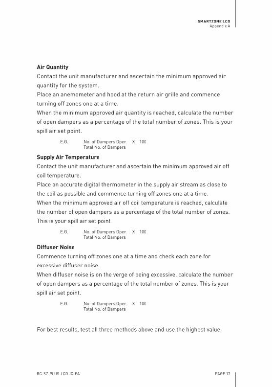
Air Quantity
Contact the unit manufacturer and ascertain the minimum approved air
quantity for the system.
Place an anemometer and hood at the return air grille and commence
turning off zones one at a time.
When the minimum approved air quantity is reached, calculate the number
of open dampers as a percentage of the total number of zones. This is your
spill air set point.
E.G. No. of Dampers OpenNo. of Dampers Open X 100 Total No. of Dampers
Supply Air Temperature
Contact the unit manufacturer and ascertain the minimum approved air off
coil temperature.
Place an accurate digital thermometer in the supply air stream as close to
the coil as possible and commence turning off zones one at a time.
When the minimum approved air off coil temperature is reached, calculate
the number of open dampers as a percentage of the total number of zones.
This is your spill air set point.
E.G. No. of Dampers OpenNo. of Dampers Open X 100 Total No. of Dampers
Diffuser Noise
Commence turning off zones one at a time and check each zone for
excessive diffuser noise.
When diffuser noise is on the verge of being excessive, calculate the number
of open dampers as a percentage of the total number of zones. This is your
spill air set point.
E.G. No. of Dampers OpenNo. of Dampers Open X 100 Total No. of Dampers
For best results, test all three methods above and use the highest value.

RC-SZ-PLUS-LCD-IC-EA
SMARTZONE LCDAppendix B
PAGE 18
Appendix B - Zone Weights (Low Profi le Model Only)
Overview
Making adjustments to the zone weight factor for each zone enables the
Smartzone’s spill/bypass algorithm to compensate for variations in zone size
when calculating when to begin opening the spill/bypass damper.
The default zone weight for each zone is 5, and by default, all zones are
treated equally when calculating the total percentage of open zones.
Consider the following simple example:
A Smartzone system is made up of two zones of equal size, with the
same zone weight. One zone is fully closed and one zone is fully open.
This is equal to the total system being 50% open.
If one of the zones is larger (one is twice the size of the other), but both
zones still have the same zone weight, the system would treat the large
zone being fully open and the small zone fully closed (Actual open = 67%),
exactly the same as the small zone being fully open and the large zone
fully closed (Actual open = 33%).
Evidently this disparity will have a dramatic effect on the operation of the
spill/bypass system.
By adjusting the zone weight for each zone, the system can be tuned to
ensure effective operation of the spill/bypass system.
In the example the following settings will have the desired effect.
Large zone weight = 10
Small zone weight = 5

RC-SZ-PLUS-LCD-IC-EA
SMARTZONE LCDAppendix B
PAGE 19
Methods for Calculating Zone Weight
Zone weights can be determined by utilising one or all of the following
methods:
a. Heat Load
b. Zone Area
The factory default zone weight for all zones is 5. Refer to page 10 for details
on how to adjust the zone weight for each zone.
Heat Load
Record the heat load (calculated at system design/unit selection stage) for
each zone in the table below.
Zone 1 Zone 2 Zone 3 Zone 4 Zone 5 Zone 6 Zone 7 Zone 8
Zone Heat Load (ZHL)
Zone Weight (ZW)
Zone weight factor (ZWF)
Now calculate the zone weight factor (ZWF) for the system by dividing 10 by
the highest zone heat load (ZHLmax).
E.G. ZWF = 10 ÷ ZHLmax
To determine the zone weight for each zone, multiply the heat load of each
zone by the zone weight factor and round to the nearest whole number.
E.G. ZW = ZHL x ZWF
Record the zone weight for each zone in the space provided.

RC-SZ-PLUS-LCD-IC-EA
SMARTZONE LCDAppendix B
PAGE 20
Zone Area
Calculate the area for each zone and record in the table below.
Zone 1 Zone 2 Zone 3 Zone 4 Zone 5 Zone 6 Zone 7 Zone 8
Zone Area (ZA)
Zone Weight (ZW)
Zone weight factor ( )
Now calculate the zone weight factor (ZWF) for the system by dividing 10 by
the largest zone area (ZAmax).
E.G. ZWF = 10 ÷ ZAmax
To determine the zone weight for each zone multiply the zone area of each
zone by the zone weight factor and round to the nearest whole number.
E.G. ZW = ZA x ZWF
Record the zone weight for each zone in the space provided.

RC-SZ-PLUS-LCD-IC-EA
SMARTZONE LCDAppendix C
PAGE 21
Appendix C - Troubleshooting Guide
PROBLEM POSSIBLE CAUSES / SUGGESTED ACTION
LCD touchpad is blank.Check the cable to touchpad. Check the 24VAC power supply from the transformer (If failed see next).
Transformer has failed
Prior to connecting the new transformer, verify the new transformer is capable of supplying 24V @ 48VA.Measure the current draw of the system at startup.If the current draw exceeds 48VA, disconnect immediatelyimmediatelyto prevent damage to the new transformer.Disconnect all touchpads and zone sensors.Re-apply power and measure the current draw of the transformer as the touchpad and sensors are re-connected one at a time to identify the problem connection (usually a cable fault).Re-terminate cable and repeat test to verify the problem has been rectifi ed.
Incorrect number of zones on the touchpad and the touchpad DIPswitches are set correctly.
Zone sensor/cable fault - open circuit.Check sensor cables for a bad connection. If room sensors are being used instead of room controllers, check the sensor box jumper, this should be in the “normal” position.
LCD touchpad displays Active:0 and I cannot turn it on. There is at least 1 good sensor connected & cabled correctly
Test the zone sensor inputs by plugging the supply air sensor into Zone 1 sensor input. If Zone 1 now appears on the display the problem is as per above.Check DIPswitch settings on the back of the touchpad as per Table 1 on page 13.If the fault persists with all DIPswitches OFF, check the connection between MPM and 1234 modules.
Continued next page ...

RC-SZ-PLUS-LCD-IC-EA
SMARTZONE LCDAppendix C
PAGE 22
PROBLEM POSSIBLE CAUSES / SUGGESTED ACTION
68 degrees displayed as a zone sensor reading
Room controller or Room sensor cable/crimp short circuit. Locate and correct
Dampers not driving.
Check the fault indicator LEDs at the motor output sockets (see next issue).Check the appropriate zone is turned ON.Check zone sensor reading is correct.Check the supply air temperature (refer to page 9-10 to access SA temp)Check cable connections and ensure crimp is correct.Check mechanical connection to actuator and damper.Check after a power outage to the MPM, all zone motors drive fully open, then drive to the correct regulating position. (Spill-bypass motor drives fully closed fi rst)
The red fault LED is on at the zone motor output socket.
There is a short somewhere in that zone motors cable, plugs or sockets (usually a cable fault). Check that the plugs are crimped correctly with no tiny shorts between the conductors.
Damper driving at the wrong time or temperature.
2 sensors cables are crossed over or 2 motor cables are crossed over. Locate and correct.
Incorrect zone operating as spill zone.
Check main processor module dipswitch settings. Turning any dipswitch on will make that zone become a spill zone. e.g. 6 on=zone 6. Check that the bypass socket is not in fault mode if being used.
Continued next page ...
RC-SZ-PLUS-LCD-IC-EA
SMARTZONE LCDAppendix C
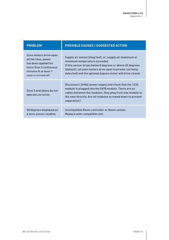
PAGE 23
PROBLEM POSSIBLE CAUSES / SUGGESTED ACTION
Zone motors drive open all the time, power has been applied for more than 3 continuous minutes & at least 1 zone is turned off.
Supply air sensor/plug fault, or, supply air maximum or minimum temperature exceeded.If this sensor drops below 8 degrees or above 65 degrees (default), all zone motors drive open (extreme coil temp detected) and the optional bypass motor will drive closed.
Zone 5 and above do not operate correctly.
Disconnect 24VAC power supply and check that the 1234 module is plugged into the 5678 module. There are no cables between the modules, they plug from one module to the next directly. Are all modules screwed down to prevent separation?
58 degrees displayed as a zone sensor reading
Incompatible Room controller or Room sensor. Replace with compatible unit.

Designed and manufactured in Australia byInnovative Air Systems Pty Ltd
Product SupportFreecall 1800 354 [email protected]
Sales Phone: 1300 306 [email protected]
System Installed by:
_____________________________________________________________
_____________________________________________________________
_____________________________________________________________
Date Installed:
_____________________________________________________________
_____________________________________________________________
For service, faults and diffi culties please contact:
_____________________________________________________________
_____________________________________________________________
_____________________________________________________________
Related Documents