Documentation SDL Core Documentation Document current as of 03/21/2018 12:43 PM. Core Documentation In the Core documentation you will find information about the architecture of the SDL embedded component (SDL Core), as well as information on how to customize this application to work well with your vehicle. First of all, the SDL Core SW Architecture document provides an overview the SDL Core application as well as the SDL platform. For Integration purpose, please follow: • Deployment schema • Operational aspects ◦ Configuration ◦ Logging ◦ Diagnostics • Preloaded Policy Table configuration For Testing purpose, please follow: • Logging and diagnostics • Automated Test Framework (ATF) SW Architecture

Welcome message from author
This document is posted to help you gain knowledge. Please leave a comment to let me know what you think about it! Share it to your friends and learn new things together.
Transcript

Documentation SDL CoreDocumentationDocument current as of 03/21/2018 12:43 PM.
Core Documentation
In the Core documentation you will find information about the architecture of
the SDL embedded component (SDL Core), as well as information on how to
customize this application to work well with your vehicle.
First of all, the SDL Core SW Architecture document provides an overview the
SDL Core application as well as the SDL platform.
For Integration purpose, please follow:
• Deployment schema• Operational aspects
◦ Configuration◦ Logging◦ Diagnostics
• Preloaded Policy Table configuration
For Testing purpose, please follow:
• Logging and diagnostics• Automated Test Framework (ATF) SW Architecture

Table of contents
• 1. Introduction
◦ 1.1. Purpose and Scope of the SAD◦ 1.2. Definitions and Abbreviations◦ 1.3. Document Roadmap
• 2. Case Background
◦ 2.1. System Context, Mission and Scope◦ 2.2. Product Stakeholders◦ 2.3. Business Goals◦ 2.4. Significant Driving Requirements
• 3. Solution Overview• 4. Views
◦ 4.1. Use Case View◦ 4.2. Components View◦ 4.3. Component Interaction View
▪ 4.3.1. Transport layer▪ 4.3.2. Protocol layer▪ 4.3.3. Business layer
◦ 4.4. User Interface◦ 4.5. Data View◦ 4.6. Process State View◦ 4.7. Process View◦ 4.8. Development View
▪ 4.8.1. Implementation Technologies▪ 4.8.2. Modules and Code Base Organization▪ 4.8.3. Development Environment and Standards
◦ 4.9. Deployment View◦ 4.10. Operational View

• 5. View-to-View Relations
◦ 5.1. Component-to-Layer◦ 5.2. Data-to-Layer View
• 6. Solution Background
◦ 6.1. Architecture Design Approach◦ 6.2. Requirements Coverage◦ 6.3. Prototyping Results◦ 6.4. Open Questions and Known Issues◦ 6.5. Results Analysis
• 7. References• 8. List of Figures• 9. Appendices• 10. History
1. Introduction
1.1. Purpose and Scope of the SAD
This document defines the high-level software architecture for the
SmartDeviceLink (SDL) system. It describes the structure and the main
components of the system, the project basis and dependencies. The goal of the
document is to describe, in sufficient detail, the software components, their
responsibilities, behavior, and interfaces. This document provides support for
Luxoft, Ford, open-source developers and others to learn system design,
limitations, stakeholders, and ways of extension and further development.
1.2. Definitions and Abbreviations
Abbreviations used in this document please find in the table below.

A B B R E V I AT I O N E X PA N S I O N
Definitions used in this document are in the table below.
D E F I N I T I O N D E S C R I P T I O N
BT Bluetooth
GUI Graphical User Interface
HMI Human Machine Interface
IVI In-Vehicle Infotainment
RPC Remote Procedure Call
SDE Software Development Environment
SDL SmartDeviceLink
SEE Software Engineering Environment
TTS Text To Speech
VR Voice Recognition
Concern A functional or non-functionalrequirement.
Model
A particular diagram or descriptionconstructed following the methoddefined in a viewpoint. These provide thespecific description of the system, whichcan include identifiable subsystems andelements.
StakeholderAn individual, group or organization thathas at least one concern relating to thesystem.

1.3. Document Roadmap
The SW architecture of system is considered from different viewpoints:

V I E W P O I N T V I E W P O I N T D E S C R I P T I O N
ComponentFunctional type of view which describesthe system's runtime functional elementsand their responsibilities.
Component Interaction
Functional type of view which describesinteractions of the system's functionalelements. Component Interaction viewuses component-level sequence orcollaboration diagrams to show howspecific components will interact. Thepurpose is to validate structural designvia exploration of the software dynamics.
Use Case
Use Case View captures systemfunctionality as it is seen by users.System behavior, that is whatfunctionality it must provide, isdocumented in a use case model.
User InterfaceFunctional type of view which describesinterfaces of the system's functionalelements.
Data
Describes the way that the systemstores, manipulates, manages, anddistributes information. The ultimatepurpose of virtually any computersystem is to manipulate information insome form, and this viewpoint developsa complete but high-level view of staticdata structure and information flow. Theobjective of this analysis is to answer thequestions around data content, structure,ownership, quality, consistency updatelatency, references, volumes, aging,retention, and migration.
Process State
Concurrency type of view. Process StateView is used to model standard processdynamics that are independent of theloaded components. These dynamicsmay, for example, be part of acomponent management infrastructurethat loads and controls components inthe process. For process dynamics, it isoften useful to think in terms of astandard set of states such as initializing,operating, and shutting down
Process
Concurrency type of view. Process Viewdescribes processes and process inter-communication mechanismsindependent of physical hardwaredeployment
Development
Describes the architecture that supportsthe software development Process. Thisview addresses the specific concerns ofthe software developers and testers,namely code structure anddependencies, build and configurationmanagement of deliverables, designconstraints and patterns, and namingstandards, etc. The importance of thisview depends on the complexity of thesystem being built, whether it isconfiguring and scripting off-the-shelfsoftware, writing a system from scratch,or something between these extremes.

V I E W P O I N T V I E W P O I N T D E S C R I P T I O N
For more information about Viewpoints refer to Architectural Blueprints The “4
+1” View Model of Software Architecture:
- http://www.cs.ubc.ca/~gregor/teaching/papers/4+1view-architecture.pdf.
For detailed UML diagrams notation description please refer to :
- http://www.uml-diagrams.org/
- https://sourcemaking.com/uml
2. Case Background
2.1. System Context, Mission and Scope
SmartDeviceLink system is developed to serve as a proxy between vehicle
Head Unit sub-system and an Application that runs at any of compatible Mobile
Devices:
• A Mobile Device might be connected via USB, Bluetooth or Wi-Fi to the HU;• The Application should be the SDL-enabled one.
Deployment
Describes the environment into whichthe system will be deployed and thedependencies that the system has onelements of it. This view captures thehardware environment that your systemneeds (primarily the processing nodes,network interconnections, and diskstorage facilities required), the technicalenvironment requirements for eachelement, and the mapping of thesoftware elements to the runtimeenvironment that will execute them.
Operational
Describes how the system will beoperated, administered, and supportedwhen it is running in its productionenvironment. The aim is to identifysystem-wide strategies for addressingthe operational concerns of the system'sstakeholders and to identify solutionsthat address these
Logical
Logical view focuses on the functionalneeds of the system, emphasizing on theservices that the system provides to theusers. It is a set of conceptual models.

The Mobile Device might be any of:
- Smartphone devices
- Tablet PCs
with operational system:
- iOS
- Android.
The SDL system allows Application to:
- Use vehicle HMI: VR, TTS, buttons (physical and touch-screen), vehicle display,
audio system. etc.
- Retrieve Vehicle Data (seat belt position, transmission shift lever position,
airbag status, etc.).
2.2. Product Stakeholders
Actors are stakeholders that interact with product directly.
S TA K E H O L D E R N A M E A C T O R ( Y E S / N O ) C O N C E R N
2.3. Business Goals
Luxoft delivered to Ford a prototype of POSIX compliant Applink Core in March,
2013.
To support FORD goal of successful acceptance of Applink (new name is
SmartDeviceLink) Core by open source community of GENIVI consortium further
enhancements will be required. The purpose of the project is to develop
Ford Company No
Get the SDL system withenough quality andfunctionality that fulfilltheir goals
PM / Architect / Analyst NoUse CustomerRequirementsSpecification
Developers YesConstruct and deploythe system fromspecifications
Testers NoTest the system toensure that it is suitablefor use

component of SmartDeviceLink 4.x Core by adding new features required by
Ford.
2.4. Significant Driving Requirements
The requirements are listed in the table below and ordered by descending of
their significance from architectural solution point of view.
#D R I V I N G R E Q U I R E M E N TD E S C R I P T I O N
3. Solution Overview
The picture below shows SmartDeviceLink technology overview.
SEQUENCE DIAGRAM
1.System has to be POSIX-compliant to beeasily ported on all POSIX standardizedOSs.
2.
Transport for communication betweenMobile Application and SDL system mustbe implemented and easily changed,replaced or added if required
3.
APIs for communication between MobileApplication and SDL system described inappropriate documents have to be fullysupported by the system.
4.There has to be relatively easy way toport existing HMI Modules (such as UI,VR, TTS, etc.) to work with SDL system.
5.
APIs for communication between SDLsystem and HMI Modules have to be fullydescribed in appropriate document andfully supported by SDL system.
SOLUTION OVERVIEW
View Diagram

4. Views
4.1. Use Case View
The following Use Case diagrams show the actors, the processes and their
interactions within SDL System.
OVERVIEW USE CASE DIAGRAM

DISCONNECT USE CASE DIAGRAM
CONNECTION USE CASE DIAGRAM

SERVICE DATA TRANSFERRING USE CASE DIAGRAM

ENCRYPTION USE CASE DIAGRAM

DATA VERIF ICATION USE CASE DIAGRAM
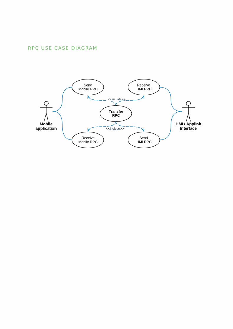
RPC USE CASE DIAGRAM

MOBILE TO HMI RPC PROCESSING USE CASE DIAGRAM
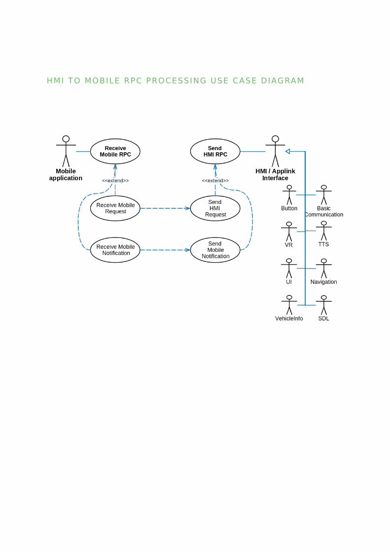
HMI TO MOBILE RPC PROCESSING USE CASE DIAGRAM

RESUMPTION USE CASE DIAGRAM

APPLICATION DATA RESUMPTION USE CASE DIAGRAM

4.2. Components View
The view is represented by module and subsystem diagrams that show the
system's export and import relationships. The Components View diagram and
its elements description please see below.
Note: UML notation for this Components View diagram is extended: both
component and it's interfaces are highlighted with the same colour.
SEQUENCE DIAGRAM
HMI LEVEL RESUMPTION USE CASE DIAGRAM

C O M P O N E N T V I E W D I AG RA M
Elements description
View Diagram

Utility components:
• Responsibility:
◦ Functional components manipulation ◦ creation◦ destruction ◦ initialization◦ start, stop ◦ binding ◦ System and Utils-specifics initialization ◦ Relations◦ Composes all available components
• Interfaces
◦ Does not provide any external interfaces
• Behavior
◦ Life Cycle creates all available in system components according
configuration, binds components to components and starts each
component internal routines.
• Constraints
◦ N/A
• Responsibility
◦ Storing information about application configuration.
L IFE CYCLE
CONFIG PROFILE

• Relations
◦ Used by Life Cycle for filling other components Settings
• Interfaces
◦ Provides Profile interface
• Behavior
◦ Config Profile parses configurable data storage and provides
primitive types by section and name of configurable value.
• Constraints
◦ Configuration format - INI file.
• Responsibility
◦ Encapsulation system low-level functionality.
• Relations
◦ Used by all components.
• Interfaces
◦ Logger macros-es and functions ◦ Data and Time◦ Files◦ Thread and Timer◦ Locks and ConditionalVariable classes◦ CustomString class for UTF8 string handling
• Behavior
◦ Utils behavior relates to system-specific API.
• Constraints
◦ N/A
UTILS
HMI layer components:
• Responsibility
◦ Formatting message to and from unified protocol-API-independent
format used by higher-level component.◦ Providing adapters for different transport types between SDL and
HMI.
• Relations
◦ Application Manager◦ Utils
• Interfaces
◦ HMIMessageObserver interface for listening HMI messages
notification◦ HMIMessageSender interface for sending Messages◦ HMIMessageAdapter interface for abstracting to-HMI transport◦ HMIMessageHandler interface for accumulating
HMIMessageObserver, HMIMessageSender and
HMIMessageAdapter
• Behavior
◦ Transferring RPC Messages between business-layer and configured
transport.
• Constraints
◦ Processes messages from a single instance of HMI only.
HMI MESSAGE HANDLER

◦ HMI-transport need to be statically configurable with build flags.
Business layer components:
• Responsibility
◦ Storing and providing mobile-related information◦ Mobile application state manipulation
• Relations
◦ Uses Commands◦ Uses MediaManager◦ Requires HMIMessageObserver* and HMIMessageSender (HMI
Message Handler)***◦ Requires PolicyHandler* and PolicyHandlerObserver (Policy)***◦ Requires ProtocolHandler* and ProtocolObserver (Protocol
Handler)***◦ Requires ConnectionHandler* and ConnectionHandlerObserver
(Connection Handler)***◦ Requires SessionObserver (Connection Handler)◦ Requires SecurityManagerListener (Security Manager
component)
• Interfaces
◦ Provides ApplicationManager interface
• Behavior
◦ The component implements business logic of the SDL.
• Constraints
◦ N/A
APPLICATION MANAGER

• Responsibility
◦ Mobile and HMI RPC data verification according to business-
requirements◦ Transferring Mobile RPC Requests to HMI subsystems (UI, VR, TTS
and other available ones) and HMI to Mobile Responses and
Notifications
• Relations
◦ Created by ApplicationManager◦ Composed by RequestController
• Interfaces
◦ Provides Command interface
• Behavior
◦ Mobile Requests are spitted between responsible HMI interfaces and
sent as separate HMI Requests or Notifications.◦ HMI Responses and notifications are verified according to business
requirements and provided to Mobile.
• Constraints
◦ FORD Mobile API Spec◦ FORD HMI API Spec◦ Commands happy paths are depends on correct HMI Behavior
implementation.
• Responsibility
◦ Pending requests handling
COMMANDS
REQUEST CONTROLLER

◦ Optimization threads count for handling large quantity of pending
RPCs
• Relations
◦ Composes Commands◦ Composed by Application Manager
• Interfaces
◦ Provides Request Controller interface
• Behavior
◦ Request Controller handles timeout of responses and notifications
from HMI.
• Constraints
◦ Configurable count of threads usage.
• Responsibility
◦ Launch known applications on devices.
• Relations
◦ Composed by Application Manager ◦ Use Resume Controller interface to get HMI level of saved
application.
• Interfaces
◦ Provides App Launch Controller interface
• Behavior
◦ App Launch launch all known applications on newly connected
device.
APP LAUNCH

• Constraints
◦ Not work for Android apps.◦ Not work for apps connected via SDL protocol version lower than 4.
• Responsibility
◦ Loads all .so files from specific directory, checking if they’re
exporting required methods◦ Stores information about plugin capabilities◦ Checks plugins capability to handle RPCs
• Relations
◦ Composed by Application Manager ◦ Composes Plugin
• Interfaces
◦ Provides Plugin Manager interface
• Behavior
◦ Loads and manages plugins from specific directory.
• Constraints
◦ Able to load only RPC layer plugins
• Responsibility
◦ Restoring application data◦ Storing application and HMI-related data between shutdown cycles
• Relations
◦ Composed by Application Manager
PLUGIN MANAGER
RESUMPTION

• Interfaces
◦ Provides Resume Controller interface
• Behavior
◦ Resumption backs up application and HMI-related data and restores
it after SDL start-up according to business logics.
• Constraints
◦ Configurable data storage type.
• Responsibility
◦ Enabling advanced SDL functionality◦ SDL APIs protection from unauthorized application usage◦ Remotely manage SDL-enabled apps, including app-specific and
device-specific access to system functionality◦ Maintain applications permissions on the system
• Relations
◦ Uses ApplicationManager interface for mobile application state
manipulation
• Interfaces
◦ Provides PolicyManager interface for policy data manipulation◦ Provides PolicyListener interface for policy notification subscribing
• Behavior
◦ Receives data from Application manager◦ Parses data- Stores in local storage◦ Provides data via Application Manager to mobile device and HMI and
vice-versa
POLICY

• Constraints
◦ Needs to be a switchable components: dynamically by configuration
file and statically by SDL build define.
• Responsibility
◦ Audio and Video data transferring to Media sub-system◦ Encapsulation binary data transferring transport
• Relations
◦ Used by Application Manager
• Interfaces
◦ Provides MediaManager interface
• Behavior
◦ Media Manager transfers raw Audio and Video data through one of
the Media-adapters.
• Constraints
◦ Configurable Media-adapter usage
• Responsibility
◦ Allows incorporating additional functionality to the core application
by application extension.◦ Implements specific mobile RPC handling.◦ Implements specific HMI RPC handling.
• Relations
◦ Composed by Plugin manager
MEDIA MANAGER
REMOTE CONTROL

◦ Handles Application Manager by Service interface
• Interfaces
◦ Provides Plugin Manager interface
• Behavior
◦ Receives data from CoreService◦ Parses data◦ Creates commands.◦ Handles incoming HMI notifications◦ Sends RPC to HMI◦ Sends RPC to mobile◦ Extends basic applications with additional RPC's
• Constraints
◦ N/A
Protocol layer components:
• Responsibility
◦ Control and business data distributing to appropriate sessions and
service◦ Control message processing◦ Multi-frames assembling and disassembling◦ Malformed packets determination and filtering
• Relations
◦ Notifies ConnectionHandler about connection and session state
change◦ Uses SecurityManager for encryption and decryption payload data
PROTOCOL HANDLER

• Interfaces
◦ Provides ProtocolHandler interface for data sending and protocol
layer manipulation◦ Provides ProtocolObserver notification for subscription on protocol
events.
• Behavior
◦ Decodes income raw transport data and encodes outcome RPCs
according to protocol specification.
• Constraints
◦ SmartDeviceLink Protocol specification
• Responsibility
◦ Storing devices and connection information◦ Manage starting and ending of sessions◦ Providing device, connection and session information for protocol
and business layer◦ Manipulation with devices, connections and sessions◦ Negotiation and monitoring the availability of device connections
(heartbeat)
• Relations
◦ Requires ProtocolHandler for sending Control messages related to
session life cycle◦ Requires TransportManager for forwarding business layer device
and connection manipulations
• Interfaces
◦ Provides ConnectionHandller interface for connection manipulation◦ Provides SessionObserver interface for session information
manipulation
CONNECTION HANDLER

• Behavior
◦ Connection Handler works as a proxy from business-layer to
transport layer and provides additional information related to
protocol sessions and services.
• Constraints
◦ SmartDeviceLink Protocol specification
• Responsibility
◦ Data encryption and decryption◦ TLS Handshake negotiation◦ TLS Library dependency encapsulation
• Relations• Uses SessionObserver for setting Security information to sessions• Uses ProtocolHandler and ProtocolObserver for handling TLS
handshake data • Interfaces
◦ Provides SecurityManager interface for Security component◦ Provides SecurityManagerListener interface for notification
handshake event◦ Provides SSLContext interface for data encryption and decryption
• Behavior
◦ Security Manager provides methods to establish encrypted
connection to mobile.
• Constraints
◦ Needs to be a switchable components: dynamically by configuration
file and statically by SDL build define.◦ SmartDeviceLink Protocol specification
SECURITY MANAGER

Transport layer components:
• Responsibility
◦ Manages low-level connections from Mobile Applications◦ Transport devices and connections manipulation◦ Performs device discovery◦ Sending and receiving mobile messages
• Relations
◦ Composes TransportAdapters according to configuration
• Interfaces
◦ Provides TransportManager interface for devices and connections
status manipulation◦ Provides TransportManagerListener interface for transport
notification subscribing
• Behavior
◦ Accumulative class for all available in system devices and
connections.
• Constraints
◦ N/A
• Responsibility• Transport-specific API encapsulation• Relations
◦ Composed by TransportManager
TRANSPORT MANAGER
TRANSPORT ADAPTER

• Interfaces
◦ Provides TransportAdapters interface
• Behavior
◦ Adopts transport searching, connecting, data transferring API for one
TransportAdapters interface.
• Constraints
◦ For Bluetooth BlueZ transport there are only 30 connections
available due to RFCOMM channels limitations.◦ Transport Manager Programming guide
4.3. Component Interaction View
According to layer architectural approach (see chapter 6.1), Component
Interaction View could be split to Transport, Protocol and Business layer
diagrams.
4.3.1. Transport layer
Behavior:
All device notifications are transferred through the Transport Adapter,
accumulated by Transport Manger and provided for the upper levels with an
unique device and connection identifier.
SEQUENCE DIAGRAM
Transport layer notification and data
transferring diagram

4.3.2. Protocol layer
Behavior:
Protocol layer is responsible for transferring Transport and Protocol events to
the Business layer.
SEQUENCE DIAGRAM
Protocol Layer - transport notifications
processing diagram
View Diagram
View Diagram

SEQUENCE DIAGRAM
Protocol Layer - data transferring diagram
View Diagram

4.3.3. Business layer
Behavior:
Business layer is responsible for processing all income and outcome RPC data
and media data streaming.
SEQUENCE DIAGRAM

Business layer - media data transferring
diagram
SEQUENCE DIAGRAM
Business layer - RPC processing diagram
View Diagram
View Diagram


SEQUENCE DIAGRAM
Business layer - App Launch
SEQUENCE DIAGRAM
Business layer - Plugin Manager
View Diagram
View Diagram

4.4. User Interface
Not applicable, since the User Interface is not the part of development.
4.5. Data View
The Data View shows relations between separated data types and actors that
perform information processing in the system. It depicts contents of saved
information and also visualizes information sources, processors and destination.
The following Diagram shows relations between separated data types and
actors that perform information processing in the SmartDeviceLink.
SEQUENCE DIAGRAM

DATA F LO W D I AG RA M
View Diagram

Elements description
• Summary:
◦ Stores raw data with connection identifier.
• Usage:
◦ Data primitive in Transport Manager◦ Used by Protocol Handler as a transport layer income data,
connection_key identifies physical connection◦ Used by Protocol Handler as a business layer outcome data,
connection_key identifies unique session
• Summary:
◦ Protocol layer primitive with protocol related information.
• Usage:
◦ Used internally by Protocol Handler for protocol header information
prepossessing
• Summary:
◦ Security Manager primitive type.
• Usage:
◦ Encapsulates TLS handshake and security error data
RAWMESSAGE
PROTOCOLFRAME
SECURITYQUERY

• Summary:
◦ Application Manager RPCs primitive type with function and
correlation identifiers.
• Usage:
◦ Internally by Protocol Handler for protocol header information
prepossessing◦ As abstraction for RPCs transferring by HMI Message Helper
• Summary:
◦ SmartObject acts as a union for business-layer data and could
handle RPCs data as one hierarchy object.
• Usage:
◦ Used by Application Manager, Commands and HMI Message Helper
for RPCs data filling◦ RPC's data transferring between business-layer components ◦ Note: SmartObjects are being validated according to MOBILE_API.xml
and HMI_API.xml.
• Summary:
◦ RPCs objects with validation and processing data according to
business requirements
MESSAGE
SMARTOBJECT
MOBILE COMMAND AND HMI COMMAND

• Usage:
◦ Application Manager prepares Mobile Requests according to
SmartObjects from transport layer◦ Mobile Request prepares SmartObject for the next HMI Request
object and subscribes to answer event◦ Application Manager prepares HMI Response according to
SmartObjects from HMI layer◦ HMI Request prepares SmartObject for the next HMI Request object
• Summary:
◦ Json library abstraction
• Usage:
◦ Used as a primitive for JSON format in HMI transport
• Summary:
◦ DBUS message system abstraction
• Usage:
◦ Used as a primitive for DBUS format in HMI transport
4.6. Process State View
The process State view shows the global SmartDeviceLink states according to
system life cycle.
JSON::VALUE
DBUS MESSAGE

SEQUENCE DIAGRAM
L I F E CYC L E S TAT E S D I AG RA M
Elements description
• Behaviour:
◦ SDL creates and initializes component according to configuration file.
• Relations:
◦ If all SDL subsystems successfully started, SDL starts waiting HMI
and mobile connections.◦ If failed, SmartDeviceLink is shutting down.
IN IT IALIZATION
View Diagram

• Behaviour:
◦ SDL waits for an HMI connection.
• Relations:
◦ If HMI successfully connected, SDL starts processing all mobile
data.◦ On receiving stop signal SmartDeviceLink is shutting down.
• Behaviour:
◦ SDL handles HMI and mobile data and proceed according to business
requirements.
• Relations:
◦ SDL starts shutdown procedure on getting stop signal from HMI or
OS.
• Behaviour:
◦ SDL stores all resumption data, unregisters all mobile applications,
disconnects from HMI and denitializes all components.
• Relations:
◦ Finish SDL life cycle,◦ Continue processing data on getting Awake command from HMI.
HMI CONNECTION
PROCESSING DATA
SHUTTING DOWN

4.7. Process View
Not applicable, since the developed system works within one process.
4.8. Development View
4.8.1. Implementation Technologies
• C++98 language is selected as a programming language for
SmartDeviceLink as a OS and CPU architecture independent.• CMake tool-chain selected as a cross-platform building tools.• Google Test with Google Mock extension is chosen as an opensource C++
test framework.
4.8.2. Modules and Code Base Organization
Development view organizes SmartDeviceLink components into logical and
abstract groups called layers. The layers describe the major tasks that the
components perform. The layers have different responsibilities and different
providers

D E V E LO P M E N T V I E W D I AG RA M
Elements description
• Responsibility
◦ Providing high-level interface for OS and hardware resource
manipulation.
• Relations:
◦ Used by all other layers
• Interfaces:
◦ Provides threads, timers, synchronization, data, time, file and logging
interfaces
• Behavior:
◦ Wrapping all OS-system-specific API to C++ Objects.
OS LAYER

• Constraints:
◦ N/A
• Responsibility
◦ Encapsulates mobile and HMI transports usage
• Relations:
◦ Protocol layer
• Interfaces:
◦ TransportManager◦ HMIMessageHandler
• Behavior:
◦ Opens connection◦ Performs device discovery◦ Sends / receives messages
• Constraints:
◦ Transport Manager Programming guide
• Responsibility:
◦ Encapsulates protocol manipulation.
• Relations:
◦ Application layer◦ Transport layer
TRANSPORT LAYER
PROTOCOL LAYER

• Interfaces:
◦ ProtocolHandler◦ ConnectionHandler ◦ SecurityManager
• Behavior:
◦ Parses and handles messages from transport layer according to
Protocol ◦ Notify upper level about new transport and protocol layer events◦ Provides Transport Layer manipulation by upper layers
• Constraints:
◦ SmartDeviceLink Protocol specification
• Responsibility:
◦ Represents main business logic implementation
• Relations:
◦ Protocol Layer
• Interfaces:
◦ ApplicationManager◦ MediaManager◦ Command◦ RequestController◦ App Launch◦ Resumption◦ Plugin Manager◦ Policy
• Behavior:
◦ Main business logic functionality.
APPLICATION LAYER

• Constraints:
◦ FORD Mobile API Spec◦ FORD HMI API Spec
4.8.3. Development Environment and Standards
• Development and testing environment for Ubuntu 14.04 LTS x32/x64
◦ Debug Environment: Ubuntu 14.04 LTS x32/x64, Qt 5.3◦ Compiler: GCC 4.9.3 (OS Ubuntu), Lua 5.2◦ Build system: Cmake 2.8.12.2
• Development and testing environment for SDL Windows x64:
◦ Build system: Windows 7 x64, CMake◦ Compiler: Microsoft Visual Studio Express Edition 2013 x64
• Development and testing environment for SDL Qt for Windows x32:
◦ Build system: Windows 7 x32, Qt 5.5, CMake, QT Creator◦ Compiler: Microsoft Visual Studio Express Edition 2010 x32
• Requirements Management system: LuxProject (JIRA, Confluence)• Source Control System: GitHub• Issue Tracking System: LuxProject (JIRA)• Document Management System: LuxProject (JIRA, Confluence, SVN)• Coding style: SDL C++ Style
4.9. Deployment View
The deployment view takes into account the system's requirements such as
system availability, reliability (fault tolerance), performance (throughput), and
scalability. This view maps the various elements identified in the logical,
process, and development views—networks, processes, tasks, and objects—
onto the processing nodes.
The deployment diagram is used for modeling the static deployment view of a

system.
The figure below depicts the deployment diagram for SDL system.
SEQUENCE DIAGRAM
D E P LOY M E N T V I E W D I AG RA M
Elements description
• Short Description:
◦ The SDL application model permits multiple applications to be
concurrently active and connected to the HU.◦ A few of those applications may interact with the user at a time
using the HMI (depending on HMI).
MOBILE DEVICE
View Diagram

◦ SDL uses the concept of HMI Levels to describe the current state of
the application with regards to the level at which the head unit can
communicate with it (and vice versa).
• Relations:
◦ Receives policies updates from Cloud Server◦ Sends statistics to Cloud Server.
• Requirements:
◦ Android OS or iOS.
• Short Description:• HU HMI allows the user/driver to interact with the vehicle.
◦ This interface includes:◦ A set of presets◦ Media buttons (seek forward/backward, tune up/down, and play/
pause)◦ Menu items◦ Graphic user interface◦ Voice commands, etc.
• The HU HMI Handler interfaces with SDL Core to support the API
functionality. • Relations:
◦ Communicates with applications on Mobile Device
HEAD UNIT

• Requirements:
◦ N/A
• Short Description:
◦ A Server that provides information about:◦ Which applications are allowed to run in vehicle ◦ What interfaces application is allowed to use. ◦ In addition, server provides:◦ System configuration, including the time of the next file update◦ Some important server information to the back end user
• Relations:
◦ Sends policies updates to Mobile Device.◦ Receives statistics from Mobile Device.
• Requirements:
◦ N/A
4.10. Operational View
This view describes how the architecture provides the ability for operation/
support teams to monitor and manage the system. To make system more
flexible and to support different platforms, SW provides a configuration and
CLOUDSERVER

logging components, which are able to change system behavior according to
settings defined in smartDeviceLink.ini file and to diagnostic.
Config Profile component specifies the desirable system behavior on different
platforms and provides settings parameters for each functional component or
functionality:
• Mobile and HMI transports connection• Protocol, Connection, Security• Policy, Resumption• File system restrictions• Global properties like HelpPrompt, TimeoutPrompt, HelpTitle,
HelpCommand• Default Timeout for mobile application commands• Desirable location of the system data (log files, persistence data,
temporary data)
For further information with a list of all available parameters please refer to
chapter "15.1 SDL’s configuration file structure" of HMI Guideline or
smartDeviceLink .ini file.
SDL logging system (with a log4cxx library for posix build) provides powerful
flexibility and allows to configure SDL for development, integrator and user
SDL CONFIGURATION
LOGGING CONFIGURATION

purposes by changing log4cxx property file
Each SDL component can be configured with own:
• Logging level output
◦ Example: for user needs using Warning+ level is preferable for all
OSm Transport and Protocol layers components.
• Output source appender
◦ SDL (with Log4cxx) can log to the console, files, remote socket
servers, NT Event Loggers, remote UNIX Syslog daemons and others.
• own output log pattern
For further information about configuration please refer:
• log4cxx HowTo• Configuring loggers
SmartDeviceLink system provides diagnostics messages log file with following
types of messages:
• FATAL message indicates abnormal problem related to external
subsystems contract violation or SDL implementation issues. It indicates
some critical issue and all SDL behaviors is undefined after this message.• ERROR message shows, that the problem occurred and SDL has not
accomplished some internal or API activities. Error is successfully handled
by SDL, but notifies about some business logic's flow breakdown. • WARNING message warns against uncommon or rare flow. This message
indicates handling some expected by SDL issue according to specified
requirements.• INFO informs SDL user, integrators or support engineer about the
component high-level activity success.• DEBUG and TRACE messages contain debug information for software
engineer diagnostics and deep issues analysis.
DIAGNOSTICS

For further information about logging levels usage please refer related article.
5. View-to-View Relations
Each of the views specified in Section 3 provides a different perspective and
design handle on a system, and each is valid and useful in its own right.
Although the views give different system perspectives, they are not
independent. Elements of one view will be related to elements of other views,
and we need to reason about these relations.
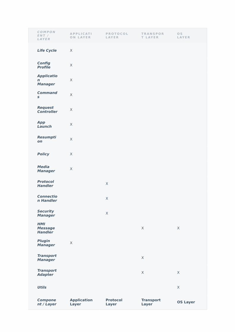
5.1. Component-to-Layer
The following table is a mapping between the elements in the Component view
and the Development view. The relationship shown is is-implemented-by, i.e.
the layers from the Development view shown at the top of the table are
implemented by any selected elements from the Component view, denoted by
an "X" in the corresponding cell.
C O M P O NE N T /L AY E R
A P P L I C AT IO N L AY E R
P R O T O C O LL AY E R
T R A N S P O RT L AY E R
O SL AY E R
Life Cycle X
ConfigProfile X
ApplicationManager
X
Commands X
RequestController X
AppLaunch X
Resumption X
Policy X
MediaManager X
ProtocolHandler X
Connection Handler X
SecurityManager X
HMIMessageHandler
X X
PluginManager X
TransportManager X
TransportAdapter X X
Utils X
Component / Layer
ApplicationLayer
ProtocolLayer
TransportLayer OS Layer

5.2. Data-to-Layer View
The following table is a mapping between the elements in the Data view and
the Development view. The relationship shown is is-implemented-by, i.e. the
layers from the Development view shown at the top of the table are
implemented by any selected elements from the Component view, denoted by
an "X" in the corresponding cell.
D ATA /L AY E R
A P P L I C AT IO N L AY E R
P R O T O C O LL AY E R
T R A N S P O RT L AY E R
O SL AY E R
Message X
SmartObject X
MobileCommand X
HMICommand X
ProtocolFrame X
SecurityQuery X
RawMessage X X X
JSON::Value X X
DBUSmessage X X

6. Solution Background
6.1. Architecture Design Approach
During the architecture designing the following aspects and rules were primary
considered:
1. Three-layer architectural approach: Transport (low), Protocol (middle),
Application (high) layer.
1. Each layer component uses only own or low layer interfaces2. Observer design pattern is required for providing information for
upper layer components.
2. Weak components and classes coupling for providing
SmartDeviceLink Extensibility.
1. Providing each component and class functionality with an interface.2. Facade design pattern is used for Mobile and HMI transports
functionality within one interface.3. Observer interface for providing information for upper layer
components.4. Binding different layers components is in LifeCycle component
responsibility.
3. System scalability for adding new interrogation platform transport.
1. Adapter design pattern is used to provide permanent interface to
transport layer.2. Abstract Factory design pattern is used to create related objects
without specifying their concrete classes directly.3. Command design pattern is used to treat requests as an object that
provides possibility to add new request without existing code
modification.

4. OS and hardware abstraction for simplifying portability to non-POSIX-
compliant OS.
1. Adapter pattern is used for preparing the cross-platform interface for
thread, timer, synchronization, file and data access functionality.2. For HMI and Mobile transports used adapter pattern with a unified
interface, which could be reused for new platform- and OS- specific
transport API adoption3. OS-related and 3d-party libraries APIs are segregated in Utils
component, which available for all SDL layers 4. Utils classes are implemented with Bridge design pattern (PIMPL
idiom) for avoiding platform and 3d-party libraries dependencies.
5. Asynchronous data and notification handling for meeting real time
restrictions on transport layer and providing vertical scalability.
1. Different data-types processing preferable in separate threads.2. For internal data processing components preferable to use
Utils::threads::MessageLoopThread for the same data objects
processing
▪ Asynchronous call result has to be provided with Observers
interfaces to callee
3. For transport API adapters preferable the own Utils::threads::Thread
implementation for meeting realtime restrictions4. SmartDeviceLink logging implemented with
Utils::threads::MessageLoopThread for avoiding console, file and
other appends delay affect on functionality5. For pending large number processing RPCs selected Controller
design pattern with a limited and configurable count of processing
threads
6. Resource Acquisition Is Initialization (RAII, or Scope-based Resource
Management) for memory, mutex, files and other resources management.
1. utils::SharedPtr template class is implemented for memory
deallocation.2. utils::AutoLock is implemented for mutex acquiring and releasing 3. utils::ScopeGuard is implemented for external memory and resource
deinitialization.

7. Strict heap memory usage for avoid memory leaks and memory
corruption.
1. SmartDeviceLink objects aggregation is preferable by reference link
storing instead of raw pointer,
▪ Note: in case external class life-time guaranty.
2. System objects composition is preferable by value or by smart
pointer:
1. In case of exclusive object handling could std::auto_ptr is
preferable2. For shared object handling utils::SharedPtr is preferable
6.2. Requirements Coverage
There are indirect requirements which may impact on Architectural decisions,
such as limitation of usage of RAM, ROM, requirements to support specific SDL
Core to HMI transport layers. All the requirements of this kind were taken into
account while creating Architecture Design.
- FORD Mobile API Spec
- FORD HMI API Spec
- SmartDeviceLink Protocol specification
- HMI Integration Guidelines
- SDL-Core Requirements
- Note: This requirements are handled Luxoft internally and not delivered to
open-source.
6.3. Prototyping Results
Architecture prototyping was done to validate architecture on early stages. An
evolutional prototyping technique was used. Thus all prototype components

were used with non-significant changes and additional features for further
development.
6.4. Open Questions and Known Issues
List of opened questions and issues is available in sdl_core github repository:
- https://github.com/smartdevicelink/sdl_core/issues
List of Luxoft to Ford opened question is internally available in Luxoft Jira:
- https://adc.luxoft.com/jira/issues/?jql=project=APPLINK AND
issuetype=Question AND resolution=Unresolved AND labels=to_discuss ORDER
BY key DESC
List of Luxoft internal questions is available in Luxoft Jira:
- https://adc.luxoft.com/jira/issues/?jql=project=APPLINK AND
issuetype=Question AND resolution=Unresolved AND labels!=to_discuss
ORDER BY key DESC
6.5. Results Analysis
Not applicable, since no quantitative or qualitative analysis was performed.
7. References
1. SmartDeviceLink Protocol specification - https://github.com/
smartdevicelink/protocol_spec/blob/master/README.md2. Cmake documentation - https://cmake.org/documentation/3. Google Test documentation - https://github.com/google/googletest/blob/
master/googletest/docs/Documentation.md4. Google Mock documentation - https://github.com/google/googletest/blob/
master/googlemock/docs/Documentation.md

5. SDL C++ Coding Style Guide - https://github.com/smartdevicelink/
sdl_core/wiki/SDL-Coding-Style-Guide

8. List of Figures
OVERVIEW USE CASE DIAGRAM
DISCONNECT USE CASE DIAGRAM
CONNECTION USE CASE DIAGRAM
SERVICE DATA TRANSFERRING USE CASE DIAGRAM
ENCRYPTION USE CASE DIAGRAM
DATA VERIF ICATION USE CASE DIAGRAM
RPC USE CASE DIAGRAM
MOBILE TO HMI RPC PROCESSING USE CASE DIAGRAM
HMI TO MOBILE RPC PROCESSING USE CASE DIAGRAM

RESUMPTION USE CASE DIAGRAM
APPLICATION DATA RESUMPTION USE CASE DIAGRAM
HMI LEVEL RESUMPTION USE CASE DIAGRAM
SOLUTION OVERVIEW
COMPONENT VIEW DIAGRAM
TRANSPORT LAYER NOTIF ICATION AND DATA TRANSFERRINGDIAGRAM
PROTOCOL LAYER - TRANSPORT NOTIF ICATIONS PROCESSINGDIAGRAM
PROTOCOL LAYER - DATA TRANSFERRING DIAGRAM
BUSINESS LAYER - MEDIA DATA TRANSFERRING DIAGRAM

None
BUSINESS LAYER - RPC PROCESSING DIAGRAM
DATA FLOW DIAGRAM
LIFE CYCLE STATES DIAGRAM
DEVELOPMENT VIEW DIAGRAM
DEPLOYMENT VIEW DIAGRAM
9. APPENDICES

10. History
10.1. CHANGE HISTORY

V E R S I O N D ATA S TAT U SAU T H O R /E D I T O R
C H A N G ED E S C R I PT I O N
1.0 04/23/2013 InitialVersion
AlexandrKandul
Templatecreation Chapter 4'Views'creation
1.1 04/30/2013 Draft KlimenkoDmitriy
Chapter 5creation
1.2 05/10/2013 Draft PolinaVyshnevska
Descriptionfor theViewscreation
1.3 05/14/2013 Draft AlexandrKandul
Chapters1,2,3creation
1.4 05/27/2013 Draft AlexandrKandul
Viewsdiagramsanddescriptionupdate
1.5 05/28/2013 Draft AnastasiyaBritanova
Chapters7,8creation formatting grammarcorrections
2.0 05/30/2013 Draft AnastasiyaBritanova
Ready forcustomerreview
2.1 09/30/2013 Draft PolinaVyshnevska
Changes inaccordancetoimplementation
2.2 10/31/2013 Reviewed
PolinaVyshnevska,PavelSavyelyev
Reviewedwithcustomer
2.3 05/23/2014 Draft AndreyOleynik
Policycomponentupdated
2.4 01/30/2015 Draft AleksandrKutsan
Resumptioncomponentupdated
2.5 02/16/2015 Draft AlexanderGaliuzov
Updatepolicy andSDLcomponents
2.6 03/24/2015 Draft AndreyOleynik
Policycomponentupdated
2.7 08/25/2015 Draft EliseyZamakhov
Ported to LuxoftConfluence

V E R S I O N D ATA S TAT U SAU T H O R /E D I T O R
C H A N G ED E S C R I PT I O N
2.8 03/31/2016 Draft EliseyZamakhov
UpdatedComponentViewdiagramandcomponents
2.9 04/19/2016 Draft EliseyZamakhov
UpdatedData Viewdiagram
2.10 04/28/2016 Draft EliseyZamakhov
Move Use-cases toSystemscope
2.11 05/17/2016 Draft EliseyZamakhov
UpdateDevelopment View
2.12 05/19/2016 Draft EliseyZamakhov
UpdateDeployment View
2.13 06/06/2016 Draft EliseyZamakhov
DeletedLogicalVIEW UpdateSolutionOverview,View-to-ViewRelations,SolutionBackground Updatereferenceslist andOperationview withdiagnosticsandconfigurationinformation
2.14 06/17/2016 Draft EliseyZamakhov
AddedProcessState View,ProcessView,ComponentInteractionView

V E R S I O N D ATA S TAT U SAU T H O R /E D I T O R
C H A N G ED E S C R I PT I O N
2.15 06/29/2016 Draft EliseyZamakhov
AddWindowsplatformfrom SOW FigureResumption updated Add ConfigprofileconstraintsAdd OSlayers forView-to-view tablesUpdateviewpointdescriptionRephraseSignificantDrivingRequirement 8 ProcessState Viewupdatewith Stoptransition AddComponentViewhighlighting notes Add linkstoViewpointsand UMLnotation Updatedreferencenumbering Spellingfixes
2.16 06/30/2016 Reviewed EliseyZamakhov
Minorreviewchanges
3.0 06/30/2016 Approved NatalySnitsar
Approve bymanagement
V E R S I O N D ATA S TAT U SAU T H O R /E D I T O R
C H A N G ED E S C R I PT I O N
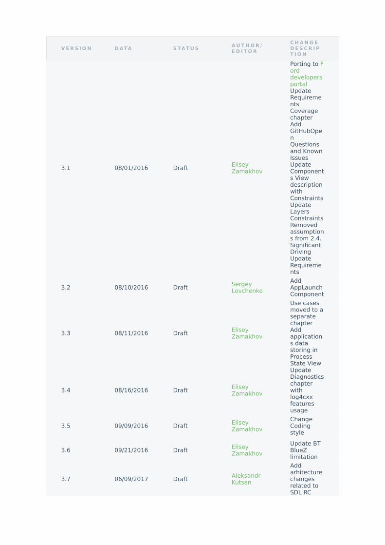
3.1 08/01/2016 Draft EliseyZamakhov
Porting to Forddevelopersportal UpdateRequirementsCoveragechapter AddGitHubOpenQuestionsand KnownIssues UpdateComponents ViewdescriptionwithConstraintsUpdateLayersConstraintsRemovedassumptions from 2.4.SignificantDriving UpdateRequirements
3.2 08/10/2016 Draft SergeyLevchenko
AddAppLaunchComponent
3.3 08/11/2016 Draft EliseyZamakhov
Use casesmoved to aseparatechapter Addapplications datastoring inProcessState View
3.4 08/16/2016 Draft EliseyZamakhov
UpdateDiagnosticschapterwithlog4cxxfeaturesusage
3.5 09/09/2016 Draft EliseyZamakhov
ChangeCodingstyle
3.6 09/21/2016 Draft EliseyZamakhov
Update BTBlueZlimitation
3.7 06/09/2017 Draft AleksandrKutsan
Addarhitecturechangesrelated toSDL RC

V E R S I O N D ATA A P P R O V E RA P P R O V EI T E M
There are several different types of configurations for SDL that you'll have to
understand in order for SDL to work properly and with the features you want on
your embedded platform.
cmake
You'll use the cmake configuration to set up SDL before you compile, and
enable or disable features like logging. The cmake file is located at sdl_core/
CMakeLists.txt.
smartDeviceLink.ini
The ini file located at build/src/appMain/smartDeviceLink.ini after you compile
and install SDL is your main configuration file for runtime configurations.
10.2. APPROVE HISTORY
2.2 06/11/2013 Julius Marchwicki -
2.2 06/11/2013 Pavel Savyelyev APPLINK-3967
3.0 06/30/2016 Nataly Snitsar APPLINK-25883
3.0 08/01/2016 Justin Dickow PR #4

sdl_preloaded_pt.json
The policy table located in build/src/appMain/sdl_preloaded_pt.json after you
compile and install SDL is the default policy table which provides the
permissions and default configurations for SDL on its first run before it receives
an update from a policy server.
The preloaded policy table located at src/appMain can be configured before
your first run of SDL to set permissions levels and urls.
Let's take a look at the values that can be configured.
N O T E
If you don't have a policy server and want to experiment with
changes in the policy table, you can either edit the policy database
directly with sqlite3 or edit the sdl_preloaded_pt.json, remove the
build/src/appMain/storage folder, and restart SDL to load the new
configuration.
N O T E
To configure SDL using the preloaded policy table after your first
run, remove the storage/ folder from build/src/appMain

Module Config
The module config section contains some global defaults that can be set for
SDL
Exchange After X Ignition Cycles
An "Exchange" is when SDL sends a request to a connected application to
retrieve a new policy table from the server. This value is the number of ignition
cycles before SDL initiates an exchange.
Exchange After X Kilometers
The distance traveled in the vehicle before SDL initiates an exchange
Exchange After X Days
The number of days that has passed before SDL initiated an exchange
Timeout After X Seconds
The amount of time SDL will wait for an exchange to complete before timing
out and retrying
Seconds Between Retries
A list of times in seconds to wait after a failed policy table exchange before
trying again. The number of items in this list determines the number of policy
table retries.

Endpoints
This section is a list of urls that is used throughout SDL
A list of urls that can be used for policy table exchanges
A list of urls that can be used to retrieve software updates
A list of urls that can be used to receive valid apps for querying on iOS devices
A list of urls that host an image which can be displayed by the application on
the driver's device during lockout. This url is sent in a request after each
application is registered. The application proxy downloads the image and sends
a notification to the application with the image to be displayed during lockout.
0X07
0X04
QUERYAPPSURL
LOCK_SCREEN_ICON_URL

Functional Groupings
The functional groupings are the different named groups of rpc permissions
that an application can have. There can be any number of functional groups.
The functional groups are used in the next section to define behavior for
different applications.
App Policies
The app policies are permissions that each application has on the system. This
is where you would change the default permissions for an application, or add
policies for a specific application.

SmartDeviceLink
Release Notes (Release 4.2.0)
1. Introduction
Definitions and Abbreviations
T E R M D E S C R I P T I O N
Scope
App Launch (iOS):
Integration of functionality already implemented in F-S SDL. Within the scope of
the CRQ integration, SDL team removeд iAP2 transport implementation and
Multiplexing functionality available in F-S SDL.
CY Calendar Year
CRQ Change request
SDL SmartDeviceLink
ATF Automated Test Framework
GitHub Source code revision system withreleased version of OpenSDL

New implementation of requested functionality:
• Navigation interface: SDL behavior in case HMI does not respond to
IsReady_request or respond with "available" = false• TTS interface: SDL behavior in case HMI does not respond to
IsReady_request or respond with "available" = false• UI interface: SDL behavior in case HMI does not respond to
IsReady_request or respond with "available" = false• VR interface: SDL behavior in case HMI does not respond to
IsReady_request or respond with "available" = false• VehicleInfo interface: SDL behavior in case HMI does not respond to
IsReady_request or respond with "available" = false
2 About This Release
Implemented functionality for remote launching the applications from the
supported Launch function devices.
Note: It is a business logic without supported device implementation.
For further details, please refer IAP, AOA, SDL Core SAD or your transport API
documentation.
Changed SDL behavior in case HMI does not respond to IsReady_request or
respond with "available" = false for following interfaces: VR, UI, TTS, Navigation
and VehicleInfo interfaces.
Short description of new behavior (INTERFACE is generic term used to
described any of VR, UI, TTS, Navigation and VehicleInfo interfaces):
1. HMI respond INTERFACE.IsReady (false) -> SDL must return
'UNSUPPORTED_RESOURCE, success:false' to all single INTERFACE-related
RPC2. HMI respond INTERFACE.IsReady (false) and app sends RPC that must be
splitted -> SDL must NOT transfer INTERFACE portion of splitted RPC to
HMI3. HMI does NOT respond to INTERFACE.IsReady_request -> SDL must
transfer received RPC to HMI even to non-responded INTERFACE module

3 Environment and dependencies
Development and testing environmentfor OpenSDL Ubuntu 14.04 LTS x32/x64
• Debug Environment: Ubuntu 14.04 LTS x32/x64, Qt 5.3• Compiler: GCC 4.9.3 (OS Ubuntu), Lua 5.2• Build system: Cmake 2.8.12.2
Development and testing environmentfor OpenSDL Windows x64:
• Build system: Windows 7 x64, CMake• Compiler: Microsoft Visual Studio Express Edition 2013 x64• Development and testing environment for OpenSDL Qt for Windows x32:• Build system: Windows 7 x32, Qt 5.5, CMake, QT Creator• Compiler: Microsoft Visual Studio Express Edition 2010 x32
Source Control System:
• GitHub

4. Delivery details
Unit Tests Coverage
C O V E R A G E H I T T O TA L C O V E R A G E
Tests Execution Report
T E S T ST O TA L
FA I LU R ES T O TA L
D I S A B LE DT O TA L
E R R O R ST O TA L
T O TA LT I M E( M I L L I SE C O N D S)
T E S T ST O TA L
Brief log of unit test sets execution:
01/26 Test #01: test_JSONCPP ...................... Passed 0.18 sec
02/26 Test #02: test_generated_interface .......... Passed 0.09 sec
03/26 Test #03: transport_manager_test ............ Passed 1.63 sec
04/26 Test #04: resumption_test ................... Passed 0.06 sec
05/26 Test #05: formatters_test ................... Passed 0.73 sec
06/26 Test #06: protocol_handler_test ............. Passed 22.37 sec
07/26 Test #07: connection_handler_test ........... Passed 83.31 sec
08/26 Test #08: utils_test ........................ Passed 36.30 sec
09/26 Test #09: generator_test .................... Passed 0.08 sec
10/26 Test #10: security_manager_test ............. Passed 10.28 sec
11/26 Test #11: policy_test ....................... Passed 108.36 sec
Lines 18153 27828 66 %
Functions 7646 11830 65 %
1748 0 16 0 310482 1748

12/26 Test #12: rpc_base_test ..................... Passed 0.18 sec
13/26 Test #13: smart_object_test ................. Passed 2.23 sec
14/26 Test #14: application_manager_test .......... Passed 3.00 sec
15/26 Test #15: resumption/data_resumption_test ... Passed 0.37 sec
16/26 Test #16: state_controller_test ............. Passed 0.37 sec
17/26 Test #17: app_launch_ctrl_test .............. Passed 43.12 sec
18/26 Test #18: app_launch_data_test .............. Passed 0.04 sec
19/26 Test #19: commands_test ..................... Passed 0.05 sec
20/26 Test #20: mobile_commands_test .............. Passed 0.19 sec
21/26 Test #21: hmi_commands_test ................. Passed 0.05 sec
22/26 Test #22: message_helper_test ............... Passed 0.01 sec
23/26 Test #23: hmi_message_handler_test .......... Passed 0.02 sec
24/26 Test #24: config_profile_test ............... Passed 0.33 sec
25/26 Test #25: media_manager_test ................ Passed 0.02 sec
26/26 Test #26: telemetry_monitor_test ............ Passed 0.02 sec
100% tests passed
5. Known Bugs and Limitations
All known SDL defects reflected in following chapter. The correction and
verification of those defects are out of scope of this release.

Known Issues

S U M M A RY P R I O R I T Y
[Genivi]SDL doesn't stop at executionATF function StopSDL() Blocker
[Genivi]: Core crash upon Ctrl+C inconsole Critical
[Genivi][Policies] PTU is not successfuldue to another unexpected exchange inprogress
Critical
[Genivi] SDL stops working duringprocessing SetGlobalProperties request Critical
[SDL4.0][Genivi] SDL sendsOnSystemRequest(QUERY_APPS) tobackground on phone App.
Critical
[Genivi] [TM] Unable to register iOS Appvia BT. Critical
[Genivi][Security] SDL do not sendcertificate from Policy DB and rewritescertificate in module_config with "1" rightafter using it
Critical
[Genivi][Security] SDL crashes if Apptries to restore secure RPC service onstart
Critical
[Genivi][Security] SDL crashes if duringTLS handshakeERROR_SSL_INVALID_DATA occurs
Critical
[Genivi][Security] SDL crashes if mobileApp fails TLS handshake. Critical
[GENIVI][WinQT] 3rd party USB librarycrash on exit Critical
[Resumption][Genivi] SDL crashes duringresumption of 2 Apps, non-media to FULLand media to LIMITED
Critical
[GENIVI] SDL should respond "IGNORED"with correct result code forUnSubscribeVehicleData in case viinterface isn't available
Critical
[GENIVI][Policy]: SDL does not sendRequestType:HTTP in OnSystemRequestto app
Critical
APPLINK-17839 Genivi: HMILevel is notresumed to LIMITED for non-mediaapplications
Major
APPLINK-17839 Genivi: HMILevelresumption is not canceled atOnEventChanged(AUDIO_SOURCE,isActive: true)
Major
[SDL4.0][Genivi] UTF-8: Core incorrecthandles symbols of two or more bytessize
Major

S U M M A RY P R I O R I T Y
[Genivi][Policies] SDL does not sendOnPermissionsChange after PTU Major
[Genivi][Policies] SDL doesn't excludemessages from snapshot Major
[GENIVI][Policy]: SDL dos not select urlfrom PT for specified appID duringGetURLs request.
Major
[Genivi] Policies Manager does not revertthe Local Policy Table to the PreloadPolicy Table upon FACTORY Reset
Major
[Genivi][Policies] SDL doesn't send"SDL.OnAppPermissionChanged{appID}to HMI
Major
[GENIVI][Security]: App continueunprotected stream if start service asprotected during active streaming
Major
[GENIVI][Memory leaks]: SDL does notrelease memory after sendingAddCommand limit exhausted
Major
[Genivi]: SDL send to mobile"APPLICATION_NOT_REGISTRED" insetAppIcon responce if HMI respond with"INVALID_DATA"
Major
[GENIVI] Incorrect response on sendSystemRequest (file name - /test) Major
[GENIVI] putFile does not copy file with .\before the name to AppStorageFolder Major
[GENIVI]SDL retry send StartStream/StartAudioStream less on one time thanconfigured in .ini file
Major
[Genivi][Policies] SDL doesn't reject PT ifthe consumer_friendly_message sectioncontains messaging without “en-us”language key
Major
[Genivi][Policies] PM should verify that"seconds_between_retries" array hasmaxlength 5
Major
[GENIVI] SDL transfer OnKeyboardInputnotification to not active App when thereis no active PerformInteraction(KEYBOARD)
Major
[Genivi] SDL forwards OnButtonPress(CUSTOM_BUTTON) with wrong appID tocurrent App.
Major
[Genivi] SDL forwards OnButtonPressnotification of CUSTOM_BUTTON toBACKGROUND App.
Major
[Genivi] SDL forwards OnButtonEventnotification of CUSTOM_BUTTON toBACKGROUND App.
Major
GENIVI: SDL doesn't send "REJECTED"code to mobile app when activating appfrom HMI with activate Carplay/GAL.GE
Major

S U M M A RY P R I O R I T Y
GENIVI: App is disconnected due toHeartBeat timeout althought HeartBeatis sent.
Major
Genivi SDL blocks forever whenregistering mobile application with GeniviHMI (only)
Major
[Genivi] HMI level resumption is notpostponded at EmergencyEvent,isActive=true
Major
[Genivi] SDL doesn't apply sequenceSUSPEND -> OnSDLAwake -> SUSPEND -> IGN_OFF for saving resumption data.
Major
[Genivi][API]SDL sends UpdateDeviceListwith disconnected device in thedeviceList
Major
[Genivi]CreateInteractionChoiceSet: coresuccessfully creates choice set withduplicate vrCommands/menuNameinside it.
Major
[Genivi][SDL4.0]SDL sends appName invrSynonyms and ttsName in case oflower and upper bound values of paramsin json file
Major
[Genivi][API] App is not unregistered byreason =REQUEST_WHILE_IN_NONE_HMI_LEVEL
Major
[Genivi][API] SDL sendsOnAppInterfaceUnregistered(DRIVER_DISTRACTION_VIOLATION) toapp when receives OnExitApplication(DRIVER_DISTRACTION_VIOLATION) fromHMI
Major
[GENIVI] One and the SameCorrelation_ID is assigned by SDL TwoTimes
Major
[Genivi][SDL4.0]SDL does not sendOnSystemRequest to app on seconddevice
Major
Genivi: Policy table can't be loaded whenRPCs added in functional_group isgreater than 50.
Major
[GENIVI][Policy]: SDL does not writeUserFriendlyMessages to DB Major
GENIVI: PerformAudioThru - SDL does notsend "resultCode:RETRY, success:true" tomobile app when press "Retry" button
Major
[Genivi][Policy] PM doesn't validaterequired section/key in case it is invalidand SDL continue running
Major
In Genivi (SDL 4) we can have twomobile apps in FULL HMI level at thesame time
Major
[Genivi][Policies] Ford-specific keys arepresent in Genivi Policy DB -usage_and_error_counts
Major

S U M M A RY P R I O R I T Y
[Genivi][Policies] PM doesn't update"notifications_per_minute_by_priority" Major
[Genivi][Policies] OnSystemRequest: SDLdoes not re-send OnSystemRequestnotification to mobile app in case when itwas sent from HMI without appID
Major
Unable to build GENIVI SDL without logs Major
[Genivi] SDL do not apply nicknamesafter PTU Major
[Genivi] SDL do not disallow API ofrevoked App. Major
[Genivi] SDL creates redundantdevice_consent table in Policy DB Major
[Genivi][Protocol] App becomesunregistered if PutFile is sent from any oftwo sessions (protocols v.2 and v.3)
Major
[Genivi][Protocol] SDL respond ACK withprotocol version 4 for video and audioservices if send start service with 2 or 3protocol version
Major
[Genivi][Policies] SDL should be case-insensetive to "AppID" against listed inpolicies manager
Major
[Genivi][Security] SDL close connectionbefore UNSUPPORTED_VERSION responsefor RAI was sent.
Major
[Genivi][Policies] PT is considered asvalid with no items in "groups" sub-section from "default"
Major
[Genivi][TV] SDL must respond withINVALID_DATA on SystemRequest thatuploads a file containing ../ sequences
Major
[Genivi][IVSU] SDL doesn't rejectSystemRequest with filenam=IVSU butw/o binary data.
Major
[Genivi] Core dump uponFACTORY_DEFAULT Major
[Genivi][Policies] PM doesn't validate thesize of section "default" in "endponts" ofPolicy Table
Major
[Genivi][Policy]: PM doesn't merge"functional_grouping" and"message_type"
Major
[Genivi][APIs] AlertManeuver: SDLresponds GENERIC_ERROR instead ofINVALID_DATA when soft button has Typeis Image or Both and Text is whitespaceor \t or \n or empty
Major

S U M M A RY P R I O R I T Y
[Genivi][API]AlertManeuver:SDL respondsto mobile app UNSUPPORTED_REQUESTwith success = true
Major
[Genivi][SDL4.0] Json validation is failedin case language parameter does notcontain vrSynonyms or ttsName
Major
[Genivi][SDL4.0]SDL sendsOnSystemRequest(QUERY_APPS) to theapp after unsuccessful attempt
Major
[Genivi]SDL returns IGNORED instead ofUNSUPPORTED_RESOURCE forUnsubscribeButton.
Major
[Genivi]SDL do not send default vrHelpto HMI if App was registered withvrSynonyms
Major
[Genivi] [TM] SDL can't reregister App viaUSB that was killed before. Major
[Genivi] OnHashChange notification forUnsubscribeVehicleData when 2applications are registered
Major
GENIVI: SDL responds "resultCode:SUCCESS" whiledataType:VEHICLEDATA_EXTERNTEMP isVEHICLE_DATA_NOT_AVAILABLE and notin subscribed list store
Major
[GENIVI] No response to App on UI.Slidersent if no HMI response duringDefaultTimeout
Major
[GENIVI][Policy]: SDL does not set"timeout" for OnSystemRequest with url Major
[GENIVI][Policy]: SDL does not apply urlfrom PT for specified appID forOnSystemRequest
Major
[Genivi] INVALID_DATA received in casewayPointType with correct parameterwas sent
Major
[Genivi][API] SDL responds"UNSUPPORTED_RESOURCE", success=false in case only have"UNSUPPORTED_RESOURCE" toNavigation.AlertManeuver
Major
GENIVI: App is disconnected due toPROTOCOL_VIOLATION when start audiostreaming after rejected 2 times thenaccepted.
Major
[GENIVI]: SDL crashes during executionATF test with start-stop SDL cases Major
[GENIVI] Redundant info is sent to Appwhen single UI. got'UNSUPPORTED_RESOURCE' from HMI
Major
[Genivi] SDL responses withGENERIC_ERROR instead ofUNSUPPORTED_RESOURCE
Major

S U M M A RY P R I O R I T Y
[GENIVI] SDL does not transfer all infoparameters of unsuccess result codeswhen UI.IsReady = false
Major
[GENIVI] SDL does not respond infomessage in case GENERIC_ERRORwatchdog timeout from HM
Major
GENIVI: SDL does not sendVehicleInfo.GetVehicleData in case HMIresponds invalid json for TTS.IsReady andtrue for VehicleInfo.IsReady
Major
[GENIVI][Navigation] SDL does notrespond info message in caseGENERIC_ERROR watchdog timeout fromHM
Major
[GENIVI] GetWayPoints: SDL does notreset the default watchdog timeout ofGetWayPoints request if HMI sendsOnResetTimeout notification for thisrequest
Major
[GENIVI] HashID should not be updatedon successful single UI. if no UI.IsReadyresponse
Major
[GENIVI] USER_DISALLOWED sendinstead of IGNORED forUnsubscribedVehicleData whenVehicleInfo IsReady Missing
Major
[GENIVI] SDL responds "WARNINGS" codein case SDL got "WARNINGS" from TTSand error code from other interfaces.
Major
[GENIVI] SDL doesn't set unsuccessful"message" value to "info" param in caseHMI responds via single UI.RPC when.IsReady missing
Major
[Policies][Genivi] PM shuts SDL down butdoesn't log error in case any requiredsection/key is absent in thesdl_prealoaded_pt.json
Normal
[Genivi] OpenSDL repo still contains old"generate_test_certificates.py" script. Normal
GENIVI: SDL does not sendStopAudioStream() if exit app while Videoservice and Audio service are starting.
Normal
[GENIVI]The session registration isdelayed by locks Normal
[Genivi][SDL4.0]SDL does not createicons folder in case it was removed afterSDL start
Normal
[Genivi][API] SDL sendsBC.UpdateDeviceList with out of upperbound size of deviceList
Normal
[Genivi][SDL4.0] SDL sends wrongparameter names in OnSystemRequest(query_apps)
Normal
[GENIVI][Policy]: SDL increments"ignition_cycles_since_last_exchange"counter after ign cycle if PTU was notbefore
Normal

S U M M A RY P R I O R I T Y
[SDL4.0][Genivi] incorrect resp. in caseUnsubscribe not supported and not yetsubscribed button
Normal
[Genivi][Policies] Ford-specific keys arepresent in Genivi Policy DB - DeviceData Normal
[Genivi][Policies]: "application" tablecontains "certificate" Normal
[Genivi] SDL doesn't add device identifierto Policy DB and not present in thesnapshot
Normal
[Genivi][Security] SDL print out CN andserialNumber details of certificates inlog.
Normal
[Genivi][VS][AS] SDL does not sendStopStream/StopAudioStream to HMIafter unregistering app during streaming
Normal
[Genivi] Communication is not saved inSmartDeviceLinkCore.log after addingpersistent data after SUSPEND
Normal
[Genivi]SDL doesn't transfer infoparameter with UI.SetGlobalProperties tomobile.
Normal
[Genivi]SDL sendssystemSoftwareVersion (with emptyvalue) in RAI response if beforeccpu_version was invalid inGetSystemInfo.
Normal
[Genivi][Policies] Policy table is notinitialized by SDL start without DB Normal
[GENIVI] Response toUI.ScrollableMessage is sent twice to appif no HMI response HMI during
Normal
[Genivi]SDL doesn't send info parameterwhen result of ResetGlobalProperties isGENERIC_ERROR
Normal
Genivi: UI is waiting for TTS.IsReadytimeout to elapse to send UI. Normal
[Genivi] SDL response success:false tomobile app in case it received RETRY orWRONG_LANGUAGE orUNSUPPORTED_RESOURCE from HMI
Normal
GENIVI: SDL always reponds"INVALID_DATA" to mobile app whilereceiving other code from HMI
Normal
[Genivi] Incorrect Version of API inMOBILE_API.xml Normal
[GENIVI] SDL build without any errormessage with empty version inMOBILE_API.xml
Minor

S U M M A RY P R I O R I T Y
SDL Core 4.3.0 Release Notes
New Features
EXTENDED_POLICY modes:
• The EXTENDED_POLICY CMake variable (previously
ENABLE_EXTENDED_POLICY) now has three possible configurations
◦ HTTP (previously ENABLE_EXTENDED_POLICY: OFF) - Details ◦ PROPRIETARY (previously ENABLE_EXTENDED_POLICY: ON) - Details◦ EXTERNAL_PROPRIETARY (new, fully featured version of
PROPRIETARY mode) - Details
EXTERNAL_PROPRIETARY mode:
A new policy table update flow was created specifically for the
EXTERNAL_PROPRIETARY policy mode
• Requirements/Details • Diagram
[GENIVI] SyncMsgVersion is not updatedafter RegisterAppInterface Minor
NEW POLICY TABLE UPDATE SEQUENCE

As part of the EXTERNAL_PROPRIETARY policy mode, the concept of an
"external policy manager" is necessary. This policy manager is a separate
program which is in charge of encrypting/decrypting policy tables and attaching
an HTTP header to the OnSystemRequest payload when performing a Policy
Table Update.
As part of this release, a sample application which performs this function was
added to this repository for those who wish to implement this new policy mode,
and this program can be started along with Core using an included bash script.
This sample application does nothing with the policy table snapshot during the
encryption and decryption phases, allowing for OEMs to implement their own
encryption algorithms in their place.
Users can now control what functional groups that they want apps to be able to
access, as well as decide whether to enable SDL functionality at all on a device-
by-device basis.
• Logic was added to allow the user to control what devices are permitted to
use SDL functionality - Details
◦ Users are prompted when activating an app on a new device for the
first time whether or not to allow the device to use SDL functionality
(sequence shown in this diagram)
• Logic was added to the Policy Manager to allow the user to control what
apps have access to specific functional groups - Details
◦ Users are prompted when activating an app for the first time (or
modifying permissions in settings) with information on what access a
EXTERNAL POLICY MANAGER
APP PERMISSIONS/USER CONSENT

requested functional group requires. The user responds to determine
whether or not to allow this functionality within the new app
(sequence shown in this diagram)
External user consent allows the HMI to define several groups of permissions
within the policy table. This allows the user to enable/disable several functional
groups at once.
• The externalConsentStatus field is included as part of a
GetListOfPermissions response from SDL Core to communicate which
groups are activated - Details• External consent groups can be used to enable sets of functional groups
using the disallowed_by_external_consent_entities_off field in the Policy
Table - Details
◦ If this external consent group is set to ON, all functional groupings
with this parameter are allowed by the user - Details◦ If this external consent group is set to OFF, all functional groupings
with this parameter are disallowed by the user - Details
• External consent groups can be used to disable sets of functional groups
using the disallowed_by_external_consent_entities_on field in the Policy
Table
◦ If this external consent group is set to ON, all functional groupings
with this parameter are disallowed by the user
EXTERNAL USER CONSENT

◦ If this external consent group is set to OFF, all functional groupings
with this parameter are allowed by the user
Prior to this release, several functions included in cache_manager.cc were not
fully implemented and would not query the local policy table for defined rules
and policies. The newly implemented functions for the
EXTERNAL_PROPRIETARY cache manager are listed below:
• CanAppKeepContext()• CanAppStealFocus()• GetDefaultHMI()• ResetUserConsent()• GetUserPermissionsForDevice()• GetPreconsentedGroups()• GetConsentedGroups()• GetUnconsentedGroups()• RemoveAppConsentForGroup()• GetDeviceGroupsFromPolicies()• SetDeviceData()• SetUserPermissionsForDevice()• ReactOnUserDevConsentForApp()• SetUserPermissionsForApp()• CountUnconsentedGroups()• SetMetaInfo() • IsMetaInfoPresent()• SetSystemLanguage()• CleanupUnpairedDevices()• SetVinValue()
CACHE MANAGER FUNCTION IMPLEMENTATIONS

• ResetPT()
Requirements/Details
HMI_API additions:
A new RPC was added as part of the implementation of
EXTERNAL_PROPRIETARY policy mode
• DecryptCertificate RPC
Several API additions were made as part of the implementation of the external
user consent feature
• EntityStatus enum• ExternalConsentStatus struct• externalConsentStatus field added to OnAppPermissionConsent and
GetListOfPermissions
Implemented proposals
Two new evolution proposals were implemented in release 4.3.0:
• Add API Patch Version SDL-0050• A patch version was added to the MOBILE API version, HMI API interface
versions, and SyncMsgVersion struct• External Policy Manager SDL-0045• Details for the implementation of this proposal can be found in the
External Policy Manager section of these release notes
SECURITY BEHAVIOR

Fixes
• Includes fixes for all defects found by the Coverity scan tool that were
introduced in this release - Link• Includes fixes for several Coverity defects that were previously
implemented in the coverity branch - Link
SDL Core 4.3.1 Release Notes
Bug Fixes
• ListFiles request now queries the file system on each request instead of
referring to a cached list - Link
SDL Core 4.4.0 Release Notes
Implemented Proposals
System Capabilities Query - Implementation of a new RPC which allows an app
to query the capabilities of a specific component (i.e. video streaming, remote
control) within a given integration of SDL Core.
Constructed Payloads - Addition of constructed payloads for control (non-RPC
type) packets. These payloads allow for control packets to be more descriptive
without using the overhead needed by an RPC message. The feature has been

implemented using the BSON standard through use of the bson_c_lib. This
includes the introduction of protocol version 5, versions prior to this do not
support this feature.
Control Frame Payloads v1.0.0 - Introduced specific parameters that will be sent
with a control frame's constructed payload. This is part of the introduction of
protocol version 5, versions prior to this do not support this feature.
Support Indian English and Thai - Adds the possibility to support languages
English - India and Thai - Thailand .
Support For Additional Languages - Adds the possibility to support 8 new
languages.
Mobile Projection - Defines new AppHMIType PROJECTION . This AppHMIType
allows an app to use the same video streaming technologies as a navigation
app.
Gesture Cancellation - Addition of a CANCEL element to the TouchType Enum
used during an OnTouchEvent RPC.
Add Video Streaming Capabilities - Allows core to notify the proxy of the HMI's
video streaming capabilities. This addition also includes a video format
negotiation procedure that uses a combination of RPC and constructed payload
messages.
Adding Metadata Types - Add metadataTags parameter to the Show RPC, as
well as the new types MetadataTag and MetadataType . These additions allow
for a more detailed description of the main field strings sent during a Show RPC
request.
Human Interface Device Support - Implementation of the SendHapticData
RPC. This RPC sends the HMI an array of rectangle coordinates for focusable
elements used during video streaming.
Remote Control Baseline - Implementation of a new core plugin/functional
module RemoteControl . This feature includes a set of RPCs that the proxy may
use to control certain aspects of the HMI's climate and radio modules. Changes
also include additions to the GetSystemCapability RPC and policy
configurations.

Update Mobile API Mandatory Flag - Update formatting of MOBILE_API.xml to
include the mandatory flag on all parameters.
Bug Fixes
Video Streaming Related
• Core still sends out deprecated Service Data ACK frames• Proper Cleanup for the StreamerAdapter class• SDL does not send StopStream/StopAudioStream to HMI after
unregistering app during streaming
Connection Related
• TransportManager that incorrectly deletes a connection object within a C+
+ map iterator loop• Core cannot find App via BT • Connection List Lock is Not Released• Invalid memory access in websocket_handler
Policy Related
• SDL does not set "timeout" for OnSystemRequest with url• Policies Manager does not revert the Local Policy Table to the Preload
Policy Table upon FACTORY Rese• SDL does not write UserFriendlyMessages to DB• SDL dos not select url from PT for specified appID during GetURLs request.• PM should verify that "seconds_between_retries" array has maxlength 5• SDL does not apply url from PT for specified appID for OnSystemRequest• PM doesn't validate the size of section "default" in "endpoints" of Policy
Table• Policy table can't be loaded when RPCs added in functional_group is
greater than 50.

• PT is considered as valid with no items in "groups" sub-section from
"default"
Documentation
• README should not reference "v4tester" application• Create an Issue template for sdl_core
General Fixes
• media_manager_test fails with EXTENDED_MEDIA_MODE=ON• Memory leak in FromMicToFileRecorderThread• Invalid memory access in FromMicToFileRecorderThread• SDL does not reset the default watchdog timeout of GetWayPoints request
if HMI sends OnResetTimeout notification for this request• SDL sends BC.UpdateDeviceList with out of upper bound size of deviceList• HashID should not be updated on successful single UI. if no UI.IsReady
response• OpenSDL repo still contains old "generate_test_certificates.py" script.• SDL does not send VehicleInfo.GetVehicleData in case HMI responds
invalid json• SDL print out CN and serialNumber details of certificates in log.• SDL returns IGNORED instead of UNSUPPORTED_RESOURCE for
UnsubscribeButton• SDL must respond with INVALID_DATA on SystemRequest that uploads a
file containing "../" sequences
SDL Core 4.4.1 Release Notes
Bug Fixes
• Remote Control Applications Auto Activate Apps

• MaxSupportedProtocolVersion is in the wrong section of the INI
ATF Software Architecture Document(SAD)
Table of contents
• 1. Introduction
◦ 1.1. Purpose and Scope of the SAD◦ 1.2. Definitions and Abbreviations◦ 1.3. Document Roadmap
• 2. Case Background
◦ 2.1. System Context, Mission and Scope◦ 2.2. Product Stakeholders◦ 2.3. Business Goals◦ 2.4. Significant Driving Requirements
• 3. Solution Overview• 4. Views
◦ 4.1. Use Case View◦ 4.2. Components View◦ 4.3. Component Interaction View
▪ 4.3.1. User Scripts Execution with ATF▪ 4.3.2. User Script loading▪ 4.3.3. User Function execution▪ 4.3.4. Events and expectations processing
◦ 4.4. User Interface◦ 4.5. Data View◦ 4.6. Process State View◦ 4.7. Process View
◦ 4.8. Development View
▪ 4.8.1. Implementation Technologies▪ 4.8.2. Modules and Code Base Organization▪ 4.8.3. Development Environment and Standards
◦ 4.9. Deployment View◦ 4.10. Operational View
• 5. View-to-View Relations
◦ 5.1. Component-to-Layer◦ 5.2. Data-to-Layer View
• 6. Solution Background
◦ 6.1. Architecture Design Approach◦ 6.2. Requirements Coverage◦ 6.3. Prototyping Results◦ 6.4. Open Questions and Known Issues◦ 6.5. Results Analysis
• 7. References• 8. List of Figures• 9. Appendices• 10. History
1. Introduction
1.1. Purpose and Scope of the SAD
This document defines the high-level software architecture for the Automated
Test Framework (ATF) system. It describes the structure and the main
components of the system, the project basis and dependencies. The goal of the
document is to describe, in sufficient detail, the software components, their
responsibilities, behavior, and interfaces. This document provides support for

Luxoft, Ford, open-source developers and others to learn system design,
limitations, stakeholders, and ways of extension and further development.
1.2. Definitions and Abbreviations
Abbreviations used in this document please find in the table below.
A B B R E V I AT I O N E X PA N S I O N
Definitions used in this document are in the table below.
D E F I N I T I O N D E S C R I P T I O N
For further definitions and abbreviations, please follow SDL SAD
1.3. Document Roadmap
The SW architecture of system is considered from different viewpoints:
SDL SmartDeviceLink
Concern A functional or non-functionalrequirement.
Model
A particular diagram or descriptionconstructed following the methoddefined in a viewpoint. These provide thespecific description of the system, whichcan include identifiable subsystems andelements.
StakeholderAn individual, group or organization thathas at least one concern relating to thesystem.

V I E W P O I N T V I E W P O I N T D E S C R I P T I O N
ComponentFunctional type of view which describesthe system's runtime functional elementsand their responsibilities.
Component Interaction
Functional type of view which describesinteractions of the system's functionalelements. Component Interaction viewuses component-level sequence orcollaboration diagrams to show howspecific components will interact. Thepurpose is to validate structural designvia exploration of the software dynamics.
Use Case
Use Case View captures systemfunctionality as it is seen by users.System behavior, that is whatfunctionality it must provide, isdocumented in a use case model.
User InterfaceFunctional type of view which describesinterfaces of the system's functionalelements.
Data
Describes the way that the systemstores, manipulates, manages, anddistributes information. The ultimatepurpose of virtually any computersystem is to manipulate information insome form, and this viewpoint developsa complete but high-level view of staticdata structure and information flow. Theobjective of this analysis is to answer thequestions around data content, structure,ownership, quality, consistency updatelatency, references, volumes, aging,retention, and migration.
Process State
Concurrency type of view. Process StateView is used to model standard processdynamics that are independent of theloaded components. These dynamicsmay, for example, be part of acomponent management infrastructurethat loads and controls components inthe process. For process dynamics, it isoften useful to think in terms of astandard set of states such as initializing,operating, and shutting down
Process
Concurrency type of view. Process Viewdescribes processes and process inter-communication mechanismsindependent of physical hardwaredeployment
Development
Describes the architecture that supportsthe software development Process. Thisview addresses the specific concerns ofthe software developers and testers,namely code structure anddependencies, build and configurationmanagement of deliverables, designconstraints and patterns, and namingstandards, etc. The importance of thisview depends on the complexity of thesystem being built, whether it isconfiguring and scripting off-the-shelfsoftware, writing a system from scratch,or something between these extremes.

V I E W P O I N T V I E W P O I N T D E S C R I P T I O N
For more information about Viewpoints refer to Architectural Blueprints The “4
+1” View Model of Software Architecture:
- http://www.cs.ubc.ca/~gregor/teaching/papers/4+1view-architecture.pdf
For detailed UML diagrams notation description please refer to :
- http://www.uml-diagrams.org/
- https://sourcemaking.com/uml
2. Case Background
2.1. System Context, Mission and Scope
ATF is a C++/Lua framework for SDL automated black-box testing.
It provides high- and low-level API for mobile applications and/or HMIs
emulation.
ATF core lua-scripts provides API for SDL easy manipulation:
- Start and stop SDL
Deployment
Describes the environment into whichthe system will be deployed and thedependencies that the system has onelements of it. This view captures thehardware environment that your systemneeds (primarily the processing nodes,network interconnections, and diskstorage facilities required), the technicalenvironment requirements for eachelement, and the mapping of thesoftware elements to the runtimeenvironment that will execute them.
Operational
Describes how the system will beoperated, administered, and supportedwhen it is running in its productionenvironment. The aim is to identifysystem-wide strategies for addressingthe operational concerns of the system'sstakeholders and to identify solutionsthat address these
Logical
Logical view focuses on the functionalneeds of the system, emphasizing on theservices that the system provides to theusers. It is a set of conceptual models.

- Emulation websocket HMI, HMI interfaces registration and subscription
- Emulation TCP mobile connection and FORD protocol session establishing
- Expectation HMI and mobile RPC from SDL
- Expectation extensions with setting up timeouts, call-chains and fields
validation
- SDL messages auto-validation
2.2. Product Stakeholders
Actors are stakeholders that interact with product directly.
S TA K E H O L D E R N A M E A C T O R ( Y E S / N O ) C O N C E R N
2.3. Business Goals
ATF system allows to automatize SDL regression testing and decreasing
functional end regression costs.
ATF with a smoke tests scripts suite provide Continuous testing and Continuous
delivery for SDL open-source developers and integrators.
2.4. Significant Driving Requirements
The requirements are listed in the table below and ordered by descending of
their significance from architectural solution point of view.
Ford Company No
Get the ATF system withenough quality andfunctionality that fulfilltheir goals
SDL Automation Testteams Yes
Get the ATF system withenough functionality forSDL testing coverage
PM / Architect / Analyst NoUse CustomerRequirementsSpecification
Developers NoConstruct and deploythe system fromspecifications
ATF Test team NoTest the system toensure that it is suitablefor use

#D R I V I N G R E Q U I R E M E N TD E S C R I P T I O N
3. Solution Overview
The picture below shows ATF overview.
SEQUENCE DIAGRAM
1.ATF has to be POSIX-compliant to beeasily ported on all POSIX standardizedOSs.
2. Script language need to be used as amain-tool for simplification.
3. ATF shall provide a High-level API for SDLmanipulation.
SOLUTION OVERVIEW
View Diagram

4. Views
4.1. Use Case View
The following Use Case diagrams show the actors, the processes and their
interactions within SDL System.
SEQUENCE DIAGRAM
SEQUENCE DIAGRAM
TEST DOMAIN OVERVIEW USE CASE DIAGRAM
AUTOMATION TEST ACTIVIT IES USE CASE DIAGRAM
View Diagram
View Diagram

SEQUENCE DIAGRAM
TEST SCRIPT EXECUTION USE CASE DIAGRAM
View Diagram

SEQUENCE DIAGRAM
SDL MANIPULATION USE CASE DIAGRAM
View Diagram

SEQUENCE DIAGRAM
MOBILE EMULATION USE CASE DIAGRAM
View Diagram

SEQUENCE DIAGRAM
4.2. Components View
The view is represented by module and subsystem diagrams that show the
system's export and import relationships. The Components View diagram and
its elements description please see below.
SEQUENCE DIAGRAM
C O M P O N E N T V I E W D I AG RA M
HMI EMULATION USE CASE DIAGRAM
View Diagram

Elements description
• Responsibility:
◦ Contains automated test cases written by User
• Relations
◦ Composes Connection Test
• Interfaces
◦ Does not provide any external interfaces
• Behavior
◦ User Script implements SDL Tests by using ATF API.
• Constraints
◦ User scripts are not part of ATF delivering.
USER SCRIPT
View Diagram

Application layer:
• Responsibility
◦ Declares a command line arguments◦ Starts User Scripts list one by one
• Relations
◦ Starts User Scripts
• Interfaces
◦ Does not provide any external interfaces
• Behavior
◦ Launch declares command line arguments and execute all left
parameters as User Scripts
• Constraints
◦ Needs to be run by C++ Core◦ Note: ATF provides run_tests.sh script for automation run Launch by
C++ Core
• Responsibility
◦ Provides testing API:◦ Start and Stop SDL◦ Activation and Deactivation HMI◦ Starting mobile connection and session◦ Set up HMI and Mobile RPCs expectations◦ Composes all lower level components
LAUNCH
CONNECTION TEST

• Relations
◦ Used by User Script for SDL manipulation
• Interfaces
◦ Provides Test interface for User Script
• Behavior
◦ Connection Test works as a Facade for accumulation all ATF
Functionality and providing Expectation wrappers for RPCs.
• Constraints
◦ N/A
Data assess layer:
• Responsibility
Provides configuration for:
◦ setting up ATF behavior◦ SDL manipulation parameters◦ Emulating applications parameters
• Relations
◦ Used by all components◦ Is filled by Utils
• Interfaces
◦ Provides Config interface
• Behavior
◦ Contains a list of defined parameters for reading and modification.
CONFIG

• Constraints
◦ N/A
• Responsibility
◦ Global events and expectations subscription with a timeout◦ Global event notification
• Relations
◦ Used by all components.
• Interfaces
◦ Provides Events interface
• Behavior
◦ Provides centralized mechanism for components synchronization and
expectation subscription
• Constraints
◦ N/A
• Responsibility
◦ Logging ATF internal information◦ Providing XML reports of ATF scripts execution results
• Relations
◦ Used by all components.
EVENTS
ATF LOGGER

• Interfaces
◦ Provides ATF logger interface
• Behavior
◦ ATF logger provides API for logging all internal information for
further SDL issues analysis
• Constraints
◦ N/A
• Responsibility
◦ Support methods implementation◦ Encapsulation system API calls◦ Parsing command line arguments
• Relations
◦ Used by all components.
• Interfaces
◦ Provides Utils interface
• Behavior
◦ Utils is wrapper for stdlib library and C++ Core methods
UTILS

• Constraints
◦ N/A
• Responsibility
◦ Providing additional Utility object, which could not be implemented
with Native Lua API or stdlib:◦ timer◦ Qt signal/slot system ◦ XML parsing◦ Web-Sockets◦ Tcp-Sockets
• Relations
◦ Requires Qt Framework for signal/slots system, WebSocket
implementation◦ Requires Lua Development Library Kit
• Interfaces
◦ Provides set of Lua interfaces
• Behavior
◦ C++ Core wraps Qt and Posix API for Utils◦ Provides executable for starting Lua scripts with additional Qt meta-
system functionality.◦ C++ Core executable parses with Launch as a first argument, all
following parameters are passed to the Launch.
• Constraints
◦ Requires Qt 5.3+ for WebSocket support
C++ CORE

◦ Requires Lua Development kit version 5.2
Business layer:
• Responsibility
◦ Starts and stops SDL executable manipulation◦ SDL executable status monitoring◦ SDL log grabbing via telnet and save it to corresponding directory.
• Relations
◦ Requires Data assess layer interfaces
• Interfaces
◦ Provides SDL interface
• Behavior
◦ Starts SDL binary and saves process id for further stop and status
monitoring.
• Constraints
◦ Requires POSIX system environment for bash script and calling OS
commands like cat, test, cat, sleep
• Responsibility
◦ Test cases consecutive execution◦ Each test case verification check:◦ User Script expectation◦ SDL executable status monitoring
SDL
TEST BASE

• Relations
◦ Requires SDL interface◦ Requires Events interface
• Interfaces
◦ Provides Test Base interface
• Behavior
◦ User Script test cases are executing one by one with verifying all
expectation.
• Constraints
◦ N/A
• Responsibility
◦ RPCs structure and format validation
• Relations
◦ Requires Data assess layer interfaces
• Interfaces
◦ Provides Validator interface
• Behavior
◦ Dynamically loads HMI_API.xml and MOBILE_API.xml API for further
validation income RPCs from SDL.
VALIDATOR

• Constraints
◦ Requires HMI_API.xml and MOBILE_API.xml files
Protocol layer:
• Responsibility
◦ Control and business data distributing to appropriate sessions and
service◦ Control messages processing◦ Multi-frames assembling and disassembling
• Relations
◦ Requires Data assess layer interfaces
• Interfaces
◦ Provides Protocol Handler interface
• Behavior
◦ Decodes income raw transport data and encodes outcome RPCs
according to protocol specification.
• Constraints
◦ SmartDeviceLink Protocol specification
• Responsibility
◦ Sessions and services manipulation◦ Sending data to mobile services◦ Subscription to income mobile service data
PROTOCOL HANDLER
MOBILE SESSION

◦ Heartbeat functionality
• Relations
◦ Requires Data assess layer interfaces
• Interfaces
◦ Provides Mobile Session interface
• Behavior
◦ Accumulates API for session and services managing
• Constraints
◦ SmartDeviceLink Protocol specification
Transport layer:
• Responsibility
◦ Establish HMI connection to SDL◦ Sending HMI-related data◦ Subscription to income HMI data
• Relations
◦ Requires Data assess layer interfaces
• Interfaces
◦ Provides HMI connection interface
• Behavior
◦ Wraps WebSocket connection to SDL
• Constraints
◦ WebSocket API provided by Qt throw *Utils
HMI CONNECTION

• Responsibility
◦ Establish Mobile connection to SDL◦ Sending Mobile related data◦ Subscription to income Mobile data◦ Outcome data caching to file before sending to SDL
• Relations
◦ Requires Data assess layer interfaces
• Interfaces
◦ Provides Mobile connection interface
• Behavior
◦ Wraps TCP connection to SDL and provides caching to file
abstraction, which prevent ATF memory overflow
• Constraints
◦ TCP API provided by Qt throw Utils
4.3. Component Interaction View
4.3.1. User Scripts Execution with ATF
Behavior:
User starts C++ Core with a list of command line arguments.
C++ Core executable launches Lua interpreter, which executes first command
line argument as a script with the rest of parameters.
In case of passing Launch as a first parameter Launch parse configurable
parameters and consecutively load User scripts.
MOBILE CONNECTION

After Loading all User Scripts* C++ Core** execute Qt Meta-Object System,
which starts Timers and Events processing.
SEQUENCE DIAGRAM
User Scripts Execution with ATF
View Diagram

4.3.2. User Script loading
Behavior:
User Script loads Connection Test as a testing and SDL manipulation API
provider.
Connection Test loads components of Transport, Protocol and Business layers.
User Script loads Function from own source code.
In case of loading Function with a first letter in upper case Test Base module

interpreter it as a Test for further consecutive execution. All other User Script
Functions are loaded in a common way and used as a support for Test
functions.
SEQUENCE DIAGRAM
User Script loading diagram
4.3.3. User Function execution
Behavior:
After loading User Script and ATF modules, Test Base starts consecutive list
of User Functions execution.
Each Functions has ability to manipulate SDL, HMI and Mobile connections with
Connection Test API.
View Diagram

Note: Some Tests do not require all options due to emulation SDL exception
cases.
For preparing consecutive test scenarios User Script able to emulate HMI,
Mobile RPC and set SDL-result expectations.
SEQUENCE DIAGRAM
User Function execution diagram
View Diagram

4.3.4. Events and expectations processing
Behavior:
Events and expectation processing procedure could be spited up for :
Setting up expectation - User Script throw the Connection Test able to add
some expectations for event and add timer for the event fail processing.
Events processing - On raising specific event Events is responsible for calling
exception Function, on time elapse C++ Core directly call User or other
modules Function.
SEQUENCE DIAGRAM
Events and expectations processing diagram
View Diagram

4.4. User Interface
Not applicable, since the User Interface is not the part of development.

4.5. Data View
The Data View shows relations between separated data types and actors that
perform information processing in the system. It depicts contents of saved
information and also visualizes information sources, processors and destination.
The following Diagram shows relations between separated data types and
actors that perform information processing in the SmartDeviceLink.
SEQUENCE DIAGRAM
DATA F LO W D I AG RA M
View Diagram

Elements description
All following type are lua tables due to language specifics.
For further information about lua tables type refer to Lua Tables Tutorial
• Summary:
◦ Binary data stream from Mobile socket connection
• Usage:
◦ Income and outcome data for Transport layer to OS or 3d-party
library
• Summary:
◦ Binary data stream from HMI WebSocket connection
GENERAL NOTE:
SOCKET RAW DATA
WEBSOCKET RAW DATA

• Usage:
◦ Income and outcome data for Transport layer to OS or 3d-party
library
• Summary:
◦ Protocol layer primitive with protocol related information
• Usage:
◦ Internally by Protocol layer for protocol header information
prepossessing
• Summary:
◦ Data for sending to Mobile side.◦ Used for avoiding flooding SDL by ATF
• Usage:
◦ Internally by Transport layer for Mobile-to-SDL messages
• Summary:
◦ String data of serialized RPC in Json format
• Usage:
◦ Internally by Business layer as a middle state between hi-level RPC
abstractions and transport/protocol layers
FORD PROTOCOL PACKET
CACHED DATA
JSON DATA

• Summary:
◦ RPCs primitive types with all related fields and parameters
• Usage:
◦ Internally by Business layer as for RPCs validation◦ By User scripts for request-response logic implementation
4.6. Process State View
The process State view shows the global ATF states according to system life
cycle.
ATF states are related to User Script implementation and usually includes ATF
waiting HMI and Mobile connections.
Following diagrams is focused on ATF Core component and shows to the User
Script events processing.
SEQUENCE DIAGRAM
L I F E CYC L E S TAT E S D I AG RA M
HMI AND MOBILE RPC
View Diagram

Elements description
• Behaviour:
◦ ATF initialize own components and load User Scripts
• Relations:
◦ If all ATF subsystems and User Scripts successfully loaded, ATF starts
processing Test Cases.◦ If failed, ATF is shutting down.
• Behaviour:
◦ ATF executes User Scripts test cases: emulates Mobile, HMI side,
add and verifies expectations
INIT IALIZATION
TESTING

◦ ATF handles Events, proceeds according to own business
requirements and provides to User Script verification.
• Relations:
◦ ATF starts shutdown procedure on getting stop signal and in case of
Critical Test Case failure.
• Behaviour:
◦ ATF stores all disconnects from SDL and deinitializes all components.
• Relations:
◦ Finish ATF life cycle
4.7. Process View
Not applicable, since the developed system works within one process.
4.8. Development View
4.8.1. Implementation Technologies
• C++11 language is selected as a programming language for ATF Core
binary as a OS and CPU architecture independent.• Qt selected as a cross-platform Framework for ATF utility support: Signal-
Slot metasystem, Websocket implementation, timers and so on• Note: Version Qt 5.3 is required for WebScoket transport support.
SHUTTING DOWN

• Lua language selected as a lightweight, embeddable scripting language
for ATF Components and *User Scripts implementation
4.8.2. Modules and Code Base Organization
Development view organizes ATF components into a separate directories:
• src - C++ source code for ATF C++ Core.• modules - Lua components• modules/protocol_handler - Protocol handler components• modules/atf - Utility components
4.8.3. Development Environment and Standards
• Development and testing environment for Ubuntu 14.04 LTS x32/x64
◦ Debug Environment: Ubuntu 14.04 LTS x32/x64, Qt 5.3style◦ Compiler: GCC 4.9.3 (OS Ubuntu), Lua 5.2◦ Build system: qmake (from Qt 5.3), Cmake 2.8.12.2
• Development and testing environment for SDL Windows x64:• Requirements Management system: LuxProject (JIRA, Confluence)• Source Control System: GitHub• Issue Tracking System: LuxProject (JIRA)• Document Management System: LuxProject (JIRA, Confluence, SVN)• С++ Coding style: Google C++ Style Guide• Lua Coding style: Lua Style Guide
4.9. Deployment View
The deployment view takes into account the system's requirements such as
system availability, reliability (fault tolerance), performance (throughput), and
scalability. This view maps the various elements identified in the logical,
process, and development views—networks, processes, tasks, and objects—
onto the processing nodes.

The deployment diagram is used for modeling the static deployment view of a
system.
The figure below depicts the deployment diagram for SDL system.
SEQUENCE DIAGRAM
D E P LOY M E N T V I E W D I AG RA M
M AY
ATF and SDL Core as a separate binaries could be deployed to
different machines in case of using cross-machine transports (TCP,
View Diagram

Elements description
• Short Description:
◦ Contains ATF, ATF configuration files and Mobile and HMI APIs,
required for SDL Core validation.◦ Source code is available in https://github.com/smartdevicelink/sdl_atf
• Relations:
◦ Required for User Scripts execution.
WebSockets).
This deployment schema is applicable for testing SDL Core on a real
hardware.
N O T E
In common case ATF and SDL Core could be deployed on the same
machine.
ATF DIRECTORY

• Requirements:
◦ System shall be compatible with Lua and Qt versions.
• Short Description:
◦ Contains User Scripts with Test Cases and User common
functionality related to a different User Scripts◦ Source code is available in https://github.com/smartdevicelink/
sdl_atf_test_scripts
• Relations:
◦ Requires ATF and SDL.
• Requirements:
◦ N/A
• Short Description:
◦ Contains SDL Core binaries, dependencies and configuration files
• Relations:
◦ Required for User Scripts execution.
• Requirements:
◦ See SDL Core deploy dependencies - https://smartdevicelink.com/en/
guides/core/software-architecture-document/deployment-view/
USER SCRIPT DIRECTORY
SDL CORE DIRECTORY

4.10. Operational View
This view describes how the architecture provides the ability for operation/
support teams to monitor and manage the system. To make system more
flexible and to support different platforms, SW provides a configuration and
logging components, which are able to change system behavior according to
settings defined in smartDeviceLink.ini file and to diagnostic.
ATF provides default config.lua script specifies the desirable system behavior
on different platforms and provides settings parameters for each functional
component or functionality:
• Mobile and HMI transports connection• Protocol, Connection• Path to SDL binary, HMI and Mobile interfaces• SDL-related ATF behavior• Reporting parameters• List of application and they registration parameters
For further information with a list of all available parameters please refer to
config.lua file.
ATF logging system provides following functionality:
• Logging ATF input and output data• Storing SDL Core logs with a TCP SDL Core logger
ATF CONFIGURATION
LOGGING

• Testing report with Test Cases results
5. View-to-View Relations
Each of the views specified in Section 4 provides a different perspective and
design handle on a system, and each is valid and useful in its own right.
Although the views give different system perspectives, they are not
independent. Elements of one view will be related to elements of other views,
and we need to reason about these relations.
5.1. Component-to-Layer
The following table is a mapping between the elements in the Component view
and the Development view. The relationship shown is is-implemented-by, i.e.
the layers from the Development view shown at the top of the table are
implemented by any selected elements from the Component view, denoted by
an "X" in the corresponding cell.

C O M PO N E N T/L AY E R
A P P L I CAT I O NL AY E R
B U S I N ESSL AY E R
P R O T O CO LL AY E R
T R A N S PO RTL AY E R
D ATAA SS E SSL AY E R
5.2. Data-to-Layer View
The following table is a mapping between the elements in the Data view and
the Development view. The relationship shown is is-implemented-by, i.e. the
layers from the Development view shown at the top of the table are
ConnectionTest
X
Launch X
Validator X
TestBase X
SDL X
MobileSession
X
ProtocolHandler
X
MobileConnection
X
HMIConnection
X
Config X
Events X
ATFlogger X
Utils X
Component /Layer
Application Layer
BusinessLayer
ProtocolLayer
Transport Layer
DataAssessLayer

implemented by any selected elements from the Component view, denoted by
an "X" in the corresponding cell.
D ATA /L AY E R
A P P L I CAT I O NL AY E R
B U S I N ESSL AY E R
P R O T O CO LL AY E R
T R A N S PO RTL AY E R
D ATAA SS E SSL AY E R
6. Solution Background
6.1. Architecture Design Approach
During the architecture designing the following aspects and rules were primary
considered:
1. Multi-layer architectural approach: Transport, Business, Protocol,
Application and Data Assess layers
1. Each layer has it's own component list and provides related to layer
functionality
▪ *Note: In the future each layer component shall use only own or
low layer interfaces
HMIRPC X X
MobileRPC X X
Jsondata X X
protocolpacket
X
Socketrawdata
X
WebSocketrawdata
X
Data /Layer
Application Layer
BusinessLayer
ProtocolLayer
Transport Layer
DataAssessLayer
2. Lua Script language was used due to following reasons:
1. Lua as a lightweight and embeddable scripting language could be
easily deployed to customer hardware with a limited physical
resources amount.2. All existing script base was developed with a Lua.3. Lua provides a simple procedural syntax for Use Cases
implementation.
3. The whole Business, Protocol, Application layers are implemented with
Lua
1. It provides an ability to dynamically extent SDL- and Protocol- related
functionality2. It allows to cover SDL Application and Protocol layers components3. During User Script execution Protocol- and SDL- related
functionality could easy replaced with Test-specific implementation.
4. ATF Core is on event idea.
1. ATF provides Event system: publisher and subscriber objects, a
mechanism to connect them, and event queue, containing emitted
events.2. All internal (in ATF Core) asynchronous communication is base on
the Event system3. All external (in User Scripts) Test Cases results waiting and delay
expectation subscription is base on the Event system.
5. Qt Framework was selected due to following reasons:
1. Signals/slots mechanism (Qt Framework Meta-Object System) for
events model2. Cross-platform WebSocket functionality3. Cross-platform Timers functionality
6.2. Requirements Coverage
There are indirect requirements which may impact on Architectural decisions,
such as limitation of usage of RAM, ROM, requirements to support specific SDL

Core to HMI transport layers. All the requirements of this kind were taken into
account while creating Architecture Design.
• SmartDeviceLink Protocol specification• SDL-Core Requirements• ATF Requirements• Note: SDL and ATF requirements are handled Luxoft internally and not
delivered to open-source.
6.3. Prototyping Results
Architecture prototyping was done to validate architecture on early stages. An
evolutional prototyping technique was used. Thus all prototype components
were used with non-significant changes and additional features for further
development.
6.4. Open Questions and Known Issues
List of opened questions and issues is available in sdl_core github repository:
- https://github.com/smartdevicelink/sdl_atf/issues
List of Luxoft to Ford opened question is internally available in Luxoft Jira:
- https://adc.luxoft.com/jira/issues/?jql=project in (APPLINK, SDLOPEN,
FORDUSSDL) AND issuetype = Question AND resolution = Unresolved AND
labels = to_discuss AND text ~ "atf" ORDER BY key DESC
- Note: This list is handled Luxoft internally and not delivered to open-source.
List of Luxoft internal questions is available in Luxoft Jira:
- https://adc.luxoft.com/jira/issues/?jql=project in (APPLINK, SDLOPEN,
FORDUSSDL) AND issuetype = Question AND resolution = Unresolved AND
labels != to_discuss AND text ~ "atf" ORDER BY key DESC
- Note: This list is handled Luxoft internally and not delivered to open-source.
6.5. Results Analysis
Not applicable, since no quantitative or qualitative analysis was performed.

7. References
1. SDL SW architecture - https://smartdevicelink.com/en/guides/core/
software-architecture-document/table-of-contents/2. SmartDeviceLink Protocol specification - https://github.com/
smartdevicelink/protocol_spec/blob/master/README.md3. ATF Developers guide - https://adc.luxoft.com/svn/APPLINK/doc/technical/
testing/AutomatedTestFramework/ATF_Versions/ATF2_DeveloperGuide.pdf4. ATF User guide - https://adc.luxoft.com/svn/APPLINK/doc/technical/testing/
AutomatedTestFramework/ATF_Versions/ATF2_UserManual.pdf5. SmartDeviceLink Protocol specification - https://github.com/
smartdevicelink/protocol_spec/blob/master/README.md6. Qt Framework Meta-Object System - http://doc.qt.io/qt-5/metaobjects.html7. Lua documentation - https://www.lua.org/manual/5.3/8. Lua Tables Tutorial - http://lua-users.org/wiki/TablesTutorial9. Google C++ Style Guide -https://google.github.io/styleguide/
cppguide.html

10. Lua Style Guide - http://lua-users.org/wiki/LuaStyleGuide

8. List of Figures
DEPLOYMENT VIEW
LIFE CYCLE STATES
TEST DOMAIN OVERVIEW
ATF USER SCRIPT
TEST SCRIPT EXECUTION
SDL MANIPULATION
MOBILE EMULATION
HMI EMULATION
COMPONENT VIEW

None
LAUNCHING USER SCRIPTS
USER SCRIPT LOADING
USER FUNCTION EXECUTION
EVENTS AND EXPECTATIONS PROCESSING
DATA FLOW
9. APPENDICES

10. History
10.1. CHANGE HISTORY

V E R S I O N D ATA S TAT U SAU T H O R /E D I T O R
C H A N G ED E S C R I PT I O N
0.1 08/16/2016 InitialVersion
EliseyZamakhov
SADcreation: Introduction, CaseBackground, SolutionOverview, UserInterface,ProcessView,References,
0.2 08/18/2016 Draft EliseyZamakhov
Add UseCasechapter
0.3 09/27/2016 Draft EliseyZamakhov
AddComponents Viewchapter
0.4 09/28/2016 Draft EliseyZamakhov
AddComponentInteractionchapter
0.5 10/11/2016 Draft EliseyZamakhov
Add DataViewchapter
0.6 12/05/2016 Draft EliseyZamakhov
AddDevelopment View,ProcessState Viewchapters
0.7 12/06/2016 Draft EliseyZamakhov
AddDeployment View,Operational View, View-to-ViewRelationschapters
0.8 12/08/2016 Draft EliseyZamakhov
AddSolutionBackground chapter
0.9 12/09/2016 Draft EliseyZamakhov
UpdateReferences, List ofFigures
0.10 12/23/2016 Draft EliseyZamakhov
UpdateActors inStockholders list, List ofFigures, Overviewdiagram, spellingfixes

V E R S I O N D ATA S TAT U SAU T H O R /E D I T O R
C H A N G ED E S C R I PT I O N
V E R S I O N D ATA A P P R O V E RA P P R O V EI T E M
0.11 12/29/2016 Draft EliseyZamakhov
Update UseCasesdiagrams
0.12 01/05/2017 Draft EliseyZamakhov
Minorspellingfixes
10.2. APPROVE HISTORY
1.0 01/10/2017 Aleksandr Stasiuk APPLINK-31326
1.0 00/00/2017 [Justin Dickow] PR #YY
Related Documents


![[MS-NRTP]: .NET Remoting: Core Protocol....NET Remoting: Core Protocol Intellectual Property Rights Notice for Open Specifications Documentation Technical Documentation. Microsoft](https://static.cupdf.com/doc/110x72/5f020cd77e708231d4025408/ms-nrtp-net-remoting-core-protocol-net-remoting-core-protocol-intellectual.jpg)


