SMaRTCaR: An Integrated Smartphone-based Platform to Support Traffic Management Applications Claudia Campolo, Antonio Iera, Antonella Molinaro, Stefano Yuri Paratore, Giuseppe Ruggeri University “Mediterranea” of Reggio Calabria Presented by: Vishwas Subramanian ECGR 6185 - Advanced Embedded Systems February 4 th 2013 1/21

Welcome message from author
This document is posted to help you gain knowledge. Please leave a comment to let me know what you think about it! Share it to your friends and learn new things together.
Transcript
SMaRTCaR: An Integrated Smartphone-based Platform to Support Traffic Management
Applications
Claudia Campolo, Antonio Iera, Antonella Molinaro,
Stefano Yuri Paratore, Giuseppe Ruggeri
University “Mediterranea” of Reggio Calabria
Presented by: Vishwas Subramanian
ECGR 6185 - Advanced Embedded Systems
February 4th 2013
1/21

SMaRTCaR ???
2/21
Agenda
3/21
Introduction - SMaRT CaR Motivation Block Diagram – Design System SMaRT CaR – Hardware Software Implementation Communication Modules Experimental Results Conclusion Future Scope References

Introduction – What’s a SMaRT CaR ??
• Modern cars are endowed with several sensors forming an in-vehicle network, which provides kinematics information, automotive diagnostic services.
• Cars can be further equipped with external sensing devices to monitor specific physical parameters, such as pollution, humidity, temperature, etc.
• Properly collected and delivered, such data can contribute to make the road transport greener, smarter, and safer.
• SMaRTCaR - Supporting the MAnagement of Road Traffic though Car dAta Retrieval
• Crowd-sourcing ??
4/21

Motivation
• In the recent years we have been witnessing a surging interest in improving the applications for traffic management, to reduce congestion and air pollution.
• Methods for tracking vehicle location, like the Floating Car Data (FCD), are a promising cost-effective solution to overcome the limitations of fixed road-side detectors.
• The principle of FCD is to collect real-time traffic data by locating vehicles through Global Positioning System (GPS) or mobile phones.
• Synergic use of sensing and communication.
• Decentralized FCD architecture in GPRS and UMTS - connect each vehicle with the remote server.
5/21

Block Diagram – Designed System
6/21
DATA ACQUISITION
DATA COLLECTION
DATA TAGGING
DATA GEO-REFENCING
DATA TRANSFER
Priority, Lifetime, etc.
Position, Time
•What (which data?)
•When (immediately or not?)
•Where (through which
technology, UTMS, Wi-Fi ?)
Data collection
and
Pre-processing
module
Data visualization
and
Transmission
module
[1]
[2]
[3]
SMaRT CaR - Hardware
• USB-enabled microcontroller - The available open-source, low-cost, and flexible hardware/software Arduino development platform has been used in this project.
• ELM327 chipped ScanTool device is used to connect to the CAN bus.
• The ELM327 acts as a bridge between the OBD ports and a standard RS232 interface. It also helps in high speed communication between the modules.
• ScanTool includes a controller, a CAN transceiver, and OBD male connector; it allows for a high compliance with the OBDII specifications.
7/21

SMaRT CaR - Hardware
8/21
Figure 1. Arduino Mega ADK
Figure 3. Scan Tool Device Figure 4. ELM 327 Chip
Figure 2. Atmega 2560 Microcontroller
Arduino Mega ADK – Hardware
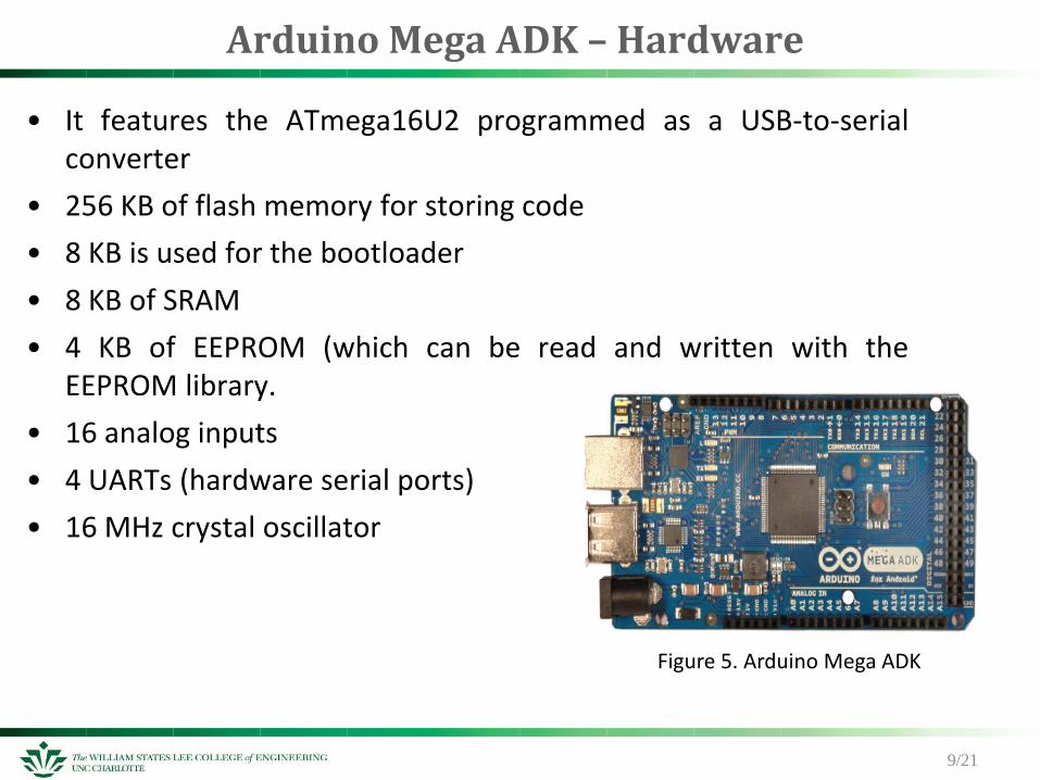
• It features the ATmega16U2 programmed as a USB-to-serial converter
• 256 KB of flash memory for storing code
• 8 KB is used for the bootloader
• 8 KB of SRAM
• 4 KB of EEPROM (which can be read and written with the EEPROM library.
• 16 analog inputs
• 4 UARTs (hardware serial ports)
• 16 MHz crystal oscillator
9/21
Figure 5. Arduino Mega ADK
Arduino Mega ADK – Software Used
10/21
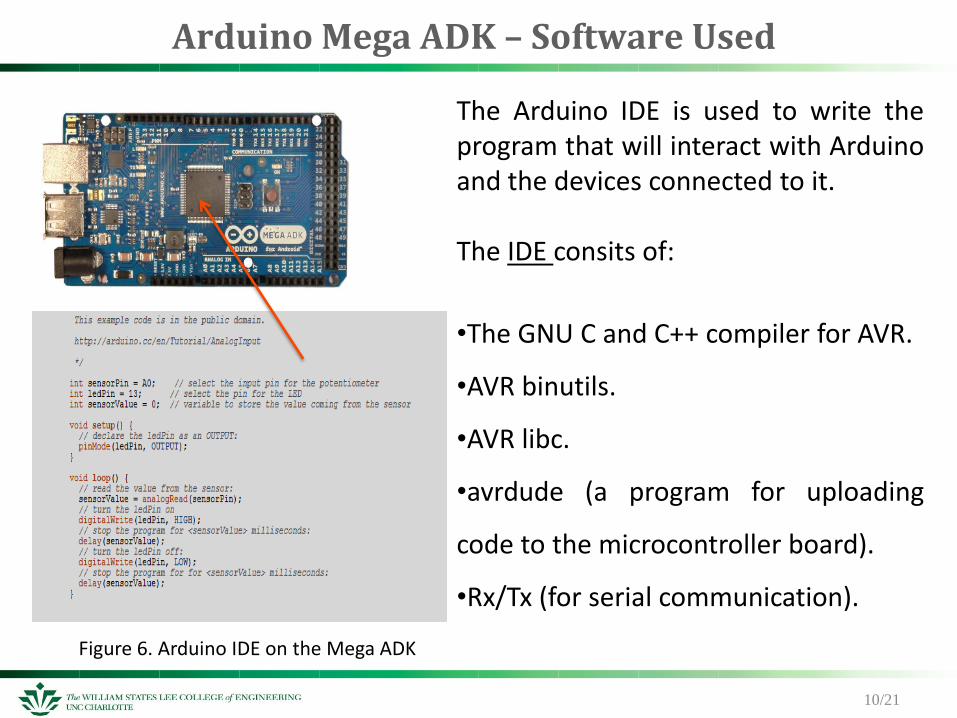
The Arduino IDE is used to write the program that will interact with Arduino and the devices connected to it. The IDE consits of:
•The GNU C and C++ compiler for AVR.
•AVR binutils.
•AVR libc.
•avrdude (a program for uploading
code to the microcontroller board).
•Rx/Tx (for serial communication).
Figure 6. Arduino IDE on the Mega ADK

Atmega 2560 MCU
11/21
The Atmega 2560 is a low-power CMOS 8-bit microcontroller based on the AVR enhanced RISC architecture.
•32 general purpose working registers.
•256K bytes Flash with R/W capabilities.
•4Kbytes EEPROM.
•8 Kbytes SRAM.
• 6 Timer/Counters with compare modes
and PWM.
•10-bit ADC with optional differential input
stage with programmable gain.
•Programmable Watchdog Timer with
Internal Oscillator.
•4 USARTs and an SPI serial port
Figure 7. Atmega 2560 architecture

Scan Tool - ELM 327 Chip & OBD
12/21
•On-board diagnostics(OBD) is an automotive term referring to a vehicle's self-diagnostic and reporting capability. •OBDs use standardized digital communications port to provide real-time data in addition to a standardized series of DTCs (diagnostic trouble codes) •This data helps one to rapidly identify and remedy malfunctions within the vehicle
Figure 8. Scan Tool OBD Connector
Software Implementation
13/21
Data visualization and transmission module - Smartphone.
Provides Encapsulation of data
The Smartphone application retrieves data from the Arduino board and shows them to the users packs and remotely transmits them.
Accessory Development Kit (ADK) - a standard powered by Google, for Android devices to communicate with external hardware.
ADK is the interface between the two modules. (CAN – Arduino MCU board)
ADK advantage - offering an open source OS.

SMaRT CaR - Software
14/21
The Android 3.1 platform introduced Android Open Accessory support. This allowed external USB hardware (an Android USB accessory) to interact with an Android-powered device in a special "accessory" mode. The connected accessory acts as the USB host (powers the bus and enumerates devices) and the Android-powered device acts as the USB device.
Figure 9. Google – Android ADK system Figure 10. Samsung Galaxy Nexus S

Communication Modules
• OBD connectors which provide Bluetooth and Wi-Fi connectivity have been implemented to directly interact with smartphones.
• Communications between sensors and Arduino occur using ZigBee.
15/21
Figure 11. The SMaRT CaR platform.

16/21
Experimental Results
Figure 12. Detailed representation of the SMaRTCaR devices interconnection.

Experimental Results
Data visualization and transmission module:
The software module developed for the smartphone has
the following main functions:
Retrieving data from the Arduino board
Tagging data
Displaying data to the end-user through a
Graphical User Interface (GUI)
Remotely transferring data
17/21
Information retrieved from Arduino + Information gathered by the mobile phone GPS (data, time and position coordinates)
According to their latency and delivery requirements.
Data are tagged with different priorities and lifetimes put into different transmission queues.
Fig. 13. A snapshot of the
developed Android-based
SMaRTCaR application
Experimental Results
18/2`
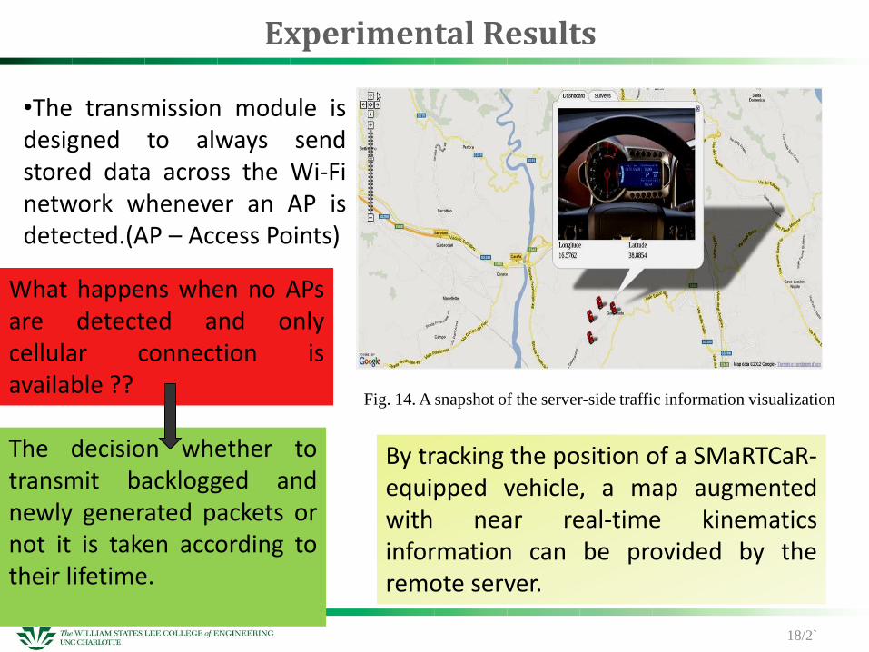
Fig. 14. A snapshot of the server-side traffic information visualization
•The transmission module is designed to always send stored data across the Wi-Fi network whenever an AP is detected.(AP – Access Points)
What happens when no APs are detected and only cellular connection is available ??
The decision whether to transmit backlogged and newly generated packets or not it is taken according to their lifetime.
By tracking the position of a SMaRTCaR-equipped vehicle, a map augmented with near real-time kinematics information can be provided by the remote server.

Conclusion
• It enables the collection of a wide and modular set of measurements (CAN bus-related, other existing solutions and also data coming from environmental sensors).
• Further information is retrieved at no additional expenses.
• The conceived module also manages DTCs reporting information about a sudden vehicle fault in order that they are immediately transmitted over the most reliable and low-latency available connectivity interface.
• Easy-to-use and plug&play solution –
– Connecting the smartphone
– enriched with ad-hoc developed application, to the in-vehicle sensing platform, without additional configuration
19/26

Future Scope
• It can be easily extended to collect new data coming from further sensors, whenever available, in a flexible way
• Further work is required to quantitatively assess the effectiveness of the proposed opportunistic data transfer solution in realistic settings.
• Incentives to the end-users and a business model should be conceived foreseeing cooperation and agreements between all, who are involved. (end-users, Telco operators, and service providers)
20/21
References • [1] T. Watteyne, A. Molinaro, M.G. Richichi, and M. Dohler, ”From MANET To
IETF ROLL Standardization: A Paradigm Shift in WSN Routing Protocols,” IEEE Communications Surveys and Tutorials, vol. 13, no. 4, pp. 688-707, 2011.
• [2] http://www.android.com/
• [3] http://www.wikipedia.org/
• [4] J. Zaldivar, C.T. Calafate, J.C. Cano, and P. Manzoni, “Providing Accident Detection in Vehicular Networks Through OBD-II Devices and Android-based Smartphones,” 5th IEEE Workshop On User Mobility and VEhicular Networks, Bonn, Germany. 4-7 October 2011.
• [5] https://developer.ford.com/community/blogs/
• [6] http://www.scantool.net/elmscan5-compact.html
• [7] http://www.zigbee.org/Products/ByFunction/AllFunctions.aspx
• [8] http://en.wikipedia.org/wiki/Android_Open_Accessory_Development_Kit
• [9] http://arduino.cc/en/
• [10] http://en.wikipedia.org/wiki/Floating_car_data
21/21
Related Documents


