S280 TRC - S300 - S320 TR SMART TOUCH 97050624 Rev.005 2016/10 EN

Welcome message from author
This document is posted to help you gain knowledge. Please leave a comment to let me know what you think about it! Share it to your friends and learn new things together.
Transcript

S280
TR
C -
S300
- S3
20 T
RSM
AR
T TO
UC
H
97050624Rev.0052016/10
EN

3
S280 TRC / S300 / S320 TR - OPERATING INSTRUCTION
3EN
TABLE OF CONTENTS
1. Safety guidelines ..............................................................41.1. Symboldefinition ................................................................41.2. Intendeduse ......................................................................41.2.1. Classificationandreferencestandards ..............................51.2.2. Environmentalconditions ...................................................51.2.2.1.Transportandpackagingconditions ..................................51.2.3. Warranty .............................................................................51.2.4. Disposingtheequipmentwhennolongerused .................51.3. Safetyrules ........................................................................61.4. Cleaninganddisinfecting ...................................................71.5. Sterilization ........................................................................8
2. Description of the equipment .........................................92.1. Nameplate ..........................................................................92.2. Dentalunits ......................................................................102.3. Dentalchair ......................................................................13
3. Turning on the dental operatory ...................................133.1. Invertingtheoperatingunitconfigurationforleft-handed
operators(HYBRIDversiononly) .............................14
4. Dental chair operation ....................................................144.1. Safetydevices ..................................................................154.2. Emergencydevices ..........................................................164.3. Adjustableheadrest .........................................................164.4. Adjustablearmrest(optional) ...........................................17
5. Instrument board operation ..........................................175.1. Doctor’scontrolconsole ...................................................205.1.1. Userinterface ...................................................................225.1.1.1.Operatorselection ............................................................235.1.1.2.Generalsettings ...............................................................235.1.1.2.1. Hygienesystemsettings ...........................................245.1.1.2.1.1.BIOSTERdisinfectioncyclesetting ............................245.1.1.2.1.2.FlushingCYCLESETTING ........................................255.1.1.2.1.3.WHEsystemtankemptying ......................................255.1.1.2.2. Hydrounitsettings ......................................................265.1.1.2.2.1.Bowlwaterdeliverysetting .........................................265.1.1.2.2.2.Cupwaterdeliverysetting ..........................................275.1.1.2.2.3.Automaticbowlmovementsetting ..............................275.1.1.2.3. Footcontroladjustment .............................................285.1.1.2.4. Operatinglampadjustment .......................................285.1.1.2.5. Othersettings ............................................................295.1.1.2.6. Timeanddatesetting ................................................295.1.1.2.7. Chronometer .............................................................305.1.1.2.8. Personalizationoffavouritekeys ................................305.1.1.2.9. Operatordataentry ...................................................315.1.1.2.10.LANGUAGEselection ................................................315.1.1.2.11.APEXLOCATORsetting ............................................315.1.2. Settingthedentalchair’s“rinse”and“home”positions ....325.1.3. ProgrammingthechairpositionsA,B,CandD ..............335.1.4. Emergencystopbutton ....................................................335.1.5. ReductionOfTheBrightnessOfTheOperatingLight. ....335.1.6. SMARTTOUCHscreendisablebutton. ...........................335.2. Footcontrol ......................................................................345.2.1. "Multifunction”footcontrol ................................................345.2.2. "Push-pedal”footcontrol ..................................................355.2.3. "PowerPedal"footcontrol ...............................................375.2.4. Wirelessfootcontrol ........................................................395.3. Syringe .............................................................................415.4. Turbine .............................................................................425.5. Micromotor .......................................................................445.5.1. RESTORATIVEoperatingmode ......................................475.5.2. ENDODONTICoperatingmode .......................................475.5.3. SURGICALoperatingmode .............................................495.5.4. Reductionratiosettingmenu ...........................................50
5.6. Scaler ...............................................................................515.7. TLEDcuringlight (notavailablefortheAmericanand
Canadianmarkets) .....................................................545.8. C-U2dentalcamera. ........................................................575.9. ZEN-Xiintegratedsensor ................................................615.10. Peristalticpump ...............................................................625.11. ElectronicAPEXLOCATOR ............................................63
6. Assistant’s board operation ..........................................646.1. Assistant’stouchpad ........................................................656.2. Syringeonassistant’sboard ............................................666.3. Curinglamponassistant’sboard .....................................666.4. Intraoralcameraonassistant’sboard ..............................666.5. Suctiontubes ...................................................................676.6. Instrumenttray. ................................................................686.7. Hydraulicsalivaejector ...................................................68
7. Hydrogroup operation ...................................................697.1. Fillcupandbowl ..............................................................697.2 SANASPRAYSystem ......................................................717.3. W.H.E.(WaterHygienizationEquipment)system ...........727.4. BIOSTERautomaticdisinfectionsystem .........................747.5. I.W.F.C.system(IntegratedWaterFlushingCycle) ....767.6. ACVSsystem(AutomaticCleaningVacuumSystem). ...77
8. Accessories ....................................................................788.1. Operatinglight .................................................................788.2. Monitoronlamppole .......................................................788.3. Negatoscopeforpanoramas ............................................788.4. Air/water/230Vquick-connectcouplers ............................78
9. Maintenance ...................................................................799.1. Instrumentmaintenance ..................................................799.2. Drainingcondensate ........................................................799.3. Cleaningthesurgicalsuctionfilter ...................................809.4. Surgicalsuction ................................................................809.5. CATTANIsurgicalseparator .............................................819.6 Cleaningtheturbinereturnairfilter ..................................839.7. CATTANIamalgamgravityseparator (S300seriesdental
unitsonly) ...................................................................839.8. METASYSamalgamseparator ........................................839.9. DÜRRamalgamseparator ...............................................839.10. Dentalchair ......................................................................83
10. Fault messages ..............................................................84
11. Specifications .................................................................8511.1. Overalldimensions:S280TRCCONTINENTAL/S280
TRCJCONTINENTAL ...............................................8611.2. Overalldimensions:S280TRCINTERNATIONAL/S280
TRCJINTERNATIONAL ............................................8711.3. Overalldimensions:S300CONTINENTAL ......................8811.4. Overalldimensions:S300INTERNATIONAL ...................8911.5. Overalldimensions:S320TRCONTINENTALHYBRID
version ........................................................................9011.6. S320TRINTERNATIONAL,HYBRIDversiondimensional
characteristics ............................................................91
12. Dental operatory maintenance plan....................................92
4
��
���
�
�
�
�
�
�
� �����
�
��
��
��
��
��
��
��
��
��
��
��
��
��
��
��
S280 TRC / S300 / S320 TR - OPERATING INSTRUCTION
4 EN
1. Safety guidelines
• These instructions explain how to correctly use the following dental units: S280 TRC CONTINENTAL, S280 TRC J CONTINENTAL, S280 TRC INTERNATIONAL, S280 TRC J INTERNATIONAL, S300 CONTINENTAL,
S300 INTERNATIONAL, S320 TR CONTINENTAL HYBRID version, S320 TR INTERNATIONAL HYBRID version. Carefully read and become familiar with the content of this manual before using the equipment.• Theseinstructionsdescribealltheversionsoftheoperatingunitswiththemaximumpossibleaccessories,thereforenotalltheparagraphsareapplicabletotheunityouhavepurchased.
•Nopartofthismanualistobereproduced,storedinaretrievalsystemortransmittedinanyformorbyanymeans,i.e.electronic,mechanical,photocopying,translationorotherwise,withoutthepriorwrittenpermissionofCEFLAs.c.
•Theinformation,specificationsandillustrationscontainedinthispublicationarenotbinding. CEFLAs.c.reservestherighttomaketechnicalimprovementsandchangeswithoutmodifyingtheinstructionscontainedherein.•Themanufacturerhasacompanypolicyofcontinualdevelopment.Althougheveryeffortismadetokeeptechnicaldocumentationup-to-dateatalltimesthemanualmaynotcorrespondexactlytocurrentspecifications.Themanufacturerreservestherighttomakechangeswithoutpriornotice.
•TheoriginalversionofthismanualiswritteninItalian.•Thisequipmentisequippedwithadevicethatpreventsliquidbackup.
1.1. Symboldefinition
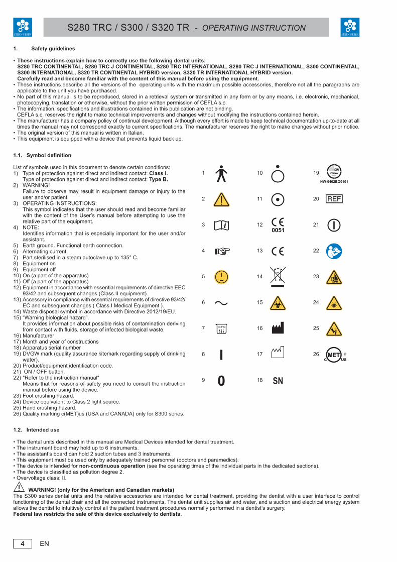
Listofsymbolsusedinthisdocumenttodenotecertainconditions:1) Typeofprotectionagainstdirectandindirectcontact:Class I. Typeofprotectionagainstdirectandindirectcontact:Type B.2) WARNING! Failure toobservemayresult inequipmentdamageor injury to the
userand/orpatient.3) OPERATINGINSTRUCTIONS: Thissymbolindicatesthattheusershouldreadandbecomefamiliar
with thecontentof theUser’smanualbeforeattempting touse therelativepartoftheequipment.
4) NOTE: Identifiesinformationthatisespeciallyimportantfortheuserand/or
assistant.5) Earthground.Functionalearthconnection.6) Alternatingcurrent7) Partsterilisedinasteamautoclaveupto135°C.8) Equipmenton9) Equipmentoff10)On(apartoftheapparatus)11)Off(apartoftheapparatus)12)EquipmentinaccordancewithessentialrequirementsofdirectiveEEC
93/42andsubsequentchanges(ClassIIequipment).13)Accessoryincompliancewithessentialrequirementsofdirective93/42/
ECandsubsequentchanges(ClassIMedicalEquipment).14)WastedisposalsymbolinaccordancewithDirective2012/19/EU.15)“Warningbiologicalhazard”. Itprovidesinformationaboutpossiblerisksofcontaminationderiving
fromcontactwithfluids,storageofinfectedbiologicalwaste.16)Manufacturer17)Monthandyearofconstructions18)Apparatusserialnumber19)DVGWmark(qualityassurancekitemarkregardingsupplyofdrinking
water).20)Product/equipmentidentificationcode.21) ON/OFFbutton.22)"Refertotheinstructionmanual" Meansthatforreasonsofsafetyyouneedtoconsulttheinstruction
manualbeforeusingthedevice.23)Footcrushinghazard.24)DeviceequivalenttoClass2lightsource.25)Handcrushinghazard.26)Qualitymarkingc(MET)us(USAandCANADA)onlyforS300series.
1.2. Intended use
•ThedentalunitsdescribedinthismanualareMedicalDevicesintendedfordentaltreatment.•Theinstrumentboardmayholdupto6instruments.•Theassistant’sboardcanhold2suctiontubesand3instruments.•Thisequipmentmustbeusedonlybyadequatelytrainedpersonnel(doctorsandparamedics).•Thedeviceisintendedfornon-continuous operation(seetheoperatingtimesoftheindividualpartsinthededicatedsections).•Thedeviceisclassifiedaspollutiondegree2.•Overvoltageclass:II.
WARNING! (only for the American and Canadian markets)TheS300seriesdentalunitsandtherelativeaccessoriesareintendedfordentaltreatment,providingthedentistwithauserinterfacetocontrolfunctioningofthedentalchairandalltheconnectedinstruments.Thedentalunitsuppliesairandwater,andasuctionandelectricalenergysystemallowsthedentisttointuitivelycontrolallthepatienttreatmentproceduresnormallyperformedinadentist’ssurgery.Federal law restricts the sale of this device exclusively to dentists.
5
S280 TRC / S300 / S320 TR - OPERATING INSTRUCTION
5EN
1.2.3. Warranty
CEFLAs.c.standsbehinditsproductswarrantingsafety,reliabilityandperformance.Thewarrantyisvalidonlyunderthefollowingterms:•Theconditionsgivenonthewarrantycertificateareobserved.•Theequipmentisusedonlyasinstructedinthismanual.•TheelectricalwiringintheroominwhichtheequipmentisinstalledmustconformtoIEC60364-7-710(standardsforelectricalwiringinmedicalanddentaloffices).
•A3x1.5mm2lineprotectedbyabi-polarcut-outthatconformstoapplicablestandards(10A,250V,distancebetweencontactsatleast3mm)mustbeusedtofeedtheequipment.
WARNING! The color of the three wires (POWER, NEUTRAL and EARTH) should satisfy the requirements of current standards.• Installation,repairsand,ingeneral,anyotheroperationsrequiringthecasingtobeopenedaretobeperformedexclusivelybypersonnelauthorizedbySTERNWEBER.
1.2.4. Disposing the equipment when no longer used
Assetout inDirectives2011/65/ECand2012/19/EC,on therestrictionsof theuseofcertainhazardoussubstances inelectricalandelectronicequipmentalongwithcollection,treatment,recyclinganddisposalofwasteelectricalandelectronicequipmentthelattermustbetreatedasmunici-palwaste,thereforesortedandcollectedseparately.Whennewequipmentofequivalenttypeispurchasedthewasteequipmentshouldbereturnedtothedistributoronaone-to-onebasisfordisposal.Asfarasreuse,recyclingandotherformsofwasterecoverymentionedaboveareconcerned,themanufacturerisresponsiblefortheactionsspecifiedbyindividuallocallaws.Efficientcollectionofsortedwasteseparatelytorecycleandtreatwasteelectricalandelectronicequipmentaidsinpreventingnegativeenvironmentalimpactswhileprotectinghumanhealth.Inadditionitfacilitatesrecyclingofthematerialsusedtoconstructtheequipment.Illegalwastedisposalcarriesheavyfinesdefinedbylocallaws.
WARNING! The crossed out wheeled bin placed on the equipment indicates that the waste equipment must be collected separately from other waste.
1.2.1. Classificationandreferencestandards
• MEDICALDEVICESclassification ClassificationofthedentalunitinaccordancewiththeindicationsgiveninannexIXofdirective93/42/EECandsubsequentchanges:Class IIa.• ELECTRICALMEDICALEQUIPMENTclassification ClassificationofthedentalunitinaccordancewithstandardI.E.C.60601-1forsafetyofmedicalequipment:Class I - Type B.• Referencestandards:thedentalunitsdescribedinthismanualaredesignedandmanufacturedincompliancewithIEC60601-13rdEd.-2007,IEC60601-1-63rdEd.-2010,IEC623661stEd.-2007,IEC80601-2-601stEd.-2012,IEC60601-1-23rdEd.,ISO68753rdEd.-2011,ISO7494-12ndEd.-2011andEN1717(typeAAandAB)standardsasfaraswatermainssafetydevicesareconcerned.
• ClassificationofRADIODEVICESANDCOMMUNICATIONTERMINALS(onlywhentheWIRELESSfootcontrolispresent) EquipmentclassificationaccordingtoDirective99/05/ECArt.12:Class I.
1.2.2. Environmental conditions
Theequipmentistobeinstalledinroomsthatsatisfythefollowingrequirements:• temperaturebetween10and40°C.• relativehumiditybetween30and75%.•atmosphericpressurerangingfrom700to1060hPa.•altitude≤3000m;•airpressureenteringequipmentrangingfrom6to8bar.•waterhardnessattheequipmentinletmustnotbeabove25°f(Frenchdegrees)or14°d(Germandegrees)foruntreateddrinkingwater.Forwaterwithahigherhardnessdegree,itisrecommendedtosoftenwateruntilitreachesahardnessdegreebetween15and25°f(Frenchdegrees)orbetween8.4and14°d(Germandegreees);
•waterpressureenteringequipmentrangingfrom3to5bar.•watertemperatureenteringequipmentnothigherthan25°C.
1.2.2.1. Transport and packaging conditions
•Temperature:from-10to70°C;•Relativehumidity:from10%to90%;•Atmosphericpressure:from500to1060hPa.
6
S280 TRC / S300 / S320 TR - OPERATING INSTRUCTION
6 EN
1.3. Safety rules
WARNING! • All equipment is permanently installed. Dependingonthetypeofchairtheunitcomeswith,refertotheinstallationDATAgiveninparagraph“Specifications”. CEFLA s.c. shall not be held liable for any personal injury or equipment damage resulting from failure to heed the precaution given above.• Floor condition Thefloorconditions(continuoustype)mustmeetdesignloadstandardssetforthinDIN1055sheet3. Theweightofthedentalunitincludingapatientweighing190Kg,isapproximately350Kg. Inthecaseoffloorinstallationwithouttheuseofaloadplate,thecharacteristicsofthefloormustassurethebreakingstrengthoftheanchorboltsisnotlessthan1200daNeach(consideringRckcementstrength20MPa).Inthecaseoffloorinstallationwiththeuseofaloadplate,thefloormustassurethebreakingstrengthoftheanchorboltsisnotlessthan260daN.
SeetheInstallationmanualforfurtherdetailsaboutinstallation. The positions of the connections for the distribution and drain lines comply to standard UNI EN ISO 11144.•Thisdevicemaynotbemodifiedinanywaywithouttheauthorisationofthemanufacturer.Ifthedeviceismodified,appropriateexaminationsandtestsneedtobeconductedinordertoensurecontinuedsafeuse. CEFLA s.c. shall not be held liable for any personal injury or equipment damage resulting from failure to heed the precaution given above.• Dental chair Themaximumchaircapacityis190Kg.Thisweightmustneverbeexceeded.• Tray holders Themaximumweightsthatcanbeheldmustneverbeexceeded: -Instrumenttrayattachedtotheinstrumentboardmaximumallowableload2Kg,evenlydistributed. -Instrumenttrayattachedtotheinstrumentboardmaximumallowableload1Kg,evenlydistributed.• Electromagnetic interferences. UseofelectricalequipmentthatdoesnotcomplytostandardIEC 60601-1 3.a Ed. - 2007intheofficeornearbymaycauseelectromagneticorothertypesofinterferencesresultingindentalunitmalfunctions.
Inthesecases,shutoffpowertothedentalunitbeforeusingthisequipment.• Replacing the drills Operatetheturbinereleaseandcontra-angledevicesonlyoncethedrillhascometoacompletestop.Failuretodoso,willresultindamagingthelockingsystemanddrillscouldbereleasedandcauseinjury.Exclusivelyusehigh-qualitydrillswithaconnectionhavingacalibrateddiameter.Tochecktheconditionsofthelockingsystem,makesurethedrillisfirmlysecuredtotheinstrumenteverydaybeforestartingwork.Lockingsystemdefectscausedbymisusecanbeeasilyidentifiedandarenotcoveredbythewarranty.
ThedrillsandthevariousinstrumentsattachedtothehandpiecesmustcomplywithBiocompatibilityStandardISO10993.• Patients with pace makers and/or hearing aids. Whentreatingpatientswithpacemakersand/orhearingaids,takeintoconsiderationtheeffectstheinstrumentsmayhaveonpacemakersand/orhearingaids.Carefullyreadtechnical-scientificinformationavailableonthissubject.
• Implants. Ifthedentalunitisusedforimplantoperationsusingseparateequipmentdesignedforthispurpose,shutoffpowertothedentalchairtoavoidunwantedmovementsresultingfromfaultsand/oraccidentalstartupofthecontrols.
•Donotforgettoturnofftheoffice’swatersupplyandmasterswitchontheequipmentbeforeleavingthesurgery.•Theequipmentisnotprotectedagainstliquidpenetration(IPXO).•Thisequipmentisnotsuitableforuseinthepresenceofamixofinflammableanaestheticgaswithoxygenornitrousoxide.•Thisequipmentmustbestoredproperlysothatitiskeptintopworkingorderatalltimes.Themanufacturershallnotbeheldresponsibleformisuse,carelessnessorimproperuseoftheequipment.
•Thisequipmentistobeusedexclusivelybyqualifiedpersonnel(doctorsandparamedics)withthepropertraining.•Theusermustbepresentatalltimeswhentheequipmentisturnedonorreadyforstart-up.Inparticular,neverleavetheequipmentunattendedinthepresenceofchildren/thementallydisabledorotherunauthorisedpersonnelingeneral.
Anycompanionsmustkeepoutoftheareainwhichtreatmentisperformedandinanycaseundertheresponsibilityoftheoperator.Theareainwhichtreatmentisperformedreferstothespacearoundthedentalunitplus1.5meters.
• Quality of the water delivered by the dental unit. Theuserisresponsibleforthequalityofthewaterdeliveredbythedentalunitandmustadoptmeasurestomaintainit.Toensurethatyoumeetthewaterqualityrequirements,CEFLAs.c.advisesyoutoequipthedentalunitwithaninternalorexternaldisinfectionsystem.Onceinstalled,thedentalunitisexposedtocontaminantsoriginatingfromthewatersupply.Forthisreason,itisrecommendedtoinstallandputitintooperationonlywhenyoubeginusingitdailyandtoperformthedecontaminationproceduresdescribedintherelativechaptersrightfromthefirstdayofinstallation.Ifthedentalunitisequippedwithadeviceforseparationfromtheopenwatersupplysystem(EN1717),makesurethatitalsocontinuouslyaddsdisinfectantasrequiredandcheckthattherelativetankcontainsanadequatequantity(seetherelativeparagraph).
NOTE: Contact your local dealer or Dental association for more detailed information about national laws and requirements.• Applied Parts.Thepartsofthedevicethatduringnormalusenecessarilycomeintocontactwiththepatientforthedevicetobeabletoperformitsfunctionsare:Dentalchairupholstery,armrest,polymerisinglampfibreoptics,terminalpartofthesyringe,single-usecameraprotection,scalerbits,drillhand-pieces,cannulasuctionterminals.
Nonappliedpartsthatmaycomeintocontactwiththepatientare:dentalchairarmrestsupport,dentalchairlowercasing,patient-sidehydrounitcasing,cupwaterdeliveryspout,bowl,suctiontubes,handpiecebody.
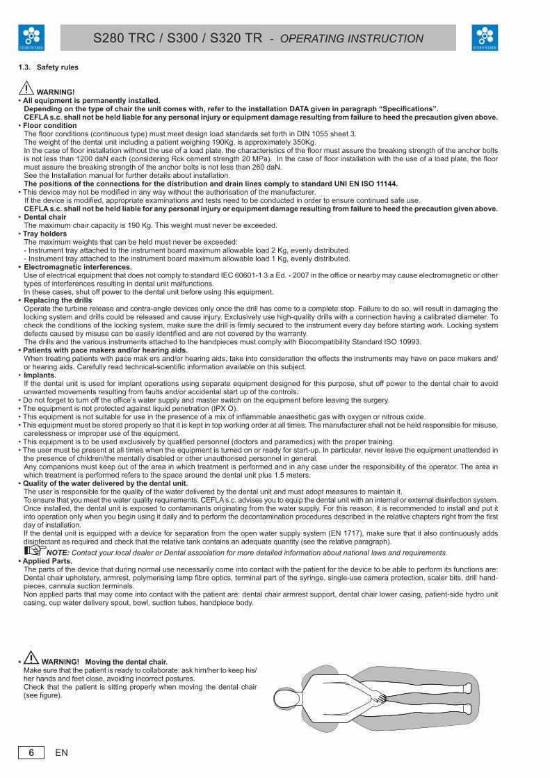
• WARNING! Moving the dental chair.Makesurethatthepatientisreadytocollaborate:askhim/hertokeephis/herhandsandfeetclose,avoidingincorrectpostures.Check that thepatient issittingproperlywhenmoving thedentalchair(seefigure).
7
S280 TRC / S300 / S320 TR - OPERATING INSTRUCTION
7EN
1.4. Cleaning and disinfecting
Cleaningisthefirststepofanydisinfectingprocess.Physicallyscrubbingwithdetergentsandsurface-activesubstancesandrinsingwithwaterremovesaconsiderableamountofmicroorganisms.Ifasurfaceisnotcleanfirst,thedisinfectingprocesscannotbesuccessful.Ifasurfacecannotbeadequatelycleaned,itshouldbeprotectedwithbarriers.TheouterpartsoftheequipmentmustbecleanedanddisinfectedusingaproductforhospitalusewithindicationsforHIV,HBVandtubercolocide(medium-leveldisinfectant)specificallyforsmallsurfaces.Thevariousdrugsandchemicalproductsusedindentist’ssurgeriesmaydamagethepaintedsurfacesandtheplasticparts.Researchandtestsrunshowthatthesurfacescannotbefullyprotectedagainsttheharshactionofallproductsavailableonthemarket.Wethereforerecommendprotectingwithbarrierswheneverpossible.Theharshactionsofchemicalproductsalsodependontheamountoftimetheyareleftonthesurfaces.Itisthereforeimportantnottoleavetheproductonthesurfaceslongerthanthetimespecifiedbythemanufacturer.
Itisrecommendedtousethespecificmedium-leveldisinfectant,STER1PLUS(CEFLAs.c.),whichiscompatiblewith:• Coated surfaces and plastic parts.• Upholstery.
WARNING!Any splashes or spots of mordant will stain the MEMORY FOAM upholstery. Immediately rinse with plenty of water if acid spatters on the upholstery.• Uncoated metal surfaces.
IfyoudonotuseSTER1PLUS,itisrecommendedtouseproductsthatcontainatmaximum:• Ethanol. Concentration: maximum30gper100gofdisinfectant.• 1-propanol (N-propanol, propyl alcohol, N-propyl alcohol). Concentration:maximum20gper100gofdisinfectant.• Combination of ethanole and propanole.Concentration:thecombinationofthetwoshouldbemaximum40gper100gofdisinfectant.
WARNING!• Do not use products containing isopropyl alcohol (2-propanol,iso-propanol).• Do not use products that contain sodium hypochlorite (bleach).• Do not use cleaners that contain phenol. • Do not spray the selected products directly on the surfaces.• All products must be used as directed by the manufacturer.• Do not mix the STER 1 PLUS disinfectant with other products.
WARNING!The products suggested are compatible with the materials of the equipment, however damages may occur to surfaces and materials re-sultingfromtheuseofdifferentproducts,evenifnotincludedintheabovelistofexcludedproducts.
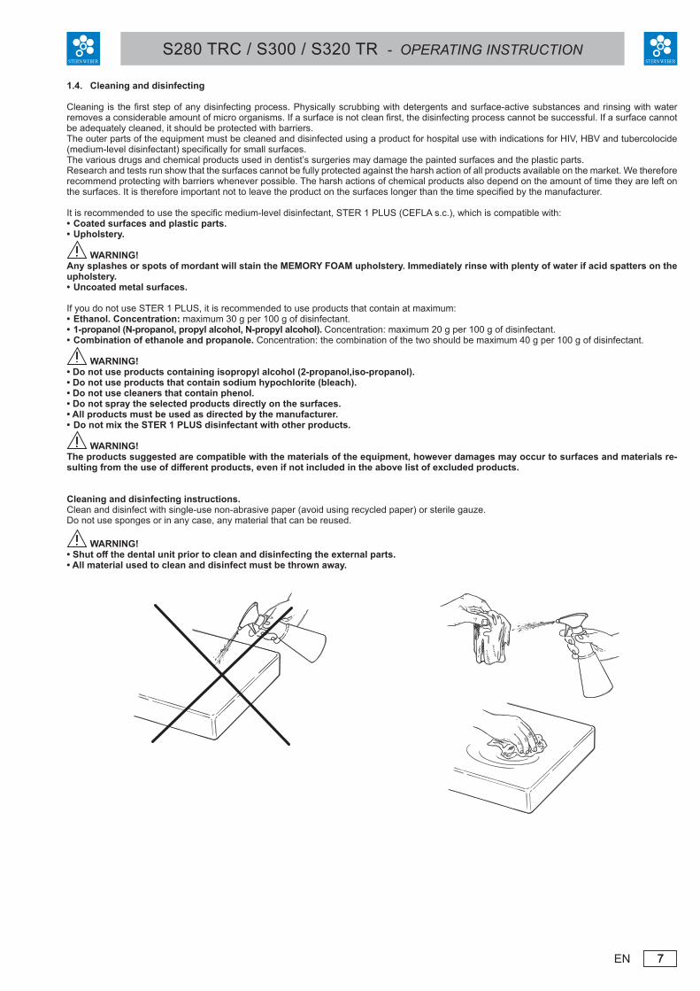
Cleaning and disinfecting instructions.Cleananddisinfectwithsingle-usenon-abrasivepaper(avoidusingrecycledpaper)orsterilegauze.Donotusespongesorinanycase,anymaterialthatcanbereused.
WARNING!•Shutoffthedentalunitpriortocleananddisinfectingtheexternalparts.• All material used to clean and disinfect must be thrown away.
8
S280 TRC / S300 / S320 TR - OPERATING INSTRUCTION
8 EN
1.5. Sterilization
EachinstrumentissuppliedNOTSTERILEandmustbesterilizedinasteamautoclave(max135°C)beforeuse,avoidinganyformofchemicalsterilization.Sterilizationmustbeperformedusingsuitablepackagingmaterialscheckedduringthesterilizationprocessvalidation.Werecommendsterilizinginsteamautoclave(moistheat)usingapre-vacuum(forcedairremoval)cycle.Autoclavesmustcomplywiththerequirementsof,bevalidatedbyandmaintainedinaccordancewithEN13060(orANSI/AAMIST55),ENISO17665-1andANSI/AAMIST79.
Seebelowforrecommendedminimumsterilizationparametersforre-usablemedicaldevicesthathavebeenvalidatedtoprovidea10^-6sterilityassurancelevel(SAL):•CycleTypewithpre-vacuum(Pre-vac).•Method:"overkill"moistheatsterilizationincompliancewithISO17665-1.•Minimumtemperature:134°C(273°F)forheat-resistantmaterials(instrumentsandmetallichandpieces,etc);121°C(250°F)forheat-labilematerials(rubberproducts,etc.).•Minimumexposuretime(1):4minutes(at134°C),20minutes(at120°C).•Minimumdryingtime(2):definedtoensurecompliancewiththerequirementsofEN13060(orANSI/AAMIST55).
(1)Exposuretime:periodoftimeduringwhichtheloadandtheentirechamberaremaintainedabovesterilizationtemperature.(2)DRYINGTIME:periodoftimeduringwhichsteamisremovedfromthechamberandthechamber'spressureisreducedtoallowevaporationofcondensatefromtheloadeitherbyprolongedevacuationorbytheinjectionandextractionofhotairorothergases.Thedryingtimevariesaccordingtoloadconfiguration,typeofpackagingandmaterials.
9
S280 TRC / S300 / S320 TR - OPERATING INSTRUCTION
9EN
2. Description of the equipment
2.1. Nameplate
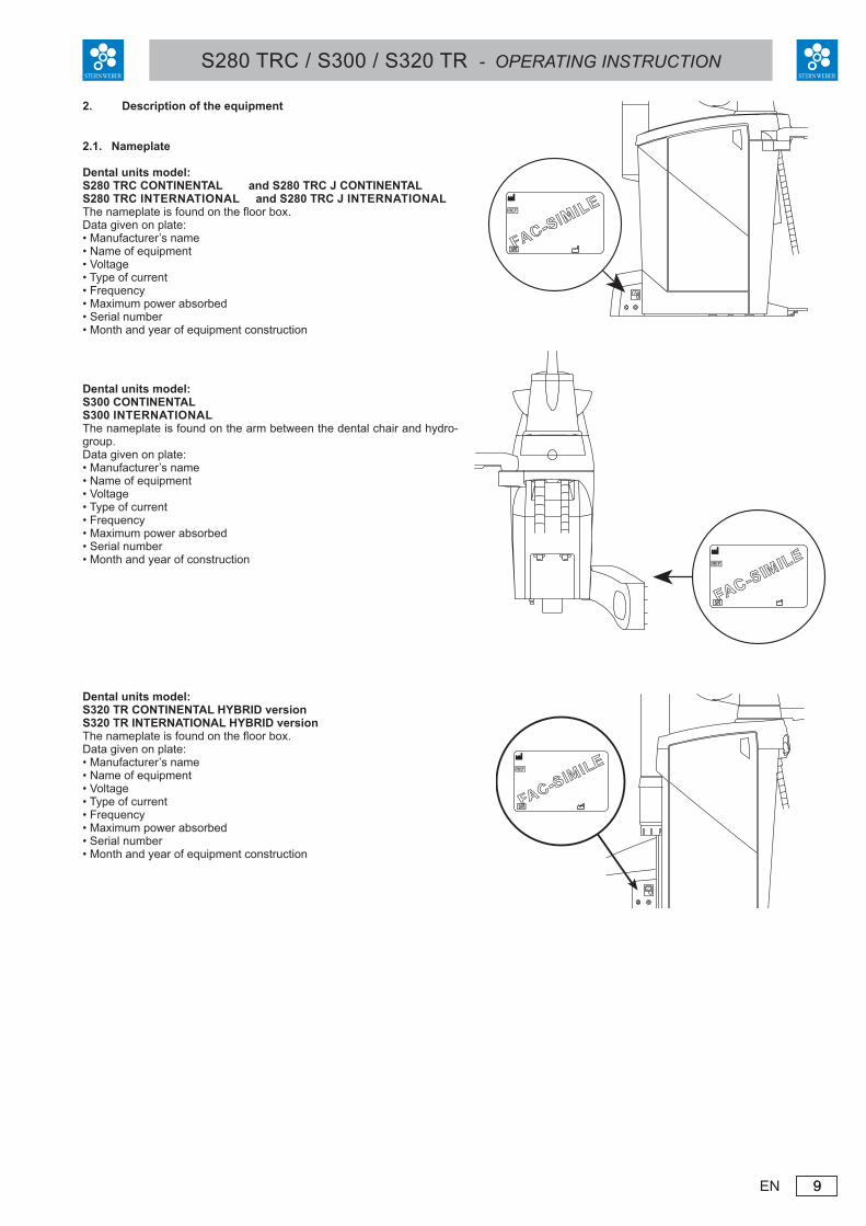
Dental units model: S280 TRC CONTINENTAL and S280 TRC J CONTINENTALS280 TRC INTERNATIONAL and S280 TRC J INTERNATIONALThenameplateisfoundonthefloorbox.Datagivenonplate:•Manufacturer’sname•Nameofequipment•Voltage•Typeofcurrent•Frequency•Maximumpowerabsorbed•Serialnumber•Monthandyearofequipmentconstruction
Dental units model: S300 CONTINENTALS300 INTERNATIONALThenameplateisfoundonthearmbetweenthedentalchairandhydro-group.Datagivenonplate:•Manufacturer’sname•Nameofequipment•Voltage•Typeofcurrent•Frequency•Maximumpowerabsorbed•Serialnumber•Monthandyearofconstruction
Dental units model: S320 TR CONTINENTAL HYBRID versionS320 TR INTERNATIONAL HYBRID versionThenameplateisfoundonthefloorbox.Datagivenonplate:•Manufacturer’sname•Nameofequipment•Voltage•Typeofcurrent•Frequency•Maximumpowerabsorbed•Serialnumber•Monthandyearofequipmentconstruction
10
� �� �
�
�
�
�
�� �
�
�
��
� �� �
�
��
��� �
�
�
��
�
S280 TRC / S300 / S320 TR - OPERATING INSTRUCTION
10 EN
2.2. Dental units
ThedentalunitsoftheS280TRCseriescomeinthefollowingmodels:
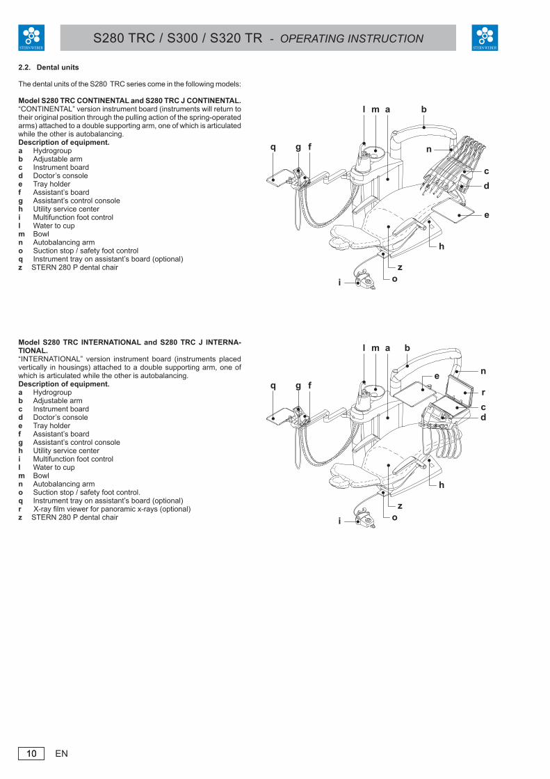
Model S280 TRC CONTINENTAL and S280 TRC J CONTINENTAL.“CONTINENTAL”versioninstrumentboard(instrumentswillreturntotheiroriginalpositionthroughthepullingactionofthespring-operatedarms)attachedtoadoublesupportingarm,oneofwhichisarticulatedwhiletheotherisautobalancing.Description of equipment.a Hydrogroupb Adjustablearmc Instrumentboardd Doctor’sconsolee Trayholderf Assistant’sboardg Assistant’scontrolconsoleh Utilityservicecenteri Multifunctionfootcontroll Watertocupm Bowln Autobalancingarmo Suctionstop/safetyfootcontrolq Instrumenttrayonassistant’sboard(optional)z STERN280Pdentalchair
Model S280 TRC INTERNATIONAL and S280 TRC J INTERNA-TIONAL.“INTERNATIONAL” version instrument board (instruments placedvertically inhousings)attachedtoadoublesupportingarm,oneofwhichisarticulatedwhiletheotherisautobalancing.Description of equipment.a Hydrogroupb Adjustablearmc Instrumentboardd Doctor’sconsolee Trayholderf Assistant’sboardg Assistant’scontrolconsoleh Utilityservicecenteri Multifunctionfootcontroll Watertocupm Bowln Autobalancingarmo Suctionstop/safetyfootcontrol.q Instrumenttrayonassistant’sboard(optional)r X-rayfilmviewerforpanoramicx-rays(optional)z STERN280Pdentalchair
11
�
�
�
�
��
�
� �
��
�
�
�
�
��
��
�
� �
��
�
�
��
�
�
�
��
� �
�
� �
�
��
�
S280 TRC / S300 / S320 TR - OPERATING INSTRUCTION
11EN
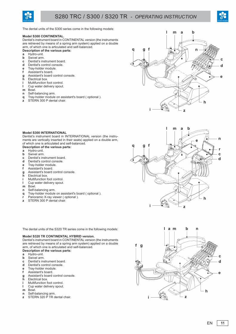
ThedentalunitsoftheS300seriescomeinthefollowingmodels:
Model S300 CONTINENTAL.Dentist’sinstrumentboardinCONTINENTALversion(theinstrumentsareretrievedbymeansofaspringarmsystem)appliedonadoublearm,ofwhichoneisarticulatedandself-balanced.Description of the various parts: a Hydro-unit.b Swivelarm.c Dentist’sinstrumentboard.d Dentist'scontrolconsole.e Tray-holdermodule.f Assistant'sboard.g Assistant'sboardcontrolconsole.h Electricalbox.i Multifunctionfootcontrol.l Cupwaterdeliveryspout.m Bowl.n Self-balancingarm.q Tray-holdermoduleonassistant'sboard(optional).z STERN300Pdentalchair.
Model S300 INTERNATIONALDentist’s instrumentboard in INTERNATIONALversion(the instru-mentsareverticallyinsertedintheirseats)appliedonadoublearm,ofwhichoneisarticulatedandself-balanced.Description of the various parts:a Hydro-unit.b Swivelarm.c Dentist’sinstrumentboard.d Dentist'scontrolconsole.e Tray-holdermodule.f Assistant'sboard.g Assistant'sboardcontrolconsole.h Electricalbox.i Multifunctionfootcontrol.l Cupwaterdeliveryspout.m Bowl.n Self-balancingarm.q Tray-holdermoduleonassistant'sboard(optional).r PanoramicX-rayviewer(optional).z STERN300Pdentalchair.
ThedentalunitsoftheS320TRseriescomeinthefollowingmodels:
Model S320 TR CONTINENTAL HYBRID version.Dentist’sinstrumentboardinCONTINENTALversion(theinstrumentsareretrievedbymeansofaspringarmsystem)appliedonadoublearm,ofwhichoneisarticulatedandself-balanced.Description of the various parts: a Hydro-unit.b Swivelarm.c Dentist’sinstrumentboard.d Dentist'scontrolconsole.e Tray-holdermodule.f Assistant'sboard.g Assistant'sboardcontrolconsole.h Electricalbox.i Multifunctionfootcontrol.l Cupwaterdeliveryspout.m Bowl.n Self-balancingarm.z STERN320PTRdentalchair.
12
�
� �
�
� �
�
��
�
���
�
S280 TRC / S300 / S320 TR - OPERATING INSTRUCTION
12 EN
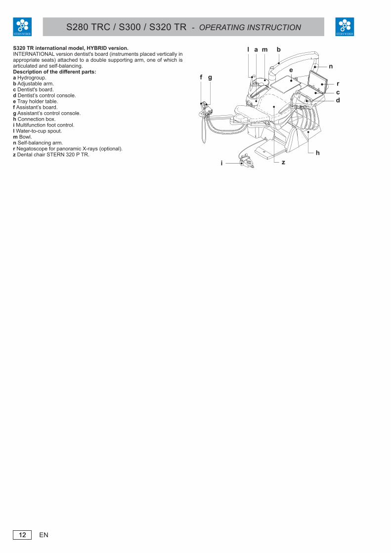
S320 TR international model, HYBRID version.INTERNATIONALversiondentist'sboard(instrumentsplacedverticallyinappropriateseats)attachedtoadoublesupportingarm,oneofwhichisarticulatedandself-balancing.Descriptionofthedifferentparts:aHydrogroup.bAdjustablearm.cDentist'sboard.dDentist’scontrolconsole.eTrayholdertable.f Assistant’sboard.gAssistant’scontrolconsole.hConnectionbox.i Multifunctionfootcontrol.lWater-to-cupspout.mBowl.nSelf-balancingarm.rNegatoscopeforpanoramicX-rays(optional).zDentalchairSTERN320PTR.
13
�
���
�
�
���
�
��
�
��
S280 TRC / S300 / S320 TR - OPERATING INSTRUCTION
13EN
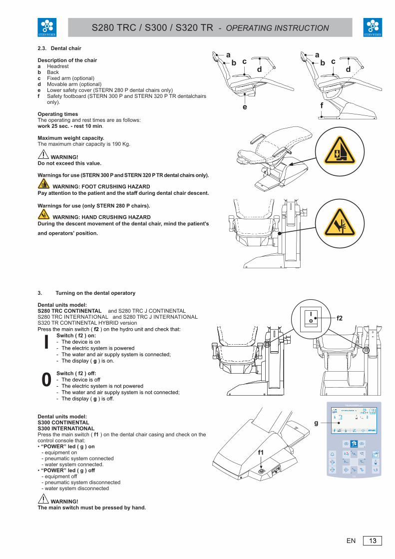
2.3. Dental chair
Description of the chaira Headrestb Backc Fixedarm(optional)d Movablearm(optional)e Lowersafetycover(STERN280Pdentalchairsonly)f Safetyfootboard(STERN300PandSTERN320PTRdentalchairs only).
Operating timesTheoperatingandresttimesareasfollows:work 25 sec. - rest 10 min.
Maximum weight capacity.Themaximumchaircapacityis190Kg.
WARNING!Do not exceed this value.
Warnings for use (STERN 300 P and STERN 320 P TR dental chairs only).
WARNING: FOOT CRUSHING HAZARDPayattentiontothepatientandthestaffduringdentalchairdescent.
Warnings for use (only STERN 280 P chairs).
WARNING: HAND CRUSHING HAZARDDuring the descent movement of the dental chair, mind the patient's
and operators' position.
3. Turning on the dental operatory
Dental units model: S280 TRC CONTINENTAL andS280TRCJCONTINENTALS280 TRC INTERNATIONAL andS280TRCJINTERNATIONALS320TRCONTINENTALHYBRIDversionPressthemainswitch(f2)onthehydrounitandcheckthat: Switch ( f2 ) on: - Thedeviceison - Theelectricsystemispowered - Thewaterandairsupplysystemisconnected; - Thedisplay(g)ison.
Switch(f2)off: - Thedeviceisoff - Theelectricsystemisnotpowered - Thewaterandairsupplysystemisnotconnected; - Thedisplay(g)isoff.
Dental units model: S300 CONTINENTALS300 INTERNATIONALPressthemainswitch(f1)onthedentalchaircasingandcheckonthecontrolconsolethat:• “POWER”led(g)on -equipmenton -pneumaticsystemconnected -watersystemconnected.• “POWER”led(g)off -equipmentoff -pneumaticsystemdisconnected -watersystemdisconnected
WARNING!The main switch must be pressed by hand.
14
�
�
�
�
S280 TRC / S300 / S320 TR - OPERATING INSTRUCTION
14 EN
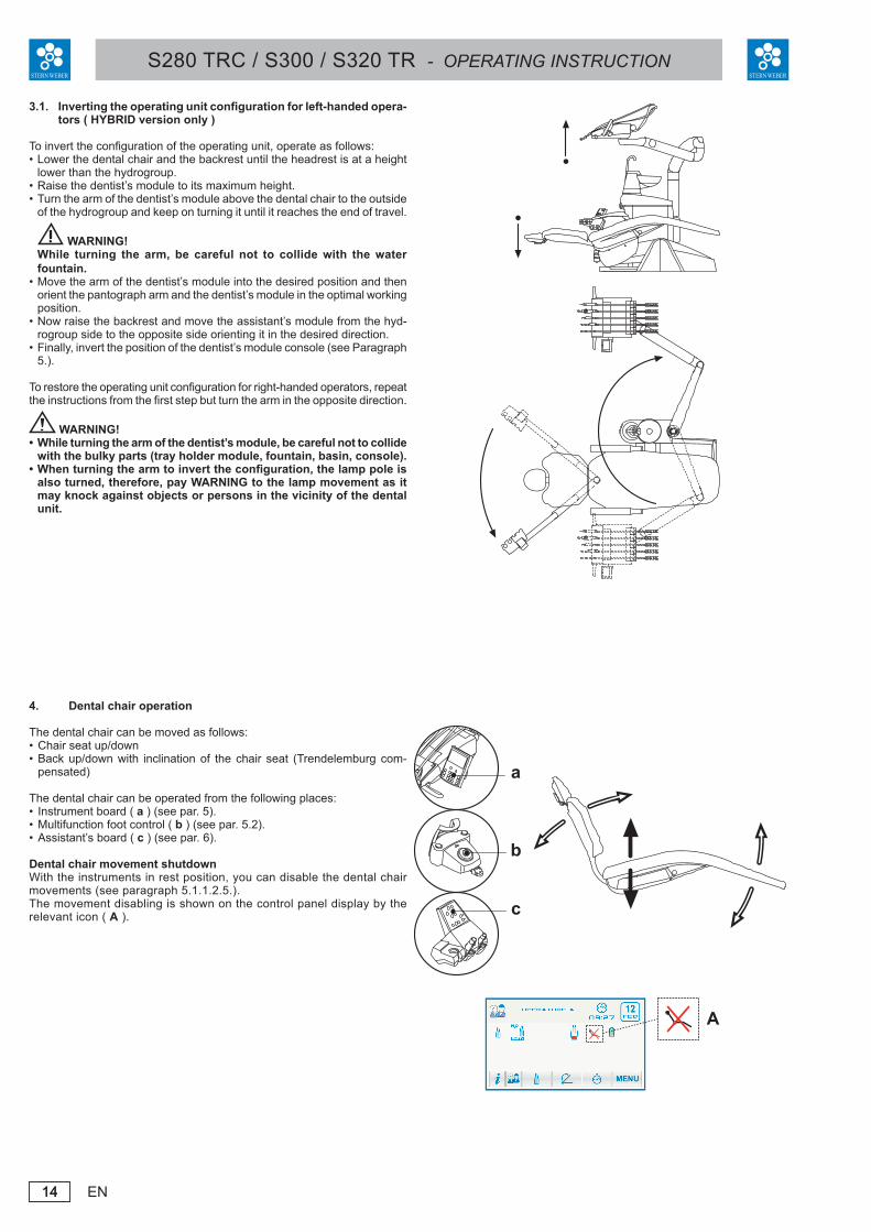
3.1. Invertingtheoperatingunitconfigurationforleft-handedopera-tors ( HYBRID version only )
Toinverttheconfigurationoftheoperatingunit,operateasfollows:•Lowerthedentalchairandthebackrestuntiltheheadrestisataheightlowerthanthehydrogroup.
•Raisethedentist’smoduletoitsmaximumheight.•Turnthearmofthedentist’smoduleabovethedentalchairtotheoutsideofthehydrogroupandkeeponturningituntilitreachestheendoftravel.
WARNING!While turning the arm, be careful not to collide with the water fountain.
•Movethearmofthedentist’smoduleintothedesiredpositionandthenorientthepantographarmandthedentist’smoduleintheoptimalworkingposition.
•Nowraisethebackrestandmovetheassistant’smodulefromthehyd-rogroupsidetotheoppositesideorientingitinthedesireddirection.
•Finally,invertthepositionofthedentist’smoduleconsole(seeParagraph5.).
Torestoretheoperatingunitconfigurationforright-handedoperators,repeattheinstructionsfromthefirststepbutturnthearmintheoppositedirection.
WARNING!• While turning the arm of the dentist’s module, be careful not to collide
with the bulky parts (tray holder module, fountain, basin, console).•Whenturningthearmtoinverttheconfiguration,thelamppoleis
also turned, therefore, pay WARNING to the lamp movement as it may knock against objects or persons in the vicinity of the dental unit.
4. Dental chair operation
Thedentalchaircanbemovedasfollows:•Chairseatup/down•Backup/downwith inclinationof thechair seat (Trendelemburgcom-pensated)
Thedentalchaircanbeoperatedfromthefollowingplaces:• Instrumentboard(a )(seepar.5).•Multifunctionfootcontrol(b )(seepar.5.2).•Assistant’sboard(c )(seepar.6).
Dental chair movement shutdownWiththeinstrumentsinrestposition,youcandisablethedentalchairmovements(seeparagraph5.1.1.2.5.).Themovementdisablingisshownonthecontrolpaneldisplaybytherelevanticon(A).

15
�
� �
�
��
�
�
��
S280 TRC / S300 / S320 TR - OPERATING INSTRUCTION
15EN
4.1. Safety devices
S280 TRC series dental units only.•Thefloorboxisequippedwithadevice(o )thatimmediatelystopsthedentalchairfrommovingdowninthepresenceofanobstacleandauto-maticallyliftsituptofreetheobstacle.
•Thechairbackisequippedwithasafetydevice(m )thatimmediatelystopsthechairbackfrommovingdownifanobstacleisencounteredandautomaticallymovesituptocleartheobstacle.
•Thebowlisequippedwithasafetydevice(n)whichlocksallthedentalchairmovementswhenitisintheinterferencezone.
NOTE: with a motor-driven bowl, the safety device automatically moves the bowl away from the interference zone with the dental chair.
•Dentalchairmovements:-withtheinstrumentextractedNOTworking:manualmovementsallowed,automaticmovementsinhibited,butiftheyarealreadyinprogressatthemomentofextractiontheyarenotinterrupted;
-withinstrumentextractedandworking:allthedentalchairmovementsareinhibited.
S300 series dental units only.•Thefloorboxisequippedwithadevice(l )thatimmediatelystopsthedentalchairfrommovingdowninthepresenceofanobstacleandauto-maticallyliftsituptofreetheobstacle.•Thechairbackisequippedwithasafetydevice(m )thatimmediatelystopsthechairbackfrommovingdownifanobstacleisencounteredandautomaticallymovesituptocleartheobstacle.
•Thearmsoftheassistant’sboardareequippedwithasafetydevice(n )thatimmediatelystopsthedentalchairfrommovingdownifanobstacleisencounteredandautomaticallymovesituptocleartheobstacle.
•Dentalchairmovements:-withtheinstrumentextractedNOTworking:manualmovementsallowed,automaticmovementsinhibited,butiftheyarealreadyinprogressatthemomentofextractiontheyarenotinterrupted;
-withinstrumentextractedandworking:allthedentalchairmovementsareinhibited.
Dental units of the S320 TR series, hybrid version•Thefloorboxisequippedwithadevice( l)thatimmediatelystopsthedentalchairfrommovingdowninthepresenceofanobstacleandauto-maticallyliftsituptofreetheobstacle.
•Thebackrestisequippedwithadevice(m)thatimmediatelystopsthebackrestfrommovingdowninthepresenceofanobstacleandautoma-ticallyliftsituptofreetheobstacle.
•Thearmsoftheassistant’sboardareequippedwithasafetydevice( q )thatimmediatelystopsthedentalchairfrommovingdownifanobstacleisencounteredandautomaticallymovesituptocleartheobstacle.
•Thebowlisequippedwithasafetydevice(r )whichlocksallthedentalchairmovementswhenthebowlreachestheinterferencezone.
•Dentalchairmovements:-withtheinstrumentextractedNOTworking:manualmovementsallowed,automaticmovementsinhibited,butiftheyarealreadyinprogressatthemomentofextractiontheyarenotinterrupted;
-withinstrumentextractedandworking:allthedentalchairmovementsareinhibited.
16
�
�
�
�
�
�
�
�
�
��
S280 TRC / S300 / S320 TR - OPERATING INSTRUCTION
16 EN
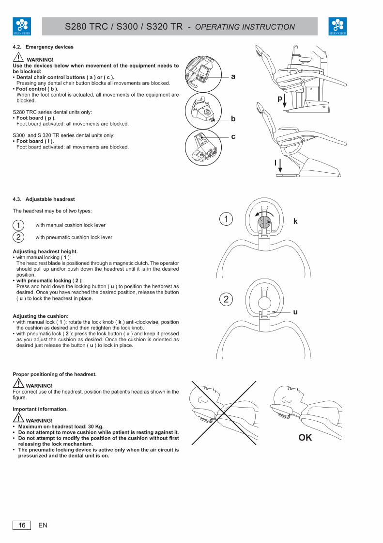
4.2. Emergency devices
WARNING!Use the devices below when movement of the equipment needs to be blocked:• Dental chair control buttons ( a ) or ( c ). Pressinganydentalchairbuttonblocksallmovementsareblocked.• Foot control ( b ). Whenthefootcontrolisactuated,allmovementsoftheequipmentareblocked.
S280TRCseriesdentalunitsonly:• Foot board ( p ). Footboardactivated:allmovementsareblocked.
S300andS320TRseriesdentalunitsonly:• Foot board ( I ). Footboardactivated:allmovementsareblocked.
4.3. Adjustable headrest
Theheadrestmaybeoftwotypes:
1 withmanualcushionlocklever
2 withpneumaticcushionlocklever
Adjusting headrest height.• withmanuallocking (1 ):Theheadrestbladeispositionedthroughamagneticclutch.Theoperatorshouldpullupand/orpushdowntheheadrestuntil it is inthedesiredposition.
• with pneumatic locking (2 ):Pressandholddownthelockingbutton(u)topositiontheheadrestasdesired.Onceyouhavereachedthedesiredposition,releasethebutton(u)tolocktheheadrestinplace.
Adjusting the cushion:•withmanuallock(1 ):rotatethelockknob(k )anti-clockwise,positionthecushionasdesiredandthenretightenthelockknob.
•withpneumaticlock(2 ):pressthelockbutton(u )andkeepitpressedasyouadjustthecushionasdesired.Oncethecushionisorientedasdesiredjustreleasethebutton(u )tolockinplace.
Proper positioning of the headrest.
WARNING!Forcorrectuseoftheheadrest,positionthepatient'sheadasshowninthefigure.
Important information.
WARNING!• Maximum on-headrest load: 30 Kg.• Do not attempt to move cushion while patient is resting against it.• Donotattempttomodifythepositionofthecushionwithoutfirst
releasing the lock mechanism.• The pneumatic locking device is active only when the air circuit is
pressurized and the dental unit is on.
1717
�
�
S280 TRC / S300 / S320 TR - OPERATING INSTRUCTION
17EN
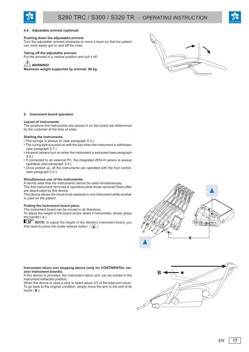
4.4. Adjustable armrest (optional)
Pushing down the adjustable armrest.Turn the adjustable armrest clockwise to move it down so that the patient can more easily get on and off the chair.
Taking off the adjustable armrest.Put the armrest in a vertical position and pull it off.
WARNING!Maximum weight supported by armrest: 68 kg.
5. Instrument board operation
Layout of instruments.The positions the instruments are placed in on the board are determined by the customer at the time of order.
Starting the instruments.• The syringe is always on (see paragraph 5.3.).• The curing light is turned on with the key when the instrument is withdrawn
(see paragraph 5.7.)• Intraoral camera turn on when the instrument is extracted (see paragraph
5.8.).• If connected to an external PC, the integrated ZEN-Xi sensor is always
operative (see paragraph 5.9.).• Once picked up, all the instruments are operated with the foot control.
(see paragraph 5.2.).
Simultaneous use of the instruments.A device sees that the instruments cannot be used simultaneously.The first instrument removed is operative while those removed there after are deactivated by this device.This device allows the chuck to be replaced in one instrument while another is used on the patient.
Putting the instrument board place.The instrument board can be moved in all directions.To adjust the height of the board and/or direct it horizontally, simply grasp the handle ( a ).
NOTE: to adjust the height of the dentist’s instrument board, you first need to press the brake release button ( ).
Instrument return arm stopping device (only for CONTINENTAL ver-sion instrument boards).If this device is provided, the instrument return arm can be locked in the instrument extracted position.When the device is used a click is heard about 2/3 of the total arm travel.To go back to the original condition, simply move the arm to the end of its travel ( B ).
1818
�
�
�
�
S280 TRC / S300 / S320 TR - OPERATING INSTRUCTION
18 EN
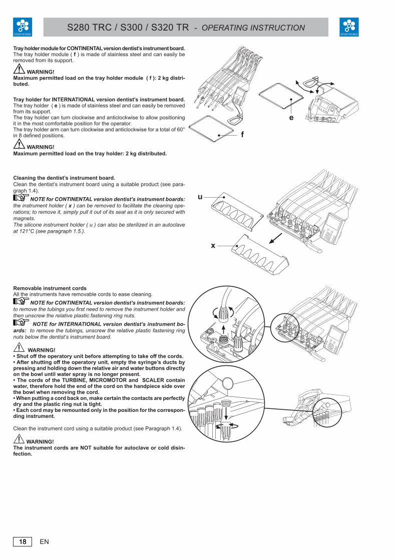
Tray holder module for CONTINENTAL version dentist’s instrument board.The tray holder module ( f ) is made of stainless steel and can easily be removed from its support.
WARNING!Maximum permitted load on the tray holder module ( f ): 2 kg distri-buted.
Tray holder for INTERNATIONAL version dentist’s instrument board.The tray holder ( e ) is made of stainless steel and can easily be removed from its support.The tray holder can turn clockwise and anticlockwise to allow positioning it in the most comfortable position for the operator.The tray holder arm can turn clockwise and anticlockwise for a total of 60° in 8 defined positions.
WARNING!Maximum permitted load on the tray holder: 2 kg distributed.
Cleaning the dentist’s instrument board.Clean the dentist’s instrument board using a suitable product (see para-graph 1.4).
NOTE for CONTINENTAL version dentist’s instrument boards: the instrument holder ( x ) can be removed to facilitate the cleaning ope-rations; to remove it, simply pull it out of its seat as it is only secured with magnets.The silicone instrument holder ( u ) can also be sterilized in an autoclave at 121°C (see paragraph 1.5.).
Removable instrument cordsAll the instruments have removable cords to ease cleaning.
NOTE for CONTINENTAL version dentist’s instrument boards: to remove the tubings you first need to remove the instrument holder and then unscrew the relative plastic fastening ring nuts.
NOTE for INTERNATIONAL version dentist’s instrument bo-ards: to remove the tubings, unscrew the relative plastic fastening ring nuts below the dentist’s instrument board.
WARNING! • Shut off the operatory unit before attempting to take off the cords. • After shutting off the operatory unit, empty the syringe’s ducts by pressing and holding down the relative air and water buttons directly on the bowl until water spray is no longer present. • The cords of the TURBINE, MICROMOTOR and SCALER contain water, therefore hold the end of the cord on the handpiece side over the bowl when removing the cord.• When putting a cord back on, make certain the contacts are perfectly dry and the plastic ring nut is tight. • Each cord may be remounted only in the position for the correspon-ding instrument.
Clean the instrument cord using a suitable product (see Paragraph 1.4).
WARNING! The instrument cords are NOT suitable for autoclave or cold disin-fection.
1919
�
�
S280 TRC / S300 / S320 TR - OPERATING INSTRUCTION
19EN
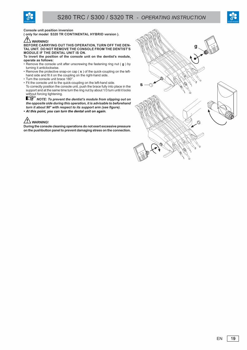
Console unit position inversion( only for model S320 TR CONTINENTAL HYBRID version ).
WARNING!BEFORE CARRYING OUT THIS OPERATION, TURN OFF THE DEN-TAL UNIT. DO NOT REMOVE THE CONSOLE FROM THE DENTIST’S MODULE IF THE DENTAL UNIT IS ON.To invert the position of the console unit on the dentist’s module, operate as follows:• Remove the console unit after unscrewing the fastening ring nut ( g ) by
turning it anticlockwise. • Remove the protective snap-on cap ( s ) of the quick-coupling on the left-
hand side and fit it on the coupling on the right-hand side.• Turn the console unit brace 180°.• Fit the console unit to the quick-coupling on the left-hand side. To correctly position the console unit, push the brace fully into place in the
support and at the same time turn the ring nut by about 1/3 turn until it locks without forcing tightening.
NOTE: To prevent the dentist’s module from slipping out on the opposite side during this operation, it is advisable to beforehand turn it about 90° with respect to its support arm (see figure).
• At this point, you can turn the dental unit on again.
WARNING!During the console cleaning operations do not exert excessive pressure on the pushbutton panel to prevent damaging stress on the connection.
2020
S280 TRC / S300 / S320 TR - OPERATING INSTRUCTION
20 EN
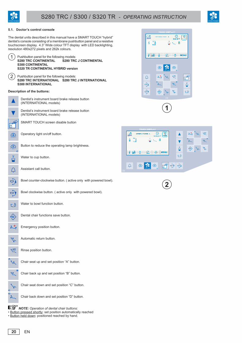
5.1. Doctor’s control console
The dental units described in this manual have a SMART TOUCH “hybrid” dentist’s console consisting of a membrane pushbutton panel and a resistive touchscreen display. 4.3” Wide colour TFT display with LED backlighting, resolution 480x272 pixels and 262k colours.
Pushbutton panel for the following models: S280 TRC CONTINENTAL S280 TRC J CONTINENTAL S300 CONTINENTAL S320 TR CONTINENTAL HYBRID version
Pushbutton panel for the following models: S280 TRC INTERNATIONAL S280 TRC J INTERNATIONAL S300 INTERNATIONAL
Description of the buttons:
Dentist’s instrument board brake release button (INTERNATIONAL models)
Dentist’s instrument board brake release button (INTERNATIONAL models)
SMART TOUCH screen disable button
Operatory light on/off button.
Button to reduce the operating lamp brightness.
Water to cup button.
Assistant call button.
Bowl counter-clockwise button. ( active only with powered bowl).
Bowl clockwise button. ( active only with powered bowl).
Water to bowl function button.
Dental chair functions save button.
Emergency position button.
Automatic return button.
Rinse position button.
Chair seat up and set position “A” button.
Chair back up and set position “B” button.
Chair seat down and set position “C” button.
Chair back down and set position “D” button.
NOTE: Operation of dental chair buttons:• Button pressed shortly: set position automatically reached• Button held down: positioned reached by hand.
2121
S280 TRC / S300 / S320 TR - OPERATING INSTRUCTION
21EN
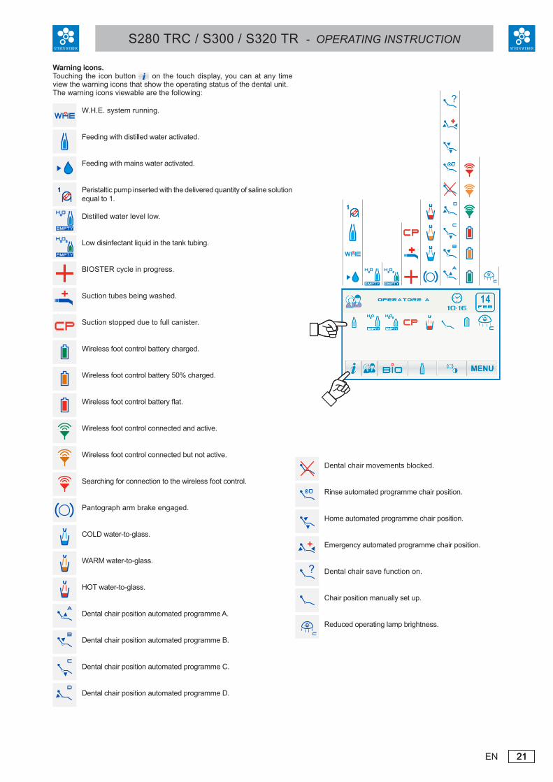
Warning icons.Touching the icon button on the touch display, you can at any time view the warning icons that show the operating status of the dental unit.The warning icons viewable are the following:
W.H.E. system running.
Feeding with distilled water activated.
Feeding with mains water activated.
Peristaltic pump inserted with the delivered quantity of saline solution equal to 1.
Distilled water level low.
Low disinfectant liquid in the tank tubing.
BIOSTER cycle in progress.
Suction tubes being washed.
Suction stopped due to full canister.
Wireless foot control battery charged.
Wireless foot control battery 50% charged.
Wireless foot control battery flat.
Wireless foot control connected and active.
Wireless foot control connected but not active.
Searching for connection to the wireless foot control.
Pantograph arm brake engaged.
COLD water-to-glass.
WARM water-to-glass.
HOT water-to-glass.
Dental chair position automated programme A.
Dental chair position automated programme B.
Dental chair position automated programme C.
Dental chair position automated programme D.
Dental chair movements blocked.
Rinse automated programme chair position.
Home automated programme chair position.
Emergency automated programme chair position.
Dental chair save function on.
Chair position manually set up.
Reduced operating lamp brightness.
2222
�������� ��������
����������������������
����������������������������������
����������������������������������
����������������������
����������
����������
����������
����������
����������
�����������
�����������
S280 TRC / S300 / S320 TR - OPERATING INSTRUCTION
22 EN
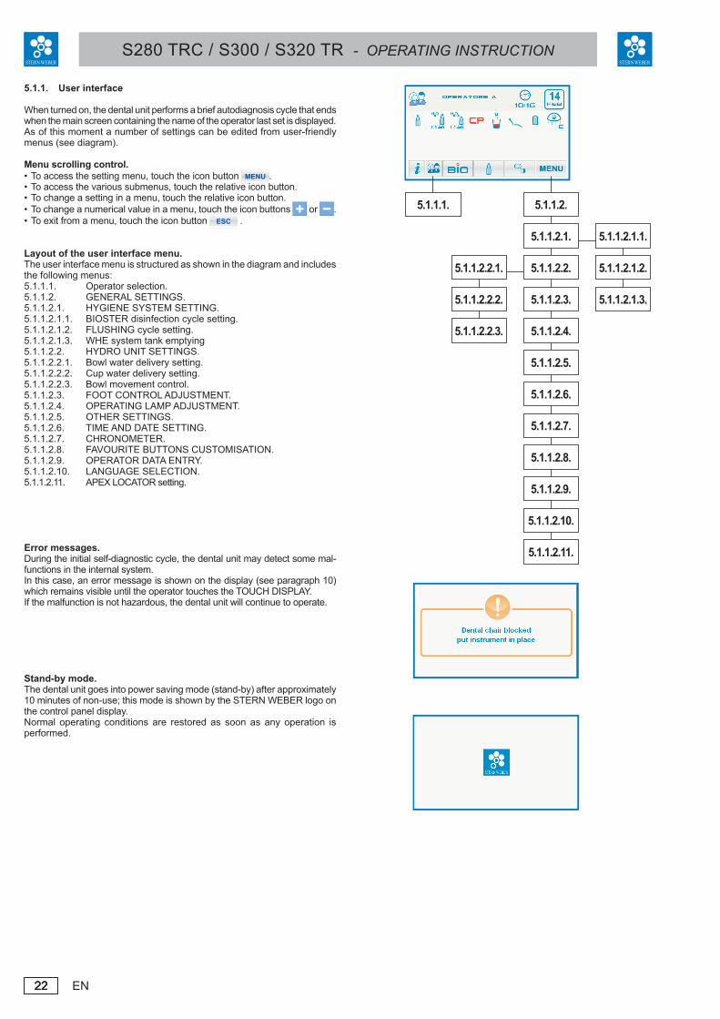
5.1.1. User interface
When turned on, the dental unit performs a brief autodiagnosis cycle that ends when the main screen containing the name of the operator last set is displayed. As of this moment a number of settings can be edited from user-friendly menus (see diagram).
Menu scrolling control.• To access the setting menu, touch the icon button .• To access the various submenus, touch the relative icon button.• To change a setting in a menu, touch the relative icon button.• To change a numerical value in a menu, touch the icon buttons or . • To exit from a menu, touch the icon button .
Layout of the user interface menu.The user interface menu is structured as shown in the diagram and includes the following menus:5.1.1.1. Operator selection. 5.1.1.2. GENERAL SETTINGS. 5.1.1.2.1. HYGIENE SYSTEM SETTING. 5.1.1.2.1.1. BIOSTER disinfection cycle setting. 5.1.1.2.1.2. FLUSHING cycle setting.5.1.1.2.1.3. WHE system tank emptying5.1.1.2.2. HYDRO UNIT SETTINGS. 5.1.1.2.2.1. Bowl water delivery setting.5.1.1.2.2.2. Cup water delivery setting.5.1.1.2.2.3. Bowl movement control.5.1.1.2.3. FOOT CONTROL ADJUSTMENT. 5.1.1.2.4. OPERATING LAMP ADJUSTMENT.5.1.1.2.5. OTHER SETTINGS.5.1.1.2.6. TIME AND DATE SETTING.5.1.1.2.7. CHRONOMETER.5.1.1.2.8. FAVOURITE BUTTONS CUSTOMISATION.5.1.1.2.9. OPERATOR DATA ENTRY.5.1.1.2.10. LANGUAGE SELECTION. 5.1.1.2.11. APEX LOCATOR setting.
Error messages.During the initial self-diagnostic cycle, the dental unit may detect some mal-functions in the internal system.In this case, an error message is shown on the display (see paragraph 10) which remains visible until the operator touches the TOUCH DISPLAY.If the malfunction is not hazardous, the dental unit will continue to operate.
Stand-by mode.The dental unit goes into power saving mode (stand-by) after approximately 10 minutes of non-use; this mode is shown by the STERN WEBER logo on the control panel display.Normal operating conditions are restored as soon as any operation is performed.
2323
S280 TRC / S300 / S320 TR - OPERATING INSTRUCTION
23EN
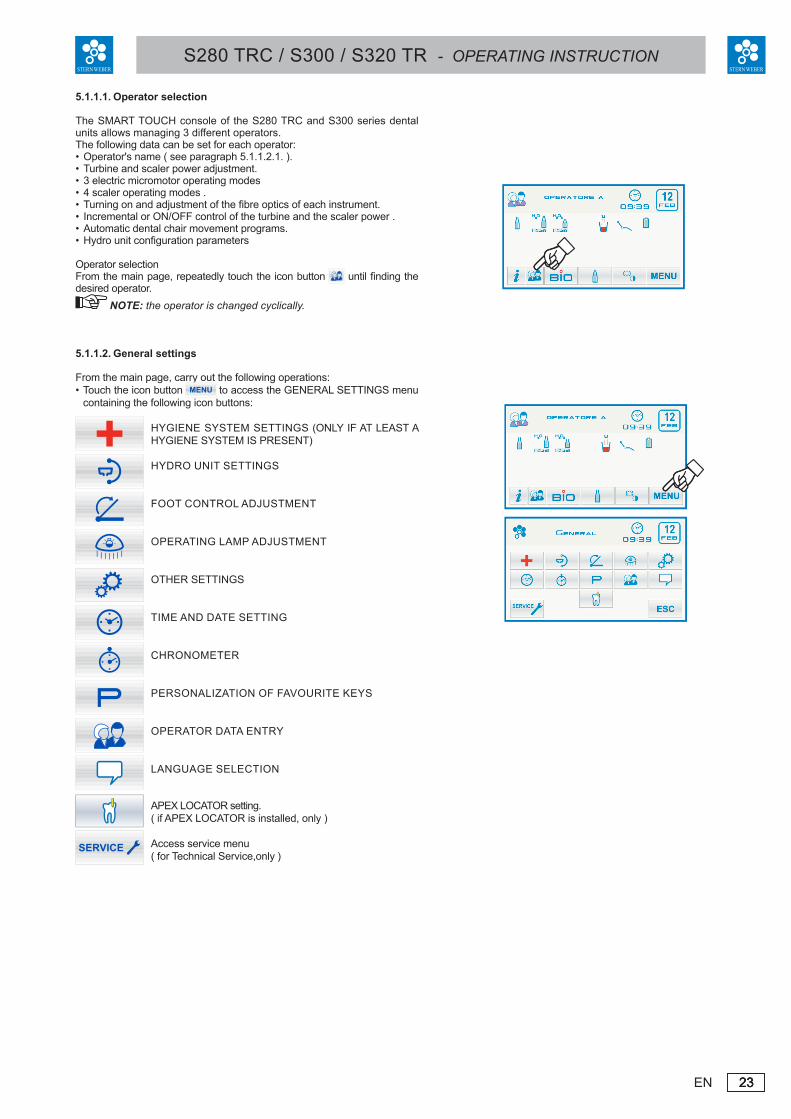
5.1.1.1. Operator selection
The SMART TOUCH console of the S280 TRC and S300 series dental units allows managing 3 different operators.The following data can be set for each operator:• Operator's name ( see paragraph 5.1.1.2.1. ).• Turbine and scaler power adjustment.• 3 electric micromotor operating modes • 4 scaler operating modes .• Turning on and adjustment of the fibre optics of each instrument.• Incremental or ON/OFF control of the turbine and the scaler power .• Automatic dental chair movement programs.• Hydro unit configuration parameters
Operator selectionFrom the main page, repeatedly touch the icon button until finding the desired operator.
NOTE: the operator is changed cyclically.
5.1.1.2. General settings
From the main page, carry out the following operations:• Touch the icon button to access the GENERAL SETTINGS menu
containing the following icon buttons:
HYGIENE SYSTEM SETTINGS (ONLY IF AT LEAST A HYGIENE SYSTEM IS PRESENT)
HYDRO UNIT SETTINGS
FOOT CONTROL ADJUSTMENT
OPERATING LAMP ADJUSTMENT
OTHER SETTINGS
TIME AND DATE SETTING
CHRONOMETER
PERSONALIZATION OF FAVOURITE KEYS
OPERATOR DATA ENTRY
LANGUAGE SELECTION
APEX LOCATOR setting. ( if APEX LOCATOR is installed, only )
Access service menu ( for Technical Service,only )

2424
��
�� � � � �
S280 TRC / S300 / S320 TR - OPERATING INSTRUCTION
24 EN
5.1.1.2.1. Hygiene system settings
NOTE: menu available only if at least a hygiene system is present.
From the GENERAL SETTINGS menu touch the icon button to access the HYGIENE SYSTEM SETTINGS submenu containing the following icon buttons:
BIOSTER disinfection cycle setting (only if the BIOSTER system is present )
Flushing CYCLE SETTING (only if the IWFC system is present)
WHE system tank emptying (only if the WHE system is present)
5.1.1.2.1.1. BIOSTER disinfection cycle setting
This setting is shared by all users.From the HYGIENE SYSTEM SETTINGS menu carry out the following operations:
• Touch the icon button to access the BIOSTER DISINFECTION CYCLE SETTING submenu.
NOTE: this submenu can be entered also by pushing at least for
2 seconds the BIO key on the assistant’s module.
NOTE: This submenu cannot be entered if the disinfectant liquid
tank is low (see paragraph 7.4.), an instrument is removed or the W.H.E.
system is in an error state. An acoustic signal (BEEP) will signal the
impossibility to enter the submenu. • Set the disinfectant dwell time by touching the icon buttons or .
NOTE: the time may range from at least 5 minutes to at most 30 minutes, with 30 second intervals.
WARNING!Recommended permanence time with PEROXY Ag+: 10 minutes.Recommended time 3% hydrogen peroxide (10 volumes) should be left in: 10 minutes.It is strongly unadvisable to let the oxygenated water dwell in the ducts for a contact time of more than 30 minutes.
• Withdraw the instruments to be treated (the corresponding icon will appear on the display):S1: syringe on instrument board.A: instrument in position AB: instrument in position BC: instrument in position CD: instrument in position DS2: syringe on assistant’s board.F: instrument on assistant's board.CA: suction tubes.BC: water to cup duct.
NOTE: pressing the CUP WATER DELIVERY button, you can select/deselect disinfection of the cup water duct.
NOTE: if the flushing system of suction cannulas is present, it is possible to select their flushing by simply putting them into the specially provided connect couplers (see paragraph 7.5.).
• To start the disinfection cycle, touch the icon button (see Paragraph 7.4).
NOTE: the disinfection cycle can be started also by briefly pushing the BIO key on the assistant’s module.
2525
�� � � � �
�
S280 TRC / S300 / S320 TR - OPERATING INSTRUCTION
25EN
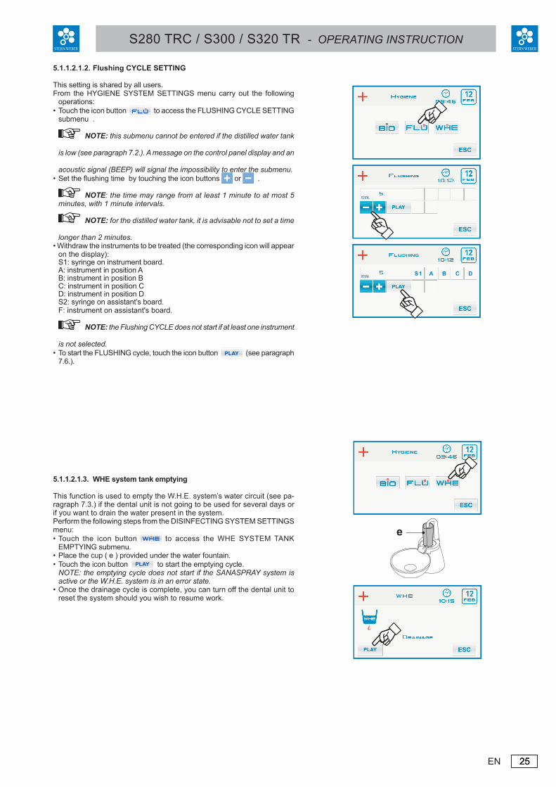
5.1.1.2.1.2. Flushing CYCLE SETTING
This setting is shared by all users.From the HYGIENE SYSTEM SETTINGS menu carry out the following
operations:• Touch the icon button to access the FLUSHING CYCLE SETTING
submenu .
NOTE: this submenu cannot be entered if the distilled water tank
is low (see paragraph 7.2.). A message on the control panel display and an
acoustic signal (BEEP) will signal the impossibility to enter the submenu. • Set the flushing time by touching the icon buttons or .
NOTE: the time may range from at least 1 minute to at most 5 minutes, with 1 minute intervals.
NOTE: for the distilled water tank, it is advisable not to set a time
longer than 2 minutes. • Withdraw the instruments to be treated (the corresponding icon will appear
on the display):S1: syringe on instrument board.A: instrument in position AB: instrument in position BC: instrument in position CD: instrument in position DS2: syringe on assistant’s board.F: instrument on assistant's board.
NOTE: the Flushing CYCLE does not start if at least one instrument
is not selected. • To start the FLUSHING cycle, touch the icon button (see paragraph
7.6.).
5.1.1.2.1.3. WHE system tank emptying
This function is used to empty the W.H.E. system’s water circuit (see pa-ragraph 7.3.) if the dental unit is not going to be used for several days or if you want to drain the water present in the system. Perform the following steps from the DISINFECTING SYSTEM SETTINGS menu: • Touch the icon button to access the WHE SYSTEM TANK
EMPTYING submenu.• Place the cup ( e ) provided under the water fountain.• Touch the icon button to start the emptying cycle.
NOTE: the emptying cycle does not start if the SANASPRAY system is active or the W.H.E. system is in an error state.
• Once the drainage cycle is complete, you can turn off the dental unit to reset the system should you wish to resume work.
2626
S280 TRC / S300 / S320 TR - OPERATING INSTRUCTION
26 EN
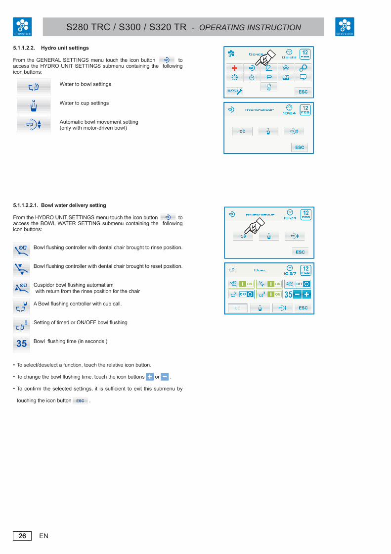
5.1.1.2.2. Hydro unit settings
From the GENERAL SETTINGS menu touch the icon button to access the HYDRO UNIT SETTINGS submenu containing the following icon buttons:
Water to bowl settings
Water to cup settings
Automatic bowl movement setting (only with motor-driven bowl)
5.1.1.2.2.1. Bowl water delivery setting
From the HYDRO UNIT SETTINGS menu touch the icon button to access the BOWL WATER SETTING submenu containing the following icon buttons:
Bowl flushing controller with dental chair brought to rinse position.
Bowl flushing controller with dental chair brought to reset position.
Cuspidor bowl flushing automatism with return from the rinse position for the chair
A Bowl flushing controller with cup call.
Setting of timed or ON/OFF bowl flushing
Bowl flushing time (in seconds )
• To select/deselect a function, touch the relative icon button.
• To change the bowl flushing time, touch the icon buttons or .
• To confirm the selected settings, it is sufficient to exit this submenu by
touching the icon button .
2727
S280 TRC / S300 / S320 TR - OPERATING INSTRUCTION
27EN
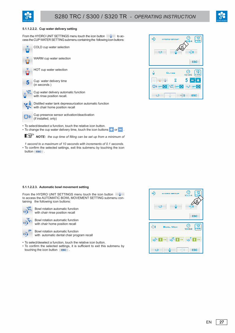
5.1.1.2.2.2. Cup water delivery setting
From the HYDRO UNIT SETTINGS menu touch the icon button to ac-cess the CUP WATER SETTING submenu containing the following icon buttons:
COLD cup water selection
WARM cup water selection
HOT cup water selection
Cup water delivery time (in seconds )
Cup water delivery automatic function with rinse position recall.
Distilled water tank depressurization automatic function with chair home position recall
Cup presence sensor activation/deactivation (if installed, only)
• To select/deselect a function, touch the relative icon button.• To change the cup water delivery time, touch the icon buttons or .
NOTE: the cup time of filling can be set up from a minimum of
1 second to a maximum of 10 seconds with increments of 0.1 seconds. • To confirm the selected settings, exit this submenu by touching the icon
button .
5.1.1.2.2.3. Automatic bowl movement setting
From the HYDRO UNIT SETTINGS menu touch the icon button to access the AUTOMATIC BOWL MOVEMENT SETTING submenu con-taining the following icon buttons:
Bowl rotation automatic function with chair rinse position recall
Bowl rotation automatic function with chair home position recall
Bowl rotation automatic function with automatic dental chair program recall • To select/deselect a function, touch the relative icon button.• To confirm the selected settings, it is sufficient to exit this submenu by
touching the icon button .
2828
S280 TRC / S300 / S320 TR - OPERATING INSTRUCTION
28 EN
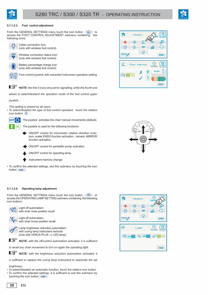
5.1.1.2.3. Foot control adjustment
From the GENERAL SETTINGS menu touch the icon button to access the FOOT CONTROL ADJUSTMENT submenu containing the following icons:
Cable connection icon (only with wireless foot control)
Wireless connection status icon (only with wireless foot control)
Battery percentage charge icon (only with wireless foot control)
Foot control joystick with extracted instrument operation setting
NOTE: the first 3 icons are just for signalling, while the fourth one
allows to select/deselect the operation mode of the foot control upper
joystick.
This setting is shared by all users. • To select/deselect the type of foot control operation, touch the relative
icon button :
The joystick activates the chair manual movements (default).
The joystick is used for the following functions:
ON/OFF control for micromotor rotation direction inver-sion, scaler ENDO function activation , camera MIRROR function activation.
ON/OFF control for peristaltic pump activation.
ON/OFF control for operating lamp.
Instrument memory change.
• To confirm the selected settings, exit this submenu by touching the icon button .
5.1.1.2.4. Operating lamp adjustment
From the GENERAL SETTINGS menu touch the icon button to access the OPERATING LAMP SETTING submenu containing the following icon buttons:
Light off automatism with chair rinse position recall
Light off automatism with chair home position recall
Lamp brightness reduction automatism with curing lamp instrument removal (only with VENUS PLUS –L LED lamp)
NOTE: with the off-control automatism activated, it is sufficient
to recall any chair movement to turn on again the operating light.
NOTE: with the brightness reduction automatism activated, it
is sufficient to replace the curing lamp instrument to reactivate the set
brightness. • To select/deselect an automatic function, touch the relative icon button.• To confirm the selected settings, it is sufficient to exit this submenu by
touching the icon button .
2929
S280 TRC / S300 / S320 TR - OPERATING INSTRUCTION
29EN
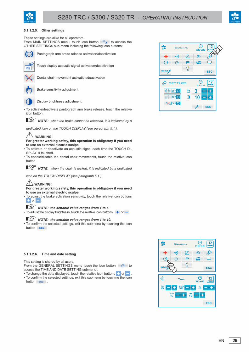
5.1.1.2.5. Other settings
These settings are alike for all operators.From MAIN SETTINGS menu, touch icon button to access the OTHER SETTINGS sub-menu including the following icon buttons:
Pantograph arm brake release activation/deactivation
Touch display acoustic signal activation/deactivation
Dental chair movement activation/deactivation
Brake sensitivity adjustment
Display brightness adjustment
• To activate/deactivate pantograph arm brake release, touch the relative icon button.
NOTE: when the brake cannot be released, it is indicated by a
dedicated icon on the TOUCH DISPLAY (see paragraph 5.1.).
WARNING!For greater working safety, this operation is obligatory if you need to use an external electric scalpel.
• To activate or deactivate an acoustic signal each time the TOUCH DI-SPLAY is touched.
• To enable/disable the dental chair movements, touch the relative icon button.
NOTE: when the chair is locked, it is indicated by a dedicated
icon on the TOUCH DISPLAY (see paragraph 5.1.).
WARNING!For greater working safety, this operation is obligatory if you need to use an external electric scalpel.
• To adjust the brake activation sensitivity, touch the relative icon buttons or .
NOTE: the settable value ranges from 1 to 5.• To adjust the display brightness, touch the relative icon buttons or .
NOTE: the settable value ranges from 1 to 10. • To confirm the selected settings, exit this submenu by touching the icon
button .
5.1.1.2.6. Time and date setting
This setting is shared by all users.From the GENERAL SETTINGS menu touch the icon button to access the TIME AND DATE SETTING submenu .• To change the data displayed, touch the relative icon buttons or .• To confirm the selected settings, exit this submenu by touching the icon
button .
3030
S280 TRC / S300 / S320 TR - OPERATING INSTRUCTION
30 EN
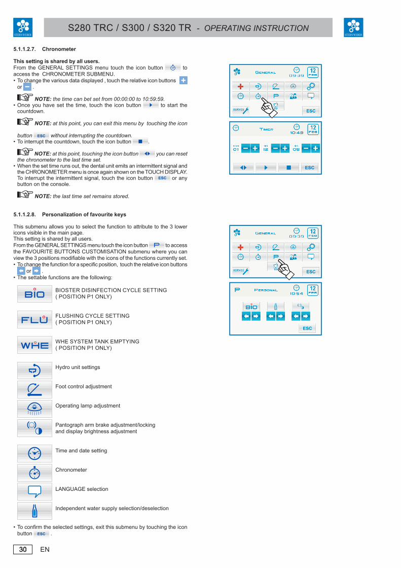
5.1.1.2.7. Chronometer
This setting is shared by all users.From the GENERAL SETTINGS menu touch the icon button to access the CHRONOMETER SUBMENU.• To change the various data displayed , touch the relative icon buttons
or .
NOTE: the time can bet set from 00:00:00 to 10:59:59.• Once you have set the time, touch the icon button to start the
countdown.
NOTE: at this point, you can exit this menu by touching the icon
button without interrupting the countdown.• To interrupt the countdown, touch the icon button .
NOTE: at this point, touching the icon button you can reset the chronometer to the last time set.
• When the set time runs out, the dental unit emits an intermittent signal and the CHRONOMETER menu is once again shown on the TOUCH DISPLAY.To interrupt the intermittent signal, touch the icon button or any button on the console.
NOTE: the last time set remains stored.
5.1.1.2.8. Personalization of favourite keys
This submenu allows you to select the function to attribute to the 3 lower icons visible in the main page.This setting is shared by all users.From the GENERAL SETTINGS menu touch the icon button to access the FAVOURITE BUTTONS CUSTOMISATION submenu where you can view the 3 positions modifiable with the icons of the functions currently set.• To change the function for a specific position, touch the relative icon buttons
or .• The settable functions are the following:
BIOSTER DISINFECTION CYCLE SETTING ( POSITION P1 ONLY)
FLUSHING CYCLE SETTING ( POSITION P1 ONLY)
WHE SYSTEM TANK EMPTYING ( POSITION P1 ONLY)
Hydro unit settings
Foot control adjustment
Operating lamp adjustment
Pantograph arm brake adjustment/locking and display brightness adjustment
Time and date setting
Chronometer
LANGUAGE selection
Independent water supply selection/deselection
• To confirm the selected settings, exit this submenu by touching the icon button .
3131
S280 TRC / S300 / S320 TR - OPERATING INSTRUCTION
31EN
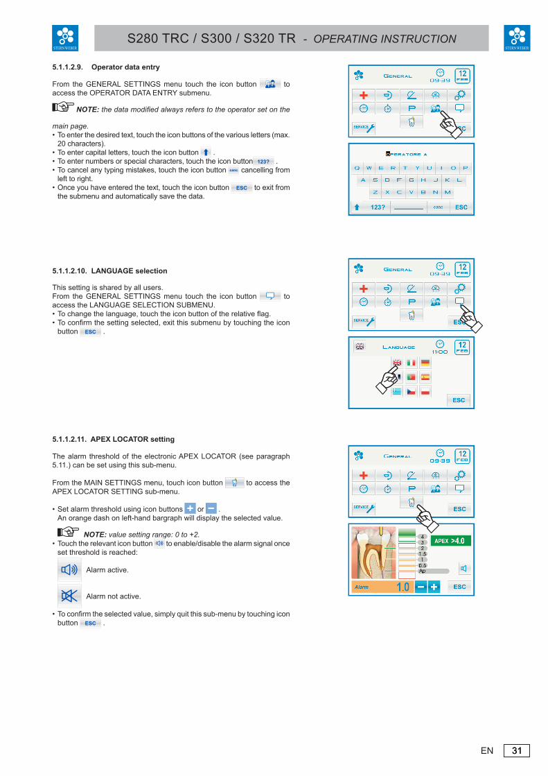
5.1.1.2.9. Operator data entry
From the GENERAL SETTINGS menu touch the icon button to access the OPERATOR DATA ENTRY submenu.
NOTE: the data modified always refers to the operator set on the
main page.• To enter the desired text, touch the icon buttons of the various letters (max.
20 characters).• To enter capital letters, touch the icon button . • To enter numbers or special characters, touch the icon button .• To cancel any typing mistakes, touch the icon button cancelling from
left to right.• Once you have entered the text, touch the icon button to exit from
the submenu and automatically save the data.
5.1.1.2.10. LANGUAGE selection
This setting is shared by all users.From the GENERAL SETTINGS menu touch the icon button to access the LANGUAGE SELECTION SUBMENU.• To change the language, touch the icon button of the relative flag.• To confirm the setting selected, exit this submenu by touching the icon
button .
5.1.1.2.11. APEX LOCATOR setting
The alarm threshold of the electronic APEX LOCATOR (see paragraph 5.11.) can be set using this sub-menu.
From the MAIN SETTINGS menu, touch icon button to access the APEX LOCATOR SETTING sub-menu.
• Set alarm threshold using icon buttons or .An orange dash on left-hand bargraph will display the selected value.
NOTE: value setting range: 0 to +2. • Touch the relevant icon button to enable/disable the alarm signal once
set threshold is reached:
Alarm active.
Alarm not active.
• To confirm the selected value, simply quit this sub-menu by touching icon button .
3232
������
�
�
S280 TRC / S300 / S320 TR - OPERATING INSTRUCTION
32 EN
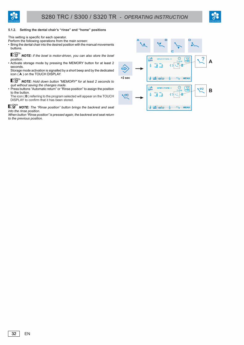
5.1.2. Setting the dental chair’s “rinse” and “home” positions
This setting is specific for each operator.Perform the following operations from the main screen:• Bring the dental chair into the desired position with the manual movements
buttons.
NOTE: if the bowl is motor-driven, you can also store the bowl position.
• Activate storage mode by pressing the MEMORY button for at least 2 seconds.
Storage mode activation is signalled by a short beep and by the dedicated icon ( A ) on the TOUCH DISPLAY.
NOTE: Hold down button "MEMORY" for at least 2 seconds to quit without saving the changes made.
• Press buttons “Automatic return” or “Rinse position” to assign the position to the button.
The icon ( B ) referring to the program selected will appear on the TOUCH DISPLAY to confirm that it has been stored.
NOTE: The “Rinse position” button brings the backrest and seat into the rinse position. When button “Rinse position” is pressed again, the backrest and seat return to the previous position.
3333
������
�
�
�
S280 TRC / S300 / S320 TR - OPERATING INSTRUCTION
33EN
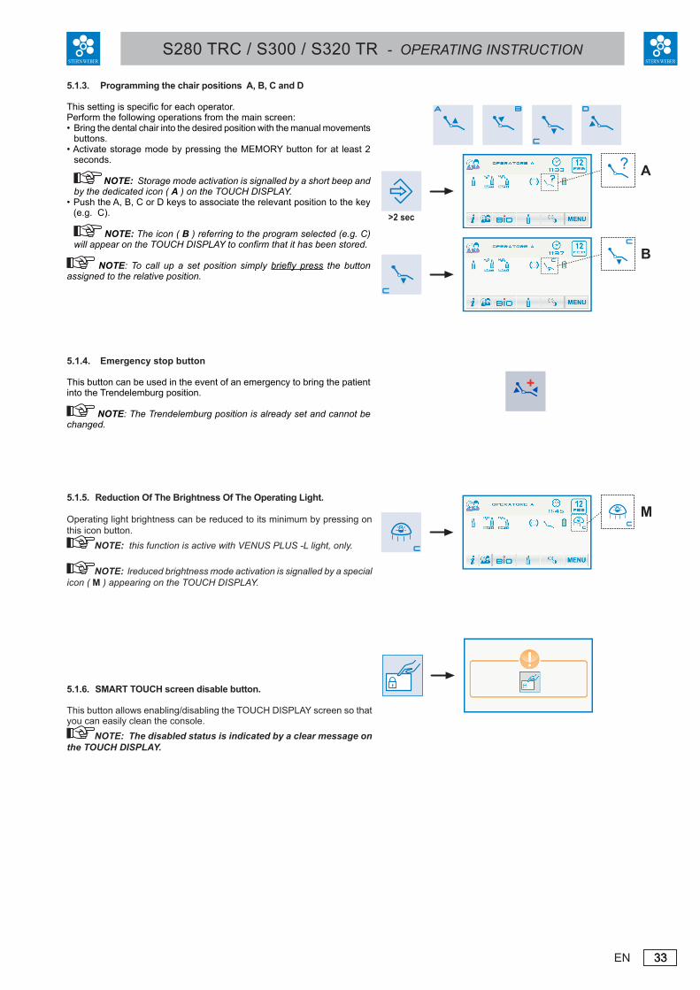
5.1.3. Programming the chair positions A, B, C and D
This setting is specific for each operator.Perform the following operations from the main screen:• Bring the dental chair into the desired position with the manual movements
buttons.• Activate storage mode by pressing the MEMORY button for at least 2
seconds.
NOTE: Storage mode activation is signalled by a short beep and by the dedicated icon ( A ) on the TOUCH DISPLAY.
• Push the A, B, C or D keys to associate the relevant position to the key (e.g. C).
NOTE: The icon ( B ) referring to the program selected (e.g. C) will appear on the TOUCH DISPLAY to confirm that it has been stored.
NOTE: To call up a set position simply briefly press the button assigned to the relative position.
5.1.4. Emergency stop button
This button can be used in the event of an emergency to bring the patient into the Trendelemburg position.
NOTE: The Trendelemburg position is already set and cannot be changed.
5.1.5. Reduction Of The Brightness Of The Operating Light.
Operating light brightness can be reduced to its minimum by pressing on this icon button.
NOTE: this function is active with VENUS PLUS -L light, only.
NOTE: lreduced brightness mode activation is signalled by a special icon ( M ) appearing on the TOUCH DISPLAY.
5.1.6. SMART TOUCH screen disable button.
This button allows enabling/disabling the TOUCH DISPLAY screen so that you can easily clean the console.
NOTE: The disabled status is indicated by a clear message on the TOUCH DISPLAY.
3434
�� �
�
�
�
�
�
���
�
�����
S280 TRC / S300 / S320 TR - OPERATING INSTRUCTION
34 EN
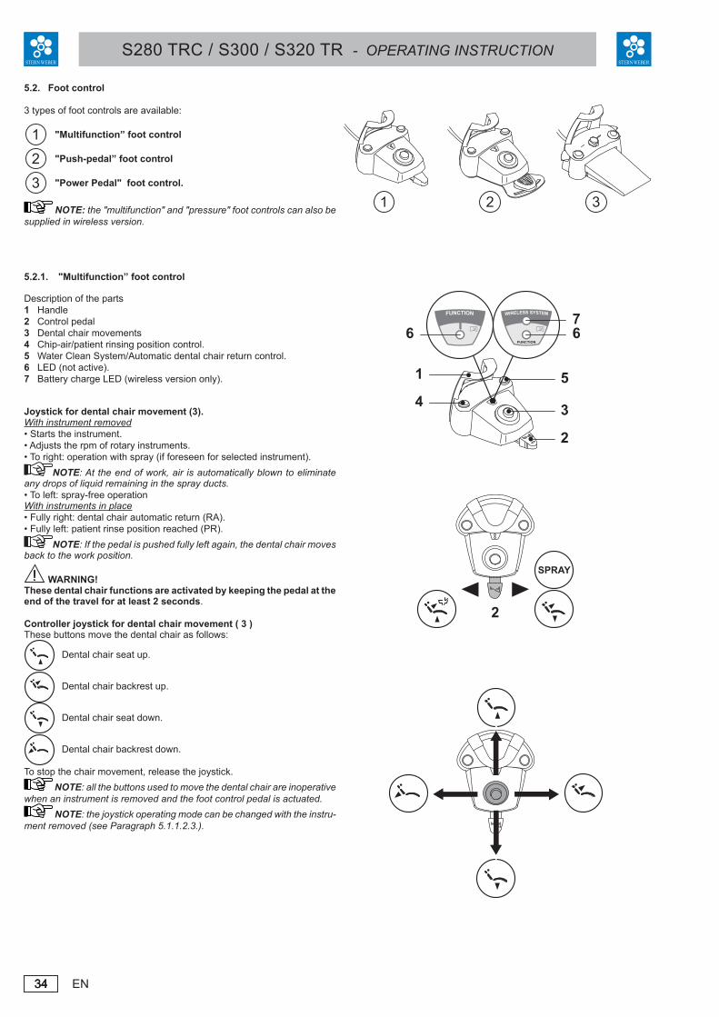
5.2. Foot control
3 types of foot controls are available:
1 "Multifunction” foot control
� "Push-pedal” foot control
� "Power Pedal" foot control.
NOTE: the "multifunction" and "pressure" foot controls can also be supplied in wireless version.
5.2.1. "Multifunction” foot control
Description of the parts1 Handle2 Control pedal3 Dental chair movements4 Chip-air/patient rinsing position control.5 Water Clean System/Automatic dental chair return control.6 LED (not active).7 Battery charge LED (wireless version only).
Joystick for dental chair movement (3).With instrument removed• Starts the instrument.• Adjusts the rpm of rotary instruments.• To right: operation with spray (if foreseen for selected instrument).
NOTE: At the end of work, air is automatically blown to eliminate any drops of liquid remaining in the spray ducts.• To left: spray-free operation With instruments in place• Fully right: dental chair automatic return (RA).• Fully left: patient rinse position reached (PR).
NOTE: If the pedal is pushed fully left again, the dental chair moves back to the work position.
WARNING!These dental chair functions are activated by keeping the pedal at the end of the travel for at least 2 seconds.
Controller joystick for dental chair movement ( 3 )These buttons move the dental chair as follows:
Dental chair seat up.
Dental chair backrest up.
Dental chair seat down.
Dental chair backrest down.
To stop the chair movement, release the joystick. NOTE: all the buttons used to move the dental chair are inoperative
when an instrument is removed and the foot control pedal is actuated. NOTE: the joystick operating mode can be changed with the instru-
ment removed (see Paragraph 5.1.1.2.3.).
3535
�
�
�
�
�
���
�
� �
S280 TRC / S300 / S320 TR - OPERATING INSTRUCTION
35EN
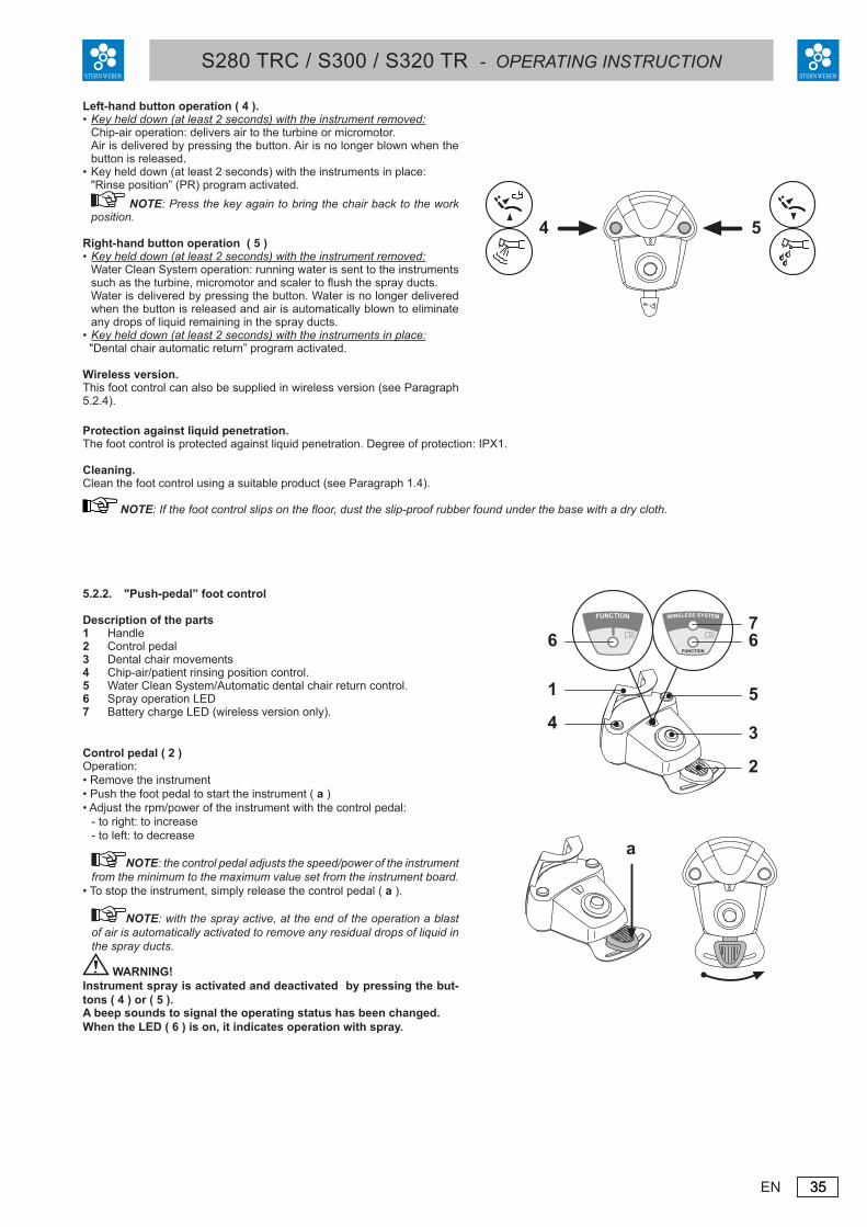
5.2.2. "Push-pedal” foot control
Description of the parts1 Handle2 Control pedal3 Dental chair movements4 Chip-air/patient rinsing position control.5 Water Clean System/Automatic dental chair return control.6 Spray operation LED7 Battery charge LED (wireless version only).
Control pedal ( 2 )Operation:• Remove the instrument• Push the foot pedal to start the instrument ( a )• Adjust the rpm/power of the instrument with the control pedal: - to right: to increase - to left: to decrease
NOTE: the control pedal adjusts the speed/power of the instrument from the minimum to the maximum value set from the instrument board.
• To stop the instrument, simply release the control pedal ( a ).
NOTE: with the spray active, at the end of the operation a blast of air is automatically activated to remove any residual drops of liquid in the spray ducts.
WARNING!Instrument spray is activated and deactivated by pressing the but-tons ( 4 ) or ( 5 ).A beep sounds to signal the operating status has been changed.When the LED ( 6 ) is on, it indicates operation with spray.
Left-hand button operation ( 4 ).• Key held down (at least 2 seconds) with the instrument removed: Chip-air operation: delivers air to the turbine or micromotor. Air is delivered by pressing the button. Air is no longer blown when the
button is released.• Key held down (at least 2 seconds) with the instruments in place: "Rinse position” (PR) program activated. NOTE: Press the key again to bring the chair back to the work
position.
Right-hand button operation ( 5 )• Key held down (at least 2 seconds) with the instrument removed: Water Clean System operation: running water is sent to the instruments
such as the turbine, micromotor and scaler to flush the spray ducts. Water is delivered by pressing the button. Water is no longer delivered
when the button is released and air is automatically blown to eliminate any drops of liquid remaining in the spray ducts.
• Key held down (at least 2 seconds) with the instruments in place: "Dental chair automatic return” program activated.
Wireless version.This foot control can also be supplied in wireless version (see Paragraph 5.2.4).
Protection against liquid penetration.The foot control is protected against liquid penetration. Degree of protection: IPX1.
Cleaning.Clean the foot control using a suitable product (see Paragraph 1.4).
NOTE: If the foot control slips on the floor, dust the slip-proof rubber found under the base with a dry cloth.
3636
�����
��
������
�
S280 TRC / S300 / S320 TR - OPERATING INSTRUCTION
36 EN
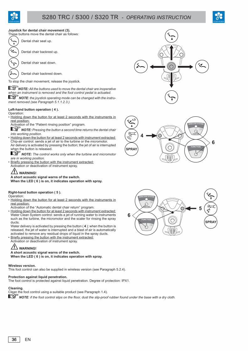
Joystick for dental chair movement (3).These buttons move the dental chair as follows:
Dental chair seat up.
Dental chair backrest up.
Dental chair seat down.
Dental chair backrest down.
To stop the chair movement, release the joystick.
NOTE: All the buttons used to move the dental chair are inoperative when an instrument is removed and the foot control pedal is actuated.
NOTE: the joystick operating mode can be changed with the instru-ment removed (see Paragraph 5.1.1.2.3.).
Left-hand button operation ( 4 ).Operation:• Holding down the button for at least 2 seconds with the instruments in
rest position:Activation of the “Patient rinsing position” program.
NOTE: Pressing the button a second time returns the dental chair into working position.
• Holding down the button for at least 2 seconds with instrument extracted: Chip-air control: sends a jet of air to the turbine or the micromotor. Air delivery is activated by pressing the button; the jet of air is interrupted
when the button is released. NOTE: The control works only when the turbine and micromotor
are in working position.• Briefly pressing the button with the instrument extracted: Activation or deactivation of instrument spray.
WARNING!A short acoustic signal warns of the switch. When the LED ( 6 ) is on, it indicates operation with spray.
Right-hand button operation ( 5 ).Operation:• Holding down the button for at least 2 seconds with the instruments in
rest position:Activation of the “Automatic dental chair return” program.
• Holding down the button for at least 2 seconds with instrument extracted: Water Clean System control: sends a jet of running water to instruments
such as the turbine, the micromotor and the scaler for rinsing the spray ducts.
Water delivery is activated by pressing the button ( 4 ); when the button is released, the jet of water is interrupted and a blast of air is automatically activated to remove any residual drops of liquid in the spray ducts.
• Briefly pressing the button with the instrument extracted: Activation or deactivation of instrument spray.
WARNING!A short acoustic signal warns of the switch. When the LED ( 6 ) is on, it indicates operation with spray.
Wireless version.This foot control can also be supplied in wireless version (see Paragraph 5.2.4).
Protection against liquid penetration.The foot control is protected against liquid penetration. Degree of protection: IPX1.
Cleaning.Clean the foot control using a suitable product (see Paragraph 1.4).
NOTE: if the foot control slips on the floor, dust the slip-proof rubber found under the base with a dry cloth.
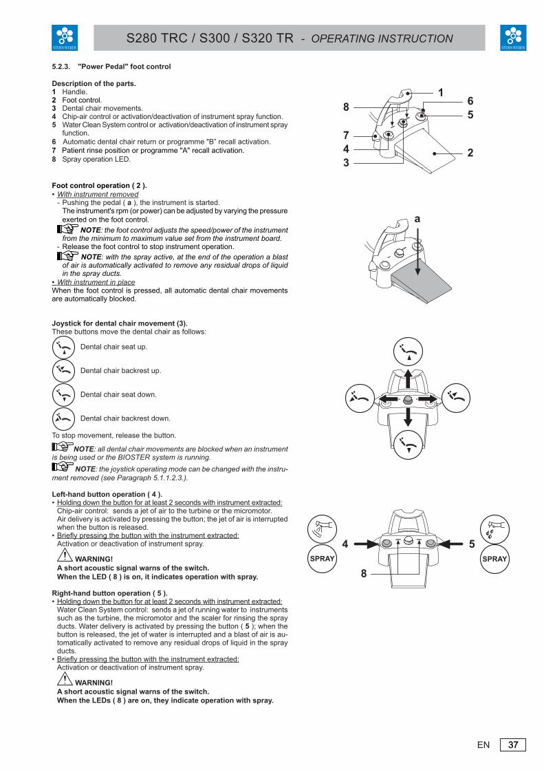
3737
�
�
��
�
���
�
�����
������
� �
S280 TRC / S300 / S320 TR - OPERATING INSTRUCTION
37EN
5.2.3. "Power Pedal" foot control
Description of the parts.1 Handle.2 Foot control.3 Dental chair movements.4 Chip-air control or activation/deactivation of instrument spray function.5 Water Clean System control or activation/deactivation of instrument spray
function.6 Automatic dental chair return or programme "B” recall activation.7 Patient rinse position or programme "A" recall activation.8 Spray operation LED.
Foot control operation ( 2 ).• With instrument removed
- Pushing the pedal ( a ), the instrument is started. The instrument's rpm (or power) can be adjusted by varying the pressure
exerted on the foot control. NOTE: the foot control adjusts the speed/power of the instrument
from the minimum to maximum value set from the instrument board.- Release the foot control to stop instrument operation.
NOTE: with the spray active, at the end of the operation a blast of air is automatically activated to remove any residual drops of liquid in the spray ducts.
• With instrument in placeWhen the foot control is pressed, all automatic dental chair movements are automatically blocked.
Joystick for dental chair movement (3).These buttons move the dental chair as follows:
Dental chair seat up.
Dental chair backrest up.
Dental chair seat down.
Dental chair backrest down.
To stop movement, release the button.
NOTE: all dental chair movements are blocked when an instrument is being used or the BIOSTER system is running.
NOTE: the joystick operating mode can be changed with the instru-ment removed (see Paragraph 5.1.1.2.3.).
Left-hand button operation ( 4 ).• Holding down the button for at least 2 seconds with instrument extracted: Chip-air control: sends a jet of air to the turbine or the micromotor. Air delivery is activated by pressing the button; the jet of air is interrupted
when the button is released.• Briefly pressing the button with the instrument extracted: Activation or deactivation of instrument spray.
WARNING!A short acoustic signal warns of the switch. When the LED ( 8 ) is on, it indicates operation with spray.
Right-hand button operation ( 5 ).• Holding down the button for at least 2 seconds with instrument extracted: Water Clean System control: sends a jet of running water to instruments
such as the turbine, the micromotor and the scaler for rinsing the spray ducts. Water delivery is activated by pressing the button ( 5 ); when the button is released, the jet of water is interrupted and a blast of air is au-tomatically activated to remove any residual drops of liquid in the spray ducts.
• Briefly pressing the button with the instrument extracted: Activation or deactivation of instrument spray.
WARNING!A short acoustic signal warns of the switch. When the LEDs ( 8 ) are on, they indicate operation with spray.
3838
��
S280 TRC / S300 / S320 TR - OPERATING INSTRUCTION
38 EN
Right lever operation ( 6 ). NOTE: the lever functions only with the instruments in their rest
position.For safety reasons, the selected function starts only after the switch has been briefly actuated and then released.• Lever pushed down: "Dental chair automatic return” program activated.• Lever pulled up: Dental chair program “B" start.
Left lever operation ( 7 ). NOTE: the lever functions only with the instruments in their rest
position.For safety reasons, the selected function starts only after the switch has been briefly actuated and then released.• Lever pushed down: "Rinse position” (PR) program activated
NOTE: when the switch is actuated the second time, the dental chair reaches its work position.
• Lever pulled up: Dental chair program “A" start.
Protection against liquid penetration.The foot control is protected against liquid penetration.Degree of protection: IPX1.
Cleaning.Clean the foot control using a suitable product (see Paragraph 1.4).
NOTE: if the foot control slips on the floor, dust the slip-proof rubber found under the base with a dry cloth.
3939
�
�
�
S280 TRC / S300 / S320 TR - OPERATING INSTRUCTION
39EN
5.2.4. Wireless foot control
The "multifunction" and "pressure" foot control can also be supplied in wireless version.The wireless foot control contains a ZIGBEE transmitter module (module certified for Europe, Canada and the USA).
Warnings for use.
WARNING! • Avoid keeping the wireless foot control in proximity of other RF sources, such as wireless LAN cards, other radio devices, home RF de-
vices, microwave ovens. The recommended distance is at least 2 metres in the case of microwave ovens and 1 metre in all other cases.• Even though the electromagnetic field irradiated by the foot control is insignificant, it is advisable NOT to use it in proximity of life sup-
port equipment (e.g. pacemakers or heart stimulators) and hearing aids. Before using any electronic device in health facilities, always ascertain that it is compatible with the other equipment present.
• Exclusively use the dental unit to charge the battery of the WIRELESS foot control.• The internal battery may only be replaced by a qualified technician.
Warnings for first use.It is advisable to fully charge the foot control battery before using it for the first time.
WIRELESS foot control operation.The WIRELESS foot control operates in exactly the same way as the wired version, therefore refer to the paragraphs above paying attention to the specific model used. In addition, the WIRELESS foot control has a specific LED (7) that indicates the battery charge and the communication status with the dental unit.
LED ( 7 ) indications.The colour of the LED indicates the battery charge, while the type of flashing indicates the communication status with the dental unit.
Battery charge:
colour description ( cable disconnected )
description ( cable connected )
GREEN Battery charge (>75%) Battery charged
ORANGE Battery charge (<50%) Battery charging
RED Battery needs charging (<25%) Battery charge error
Off Battery flat Dental unit off or foot control fault
Communication status:
flashing description Slow Connection active in wireless mode
Fast Connection active with charging cable inserted
Double Connection search
On fixed Communication error
NOTE: this information can be shown also on the TOUCH DISPLAY through the specially provided icons ( A ) or ( B ) (see paragraph 5.1.) or in the specially provided control menu of the foot control (see paragraph 5.1.1.2.3.).
Battery characteristics.The WIRELESS foot control is equipped with a rechargeable Lithium-Polymer battery ( Li-Poly, 3.7V, 5200 mAh type Guangzhou Markyn Battery Co. Model 9051109 ).
The battery life is approximately 2 months (estimating 8 hours of consecutive daily operation) with the battery fully charged and fully efficient. The battery efficiency reduces with age. It is estimated that the efficiency is reduced to 60% after 500 complete recharging cycles. Also in this condition, the battery should last about 1 month.
NOTE: When the battery efficiency is so far reduced as to be deemed unsatisfactory to support the daily usage requirements, have it replaced by a qualified technician (original spare part no. 97901336).
WARNING! Do not attempt to replace the battery yourself.
Limited battery warranty.The battery in the foot control is covered by a 6-month warranty from the date of installation.
4040
����
��������
�������
S280 TRC / S300 / S320 TR - OPERATING INSTRUCTION
40 EN
Recharging the battery.When the batteries in the WIRELESS foot control need to be recharged, operate as follows:• Open the protective cap of the connector on the rear of the foot control
and connect the recharging cable.• Connect the other end of the recharging cable to the dental unit (see
figure). At this point, the foot control, while it remains fully operational, will start recharging the battery ( Battery charging warning LED on ).
NOTE: The battery is fully recharged in about 6 hours.
WARNING! Exclusively use the dental unit to charge the battery of the WIRE-LESS foot control.
Natural battery discharge.Should the battery not be used for long periods of time, it may slowly discharge all the same. After long periods of disuse, it is advisable to always fully charge the battery before use.
Maintenance and disposalThe wireless foot control does not contain parts that can be repaired di-rectly by the user. In the event of a malfunction, do not attempt to carry out maintenance operations, but directly contact the manufacturer or his local distributor at the numbers indicated in the warranty certificate. At the end of its lifetime, the battery must be replaced by a specialised technician at a Service Centre.
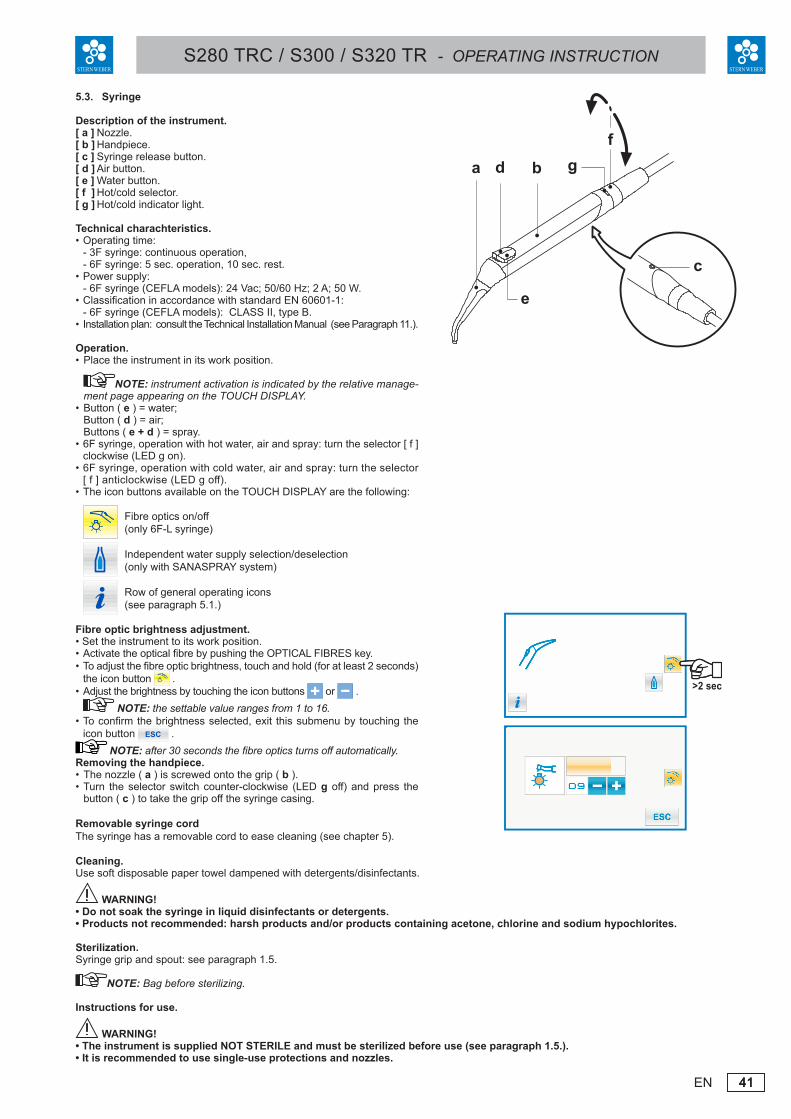
4141
����
�
�
�
������
S280 TRC / S300 / S320 TR - OPERATING INSTRUCTION
41EN
5.3. Syringe
Description of the instrument.[ a ] Nozzle.[ b ] Handpiece.[ c ] Syringe release button.[ d ] Air button.[ e ] Water button.[ f ] Hot/cold selector.[ g ] Hot/cold indicator light.
Technical charachteristics.• Operating time: - 3F syringe: continuous operation, - 6F syringe: 5 sec. operation, 10 sec. rest.• Power supply:
- 6F syringe (CEFLA models): 24 Vac; 50/60 Hz; 2 A; 50 W.• Classification in accordance with standard EN 60601-1:
- 6F syringe (CEFLA models): CLASS II, type B.• Installation plan: consult the Technical Installation Manual (see Paragraph 11.).
Operation.• Place the instrument in its work position.
NOTE: instrument activation is indicated by the relative manage-ment page appearing on the TOUCH DISPLAY.
• Button ( e ) = water; Button ( d ) = air; Buttons ( e + d ) = spray.• 6F syringe, operation with hot water, air and spray: turn the selector [ f ]
clockwise (LED g on).• 6F syringe, operation with cold water, air and spray: turn the selector
[ f ] anticlockwise (LED g off).• The icon buttons available on the TOUCH DISPLAY are the following:
Fibre optics on/off (only 6F-L syringe)
Independent water supply selection/deselection (only with SANASPRAY system)
Row of general operating icons (see paragraph 5.1.)
Fibre optic brightness adjustment.• Set the instrument to its work position. • Activate the optical fibre by pushing the OPTICAL FIBRES key.• To adjust the fibre optic brightness, touch and hold (for at least 2 seconds)
the icon button .• Adjust the brightness by touching the icon buttons or .
NOTE: the settable value ranges from 1 to 16.• To confirm the brightness selected, exit this submenu by touching the
icon button . NOTE: after 30 seconds the fibre optics turns off automatically.
Removing the handpiece.• The nozzle ( a ) is screwed onto the grip ( b ).• Turn the selector switch counter-clockwise (LED g off) and press the
button ( c ) to take the grip off the syringe casing.
Removable syringe cordThe syringe has a removable cord to ease cleaning (see chapter 5).
Cleaning.Use soft disposable paper towel dampened with detergents/disinfectants.
WARNING!• Do not soak the syringe in liquid disinfectants or detergents.• Products not recommended: harsh products and/or products containing acetone, chlorine and sodium hypochlorites.
Sterilization.Syringe grip and spout: see paragraph 1.5.
NOTE: Bag before sterilizing.
Instructions for use.
WARNING!• The instrument is supplied NOT STERILE and must be sterilized before use (see paragraph 1.5.).• It is recommended to use single-use protections and nozzles.
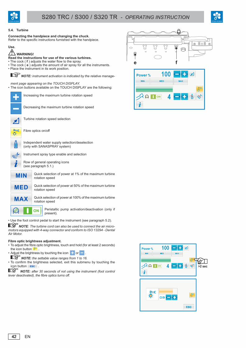
4242
� �
������
S280 TRC / S300 / S320 TR - OPERATING INSTRUCTION
42 EN
5.4. Turbine
Connecting the handpiece and changing the chuck.Refer to the specific instructions furnished with the handpiece.
Use.
WARNING!Read the instructions for use of the various turbines.• The cock ( f ) adjusts the water flow to the spray.• The cock ( e ) adjusts the amount of air spray for all the instruments.• Place the instrument in its work position.
NOTE: instrument activation is indicated by the relative manage-
ment page appearing on the TOUCH DISPLAY. • The icon buttons available on the TOUCH DISPLAY are the following:
Increasing the maximum turbine rotation speed
Decreasing the maximum turbine rotation speed
Turbine rotation speed selection
Fibre optics on/off
Independent water supply selection/deselection (only with SANASPRAY system)
Instrument spray type enable and selection
Row of general operating icons (see paragraph 5.1.)
Quick selection of power at 1% of the maximum turbine rotation speed
Quick selection of power at 50% of the maximum turbine rotation speed
Quick selection of power at 100% of the maximum turbine rotation speed
Peristaltic pump activation/deactivation (only if present).
• Use the foot control pedal to start the instrument (see paragraph 5.2).
NOTE: The turbine cord can also be used to connect the air micro-motors equipped with 4-way connector and conform to ISO 13294 - Dental Air Motor.
Fibre optic brightness adjustment.• To adjust the fibre optic brightness, touch and hold (for at least 2 seconds)
the icon button .• Adjust the brightness by touching the icon or .
NOTE: the settable value ranges from 1 to 16.• To confirm the brightness selected, exit this submenu by touching the
icon button . NOTE: after 30 seconds of not using the instrument (foot control
lever deactivated), the fibre optics turns off.
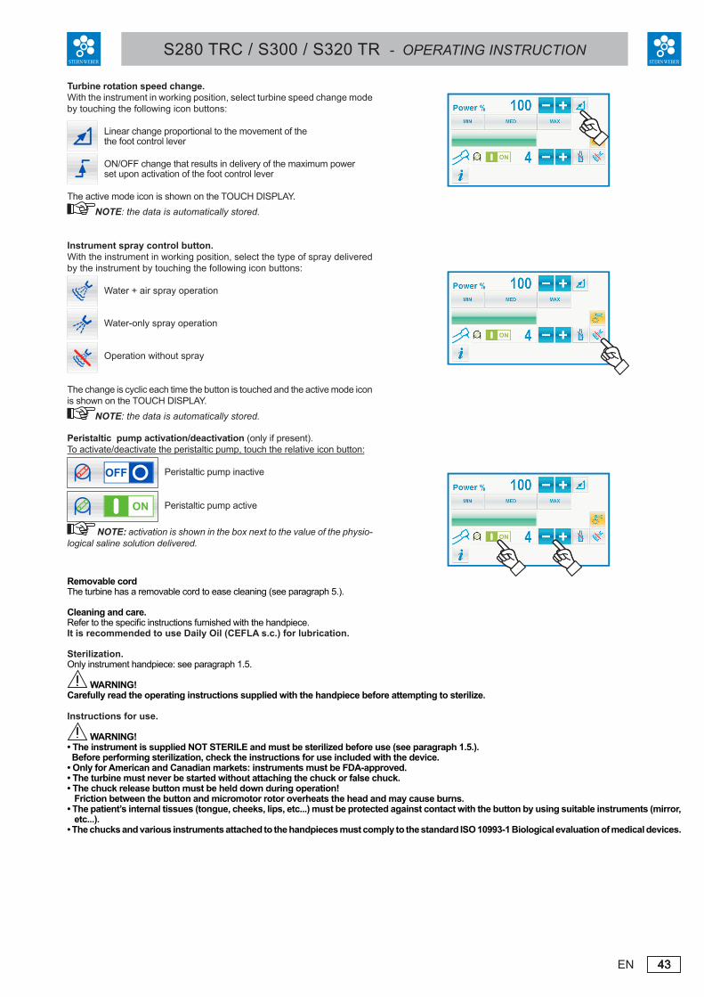
4343
S280 TRC / S300 / S320 TR - OPERATING INSTRUCTION
43EN
Removable cordThe turbine has a removable cord to ease cleaning (see paragraph 5.).
Cleaning and care.Refer to the specific instructions furnished with the handpiece.It is recommended to use Daily Oil (CEFLA s.c.) for lubrication.
Sterilization.Only instrument handpiece: see paragraph 1.5.
WARNING!Carefully read the operating instructions supplied with the handpiece before attempting to sterilize.
Instructions for use.
WARNING!• The instrument is supplied NOT STERILE and must be sterilized before use (see paragraph 1.5.). Before performing sterilization, check the instructions for use included with the device.• Only for American and Canadian markets: instruments must be FDA-approved.• The turbine must never be started without attaching the chuck or false chuck.• The chuck release button must be held down during operation! Friction between the button and micromotor rotor overheats the head and may cause burns.• The patient’s internal tissues (tongue, cheeks, lips, etc...) must be protected against contact with the button by using suitable instruments (mirror,
etc...).• The chucks and various instruments attached to the handpieces must comply to the standard ISO 10993-1 Biological evaluation of medical devices.
Turbine rotation speed change.With the instrument in working position, select turbine speed change mode by touching the following icon buttons:
Linear change proportional to the movement of the the foot control lever
ON/OFF change that results in delivery of the maximum power set upon activation of the foot control lever
The active mode icon is shown on the TOUCH DISPLAY. NOTE: the data is automatically stored.
Instrument spray control button.With the instrument in working position, select the type of spray delivered by the instrument by touching the following icon buttons:
Water + air spray operation
Water-only spray operation
Operation without spray
The change is cyclic each time the button is touched and the active mode icon is shown on the TOUCH DISPLAY.
NOTE: the data is automatically stored.
Peristaltic pump activation/deactivation (only if present).To activate/deactivate the peristaltic pump, touch the relative icon button:
Peristaltic pump inactive
Peristaltic pump active
NOTE: activation is shown in the box next to the value of the physio-
logical saline solution delivered.
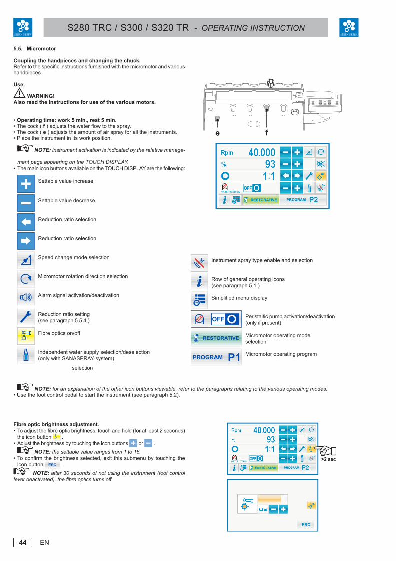
4444
� �
������
S280 TRC / S300 / S320 TR - OPERATING INSTRUCTION
44 EN
5.5. Micromotor
Coupling the handpieces and changing the chuck. Refer to the specific instructions furnished with the micromotor and various handpieces.
Use.
WARNING!Also read the instructions for use of the various motors.
• Operating time: work 5 min., rest 5 min.• The cock ( f ) adjusts the water flow to the spray.• The cock ( e ) adjusts the amount of air spray for all the instruments.• Place the instrument in its work position.
NOTE: instrument activation is indicated by the relative manage-
ment page appearing on the TOUCH DISPLAY. • The main icon buttons available on the TOUCH DISPLAY are the following:
Settable value increase
Settable value decrease
Reduction ratio selection
Reduction ratio selection
Speed change mode selection
Micromotor rotation direction selection
Alarm signal activation/deactivation
Reduction ratio setting (see paragraph 5.5.4.)
Fibre optics on/off
Independent water supply selection/deselection (only with SANASPRAY system)
Fibre optic brightness adjustment.• To adjust the fibre optic brightness, touch and hold (for at least 2 seconds)
the icon button .• Adjust the brightness by touching the icon buttons or .
NOTE: the settable value ranges from 1 to 16.• To confirm the brightness selected, exit this submenu by touching the
icon button . NOTE: after 30 seconds of not using the instrument (foot control
lever deactivated), the fibre optics turns off.
Instrument spray type enable and selection
Row of general operating icons
(see paragraph 5.1.)
Simplified menu display
Peristaltic pump activation/deactivation (only if present)
Micromotor operating mode selection
Micromotor operating program
selection
NOTE: for an explanation of the other icon buttons viewable, refer to the paragraphs relating to the various operating modes.• Use the foot control pedal to start the instrument (see paragraph 5.2).
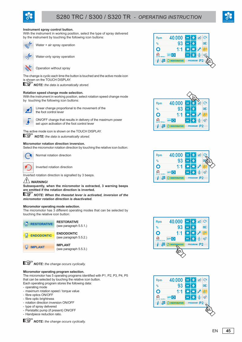
4545
S280 TRC / S300 / S320 TR - OPERATING INSTRUCTION
45EN
Instrument spray control button.With the instrument in working position, select the type of spray delivered by the instrument by touching the following icon buttons:
Water + air spray operation
Water-only spray operation
Operation without spray The change is cyclic each time the button is touched and the active mode icon is shown on the TOUCH DISPLAY.
NOTE: the data is automatically stored.
Rotation speed change mode selection.With the instrument in working position, select rotation speed change mode by touching the following icon buttons:
Linear change proportional to the movement of the the foot control lever
ON/OFF change that results in delivery of the maximum power set upon activation of the foot control lever
The active mode icon is shown on the TOUCH DISPLAY. NOTE: the data is automatically stored.
Micromotor rotation direction inversion.Select the micromotor rotation direction by touching the relative icon button:
Normal rotation direction
Inverted rotation direction
Inverted rotation direction is signalled by 3 beeps.
WARNING!Subsequently, when the micromotor is extracted, 3 warning beeps are emitted if the rotation direction is inverted.
NOTE: When the rheostat lever is activated, inversion of the micromotor rotation direction is deactivated.
Micromotor operating mode selection.The micromotor has 3 different operating modes that can be selected by touching the relative icon button:
RESTORATIVE (see paragraph 5.5.1.)
ENDODONTIC (see paragraph 5.5.2.)
IMPLANT (see paragraph 5.5.3.)
NOTE: the change occurs cyclically.
Micromotor operating program selection.The micromotor has 5 operating programs identified with P1, P2, P3, P4, P5 that can be selected by touching the relative icon button.Each operating program stores the following data:- operating mode- maximum rotation speed / torque value- fibre optics ON/OFF- fibre optic brightness- rotation direction inversion ON/OFF- type of spray delivered- Peristaltic pump (if present) ON/OFF- Handpiece reduction ratio.
NOTE: the change occurs cyclically.
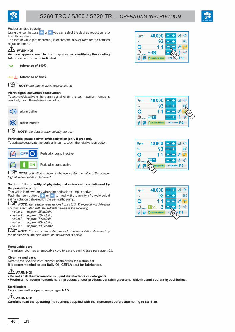
4646
S280 TRC / S300 / S320 TR - OPERATING INSTRUCTION
46 EN
Reduction ratio selection.Using the icon buttons or you can select the desired reduction ratio from those stored.The torque value (set or current) is expressed in % or Ncm for the certified reduction gears.
WARNING!An icon appears next to the torque value identifying the reading tolerance on the value indicated:
tolerance of ±10%
tolerance of ±20%.
NOTE: the data is automatically stored.
Alarm signal activation/deactivation.To activate/deactivate the alarm signal when the set maximum torque is reached, touch the relative icon button:
alarm active
alarm inactive
NOTE: the data is automatically stored.
Peristaltic pump activation/deactivation (only if present).To activate/deactivate the peristaltic pump, touch the relative icon button:
Peristaltic pump inactive
Peristaltic pump active
NOTE: activation is shown in the box next to the value of the physio-
logical saline solution delivered.
Setting of the quantity of physiological saline solution delivered by the peristaltic pump. This value is shown only when the peristaltic pump is active.Push the icon buttons or to modify the quantity of physiological saline solution delivered by the peristaltic pump.
NOTE: the settable value ranges from 1 to 5. The quantity of delivered solution associated with the settable values is the following:
- value 1: approx. 35 cc/min,- value 2: approx. 50 cc/min,- value 3: approx. 70 cc/min,- value 4: approx. 90 cc/min,- value 5: approx. 100 cc/min.
NOTE: You can change the amount of saline solution delivered by the peristaltic pump also when the instrument is active.
Removable cordThe micromotor has a removable cord to ease cleaning (see paragraph 5.).
Cleaning and care.Refer to the specific instructions furnished with the instrument.It is recommended to use Daily Oil (CEFLA s.c.) for lubrication.
WARNING!• Do not soak the micromotor in liquid disinfectants or detergents.• Products not recommended: harsh products and/or products containing acetone, chlorine and sodium hypochlorites.
Sterilization.Only instrument handpiece: see paragraph 1.5.
WARNING!Carefully read the operating instructions supplied with the instrument before attempting to sterilize.
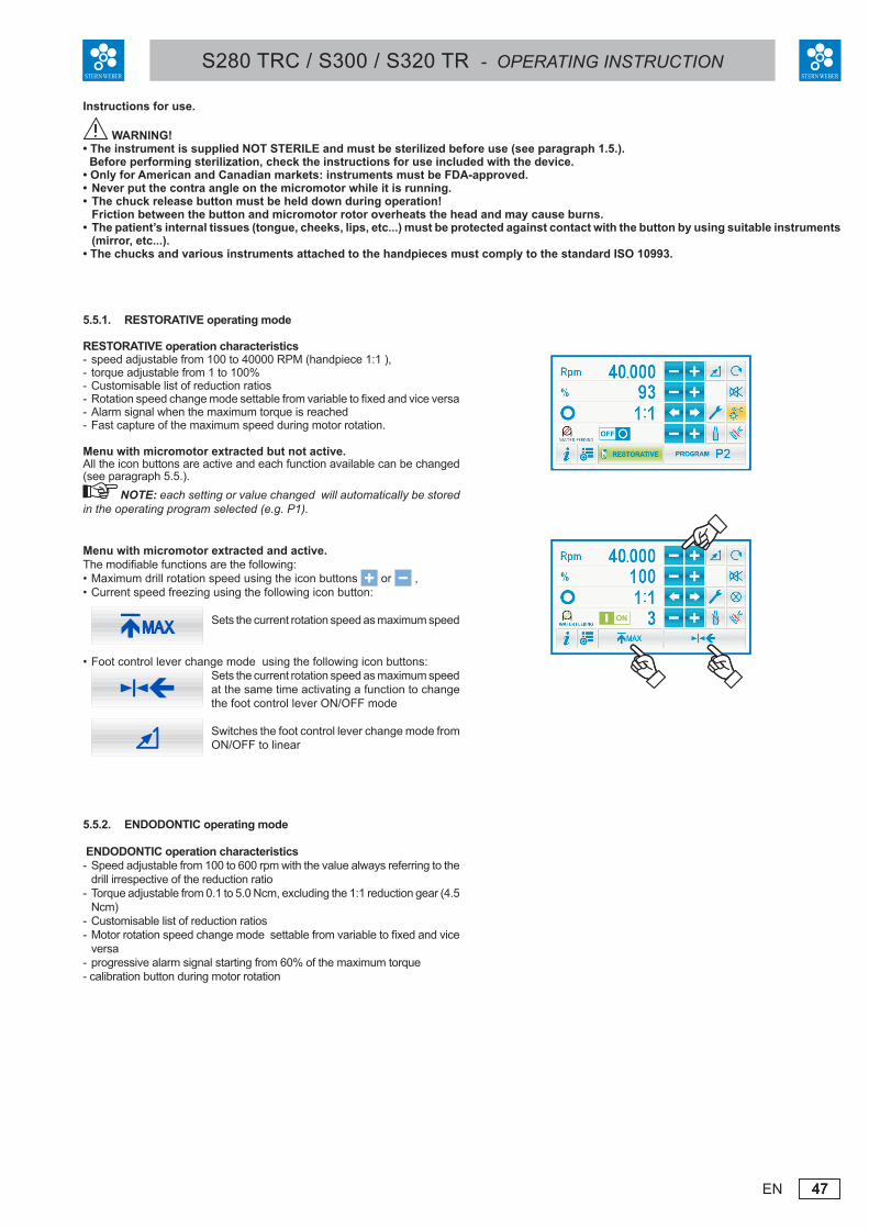
4747
S280 TRC / S300 / S320 TR - OPERATING INSTRUCTION
47EN
5.5.1. RESTORATIVE operating mode
RESTORATIVE operation characteristics- speed adjustable from 100 to 40000 RPM (handpiece 1:1 ),- torque adjustable from 1 to 100%- Customisable list of reduction ratios- Rotation speed change mode settable from variable to fixed and vice versa - Alarm signal when the maximum torque is reached- Fast capture of the maximum speed during motor rotation.
Menu with micromotor extracted but not active.All the icon buttons are active and each function available can be changed (see paragraph 5.5.).
NOTE: each setting or value changed will automatically be stored in the operating program selected (e.g. P1).
Menu with micromotor extracted and active.The modifiable functions are the following:• Maximum drill rotation speed using the icon buttons or ,• Current speed freezing using the following icon button:
Sets the current rotation speed as maximum speed
• Foot control lever change mode using the following icon buttons: Sets the current rotation speed as maximum speed
at the same time activating a function to change the foot control lever ON/OFF mode
Switches the foot control lever change mode from
ON/OFF to linear
5.5.2. ENDODONTIC operating mode
ENDODONTIC operation characteristics - Speed adjustable from 100 to 600 rpm with the value always referring to the
drill irrespective of the reduction ratio- Torque adjustable from 0.1 to 5.0 Ncm, excluding the 1:1 reduction gear (4.5
Ncm)- Customisable list of reduction ratios- Motor rotation speed change mode settable from variable to fixed and vice
versa - progressive alarm signal starting from 60% of the maximum torque- calibration button during motor rotation
Instructions for use.
WARNING!• The instrument is supplied NOT STERILE and must be sterilized before use (see paragraph 1.5.). Before performing sterilization, check the instructions for use included with the device.• Only for American and Canadian markets: instruments must be FDA-approved.• Never put the contra angle on the micromotor while it is running.• The chuck release button must be held down during operation! Friction between the button and micromotor rotor overheats the head and may cause burns.• The patient’s internal tissues (tongue, cheeks, lips, etc...) must be protected against contact with the button by using suitable instruments
(mirror, etc...).• The chucks and various instruments attached to the handpieces must comply to the standard ISO 10993.
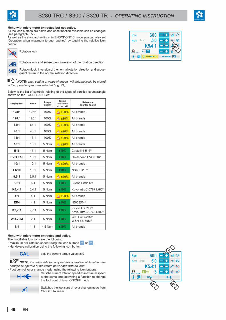
4848
S280 TRC / S300 / S320 TR - OPERATING INSTRUCTION
48 EN
Menu with micromotor extracted but not active.All the icon buttons are active and each function available can be changed (see paragraph 5.5.).As well as the standard settings, in ENDODONTIC mode you can also set “Operation when maximum torque reached” by touching the relative icon button:
Rotation lock
Rotation lock and subsequent inversion of the rotation direction
Rotation lock, inversion of the normal rotation direction and subse-quent return to the normal rotation direction
NOTE: each setting or value changed will automatically be stored in the operating program selected (e.g. P1).
Below is the list of symbols relating to the types of certified counterangle shown on the TOUCH DISPLAY:
Display text Ratio Torque display
Torque tolerance at the drill
Reference counter-angles
128:1 128:1 100% ±20% All brands
120:1 120:1 100% ±20% All brands
64:1 64:1 100% ±20% All brands
40:1 40:1 100% ±20% All brands
18:1 18:1 100% ±20% All brands
16:1 16:1 5 Ncm ±20% All brands
E16 16:1 5 Ncm ±10% Castellini E16®
EVO E16 16:1 5 Ncm ±10% Goldspeed EVO E16®
10:1 10:1 5 Ncm ±20% All brands
ER10 10:1 5 Ncm ±10% NSK ER10®
9,5:1 9,5:1 5 Ncm ±20% All brands
S6:1 6:1 5 Ncm ±10% Sirona Endo 6:1
K5,4:1 5,4:1 5 Ncm ±10% Kavo IntraC 0767 LHC®
4:1 4:1 5 Ncm ±20% All brands
ER4 4:1 5 Ncm ±10% NSK ER4®
K2,7:1 2,7:1 5 Ncm ±10% Kavo LUX 7LP® Kavo IntraC 0768 LHC®
WD-79M 2:1 5 Ncm ±10% W&H WD-79M®
W&H EB-79M®
1:1 1:1 4,5 Ncm ±10% All brands
Menu with micromotor extracted and active.The modifiable functions are the following:• Maximum drill rotation speed using the icon buttons or ,• Handpiece calibration using the following icon button:
sets the current torque value as 0
NOTE: it is advisable to carry out this operation while letting the handpiece operate at maximum power and with no load.
• Foot control lever change mode using the following icon buttons: Sets the current rotation speed as maximum speed
at the same time activating a function to change the foot control lever ON/OFF mode
Switches the foot control lever change mode from
ON/OFF to linear
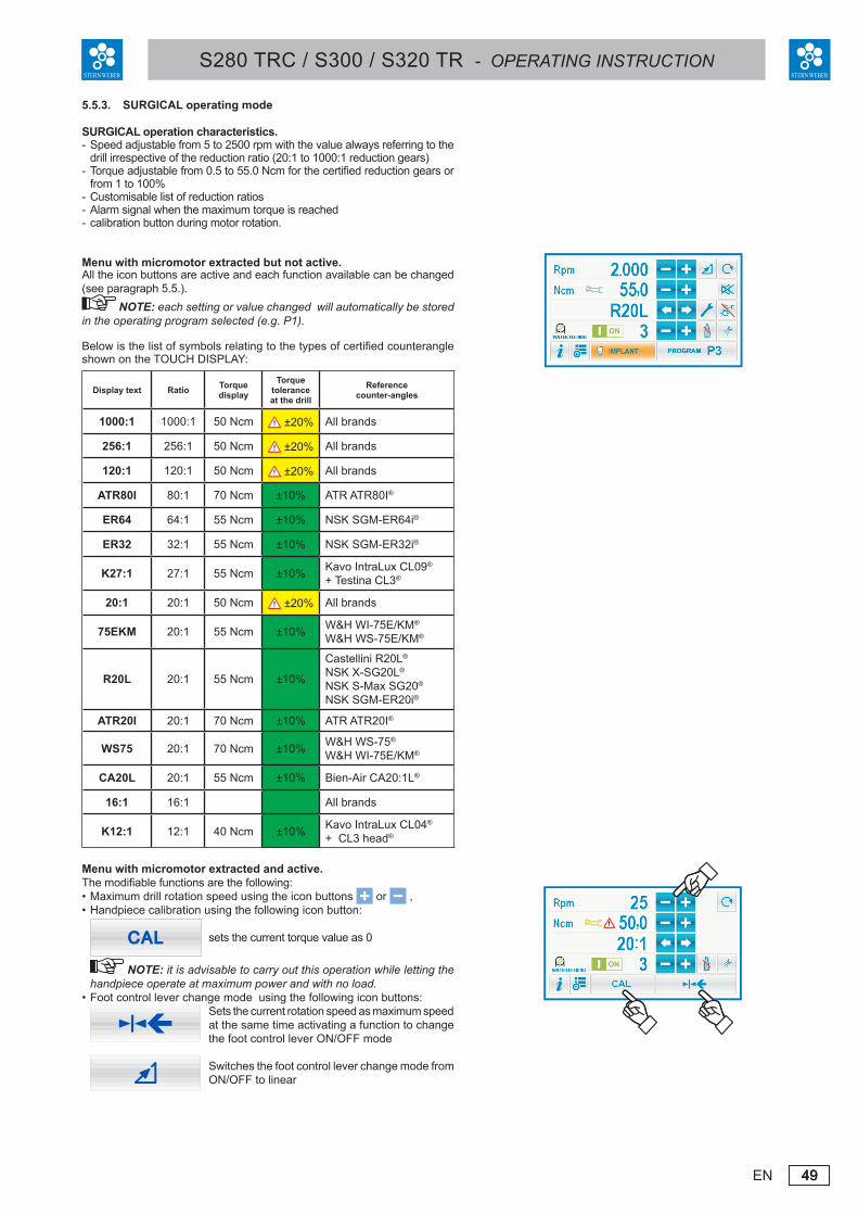
4949
S280 TRC / S300 / S320 TR - OPERATING INSTRUCTION
49EN
5.5.3. SURGICAL operating mode
SURGICAL operation characteristics.- Speed adjustable from 5 to 2500 rpm with the value always referring to the
drill irrespective of the reduction ratio (20:1 to 1000:1 reduction gears)- Torque adjustable from 0.5 to 55.0 Ncm for the certified reduction gears or
from 1 to 100%- Customisable list of reduction ratios- Alarm signal when the maximum torque is reached- calibration button during motor rotation.
Menu with micromotor extracted but not active.All the icon buttons are active and each function available can be changed (see paragraph 5.5.).
NOTE: each setting or value changed will automatically be stored in the operating program selected (e.g. P1).
Below is the list of symbols relating to the types of certified counterangle shown on the TOUCH DISPLAY:
Display text Ratio Torque display
Torque toleranceat the drill
Reference counter-angles
1000:1 1000:1 50 Ncm ±20% All brands
256:1 256:1 50 Ncm ±20% All brands
120:1 120:1 50 Ncm ±20% All brands
ATR80I 80:1 70 Ncm ±10% ATR ATR80I®
ER64 64:1 55 Ncm ±10% NSK SGM-ER64i®
ER32 32:1 55 Ncm ±10% NSK SGM-ER32i®
K27:1 27:1 55 Ncm ±10% Kavo IntraLux CL09®
+ Testina CL3®
20:1 20:1 50 Ncm ±20% All brands
75EKM 20:1 55 Ncm ±10% W&H WI-75E/KM® W&H WS-75E/KM®
R20L 20:1 55 Ncm ±10%
Castellini R20L® NSK X-SG20L® NSK S-Max SG20® NSK SGM-ER20i®
ATR20I 20:1 70 Ncm ±10% ATR ATR20I®
WS75 20:1 70 Ncm ±10% W&H WS-75® W&H WI-75E/KM®
CA20L 20:1 55 Ncm ±10% Bien-Air CA20:1L®
16:1 16:1 All brands
K12:1 12:1 40 Ncm ±10% Kavo IntraLux CL04® + CL3 head®
Menu with micromotor extracted and active.The modifiable functions are the following:• Maximum drill rotation speed using the icon buttons or ,• Handpiece calibration using the following icon button:
sets the current torque value as 0
NOTE: it is advisable to carry out this operation while letting the handpiece operate at maximum power and with no load.
• Foot control lever change mode using the following icon buttons: Sets the current rotation speed as maximum speed
at the same time activating a function to change the foot control lever ON/OFF mode
Switches the foot control lever change mode from
ON/OFF to linear
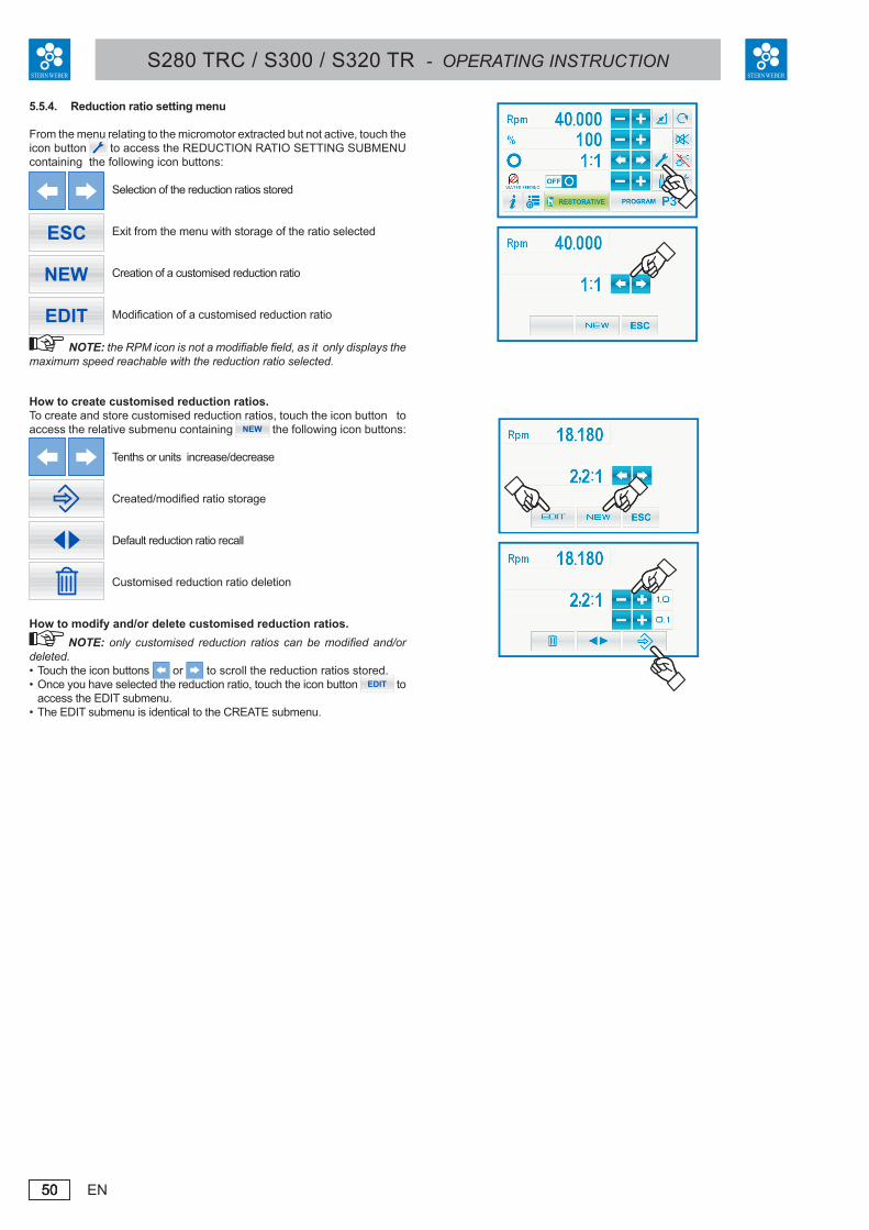
5050
S280 TRC / S300 / S320 TR - OPERATING INSTRUCTION
50 EN
5.5.4. Reduction ratio setting menu
From the menu relating to the micromotor extracted but not active, touch the icon button to access the REDUCTION RATIO SETTING SUBMENU containing the following icon buttons:
Selection of the reduction ratios stored
Exit from the menu with storage of the ratio selected
Creation of a customised reduction ratio
Modification of a customised reduction ratio
NOTE: the RPM icon is not a modifiable field, as it only displays the maximum speed reachable with the reduction ratio selected.
How to create customised reduction ratios.To create and store customised reduction ratios, touch the icon button to access the relative submenu containing the following icon buttons:
Tenths or units increase/decrease
Created/modified ratio storage
Default reduction ratio recall
Customised reduction ratio deletion
How to modify and/or delete customised reduction ratios. NOTE: only customised reduction ratios can be modified and/or
deleted.• Touch the icon buttons or to scroll the reduction ratios stored.• Once you have selected the reduction ratio, touch the icon button to
access the EDIT submenu.• The EDIT submenu is identical to the CREATE submenu.
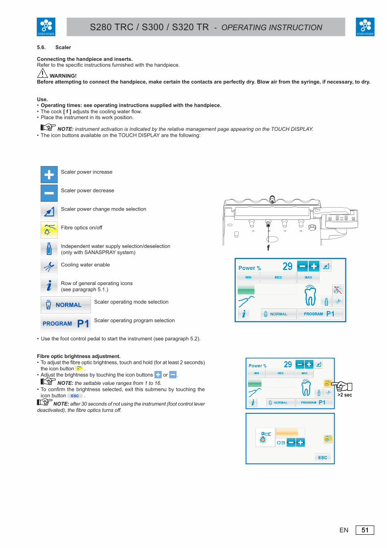
5151
�
������
S280 TRC / S300 / S320 TR - OPERATING INSTRUCTION
51EN
5.6. Scaler
Connecting the handpiece and inserts. Refer to the specific instructions furnished with the handpiece.
WARNING!Before attempting to connect the handpiece, make certain the contacts are perfectly dry. Blow air from the syringe, if necessary, to dry.
Use.• Operating times: see operating instructions supplied with the handpiece.• The cock [ f ] adjusts the cooling water flow.• Place the instrument in its work position.
NOTE: instrument activation is indicated by the relative management page appearing on the TOUCH DISPLAY. • The icon buttons available on the TOUCH DISPLAY are the following:
Scaler power increase
Scaler power decrease
Scaler power change mode selection
Fibre optics on/off
Independent water supply selection/deselection (only with SANASPRAY system)
Cooling water enable
Row of general operating icons (see paragraph 5.1.)
Scaler operating mode selection
Scaler operating program selection
• Use the foot control pedal to start the instrument (see paragraph 5.2).
Fibre optic brightness adjustment.• To adjust the fibre optic brightness, touch and hold (for at least 2 seconds)
the icon button .• Adjust the brightness by touching the icon buttons or .
NOTE: the settable value ranges from 1 to 16.• To confirm the brightness selected, exit this submenu by touching the
icon button . NOTE: after 30 seconds of not using the instrument (foot control lever
deactivated), the fibre optics turns off.
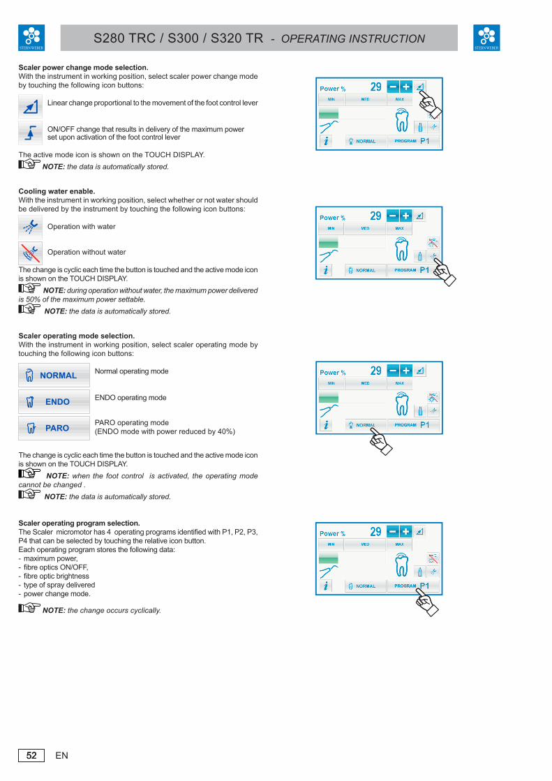
5252
S280 TRC / S300 / S320 TR - OPERATING INSTRUCTION
52 EN
Scaler power change mode selection.With the instrument in working position, select scaler power change mode by touching the following icon buttons:
Linear change proportional to the movement of the foot control lever
ON/OFF change that results in delivery of the maximum power
set upon activation of the foot control lever
The active mode icon is shown on the TOUCH DISPLAY. NOTE: the data is automatically stored.
Cooling water enable.With the instrument in working position, select whether or not water should be delivered by the instrument by touching the following icon buttons:
Operation with water
Operation without water The change is cyclic each time the button is touched and the active mode icon is shown on the TOUCH DISPLAY.
NOTE: during operation without water, the maximum power delivered is 50% of the maximum power settable.
NOTE: the data is automatically stored.
Scaler operating mode selection.With the instrument in working position, select scaler operating mode by touching the following icon buttons:
Normal operating mode
ENDO operating mode
PARO operating mode (ENDO mode with power reduced by 40%)
The change is cyclic each time the button is touched and the active mode icon is shown on the TOUCH DISPLAY.
NOTE: when the foot control is activated, the operating mode cannot be changed .
NOTE: the data is automatically stored.
Scaler operating program selection.The Scaler micromotor has 4 operating programs identified with P1, P2, P3, P4 that can be selected by touching the relative icon button.Each operating program stores the following data:- maximum power,- fibre optics ON/OFF,- fibre optic brightness- type of spray delivered- power change mode.
NOTE: the change occurs cyclically.
5353
S280 TRC / S300 / S320 TR - OPERATING INSTRUCTION
53EN
Removable cordThe scaler has a removable cord to ease cleaning (see paragraph 5.).
Cleaning and care.Refer to the specific instructions furnished with the instrument.
WARNING!• Do not soak the handpiece in liquid disinfectants or detergents.
Sterilization.• Torque wrench, scaler bits and scaler handpiece: steam autoclave at 135°C (2 bar) following the instructions for use of the device.
WARNING!Carefully read the operating instructions supplied with the instrument before attempting to sterilize.
Safety standards.
WARNING!• The instrument is supplied NOT STERILE and must be sterilized before use (see paragraph 1.5.). Before performing sterilization, check the instructions for use included with the device.• Only for American and Canadian markets: instruments must be FDA-approved.• Make sure the threaded sections of the inserts and handpiece are perfectly clean.• Do not change the shape of the inserts.• Check wear and tear of the inserts on a regular basis, replacing them in the following cases: - obvious wear. - drop in performance. - out of shape or banged.• Notes on SC-a3 descalers: - Class 1 LED apparatus; - Do not direct the light beam in anyone's eyes when cleaning or servicing the device (it is recommended to keep the fi ber optics shut off).• To avoid hazards or malfunctions When connecting the board, do not reverse the positions of the cords for scalers that are different
brands. • The inserts attached to the handpiece must comply to Biocompatibility standard ISO 10993.
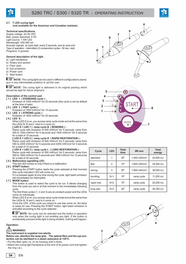
5454
�
�
��
�
�
�
�
��
�
���
�
Cycle LED Total time Ø8 mm Total
energy
standard 1 20" 1.000 mW/cm2 20.000 mJ
fast 2 15" 1.600 mW/cm2 24.000 mJ
strong 3 20" 1.800 mW/cm2 36.000 mJ
bonding S+1 15" ramp cycle 11.250 mJ
rapid rest. S+2 15" ramp cycle 20.250 mJ
long rest. S+3 20" ramp cycle 26.250 mJ
S280 TRC / S300 / S320 TR - OPERATING INSTRUCTION
54 EN
5.7. T LED curing light(not available for the American and Canadian markets)
Technical specifications.Supply voltage: 24-36 VDCMax. power absorbed: 6 VALight source: 1 5W LEDWavelength: 430-490 nmAcoustic signals: at cycle start, every 5 seconds, and at cycle endType of operation : intermittent (3 consecutive cycles - 60 sec. rest)Programs: 6 (preset)
General description of the lighta) Light handpieceb) Rotary end sectionc) Fiber opticd) Eye protectione) Power cordf) Start button
NOTE: The curing light can be used in different configurations (wand, gun or any intermediate position) to aid the user.
NOTE: The curing light is delivered in its original packing which should be kept for future shipment.
Description of the control pad[ 1 ] LED 1 ( STANDARD cycle ) :
Emission of 1000 mW/cm2 for 20 seconds (this cycle is set as default at the time of sale).
[ 2 ] LED 2 ( FAST cycle ) : Emission of 1600 mW/cm2 for 15 seconds.[ 3 ] LED 3 ( STRONG cycle ) : Emission of 1800 mW/cm2 for 20 seconds. [ 4 ] LED S : When LED S is on, you access ramp cycle mode and at the same time
the LEDs B, R and L next to it come on:[ LED S + LED 1 ] ramp cycle B ( BONDING ) :Ramp cycle with emission of 500 mW/cm2 for 5 seconds, ramp from 500 to 1000 mW/cm2 for 5 seconds and 1000 mW/cm2 for 5 seconds for a total of 15 seconds. [ LED S + LED 2 ] ramp cycle R ( RAPID RESTORATION ) :Ramp cycle with emission of 500 mW/cm2 for 5 seconds, ramp from 500 to 2200 mW/cm2 for 5 seconds and 2200 mW/cm2 for 5 seconds for a total of 15 seconds. [ LED S + LED 3 ] ramp cycle L ( LONG RESTORATION ) :Ramp cycle with emission of 500 mW/cm2 for 5 seconds, ramp from 500 to 1800 mW/cm2 for 5 seconds and 1800 mW/cm2 for 10 seconds for a total of 20 seconds.
[ 5 ] Malfunction signalling LED: This red LED comes on only if there is a malfunction. [ 6 ] START button: Pressing the START button starts the cycle selected at that moment
(the cycle indication LED will come on). If it is pressed again at any time during the cycle, light beam emission
will immediately be interrupted.[ 7 ] MODE button: This button is used to select the cycle to be run. It allows changing
from the cycle you are in at that moment to the immediately following cycle.
The first three cycles (1, 2 and 3) are at constant power and the LEDs come on individually.
When LED S is on, you access ramp cycle mode and at the same time the LEDs B, R and L next to it come on.
Once the LED of the cycle you intend to use has come on, the lamp is ready for use. Pressing the START button, light beam emission is activated according to the cycle selected .
NOTE: the cycle can be selected and the button is operative only when the curing light is not emitting any light. If the button is accidentally pressed while light is being emitted, nothing will happen.
Operation.
WARNING!The instrument is supplied non-sterile.Before use, disinfect the lamp grip. The optical fibre and the eye pro-tection can be sterilized in a steam autoclave at 135°C.• Put the fiber optic ( c ) in its housing until it clicks.• Attach the curing light handpiece to the end of its power cord and tighten
the ring ( e ).
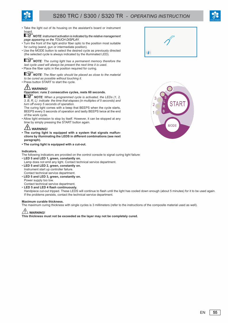
5555
S280 TRC / S300 / S320 TR - OPERATING INSTRUCTION
55EN
• Take the light out of its housing on the assistant’s board or instrument board.
NOTE: instrument activation is indicated by the relative management page appearing on the TOUCH DISPLAY.
• Turn the front of the light and/or fiber optic to the position most suitable for curing (wand, gun or intermediate position).
• Use the MODE button to select the desired cycle as previously directed (the selected cycle is always indicated by the illuminated LED).
NOTE: The curing light has a permanent memory therefore the last cycle used will always be present the next time it is used.
• Place the fiber optic in the position required for curing.
NOTE: The fiber optic should be placed as close to the material to be cured as possible without touching it.
• Press button START to start the cycle.
WARNING!Operation: runs 2 consecutive cycles, rests 60 seconds.
NOTE: When a programmed cycle is activated, the LEDs (1, 2, 3, B, R, L) indicate the time that elapses (in multiples of 5 seconds) and turn off every 5 seconds of operation.
The curing light comes with a beep that BEEPS when the cycle starts, BEEPS every 5 seconds of operation and lastly BEEPS twice at the end of the work cycle.
• Allow light emission to stop by itself. However, it can be stopped at any time by simply pressing the START button again.
WARNING!• The curing light is equipped with a system that signals malfun-
ctions by illuminating the LEDS in different combinations (see next paragraph).
• The curing light is equipped with a cut-out.
Indicators. The following indicators are provided on the control console to signal curing light failure:• LED 5 and LED 1, green, constantly on. Lamp does not emit any light. Contact technical service department.• LED 5 and LED 2, green, constantly on. Instrument start up controller failure. Contact technical service department.• LED 5 and LED 3, green, constantly on. Power supply too low. Contact technical service department.• LED 5 and LED 4 flash continuously. Handpiece cut-out tripped. These LEDS will continue to flash until the light has cooled down enough (about 5 minutes) for it to be used again. If the problems persists, contact the technical service department.
Maximum curable thickness.The maximum curing thickness with single cycles is 3 millimeters (refer to the instructions of the composite material used as well).
WARNING!This thickness must not be exceeded as the layer may not be completely cured.
5656
S280 TRC / S300 / S320 TR - OPERATING INSTRUCTION
56 EN
Safety guidelines.
WARNING!• The LED is a Class 2 light source in accordance with IEC 62471. DO NOT FIX THE BEAM. The light emitted may cause eye damage in the event of direct radiation without eye protection. Eye protection must always be worn when using the curing lamp and do not direct the light beam in eyes. The light emitted may damage soft tissues (oral cavity mucous, gums, skin). Be extremely careful to direct the light precisely on the material to be cured.• People with eye diseases, such as those who have had cataracts removed or retina diseases must be adequately protected when the
curing lamp is used, for example with s uitable protective eyewear.• The rotary end can turn 180° counter-clockwise in relation to the handpiece to change over from wand to gun configuration. To go back to wand configuration, turn clockwise. A click is heard when the two positions are reached. Do not turn any more once the click is heard. The intermediate positions can be used even if a click is not heard. Put the fiber optic back into the correct position after turning the end section. • Do not pull the power cord.• Do not expose the handpiece to excessive vibrations.• Do not drop the handpiece and in particular the fiber optic. The lamp may break if accidentally banged. Check the condition of the handpiece if it has been banged or dropped before using the curing light. Try to turn on the light and check operation
first without using it on the patient. If cracked, broken or if there are any other faults, do not use the curing light on the patient and contact the technical service department. The fiber optic is rather delicate and may crack or break if banged, affecting the final amount of light emitted. If dropped, carefully inspect the fiber
optic to verify if it is cracked or broken. If cracked, a strong light appears in the spot in which the fiber is cracked. In all these cases, the fiber optic must be replaced.
• The curing light handpiece (sold separately) can be connected only to dental units with connections for this curing lamp. Connection to any other equipment may damage the circuits inside the lamp and seriously injure the user and patient.
• The curing lamp handpiece is not protected against liquid penetration (IP20).• The curing lamp handpiece is not suitable for use in the presence of flammable anaesthetic gas mixed with air, oxygen or nitrous oxide (N2O).
Cleaning.The curing lamp may be a vehicle for cross contamination between patients. The most contaminated parts are the fiber optic and eye protection. Before sterilizing them, make sure there are no residues of curing products: if necessary, clean with alcohol or a plastic spatula.Exclusively sterilize the optical fibre and the eye protection in an autoclave at a sterilization temperature of at least 134°C.
WARNING!• The fiber optic is able to support 500 autoclave cycles after which it tends to become opaque and therefore emit less light.• The eye protection must also be replaced after 500 cycles.• Contact the manufacturer to purchase original spare parts (fiber optic + eye protection: code 97660404).
The handpiece cannot be put in autoclave; disinfect it on the outside with suitable products and cover it with disposable plastic wrap. Use soft dispo-sable paper towels to disinfect the handpiece. Do not use harsh products or soak in liquids.
WARNING!• The curing light handpiece is NOT suitable for autoclave.• The curing light handpiece is not protected against penetration of liquids therefore it CANNOT be soaked in solution to be sterilized.• The outside of the lamp should be disinfected with the fiber optic on. Do not use any type of disinfectant on the exposed optical surface
of the handpiece when the fiber is removed. The surface will become irreparably opaque if it comes into contact with disinfectant.
Maintenance.This equipment does not require any particular type of maintenance. Only technicians authorized by the manufacturer can replace and/or repair the handpiece and dental unit. The handpiece has been purposely constructed in a manner that requires specific tools to open it and therefore it cannot be removed by the user. The warranty is automatically void if the handpiece is altered in any way.
Troubleshooting.• When the lamp is removed, the light does not come on (no leds on control console illuminated). Make sure the Midwest connection is correctly attached to the power cord. Carefully screw the ring, try to turn on the lamp and then take it off again. If the problem persists, contact the technical service department.• Less light emitted - Make certain the fiber optic is not cracked or damaged in any way: replace it if it is. Contact the manufacturer to purchase original spare parts. - Make sure there are no residues of curing products on the end of the fiber optic: if necessary, wipe off with alcohol or a plastic spatula.If the handpiece has to be sent back, please disinfect it. Ship it back in its original packing. In addition, please enclose a description of the fault with the shipping note.
Disposal at end of service life.• Never throw out the equipment in regular trash.• Observe current local regulations regarding disposal of the equipment at the end of its service life.• Due to the possibility of cross contamination, disinfect the equipment before disposing.
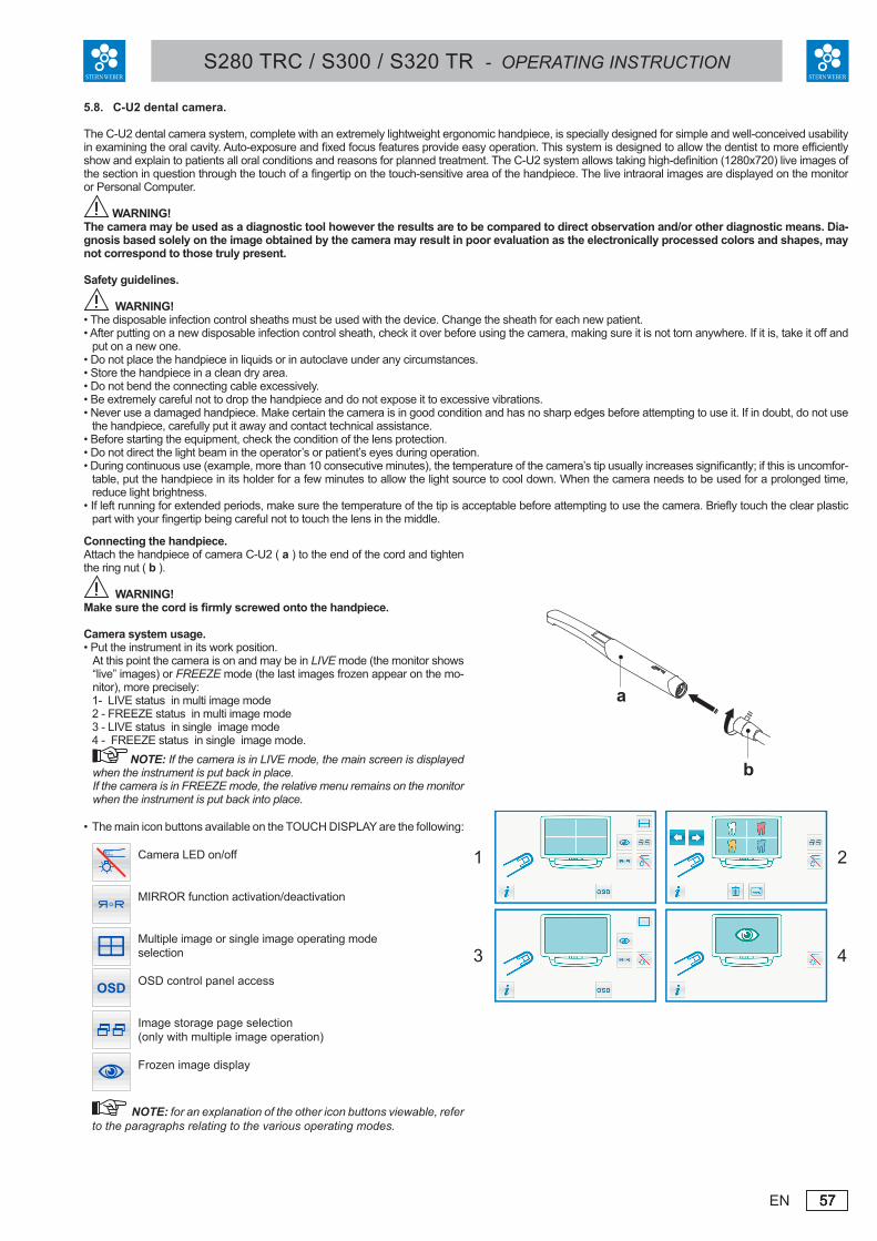
5757
�
�
� �
� �
S280 TRC / S300 / S320 TR - OPERATING INSTRUCTION
57EN
5.8. C-U2 dental camera.
The C-U2 dental camera system, complete with an extremely lightweight ergonomic handpiece, is specially designed for simple and well-conceived usability in examining the oral cavity. Auto-exposure and fixed focus features provide easy operation. This system is designed to allow the dentist to more efficiently show and explain to patients all oral conditions and reasons for planned treatment. The C-U2 system allows taking high-definition (1280x720) live images of the section in question through the touch of a fingertip on the touch-sensitive area of the handpiece. The live intraoral images are displayed on the monitor or Personal Computer.
WARNING!The camera may be used as a diagnostic tool however the results are to be compared to direct observation and/or other diagnostic means. Dia-gnosis based solely on the image obtained by the camera may result in poor evaluation as the electronically processed colors and shapes, may not correspond to those truly present.
Safety guidelines.
WARNING!• The disposable infection control sheaths must be used with the device. Change the sheath for each new patient. • After putting on a new disposable infection control sheath, check it over before using the camera, making sure it is not torn anywhere. If it is, take it off and
put on a new one. • Do not place the handpiece in liquids or in autoclave under any circumstances.• Store the handpiece in a clean dry area.• Do not bend the connecting cable excessively.• Be extremely careful not to drop the handpiece and do not expose it to excessive vibrations.• Never use a damaged handpiece. Make certain the camera is in good condition and has no sharp edges before attempting to use it. If in doubt, do not use
the handpiece, carefully put it away and contact technical assistance. • Before starting the equipment, check the condition of the lens protection. • Do not direct the light beam in the operator’s or patient’s eyes during operation.• During continuous use (example, more than 10 consecutive minutes), the temperature of the camera’s tip usually increases significantly; if this is uncomfor-
table, put the handpiece in its holder for a few minutes to allow the light source to cool down. When the camera needs to be used for a prolonged time, reduce light brightness.
• If left running for extended periods, make sure the temperature of the tip is acceptable before attempting to use the camera. Briefly touch the clear plastic part with your fingertip being careful not to touch the lens in the middle.
Connecting the handpiece.Attach the handpiece of camera C-U2 ( a ) to the end of the cord and tighten the ring nut ( b ).
WARNING!Make sure the cord is firmly screwed onto the handpiece.
Camera system usage.• Put the instrument in its work position. At this point the camera is on and may be in LIVE mode (the monitor shows
“live” images) or FREEZE mode (the last images frozen appear on the mo-nitor), more precisely:1- LIVE status in multi image mode2 - FREEZE status in multi image mode3 - LIVE status in single image mode4 - FREEZE status in single image mode.
NOTE: If the camera is in LIVE mode, the main screen is displayed when the instrument is put back in place.
If the camera is in FREEZE mode, the relative menu remains on the monitor when the instrument is put back into place.
• The main icon buttons available on the TOUCH DISPLAY are the following:
Camera LED on/off
MIRROR function activation/deactivation
Multiple image or single image operating mode selection
OSD control panel access
Image storage page selection (only with multiple image operation)
Frozen image display
NOTE: for an explanation of the other icon buttons viewable, refer to the paragraphs relating to the various operating modes.
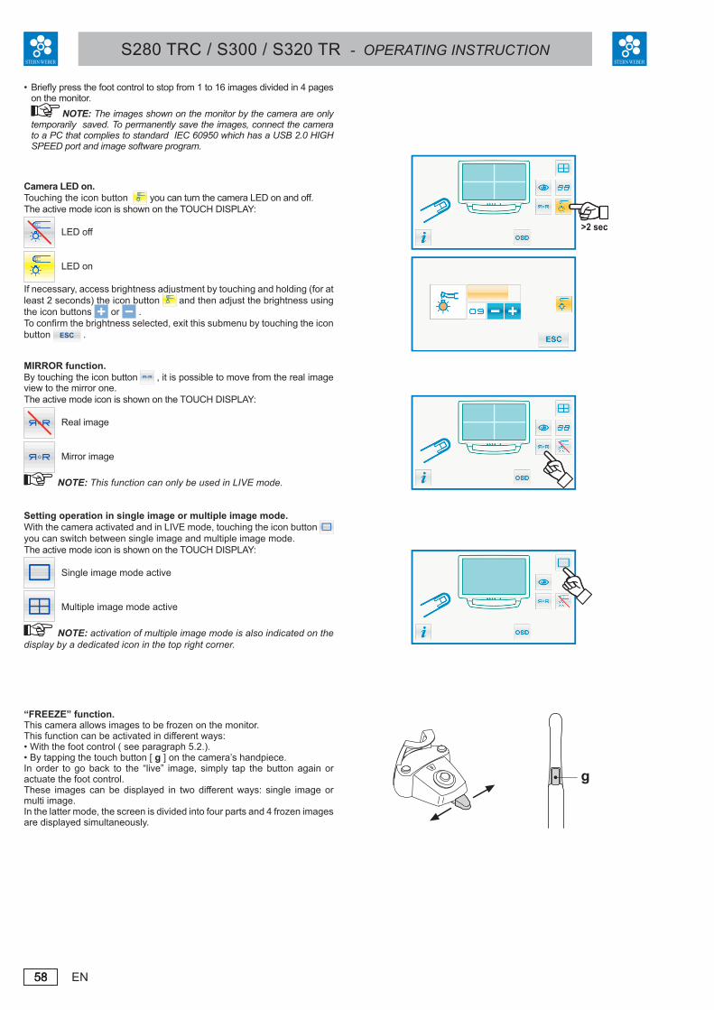
5858
������
�
S280 TRC / S300 / S320 TR - OPERATING INSTRUCTION
58 EN
• Briefly press the foot control to stop from 1 to 16 images divided in 4 pages on the monitor.
NOTE: The images shown on the monitor by the camera are only temporarily saved. To permanently save the images, connect the camera to a PC that complies to standard IEC 60950 which has a USB 2.0 HIGH SPEED port and image software program.
Camera LED on.Touching the icon button you can turn the camera LED on and off. The active mode icon is shown on the TOUCH DISPLAY:
LED off
LED on
If necessary, access brightness adjustment by touching and holding (for at least 2 seconds) the icon button and then adjust the brightness using the icon buttons or .To confirm the brightness selected, exit this submenu by touching the icon button .
MIRROR function.By touching the icon button , it is possible to move from the real image view to the mirror one.The active mode icon is shown on the TOUCH DISPLAY:
Real image
Mirror image
NOTE: This function can only be used in LIVE mode.
Setting operation in single image or multiple image mode.With the camera activated and in LIVE mode, touching the icon button you can switch between single image and multiple image mode.The active mode icon is shown on the TOUCH DISPLAY:
Single image mode active
Multiple image mode active
NOTE: activation of multiple image mode is also indicated on the display by a dedicated icon in the top right corner.
“FREEZE” function.This camera allows images to be frozen on the monitor.This function can be activated in different ways: • With the foot control ( see paragraph 5.2.).• By tapping the touch button [ g ] on the camera’s handpiece.In order to go back to the “live” image, simply tap the button again or actuate the foot control. These images can be displayed in two different ways: single image or multi image.In the latter mode, the screen is divided into four parts and 4 frozen images are displayed simultaneously.
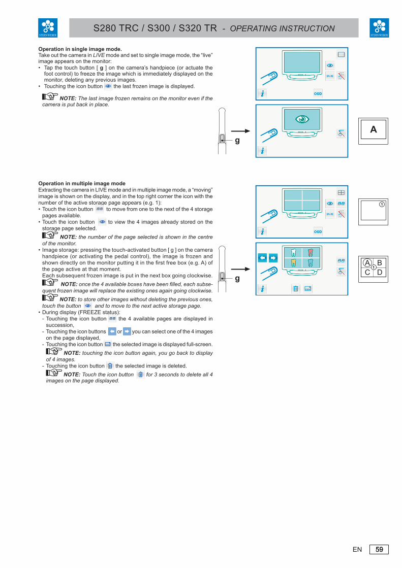
5959
��
���
� ��
S280 TRC / S300 / S320 TR - OPERATING INSTRUCTION
59EN
Operation in single image mode.Take out the camera in LIVE mode and set to single image mode, the “live” image appears on the monitor: • Tap the touch button [ g ] on the camera’s handpiece (or actuate the
foot control) to freeze the image which is immediately displayed on the monitor, deleting any previous images.
• Touching the icon button the last frozen image is displayed.
NOTE: The last image frozen remains on the monitor even if the camera is put back in place.
Operation in multiple image modeExtracting the camera in LIVE mode and in multiple image mode, a “moving” image is shown on the display, and in the top right corner the icon with the number of the active storage page appears (e.g. 1): • Touch the icon button to move from one to the next of the 4 storage
pages available. • Touch the icon button to view the 4 images already stored on the
storage page selected. NOTE: the number of the page selected is shown in the centre
of the monitor.• Image storage: pressing the touch-activated button [ g ] on the camera
handpiece (or activating the pedal control), the image is frozen and shown directly on the monitor putting it in the first free box (e.g. A) of the page active at that moment.
Each subsequent frozen image is put in the next box going clockwise. NOTE: once the 4 available boxes have been filled, each subse-
quent frozen image will replace the existing ones again going clockwise. NOTE: to store other images without deleting the previous ones,
touch the button and to move to the next active storage page. • During display (FREEZE status):
- Touching the icon button the 4 available pages are displayed in succession,
- Touching the icon buttons or you can select one of the 4 images on the page displayed,
- Touching the icon button the selected image is displayed full-screen. NOTE: touching the icon button again, you go back to display
of 4 images.- Touching the icon button the selected image is deleted.
NOTE: Touch the icon button for 3 seconds to delete all 4 images on the page displayed.
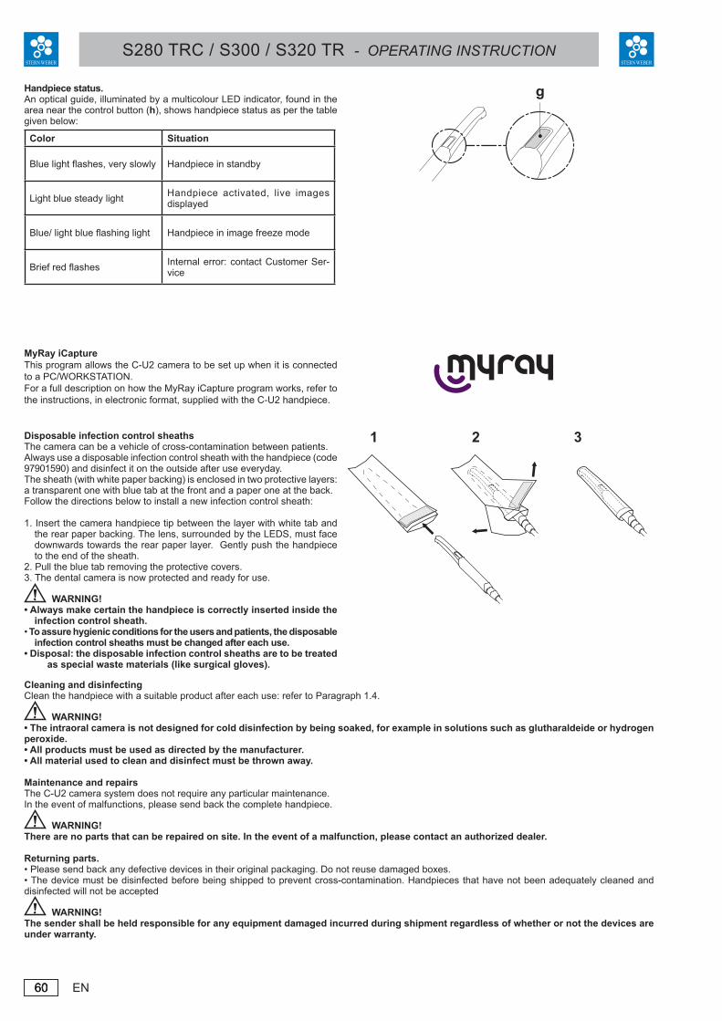
6060
� � �
�
S280 TRC / S300 / S320 TR - OPERATING INSTRUCTION
60 EN
Disposable infection control sheathsThe camera can be a vehicle of cross-contamination between patients. Always use a disposable infection control sheath with the handpiece (code 97901590) and disinfect it on the outside after use everyday. The sheath (with white paper backing) is enclosed in two protective layers: a transparent one with blue tab at the front and a paper one at the back. Follow the directions below to install a new infection control sheath:
1. Insert the camera handpiece tip between the layer with white tab and the rear paper backing. The lens, surrounded by the LEDS, must face downwards towards the rear paper layer. Gently push the handpiece to the end of the sheath.
2. Pull the blue tab removing the protective covers. 3. The dental camera is now protected and ready for use.
WARNING!• Always make certain the handpiece is correctly inserted inside the
infection control sheath. • To assure hygienic conditions for the users and patients, the disposable
infection control sheaths must be changed after each use. • Disposal: the disposable infection control sheaths are to be treated
as special waste materials (like surgical gloves).
Cleaning and disinfecting Clean the handpiece with a suitable product after each use: refer to Paragraph 1.4.
WARNING!• The intraoral camera is not designed for cold disinfection by being soaked, for example in solutions such as glutharaldeide or hydrogen peroxide.• All products must be used as directed by the manufacturer.• All material used to clean and disinfect must be thrown away.
Maintenance and repairs The C-U2 camera system does not require any particular maintenance.In the event of malfunctions, please send back the complete handpiece.
WARNING!There are no parts that can be repaired on site. In the event of a malfunction, please contact an authorized dealer.
Returning parts.• Please send back any defective devices in their original packaging. Do not reuse damaged boxes. • The device must be disinfected before being shipped to prevent cross-contamination. Handpieces that have not been adequately cleaned and disinfected will not be accepted
WARNING!The sender shall be held responsible for any equipment damaged incurred during shipment regardless of whether or not the devices are under warranty.
Handpiece status.An optical guide, illuminated by a multicolour LED indicator, found in the area near the control button (h), shows handpiece status as per the table given below:
Color Situation
Blue light flashes, very slowly Handpiece in standby
Light blue steady light Handpiece activated, live images displayed
Blue/ light blue flashing light Handpiece in image freeze mode
Brief red flashes Internal error: contact Customer Ser-vice
MyRay iCaptureThis program allows the C-U2 camera to be set up when it is connected to a PC/WORKSTATION. For a full description on how the MyRay iCapture program works, refer to the instructions, in electronic format, supplied with the C-U2 handpiece.
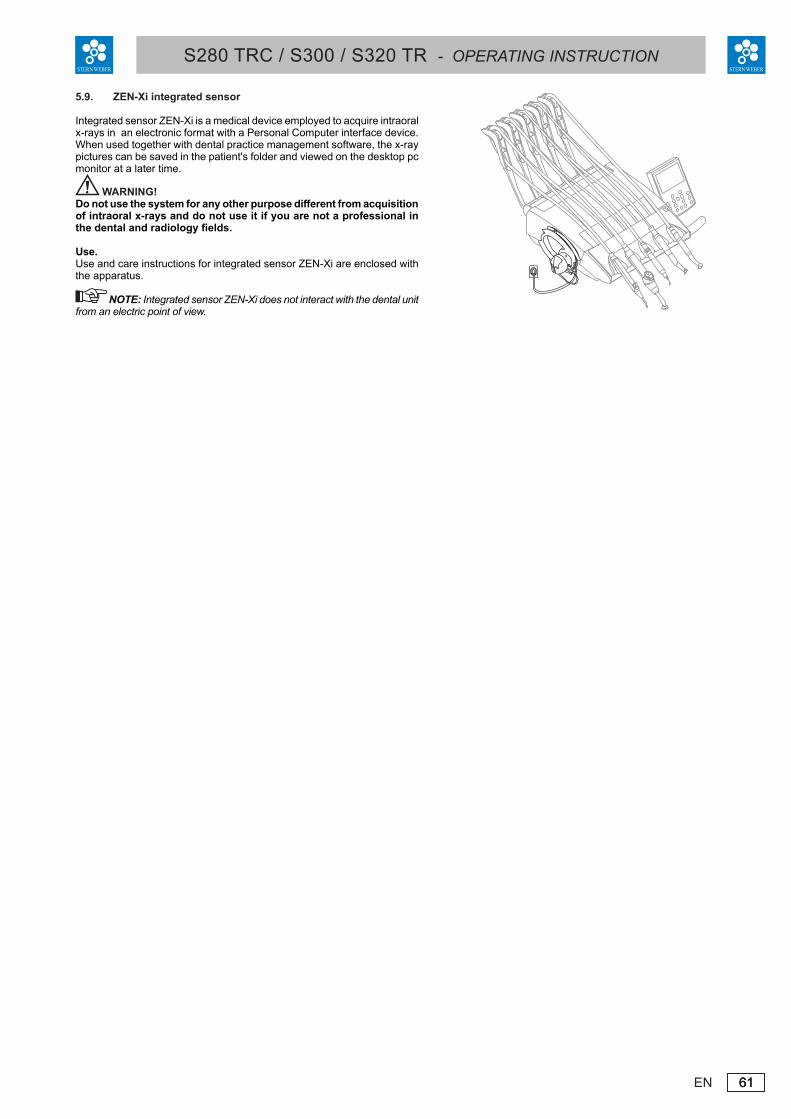
6161
S280 TRC / S300 / S320 TR - OPERATING INSTRUCTION
61EN
5.9. ZEN-Xi integrated sensor
Integrated sensor ZEN-Xi is a medical device employed to acquire intraoral x-rays in an electronic format with a Personal Computer interface device.When used together with dental practice management software, the x-ray pictures can be saved in the patient's folder and viewed on the desktop pc monitor at a later time.
WARNING!Do not use the system for any other purpose different from acquisition of intraoral x-rays and do not use it if you are not a professional in the dental and radiology fields.
Use.Use and care instructions for integrated sensor ZEN-Xi are enclosed with the apparatus.
NOTE: Integrated sensor ZEN-Xi does not interact with the dental unit from an electric point of view.
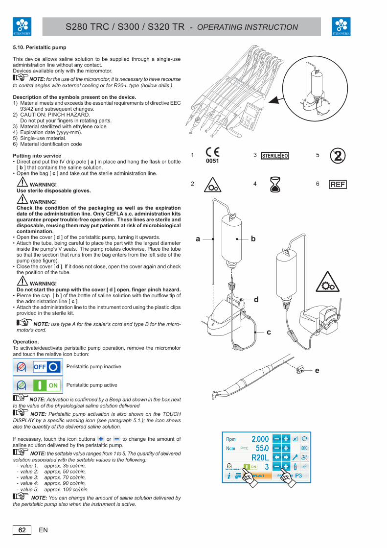
6262
� �
�
�
�
�
�
����
�
� �
�
S280 TRC / S300 / S320 TR - OPERATING INSTRUCTION
62 EN
5.10. Peristaltic pump
This device allows saline solution to be supplied through a single-use administration line without any contact. Devices available only with the micromotor.
NOTE: for the use of the micromotor, it is necessary to have recourse to contra angles with external cooling or for R20-L type (hollow drills ).
Description of the symbols present on the device. 1) Material meets and exceeds the essential requirements of directive EEC
93/42 and subsequent changes.2) CAUTION: PINCH HAZARD. Do not put your fingers in rotating parts. 3) Material sterilized with ethylene oxide4) Expiration date (yyyy-mm).5) Single-use material.6) Material identification code
Putting into service• Direct and put the IV drip pole [ a ] in place and hang the flask or bottle
[ b ] that contains the saline solution.• Open the bag [ c ] and take out the sterile administration line.
WARNING!Use sterile disposable gloves.
WARNING!Check the condition of the packaging as well as the expiration date of the administration line. Only CEFLA s.c. administration kits guarantee proper trouble-free operation. These lines are sterile and disposable, reusing them may put patients at risk of microbiological contamination.
• Open the cover [ d ] of the peristaltic pump, turning it upwards. • Attach the tube, being careful to place the part with the largest diameter
inside the pump's V seats. The pump rotates clockwise. Place the tube so that the section that runs from the bag enters from the left side of the pump (see figure).
• Close the cover [ d ]. If it does not close, open the cover again and check the position of the tube.
WARNING!Do not start the pump with the cover [ d ] open, finger pinch hazard.
• Pierce the cap [ b ] of the bottle of saline solution with the outflow tip of the administration line [ c ].
• Attach the administration line to the instrument cord using the plastic clips provided in the sterile kit.
NOTE: use type A for the scaler's cord and type B for the micro-motor's cord.
Operation.To activate/deactivate peristaltic pump operation, remove the micromotor and touch the relative icon button:
Peristaltic pump inactive
Peristaltic pump active
NOTE: Activation is confirmed by a Beep and shown in the box next
to the value of the physiological saline solution delivered NOTE: Peristaltic pump activation is also shown on the TOUCH
DISPLAY by a specific warning icon (see paragraph 5.1.); the icon shows also the quantity of the delivered saline solution.
If necessary, touch the icon buttons or to change the amount of saline solution delivered by the peristaltic pump.
NOTE: the settable value ranges from 1 to 5. The quantity of delivered solution associated with the settable values is the following:
- value 1: approx. 35 cc/min,- value 2: approx. 50 cc/min,- value 3: approx. 70 cc/min,- value 4: approx. 90 cc/min,- value 5: approx. 100 cc/min.
NOTE: You can change the amount of saline solution delivered by the peristaltic pump also when the instrument is active.
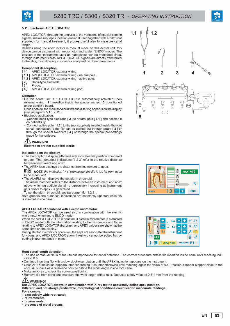
6363
����
��� ���
�
S280 TRC / S300 / S320 TR - OPERATING INSTRUCTION
63EN
5.11. Electronic APEX LOCATOR
APEX LOCATOR, through the analysis of the variations of special electric signals, makes root apex location easier. If used together with a "file" (not supplied) for manual treatment, it proves useful also to measure canal length. Besides using the apex locator in manual mode on this dental unit, this device can be also used with micromotor and scaler "ENDO" modes. The position of the instruments used on handpieces can be monitored since, through instrument cords, APEX LOCATOR signals are directly transferred to the files, thus allowing to monitor canal position during treatments.
Component description.[ 1 ] APEX LOCATOR external wiring.[ 1.1 ] APEX LOCATOR external wiring - neutral pole.[ 1.2 ] APEX LOCATOR external wiring - active pole.[ 2 ] Hook-type electrode.[ 3 ] Probe.[ 4 ] APEX LOCATOR external wiring port.
Operation.• On this dental unit, APEX LOCATOR is automatically activated upon
external wiring [ 1 ] insertion inside the special socket [ 5 ] positioned under dentist's board.
Once enabled, the menu for alarm threshold setting appears on the display (see paragraph 5.1.1.2.11.).
• Electrode application:- Connect hook-type electrode [ 2 ] to neutral pole [ 1.1 ] and position it
on patient's lip. - Connect active pole [ 1.2 ] to file (not supplied) inserted inside the root
canal; connection to the file can be carried out through probe [ 3 ] or through the special tweezers [ 4 ] or through the special pre-settings made for handpieces.
WARNING!Electrodes are not supplied sterile.
Indications on the display. • The bargraph on display left-hand side indicates file position compared
to apex. The numerical indications "1 2 3" refer to the relative distance between instrument and apex.
• The APEX icon displays the distance from instrument to apex. NOTE: the indication "> 4" signals that the file is too far from apex
to be measured. • The ALARM icon displays the set alarm threshold.
The alarm threshold refers to the distance between instrument and apex above which an audible signal - progressively increasing as instrument gets closer to apex - is generated. To set the alarm threshold, see paragraph 5.1.1.2.11.
Both graphic and numerical indications are constantly updated while file is inserted inside canal.
APEX LOCATOR combined with electric micromotor.The APEX LOCATOR can be used also in combination with the electric micromotor when set to ENDO mode.When the APEX LOCATOR is enabled, if electric micromotor is extracted in ENDO mode both the information relating to the micromotor and those relating to APEX LOCATOR (bargraph and APEX values) are shown at the same time on the display.During electric micromotor operation, the keys are associated to instrument functions, and APEX LOCATOR alarm threshold cannot be edited but by putting instrument back in place.
Root canal length detection.• The use of manual file is of the utmost importance for canal detection. The correct procedure entails file insertion inside canal until reaching indi-
cation 0.5. • Continue inserting file with a slow clockwise rotation until the APEX indication appears on the instrument. • Once APEX indication appears, stop file turning it counter clockwise until reaching again the value of 0.5. Position a rubber stopper close to the
occlusal surface as a reference point to define the work length inside root canal. • Make an X-ray to check file correct positioning. • Remove file from canal and measure the work length with a ruler. Deduct a safety value of 0.5-1 mm from the reading.
WARNING!Use APEX LOCATOR always in combination with X-ray test to accurately define apex position. Different, and not always predictable, morphological conditions could lead to inaccurate readings. For example:- excessively wide root canal; - re-treatments; - broken roots; - presence of metal crowns.
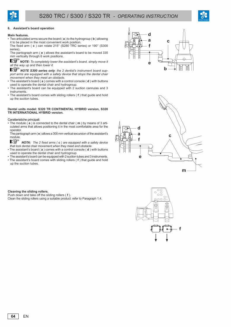
6464
�
�
��
��
�
�
�
�
��
�
S280 TRC / S300 / S320 TR - OPERATING INSTRUCTION
64 EN
6. Assistant’s board operation
Main features.• Two articulated arms secure the board ( a ) to the hydrogroup ( b ) allowing
it to be placed in the most convenient work position. Thefixedarm(c ) can rotate 215° (S280 TRC series) or 190° (S300
series). The pantograph arm ( e ) allows the assistant’s board to be moved 335
mm vertically through 6 work positions.
NOTE: To completely lower the assistant’s board, simply move it all the way up and then lower it.
NOTE S300 series only: the 2 dentist's instrument board sup-port arms are equipped with a safety device that stops the dental chair movement when they meet an obstacle.
• The assistant’s board ( a ) comes with a control console ( d ) with buttons used to operate the dental chair and hydrogroup.
• The assistant's board can be equipped with 2 suction cannulas and 3 instruments.
• The assistant’s board comes with sliding rollers ( f ) that guide and hold up the suction tubes.
Dental units model: S320 TR CONTINENTAL HYBRID version, S320 TR INTERNATIONAL HYBRID version.
Caratteristiche principali:• The module ( a ) is connected to the dental chair ( m ) by means of 3 arti-
culated arms that allows positioning it in the most comfortable area for the operator.
The pantograph arm ( e)allowsa300mmverticalexcursionoftheassistant’smodule.
NOTA: The 2 fixed arms ( c ) are equipped with a safety device that lock dental chair movement when they meet and obstacle.
• The assistant’s board ( a ) comes with a control console ( d ) with buttons used to operate the dental chair and hydrogroup.
• The assistant’s board can be equipped with 2 suction tubes and 3 instruments. • The assistant’s board comes with sliding rollers ( f ) that guide and hold
up the suction tubes.
Cleaning the sliding rollers.Pushdownandtakeofftheslidingrollers(f ).Clean the sliding rollers using a suitable product: refer to Paragraph 1.4.
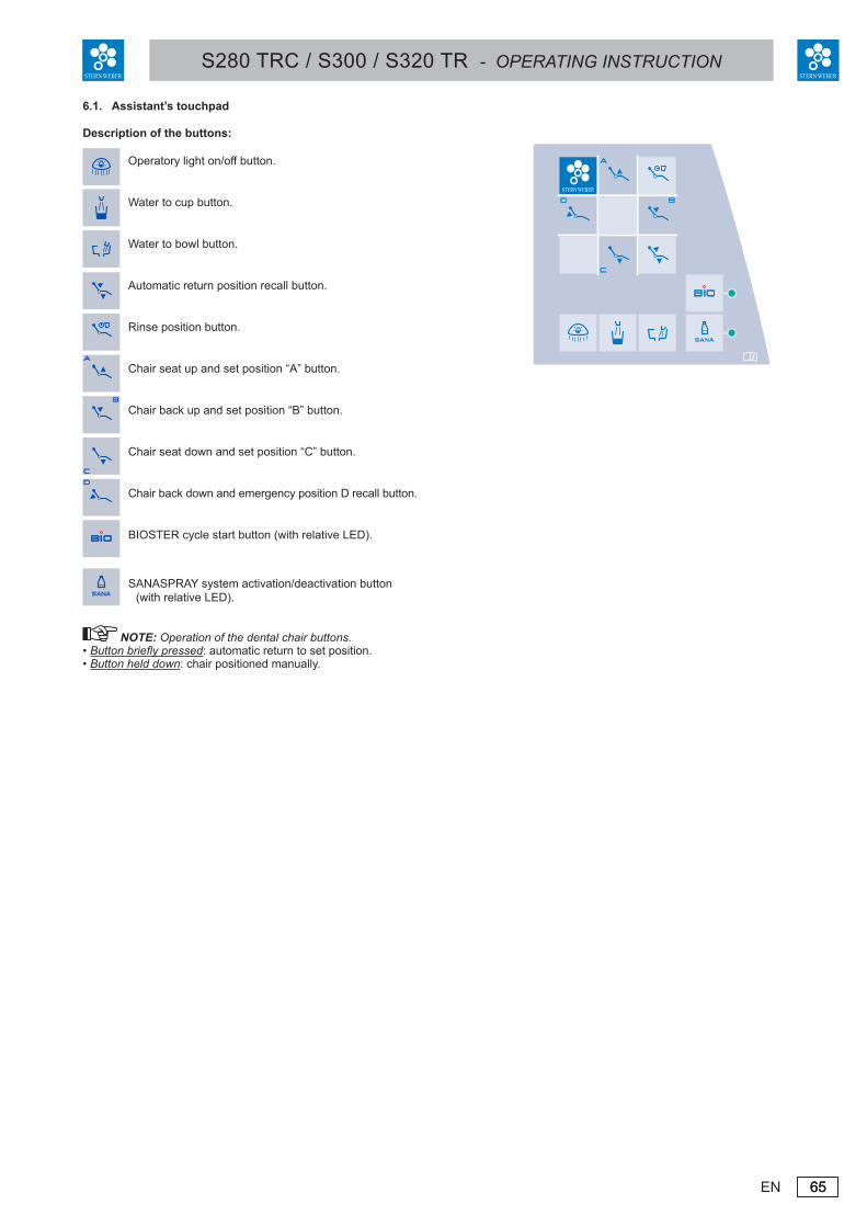
6565
S280 TRC / S300 / S320 TR - OPERATING INSTRUCTION
65EN
6.1. Assistant’s touchpad
Description of the buttons:
Operatorylighton/offbutton.
Water to cup button.
Water to bowl button.
Automatic return position recall button.
Rinse position button.
Chair seat up and set position “A” button.
Chair back up and set position “B” button.
Chair seat down and set position “C” button.
Chair back down and emergency position D recall button.
BIOSTER cycle start button (with relative LED).
SANASPRAY system activation/deactivation button (with relative LED).
NOTE: Operation of the dental chair buttons.• Button briefly pressed: automatic return to set position.• Button held down: chair positioned manually.
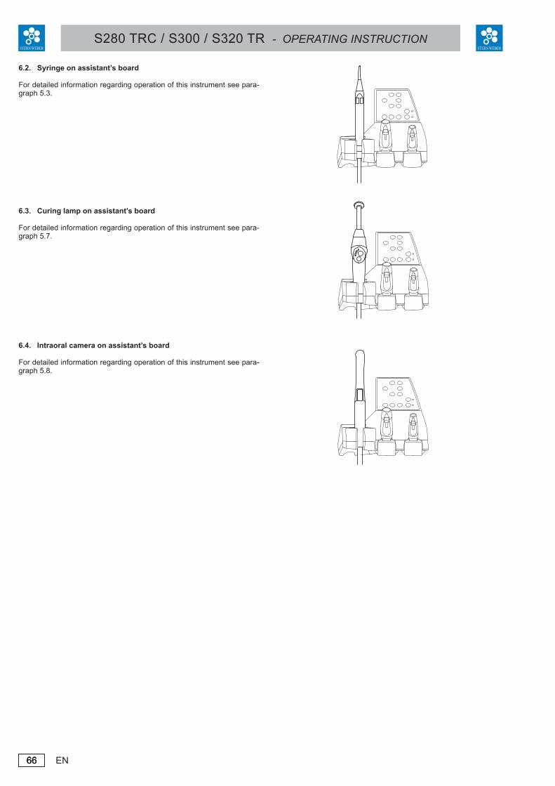
6666
S280 TRC / S300 / S320 TR - OPERATING INSTRUCTION
66 EN
6.2. Syringe on assistant’s board
For detailed information regarding operation of this instrument see para-graph 5.3.
6.3. Curing lamp on assistant’s board
For detailed information regarding operation of this instrument see para-graph 5.7.
6.4. Intraoral camera on assistant’s board
For detailed information regarding operation of this instrument see para-graph 5.8.
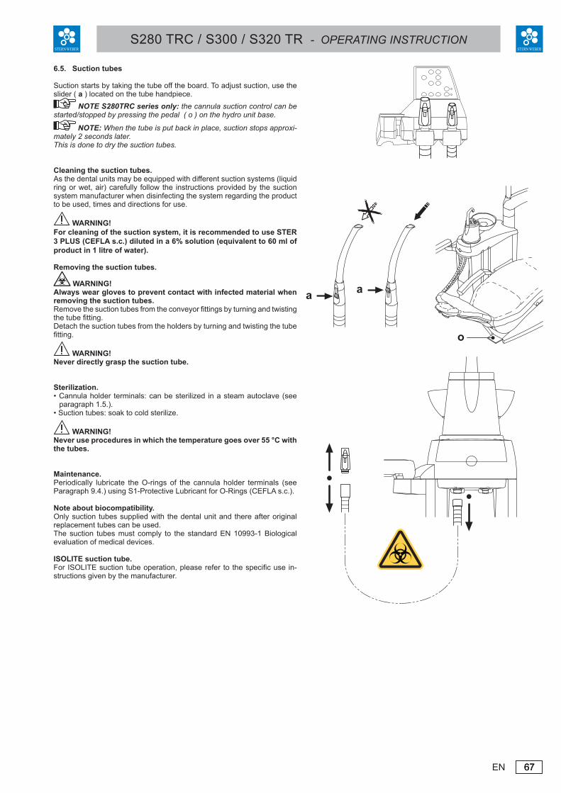
6767
�
��
S280 TRC / S300 / S320 TR - OPERATING INSTRUCTION
67EN
6.5. Suction tubes
Suctionstartsbytakingthetubeofftheboard.Toadjustsuction,usetheslider ( a ) located on the tube handpiece.
NOTE S280TRC series only: the cannula suction control can be started/stopped by pressing the pedal ( o ) on the hydro unit base.
NOTE: When the tube is put back in place, suction stops approxi-mately 2 seconds later. This is done to dry the suction tubes.
Cleaning the suction tubes.Asthedentalunitsmaybeequippedwithdifferentsuctionsystems(liquidringorwet,air)carefully follow the instructionsprovidedby thesuctionsystem manufacturer when disinfecting the system regarding the product tobeused,timesanddirectionsforuse.
WARNING!For cleaning of the suction system, it is recommended to use STER 3 PLUS (CEFLA s.c.) diluted in a 6% solution (equivalent to 60 ml of product in 1 litre of water).
Removing the suction tubes.
WARNING!Always wear gloves to prevent contact with infected material when removing the suction tubes.Removethesuctiontubesfromtheconveyorfittingsbyturningandtwistingthetubefitting.Detach the suction tubes from the holders by turning and twisting the tube fitting.
WARNING!Never directly grasp the suction tube.
Sterilization.• Cannula holder terminals: can be sterilized in a steam autoclave (see
paragraph 1.5.).• Suction tubes: soak to cold sterilize.
WARNING!Never use procedures in which the temperature goes over 55 °C with the tubes.
Maintenance.Periodically lubricate the O-rings of the cannula holder terminals (see Paragraph 9.4.) using S1-Protective Lubricant for O-Rings (CEFLA s.c.).
Note about biocompatibility.Only suction tubes supplied with the dental unit and there after original replacement tubes can be used. The suction tubes must comply to the standard EN 10993-1 Biological evaluation of medical devices.
ISOLITE suction tube.ForISOLITEsuctiontubeoperation,pleaserefertothespecificusein-structions given by the manufacturer.
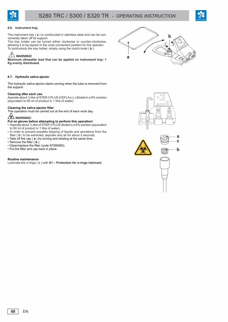
6868
�
��
�
�
S280 TRC / S300 / S320 TR - OPERATING INSTRUCTION
68 EN
6.6. Instrument tray.
The instrument tray ( a ) is constructed in stainless steel and can be con-venientlytakenoffitssupport.The tray holder can be turned either clockwise or counter-clockwise,allowing it to be placed in the most convenient position for the operator.Tolock/unlockthetrayholder,simplyusingtheclutchknob(b ).
WARNING!Maximum allowable load that can be applied on instrument tray: 1 Kg evenly distributed.
6.7. Hydraulic saliva ejector
Thehydraulicsalivaejectorstartsrunningwhenthetubeisremovedfromthe support.
Cleaning after each use.Aspirate about ½ litre of STER 3 PLUS (CEFLA s.c.) diluted in a 6% solution (equivalent to 60 ml of product in 1 litre of water).
Cleaning the saliva ejector filterThis operation must be carried out at the end of each work day.
WARNING!Put on gloves before attempting to perform this operation!• Aspirate about ½ litre of STER 3 PLUS diluted in a 6% solution (equivalent
to 60 ml of product in 1 litre of water).• In order to prevent possible dripping of liquids and secretions from the filter(b)tobeextracted,aspirateonlyairforabout5seconds.
•Takeoffthecap(a ) by turning and twisting at the same time.•Removethefilter(b ).•Clean/replacethefilter(code97290060).•Putthefilterandcapbackinplace.
Routine maintenanceLubricate the o-rings ( c ) with S1 – Protection for o-rings lubricant.
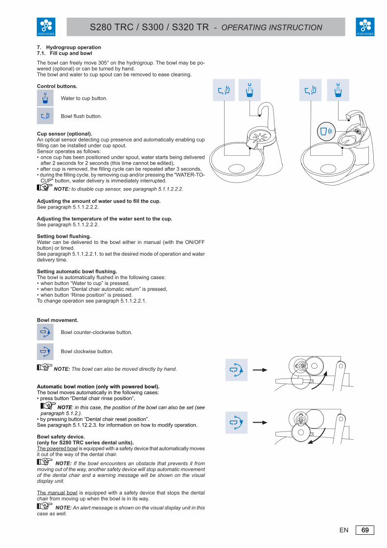
6969
S280 TRC / S300 / S320 TR - OPERATING INSTRUCTION
69EN
Bowl movement.
Bowl counter-clockwise button.
Bowl clockwise button.
NOTE: The bowl can also be moved directly by hand.
Automatic bowl motion (only with powered bowl).The bowl moves automatically in the following cases: •pressbutton“Dentalchairrinseposition”,
NOTE: in this case, the position of the bowl can also be set (see paragraph 5.1.2.).
• by pressing button “Dental chair reset position”.See paragraph 5.1.12.2.3. for information on how to modify operation.
Bowl safety device.(only for S280 TRC series dental units).The powered bowl is equipped with a safety device that automatically moves it out of the way of the dental chair.
NOTE: If the bowl encounters an obstacle that prevents it from moving out of the way, another safety device will stop automatic movement of the dental chair and a warning message will be shown on the visual display unit.
The manual bowl is equipped with a safety device that stops the dental chair from moving up when the bowl is in its way.
NOTE: An alert message is shown on the visual display unit in this case as well.
7. Hydrogroup operation7.1. Fill cup and bowl
The bowl can freely move 305° on the hydrogroup. The bowl may be po-wered (optional) or can be turned by hand.The bowl and water to cup spout can be removed to ease cleaning.
Control buttons.
Water to cup button.
Bowlflushbutton.
Cup sensor (optional).An optical sensor detecting cup presence and automatically enabling cup fillingcanbeinstalledundercupspout.Sensor operates as follows: •oncecuphasbeenpositionedunderspout,waterstartsbeingdeliveredafter2secondsfor2seconds(thistimecannotbeedited),
•aftercupisremoved,thefillingcyclecanberepeatedafter3seconds,•duringthefillingcycle,byremovingcupand/orpressingthe"WATER-TO-CUP"button,waterdeliveryisimmediatelyinterrupted.
NOTE: to disable cup sensor, see paragraph 5.1.1.2.2.2.
Adjusting the amount of water used to fill the cup.See paragraph 5.1.1.2.2.2.
Adjusting the temperature of the water sent to the cup.See paragraph 5.1.1.2.2.2.
Setting bowl flushing.Water can be delivered to the bowl either in manual (with the ON/OFF button) or timed. See paragraph 5.1.1.2.2.1. to set the desired mode of operation and water delivery time.
Setting automatic bowl flushing.Thebowlisautomaticallyflushedinthefollowingcases:•whenbutton“Watertocup”ispressed,•whenbutton“Dentalchairautomaticreturn”ispressed,• when button ‘Rinse position” is pressed.To change operation see paragraph 5.1.1.2.2.1.
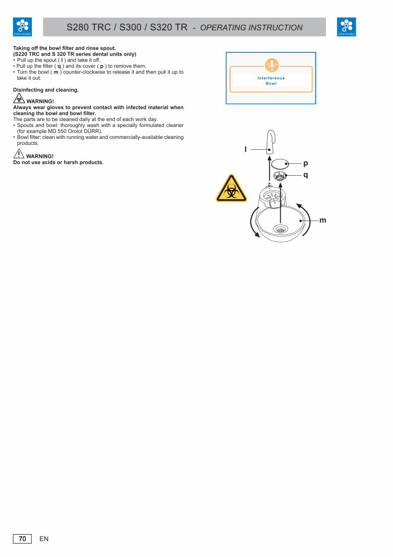
7070
�
�
�
�
����������������
S280 TRC / S300 / S320 TR - OPERATING INSTRUCTION
70 EN
Taking off the bowl filter and rinse spout.(S220 TRC and S 320 TR series dental units only)• Pull up the spout ( l )andtakeitoff.•Pullupthefilter(q ) and its cover ( p ) to remove them.• Turn the bowl ( m ) counter-clockwise to release it and then pull it up to
take it out.
Disinfecting and cleaning.
WARNING!Always wear gloves to prevent contact with infected material when cleaning the bowl and bowl filter.The parts are to be cleaned daily at the end of each work day.• Spouts and bowl: thoroughly wash with a specially formulated cleaner (forexampleMD550OrotolDÜRR).
•Bowlfilter:cleanwithrunningwaterandcommercially-availablecleaningproducts.
WARNING!Do not use acids or harsh products.

7171
� �
� �
S280 TRC / S300 / S320 TR - OPERATING INSTRUCTION
71EN
7.2 SANASPRAY System
Description of the systemThe SANASPRAY system is equipped with a distilled water tank ( a ). The tank can hold 1.8 liters.Distilled water is delivered to:• the sprays of all the instruments found on the instrument and assistant’s
board.• The syringe on the assistant’s board.•tofillthecup• water quick-connect coupler (if present)
The icon button on the TOUCH DISPLAY (see paragraph 5.1.1.2.8.) or the button on the assistant's board pushbutton panel allows to activate/deactivate the distilled water delivery.
NOTE: the distilled water delivery status is shown by the icon ( A ) on the control panel display.
Tank reserve level.Whentheliquidinthetankfallsbelowthereservelevel,therelativeicon( B ) appears on the instrument board’s console.
Filling the tank.Whenthewaterlevelinthetankislow(about500cc),fillitasdirectedbelow:• Disable the SANASPRAY system by touching the icon button or
pressing the button .Check that the icon ( B ) on the console display disappears.
NOTE: during this operation, the pressurized air contained in the tank will automatically be discharged to the outside.
• Turn the tank counter-clockwise ( a ) and remove it.•Pourdistilledwaterintothetankuntilthemaximumlevelisreached.
WARNING!Use only distilled water. For a higher guarantee of hygiene you can add 600 parts per million (ppm) of hydrogen peroxide using 20 ml of Peroxy Ag+ (not available for the American and Canadian markets) per litre of distilled water, or oxygenated water (20 ml of 3% oxygenated water per litre of distilled water).
• Put the tank back in place turning it clockwise.
WARNING!Make sure that the tank is properly tightened. • Touch the icon button or press the button to re-enable the SANASPRAYsystemandconfirmthatfillingiscomplete.Check that the icon ( A ) appears on the console display.
WARNING!If you are going to be absent from the surgery for long periods of time (holidays), completely empty out the tank ( a ) before leaving.
Cleaning the tank.We suggest cold-sterilizing periodically (at least once a month) only the tank with peracetic acid-based products (for American and Canadian markets we recommend using an EPA-approved product) in the following manner:• take the tank out of the dental unit and empty it:• prepare the solution of peracetic acid based product following the instruc-
tions provided by the manufacturer; •fillthetankuptotherimwiththeperaceticacidbasedproduct;• let the peracetic acid solution soak in the tank for the time stated by the
manufacturer;• empty the peracetic acid solution from the tank; • rinse the tank with distilled water; • fillthetankwithdistilledwaterand,ifnecessary,addhydrogenperoxideoroxygenatedwaterasdescribedabove;
• put the tank back in place in the dental unit.
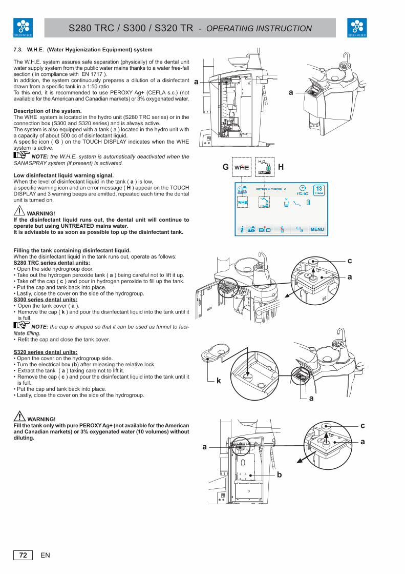
7272
��
� �
�
�
�
�
�
�
�
�
S280 TRC / S300 / S320 TR - OPERATING INSTRUCTION
72 EN
7.3. W.H.E. (Water Hygienization Equipment) system
The W.H.E. system assures safe separation (physically) of the dental unit water supply system from the public water mains thanks to a water free-fall section ( in compliance with EN 1717 ).Inaddition, thesystemcontinuouslypreparesadilutionofadisinfectantdrawnfromaspecifictankina1:50ratio.To thisend, it is recommended tousePEROXYAg+ (CEFLAs.c.) (notavailablefortheAmericanandCanadianmarkets)or3%oxygenatedwater.
Description of the system.The WHE system is located in the hydro unit (S280 TRC series) or in the connectionbox(S300andS320series)andisalwaysactive.The system is also equipped with a tank ( a ) located in the hydro unit with a capacity of about 500 cc of disinfectant liquid. Aspecific icon(G ) on the TOUCH DISPLAY indicates when the WHE system is active.
NOTE: the W.H.E. system is automatically deactivated when the SANASPRAY system (if present) is activated.
Low disinfectant liquid warning signal.When the level of disinfectant liquid in the tank ( a)islow,aspecificwarningiconandanerrormessage(H ) appear on the TOUCH DISPLAYand3warningbeepsareemitted,repeatedeachtimethedentalunit is turned on.
WARNING!If the disinfectant liquid runs out, the dental unit will continue to operate but using UNTREATED mains water.It is advisable to as soon as possible top up the disinfectant tank.
Filling the tank containing disinfectant liquid.Whenthedisinfectantliquidinthetankrunsout,operateasfollows:S280 TRC series dental units:• Open the side hydrogroup door.•Takeoutthehydrogenperoxidetank(a ) being careful not to lift it up.•Takeoffthecap(c)andpourinhydrogenperoxidetofillupthetank.• Put the cap and tank back into place.•Lastly,closethecoveronthesideofthehydrogroup.S300 series dental units:• Open the tank cover ( a ).• Remove the cap ( k ) and pour the disinfectant liquid into the tank until it
is full. NOTE: the cap is shaped so that it can be used as funnel to faci-
litate filling.• Refitthecapandclosethetankcover.
S320 series dental units:• Open the cover on the hydrogroup side.•Turntheelectricalbox(b) after releasing the relative lock.•Extractthetank(a ) taking care not to lift it.• Remove the cap ( c ) and pour the disinfectant liquid into the tank until it
is full.• Put the cap and tank back into place.•Lastly,closethecoveronthesideofthehydrogroup.
WARNING!Fill the tank only with pure PEROXY Ag+ (not available for the American and Canadian markets) or 3% oxygenated water (10 volumes) without diluting.

7373
S280 TRC / S300 / S320 TR - OPERATING INSTRUCTION
73EN
W.H.E. system water circuit drainage.ThisfunctionallowsdrainingthewatercircuitoftheW.H.E.systemifthedentalunitistoremainoffformanydays.The procedure for emptying the tank is given in paragraph 5.1.1.2.1.3.
Fault messages shown on the console display.Ifthesystemdetectsamalfunction,afaultmessageappearsonthedisplayscreen(seeparagraph11.).Ifthefaultfoundisminor,thedentalunitcontinuestooperate.Ontheotherhand,ifaseriousfaultisdetected,thedentalunitshutsdownanditisnecessary to call technical support.
PEROXY Ag+ storage.Forproperstorage,followthemanufacturer’sinstructionsprintedonthepackage.Itisimportanttokeepthepackagetightlyclosedandstoreitinacoolplaceatatemperaturenotexceeding25°C.
WARNING!Never leave PEROXY Ag+ or oxygenated water in the tank ( a ) for longer than one month.If you are going to be absent from the surgery for long periods of time (holidays), completely empty out the tank ( a ) before leaving.
NOTE: to empty the tank, it is advisable to use a suction cannula.
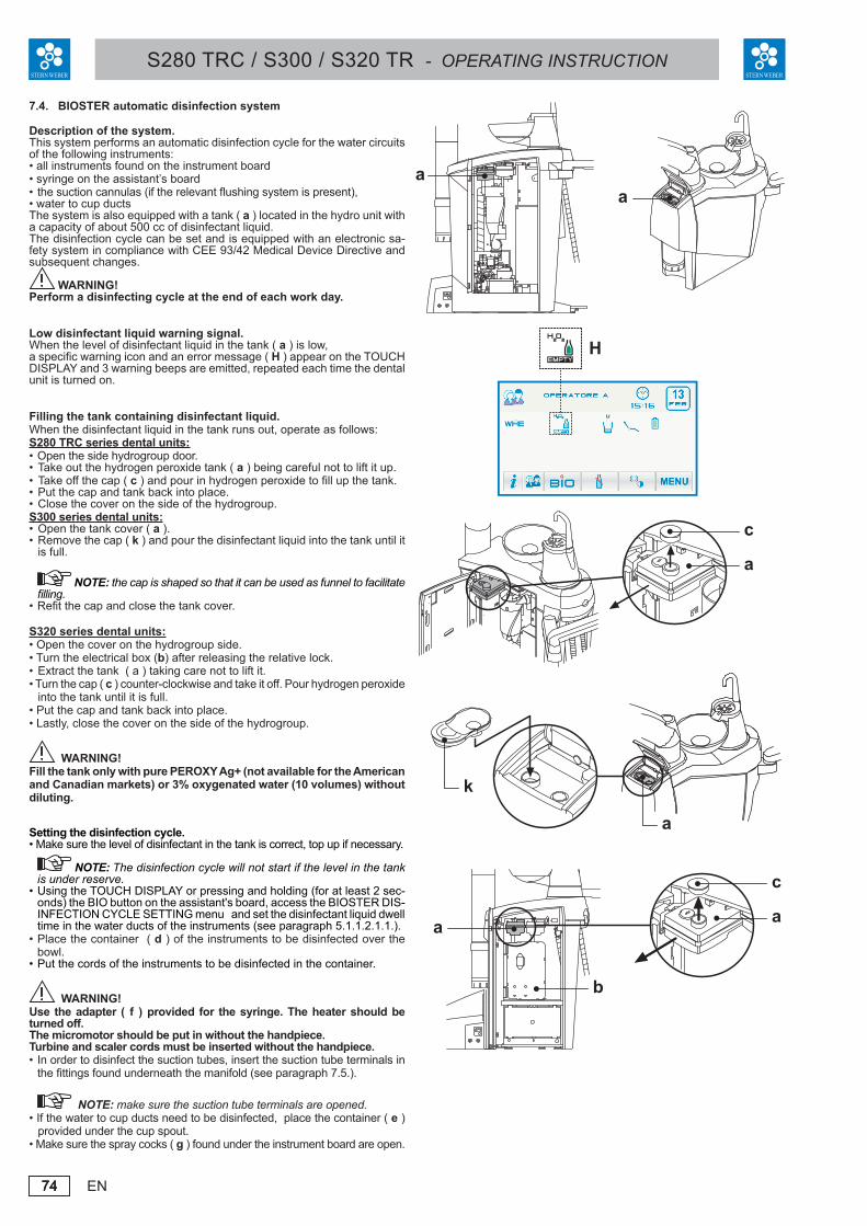
7474
�
��
�
�
�
�
�
�
�
�
S280 TRC / S300 / S320 TR - OPERATING INSTRUCTION
74 EN
7.4. BIOSTER automatic disinfection system
Description of the system.This system performs an automatic disinfection cycle for the water circuits of the following instruments:• all instruments found on the instrument board• syringe on the assistant’s board• thesuctioncannulas(iftherelevantflushingsystemispresent),• water to cup ductsThe system is also equipped with a tank ( a ) located in the hydro unit with a capacity of about 500 cc of disinfectant liquid. The disinfection cycle can be set and is equipped with an electronic sa-fetysystemincompliancewithCEE93/42MedicalDeviceDirectiveandsubsequent changes.
WARNING!Perform a disinfecting cycle at the end of each work day.
Low disinfectant liquid warning signal.When the level of disinfectant liquid in the tank ( a)islow,aspecificwarningiconandanerrormessage(H ) appear on the TOUCH DISPLAYand3warningbeepsareemitted,repeatedeachtimethedentalunit is turned on.
Filling the tank containing disinfectant liquid.Whenthedisinfectantliquidinthetankrunsout,operateasfollows:S280 TRC series dental units:• Open the side hydrogroup door.•Takeoutthehydrogenperoxidetank(a ) being careful not to lift it up.•Takeoffthecap(c)andpourinhydrogenperoxidetofillupthetank.• Put the cap and tank back into place.• Close the cover on the side of the hydrogroup.S300 series dental units:• Open the tank cover ( a ).• Remove the cap ( k ) and pour the disinfectant liquid into the tank until it
is full.
NOTE: the cap is shaped so that it can be used as funnel to facilitate filling.
•Refitthecapandclosethetankcover.
S320 series dental units:• Open the cover on the hydrogroup side.•Turntheelectricalbox(b) after releasing the relative lock.•Extractthetank(a)takingcarenottoliftit.• Turn the cap ( c)counter-clockwiseandtakeitoff.Pourhydrogenperoxide
into the tank until it is full.• Put the cap and tank back into place.•Lastly,closethecoveronthesideofthehydrogroup.
WARNING!Fill the tank only with pure PEROXY Ag+ (not available for the American and Canadian markets) or 3% oxygenated water (10 volumes) without diluting.
Setting the disinfection cycle.•Makesurethelevelofdisinfectantinthetankiscorrect,topupifnecessary.
NOTE: The disinfection cycle will not start if the level in the tank is under reserve.
• Using the TOUCH DISPLAY or pressing and holding (for at least 2 sec-onds)theBIObuttonontheassistant'sboard,accesstheBIOSTERDIS-INFECTION CYCLE SETTING menu and set the disinfectant liquid dwell time in the water ducts of the instruments (see paragraph 5.1.1.2.1.1.).
• Place the container ( d ) of the instruments to be disinfected over the bowl.
• Put the cords of the instruments to be disinfected in the container.
WARNING!Use the adapter ( f ) provided for the syringe. The heater should be turned off. The micromotor should be put in without the handpiece.Turbine and scaler cords must be inserted without the handpiece.• Inordertodisinfectthesuctiontubes,insertthesuctiontubeterminalsinthefittingsfoundunderneaththemanifold(seeparagraph7.5.).
NOTE: make sure the suction tube terminals are opened. •Ifthewatertocupductsneedtobedisinfected,placethecontainer( e )
provided under the cup spout.•Makesurethespraycocks(g ) found under the instrument board are open.
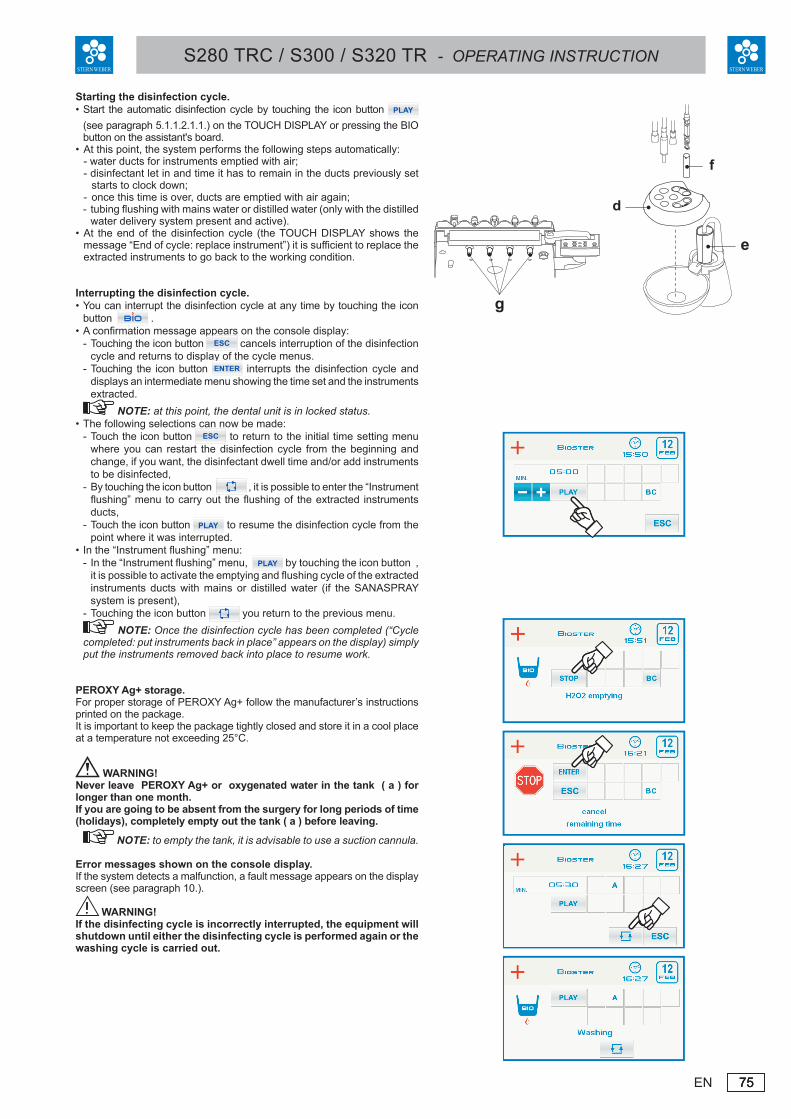
7575
�
�
�
�
S280 TRC / S300 / S320 TR - OPERATING INSTRUCTION
75EN
Starting the disinfection cycle.• Start the automatic disinfection cycle by touching the icon button
(see paragraph 5.1.1.2.1.1.) on the TOUCH DISPLAY or pressing the BIO button on the assistant's board.
•Atthispoint,thesystemperformsthefollowingstepsautomatically: - water ducts for instruments emptied with air; - disinfectant let in and time it has to remain in the ducts previously set
starts to clock down; - oncethistimeisover,ductsareemptiedwithairagain;- tubingflushingwithmainswaterordistilledwater(onlywiththedistilled
water delivery system present and active).• At the end of the disinfection cycle (the TOUCH DISPLAY shows the message“Endofcycle:replaceinstrument”)itissufficienttoreplacetheextractedinstrumentstogobacktotheworkingcondition.
Interrupting the disinfection cycle.• You can interrupt the disinfection cycle at any time by touching the icon
button .•Aconfirmationmessageappearsontheconsoledisplay:
- Touching the icon button cancels interruption of the disinfection cycle and returns to display of the cycle menus.
- Touching the icon button interrupts the disinfection cycle and displays an intermediate menu showing the time set and the instruments extracted.
NOTE: at this point, the dental unit is in locked status.• The following selections can now be made:
- Touch the icon button to return to the initial time setting menu where you can restart the disinfection cycle from the beginning and change,ifyouwant,thedisinfectantdwelltimeand/oraddinstrumentstobedisinfected,
- By touching the icon button ,itispossibletoenterthe“Instrumentflushing”menutocarryout theflushingof theextracted instrumentsducts,
- Touch the icon button to resume the disinfection cycle from the point where it was interrupted.
•Inthe“Instrumentflushing”menu:- Inthe“Instrumentflushing”menu, bytouchingtheiconbutton,itispossibletoactivatetheemptyingandflushingcycleoftheextractedinstruments ducts with mains or distilled water (if the SANASPRAY systemispresent),
- Touching the icon button you return to the previous menu. NOTE: Once the disinfection cycle has been completed (“Cycle
completed: put instruments back in place” appears on the display) simply put the instruments removed back into place to resume work.
PEROXY Ag+ storage.ForproperstorageofPEROXYAg+followthemanufacturer’sinstructionsprinted on the package. It is important to keep the package tightly closed and store it in a cool place atatemperaturenotexceeding25°C.
WARNING!Never leave PEROXY Ag+ or oxygenated water in the tank ( a ) for longer than one month.If you are going to be absent from the surgery for long periods of time (holidays), completely empty out the tank ( a ) before leaving.
NOTE: to empty the tank, it is advisable to use a suction cannula.
Error messages shown on the console display.Ifthesystemdetectsamalfunction,afaultmessageappearsonthedisplayscreen (see paragraph 10.).
WARNING!If the disinfecting cycle is incorrectly interrupted, the equipment will shutdown until either the disinfecting cycle is performed again or the washing cycle is carried out.
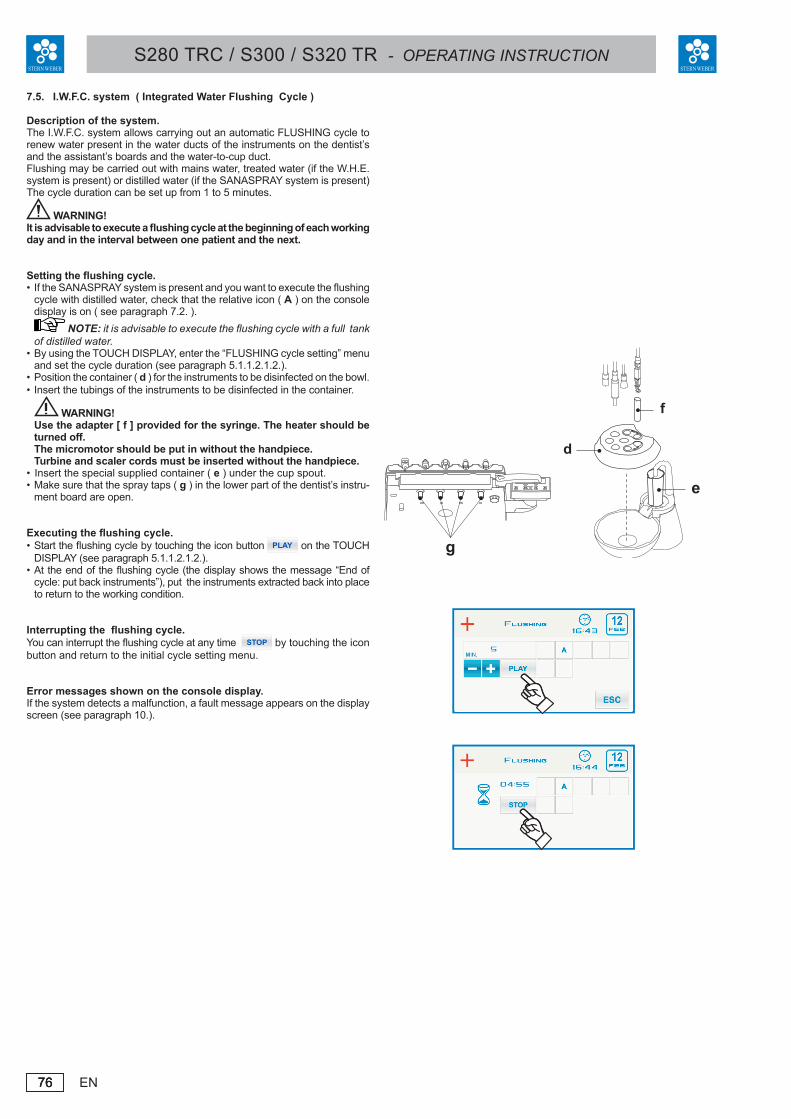
7676
�
�
�
�
S280 TRC / S300 / S320 TR - OPERATING INSTRUCTION
76 EN
7.5. I.W.F.C. system ( Integrated Water Flushing Cycle )
Description of the system.The I.W.F.C. system allows carrying out an automatic FLUSHING cycle to renew water present in the water ducts of the instruments on the dentist’s and the assistant’s boards and the water-to-cup duct.Flushingmaybecarriedoutwithmainswater,treatedwater(iftheW.H.E.system is present) or distilled water (if the SANASPRAY system is present)The cycle duration can be set up from 1 to 5 minutes.
WARNING!It is advisable to execute a flushing cycle at the beginning of each working day and in the interval between one patient and the next.
Setting the flushing cycle.• IftheSANASPRAYsystemispresentandyouwanttoexecutetheflushingcyclewithdistilledwater,checkthattherelativeicon(A ) on the console display is on ( see paragraph 7.2. ).
NOTE: it is advisable to execute the flushing cycle with a full tank of distilled water.
•ByusingtheTOUCHDISPLAY,enterthe“FLUSHINGcyclesetting”menuand set the cycle duration (see paragraph 5.1.1.2.1.2.).
• Position the container ( d ) for the instruments to be disinfected on the bowl. • Insert the tubings of the instruments to be disinfected in the container.
WARNING! Use the adapter [ f ] provided for the syringe. The heater should be
turned off. The micromotor should be put in without the handpiece. Turbine and scaler cords must be inserted without the handpiece.• Insert the special supplied container ( e ) under the cup spout.•Makesurethatthespraytaps(g ) in the lower part of the dentist’s instru-
ment board are open.
Executing the flushing cycle.• Starttheflushingcyclebytouchingtheiconbutton on the TOUCH
DISPLAY (see paragraph 5.1.1.2.1.2.). •Attheendoftheflushingcycle(thedisplayshowsthemessage“Endofcycle:putbackinstruments”),puttheinstrumentsextractedbackintoplaceto return to the working condition.
Interrupting the flushing cycle.Youcaninterrupttheflushingcycleatanytime by touching the icon button and return to the initial cycle setting menu.
Error messages shown on the console display.Ifthesystemdetectsamalfunction,afaultmessageappearsonthedisplayscreen (see paragraph 10.).
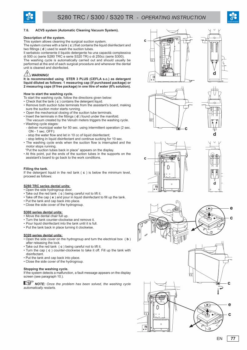
7777
�
��
�
�
�
�
�
�
�
�
S280 TRC / S300 / S320 TR - OPERATING INSTRUCTION
77EN
7.6. ACVS system (Automatic Cleaning Vacuum System).
Description of the system.This system allows cleaning the surgical suction system.The system comes with a tank ( c ) that contains the liquid disinfectant and twofittings(d ) used to wash the suction tubes.Il serbatoio contenente il liquido detergente ha una capacità complessiva di 500 cc (serie S280 TRC e serie S320 TR) o di 250cc (serie S300).The washing cycle is automatically carried out and should usually be performed at the end of each surgical procedure and whenever the dental unit is cleaned and disinfected.
WARNING!It is recommended using STER 3 PLUS (CEFLA s.c.) as detergent liquid diluted as follows: 1 measuring cap (if purchased package) or 2 measuring caps (if free package) in one litre of water (6% solution).
How to start the washing cycle.Tostartthewashingcycle,followthedirectionsgivenbelow:• Check that the tank ( c ) contains the detergent liquid.•Removebothsuctiontubeterminalsfromtheassistant’sboard,making
sure the suction motor starts running.• Open the mechanical closing of the suction tube terminals.•Inserttheterminalsinthefittings(d ) found under the manifold. The vacuum created by the Venutri meters triggers the washing cycle.• Washing cycle stages: - deliver municipal water for 50 sec. using intermittent operation (2 sec.
ON - 1 sec. OFF): -stopthewaterflowandletin10ccofliquiddisinfectant; - stop letting in liquid disinfectant and continue sucking for 10 sec.•Thewashingcycleendswhen thesuctionflow is interruptedand the
motor stops running. “Put the suction tubes back in place” appears on the display.•At thispoint,put theendsof thesuction tubes in thesupportson the
assistant’s board to go back to the work conditions.
Filling the tank.If the detergent liquid in the red tank ( c ) isbelow theminimum level,proceed as follows:
S280 TRC series dental units:• Open the side hydrogroup door.• Take out the red tank ( c ) being careful not to lift it. •Takeoffthecap(e)andpourinliquiddisinfectanttofillupthetank.• Put the tank and cap back into place. • Close the side cover of the hydrogroup.
S300 series dental units:•Movethedentalchairfullup.• Turn the tank counter-clockwise and remove it.• Pour liquid disinfectant into the tank until it is full.• Put the tank back in place turning it clockwise.
S320 series dental units:•Openthesidecoveronthehydrogroupandturntheelectricalbox(b )
after releasing the lock. • Take out the red tank ( c ) being careful not to lift it. • Turn the cap ( c)counter-clockwisetotakeitoff.Fillupthetankwith
disinfectant.• Put the tank and cap back into place. • Close the side cover of the hydrogroup.
Stopping the washing cycle.Ifthesystemdetectsamalfunction,afaultmessageappearsonthedisplayscreen (see paragraph 10.).
NOTE: Once the problem has been solved, the washing cycle automatically restarts.
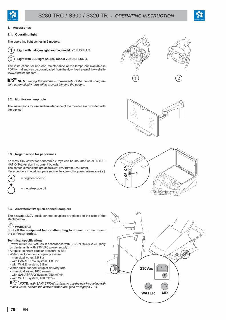
7878
��
�
�
��������
������
S280 TRC / S300 / S320 TR - OPERATING INSTRUCTION
78 EN
8.2. Monitor on lamp pole
The instructions for use and maintenance of the monitor are provided with the device.
8.3. Negatoscope for panoramas
Anx-rayfilmviewerforpanoramicx-rayscanbemountedonallINTER-NATIONAL version instrument boards. Thescreendimensionsareasfollows:H=210mm,L=300mm.Peraccendereilnegatoscopioèsufficienteagiresull'appositointerruttore(a ):
= negatoscope on
=negatoscopeoff
8.4. Air/water/230V quick-connect couplers
The air/water/230V quick-connect couplers are placed to the side of the electricalbox.
WARNING!Shut off the equipment before attempting to connect or disconnect the air/water outlets.
Technical specifications.• Power outlet: 230VAC 2A in accordance with IEC/EN 60320-2-2/F (only
on dental units with 230 VAC power supply).• Air quick-connect coupler pressure: 6 Bar.• Water quick-connect coupler pressure:
- municipalwater,2.5Bar- with SANASPRAYsystem,1,8Bar-withW.H.E.system,3Bar
• Water quick-connect coupler delivery rate:-municipalwater,1800ml/min- with SANASPRAY system,950ml/min-withW.H.E.system,400ml/min
NOTE: with SANASPRAY system: to use the quick-coupling with mains water, disable the distilled water tank (see Paragraph 7.2.).
8. Accessories
8.1. Operating light
The operating light comes in 2 models:
1 Light with halogen light source, model VENUS PLUS.
� Light with LED light source, model VENUS PLUS -L.
The instructions for use and maintenance of the lamps are available in PDF format and can be downloaded from the download area of the website www.sternweber.com.
NOTE: during the automatic movements of the dental chair, the light automatically turns off to prevent blinding the patient.
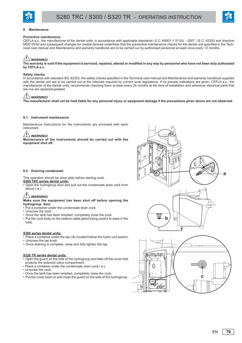
7979
�
�
�
S280 TRC / S300 / S320 TR - OPERATING INSTRUCTION
79EN
9. Maintenance
Preventive maintenance.CEFLAs.c.,themanufacturerofthedentalunits,inaccordancewithapplicablestandardsI.E.C. 60601-1 3rd Ed. - 2007 I.E.C. 62353 and directive MDD93/42andsubsequentchangesformedialdevicesunderlinesthatthepreventivemaintenancechecksforthedentalunitspecifiedintheTech-nicalcaremanualandMaintenanceandwarrantyhandbookaretobecarriedoutbyauthorisedpersonnelatleastonceevery12months.
WARNING!The warranty is void if the equipment is serviced, repaired, altered or modified in any way by personnel who have not been duly authorized by CEFLA s.c.
Safety checks.InaccordancewithstandardIEC62353,thesafetychecksspecifiedintheTechnicalcaremanualandMaintenanceandwarrantyhandbooksuppliedwiththedentalunitaretobecarriedoutattheintervalsrequiredbycurrentlocalregulations.Ifnopreciseindicationsaregiven,CEFLAs.c.,themanufacturerofthedentalunits,recommendscheckingthematleastevery24monthsatthetimeofinstallationandwheneverelectricalpartsthatare live are repaired/updated.
WARNING!The manufacturer shall not be held liable for any personal injury or equipment damage if the precautions given above are not observed.
9.1. Instrument maintenance
Maintenance instructions for the instruments are enclosedwith eachinstrument.
WARNING!Maintenance of the instruments should be carried out with the equipment shut off.
9.2. Draining condensate
This operation should be done daily before starting work.S280 TRC series dental units:• Open the hydrogroup door and pull out the condensate drain cock from
above ( a ).
WARNING!Make sure the equipment has been shut off before opening the hydrogroup door. • Put a container under the condensate drain cock.• Unscrew the cock.•Oncethetankhasbeenemptied,completelyclosethecock.• Put the cock body on the relative cable gland being careful to ease in the
tube.
S300 series dental units:• Place a container under the tap ( b ) located below the hydro unit section• Unscrew the tap knob•Oncedrainingiscomplete,closeandfullytightenthetap.
S320 TR series dental units:•Opentheguardonthesideofthehydrogroupandtakeoffthecoverthat
protects the solenoid valve compartment. • Place a container under the condensate drain cock ( c ).• Unscrew the cock.•Oncethetankhasbeenemptied,completelyclosethecock.• Put the cover back on and close the guard on the side of the hydrogroup.

8080
�
�
�
�
S280 TRC / S300 / S320 TR - OPERATING INSTRUCTION
80 EN
9.4. Surgical suction
The surgical suction system must be sanitized using a product suitable for this purpose.
WARNING!For cleaning of the suction system, it is recommended to use STER 3 PLUS (CEFLA s.c.) diluted in a 6% solution (equivalent to 60 ml of product in 1 litre of water).
At the end of each surgical procedure.•Executeanautomaticflushingcycleoraspirateabout½litreofsanitizing
solution with each of the cannulas used.• Sterilize the cannula holder terminals in steam autoclave (see paragraph
1.5.).
At the end of each work day.•Drawin1literofwaterwitheachsuctiontube,alternatingwaterandair
(keep the suction tube alternately in and out of the water).•Afterrinsingwithwater,executeanautomaticflushingcycleoraspirate
about ½ litre of sanitizing solution with each of the cannulas used.• Sterilize the cannula holder terminals in steam autoclave (see paragraph
1.5.).
WARNING!Whatever sanitizing product you use, follow the instructions given by the manufacturer.
NOTE: After these operations, it is advisable to aspirate only air in order to dry the entire suction system (5 minutes). Once a week.Remove the cannula body from its cord attachment and lubricate the O-rings ( o ) using S1-Protective Lubricant for O-Rings (CEFLA s.c.).
Once a year.Replace the suction tubes and ends of the tube holder.
9.3. Cleaning the surgical suction filter
This operation should be done daily at the end of work.
WARNING!Always wear gloves to prevent contact with infected material when cleaning the suction filters.
Proceed as follows:
S280 TRC / S300 series dental units:•Removethefilterdoor(e ) by pulling it up.•Takeoutthefiltersoneatatime(d ).
NOTE: the filter door can be used as a tray to carry them to the cleaning station.•Clean/replacethefilter(code97461845).•Putthefilterbackinplace.
WARNING!Before attempting to perform this operation, clean up any amalgam residues from the seat of each filter.
NOTE: To prevent liquids and matter from dripping from the filter taken out, perform the operations given above with the suction tube running.
S320 TR series dental units:•Takeoutthefilter(d ) one at a time.•Clean/replacethefilter(code97461845).•Putthefilterbackinplace.
WARNING!Remove any amalgam left at the seat of the filter before performing this operation.
NOTE: To prevent liquids and matter from dripping from the filter taken out, perform the operations given above with the suction tube running.
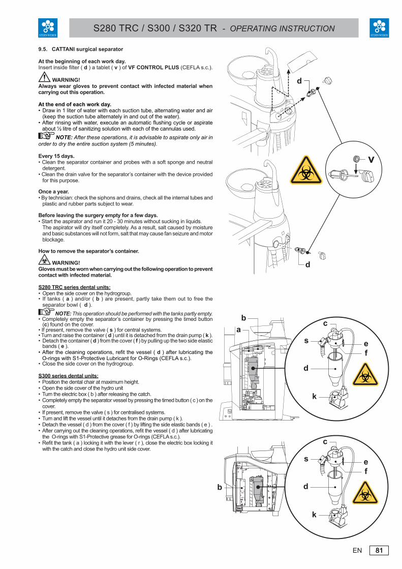
8181
��
�
�
�
�
�
�
�
�
�
�
�
�
�
�
�
�
S280 TRC / S300 / S320 TR - OPERATING INSTRUCTION
81EN
9.5. CATTANI surgical separator
At the beginning of each work day.Insertinsidefilter(d ) a tablet ( v ) of VF CONTROL PLUS (CEFLA s.c.).
WARNING!Always wear gloves to prevent contact with infected material when carrying out this operation.
At the end of each work day.•Drawin1literofwaterwitheachsuctiontube,alternatingwaterandair
(keep the suction tube alternately in and out of the water).•Afterrinsingwithwater,executeanautomaticflushingcycleoraspirate
about ½ litre of sanitizing solution with each of the cannulas used. NOTE: After these operations, it is advisable to aspirate only air in
order to dry the entire suction system (5 minutes).
Every 15 days.• Clean the separator container and probes with a soft sponge and neutral
detergent.• Clean the drain valve for the separator’s container with the device provided
for this purpose.
Once a year.•Bytechnician:checkthesiphonsanddrains,checkalltheinternaltubesandplasticandrubberpartssubjecttowear.
Before leaving the surgery empty for a few days.• Start the aspirator and run it 20 - 30 minutes without sucking in liquids. Theaspiratorwilldryitselfcompletely.Asaresult,saltcausedbymoistureandbasicsubstanceswillnotform,saltthatmaycausefanseizureandmotorblockage.
How to remove the separator’s container.
WARNING!Gloves must be worn when carrying out the following operation to prevent contact with infected material.
S280 TRC series dental units:• Open the side cover on the hydrogroup.• If tanks ( a ) and/or ( b )arepresent,partly takethemouttofreethe
separator bowl ( d ). NOTE: This operation should be performed with the tanks partly empty.
• Completely empty the separator’s container by pressing the timed button (c) found on the cover.
•Ifpresent,removethevalve(s ) for central systems.• Turn and raise the container ( d ) until it is detached from the drain pump ( k ).• Detach the container ( d ) from the cover ( f ) by pulling up the two side elastic
bands ( e ).•Afterthecleaningoperations,refitthevessel(d ) after lubricating the
O-rings with S1-Protective Lubricant for O-Rings (CEFLA s.c.).• Close the side cover on the hydrogroup.
S300 series dental units:•Positionthedentalchairatmaximumheight.• Open the side cover of the hydro unit•Turntheelectricbox(b)afterreleasingthecatch.• Completely empty the separator vessel by pressing the timed button ( c ) on the
cover.• Ifpresent,removethevalve(s)forcentralisedsystems.• Turn and lift the vessel until it detaches from the drain pump ( k ).• Detach the vessel ( d ) from the cover ( f ) by lifting the side elastic bands ( e ) .•Aftercarryingoutthecleaningoperations,refitthevessel(d)afterlubricating
the O-rings with S1-Protective grease for O-rings (CEFLA s.c.). •Refitthetank(a)lockingitwiththelever(r),closetheelectricboxlockingit
with the catch and close the hydro unit side cover.
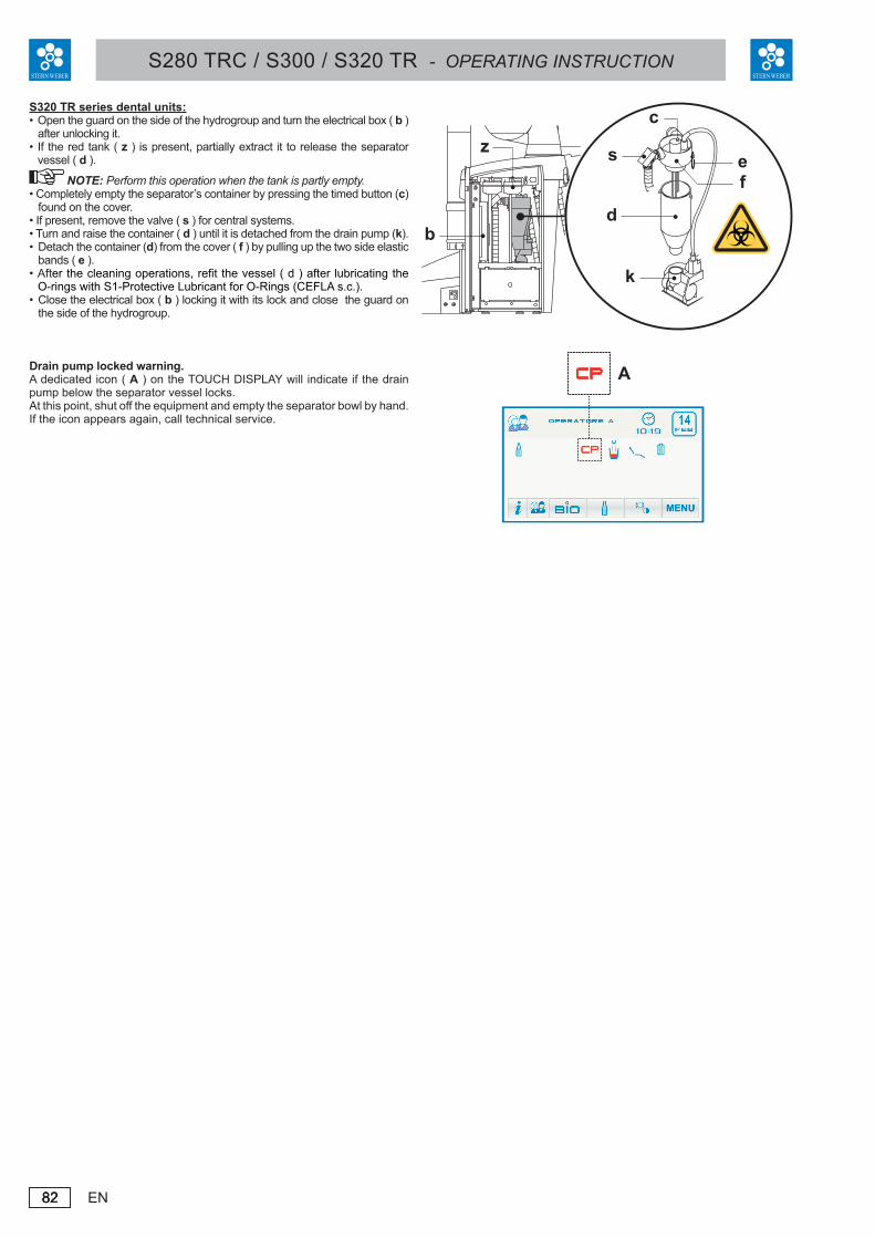
8282
�
�
��
�
�
�
�
�
S280 TRC / S300 / S320 TR - OPERATING INSTRUCTION
82 EN
S320 TR series dental units:•Opentheguardonthesideofthehydrogroupandturntheelectricalbox(b )
after unlocking it.• If the red tank ( z) ispresent,partiallyextractittoreleasetheseparator
vessel ( d ).
NOTE: Perform this operation when the tank is partly empty.• Completely empty the separator’s container by pressing the timed button (c)
found on the cover.•Ifpresent,removethevalve(s ) for central systems.• Turn and raise the container ( d ) until it is detached from the drain pump (k).• Detach the container (d) from the cover ( f ) by pulling up the two side elastic
bands ( e ).• Afterthecleaningoperations,refitthevessel(d)afterlubricatingthe
O-rings with S1-Protective Lubricant for O-Rings (CEFLA s.c.).•Closetheelectricalbox(b ) locking it with its lock and close the guard on
the side of the hydrogroup.
Drain pump locked warning.A dedicated icon ( A ) on the TOUCH DISPLAY will indicate if the drain pump below the separator vessel locks. Atthispoint,shutofftheequipmentandemptytheseparatorbowlbyhand.Iftheiconappearsagain,calltechnicalservice.
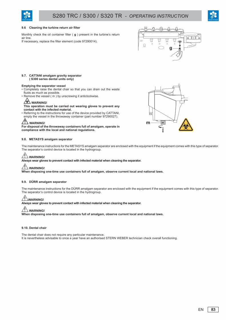
8383
�
�
S280 TRC / S300 / S320 TR - OPERATING INSTRUCTION
83EN
9.6 Cleaning the turbine return air filter
Monthlychecktheoilcontainerfilter(g ) present in the turbine’s return air line. Ifnecessary,replacethefilterelement(code97290014).
9.7. CATTANI amalgam gravity separator ( S300 series dental units only)
Emptying the separator vessel• Completely raise the dental chair so that you can drain out the waste fluidsasmuchaspossible.
• Remove the vessel ( m ) by unscrewing it anticlockwise.
WARNING!This operation must be carried out wearing gloves to prevent any contact with the infected material.
•ReferringtotheinstructionsforuseofthedeviceprovidedbyCATTANI,empty the vessel in the throwaway container (part number 97290027).
WARNING!For disposal of the throwaway containers full of amalgam, operate in compliance with the local and national regulations.
9.8. METASYS amalgam separator
ThemaintenanceinstructionsfortheMETASYSamalgamseparatorareenclosedwiththeequipmentiftheequipmentcomeswiththistypeofseparator.The separator’s control device is located in the hydrogroup.
WARNING!Always wear gloves to prevent contact with infected material when cleaning the separator.
WARNING!When disposing one-time use containers full of amalgam, observe current local and national laws.
9.9. DÜRR amalgam separator
ThemaintenanceinstructionsfortheDÜRRamalgamseparatorareenclosedwiththeequipmentiftheequipmentcomeswiththistypeofseparator.The separator’s control device is located in the hydrogroup.
WARNING!Always wear gloves to prevent contact with infected material when cleaning the separator.
WARNING!When disposing one-time use containers full of amalgam, observe current local and national laws.
9.10. Dental chair
The dental chair does not require any particular maintenance. It is nevertheless advisable to once a year have an authorised STERN WEBER technician check overall functioning.
8484
S280 TRC / S300 / S320 TR - OPERATING INSTRUCTION
84 EN
10. Fault messages
M =MessageshownonconsoledisplayC = CauseR = Remedy
M: “H2O level low, fill tank”C: The water in the independent water system's tank has dropped below
the minimum acceptable level.R: Fill the tank (see paragraph 7.2.).
M: “Put instruments back in place”C: The system detected an instrument was already withdrawn while the
disinfecting cycle was being set. R: Makesurealltheinstrumentsareinplaceandthensetthecycleagain.
Ifthefaultmessageappearsagain,calltechnicalsupport.
M: “Check instruments, repeat cycle”C: The system detected the withdrawn instruments were altered during
theflushingordisinfectingcycle.R: Check the selected instruments and repeat the disinfecting (see
paragraph7.4.)orflushing(seeparagraph7.5.)cycle.
M: “H2O2 level low, fill tank”C: Thehydrogenperoxideintherelativetankhasdroppedbelowthe
minimum acceptable level.R: Fillthehydrogenperoxidetank(seeparagraph7.4.).
M: “Open H2O spray cocks”C: Thesystemisnotabletofillthelineswithhydrogenperoxideduring
the disinfecting cycle. R: Open the water spray cocks and repeat the disinfecting cycle (see
paragraph7.4.).Ifthemessageappearsagain,calltechnicalsupport.
M: “Remove all instruments”C: The system detected an internal malfunction during the disinfecting
cycle. R: Repeat thedisinfectingcycle,selectingall the instruments. If the
messageappearsagain,calltechnicalsupport.
M: “Empty WHE system”C: WHE system malfunction.R: Empty the tank inside the WHE system and restart the system (see
paragraph5.1.1.2.1.3.).Ifthemessageappearsagain,calltechnicalsupport.
M: “Turn on WHE”C: The system is attempting to perform a task which requires that the
WHE system is turned on. R: Turn on the WHE system (see paragraph 7.3.).
M: “Check suction tubes, repeat cycle”C: The system has detected that the suction tubes are not connected to
therelativefittingsduringtheflushingordisinfectingcycle.R: Makesurethesuctiontubesareproperlyconnectedandrepeatthe
disinfecting(seeparagraph7.4.)orflushing(seeparagraph7.5.)cycle.Ifthemessageappearsagain,calltechnicalsupport.
M: “Withdraw at least one instrument”C: An attempt has been made to start a disinfecting cycle without selecting
any instruments or the cup. R: Repeat the disinfecting cycle selecting at least one instrument or the
cup.Ifthemessageappearsagain,calltechnicalsupport.
M: “Instrument configured”C: The instrument in the indicated position on the board has been auto-
maticallyconfiguredwiththefactorysettings.R: Ifthemessageappearsagain,calltechnicalsupport.
M: “Put suction tubes back in place”C: Suctiontubesextractedwhendentalunitisturnedon.R: Makesurethesuctiontubesarecorrectlyplacedintheirhousings.If
themessageappearsagain,calltechnicalsupport.
M: “Put instrument back in place”C: Instrumentextractedwhendentalunitisturnedon.R: Makesurealltheinstrumentsarecorrectlyplacedintheirhousings.
Ifthemessageappearsagain,calltechnicalsupport.
M: “Check suction tube filter”C: Suctiontubeflushingcyclemalfunction.R: Makesurethefiltersareclean,thesuctiontubesarenotclosedand
thatthesuctionunitworkscorrectlyandthenrepeattheflushingcycle.Ifthemessageappearsagain,calltechnicalsupport.
M: “Hydrogroup emergency device activated”C: While performinganautomaticmovement, the assistant's board
encountered an obstacle. R: Clear the obstacle and press the button for the desired program again.
M: “Lower dental chair”C: The bowl does not move because the dental chair is in its way. R: Lower the dental chair so that it is no longer in the way.
M: “Check operating light fuses”C: The operating light does not turn on because electric power is not
supplied. R: Call technical support.
M: “Maintenance required"C: Scheduled maintenance required.R: Call technical support to schedule the maintenance work.
M: “Footboard emergency device activated”C: The dental chair encountered an obstacle.R: Pressthe"seatup"buttonandcleartheobstacle.
M: “Backrest emergency device activated”C: The dental chair backrest encountered an obstacle.R: Pressthe"seatup"buttonandcleartheobstacle.
M: “Move bowl”C: The dental chair does not move because the bowl is in the way. R: Movethebowlsothatitisnolongerinthewayofthedentalchair.
M: “Seat emergency device activated”C: The dental chair encountered an obstacle.R: Pressthe"seatup"buttonandcleartheobstacle.
M: “Delivery emergency device activated”C: The side delivery board encountered an obstacle.R: Pressthedentalchair"seatup"buttonandcleartheobstacle.
M: “Dental chair blocked, put instrument back in place”C: An attempt was made to move the dental chair with an instrument
withdrawn.R: Put instrument back in place and repeat dental chair movement.
M: “Dental chair blocked”C: An attempt was made to move the dental chair while it was blocked R: Remove dental chair blockage (see paragraph 4.).
IMPORTANT INFORMATION!M: “XXXX, call technical support” (where XXXX represents a nume-
rical code)C: This type of message indicated a serious internal error. R: Call technical support quoting the number of the error.
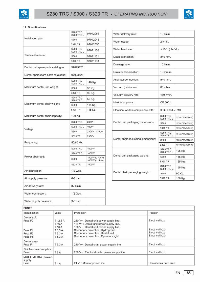
8585
S280 TRC / S300 / S320 TR - OPERATING INSTRUCTION
85EN
FUSESIdentification Value Protection Position
Dental unit.Fuse F2
Fuse F4Fuse F5Fuse F6
T12,5AT 16 AT 16 AT6,3AT6,3AT6,3A
230 V~ : Dental unit power supply line.115 V~ : Dental unit power supply line.100 V~ : Dental unit power supply line.Secondary protection: Hydrogroup.Secondary protection: Dental unit.Secondary protection: Operatory light.
Electricalbox.
Electricalbox.Electricalbox.Electricalbox.
Dental chair.Fuse F1 T6,3A 230 V~ : Dental chair power supply line. Electricalbox.
Quick-connect couplers.Fuse T 2 A 230 V~ : Electrical outlet power supply line. Electricalbox.
MULTIMEDIA powersupply.Fuse T 4 A 21V~:Monitorpowerline. Dental chair card area.
Installation plan:
S280 TRCS280 TRC J 97042066
S300 97042045
S320 TR 97042055
Technical manual:
S280 TRCS280 TRC J 97071160
S300 97071161
S320 TR 97071163
Dental unit spare parts catalogue: 97023126
Dental chair spare parts catalogue: 97023126
Maximumdentalunitweight:
S280 TRCS280 TRC J 140 Kg.
S300 90 Kg.
S320 TR 90 Kg.
Maximumdentalchairweight:
S280 TRCS280 TRC J 50 Kg.
S300 115 Kg.
S320 TR 115 Kg.
Maximumdentalchaircapacity: 190 Kg.
Voltage:
S280 TRC 230V~
S280 TRC J 100V~
S300 230V~ / 115V~
S320 TR 230V~
Frequency: 50/60 Hz.
Power absorbed:
S280 TRC 1500W
S280 TRC J 1000W
S300 1500W (230V~)1000W (115V~)
S320 TR 1500W
Air connection: 1/2 Gas.
Air supply pressure: 6-8 bar.
Air delivery rate: 82 l/min.
Water connection: 1/2 Gas.
Water supply pressure: 3-5 bar.
Water delivery rate: 10 l/min
Water usage: 2 l/min.
Water hardness: < 25 °f ( 14 °d )
Drain connection: ø40 mm.
Drainage rate: 10 l/min.
Drain duct inclination: 10 mm/m.
Aspirator connection: ø40 mm.
Vacuum (minimum): 65 mbar.
Vacuum delivery rate: 450 l/min.
Markofapproval: CE 0051
Electrical work in compliance with: IEC 60364-7-710
Dental unit packaging dimensions:
S280 TRCS280 TRC J 1570x780x1500(h)
S300 1570x780x1325(h)
S320 TR 1570x780x1495(h)
Dental chair packaging dimensions:
S280 TRCS280 TRC J 1510x730x1000(h)
S300 1520x730x1030(h)
S320 TR 1510x730x1000(h)
Dental unit packaging weight:
S280 TRCS280 TRC J 195 Kg.
S300 135 Kg.
S320 TR 155 Kg.
Dental chair packaging weight:
S280 TRCS280 TRC J 195 Kg.
S300 90 Kg.
S320 TR 100 Kg.
11. Specifications
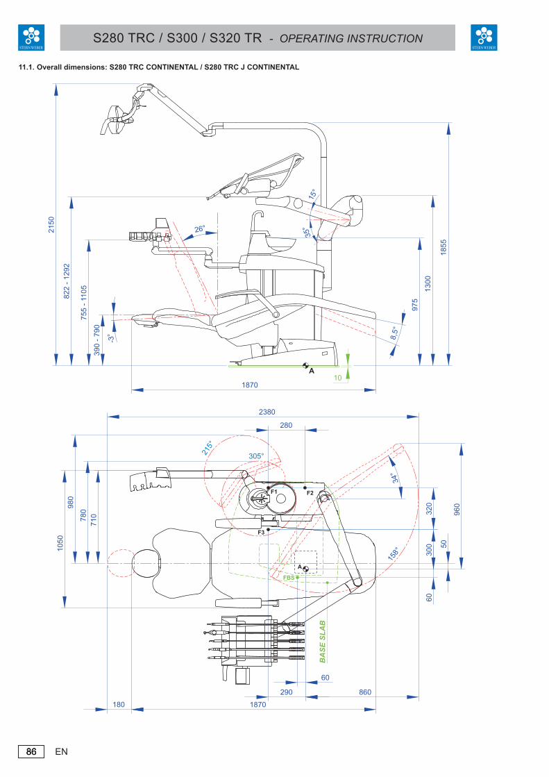
8686
����
����
���
���
���
���
���
����
����
�
������
��
��
����
����
��
����
����
��
����
������
���
���
����
���
��
����
����
�� ��
���
��
�
����
���
���
���
��� ����
���
��
����
���
�
���
���
����
S280 TRC / S300 / S320 TR - OPERATING INSTRUCTION
86 EN
11.1. Overall dimensions: S280 TRC CONTINENTAL / S280 TRC J CONTINENTAL
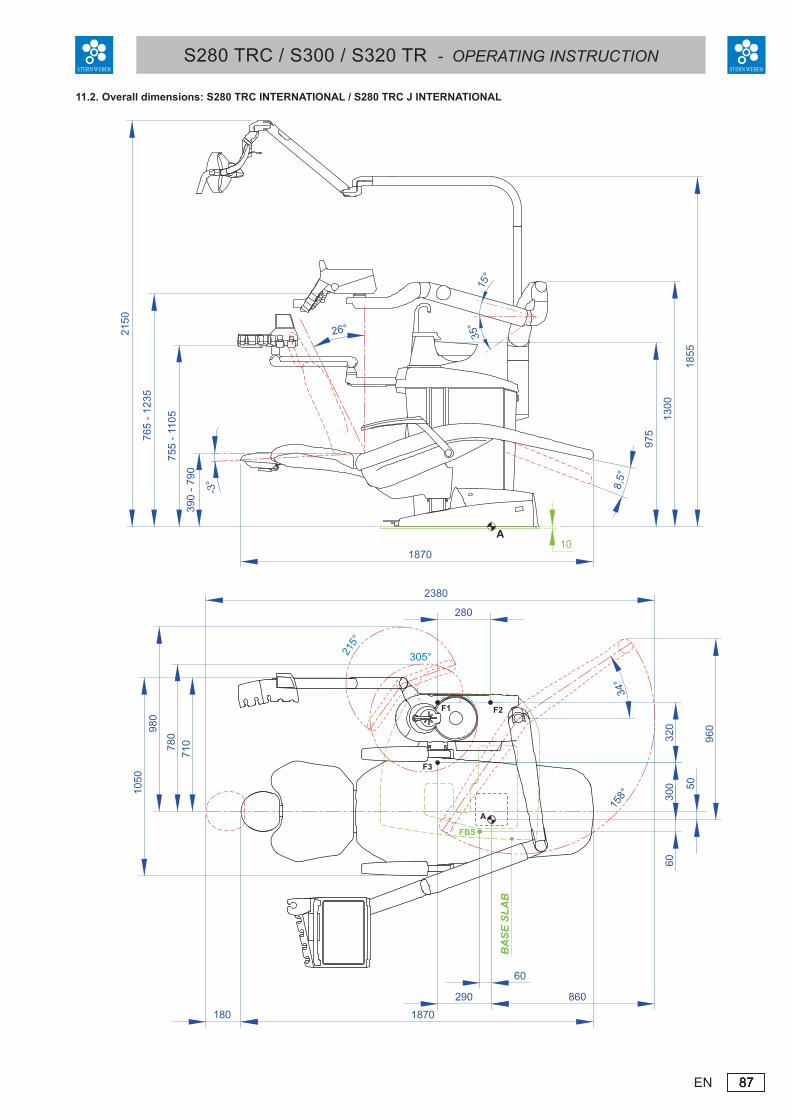
8787
����
����
���
���
���
���
���
����
����
�
����
����
��
����
����
��
����
����
��
����
������
���
���
����
���
��
����
����
�� ��
���
��
�
����
���
���
���
��� ����
���
��
����
���
�
���
���
����
S280 TRC / S300 / S320 TR - OPERATING INSTRUCTION
87EN
11.2. Overall dimensions: S280 TRC INTERNATIONAL / S280 TRC J INTERNATIONAL
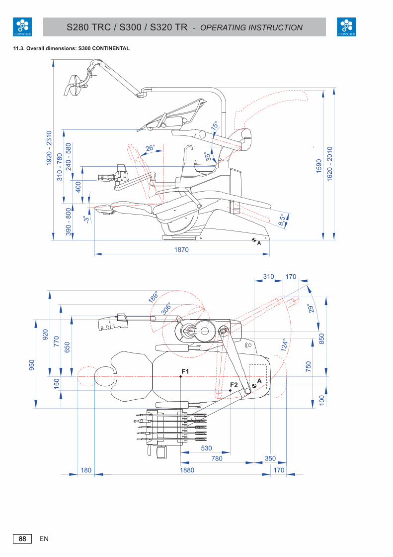
8888
���
����
���
���
���
���
���� ���
���
���
��� ���
���
���
���
���
���
���
����
����
���
��
���
����
����
���
����
����
���
������
�
����
����
����
����
���
����
���
���
���
����
����
���
�
S280 TRC / S300 / S320 TR - OPERATING INSTRUCTION
88 EN
11.3. Overall dimensions: S300 CONTINENTAL
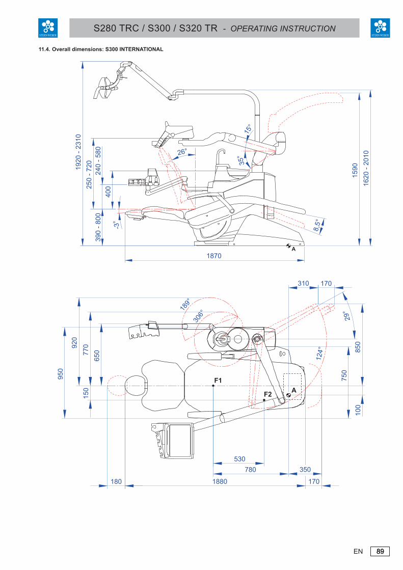
8989
���
����
����
���
����
����
���
������
�
����
����
����
����
���
����
���
���
���
����
����
���
�
���
����
���
���
���
���
���� ���
���
���
��� ���
���
���
���
���
���
���
����
����
���
��
S280 TRC / S300 / S320 TR - OPERATING INSTRUCTION
89EN
11.4. Overall dimensions: S300 INTERNATIONAL
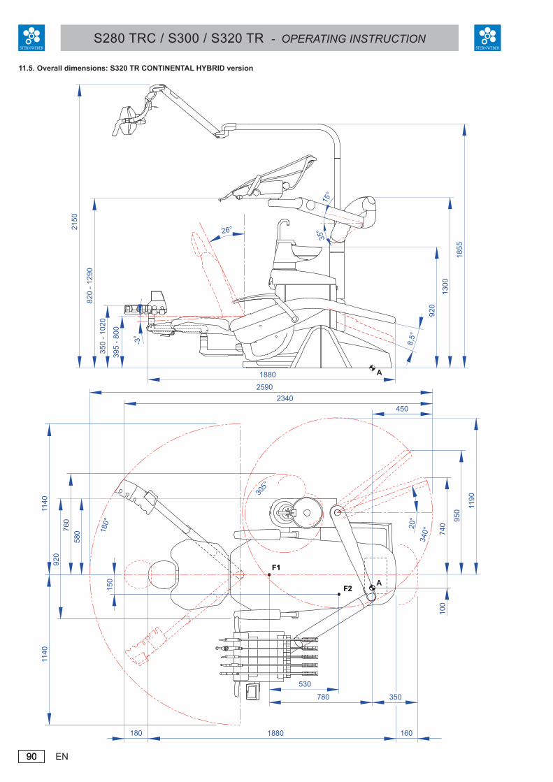
9090
�
���
����
����
����
���
����
����
����
�
����
����
��
����
����
��
����
���
���
���
�
S280 TRC / S300 / S320 TR - OPERATING INSTRUCTION
90 EN
11.5. Overall dimensions: S320 TR CONTINENTAL HYBRID version
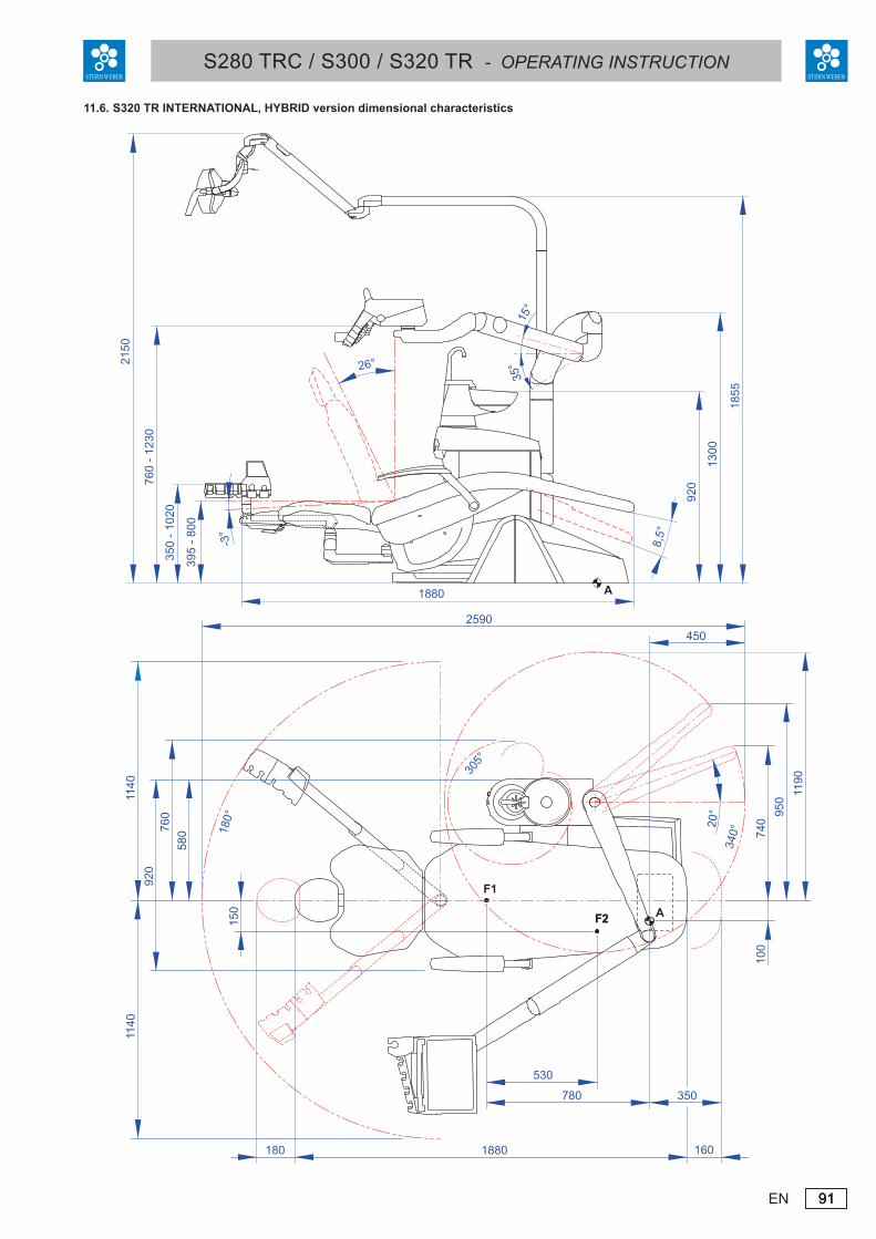
9191
�
���
����
����
����
���
����
����
����
�
����
����
��
����
����
��
����
���
���
���
�
S280 TRC / S300 / S320 TR - OPERATING INSTRUCTION
91EN
11.6. S320 TR INTERNATIONAL, HYBRID version dimensional characteristics

9292
S280 TRC / S300 / S320 TR - OPERATING INSTRUCTION
92 EN
12. Dental operatory maintenance planWHEN PART HOW SEE PARAGRAPH
Before starting work.Drain condensate. / See paragraph 9.2
CATTANI suction separator. InsertinsideeachsuctionfilteratabletofVFCONTROL PLUS. See paragraph 9.5.
After each treatment.
Contra angle handpiece. Sterilize or disinfect the outside. See documentation enclosed with handpiece
Turbine. Sterilize or disinfect the outside. See paragraph 5.4
Micromotor. Disinfect outside. See paragraph 5.5
Scaler. Sterilize or disinfect outside. See paragraph 5.6
Syringe. Sterilize or disinfect outside. See paragraph 5.3
Curing lamp. Sterilizefiberoptic,disinfectoutside. See paragraph 5.7
C-U2 camera. Disinfect outside.Do not use acids or harsh products. See paragraph 5.8
Surgical suction tubes.Aspirate about ½ litre of sanitizing solution with each cannula.Sterilize the cannula holder terminals.
See paragraph 9.4
When needed.
Bowl.Cleanwithoff-shelfdetergentsformulatedforceramic materialsDo not use acids or harsh products.
See paragraph 7.1
METASYSsurgicalseparator. Seedocumentationenclosedwithequipment, /
DURR surgical separator. Seedocumentationenclosedwithequipment, /
Operatory light. Seedocumentationenclosedwithequipment, /
Monitorwithlightpole. Seedocumentationenclosedwithequipment, /
Removable instrument cords.Clean with a suitable disinfectant carefully following the directions for use provided by the manufacturer. Do not use acids or harsh products.
See paragraph 5
Coated surfaces and dental chair upholstery.
Clean with a suitable disinfectant carefully following the directions for use provided by the manufacturer. Do not use acids or harsh products.
See paragraph 1.4
At the end of the work day.
Bowlfilter. CleanfilterinrunningwaterThe content must be disposed of separately See paragraph 7.1
Surgicalsuctionfilter. Checkthefilterandreplaceitifthesuctionrateis reduced (code 97461845). See paragraph 9.3
Surgical suction tubes. Cleanthefilterofthesalivaejectorterminal. See paragraph 9.4
Hydraulicsalivaejector. Cleanthefilterofthesalivaejectorterminal. See paragraph 6.6
Weekly.CATTANI surgical separator. Clean theseparator’scontainer,drainvalve
and probes. See paragraph 9.5
Cannula holder terminals. Lubricate the O-rings. See paragraph 9.4
Monthly. Turbinereturnairfilter. Check the filter and replace it if necessary(code 97290014). See paragraph 9.6
Yearly. Dental chair. Contact the technical service department for general inspection. /

CEFLA s.c. Via Selice Prov.le 23/a – 40026 Imola (BO) Italy P. Iva/Vat It 00499791200 – C.F. 00293150371 Reg. Imprese n. 5089/BO – R.E.A. n.36186/BO www.cefla.it – [email protected]
Stabilimento / Plant Via Bicocca 14/c – 40026 Imola (BO) Italy Tel. (+39) 0542 653441 – Fax (+39) 0542 653555 www.cefladentale.it - [email protected]
Mod. 97010019 - Rev.5 30/07/2015
DICHIARAZIONE DI CONFORMITÀ “CE / EU” / “CE / EU” CONFORMITY DECLARATION DECLARATION DE CONFORMITÉ “CE / EU” / ERKLÄRUNG VON “CE / EU” ZUSTIMMUNG / DECLARACION DE CONFORMIDAD “CE / EU”
DECLARAÇÃO DE CONFORMIDADE “CE / EU“ / ΙΤΟΤΤΑ “CE / EU” / ДЕКЛАРАЦИЯ СООТВЕТСТВИЯ “CE / EU” DEKLARACJA ZGODNOSCI WE “CE / EU” / ‘’CE / EU’’ UYGUNLUK BELGESİ
Prodotto tipo/ Product type :
Incollare in questo spazio l'etichetta del complesso odontoiatrico o di altra apparecchiatura o indicare
modello e numero di matricola Stick the label of the dental equipment or other device
into this space or write model and serial number
Matr./ Serial N°:
I Dichiariamo sotto la nostra esclusiva responsabilità che i prodotti ai quali questa dichiarazione si riferisce sono conformi 1) ai requisiti essenziali (Allegato I) presenti nella direttiva 93/42/CEE Dispositivi Medici (D.Lgs.46/97) e successive modifiche ed integrazioni (dispositivo
medico di Classe IIa) 2) alla direttiva 2011/65/UE del Parlamento europeo e del Consiglio dell’8 giugno 2011, sulla restrizione dell’uso di determinate sostanze pericolose nelle
apparecchiature elettriche ed elettroniche (Rohs 2) GB We declare, on our sole responsibility, that the products referred to herein are in compliance with 1) the essential requirements (Annexe I) of Directive 93/42/EEC Medical devices (Leg. Decree 46/97) and subsequent amendments and integrations
(Class IIa medical device) 2) Directive 2011/65/EU of the European Parliament and of the Council of 8 June 2011 on the restriction of the use of certain hazardous substances in
electrical and electronic equipment (Rohs 2) F Nous déclarons, sous notre complète responsabilité, que les produits auxquels la présente déclaration fait référence sont conformes 1) aux exigences essentielles (Annexe I) présentes dans la directive 93/42/CEE "Dispositifs médicaux" (Décr.L. 46/97) et modifications successives et
intégrations (dispositif médical de Classe IIa) 2) à la directive 2011/65/UE du Parlement européen et du Conseil du 8 juin 2011 relative à la limitation de l’utilisation de certaines substances dangereuses
dans les équipements électriques et électroniques (Rohs 2) D Wir erklären hiermit in alleiniger Verantwortung, dass die Produkte, auf die sich diese Erklärung bezieht, konform sind mit 1) den grundlegenden Anforderungen (Anhang I) der Richtlinie 93/42/EWG über Medizinprodukte (Gesetzesverordnung 46/97) und nachfolgenden
Änderungen und Ergänzungen (medizinisches Gerät der Klasse IIa) 2) der Richtlinie 2011/65/EU des Europäischen Parlaments und des Rats vom 8. Juni 2011 zur Beschränkung der Verwendung bestimmter gefährlicher
Stoffe in Elektro- und Elektronikgeräten (Rohs 2) E Declaramos bajo nuestra exclusiva responsabilidad que los productos a los que esta declaración se refiere, están conformes con 1) los requisitos esenciales (Anexo I) presentes en la directiva 93/42/CEE Dispositivos Médicos (D. Leg. 46/97) y sucesivas modificaciones e integraciones
(dispositivo médico de Clase IIa) 2) la directiva 2011/65/UE del Parlamento europeo y del Consejo del día 8 de junio de 2011, sobre la restricción del uso de determinadas sustancias
peligrosas en los aparatos eléctricos y electrónicos (Rohs 2) P Declaramos sob a nossa exclusiva responsabilidade que os produtos aos quais esta declaração se refere estão em conformidade 1) com os requisitos essenciais (Anexo I) presentes na diretiva 93/42/CEE Dispositivos Médicos (em Itália, transposta pelo Decreto Legislativo 46/97) e
posteriores alterações e aditamentos (dispositivo médico de Classe IIa) 2) com a diretiva 2011/65/UE do Parlamento europeu e do Conselho de 8 de junho de 2011, relativa à restrição do uso de determinadas substâncias
perigosas em equipamentos elétricos e eletrónicos (Rohs 2) GR Δηλώνουμε με την αποκλειστική ευθύνη μας ότι τα προϊόντα στα οποία αναφέρεται η παρούσα δήλωση είναι σύμφωνα 1) με τις βασικές απαιτήσεις (Προσάρτημα I) της οδηγίας 93/42/ΕΟΚ Ιατροτεχνολογικών Προϊόντων (Ν. Διάτ.46/97) και μεταγενέστερες τροποποιήσεις και
συμπληρώσεις (ιατροτεχνολογικό προϊόν Κατηγορίας IIa) 2) με την οδηγία 2011/65/ΕΕ του Ευρωκοινοβουλίου και του Συμβουλίου της 8 Ιουνίου 2011, για τον περιορισμό της χρήσης ορισμένων επικίνδυνων
ουσιών σε ηλεκτρικό και ηλεκτρονικό εξοπλισμό (Rohs 2) PY Под нашу исключительную ответственность заявляем, что изделия, к которым относится данная декларация, соответствуют 1) основным требованиям (Приложение I) директивы 93/42/ЕЭС Медицинские устройства (Законодательный указ № 46/97) и последующим
изменениям и дополнениям (медицинское устройство Класса IIa) 2) директиве 2011/65/ЕС Европарламента и Совета Европы от 8 июня 2011 года по ограничению использования определенных опасных веществ
в электрическом и электронном оборудовании (Rohs 2) PL Oświadczamy na swoją wyłączną odpowiedzialność, że produkty objęte niniejszym oświadczeniem są zgodne: 1) z zasadniczymi wymaganiami (Załącznik I) przewidzianymi dyrektywą 93/42/EWG Wyroby Medyczne (D. z mocą ustawy 46/97) wraz z późniejszymi
zmianami i uzupełnieniami (wyrób medyczny Klasa IIa) 2) z dyrektywą 2011/65/WE Parlamentu europejskiego i Rady z dnia 8 czerwca 2011r. w sprawie ograniczeń we wprowadzaniu do obrotu i stosowaniu w
sprzęcie elektrycznym i elektronicznym określonych niebezpiecznych substancji (Rohs 2) TR Bu beyannamede bahsi geçen ürünlerin aşağıda belirtilenlere uygun olduğunu kendi münhasır sorumluluğumuz altında beyan ederiz: 1) (Kanun hükmünde Kararname 46/97) Medikal Aygıtlar 93/42/CEE direktifinde mevcut (Ek 1) ana gereklilikler ve sonraki değişiklikler ve eklemelerde
belirtilenler (IIa sınıf medikal aygıt) 2) 8 Haziran 2011 tarihli Avrupa Parlamentosu ve Konseyi’nin “Elektrikli ve elektronik cihazlarda bazı tehlikeli maddelerin kullanılmasına ilişkin kısıtlamalar”
2011/65/UE direktifi (Rohs 2) Imola, lì____________________________ Bussolari Paolo
Managing Director
Related Documents


![Finale 2006 - [S280 Glory to God Brass BEV]cuthbertpraise.com/files/S280_SCORE.pdfGlory to God (Brass Ensemble Version) S280 Canticle 20 ©2006 CuthbertPraise! #S280 Episcopal Hymnal](https://static.cupdf.com/doc/110x72/60056d6ed54e1c4229237c69/finale-2006-s280-glory-to-god-brass-bev-glory-to-god-brass-ensemble-version.jpg)