Smart Sensors Presenting a New Laser-type ZX-LDA@-N Amplifier Unit The Continuing Evolution of Smart Sensors ZX Series

Welcome message from author
This document is posted to help you gain knowledge. Please leave a comment to let me know what you think about it! Share it to your friends and learn new things together.
Transcript
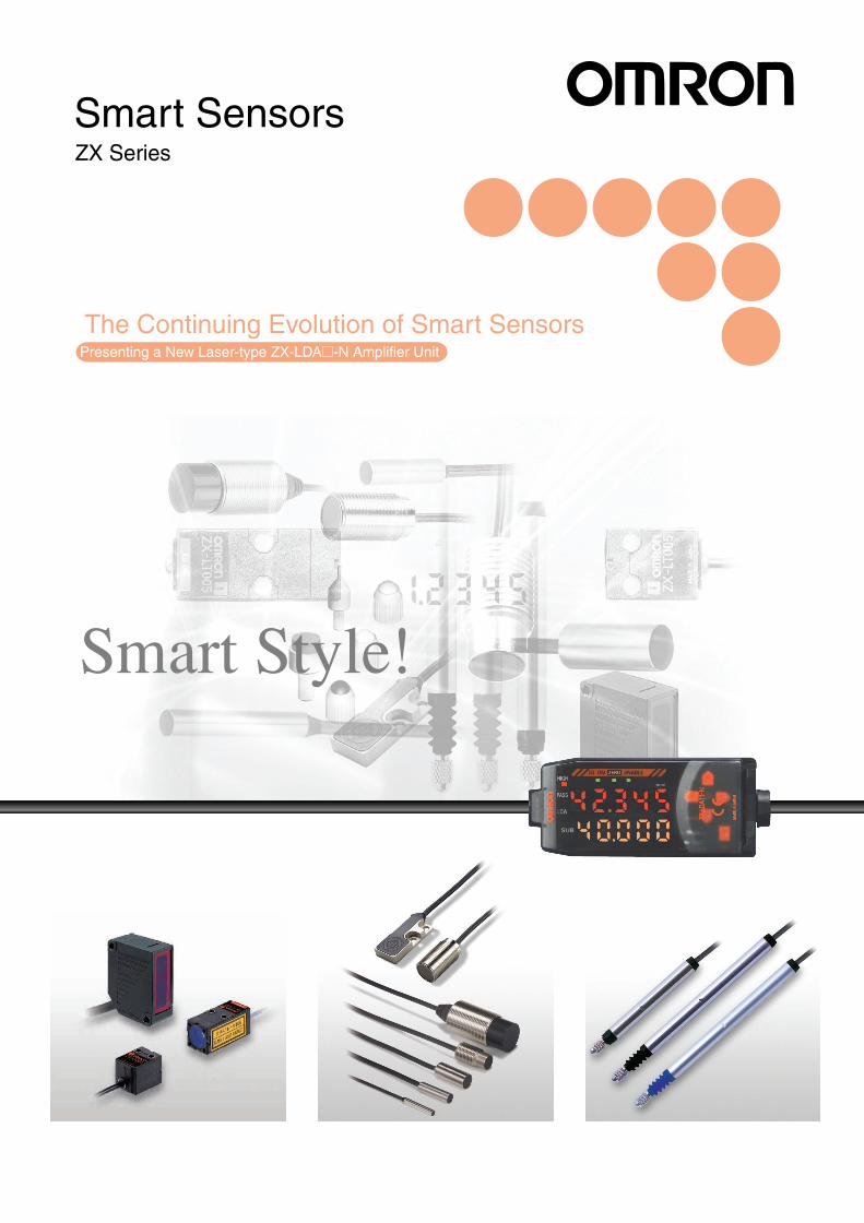
Smart Sensors
Presenting a New Laser-type ZX-LDA@-N Amplifier Unit
The Continuing Evolution of Smart Sensors
ZX Series

Easy-to-see Resolution
Deviation to be detected
30 mm
31 mm
64 mm Amplifier
What's Style?
Top Priority Placed on Easy Operation
Arrow keys improve operating control
7-mm-high LED charactersDigital dual displayDisplays distance and thresholdvalues at power ON.
Advanced functions and performance plus easy operation.This is a major feature of the ZX Series.Experience operation that doesn't get any easier.
Judgement output indicatorHigh/Pass/Low 3-color display
The resolution of the desired workpiece can also be easilydetermined by detection. The resolution display clearly shows themargin available for the threshold setting, to allow accuratejudgement of detectability.
Patent Pending
Position/2-point/Automatic
Comprehensive Teaching Functions
Three teaching functions rival the performance of photoelectricsensors.
Position teachingFor high-precision positioning applications
2-point teachingFor detecting ultra-small level differences between two points
Automatic teachingFor teaching without stopping the workpiece
A Full Complement of Practical FunctionsOperating Setting with No Need fora Digital Panel Meter
Calculating UnitT=K−(A+B)
Reso-lution
Patent Pending
What'sSmart?
A host of remarkable functions inside acompact body. OMRON combined thesewith an Amplifier display and easy operationto take Sensor detection to a whole newlevel. OMRON's sensing platform meets awide range of diverse applications byoffering a broad selection of headsemploying different detection methods.
ZX
0302
T=K-(A+B)
Sensingplatform
Diffuse reflective
Regular reflective
Throughbeam
Screw-shaped
Cylindrical
Flat
Heat-resistive
Short
Standard
Low-measurement
Digital dual display
Measurement
Threshold setting
Amplifier Sensor Head Application
Laser Sensors
Inductive DisplacementSensors
High-precisionContact Sensors
Small object inclination detectionand workpiece height measurement
Thickness detection andwarp/level difference detection
Surface movement/eccentricitydetection and thin objectdetection
Counting printed materialsand continuous measurement
Detecting small differences inlevel
Solder level detection insoldering tanks
Multiple-point level differencedetection
A
B
C
D
E
F
G
Smart Style... from OMRON
OMRON Offers Sensor Users New Choices
I am a Smart Sensor !!
What's the Platform?The ZX-LD-N integrates internal data for the entire ZXSeries. This was achieved through technologicaladvancements that vastly improve data communicationsbetween Amplifiers and enable calculations betweendifferent Sensor Heads.Welcome to the ever-expanding Smart World of sensing.
Laser Sensors
Inductive DisplacementSensors
High-precision ContactSensors
By simply fitting a Calculating Unit between two Amplifiers, theprocessing results of two Sensors can be displayed on a singleAmplifier. Setting parameters need to be input only on oneAmplifier.
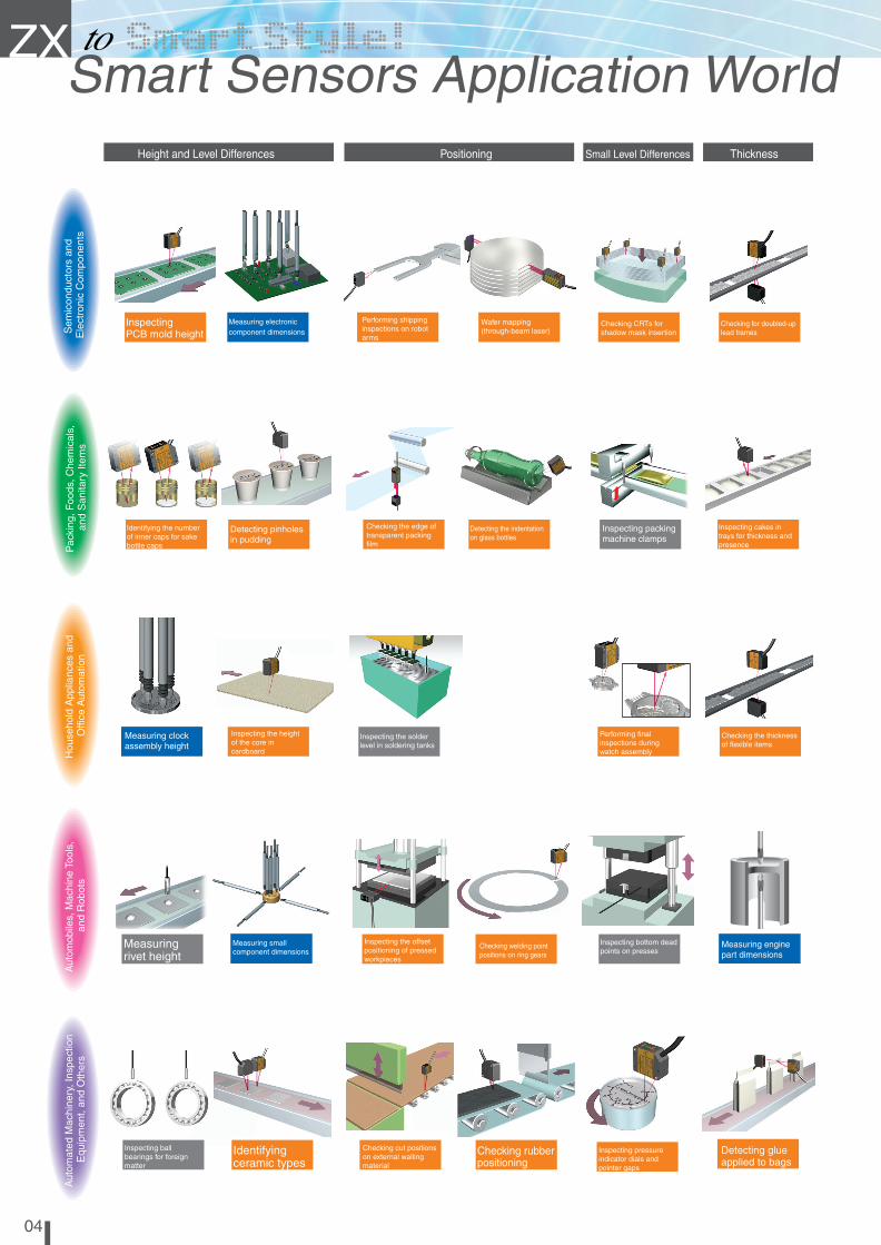
Height and Level Differences Positioning Small Level Differences Thickness
ZXSmart Sensors Application World ZX-LDA ZX-EDA ZX-TDA
0504
InspectingPCB mold height
Identifyingceramic types
Checking rubberpositioning
Detecting glueapplied to bags
Measuring electroniccomponent dimensions
Performing shippinginspections on robotarms
Wafer mapping(through-beam laser)
Checking CRTs forshadow mask insertion
Checking for doubled-uplead frames
Identifying the numberof inner caps for sakebottle caps
Detecting pinholesin pudding
Checking the edge oftransparent packingfilm
Detecting the indentationon glass bottles
Inspecting packingmachine clamps
Inspecting cakes intrays for thickness andpresence
Measuring clockassembly height
Inspecting the heightof the core incardboard
Inspecting the solderlevel in soldering tanks
Performing finalinspections duringwatch assembly
Checking the thicknessof flexible items
Measuringrivet height
Measuring smallcomponent dimensions
Inspecting the offsetpositioning of pressedworkpieces
Checking welding pointpositions on ring gears
Inspecting bottom deadpoints on presses
Measuring enginepart dimensions
Inspecting ballbearings for foreignmatter
Checking cut positionson external wallingmaterial
Inspecting pressureindicator dials andpointer gaps
Sem
icon
duct
ors
and
Ele
ctro
nic
Com
pone
nts
Pac
king
,Foo
ds,C
hem
ical
s,an
dS
anita
ryIte
ms
Hou
seho
ldA
pplia
nces
and
Offi
ceA
utom
atio
nA
utom
obile
s,M
achi
neTo
ols,
and
Rob
ots
Aut
omat
edM
achi
nery
,Ins
pect
ion
Equ
ipm
ent,
and
Oth
ers
Counting teabags
Detecting raisedcaps
Checking diesfor fit
Countingenvelops
Measuringroller gap
Width and Level Differences
Sem
icon
duct
ors
and
Ele
ctro
nic
Com
pone
nts
Pac
king
,Foo
ds,C
hem
ical
s,an
dS
anita
ryIte
ms
Hou
seho
ldA
pplia
nces
and
Offi
ceA
utom
atio
nA
utom
obile
s,M
achi
neTo
ols,
and
Rob
ots
Aut
omat
edM
achi
nery
,Ins
pect
ion
Equ
ipm
ent,
and
Oth
ers
Warp and Raised Items Eccentricity, Surface Movement,Coating Thickness
Inspecting robotarms for flatness
Checking disc motortables for surfacemovement
Inspecting chips forproper arrangement
Identifyingcapacitor types
Checking the flatnessof battery caps
Detecting bonding agentand quantity duringpacking box assembly
Checking the edge oftransparent packing film
Counting copy machinestaples and pins
Checking the flatness ofHDD chassis
Inspecting the sprayfrom aerosol cans
Measuring warpageof HDD chassis
Countingcontainers
Checking the flatness ofbrake pads
Measuring machinetool eccentricity andvibration
Inspecting drivebelt thickness
Inspecting steelplate surface areas
Inspecting theeccentricity of motorshafts
Inspecting seat beltsfor loose threads
Inspecting papertube length
Flatness Counting

ZX
Import
Export
0706
New Sensor Proposals for IT Applications
Smart Monitor V3
Flexible Quality ControlData logging
PC Connection Takes Full Advantageof Sensor Performance
The ability to log detection data and manage the system historyenables efficient and effective quality control, and aides indetermining necessary countermeasures. Also displays data inwaveform during logging.
Waveforms on up to 5channels can be drawn withthe new ZX-LDA-N.
High-speed waveforms canbe obtained and displayedin one-shot operation.
Use of the PC screen greatly enhances the panel display. Unlikeconventional systems, the detection results from applications suchas waveform monitoring and data logging can also be easilyprocessed.
List Display Simplifies SetupComplicated settings can be easily made with only the Amplifierpanel while referring to function menus. Settings can also beimported and exported as text data.
The screen image may differ from that of the actual product.
Head Amplifier
Interface Unit
Waveform Monitoring
Waveform monitoring
Easy waveform monitoring replaces the conventionaloscilloscope. Drag & drop threshold setting and other easy-to-use functions further enhance operation.
One-shot waveform
PC Software SpecificationsMonitoring Digital Values Setting differential direct threshold values Teaching settings
Waveform Monitoring Waveform collection Waveform observation Waveform saving and loading
Data Logging Compilation settings Microsoft Excel compatible (See note 2.)
Configurator Functions Setting Amplifier functions
(actual measurement scaling, input scaling, etc.) Saving and loading Amplifier setting conditionsNote 1: Smart Monitor V3 is compatible with the ZX-L-N, ZX-L, ZX-E, and ZX-T.
Note 2: Microsoft Excel is a registered trademark of the Microsoft Corporation.
Note 3: System Requirements
OS: Windows 98 or 2000
CPU Unit: Celeron 400 MHz or better
RAM: 64 MB min.
Available hard disk space: 50 MB min.
Display screen: 800 x 600 dots and 256 colors min.
Baud rate: 38,400 bps min.
Note 4: Use an RS-232C crossover cable to connect to the computer.If the computer does not have an RS-232C port, use a USB-Serial Conversion Cable(CS1W-CF31 made by OMRON).
N E W
Contents
ZX-LDA-N Laser Sensors 8
ZX-EDA Inductive Displacement Sensors 18
ZX-TDA High-precision Contact Sensors 28
Datasheet 12
Common Precautions 35
Datasheet 20
Datasheet 30
ZX
0908
ZX-LDA-N
15 mm
34 mm15 mm
15 mm
15 mm19 mm
Through-beam
Sensors
Light-receiving side
Light-emitting side
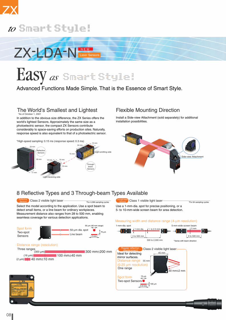
Advanced Functions Made Simple. That is the Essence of Smart Style.
Flexible Mounting DirectionThe World's Smallest and Lightest*As of October 1, 2001
*High-speed sampling: 0.15 ms (response speed: 0.3 ms)
ReflectiveSensors
N E WZX-LDA-N
8 Reflective Types and 3 Through-beam Types Available
Distance range (resolution)
Spot form
Three ranges
Two-spotSensors
50-µm dia. spot
Line beam
40 mm±10 mm100 mm±40 mm
300 mm±200 mm(300 µm)(16 µm)
(2 µm)
50 µm (40 mm range)
Class 2 visible light laser*For 4,096 sampling cycles
ReflectiveSensors
Distance range(0.25 µm resolution)One range
30 mm±2 mm
Ideal for detectingmirror surfaces.
Regular reflection(displacement)
45 mm
55 mm
Measuring width and distance range (4-µm resolution)
Class 1 visible light laser*For 64 sampling cycles
Through-beamSensors
1-mm-dia. spot
0 to 500 mm
500 to 2,000 mm
1-mm dia. 1- to 2.5-mm
5-mm-wide screen beam
0 to 500 mm
*Varies with beam direction
Install a Side-view Attachment (sold separately) for additionalinstallation possibilities.
Laser Sensors
In addition to the obvious size difference, the ZX Series offers theworld's lightest Sensors. Approximately the same size as aphotoelectric sensor, the compact ZX Sensors contributeconsiderably to space-saving efforts on production sites. Naturally,response speed is also equivalent to that of a photoelectric sensor.
Select the model according to the application. Use a spot beam todetect small items, or a line beam for ordinary workpieces.Measurement distance also ranges from 28 to 500 mm, enablingseamless coverage for various detection applications.
Use a 1-mm-dia. spot for precise positioning, or a5- to 10-mm-wide screen beam for area detection.
Class 2 visible light laser
Spot formTwo-spot Sensors
75 µm
1.8 mm100 µm
Side-view Attachment39 mm
17 mm
33 mm
5 mm
Counting connector pins
Light-intensity Mode: High-performance Laser Photoelectric SensorLight intensity can be detected by the ultra-small spot of the laser beam. By operating as a high-precision laser photoelectric sensor, rather than a displacement meter, this enables detection of smallitems with backgrounds, as well as color detection. Ideal function settings are possible by using boththe displacement mode and the light-intensity mode to meet multiple application needs.
Displacement mode Light-intensity mode
Distance display Received light display
ReflectiveSensors
Through-beamSensors
Light-intensity Mode: High-performanceLaser Photoelectric Sensor
Equipped with a Laser Lifetime MonitorSelf-detection and Display of Laser Diode LifetimeWhen laser diode deterioration is detected, a warning appears on the sub-digital display. Early detection enables timely, trouble-free replacement.
Light-intensity mode/% mode
Measurement-widthmode
Light-receiving display/transmittance display
Measurement-widthmode75 µm
2 mm

ZX
0908
ZX-LDA-N
15 mm
34 mm15 mm
15 mm
15 mm19 mm
Through-beam
Sensors
Light-receiving side
Light-emitting side
Advanced Functions Made Simple. That is the Essence of Smart Style.
Flexible Mounting DirectionThe World's Smallest and Lightest*As of October 1, 2001
*High-speed sampling: 0.15 ms (response speed: 0.3 ms)
ReflectiveSensors
N E WZX-LDA-N
8 Reflective Types and 3 Through-beam Types Available
Distance range (resolution)
Spot form
Three ranges
Two-spotSensors
50-µm dia. spot
Line beam
40 mm±10 mm100 mm±40 mm
300 mm±200 mm(300 µm)(16 µm)
(2 µm)
50 µm (40 mm range)
Class 2 visible light laser*For 4,096 sampling cycles
ReflectiveSensors
Distance range(0.25 µm resolution)One range
30 mm±2 mm
Ideal for detectingmirror surfaces.
Regular reflection(displacement)
45 mm
55 mm
Measuring width and distance range (4-µm resolution)
Class 1 visible light laser*For 64 sampling cycles
Through-beamSensors
1-mm-dia. spot
0 to 500 mm
500 to 2,000 mm
1-mm dia. 1- to 2.5-mm
5-mm-wide screen beam
0 to 500 mm
*Varies with beam direction
Install a Side-view Attachment (sold separately) for additionalinstallation possibilities.
Laser Sensors
In addition to the obvious size difference, the ZX Series offers theworld's lightest Sensors. Approximately the same size as aphotoelectric sensor, the compact ZX Sensors contributeconsiderably to space-saving efforts on production sites. Naturally,response speed is also equivalent to that of a photoelectric sensor.
Select the model according to the application. Use a spot beam todetect small items, or a line beam for ordinary workpieces.Measurement distance also ranges from 28 to 500 mm, enablingseamless coverage for various detection applications.
Use a 1-mm-dia. spot for precise positioning, or a5- to 10-mm-wide screen beam for area detection.
Class 2 visible light laser
Spot formTwo-spot Sensors
75 µm
1.8 mm100 µm
Side-view Attachment39 mm
17 mm
33 mm
5 mm
Counting connector pins
Light-intensity Mode: High-performance Laser Photoelectric SensorLight intensity can be detected by the ultra-small spot of the laser beam. By operating as a high-precision laser photoelectric sensor, rather than a displacement meter, this enables detection of smallitems with backgrounds, as well as color detection. Ideal function settings are possible by using boththe displacement mode and the light-intensity mode to meet multiple application needs.
Displacement mode Light-intensity mode
Distance display Received light display
ReflectiveSensors
Through-beamSensors
Light-intensity Mode: High-performanceLaser Photoelectric Sensor
Equipped with a Laser Lifetime MonitorSelf-detection and Display of Laser Diode LifetimeWhen laser diode deterioration is detected, a warning appears on the sub-digital display. Early detection enables timely, trouble-free replacement.
Light-intensity mode/% mode
Measurement-widthmode
Light-receiving display/transmittance display
Measurement-widthmode75 µm
2 mm
ZX
N E W
New Function
New FunctionEnhanced Hold Function
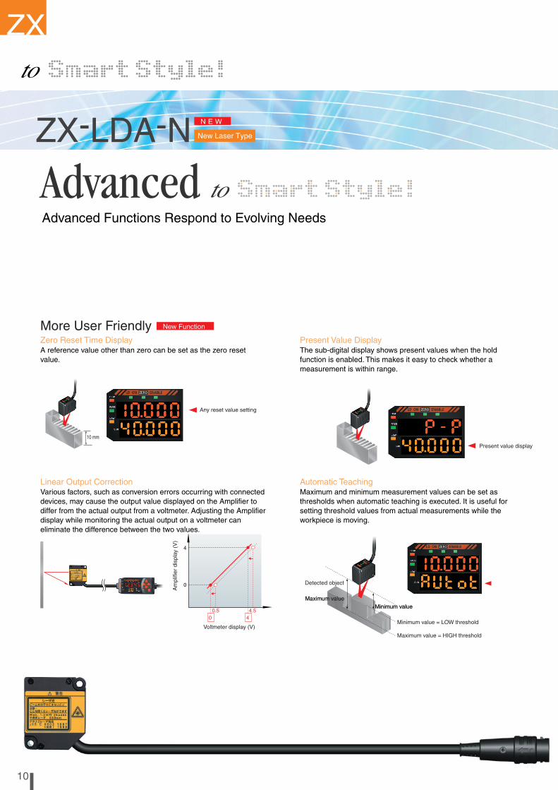
More User Friendly
10 mm
Zero Reset Time Display Delay Hold/Average Hold
Multiple-point Measurements Computed Using 1 Point
Present Value Display
Automatic TeachingLinear Output Correction
Any reset value setting
Present value display
T1 T2
Self-triggering levelAverage for T2
Time
Displacement
Average hold and delay hold functions were added to enableaccurate assessment of changes and the desired measurementposition.
The delay hold function measures only signals within thedesired sampling time after a specified time delay from thetrigger. The newly added average hold function is especiallyuseful for measuring large workpieces with uneven surfaces.
The result computed for one point can be used as a basis for the output for every otherpoint. This is especially useful for multiple-point measurements.
ZX-LDA-N
ZX-LDA-N
1110
Delay time Sampling time
Average hold
Previous Value Comparison FunctionGradual changes in measurements due to machinetemperature changes or other factors can be ignored incertain situations, such as when detecting foreign matteraround bearings. The previous value comparison functioneffectively detects any changes between previous andpresent values.
1
L thresholdL threshold
12
2 2
3
33
3
4
4
5
5
6
Time
Displacement
Self-triggering levelSelf-triggering level
A reference value other than zero can be set as the zero resetvalue.
The sub-digital display shows present values when the holdfunction is enabled. This makes it easy to check whether ameasurement is within range.
Maximum and minimum measurement values can be set asthresholds when automatic teaching is executed. It is useful forsetting threshold values from actual measurements while theworkpiece is moving.
Various factors, such as conversion errors occurring with connecteddevices, may cause the output value displayed on the Amplifier todiffer from the actual output from a voltmeter. Adjusting the Amplifierdisplay while monitoring the actual output on a voltmeter caneliminate the difference between the two values.
Am
plifi
erdi
spla
y(V
)
Voltmeter display (V)
0.5 4.50
0
4
4
Detected object
Minimum value = LOW threshold
Maximum value = HIGH threshold
Maximum valueMinimum value
Maximum valueMinimum value
1 ch1 ch
2 ch
3 ch4 ch
2 ch-1 ch
3 ch-1 ch
4 ch-1 ch
Advanced Functions Respond to Evolving Needs
New Laser Type

ZX
N E W
New Function
New FunctionEnhanced Hold Function
More User Friendly
10 mm
Zero Reset Time Display Delay Hold/Average Hold
Multiple-point Measurements Computed Using 1 Point
Present Value Display
Automatic TeachingLinear Output Correction
Any reset value setting
Present value display
T1 T2
Self-triggering levelAverage for T2
Time
Displacement
Average hold and delay hold functions were added to enableaccurate assessment of changes and the desired measurementposition.
The delay hold function measures only signals within thedesired sampling time after a specified time delay from thetrigger. The newly added average hold function is especiallyuseful for measuring large workpieces with uneven surfaces.
The result computed for one point can be used as a basis for the output for every otherpoint. This is especially useful for multiple-point measurements.
ZX-LDA-N
ZX-LDA-N
1110
Delay time Sampling time
Average hold
Previous Value Comparison FunctionGradual changes in measurements due to machinetemperature changes or other factors can be ignored incertain situations, such as when detecting foreign matteraround bearings. The previous value comparison functioneffectively detects any changes between previous andpresent values.
1
L thresholdL threshold
12
2 2
3
33
3
4
4
5
5
6
Time
Displacement
Self-triggering levelSelf-triggering level
A reference value other than zero can be set as the zero resetvalue.
The sub-digital display shows present values when the holdfunction is enabled. This makes it easy to check whether ameasurement is within range.
Maximum and minimum measurement values can be set asthresholds when automatic teaching is executed. It is useful forsetting threshold values from actual measurements while theworkpiece is moving.
Various factors, such as conversion errors occurring with connecteddevices, may cause the output value displayed on the Amplifier todiffer from the actual output from a voltmeter. Adjusting the Amplifierdisplay while monitoring the actual output on a voltmeter caneliminate the difference between the two values.
Am
plifi
erdi
spla
y(V
)
Voltmeter display (V)
0.5 4.50
0
4
4
Detected object
Minimum value = LOW threshold
Maximum value = HIGH threshold
Maximum valueMinimum value
Maximum valueMinimum value
1 ch1 ch
2 ch
3 ch4 ch
2 ch-1 ch
3 ch-1 ch
4 ch-1 ch
Advanced Functions Respond to Evolving Needs
New Laser Type
12 ZX Series (ZX-L-N) Smart Sensors
Ordering Information
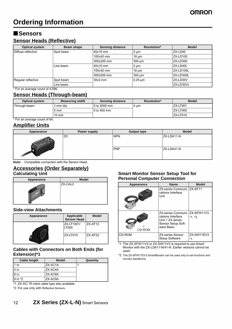
SensorsSensor Heads (Reflective)
* For an average count of 4,096.
Sensor Heads (Through-beam)
* For an average count of 64.
Amplifier Units
Note: Compatible connection with the Sensor Head.
Accessories (Order Separately)Calculating Unit
Side-view Attachments
Cables with Connectors on Both Ends (for Extension)*1
*1. ZX-XC@R robot cable type also available. *2. For use only with Reflective Sensors.
Smart Monitor Sensor Setup Tool for Personal Computer Connection
*1. The ZX-SFW11V3 or ZX-SW11V3 is required to use Smart Monitor with the ZX-LDA11-N/41-N. Earlier versions cannot be used.
*2. The ZX-SFW11EV3 SmartMonitor can be used only to set functions and monitor waveforms.
Optical system Beam shape Sensing distance Resolution* Model
Diffuse reflective Spot beam 40±10 mm 2 µm ZX-LD40
100±40 mm 16 µm ZX-LD100
300±200 mm 300 µm ZX-LD300
Line beam 40±10 mm 2 µm ZX-LD40L
100±40 mm 16 µm ZX-LD100L
300±200 mm 300 µm ZX-LD300L
Regular reflective Spot beam 30±2 mm 0.25 µm ZX-LD30V
Line beam ZX-LD30VL
Optical system Measuring width Sensing distance Resolution* Model
Through-beam 1-mm dia. 0 to 2000 mm 4 µm ZX-LT001
5 mm 0 to 500 mm ZX-LT005
10 mm ZX-LT010
Appearance Power supply Output type Model
DC NPN ZX-LDA11-N
PNP ZX-LDA41-N
Appearance Model
ZX-CAL2
Appearance Applicable Sensor Head
Model
ZX-LT1001/LT005
ZX-XF12
ZX-LT010 ZX-XF22
Cable length Model Quantity
1 m ZX-XC1A 1
4 m ZX-XC4A
8 m ZX-XC8A
9 m *2 ZX-XC9A
Appearance Name Model
ZX-series Communi-cations Interface Unit
ZX-SF11
ZX-series Communi-cations Interface Unit + ZX-series Sensor Setup Soft-ware Basic
ZX-SFW11V3*1, *2
CD-ROM ZX-series Sensor Setup Software
ZX-SW11EV3*1
+ CD-ROM

ZX Series (ZX-L-N) Smart Sensors 13
Specifications Sensor Heads (Reflective)
Note: Highly reflective objects can result in incorrect detection by causing out-of-range measurements.
Sensor Heads (Through-beam)
Item Model ZX-LD40 ZX-LD100 ZX-LD300 ZX-LD30V ZX-LD40L ZX-LD100L ZX-LD300L Z3X-LD30VL
Optical system Diffuse reflective Regular reflec-tive
Diffuse reflective Regular reflective
Light source (wave length) Visible-light semiconductor laser with a wavelength of 650 nm and an output of 1 mW max.; class 2
Measurement point 40 mm 100 mm 300 mm 30 mm 40 mm 100 mm 300 mm 30 mm
Measurement range ±10 mm ±40 mm ±200 mm ±2 mm ±10 mm ±40 mm ±200 mm ±2 mm
Beam shape Spot Line
Beam size*1
*1. Beam size: The beam size is defined by 1/e2 (13.5%) of the strength of the beam at the beam center (measured value). Incorrect detection may occur if there is light leakageoutside the defined spot and the material around the sensing object is more reflective than the sensing object.
50-µm dia. 100-µm dia. 300-µm dia. 75-µm dia. 75 µm x 2 mm 150 µm x 2 mm 450 µm x 2 mm 100 µm x 1.8 mm
Resolution*2
*2. Resolution: The resolution is the deviation (±3σ) in the linear output when connected to the ZX-LDA Amplifier Unit. (The resolution is measured with the standard reference object (white ceramic), at the measurement point with the ZX-LDA set for an average count of 4,096 per period.) The resolution is given at the repeat accuracy for a stationary workpiece, and is not an indication of the distance accuracy. The resolution may be adversely affected under strong electromagnetic fields.
2 µm 16 µm 300 µm 0.25 µm 2 µm 16 µm 300 µm 0.25 µm
Linearity*3
*3. Linearity: The linearity is given as the error in an ideal straight line displacement output when measuring the standard reference object. The linearity and measurement values vary with the object being measured.
±0.2% FS (entire range)
±0.2% FS (80 to 120 mm)
±2% FS (200 to 400 mm)
±0.2% FS (entire range)
±0.2% FS (32 to 48 mm)
±0.2% FS (80 to 120 mm)
±2% FS (200 to 400 mm)
±0.2% FS (entire range)
Temperature characteristic*4
*4. Temperature characteristic: The temperature characteristic is measured at the measurement point with the Sensor and reference object (OMRON’s standard reference object) secured with an aluminum jig.
±0.03% FS/°C (Except for ZX-LD300 and ZX-LD300L, which are ±0.1% FS/°C.)
Ambient illumination Incandescent lamp: 3,000 l× max. (on light receiving side)
Ambient temperature Operating: 0 to 50°C, Storage: −15 to 60°C (with no icing or condensation)
Ambient humidity Operating and storage: 35% to 85% (with no condensation)
Insulation resistance 20 MΩ min. at 500 VDC
Dielectric strength 1,000 VAC, 50/60 Hz for 1 min
Vibration resistance (destruction)
10 to 150 Hz, 0.7-mm double amplitude 80 min each in X, Y, and Z directions
Shock resistance (destruction)
300 m/s2 3 times each in six directions (up/down, left/right, forward/backward)
Degree of protection IEC60529, IP50 IEC60529, IP40 IEC60529, IP50 IEC60529, IP40
Connection method Connector relay (standard cable length: 500 mm)
Weight (packed state) Approx. 150 g Approx. 250 g Approx. 150 g Approx. 250 g
Materials Case: PBT (polybutylene terephthalate), Cover: Alu-minum, Lens: Glass
Case and cover: Aluminum, Lens: Glass
Case: PBT (polybutylene terephthalate), Cover: Alu-minum, Lens: Glass
Case and cover: Aluminum, Lens: Glass
Accessories Instruction sheet, Laser warning label (English)
Item Model ZX-LT001 ZX-LT005 ZX-LT010
Optical system Through-beam
Light source(wave length)
Visible-light semiconductor laser with a wavelength of 650 nm; JIS class1
Maximum output 0.2 mW max. 0.35 mW max.
Measurement width 1-mm dia. 1- to 2.5-mm dia. 5 mm 10 mm
Measurement distance
0 to 500 mm 500 to 2,000 mm 0 to 500 mm
Minimum sensing object
8-µm dia. (opaque) 8- to 50-µm dia. (opaque) 0.05-mm dia. (opaque) 0.1-mm dia. (opaque)
Resolution*1
*1. This value is obtained by converting the deviation (±3σ) in the linear output that results when the sensor head is connected to the amplifier unit, into the measurement width.
4 µm *2
*2. For an average count of 64. The value is 5 µm for an average count of 32.This is the value that results when a minimum sensing object blocks the light near the center of the 1-mm measurement width.
--- 4 µm *3
*3. For an average count of 64. The value is 5 µm for an average count of 32.
Temperature characteristic
0.2% FS/°C
Ambient illumination Incandescent lamp: 10,000 l× max. (on light-receiving side)
Ambient temperature Operating: 0 to 50°C, Storage: −25 to 70°C (with no icing or condensation)
Degree of protection IEC60529, IP40
Connection method Connector relay (standard cable length: 500 mm)
Weight (packed state) Approx. 220 g
Cable length Extendable up to 10 m with special extension cable.
Materials Case: Polyetherimide, Case cover: Polycarbonate, Unit cover: Glass
Tightening torque 0.3 N⋅m max.
Accessories Optical axis adjustment seal, sensor head-amplifier connection cable (1.5 m), instruction sheet

14 ZX Series (ZX-L-N) Smart Sensors
Amplifier Units
Calculating Unit ZX-series Communications Interface Unit
* Contact your OMRON representative for CompoWay/F communi-cations specifications.
Item Model ZX-LDA11-N ZX-LDA41-N
Measurement period 150 µs
Possible average count settings*1 1, 2, 4, 8, 16, 32, 64, 128, 256, 512, 1,024, 2,048, or 4,096
Temperature characteristic When connected to a Reflective Sensor Head: 0.01% FS/°C, When connected to a Through-beam Sensor Head: 0.1% FS/°C
Linear output*2 4 to 20 mA/FS, Max. load resistance: 300 Ω, ±4 V (± 5 V, 1 to 5 V *3), Output impedance: 100 Ω
Judgement outputs (3 outputs: HIGH/PASS/LOW)*1
NPN open-collector outputs, 30 VDC, 50 mA max.Residual voltage: 1.2 V max.
PNP open-collector outputs, 30 VDC, 50 mA max.Residual voltage: 2 V max.
Laser OFF input, zero reset input, timing input, reset input
ON: Short-circuited with 0-V terminal or 1.5 V or lessOFF: Open (leakage current: 0.1 mA max.)
ON: Supply voltage short-circuited or supply voltage within 1.5 VOFF: Open (leakage current: 0.1 mA max.)
Functions Measurement value display, set value/light level/resolution display, scaling, display reverse, display OFF mode, ECO mode, number of display digit changes, sample hold, peak hold, bottom hold, peak-to-peak hold, self-peak hold, self-bottom hold, intensity mode, zero reset, initial reset, ON-delay timer, OFF-delay timer, one-shot timer, deviation, previous value comparison, sensitivity adjustment, keep/clamp switch, direct threshold value setting, position teaching, 2-point teaching, automatic teaching, hysteresis width setting, timing inputs, reset input, monitor focus, (A-B) calculations*4, (A+B) calculations*4, mutual interference*4, laser deterioration detection, zero reset memory, key lock
Indications Operation indicators: High (orange), pass (green), low (yellow), 7-segment main display (red), 7-segment subdisplay (yellow), laser ON (green), zero reset (green), enable (green)
Power supply voltage 12 to 24 VDC ±10%, Ripple (p-p): 10% max.
Current consumption 140 mA max. with power supply voltage of 24 VDC (with Sensor connected)
Ambient temperature Operating: 0 to 50°C, Storage: −15 to 60°C (with no icing or condensation)
Ambient humidity Operating and storage: 35% to 85% (with no condensation)
Insulation resistance 20 MΩ min. at 500 VDC
Dielectric strength 1,000 VAC, 50/60 Hz for 1 min
Vibration resistance (destruction)
10 to 150 Hz, 0.7-mm double amplitude 80 min each in X, Y, and Z directions
Shock resistance (destruction)
300 m/s2 3 times each in six directions (up/down, left/right, forward/backward)
Connection method Prewired (standard cable length: 2 m)
Weight (packed state) Approx. 350 g
Materials Case: PBT (polybutylene terephthalate), Cover: Polycabonate
Accessories Instruction sheet
*1. The response speed of the linear output is calculated as the measurement period × (average count setting + 1) (with fixed sensitivity). The response speed of the judgement outputs is calculated as the measurement period × (average count setting + 1) (with fixed sensitivity).
*2. The output can be switched between a current output and voltage output using a switch on the bottom of the Amplifier Unit.*3. Setting is possible via the monitor focus function.*4. A Calculating Unit (ZX-CAL2) is required.Note: For operating details, refer to the operation manual (Cat. No. Z157).
Item ZX-CAL2
Applicable Amplifier Units
ZX-LD11-N/41-N, ZX-EDA11/41, ZX-TDA11/41
Current consumption 12 mA max. (supplied from the Smart Sensor Amplifier Unit)
Ambient temperature Operating: 0 to 50°C, Storage: −15 to 60°C (with no icing or con-densation)
Ambient humidity Operating and storage: 35% to 85% (with no condensation)
Connection method Connector
Dielectric strength 1,000 VAC, 50/60 Hz for 1 min
Insulation resistance 100 MΩ (at 500 VDC)
Vibration resistance (destructive)
10 to 150 Hz, 0.7-mm double amplitude 80 min each in X, Y, and Z directions
Shock resistance (destructive)
300 m/s2 3 times each in six directions (up/down, left/right, for-ward/backward)
Materials Display: Acrylic, Case: ABS resin
Weight (packed state) Approx. 50 g
Accessories Instruction sheet
Item ZX-SF11
Current consumption 60 mA max. (supplied by the Amplifier Unit)
Applicable Amplifier Units ZX Series
Applicable Amplifier Unit versions
ZX-LDA@1-N Ver. 1.000 or higherZX-EDA@1 Ver. 1.100 or higherZX-TDA@1 Ver. 1.000 or higher
Max. No. of Amplifier Units 5
Commu-nications functions
Communica-tions port
RS-232C port (9-pin D-Sub Connector)
Communica-tions protocol
CompoWay/F*
Baud rate 38,400 bps
Data configura-tion
Data bits: 8, Parity: none, Start bits: 1, Stop bits: 1, Flow con-trol: none
Indicators Power supply: green, Sensor communications: green, Sen-sor communications error: red, External terminal communi-cations: green, External terminal communications error: red
Protective circuits Reverse polarity protection
Ambient temperature Operating: 0 to 50°C, storage: −15 to 60°C (with no icing or condensation)
Ambient humidity Operating and storage: 35% to 85% (with no condensation)
Insulation resistance 20 MΩ min. (at 500 VDC)
Dielectric strength 1,000 VAC, 50/60 Hz for 1 min, Leakage current: 10 mA max.
Materials Case: PBT (polybutylene terephthalate), Cover: Polycarbon-ate
Accessories Instruction sheet, 2 clamps

ZX Series (ZX-L-N) Smart Sensors 15
Dimensions (Unit: mm)
Sensor Heads (Diffuse Reflective)
Sensor Heads (Regular Reflective)
33
714.8
3.4
30.05
39
A*
32
3.57
7
24.0526
46
3.5L*
17
26±0.1
32±0.1
16.612.4
5
1.8
31.1 Lens: 5 dia.
Lens: 8 dia.
Emitter axis
Receiver axis
Connector
* ZX-LD40L: L = 40 mm, A = 23°ZX-LD100L: L = 100 mm, A = 11°ZX-LD300L: L = 300 mm, A = 3.8°
Mounting Holes
Two, M3 holes
15 dia.
Range indicators
Vinyl-insulated round cable, 5.1 dia., Standard: 500 mm
Two 3.2-dia. mounting holesReference surface
Measure-ment point
ZX-LD40ZX-LD100ZX-LD300ZX-LD40LZX-LD100LZX-LD300L
47
55
Mounting Holes
Connector
Light axis
Reference plane
Lens (10 dia.)
Measurement center
Lens (16 dia.)
15 dia.
Vinyl-insulated round cable, 5.1 dia., Standard: 0.5 m
Emitter axisReceiver
axis
Two, 4.5-dia. mounting holes
46
30
32.74.754.75
45
35°
42.7
11
9.2 9.5
12.5
8.625
14
4.8
5-R2
47±0.1
Two, M4 holes
20.7
ZX-LD30VZX-LD30VL

16 ZX Series (ZX-L-N) Smart Sensors
Sensor Heads (Through-beam)
Amplifier Units
Mounting HolesMounting Holes
Emitter side Receiver side
Connector
Connector
Light axis centerLaser ON indicator
Two, 3.2 dia.
Light axis center
Two, 3.2 dia.
Vinyl-insulated round cable (black), 2.6 dia., Standard: 500 mm
9 9
5
2.819
15 15
16
9±0.1
Two, M3 holes
9±0.1
Two, M3 holes
342.8
15 15
Sensor Head-Amplifier Unit Connecting Cable (Provided)
15 dia.
Connector
Vinyl-insulated round cable (black),2.5 dia, 3-conductor
Connector2.6 dia × 2
Vinyl-insulated round cable (gray),2.5 dia, 3-conductor
46
1,500+2000
Vinyl-insulated round cable (gray), 2.6 dia., Standard: 500 mm
ZX-LT001ZX-LT005
14 20
22422.8
20
20 14
1025
20
14±0.1 14±0.1
Two, M3 holes
2.8
Two, M3 holes
Connector ConnectorLight axis centerLaser ON indicator
Two, 3.2 dia.
Light axis center
Two, 3.2 dia.
Mounting HolesMounting Holes
Emitter side Receiver side
Vinyl-insulated round cable (black), 2.6 dia., Standard: 500 mm
15 dia.
46
1,500+2000
Vinyl-insulated round cable (gray), 2.6 dia., Standard: 500 mm
Sensor Head-Amplifier Unit Connecting Cable (Provided)
Connector
Vinyl-insulated round cable (black),2.5 dia, 3-conductor
Connector2.6 dia × 2
Vinyl-insulated round cable (gray),2.5 dia, 3-conductor
ZX-LT010
364.3
15.8
13 36.8
31.5
4430
13.2
11.7
11.7
29
2.2
133
4.24.2
15.5 dia.
Voltage output
Current/voltage output selector switch (set to voltage output when shipped)
Vinyl-insulated round cable, 5.2 dia. (conductor cross-section: 0.09 mm2, 10-conductor insulator diameter: 0.7 mm), Standard: 2 m
Vinyl-insulated round cable, 5.1 dia. Standard: 100 mm
ZX-LDA11-NZX-LDA41-N

ZX Series (ZX-L-N) Smart Sensors 17
Accessories (Order Separately)ConnectorsOperation
indicators
Light axis centerTwo, 2.2 dia. Light axis centerTwo, 2.2 dia.
Seal
24.9
19.53
9.5
15
44.05
30
15.1128
2614.4
3.4 36.75
54.9
57
15
15
15
15
2.7
10.6
21
2.8
20
15.620
20
Calculating UnitZX-CAL2
Side-view AttachmentsZX-XF12 ZX-XF22
Sensor communications indicator (communications operation)
Sensor communications indicator (communications error)
Coupling connector
Power supply indicator
Connector
External terminal communications indicator (communications operation)
External terminal communicationsindicator (communications error)
Vinyl-insulated round cable, 5.23 dia. Standard: 100 mm
29
2.2
4.3
304.2
364.3 4.2
31.5
36.813
(46)(336)
15
13.2
11.7
6.5553
11.7
(33.1)
Cables with Connectors on Both Ends (for Extension)ZX-XC1A (1 m)ZX-XC4A (4 m)ZX-XC8A (8 m)ZX-XC9A (9 m)*1
46 2* 44
15 dia.
12 pins (male) 12 pins (female)
*1 For use only with the ZX-L.*2 ZX-XC1A: 1,000
ZX-XC4A: 4,000ZX-XC8A: 8,000ZX-XC9A: 9,000
15.5 dia.
Vinyl-insulated round cable, 5.2 dia., 10 conductors
ZX-series Communications Interface UnitZX-SF11

ZX
More Efficient MaintenanceComplete Compatibility betweenSensor Heads and Amplifier Units
ZX-EDA
ZX-EDA
Mutual Interference Prevented for Up to 5 Sensors
Complete Range of Useful FunctionsSimple Linearity Adjustment
Suitable for Non-ferrous Metals AlsoLinearity is worse for non-ferrous than ferrous sensing objects.A material selection function has been developed to improvelinearity with stainless steel and aluminum sensing objects.
Adjustments using the adjustment knob are no longerrequired to adjust linearity.Linearity adjustment is completed simply by teaching at0%, 50%, and 100% of the measurement distance,greatly reducing setting time.
Patent Pending
0% 50% 100%
After adjustmentSUS304AL
Measurement distance (mm)00
001.02.03.04.05.06.07.08.09.010.011.012.013.014.0
1.0 2.0 3.0 4.0 5.0 6.0 7.0
Dis
play
edva
lue
(mm
)
Multiple Sensors may be used in confined spaces for level differencemeasurements or multiple-point measurements. Mutual interferencebetween up to 5 Sensors can be prevented simply by connectingCalculating Units to eliminate the need for timing signals on the user side.
1918
Calculation Settings without Digital Panel DataThe calculation results from two Sensors can bedisplayed on the Amplifier for one Sensor simply byplacing a Calculating Unit between the Amplifier Units.The required parameters need to be input only intoone Amplifier Unit.
Sensor Head Cords Extendable to 10 m Extendable
Fixed at 2 m
Sensors with stainless steel Protective Spiral Tubes are also available.
Smallest Heads in Its Class at 3 Dia.
Wide Selection of Sensor Heads
New Flat and Heat-resistive Sensors BroadenApplication Possibilities
3 dia. 5.4 dia. 8 dia. M10 M18
Inductive Displacement Sensors for Even More Applications
Inductive Displacement Sensors
NEW NEW
Small Sensor Heads are perfect fordetecting the height of small objectsand for applications where multipleSensor Heads are used.
The temperature characteristic ranks at the top in the
industry at 0.1% FS/°C for heat-resistive sensors, and it
ranges up to 200°C for flat sensors.
The Amplifier Unit can be used as is whenreplacing damaged Sensor Heads or changingthe Sensor Head for different detection distances.
The distance between the Amplifier Units the
Sensor Heads can be extended to 3 m, 6 m,
or 10 m using a ZX-XC@A Cable (sold
separately).
Patent Pending

20 ZX Series (ZX-E) Smart Sensors (Inductive Displacement Type)
Ordering Information
SensorsSensor Heads
*1. For an average count of 4096.
*2. Models with Protective Spiral Tubes are also available. Add a suffix of “-S” to the above model numbers when ordering. (Example: ZX-ED01-S)
*3. Be sure to use ZX-EDA@ Amplifier Unit version 1,200 or later with the ZX-EV04T.
*4. Be sure to use ZX-EDA@ Amplifier Unit version 1,300 or later with the ZX-EM02HT.
Amplifier Units
Note: Compatible connection with the Sensor Head.
Accessories (Order Separately)
Amplifier Mounting Brackets
ZX-CAL2 Calculating Unit Refer to pages 12 and 14 for details.
ZX-SF11 ZX-series Communications Interface UnitRefer to pages 12 and 14 for details.
ZX-XC@A Cable with Connectors on Both Ends (for Extension)Refer to page 12 for details.
ZX-SW11V3 Smart Monitor Sensor Setup Tool for Personal Computer ConnectionRefer to page 12 for details.
Shape Dimensions Sensing distance Resolution *1 Model
Cylindrical 3 dia. x 18 mm 0.5 mm 1 µm ZX-EDR5T
5.4 dia. x 18 mm 1 mm ZX-ED01T *2
8 dia. x 22 mm 2 mm ZX-ED02T *2
Screw-shaped M10 x 22 mm ZX-EM02T *2
M18 x 46.3 mm 7 mm ZX-EM07MT *2
Flat 30 x 14 x 4.8 mm 4 mm ZX-EV04T *2 *3
Heat-resistant, cylindrical M12 x 22 mm 2 mm ZX-EM02HT *4
Appearance Power supply Output type Model
DC NPN ZX-EDA11
PNP ZX-EDA41
Appearance Model Remarks
ZX-XBE1 Attached to each Sensor Head
ZX-XBE2 For DIN track mounting

ZX Series (ZX-E) Smart Sensors (Inductive Displacement Type) 21
Specifications
Sensor Heads
*1. Resolution: The resolution is the deviation (±3 s) in the linear output when connected to the ZX-EDA Amplifier Unit. The above values indicatethe deviations observed 30 minutes after the power is turned ON.(The resolution is measured with OMRON's standard reference object at 1/2 of the measurement range with the ZX-EDA set for the maximumaverage count of 4096.) The resolution is given at the repeat accuracy for a stationary workpiece, and is not an indication of the distance accuracy. The resolution maybe adversely affected under strong electromagnetic fields.
*2. Linearity: The linearity is given as the error in an ideal straight line displacement output when measuring the standard reference object. Thelinearity and measurement values vary with the object being measured.
*3. Temperature characteristic: The temperature characteristic is measured with OMRON's standard reference object at 1/2 of the measurementrange.
*4. The ambient temperature given is only for the sensor head. It is −10 to 60°C for the preamp.
*5. The value given is for an ambient temperature of 25°C.
*6. Do not use in moist environments because the case is not waterproof.
Model ZX-EDR5T ZX-ED01T ZX-ED02T/EM02T
ZX-EM07MT ZX-EV04T ZX-EM02HT
Measurement range 0 to 0.5 mm 0 to 1 mm 0 to 2 mm 0 to 7 mm 0 to 4 mm 0 to 2 mm
Sensing object Magnetic metals (Measurement ranges and linearities are different for non-magnetic metals.)
Standard reference object 18 × 18 × 3 mm 30 × 30 × 3 mm 60 × 60 × 3 mm 45 × 45 × 3 mm
Material: ferrous (S50C)
Resolution *1 1 µm
Linearity *2 ±0.5% F.S. ±1.0% F.S. *5
Linear output range Same as measurement range.
Temperature characteristic *3 (including Amplifier Unit)
0.15% F.S./°C 0.07% F.S./°C 0.1% F.S./°C
Ambient temper-ature
Operating *4 0 to 50°C (with no icing or conden-sation)
−10 to 60°C (with no icing or condensation) −10 to 200°CStorage *4 −20 to 70°C (with no icing or condensation) −20 to 200°C
Ambient humidity Operating and storage: 35% to 85% (with no condensation)
Insulation resistance 50 MΩ min. (at 500 DC)
Dielectric strength 1,000 VAC, 50/60 Hz for 1 min between charged parts and case
Vibration resistance (destruction) 10 to 55 Hz with 1.5-mm double amplitude for 2 h each in X, Y, and Z directions
Shock resistance (destruction) 500 m/s2, 3 times each in X, Y, and Z directions
Degree of protection (Sensor Head) IEC60529, IP65 IEC60529, IP67 IEC60529, IP60 *6
Connection method Connector relay (standard cable length: 2 m)
Weight (packed state) Approx. 120 g Approx. 140 g Approx. 160 g Approx. 130 g Approx. 160 g
Materials Sensor Head
Case Brass Stainless steel Brass Zinc (nickel-plated)
Brass
Sensing surface
Heat-resistant ABS PEEK
Preamplifier PES
Accessories Amplifier Mounting Brackets (ZX-XBE1), Instruction Manual

22 ZX Series (ZX-E) Smart Sensors (Inductive Displacement Type)
Amplifier Units
*1. The response speed of the linear output is calculated as the measurement period × (average count setting + 1). The response speed of the judgement outputs is calculated as the measurement period × (average count setting + 1).
*2. The output can be switched between a current output and voltage output using a switch on the bottom of the Amplifier Unit.
*3. A Calculating Unit (ZX-CAL2) is required. Setting is possible via the monitor focus function.
*4. A Calculating Unit (ZX-CAL2) is required.
Note: For operating details, refer to the operation manual (Cat. No. Z166).
Model ZX-EDA11 ZX-EDA41
Measurement period 150 µs
Possible average count settings *1 1, 2, 4, 8, 16, 32, 64, 128, 256, 512, 1,024, 2,048, or 4,096
Linear output *2 Current output: 4 to 20 mA/F.S., Max. load resistance: 300 ΩVoltage output: ±4 V (± 5 V, 1 to 5 V *3), Output impedance: 100 Ω
Judgement outputs (3 outputs: HIGH/PASS/LOW)
NPN open-collector outputs, 30 VDC, 50 mA max.Residual voltage: 1.2 V max.
PNP open-collector outputs, 30 VDC, 50 mA max.Residual voltage: 2 V max.
Zero reset input, timing input, reset input, judgement output hold input
ON: Short-circuited with 0-V terminal or 1.5 V or less
OFF: Open (leakage current: 0.1 mA max.)
ON: Supply voltage short-circuited or supply volt-age within 1.5 V
OFF: Open (leakage current: 0.1 mA max.)
Function - Measurement value display - Present value/set value/output value/resolution display - Linearity adjustment (materials selection) - Scaling - Display reverse - Display OFF mode - ECO mode - Number of display digit changes - Sample hold - Peak hold- Bottom hold, peak-to-peak hold - Self-peak hold - Self-bottom hold - Average hold - Delay hold - Zero reset- Initial reset - Linearity initialization - ON-delay timer - OFF-delay timer - One-shot timer - Previous value comparison - Non-measurement setting - Direct threshold value setting - Position teaching - Automatic teaching - Hysteresis width setting - Timing inputs- Reset input - Judgement output hold input - Monitor focus- Linear output correction - (A-B) calculations *4 - (A+B) calculations *4 - K-(A+B) calculation *4 - Mutual interference prevention *4- Sensor disconnection detection - Zero reset memory - Zero reset indicator- Key lock
Indications Judgement indicators: High (orange), pass (green), low (yellow), 7-segment main digital display (red), 7-segment sub-digital display (yellow), power ON (green), zero reset (green), enable (green)
Voltage influence(including Sensor)
0.5% F.S. of linear output value at ±20% of power supply voltage
Power supply voltage 12 to 24 VDC ±10%, Ripple (p-p): 10% max.
Current consumption 140 mA max. with power supply voltage of 24 VDC (with Sensor connected)
Ambient temperature Operating and storage: 0 to 50°C (with no icing or condensation)
Ambient humidity Operating and storage: 35% to 85% (with no condensation)
Insulation resistance 20 MΩ min. (at 500 DC)
Dielectric strength 1,000 VAC, 50/60 Hz for 1 min
Vibration resistance (destruction) 10 to 150 Hz with 0.7-mm double amplitude for 80 min each in X, Y, and Z directions
Shock resistance (destruction) 300 m/s2, 3 times each in 6 directions (up, down, left, right, forward, backward)
Connection method Prewired (standard cable length: 2 m)
Weight (packed state) Approx. 350 g
Materials Case: PBT (polybutylene terephthalate), Cover: Polycarbonate
Accessories Instruction Manual

ZX Series (ZX-E) Smart Sensors (Inductive Displacement Type) 23
Dimensions
Sensors
Sensor Heads
27±0.1
Mounting Hole Cutout Dimensions
3 dia.(15.5)
7.8
15(22.5)
Vinyl-insulated coaxial round cable1.7 dia., 1 conductor, standard length: 2 m
7215 dia.
2715.6
58.2
Connector
(46)
(15 dia.)
15.1
Vinyl-insulated round cable5.1 dia., 9 conductors, standard length: 200 mm
18
Two, M3 holes
13
Dimensions with Mounting Bracket AttachedZX-EDR5T
5.4 dia.
18
Vinyl-insulated coaxial round cable2.5 dia., 1 conductor, standard length: 2 m 13
(15.5)
7.8
15(22.5)
7215 dia.
2715.6
58.2
Vinyl-insulated round cable5.1 dia., 9 conductors, standard length: 200 mm
Connectors
(46)
(15 dia.)
15.1
27±0.1
Mounting Hole Cutout DimensionsTwo, M3 holes
Dimensions with Mounting Bracket AttachedZX-ED01T
8 dia.(15.5)
7.8
15(22.5)
27±0.1
22
7215 dia.
2715.6
58.2
Connector
(46)
(15 dia.)
15.1
Two, M3 holes
13
Dimensions with Mounting Bracket Attached
Vinyl-insulated coaxial round cable2.5 dia., 1 conductor, standard length: 2 m
Vinyl-insulated round cable5.1 dia., 9 conductors, standard length: 200 mm
Mounting Hole Cutout Dimensions
ZX-ED02T

24 ZX Series (ZX-E) Smart Sensors (Inductive Displacement Type)
(5.4)22
8 dia.
13
(15.5)
7.8
15(22.5)
7215 dia.
2715.6
58.2
Connector
(46)
(15 dia.)
15.1
27±0.1
Two, M3 holes
2 tightening nuts
2 toothed washers
M10 × 1
18 dia.
16
Dimensions with Mounting Bracket Attached
Vinyl-insulated coaxial round cable2.5 dia., 1 conductor, standard length: 2 m
Vinyl-insulated round cable5.1 dia., 9 conductors, standard length: 200 mm
Mounting Hole Cutout Dimensions
ZX-EM02T
4
2 tightening nuts2 toothed washers
M18 × 1
15.7 dia.
(11.3)10 25
4
46.3
9.8 dia. 13
(15.5)
7.8
15(22.5)
7215 dia.
2715.6
58.2
Connector
(46)
(15 dia.)
15.1
27±0.1
Two, M3 holes
24
Dimensions with Mounting Bracket Attached
Vinyl-insulated coaxial round cable2.5 dia., 1 conductor, standard length: 2 m
Vinyl-insulated round cable5.1 dia., 9 conductors, standard length: 200 mm
Mounting Hole Cutout Dimensions
ZX-EM07MT
29 dia.
7.8
72
2715.6
58.2
15
714
4.8
1.5 15.1
7 10 10
30
13Sensing surface
(15.5)
(22.5)
15 dia.
Connector
(46)
27±0.1
Two, M3 holes
Dimensions with Mounting Bracket Attached
Vinyl-insulated coaxial round cable2.5 dia., 1 conductor, standard length: 2 m
Vinyl-insulated round cable5.1 dia., 9 conductors, standard length: 200 mm
Mounting Hole Cutout Dimensions
ZX-EV04T
Two, M3 holes
Mounting Hole Cutout Dimensions
10±0.1
(15 dia.)
Distance: 3 mm Hole size: Two, 3.3 dia.

ZX Series (ZX-E) Smart Sensors (Inductive Displacement Type) 25
Amplifier Units
72
2715.6
58.2
7.8
15(22.5)
(15.5)
13
15.1
10.5 dia.22
Fluororesin-insulated coaxial round cable2.5 dia., single conductorstandard length: 2 m
Two fastening nuts
Toothed washer(46)
M12 × 1
15 dia.
Connector
27±0.1
Two, M3 holes
Dimensions with Mounting Bracket Attached
Vinyl-insulated round cable5.1 dia., 9 conductors, standard length: 200 mm
Mounting Hole Cutout Dimensions
ZX-EM02HT
21 dia.17
4
364.3
15.8
13 36.8
31.5
44
15.5 dia.
30
13.2
11.7
11.7
292.2
133
4.24.2
Vinyl-insulated round cable5.1 dia., standard: 100 mm
Vinyl-insulated round cable5.2 dia., 10 conductors(conductor cross-section: 0.09 mm2,insulator diameter: 0.7 mm),standard length: 2 m
Current/voltage switch(Factory-set to voltage output.)
Voltage output
ZX-EDA11ZX-EDA41

26 ZX Series (ZX-E) Smart Sensors (Inductive Displacement Type)
Accessories (Sold Separately)
Preamplifier Mounting Brackets
ZX-CAL2 Calculating UnitRefer to page 17 for details.
ZX-SF11 ZX-series Communications Interface UnitRefer to page 17 for details.
ZX-XC1A (1 m), ZX-XC4A (4 m), ZX-XC8A (8 m) Cables with Connectors on Both Ends (for Extension)Refer to page 17 for details.
15.5
63.352
20
9.821.9
15.5
Material: Stainless steel (SUS304)
27±0.1 15.5
63.352
20
9.821.9
31.9
15.5
10
58
11.41.81.8
35.3
9.4
Material: Stainless steel (SUS304)
6.2 10
27±0.1
M3 × 8 pan-head screw (with M3 spring washer)
ZX-XBE1 ZX-XBE2
27±0.1
Two, M3 holes
Mounting Hole Cutout Dimensions

ZX Series (ZX-E) Smart Sensors (Inductive Displacement Type) 27
ZX
Complete Compatibility between Sensor Headsand Amplifier UnitsThe Amplifier Unit can be used as is when replacing damaged Sensor Heads or
changing the Sensor Head for a different measurement distance.
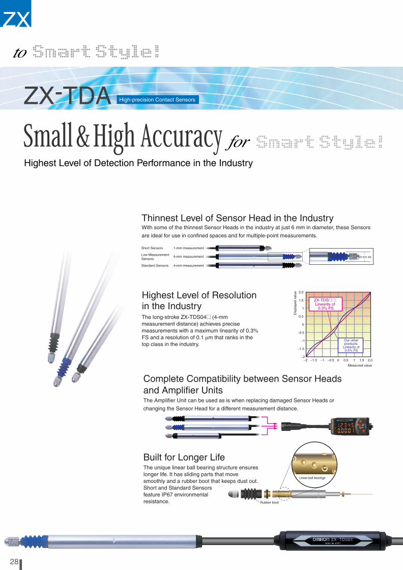
Thinnest Level of Sensor Head in the IndustryWith some of the thinnest Sensor Heads in the industry at just 6 mm in diameter, these Sensors
are ideal for use in confined spaces and for multiple-point measurements.
6-mm dia.
Highest Level of Resolutionin the Industry
−2−2
−1.5
−1.5
−1
−1
−0.5
−0.5
0.5
0.5
1
1
1.5
1.5
2.0
Measured value
2.0
0
0
ZX-TDS@@:Linearity of
0.3% FS
Dis
play
edva
lue
1ch1ch2ch
2ch -1ch
3ch
3ch -1ch
4ch
4ch -1ch
Warm-up Display
Connect up to 8 Sensor Heads.
Multiple-pointComputing Function
Early Warning Detection Function
×101%
SimultaneousH and L output
Ana
log
char
acte
ristic
s
Origin Alignment No Longer Required
Auto-scaling Function
Fixed at 2 m
Extendable
Built for Longer Life
Linear ball bearings
Rubber boot
ZX-TDA
ZX-TDA
2928
Standard Sensors 4-mm measurement
Low MeasurementSensors
Short Sensors 1-mm measurement
High-precision Contact Sensors
Highest Level of Detection Performance in the Industry
4-mm measurement
The long-stroke ZX-TDS04@ (4-mmmeasurement distance) achieves precisemeasurements with a maximum linearity of 0.3%FS and a resolution of 0.1 µm that ranks in thetop class in the industry.
Our otherproducts:
Linearity of0.5% FS
The unique linear ball bearing structure ensureslonger life. It has sliding parts that movesmoothly and a rubber boot that keeps dust out.Short and Standard Sensorsfeature IP67 environmentalresistance.
Data obtained from one Sensorcan be added and subtracted fromthe data for up to 7 other Sensors.
In non-measurement situations, this function detectswhether the Sensor is in danger of being damaged byoverpressing and outputs an alarm signal. A sequencecan be added with devices such as PLCs to providemeasures to avoid damage, such as stoppingmeasurements when this occurs.
Measurementdistance
After the power is turned ON, the warm-up display indicateswhen the Sensor is ready to start measuring at optimumconditions (i.e. at the specified resolution).
The measurement distance can bedisplayed on the Amplifier simply byconnecting the Sensor Head. Thedistance between the Amplifier Units andSensor Heads can be extended to 3 m, 6m, or 10 m using a ZX-XC@A Cable(sold separately).
The differential transformer system eliminates theneed for master adjustment and origin alignmentevery time the system is started. It also eliminatesthe time-consuming step of returning to the originwhen power is interrupted.

ZX
Complete Compatibility between Sensor Headsand Amplifier UnitsThe Amplifier Unit can be used as is when replacing damaged Sensor Heads or
changing the Sensor Head for a different measurement distance.
Thinnest Level of Sensor Head in the IndustryWith some of the thinnest Sensor Heads in the industry at just 6 mm in diameter, these Sensors
are ideal for use in confined spaces and for multiple-point measurements.
6-mm dia.
Highest Level of Resolutionin the Industry
−2−2
−1.5
−1.5
−1
−1
−0.5
−0.5
0.5
0.5
1
1
1.5
1.5
2.0
Measured value
2.0
0
0
ZX-TDS@@:Linearity of
0.3% FS
Dis
play
edva
lue
1ch1ch2ch
2ch -1ch
3ch
3ch -1ch
4ch
4ch -1ch
Warm-up Display
Connect up to 8 Sensor Heads.
Multiple-pointComputing Function
Early Warning Detection Function
×101%
SimultaneousH and L output
Ana
log
char
acte
ristic
s
Origin Alignment No Longer Required
Auto-scaling Function
Fixed at 2 m
Extendable
Built for Longer Life
Linear ball bearings
Rubber boot
ZX-TDA
ZX-TDA
2928
Standard Sensors 4-mm measurement
Low MeasurementSensors
Short Sensors 1-mm measurement
High-precision Contact Sensors
Highest Level of Detection Performance in the Industry
4-mm measurement
The long-stroke ZX-TDS04@ (4-mmmeasurement distance) achieves precisemeasurements with a maximum linearity of 0.3%FS and a resolution of 0.1 µm that ranks in thetop class in the industry.
Our otherproducts:
Linearity of0.5% FS
The unique linear ball bearing structure ensureslonger life. It has sliding parts that movesmoothly and a rubber boot that keeps dust out.Short and Standard Sensorsfeature IP67 environmentalresistance.
Data obtained from one Sensorcan be added and subtracted fromthe data for up to 7 other Sensors.
In non-measurement situations, this function detectswhether the Sensor is in danger of being damaged byoverpressing and outputs an alarm signal. A sequencecan be added with devices such as PLCs to providemeasures to avoid damage, such as stoppingmeasurements when this occurs.
Measurementdistance
After the power is turned ON, the warm-up display indicateswhen the Sensor is ready to start measuring at optimumconditions (i.e. at the specified resolution).
The measurement distance can bedisplayed on the Amplifier simply byconnecting the Sensor Head. Thedistance between the Amplifier Units andSensor Heads can be extended to 3 m, 6m, or 10 m using a ZX-XC@A Cable(sold separately).
The differential transformer system eliminates theneed for master adjustment and origin alignmentevery time the system is started. It also eliminatesthe time-consuming step of returning to the originwhen power is interrupted.

30 ZX Series (ZX-T) Smart Sensors (High-precision Contact Type)
Ordering Information
Sensors
Sensor Heads
Note:The resolution refers to the minimum value that can be read when a ZX-TDA@1 Amplifier Unit is connected.
Amplifier Units
Accessories (Order Separately)
Preamplifier Mounting Brackets
ZX-CAL2 Calculating UnitRefer to pages 12 and 14 for details.
ZX-SF11 ZX-series Communications Interface UnitRefer to pages 12 and 14 for details.
ZX-XC@A Cable with Connectors on Both Ends (for Extension)Refer to page 12 for details.
ZX-SW11V3 Smart Monitor Sensor Setup Tool for Personal Computer ConnectionRefer to page 12 for details.
Size Type Sensing distance Resolution (See note.) Model
6 dia. Short type 1 mm 0.1 µm ZX-TDS01T
6 dia. Standard type 4 mm 0.1 µm ZX-TDS04T
6 dia. Low measurement type 4 mm 0.1 µm ZX-TDS04T-L
Appearance Power supply Output type Model
DC NPN ZX-TDA11
PNP ZX-TDA41
Appearance Model Remarks
ZX-XBT1 Attached to each Sensor Head
ZX-XBT2 For DIN track mount-ing

ZX Series (ZX-T) Smart Sensors (High-precision Contact Type) 31
Specifications
Sensor Heads
*1. The resolution is given as the minimum value that can be read when a ZX-TDA@1 Amplifier Unit is connected. This value is taken 15 minutes after turning ON the power with the average number of operations set to 256.
*2. The linearity is given as the error in an ideal straight line displacement output.
*3. These figures are representative values that apply for the measurement mid-point, and are for when the provided actuator is used, with the actuator moving downwards. If the actuator moves horizontally or upwards, the operating force will be reduced. Also, if an actuator other than the standard one is used, the operating force will vary with the weight of the actuator itself.
*4. These figures are representative values that apply for the mid-point of the measurement range.
Item ZX-TDS01T ZX-TDS04T ZX-TDS04T-L
Measurement range 1 mm 4 mm
Maximum actuator travel distance Approx. 1.5 mm Approx. 5 mm
Resolution *1 0.1 µm
Linearity *2 0.3% F.S.
Operating force *3 Approx. 0.7 N Approx. 0.25 N
Degree of protection (Sensor Head) IEC60529, IP67 IEC60529, IP54
Mechanical durability 10,000,000 operations min.
Ambient temperature Operating: 0°C to 50°C (with no icing or condensation)Storage: −15°C to 60°C (with no icing or condensation)
Ambient humidity Operating and storage: 35% to 85% (with no icing or condensation)
Temperature characteristic *4
Sensor Head 0.03% F.S./°C 0.01% F.S./°CPreamplifier 0.01% F.S./°C
Vibration resistance (destruction)
10 to 55 Hz with 0.35-mm single amplitude in the X, Y, and Z directions
Shock resistance (destruction)
150 m/s2, 3 times each in the X, Y, and Z directions
Connection method Connector relay (standard cable length: 2 m)
Isolation Isolated (Sensor Head enclosure and I/O lines)
Weight (packed state) Approx. 100 g
Materials Sensor Head Stainless steel
Rubber boot Fluorocarbon rubber Silicon rubber
Preamplifier Polycarbonate
Accessories Instruction manual, Preamplifier Mounting Brackets (ZX-XBT1)

32 ZX Series (ZX-T) Smart Sensors (High-precision Contact Type)
Amplifier Units
*1. The response speed of the linear output is calculated as the measurement period × (average count setting + 1). The response speed of the judgement outputs is calculated as the measurement period × (average count setting + 1).
*2. The output can be switched between a current output and voltage output using a switch on the bottom of the Amplifier Unit.
*3. Setting is possible via the monitor focus function.
*4. A Calculating Unit (ZX-CAL2) is required.
Note: For operating details, refer to the operation manual (Cat. No. E346) provided by OMRON.
Options (Actuators)
Note: For optional Actuator combinations, the circle means the Actuator is replaceable and the triangle means that a Conversion Adapter is required.
Dimensions
Item ZX-TDA11 ZX-TDA41
Measurement period 1 ms
Possible average count settings *1 1, 2, 4, 8, 16, 32, 64, 128, 256, 512, or 1,024
Linear output *2 Current output: 4 to 20 mA/F.S., Max. load resistance: 300 ΩVoltage output: ±4 V (±5 V, 1 to 5 V), Output impedance: 100 Ω
Judgement outputs (3 outputs: HIGH/PASS/LOW)
NPN open-collector outputs, 30 VDC, 30 mA max.Residual voltage: 1.2 V max.
PNP open-collector outputs, 30 VDC, 30 mA max.Residual voltage: 2 V max.
Zero reset input, timing input, reset in-put, judgement output hold input
ON: Short-circuited with 0-V terminal or 1.5 V or less
OFF: Open (leakage current: 0.1 mA max.)
ON: Supply voltage short-circuited or supply voltage of 1.5 V or less
OFF: Open (leakage current: 0.1 mA max.)
Function - Measurement value display - Present value/set value/output value display - Display reverse - ECO mode - Number of display digit changes- Sample hold - Peak hold - Bottom hold, peak-to-peak hold- Self-peak hold - Self-bottom hold - Zero reset- Initial reset - Direct threshold value setting - Position teaching - Hysteresis width setting - Timing inputs - Reset input- Judgement output hold input - Monitor focus - (A-B) calculations *4- (A+B) calculations *4 - Sensor disconnection detection- Zero reset memory - Function lock - Non-measurement setting- Clamp value setting - Scale inversion - Zero reset indicator- Span adjustment - Warming-up display - Pressing force alarm
Indicators Judgement indicators: High (orange), pass (green), low (yellow), 7-segment main digital display (red), 7-segment sub-digital display (yellow), power ON (green), zero reset (green), enable (green)
Power supply voltage 12 to 24 VDC ±10%, Ripple (p-p): 10% max.
Current consumption 140 mA max. (with Sensor connected), For 24-VDC power supply: 140 mA max. (with Sensor connected)
Ambient temperature Operating and storage: 0 to 50°C (with no icing or condensation)
Ambient humidity Operating and storage: 35% to 85% (with no icing or condensation)
Temperature characteristic 0.03% F.S./°C
Insulation resistance 20 MΩ min. at 500 VDC
Dielectric strength 1,000 VAC, 50/60 Hz for 1 min
Vibration resistance (destruction) 10 to 150 Hz with 0.7-mm double amplitude for 80 min each in X, Y, and Z directions
Shock resistance (destruction) 300 m/s2, 3 times each in six directions (up, down, left, right, forward, backward)
Connection method Prewired (standard cable length: 2 m)
Weight (packed state) Approx. 350 g
Materials Case: PBT (polybutylene terephthalate), Cover: Polycarbonate
Accessories Instruction sheet
Model Type (material) Screw section Appearance Application Applicable Sensor *
ZX-TDS@T
D5SN- TB1 Ball type (steel) Female screwM2.5 x 0.45
Measuring ordinary flat surfaces (standard actuator supplied with the ZX-TDS Series)
TB2 Ball type (carbide steel) Female screwM2.5 x 0.45
Measurements where abrasion resistance is criticalMeasured objects: Carbide (HR90) or lower.
TB3 Ball type (ruby) Female screwM2.5 x 0.45
Measurements where abrasion resistance is criticalMeasured objects: Carbide (HR90) or higher.
TN1 Needle type (carbide steel) Male screwM2.5 x 0.45
Measuring the bottom of grooves and holes
TF1 Flat (carbide steel) Male screwM2.5 x 0.45
Measuring spherical objects
TA Conversion Adapter (stainless steel)
Through-hole fe-male screwM2.5 x 0.45
Mounting D5SN-TN1/-TF1 or commercially available actuators on ZX-TDS-series Sensors
D5SN-TB1/TB2/TB3 D5SN-TN1 D5SN-TF1 D5SN-TA
3.5
4.5 dia.
M2.5
5.5
SR1.5
6.5±0.2
C0.3
Crisscross pattern m0.2
3.5 dia.
3 7
10
(15)
5
1 dia. 5 dia.
Carbide steelM2.5±0.45
4.3 dia.5.2 dia.
M2.5 × 0.45
55
3.3
(10) Grooves m0.22-C0.2
12
5 dia.
Carbide steel
M2.55 (Through hole)

ZX Series (ZX-T) Smart Sensors (High-precision Contact Type) 33
Dimensions
SensorsZX-TDS01T
ZX-TDS04TZX-TDS04T-L
Amplifier UnitsZX-TDA11ZX-TDA41
41.644.6
57.1±1
5.95
16
46
4.5 dia. 15 dia.
SR1.5
Vinyl-insulated round cable3.7 dia., standard length: 2 m
Measurement range*
Vinyl-insulated round cable5.2 dia., standard length: 200 mm
Connector
* Measurement range: 11.2 to 12.2 (TYP)
27
2020
27±0.1
Mounting Hole Cutout Dimensions
Two, M3
84.8
6 dia.00.1
9797±±11
97±1
88
63.466.4
86 ±1.5
13.1
16
46
4.5 dia.
15 dia.
SR1.5
Vinyl-insulated round cable3.7 dia., standard length: 2 m
Measurement range*
Connector
Vinyl-insulated round cable5.2 dia., standard length: 200 mm
* Measurement range: 14.9 to 18.9 (TYP)
2784.8
27±0.1
Mounting Hole Cutout Dimensions
Two, M3
6 dia.0
−0.1
8897±1
97±1
2784.8
20
15 dia.
15.8
31.5
11.7
364.3
13 36.8
44
15.5 dia.
30
13.2
11.7
29
2.2
133
4.24.2
Vinyl-insulated round cable 5.1 dia., standard length: 100 mm
Vinyl-insulated round cable 5.2 dia., 10 conductors, (conductor cross-section: 0.09 mm2, insulator diameter: 0.7-mm dia.), standardlength: 2 m
Current/voltage switch (Factory-set to voltage output)
Voltage output

34 ZX Series (ZX-T) Smart Sensors (High-precision Contact Type)
Accessories (Order Separately)
Preamplifier Mounting Bracket (Supplied with Each Sensor)ZX-XBT1 ZX-XBT2 (For DIN Track Mounting)
ZXCAL2 Calculating UnitRefer to page 17 for details.
ZX-SF11 ZX-series Communications Interface UnitRefer to page 17 for details.
ZX-XC1A (1 m), ZX-XC4A (4 m), ZX-XC8A (8 m) Cables with Connectors on Both Ends (for Extension)Refer to page 17 for details.
27
3.2
Four, 1.6R4.8
(91.1)
(28.1)
(16.4)
Material: Stainless steel
27±0.1
Mounting Hole Cutout Dimensions
Two, M3
M3 x 8 pan-head screw (with M3 spring washer)
29
75
(91.1)
6.210(38)
1.81.8
9.411.435.3
58
84.8
11.8(28.1)
(16.4)
10
Material: Stainless steel

ZX Series Smart Sensors 35
Precautions
Design PrecautionsConform to the specified ratings and performance. Refer to the Spec-ifications for each product on the following pages.
ZX-L: Pages 13 and 14
ZX-E: Pages 21 and 22
ZX-T: Pages 31 and 32
EnvironmentDo not operate the product in locations subject to flammable or explo-sive gases.
In order to ensure safe operation and maintenance, do not install the product in the vicinity of high-voltage devices or power equipment.
WiringDo not use the product at voltages exceeding the rated values. Doing so may result in damage.
Do not connect the product to an AC power supply or connect the power supply in reverse.
Do not short loads connected to open-collector outputs.
Do not lay the cable for the product together with or in the same duet as high-voltage lines or power lines. Doing so may result in incorrect operation or damage due to induction.
Other PrecautionsDo not attempt to disassemble, repair, or modify the product.
Dispose of the product using standard procedures for industrial waste.
Do not connect combinations of ZX-L@@-, ZX-E@@-, and ZX-T@@-series Smart Sensors.
Correct UseThis product consists of precision parts that may fail if it is dropped.
Design PrecautionsCompatibilitySensors and Amplifier Units are mutually compatible. Sensors can be added or replaced individually.
Influence of High-frequency Electromagnetic FieldsUsing the product in the vicinity of devices that generate high-fre-quency electromagnetic fields, such as ultrasonic cleaning equip-ment, high-frequency generators, transceivers, mobile phones, and inverters, may result in malfunction.
Wiring
Wiring CheckAfter wiring is completed, before turning ON the power, confirm that the power supply is connected correctly, that there are no faulty con-nections, such as load short-circuits, and that the load current is cor-rect. Incorrect wiring may result in failure.
Cable ExtensionDo not extend the cable for the Sensor and the Amplifier Unit to a length exceeding 10 m. Use a ZX-XC@A Extension Cable (sold sep-arately) to extend the Sensor’s cable. Extend the Amplifier Unit’s ca-ble using a shielded cable of the same type.
Power SupplyWhen using a commercially available switching regulator, ground the FG (frame ground) terminal.
If the power supply line is subject to surges, connect a surge absorber that meets the conditions of the operating environment.
Calculating UnitWhen using a Calculating Unit, connect the linear output ground of the corresponding Amplifier Unit.
ConnectorsDo not connect or disconnect connectors while the power is ON.
Be sure hold to connectors by the cover when connecting or discon-necting.
Installation LocationDo not install the product in the following locations.
• Locations subject to temperatures outside the specified range• Locations subject to condensation due to sudden temperature
changes• Locations subject to humidity levels outside range 35% to 85%• Locations subject to corrosive or flammable gases• Locations subject to dust, salts, or metallic powder.• Locations directly subject to vibrations and shocks• Locations subject to splashes of water, oil, or chemicals• Locations subject to strong electromagnetic or electrical fields
Maintenance and Inspection• Be sure to turn OFF the power supply before adjusting or removing
the Sensor Head.• Cleaning:
Do not use thinners, benzine, acetone, or kerosene for cleaning.

Terms and Conditions of Sale1. Offer; Acceptance. These terms and conditions (these "Terms") are deemed
part of all quotes, agreements, purchase orders, acknowledgments, price lists,catalogs, manuals, brochures and other documents, whether electronic or inwriting, relating to the sale of products or services (collectively, the "Products")by Omron Electronics LLC and its subsidiary companies (“Omron”). Omronobjects to any terms or conditions proposed in Buyer’s purchase order or otherdocuments which are inconsistent with, or in addition to, these Terms.
2. Prices; Payment Terms. All prices stated are current, subject to change with-out notice by Omron. Omron reserves the right to increase or decrease priceson any unshipped portions of outstanding orders. Payments for Products aredue net 30 days unless otherwise stated in the invoice.
3. Discounts. Cash discounts, if any, will apply only on the net amount of invoicessent to Buyer after deducting transportation charges, taxes and duties, and willbe allowed only if (i) the invoice is paid according to Omron’s payment termsand (ii) Buyer has no past due amounts.
4. Interest. Omron, at its option, may charge Buyer 1-1/2% interest per month orthe maximum legal rate, whichever is less, on any balance not paid within thestated terms.
5. Orders. Omron will accept no order less than $200 net billing. 6. Governmental Approvals. Buyer shall be responsible for, and shall bear all
costs involved in, obtaining any government approvals required for the impor-tation or sale of the Products.
7. Taxes. All taxes, duties and other governmental charges (other than generalreal property and income taxes), including any interest or penalties thereon,imposed directly or indirectly on Omron or required to be collected directly orindirectly by Omron for the manufacture, production, sale, delivery, importa-tion, consumption or use of the Products sold hereunder (including customsduties and sales, excise, use, turnover and license taxes) shall be charged toand remitted by Buyer to Omron.
8. Financial. If the financial position of Buyer at any time becomes unsatisfactoryto Omron, Omron reserves the right to stop shipments or require satisfactorysecurity or payment in advance. If Buyer fails to make payment or otherwisecomply with these Terms or any related agreement, Omron may (without liabil-ity and in addition to other remedies) cancel any unshipped portion of Prod-ucts sold hereunder and stop any Products in transit until Buyer pays allamounts, including amounts payable hereunder, whether or not then due,which are owing to it by Buyer. Buyer shall in any event remain liable for allunpaid accounts.
9. Cancellation; Etc. Orders are not subject to rescheduling or cancellationunless Buyer indemnifies Omron against all related costs or expenses.
10. Force Majeure. Omron shall not be liable for any delay or failure in deliveryresulting from causes beyond its control, including earthquakes, fires, floods,strikes or other labor disputes, shortage of labor or materials, accidents tomachinery, acts of sabotage, riots, delay in or lack of transportation or therequirements of any government authority.
11. Shipping; Delivery. Unless otherwise expressly agreed in writing by Omron:a. Shipments shall be by a carrier selected by Omron; Omron will not drop ship
except in “break down” situations.b. Such carrier shall act as the agent of Buyer and delivery to such carrier shall
constitute delivery to Buyer;c. All sales and shipments of Products shall be FOB shipping point (unless oth-
erwise stated in writing by Omron), at which point title and risk of loss shallpass from Omron to Buyer; provided that Omron shall retain a security inter-est in the Products until the full purchase price is paid;
d. Delivery and shipping dates are estimates only; ande. Omron will package Products as it deems proper for protection against nor-
mal handling and extra charges apply to special conditions.12. Claims. Any claim by Buyer against Omron for shortage or damage to the
Products occurring before delivery to the carrier must be presented in writingto Omron within 30 days of receipt of shipment and include the original trans-portation bill signed by the carrier noting that the carrier received the Productsfrom Omron in the condition claimed.
13. Warranties. (a) Exclusive Warranty. Omron’s exclusive warranty is that theProducts will be free from defects in materials and workmanship for a period oftwelve months from the date of sale by Omron (or such other period expressedin writing by Omron). Omron disclaims all other warranties, express or implied.(b) Limitations. OMRON MAKES NO WARRANTY OR REPRESENTATION,EXPRESS OR IMPLIED, ABOUT NON-INFRINGEMENT, MERCHANTABIL-
ITY OR FITNESS FOR A PARTICULAR PURPOSE OF THE PRODUCTS.BUYER ACKNOWLEDGES THAT IT ALONE HAS DETERMINED THAT THEPRODUCTS WILL SUITABLY MEET THE REQUIREMENTS OF THEIRINTENDED USE. Omron further disclaims all warranties and responsibility ofany type for claims or expenses based on infringement by the Products or oth-erwise of any intellectual property right. (c) Buyer Remedy. Omron’s sole obli-gation hereunder shall be, at Omron’s election, to (i) replace (in the formoriginally shipped with Buyer responsible for labor charges for removal orreplacement thereof) the non-complying Product, (ii) repair the non-complyingProduct, or (iii) repay or credit Buyer an amount equal to the purchase price ofthe non-complying Product; provided that in no event shall Omron be responsi-ble for warranty, repair, indemnity or any other claims or expenses regardingthe Products unless Omron’s analysis confirms that the Products were prop-erly handled, stored, installed and maintained and not subject to contamina-tion, abuse, misuse or inappropriate modification. Return of any Products byBuyer must be approved in writing by Omron before shipment. Omron Compa-nies shall not be liable for the suitability or unsuitability or the results from theuse of Products in combination with any electrical or electronic components,circuits, system assemblies or any other materials or substances or environ-ments. Any advice, recommendations or information given orally or in writing,are not to be construed as an amendment or addition to the above warranty.See http://oeweb.omron.com or contact your Omron representative for pub-lished information.
14. Limitation on Liability; Etc. OMRON COMPANIES SHALL NOT BE LIABLEFOR SPECIAL, INDIRECT, INCIDENTAL, OR CONSEQUENTIAL DAMAGES,LOSS OF PROFITS OR PRODUCTION OR COMMERCIAL LOSS IN ANYWAY CONNECTED WITH THE PRODUCTS, WHETHER SUCH CLAIM ISBASED IN CONTRACT, WARRANTY, NEGLIGENCE OR STRICT LIABILITY.Further, in no event shall liability of Omron Companies exceed the individualprice of the Product on which liability is asserted.
15. Indemnities. Buyer shall indemnify and hold harmless Omron Companies andtheir employees from and against all liabilities, losses, claims, costs andexpenses (including attorney's fees and expenses) related to any claim, inves-tigation, litigation or proceeding (whether or not Omron is a party) which arisesor is alleged to arise from Buyer's acts or omissions under these Terms or inany way with respect to the Products. Without limiting the foregoing, Buyer (atits own expense) shall indemnify and hold harmless Omron and defend or set-tle any action brought against such Companies to the extent based on a claimthat any Product made to Buyer specifications infringed intellectual propertyrights of another party.
16. Property; Confidentiality. Any intellectual property in the Products is the exclu-sive property of Omron Companies and Buyer shall not attempt to duplicate itin any way without the written permission of Omron. Notwithstanding anycharges to Buyer for engineering or tooling, all engineering and tooling shallremain the exclusive property of Omron. All information and materials suppliedby Omron to Buyer relating to the Products are confidential and proprietary,and Buyer shall limit distribution thereof to its trusted employees and strictlyprevent disclosure to any third party.
17. Export Controls. Buyer shall comply with all applicable laws, regulations andlicenses regarding (i) export of products or information; (iii) sale of products to“forbidden” or other proscribed persons; and (ii) disclosure to non-citizens ofregulated technology or information.
18. Miscellaneous. (a) Waiver. No failure or delay by Omron in exercising any rightand no course of dealing between Buyer and Omron shall operate as a waiverof rights by Omron. (b) Assignment. Buyer may not assign its rights hereunderwithout Omron's written consent. (c) Law. These Terms are governed by thelaw of the jurisdiction of the home office of the Omron company from whichBuyer is purchasing the Products (without regard to conflict of law princi-ples). (d) Amendment. These Terms constitute the entire agreement betweenBuyer and Omron relating to the Products, and no provision may be changedor waived unless in writing signed by the parties. (e) Severability. If any provi-sion hereof is rendered ineffective or invalid, such provision shall not invalidateany other provision. (f) Setoff. Buyer shall have no right to set off any amountsagainst the amount owing in respect of this invoice. (g) Definitions. As usedherein, “including” means “including without limitation”; and “Omron Compa-nies” (or similar words) mean Omron Corporation and any direct or indirectsubsidiary or affiliate thereof.
Certain Precautions on Specifications and Use1. Suitability of Use. Omron Companies shall not be responsible for conformity
with any standards, codes or regulations which apply to the combination of theProduct in the Buyer’s application or use of the Product. At Buyer’s request,Omron will provide applicable third party certification documents identifyingratings and limitations of use which apply to the Product. This information byitself is not sufficient for a complete determination of the suitability of the Prod-uct in combination with the end product, machine, system, or other applicationor use. Buyer shall be solely responsible for determining appropriateness ofthe particular Product with respect to Buyer’s application, product or system.Buyer shall take application responsibility in all cases but the following is anon-exhaustive list of applications for which particular attention must be given:(i) Outdoor use, uses involving potential chemical contamination or electricalinterference, or conditions or uses not described in this document.(ii) Use in consumer products or any use in significant quantities. (iii) Energy control systems, combustion systems, railroad systems, aviationsystems, medical equipment, amusement machines, vehicles, safety equip-ment, and installations subject to separate industry or government regulations. (iv) Systems, machines and equipment that could present a risk to life or prop-erty. Please know and observe all prohibitions of use applicable to this Prod-uct. NEVER USE THE PRODUCT FOR AN APPLICATION INVOLVING SERIOUSRISK TO LIFE OR PROPERTY OR IN LARGE QUANTITIES WITHOUTENSURING THAT THE SYSTEM AS A WHOLE HAS BEEN DESIGNED TO
ADDRESS THE RISKS, AND THAT THE OMRON’S PRODUCT IS PROP-ERLY RATED AND INSTALLED FOR THE INTENDED USE WITHIN THEOVERALL EQUIPMENT OR SYSTEM.
2. Programmable Products. Omron Companies shall not be responsible for theuser’s programming of a programmable Product, or any consequence thereof.
3. Performance Data. Data presented in Omron Company websites, catalogsand other materials is provided as a guide for the user in determining suitabil-ity and does not constitute a warranty. It may represent the result of Omron’stest conditions, and the user must correlate it to actual application require-ments. Actual performance is subject to the Omron’s Warranty and Limitationsof Liability.
4. Change in Specifications. Product specifications and accessories may bechanged at any time based on improvements and other reasons. It is our prac-tice to change part numbers when published ratings or features are changed,or when significant construction changes are made. However, some specifica-tions of the Product may be changed without any notice. When in doubt, spe-cial part numbers may be assigned to fix or establish key specifications foryour application. Please consult with your Omron’s representative at any timeto confirm actual specifications of purchased Product.
5. Errors and Omissions. Information presented by Omron Companies has beenchecked and is believed to be accurate; however, no responsibility is assumedfor clerical, typographical or proofreading errors or omissions.

$%"=GG<"=GGG ("=GG
Cat. No. E351-E1-02 8/06 Specifications subject to change without notice Printed in USA
! "#992; # !;*2F9
$%&'&&$&(
( -# %!7'415,
$)$*)+,,6< 3 =
,,((&&)&&
- ./ 012
111# # 3H/- 2.2"/4#
!56 ## !%11,:,5# !%11,25
Related Documents


